RSA-PE-20 - Universidad Autónoma...
34
AQ-00073-000, Rev. 7 RSA-PE-20 Introduction .................................................................................. 1 Unpacking and Inspection ........................................................... 2 Installation and Assembly ........................................................... 3 Installing the Accessory PC Board Kit ................................ 3 Installing the Accessory in Your Sample Compartment ...... 6 Accessory Alignment ........................................................... 6 Diagnostic Scans .................................................................. 8 System Description and Operation ........................................... 11 Integrating Sphere .............................................................. 11 Transfer Optics .................................................................. 12 Loading the Sample Holders ............................................. 12 Theory of Operation .......................................................... 13 Operating Procedures for the RSA-PE-20 Accessory ....... 21 Maintenance ............................................................................... 26 General Information ........................................................... 26 Mirror Cleaning Procedure ................................................ 26 Spectralon Cleaning Instructions ....................................... 26 Appendix A Specifications ........................................................ 27 Appendix B Typical Spectralon Reflectance Values ............... 28 Appendix C Substitution Error Sample Scans ....................... 29 Appendix D Reflectance Glossary ............................................ 31 Appendix E Recommended Reading ....................................... 33
-
Upload
nguyenxuyen -
Category
Documents
-
view
215 -
download
0
Transcript of RSA-PE-20 - Universidad Autónoma...

AQ-00073-000, Rev. 7
RSA-PE-20
Introduction .................................................................................. 1
Unpacking and Inspection ........................................................... 2
Installation and Assembly ........................................................... 3Installing the Accessory PC Board Kit ................................ 3Installing the Accessory in Your Sample Compartment ...... 6Accessory Alignment ........................................................... 6Diagnostic Scans .................................................................. 8
System Description and Operation ........................................... 11Integrating Sphere .............................................................. 11Transfer Optics .................................................................. 12Loading the Sample Holders ............................................. 12Theory of Operation .......................................................... 13Operating Procedures for the RSA-PE-20 Accessory ....... 21
Maintenance ............................................................................... 26General Information ........................................................... 26Mirror Cleaning Procedure ................................................ 26Spectralon Cleaning Instructions ....................................... 26
Appendix A Specifications ........................................................ 27
Appendix B Typical Spectralon Reflectance Values ............... 28
Appendix C Substitution Error Sample Scans ....................... 29
Appendix D Reflectance Glossary ............................................ 31
Appendix E Recommended Reading ....................................... 33

Introduction
The Labsphere RSA-PE-20 is a diffuse reflectance and transmittance accessory designed for a number of PerkinElmer UV-VIS spectrometers. The list of compatible spectrometers includes the Lambda 25/35/45 series as well as the older models Lambda 2/12/14/20/40.
The RSA-PE-20 accessory essentially is an optical bench, including transfer optics and an inte-grating sphere, that fits neatly into the sample compartment of the spectrometer instrument. An illustration of the accessory is provided in Figure 1. Since the reference beam passes through the accessory unimpeded, the RSA-PE-20 accommodates either single or double beam configura-tion spectrometer. The accessory, however, is a single beam device. The accessory is ideal for measuring diffuse reflectance or transmittance for scientific and industrial applications including color, thermochromism, composition of opaque materials such as biological or geological speci-mens. The geometric measurement capabilities of the accessory include 8° /hemispherical reflectance, 0° /diffuse reflectance, 0° /hemispherical transmittance and 0°/diffuse transmittance. Sample holders for the test and reference samples are supplied with the accessory.
This manual provides the installation and operating procedures for the RSA-PE-20. The opera-tion of your spectrometer system with the integrating sphere accessory installed, however, essen-tially is unchanged. Since the procedures may vary from one spectrometer to the next, you should consult your PerkinElmer instruction manual when taking reflectance and transmittance measurements.
Figure 1. The RSA-PE-20 fits into the sample compartment of your PerkinElmer spectrometer.
AQ-00073-000, Rev. 7 1

Unpacking and Inspection
The RSA-PE-20 was thoroughly inspected and calibrated before shipping and should be ready to operate after completing the set-up instructions. All Labsphere instrumentation is packaged and shipped in reinforced shipping containers. The RSA-PE-20 is sold in two different configura-tions, depending on the source of your order and the model number of your PerkinElmer UV/VIS spectrometer. Carefully check the components after unpacking for any damage that may have occurred during shipping. If there is any such damage, file a claim immediately with the freight carrier and contact the Labsphere Customer Service Department at
!(603) 927-4266.
Standard components accompanying all orders:
• RSA-PE-20 Accessory • One 8° and two 0° sample holders • Accessory cable assembly • Cuvette Holder • Tool Kit • USRS-99-010 Uncalibrated Spectralon Reflectance Standard • Instruction Manual
If your system was ordered directly from Labsphere, an instrument modification kit will accom-pany the accessory and the components listed below will be labeled by Labsphere part number. If your RSA-PE-20 was ordered through your PerkinElmer representative, the modification kit will be provided directly from PerkinElmer and installed by their qualified technician.
• Accessory PC Board Kit part No. AS-00820-000 for use with Lambda 2 and Lambda 12 model spectrometers
• RSAPE20 wiring harness Part No. AS-01803-000 for use with the Lambda 14 spectrometer
Optional Components
• Calibrated SRS-99-010 Spectralon Reflectance Standard • Custom sample holders
AQ-00073-000, Rev. 7 2

Installation and Assembly
In all cases, the RSA-PE-20 Accessory PC Board Kit installation should be accomplished by a qualified PerkinElmer technician. A technician is available through your local PerkinElmer rep-resentative. Once the accessory is installed, you can disconnect and reconnect the accessory as often as desired using the accessory installation procedure below. The RSA-PE-20 is compatible with a number of older Lambda spectrometer models as well as the current Lambda 25/35/45 series. The RSA-PE-20 installation requirements for each spectrometer are different.
Installing the Accessory PC Board Kit
If your PerkinElmer spectrometer is one of the current Lambda Series, i.e. Lambda 25/35/45, no kit installation is required - the instrument is already configured to accept the RSA-PE-20 acces-sory. If your spectrometer is an older Lambda series model, an accessory PC board kit will need to be installed into the spectrometer instrument before installation of the RSA-PE-20 accessory.
Kit Modifications to the Lambda 2 and Lambda 12 Spectrometers
The Accessory PC Board Kit for the Lambda 2 and Lambda 12 spectrometers includes two com-ponents: a ribbon cable, Part No. AS-01803-100, and the EC-12201-000 accessory side plate.
1. Disconnect electric power from the spectrometer. Remove the sample compartment
J1 8
J8
Figure 2. Part No. EC-12201-000 and AS-01803-100 of the accessory PC board kit used in modifications to the Lambda 2 or Lambda 12 instrument.
AQ-00073-000, Rev. 7 3

access door and open the top cover to gain access to the instrument. 2. Loosen the two side plate mounting fasteners on the top, inside end of the plate.
One of these screws fastens the cover leash - its removal will permit the spectrome-ter cover to fall back.
3. Remove the large ribbon cable connector from the header on the existing side plate circuit board and lift the plate out of the instrument.
4. Install the new side plate, Part No. EC-12201-000, into the instrument in the same orientation as the original plate.
5. Reconnect the large ribbon cable into the same header connector located on the newly installed side plate.
6. Unplug the detector cable that runs from the detector module to the motherboard at connector P8. Route the same end of this cable to header P8 on the newly installed side plate. Note that the header is keyed.
7. Plug the gray connector on Part No. AS-01803-100 into the side plate header labeled P18. Note that this connector is keyed.
8. Route the black connector of Part No. AS-01803-100 to the instrument mother-board at P8. This connector is keyed.
9. The individual wires attached to Part No. AS-01803-100, labeled +5V and GND, should be plugged into the motherboard electrical studs labeled 5V/REL1 and GND respectively.
10. Tighten the two mounting screws that secure the side plate to the instrument enclo-sure.
11. Proceed to the accessory installation procedure.
Kit Modifications to the Lambda 14 Spectrometer
The Accessory PC Board Kit for the Lambda 14 spectrometer includes three components: a rib-bon cable, Part No. AS-01803-000, and the two components listed above, Part No. AS-01803-100 and EC-12201-000.
1. Disconnect electric power from the spectrometer. Remove the sample compartment access door and open the top cover to gain access to the instrument.
2. Loosen the two side plate mounting fasteners on the top, inside end of the plate. One of these screws fastens the cover leash - its removal will permit the spectrome-ter cover to fall back.
3. Remove the large ribbon cable connector from the header on the existing side plate
P 1
P 3
Figure 3. Part No. AS-01803-000 used in modification of the Lambda 14 spectrometer.
AQ-00073-000, Rev. 7 4

circuit board and lift the plate out of the instrument.4. Install the new side plate, Part No. EC-12201-000, into the instrument in the same
orientation as the original plate. 5. Reconnect the large ribbon cable into the same header connector located on the
newly installed side plate.6. Remove the cable running from the detector module to the motherboard header at
P9. This cable will not be used.7. Plug the single connector end of Part No. AS-01803-000 into the header at the
detector module.8. Connect the gray 16-pin connector on the opposite end of Part No. AS-01803-000
into the P9 header on the motherboard.9. Connect the remaining black connector end of Part No. AS-01803-000 into the
newly installed accessory side plate header labeled P8 as shown in Figure 4.
10. Plug the gray connector on Part No. AS-01803-100 into the side plate header labeled P18. Note that this connector is keyed.
11. Route the black connector of Part No. AS-01803-100 to the instrument mother-board at P8. This connector is keyed.
12. The individual wires attached to Part No. AS-01803-100, labeled +5V and GND, should be plugged into the motherboard electrical studs labeled +5V and GNDA respectively.
13. Tighten the two mounting screws that secure the side plate to the instrument enclo-sure.
14. Proceed to the accessory installation procedure.
Kit Modifications to the Lambda 20 and Lambda 40 Spectrometers
The accessory kit and associated cables for modification to the Lambda 20 and Lambda 40 spec-trometers are provided by PerkinElmer. Consult your PerkinElmer technician for installing the accessory kit for these instruments.
Figure 4. Making the detector cable hookup to the side plate.
AQ-00073-000, Rev. 7 5

Installing the Accessory in Your Sample Compartment
1. Unplug the instrument and remove the sample compartment cover and any accesso-ries within the sample compartment.
2. Mount the 8° sample holder against the reflectance port of the integrating sphere, tight-ening the two set screws using a 0.035" hex wrench.
3. Mount a 0° sample holder against the transmittance port of the integrating sphere, tight-ening the two set screws with the 0.035" hex wrench.
4. String the accessory connector cable through the sample compartment wall cable run leading to the side plate. Attach the 9-pin connector to the 9-pin port marked INTEGRATING SPHERE (J88) on the side of the instrument.
5. Plug the remaining end of the detector cable into the mating plug located in the preamp board enclosure underneath the base of the accessory.
6. Carefully lower the accessory into the sample compartment and slide it horizontally until the four self-retaining mounting screws on the accessory base mate with the sample compartment base. Tighten the screws with a 2.5 mm hex wrench.
7. Lower the instrument cover, replace the sample compartment door and reconnect the power plug to the instrument.
Accessory Alignment
The accessory was aligned precisely at the Labsphere factory before shipping and should be ready for use upon installation. Check the alignment of the accessory before using and, if neces-sary follow this procedure to adjust the optical alignment.
1. Load the Spectralon reflectance standard at the reflectance port.2. Close the sample compartment, turn on the instrument and boot your UV Winlab
software application.
Accessory Cable Accessory Preamp Board
Figure 5. The accessory cable connects the sphere detector to the instrument electronics.
AQ-00073-000, Rev. 7 6

WARNING: Do not touch the mirror surfaces with your bare fingers.
3. Configure the instrument for white light operation by entering 0 nm in the Instru-ment section of the Lambda Manual Control Display.
4. Dim the room lights.
5. Place a piece of white translucent tissue paper in front of mirror M2. Adjust the thumbscrews on M1 so the beam is centered.
6. Place the white paper in front of mirror M3. Adjust the thumbscrews of M2 so that the beam is centered on mirror M3.
7. Place the white paper in front of the transmittance port of the sphere. Adjust the thumbscrews of M3 so that the beam enters the transmittance port without clipping the edges of the port. The transmittance port can be viewed by looking into the sphere through the front reflectance port.
8. Place a piece of lens paper at the reflectance port. Adjust the thumbscrews of mir-ror M3 so that the beam is centered on the reflectance port. If the beam can not be centered, repeat the previous steps making minor adjustments in either direction so the beam is centered on the reflectance port and is not clipped at the transmittance port.
9. The accessory is now properly aligned. You can now proceed to the next section on diagnostic scans.
M1
M2
M3
Sample Beam
Reference Beam
TransmittancePort
ReflectancePort
Integrating Sphere
Figure 6. Optical setup of the RSA-PE-20 accessory. Make sure your UV Winlab software is configured for the sample beam at the front port.
AQ-00073-000, Rev. 7 7
Diagnostic Scans
This section of the instruction manual contains the procedures for a series of diagnostic scans on your accessory. These scans were performed on your accessory and our instrument before we shipped the RSA-PE-20 to you.You should perform these scans again on your instrument after installing the accessory to validate proper operation of the accessory. The scan results should be retained for future use. If problems develop with your accessory in the future, repeat the diagnos-tic scans and send us copies for analysis.
The quality assurance documentation includes a copy of the diagnostic scans we performed at Labsphere. The instrument parameters used for each diagnostic scan are listed under the test results. You should use these same parameters for your diagnostic scans. The user should note that a background correction is executed as part of the 100% Baseline Scan and used for all sub-sequent diagnostic scans.
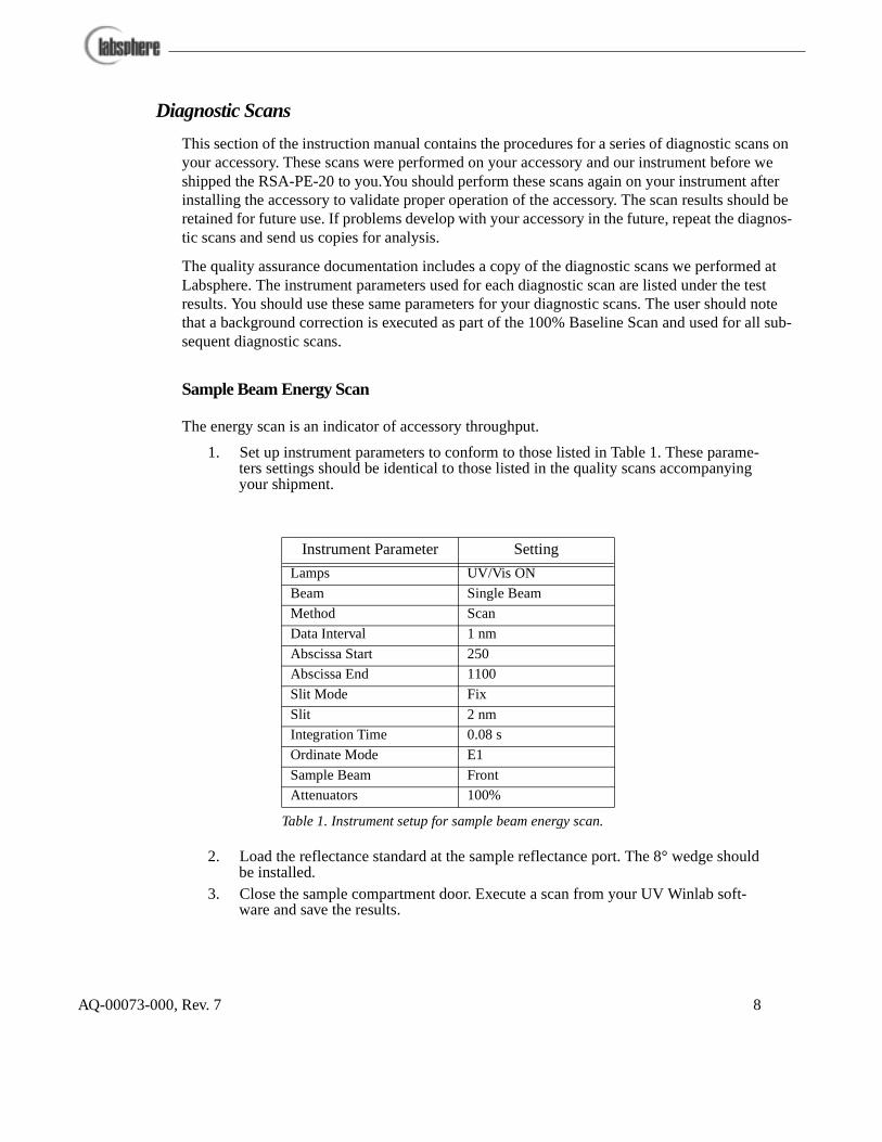
Sample Beam Energy Scan
The energy scan is an indicator of accessory throughput.
1. Set up instrument parameters to conform to those listed in Table 1. These parame-ters settings should be identical to those listed in the quality scans accompanying your shipment.
2. Load the reflectance standard at the sample reflectance port. The 8° wedge should be installed.
3. Close the sample compartment door. Execute a scan from your UV Winlab soft-ware and save the results.
Instrument Parameter Setting
Lamps UV/Vis ON
Beam Single Beam
Method Scan
Data Interval 1 nm
Abscissa Start 250
Abscissa End 1100
Slit Mode Fix
Slit 2 nm
Integration Time 0.08 s
Ordinate Mode E1
Sample Beam Front
Attenuators 100%
Table 1. Instrument setup for sample beam energy scan.
AQ-00073-000, Rev. 7 8

100% Baseline Scan
This scan provides the direct comparison of a sample scan to the baseline at the same sphere configuration. The 100% baseline scan is used for general accessory troubleshooting purposes.
1. Set up instrument parameters as listed in Table 2.
2. Load the reflectance standard at the sample reflectance port.3. Close the sample door and perform a background correction scan.4. Perform a sample scan with the same sphere configuration and save the results.
Blocked Beam Scan
The blocked beam or zeroline scan records the detector noise level from the accessory. You should use the baseline recorded during the 100% baseline scan in the previous procedure, or execute a new baseline if it is not available.
1. Set up instrument parameters as listed in Table 2. 2. Load a metal plate or other non-transmitting sample into the transmittance port.
The sample should be absorbent such that reflected light from the sample beam does is not sensed by the reference beam detector. Leave the reflectance standard at the sample reflectance port.
3. Close the sample compartment door. Execute a sample scan and save the results.
Light Trap Zeroline
The light trap scan determines if the sample beam is correctly centered on the sample reflectance port. You should use the baseline recorded during the 100% baseline scan, or execute a new baseline if it is not available.
Instrument Parameter Setting
Lamps UV/Vis ON
Beam Double Beam
Method Scan
Data Interval 1 nm
Abscissa Start 250
Abscissa End 1100
Slit Mode Fix
Slit 2 nm
Integration Time 0.08 s
Ordinate Mode %R
Sample Beam Front
Attenuators 100%/100%
Table 2. Instrument setup for the 100% Baseline Scan.
AQ-00073-000, Rev. 7 9
1. Set up instrument parameters as listed in Table 2.2. Leave the transmittance port empty and install a light trap over the sample reflec-
tance port. 3. Close the sample compartment door. Execute a sample scan and save the results.
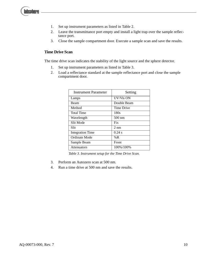
Time Drive Scan
The time drive scan indicates the stability of the light source and the sphere detector.
1. Set up instrument parameters as listed in Table 3.2. Load a reflectance standard at the sample reflectance port and close the sample
compartment door.
3. Perform an Autozero scan at 500 nm.4. Run a time drive at 500 nm and save the results.
Instrument Parameter Setting
Lamps UV/Vis ON
Beam Double Beam
Method Time Drive
Total Time 180s
Wavelength 500 nm
Slit Mode Fix
Slit 2 nm
Integration Time 0.24 s
Ordinate Mode %R
Sample Beam Front
Attenuators 100%/100%
Table 3. Instrument setup for the Time Drive Scan.
AQ-00073-000, Rev. 7 10

System Description and Operation
The RSA-PE-20 accessory is specifically designed to measure the reflectance or transmittance of solids, liquids, powders, or other small objects that can fit in the transmittance or reflectance ports. Basic components of the accessory include the integrating sphere, transfer optics and detector preamplification module. Although the RSA-PE-20 is a single beam construction, the accessory is compatible with the double beam configuration of the Lambda Series spectrometers and your UV Winlab software.
Integrating Sphere
The integrating sphere assembly, shown in Figure 7, is 50 mm in diameter and constructed of Spectralon. Spectralon is the same material used on the reflectance standard supplied with the accessory. Typical reflectance values for Spectralon are provided in Appendix B.
The RSA-PE-20 integrating sphere features two ports: a transmittance port where the beam enters the sphere, and a sample reflectance port. The illustration in Figure 7 shows the accessory integrating sphere along with the transfer optics and preamplification board. The silicon detector is mounted directly to the preamp board underneath. Two Spectralon baffles inside the sphere shield the detector sensor from direct illumination by the ports.
The sample holders, mounted either at the transmittance or sample reflectance port, clamp the
Sample Reflectance Port
Port FramePort Frame
TransmittancePort
Preamp Board
Detector Baffles
Spectralon Sphere
Detector
Figure 7. Construction of the integrating sphere.
AQ-00073-000, Rev. 7 11

reflectance standard or sample against the respective port. Three sample holders are provided with the accessory for mounting a sample either at 0° or 8° angles of incidence. The sample holders mount directly to the port frame at each end of the sphere.
The sphere detector is a silicon photodiode installed at the detector port at the bottom of the inte-grating sphere. The photodiode operates in photovoltaic mode; the detector output is conditioned by the preamplifier board for compatibility with the instrument electronics. Detailed information on the photodiode is provided in Appendix A.
Transfer Optics
The transfer optics of the RSA-PE-20 accessory direct the spectrometer sample beam to the transmittance port on the integrating sphere. The sample beam is the front beam in the accessory. As shown in Figure 6, mirrors labeled M1, M2 and M3 guide the sample beam through the sam-ple transmittance port and onto the sample reflectance port at normal incidence. All mirrors are AlMgF2 coated. Mirrors M1 and M2 are flat. Mirror M3 is a spherical mirror that condenses the sample beam onto the target sample. The reference beam passes through the accessory unim-peded.
Loading the Sample Holders
Both transmittance and sample reflectance ports are 5/8-inch holes at either end of the accessory sphere. The transmittance port is closest to mirror M3. A sample holder clamp fits over a dove-tail extension located underneath each port, securing the reflectance standard or sample tightly against the port opening.
The sample holder with the 8° wedge should be installed at the sample reflectance port when taking 8° hemispherical measurements. The 0° sample holder should be installed at the sample reflectance port when taking diffuse measurements with the specular component excluded. Fig-ure 8 describes the proper way to load the sample holder. When mounting a sample or reflec-tance standard at any port, you should make sure the reflecting surface lies flat against the wedge and completely fills the port surface area.
To remove the sample holder at the sample reflectance port, loosen the set screws along the side of the respective wedge and remove the entire sample holder assembly.
AQ-00073-000, Rev. 7 12

In some instances, you may need to load a light trap at the sample reflectance port. The light trap can be loaded using either wedge and fits into the sample holder in the same manner as a reflec-tance standard.
Theory of Operation
During the traditional measurement of sample absorption by a spectrometer, the relationship between absorptance and transmittance of the sample beam is described by the Kirchoff equa-tion:
where:
A = absorptance and
T = transmittance.
When measuring the absorptance of a sample in the sample compartment, the detector signal of the spectrometer represents the portion of the sample beam that is not absorbed or scattered by the sample.
When using the RSA-PE-20 accessory, it is convenient to use the Kirchoff relationship:
Sample or Standard
Clamp
8 Wedge
Figure 8. Loading a standard or sample into the sample holder.
A T+ 1,=
AQ-00073-000, Rev. 7 13

where R = reflectance of the sample beam at the sample surface.
During reflectance measurements, the reflected component of the sample beam is collected by the integrating sphere and detected by the sphere detector. The detector signal represents the part of the sample beam that is not transmitted and not absorbed by the sample substance.
Double Beam Spectroscopy
In a double-beam, ratio-recording spectrometer, the measurement of reflectance factor and trans-mittance involves the calculation of a baseline based upon values recorded in a background cor-rection scan. Background correction is used to compensate for changes in sphere efficiency due to the introduction of the sample into the system and for any imbalance in the energy of the sam-ple and reference beams. This correction is performed automatically by the instrument and is the same routine used during spectroscopy evolutions without the accessory. The theoretical basis for the background correction, as it applies to simple reflectance and transmittance measure-ments, is explained briefly in this section.
Radiation from the instrument illumination sources is split into two different beams: the sample beam and the reference beam. Each beam is interrupted periodically by means of an optical chopper such that the integrating sphere is illuminated alternately by the two beams. At any given wavelength, the instrument records the ratio of the signal produced by the detector when the sphere is illuminated by the sample beam to that when the reference beam is measured. Therefore, when a background correction scan is performed, for either reflectance or transmit-tance measurement, the background correction value B recorded by the instrument may be expressed as:
where:
Es is the energy of the sample beam,
Er is the energy of the reference beam,
ρs is the reflectance factor of the sample at the sample reflectance port
ρr is the reflectance factor of the reference port, and
κs and κr are the efficiency with which the energy reflected from the sample and reference beams is captured by the sphere and converted into a signal by the detector.
A T R+ + 1,=
BEsρsκs
Erρrκ r----------------= Eq. 2
AQ-00073-000, Rev. 7 14
The sphere efficiency factors (κ) for a given sample are a function of many variables including the spatial distribution of the energy reflected from the sample, the reflectance of the sphere wall, the geometry of the sphere (location of ports, baffles, etc.) and the efficiency of the detector itself. Proper measurement procedures make it possible to greatly reduce or eliminate the effect of such factors on transmittance and reflectance factor measurements.
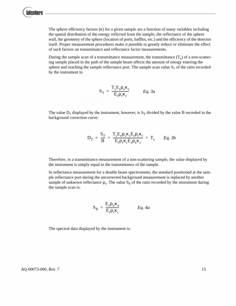
During the sample scan of a transmittance measurement, the transmittance (Ts) of a non-scatter-ing sample placed in the path of the sample beam affects the amount of energy entering the sphere and reaching the sample reflectance port. The sample scan value ST of the ratio recorded by the instrument is:
The value DT displayed by the instrument, however, is ST divided by the value B recorded in the background correction curve:
Therefore, in a transmittance measurement of a non-scattering sample, the value displayed by the instrument is simply equal to the transmittance of the sample.
In reflectance measurement for a double beam spectrometer, the standard positioned at the sam-ple reflectance port during the uncorrected background measurement is replaced by another sample of unknown reflectance ρu. The value SR of the ratio recorded by the instrument during the sample scan is:
The spectral data displayed by the instrument is:
ST
TsEsρsκ s
Erρrκ r----------------------= Eq. 3a
DT
ST
B------
TsEsρsκsErρrκ r
Erρrκ rEsρsκ s--------------------------------------- Ts= = = Eq. 3b
SR
Esρuκu
Erρrκ r-----------------= Eq. 4a
AQ-00073-000, Rev. 7 15
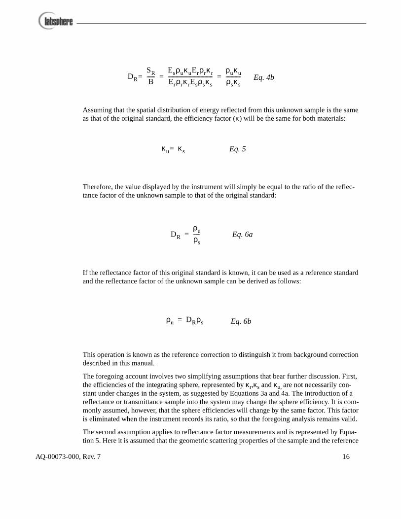
Assuming that the spatial distribution of energy reflected from this unknown sample is the same as that of the original standard, the efficiency factor (κ) will be the same for both materials:
Therefore, the value displayed by the instrument will simply be equal to the ratio of the reflec-tance factor of the unknown sample to that of the original standard:
If the reflectance factor of this original standard is known, it can be used as a reference standard and the reflectance factor of the unknown sample can be derived as follows:
This operation is known as the reference correction to distinguish it from background correction described in this manual.
The foregoing account involves two simplifying assumptions that bear further discussion. First, the efficiencies of the integrating sphere, represented by κr,κs and κu, are not necessarily con-stant under changes in the system, as suggested by Equations 3a and 4a. The introduction of a reflectance or transmittance sample into the system may change the sphere efficiency. It is com-monly assumed, however, that the sphere efficiencies will change by the same factor. This factor is eliminated when the instrument records its ratio, so that the foregoing analysis remains valid.
The second assumption applies to reflectance factor measurements and is represented by Equa-tion 5. Here it is assumed that the geometric scattering properties of the sample and the reference
DR
SR
B------=
EsρuκuErρrκ r
Erρrκ rEsρsκs----------------------------------
ρuκu
ρsκ s-----------= = Eq. 4b
κu κ s= Eq. 5
DR
ρu
ρs-----= Eq. 6a
ρu DRρs= Eq. 6b
AQ-00073-000, Rev. 7 16

standard are identical. Therefore, the efficiency factor for radiation reflected from each sample will be the same. If the geometric scattering properties of the sample differ greatly from those of the reference, significant systematic errors may be introduced into the measurements. Therefore, the geometric scattering properties of the sample and the reference should be matched as closely as possible.
Although your PerkinElmer spectrometer may be a double beam instrument, the RSA-PE-20 is a single beam accessory such that combined operation is in dual beam spectrometer mode. The value of κr for your system does not change from background correction to sample scan.
Single Beam Substitution Error Correction
The single beam substitution error, sometimes known as single beam sample absorption error, is the systematic, predictable, and non-random error inherent in single beam integrating spheres measuring reflectance or transmittance. The error is caused by the difference in the throughput of the sphere when the reference makes up a portion of the sphere wall and when the sample is substituted for the reference. In integrating spheres which are designed for dual beam spectrom-eters, it is not possible to place both the reference beam and the sample beam into the sphere at the same time. These dual beam spectrometers employ a beamsplitter to divide the instrument’s beam between the sample and reference channels.
Thus, even though the dual beam spectrometer has two beams, it is still only possible to utilize a single beam integrating sphere accessory. Unfortunately, single beam integrating spheres are subject to substitution errors during sample measurements which must be corrected to obtain accurate results.
In reflectance measurements the throughput and corresponding measured reflectance is usually lower when the sample is present since a reference material of high reflectance is used. In trans-mittance measurements the throughput and the measured transmittance is usually higher when the sample is present since an open port is typically used as a reference. With spectrometers that
����������������������������
PhysicalReference
����������������������������
Reference Detector (optional)
Sample Beam
Reference Beam
����������������
Sample
������������������������������
Reference Detector (optional)
Sample Beam
Reference Beam
Background Scan Sample Scan
Figure 9. Operation of a dual beam spectrometer.
AQ-00073-000, Rev. 7 17

use a chopped signal between sample and reference, this error does not occur. Double beam spectrometers are able to accept double beam integrating spheres in which both the sample and reference beams are placed in the sphere. Double beam spectrometers employ a chopper to divide the instrument beam between the sample, reference, and dark channels. Although your spectrometer is a double instrument, the RSA-PE-20 is designed as a single beam accessory to accommodate the size of the instrument sample compartment. Since only the sample beam is subject to sphere configuration, your RSA-PE-20 measurements are subject to substitution error.
When a sample and a reference are of similar reflectance, the substitution correction is very small; at worst it may reach as much as 4 - 5%. In quality control applications where a threshold value is used, this may not be a concern, as the error can simply be built into the threshold. This is also true if only peak position information is required, as single beam correction only concerns the photometric scale.
There are both physical and mathematical solutions to the problem of single beam substitution error. If the sphere is made sufficiently large and the area of the sample is minimized, the error increasingly diminishes. The use of a large sphere is usually not practical in low cost spectropho-tometer systems due to signal-to-noise concerns as well a price considerations. The integrating sphere on your RSA-PE-20 accessory is too small to accommodate the modifications necessary for a physical solution.
The mathematical solution is simple in theory, but complex in practice. If a reference is used that is very close in reflectance to the reflectance of the sample, the substitution error becomes negli-gible. If the user can match the reference reflectance to the reflectance of the sample, or has a large database of different level photometric reflectance standards, one can set up look-up or cor-rection tables to correct for the substitution error.
Tables 4 and 5 show reflectance values for twelve levels of photometric gray scale. Table 4 pro-vides data for gray Spectralon exhibiting diffuse reflectance characteristics under 50%. Table 5 provides the data for Spectralon reflectances greater than 50%. The italicized values are the actual reflectance of samples of Labsphere SRS-XX gray scale reflectance material. These reflectance values were determined by measuring the corrected 8°/ hemispherical reflectance factors using a Labsphere double beam spectrometer and a double beam accessory with a 150 mm diameter integrating sphere. The second set of reflectance values in regular print were mea-sured on a spectrometer equipped with a Labsphere 50 mm single beam integrating sphere accessory.
AQ-00073-000, Rev. 7 18

To use the tables, look at the wavelength of interest and find the value under the column marked L2 corresponding as close as possible to sample reflectance you measured with your single beam accessory. These values were determined with a PerkinElmer Lambda 2 double beam spectrom-eter and an RSA-PE-20 single beam accessory. Compare the charted L2 value and your mea-sured reflectance to the reflectance value under the column marked L19 immediately to its left. The value under L19 is the actual value of reflectance of the sample at that wavelength - you may need to interpolate. These values were determined with a Lambda 19 spectrometer and RSA-PE-19 double beam accessory. The standards used in generating these tables were spec-trally flat over a wide wavelength range. Supplemental information is available for some materi-als along with the slope in their reflectance curves. This technique is the same used for measurements of standards at the National Institute of Standards and Technology (NIST), the National Physical Laboratory (NPL) and the National Research Council Canada (NRCC). The data is available at Labsphere on disk. Be advised that these tables should used for diffusely reflecting materials only.
3 0 0 0.009 0 .0 11 0 .0 53 0 .0 6 5 0.09 9 0 .1 2 3 0 .19 2 0 .2 3 1 0.33 7 0 .3 9 4 0 .3 78 0 .4 3 63 2 5 0.009 0 .0 11 0 .0 50 0 .0 6 4 0.09 5 0 .1 2 1 0 .18 8 0 .2 3 0 0.32 9 0 .3 9 2 0 .3 71 0 .4 3 43 5 0 0.009 0 .0 1 2 0 .0 50 0 .0 6 4 0.09 3 0 .1 2 1 0 .18 4 0 .2 3 0 0.32 3 0 .3 8 8 0 .3 66 0 .4 3 23 7 5 0.009 0 .0 11 0 .0 49 0 .0 6 4 0.09 2 0 .1 2 2 0 .18 2 0 .2 2 9 0.31 9 0 .3 8 7 0 .3 62 0 .4 3 14 0 0 0.010 0 .0 11 0 .0 48 0 .0 6 4 0.09 1 0 .1 2 2 0 .18 1 0 .2 3 0 0.31 6 0 .3 8 6 0 .3 60 0 .4 3 14 2 5 0.010 0 .0 11 0 .0 48 0 .0 6 4 0.09 1 0 .1 2 2 0 .18 1 0 .2 3 1 0.31 4 0 .3 8 5 0 .3 59 0 .4 3 14 5 0 0.010 0 .0 11 0 .0 48 0 .0 6 4 0.09 1 0 .1 2 2 0 .18 2 0 .2 3 2 0.31 3 0 .3 8 5 0 .3 58 0 .4 3 24 7 5 0.010 0 .0 11 0 .0 49 0 .0 6 4 0.09 1 0 .1 2 2 0 .18 3 0 .2 3 3 0.31 3 0 .3 8 5 0 .3 59 0 .4 3 35 0 0 0.010 0 .0 11 0 .0 49 0 .0 6 4 0.09 2 0 .1 2 3 0 .18 4 0 .2 3 5 0.31 3 0 .3 8 5 0 .3 59 0 .4 3 35 2 5 0.010 0 .0 11 0 .0 50 0 .0 6 5 0.09 2 0 .1 2 3 0 .18 6 0 .2 3 6 0.31 3 0 .3 8 5 0 .3 60 0 .4 3 45 5 0 0.010 0 .0 11 0 .0 50 0 .0 6 5 0.09 3 0 .1 2 3 0 .18 7 0 .2 3 8 0.31 3 0 .3 8 5 0 .3 61 0 .4 3 55 7 5 0.010 0 .0 11 0 .0 50 0 .0 6 6 0.09 3 0 .1 2 4 0 .18 8 0 .2 3 9 0.31 4 0 .3 8 6 0 .3 62 0 .4 3 66 0 0 0.010 0 .0 11 0 .0 51 0 .0 6 6 0.09 4 0 .1 2 4 0 .19 0 0 .2 4 0 0.31 5 0 .3 8 6 0 .3 64 0 .4 3 66 2 5 0.010 0 .0 11 0 .0 51 0 .0 6 6 0.09 5 0 .1 2 5 0 .19 1 0 .2 4 1 0.31 6 0 .3 8 6 0 .3 65 0 .4 3 66 5 0 0.011 0 .0 11 0 .0 52 0 .0 6 7 0.09 5 0 .1 2 5 0 .19 3 0 .2 4 3 0.31 7 0 .3 8 6 0 .3 66 0 .4 3 76 7 5 0.011 0 .0 11 0 .0 52 0 .0 6 7 0.09 6 0 .1 2 6 0 .19 4 0 .2 4 3 0.31 7 0 .3 8 6 0 .3 67 0 .4 3 77 0 0 0.011 0 .0 11 0 .0 53 0 .0 6 8 0.09 7 0 .1 2 6 0 .19 5 0 .2 4 5 0.31 8 0 .3 8 7 0 .3 68 0 .4 3 87 2 5 0.011 0 .0 11 0 .0 54 0 .0 6 8 0.09 8 0 .1 2 7 0 .19 6 0 .2 4 5 0.31 9 0 .3 8 8 0 .3 69 0 .4 3 97 5 0 0.011 0 .0 11 0 .0 54 0 .0 6 8 0.09 9 0 .1 2 7 0 .19 8 0 .2 4 6 0.32 0 0 .3 8 8 0 .3 70 0 .4 4 07 7 5 0.012 0 .0 11 0 .0 55 0 .0 6 9 0.10 0 0 .1 2 8 0 .19 9 0 .2 4 7 0.32 1 0 .3 8 8 0 .3 71 0 .4 4 08 0 0 0.012 0 .0 11 0 .0 56 0 .0 6 9 0.10 1 0 .1 2 9 0 .20 0 0 .2 4 9 0.32 3 0 .3 9 1 0 .3 72 0 .4 4 08 2 5 0.012 0 .0 11 0 .0 57 0 .0 7 0 0.10 2 0 .1 3 0 0 .20 2 0 .2 4 9 0.32 4 0 .3 9 1 0 .3 74 0 .4 4 28 5 0 0.013 0 .0 11 0 .0 57 0 .0 7 1 0.10 2 0 .1 3 1 0 .20 3 0 .2 5 1 0.32 5 0 .3 9 1 0 .3 75 0 .4 4 28 7 5 0.013 0 .0 1 2 0 .0 58 0 .0 7 2 0.10 4 0 .1 3 2 0 .20 4 0 .2 5 1 0.32 6 0 .3 9 1 0 .3 76 0 .4 4 29 0 0 0.013 0 .0 1 2 0 .0 59 0 .0 7 2 0.10 4 0 .1 3 3 0 .20 6 0 .2 5 2 0.32 7 0 .3 9 1 0 .3 77 0 .4 4 19 2 5 0.014 0 .0 1 2 0 .0 59 0 .0 7 2 0.10 5 0 .1 3 3 0 .20 7 0 .2 5 2 0.32 8 0 .3 9 1 0 .3 78 0 .4 4 19 5 0 0.014 0 .0 1 2 0 .0 60 0 .0 7 2 0.10 6 0 .1 3 4 0 .20 8 0 .2 5 2 0.32 9 0 .3 9 1 0 .3 79 0 .4 4 29 7 5 0.014 0 .0 1 3 0 .0 61 0 .0 7 3 0.10 7 0 .1 3 4 0 .20 9 0 .2 5 4 0.33 1 0 .3 9 2 0 .3 80 0 .4 4 3
1 0 0 0 0.014 0 .0 1 2 0 .0 61 0 .0 7 3 0.10 8 0 .1 3 5 0 .21 0 0 .2 5 5 0.33 2 0 .3 9 2 0 .3 81 0 .4 4 31 0 2 5 0.014 0 .0 1 2 0 .0 62 0 .0 7 5 0.10 8 0 .1 3 5 0 .21 0 0 .2 5 6 0.33 3 0 .3 9 3 0 .3 82 0 .4 4 31 0 5 0 0.014 0 .0 1 2 0 .0 62 0 .0 7 5 0.10 9 0 .1 3 5 0 .211 0 .2 5 6 0.33 4 0 .3 9 2 0 .3 83 0 .4 4 41 0 7 5 0.014 0 .0 1 2 0 .0 62 0 .0 7 5 0.11 0 0 .1 3 6 0 .21 2 0 .2 5 7 0.33 4 0 .3 9 4 0 .3 83 0 .4 4 41 1 0 0 0.015 0 .0 1 2 0 .0 63 0 .0 7 6 0.11 0 0 .1 3 8 0 .21 3 0 .2 5 7 0.33 6 0 .3 9 6 0 .3 85 0 .4 4 5
Wavelength Gray0/L2 Gray0/L19 Gray4/L2 Gray4/L19 Gray5/L2 Gray5/L19 Gray7/L2 Gray7/L19 Gray10/L2 Gray10/L19 Gray11/L2 Gray11/L19
Table 4. Reflectance values for gray Spectralon under 50%R.
AQ-00073-000, Rev. 7 19

An example of the use of these tables is shown in Appendix C. In these measurements, Lab-sphere SCS Spectralon color standards were measured using a dual beam spectrometer with a single beam sphere accessory and a double beam spectrometer with a double beam sphere acces-sory. The samples were chosen based on their wide reflectance variation across the wavelength spectrum. In each case, the bottom curve represents the measured spectrum generated on the sin-gle beam sphere. The ‘boxed’ curve represents the corrected values using the lookup tables. The light curve is the actual reflectance of the standard as measured on the Lambda 19. The corrected values, using the Substitution Error Correction Tables, give an excellent correlation with actual double beam measurements.
Zeroline Correction
An integrating sphere is sensitive to small-angle scatter from the sample beam coupling optics. The scattered radiation strikes the wall of the integrating sphere near the sample reflectance port, creating a "halo" surrounding the port. This "halo-effect" gives rise to a small error in measure-ment of reflectance factor which is most significant when measuring samples of very low reflec-tance. Fortunately, this error is relatively easy to characterize and correct. The following procedure may be used to correct reflectance factor measurements of diffuse or specular sam-ples, in either the 8°/Hemispherical or 0°/Diffuse geometries:
3 0 0 0.51 2 0 .5 7 1 0.6 36 0 .6 9 1 0.7 30 0 .7 7 3 0.79 1 0 .8 2 5 0.89 5 0 .9 1 2 0.95 6 0 .9 6 43 2 5 0.50 5 0 .5 7 1 0.6 31 0 .6 9 1 0.7 25 0 .7 7 4 0.79 2 0 .8 2 7 0.89 8 0 .9 1 5 0.96 5 0 .9 7 13 5 0 0.50 0 0 .5 6 9 0.6 27 0 .6 9 2 0.7 22 0 .7 7 5 0.79 0 0 .8 2 9 0.89 9 0 .9 1 7 0.97 0 0 .9 7 53 7 5 0.49 5 0 .5 6 8 0.6 24 0 .6 9 1 0.7 18 0 .7 7 1 0.78 9 0 .8 2 7 0.89 8 0 .9 1 7 0.97 4 0 .9 7 84 0 0 0.49 2 0 .5 6 8 0.6 23 0 .6 9 2 0.7 16 0 .7 7 4 0.78 9 0 .8 3 2 0.89 9 0 .9 1 8 0.97 8 0 .9 8 34 2 5 0.49 1 0 .5 6 7 0.6 22 0 .6 9 3 0.7 15 0 .7 7 5 0.79 0 0 .8 3 3 0.89 9 0 .9 1 8 0.98 0 0 .9 8 54 5 0 0.49 0 0 .5 6 8 0.6 23 0 .6 9 3 0.7 14 0 .7 7 4 0.79 1 0 .8 3 3 0.90 0 0 .9 2 0 0.98 1 0 .9 8 64 7 5 0.49 1 0 .5 6 8 0.6 24 0 .6 9 5 0.7 15 0 .7 7 5 0.79 3 0 .8 3 5 0.90 2 0 .9 2 1 0.98 3 0 .9 8 75 0 0 0.49 1 0 .5 6 9 0.6 24 0 .6 9 6 0.7 15 0 .7 7 6 0.79 4 0 .8 3 6 0.90 2 0 .9 2 1 0.98 3 0 .9 8 75 2 5 0.49 2 0 .5 7 0 0.6 26 0 .6 9 6 0.7 16 0 .7 7 5 0.79 5 0 .8 3 7 0.90 3 0 .9 2 2 0.98 3 0 .9 8 85 5 0 0.49 3 0 .5 7 0 0.6 27 0 .6 9 8 0.7 16 0 .7 7 7 0.79 7 0 .8 3 9 0.90 4 0 .9 2 1 0.98 3 0 .9 8 85 7 5 0.49 5 0 .5 7 0 0.6 28 0 .6 9 8 0.7 17 0 .7 7 6 0.79 8 0 .8 4 0 0.90 5 0 .9 2 4 0.98 3 0 .9 8 76 0 0 0.49 6 0 .5 7 1 0.6 29 0 .6 9 8 0.7 18 0 .7 7 6 0.80 0 0 .8 4 0 0.90 6 0 .9 2 3 0.98 3 0 .9 8 86 2 5 0.49 7 0 .5 7 2 0.6 31 0 .6 9 9 0.7 19 0 .7 7 7 0.80 2 0 .8 4 1 0.90 7 0 .9 2 4 0.98 3 0 .9 8 76 5 0 0.49 8 0 .5 7 2 0.6 32 0 .6 9 9 0.7 19 0 .7 7 6 0.80 3 0 .8 4 1 0.90 7 0 .9 2 6 0.98 3 0 .9 8 86 7 5 0.49 9 0 .5 7 2 0.6 33 0 .7 0 1 0.7 20 0 .7 7 7 0.80 5 0 .8 4 3 0.90 8 0 .9 2 4 0.98 3 0 .9 8 87 0 0 0.50 0 0 .5 7 4 0.6 34 0 .7 0 2 0.7 21 0 .7 7 8 0.80 6 0 .8 4 3 0.90 9 0 .9 2 5 0.98 3 0 .9 8 87 2 5 0.50 1 0 .5 7 5 0.6 35 0 .7 0 2 0.7 21 0 .7 7 6 0.80 7 0 .8 4 4 0.91 0 0 .9 2 6 0.98 3 0 .9 8 87 5 0 0.50 3 0 .5 7 6 0.6 37 0 .7 0 3 0.7 22 0 .7 7 8 0.80 9 0 .8 4 5 0.911 0 .9 2 6 0.98 3 0 .9 8 87 7 5 0.50 4 0 .5 7 5 0.6 38 0 .7 0 4 0.7 23 0 .7 7 8 0.81 0 0 .8 4 6 0.91 2 0 .9 2 6 0.98 4 0 .9 8 78 0 0 0.50 6 0 .5 7 6 0.6 40 0 .7 0 4 0.7 24 0 .7 7 7 0.81 2 0 .8 4 6 0.91 3 0 .9 3 1 0.98 4 0 .9 9 08 2 5 0.50 7 0 .5 7 8 0.6 41 0 .7 0 4 0.7 25 0 .7 7 7 0.81 3 0 .8 4 8 0.91 3 0 .9 3 0 0.98 3 0 .9 8 88 5 0 0.50 8 0 .5 7 8 0.6 42 0 .7 0 4 0.7 25 0 .7 7 7 0.81 3 0 .8 4 8 0.91 3 0 .9 3 0 0.98 2 0 .9 9 08 7 5 0.50 9 0 .5 7 8 0.6 44 0 .7 0 5 0.7 26 0 .7 7 8 0.81 4 0 .8 4 8 0.91 2 0 .9 2 9 0.98 1 0 .9 8 89 0 0 0.511 0 .5 7 8 0.6 45 0 .7 0 6 0.7 26 0 .7 7 9 0.81 4 0 .8 5 1 0.91 2 0 .9 3 0 0.98 0 0 .9 8 89 2 5 0.51 2 0 .5 7 9 0.6 46 0 .7 0 7 0.7 27 0 .7 8 1 0.81 5 0 .8 5 1 0.91 3 0 .9 3 0 0.98 0 0 .9 8 79 5 0 0.51 3 0 .5 7 9 0.6 47 0 .7 0 9 0.7 28 0 .7 8 1 0.81 7 0 .8 5 1 0.91 4 0 .9 3 0 0.98 0 0 .9 8 89 7 5 0.51 5 0 .5 7 9 0.6 48 0 .7 1 0 0.7 28 0 .7 8 1 0.81 8 0 .8 5 1 0.91 4 0 .9 3 1 0.98 1 0 .9 8 9
1 0 0 0 0.51 6 0 .5 7 9 0.6 50 0 .7 1 0 0.7 30 0 .7 8 2 0.82 0 0 .8 5 4 0.91 6 0 .9 3 1 0.98 1 0 .9 8 81 0 2 5 0.51 7 0 .5 8 0 0.6 51 0 .7 11 0.7 30 0 .7 8 1 0.82 1 0 .8 5 4 0.91 7 0 .9 3 2 0.98 2 0 .9 8 61 0 5 0 0.51 7 0 .5 8 0 0.6 52 0 .7 1 2 0.7 29 0 .7 8 1 0.81 8 0 .8 5 5 0.91 2 0 .9 3 2 0.97 6 0 .9 8 81 0 7 5 0.51 8 0 .5 8 2 0.6 52 0 .7 1 3 0.7 28 0 .7 8 3 0.81 6 0 .8 5 4 0.90 9 0 .9 3 1 0.97 1 0 .9 8 61 1 0 0 0.51 9 0 .5 8 1 0.6 54 0 .7 1 4 0.7 29 0 .7 8 3 0.81 7 0 .8 5 6 0.91 0 0 .9 3 2 0.97 2 0 .9 8 8
Wavelength Gray14/L2 Gray14/L19 Gray16/L2 Gray16/L19 Gray18/L2 Gray18/L19 Gray20/L2 Gray20/L19 Gray22/L2 Gray22/L19 Gray23/L2 Gray23/L19
Table 5. Reflectance values for gray Spectralon over 50%R.
AQ-00073-000, Rev. 7 20

1. Perform a reflectance factor measurement of a given sample as described in the operating procedures.
2. Replace the sample with a light trap. The reflectance of the light trap is approxi-mately 0%.
3. Execute a sample scan to record the measurement data on the light trap.4. Compute the corrected reflectance factor for the sample, ρs, as follows:
where:ρr = the reflectance value of the reference standard,
R = the sample data displayed on the instrument expressed in percent, and
Z = the data from the light trap measurement, expressed in percent.
Note: This zero-correction procedure can also be used in conjunction with a mask at the sample reflectance port to accurately measure the reflectance factor of samples smaller than the sample port dimensions.
Operating Procedures for the RSA-PE-20 Accessory
The RSA-PE-20 accessory can measure reflectance factors at either 0° or 8° angles of incidence. The angle of incidence is controlled by the sample holder configuration at the sample reflectance port. You should keep in mind, however, that 8° hemispherical measurements will include the specular component reflecting off the sample surface. Although calibrations using the 0° geome-try are available on a custom basis, the standard calibrations at Labsphere are performed at 8°. If your application requires NIST traceability, you should use a calibrated reflectance standard and the 8° reflectance geometry.
Since any integrating sphere accessory acts as a signal attenuator, you should run scans at a slower scan speed than in ordinary transmittance work without the accessory, or increase the integration time if collecting data at a fixed wavelength.
8°/Hemispherical Reflectance Factor Measurements
Hemispherical reflectance measurements can be made on diffuse or specular samples - the pro-cedure is the same. If you are measuring a specular sample, a specular reference standard, such as a calibrated first-surface aluminum mirror, should be substituted for the diffuse reference standard.
1. Secure the 8° reflectance sample holder over the reflectance sample port.2. Load a calibrated or uncalibrated reflectance standard at the sample reflectance
port.
ρs
R Z–( )ρr
100 Z–( )-----------------------=
AQ-00073-000, Rev. 7 21

3. Choose your reflectance sample method from the UV Winlab software or manually set all instrument parameters as desired.
4. Perform a background correction scan.5. Replace the reflectance standard at the sample reflectance port with your sample. 6. Execute a sample scan and save the scan data.7. Multiply the values recorded in the resulting scan by the known spectral reflectance
factor values of the reflectance standard to determine the actual reflectance of the sample. If your reflectance standard is an uncalibrated USRS-99-010 from Lab-sphere, you can use the reflectance data in Appendix B.
0°/Hemispherical Reflectance Factor Measurements
The integrating sphere of the accessory has two sample holders for the sample reflectance port. The standard sample holder is designed to position the sample for illumination by the sample beam at an 8° incident angle. The second sample holder is designed for normal, 0° incidence. With the 0° sample holder in place, any specular component of reflection from the sample is excluded from measurement, since this component is directed out of the sphere through the transmittance sample entrance port. Therefore, the 0° sample holder may be used to make 0°/d reflectance factor measurements. The procedure for such measurement is as follows:
1. Remove the 8° sample holder from the reflectance sample port and install the 0° sample holder.
2. Load a diffuse reflectance standard at the sample port.3. Choose your reflectance sample method from the UV Winlab software or manually
set all instrument parameters as desired.4. Perform a background correction scan.5. Replace the reflectance standard at the sample reflectance port with your sample. 6. Execute a sample scan and save the scan data.7. Multiply the values recorded in the resulting scan by the known spectral reflectance
factor values of the reflectance standard to determine the actual reflectance of the sample. If your reflectance standard is an uncalibrated USRS-99-010 from Lab-sphere, you can use the reflectance data in Appendix B.
Note: Measurements performed using the specular excluded geometry should always be interpreted with caution. The transmittance port may not be completely effective in remov-ing the specular reflection component.
Reflectance Measurement of Non-Ideal Samples
Two simple ideal geometric reflectance distributions may be described: perfect specular reflec-tion, and perfect diffuse reflection. Perfect specular reflection is simply reflection according to Fresnel's law, without scattering. Perfect diffuse reflection is reflection according to Lambert's law. For the purposes of integrating-sphere-based reflectometry, the Spectralon standards pro-vided with this accessory serve as an excellent approximation to the ideal of perfect Lambertian reflection, while a clean, flat, first-surface mirror provides an excellent approximation to the
AQ-00073-000, Rev. 7 22
ideal of perfect specular reflection.
If your sample approaches perfection, in either diffuse or specular reflectance distribution, your scan data using the procedure above will be accurate. If your sample is not perfectly specular or diffuse, you may decide simply to measure the sample as if it were either nearly specular or Lambertian, accepting the fact that such measurements involve a higher-than-ordinary degree of systematic uncertainty. Such an approach is more than adequate for many applications, espe-cially those in which the emphasis is on repeatability rather than absolute accuracy of measure-ment. Another alternative might be to scan the sample at the 8° geometry using the diffuse and specular standards, and take the average reflectance of the two.
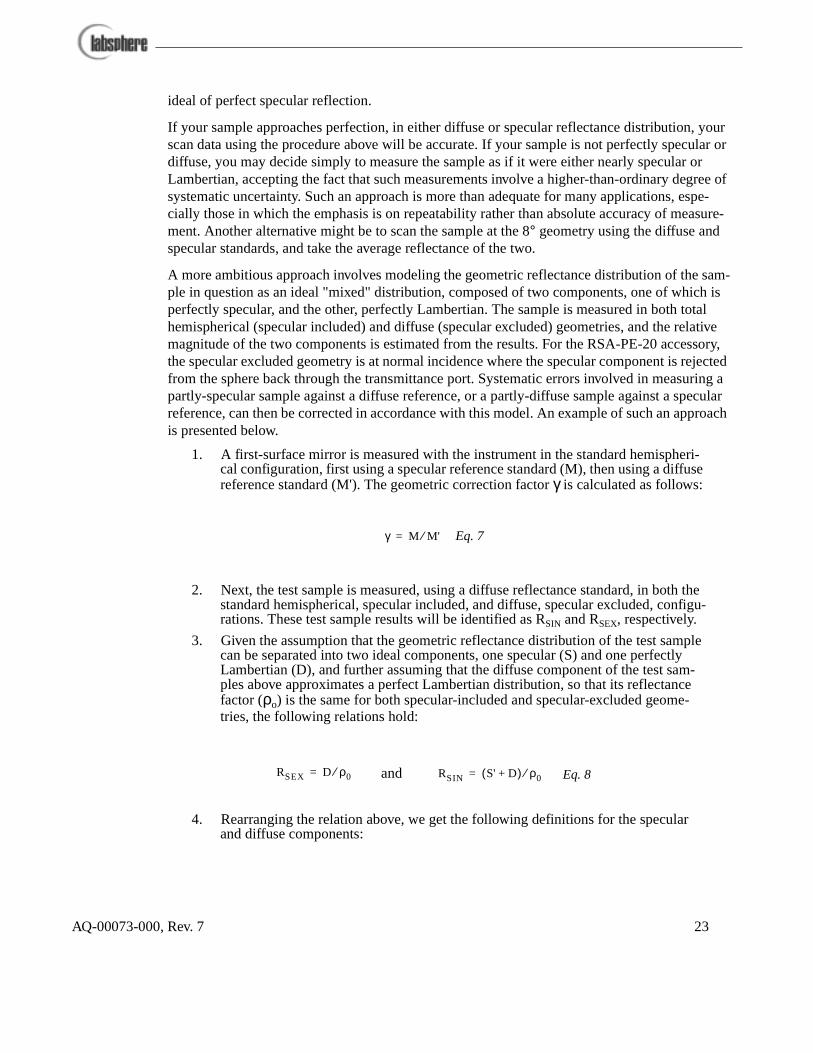
A more ambitious approach involves modeling the geometric reflectance distribution of the sam-ple in question as an ideal "mixed" distribution, composed of two components, one of which is perfectly specular, and the other, perfectly Lambertian. The sample is measured in both total hemispherical (specular included) and diffuse (specular excluded) geometries, and the relative magnitude of the two components is estimated from the results. For the RSA-PE-20 accessory, the specular excluded geometry is at normal incidence where the specular component is rejected from the sphere back through the transmittance port. Systematic errors involved in measuring a partly-specular sample against a diffuse reference, or a partly-diffuse sample against a specular reference, can then be corrected in accordance with this model. An example of such an approach is presented below.
1. A first-surface mirror is measured with the instrument in the standard hemispheri-cal configuration, first using a specular reference standard (M), then using a diffuse reference standard (M'). The geometric correction factor γ is calculated as follows:
2. Next, the test sample is measured, using a diffuse reflectance standard, in both the standard hemispherical, specular included, and diffuse, specular excluded, configu-rations. These test sample results will be identified as RSIN and RSEX, respectively.
3. Given the assumption that the geometric reflectance distribution of the test sample can be separated into two ideal components, one specular (S) and one perfectly Lambertian (D), and further assuming that the diffuse component of the test sam-ples above approximates a perfect Lambertian distribution, so that its reflectance factor (ρo) is the same for both specular-included and specular-excluded geome-tries, the following relations hold:
4. Rearranging the relation above, we get the following definitions for the specular and diffuse components:
γ M M'⁄= Eq. 7
RSEX D ρ0⁄= RSIN S' D+( ) ρ0⁄=and Eq. 8
AQ-00073-000, Rev. 7 23

where S' represents the contribution of the specular component of the test sample to the apparent hemispherical reflectance factor of the sample. This quantity is analo-gous to the value M' given in Eq. 7 and its relation to the actual specular component of hemispherical reflectance (S) is described in Eq. 10:
5. On this analysis, the best estimate for the 8°/hemispherical reflectance factor of the test sample (RT), is given as follows:
Transmittance Measurements
ASTM E 179-91a describes three categories of transmittance measurement: regular transmit-tance, diffuse transmittance, and total transmittance. These three terms relate to each other in the same fashion as regular or specular, diffuse and total reflectance. Regular transmittance is the ratio of the undiffused transmitted flux to the incident flux. Diffuse transmittance is the ratio of transmitted flux measured at all forward angles except the regular transmittance angle, to the incident flux. Total transmittance is the ratio of flux transmittance at all forward angles to the incident flux. An illustrative description from ASTM E 179-91a is shown in Figure 10.
D RSEXρ0= S' RSIN RSEX–( ) ρ0⁄=and Eq. 9
S γS' γ RSIN RSEX–( )ρ0== Eq. 10
RT S D+ γRSIN 1 γ–( )RSEX+( )ρ0= = Eq. 11
Regular Transmittance
Impinging Light Beam Retroreflection
Specular Reflection
Diffuse Reflectance
Diffuse Transmittance
Figure 10. Components of reflectance and transmittance phenomena.
AQ-00073-000, Rev. 7 24

The following procedure can be used to measure total transmittance of a sample.
1. Load a diffuse reflectance standard at the sample reflectance port.2. If you are scanning a liquid sample, load an empty cuvette into the cuvette holder,
and load the entire cuvette holder assembly at the transmittance port. Otherwise, leave the transmittance port empty.
3. Choose your transmittance sample method from the UV Winlab software or manu-ally set all instrument parameters as desired.
4. Perform a background correction scan.5. Load your sample at the transmittance port. If you are measuring a liquid, replace
the empty cuvette with your sample cuvette. 6. Execute a sample scan and save the scan data.7. The value displayed by the instrument is the sample transmittance.
Note: When measuring the transmittance of large samples, make sure that the reference or sample beam is not obscured by any part of the sample, and that the sample compartment lid closes completely.
The procedure here for total transmittance measurement will produce accurate results for non-scattering samples. For transmittance samples exhibiting high degree of scattering, the scan results will be instrument-specific.
You can measure the diffuse transmittance of a test sample using the following procedure:
1. Perform a background correction scan on the accessory with a diffuse reflectance standard loaded at the sample reflectance port, and an empty cuvette, if used, fitted in front of the transmittance port.
2. Replace the reflectance standard at the sample reflectance port with a light-trap. This light trap will capture and exclude from measurement the undiffused portion of the flux transmitted by the sample.
3. Load the test sample or sample cuvette at the transmittance port and execute a sam-ple scan.
An approximate regular transmittance of a sample can be determined by measuring the total and diffuse transmittance, as described above, and subtracting the diffuse component from the total transmittance.
AQ-00073-000, Rev. 7 25
Maintenance
General Information
When not in use, the accessory should be stored in the antistatic bag provided in a controlled environment. Dust and moisture may adversely affect its performance. Take the following pre-cautions when using your RSA-PE-20 accessory:
• Never disconnect or connect the detector cable with the instrument powered ON
• Do not handle the mirrors without gloves • Do not allow foreign objects to enter the integrating sphere • Clean dust and particulate debris out of the sphere using a gentle stream of
clean air.
Mirror Cleaning Procedure
The transfer optic mirrors should never be touched or handled without the benefit of gloves. The mirrors have a protective magnesium fluoride overcoat to allow cleaning if necessary. The fol-lowing cleaning procedure is recommended:
1. Spray the mirror with Fantastic Spray Cleaner.2. Rinse the mirror with distilled water.3. Repeat until the water sheets off the mirror.4. Blow dry with a stream of clean nitrogen.
Spectralon Cleaning Instructions
In order to maintain the unique optical and reflectance properties of Spectralon standards, keep the surfaces of the material very clean. Should Spectralon become soiled, particles may be blown off it with a jet of clean air. If this is insufficient, sand the piece with a 220-240 grit emery cloth under a stream of running water. Sand the surface until it is totally hydrophobic (water beads and runs off immediately) and then shake off water droplets, or blow them off with a stream of clean air. You will have to disassemble the integrating sphere to do this.
Note: Ordinary compressed air systems typically carry microscopic oil droplets that may con-taminate Spectralon.
AQ-00073-000, Rev. 7 26

Appendix A Specifications
Dimensions 10" x 4.5" x 5"
Weight 4 lbs
Spectral Range 190 - 1100 nm
Integrating Sphere
Construction Spectralon
Sphere Diameter 50 mm (2")
Transmittance Port 5/8"
Reflectance Port 5/8"
Detector Hamamatsu S1227-66BQ
AQ-00073-000, Rev. 7 27

Appendix B Typical Spectralon Reflectance Values
Wavelength Spectralon 8° Hemispherical Reflectance
250 .973
300 .984
400 .991
500 .991
600 .992
700 .992
800 .991
900 .991
1000 .993
1100 .993
1200 .992
1300 .993
1400 .991
1500 .992
1600 .992
1700 .988
1800 .989
1900 .981
2000 .976
2100 .953
2200 .973
2300 .972
2400 .955
2500 .960
AQ-00073-000, Rev. 7 28
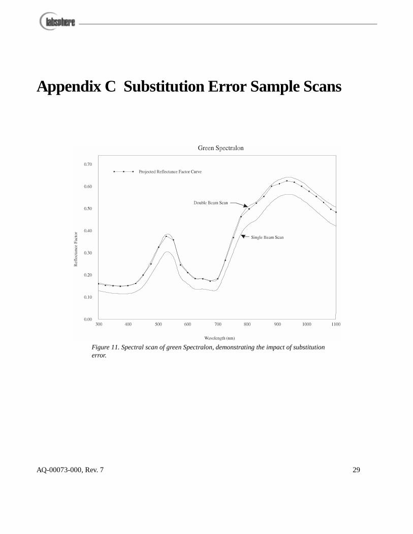
Appendix C Substitution Error Sample Scans
Figure 11. Spectral scan of green Spectralon, demonstrating the impact of substitution error.
AQ-00073-000, Rev. 7 29

Figure 12. Spectral scans of blue and red Spectralon samples.
AQ-00073-000, Rev. 7 30

Appendix D Reflectance Glossary
Diffuse Reflection. Reflection in which flux is scattered in many directions by diffusion at or below the surface.
Diffuse Transmittance. Ratio of the flux transmitted by a specimen to the incident flux, the trans-mitted flux being measured for all forward angles except the regular transmittance angle.
Diffusion. Change of the angular distribution of a beam of radiant flux by a transmitting material or a reflecting surface such that flux incident in one direction is continuously distributed in many directions, the process not conforming (on a macroscopic scale) to the laws of Fresnel (regular) reflection and refraction and there being no change in frequency (wavelength) of the monochro-matic components of the flux.
Lambertian Diffuser. Ideal surface that reflects or transmits radiation completely in accord with Lambert's cosine law. When illuminated from any direction, its radiance is the same for every direction of view.
Lambert's law. The intensity (flux per unit solid angle) emitted in any direction from a surface var-ies as the cosine of the angle between the normal to the surface and the direction of the emitted flux (also called Lambert's cosine law).
Mixed Reflection. Partly specular and partly diffuse reflection.
Mixed Transmission. A combination of diffuse and regular transmission.
Perfect Reflecting Diffuser. Ideal reflecting surface that neither absorbs nor transmits light, but reflects diffusely, with the radiance of the reflecting surface being the same for all reflecting angles, regardless of the angular distribution of the incident light.
Perfect Transmitting Diffuser. Ideal transmitting specimen that neither absorbs nor reflects light, but transmits diffusely, with the radiance of the specimen being the same for all transmitting angles, regardless of the angular distribution of the incident light.
Reflectance. Ratio of the reflected radiant or luminous flux to the incident flux in the given condi-tions.
Reflectance factor. Ratio of the flux reflected from the specimen to the flux reflected from the per-fect reflecting diffuser under the same geometric and spectral conditions of measurement.
Regular Transmittance. Ratio of undiffused transmitted flux to incident flux.
Regular Transmittance factor. The ratio of the flux transmitted by a specimen and evaluated by a receiver to the flux passing through the same optical system and evaluated by the receiver when the specimen is removed from the system.
AQ-00073-000, Rev. 7 31
Specular Reflection. Reflection without diffusion, in accordance with the laws of optical reflec-tion, as in a mirror.
Total Transmittance. The ratio of the flux transmitted at all forward angles to the incident flux.
Transmittance. The ratio of transmitted flux to incident flux, under specified geometric and spec-tral conditions.
Transmittance Factor. Ratio of the flux transmitted by the specimen to the flux transmitted by the perfect transmitting diffuser under the same geometric and spectral conditions of measurement.
AQ-00073-000, Rev. 7 32

Appendix E Recommended Reading
Brunsting, A., R. S. Hernaiz and A. J. Dossman, “Small Area Measurements of Diffuse Reflectance from 410 nm to 700 nm”, Applied Optics, Vol. 23, No. 23, 1984.
Budde, W. "Calibration of Reflectance Standards", Journal of Research of the NBS, 80A (4), 585-595, 1976.
Erb, W. and W. Budde, "Properties of Standard Materials for Reflection", Color Research and Application, 4 (3), 113-118, 1979.
Hunter, R. S. and R. W. Harold,” The Measurement of Appearance”, Wiley Interscience, 1987.
Kortum, G. “Reflectance Spectroscopy”, Springer-Verlag, 1969.
Springsteen, A. W., "A Guide to Reflectance Spectroscopy," Labsphere Technical Guide , 1992.
Springsteen, A. W., Leland, J. E., Ricker, T. M. " A Guide to Reflectance Materials and Coatings" Labsphere Technical Guide, 1994.
Weidner V. R. and J. J. Hsia. "Reflectance Properties of Pressed Polytetrafluoroethylene Powders", J. O. S. A., 71(7) 856-861, 1981.
Weidner, V. R. and J. J. Hsia, “Spectral Reflectance”, NBS Publication SP-250-8, July 1987.
Weidner, V. R., J. J Hsia and B. Adams, “Laboratory Intercomparison Study of Pressed Polytetraflu-oroethylene Powder Reflectance Standards”, Applied Optics, Vol. 24, No. 14, July 1986.
AQ-00073-000, Rev. 7 33