RSA Guidance Note for Safety Belt Inspections Std Leg/Safety belts/Guidance_Note... · RSA Guidance...
14
1 Appendix 3 RSA Guidance Note for Safety Belt Inspections 1. Introduction and General Information This Guidance Note may be used as supplementary information to assist a competent person in determining whether a safety belt installation meets with a minimum standard. The Guidance Note sets out, in the view of the RSA, the very minimum standards and design features to be taken into consideration when inspecting safety critical components of a safety belt installation. The competent person conducting the inspection can compare the safety belt installation against these minimum standards and design features. Such a comparison will help the competent person determine if the safety belt installation is acceptable. If the competent person determines the safety belt installation to be acceptable they can certify this by filling out the Construction, Equipment and Use Certification of Safety Belt Installations form at the end of this document. The Guidance Note is broken into the following topics: seat strength, seat and safety belt anchorages and safety belts and restraints systems. A minimum standard and specific design features are included to assist in the determination of whether a seat and/or safety belt has been correctly installed/modified. While minimum acceptable standards and design features are outlined for some components, many areas of the safety belt installation are left at the discretion of the tester to determine if appropriate. The subjective nature of the assessment may allow for some variations in certified safety belt installations. However, such variation should not compromise the safety of a safety belt installation. Unsafe installations must not be certified. The inspection and certification of a safety belt installation should be carried out by an individual or company with the appropriate competence and facilities to do so. Where applicable, the vehicle owner should supply to the competent person all available documentation indicating that the safety belts were installed to an acceptable standard. The competent person should request such information as part of the inspection procedure and ensure it is valid for the vehicle presented. The RSA recommends that the competent person thoroughly examines the safety belt installation of each vehicle to be certified. This examination should ensure that the vehicle, at a minimum, adheres to the guidelines in this document and any other support information being used by the competent person. As part of the vehicle inspection the competent person may have to ask the bus owner to remove seat cushions/squabs (backrests) and to open any access flaps or luggage locker doors to allow as much as possible of the safety belt installation to be seen. Some parts of the installation may only be visible with the vehicle on a pit or hoist. Where seat cushions/squabs have been removed to aid inspection of the belt and mountings they must be replaced to allow the complete safety belt installation to be inspected. The person conducting the inspection should fill out the check list at the end of this document for each safety belt installation inspected. Copies of this check list should be given to the owner of the vehicle and retained on file by the competent person. It is ultimately the responsibility of each bus owner to ensure that their vehicle, its seats and safety belt installations comply with the requirements of Road Traffic law and are correctly certified as such.
Transcript of RSA Guidance Note for Safety Belt Inspections Std Leg/Safety belts/Guidance_Note... · RSA Guidance...

1
Appendix 3
RSA Guidance Note for Safety Belt Inspections
1. Introduction and General Information
This Guidance Note may be used as supplementary information to assist a competent person in
determining whether a safety belt installation meets with a minimum standard.
The Guidance Note sets out, in the view of the RSA, the very minimum standards and design features
to be taken into consideration when inspecting safety critical components of a safety belt installation.
The competent person conducting the inspection can compare the safety belt installation against
these minimum standards and design features. Such a comparison will help the competent person
determine if the safety belt installation is acceptable.
If the competent person determines the safety belt installation to be acceptable they can certify this
by filling out the Construction, Equipment and Use Certification of Safety Belt Installations form at
the end of this document.
The Guidance Note is broken into the following topics: seat strength, seat and safety belt anchorages
and safety belts and restraints systems. A minimum standard and specific design features are
included to assist in the determination of whether a seat and/or safety belt has been correctly
installed/modified.
While minimum acceptable standards and design features are outlined for some components, many
areas of the safety belt installation are left at the discretion of the tester to determine if appropriate.
The subjective nature of the assessment may allow for some variations in certified safety belt
installations. However, such variation should not compromise the safety of a safety belt installation.
Unsafe installations must not be certified.
The inspection and certification of a safety belt installation should be carried out by an individual or
company with the appropriate competence and facilities to do so.
Where applicable, the vehicle owner should supply to the competent person all available
documentation indicating that the safety belts were installed to an acceptable standard. The
competent person should request such information as part of the inspection procedure and ensure it
is valid for the vehicle presented.
The RSA recommends that the competent person thoroughly examines the safety belt installation of
each vehicle to be certified. This examination should ensure that the vehicle, at a minimum, adheres
to the guidelines in this document and any other support information being used by the competent
person.
As part of the vehicle inspection the competent person may have to ask the bus owner to remove
seat cushions/squabs (backrests) and to open any access flaps or luggage locker doors to allow as
much as possible of the safety belt installation to be seen. Some parts of the installation may only be
visible with the vehicle on a pit or hoist.
Where seat cushions/squabs have been removed to aid inspection of the belt and mountings they
must be replaced to allow the complete safety belt installation to be inspected.
The person conducting the inspection should fill out the check list at the end of this document for
each safety belt installation inspected. Copies of this check list should be given to the owner of the
vehicle and retained on file by the competent person.
It is ultimately the responsibility of each bus owner to ensure that their vehicle, its seats and safety
belt installations comply with the requirements of Road Traffic law and are correctly certified as such.

2
Issues to note
Side facing seats are not currently prohibited by Road Traffic Regulations. Type Approval will prohibit
side facing seats on M21 and M3
2 category vehicles designed for the carriage of seated passengers. For
the purpose of these inspection guidelines side facing seats fitted with safety belts should be
inspected in the same manner as forward facing seats.
Seats facing rearwards fitted with safety belts should be inspected in the same manner as forward
facing seats. All seats fitted with safety belts must pass the inspection criteria set out below.
Seats in a vehicle not intended for use when the vehicle is in motion and seats that may not be used
by a child seated in a rearward facing child restraint system because of an airbag must be clearly
marked.
Due to the inherent difficulties associated with fitting safety belts to the upper deck of a double deck
buses extra care must be taken when inspecting such a vehicle. The competent person must ensure
that the safety belt and/or seat anchorages and surrounding structure of the upper deck of the
vehicle are of adequate strength to withstand the load likely to be imposed in the event of a road
traffic collision.
2. Seat Strength
Check each seat is firmly and securely attached to the vehicle structure, or other obvious suitable load
bearing parts of the vehicle.
Each seat mounting must be of adequate strength to support the loads likely to be imposed.
The rear parts of the seats must not have rough or sharp edges likely to increase the risk of injury to
the occupants.
All head restraints must be securely attached to the seat and a head restraint must not have any
roughness or sharp edges likely to increase the risk or severity of injury.
Check the seats to which safety belts are attached for security and for cracks or fracture of the leg and
frame.
Where seats have tubular frames or tubular “H “ pattern legs and are fitted with lap belts or 3 point
belts integral to the seat, then, the seats must be reinforced. This will include welding metal
buttresses, of similar thickness material as the foot, between the foot and the leg (see Diagram 1) and
the welding of a diagonal brace, either in compression or tension, between the foot and the seat base
attachment of each leg. (Alternatively documentary evidence of compliance with Directive
2005/39/EC3 can be presented for each type of seat installed).
1 Vehicles designed and constructed for the carriage of passengers with more than 8 passenger seats
and a maximum mass of less than 5 tonnes 2 Vehicles designed and constructed for the carriage of passengers with more than 8 passenger seats
and a maximum mass of greater than 5 tonnes
3 Directive amending Council Directive 74/408/EEC relating to motor vehicles with regard to the seats,
their anchorages and head restraints

3
Diagram 1
On seats constructed with a wooden frame it is unacceptable to mount the belts either directly to the
frame or to a metal base which is attached to the frame only by wood screws. Unless there are
additional reinforcement brackets fitted that provide a direct load path to the seat leg and side
mounting the installation is to be rejected. This reinforcement could take the form of steel angle
sections or plates, alternative materials may be used provided that they are of comparable strength
(Diagrams 2 and 3).
Diagram 2
Diagram 3

4
Removable and folding seats fitted with safety belts must be inspected in their operational position
and must be capable of being locked in place. The fixings/latches of these seats should be carefully
considered in the overall assessment of seat strength. This is especially important if these items form
part of the safety belt load path.
3. Seat and Safety belt Anchorages
The anchorage and surrounding structure of a vehicle must be of adequate strength to withstand the
load likely to be imposed in the event of a vehicle impact. In a severe collision the seated occupant
can exert huge loads upon their safety belts (in the region of 1.5 tonnes for a 75kg person). Safety belt
anchorages together must withstand these large loads from the attached safety belts.
During the Type Approval test4 of safety belt anchorages fitted to passenger cars (M1 vehicles
5),
forces equivalent to approximately 3 tonnes per seating position are applied to the belt anchorages of
all forward-facing seating positions with 3 point safety belts. For M2 and M3 vehicles these forces are
reduced to 1.5 tonnes and 1 tonne per seating position respectively.
You must check that each seating position is fitted with the correct number of anchorage points6, and
that where there is an anchorage a belt of the correct type is fitted7.
Where safety belts are directly mounted to a seat (integral safety belts) consideration must be given
to the seat mounting as a belt anchorage point and materials and construction methods must be
taken into account.
In assessing the strength of all anchorages, it is essential to consider:
o The vehicle structure in the immediate vicinity of the anchorage.
o The parts of the vehicle structure into which the loads from the anchorages will be
dissipated.
As far as is practicable without dismantling, check the condition of the vehicle structure around the
safety belt anchorage points (i.e. within 300mm of the anchorage). Where a safety belt is mounted to
a seat frame the condition around the seat mounting points must be checked. Floor-mounted
anchorage points may need to be inspected from underneath the vehicle. Pull the webbing of each
safety belt against its anchorage to see that it is properly secured to the vehicle structure.
Welding should appear neat and of good quality; whilst it is impossible to judge the quality of a weld
just by looking at it, messy welding is rarely strong welding.
3.1. Seat Anchorages of Seats with Integral Belt Anchorages
For pedestal Seats (seats mounted on box or tubular section legs) with Integral Belt Anchorages it is
the seat itself that becomes part of the belt anchorage and the loads generated on a belt must be
dissipated through the seat frame and into the surrounding vehicle structure.
In the case of a double or triple seat, the total forces applied to the anchorages will be multiplied by
the number of seating positions. This results in far greater loads being transmitted through pedestal
seats with multiple seating positions into the structure of the vehicle.
In a seat with integral anchorages, this load must travel down the seat back and sides, into the
pedestals and then into the floor of the vehicle. The height of the pedestals above the floor will act as
a lever causing the front seat legs to be pushed down into the vehicle floor and the rear seat legs to
be pulled upwards out of the floor.
4 Directive 76/115/EEC as amended by Directive 2005/41/EC
5 Vehicles designed for the carriage of passengers with less than 8 passenger seats
6 Appendix 1, Directive 76/115/EEC (as amended) 7 Section 3, Directive 77/541/EEC (as amended)
5
Depending on the pedestal height, the forces being fed into the floor could be considerably larger
than the force applied to the safety belts.
In view of the high loads that a seat with an integral safety belt may experience, it is important that a
thorough assessment of the load path from each anchorage to the vehicle structure is made. This will
begin at each of the belt anchorages and might end some considerable distance away from the
attachment of the seat to the vehicle.
There are a variety of ways in which a vehicle floor can be designed to cope with the loading from a
seat with integral safety belt anchorages. One commonly used method is to secure the seats to a
beam or box section or framework inside the vehicle, running the length of the saloon area. This
framework is then attached to the vehicle in a variety of locations over a large area and close to
strong points under the floor (such as junctions between chassis members). Such systems are difficult
to inspect once the vehicle is assembled as the structure is normally concealed under a cosmetic
“plywood” floor (appropriate documentation from the vehicle manufacturer or safety belt installer
must be provided in this instance).
Fixed Single Seats are likely to require (Diagram 4):
o Load spreading plates at least 100 x 100 x 4mm thick.
o Spreader plates fitted between the front legs and the inside of the vehicle floor
o Spreader plates between the rear leg securing nuts and the underside of the vehicle
floor.
o Where the rear mounting bolts are located within 50mm of a chassis member, the
plate may be folded (not reduced in size) to clear the obstruction and the fold
should abut snugly against the chassis member.
Diagram 4
Double seats fitted with integral three-point belts and two or three seating pedestals impart
significantly higher loads into the vehicle floor than a single seat imparts. As a result, it is extremely
difficult to restrain such a seat using simple reinforcements alone. Where a double seat with integral
three-point belt anchorages is fitted with four or more pedestals, approximately evenly spaced, a
spreader plate extending at least the full width of the seat should be fitted between the front legs and
the vehicle floor. Such a plate might typically be in the region of 5mm thick, 150mm long and at least
the width of the complete seat (including cushions).
The safety belts on rear-facing single seats with integral belt anchorages are only required to
withstand loads approximately one third of the magnitude of a forward-facing seat. As such,
mounting arrangements can be less substantial than those for forward-facing seats. In many cases,
rear-facing seats are mounted on a bulkhead rather than free-standing. Often, the bulkhead structure
6
will be impossible to assess due to the presence of trim on both surfaces (appropriate documentation
from the vehicle manufacturer or safety belt installer should be requested in this instance).
It should be noted that rear facing seats must be adequately secured to the chassis similar to the
requirements of front facing seats.
3.2. Safety belt Anchorages
The large loads that may be experienced by a safety belt anchorage must in turn be dissipated by the
vehicle structure.
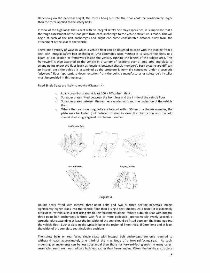
Diagram 5 shows typical methods of attaching safety belts.
Diagram 5
Where safety belts, other than looped belts, are anchored to the seat frame or the vehicle floor they
should be secured with mounting bolts in accordance with the following (Table 1):
Minimum Acceptable Size and Grade of Bolts for Safety belt Anchorages
Type of Anchorage Minibus Coach or Large Bus
Single Anchorage M10 Standard Material
M8 High Tensile Steel
M10 Standard Material
M8 High Tensile Steel
Double Anchorage M12 Standard Material
M10 High Tensile Steel
M12 Standard Material
M10 High Tensile Steel
Table 1
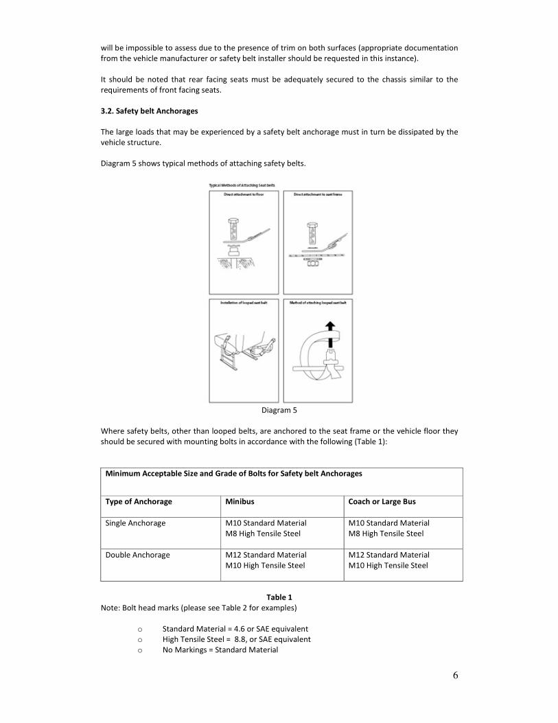
Note: Bolt head marks (please see Table 2 for examples)
o Standard Material = 4.6 or SAE equivalent
o High Tensile Steel = 8.8, or SAE equivalent
o No Markings = Standard Material
7
Table 2
If the examiner cannot determine the grade of bolt it must be assumed to be of Standard Grade.
It is essential that the appropriate sized bolt and bolt holes are used for the safety belt anchorage (i.e.
an 8mm bolt should not be used in an 11.5mm diameter hole). The only exception to this is where a
“stepped washer” or collar is used to eliminate the excessive clearance and a suitable washer is fitted
between the bolt head and the anchorage to prevent the bolt pulling through. The use of smaller
bolts, self tapping screws or wood screws is not acceptable.
It is not acceptable to drill tubular seat frames to allow belts to be bolted to the frame except in cases
where a manufacturer has approved the installation and the bus owner presents
documentation/certification issued by the manufacturer or his agent declaring that such an
installation is satisfactory.
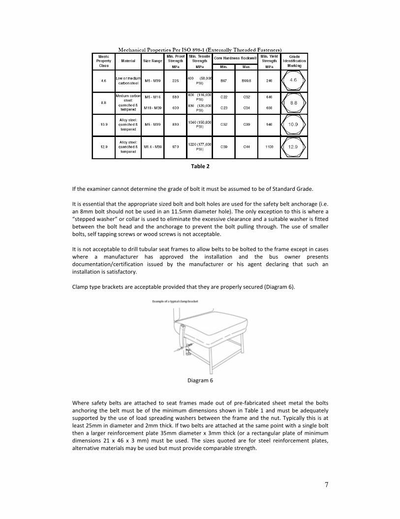
Clamp type brackets are acceptable provided that they are properly secured (Diagram 6).
Diagram 6
Where safety belts are attached to seat frames made out of pre-fabricated sheet metal the bolts
anchoring the belt must be of the minimum dimensions shown in Table 1 and must be adequately
supported by the use of load spreading washers between the frame and the nut. Typically this is at
least 25mm in diameter and 2mm thick. If two belts are attached at the same point with a single bolt
then a larger reinforcement plate 35mm diameter x 3mm thick (or a rectangular plate of minimum
dimensions 21 x 46 x 3 mm) must be used. The sizes quoted are for steel reinforcement plates,
alternative materials may be used but must provide comparable strength.
8
Where safety belts anchorages are attached directly to a metal floor a load spreading washer must be
used between the nut and the floor. The bolts must be at least the sizes specified in Table 1. Typically
this load spreading washer is at least 25 mm in diameter and 2 mm thick. If two belts are attached at
the same point with a single bolt then a larger reinforcement plate of minimum dimensions 35mm
diameter x 3mm thick (or a rectangular plate of minimum dimensions 21 x 46 x 3 mm) must be used.
The sizes quoted are for a steel reinforcement plates, alternative materials may be used but must
provide comparable strength. Reinforcement plates should follow, as far as practicable, any contours
in the floor to which they are attached.
Where safety belt anchorages are attached directly to a floor made of a material other than metal, or
where safety belts are fitted to the rear seats of a bus, check the anchorage to ensure that it is not
anchored solely to the floor or the material which separates the boot area from the passenger
compartment (plywood or thin metal sheet).
Safety belt anchorages in both these cases must be secured to a strong cross member connected to
the structural members of the vehicle. This connection should be to such a standard that there is
confidence that it will be able to transfer the safety belt loads into the structure of the vehicle.
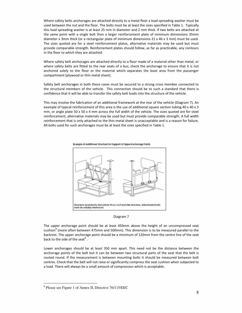
This may involve the fabrication of an additional framework at the rear of the vehicle (Diagram 7). An
example of typical reinforcement of this area is the use of additional square section tubing 40 x 40 x 3
mm, or angle plate 50 x 50 x 4 mm across the full width of the vehicle. The sizes quoted are for steel
reinforcement, alternative materials may be used but must provide comparable strength. A full width
reinforcement that is only attached to the thin metal sheet is unacceptable and is a reason for failure.
All bolts used for such anchorages must be at least the sizes specified in Table 1.
Diagram 7
The upper anchorage point should be at least 450mm above the height of an uncompressed seat
cushion8 (more often between 475mm and 500mm). This dimension is to be measured parallel to the
backrest. The upper anchorage point should be a minimum of 120mm from the centre line of the seat
back to the side of the seat8 .
Lower anchorages should be at least 350 mm apart. This need not be the distance between the
anchorage points of the belt but it can be between two structural parts of the seat that the belt is
routed round. If the measurement is between mounting bolts it should be measured between bolt
centres. Check that the belt will not raise or significantly compress the seat cushion when subjected to
a load. There will always be a small amount of compression which is acceptable.
8 Please see Figure 1 of Annex II, Directive 76/115/EEC
9
4. Safety belts and Restraint Systems
Safety belt and restraints should be “e” / “E” marked9.
Check that each safety belt is secured:
o to the vehicle structure, or where the belt is integral with the seat, to the seat structure
o using a fixing of adequate strength
o such that it can be separated from the anchorage without causing damage to the anchorage.
Check each belt for damage. Check the lock mechanism releases as required. Safety belt components
should not be fitted to seats in such a way that they significantly intrude into the gangway space and
are likely to cause injury to passengers either by tripping or by hitting the component.
Examine the condition of the attachment fittings and adjusting fitting on each belt. For seats with
integral safety belts, it might not be possible to examine the fixing of the safety belt to the seat.
Check each belt operates correctly by fastening each belt locking mechanism (buckle) and trying to
pull the locked sections apart. On retracting safety belts, check that, with the mechanism fastened
and the seat unoccupied, excess webbing is wound into the retractor unit. Where a lap/diagonal
retracting belt is fitted, check the position and operation of the retractor mechanism. A retractor
mechanism must be correctly positioned to ensure the correct operation of the belt. Non-retracting
safety belts should not be an obstruction or hazard when not in use (if possible they should be stored
or clipped out of the way).
Check that whilst sitting in each seat in turn, and wearing the safety belt, secured and correctly
adjusted, that the position of the webbing on the torso and the location of the effective belt
anchorage points in relation to the seated body position are correct. A lap belt or the lap section of a
3 point belt must be positioned to lie across the wearer’s pelvis and not the stomach. This is to reduce
the risk of abdominal injury and to prevent “submarining”. In practice this may result in the belt lying
across the top quarter of the thigh.
Submarining is when the hips of an occupant wearing a poorly fitting or loose safety belt slide under
the lap part of the belt. If this happens the lap part of the safety belt will apply crash forces to the
soft abdominal area between the pelvis and ribs.
Check the vehicle structure, fitments and components near each belt for sharp edges likely to cause
abrasion or damage to the belt during normal use.
Examine flexible buckle stalks for:
o Signs of corrosion or weakness. Pull the sheaths aside, if this can be done without damage.
o ‘Waggle’ flexible buckle stalks and listen for a clicking noise indicating broken strands of
cable.
Examine the condition of all safety belt webbing for cleanliness, cuts or obvious signs of deterioration.
Pay particular attention to webbing around anchorages, buckles and loops.
Subsequent cutting or reworking of the webbing will be a reason for failure. It is acceptable for the
free end of looped belts or static belts to be reworked to the extent of folding and stitching the
webbing so that it cannot pass back through the buckle to prevent the buckle from being dismantled.
Any knots in the belt webbing are unacceptable.
A “looped” type safety belt fitting (See Diagram 5) is acceptable provided its anchorage point it is not
free to move or “float” along any part of the seat structure. Any free movement in excess of 25mm is
a reason for failure.
9 Directive 77/541/EEC on the approximation of the laws of the Member States relating to safety belts
and restraint systems of motor vehicles/UNECE Regulation 16-04.
10
4.1. Important Point to Note
If lap belts are fitted and there is the possibility of passengers hitting their heads on any harsh object
such as a grab rail or seat stanchion, padding or other suitable protection must be provided on these
objects10
. The protection does not need to cover the full length of a seat grab rail but should cover a
length of at least 300mm directly in front of each passenger. Padding must be compressible and of a
depth of at least 50 mm, measured to the surface of the bar and not compress more than 25mm
under reasonable thumb pressure, or is 25mm thick and not compress more than 5mm. Ordinary seat
foam or pipe lagging foam is unlikely to be of sufficient density for this purpose.
10
As per the requirements of Appendix 6 of Annex III of Directive 74/408/EEC

11
5. Check List
Check List
Vehicle Owner details:
Address:
Vehicle identification: (VIN, Reg No. etc)
VIN No. REGISTRATION No.
Vehicle manufacturer/convertor details:
Record and Attach evidence of compliance with Appropriate Standards/Engineers Reports/Letters
from Vehicle Manufacturer or Vehicle Convertor
Inspection carried out by: Date:
Number of forward facing seating positions:
Number of rear facing seating positions:
Number of side facing seating positions:
Number of locations for a wheelchair:
1. Safety belt (including wheelchair occupant restraints):
• Are all seats fitted with a safety belt Yes no
• Are all safety belts either diagonal fixed at 3 points or lap belts Yes No
• Are all safety belts ‘e’ or ‘E’ marked
2. Anchorages (including wheelchair restraints/anchorages):
• Is the vehicle structure free from corrosion, serious deterioration or
fractures within 300mm (12”) of the anchorage
• Note: Where a safety belt is attached to a seat frame this will apply to all
seat mounting points
Yes No
• Are all safety belts securely fixed to the seat or to the vehicle structure Yes No
3. Locking Mechanism, Stalks, Retracting Mechanism and Fittings:
• Do all locking mechanisms lock and release as intended Yes No
• Are all attachment and adjustment fittings free from defects and are they
operating correctly
Yes No
• Are all flexible stalks in sound condition. (A clicking noise when waggling
the stalk indicates broken strands)
Yes No
• Do all retracting mechanism retract the webbing sufficiently to remove all
of the slack from the belt with the locking mechanism fastened and the
seat unoccupied
Yes No
4. Condition of Webbing:
• Is all webbing original not having been and/or reworked. (e.g. belts
knotted, fraying or fluffing removed by burning etc.)
Yes No
• Is the webbing free from fluffing or fraying which may obstruct correct
operation of the belt or which has clearly weakened the webbing
Yes No
• Is all stitching in good condition, complete, free from repairs and not frayed Yes No
• Is all webbing clean so that it is unlikely to soil passengers’ clothing Yes No
5. Safety belt Fittings:
• Are all guides, stalks or pivots free from obvious signs of structural
weakness such that failure is likely
Yes No
6. Seat or seats to which safety belts are attached:
• Are all seats securely fastened to the chassis or sub-frame Yes No
• Are all set legs and frames free from cracks or fractures Yes No

12
7. Installation:
• Are all parts of the installation free from sharp edges which could or is
likely to cut or abrade the webbing
Yes No
• Are all directly attached anchorages secured by standard safety belt mounting
bolts and washers
Yes No
• Are all directly attached anchorages attached to a load bearing member or do
they have suitable reinforcement
Yes No
• Do all anchorages attached to the floor have reinforcement plates of a suitable
size and contour
Yes No
• Where belts have been retrofitted to seats with tubular frame legs or tubular
“H” pattern legs, the seat frames been reinforced with buttressing and diagonal
bracing, or buttressing where a floor mounted belt is fitted close to a seat leg
Yes No
• Where tubular seat frames are fitted, they have not been drilled for the
purpose of attaching a safety belt
Yes No
• Is suitable padding provided in reference zones Yes No
• Are all lower anchorages more than 350 mm apart Yes No
• Are all lower anchorages positioned so that the occupant is restricted from
effectively moving forward. (the belt should lie across the stomach or forward
of the top quarter of the thigh)
Yes No
• Are all upper anchorage of three point belt greater than 475 mm above
uncompressed seat cushion measured parallel to the seat back
Yes No
• Are all upper anchorages of three point belt(s) more than 110 mm from centre
line of seat
Yes No
• For claw type seat mountings is there adequate means of securing the claws Yes No
• On seats fitted to a flat rail does the bolt pass through the leg, rail, floor and a
suitable reinforced structural member or the floor
Yes No
• Is all tracking for securing seats and wheelchairs securely attached to the
chassis or structural members
Yes No
• For any looped belts fitted is the free movement at the anchorage less than
25mm
Yes No
• Are the gangways free from any obstructions caused by the safety belt
components that are likely to cause injury to a passenger
Yes No
Overall assessment of Vehicles Safety Belt Installation
Acceptable ���� Unacceptable ���� (please tick as appropriate)
Signed: Date:
Note: Please indicate that items 1 through 7 have been inspected.
If indicating No for any sub-item(s) 1 through 7 please give further details/reasons below:
13
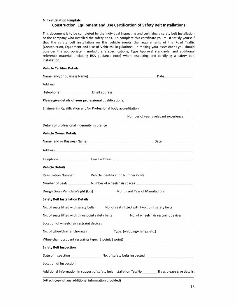
6. Certification template
Construction, Equipment and Use Certification of Safety Belt Installations
This document is to be completed by the individual inspecting and certifying a safety belt installation
or the company who installed the safety belts. To complete this certificate you must satisfy yourself
that the safety belt installation on this vehicle meets the requirements of the Road Traffic
(Construction, Equipment and Use of Vehicles) Regulations. In making your assessment you should
consider the appropriate manufacturer’s specifications, Type Approval standards, and additional
reference material (including RSA guidance note) when inspecting and certifying a safety belt
installation.
Vehicle Certifier Details
Name (and/or Business Name) _____________________________________ Date________________
Address____________________________________________________________________________
Telephone _________________ Email address: ___________________________________________
Please give details of your professional qualifications:
Engineering Qualification and/or Professional body accreditation __________________________
______________________________________________ Number of year’s relevant experience _____
Details of professional indemnity insurance ______________________________________________
Vehicle Owner Details
Name (and or Business Name) ____________________________________ Date _________________
Address____________________________________________________________________________
Telephone _________________ Email address: ___________________________________________
Vehicle Details
Registration Number_________ Vehicle Identification Number (VIN) ___________________________
Number of Seats ____________ Number of wheelchair spaces _______________________________
Design Gross Vehicle Weight (kgs) ____________ Month and Year of Manufacture ________________
Safety Belt Installation Details
No. of seats fitted with safety belts _____ No. of seats fitted with two point safety belts __________
No. of seats fitted with three point safety belts _________ No. of wheelchair restraint devices _____
Location of wheelchair restraint devices _________________________________________________
No. of wheelchair anchorages ______________ Type: (webbing/clamps etc.) ___________________
Wheelchair occupant restraints type: (2 point/3 point) ______________________________________
Safety Belt Inspection
Date of Inspection _________________ No. of safety belts inspected __________________________
Location of Inspection ________________________________________________________________
Additional Information in support of safety belt installation Yes/No ________ If yes please give details:
___________________________________________________________________________________
(Attach copy of any additional information provided)

14
Requirements for Certification
By certifying a safety belt installation you are declaring that each safety belt in the above vehicle
satisfies the following requirements of Road Traffic (Construction, Equipment and Use of Vehicles)
Regulations, (Statutory Instrument No. 190 of 196311
) in respect of safety belts and their installation:
For all buses:
34. (1) Every vehicle and trailer, and all parts and equipment for every vehicle and trailer, shall be
maintained in good and efficient working order, and shall be such and so maintained that no danger is
liable to be caused thereby.
96. (1) Every vehicle while used in a public place shall be such, and so maintained and used, that no
danger is likely to be caused to any person.
67. (1) Every vehicle (including all bodywork, upholstery and fittings) shall be properly constructed of
suitable materials and shall be of such a design that it is capable of withstanding the loads and
stresses likely to be met with in operation and is otherwise suitable for use for the carriage of
passengers.
Declaration
I hereby declare that the above information to be true and correct and that I am in possession of the
professional requirements set out in Note 1 below.
Signature of Certifier _______________________________________________ Date ______________
Note 1 :
This certification must be completed by the authorised representative of an Approved Test Centre
(ATC) or by a competent person who meets the following minimum requirements:
• an Engineering/Technical Qualification (Level 7 or higher accredited courses12
) or appropriate
accreditation with Engineers Ireland13
or the Institute of Automobile Engineer Assessors14
• a minimum of 5 years experience of working in a suitable technical environment (preferably
Automotive or Engineering Environment)
• access to adequate facilities to carry out a thorough vehicle examination, and
• appropriate professional indemnity insurance.
Or
• be an authorised representative15
of a company or vehicle manufacturer engaged in the
installation of safety belts to Type Approval standards.
11
S.I. No. 190 of 1963 12
See Engineers Ireland, Accredited Courses. 13
Chartered or Associate Engineer. 14 Member or Incorporated Member. 15
Such as a Director under the Companies Act, 1963 (as amended)).