RS ENE 428 Microwave Engineering Lecture 3 Polarization, Reflection and Transmission at normal...
38
RS RS ENE 428 Microwave Engineering Lecture 3 Polarization, Reflection and Transmission at normal incidence 1
-
Upload
whitney-morton -
Category
Documents
-
view
221 -
download
2
Transcript of RS ENE 428 Microwave Engineering Lecture 3 Polarization, Reflection and Transmission at normal...
RSRS
ENE 428Microwave
Engineering
Lecture 3 Polarization, Reflection and Transmission at normal incidence
1

RS
Uniform plane wave (UPW) power transmission
2
201Re
2jzx
zEe e a
from1
Re( )2
avgP E H
������������������������������������������
2
201cos
2zx
zEe a
W/m2
2
RS3
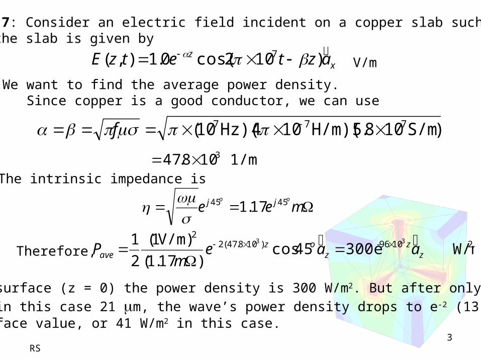
Example 6.7: Consider an electric field incident on a copper slab such that the field in the slab is given by
xz aztetzE
)102cos(0.1),( 7
V/m
We want to find the average power density.Since copper is a good conductor, we can use
)S/m108.5)(H/m104)(Hz10( 777 f
1/m 108.47 3The intrinsic impedance is
meeoo jj 4545 17.1
Therefore, 21096-)108.47(2
2
W/m300e45cos)17.1(
)V/m1(
2
1 33
zz
zoz
ave aaem
P
At the surface (z = 0) the power density is 300 W/m2. But after only 1 skin
depth, in this case 21 m, the wave’s power density drops to e-2 (13.5%) of its surface value, or 41 W/m2 in this case.

RS
Polarization• UPW is characterized by its propagation direction
and frequency.
• Its attenuation and phase are determined by medium’s parameters.
• Polarization determines the orientation of the electric field in a fixed spatial plane orthogonal to the direction of the propagation.
• Specifying only the electric field direction is sufficient since magnetic field is readily found from using Maxwell’s equation
4
E

RS
Linear polarization
• Consider in free space,
0( , ) cos( ) xE z t E t z a
��������������E��������������
• At plane z = 0, a tip of field traces straight line segment called “linearly polarized wave”
E��������������
5

RS
• A pair of linearly polarized wave also produces linear polarization
Linear polarization
0 0( , ) cos( ) cos( )x yx yE z t E t z a E t z a
��������������
At z = 0 plane
At t = 0, both linearly polarized waveshave their maximum values.
0 0(0,0) x yx xE E a E a
��������������
(0, ) 04
�������������� TE
0 0(0, ) cos( ) cos( )x yx yE t E t a E t a
��������������
6

RS7
Linear polarization• The tilt angle (tau) is the angle the line makes
with the x-axis
• The axial ratio is the ratio of the long axis of an ellipse to the short axis
RS
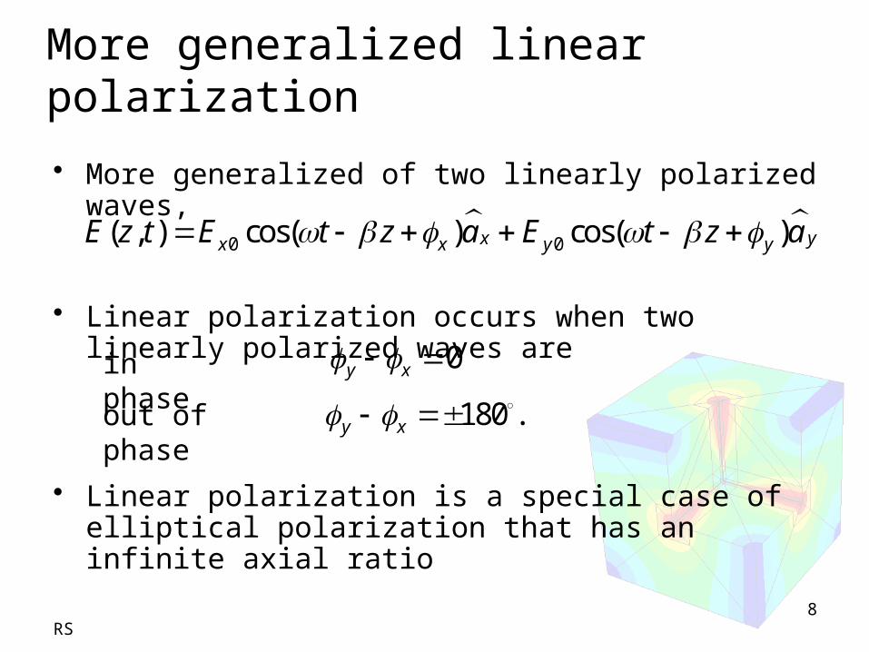
• More generalized of two linearly polarized waves,
• Linear polarization occurs when two linearly polarized waves are
• Linear polarization is a special case of elliptical polarization that has an infinite axial ratio
More generalized linear polarization
0 0( , ) cos( ) cos( )x yx x y yE z t E t z a E t z a
��������������
in phase 0y x
out of phase 180 . y x
8

RS
• Superposition of two linearly polarized waves that
• If x = 0 and y = 45, we have
Elliptically polarized wave
0 180y x or
0 0(0, ) cos( ) cos( )
4x yx yE t E t a E t a
��������������
9

RS
• occurs when Exo and Eyo are equal and
• Right hand circularly polarized (RHCP) wave
• Left hand circularly polarized (LHCP) wave
• Left and right are referred to as the handedness of wave polarization
Circularly polarized wave
90y x
0 0(0, ) cos( ) cos( )
2x yx yE t E t a E t a
��������������
0 0(0, ) cos( ) cos( )
2x yx yE t E t a E t a
��������������
90y x
90y x
10

RS
• Phasor forms:
for RHCP,
for LHCP,
Circularly polarized wave
0 0( 0) yx
jjx yx yE z E e a E e a
��������������from
0( 0) ( )x yxE z E a ja
��������������
0( 0) ( )x yxE z E a ja
��������������
Note: There are also RHEP and LHEP 11

RS
Ex1 Given
,determine the polarization of this wave
( , ) 8cos( 30 ) 8cos( 90 ) ��������������
x yE z t t z a t z a
12

RS
Ex2 The electric field of a uniform plane wave in free space is given by , determine
50100( ) j ys z xE a ja e
��������������
a) f
b) The magnetic field intensity sH��������������
13

RS
c)
d) Describe the polarization of the wave
S��������������
14

RS
Reflection and transmission of UPW at normal incidence
15

RS
Assume the medium is lossless, let the incident electric field to be
or in a phasor form
since
then we can show that
1 10( , ) cos( ) xxE z t E t z a
��������������
• Normal incidence – the propagation direction is normal to the boundary
Incident wave
11
1
EH a
����������������������������
11 10( ) j z
xxE z E e a ��������������
1101
1
( ) j zxy
EH z e a
��������������
16

• Transmitted wave
RS
Assume the medium is lossless, let the transmitted electric field to be
then we can show that
22 20( ) j z
xxE z E e a ��������������
Transmitted wave
2202
2
( )
��������������j zx
yE
H z e a
17

RS
At z = 0, we have
and
1 = 2 are media the same?
tan1 tan 2
tan1 tan 2
E E
H H
• From boundary conditions,
Reflected wave (1)
10 20x xE E
10 20
1 2
x xE E
18

• There must be a reflected wave
RS
and
This wave travels in –z direction.
Reflected wave (2)
11 10( ) j z
xxE z E e a ��������������
1101
1
( ) j zxy
EH z e a
��������������
19

• Boundary conditions (reflected wave is included)
RS
from
therefore at z = 0
(1)
Reflection and transmission coefficients (1)
1 2x xE E
1 1 2x x xE E E
10 10 20x x xE E E
20
RS
from
therefore at z = 0
(2)
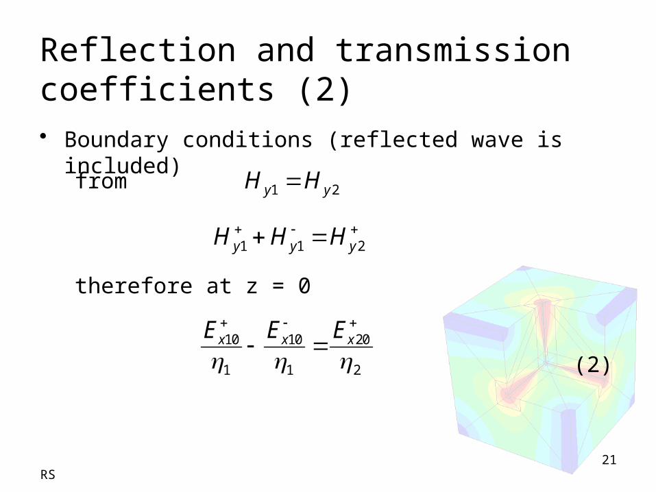
• Boundary conditions (reflected wave is included)
Reflection and transmission coefficients (2)
1 2y yH H
1 1 2y y yH H H
10 10 20
1 1 2
x x xE E E
21
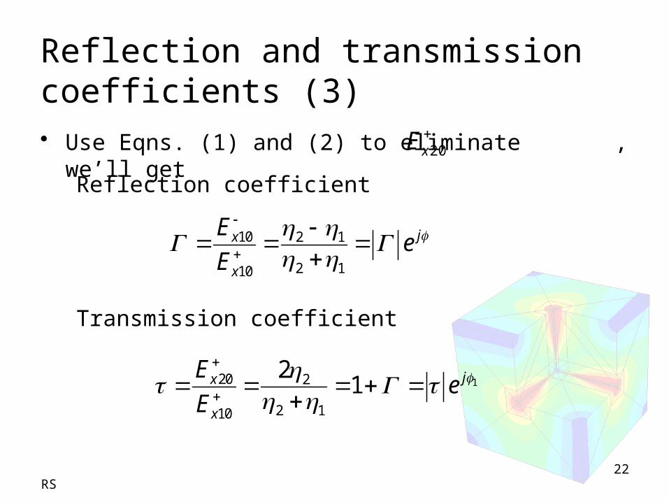
• Use Eqns. (1) and (2) to eliminate , we’ll get
RS
Reflection coefficient
Transmission coefficient
Reflection and transmission coefficients (3)
10 2 1
2 110
jx
x
Ee
E
120 2
2 110
21 jx
x
Ee
E
22
20xE

RS
Types of boundaries: perfect dielectric and perfect conductor (1)
From
.
Since 2 = 0 then = -1 and Ex10+= -Ex10
-
1 1 1x x xE E E
1 11 10 10
j z j zx x xE E e E e
22
2 2
0jj
20 0xE
23

RS
Types of boundaries: perfect dielectric and perfect conductor (2)
This can be shown in an instantaneous form as
10 1( , ) 2 sin( )sinx xE z t E z t
10 12 sin( )xj E z
Standing wave
24
101 )( 11x
zjzjx EeeE

RS
Standing waves (1)
When t = m, Ex1 is 0 at all positions.and when z = m, Ex1 is 0 at all time.
Null positions occur at
1
2z m
1
2m
z
25

RS
Standing waves (2)
Since
and ,
the magnetic field is
or .
Hy1 is maximum when Ex1 = 0
So, E and H are said to be 90o out of phase. There will be no power transmission on either side of the media
Poynting vector
1 1x yE H
1 1x yE H
1 1101
1
( )j z j zxy
EH e e
101 1
1
2( , ) cos cosx
y
EH z t z t
S E H ������������������������������������������ 26
2201
cos2
zxz
Ee a
RS
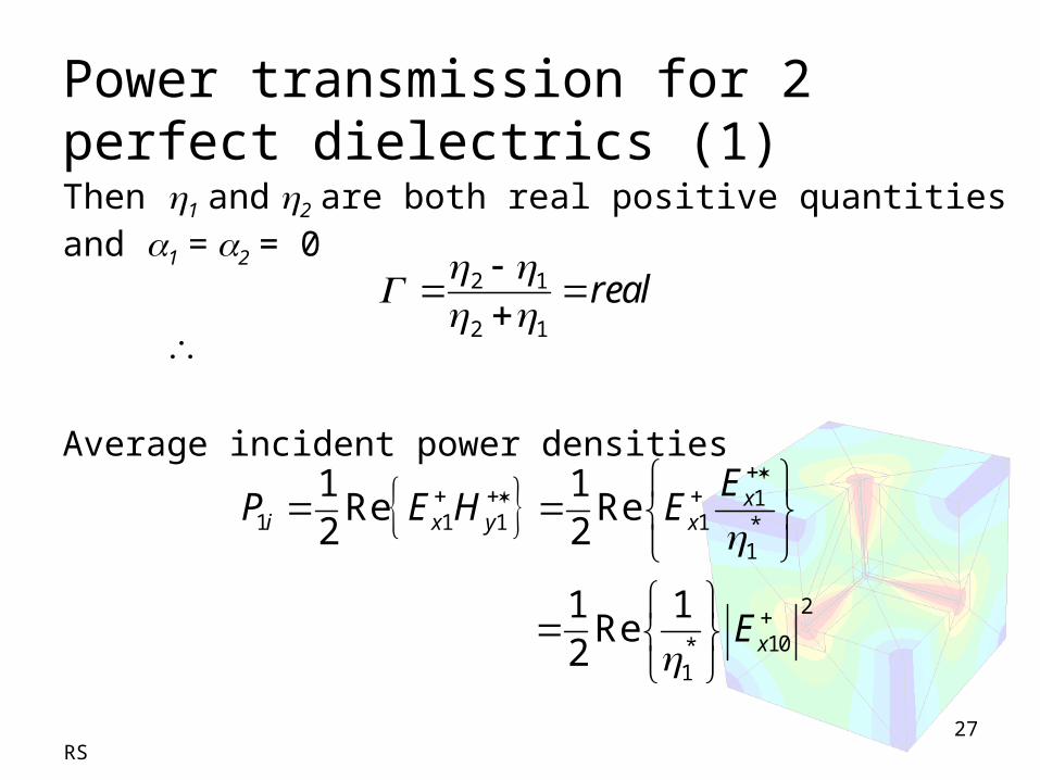
Power transmission for 2 perfect dielectrics (1)Then 1 and 2 are both real positive quantities and 1 = 2 = 0
Average incident power densities
11 1 1 1 *
1
1 1Re Re
2 2
xi x y x
EP E H E
2 1
2 1
real
2
10*1
1 1Re
2 xE
27

RS
Ex3 Let medium 1 have 1 = 100 and medium 2 have 2 = 300 , given Ex10
+ = 100 V/m. Calculate average incident, reflected, and transmitted power densities
28
RS
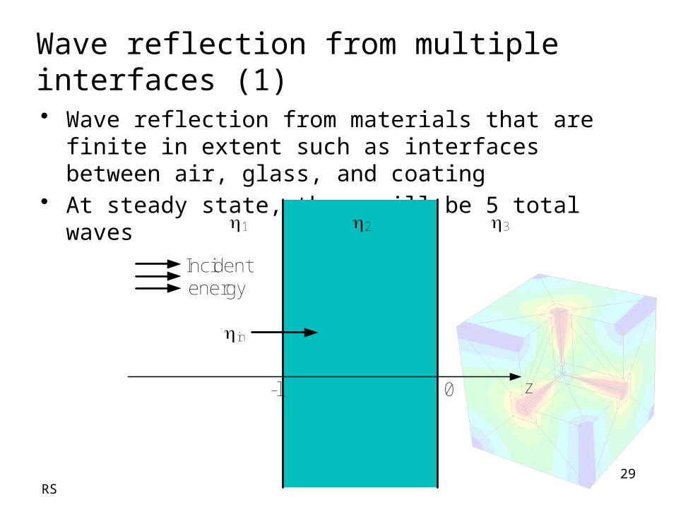
Wave reflection from multiple interfaces (1)• Wave reflection from materials that are finite in
extent such as interfaces between air, glass, and coating
• At steady state, there will be 5 total waves
Incident energy
in
1 2 3
-l 0 z
29
RS
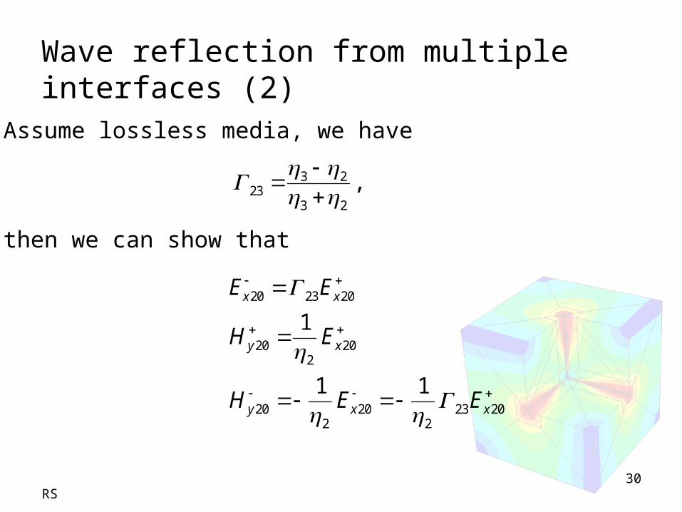
Wave reflection from multiple interfaces (2)Assume lossless media, we have
then we can show that
3 223
3 2
,
20 23 20
20 202
20 20 23 202 2
1
1 1
x x
y x
y x x
E E
H E
H E E
30
RS
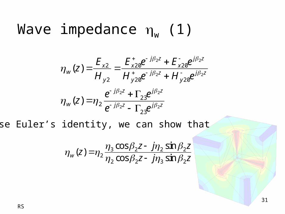
Wave impedance w (1)
Use Euler’s identity, we can show that
3 2 2 22
2 2 3 2
cos sin( )
cos sinw
z j zz
z j z
31
zjzj
zjzj
w
zjy
zjy
zjx
zjx
y
xw
ee
eez
eHeH
eEeE
H
Ez
22
22
22
22
23
232
2020
2020
2
2
)(
)(

RS
Wave impedance w (2)Since from B.C.
at z = -l
we may write
1 1 2x x xE E E
1 1 2y y yH H H
10 10 2x x xE E E
32
)( lz
)( lz )( lz
(1a)
(2a)
Using eqns (1a) and (2a) to eliminate , we’ll get … 2xE
w
xxx EEE
2
1
10
1
10

RS
Input impedance insolve to get
10 1
110
x in
inx
E
E
3 2 2 22
2 2 3 2
cos sincos sinin
l j ll j l
33
)( lzw

RS34
Power Transmission and Reflection
Incident energy
in
1 2 3
-l 0 z
2
1
12
in
in
in
r
P
P
22
1
1211
in
in
in
t
P
P
The power in region 2 stays constant in steady-state; power leaves that region to form the reflected and transmitted waves, but is Immediately replenished by the incident wave (from region 1)
If = 0, then there’ll be total transmission.And = 0 when in = 1 , or the input impedance is matched to that of the incident medium. So how do we achieve this?
Pin
Pr
Pt

RS35
Half-wave matching method
Suppose 13 ml 2
ml 2
2
22ml
and
Therefore, and so
Hence, the 2nd region thickness is the multiple “half-wavelength” as measured in that medium
Using eqn: 3 2 2 22
2 2 3 2
cos sincos sinin
l j ll j l
We’ll get 3 in when 2
2ml
The general effect of a multiple half-wave is to render the 2nd region immaterial to the results on reflection and transmission. Equivalently we
have a single interface problem involving 1 and 3

RS36

RS
Refractive index
rn
Under lossless conditions,
0 0 r
nc
0 0
0
1
rn
p
cv
n
0pv
f n
37

RS38
Homework
6.32: Given yo
x aztazttzE
)45sin(20)cos(10),( V/m, find the polarization and handedness.
6.38: Suppose medium 1 (z < 0) is air and medium 2 (z > 0) has r = 16. The trans-
mitted magnetic field intensity is known to be Ht = 12cos(t – β2z)ay mA/m.(a) Determine the instantaneous value of the incident electric field. (b) Find the reflected time-averaged power density
6.48: A 100-MHz TE polarized wave with amplitude 1.0 V/m is obliquely incidentfrom air (z < 0) onto a slab of lossless, nonmagnetic material with r = 25 (z > 0).
The angle of incidence is 40o. Calculate (a) the angle of transmission, (b) the reflection and transmission coefficients, and (c) the incident, reflected and transmitted fields.