RS-485 Keypad - KEYLESS
52
Essex Electronics, Inc. | 805.684.7601 | 800.KEY-LESS | fax 805.684.0232 | keyless.com INSTALLATION & INSTRUCTION MANUAL RS-485 Keypad
Transcript of RS-485 Keypad - KEYLESS

Essex Electronics, Inc. | 805.684.7601 | 800.KEY-LESS | fax 805.684.0232 | keyless.com
INSTALLATION & INSTRUCTION MANUAL
RS-485Keypad

Essex Electronics, Inc. | 805.684.7601 | 800.KEY-LESS | fax 805.684.0232 | keyless.comi
All rights reserved. No part of this documentation may be reproduced in any form, without prior written consent of Essex Electronics, Inc. Essex Electronics shall not be liable for errors contained in this manual. The information in this document is subject to change without notice. Essex Electronics, Inc. reserves the right to modify this documentation and to make improvements or changes to the product(s) contained in this documentation at any time.
Document Information Installation/Operation Manual for KTP-485 Keypads - June 2018. This documentation is also applicable to prior revisions except where noted.
Trademarks Keyless Entry® is a registered trademark of Essex Electronics, Inc.
Contact Information Essex Electronics, Incorporated 1130 Mark Avenue, Carpinteria, CA 93013 (805) 684-7601 or (800) 539-5377 (KEY-LESS) FAX (805) 684-0232
Website: keyless.com General email: [email protected] Technical Support email: [email protected]
Copyright© 2015 Essex Electronics, Inc. All rights reserved.
Heavy Duty RS-485 Keypad
Essex Electronics, Inc. | 805.684.7601 | 800.KEY-LESS | fax 805.684.0232 | keyless.com ii
Table of Contents
Introduction ....................................................................................1Overview - Heavy Duty RS-485 Keypad ........................................1Keypad............................................................................................2Keypad Specifications .....................................................................2Keypad Part Numbers .....................................................................2Keypad Cutting Templates ...............................................................3Keypad Connector Diagram .........................................................4Keypad............................................................................................6Configuring The Keypad ..................................................................6Configuring The Device Address .....................................................7Configuring The Baud Rate / Parity .................................................8Configuring The RS-485 Turnaround Delay ....................................9Configuring The Power Up Indicator/Output Settings ......................9Configuring The Event Mode Settings ........................................... 11Keypad RS-485 Data Packet Formats ........................................12Packet Wrapper .............................................................................12Commanding The Data Field .........................................................14Response Data Field .....................................................................15Event-Generated Data Field ..........................................................17Keypad Commands and Responses .........................................19Reset Keypad Command - [00] .....................................................19Read Keypad Firmware Version - [01]...........................................19Set Listen Only Mode - [02] ...........................................................20
continued next page

Essex Electronics, Inc. | 805.684.7601 | 800.KEY-LESS | fax 805.684.0232 | keyless.comiii
Read Keypad Counters - [03] ........................................................21Reset Keypad Counters - [04] .......................................................22Read Flash Power-Up Indicator/Output Settings - [05] .................23Set Flash Power-Up Indicator/Output Settings - [06].....................24Disable Keypad Input- [10] ............................................................25Enable Keypad Input - [11] ............................................................25Tamper Alarm For 15 Seconds - [12] .............................................26Tamper Alarm For 30 Seconds - [13] .............................................26Tamper Alarm For 60 Seconds - [14] .............................................27Stop Tamper Alarm Immediately- [15] ...........................................27Read Keypad Input Data - [20] ......................................................28Read Input Status - [21].................................................................29Read Keypad Input Data & Input Status - [22] ..............................30Read Current Indicator/Outputs States - [27] ................................31Set Indicator/Outputs States - [3X] ................................................32How The LRCC Values Are Calculated .........................................36Frequently Asked Questions..........................................................38Warranty & Repairs .....................................................................44
Table of Contents, cont’d.

1Essex Electronics, Inc. | 805.684.7601 | 800.KEY-LESS | fax 805.684.0232 | keyless.com
Introduction Overview - Heavy Duty RS-485 Keypad For Industrial Process Control EquipmentThe KTP Series 12-Pad features no moving parts, rugged stainless steel construction, and circuit assembly encapsulation to ensure performance in high use or harsh environments. Ideal for process control equipment and SCADA systems, the KTP-485 Keypad is designed to provide bi-directional serial communications protocol in Hexadecimal 7-bit ASCII data (half duplex). Configurable in the field, up to 128 keypads can be added on the RS-485 network with selectable parity and baud rates up to 115.2 kbps. Data can be transferred using either Polling Mode for complete master bus control, or Event Mode, which provides asynchronous data transfers on the bus. The RS-485 connection is slew rate limited and provided with +/- 15KV ESD protection. The RS-485 is available as a 3x4 or 2x6 Keypad. Custom graphics are available.
3x4 Keypad (left) and 2x6 Keypad (right)

Essex Electronics, Inc. | 805.684.7601 | 800.KEY-LESS | fax 805.684.0232 | keyless.com2
Input Voltage: 5VDC or 12 to 24VDC (Jumper Selectable)
Standby Current Draw: 25mAOutputs: 4 Open Collector, 1/4 A Max to
GroundKeypad Switch Life: >1 Billion CyclesKeypad Operating Environment: -40°C to +70°C (-40°F to +160°F),
100% Relative Humidity3x4 Keypad Dimensions: 5-1/8”H x 3-3/8”W x 7/16”D
(13 x 8.6 x 1.1 cm)2x6 Keypad Dimensions: 7-1/8”H x 1-3/4”W x 3/4”D
(13 x 8.6 x 1.1 cm)3x4 Keypad Weight: 16 oz (454 gm) 2x6 Keypad Weight: 4.4 oz (125 gm)LED’s: 1 Red, 1 Green
Keypad Keypad Specifications
Keypad Part Numbers
3x4 KeypadKTP-4853-SN Stainless Steel BezelKTP-4853-KN Black BezelKTP-4853-XX No Bezel
2x6 KeypadKTP-4852-LI IlluminatedKTP-4852-SN Stainless Steel Overlay

3Essex Electronics, Inc. | 805.684.7601 | 800.KEY-LESS | fax 805.684.0232 | keyless.com
Keypad Cutting Templates

Essex Electronics, Inc. | 805.684.7601 | 800.KEY-LESS | fax 805.684.0232 | keyless.com4
Keypad Connector DiagramCONFIGURATION PINS (Do NOT apply voltage)
VOLTAGE SELECT DC ONLY (Do NOT apply voltage)12 DC - Jumper on 1 pin only5V- Jumper on both pins
YELLOW- Input 1 (Do NOT apply voltage)
PINK- Input 2 (Do NOT apply voltage)
BLUE- CCTV
BROWN- RS485 bus T- (Do NOT apply voltage)
TAN- Earth Ground tie to facility metal
BLACK- Circuit ground, neg of power supplyORANGE- RS485 bus T+ (Do NOT apply voltage)
VIOLET- Output 3
RED- Input Voltage, pos of power supplyWHITE- Output 2
GREEN- Output 1
NOTE: The 2x6 connector is rotated 180 degreesCAUTION: Do NOT run this low voltage wiring in conduit with or adjacent to line voltage wiring.
continued next page
The GREEN, WHITE, VIOLET, and BLUE outputs are 1/4A open collector outputs that are user controlled, except the BLUE wire, which goes active low for 30 seconds wiht any key press.
The YELLOW and PINK wires are user inputs that detect when these lines are connected to ground.

5Essex Electronics, Inc. | 805.684.7601 | 800.KEY-LESS | fax 805.684.0232 | keyless.com
Internal Relay Wiring Diagram
The RS-485 bus may be terminated by a 120 ohm resistor by installing the termination jumper. On the 3x4 keypad, this is on the left side, centered. On the 2x6 keypad, this will need to be done external to the keypad using a radial 120 ohm resister (not supplied by Essex Electronics).

Essex Electronics, Inc. | 805.684.7601 | 800.KEY-LESS | fax 805.684.0232 | keyless.com6
Keypad Configuring The KeypadThe keypad’s Device Address and RS-485 Serial Communication settings are set using a special Configure Mode. To enter, Configure Mode power must first be removed from the keypad. After power is removed, jumper the configure pins together, and then apply power to the keypad. Leave the configure pins shorted until the keypad sounds 4 short beeps (about 4 seconds). At this time, the Red LED will be ON and the Green LED will be Flashing Fast to indicate Configure Mode is active. After configuration has been completed, normal operation is restored by removing power from the keypad, removing the configuration jumper, and then reapplying power.
Each item to be configured is done in the same way. First, the configuration item number digit is pressed. After this digit is entered, 3 short beeps will be output and the LED’s will change to Red Flashing Flash and Green On Solid. Next, the configuration values for that item are entered. After the values are entered, the keypad will output 4 short beeps to indicate the configuration item has been set. It should be noted that the number of digits for the item’s value varies with each item type. A long beep at any time means an invalid entry was made and the item needs to be reentered from the start.

7Essex Electronics, Inc. | 805.684.7601 | 800.KEY-LESS | fax 805.684.0232 | keyless.com
D D D = DEVICE ADDRESS 3-DIGIT DECIMAL (000-127) (FACTORY DEFAULT=001)
Configuring The Device AddressThe Device Address is the address value that the keypad may respond to. It may be set to a value of 000 to 127 (0x00 to 0x7F hex). To set the Device Address, enter the digit ‘1’. After the 3 beeps, enter 3 address digits (DDD) which is the DECIMAL Device Address for the keypad. These can be in the range of 000 to 127 (decimal) and is default to 001, for address 0x00 to 0x7F (hex). After the third digit is entered, the keypad will output 4 short beeps to indicate the address has been set.
Device Address:1 D D D
Essex Electronics, Inc. | 805.684.7601 | 800.KEY-LESS | fax 805.684.0232 | keyless.com8
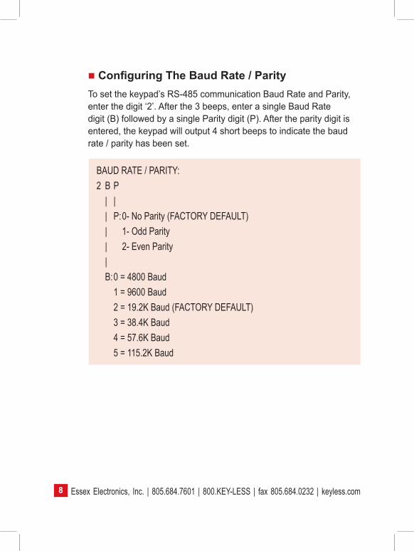
Configuring The Baud Rate / ParityTo set the keypad’s RS-485 communication Baud Rate and Parity, enter the digit ‘2’. After the 3 beeps, enter a single Baud Rate digit (B) followed by a single Parity digit (P). After the parity digit is entered, the keypad will output 4 short beeps to indicate the baud rate / parity has been set.
BAUD RATE / PARITY:2 B P | | | P: 0- No Parity (FACTORY DEFAULT) | 1- Odd Parity | 2- Even Parity | B: 0 = 4800 Baud 1 = 9600 Baud 2 = 19.2K Baud (FACTORY DEFAULT) 3 = 38.4K Baud 4 = 57.6K Baud 5 = 115.2K Baud

9Essex Electronics, Inc. | 805.684.7601 | 800.KEY-LESS | fax 805.684.0232 | keyless.com
Configuring The RS-485 Turnaround DelayThe Turnaround Delay is the time between when a command is received by the keypad and it begins to send its response. This allows time for the RS-485 bus to stabilize. This may be set to a delay of 0 to 4950 uSec in 50 uSec steps. To set the Turnaround Delay, enter the digit ‘3’. After the 3 beeps, enter a 2-digit value (TT) from 00 to 99 which sets the delay to the value entered multiplied by 50 uSecs. After the second value digit is entered, the keypad will output 4 short beeps to indicate the turnaround delay has been set.
Turnaround Delay Setting:3 T T T T = 2 Digit Turn Around Delay (00-99) Value Delay = Value * 50uSec (DEFAULT 00 = 0 uSec)
Configuring The Power Up Indicator/Output SettingsWhen the keypad powers up or is reset, the Indicator/Outputs will always be set to a predefined state. This state may be programmed in the Configure Mode. It can also be programmed or changed using RS-485 commands. To program the settings in configure mode, enter the digit ‘4’. After the 3 beeps, enter 5 digits (A1, A2, A3, RL, GL) which set each of the 5 indicator/outputs to their power up state setting. See the table on the next page. After the fifth digit is entered, the keypad will output 4 short beeps to indicate the power up settings have been set.

Essex Electronics, Inc. | 805.684.7601 | 800.KEY-LESS | fax 805.684.0232 | keyless.com10
Power Up Indicator/Output Settings:4 A1 A2 A3 RL GL | | | | | | | | | GL: 0 - Green Off (FACTORY DEFAULT) | | | | 1 - Green On | | | | 2 - Green Off + Flash On Beep | | | | 3 - Green On + Flash On Beep | | | | 4 - Green Follow Input 1 | | | | 5 - Green Follow Input 2 | | | | 6 - Green Follow Input 1 + Flash On Beep | | | | 7 - Green Follow Input 2 + Flash On Beep | | | | 8 - Green Slow Flash | | | | 9 - Green Fast Flash | | | | | | | RL: 0 - Red Off | | | 1 - Red On | | | 2 - Red Off + Flash On Beep | | | 3 - Red On + Flash On Beep (FACTORY DEFAULT) | | | 4 - Red Follow Input 1 | | | 5 - Red Follow Input 2 | | | 6 - Red Follow Input 1 + Flash On Beep | | | 7- Red Follow Input 2 + Flash On Beep | | | 8 - Red Slow Flash | | | 9 - Red Fast Flash | | | | | A3: 0 - OUT 3 Off (FACTORY DEFAULT) | | 1 - OUT 3 On | | | A2: 0 - OUT 2 Off (FACTORY DEFAULT) | 1 - OUT 2 On | A1: 0 - OUT 1 Off (FACTORY DEFAULT) 1- OUT 1 On

11Essex Electronics, Inc. | 805.684.7601 | 800.KEY-LESS | fax 805.684.0232 | keyless.com
Configuring The Event Mode SettingsThe keypad will always send a response to a command. In addition, the keypad can be configured to send data asynchronously whenever keypad data has been entered or an input state changes. This is called “Event Mode.” The Event Mode may be programmed in the Configure Mode. It can also be programmed or changed using RS-485 commands. To program the Event Mode in configure mode, enter the digit ‘5’. After the 3 beeps, enter a single digit (EV) which sets the Event Mode of the keypad. After this digit is entered, the keypad will output 4 short beeps to indicate the Event Mode setting has been set.
EVENT OPERATION SETTINGS:5 EV | EV: 0 - No Events Sent (FACTORY DEFAULT) 1 - Send Key Entry Events Only 2 - Send Input Change Events Only 3 - Send Input and Key Events

Essex Electronics, Inc. | 805.684.7601 | 800.KEY-LESS | fax 805.684.0232 | keyless.com12
Keypad RS-485 Data Packet Formats Packet WrapperData transfer to and from the keypad is accomplished using an 18 ASCII character set. These characters are the start character – colon [:], the end character – asterisk [*], and the 16 characters representing a hexadecimal digit – [0-9,A-F].
All keypad information, both sent and received, is exchanged using a standard packet format. This packet is composed of a Header Field, a Data Field, and a Trailer Field.
The Header Field consists of 3 ASCII characters. The first start character is always an ASCII colon [:]. The next 2 characters are the 7 bit binary device address sent as 2 ASCII hex digits [00-7F].
The Data Field contains transaction information. This field would be a Command Data Field if the data is a command being sent to the keypad or a Response or Event Data Field if the data is a response or event being sent from the keypad.
The Trailer Field consists of three ASCII characters. The first 2 characters are an 8 bit binary Longitudinal Redundancy Check sent as 2 ASCII hex digits [00-FF]. This LRCC is calculated on all the data in the packet except the start character [:] and the end characters [*]. The last character in the trailer is always an ASCII asterisk [*]. See “LRCC” calculation description on page 36.
All the Data Field types (Command, Response and Event) are wrapped inside this packet format.

13Essex Electronics, Inc. | 805.684.7601 | 800.KEY-LESS | fax 805.684.0232 | keyless.com
RS-485 PACKET FORMAT HEADER DATA TRAILERSTART [:] DEV ADDR Data Field LRCC END [*]
HEADER START ASCII, Colon [:]DEV ADDR A 7-bit binary Device Address sent as a
2-digit ASCII hex value [00–7F]DATADATA FIELD A Field containing either a Command,
Response or Event Data Field.TRAILERLRCC 8-bit binary Longitudinal Redundancy Check
value sent as 2 ASCII hex characters [00-FF]. The LRCC Excludes the Start and End characters.
END ASCII Asterisk [*]

Essex Electronics, Inc. | 805.684.7601 | 800.KEY-LESS | fax 805.684.0232 | keyless.com14
Commanding The Data FieldThe Command Data Field consists of a Command Field and possibly a Data Field. The Command Field is a hex command value in the range of [00-6F] which is sent as 2 ASCII hex digits. The Data Field, if required, is comprised of ASCII hex character data [0-F] information. Most commands do not require a data field and are only the 2 ASCII hex command digits. Several commands require additional data and will have a Data Field. The length of the Data Field will depend on the command being sent. See Command Section.
COMMAND DATA FIELD FORMATCOMMAND DATA
COMMANDThe Command is the operation the keypad is to perform and is a value in the range of [00-6F] sent as 2 ASCII hex characters. These values are explained in the Command Section.DATA Most Commands do not require additional data and will not have a Data Field. A few commands require some additional data and that information is contained here. The length of the Data Field depends on the command being sent. This is explained in the Command Section.

15Essex Electronics, Inc. | 805.684.7601 | 800.KEY-LESS | fax 805.684.0232 | keyless.com
Response Data FieldWhen a command is sent to the keypad, the keypad will respond with a Response Packet. This response is a standard packet containing the following Data Field.
The first field is a Command+Error Field containing the 7 bit binary command value it is responding to sent as a 2-digit ASCII hex digits. If the command caused an error, the value of the command will have the high order bit (0x80) turned on. If the high order bit is on, the Data Field will indicate the type of error. The one exception to this is if the Command+Error value is between 70 and 7F hex. In this case, the packet is an Event Generated Field and not a response to a command. See Event Generated Data Field.
The Data Size Field contains an 8-bit binary byte count sent as 2 ACSII hex digits. This value is the number of Data Bytes to follow.
The Data Field contains the response data. This data is always sent as ASCII hex characters (0-F).

Essex Electronics, Inc. | 805.684.7601 | 800.KEY-LESS | fax 805.684.0232 | keyless.com16
RESPONSE DATA FIELD FORMATCOMMAND+ERROR DATA SIZE DATA
COMMAND+ERROR8 bit binary value sent as 2 ASCII hex characters [00-FF]. The 8 bit value is the command value sent by the master. The value will have hex 0x80 added to the command value if an Error occurred If the first character is an ASCII [7] the packet was generated from an event and not from a poll command. It must be treated as an Event Generated Data Field (see Event Generated Field).DATA SIZE8 bit binary value sent as 2 ASCII hex characters [00-FF] indicating the number of ASCII data characters to follow in the DATA FieldDATAASCII hex character data [0-F] information of the character length specified in DATA SIZE

17Essex Electronics, Inc. | 805.684.7601 | 800.KEY-LESS | fax 805.684.0232 | keyless.com
Event-Generated Data FieldIf the keypad has an Event-Generated mode enabled, it will send packets whenever events for which that mode are enabled occur. If Event Mode is Disabled, no Event-Generated packets will ever be sent. The Event-Generated data field is a standard packet containing the following Data Field.
The Event Field contains 2 ASCII digits. The first digit is always an ASCII [7] indicating this is an Event-Generated Field. The second digit is the type of event being reported. This will be an ASCII value of [0-1].
The Data Size Field contains an 8 bit binary byte count sent as 2 ACSII hex digits. This value is the number of Data Bytes to follow.
The Data Field contains the Event data. This data is always sent as ASCII hex characters [0-F]. This data can be either Keypad Data Entered or Input States depending on the Type digit.

Essex Electronics, Inc. | 805.684.7601 | 800.KEY-LESS | fax 805.684.0232 | keyless.com18
AN EVENT-GENERATED DATA FIELD EVENT DATA SIZE DATA ASCII [7] TYPE
EVENT An Event-Generated Field. The first character will always be an ASCII [7] followed by a TYPE:
TYPE Type Of Event – ASCII [0-1]TYPE = 0 Keypad Data Entered Data will be ASCII hex keypad data [0-B] of length DATA SIZETYPE = 1 Input State Changed / Reset Occurred
DATA SIZE Will be ASCII [01] for a single data character to follow. DATA Will be a 4 bit binary value sent as a Single ASCII hex character [0-F]Format of the 4 bit value Bit 0 = Input 1 status Bit 1 = Input 2 status Bits 2-3 00 No reset has occurred 01 Soft reset has occurred 10 Watchdog reset has occurred 11 Hard reset has occurred
19Essex Electronics, Inc. | 805.684.7601 | 800.KEY-LESS | fax 805.684.0232 | keyless.com
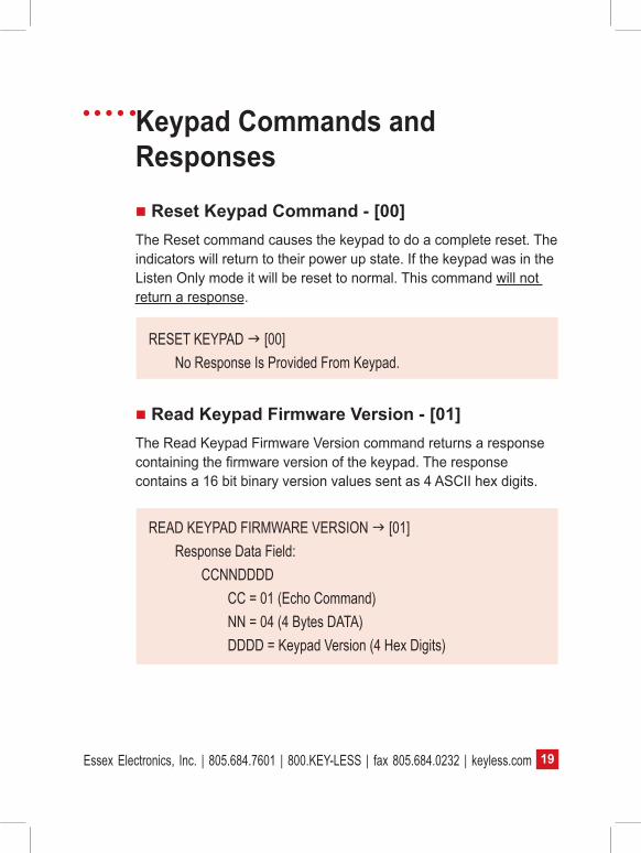
Keypad Commands and Responses Reset Keypad Command - [00]The Reset command causes the keypad to do a complete reset. The indicators will return to their power up state. If the keypad was in the Listen Only mode it will be reset to normal. This command will not return a response.
RESET KEYPAD [00] No Response Is Provided From Keypad.
Read Keypad Firmware Version - [01]The Read Keypad Firmware Version command returns a response containing the firmware version of the keypad. The response contains a 16 bit binary version values sent as 4 ASCII hex digits.
READ KEYPAD FIRMWARE VERSION [01] Response Data Field: CCNNDDDD CC = 01 (Echo Command) NN = 04 (4 Bytes DATA) DDDD = Keypad Version (4 Hex Digits)

Essex Electronics, Inc. | 805.684.7601 | 800.KEY-LESS | fax 805.684.0232 | keyless.com20
Set Listen Only Mode - [02]The Set Listen Only Mode command puts the keypad into the Listen Only Mode. In Listen Only Mode, the keypad will act on any commands sent to it, but it will not send any Response or Event Data. It is provided mainly to disable a keypad that may be malfunctioning. Once the keypad is in Listen Only Mode, it can only be returned to normal mode with a Reset Command or a Power Reset. This command will not return a response.
SET LISTEN ONLY MODE [02] No Response Is Provided From Keypad.

21Essex Electronics, Inc. | 805.684.7601 | 800.KEY-LESS | fax 805.684.0232 | keyless.com
Read Keypad Counters - [03]The Read Keypad Counters command returns a response containing the keypad communication counter values. The response contains 5 groups of 16 bit binary counter values sent as 4 ASCII hex digits. The BUS Message Count is the number of packets that the keypad has received. The BUS Error Count is the number of packets the keypad received that contained an error. The BUS Exception Count is the number of packets received that were not framed correctly. The BUS Overflow Count is the number of packets received that exceed 255 characers. The BUS SLAVE Message Count is the number of packets that the keypad has sent. The SLAVE NAK Count is the number of error response packets the keypad has sent.
READ KEYPAD COUNTER VALUES [03] Response Data Frame: CCNNTTTTVVVVWWWWXXXXYYYYZZZZ CC = 03 (Echo Command) NN = 18 (0x18 {24 Dec) Bytes Of DATA) TTTT = BUS Message Count (4 Hex Digits) VVVV = BUS Error Count (4 Hex Digits) WWWW = BUS Exception Count (4 Hex Digits) XXXX = BUS Overflow Count (4 Hex Digits) YYYY = SLAVE Message Count (4 Hex Digits) ZZZZ = SLAVE NAK Count (4 Hex Digits)
Essex Electronics, Inc. | 805.684.7601 | 800.KEY-LESS | fax 805.684.0232 | keyless.com22
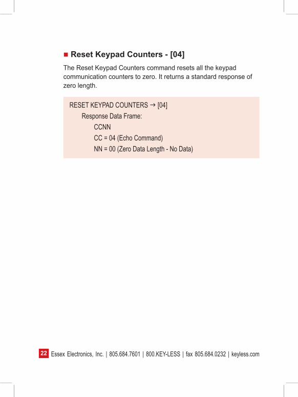
Reset Keypad Counters - [04]The Reset Keypad Counters command resets all the keypad communication counters to zero. It returns a standard response of zero length.
RESET KEYPAD COUNTERS [04] Response Data Frame: CCNN CC = 04 (Echo Command) NN = 00 (Zero Data Length - No Data)
23Essex Electronics, Inc. | 805.684.7601 | 800.KEY-LESS | fax 805.684.0232 | keyless.com
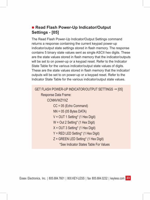
Read Flash Power-Up Indicator/Output Settings - [05]The Read Flash Power-Up Indicator/Output Settings command returns a response containing the current keypad power-up indicator/output state settings stored in flash memory. The response contains 5 binary state values sent as single ASCII hex digits. These are the state values stored in flash memory that the indicator/outputs will be set to on power-up or a keypad reset. Refer to the Indicator State Table for the various indicator/output state values of digits. These are the state values stored in flash memory that the indicator/outputs will be set to on power-up or a keypad reset. Refer to the Indicator State Table for the various indicator/output state values.
GET FLASH POWER-UP INDICATOR/OUTPUT SETTINGS [05] Response Data Frame: CCNNVWZYXZ CC = 05 (Echo Command) NN = 05 (05 Bytes DATA) V = OUT 1 Setting* (1 Hex Digit) W = Out 2 Setting* (1 Hex Digit) X = OUT 3 Setting* (1 Hex Digit) Y = RED LED Setting* (1 Hex Digit) Z = GREEN LED Setting* (1 Hex Digit) *See Indicator States Table For Values

Essex Electronics, Inc. | 805.684.7601 | 800.KEY-LESS | fax 805.684.0232 | keyless.com24
Set Flash Power-Up Indicator/Output Settings - [06]The Set Flash Power-Up Indicator/Output Settings command sets the power-up indicator/output state values in flash memory. These values are used to set the state of the indicator/outputs on a power-up or reset. The command requires 5 additional data digits after the [06] command digits. These digits are the 5 indicator/output state values to set, sent as single ASCII hex digits. Refer to the Indicator State Table for the various indicator/output state values. After executing this command, the keypad will write the new values to flash, then halt operation for 50 milliseconds. It will then reset the keypad. This command will not return a response.
WARNING: This command writes to Flash Memory. The Flash Memory can only be written to a LIMITED number of times (approx. 100,000 write cycles). DO NOT USE IT for every keypad state change. It is only provided to set up the special case of setting the indicator/outputs states when a power or keypad reset occurs. Overuse will cause the Flash Memory to Fail.
SET FLASH POWER-UP Indicator/Output SETTINGS [06]This command is followed by 5 Hex Digits which set the individual Indicator/Output Power-Up States.The complete command takes the form: 06VWXYZ V = OUTPUT 1 State Value* (1 Hex Digit) W = OUTPUT 2 State Value* (1 Hex Digit) X = OUTPUT 3 State Value* (1 Hex Digit) Y = RED LED State Value* (1 Hex Digit) Z = GREEN LED State Value* (1 Hex Digit) *See Indicator States Table For ValuesNo response from keypadKeypad Is Reset

25Essex Electronics, Inc. | 805.684.7601 | 800.KEY-LESS | fax 805.684.0232 | keyless.com
Disable Keypad Input - [10]The Disable Keypad command puts the keypad in a mode where no data will be accepted. If a key is pressed, there will be no beep or LED flash and the input will be ignored. No Event Packet will be sent if the keypad has an Event Mode enabled. It returns a standard response of zero length.
DISABLE KEYPAD INPUT [10] Response Data Frame: CCNN CC = 10 (Echo Command) NN = 00 (Zero Data Length - No Data)
Enable Keypad Input - [11]The Enable Keypad command restores the keypad mode to normal data input operation. This command is used to exit Disable Keypad Mode. It returns a standard response of zero length.
ENABLE KEYPAD INPUT [11] Response Data Frame: CCNN CC = 11 (Echo Command) NN = 00 (Zero Data Length - No Data)

Essex Electronics, Inc. | 805.684.7601 | 800.KEY-LESS | fax 805.684.0232 | keyless.com26
Tamper Alarm For 15 Seconds - [12]The Tamper Alarm 15 Sec command will put the keypad in Tamper Mode for 15 seconds. When the keypad is in Tamper Mode, it will flash both LEDs and output a continuous beep for 15 seconds. During this time, the keypad will be Disabled and will not accept any data. At the end of the 15 second Tamper Interval, the keypad will return to normal operation. It returns a standard response of zero length.
TAMPER ALARM FOR 15 SECONDS [12] Response Data Frame: CCNN CC = 12 (Echo Command) NN = 00 (Zero Data Length - No Data)
Tamper Alarm For 30 Seconds - [13]The Tamper Alarm 30 Sec command acts the same as the Tamper Alarm 15 Sec except the Tamper Interval is set to 30 Seconds. It returns a standard response of zero length.
TAMPER ALARM FOR 30 SECONDS [13] Response Data Frame: CCNN CC = 13 (Echo Command) NN = 00 (Zero Data Length - No Data)
27Essex Electronics, Inc. | 805.684.7601 | 800.KEY-LESS | fax 805.684.0232 | keyless.com
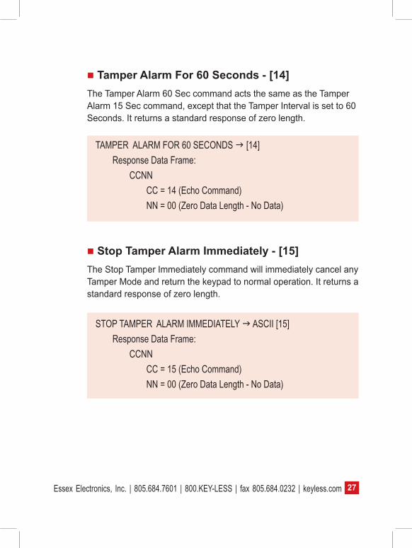
Tamper Alarm For 60 Seconds - [14]The Tamper Alarm 60 Sec command acts the same as the Tamper Alarm 15 Sec command, except that the Tamper Interval is set to 60 Seconds. It returns a standard response of zero length.
TAMPER ALARM FOR 60 SECONDS [14] Response Data Frame: CCNN CC = 14 (Echo Command) NN = 00 (Zero Data Length - No Data)
Stop Tamper Alarm Immediately - [15]The Stop Tamper Immediately command will immediately cancel any Tamper Mode and return the keypad to normal operation. It returns a standard response of zero length.
STOP TAMPER ALARM IMMEDIATELY ASCII [15] Response Data Frame: CCNN CC = 15 (Echo Command) NN = 00 (Zero Data Length - No Data)

Essex Electronics, Inc. | 805.684.7601 | 800.KEY-LESS | fax 805.684.0232 | keyless.com28
Read Keypad Input Data - [20]The Read Keypad Input Data command will return any data that has been input to the keypad since the last Read command. Data is input to the keypad by the operator entering the “#” key, which will enter the data into the keypad buffer. Entering the “*” key will erase this buffer. The keypad response will contain a 2-digit value (NN) indicating the number of digits that were input. If this value is [00] zero, then no data was input and no data digits will follow. If the value is 1 to hex F [01- 0F] (the maximum number of digits that may be entered is 15), then that is the number of digits that were input and that is the number of digits that will follow the 2 (NN) digits. These ASCII hex digits will be between 0 and 9 [0-9]. The values [0-9] are the keys 0-9..
Notes on keypad entries: if more than 15 digits are entered, the keypad will respond with a 2 second tone, indicating an error, which will clear the buffer. If a keypad sequence is started but the “#” button is not used to enter this data, after 10 seconds of inactivity the keypad will automatically clear this buffer, which is indicated with a double beep and blink (if the LEDs are set for this).
READ KEYPAD INPUT DATA [20] Response Data Frame: CCNN~ CC = 20 (Echo Command) NN = Number of Digits Input If 00 No Keypad Data Input ~ = Keypad Input Digits Of Length NN
29Essex Electronics, Inc. | 805.684.7601 | 800.KEY-LESS | fax 805.684.0232 | keyless.com
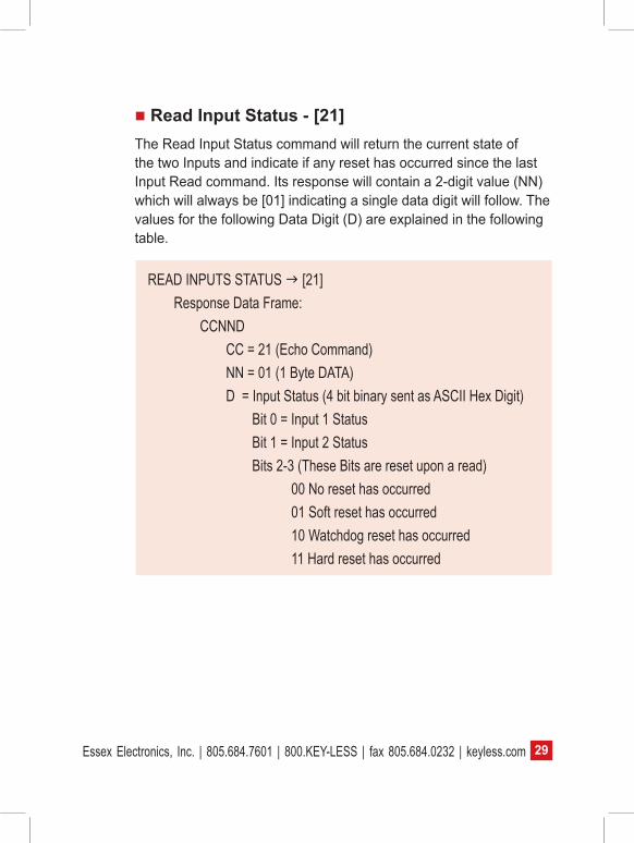
Read Input Status - [21]The Read Input Status command will return the current state of the two Inputs and indicate if any reset has occurred since the last Input Read command. Its response will contain a 2-digit value (NN) which will always be [01] indicating a single data digit will follow. The values for the following Data Digit (D) are explained in the following table.
READ INPUTS STATUS [21] Response Data Frame: CCNND CC = 21 (Echo Command) NN = 01 (1 Byte DATA) D = Input Status (4 bit binary sent as ASCII Hex Digit) Bit 0 = Input 1 Status Bit 1 = Input 2 Status Bits 2-3 (These Bits are reset upon a read) 00 No reset has occurred 01 Soft reset has occurred 10 Watchdog reset has occurred 11 Hard reset has occurred

Essex Electronics, Inc. | 805.684.7601 | 800.KEY-LESS | fax 805.684.0232 | keyless.com30
Read Keypad Input Data & Input Status - [22]The Read Keypad Input Data & Input Status command will return both Keypad Data & Input Status in a single response. Its response will contain a 2-digit value (NN) indicating the number of digits that will follow. If this value is 1 [01], then no data was input and only a single Input Status digit will follow. If the value is greater than 1, then that number of Keypad data digits minus 1 will follow the Input Status digit. These Keypad Data digits and Input Status digit take the same form as discussed in the two previous commands. (Read Keypad Data & Read Input Status.)
GET KEYPAD INPUT DATA & INPUTS STATUS [22] Response Data Frame: CCNND~ CC = 22 (Echo Command) NN = Number of KEYPAD Chars +1 If 01 No Keypad Data Input Data is only Input Status Byte D = Input Status (See D In Command 21 Above) ~ = Keypad Input Digits of Length NN-1

31Essex Electronics, Inc. | 805.684.7601 | 800.KEY-LESS | fax 805.684.0232 | keyless.com
Read Current Indicator/Outputs States - [27]The Read Current Indicator/Output State command will return the current states of all six of the outputs and keypad indicators. Its response will return a 2-digit value of [06] to indicate that 6 data digits will follow (NN). These digits are followed by 6 data digits. These 6 digits contain the current state of the individual output /indicators. The order of the output / indicator digits (VWXYZQ) is listed in the table below. Each of these will have a value that indicates the state of that particular output / indicator. The states that these values represent are listed in the Indicator State Table.
READ CURRENT INDICAOR/OUTPUT STATES [27] Response Data Frame: CCNNVWXYZQ CC = 27 (Echo Command) NN = 06 (06 Bytes DATA) V = OUTPUT 1 State Value* (1 Hex Digit) W = OUTPUT 2 State Value* (1 Hex Digit) X = OUTPUT 3 State Value* (1 Hex Digit) Y = RED LED State Value* (1 Hex Digit) Z = GREEN LED State Value* (1 Hex Digit) Q = Beeper/Tamper State Value* (1 Hex Digit) *See Indicator States Table for Values
Essex Electronics, Inc. | 805.684.7601 | 800.KEY-LESS | fax 805.684.0232 | keyless.com32
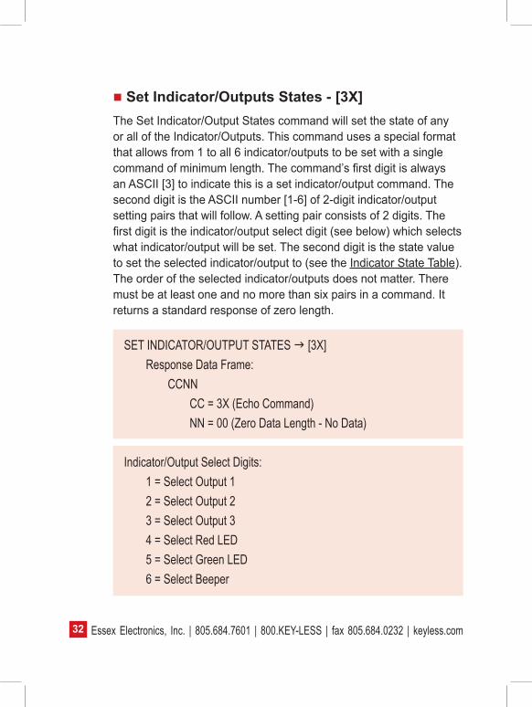
Set Indicator/Outputs States - [3X]The Set Indicator/Output States command will set the state of any or all of the Indicator/Outputs. This command uses a special format that allows from 1 to all 6 indicator/outputs to be set with a single command of minimum length. The command’s first digit is always an ASCII [3] to indicate this is a set indicator/output command. The second digit is the ASCII number [1-6] of 2-digit indicator/output setting pairs that will follow. A setting pair consists of 2 digits. The first digit is the indicator/output select digit (see below) which selects what indicator/output will be set. The second digit is the state value to set the selected indicator/output to (see the Indicator State Table). The order of the selected indicator/outputs does not matter. There must be at least one and no more than six pairs in a command. It returns a standard response of zero length.
SET INDICATOR/OUTPUT STATES [3X] Response Data Frame: CCNN CC = 3X (Echo Command) NN = 00 (Zero Data Length - No Data)
Indicator/Output Select Digits: 1 = Select Output 1 2 = Select Output 2 3 = Select Output 3 4 = Select Red LED 5 = Select Green LED 6 = Select Beeper
33Essex Electronics, Inc. | 805.684.7601 | 800.KEY-LESS | fax 805.684.0232 | keyless.com
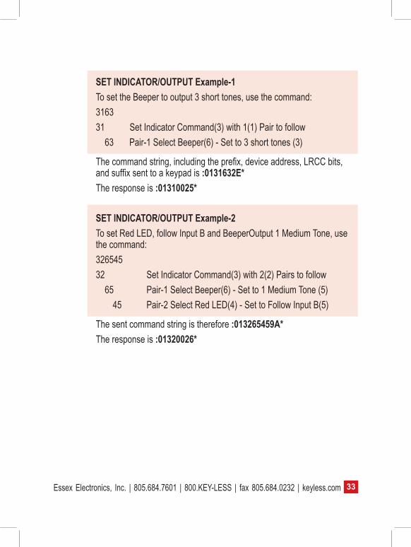
SET INDICATOR/OUTPUT Example-1To set the Beeper to output 3 short tones, use the command: 316331 Set Indicator Command(3) with 1(1) Pair to follow 63 Pair-1 Select Beeper(6) - Set to 3 short tones (3)
The command string, including the prefix, device address, LRCC bits, and suffix sent to a keypad is :0131632E*The response is :01310025* SET INDICATOR/OUTPUT Example-2To set Red LED, follow Input B and BeeperOutput 1 Medium Tone, use the command:32654532 Set Indicator Command(3) with 2(2) Pairs to follow 65 Pair-1 Select Beeper(6) - Set to 1 Medium Tone (5) 45 Pair-2 Select Red LED(4) - Set to Follow Input B(5)
The sent command string is therefore :013265459A*The response is :01320026*

Essex Electronics, Inc. | 805.684.7601 | 800.KEY-LESS | fax 805.684.0232 | keyless.com34
SET INDICATOR/OUTPUT Example-3To set Output 1 Pulse, Output 2 On, Output 3 Off, Red LED On, Green LED Fast Flash and Beeper Output Long Tone, use the command:3612213041596736 Set Indicator Command(3) With 6(6) Pairs To Follow 12 Pair-1 Select Output 1(1) - Set to Pulse(2) 21 Pair-2 Select Output 2(2) - Set to On(1) 30 Pair-3 Select Output 3(3) - Set to Off(0) 41 Pair-4 Select Red LED(4) - Set to On(1) 59 Pair-5 Select Green LED(5) - Set to Fast Flash(9) 67 Pair-6 Select Beeper(6) - Set to Long Beep(7)
The sent command is therefore :013612213041596733*The response is :0136002A*
INDICATOR STATE TABLEOUTPUT - SET/READ STATE VALUES (VWX): 0 = Off 1 = On 2 = 1 Second PulseLED - SET/READ STATE VALUES (YZ): 0 = Off 1 = On 2 = Off & Beeper Flash (each keypad entry will beep, and the LED will flash feedback for the user) 3 = On & Beeper Flash (each keypad entry will beep, and the LED will blink feedback for the user) 4 = Track Input A (LED will respond to the Input A state) 5 = Track Input B (LED will respond to the Input B state)

35Essex Electronics, Inc. | 805.684.7601 | 800.KEY-LESS | fax 805.684.0232 | keyless.com
INDICATOR STATE TABLE, cont’d. 6 = Track Input A & Beeper Flash (combines states) 7 = Track Input B & Beeper Flash (combines states) 8 = Slow Blink 9 = Fast BlinkBEEPER/TAMPER - READ STATE VALUES (Q): 0 = Beeper Off / Tamper Alarm Inactive 1 = Beeper On / Tamper Alarm Inactive 2 = Beeper Off / Tamper Alarm Active 3 = Beeper On / Tamper Alarm ActiveBEEPER - SET STATE VALUES: 0 = Off 1 = 1 Short Beep 2 = 2 Short Beeps 3 = 3 Short Beeps 4 = 4 Short Beeps 5 = 1 Medium Beep 6 = 2 Medium Beeps 7 = 1 Long Beep 8 = Force Beeper On (Only a “Beeper Off” command will clear a “Forced Beeper On” command)

Essex Electronics, Inc. | 805.684.7601 | 800.KEY-LESS | fax 805.684.0232 | keyless.com36
How The LRCC Values Are CalculatedThe 2-byte LRCC value is calculated using all the ASCII characters in the packet except the start character [:] and the end character [*]. The ASCII value of each of these characters is added together using an 8 bit accumulator where the overflow is discarded. This 8 bit value becomes the LRCC value which is sent as 2 ASCII Hex digits.
Example-1 Packet Data To Get Current I/O From Keypad 01: 0127
Character 8 Bit Accumulator0x000 [0x30] +→ 0x301 [0x31] +→ 0x612 [0x32] +→ 0x937 [0x37] +→ 0xCA
The LRCC Values for this packet is 0xCA and sent as ASCII Chars “C” “A”. The Complete Formatted Packet With LRCC = :0127CA*

37Essex Electronics, Inc. | 805.684.7601 | 800.KEY-LESS | fax 805.684.0232 | keyless.com
Example-2 Packet Data To Turn Keypad 01 Red LED OFF: 013140
Character 8 Bit Accumulator0x000 [0x30] +→ 0x301 [0x31] +→ 0x613 [0x33] +→ 0x941 [0x31] +→ 0xC54 [0x34] +→ 0xF90 [0x30] +→ 0x29 (8 Bit Value, Carries Are Discarded)
The LRCC Values for this packet is 0x29 and sent as ASCII Chars “2” “9”. The Complete Formatted Packet With LRCC = :01314029*
Example-3 Packet Data To Force Keypad 1F Beeper ON: 1F3168
Character 8 Bit Accumulator0x001 [0x31] +→ 0x31F [0x46] +→ 0x773 [0x33] +→ 0xAA1 [0x31] +→ 0xDB6 [0x36] +→ 0x1118 [0x38] +→ 0x149 (the higher order byte is discarded)
The LRCC Values for this packet is 0x49 and sent as ASCII Chars “4” “9”. The Complete Formatted Packet With LRCC = :1F316849*

Essex Electronics, Inc. | 805.684.7601 | 800.KEY-LESS | fax 805.684.0232 | keyless.com38
Frequently Asked Questions“I am a facility manager/end user and my keypad no longer unlocks my door. What do I do?”
Check that the keypad is still functioning and each key press gives a beep and the red LED blinks. If yes, then the keypad is still good.
Although the keypad is the “face” of your system, it is only a part of that system, and there are other elements that complete that system. This keypad was provided to an OEM (Original Equipment Manufacturer) and is part of their system. It is recommended that you contact that company.
“I am an installer and the brand new keypad won’t work at all. What shall I do?”
Check that the keypad has power – at least 12V DC on the red and black wires to the keypad.
Check that the 12V DC jumper is installed on only one pin if 12V is applied, and that the jumper is installed across two pins if only 5V is applied.
Check that the keypad connector does not have bent or broken pins and the mating connector has the wires seated and locked in place.
Make sure that the power supply has the correct polarity applied to the keypad – positive voltage on the red lead and circuit return on the black lead.
Make sure that the keypad is correctly configured for communications to the controller and has the correct device address set.
“I’ve just installed the keypad and there are a number of wires on the harness that are not connected to anything. What do I

39Essex Electronics, Inc. | 805.684.7601 | 800.KEY-LESS | fax 805.684.0232 | keyless.com
do with them?”
Trim them back so that they do not short to anything or to each other, and stow them so that they are not interfering with the placement of the keypad.
The tan wire should be connected to the closest facility earth grounding. This may be the metal conduit that the cable wiring is going through, if it is so attached to facility earth ground. It may also be wired to the power ground line, which is the “green” conductor associated with AC power.
Note that the data and DC lines for the keypad should not be in the same conduit or races as facility power for the building, but in their own conduit or races.
“I need to install one of your keypads in a coastal marine environment. What precautions may I take to better protect this equipment in this environment?”
Although our keypads are made from durable materials and should withstand such environments, they will benefit from two added precautions:
1. The application of a dielectric-type grease should be used after all electrical connections are spliced. This will better protect such connections for corrosion and damage from the environment.
2. The application of a bead of sealant around the installation of the keypad should be used to block moisture from wicking into the electrical connections.
“My customer is complaining that there is some wear on the face of the keypad, indicating the most used buttons. How should I resolve this?”
Although our keypads are made from durable materials, the use of

Essex Electronics, Inc. | 805.684.7601 | 800.KEY-LESS | fax 805.684.0232 | keyless.com40
car keys or other hard elements, such as batons or tools to press the buttons of the keypad, may damage the face of the keypad. The end user should be cautioned against using such devices and only use their fingers to operate the keypad. In cold climates, the fingers may remain gloved.
Such damage is cosmetic in nature, and the keypad should continue to operate. It is recommended that the pin or access code be changed so that different keys are used to grant access.
Sometimes the wear may be too great to reliably use the keypad and the keypad may need to be replaced. Please review our General Warranty Policy: http://www.keyless.com/PDF/GeneralWarranty.pdf
“I am a developer creating a system to use your keypad. How do I communicate with the keypad?”
The keypad will need to be set for the speed and protocol of your system. This may be done using the keypad configuration procedure found in this Installation & Instruction Manual.
Once the communications settings are complete, the keypad will need to be connected to your system using an RS485 adapter to whatever interface you require. The adapter settings will also have to be set to match the keypad.
We do not provide any software for this communication. At a basic level, for testing, a terminal program from any third party may be used if the packet format is observed and commands are built up by hand.
The communications packet protocol will have to be sent and received as specified in the above manual.
Once communications are established, the keypad will respond to any command sent over the communications link.

41Essex Electronics, Inc. | 805.684.7601 | 800.KEY-LESS | fax 805.684.0232 | keyless.com
“I need to connect more than one keypad to my system. How is this done?”
Each keypad may be set to a specific address unique to that keypad.
This address is any number from 000 to 127.
Hardware connections to the RS-485 bus are a daisy chain, with each keypad connected to the next keypad directly. The keypad furthest from the RS-485 adapter/controller should have a termination resistor across this bus (the keypad has a jumper setting).
The adapter controller may be anywhere on this daisy chain.
“I need to attach a relay so that it may control my device through the keypad. How is this done?”
The keypad has four outputs, three of which may be controlled through the keypad commands. The fourth, associated with the blue wire, will activate with any key press and will be active for 30 seconds. This output is usually used to turn on an external light or closed circuit television camera or other functions that are determined by the original developer.
All four outputs are open collector active low and can drive up to a 1/4A load, from 5V DC to 28V DC.
Most 12V relays will work for most applications, such as door strike, magnetic lock, or external motor control. Care should be taken for high magnetic loads so that the relay contacts do not suffer from excessive peak current loads (a “snubber” circuit).

Essex Electronics, Inc. | 805.684.7601 | 800.KEY-LESS | fax 805.684.0232 | keyless.com42
Notes

43Essex Electronics, Inc. | 805.684.7601 | 800.KEY-LESS | fax 805.684.0232 | keyless.com
Notes
Essex Electronics, Inc. | 805.684.7601 | 800.KEY-LESS | fax 805.684.0232 | keyless.com44
Warranty & Repairs General Warranty Policy (effective date May 1, 2014)
Essex Electronics Inc. (“Essex”) warrants that at the time of original purchase from Essex the products specified below are free from defects in workmanship and material. Subject to the conditions and limitations set forth below, Essex will, at its option, either repair or replace any part of its products that prove defective by reason of improper workmanship or materials. Repaired parts or replacement products will be provided by Essex on an exchange basis, and will be either new or refurbished to be functionally equivalent to new. Essex reserves the right to discontinue a product for any reason, without notice, at any time. If a product that has been discontinued proves defective and if Essex is unable to repair or replace the product, within the terms expressed in this Limited Warranty, a substitute product may be provided at Essex’s election, as a replacement for the original discontinued product.
This Limited Warranty extends only to the original retail or wholesale Buyer and the original site of installation. It does not cover any damage to this product or parts thereof, if the product is installed in violation of the applicable codes or ordinances, or is not installed and used in accordance with our installation instructions. This warranty applies only to standard Essex products purchased as completed assemblies and does not cover custom products (excluding custom graphics) nor does it cover products purchased as subassemblies. This warranty will only include the normal operating life of the LED’s and relays as specified by the manufacturer. It does not cover any damage that results from accident, abuse, misuse, natural disaster, insufficient or excessive electrical supply, abnormal mechanical or environmental conditions, or any unauthorized disassembly, repair, or modification. This Limited Warranty also does not apply to any product on which the original identification or date of manufacture information has been

45Essex Electronics, Inc. | 805.684.7601 | 800.KEY-LESS | fax 805.684.0232 | keyless.com
altered, obliterated or removed. In no event shall Essex be liable for any damage to persons, property or area surrounding the installation site caused by any malfunction of the product manufactured or supplied by Essex.
Essex will not pay, nor be responsible for shipping, transportation or delivery charges, or other cost of removal of a defective product or installation of a replacement product. The original component replaced under this Limited Warranty in any system shall become the property of Essex and as such will, at our request, be returned to our factory with transportation charges paid by the Buyer.
Limited Lifetime Warranty: Products carrying Limited Lifetime Warranty against defects in materials and workmanship are Essex KTP Series Keypads, K1 Series, SKE Series Keypads, KE-265 Series, PEB Series and Hand-E-Tap Series Door Access Switches. Only products with a manufactured date of 5/1/06 to the present date are covered by this Limited Lifetime Warranty.
Limited 18 Month Warranty: Products carrying an 18 month warranty against defects in materials and workmanship include External Power Supplies, Hand-E-Wave™, HID Edge® controllers, products with embedded 125 kHz and 13.56 MHz Card Reader processors including the PiezoProx®, iSMART™, K-Prox, RoxProx™, RoxClass™, T-Prox™, iRox™ and iRox Plus™.
Limited 3 Year Warranty: Essex KE-1700 Series and AKE-5 Series are covered by a 3 year limited warranty against defects in materials and workmanship.
Limited 2 Year Warranty: Essex products used for Elevator access control applications are covered by a 2 year limited warranty. This includes the KE-1000, KE-1900 and SKE-34 used in an elevator access control installation.
Essex Electronics, Inc.’s liability and Buyer’s remedy under this warranty is limited to the repair or replacement at Seller’s election

Essex Electronics, Inc. | 805.684.7601 | 800.KEY-LESS | fax 805.684.0232 | keyless.com46
of the product, or parts thereof, returned to Essex Electronics Inc. at Buyer’s expense and shown to Essex Electronics Inc.’s reasonable satisfaction to have been defective.
Notice of any defect must be sent in writing to Essex Electronics, Inc., 1130 Mark Avenue, Carpinteria, California, 93013, USA and must include the date code of the unit, description of the defect and factory assigned Return Authorization #. Upon receipt of such notification, Essex will determine whether to repair or replace. We also reserve the right to have our representative make any inspection or repairs, or furnish replacements.
ESSEX RESERVES THE RIGHT TO AMEND THIS GENERAL WARRANTY POLICY AS REQUIRED.
Disclaimer of Warranties: Limitation of Buyer’s RemediesExcept for the repair or replacement at seller’s option which is expressly set forth above, Essex Electronics Inc. extends no warranty of any kind, express or implied, and disclaims any implied warranty of merchantability or suitability for purpose for which sold, with respect to the keypads, keyless entry coded access system or accessories. Except for the limited repair or replacement specified above, under no circumstances will Essex Electronics Inc. be liable to buyer under or in connection with any manufacture or sale of any of the products set forth above under any tort, negligence, strict liability, contract or other legal or equitable theory, or for incidental or consequential damages, or buyer’s cost of effecting insurance coverage.
The foregoing limited warranty expressed herein constitutes the sole and entire warranty with respect to the products set forth above and is in place of any and all other warranties, express or implied.
This warranty may not be expanded or extended by any oral representation, written sales information, advertising, drawings or otherwise. Essex Electronics Inc. is not responsible hereunder for incidental damage to person or property, or other incidental or

47Essex Electronics, Inc. | 805.684.7601 | 800.KEY-LESS | fax 805.684.0232 | keyless.com
consequential damages. The remedies of the buyer shall be limited to those provided in this limited lifetime warranty to the exclusion of any and all other remedies, including, without limitation, incidental or consequential damages.
This Limited Lifetime Warranty shall be governed by and interpreted in accordance with the California Uniform Commercial Code and by the procedural laws of the State of California. Any lawsuit or other action which arises out of, relates to, or is in connection with the manufacture or sale of the products set forth above shall be governed by California law, and the venue for any such action shall be the Superior Court of the State of California in and for Santa Barbara County, California. Repair PolicyShould it be necessary for a component or a system to be returned for repair, it must be accompanied with an RA# (Return Authorization Number) issued by the factory. Please call 1-800-KEYLESS (800-539-5377) to obtain an RA#. All returns must be sent to the factory freight prepaid. Collect shipments will not be accepted at any time. Standard turnaround time is ten (10) working days from the date of receipt. Repaired components will be returned UPS Ground (or equivalent). Any other shipping requests or instructions will be at the customer’s expense.At the factory’s discretion, warranty repairs will include repair or replacement, update and testing. Returns and repairs out of the warranty period or in warranty with damage not covered under warranty shall be subject to a repair charge. All non-warranty repair freight charges are paid for by the customer. Non-warranty repair charges must be paid by credit card. (Factory Authorized Distributors are subject to standard terms).

Essex Electronics, Inc. | 805.684.7601 | 800.KEY-LESS | fax 805.684.0232 | keyless.com