RRDPAE 2008 HAW Hamburg Mihaela Florentina Ni … 72 Mihaela Florentina Ni ... Take-off thrust, or...
28
Aircraft Design Studies Based on the ATR 72 Mihaela Florentina Niţă Supervisor: Prof. Dr.-Ing. Dieter Scholz HAW Hamburg RRDPAE 2008 Recent Research and Design Progress in Aeronautical Engineering and its Influence on Education Brno University of Technology, Czech Republic, 16-17 October 2008
-
Upload
hoangthien -
Category
Documents
-
view
215 -
download
2
Transcript of RRDPAE 2008 HAW Hamburg Mihaela Florentina Ni … 72 Mihaela Florentina Ni ... Take-off thrust, or...

Aircraft Design StudiesBased on the
ATR 72
Mihaela Florentina NiţăSupervisor: Prof. Dr.-Ing. Dieter Scholz
HAW HamburgRRDPAE 2008
Recent Research and Design Progress in Aeronautical Engineering and its Influence on Education
Brno University of Technology, Czech Republic, 16-17 October 2008
Info
Presentation during "RRDPAE 2008", Brno, 16. -17. October 2008 Download this file from: http://paper.ProfScholz.de Presentation related to Master Thesis: Mihaela Florentina Nita: "Aircraft Design Studies Based on the ATR". Hamburg University of Applied Sciences, 2008 Download the thesis from: http://bibliothek.ProfScholz.de

– Preliminary sizing
(Paper on RRDPAE CD)
– Conceptual Design(Master Thesis on WWW)
Two Design Steps
Emphasis of this presentation

• Preliminary sizing
– Gives input parameters for the conceptual design:
» Maximum take-off mass,» Fuel mass,» Maximum operating empty mass,» Wing area, » Take-off thrust, or take-off power,
Overview
mMTOFm
mOESW
TTO TOP

• Conceptual design
Overview

• The Fuselage– Requirements:
» Passengers comfort
» Drag» Weight
– Cross section:
» Given: Number of passengers
» Yields: Number of seats abreast
and number of aisles
(CS 25.817)
Fuselage
70PAXn =
0.45 4SA PAXn n= ⋅ =
6 1SAn Aisle≤ ⇒

Fuselage
» Interior diameter of the fuselage
» Exterior diameter of the fuselage
, , , ,0.084 0.045 2.77F O F I F I F Od d d m d d m∆ = − = + ⋅ ⇔ =
, (2 ) 2 0.025 2.57F Id Bench width Aisle width m m m= × + + × =EmpiricalEquation

– Cabin and fuselage:» Seat pitch:
» Cabin Length
» Fuselage length
» Emergency exits: 2+2 type I and III
19.25PAXCABIN CABIN
SA
nl k mn
= ⋅ =
1.4 4 27.13F CABIN Fl l d m m= + ⋅ + =
Fuselage
31in 0,78 m;1 mCABINk
==
An average seat pitchincluding galleys,lavatories
Cockpit
length
Tail length

– Other parameters:» Slenderness parameter
Important parameter that determines drag and structural weight
9.79 10FF
F
ld
λ = = ≈
Fuselage

Wing
All interconnected
!!!
• The Wing– Design boundaries

Wing
– Design method

Wing
261.3WS m=
NACA 43018NACA 43013
– Results
0.41CRM =
12A =27.13b m=
025 3ϕ =
25( / ) cos 0.141t u v wt DD L Mt c k M C kϕ= ⋅ ⋅ ⋅ ⋅ =
Non linearregression
Chosenairfoil: NACA
430xx
( / ) 18%( / ) 13%
r
t
t ct c
==
, 00 0.4 4L CR
w tL
Ci
Cα
α ε= + − ⋅ =
Abbot, Pankhurst
03tε = −
00Wν =250.0360.45 opt e or statisticsϕλ − ⋅= ⋅
/ 0 .59t rc cλ = =

Wing
2 2.6[(1 ) ]r
k i
bc mA λ η λ λ
= =− + +
1.5t rc c mλ= =
21.5 3 3
tank tank,nec2
1 10.54 ( / ) 9.3 4.5(1 )W rV S t c m V m
Aλ τ λ τ
λ+ ⋅ + ⋅= ⋅ ⋅ ⋅ ⋅ = > =
+
From preliminarysizing
( / ) 0.72( / )
t
r
t ct c
τ = =where

High Lift System
• The high lift system– Design methodStart
Statistical reasearch
CL,max
Increase inLift calculation
Verifyequation
yesno
Stop
Iterativeprocess
,max ,max, 1.1 2.2L L INITIAL SIZINGC C= ⋅ =
,max, ,max, ,max ,max,0.95 L f L s L L cleanC C C C⋅ ∆ + ∆ ≥ −
: type of flap double slotted flap and slats
,max, 1 2 3 ,max( ) 1.089L f L basec k k k c∆ = ∆ =
,,max, ,max, 0.679W fL f L f
W
SC c K
S ϕ∆ = ∆ ⋅ ⋅ ='
,max, , ,max max 0.766L s l fcc ccδ δη η δ∆ = =
,,max, ,max, ,cos 0.613W sL s L s H L
W
SC c
Sϕ∆ = ∆ ⋅ ⋅ =
1.3 0.9≥
DATCOM
Empennage
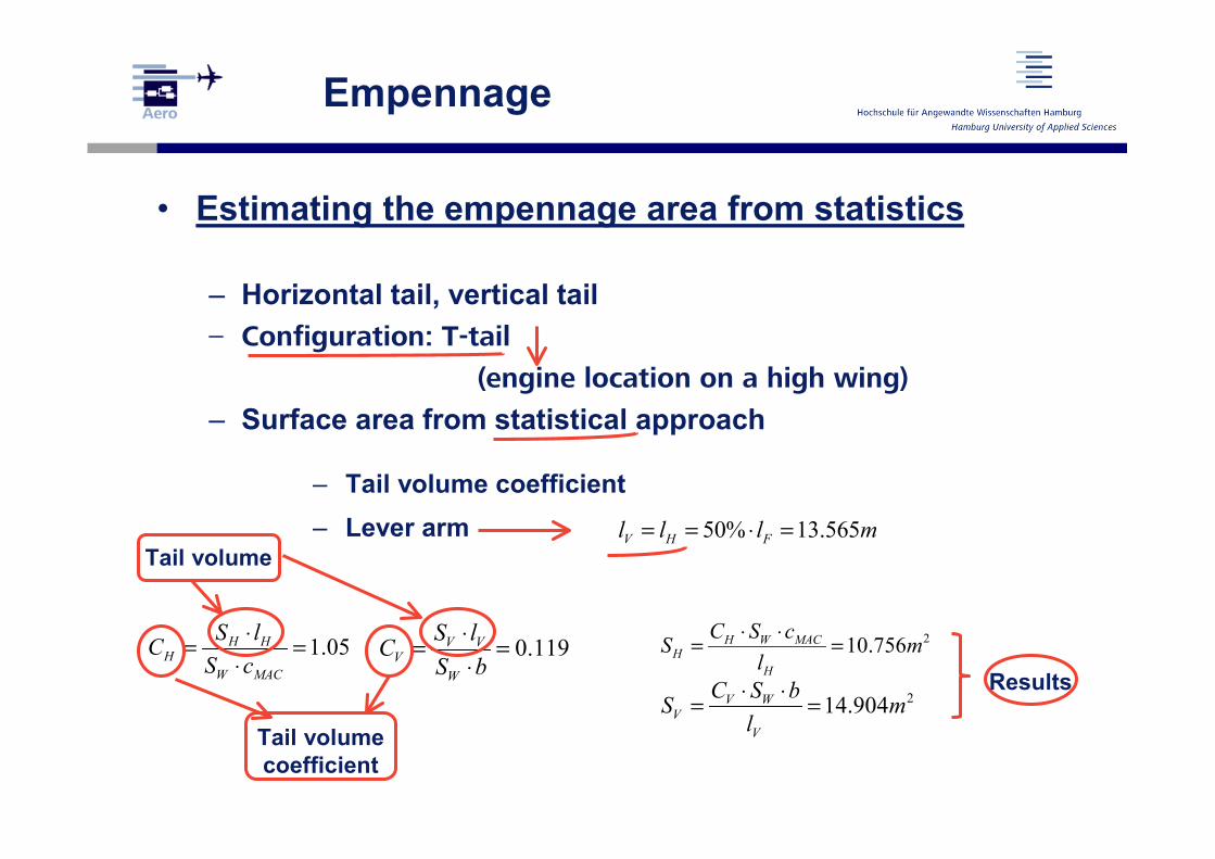
• Estimating the empennage area from statistics
– Horizontal tail, vertical tail– Configuration: T-tail
(engine location on a high wing)
– Surface area from statistical approach
– Tail volume coefficient– Lever arm
1.05H HH
W MAC
S lCS c
⋅= =⋅
0.119V VV
W
S lCS b
⋅= =⋅
Tail volume
Tail volumecoefficient
50% 13.565V H Fl l l m= = ⋅ =
210.756H W MACH
H
C S cS ml
⋅ ⋅= =
214.904V WV
V
C S bS ml⋅ ⋅= =
Results

Empennage
– Other parameters
– Aspect ratio and taper ratio:
– Dihedral and sweep:
– Airfoil: for the vertical tailplane
for the horizontal tailplane
0.5 61.6
H w
V
A AA
= ==
0.60.6
H
V
λλ
==
0
0
80
0H
V
VV
=
=
025,
025,
8
25H
V
ϕ
ϕ
=
=
NACA 0012
NACA 0009

Mass and CG
• Mass estimation and CG location– Estimation per each component using a Class II method
(Torenbeek)
– Example calculation: wing mass
– The approximations are made by taking into account
variations with specific parameters, as it is shown in the next
table
0.303 0.75 0.55 /6.67 10 1 0.17
/refW s r
s ultMZF s MZF W
bm b tb nm b m S
−
= ⋅ ⋅ ⋅ + ⋅ ⋅ =
0.17 3045W MZFm m kg= ⋅ =

Mass and CG
Parameters used for the mass estimation
Results [kg]
Wing Bref/bs; mMZF/SW;nult 3045Fuselage Swet,F; lH; VD; dF 2323Horizontal Tailplane SH; VD 124Vertical Tailplane SV; VD 179Landing gear mMTO and coefficients 961Engine nacelle T, respectively P,η,V 242Installed engine nE; mE 1533Systems mMTO 3114Supplemental mass nSeat; nPax 1050Operating empty mass Sum of components 12834

– CG position and position of the wing towards the fuselage
Mass and CG
( ), , , 11WGLEMAC FG CG LEMAC WG LEMAC CG LEMAC
FG
mx x x x x mm
= − + − =
- CG position of the wing
-CG position of the fuselage
TORENBEEK, E.:"Synthesis of Subsonic Airplane Design“Delft University Press, 1988
Equilibriumof moments
25%CMAC
, 11.625i iWG LEMAC
i
m xx m
m⋅
= =��
11.392i iFG
i
m xx m
m⋅
= =��
Position of the wing:

• Sizing the empennage according to stability and control requirements– Horizontal Tail
• Sizing after control requirements
• Sizing after stability requirements
• Intersection of requirements
– Following the introduction of the stability margin, according to the next graph
/H W CG ACS S a x b−= ⋅ +
,
0.4887L
HL H H
MAC
Ca lCc
η= = −
⋅ ⋅, ,
,
0.20768M W M E
HL H H
MAC
C Cb lC
cη
+= =
⋅ ⋅
/H W CG ACS S a x −= ⋅, ,
, ,
0.3051
L W
HL H H
MAC
Ca
lCc
α
αεηα
= = ∂ ⋅ ⋅ − ⋅ ∂
20.156 9.701HH
W
S S mS
= ⇒ =
Stability and Control

Stability and Control

– Vertical Tail• Sizing after control requirements
• Sizing after stability requirements
– Evaluation of the results• If the area SH does not match Empennage results then:
• mH would need to be re-evaluated• and wing position adjusted
• For the vertical tail the larger area of the two was chosen
2
,2 ',
,
14.0851 ( )2 ( )
E DV
LMC F L theory V
L theory
N NS mc
V c K K lc
δδ
δ
ρ δ Λ
+= =
⋅ ⋅ ⋅ ⋅ ⋅
, , ,
, ,
2
0.1539
9.57
N N FV W
W Y V V
V
C CS bS C l
S m
β β
β
−= ⋅ =
−
⇒ =
Stability and Control

• Landing gear– Position: corelated with the CG aft position– Turn over angle in the x direction: min. 15°– Distance between wheels of the main LG– Tail clearence: 11°
– Lateral clearence:min. 7°required
, , 10.77LG N LG Mx m− =
4.10tracky m=
Landing GearTo preventtail tipping
To preventside tipping
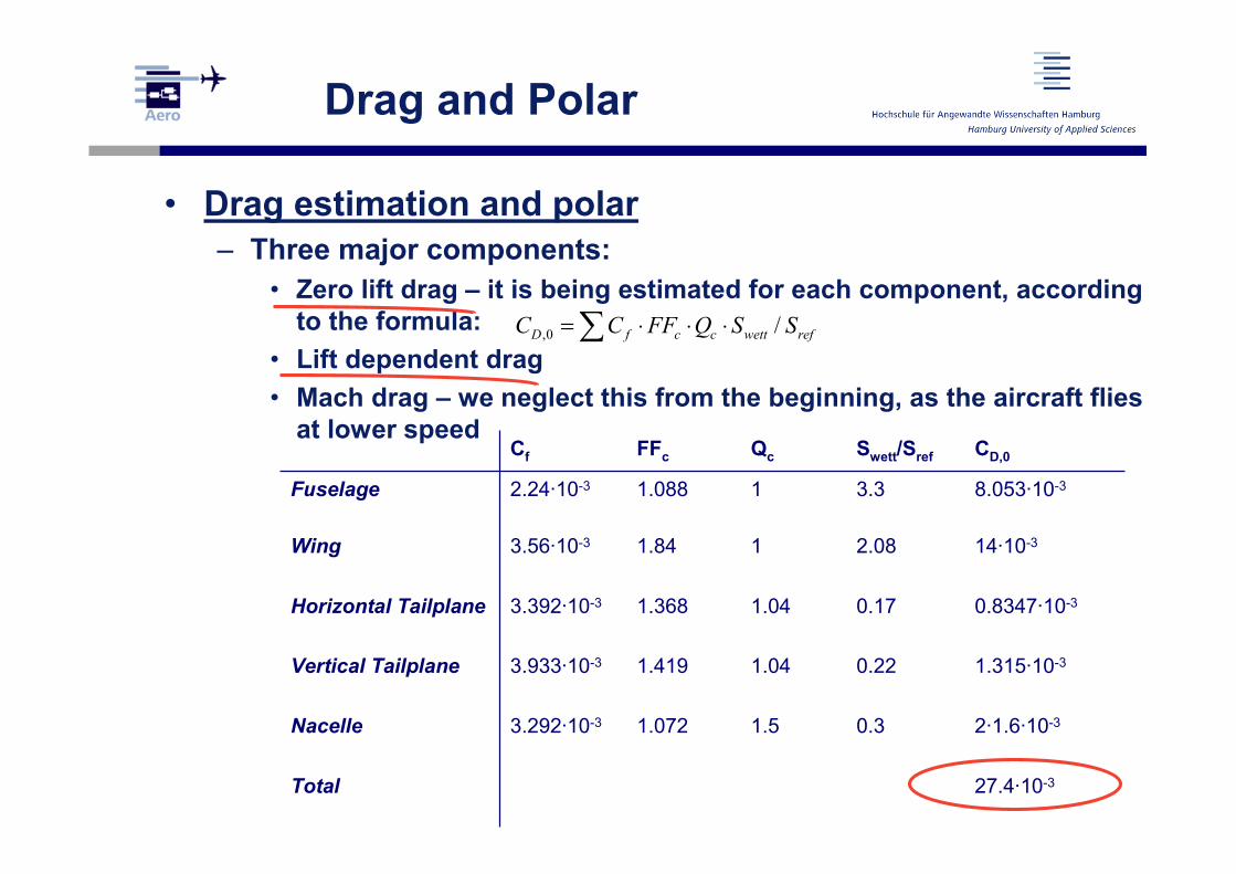
• Drag estimation and polar– Three major components:
• Zero lift drag – it is being estimated for each component, according to the formula:
• Lift dependent drag• Mach drag – we neglect this from the beginning, as the aircraft flies
at lower speed
,0 /D f c c wett refC C FF Q S S= ⋅ ⋅ ⋅∑
Drag and Polar
Cf FFc Qc Swett/Sref CD,0
Fuselage 2.24·10-3 1.088 1 3.3 8.053·10-3
Wing 3.56·10-3 1.84 1 2.08 14·10-3
Horizontal Tailplane 3.392·10-3 1.368 1.04 0.17 0.8347·10-3
Vertical Tailplane 3.933·10-3 1.419 1.04 0.22 1.315·10-3
Nacelle 3.292·10-3 1.072 1.5 0.3 2·1.6·10-3
Total 27.4·10-3

– The polar is given by
» In the preliminary sizing calculation the value e = 0.85 was used
» The resulting L/D is E = 15.8
22
,0 0.027403 0.031LD D D L
CC C C CA eπ
= + ⇔ = + ⋅⋅ ⋅
Drag and Polar

• Design evaluation– AEA method (Association of European Airliners) for
estimating the direct operating costs (DOC)
DOC Estimation
Parameters used for the estimation
Results[mil$/year]
Depreciation Service life, residual value 0.99
Interest Average interest rate, total price of the aircraft
0.73
Insurance % of aircrafts price 0.07
Fuel Price and mass fuel, no. of flights per year
2.37
Maintenance Labor and material, inflation factor
1.44
Crew No. of crew members 2.07
Fees: – Landing Maximum take-off mass, no. of flights/year, inflation factor
0.39
– Navigation Maximum take-off mass,inflation factor
0.93
– Handling Maximum payload,inflation factor
1.45

– Total DOC = the sum of the costs of each of the following elements:
CDOC=10.5 mil US$/year
DOC Estimation
DOC DEP INT INS F M C FEEC C C C C C C C= + + + + + +

Components Redesign Original DeviationFuselageLengthDiameterCabin Length
27.13 m2.77 m19.25 m
27.17 m2.57 m19.21 m
0.1%-2.0%0.1%
Wing Wing SpanWing SurfaceWing LoadingHigh Lift Device
Power PlantPower Loading
27.13 m61.3 m2
373.7 kg/m2
Double sloted flaps and slats
179.8 W/kg
27.05 m61.0 m2
373.8 kg/m2
Double sloted flaps
179.9 W/kg
0.3 %0.5 %0.0 %
-0.1 %
Horizontal TailSurface 9.7 m2 11.7 m2 -17.1 %
Vertical TailSurface 14.1 m2 12.5 m2 12.8 %
MassMaximum Take-Off MassOperating Empty Mass
22925 kg12834 kg
22800 kg12950 kg
0.5%0.9%
Summary

For more information please visit the digital library:
http://bibliothek.ProfScholz.de
and check the RRDPAE CD