RPC2 Communications Module SNMP, MIB, OID Technical Bulletin · 1OVERVIEW...
45
RPC2™ Communications Module Technical Bulletin Rack PDU SNMP OIDs
Transcript of RPC2 Communications Module SNMP, MIB, OID Technical Bulletin · 1OVERVIEW...

RPC2™ Communications Module
Technical BulletinRack PDU SNMPOIDs

Vertiv™ | RPC2 Communications Module SNMP, MIB, OID Technical Bulletin
Technical Support Site
If you encounter any installation or operational issues with your product, check the pertinent section of thismanual to see if the issue can be resolved by following outlined procedures.Visit https://www.VertivCo.com/en-us/support/ for additional assistance.
The information contained in this document is subject to change without noticeand may not be suitable for all applications. While every precaution has beentaken to ensure the accuracy and completeness of this document, Vertivassumes no responsibility and disclaims all liability for damages resulting fromuse of this information or for any errors or omissions. Refer to other localpractices or building codes as applicable for the correct methods, tools, andmaterials to be used in performing procedures not specifically described in thisdocument.
The products covered by this instruction manual are manufactured and/or soldby Vertiv This document is the property of Vertiv and contains confidential andproprietary information owned by Vertiv. Any copying, use or disclosure of itwithout the written permission of Vertiv is strictly prohibited.
Names of companies and products are trademarks or registered trademarks ofthe respective companies. Any questions regarding usage of trademark namesshould be directed to the original manufacturer.

TABLE OF CONTENTS
1 Overview 11.1 SNMP 1
1.1.1 Configuration 1
1.2 MIB File 2
2 RPC2 Configuration SNMP OID Tables 52.1 LIEBERT‐GP‐PDU-MIB::lgpPduTable 5
2.2 LIEBERT‐GP‐PDU-MIB::lgpPduPsTable 8
2.3 LIEBERT‐GP‐PDU-MIB::lgpPduRbTable 13
2.4 LIEBERT-GP-PDU-MIB::lgpPduRcpTable 19
2.5 LIEBERT‐GP‐PDU-MIB::lgpPduAuxMeasTable 24
2.6 LIEBERT‐GP‐PDU-MIB::lgpPduAuxMeasOrderTable 29
2.7 SNMP Notification Traps 29
2.8 SNMP Alarm Traps 36
I

1 OVERVIEWThis document is a supplement to the RPC2™ Communications Module User Guide and is intended to assist with usingSimple Network Management Protocol (SNMP), Management Information Base (MIB) and Object Identifiers (OIDs) withyour RPC2™ communications module and MPH2 rack PDU. For more information on using your RPC2 communicationsmodule or MPH2 rack PDU, please refer to their respective user guides.
1.1 SNMP
An SNMP manager queries an agent using User Datagram Protocol (UDP) within an IP network for specific information, andthe agent will answer the query. For example:
C:\>snmpget - v2c - cpublic - mALL -OenU 10.88.1.69.1.3.6.1.4.1.476.1.42.3.8.40.20.1.35.1.1.1.3.6.1.4.1.476.1.42.3.8.40.20.1.35.1.1 =STRING:MPHR3341C:\>
NOTE: Not all OIDs in an MIB file will return values when queried.
The SNMP agent can also send trap or notification messages.
1.1.1 Configuration
You must define on the rack PDU the devices which have access to SNMP information. You can do this from the System tabof the RPC2™ communications module.
To configure SNMP access:
1. From the System tab of the RPC2™ module user interface (UI), click SNMP-V1V2 Access.
-or-
Click SNMP-V3 Access.
2. Set the desired configuration settings and click the green Save checkmark.
To configure SNMP traps:
1. From the System tab of the RPC2 module user interface (UI), click SNMP-V1V2 Traps.
-or-
Click SNMP-V3 Traps.
2. Set the desired configuration settings and click the green Save checkmark.
NOTE: The IP address 0.0.0.0 is used to authorize a user.
NOTE: The Community string is a passphrase which needs to be configured from the management software.
1

Figure 1.1 SNMP-V1V2 Access Page
1.2 MIB File
The Management Information Base (MIB) file is a database used to manage data points. All data points are organized in adirectory tree. The MIB file organizes data points by name, but each data point name is also assigned a hierarchical numberbased on its location in the tree. The complete numerical path of a data point is that data point's object identifier (OID).
The following is an example of a MIB file:
Vertiv™ | RPC2 Communications Module SNMP, MIB, OID Technical Bulletin2

<?xml version="1.0"?>-<MIBData>-<Instances><!-- lgpPduRbEntryId.1.1 -->-<Instance valueType="Gauge" oid=".1.3.6.1.4.1.476.1.42.3.8.40.20.1.5.1.1" name="lgpPduRbEntryId.1.1">-<Value><![CDATA[1]]></Value></Instance><!-- lgpPduRbEntryId.1.2 -->-<Instance valueType="Gauge" oid=".1.3.6.1.4.1.476.1.42.3.8.40.20.1.5.1.2" name="lgpPduRbEntryId.1.2">-<Value><![CDATA[2]]></Value></Instance><!-- lgpPduRbEntryUsrLabel.1.1 -->-<Instance valueType="OctetString" oid=".1.3.6.1.4.1.476.1.42.3.8.40.20.1.8.1.1" name="lgpPduRbEntryUsrLabel.1.1">-<Value><![CDATA[Branch A]]></Value></Instance><!-- lgpPduRbEntryUsrLabel.1.2 -->-<Instance valueType="OctetString" oid=".1.3.6.1.4.1.476.1.42.3.8.40.20.1.8.1.2" name="lgpPduRbEntryUsrLabel.1.2">-<Value><![CDATA[Branch B]]></Value></Instance><!-- lgpPduRbEntrySysAssignLabel.1.1 -->-<Instance valueType="OctetString" oid=".1.3.6.1.4.1.476.1.42.3.8.40.20.1.20.1.1"name="lgpPduRbEntrySysAssignLabel.1.1">-<Value><![CDATA[1-A]]></Value></Instance><!-- lgpPduRbEntrySysAssignLabel.1.2 -->-<Instance valueType="OctetString" oid=".1.3.6.1.4.1.476.1.42.3.8.40.20.1.20.1.2"name="lgpPduRbEntrySysAssignLabel.1.2">-<Value><![CDATA[1-B]]></Value></Instance><!-- lgpPduRbEntryPositionRelative.1.1 -->-<Instance valueType="Gauge" oid=".1.3.6.1.4.1.476.1.42.3.8.40.20.1.25.1.1" name="lgpPduRbEntryPositionRelative.1.1">-<Value><![CDATA[1]]></Value></Instance><!-- lgpPduRbEntryPositionRelative.1.2 -->-<Instance valueType="Gauge" oid=".1.3.6.1.4.1.476.1.42.3.8.40.20.1.25.1.2" name="lgpPduRbEntryPositionRelative.1.2">-<Value><![CDATA[2]]></Value></Instance><!-- lgpPduRbEntrySerialNum.1.1 -->-<Instance valueType="OctetString" oid=".1.3.6.1.4.1.476.1.42.3.8.40.20.1.30.1.1" name="lgpPduRbEntrySerialNum.1.1">-<Value><![CDATA[418321G3-A]]></Value></Instance><!-- lgpPduRbEntrySerialNum.1.2 -->-<Instance valueType="OctetString" oid=".1.3.6.1.4.1.476.1.42.3.8.40.20.1.30.1.2" name="lgpPduRbEntrySerialNum.1.2">-<Value><![CDATA[418321G3-B]]>
1 Overview 3

</Value></Instance></Instances></MIBData>
Within the Vertiv™ MIB Archive you’ll find the following three enterprise-specific MIB files:
• LIEBERT_GP_PDU.MIB
• LIEBERT_GP_REGISTRATION.MIB
• LIEBERT_GP_SYSTEM.MIB
These files can be downloaded from https://www.vertivco.com/en-us/support/software-download/it-management/mph2-managed-rack-pdu-software-downloads/.
Vertiv™ | RPC2 Communications Module SNMP, MIB, OID Technical Bulletin4

2 RPC2 CONFIGURATION SNMP OID TABLESThe following tables display information about the OIDs of the Liebert_GP_PDU.MIB.
NOTE: The following OIDs are not completely defined in that a set of row indices need to be appended in order toindex into the correct row of the table. For example, lgpPduRcpEntryUsrLabel would give an OID of.1.3.6.1.4.1.476.1.42.3.8.50.20.1.10.X.Y.Z, where X=PDU number in an array, Y=Branch number, and Z=Receptaclenumber. The maximum dimension and range of the row indices are model and OID specific and can be determinedthrough MIB browser analysis.
2.1 LIEBERT‐GP‐PDU-MIB::lgpPduTable
OID / NAME
SYNTAX ACCESS DESCRIPTION DEFAULT UNITS RANGE COMMENT
1.3.6.1.4.1.476.1.42.3.8.10.5lgpPduGrpSysStatus.0
Gauge32 RO
Bit‐wise logical OR of all of the 'lgpPduEntrySysStatus' columns in the'lgpPduTable' which represents the combined statuses of all PDUs forthis agent. Note the bit position is given parenthetically next to theoperational state in the description below. The bit position is big‐endian(least significant digit is the right-most digit). The state is present in thePDUwhen the bit is on (value =1). The value is a logical OR of all of thefollowing potential states of each PDU in the cluster.
normalOperation(1): One or more PDUs in the cluster are operatingnormally with no active warnings or alarms.
startUp(2): One or more PDUs are in the startup state (initializing).Control andmonitoring operationsmay be inhibited or unavailablewhile the PDU is in this state.
unknownNoSupport(4): The state of one or more PDUs are not knownat this time or there is no support for this piece of information from 1 ormore PDUs in the cluster/group.
normalWithWarning(8): One or more PDUs are operating normally withone or more active warnings. Appropriate personnel should investigatethe warning(s) as soon as possible and take appropriate action.
normalWithAlarm(16): One or more PDUs are operating normally withone or more active alarms. Appropriate personnel should investigatethe alarm(s) as soon as possible and take appropriate action.
abnormalOperation(32): One or more PDUs are operating abnormally.There is a failure within the system that is unexpected under normaloperating conditions. Appropriate personnel should investigate thecause as soon as possible. The normal functioning of the system islikely inhibited
unknownCommFailure(64): The state will clear automatically when thePDU (s) are fully initialized and ready to accept.
startUp(2)
.1.3.6.1.4.1.476.1.42.3.8.19lgpPduTableCount.0
Gauge32RO
Number of PDUs beingmonitored by this agent. This is the number ofentries in the lgpPduTable.
.1.3.6.1.4.1.476.1.42.3.8.20.1.5lgpPduEntryId.1
Gauge32 ROInternal index representing a unique identifier for each PDUrepresented by this agent. The value is assigned by the agent at thetime of discovery.
.1.3.6.1.4.1.476.1.42.3.8.20.1.10
Table 2.1 Liebert-GP-PDU-MIB::IgpPduTable
5

OID / NAME
SYNTAX ACCESS DESCRIPTION DEFAULT UNITS RANGE COMMENT
lgpPduEntryUsrLabel.1
String RO User assigned label representing the PDU.<MPH> or<MPH2> or<MPX>
0-48characters
Defaultassignmentdepends upondevicediscovered atpower up. Theallowedcharactersincludealphanumeric,space, and~!#$_+`-={}|[]\:; '?,./%^&*()@
.1.3.6.1.4.1.476.1.42.3.8.20.1.15lgpPduEntrySysAssignLabel.1
String RO System assigned identifier representing the PDU. 1
The value isindependent ofany userassigned labelor tag.
.1.3.6.1.4.1.476.1.42.3.8.20.1.20lgpPduEntryPositionRelative.1
Gauge32 RO Indicates the PDU's relative position within the array. 1 1-4
.1.3.6.1.4.1.476.1.42.3.8.20.1.25lgpPduEntrySysStatus.1
Gauge32 RO
Bit-field of the various operational states of the PDU. The value is alogical OR of all of the following potential states of the PDU. Note thebit position is given parenthetically next to the operational state in thedescription below. The bit position is assumed to be a big‐endianformat (least significant digit is the right-most digit).
The state is present in the PDUwhen the bit is on (value=1).
normalOperation(1): The PDU is operating normally with no activewarnings or alarms.
startUp(2) - The PDU is in the startup state The state is present in thePDUwhen the bit is on (value=1).
normalOperation(1): The PDU is operating normally with no activewarnings or alarms.
startUp(2) - The PDU is in the startup state (initializing). Control andmonitoring operationsmay be inhibited or unavailable while the PDU isin this state. This state will clear automatically when the PDU(s) arefully initialized and ready to accept control andmonitoring commands.
normalWithWarning(8): The PDU is operating normally with one ormore active warnings. Appropriate personnel should investigate thewarning(s) as soon as possible and take appropriate action.
normalWithAlarm(16): The PDU is operating normally with one or moreactive alarms. Appropriate personnel should investigate the alarm(s)as soon as possible and take appropriate action.
Table 2.1 Liebert-GP-PDU-MIB::IgpPduTable (continued)
Vertiv™ | RPC2 Communications Module SNMP, MIB, OID Technical Bulletin6

OID / NAME
SYNTAX ACCESS DESCRIPTION DEFAULT UNITS RANGE COMMENT
abnormalOperation(32): The PDU is operating abnormally. That isthere is some failure within the system that is unexpected undernormal operating conditions. Appropriate personnel should investigatethe cause as soon as possible. The normal functioning of the system islikely inhibited.
.1.3.6.1.4.1.476.1.42.3.8.20.1.35lgpPduEntryUsrTag1.1
String RW
A configuration parameter to set user assigned tag for the PDU. Thisvalue may be useful for enduser grouping or asset tracking purposes.The value for this tag does not need to be unique for this unit or acrossother units.
<empty>0-48characters
The allowedcharactersincludealphanumeric,space, and~!#$_+`-={}|[]\\:; '?,.\/%^&*()@
.1.3.6.1.4.1.476.1.42.3.8.20.1.40lgpPduEntryUsrTag2.1
String RW A configuration parameter to set user assigned tag <empty>0-48characters
The allowedcharactersincludealphanumeric,space, and~!#$_+`-={}|[]\\:; '?,.\/%^&*()@
.1.3.6.1.4.1.476.1.42.3.8.20.1.45lgpPduEntrySerialNumber.1
String ROSerial number for this RPC2 module assigned at time of manufactureand is globally unique with respect to all RPC2 modules.
The agent serialnumbers foreachmemberof the array isreported.
.1.3.6.1.4.1.476.1.42.3.8.20.1.50lgpPduEntryRbCount.1
Gauge32 RO Number of receptacle branches within this PDU. 1-7Maximumseven branchesare supported.
.1.3.6.1.4.1.476.1.42.3.8.20.1.55lgpPduEntrySWOverCurrentProtection.1
Integer RW
A configuration parameter to enable or disable the Software OverCurrent Protection (SWOCP) feature to prevent unused receptaclesfrom turning on when the 'PDUOver Current Warning' or 'PDUOverCurrent Alarm' threshold is violated. Only admin users shall have theauthorization to unlock such receptacles. If the feature is enabled, incase of PDUOver Current Warning or Alarm condition, the followingaction will be taken on the receptacles:
Locked & Off: No change.
Locked & On: No change.
Unlocked & Off: Receptacle shall be locked.
Unlocked & On: If the receptacle is drawing current, then no change. Ifthat receptacle is not drawing current, then turn it off and lock it.
No action will be taken if the feature is disabled.
disabled(0)
0-1
Only applicableto PDUs havingreceptaclemeasurementand control.
Table 2.1 Liebert-GP-PDU-MIB::IgpPduTable (continued)
2 RPC2 Configuration SNMP OID Tables 7

2.2 LIEBERT‐GP‐PDU-MIB::lgpPduPsTable
OID / NAME
SYNTAX ACCESS DESCRIPTION DEFAULT UNITS RANGE COMMENT
.1.3.6.1.4.1.476.1.42.3.8.30.19lgpPduPsTableCount.0
Gauge32 RONumber of power source in the IgpPduPsTable.
.1.3.6.1.4.1.476.1.42.3.8.30.20.1.10lgpPduPsEntryId.1.1
Gauge32RO
This is a unique entry id representing a givenPDUpower source for the PDU.
1-3
.1.3.6.1.4.1.476.1.42.3.8.30.20.1.15lgpPduPsEntrySysAssignLabel.1.1
String RO
System assigned identifier for this powersource. The value is independent of any userassigned label or tag. The exact format ofthis label is system dependent and is subjectto change; therefore, it should not bereferenced for programmatic use.
<x> Format is x=PDU {1-4}
.1.3.6.1.4.1.476.1.42.3.8.30.20.1.20gpPduPsEntryModel.1.1
String ROModel number assigned at the time ofmanufacture.
This string is displayed on the PDU'snameplate barcode.
.1.3.6.1.4.1.476.1.42.3.8.30.20.1.25lgpPduPsEntryWiringType.1.1
Integer RW
Enumerations that describe the number ofpoles/phase and wires of the PDUpowersource.
not-specified (0): The type has not beenspecified or configure this object to specifythe physical wiring type.
single-phase-3-wire L1-N-PE (1) single-phaseinput with three wires (1P3W).
two-phase-3-wire-L1-L2-PE (2): Two-phaseinput with three wires (2P3W).
three-phase-4-wire-L1-L2-L3-PE (3): Three-phase input with four wires (2P4W).
three-phase-5-wire L1-L2-L3-N-PE (4):Three-phase input with five wires (3P4W).
two-phase-4-wire-L1-L2-N-PE (5): Two-phaseinput with four wires (2P4W).
0 0-5
Some ULListed 3P4W PDUsmay beequipped with a 3P5W plug type, e.g. L21-30P, where the neutral is unused. It is notrecommended this object be written.
.1.3.6.1.4.1.476.1.42.3.8.30.20.1.30lgpPduPsEntryEpInputRated.1.1
Gauge32 RO
Rated phase or line voltage, either line-to-neutral or line-to-line depending upon thePDU's power source assigned at the time ofmanufacture.
VoltsEither the nominal or maximum value ofthe range is reported, whichever is greater.
.1.3.6.1.4.1.476.1.42.3.8.30.20.1.35lgpPduPsEntryEcInputRated.1.1
Table 2.2 Liebert-GP-PDU-MIB::IgpPduPs Table
Vertiv™ | RPC2 Communications Module SNMP, MIB, OID Technical Bulletin8

OID / NAME
SYNTAX ACCESS DESCRIPTION DEFAULT UNITS RANGE COMMENT
Gauge32 RORated input line current, depending upon thePDU's power source, assigned at the time ofmanufacture.
0.1 RMSAmperes
For UL-listed PDUs, the value is derated to80% of actual plug/cord rating.
.1.3.6.1.4.1.476.1.42.3.8.30.20.1.40lgpPduPsEntryFreqRated.1.1
Gauge32 RORated line frequency for this PDUassignedat the time of manufacture.
50 or 60Hertz(Hz)
50 or 60Irrespective of region, all PDUs canoperate at either 50Hz or 60Hz.
.1.3.6.1.4.1.476.1.42.3.8.30.20.1.50lgpPduPsEntryEnergyAccum.1.1
Gauge32 RW
Total accumulated energy of this PDU sincethe last energy reset. Writing a value of zerocauses the accumulated energy to be reset.Writing a nonzero value is invalid and shallresult in a write error and the total energyvalue remains unchanged.
0
0.1kiloWatt-hr (kW-h)
If the energy has not been reset and hasnot overflowed the 32-bit value, then this isthe total energy since installation. Thisvalue persists across boot and power cycleevents.
.1.3.6.1.4.1.476.1.42.3.8.30.20.1.55lgpPduPsEntrySerialNum.1.1
String ROSerial number for this PDUassigned at timeof manufacture and is globally unique withrespect to all PDUunits.
This string is displayed on the PDU'snameplate barcode.
.1.3.6.1.4.1.476.1.42.3.8.30.20.1.60lgpPduPsEntryFirmwareVersion.1.1
String RO Version of firmware installed on the device.This firmware version is unique comparedto the agent's firmware version.
.1.3.6.1.4.1.476.1.42.3.8.30.20.1.65lgpPduPsEntryPwrTotal.1.1
Gauge32 ROTotal input power calculated from thesummation of phase currents of this PDU.
Watts
.1.3.6.1.4.1.476.1.42.3.8.30.20.1.70lgpPduPsEntryEcNeutral.1.1
Gauge32 RONeutral current calculated from thesummation of all phases of this PDU.
0.1 RMSAmperes
Supported for three-phase PDUs only.
.1.3.6.1.4.1.476.1.42.3.8.30.20.1.75lgpPduPsEntryEcNeutralThrshldOvrWarn.1.1
Gauge32 RW
A configuration parameter to set thethreshold at which an overcurrent warning isactivated. If the measured line current isequal to or over this percentage of the fullscale rated value.IgpPduPsEntryEclnputRated, an overcurrentwarning is activated.
40 % 0-100Must be less thanIgpPduPsEntryEcNeauralThrshldOvrAlarm
.1.3.6.1.4.1.476.1.42.3.8.30.20.1.80lgpPduPsEntryEcNeutralThrshldOvrAlarm.1.1
Gauge32 RW
A configuration parameter to set thethreshold at which an overcurrent alarm isactivated. If the measured line current isequal to or over this percentage of the fullscale rated value.IgpPduPsEntryEclnputRated, an overcurrentalarm is activated.
45 % 0-100Must be greater thanIgpPduPsEntryEcNeutralThrshldOvrWarn
Table 2.2 Liebert-GP-PDU-MIB::IgpPduPs Table (continued)
2 RPC2 Configuration SNMP OID Tables 9

OID / NAME
SYNTAX ACCESS DESCRIPTION DEFAULT UNITS RANGE COMMENT
.1.3.6.1.4.1.476.1.42.3.8.30.20.1.85lgpPduPsEntryUnbalancedLoadThrshldAlarm.1.1
Gauge32 RW
A configuration parameter to set themaximum acceptable percentage of"Unbalanced Load" between any two phases.This setting shall trigger an alarm when the %difference between any two phases isgreater than this value. If this value is 0%then the alarm shall be deactivated.
0 %
.1.3.6.1.4.1.476.1.42.3.8.30.20.1.90lgpPduPsEntryApTotal.1.1
Gauge32 ROThe summation of apparent powerconsumed by all the phases.
RMSVolts-Amperes(VA)
.1.3.6.1.4.1.476.1.42.3.8.30.20.1.95lgpPduPsEntryPfTotal.1.1
Integer ROPower Factor of all the phasesmeasured asthe average of the phases' ratio of real powerto apparent power.
0.000.00-1.00
1.3.6.1.4.1.476.1.42.3.8.30.40.1.10lgpPduPsLineEntryId.1.1.1
Gauge32 RO Unique identifier for the PDU's power source. 1-3
.1.3.6.1.4.1.476.1.42.3.8.30.40.1.15lgpPduPsLineEntryLine.1.1.1
Integer RO
Enumerations that describe the line/phase ofthe PDU's power source that themeasurement represents for allmeasurements in a given rowof the table.Note that this alwaysmatches theIgpPduPsLineEntryIndex of the same row inthe table. The line/phases are as follows:
phase 1(1): Line 1-N or Line 1-2.
phase2(2): Line 2-N or Line 2-3.
phase3(3): Line 3-N or Line3-1.
1-3
.1.3.6.1.4.1.476.1.42.3.8.30.40.1.19lgpPduPsLineEntryEpLNTenths.1.1.1
Gauge32 ROThe voltage applied to the line-to neutralphase measured in tenths of volts RMS (RootMeansSquared).
0.1 RMSVolts
.1.3.6.1.4.1.476.1.42.3.8.30.40.1.20lgpPduPsLineEntryEpLN.1.1.1
Gauge32 ROThe voltage applied to the line-to-neutralphase measured in volts RMS (Root MeanSquared).
RMSVolts
.1.3.6.1.4.1.476.1.42.3.8.30.40.1.21lgpPduPsLineEntryEc.1.1.1
Gauge32 ROCurrent drawn through the phrase/linemeasured in tenths of Amperes RMS (Root
0.1 RMSAmperes
Table 2.2 Liebert-GP-PDU-MIB::IgpPduPs Table (continued)
Vertiv™ | RPC2 Communications Module SNMP, MIB, OID Technical Bulletin10

OID / NAME
SYNTAX ACCESS DESCRIPTION DEFAULT UNITS RANGE COMMENT
Mean Squared).
.1.3.6.1.4.1.476.1.42.3.8.30.40.1.22lgpPduPsLineEntryEcHundredths.1.1.1
Gauge32 ROCurrent drawn through the phrase/linemeasured in hundredths of Amperes RMS(Root Mean Squared).
0.01RMSAmperes
.1.3.6.1.4.1.476.1.42.3.8.30.40.1.35lgpPduPsLineEntryEcThrshldUndrAlarm.1.1.1
Gauge32 RW
A configuration parameter to set thethreshold at which an undercurrent alarm isactivated. If the measured line current isequal to or below this percentage of the fullscale rated value,IgpPduPsEntryEclnputRated, anundercurrent alarm is activated.
%
Must be less thanIgpPduPsEntryEcThrshldOverWarnand less thanIgpPduPsEntryEcThrshldOverAlarm
.1.3.6.1.4.1.476.1.42.3.8.30.40.1.36lgpPduPsLineEntryEcThrshldOvrWarn.1.1.1
Gauge32 RW
A configuration parameter to set thethreshold at which an overcurrent warning isactivated. If the measured line current isequal to or over this percentage of the fullscale rated value,IgpPduPsEntryEclnputRated, an overcurrentwarning is activated.
% 100
Must be greater thanIgpPduPsEntryEcThrshldUnderAlarmand less thanIgpPduPsEntryEcThrshldOverAlarm
.1.3.6.1.4.1.476.1.42.3.8.30.40.1.37lgpPduPsLineEntryEcThrshldOvrAlarm.1.1.1
Gauge32 RW
A configuration parameter to set thethreshold at which an overcurrent alarm isactivated. If the measured line current isequal to or over this percentage of the fullscale rated value.IgpPduPsEntryEclnputRated, an overcurrentalarm is activated.
% 0-100
Must be greater thanIgpPduPsEntryEcThrshldUnderAlarmand greater thanIgpPduEntryEcThrshldOverWarn
.1.3.6.1.4.1.476.1.42.3.8.30.40.1.38lgpPduPsLineEntryEcAvailBeforeAlarm.1.1.1
Gauge32 ROThe amount that the line current mayincrease from its present value before anover current alarm occurs.
0.1 RMSAmperes
.1.3.6.1.4.1.476.1.42.3.8.30.40.1.39lgpPduPsLineEntryEcUsedBeforeAlarm.1.1.1
Gauge32 ROThe percent of line current utilization relativeto the over current alarm threshold.
0.1%0.0-100.0
.
.1.3.6.1.4.1.476.1.42.3.8.30.40.1.60lgpPduPsLineEntryEpLL.1.1.1
Gauge32 ROThe voltage applied to the line-to-line phasemeasured in volts RMS (Root MeanSquared).
RMS
Volts
.1.3.6.1.4.1.476.1.42.3.8.30.40.1.61lgpPduPsLineEntryEpLLTenths.1.1.1
Gauge32 RO The voltage applied to the line-to-line phase 0.1 RMS
Table 2.2 Liebert-GP-PDU-MIB::IgpPduPs Table (continued)
2 RPC2 Configuration SNMP OID Tables 11

OID / NAME
SYNTAX ACCESS DESCRIPTION DEFAULT UNITS RANGE COMMENT
measured in tenth volts RMS (Root MeanSquared).
Volts
42.3.8.30.40.1.62lgpPduPsLineEntryEcAvailBeforeAlarmHundredths.1.1.1
Gauge32 ROThe amount that the line current mayincrease from its present value before anover current alarm occurs.
0.01RMSAmperes
.1.3.6.1.4.1.476.1.42.3.8.30.40.1.63lgpPduPsLineEntryPwrLN.1.1.1
Gauge32 ROReal power consumed by the line-to-neutralphase.
Watts
.1.3.6.1.4.1.476.1.42.3.8.30.40.1.64lgpPduPsLineEntryPwrLL.1.1.1
Gauge32RO
Real power consumed by the line-to-linephase.
Watts
.1.3.6.1.4.1.476.1.42.3.8.30.40.1.65lgpPduPsLineEntryApLN.1.1.1
Gauge32 ROApparent power consumed by the line-to-neutral phase.
RMSVolts-Amperes(VA)
.1.3.6.1.4.1.476.1.42.3.8.30.40.1.66lgpPduPsLineEntryApLL.1.1.1
Gauge32 ROApparent power consumed by the line-to-linephase.
RMSVolts-Amperes(VA)
.1.3.6.1.4.1.476.1.42.3.8.30.40.1.67lgpPduPsLineEntryPfLN.1.1.1
Integer ROPower factor of the line-to-neutral phasemeasured as the ratio of real power toapparent power.
0.000.00-1.00
.1.3.6.1.4.1.476.1.42.3.8.30.40.1.68lgpPduPsLineEntryPfLL.1.1.1
Integer ROPower factor of the line-to-line phasemeasured as the ratio of real power toapparent power.
0.000.00-1.00
Table 2.2 Liebert-GP-PDU-MIB::IgpPduPs Table (continued)
Vertiv™ | RPC2 Communications Module SNMP, MIB, OID Technical Bulletin12

2.3 LIEBERT‐GP‐PDU-MIB::lgpPduRbTable
OID / NAME
SYNTAX ACCESS DESCRIPTION DEFAULT UNIT RANGE COMMENT
.1.3.6.1.4.1.476.1.42.3.8.40.19lgpPduRbTableCount.0
Gauge32 RONumber of receptacle branches in thelgpPduRbTable.
1-7
.1.3.6.1.4.1.476.1.42.3.8.40.20.1.5lgpPduRbEntryId.1.1
Gauge32 RO
A unique id assigned at device discoveryrepresenting the receptacle branch withinthe collection of branches beingmonitored by this agent. The uniquenessof this id is within the scope of PDUs beingmanaged by a single agent.
.1.3.6.1.4.1.476.1.42.3.8.40.20.1.8lgpPduRbEntryUsrLabel.1.1
String RWA configuration parameter to set userassigned label representing thereceptacle branch.
<Branch x>,wherex=A-G
0-48characters
The allowed characters includealphanumeric, space, and ~!#$_+`-={}|[]\\:; '?,.\/%^&*()@
.1.3.6.1.4.1.476.1.42.3.8.40.20.1.20lgpPduRbEntrySysAssignLabel.1.1
String RO
System assigned identifier for thisreceptacle branch. The value isindependent of any user assigned label ortag. The exact format of this label issystem dependent and is subject tochange; therefore, it should not bereferenced for programmatic use.
<x-y>
x=PDU {1-4},y=Branch{AG}
For MPXBRM, the Branch alphacharacter maps to the numericalid as follows: {A thru G} -> {1 thru7}
.1.3.6.1.4.1.476.1.42.3.8.40.20.1.25lgpPduRbEntryPositionRelative.1.1
Gauge32 ROIndicates the relative position of thereceptacle branch within the PDU.
1-7
.1.3.6.1.4.1.476.1.42.3.8.40.20.1.30lgpPduRbEntrySerialNum.1.1
String RO
A globally unique serial number for thisreceptacle branch. This number isassigned to the branch at the time ofmanufacture and cannot be modified.
MPXBRM are hot-swappablereceptacle branches and haveunique serial numbers.
.1.3.6.1.4.1.476.1.42.3.8.40.20.1.35lgpPduRbEntryModel.1.1
String ROModel number of receptacle branchdevice assigned at the time ofmanufacture.
.1.3.6.1.4.1.476.1.42.3.8.40.20.1.40lgpPduRbEntryFirmwareVersion.1.1
StringRO
Version of firmware installed on thedevice’s receptacle branch hardware.
.1.3.6.1.4.1.476.1.42.3.8.40.20.1.41lgpPduRbEntryUsrTag1.1.1
Table 2.3 Liebert GP-PDU-MIB::IgpPdRb Table
2 RPC2 Configuration SNMP OID Tables 13

OID / NAME
SYNTAX ACCESS DESCRIPTION DEFAULT UNIT RANGE COMMENT
String RW
A configuration parameter to set userassigned tag for the receptacle branch.This value may be useful for end‐usergrouping or asset tracking purposes. Thevalue for this tag does not need to beunique for this unit or across other units.
<empty>0-48characters
The allowed characters includealphanumeric, space, and ~!#$_+`-={}|[]\\:; '?,.\/%^&*()@
.1.3.6.1.4.1.476.1.42.3.8.40.20.1.42lgpPduRbEntryUsrTag2.1.1
String RW
A configuration parameter to set userassigned tag for the receptacle branch.This value may be useful for end‐usergrouping or asset tracking purposes. Thevalue for this tag does not need to beunique for this unit or across other units.
0-48characters
The allowed characters includealphanumeric, space, and ~!#$_+`-={}|[]\\:; '?,.\/%^&*()@
.1.3.6.1.4.1.476.1.42.3.8.40.20.1.45lgpPduRbEntryReceptacleType.1.1
Integer RO
Enumerations that describe the type ofreceptacles installed on this receptaclebranch.
not-specified(0): If this value is returned,either the receptacle type has not beenspecified/configured or the agentmonitoring this PDUdoes not have aSNMP enumeration defined to the type.
nema-5-20R-20-Amp(1)
iec-C13‐-sheet-F-10-Amp (2)
iec-C19-sheet-J-16-Amp(3)
iec-C13-sheet-F-10-Amp-and-iec-C19-sheet-J-16-Amp(4)
nema-5-20R-20-Amp‐and-iec-C13‐sheet- F-10-Amp(5)
nema-5-20R-20-Amp‐and-iec-C19‐sheet-J- 16-Amp(6)
cee-7-type-E-schuko(7)
0 0-7
.1.3.6.1.4.1.476.1.42.3.8.40.20.1.50lgpPduRbEntryCapabilities.1.1
Integer RO
Enumerations that describe the supportedreceptacle branch performancecapabilities.
not-specified(0)
no-optional-capabilities(1): Does notsupport
receptacle measurement and control.
measurement-only(2): Supportsreceptacle measurements.
measurement-and-control(3): Supportseceptacle measurements and receptaclecontrol.
control-only (4): Supports receptaclecontrol.
0 0-6
All PDUs support inputmeasurements. First generationMPHmodels do not supportvoltage and power-relatedmeasurements at the branches.
Table 2.3 Liebert GP-PDU-MIB::IgpPdRb Table (continued)
Vertiv™ | RPC2 Communications Module SNMP, MIB, OID Technical Bulletin14

OID / NAME
SYNTAX ACCESS DESCRIPTION DEFAULT UNIT RANGE COMMENT
current-measurement-only(5): Supportscurrent measurements only.
current‐measurement-and-control(6):supports current measurements.
.1.3.6.1.4.1.476.1.42.3.8.40.20.1.55lgpPduRbEntryLineSource.1.1
Integer RO
Enumerations that describe the PDU’svoltage source phasing supplying powerto this receptacle branch.
not-specified (0): The line sourcesupplying power to the load for thisreceptacle branch has not been specifiedor configured.
line-1-N(1): The load for this receptaclebranch is supplied by a line-to-neutralconfiguration.
line-2-N(2): The load for this receptaclebranch is supplied by a line-to-neutralconfiguration. (line 2 to neutral).
line-3-N (3): The load for this receptaclebranch is supplied by a line-to-neutralconfiguration.
line-1-line-2(4): The load for thisreceptacle branch is supplied by a line-to-line configuration.
line-2-line-3(5): The load for thisreceptacle branch is supplied by a line-to-line configuration.
line-3‐line-1(6): The load for thisreceptacle branch is supplied by a line‐to-line configuration.
line-1-line-2-and-line-1‐neutral(7): Theload for this mixed receptacle branch issupplied by a line-to-line and line-to-neutral configuration.
line-2-line-3-and-line-2-neutral(8): Theload for this mixed receptacle branch issupplied by a line-to-line and line-to-neutral configuration.
line-3-line-1-and-line-3-neutral(9): Theload for this mixed receptacle branch issupplied by a line-to-line and line-to-neutral configuration.
1.3.6.1.4.1.476.1.42.3.8.40.20.1.60lgpPduRbEntryRcpCount.1.1
Gauge32 ROThe number of receptacles on thisreceptacle branch.
.1.3.6.1.4.1.476.1.42.3.8.40.20.1.70lgpPduRbEntryEpRated.1.1
Gauge32 RORated phase or line voltage, either line-to-neutral or line-to-line, for the receptaclebranch assigned at the time of
0.1 RMSVolts
Either the nominal or maximumvalue of the range is reported,whichever is greater.
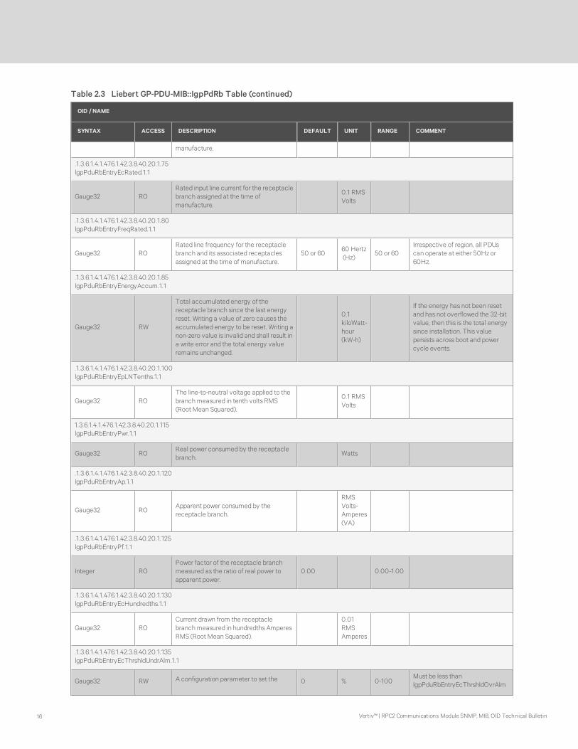
Table 2.3 Liebert GP-PDU-MIB::IgpPdRb Table (continued)
2 RPC2 Configuration SNMP OID Tables 15
OID / NAME
SYNTAX ACCESS DESCRIPTION DEFAULT UNIT RANGE COMMENT
manufacture.
.1.3.6.1.4.1.476.1.42.3.8.40.20.1.75lgpPduRbEntryEcRated.1.1
Gauge32 RORated input line current for the receptaclebranch assigned at the time ofmanufacture.
0.1 RMSVolts
.1.3.6.1.4.1.476.1.42.3.8.40.20.1.80lgpPduRbEntryFreqRated.1.1
Gauge32 RORated line frequency for the receptaclebranch and its associated receptaclesassigned at the time of manufacture.
50 or 6060 Hertz(Hz)
50 or 60Irrespective of region, all PDUscan operate at either 50Hz or60Hz.
.1.3.6.1.4.1.476.1.42.3.8.40.20.1.85lgpPduRbEntryEnergyAccum.1.1
Gauge32 RW
Total accumulated energy of thereceptacle branch since the last energyreset. Writing a value of zero causes theaccumulated energy to be reset. Writing anon-zero value is invalid and shall result ina write error and the total energy valueremains unchanged.
0.1kiloWatt-hour(kW-h)
If the energy has not been resetand has not overflowed the 32-bitvalue, then this is the total energysince installation. This valuepersists across boot and powercycle events.
.1.3.6.1.4.1.476.1.42.3.8.40.20.1.100lgpPduRbEntryEpLNTenths.1.1
Gauge32 ROThe line-to-neutral voltage applied to thebranchmeasured in tenth volts RMS(Root Mean Squared).
0.1 RMSVolts
1.3.6.1.4.1.476.1.42.3.8.40.20.1.115lgpPduRbEntryPwr.1.1
Gauge32 ROReal power consumed by the receptaclebranch.
Watts
.1.3.6.1.4.1.476.1.42.3.8.40.20.1.120lgpPduRbEntryAp.1.1
Gauge32 ROApparent power consumed by thereceptacle branch.
RMSVolts-Amperes(VA)
.1.3.6.1.4.1.476.1.42.3.8.40.20.1.125lgpPduRbEntryPf.1.1
Integer ROPower factor of the receptacle branchmeasured as the ratio of real power toapparent power.
0.00 0.00-1.00
.1.3.6.1.4.1.476.1.42.3.8.40.20.1.130lgpPduRbEntryEcHundredths.1.1
Gauge32 ROCurrent drawn from the receptaclebranchmeasured in hundredths AmperesRMS (Root Mean Squared).
0.01RMSAmperes
.1.3.6.1.4.1.476.1.42.3.8.40.20.1.135lgpPduRbEntryEcThrshldUndrAlm.1.1
Gauge32 RW A configuration parameter to set the 0 % 0-100Must be less thanlgpPduRbEntryEcThrshldOvrAlm
Table 2.3 Liebert GP-PDU-MIB::IgpPdRb Table (continued)
Vertiv™ | RPC2 Communications Module SNMP, MIB, OID Technical Bulletin16

OID / NAME
SYNTAX ACCESS DESCRIPTION DEFAULT UNIT RANGE COMMENT
threshold at which an undercurrent alarmis activated. If the measured receptaclebranch current is equal to or below thispercentage of the full scale rated value,lgpPduRbEntryEcRated, an undercurrentalarm is activated.
and less thanlgpPduRbEntryEcThrshldOvrWarn
.1.3.6.1.4.1.476.1.42.3.8.40.20.1.140lgpPduRbEntryEcThrshldOvrWarn.1.1
Gauge32 RW
A configuration parameter to set thethreshold at which an overcurrent warningis activated. If the measured receptaclebranch current is equal to or over thispercentage of the full scale rated value,lgpPduRbEntryEcRated, an overcurrentwarning is activated.
90 % 0-100
Must be less thanlgpPduRbEntryEcThrshldOvrAlmand greater thanlgpPduRbEntryEcThrshldUndrAlm
.1.3.6.1.4.1.476.1.42.3.8.40.20.1.145lgpPduRbEntryEcThrshldOvrAlm.1.1
Gauge32 RW
A configuration parameter to set thethreshold at which an overcurrent alarm isactivated. If the measured receptaclebranch current is equal to or over thispercentage of the full scale rated value,lgpPduRbEntryEcRated, an over currentalarm is activated.
95 % 0-100
Must be greater thanlgpPduRbEntryEcThrshldUndrAlmand greater thanlgpPduRbEntryEcThrshldOvrWarn
.1.3.6.1.4.1.476.1.42.3.8.40.20.1.150lgpPduRbEntryEcAvailBeforeAlarmHundredths.1.1
Gauge32 RO
The amount that the receptacle branchcurrent may increase from its presentvalue before an overcurrent alarmoccurs.
0.01RMSAmperes
.1.3.6.1.4.1.476.1.42.3.8.40.20.1.160lgpPduRbEntryEcUsedBeforeAlarm.1.1
Gauge32 ROThe percent of receptacle branch currentutilization relative to the overcurrentalarm threshold.
0.1% 0.0-100.0
.1.3.6.1.4.1.476.1.42.3.8.40.20.1.170lgpPduRbEntryEpLLTenths.1.1
Gauge32 ROThe receptacle branch line-to-linemeasurement in tenths of Volts RMS(Root Mean Squared).
0.1 RMSVolts
Table 2.3 Liebert GP-PDU-MIB::IgpPdRb Table (continued)
2 RPC2 Configuration SNMP OID Tables 17

OID / NAME
SYNTAX ACCESS DESCRIPTION DEFAULT UNIT RANGE COMMENT
.1.3.6.1.4.1.476.1.42.3.8.40.20.1.175lgpPduRbEntrySwOverCurrentProtection.1.1
Integer RW
A configuration parameter to enable ordisable the Software Over CurrentProtection (SOCP) feature. If the featureis enable(1), in case of an overcurrentwarning or alarm condition, the followingaction will be taken on the receptacles:
Locked & On: No change. l Locked & Off:No change.
Unlocked & Off: Turn it off and Lock it.
Unlocked & On: If load present, nochange. If no load, turn it off and lock it.
No action will be taken if the feature isdisable(0).
disable(0) 0-1Only applicable to PDUs havingreceptacle measurement andcontrol.
lgpPduRbLineTable deprecatedMIB table
Table 2.3 Liebert GP-PDU-MIB::IgpPdRb Table (continued)
Vertiv™ | RPC2 Communications Module SNMP, MIB, OID Technical Bulletin18

2.4 LIEBERT-GP-PDU-MIB::lgpPduRcpTable
OID / NAME
SYNTAX ACCESS DESCRIPTION DEFAULT UNITS RANGE COMMENT
.1.3.6.1.4.1.476.1.42.3.8.50.19llgpPduRcpTableCount.0
Gauge32 RO Number of receptacles in the lgpPduRcpTable.
.1.3.6.1.4.1.476.1.42.3.8.50.20.1.5lgpPduRcpEntryId.1.1.1
Gauge32 RO A unique id assigned at runtime representing thereceptacle identification number.
.1.3.6.1.4.1.476.1.42.3.8.50.20.1.10lgpPduRcpEntryUsrLabel.1.1.1
String RWA configuration parameter to set user assigned label for thereceptacle.
<Receptacle x-y-z>, where x=PDU{1-4}, y=Branch{AF},z=Receptacle{1-48}.
0-48characters
Should be uniquely defined. The allowedcharacters include alphanumeric, space,and ~!#$_+`-={}|[]\\:;'?,.\/%^&*()@
.1.3.6.1.4.1.476.1.42.3.8.50.20.1.15lgpPduRcpEntryUsrTag1.1.1.1
String RWA configuration parameter to set user assigned tag to assist inidentifying or grouping this receptacle within the end-usersdomain.
<empty>0-48characters
The allowed characters includealphanumeric, space, and ~!#$_+`-={}|[]\\:;'?,.\/%^&*()@
.1.3.6.1.4.1.476.1.42.3.8.50.20.1.20
lgpPduRcpEntryUsrTag2.1.1.1
String RWA configuration parameter to set user assigned tag to assist inidentifying or grouping this receptacle within the end-usersdomain.
<empty>0-48characters
The allowed characters includealphanumeric, space, and ~!#$_+`-={}|[]\\:;'?,.\/%^&*()@
.1.3.6.1.4.1.476.1.42.3.8.50.20.1.25lgpPduRcpEntrySysAssignLabel.1.1.1
String RO
System assigned identifier representing the receptacle. Thevalue is independent of any user assigned label or tag. Theexact format of this label is system dependent and is subject tochange; therefore, it should not be referenced forprogrammatic use.
<x-y-z>
x=PDU {1-4},y=Branch{AG},z=Receptacle
{1-48}
For MPXBRM, the Branch alpha charactermaps to the numerical id as follows: {Athru G} -> {1 thru 7}
.1.3.6.1.4.1.476.1.42.3.8.50.20.1.30lgpPduRcpEntryPosition.1.1.1
Gauge32 ROA number representing the physical position of the receptaclewithin the receptacle branch.
1-48
.1.3.6.1.4.1.476.1.42.3.8.50.20.1.40lgpPduRcpEntryType.1.1.1
Integer RO
Enumerations that describe the type or form of the receptacle.The enumerations are specified in well-known industrystandard terms and abbreviations.
not-specified(0)
nema-5-20R-20-Amp(1)
iec-C13-sheet-F-10-Amp(2)
iec-C19-sheet-J-16-Amp(3)
cee-7-type-E-schuko(7)
0 0-3;7
For nema-5-20R-20-Amp(1) used for ULListed PDUs, the current rating is deratedto 80% or 16Amps. For iec-C13-sheet-F-10-Amp(2) used for UL Listed PDUs, thecurrent rating is 12Amps.
.1.3.6.1.4.1.476.1.42.3.8.50.20.1.45lgpPduRcpEntryLineSource.1.1.1
Integer RO
Enumerations that describe the PDU’s voltage source phasethat is supplying power to this receptacle.
not-specified(0): The line source supplying power to the loadfor this receptacle has not been specified/configured.
0 0-6Line-to-line configurations are onlysupported by UL Listed PDUs.
Table 2.4 LIEBERT - GP-PDU-MIB::IgpPduRcp Table
2 RPC2 Configuration SNMP OID Tables 19

OID / NAME
SYNTAX ACCESS DESCRIPTION DEFAULT UNITS RANGE COMMENT
l ine-1-N(1): The load for this receptacle is supplied by a line-to‐neutral configuration.
line-2-N(2): The load for this receptacle is supplied by a line-to‐neutral configuration.
line-3-N(3): The load for this receptacle is supplied by a line-to‐neutral configuration.
line-1-line-2(4): The load for this receptacle is supplied by aline‐to-line configuration.
line-2-line-3(5): The load for this receptacle is supplied by aline‐to-line configuration.
Line-3-line-1(6): The load for this receptacle is supplied by aline‐to-line configuration.
.1.3.6.1.4.1.476.1.42.3.8.50.20.1.50lgpPduRcpEntryCapabilities.1.1.1
Integer RO
Enumerations that describe the receptacle capabilities.
not-specified(0)
no-optional-capabilities(1): Does not support receptaclemeasurement and control.
measurement-only(2): Supports receptacle measurements.
measurement-and-control(3): Supports receptaclemeasurements and receptacle control.control-only (4):Supports receptacle control.
current-measurement-only(5): Supports current measurementsonly.
current‐measurement-and-control(6): Supports currentmeasurements and receptacle control.
0 0-6
All PDUs support input measurements.MPH models do not support voltage andpower-related measurements at thereceptacles.
.1.3.6.1.4.1.476.1.42.3.8.50.20.1.55lgpPduRcpEntryEp.1.1.1
Gauge32 ROVoltage applied to the receptacle measured in volts RMS(Root Mean Squared).
RMSVolts
.1.3.6.1.4.1.476.1.42.3.8.50.20.1.56lgpPduRcpEntryEpTenths.1.1.1
Gauge32 ROVoltage applied to the receptacle measured in tenth volts RMS(Root Mean Squared).
0.1 RMSVolts
.1.3.6.1.4.1.476.1.42.3.8.50.20.1.60lgpPduRcpEntryEc.1.1.1
Gauge32 ROCurrent drawn from the receptacle measured in Amperes RMS(Root Mean Squared).
0.1 RMSAmperes
.1.3.6.1.4.1.476.1.42.3.8.50.20.1.61lgpPduRcpEntryEcHundredths.1.1.1
Gauge32 ROCurrent drawn from the receptacle measured in hundredthsAmperes RMS (Root Mean Squared).
0.01 RMS
Amperes
.1.3.6.1.4.1.476.1.42.3.8.50.20.1.65lgpPduRcpEntryPwrOut.1.1.1
Gauge32 RO Real power consumed by the receptacle’s load. Watts
.1.3.6.1.4.1.476.1.42.3.8.50.20.1.70lgpPduRcpEntryApOut.1.1.1
Gauge32 RO Apparent power consumed by the receptacle’s load.
RMSVolts-Amperes(VA)
.1.3.6.1.4.1.476.1.42.3.8.50.20.1.75lgpPduRcpEntryPf.1.1.1
Gauge32 ROPower factor of receptacle’s load measured as the ratio of realpower to apparent power.
0.00 0.00-1.00 If no current measured, 0.00 is reported.
.1.3.6.1.4.1.476.1.42.3.8.50.20.1.80
Table 2.4 LIEBERT - GP-PDU-MIB::IgpPduRcp Table (continued)
Vertiv™ | RPC2 Communications Module SNMP, MIB, OID Technical Bulletin20

OID / NAME
SYNTAX ACCESS DESCRIPTION DEFAULT UNITS RANGE COMMENT
lgpPduRcpEntryFreq.1.1.1
Gauge32 ROThe measured line frequency of the receptacle’s voltagesource.
0.1 Hertz (Hz) 45.0-75.0Irrespective of region, all PDUs canoperate at either 50Hz or 60Hz.
.1.3.6.1.4.1.476.1.42.3.8.50.20.1.85lgpPduRcpEntryEnergyAccum.1.1.1
Gauge32 RW
Total accumulated energy of receptacle since the last energyreset. Writing a value of zero causes the accumulated energyto be reset. Writing a nonzero value is invalid and shall result ina write error and the total energy value remains unchanged.
0.1kiloWatt-hour(kW-hr)
If the energy has not been reset and hasnot overflowed the 32-bit value, then thisis the total energy since installation. Thisvalue persists across boot and power cycleevents.
.1.3.6.1.4.1.476.1.42.3.8.50.20.1.90lgpPduRcpEntryPwrOnDelay.1.1.1
Gauge32 RW
A configuration parameter to set the amount of time to waitbefore power is applied to the receptacle after the PDU ispower cycled or rebooted. This can be used to stagger thepower on sequence of multiple receptacles in order tomitigate in-rush current draw.
0 sec 0-2400
.1.3.6.1.4.1.476.1.42.3.8.50.20.1.95lgpPduRcpEntryPwrState.1.1.1
Integer RO
Enumerations that describe the receptacle power states.
unknown(0): The current power state is unknown.
off(1): The current power state of the receptacle is off.
on(2): The current power state of the receptacle is on.
off-pending-on-delay(3): The current power state is off. Thepower will be on at the expiration oflgpPduRcpEntryPwrOnDelay of this receptacle.
0 0-3
.1.3.6.1.4.1.476.1.42.3.8.50.20.1.96lgpPduRcpEntryPwrUpState.1.1.1
Gauge32 RW
A configuration parameter to set enumerations that describethe state to which the receptacle shall return after a powercycle of the PDU.
on(1): The receptacle shall be switched to the on state afterthe expiration of the power on delay,lgpPduRcpEntryPwrOnDelay.
off(2): The receptacle shall be in the off state upon powercycle.
last-state(3): The receptacle shall be switched to the previousstate after expiration of the power on delay.
3 1-3
.1.3.6.1.4.1.476.1.42.3.8.50.20.1.100lgpPduRcpEntryControl.1.1.1
Integer RW
A configuration parameter to set enumerations that describethe current or configured power state of the receptacle.
off(0): The current and configured power state of thereceptacle is off.
on(1): The current and configured power state of thereceptacle is on.
cycle-power(2): The receptacle is currently in a power-cyclestate. The power to the receptacle is turned off momentarilyand then back on.
1 0-2For cycle-power(2) mode, a default eightsecond off duration is fixed.
.1.3.6.1.4.1.476.1.42.3.8.50.20.1.105lgpPduRcpEntryControlLock.1.1.1
Integer RW
Enumerations that describe the locked state of the receptacle.
unknown(0): The lock state of the receptacle is not known atthis time.
unlocked(1): If the receptacle is 'unlocked',then a user withproper permissions may change the receptacles state.
locked(2): If the receptacle is'locked' then its current orconfigured state cannot be changed.
1 0-2
.1.3.6.1.4.1.476.1.42.3.8.50.20.1.150lgpPduRcpEntryEcThrshldUnderAlarm.1.1.1
Table 2.4 LIEBERT - GP-PDU-MIB::IgpPduRcp Table (continued)
2 RPC2 Configuration SNMP OID Tables 21

OID / NAME
SYNTAX ACCESS DESCRIPTION DEFAULT UNITS RANGE COMMENT
Gauge32 RW
A configuration parameter to set the threshold at which anundercurrent alarm is activated. If the measured current isequal to or below this percentage of the full scale rated value,derived from lgpPduRcpEntryType, an undercurrent alarm isactivated.
0 % 0-100
Must be less thanlgpPduRcpEntryEcThrshldOverWarn andless thanlgpPduRcpEntryEcThrshldOverAlarm
.1.3.6.1.4.1.476.1.42.3.8.50.20.1.151lgpPduRcpEntryEcThrshldOverWarn.1.1.1
Gauge32 RW
A configuration parameter to set the threshold at which anovercurrent warning is activated. If the measured current isequal to or over this percentage of the full scale rated value,derived from lgpPduRcpEntryType, an overcurrent warning isactivated.
90 % 0-100
Must be greater thanlgpPduRcpEntryEcThrshldUnderAlarm andless thanlgpPduRcpEntryEcThrshldOverAlarm
.1.3.6.1.4.1.476.1.42.3.8.50.20.1.152lgpPduRcpEntryEcThrshldOverAlarm.1.1.1
Gauge32 RW
A configuration parameter to set the threshold at which anovercurrent alarm is activated. If the measured current is equalto or over this percentage of the full scale rated value, derivedfrom lgpPduRcpEntryType, an overcurrent alarm is activated.
95 % 0-100
Must be greater thanlgpPduRcpEntryEcThrshldUnderAlarm andgreater thanlgpPduRcpEntryEcThrshldOveWarn
.1.3.6.1.4.1.476.1.42.3.8.50.20.1.159lgpPduRcpEntryEcAvailBeforeAlarmHundredths.1.1.1
Gauge32 ROThe amount that the current may increase from its presentvalue before an overcurrent alarm occurs.
0.01 RMSAmperes
.1.3.6.1.4.1.476.1.42.3.8.50.20.1.160lgpPduRcpEntryEcAvailBeforeAlarm.1.1.1
Gauge32 ROThe amount that the current may increase from its presentvalue before an overcurrent alarm occurs.
0.1 RMSAmperes
.1.3.6.1.4.1.476.1.42.3.8.50.20.1.161lgpPduRcpEntryEcUsedBeforeAlarm.1.1.1
Gauge32 ROThe percent of current utilization relative to the overcurrentalarm threshold.
0.1% 0.0-100.0
.1.3.6.1.4.1.476.1.42.3.8.50.20.1.162lgpPduRcpEntryEcCrestFactor.1.1.1
Gauge32 ROReceptacle current crest factor, which is the ratio of peakamplitude of the current waveform divided by its RMS value.
0.00 0.00-3.00
.1.3.6.1.4.1.476.1.42.3.8.50.20.1.200lgpPduRcpEntryBlinkLED.1.1.1
Integer RW
A configuration parameter to blink the receptacle LED. WritingblinkLED(2) will cause the LED to blink for a predefinedamount of time. Reading this object will always returnnoAction(1).
noAction(1) 1-2 The blink duration is ten seconds.
.1.3.6.1.4.1.476.1.42.3.8.50.20.1.205lgpPduRcpEntrySwOverTemperatureProtection.1.1.1
Integer RW
A configuration parameter to enable(1) or disable (0) thereceptacle SW Over Temperature Protection (SWOTP) feature.If the feature is enabled, in case of Over Temperature Alarmcondition, the following actions will be taken on receptacles:
Locked & Off: No Change;
Unlocked & Off: No Change;
Unlocked & On: Turn it off.
Locked & On: Turn it off and keep it locked. No action will betaken if the feature is disabled.
disable(0) 0-1SWOTP requires a temperature sensor tobe operable.
.1.3.6.1.4.1.476.1.42.3.8.50.20.1.210lgpPduRcpEntryOperationCondition.1.1.1
Integer RO
Enumerations that describe the operating condition of thereceptacle.
normalOperation(1): Normal operation without any alarm orwarning.
normalWithWarning(2): A warning condition due to over/undercurrent
1-4
Table 2.4 LIEBERT - GP-PDU-MIB::IgpPduRcp Table (continued)
Vertiv™ | RPC2 Communications Module SNMP, MIB, OID Technical Bulletin22

OID / NAME
SYNTAX ACCESS DESCRIPTION DEFAULT UNITS RANGE COMMENT
normalWithAlarm(3): An alarm condition due to over/undercurrent.
abnormal(4): A condition in which the receptacle is in
'lgpPduRcpEntryPwrState=off(1)' but still drawing current.
.1.3.6.1.4.1.476.1.42.3.8.50.20.1.215lgpPduRcpEntryCriticality.1.1.1
Integer RWA configuration parameter to mark a receptacle as critical(0)or notCritical(1).
notCritical(1) 0-1
.1.3.6.1.4.1.476.1.42.3.8.50.20.1.220lgpPduRcpEntryPostOnDelay.1.1.1
Gauge32 RW
A configuration parameter to set the time interval to wait aftera command is issued to switch on a receptacle. A value ofzero implies that there is no delay, i .e. the receptacle is turnedon immediately upon command issue.
0 sec 0-2400
.1.3.6.1.4.1.476.1.42.3.8.50.20.1.225lgpPduRcpEntryPostOffDelay.1.1.1
Gauge32 RW
A configuration parameter to set the time interval to waits aftera command is issued to switch off a receptacle. A value ofzero implies that there is no delay, i .e. the receptacle is turnedoff immediately upon command issue.
0 sec 0-2400
lgpPduAuxSensorTable
deprecated MIBsection
Table 2.4 LIEBERT - GP-PDU-MIB::IgpPduRcp Table (continued)
2 RPC2 Configuration SNMP OID Tables 23

2.5 LIEBERT‐GP‐PDU-MIB::lgpPduAuxMeasTable
OID / NAME
SYNTAX ACCESS DESCRIPTION DEFAULT UNITS RANGE COMMENT
.1.3.6.1.4.1.476.1.42.3.8.60.5lgpPduAuxSensorCount.0
Gauge32 RONumber of auxiliary sensors in thelgpPduAuxSensorTable.
0-40 Up to ten sensors supported per agent
.1.3.6.1.4.1.476.1.42.3.8.60.15.1.10lgpPduAuxMeasType.1.1.1
Integer RO
Enumerations that describe thesensor measurement type.
not-specified(0): The type ofmeasurement is unknown.
temperature(1): The measurement inthis rowof the table measurestemperature.
humidity(2): The measurement in thisrowof the table measures relativehumidity.
door-closure(3): The measurement inthis rowof the table measures thestate of a door.
contact-closure(4): Themeasurement in this rowof the tablemeasures the state of a contactclosure.
l differential-pressure(5): Themeasurement in this rowof the tablemeasures differential pressure.
0 0-5
.1.3.6.1.4.1.476.1.42.3.8.60.15.1.15lgpPduAuxMeasSensorSysAssignLabel.1.1.1
String RO
Label assigned to the auxiliary sensorat runtime by the system. The valueis independent of any user assignedlabel or asset tag.
<sensortype>
.1.3.6.1.4.1.476.1.42.3.8.60.15.1.20lgpPduAuxMeasUsrLabel.1.1.1
String RWUser assigned auxiliary sensormeasurement label.
<sensorserialnumber>
0-48characters
The allowed characters include alphanumeric,space, and ~!#$_+`-={}|[]\\:; '?,.\/%^&*()@
.1.3.6.1.4.1.476.1.42.3.8.60.15.1.25lgpPduAuxMeasUsrTag1.1.1.1
String RW
User assigned Tag to assist inidentifying or grouping this auxiliarysensor measurement within the end-users domain.
<empty>0-48characters
The allowed characters include alphanumeric,space, and ~!#$_+`-={}|[]\\:; '?,.\/%^&*()@
.1.3.6.1.4.1.476.1.42.3.8.60.15.1.30lgpPduAuxMeasUsrTag2.1.1.1
String RW User assigned Tag to assist in <empty> 0-48 The allowed characters include alphanumeric,
Table 2.5 LIEBERT - GP-PDU-MIB::IgpPduAuxMeasTable
Vertiv™ | RPC2 Communications Module SNMP, MIB, OID Technical Bulletin24

OID / NAME
SYNTAX ACCESS DESCRIPTION DEFAULT UNITS RANGE COMMENT
identifying or grouping this auxiliarysensor measurement within the end-users domain.
characters space, and ~!#$_+`-={}|[]\\:; '?,.\/%^&*()@
.1.3.6.1.4.1.476.1.42.3.8.60.15.1.35lgpPduAuxMeasSensorSerialNum.1.1.1
String ROSensor's globally unique serial numberassigned at the time of manufacture.
.1.3.6.1.4.1.476.1.42.3.8.60.15.1.40lgpPduAuxMeasTempDegF.1.1.1
Integer ROTemperature measured at thetemperature sensor reported indegrees Fahrenheit.
0.1° F 33.8-185.0
.1.3.6.1.4.1.476.1.42.3.8.60.15.1.50lgpPduAuxMeasTempThrshldUndrAlmDegF.1.1.1
Integer RO
Under temperature alarm threshold.An alarm is activated if thetemperature is equal to or below thisvalue.
64.4 0.1° F 33.8-185.0
Must be less thanlgpPduAuxMeasTempThrshldOvrAlmDegF andless thanlgpPduAuxMeasTempThrshldOvrWarnDegF andless thanlgpPduAuxMeasTempThrshldUndrWarnDegF
.1.3.6.1.4.1.476.1.42.3.8.60.15.1.55lgpPduAuxMeasTempThrshldOvrAlmDegF.1.1.1
Integer RW
Over temperature alarm threshold.An alarm is activated if thetemperature is equal to or above thisvalue.
98.6 0.1° F 33.8-185.0
Must be less thanlgpPduAuxMeasTempThrshldOvrAlmDegF andless thanlgpPduAuxMeasTempThrshldOvrWarnDegF andless thanlgpPduAuxMeasTempThrshldUndrWarnDegF
.1.3.6.1.4.1.476.1.42.3.8.60.15.1.60lgpPduAuxMeasTempThrshldUndrWarnDegF.1.1.1
Integer RW
Under temperature warning threshold.A warning is activated if thetemperature is equal to or below thisvalue.
68.0 0.1° F 33.8-185.0
Must be less thanlgpPduAuxMeasTempThrshldOvrAlmDegF andless thanlgpPduAuxMeasTempThrshldOvrWarnDegF andless thanlgpPduAuxMeasTempThrshldUndrWarnDegF
.1.3.6.1.4.1.476.1.42.3.8.60.15.1.65lgpPduAuxMeasTempThrshldOvrWarnDegF.1.1.1
Integer RW
Over temperature warning threshold.A warning is activated if thetemperature is equal to or above thisvalue.
95.0 0.1° F 33.8-185.0
Must be less thanlgpPduAuxMeasTempThrshldOvrAlmDegF andless thanlgpPduAuxMeasTempThrshldOvrWarnDegF andless thanlgpPduAuxMeasTempThrshldUndrWarnDegF
.1.3.6.1.4.1.476.1.42.3.8.60.15.1.70lgpPduAuxMeasTempDegC.1.1.1
Integer ROTemperature measured at thetemperature sensor reported indegrees Celsius
.20.0 0.1° C 1.0-85.0
.1.3.6.1.4.1.476.1.42.3.8.60.15.1.75lgpPduAuxMeasTempThrshldUndrAlmDegC.1.1.1
Table 2.5 LIEBERT - GP-PDU-MIB::IgpPduAuxMeasTable (continued)
2 RPC2 Configuration SNMP OID Tables 25
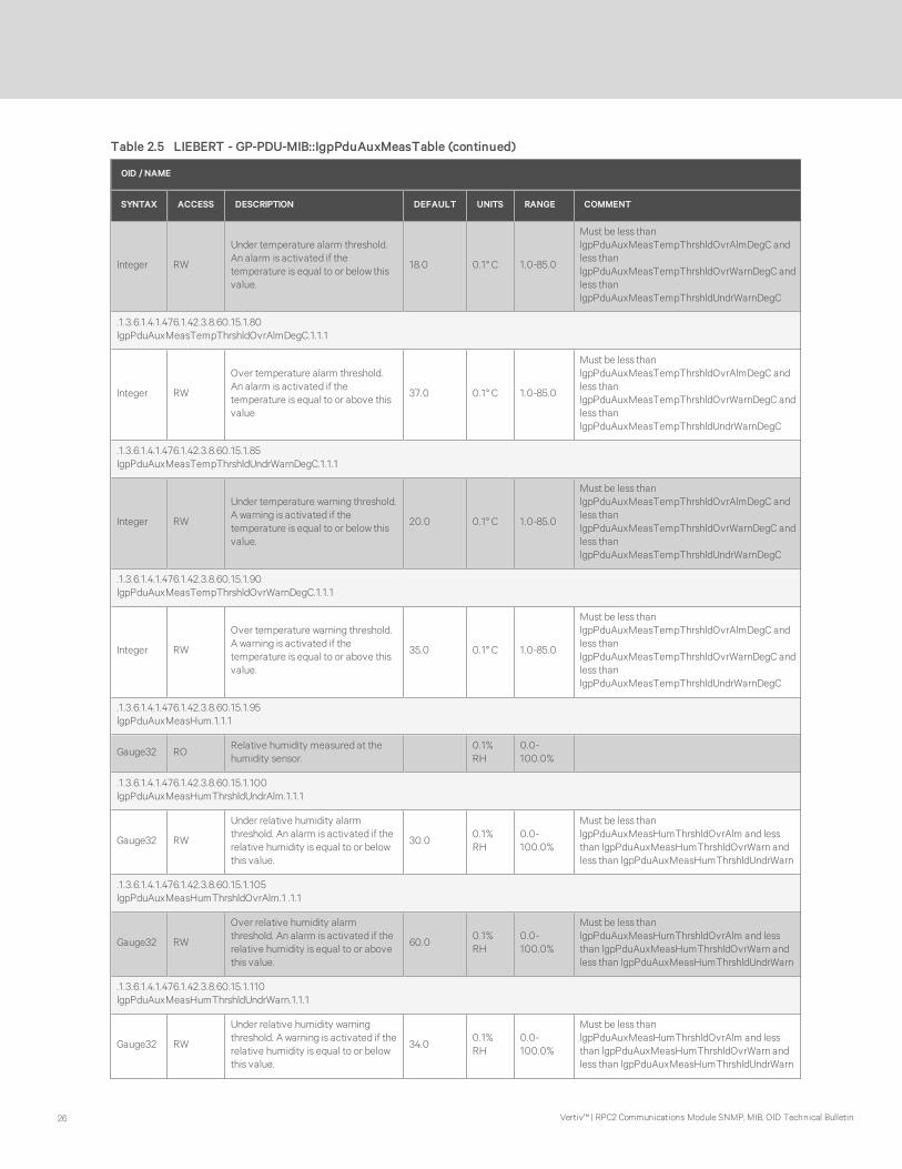
OID / NAME
SYNTAX ACCESS DESCRIPTION DEFAULT UNITS RANGE COMMENT
Integer RW
Under temperature alarm threshold.An alarm is activated if thetemperature is equal to or below thisvalue.
18.0 0.1° C 1.0-85.0
Must be less thanlgpPduAuxMeasTempThrshldOvrAlmDegC andless thanlgpPduAuxMeasTempThrshldOvrWarnDegC andless thanlgpPduAuxMeasTempThrshldUndrWarnDegC
.1.3.6.1.4.1.476.1.42.3.8.60.15.1.80lgpPduAuxMeasTempThrshldOvrAlmDegC.1.1.1
Integer RW
Over temperature alarm threshold.An alarm is activated if thetemperature is equal to or above thisvalue
37.0 0.1° C 1.0-85.0
Must be less thanlgpPduAuxMeasTempThrshldOvrAlmDegC andless thanlgpPduAuxMeasTempThrshldOvrWarnDegC andless thanlgpPduAuxMeasTempThrshldUndrWarnDegC
.1.3.6.1.4.1.476.1.42.3.8.60.15.1.85lgpPduAuxMeasTempThrshldUndrWarnDegC.1.1.1
Integer RW
Under temperature warning threshold.A warning is activated if thetemperature is equal to or below thisvalue.
20.0 0.1° C 1.0-85.0
Must be less thanlgpPduAuxMeasTempThrshldOvrAlmDegC andless thanlgpPduAuxMeasTempThrshldOvrWarnDegC andless thanlgpPduAuxMeasTempThrshldUndrWarnDegC
.1.3.6.1.4.1.476.1.42.3.8.60.15.1.90lgpPduAuxMeasTempThrshldOvrWarnDegC.1.1.1
Integer RW
Over temperature warning threshold.A warning is activated if thetemperature is equal to or above thisvalue.
35.0 0.1° C 1.0-85.0
Must be less thanlgpPduAuxMeasTempThrshldOvrAlmDegC andless thanlgpPduAuxMeasTempThrshldOvrWarnDegC andless thanlgpPduAuxMeasTempThrshldUndrWarnDegC
.1.3.6.1.4.1.476.1.42.3.8.60.15.1.95lgpPduAuxMeasHum.1.1.1
Gauge32 RORelative humidity measured at thehumidity sensor.
0.1%RH
0.0-100.0%
.1.3.6.1.4.1.476.1.42.3.8.60.15.1.100lgpPduAuxMeasHumThrshldUndrAlm.1.1.1
Gauge32 RW
Under relative humidity alarmthreshold. An alarm is activated if therelative humidity is equal to or belowthis value.
30.00.1%RH
0.0-100.0%
Must be less thanlgpPduAuxMeasHumThrshldOvrAlm and lessthan lgpPduAuxMeasHumThrshldOvrWarn andless than lgpPduAuxMeasHumThrshldUndrWarn
.1.3.6.1.4.1.476.1.42.3.8.60.15.1.105lgpPduAuxMeasHumThrshldOvrAlm.1 .1.1
Gauge32 RW
Over relative humidity alarmthreshold. An alarm is activated if therelative humidity is equal to or abovethis value.
60.00.1%RH
0.0-100.0%
Must be less thanlgpPduAuxMeasHumThrshldOvrAlm and lessthan lgpPduAuxMeasHumThrshldOvrWarn andless than lgpPduAuxMeasHumThrshldUndrWarn
.1.3.6.1.4.1.476.1.42.3.8.60.15.1.110lgpPduAuxMeasHumThrshldUndrWarn.1.1.1
Gauge32 RW
Under relative humidity warningthreshold. A warning is activated if therelative humidity is equal to or belowthis value.
34.00.1%RH
0.0-100.0%
Must be less thanlgpPduAuxMeasHumThrshldOvrAlm and lessthan lgpPduAuxMeasHumThrshldOvrWarn andless than lgpPduAuxMeasHumThrshldUndrWarn
Table 2.5 LIEBERT - GP-PDU-MIB::IgpPduAuxMeasTable (continued)
Vertiv™ | RPC2 Communications Module SNMP, MIB, OID Technical Bulletin26

OID / NAME
SYNTAX ACCESS DESCRIPTION DEFAULT UNITS RANGE COMMENT
.1.3.6.1.4.1.476.1.42.3.8.60.15.1.115lgpPduAuxMeasHumThrshldOvrWarn.1.1.1
Gauge32 RW
Over relative humidity warningthreshold. A warning is activated if therelative humidity is equal to or abovethis value.
56.00.1%RH
0.0-100.0%
Must be less thanlgpPduAuxMeasHumThrshldOvrAlm and greaterthan lgpPduAuxMeasHumThrshldUndrWarn andgreater thanlgpPduAuxMeasHumThrshldUndrAlm
.1.3.6.1.4.1.476.1.42.3.8.60.15.1.120lgpPduAuxMeasDrClosureState.2.1.1
Integer RO
Enumerations that describe the stateof the door sensor measurement.
not-specified(0): The door state isunknown.
open(1): The door is in the open state.
closed(2): The door is in the closedstate.
0-2
.1.3.6.1.4.1.476.1.42.3.8.60.15.1.125lgpPduAuxMeasDrClosureConfig.2.1.1
Integer RW
A configuration parameter for thedoor state alarms. This objectprovides the ability to select when adoor closure measurement shouldcause an alarm.
disabled(0):The door state will neverresult in alarm.
alarm-when-open (1): Activate analarm when the door state becomesopen.
0-1
.1.3.6.1.4.1.476.1.42.3.8.60.15.1.130lgpPduAuxMeasCntctClosureState.2.2.1
Integer RO
The state of a contact closure sensormeasurement.
not-specified(0): The contact closurestate is unknown.
open(1): The contact closure is in theopen state.
closed(2): The contact closure is inthe closed state.
not-specified(0)
0-2
.1.3.6.1.4.1.476.1.42.3.8.60.15.1.135lgpPduAuxMeasCntctClosureConfig.2.2.1
Integer RW
Configure contact closure statealarms. This object provides theability to select when a contactclosure measurement should activatean alarm
disabled(0): The contact closurestate will never result in alarm.
alarm-when-open(1): Activate analarm when the contact closure statebecomes open.
disabled(0) 0-2
Table 2.5 LIEBERT - GP-PDU-MIB::IgpPduAuxMeasTable (continued)
2 RPC2 Configuration SNMP OID Tables 27

OID / NAME
SYNTAX ACCESS DESCRIPTION DEFAULT UNITS RANGE COMMENT
alarm-when-closed(2): Activate analarm when the contact closure statebecomes closed.
.1.3.6.1.4.1.476.1.42.3.8.60.15.1.145lgpPduAuxMeasDiffPressure.2.3.1
Integer32 ROPressure difference measured at thedifferential pressure sensor.
pA-125.0 to+125.0
.1.3.6.1.4.1.476.1.42.3.8.60.15.1.150lgpPduAuxMeasDiffPressureThrshldUndrAlm.2.3.1
Integer32 RW
Under differential pressure alarmthreshold. An alarm is activated if thedifferential pressure is equal to orbelow this value.
-100.0 pA-125.0 to+125.0
Must be less thanlgpPduAuxMeasDiffPressureThrshOvrAlm andless thanlgpPduAuxMeasDiffPressureThrshOvrWarn andless thanlgpPduAuxMeasDiffPressureThrshUndrWarn
.1.3.6.1.4.1.476.1.42.3.8.60.15.1.155lgpPduAuxMeasDiffPressureThrshldOvrAlm.2.3.1
Integer32 RW
Over differential pressure alarmthreshold. An alarm is activated if thedifferential pressure is equal to orabove this value.
+100.0 pA-125.0 to+125.0
Must be less thanlgpPduAuxMeasDiffPressureThrshOvrAlm andless thanlgpPduAuxMeasDiffPressureThrshOvrWarn andless thanlgpPduAuxMeasDiffPressureThrshUndrWarn
.1.3.6.1.4.1.476.1.42.3.8.60.15.1.110lgpPduAuxMeasDiffPressureThrshldUndrWarn.2.3.1
Integer32 RW
Under differential pressure warningthreshold. A warning is activated if thedifferential pressure is equal to orbelow this value.
-50.0 pA-125.0 to+125.0
Must be less thanlgpPduAuxMeasDiffPressureThrshOvrAlm andless thanlgpPduAuxMeasDiffPressureThrshOvrWarn andless thanlgpPduAuxMeasDiffPressureThrshUndrWarn
.1.3.6.1.4.1.476.1.42.3.8.60.15.1.115lgpPduAuxMeasDiffPressureThrshldOvrWarn.2.3.1
Integer32 RW
Over differential pressure warningthreshold. A warning is activated if thedifferential pressure is equal to orabove this value.
+50.0 pA-125.0 to+125.0
Must be less thanlgpPduAuxMeasDiffPressureThrshOvrAlm andgreater thanlgpPduAuxMeasDiffPressureThrshUndrWarn andgreater thanlgpPduAuxMeasDiffPressureThrshUndrAlm
Table 2.5 LIEBERT - GP-PDU-MIB::IgpPduAuxMeasTable (continued)
Vertiv™ | RPC2 Communications Module SNMP, MIB, OID Technical Bulletin28
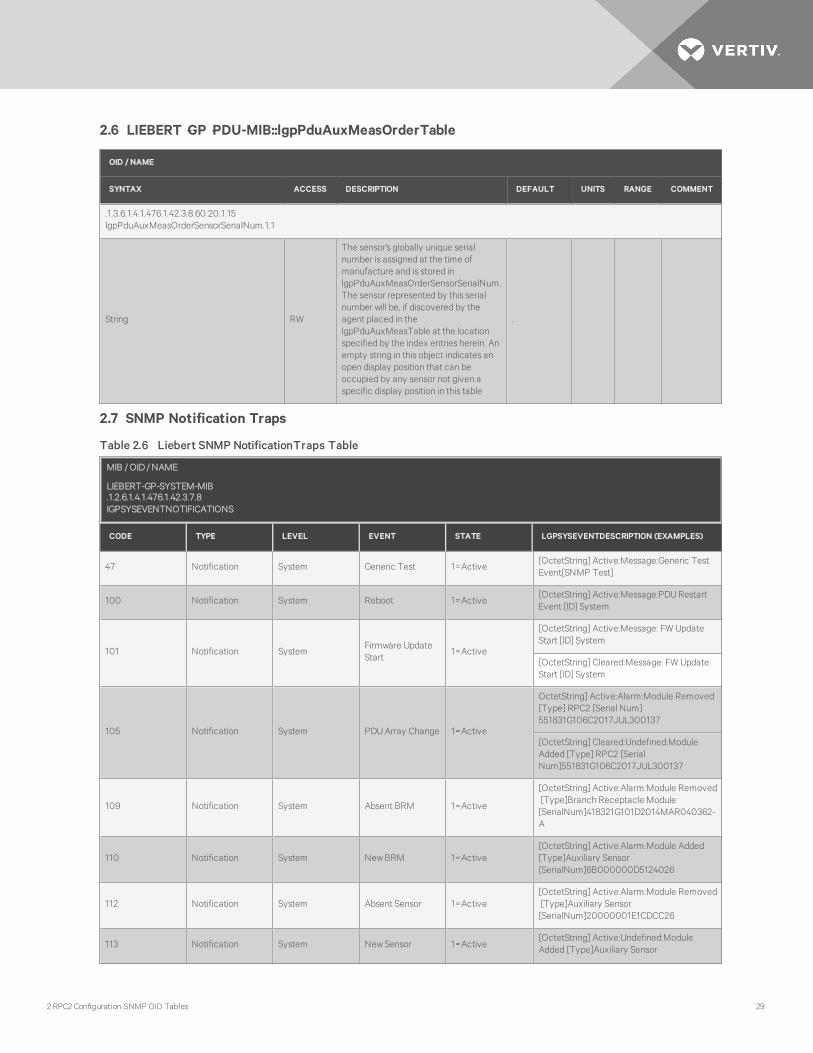
2.6 LIEBERT‐GP‐PDU-MIB::lgpPduAuxMeasOrderTable
OID / NAME
SYNTAX ACCESS DESCRIPTION DEFAULT UNITS RANGE COMMENT
.1.3.6.1.4.1.476.1.42.3.8.60.20.1.15lgpPduAuxMeasOrderSensorSerialNum.1.1
String RW
The sensor's globally unique serialnumber is assigned at the time ofmanufacture and is stored inlgpPduAuxMeasOrderSensorSerialNum.The sensor represented by this serialnumber will be, if discovered by theagent placed in thelgpPduAuxMeasTable at the locationspecified by the index entries herein. Anempty string in this object indicates anopen display position that can beoccupied by any sensor not given aspecific display position in this table
.
2.7 SNMP Notification Traps
MIB / OID / NAME
LIEBERT-GP-SYSTEM-MIB.1.2.6.1.4.1.476.1.42.3.7.8IGPSYSEVENTNOTIFICATIONS
CODE TYPE LEVEL EVENT STATE LGPSYSEVENTDESCRIPTION (EXAMPLES)
47 Notification System Generic Test 1=Active[OctetString] Active:Message:Generic TestEvent[SNMP Test]
100 Notification System Reboot 1=Active[OctetString] Active:Message:PDURestartEvent [ID] System
101 Notification SystemFirmware UpdateStart
1=Active
[OctetString] Active:Message: FW UpdateStart [ID] System
[OctetString] Cleared:Message: FW UpdateStart [ID] System
105 Notification System PDUArray Change 1=Active
OctetString] Active:Alarm:Module Removed[Type] RPC2 [Serial Num]551831G106C2017JUL300137
[OctetString] Cleared:Undefined:ModuleAdded [Type] RPC2 [SerialNum]551831G106C2017JUL300137
109 Notification System Absent BRM 1=Active
[OctetString] Active:Alarm:Module Removed[Type]Branch Receptacle Module[SerialNum]418321G101D2014MAR040362-A
110 Notification System NewBRM 1=Active[OctetString] Active:Alarm:Module Added[Type]Auxiliary Sensor[SerialNum]6B000000D5124026
112 Notification System Absent Sensor 1=Active[OctetString] Active:Alarm:Module Removed[Type]Auxiliary Sensor[SerialNum]20000001E1CDCC26
113 Notification System NewSensor 1=Active[OctetString] Active:Undefined:ModuleAdded [Type]Auxiliary Sensor
Table 2.6 Liebert SNMP NotificationTraps Table
2 RPC2 Configuration SNMP OID Tables 29

MIB / OID / NAME
LIEBERT-GP-SYSTEM-MIB.1.2.6.1.4.1.476.1.42.3.7.8IGPSYSEVENTNOTIFICATIONS
CODE TYPE LEVEL EVENT STATE LGPSYSEVENTDESCRIPTION (EXAMPLES)
[SerialNum]20000001E1CDCC26
114 Alarm System Too Many Sensors
1=Active[OctetString] Active:Alarm:Too ManySensors
2=Cleared[OctetString] Cleared:Alarm:Too ManySensors
201 Alarm PDU Over Current
1=Active
[OctetString] Active:Alarm:PDUOverCurrent L1[Label]MPH2 [V14C2600009][Pole]L1[Value]8.31A[Threshold]2%
2=Cleared[OctetString] Cleared:Alarm:PDUOverCurrent L3[Label]MPH2 [V14C2600009]
202 Warning PDU
Over Current 1=Active
[OctetString] Active:Warning:PDUOverCurrent L1[Label]MPH2 [V14C2600009][Pole]L1[Value]0.40A[Threshold]1%
Clear Over Current 2=Cleared[OctetString] Cleared:Warning:PDUOverCurrent L1[Label]MPH2 [V14C2600009]
203 Alarm PDU LowCurrent
1=Active
[OctetString] Active:Alarm:PDULowCurrentL1[Label]MPH2 [V14C2600009][Pole]L1[Value]0.00A[Threshold]1%
2=Cleared[OctetString]Cleared:Alarm:PDULowCurrentL3[Label]MPH2 [V14C2600009]
204 Alarm PDU Unbalanced Load
1=Active
[OctetString] Active:Alarm:Unbalanced LoadCondition[Label]MPH2 [V14C2600009][Threshold]1%
2=Cleared[OctetString] Cleared:Alarm:UnbalancedLoad Condition[Label]MPH2 [V14C2600009]
205 Alarm PDUOver Current -Neutral
1=Active
[OctetString]Active:Alarm:PDUNeutral OverCurrent[Label]MPH2 [V14C2600009][Value]8.05A[Threshold]2%
2=Cleared[OctetString]Cleared:Alarm:PDUNeutralOver Current[Label]MPH2 [V14C2600009]
206 Warning PDUOver Current -Neutral
1=Active[OctetString]Active:Warning:PDUOverCurrent L1
Table 2.6 Liebert SNMP NotificationTraps Table (continued)
Vertiv™ | RPC2 Communications Module SNMP, MIB, OID Technical Bulletin30

MIB / OID / NAME
LIEBERT-GP-SYSTEM-MIB.1.2.6.1.4.1.476.1.42.3.7.8IGPSYSEVENTNOTIFICATIONS
CODE TYPE LEVEL EVENT STATE LGPSYSEVENTDESCRIPTION (EXAMPLES)
[Label]MPH2 [V14C2600009][Pole]L1[Value]0.40A[Threshold]1%
2=Cleared[OctetString] Cleared:Warning:PDUNeutralOver Current[Label]MPH2 [V14C2600009]
207 Alarm PDU Under Voltage
1=Active
[OctetString] Active:Alarm:PDULowVoltageL3-L1[Label]MPH2 [V14D2600032][Phase]L1N[Value]0.1V
2=Cleared[OctetString] Cleared:Alarm:PDULowVoltage (LN)[Label]MPH2 [V14C2600009]
208 Alarm PDUNeutral VoltageFault
1=Active[OctetString] Active:Alarm:Neutral VoltageFault[Label]MPH2 [V14C2600009]
2=Cleared[OctetString] Cleared:Message:NeutralVoltage Fault[Label]MPH2 [V14C2600009]
300 Alarm Branch
Open CircuitBreaker
1=Active[OctetString] Active:Alarm:Branch BreakerOpen[Label]BR F [V14C2600009]
CB closed 2=Cleared[OctetString] Cleared:Alarm:Branch BreakerOpen[Label]BR F [V14C2600009] ]
302 Alarm Branch Over Current
1=Active
[OctetString] Active:Alarm:Branch OverCurrent[Label]BR A [V14C2600009][Value]0.95A[Threshold]4%
2=Cleared[OctetString] Cleared:Alarm:Branch OverCurrent[Label]BR A [V14C2600009]
303 Warning Branch Over Current
1=Active
[OctetString] Active:Warning:Branch OverCurrent[Label]BR A [V14C2600009][Value]0.39A[Threshold]2%
2=Cleared[OctetString] Cleared:Warning:Branch OverCurrent[Label]BR A [V14C2600009]
304 Alarm Branch LowCurrent
1=Active
[OctetString] Active:Alarm:Branch LowCurrent[Label]BR A [V14C2600009][Value]0.00A[Threshold]20%
2=Cleared[OctetString] Cleared:Alarm:Branch LowCurrent[Label]BR A [V14C2600009
Table 2.6 Liebert SNMP NotificationTraps Table (continued)
2 RPC2 Configuration SNMP OID Tables 31

MIB / OID / NAME
LIEBERT-GP-SYSTEM-MIB.1.2.6.1.4.1.476.1.42.3.7.8IGPSYSEVENTNOTIFICATIONS
CODE TYPE LEVEL EVENT STATE LGPSYSEVENTDESCRIPTION (EXAMPLES)
305 Alarm Branch Under Voltage
1=Active
[OctetString] Active:Alarm:Branch LowVoltage (LN)[Label]Branch A[Value]0.9V
2=Cleared[OctetString] Cleared:Alarm:Branch LowVoltage (LN)[Label]Branch A
306 Alarm Branch Loss of Load
1=Active[OctetString]Active:Alarm:Branch Load Loss[Label]BR A [V15K2600562]
2=Cleared[OctetString]Cleared:Alarm:Branch LoadLoss[Label]BR A [V15K2600562]
400 Notification Receptacle Absent Load 1=Active[OctetString]Active:Message:ReceptacleLoad Removed[Label]RCP A-1[V16L2600645]
401 Notification Receptacle NewLoad 1=Active[OctetString]Active:Message:ReceptacleLoad Added[Label]RCP A-1 [V16L2600645]
403 Alarm Receptacle Over Current
1=Active
[OctetString]Active:Alarm:Receptacle OverCurrent[Label]RCP A-1 [V16L2600645][Value]0.41A[Threshold]2%
2=Cleared[OctetString]Cleared:Alarm:Receptacle OverCurrent[Label]RCP A-1 [V16L2600645]
404 Warning Receptacle Over Current
1=Active
[OctetString]Active:Warning:ReceptacleOver Current[Label]RCP A-1 [V16L2600645][Value]0.40A[Threshold]2%
2=Cleared[OctetString]Cleared:Warning:ReceptacleOver Current[Label]RCP A-1 [V16L2600645]
405 Alarm Receptacle LowCurrent
1=Active
[OctetString] Active:Alarm:Receptacle LowCurrent[Label]RCP A-1 [V16L2600645][Value]0.00A[Threshold]20%
2=Cleared[OctetString] Cleared:Alarm:Receptacle LowCurrent[Label]RCP A-1 [V16L2600645]
406 Notification Receptacle Power ON 1=Active[OctetString] Active:Message:ReceptaclePower State - On[Label]RCP E-1[V14C2600009]
407 Notification Receptacle Power OFF 1=Active[OctetString] Active:Message:ReceptaclePower State - Off[Label]RCP E-1 [V14C2600009]
500 Alarm Sensor High Humidity 1=Active[OctetString] Active:Alarm:Over RelativeHumidity[Label]20000001E1CDCC26
Table 2.6 Liebert SNMP NotificationTraps Table (continued)
Vertiv™ | RPC2 Communications Module SNMP, MIB, OID Technical Bulletin32

MIB / OID / NAME
LIEBERT-GP-SYSTEM-MIB.1.2.6.1.4.1.476.1.42.3.7.8IGPSYSEVENTNOTIFICATIONS
CODE TYPE LEVEL EVENT STATE LGPSYSEVENTDESCRIPTION (EXAMPLES)
[Value]26.5%RH[Threshold]26.0%RH
2=Cleared[OctetString] Cleared:Alarm:Over RelativeHumidity[Label]20000001E1CDCC26
501 Warning Sensor High Humidity
1=Active
[OctetString] Active:Warning:Over RelativeHumidity[Label]20000001E1CDCC26[Value]26.5%RH[Threshold]26.0%RH
2=Cleared[OctetString] Cleared:Warning:Over RelativeHumidity[Label]20000001E1CDCC26
502 Alarm Sensor LowHumidity
1=Active
[OctetString] Active:Alarm:Under RelativeHumidity[Label]20000001E1CDCC26[Value]27.1%RH[Threshold]28.0%RH
2=Cleared[OctetString] Cleared:Alarm:Under RelativeHumidity[Label]20000001E1CDCC26
503 Warning Sensor
LowHumidity 1=Active
[OctetString] Active:Warning:Under RelativeHumidity[Label]20000001E1CDCC26[Value]33.8%RH[Threshold]34.0%RH
2=Cleared[OctetString] Cleared:Warning:UnderRelative Humidity[Label]20000001E1CDCC26
504 Alarm Sensor Over Temperature
1=Active
[OctetString] Active:Alarm:OverTemperature[Label]A80000005803C042[Value]24.0 C[Threshold]23.0 C
2=Cleared[OctetString] Cleared:Alarm:OverTemperature[Label]A80000005803C042
505 Warning Sensor Over Temperature
1=Active
[OctetString] Active:Warning:OverTemperature[Label]A80000005803C042[Value]24.0 C[Threshold]22.0 C
2=Cleared
[OctetString] Active:Warning:OverTemperature[Label]A80000005803C042[Value]24.0 C[Threshold]22.0 C
506 Alarm SensorUnderTemperature
1=Active
[OctetString] Active:Alarm:UnderTemperature[Label]A80000005803C042[Value]24.1 C[Threshold]25.0 C
2=Cleared[OctetString] Cleared:Alarm:UnderTemperature[Label]A80000005803C042
Table 2.6 Liebert SNMP NotificationTraps Table (continued)
2 RPC2 Configuration SNMP OID Tables 33

MIB / OID / NAME
LIEBERT-GP-SYSTEM-MIB.1.2.6.1.4.1.476.1.42.3.7.8IGPSYSEVENTNOTIFICATIONS
CODE TYPE LEVEL EVENT STATE LGPSYSEVENTDESCRIPTION (EXAMPLES)
507 Warning SensorUnderTemperature
1=Active
[OctetString] Active:Warning:UnderTemperature[Label]A80000005803C042[Value]24.1 C[Threshold]26.0 C
2=Cleared[OctetString] Cleared:Warning:UnderTemperature[Label]A80000005803C042
508 Alarm Sensor Open Door
1=Active[OctetString] Active:Alarm:Door Open[Label]410000000C3F7A20-1
2=Cleared[OctetString] Cleared:Alarm:Door Open[Label]410000000C3F7A20-1
509 Alarm Sensor Open Contract 1=Active
[OctetString] Active:Alarm:Contact ClosureOpen[Label]2800000013F0EB20-1
[OctetString] Cleared:Alarm:Contact ClosureOpen[Label]2800000013F0EB20-1
510 Alarm Sensor Close Contract
1=Active[OctetString] Active:Alarm:Contact ClosureClosed[Label]2800000013F0EB20-2
2=Cleared[OctetString] Cleared:Alarm:Contact ClosureClosed[Label]2800000013F0EB20-2
513 Alarm SensorOver DifferentialPressure
1=Active
OctetString] Active:Alarm: Over DifferentialPressure[Label]650050000004087E[Value]9.0Pa[Threshold]5.0Pa
2=Cleared[OctetString] Cleared:Alarm:Over DifferentialPressure[Label] 650050000004087E
514 Warning SensorOver DifferentialPressure
1=Active
OctetString] Active:Alarm: Over DifferentialPressure[Label]650050000004087E[Value]7.0Pa[Threshold]5.0Pa
2=Cleared[OctetString] Cleared:Alarm:Over DifferentialPressure[Label] 650050000004087E
515 Alarm SensorUnder DifferentialPressure
1=Active
[OctetString] Active:Alarm:Under DifferentialPressure[Label]650050000004087E[Value]3.0Pa[Threshold]5.0Pa
Table 2.6 Liebert SNMP NotificationTraps Table (continued)
Vertiv™ | RPC2 Communications Module SNMP, MIB, OID Technical Bulletin34

MIB / OID / NAME
LIEBERT-GP-SYSTEM-MIB.1.2.6.1.4.1.476.1.42.3.7.8IGPSYSEVENTNOTIFICATIONS
CODE TYPE LEVEL EVENT STATE LGPSYSEVENTDESCRIPTION (EXAMPLES)
2=Cleared[OctetString] Cleared:Alarm:UnderDifferential Pressure[Label] 650050000004087E
516 Warning SensorUnder DifferentialPressure
1=Active
[OctetString] Active:Alarm:Under DifferentialPressure[Label]650050000004087E[Value]0.0Pa[Threshold]5.0Pa
2=Cleared[OctetString] Cleared:Warning:UnderDifferential Pressure[Label] 650050000004087E
Table 2.6 Liebert SNMP NotificationTraps Table (continued)
2 RPC2 Configuration SNMP OID Tables 35

2.8 SNMP Alarm Traps
NOTE: For V1, the information in the State column is specific to the trap. For V2, the information in the State column isthe suffix of lgpnotifications OID, e.g. .0.1 means Active.
MIB / OID / NAME
LIEBERT-GP-REGISTRATION-MIB.1.2.6.1.4.1.476.1.42.3.3LGPNOTIFICATIONS
CODE TYPE LEVEL EVENT STATE LGPCONDITIONID/LGPCONDITIONDESCRIPTION
Notification SystemFirmware UpdateRequired
1=Active.1.3.6.1.4.1.476.1.42.3.2.7.1.4550lgpCondId4550FirmwareUpdateRequired
Notification SystemV2 Event ConditionAdded
1=Active.1.3.6.1.4.1.476.1.42.3.3.0.1lgpEventConditionEntryAdded
Notification SystemV2 Event ConditionRemoved
1=Active.1.3.6.1.4.1.476.1.42.3.3.0.2lgpEventConditionEntryRemoved
47 Notification System Generic Test 1=Active.1.3.6.1.4.1.476.1.42.3.2.1.4551lgpCondId4551GenericTestEvent
100 Notification System Reboot 1=Active.1.3.6.1.4.1.476.1.42.3.2.7.1.6194lgpCondId6194SystemRebootCommandIssued
101 Notification System Firmware Update Start 1=Active.1.3.6.1.4.1.476.1.42.3.2.7.1.6210lgpCondId6210FirmwareUpdateInProgress
106 Notification System PDUPower on Reset 1=Active.1.3.6.1.4.1.476.1.42.3.2.1.6450lgpCondId6450PDUPoweredOn
109 Notification System Absent BRM 1=Active.1.3.6.1.4.1.476.1.42.3.2.7.1.4523lgpCondId4523ModuleRemoved
110 Notification System NewBRM 1=Active.1.3.6.1.4.1.476.1.42.3.2.7.1.4524lgpCondId4524ModuleAdded
111 Alarm SystemDevice ChangeAcknowledge Pending
1=Active.1.3.6.1.4.1.476.1.42.3.2.1.4495lgpCondId4495DeviceConfigurationChange
112 Notification System Absent Sensor 1=Active.1.3.6.1.4.1.476.1.42.3.2.7.1.6204lgpCondId6204SensorRemoved
113 Notification System NewSensor 1=Active.1.3.6.1.4.1.476.1.42.3.2.7.1.6203lgpCondId6203SensorAdded
114 Alarm System Too Many Sensors1=Active
2=Cleared
.1.3.6.1.4.1.476.1.42.3.2.1.5423lgpCondId5423TooManySensors
200 Alarm PDU Hardware Fault1=Active
2=Cleared
.1.3.6.1.4.1.476.1.42.3.2.1.4502lgpCondId4502PDUFailure
201 Alarm PDU Over Current1=Active
2=Cleared
.1.3.6.1.4.1.476.1.42.3.2.7.1.4470lgpCondId4470PDUOverCurrentL3
201 Alarm PDU Over Current1=Active
2=Cleared
.1.3.6.1.4.1.476.1.42.3.2.1.4448lgpCondId4448PDUOverCurrent
201 Alarm PDU Over Current1=Active
2=Cleared
.1.3.6.1.4.1.476.1.42.3.2.1.4468lgpCondId4468PDUOverCurrentL1
201 Alarm PDU Over Current1=Active
2=Cleared
.1.3.6.1.4.1.476.1.42.3.2.1.4469lgpCondId4469PDUOverCurrentL2
Table 2.7 SNMP Alarm Traps
Vertiv™ | RPC2 Communications Module SNMP, MIB, OID Technical Bulletin36

MIB / OID / NAME
LIEBERT-GP-REGISTRATION-MIB.1.2.6.1.4.1.476.1.42.3.3LGPNOTIFICATIONS
CODE TYPE LEVEL EVENT STATE LGPCONDITIONID/LGPCONDITIONDESCRIPTION
202 Warning PDU Over Current1=Active
2=Cleared
.1.3.6.1.4.1.476.1.42.3.2.1.4470lgpCondId4470PDUOverCurrentL3
203 Alarm PDU LowCurrent1=Active
2=Cleared
.1.3.6.1.4.1.476.1.42.3.2.7.1.4473lgpCondId4473PDUUnderCurrentL3
203 Alarm PDU LowCurrent1=Active
2=Cleared
.1.3.6.1.4.1.476.1.42.3.2.1.4449lgpCondId4449PDUUnderCurrent
203 Alarm PDU LowCurrent1=Active
2=Cleared
.1.3.6.1.4.1.476.1.42.3.2.1.4471lgpCondId4471PDUUnderCurrentL1
203 Alarm PDU LowCurrent1=Active
2=Cleared
.1.3.6.1.4.1.476.1.42.3.2.1.4472lgpCondId4472PDUUnderCurrentL2
204 Alarm PDU Unbalanced Load1=Active
2=Cleared
.1.3.6.1.4.1.476.1.42.3.2.7.1.5928lgpCondId5928UnbalancedLoadCondition
205 Alarm PDU Over Current - Neutral1=Active
2=Cleared
.1.3.6.1.4.1.476.1.42.3.2.7.1.5524lgpCondId5524PDUNeutralOverCurrent
206 Warning PDU Over Current - Neutral1=Active
2=Cleared
.1.3.6.1.4.1.476.1.42.3.2.7.1.5524lgpCondId5524PDUNeutralOverCurrent
207 Alarm PDU Under Voltage1=Active
2=Cleared
.1.3.6.1.4.1.476.1.42.3.2.7.1.5780lgpCondId5780PDULowVoltageL3L1
207 Alarm PDU Under Voltage1=Active
2=Cleared
.1.3.6.1.4.1.476.1.42.3.2.1.5776lgpCondId5776PDULowVoltageLN
207 Alarm PDU Under Voltage1=Active
2=Cleared
.1.3.6.1.4.1.476.1.42.3.2.1.5777lgpCondId5777PDULowVoltageLL
207 Alarm PDU Under Voltage1=Active
2=Cleared
.1.3.6.1.4.1.476.1.42.3.2.1.5778lgpCondId5778PDULowVoltageL1L2
207 Alarm PDU Under Voltage1=Active
2=Cleared
.1.3.6.1.4.1.476.1.42.3.2.1.5779lgpCondId5779PDULowVoltageL2L3
207 Alarm PDU Under Voltage1=Active
2=Cleared
.1.3.6.1.4.1.476.1.42.3.2.1.5781lgpCondId5781PDULowVoltageL1N
207 Alarm PDU Under Voltage1=Active
2=Cleared
.1.3.6.1.4.1.476.1.42.3.2.1.5782lgpCondId5782PDULowVoltageL2N
207 Alarm PDU Under Voltage1=Active
2=Cleared
.1.3.6.1.4.1.476.1.42.3.2.1.5783lgpCondId5783PDULowVoltageL3N
208 Alarm PDU Neutral Voltage Fault1=Active
2=Cleared
.1.3.6.1.4.1.476.1.42.3.2.7.1.6221lgpCondId6221NeutralVoltageFault
209 Alarm Branch Over Current - Residual1=Active
2=Cleared
.1.3.6.1.4.1.476.1.42.3.2.1.6693lgpCondId6693BranchResidualOverCurrent
Table 2.7 SNMP Alarm Traps (continued)
2 RPC2 Configuration SNMP OID Tables 37

MIB / OID / NAME
LIEBERT-GP-REGISTRATION-MIB.1.2.6.1.4.1.476.1.42.3.3LGPNOTIFICATIONS
CODE TYPE LEVEL EVENT STATE LGPCONDITIONID/LGPCONDITIONDESCRIPTION
209 Alarm Receptacle Over Current - Residual1=Active
2=Cleared
.1.3.6.1.4.1.476.1.42.3.2.1.6694lgpCondId6694ReceptacleResidualOverCurrent
211 Alarm PDU Over Current Protection1=Active
2=Cleared
.1.3.6.1.4.1.476.1.42.3.2.7.1.6527lgpCondId6527PDUOverCurrentProtection
211 Alarm Branch Over Current Protection1=Active
2=Cleared
.1.3.6.1.4.1.476.1.42.3.2.1.5939lgpCondId5939BranchOverCurrentProtection
300 Alarm BranchOpen Circuit Breaker
CB Closed
1=Active
2=Cleared
.1.3.6.1.4.1.476.1.42.3.2.7.1.4494lgpCondId4494BranchBreakerOpen
302 Alarm Branch Over Current1=Active
2=Cleared
.1.3.6.1.4.1.476.1.42.3.2.7.1.4406lgpCondId4406BranchOverCurrent
302 Alarm Branch Over Current1=Active
2=Cleared
.1.3.6.1.4.1.476.1.42.3.2.1.4416lgpCondId4416BranchOverCurrent
302 Warning Branch Over Current1=Active
2=Cleared
.1.3.6.1.4.1.476.1.42.3.2.1.4416lgpCondId4416BranchOverCurrent
303 Warning Branch Over Current1=Active
2=Cleared
.1.3.6.1.4.1.476.1.42.3.2.7.1.4406lgpCondId4406BranchOverCurrent
304 Alarm Branch LowCurrent1=Active
2=Cleared
.1.3.6.1.4.1.476.1.42.3.2.7.1.4407 2=ClearedlgpCondId4407BranchUnderCurrent
304 Alarm Branch LowCurrent1=Active
2=Cleared
.1.3.6.1.4.1.476.1.42.3.2.1.4417lgpCondId4417BranchUnderCurrent
305 Alarm Branch Under Voltage1=Active
2=Cleared
.1.3.6.1.4.1.476.1.42.3.2.7.1.5784lgpCondId5784BranchLowVoltageLN
305 Alarm Branch Under Voltage1=Active
2=Cleared
.1.3.6.1.4.1.476.1.42.3.2.1.5785lgpCondId5785BranchLowVoltageLL
305 Alarm Branch Under Voltage1=Active
2=Cleared
.1.3.6.1.4.1.476.1.42.3.2.1.5948lgpCondId5948BranchLowVoltageLL
305 Alarm Branch Under Voltage1=Active
2=Cleared
.1.3.6.1.4.1.476.1.42.3.2.1.5786lgpCondId5786BranchLowVoltage
306 Alarm Branch Loss of Load1=Active
2=Cleared
.1.3.6.1.4.1.476.1.42.3.2.1.6222lgpCondId6222BranchLoadLoss
307 Alarm Branch Hardware Fault1=Active
2=Cleared
.1.3.6.1.4.1.476.1.42.3.2.1.4421lgpCondId4421BranchFailure
400 Notification Receptacle Absent Load 1=Active.1.3.6.1.4.1.476.1.42.3.2.7.1.4508lgpCondId4508ReceptacleLoadRemoved
401 Notification Receptacle NewLoad 1=Active.1.3.6.1.4.1.476.1.42.3.2.7.1.4509lgpCondId4509ReceptacleLoadAdded
403 Alarm Receptacle Over Current 1=Active .1.3.6.1.4.1.476.1.42.3.2.7.1.4360
Table 2.7 SNMP Alarm Traps (continued)
Vertiv™ | RPC2 Communications Module SNMP, MIB, OID Technical Bulletin38

MIB / OID / NAME
LIEBERT-GP-REGISTRATION-MIB.1.2.6.1.4.1.476.1.42.3.3LGPNOTIFICATIONS
CODE TYPE LEVEL EVENT STATE LGPCONDITIONID/LGPCONDITIONDESCRIPTION
2=Cleared lgpCondId4360ReceptacleOverCurrent
404 Warning Receptacle Over Current1=Active
2=Cleared
.1.3.6.1.4.1.476.1.42.3.2.7.1.4360lgpCondId4360ReceptacleOverCurrent
405 Alarm Receptacle LowCurrent1=Active
2=Cleared
.1.3.6.1.4.1.476.1.42.3.2.7.1.4361lgpCondId4361ReceptacleUnderCurrent
406 Notification Receptacle Power ON 1=Active.1.3.6.1.4.1.476.1.42.3.2.7.1.4492lgpCondId4492ReceptaclePowerStateOn
407 Notification Receptacle Power OFF 1=Active.1.3.6.1.4.1.476.1.42.3.2.7.1.4493lgpCondId4493ReceptaclePowerStateOff
500 Alarm Sensor High Humidity1=Active
2=Cleared
.1.3.6.1.4.1.476.1.42.3.2.7.1.4588lgpCondId4588OverRelativeHumidity
501 Warning Sensor High Humidity1=Active
2=Cleared
.1.3.6.1.4.1.476.1.42.3.2.7.1.4588lgpCondId4588OverRelativeHumidity
502 Alarm Sensor LowHumidity1=Active
2=Cleared
.1.3.6.1.4.1.476.1.42.3.2.7.1.4589[OID] lgpCondId4589UnderRelativeHumidity
503 Warning Sensor LowHumidity1=Active
2=Cleared
.1.3.6.1.4.1.476.1.42.3.2.7.1.4589[OID] lgpCondId4589UnderRelativeHumidity
504 Alarm Sensor Over Temperature1=Active
2=Cleared
.1.3.6.1.4.1.476.1.42.3.2.7.1.4580[OID] lgpCondId4580OverTemperature
505 Warning Sensor Over Temperature1=Active
2=Cleared
.1.3.6.1.4.1.476.1.42.3.2.7.1.4580[OID] lgpCondId4580OverTemperature
506 Alarm Sensor Under Temperature1=Active
2=Cleared
.1.3.6.1.4.1.476.1.42.3.2.7.1.4581[OID] lgpCondId4581UnderTemperature
507 Warning Sensor Under Temperature1=Active
2=Cleared
.1.3.6.1.4.1.476.1.42.3.2.7.1.4581[OID] lgpCondId4581UnderTemperature
508 Alarm Sensor Open Door1=Active
2=Cleared
.1.3.6.1.4.1.476.1.42.3.2.1.5471[OID] lgpCondId5471DoorOpen
509 Alarm Sensor Open Contract1=Active
2=Cleared
.1.3.6.1.4.1.476.1.42.3.2.1.5479[OID] lgpCondId5479ContactClosureOpen
510 Alarm Sensor Close Contract1=Active
2=Cleared
.1.3.6.1.4.1.476.1.42.3.2.1.5480[OID] lgpCondId5480ContactClosureClosed
511 Alarm Sensor Leak Detected1=Active
2=Cleared
.1.3.6.1.4.1.476.1.42.3.2.7.1.6205[OID] lgpCondId6205WaterLeakDetected
Table 2.7 SNMP Alarm Traps (continued)
2 RPC2 Configuration SNMP OID Tables 39

Vertiv™ | RPC2 Communications Module SNMP, MIB, OID Technical Bulletin40

Vertiv™ | RPC2 Communications Module SNMP, MIB, OID Technical Bulletin

VertivCo.com | Vertiv Headquarters, 1050 Dearborn Drive, Columbus, OH, 43085, USA
© 2018 Vertiv Co. All rights reserved. Vertiv and the Vertiv logo are trademarks or registered trademarks of Vertiv Co. All other names and logos referred to are trade names,trademarks or registered trademarks of their respective owners. While every precaution has been taken to ensure accuracy and completeness herein, Vertiv Co. assumes noresponsibility, and disclaims all liability, for damages resulting from use of this information or for any errors or omissions. Specifications are subject to change without notice.
590-1768-501A