
RPC 30/40, 30/50 - Brooks Construction · The RPC 30/40 30/50 gearbox contains two shafts gears and...
69
RPC 30/40, 30/50
Transcript of RPC 30/40, 30/50 - Brooks Construction · The RPC 30/40 30/50 gearbox contains two shafts gears and...

RPC 30/40, 30/50

The RPC 30/40 30/50 is the smallest of the range of
reversible plate compactors. 140 – 200kg class plate.
Two sizes of base plates, 30/40, 400mm width.
30/50, 500mm width.
Petrol Honda or Diesel options, Hatz
Centrifugal force 30 kn.

Controls (Basic)
choke
Throttle
Controls and basic maintenance is covered in the
operators manual.

Drive is through a centrifugal clutch via a
drive belt.
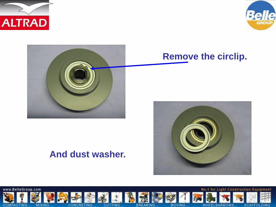
Remove the circlip.
And dust washer.

Centre can now be
tapped out.
Shoes and springs can be
replaced.

A good guide to tension is
to be able to turn belt
through 90 degrees.
The hydraulic handle head assembly is
a simple rack and pinion type pump,
with one main seal and O rings,

Hydraulic Head internal parts

Hydraulic external parts
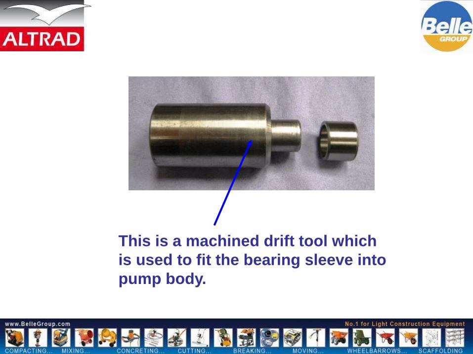
This is a machined drift tool which
is used to fit the bearing sleeve into
pump body.

Fit the bearing into the
head body as shown,

Fit seal to piston
rack shaft

This simple gauge is used to determine position
of piston rack pin on assembly
49mm

Place head body on to
the gauge.

Fit the two O rings to the pinion shaft.

Insert into the
body

Place the shaft in the
body and mesh with
pinion shaft.

The gauge will then allow
the correct positioning of
the two shafts.
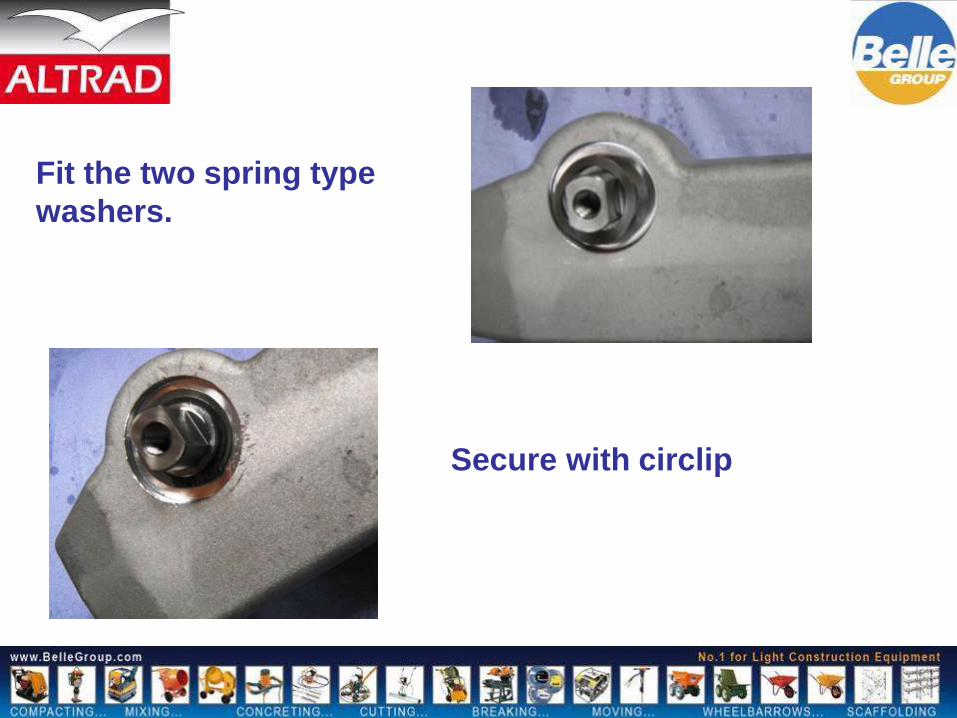
Fit the two spring type
washers.
Secure with circlip

Fit O ring to guide.
Now fit guide into head.

Fit the bracket, and the four
bolts and secure.

Fit the adaptor
and seal.

Head is now complete
and ready to be fitted
to machine.
Note the position of
the flats on the shaft.
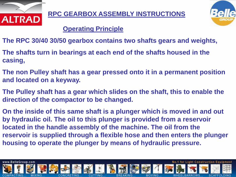
Operating Principle
The RPC 30/40 30/50 gearbox contains two shafts gears and weights,
The shafts turn in bearings at each end of the shafts housed in the
casing,
The non Pulley shaft has a gear pressed onto it in a permanent position
and located on a keyway.
The Pulley shaft has a gear which slides on the shaft, this to enable the
direction of the compactor to be changed.
On the inside of this same shaft is a plunger which is moved in and out
by hydraulic oil. The oil to this plunger is provided from a reservoir
located in the handle assembly of the machine. The oil from the
reservoir is supplied through a flexible hose and then enters the plunger
housing to operate the plunger by means of hydraulic pressure.
RPC GEARBOX ASSEMBLY INSTRUCTIONS

Before assembly all items need to be clean
In normal assembly all items are cleaned by a
hot wash

Fitting of gear to non pulley shaft.
The gear is pressed onto the shaft and located
by the keyway,
Note position of
white
timing dot on gear
This must be at
right
hand side with
keyway
At front.

Note position of oil
plug.
This is used as a
reference point.
Press first bearing into casing as
shown.
Fitted and secured to 35nm

When pressing the bearing in to the gearbox casing,
the end cap is used to determine the correct distance.
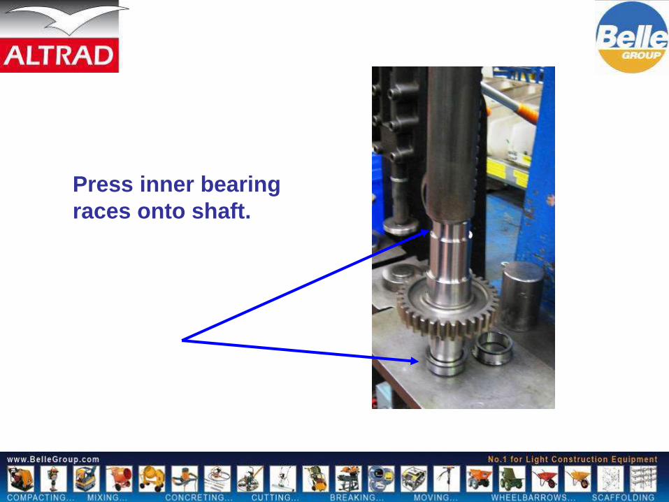
Press inner bearing
races onto shaft.

Fit the shaft to the
casing as shown, note
position of gear.
Fit remaining bearing
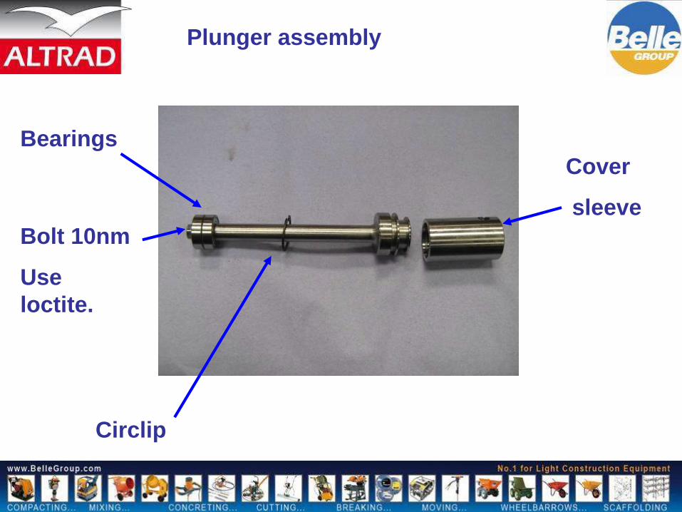
Cover
sleeve
Circlip
Plunger assembly
Bearings
Bolt 10nm
Use
loctite.

Plunger assembly
Place circlip over
assy
Press bearings and cover sleeve on.

Fit circlip into
bearing cap

Fit bearing to piston
shaft.
Take note of position
keyway facing, at the
top of the shaft,
And slot at bottom of
shaft,

Slide circlip up
to bearing.
But not fitted
into groove at
this stage.
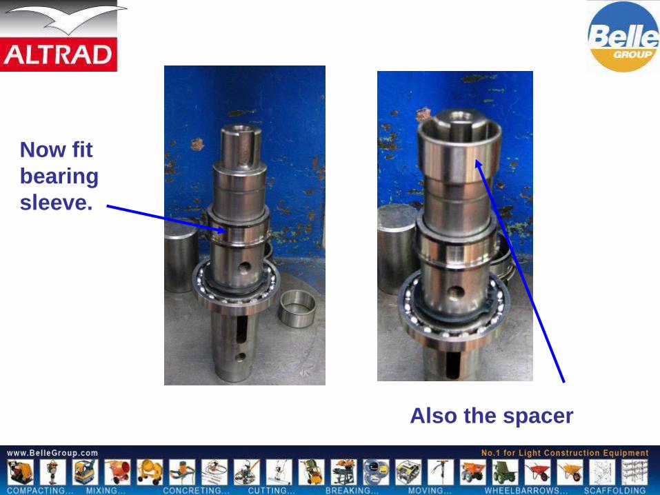
Now fit
bearing
sleeve.
Also the spacer

Insert plunger
assembly into
piston shaft
The dowel pin now is fitted through the slot in the
shaft and locates into the hole in the plunger cap.

Location
hole

This shows correct
position of dowel pin
when fitted to shaft
through plunger
assembly.
Dowel pin should
protrude equal length
either side of shaft.
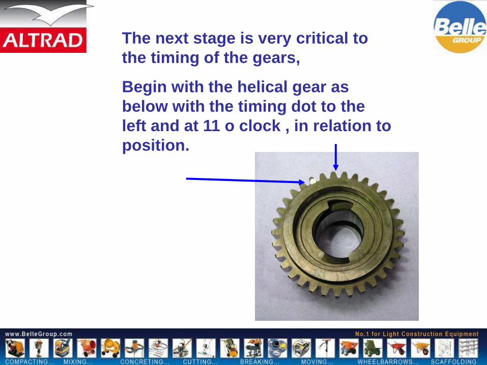
The next stage is very critical to
the timing of the gears,
Begin with the helical gear as
below with the timing dot to the
left and at 11 o clock , in relation to
position.

Place the piston
shaft in the gear,
Note that the Keyway
and bolt holes face
towards you.
Keyway
Weight bolt holes

With the dowel pin on
the bottom of the slot,
and holding the shaft,
carefully lift the helical
gear up the shaft,
turning the gear at the
same time.

The helical gear should
be lifted up sharply so
as to locate on the
bearing,
Once this is done, note
position of the timing
mark.
Gear held by bearing

Now very carefully turn the
whole shaft through 180
degrees,
Still holding the shaft
continue to turn the
helical gear until the
plunger drops, you will
note this will happen
quite suddenly.

The remaining inner
bearing race now
needs to be fitted,
Great care must be
taken not to disturb
the gear on the
shaft during fitting.

Insert complete shaft into casing as
shown, first from left to right.
Then pass
through carefully
to left hand side
of casing.

Note, now the position of the gear
(flush against the casing)
Now from the opposite end of the gear
shaft , gently tap the shaft with soft
type hammer until the
bearing is almost flush with the
helical gear.

Now fit circlip, (already on shaft) to groove as shown,
When bearing has located into helical gear to allow this.
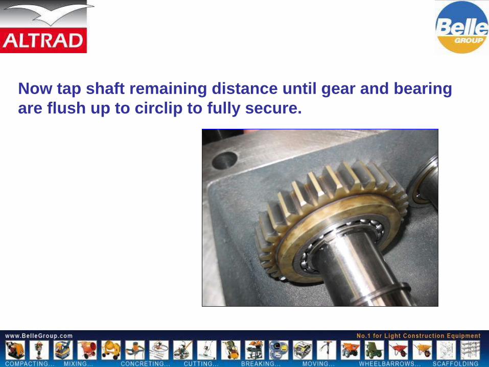
Now tap shaft remaining distance until gear and bearing
are flush up to circlip to fully secure.

Fit bearing to casing at
end of shaft where
plunger locates.
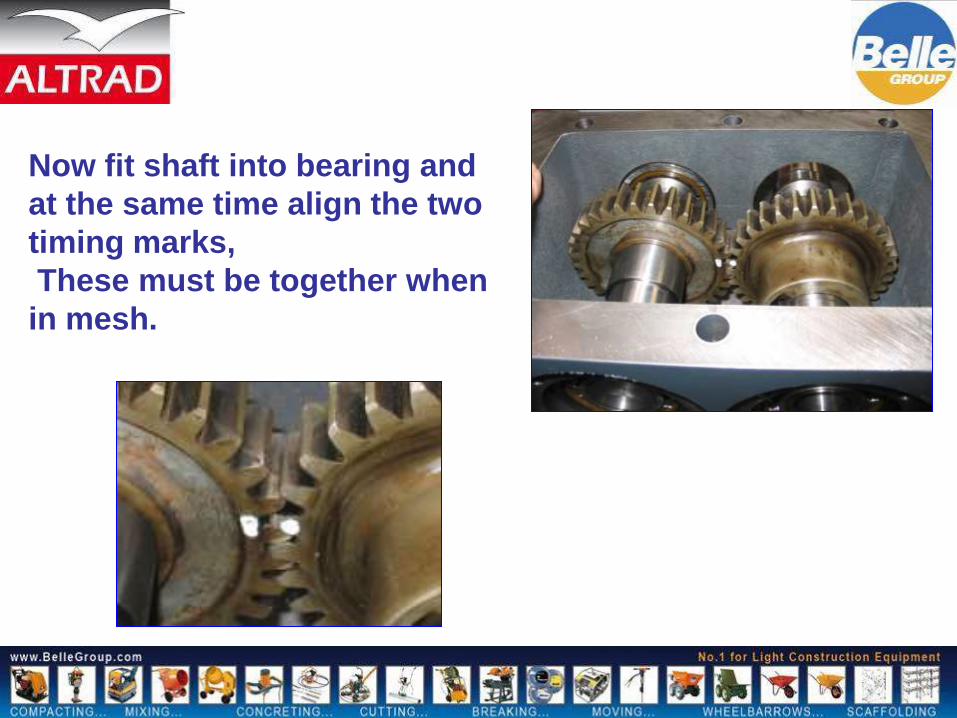
Now fit shaft into bearing and
at the same time align the two
timing marks,
These must be together when
in mesh.
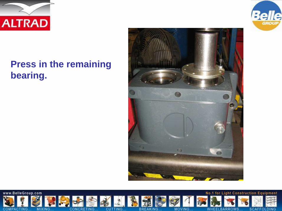
Press in the remaining
bearing.

Timing check
Keyway
pointing
down.
Bolt holes for
weights in
this position.

Hold this gear
Move this gear in
direction of arrow.
As you move the gear
the weight holes should
always go under and not
appear on the top face, if
they do appear on the
top then the helical gear
is 180 degrees out, and
will need correcting.

The next stage is to fit the
weights these are secured by
two different lengths of bolt
so it is important that the
short bolts are used only on
the shaft which houses the
piston.
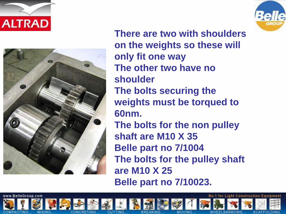
There are two with shoulders
on the weights so these will
only fit one way
The other two have no
shoulder
The bolts securing the
weights must be torqued to
60nm.
The bolts for the non pulley
shaft are M10 X 35
Belle part no 7/1004
The bolts for the pulley shaft
are M10 X 25
Belle part no 7/10023.
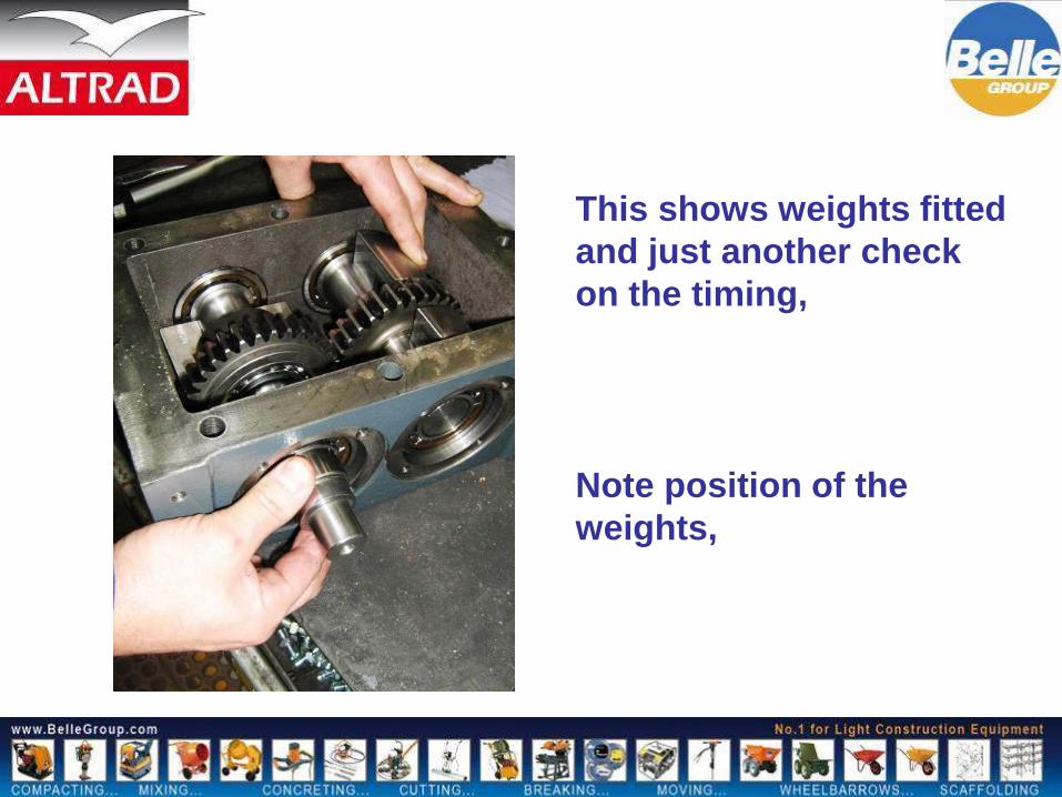
This shows weights fitted
and just another check
on the timing,
Note position of the
weights,

Fit oil seal to end cap
Silicone is used to
seal the caps.

Cap bolts are tensioned to 10nm

Fit the back plate

Fit pulley with key
Bolt that secures pulley is
hollow up the centre and has a
hole in one of the flats.
This is the gearbox breather,
Do not over tighten the bolt.

Smear a film of oil in
the plunger cap
housing.
Fit the seal carefully to the
plunger.
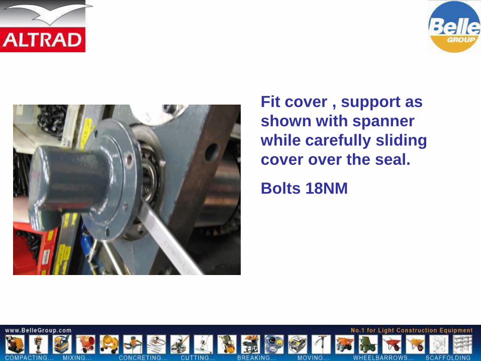
Fit cover , support as
shown with spanner
while carefully sliding
cover over the seal.
Bolts 18NM

Fit the adaptor to the cover
for the hydraulic hose
Tighten to 35nm.

This now completes the build of the gearbox.
At this stage now the oil is added to the well
in the base plate, Quantity is 0.6 lts,
The grade is SAE 75W-90.
The gearbox can be now fitted to the base
plate
The bolt tension is 150 nm.

Once fitted and the engine re mounted to the
vibration mounts, the hydraulic hose is then
connected to the plunger housing,
Fill the hydraulic head with oil, 32 grade hydraulic
0.2 lts.
The head is self bleed so a few pumps and the
machine is ready to test,

This now completes the RPC 30/40 50
presentation.
Belle products are manufactured to
the highest standards.
Please ensure that operators
understand the machines and
capabilities.
If in doubt please consult the
operators manual.
Regular maintenance will always
sustain optimum performance and
reliability

Thank You For Listening.