RPA - Tool for Rocket Propulsion Analysis
41
Tool for Rocket Propulsion Analysis Alexander Ponomarenko [email protected] www.propulsion-analysis.com Cologne, Germany
-
Upload
alexander-ponomarenko -
Category
Science
-
view
244 -
download
11
description
Conference presentation at Space Propulsion 2014 (Cologne, Germany)
Transcript of RPA - Tool for Rocket Propulsion Analysis
Tool for Rocket Propulsion Analysis
Alexander Ponomarenkocontact@propulsion-analysis.comwww.propulsion-analysis.com Cologne, Germany
RPA Overview
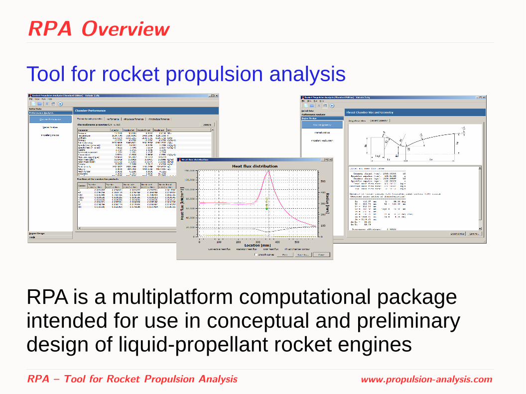
Tool for rocket propulsion analysis
RPA is a multiplatform computational package intended for use in conceptual and preliminary design of liquid-propellant rocket engines
RPA – Tool for Rocket Propulsion Analysis www.propulsion-analysis.com

RPA Overview
The motivation of RPA development was to...● Provide modern tool for prediction of rocket engine
performance at the conceptual and preliminary stages of design
● Capture impacts on engine performance due to variation of design parameters
● Assess the parameters of main engine components to provide better data for detailed analysis/design
● Assist in education of new generation of propulsion engineers
RPA – Tool for Rocket Propulsion Analysis www.propulsion-analysis.com
RPA Overview
Features of the tool:
● Steady-state analysis
● Simplified physical models and wide usage of semi-empirical relations
● Minimum of input parameters
● Rapid execution with accuracy sufficient for conceptual and preliminary design studies
RPA – Tool for Rocket Propulsion Analysis www.propulsion-analysis.com
RPA Overview
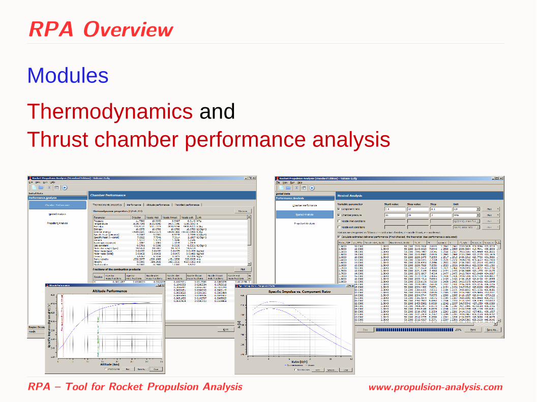
Modules
Thermodynamics and Thrust chamber performance analysis
RPA – Tool for Rocket Propulsion Analysis www.propulsion-analysis.com

RPA Overview
Modules
Thrust chamber sizing and Nozzle contour design
RPA – Tool for Rocket Propulsion Analysis www.propulsion-analysis.com

RPA Overview
Modules
Thrust chamber thermal analysis
RPA – Tool for Rocket Propulsion Analysis www.propulsion-analysis.com

RPA Overview
Modules
Engine cycle analysis and Dry mass estimation
RPA – Tool for Rocket Propulsion Analysis www.propulsion-analysis.com

Thermodynamics
Properties of reactants and reaction products ● Expandable thermodynamic data library based on
NASA Glenn thermodynamic database (also used by CEA)
● Includes data for such propellant components as (but not limited to): – liquid hydrogen H2(L), liquid methane CH4(L), RP-1, RG-1,
synthine, MMH, UDMH, methyl alcohol
– liquid oxygen O2(L), nitrogen tetra-oxide N2O4, hydrogen peroxide H2O2
● User may add own propellant components and products of reaction
RPA – Tool for Rocket Propulsion Analysis www.propulsion-analysis.com
Thermodynamics
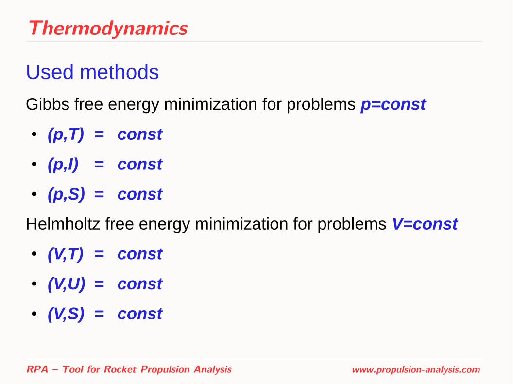
Used methods
Gibbs free energy minimization for problems p=const
● (p,T) = const
● (p,I) = const
● (p,S) = const
Helmholtz free energy minimization for problems V=const
● (V,T) = const
● (V,U) = const
● (V,S) = const
RPA – Tool for Rocket Propulsion Analysis www.propulsion-analysis.com
Performance Analysis
Assumptions:
● Ideal gas law is applied to all processes
● Adiabatic, isobaric, isenthalpic combustion in combustion chamber at injector face
● Adiabatic, isentropic quasi-one-dimensional nozzle flow for both shifting and frozen equilibrium models
RPA – Tool for Rocket Propulsion Analysis www.propulsion-analysis.com

Performance Analysis
Infinite-area combustion chamber
RPA – Tool for Rocket Propulsion Analysis www.propulsion-analysis.com
pinj = pinlet0 = pinlet
I inj = I inlet
S inj = Sinlet = St
vinj = v inlet = 0Subscripts:
inj = injector face
Inlet = nozzle inlet
t = nozzle throat
Finite-area combustion chamberpinj > pinlet
0 > pinlet
I inj > I inlet
Sinj < S inlet = St
vinj = 0 < vinlet

Performance Analysis
Ideal performance of thrust chamber
● Specific impulse in vacuum:
● Specific impulse at ambient pressure :
● Characteristic velocity:
● Thrust coefficient in vacuum:
● Thrust coefficient at ambient pressure :
RPA – Tool for Rocket Propulsion Analysis www.propulsion-analysis.com
I spvac = ve +
peveρe
I spa = I sp
vac−paveρe
C fvac = I sp
vac /c*
C fa = I sp
a /c*
c* =pc
0
vtρt
pa
pa

Performance Analysis
Delivered performance of thrust chamber
● Specific impulse in vacuum:
● Specific impulse at ambient pressure :
● Characteristic velocity:
● Thrust coefficient in vacuum:
● Thrust coefficient at ambient pressure :
Correction factors are obtained from semi-empirical relations [1]
[1] For more details see: Ponomarenko, A. RPA: Tool for Rocket Propulsion Analysis. Assessment of Delivered Performance of Thrust Chamber. March 2013.
RPA – Tool for Rocket Propulsion Analysis www.propulsion-analysis.com
(I spvac)d = ζ cζn I sp
vac
(I spa )d=(I sp
vac)d−paveρe
(C fvac)d = ζnC f
vac
(C fa)d = ζnC f
a
(c*)d = ζc c*
pa
pa

Performance Analysis
Additional options:
● Analysis of nozzle performance with shifting and frozen chemical equilibrium
● Optimization of propellant components mixture ratio for max delivered
● Altitude performance analysis, over-expanded nozzle performance analysis
● Throttled engine performance analysis
RPA – Tool for Rocket Propulsion Analysis www.propulsion-analysis.com
(I spvac)d
Thrust Chamber Sizing
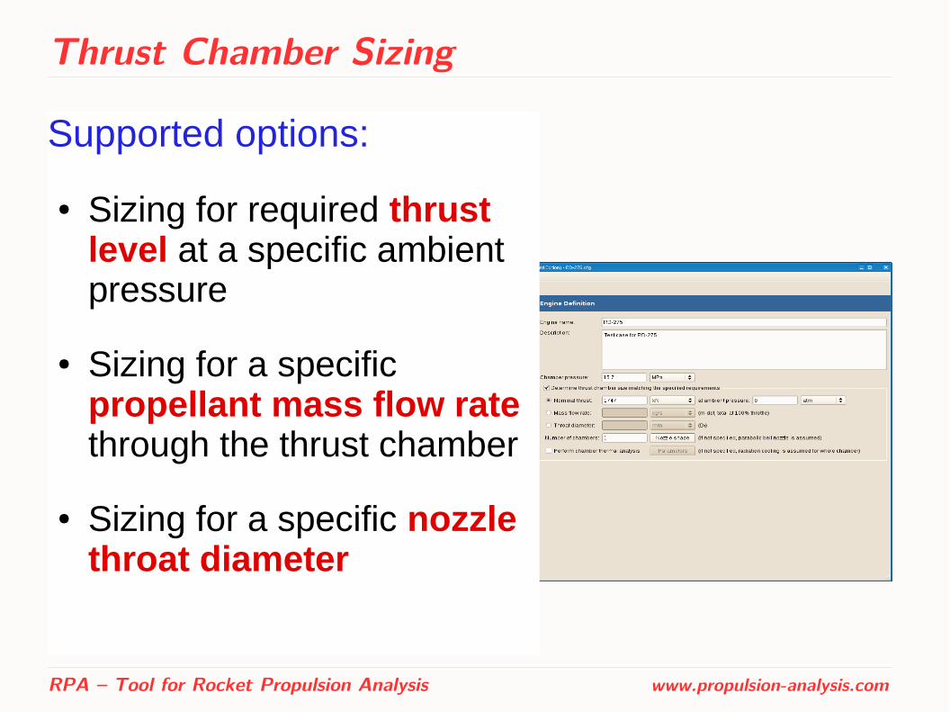
Supported options:
● Sizing for required thrust level at a specific ambient pressure
● Sizing for a specific propellant mass flow rate through the thrust chamber
● Sizing for a specific nozzle throat diameter
RPA – Tool for Rocket Propulsion Analysis www.propulsion-analysis.com

Thrust Chamber Sizing
Parametric definition of chamber geometry
The size of combustion chamber and the shape of nozzle inlet contour are defined parametrically by:
RPA – Tool for Rocket Propulsion Analysis www.propulsion-analysis.com
● mass flux at nozzle inlet or chamber contraction area ratio
● chamber length or characteristic length
● contraction half-angle
● relative parameters:
A c / A t
LcL*
R1/R tR2/R2
max
Rn /Rt
b

Nozzle Contour Design
Supported options:
● Cone nozzle with a specified exit half-angle
● Parabolic nozzle contour with specified or automatically assessed initial and/or exit half-angle
● Truncated ideal contour (TIC) with fixed expansion area ratioand nozzle length (design method: axisymmetric MOC)
● TIC with maximum thrust at fixed expansion area ratio (design method: axisymmetric MOC)
● TIC with maximum thrust at fixed nozzle length (design method: axisymmetric MOC)
RPA – Tool for Rocket Propulsion Analysis www.propulsion-analysis.com
Nozzle Contour Design
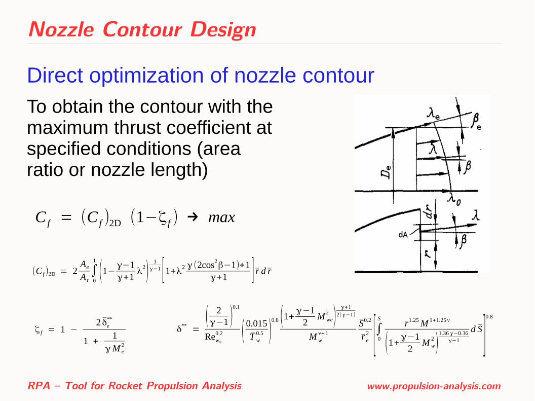
Direct optimization of nozzle contour
RPA – Tool for Rocket Propulsion Analysis www.propulsion-analysis.com
C f = (C f )2D (1−ζ f ) → max
(C f)2D = 2AeA t∫0
1
(1−γ−1γ+1
λ2)
1γ−1 [1+λ2 γ (2cos2
β−1)+1γ+1 ] r d r
To obtain the contour with the maximum thrust coefficient at specified conditions (area ratio or nozzle length)
ζ f = 1 −2 δe
**
1 +1
γM e2
δ** =( 2γ−1 )
0.1
Rew0
0.2 (0.015
T w0.5 )
0.8 (1+ γ−12
M we2 )
γ+12(γ−1)
M wν+1
S0.2
r e2 [∫0
Sr1.25M 1+1.25ν
(1+γ−12
M w2 )
1.36 γ−0.36γ−1
d S ]0.8
Thrust Chamber Thermal Analysis
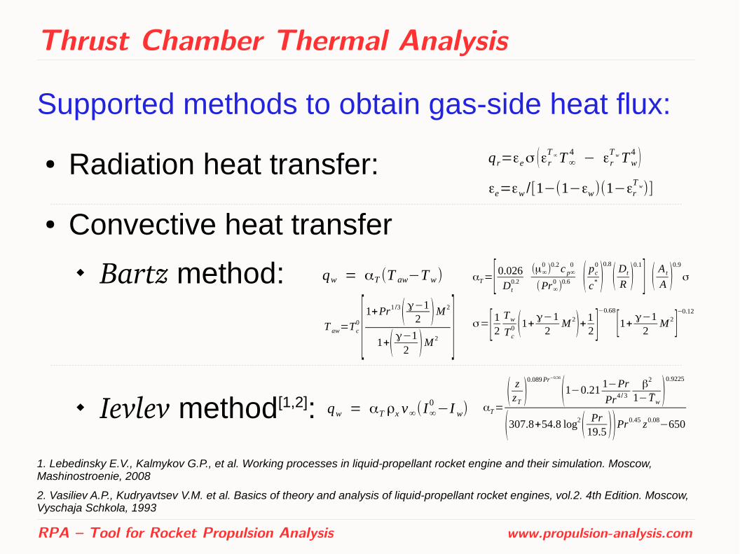
Supported methods to obtain gas-side heat flux:
● Radiation heat transfer:
● Convective heat transfer
Bartz method:
Ievlev method[1,2]:
1. Lebedinsky E.V., Kalmykov G.P., et al. Working processes in liquid-propellant rocket engine and their simulation. Moscow, Mashinostroenie, 2008
2. Vasiliev A.P., Kudryavtsev V.M. et al. Basics of theory and analysis of liquid-propellant rocket engines, vol.2. 4th Edition. Moscow, Vyschaja Schkola, 1993
RPA – Tool for Rocket Propulsion Analysis www.propulsion-analysis.com
qr=εeσ (εrT ∞T∞
4− εr
T wTw4 )
εe=εw /[1−(1−εw)(1−εrT w)]
qw = αT (T aw−Tw) αT=[ 0.026Dt
0.2
(μ∞0 )0.2c p∞
0
(Pr∞0)
0.6 ( pc0
c* )0.8
( Dt
R )0.1
] ( A t
A )0.9
σ
σ=[12 TwTc0 (1+γ−1
2M 2)+1
2 ]−0.68
[1+ γ−12
M 2]−0.12
T aw=Tc0 [1+Pr
1 /3( γ−12 )M 2
1+( γ−12 )M 2 ]
qw = αT ρx v∞(I∞0−I w) αT=
( zzT )0.089Pr−0.56
(1−0.211−Pr
Pr4 /3
β2
1− Tw )0.9225
(307.8+54.8 log2( Pr19.5 ))Pr0.45 z0.08−650
Thrust Chamber Thermal Analysis
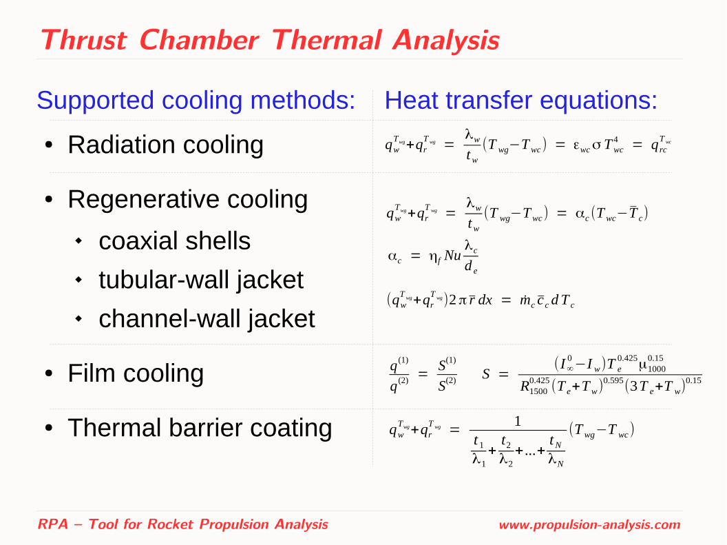
Supported cooling methods: Heat transfer equations:
● Radiation cooling
● Regenerative cooling
coaxial shells tubular-wall jacket channel-wall jacket
● Film cooling
● Thermal barrier coating
RPA – Tool for Rocket Propulsion Analysis www.propulsion-analysis.com
qwTwg+qr
T wg =λwtw
(T wg−Twc) = εwcσ Twc4 = qrc
T wc
qwTwg+qr
T wg =λwtw
(T wg−Twc) = αc (Twc−T c)
αc = ηf Nuλcd e
(qwT wg+qr
T wg)2π r dx = mc cc dT c
q (1)
q (2) =S(1)
S(2) S =(I∞
0−I w)T e
0.425μ1000
0.15
R15000.425
(T e+Tw)0.595
(3T e+T w)0.15
qwTwg+qr
T wg =1
t 1
λ1+t2λ2
+...+tNλN
(Twg−T wc)

Thrust Chamber Thermal Analysis
Regenerative cooling: coolant-side heat transfer
RPA – Tool for Rocket Propulsion Analysis www.propulsion-analysis.com
Nu = 0.021Rec0.8Pr c
0.4(0.64+0.36T c
T wc) for kerosene[1]
for liquid hydrogen[1]
for methane [1]
for other coolants [2]
Nu = 0.033 Rec0.8 Prc
0.4( T c
T wc)
0.57
Nu = 0.0185 Rec0.8Prc
0.4 ( T c
T wc)
0.1
Nu = 0.023Rec0.8 Prc
0.4
1. Lebedinsky E.V., Kalmykov G.P., et al. Working processes in liquid-propellant rocket engine and their simulation. Moscow, Mashinostroenie, 2008
2. Vasiliev A.P., Kudryavtsev V.M. et al. Basics of theory and analysis of liquid-propellant rocket engines, vol.2. 4th Edition. Moscow, Vyschaja Schkola, 1993
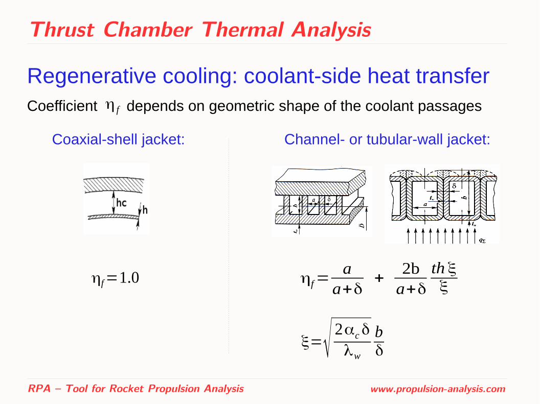
Thrust Chamber Thermal Analysis
Regenerative cooling: coolant-side heat transferCoefficient depends on geometric shape of the coolant passages
RPA – Tool for Rocket Propulsion Analysis www.propulsion-analysis.com
η f
Coaxial-shell jacket: Channel- or tubular-wall jacket:
ηf=1.0 ηf=aa+δ
+2ba+δ
th ξξ
ξ=√ 2αcδ
λw
bδ
Thrust Chamber Thermal Analysis
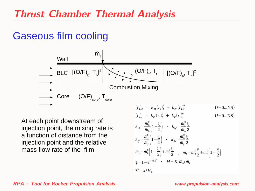
Gaseous film cooling
RPA – Tool for Rocket Propulsion Analysis www.propulsion-analysis.com
BLC
Core (O/F)core
, Tcore
(O/F)f, T
f[(O/F)b, T
b]1
mf
.
[(O/F)b, T
b]2
Wall
Combustion,Mixing
At each point downstream of injection point, the mixing rate is a function of distance from the injection point and the relative mass flow rate of the film.
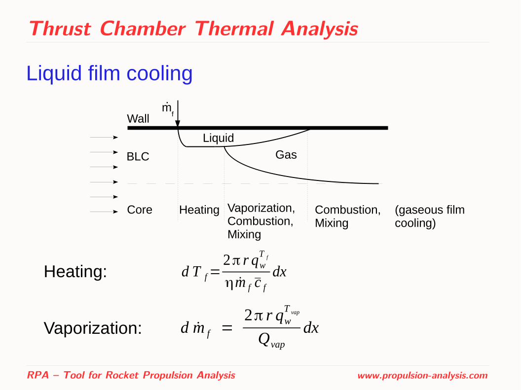
Thrust Chamber Thermal Analysis
Liquid film cooling
RPA – Tool for Rocket Propulsion Analysis www.propulsion-analysis.com
d T f=2π r qw
T f
ηm f c fdx
d m f =2π r qw
T vap
Qvap
dx
Heating:
Vaporization:
.
Core
BLC
mfWall
Heating Vaporization,Combustion,Mixing
Combustion,Mixing
Liquid
Gas
(gaseous film cooling)
Engine Cycle Analysis
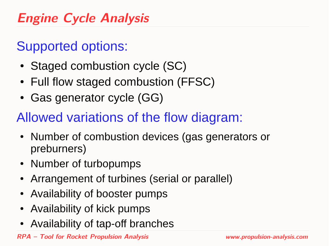
Supported options:● Staged combustion cycle (SC)● Full flow staged combustion (FFSC)● Gas generator cycle (GG)
Allowed variations of the flow diagram: ● Number of combustion devices (gas generators or
preburners)● Number of turbopumps ● Arrangement of turbines (serial or parallel)● Availability of booster pumps ● Availability of kick pumps ● Availability of tap-off branches
RPA – Tool for Rocket Propulsion Analysis www.propulsion-analysis.com
Engine Cycle Analysis
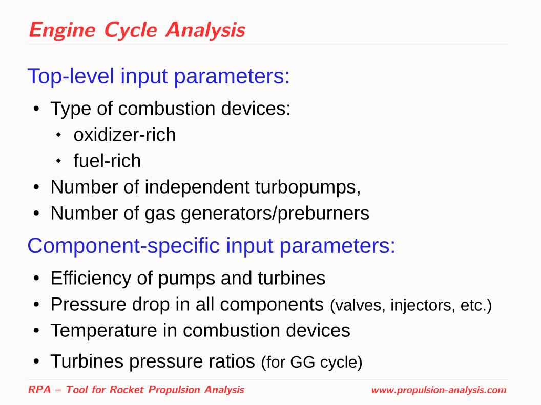
Top-level input parameters:● Type of combustion devices:
oxidizer-rich fuel-rich
● Number of independent turbopumps,● Number of gas generators/preburners
Component-specific input parameters:● Efficiency of pumps and turbines● Pressure drop in all components (valves, injectors, etc.) ● Temperature in combustion devices
● Turbines pressure ratios (for GG cycle)
RPA – Tool for Rocket Propulsion Analysis www.propulsion-analysis.com
Engine Cycle Analysis
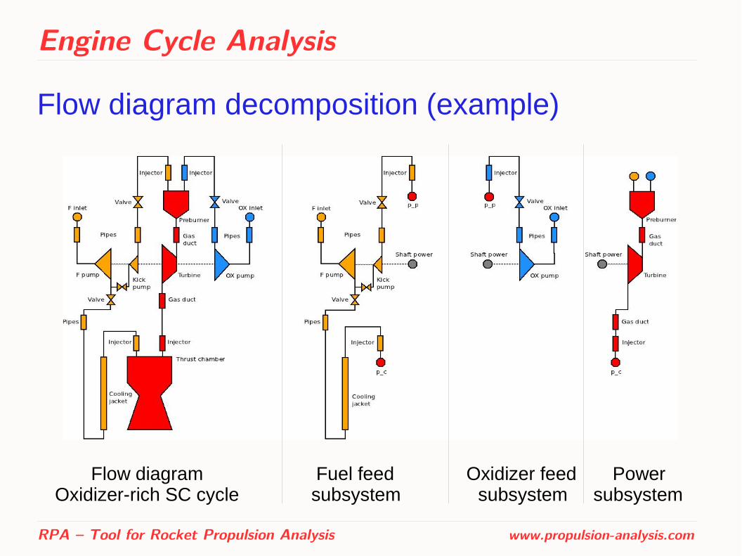
Flow diagram decomposition (example)
RPA – Tool for Rocket Propulsion Analysis www.propulsion-analysis.com
Flow diagram Fuel feed Oxidizer feed Power Oxidizer-rich SC cycle subsystem subsystem subsystem

Engine Cycle Analysis
Parameters of components
The pump shaft power:
The power developed by gas turbine:
The power developed by hydraulic turbine:
RPA – Tool for Rocket Propulsion Analysis www.propulsion-analysis.com
N p =mηp
( pout− pin)ρ
N t = mtηtγ
γ−1R0T t in
0 [1−( 1δt )
γ−1γ ]
N t = mt ηt( pout−pin)
ρ
Engine Cycle Analysis
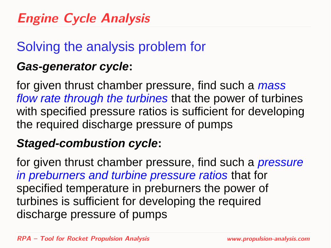
Solving the analysis problem for
Gas-generator cycle:
for given thrust chamber pressure, find such a mass flow rate through the turbines that the power of turbines with specified pressure ratios is sufficient for developing the required discharge pressure of pumps
Staged-combustion cycle:
for given thrust chamber pressure, find such a pressure in preburners and turbine pressure ratios that for specified temperature in preburners the power of turbines is sufficient for developing the required discharge pressure of pumps
RPA – Tool for Rocket Propulsion Analysis www.propulsion-analysis.com

Engine Dry Mass Estimation
● Based on the set of semi-empirical equations for each major type of engines: gas generator, staged combustion and expander cycles
● Initially developed at Moscow Aviation Institute
● RPA utilizes this method with slightly modified coefficients to better fit the available data on historic engines
● Results of chamber sizing and cycle analysis are used as an input parameters of engine weight estimation
RPA – Tool for Rocket Propulsion Analysis www.propulsion-analysis.com

Test cases
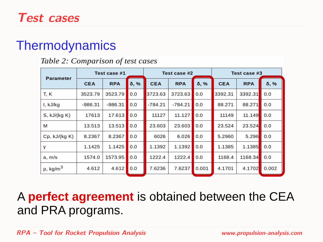
Thermodynamics
Comparison with NASA equilibrium code CEA has been performed for a large number of test cases.
Few of them are presented here:
RPA – Tool for Rocket Propulsion Analysis www.propulsion-analysis.com
Test cases
Thermodynamics
RPA – Tool for Rocket Propulsion Analysis www.propulsion-analysis.com
A perfect agreement is obtained between the CEA and PRA programs.
Test cases
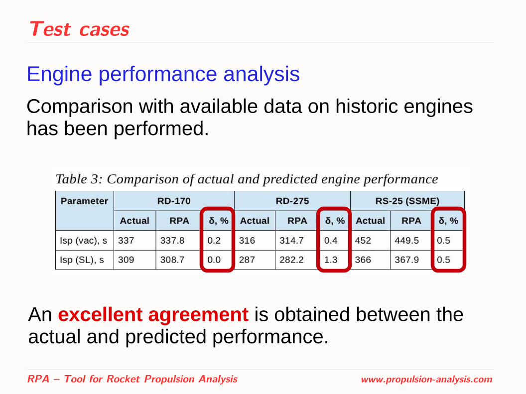
Engine performance analysis
Comparison with available data on historic engines has been performed.
RPA – Tool for Rocket Propulsion Analysis www.propulsion-analysis.com
An excellent agreement is obtained between the actual and predicted performance.

Test cases
Thrust chamber thermal analysis
Comparison with available reference data has been performed:
– SSME 40k [1]
– Aestus [2]
RPA – Tool for Rocket Propulsion Analysis www.propulsion-analysis.com
[1] Scaling Techniques for Design, Development, and Test. Carol E. Dexter, Mark F. Fisher, James R. Hulka, Konstantin P. Denisov, Alexander A. Shibanov, and Anatoliy F. Agarkov
[2] Simulation and Analysis of Thrust Chamber Flowfields: Storable Propellant Rockets. Dieter Preclik, Oliver Knab, Denis Estublier, and Dag Wennerberg
Test cases
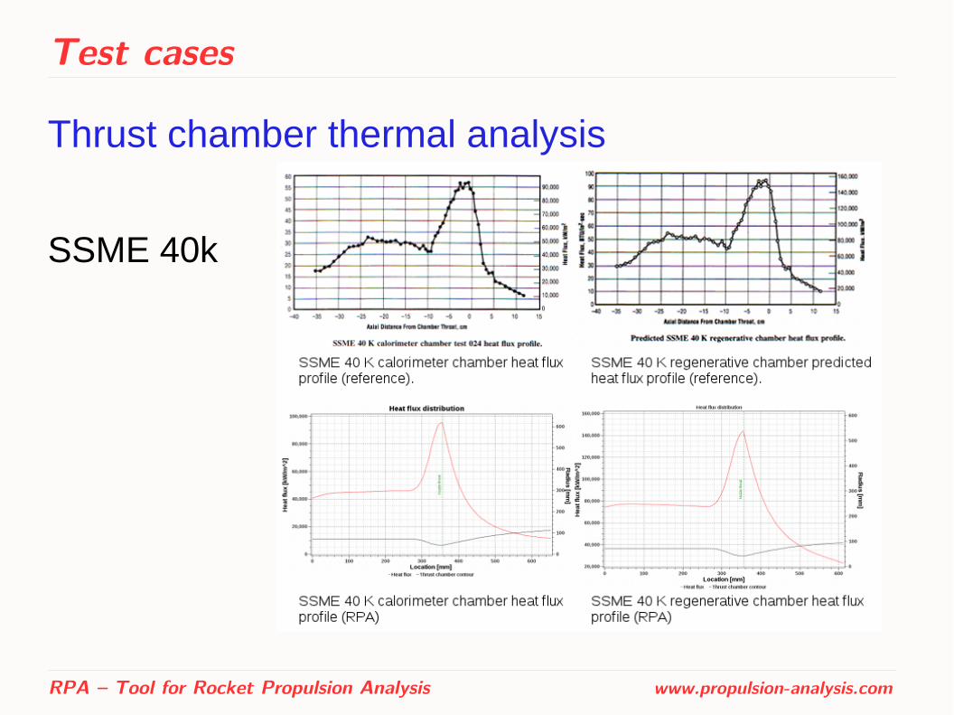
Thrust chamber thermal analysis
SSME 40k
RPA – Tool for Rocket Propulsion Analysis www.propulsion-analysis.com

Test cases
Thrust chamber thermal analysis
Aestus
RPA – Tool for Rocket Propulsion Analysis www.propulsion-analysis.com
Test cases
Thrust chamber thermal analysis ● Obtained good agreement is sufficient for
conceptual and preliminary design studies.
● Quantitative and qualitative differences in results can be explained by the following:
– RPA does not simulate fuel atomization and dispersion, as well as droplets burning
– The hot gas properties for thermal analysis are retrieved from quasi one-dimensional flow model
– The heat transfer is simulated in RPA using semi-empirical relations
RPA – Tool for Rocket Propulsion Analysis www.propulsion-analysis.com

Test cases
Cycle analysis and weight estimation
Comparison with available data on historic engines has been performed, including RD-170:
RPA – Tool for Rocket Propulsion Analysis www.propulsion-analysis.com
Obtained good agreement is sufficient for conceptual and preliminary design studies.

Future development
Future development of RPA ● Design of thrust optimized nozzle contour (TOC),
● Improved options for thermal analysis (e.g., support of jackets with bi-directional channels, support of BLC formed by injector, designing the cooling jackets, further validation including film cooling model),
● Improved options for modeling feed systems (e.g. estimation of pressure drop in a hydraulic components and efficiencies of the pumps and turbines),
● Support of additional engine cycles (e.g. expander cycle).
RPA – Tool for Rocket Propulsion Analysis www.propulsion-analysis.com

RPA - Tool for Rocket Propulsion Analysis
Thank you for your attention!
RPA – Tool for Rocket Propulsion Analysis www.propulsion-analysis.com