Royal Australian Navy Apprentice Training Establishmentboatregister.net/Library/Maritime...
65
i l ' l j_ ! 1 ' ........ ,I . · .. Royal Australian Navy Apprentice Training Establishment SHIP HUSBANDRY ' .· ' . i: ., . : . ! .. .( ... ·• , ,.
Transcript of Royal Australian Navy Apprentice Training Establishmentboatregister.net/Library/Maritime...

i l
' l
j_
! 1 '
........
,I
. · . .
Royal Australian Navy Apprentice Training Establishment
SHIP HUSBANDRY
' .· ~ ' . ~ i: ., . : ~ . · ~
! ..
. ( ...
·• , , .

Chapter 1
Chapter 2
Chapter 3
Chapter 4
lJhapter 5
HULL MAINTENANCE
Introduction General
CONTENTS
The Rules of Ship Husbandry Cleanliness Prevention of Malpractice Correct Use Correct Stowage Responsibilities of Officer and Senior Sailors Other Aspects of Hull Maintenance Precautions
EXM~INATION AND TESTS OF HULL AND STRUCTURE
Art. Nos ,
0101 0102 0103 0104 0105 0106 0107 0'1{)8 0109 0110
Introduction 020 1
General 0202 Examination 0203 Airtesting of Water-tight and Gas-tight Compartments 0204
ORGANISATION
Planning - The RAN System of Planned Maintenance The Master Index Maintenance Envelopes Check Off Maintenance Instructions Operation Books of Schedules Quarterly Report Forms The Dockyard Planned Maintenance Chart
CORROSION
0301 0302 0303 0304 0305 0306 0307 0308
Introduction 0401 Electrode Potentials 0402 Preventing Electro-Chemical Corrosion 0403 Cathode Re-actions 0404 Atmospheric Corrosion 0405 Preventing Atmospheric Corrosion 0406 Some examples of Corrosion Und.er Immersed Conditions 0407 Preventing Corrosion Under Immersed Conditions 0408
WA'rERTIGHT CLOSlJRES, VENTILATION AND DOMESTIC SERVICES
Intruductlon IVatert1gh t Doors, Hatches, Scuttles Chalk 'l'e c; t.
Vent1lat1on S,ystem:; Maintencmce of Vent llation System Cleanlng Vent1 lat1on Systems Ventilatlon Valves Defects and Fault s Domestic Services and Syst ems
0501 0502 0505 0504 050) 0506 0507 0508 0509

Chapter 6
TABLE
Chapter 7
APPElilliX A
APPElilliX B
APPENDIX C
APPElill IX D
Main Service and Sanitary Systems Hot and Cold Fresh Water Systems Cleaning Fresh Water Tanks Water Coolers Soil Pipes, Scuppers and Drains Main Suction Line
BOATS, WOODEN CRAFT Alill INFLATABLE LIFE RAFTS
Introduction Causes of Deterioration Shrinking, Warping and Splitting Structural Deformation Electro-Chemic a l Action Parasite Attack Rules for Maintenance Miscellaneous Maintenance Re ~uirements Inflatable Liferafts
Common Defects and Maintenance Re~uirements for Wooden Crafts and Boats
OTHER FITTINGS
Anchors and Cables Rigging Canvas Gear Terylene Saj ls Deck Coverings Woodwork Miscellaneous
Published Instructions for Maintenance of Hull and Fittings . ABR 5016
Published Instructions for Maintenance of Hull and Fittings. BR 31 & BR 3000
Publications referring to Repair and Maintenance of Hull and Fittings.
Forms e t c. in Current Use 7 Concerning Hull Maintenance.
Art. Nos.
0510 0511 0512 0513 0514 0515
0601 0602 0603 0604 0605 0606 0607 0608 0609
0701 0702 0703 0704 0705 0706 0707
------------

: ·-
CHAPTER 1
HULL MAINTENANCE
0101. INTRODUCTION
1. In the days of sail 11 Ship Husbandry 11 was the term used to denote all aspects of ship maintenance - hull, rigging, and weapons. As science and invention have made machinery, weapons and other equipments more and more intricate, the term 11Maintenance 11 has tended to become associated with the technical work of the specialist departments only. Many aspects of the equally important work of hull maintenance have become accepted as nontechnical and too often attention is paid to appearance, rather than material preservation.
2. With the realisation, during the 1939-45 War, or the enormous importance of Damage Control, came the appreciation or the need to treat hull maintenance on an equal footing with the maintenance of technical equipments. From that time the term "Ship Husbandry" has gradually been restored to the Naval vocabulary, to denote the various aspects of ship maintenance which are not specifically within the provinces of the Technical Departments.
3. Although a great part of such work is, strictly the responsibility of the Seaman Department, it must be stressed that the responsibility is shared by all departments and by every member of the ships company. Also the application of science to the problems of hull maintenance is beginning to introduce methods and procedures which preclude consideration of ship husbandry as an entirely non-technical activity; therefore instruction, training, practice, and experience now assume a greater importance than before.
0102. GENERAL
1. The hull of a ship provides a buoyant, and stable platform of suitable strength to carry the guns, aircraft, machinery, and other equipment with which it is desired to fit her. The problem of hull maintenance. is largely one of preserving this buoyancy, stability and strength, and is the concern of every man in the ship, officers as well as sailors. Firstly, because the size of the t ask demands the co-operation of all hands, as much by avoiding bad practices, as by direct participation in maintenance and repairs, and secondly, because everyone on board has a personal interest in making sure that the ship can withstand the stress of weather and action damage.
2. Although hul l maintenance is a big task, it can be made much easier, if it is organised methodically, if the knowledge of the experts on board is used for advice, and for training of the less skilled men, and if full and careful use is made of the mP.chanical aids provided. None of these are difficult if t ackled with common sense and team spirit; but it must be realised that hull maintenance is not merely a means of occupying unskilled labour. It is a vital, semi-skilled task calling for careful planning, sound training, and close supervlsJ.on. Because much of the work is laborious and repetitive, it is also a fruitful field for sound leadership.

0103
0103. THE RULES OF SHIP HUSBANDRY
Sound hull maintenance will only be achieved if the basic rules of ship husbandry are observed. These are -
(a) Immaculate cleanliness.
(b) Prevention of malpractice and slovenly habits.
(c) Correct use of equipments, fittings, and aids to maintenance.
(d) Correct stowage of equipments, fittings, and aids to maintenance.
(e) Provision of adequate and prompt maintenance effort - both for the prevention and repair of damage.
(f) Use of safety precautions.
0104 . CLEANLINESS
1. Apart from its effect on the health, comfort and well-being of the ships company, cleanliness plays a direct part in sound hull maintenance; not only does dirt make the visual inspection of structure more difficult, but, because it harbours moisture, it fosters deterioration of every kind.
2. The basic rule for cleanliness is that, if the awkward corners are kept clean the rest will almost look after itself: for example, in a passageway of a ship, if the tops of the carrier plates, fan trunks, and the spaces behind and under bulkhead fittings and hatch coamings are kept clean, it is a simple job to clean the bulkheads and decks, and to polish the brightwork; if, on the other hand, the difficult corners are dirty, no amount of brightwork and new paint will prevent the passage appearing dingy, while, at the first vibration or shock of gunfire, the dirt will rain down and the whole space will be filthy again.
Other points about cleaning techniques are -
(a) Always use the authorised cleaning materials and nothing else.
(b) Use clean materials, and when washing down, change the water frequently.
(c) Never use more water than is absolutely necessary: drying up afterwards makes extra work, and any moisture remaining will quickly set up corrosive cells .
: 0105. PREVENTION OF MALPRACTICE
1. It is regrettably true that a large proportion of the work of hull maintenance is caused by carelessness and bad practices of one kind or another: it is, therefore a positive part of ship husbandry to see that such practices are stopped .
2. A few examples are -
(a) Sweeping rubbish down scuppers.

::
0
0107
(b) Throwing rubbish down WCs; urinals, sinks and wash-basins ,
(c) Spilling water, oil, etc from buckets when carrying them to the gash chutes,
(d) Throwing cigarette packets, cigarette ends, and matchsticks on the deck instead of using the receptacles provided ,
(e) Stubbing out cigarette ends on wooden decks and linoleum ,
(f) Burning mess tables with cigarettes and irons ,
(g) Leaving milk bottles and cartons around the ship instead of disposing of them properly ,
(h) Dropping heavy articles down ladders thus breaking the treads and handrails ,
(j) Dropping hatch covers, thus damaging coatings and rubber joints ,
(k) Painting over grease nipples, t ally plates, and rubber gaskets .
(1) Standing on, or slinging hammocks from p i pes, valves and other fittings which are not designed to take such a load ,
0106 , CORRECT USE
The equipment in ships has been designed and developed for specific tasks; if it is used for any other purpose it will inevitably be damaged . For i nstance, if branch pipes are used as hammers their flanges will be distorted and they will be useless when they are most needed to fight a fire; similarly, if mechanical aids are used i ncorrectly or for the wrong purpose nothing useful will be achieved, the ships structure and fittings will be damaged, or the machine i tself will break down - in any event time and labour wi ll have been wasted , ext r a work and expense will be incurred in repairing the damage, and laborious manual work will again be needed while the machine is unserviceable .
0107 , CORRECT STOWAGE
It is easy to appreciate that gear left sculling around will deteriorate r apidly , collect dirt, and, soone r or later, will be lost or damaged , It is less obvious that equi pment which is stowed in its correct place, may also be deteriorati ng quickly, because it has been incorrectly stowed, for example
(a) Boats inadequa te ly chocked will become distorted and develope leaks,
(b) Canvas stowed away whil e it is still damp will rot and may start f1r es by spontaneous combustion .
lc) Be rthing wi res on the ir r ee l s may appear quite ship-shape under nea t can vas cove rs; but if the wires have not been properly dried and preserved they will rus t unseen and may be extremely dangerous when subsequentl y us ed .,
(d) To ensure safe handling and stowage of paint remover, the basis of which i s an extremel y vo lat i le material, all such paint removers are to be stored i n authorised screw topped containers only On no account should press-on lids be used .
Change No 2

0108
0108, RESPONSIBTLfTlES OF OFFICERS AND SENIOR SATLORS
1 , The responsibilities of various Officers for the maintenance of the hull and its fittings are laid down in BR 31 Queens-Regulations and Admiralty Instructions, Chapters 27 , 29 , 32, 54, 55, 56, BR 3000 Marine Engineering · Manual., Chapters 06, 08, 12, 24, 25, 26, 28, ABR 5016 Regulations and Tnstruct10ns for the RAN Chapters 29 (Sect i on TI) 41, 42, 43 and 54, ANOs and other publications, but nothing in these regulations absolves the . Departmental and Divisional Officers 0f their responsibility for ensuring that the1 r departments and par ts of ship are mainta1ned to the highest poss1.ble=: standard, and that defects do not arise through carelessness or abuse The same considerat i ons apply to senior sailors of every branch of the service .. Constant repression of the bad practices mentioned above is an integral part of the seni or sailors duty 'to ensure that order and regula.f'i ty are preserved in h is vicinity among those men, 0f whatever branch and whether on duty or not, who hold a rank junior to him'- see BR 31 Articles 1853 and 1854 .
2 . Off1c:ers and senior sailors also have a responsibility for ensuring that reasonable economy is exercised i n the use of ma'terials for maintenance, One means of exercising this economy 1s the sys tem of valuation allowances of consumable naval stores , Where these allowances are consistently or heavily exceeded, it is usually due to lack of planning or inadequate supervision Not only does this lead to a waste of money, but it generally impl1es that time and labour have been was ted, and poor results achieved,
0109 , OTHER ASPECTS OF HULL MAINTENANCE
1 . Althou gh the problem of hull maintenance .i. s mainly one of combatting corrosion, there are a host of items to be attended t o in addition to the main hull s tructure
2 The ~l c )st 1mportant of these ate t h.e wa·tertight closures: the doors, hatchr~s, ~ cut.tles, escape scuttles, square ports, valves etc which close off the holes provided for access and for the passage of pipes, cables, ventilation trunking etc It is on the effid.ency of these closures, and their ab t 1 i. t y to prevent interfloodmg rhar t he safety of the ship depends when hol ed
3 Fmal1y there are many items which play their part in the safety and effldenq· of the ship, her smartness and comfort, Such items as anchors and cables, re.plenishment at sea fittlngs, running and standing rigging, awnings and other canvas gear, wooden deck i ng, tiles and linoleum, dolllestic equipme11t s and systems, mess and cabin f u rniture e'tc . Their upkeep depends on regular examinat.ion and maintenanc•?;, c>:1rrect stowage and proper use, proper clean1ng methods, and t he a' 'o1dam e of bad practic.es at all times.
0110, PRECAUTIONS
1. As wi th all act1vlt1es on board sh1p, there are many precautions des i gned t ) try to avoid accidents and damage to the ship and her personnel, wh\ch -'He relevant to hull maintenance Tt is in his own interest that every man should make himself famil i ar Wlth them and discipline himself to obey them i.mp lici ty, however tri vial the -:x r:asion may seem ,
2 Some t eminders are noted below -
(aJ Ventilate confined spaces before entering.
Change No 2

0110
(b) Test air for oxygen content with a Davies Safety Lamp.
(c) Test air with an explosimeter before entering a space which has contained fuel or other volatile liquid.
(d) Obtain a gas free certificate for fuel tanks.
(e) Observe smoking rules when fuelling, ammunitioning and entering confined spaces.
(f) Beware of toxic fwnes when spray painting.
(g) Remove inflammable material before welding.
(h) Take care when operating heavy or armoured hatches.
(j) When working aloft attach tools with lanyards and draw "safe to transmit" keys.
(k) Use lifelines when working over the side.
(l) Use protective gloves when using paint remover.
(m) Use protective clothing and eye shields when working with de-rusting fluid, welding equipment, spray painting equipment, de scaling and wire-brushing machines.
3. Details of these and other safety precautions are published regularly in ANO's and are also contained in BR 3000, BR 31, ABR 5016, ABR 19, DNC Welding Handbook, ABR 4·

..,_
0203
CHAPTER 2
EXAMINATION AND TESTS OF HULL AND STRUCTURE
0201. INTRODUCTION
Unlike weapons and machinery whose condition can largely be assessed during operation from the evidence of performance and gauge readings, the state of the hull must be investigated almost entirely by simple tests. Regular inspection of all parts of the hull structure and prompt rectification of defects are essential -
(a) To ensure that it is free of major material defects - e.g. cracks, loose rivets, excessive corrosion - which would jeopardise strength, water-tightness and safety.
(b)
0202. GENERAL
To ensure that the prescribed measures for the prevention of deterioration and corrosion have been correctly applied and still retain their usefulness.
1. Visual examination of the hull structure by the specialist departments is a formidable task which is best achieved as a continuous process - taking a section at a time whenever operational conditions permit, making a thorough examination and recording fully in the relevant forms and books the results discovered. To make this task easier the RAN System of Planned Maintenance which is described in Chapter 3 was developed.
2. Because, by its nature, the visual inspection is a lengthy process which can be progressed only at infrequent intervals, it is most necessary that everyone, especially those responsible for particular compartments, should assist the specialist's task by taking every opportunity to inspect, maintain, and improve the material state of the hull.
3. Rounds by Commanding Officers and Heads of Departments provide opportunity to focus attention upon this aspect of departmental and ship efficiency.
0203. EXAMINATION
1. The equipment required for examination is not elaborate, and usually consists of a small chipping hammer, a scraper, a probe, and a powerful torch.
2. Because much of the work must be done in cramped almost inaccessible places and often in wet and dirty conditions, the use of an assistant to write down the particulars of an examination will greatly assist its speed and usefulness. His presence is also a wise safety precaution, especially in confined and ill ventilated spaces.
3. Before examination of a compartment, give ample warning to the responsible department so that preparations may be made to move items and stores which impede access and to make arrangements to safeguard valuable and att:c e. c~ive stores, delicate instruments etc.

0203
..•
4· Full examination of some areas necessitates the prior removal of fixtures,heavy fittings or equipments which may be beyond the capacity of the ships staff, or entail unacceptable dislocation of the ships operational routine. Opportunity to survey these, with dockyard or base staff assistance should be taken during refits, long self maintenance and mid cycle docking periods. (The procedure to be adopted to obtain d~ckyard assistance in these matters is similar to that requesting dockyard assistance in any other matter, and i s fully described in relevant ANO's).
5· Examples of such places, which must not be neglected because of the inherent difficulty are -
(a) Behind mess-deck furniture especially at the ship's side and in the way of scuttles.
(b) Behind the linings of bathrooms.
(c) In way of bulkhead boundaries, and along stringers in compartments .
(d) Beneath the deck coverings of galleys, bathrooms and heads .
(e) Under insulation, especially in cold and cool rooms.
6. Even though a complete survey of such places cannot always be made by ship's staff, sample examinations should be made at regular intervals to obtain evidence of the general condition, in order to decide priorities when opportunity and assistance become available and to enable early information to be given to the refitting authority on the probable extent of dismantling, repair and renewal that will be necessary when the ship comes in hand for refit .
7. What to Look For -
(a) Leaks and major material defects such as cracks, bulges, and distortions; areas of active corrosion •
(b) Rust spots, particularly on deckheads and crowns of compartments; these, usually are a sign of excessive condensation, but at worst indicate that the plates above are perforated.
(c) Scattered groups of rust scabs; these are serious because they cover pits of active corrosion. If they are not treated immediately further deterioration is rapid.
(d) Edges of deck coverings that lift easily: if corrosion is not already present it will soon set in.
(e) Cracking, bulging or discolouration of paint, deck covering, or insulation: these almost invariably denote the presence of rust.
(f) Surface stains on paintwork etc: these are usually caused by rusty water trickling or dripping down and provide useful clues to the discovery of leaks.
(g) Holes in decks and bulkheads where pipes, bolts, or cables have been removed and the holes have not been blanked.
(h) Items of equipment - suction pipes, valves, rod-gearing, ventilat ion flaps and valves which are liable to become inoperable
---------~d~u~e~-t~o~-~--------------------------------------------------~---------------- --·----·-

(i) Misapplication of paint.
(ii) Lack of lubrication.
(iii) Chocking or jamming by stores, cloths, waste or dirt.
8. Places Requiring Particular Attention
All places that are difficult of access for cleaning, drying and painting require particular attention e.g. -
0203
(a) Structures obscured by furniture, lockers, fittings, pipes, cable carriers etc.
(b) Areas near deck-tubes, cable guards, and bulkhead glands.
(c) Bottom sections of machinery space bulkheads and machinery seatings.
(d) Behind and below stowages for gear and stores.
(e) Plating behind protection bars or plates in cable lockers.
(f) Non watertight spaces behind and below WC pedestals, and urinals.
9· All places where water - be it from sea or weather, condensation, spillage or leaks - can accumulate or is almost continually trickling are prone to corrosion e.g. -
(a) Near scuppers, spurnwat ers, and washdeck valves.
(b) Tank tops, and longitudinals in machinery spaces.
(c) Junctions of near horizonta l stiffeners with near vertical plates, particularly where drainage or limbering is inadequate or has become choked with dirt and paint.
(d) Bays of side frames and deck plates below side scuttle.s.
(e) Plating and framing around the rudder post.
(f) Junctions of mushroom ventilators with decks.
(g) Sumps and save-alls.
(h) Bilccs, particularly those whic~1 contain pipe systems made of nonferrous metal.
(j) Ventilation trunld.ng which is subject to the ingr ess of spray or rain.
10. All places where the paint-work (or ot~er protective surface) is liable to abrasion or damage require fre quent inspection e. g. -
(a) Ships side in way of fenclering areas .
(b) The water-line at the ends of the ship.
(c) Ship's side in way of the anchors.
(d) The deck in way of cable-worki ng .
)

0203
11. Parts of the structure which are less frequently examined include
(a) Light plating of superstructure and bridge particularly near coamings.
(b) Uptake spaces and fan chambers.
(c) Beneath deck coverings.
(d) Behind special linings and insulation.
12. To improve safety efficiency or hab itability, those carrying out a hull examination should also -
( .- \ ~,. Ensure that limber holes, scuppers, drains and suctions are clear,
and that they are adequate for their task. (Alterations or modifications to these should be made by a dockyard or repair base, and the normal routine for A & A is to be followed).
(b) See that bilges, sumps, and save - alls :::.re kept clean and dry.
(c) See that paint work is not allowed to become too thick, (to minimise the fire hazard).
(d) Invest igate the cause of any mould, fungoid gro;·1th or excessive condensation discovered. A common cause of this is poor ventilation or air circulation which may be due to -
( i) Original poor de sign or arr~.mgement.
(ii) Incorre ct operation.
(iii) Unauthorised alterations of fittings and equipment which interrupt or deflect the e.ir -floVI.
(iv) Defective l a:::;ging of struc ture, pi_pes or ventilation trunks.
(e) Ensure that paint surfaces, which have been broken or damaged in the course of t he examination, are made good immediately.
13. At periodical dockings, careful examination should be made of the following parts of the hull and underwater fittings.
(a) Outer-bottom plating, particularly strakes along the water-line.
(b) Areas adjacent to sonar outfits.
(c) Areas near non-ferrous fittlngs such a s propellers, inlet and discharge pipes.
(d) Underside of keel, esr)ecia lly ne2.r the after cut up.
(e) Shaft brackl-") ts, rope guards, and eddy-plates,
(f) Protective covering of propeller shaftin:_;.
(g) Cathodic protection anodes and C.ielectric snields.
(h) Rivets or weldint_';' in way of t ank s cont ai r. :i.H@; liquid.s (e.g. FFO ) where seepage can g-ive indic.atlon of le aks.

0204
(j) Composition fairing of lap joints.
(k) Areas adjacent to bilge keels: ensure limber holes in bilge keels are clear.
(l) The physical condition of the underwater and boot topping paint.
Note - Intermediate inspections of particular or suspect items can be made by taking advantage of routine diving practices.
0204. AIRTESTING OF WATER-TIGHT AND GAS-TIGHT COMPAR~reNrS
1. To prevent the spread of flooding in the event of underwater damage, maintenance of the watertight integrity of the hull is essential. For instance, a hole only 2 in . square 20 ft. below the water-line will allow the entry of flood water at a rate greater than a pump with a capacity of 70 tons per hour can remove it. An equivalent area can easily be made up of the sum of a number of small holes, e .g . bolt holes, cable glands where equipment has been removed, leaking door and hatch joints, defective closures, defective ventilation etc.
2 . Absolute gas-tightness requires even stricter attention to the discovery and repair of small leaks.
3. The regular visual examination should discover many of the leaks but, in order to make quite sure that none have been missed, all watertight and gas-tight compartments must be regularly air- tested making use of the indicator test plugs and a special adaptor.
4· Detailed information about these tests and the compartments to be tested are contained in Hull Technical Maintenance Schedules, BR 3000, and relevant ANO's.
5· Briefly the method of airtesting is -
(a) Pressure Test
(i) Raise the pressure in the compartment to the specified level above atmospheric (Normally 2 lbs ~er sq. in. or 54 in. water gauge).
(ii) Leave for a period of time and by means of a gauge or manometer note whether the pressure drops, and if so by how much. This will indicate whether any significant l eaks exist.
(iii) Keeping the pressure up to the specified limit, search all
! t~.
the boundaries in adjacent compartments to find lerucs. A solution of soapy water painted on the boundaries will greatly assist this search . If a leak exists the soapy water will bubble.
(iv) After repair of the lerucs so found, apply a check test and if the pressure does not now fall more than a certain amount in a given time, the compartment is considered to be acceptably free of leaks. The figure for this fall of pressure depends upon the size of the compartment and upon relative temperatures, but a general standard is that _6 inch water gauge of pressure should not fall more than 2 inch in ten minutes.
0204
(v) If the check test i s not satisfactory, thE~ search and test must be repeated.
(vi) T:,_is method, using a ;:)o.sitive pressure within a compartment, unfortunately necessitates access to all the surrounding compartments and boundaries, and renders the search long and tedious and often incurs difficulty of organisation.
(b) Vacuum Tests
(i) An alternative to the Pressure Test is to use a negative pressure within t he compartment while men inside carry out a search for leaks. A sufficient partial vacuum can be applied very simply by means of a vacuum cleaner and the sequence of operations is the same as for the Pressure Test. Although not as efficient a s the pressure method, which uses a higher pressure differential, this test has certain advantages -
(A) It is much quicker because it obviettes opening a large number of adjacent compartments some of which may be "confined spaces 11 and require pr:i.or ventilation and testing.
(B) It permits the air-testir~ programme to be progressed under conditions which might prohibit the pressure method, and thus as sists in maintaining a better standard of water-tightness than if no te st was made.
(c) It is indepenclant o.f a low pressure air supply and can be carried out . 1 all ships.
(D) There is li ttle possibility of applying too great a pressure and thus over-stressing and distorting light structures.
(ii) There are however certain limitations to the vacuum test -these are -
(A) Men must not be shut up in compartments to which access is by manhole only.
(B) Searchers within a compartment must not be left too long v1i thout ventilation and a positive means of communication must be employed and maintained.
6. In both me t hods the. location of leaks is assisted by the fact that usually the escape of ai r is <J.udib le.
7, During air-test ing t,rreat care must be taken to avoid excess pressure - which may over-stress and distort light or weakened structures, and careful
watch must be kept for any unasual deflection or bulging; these should be controlled, if necessary, -by sl:wring. Such faults may be indicative of weakening by corrosion or the effect of some previous damage and their cause should always be investigat ed .
8. Apart from the more obvious sources of leakage previously indicated, other leaks less easy to detect may }·,ave to be tracked down viz -
(a) Leaking joints and glands of pipe systems.
(b) Valves not fully closed due to stiff operating gear or rod gearing.
(c) Defective rivets or caulking; either due to original bad workmanship or to structural strain during service.

0301
CHAPTER 3
ORGANISATION
0301 • PLANNING - THE RAN SYSTEM OF PLA...""'l"NED MAINTENANCE
1. The aim of the common planned maintenance system as used in the RAN is to provide -
(a) A standard system for controlling maintenance along sound and proven lines with the minimum of supervision.
(b) A central record of work completed, results of tests, and of alterations carried out on structure and equipment.
(c) A standard method of reporting progress of maintenance in ships and establishments.
2. The planned maintenance system in no way alters the responsibilities of officers as laid down in RI, BR 31, BR 3000, and departures may accordingly be made at the direction of the officers concerned. In such cases amendment proposals on Form A&--266-6 will be required.
/.H/~~-3. The system is based on a modern card index which contains a nwnber of cards giving a permanent record of each maintainable item of equipment. The index is contained in a cabinet consisting of a number of card carrying trays, or in a visible card book r/ . .1 . .:: ::0 L ; ~ -:r:.:J ; ; n. c. :_ the :nasJ~ el: index.
4· Bach card in the : ~mster i ndex has a related polyethylene envelope containing a variety or cards which give details of routine maintenance and provide a means for the responsible sailor to report details of maintenance and the results of tests carried out. This envelope, complete with maintenance cards and maintenance report card, is enclosed in an outer polyethylene envelope knovm as a "maintenance envelope", and is normally kept in a ~"o :..1:2 .-' "~:.:.wer filing cabinet.
5· The master index and maintenance envelopes are operated on monthly cycles and above, and at the commencement of each programming period appropriate envelopes are selected for issue.
6. Since a large number of important routines are carried out more frequently, daily and weekly check off maintenance instructions and report forms are issued to the leader of each maintenance party.
7. The three j_ t ;:;; : ::; -·
(a) Master index .
(b) Maintenance envelope.
(c) Check off maintenance instructions.
together comprise the working part of the system and. are fully described later in this chapter.
; ; ... .

0301
8. To support the system, and to as s:ist in compiling reports, making good lost or damaged cards, and in preparing amendment proposals, the following documents which are also desc r ibed later in this chapter, are also supplied-
(a) Key plans.
(b) Books of maintenance schedules.
(c) Quarterly progress report fo rms.
(d) Dockyard planned maintenance progress chart.
9. All documents associated wi.th the system are initially supplied by Navy Office. Replacement cards, envelopes and forms, with the exception of AS 3007 (Equipment Card) , are obtainable from SVSO on demand. Equipment Card AS 3007 is issued from Navy Offi ce comple t e wi.th equipment details.
r.-.; ~~" 10. Amendment proposals, For m .l!£:-:2062 , are t o be f orwarded to Navy Office through the administrative authorities. These will be considered and the ship or establishment informed of the action taken.
11. Reports required are -
(a) Quarterly by signal .
(b) Quarterly progress report forms are to be cc,mpleted in accordance with the instruction printed on the reverse side of the report forms cover sheet and forwarded directly to The Secr etary, Department of t he Nav,y, Navy Of:fi ce, Canberra.
12. When ships become due for refit, Ships Officers are required to include in their main defect list all items of the docky ar·d component of planned maintenance. The re levant card number only is to be quoted under the equipment title for each item and the a ssociated F'orm AS 2061Z, serial number quoted . /l'j 14-.Y
13. Defect recording and reporting procedure, although alli ed with planned maintenance, is applicable to all shi ps and establis~~ents and separate instructions have been promulgated in other orders. The prefix letter before the serial number on Forms A&-:206·1 Z for defects made good by ships s taff is to be strictly adhered tor~s "~lows ··
H. Hull
E. Engi neering
L. Electrical includ ing Weapons Electrical
w. Weapons .
The letters denote t he originating depart ment i:U1.d ot r1er prefixes are not to be used .
14. Report s of defective material or desiE:,'Tl are dealt with by using Form AS 2022 pro cedure. Thi s procedure is standard for all ships and establishments whetiier operating planned maintenance or not, and separate instruction detail the procedure.

0305
15. Starred items are included in the schedules. These are items for which the inspection, examination, and overhaul is mandatory. Naval Board approval is to be obtained before a starred item can be deferred.
0302. THE MASTER INDEX
1. The master index consists of a kalamazoo cabinet or folder containing e~uipment cards. Each maintainable item of e~uipment is represented by its own e~uipment card which carries full details of the e~uipment. Associated with each e~uipment card are auxiliary sheets. These sheets will , of necessity, differ with each department according to the details which that department desires to be recorded.
2 . E~uipment cards on issue from Navy Office have a strip on the lower visible edge which is colour coded to indicate when rout ines are due. The colour conforms with the colour code for maintenance cards shown below.
0303 . MAINTENANCE ENVELOPES
1 . Each e~uipment card has a re lated maintenance outer envelope containing a maintenance report card with the appr opriate maintenance cards enclosed in a smaller inner envelope .
2 . Maintenance cards are co l oured to indica te t he periodic i ty of the routine inspection and have t he relevant mai ntenance instructions posted on them . Colour definitions in use are as follows -
Periodicity Colour
Monthly Blue
Quarterly Yelh•w
Half- Yearly Red
Annual Green
Biennial and over White
0304· CHECK OFF MAINTENANCE I NSTRUCTIONS
The se are maintenance r outine s fo r which no pe rmanent record of completion is re~uired, and are i ssued i n sheet or book .form. The me thod of COI:Jpletion \V i ll be sto.ted on the appropriate shee t s or i.n t he books.
0305 . OPEIU.T I Oi'r
The r.:aster L1dex is scanned at t he begi nnj.ng of each pro,sr amming peri od to se lect t he mai nte nance enve l ope f or the work be ir4g pld.nned, 'rhese selected envelopes are t hen issued t o section l eaders who c:..rrange t o perfor m t h e m;:;,in tenance . Vfuen the specified maintenanc e is complete d , t h e report cards are fill ed i n and the envelopes returned t o the main tenance office. ;.\ny r e levant information i s then transcribed to t he mas te r index and the quarterly progres s report a nd t he returned cards are t hen replaced in the inner envelope which had been retained . The i nner enve l ope is then replaced in the outer enve lope and re t urned to t he fi ling cabinet dr awer.
I I ' •. )

, I 0306 \
0306. BOOKS OF SCHEDULES
These are issued to ships, establishments, administrative authorities and dockyards by Navy Office and contain the following -
(a) An index which lists all relevant equipments with schedule and card numbers.
(b) Maintenance schedules applicable to the ship or establishment. Each schedule bears an identifying number. When maintenance cards are lost, new cards available from SVSO can be prepared and the appropriate routines copied from the relevant schedule.
(c) Key plans are prepared in Navy Office for planning a satisfactory distribution of maintenance over the year. The key plan lists every maintainable item of equipment, its location, appropriate schedule and card number. All routines required to be completed are also shown.
0307. Q.UARTERLY REPORT FORMS
=- These are supplied to simplify the reporting procedure and consist of -
(a) Front cover sheet with instructions for compiling the report and a ~ table to be completed by ship or establishment showing how the
available man hours during the quarter were used.
·· ""
(b) An extract of the key plan showing all routines due during the quarter with a space :eft for recording man hours; a maintenance summary for each section, and a space for remarks.
(i) The manhours spent on planned maintenance is exclusive of monthly and more frequent routines for Hull, Engineering and Weapons Departments, and of daily and weekly routines for Electrical Department. These are shown separately in the space provided.
(ii) The estimated man hours to complete outstanding planned maintenance is to be calculated by adding together all the estimated times for routines not completed during the quarter.
(iii) The man hours spent on defects is calculated by adding together all the times shown on the submitted defect records Forms
_;AS_:_..:~. ,,y_, ~,-:
(iv) The estimated man hours to complete outstanding defects is to be calculated from all the outstanding defect records Forms ~~~-. 7 H- ,·~.7.
0308. THE DOCKYARD PLANNED MAINTENANCE CHART
This is a wall chart showing each routine of the dockyard component of planned maintenance, and separate instructions are issued for its use .
0401
CORROSI ON
ffi 0401. INTRODUCTION
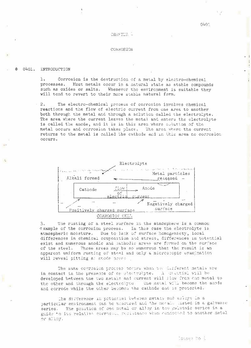
1. Corrosion is the de struction o f a met a l by electro- chemical processes. Most metals occur in a nat ural s tat e as s table compounds such as oxides or salts . Whenever the e nvironment is sui table t hey will tend to revert t o the i r more stable natur al form .
2 . The electro-chemical proce ss of corrosion invol ve s chemical reacti ons and the f l ow of e l ect r ic current fr om one area to another both through the metal and thr ough a solution cal led the e lectrolyte . The area where the current leaves the metal and enters the electrolyt e is calle d the a node , and it is in t his area where s~luti on of the metal occurs and cor ros ion takes place. The ares where the cur r ent returns to the metal is called the cathode and in this area no corr os ion occurs .
( ... -~ .. .. - , . ~ '····· .
Alkali f ormed
Electrolyte . . • ... ~ .. - .
Het,al part i cles ~------------'r~ ~E;~ s ed
flow _ Anode ""'-'-~,...-· J Cathode ---r-
~=-----~e ..,.1.e,._· 'c,__0t"'"'.i. ..... ·: i...,·. c-~".l:.r.:r.em___ 1
1
/_..../"' /" Negat ively ch~;ged I P · · sur face osltlvely charged surfac-~ ___.
CORROSION CELL
3. The rust ing of a st eel. sur face i.n the atmosphere i s a common example of the cor rosion process . In th:.t.s cas e the electrolyte is atmospher i c moi sture . Due to Jack of surface homogeniety, local differences in chemical c omposi t.i on a.r:d stress , diffe r ences i n pot e ntial exist and numerous anodi c a:1d cathodic a::·eas are fo:.-r:1ed on t he surface of the steel. 'l'hese areas may be so numerous that the result i s an apparent uni form r ust.ing of ste-=1 and 0:1.:l.y a mic r os :-::opic f::Xs.rc. im,t.ion will :reveaJ. p i tting a • m:odP a:·h' '~ .
rlih8 Sf;t.rr~e cc ·r~rosion prGces::-~ ") CC"J.!:'S \·lh ~:::n t,. ... : .. · :.i. .!_l t erent met.al::J are i n contact i:1 t h e -p r ese:1ce of e.n ::J.ec; r.:·o1yte. A ; c -r .:ctlt.ial will b e developed betv1een the tv.;o rnet.a1s and current ~rilJ :flci·J fro~m cne metal -to the other and through the electro1;rce . Une :ne·La 1. 'rl::.Ll become the ano0.e and cor r ode i·rh i le t he other becomes the cathode anci 1. s protected,
lhe di~ference in poten t 1al ~etwcen metsls a~a a!i~ys ~n a part i cular en·v-ironment can be m~o.~;·urc=d and the r:w:-.a.'· "' :.:i.sted in a g11l van~\. c s er i e s . The position of one metal or alloy i n th~ ga~v~nic series i s a guid~ to itG relatjv e cor r 0s 1 ~ ~ :.- c sl~tanc c when ~on~~c t 2d to another metal or s.J.1 oy _
- i I

0402
$ 0402. TABLE OF GALVN~IC SERIES FOR SEA WATER
1. When two metals on this table are in ccntact with each other in an electrolyte, such as sea water, the rnore anodic (most corrodable) metal in the series will corrode preferentially.
Most Corrodable (anodic or least noble)
Magnesium
Magnesium Alloys
Zinc
Galvanised steel or Galvanised wrought iron
Aluminium (commercially pure)
Cadmium
Aluminium (4% copper)
Mild Steel on Wrought Iron
Cast Iron
Chromium - Iron (active)
Ni-Resist
18-8 Chromium-nickel - iron
Type 304 (active)
18-8-3 Chromium-nickel - molybdenumiron Type 316 (active)
Lead - Tin solders
Lead
Tin
(cent from previous column)
Nickel ( active)
Inconel (act ive )
Hastelloy (active)
Brasses
Alur:1inium Bronze
Copper
Silicon Bronze
Copper-nickel alloys
Monel
Silver Solder
Nickel (passive)
I nconel (passive)
Chromium - Iron (passive)
Titanium
18-8 Chromium-nickel - iron
Type 304 (passive)
18-8-3 Chromium-nickel - molybdenumiron Type 316 (passive)
Hastelloy C (passive)
Silver
Gr aphi·te
Gold
Change No 1

0402
Platinum
Le ast Cc:r rodable
(Cat hodi c or mos t noble)
2. Oxygen also plays a part i n t he corrosion process. If the supply of oxygen at the cathode is increased, corros i on at the anode will be increased. Conversely, reduction in the oxygen will result in diminished corrosion at t he anode . Also in an other wi s e homogen:::ous system, oxygen rich areas will become cathodi c a nd oxygen de f icient are as anodic. The corrosion process, ther e f ore , invol ve s an e l E<t r ol yte , a cathode and an anode. It follows that any means of corroslon prevent ion must be aimed at one or more of the following-
(a) removal of the electrolyte . Pr0vided the metal can be kept dry no corr.osion wi ll occur . Th is can be done by drying the atmosphere t o prevent condensat i on or absorption of moisture on the surface .
Th i s is called 'dehumidifi cation'. Als o t he met al can be covered by a surf ace coat ing T..rhich is i mpervious to water. These are called 'lock-out' coatings ';
(b) stifling the anode reaction. Th i s is done by t he use of primers , cont-a ining pigmer.t s such a s z i nc chromat e whi ch inhib i t the anode r eact ion;
(c) insulat e th f' aiw de f r om t he ca tr,:-de i n b imetal li c sys t ems t o prevent current f l ow . An exe.mple of -chis is the use of insulating t ape be-r.',r e en t he fayin g surfaces of aluminiu.m and steel i n ships supe rs t ruct ures. Hhere insulati on is not feaslble avoid as far as pos s i ble ~o · 1pl ing together metals whi ch a r.=: far apart. on t he gal van i.e se~· .;. e s;
( d ) make the whole system cathodi ~ b y connecting the system to an E.nodP. wh i cb wi ll saeri fi c is.lly corrode. This is possible wher. the sy;.; t em i ~ t -Yta·:. .l.y i mmer s ~~ d i !1 1-::.n e l ect r olyt e, eg sea wate>, and i s ca :. l e C: ' c..c. c:':-::;JL·:· p:"c:.:::::tion ' , The same conditions e;an be a ctJ.e ved oy app l y ·1;1g a current ~u th e reverse direction to equal i se the c-·..:.rrsnt r'·:: rm•::d by the ::•)r rosi on cell. This i 2 call ed 1 1m:pressed. n<n·-::n~ cathodi c pr:)tection' ;
( e ) us12 ):' a met a l or al loy i n >rln ch t he co r r ,Js ion product formed at the a node i s insol uble 1s t he e lectrolyte and fo r ms an EJ.dhe:~ en~. i rr:oe:rv i ous f illn on t b e sur face of t he anode and stifles
f' · ~ - · T~. ·-•~ _i.~. '!c..~ ·J..';·~.-·c t .. ·r,_. e ·.J. c p_· of mat erials any •. '-.<:t" c .1C r rea.c t lcn. __ - _ . ~
"''~<"- '' -~'"' s t. &.J n :iJ: ss stee .. : ..; :.- :• ·.:·~Jpe:· a d cy s , eg altiintn i um, phosphor ~= sl'.l ~ G n ~r0n z~ ~ or c ~pp8r nic~~~ a~~ ~ J~;
·,·,·. -C·• ) . :1 'i": """" .-. + - n -~ ~, , 1.-, .: "• -.. ..·: - ~.· .. · ,_·_. J. -,.- •. '· : :.:-..iY •. • ,~:;:..,.. ,· . ...,·· ... ~ ;.::. <'.:l.,' •. .'t •J. \•i l l .l . p~· :_~--.;] ~"';J;5: .). { U -~-:.. \,.; 1.. cf. 'IVll - L ~~ ..!.- ; ~ • .I ........... - .......... ¥
s acrifici ally cor r~de thus pr . ~~ct ~n g the unde r lying metal
~ ·-J :.
(
0403
0403.
0404.
Typical examples of this are galvanising of steel, metal spraying with an anodic metal, zine rich primers on steel, and cadmium plating on steel; and
(g) use of non-metallic material, particularly plastics, which are replacing metals in many ship applications.
PREVENTING ELECTRO-CHEMICAL CORROSION
l. To arrest corrosion in a galvanic corrosion cell it is only necessary to stop the current from flowing from the anode into the electrolyte. This can be done by one of the following techniques.
(a) Paints and Coatings. Coat the anode, the cathode, or both with an impervious layer such as a he avy duty paint. This prevents the electrolyte from coming into contact with the metal so no current flows, and no corrosion occurs.
(~) Remove the electrolyte or rende r it non conducting eg by relJlacing salt -v1ater with pure fresh 'dater.
(c) Insulate the anode from the cathode eg use plastic between aluminium and steel. This prevents current from flowing and hence no corrosion can occur.
(d) Cathodic Protection. Apply a potential to the surface relative to another anode so that a current flows into both surfaces of the corrosion cell. I f a sufficiently high potential is applied the current at the anode will be reversed, and corrosion will stop. This is called cathodic protection because the entire surface being protected becomes a cathode. The potential can be applied by connecting the surface to be protected to an anode made from a metal which is more negatively charged than the surface to be protected. The protective anode corrodes away in time; this is called sacrificial cathodic protection. Zinc, aluminium or magnesium are used as sacrificial anodes.
2. Alternatj_vely an anode of any metal c an be connected to the negative termihal of a source of DC current. If the other terminal is in electrical contact with the n1etals to be protected, a current will flow which\ will overwhelm the current which was emi·tting from the corroding area of the metal and corrosion will cease. This is impressed current cathodic prote btion. Anodes made of lead-silver and antimony, or platinised titanium suffer negligable corrosion and can be used to transrr..it current for many years.
CATHODE RE-ACTIONS
At the cathode the current entering the surface of the metal can -
(a) Cause metallic particles to plate out cnto the cathode. If the cathode is part of a.n <;o..luminium s-cn:<ct·.lre, copper which may be dissolved in the electrolyte -...ri ll plate onto the surface and form the cathode of a more powerf~l corrosion cell.
(b) Cause oxygen and hydrogen in the \later t~) combine to form a strong alkali Hhich damage s some undervater paints. This is an important factor in selecting undervrater paints for ships which are to be given cathodic protection. Currant RAN underwater
Change No 1

0405.
0406.
0406
p:1ints do not suf:f'c :c ::':" ::;1':1 s~.~;-, attacks.
ATMOSPHERIC CORROSION
1. Unless ~oisture is pr e sent atmospheric corrosion ls purely chemical and is usually self stifling. However,.moisture will condense on a surface even at quite lcm hwr,idities. If any salt is present on +~ he surface it attracts moistu~e to form a film of electolyte which supports electrochemical attack.
2. Dirt on the surface, or rust fro~ previous corros ion, can cause condensation at lower h~~idities and can retain moisture in their structure . These fact~rs result in corrosion continuing when a clean well painted surface wouli suffer no corrosion.
3. Soot containing sulphur can form sulphuric acid which is an excellent electrolyte and which can cause very rapid local corrosion.
4. Inter-crystalline corrosion can occur in aluminium alloys having a high magnesium content. The magnesium is originally dispersed throughout the aluminiwn but in time it precipitates in the grain boundaries which then become anodic. Corrosion of the grain boundaries causes the metal to disintegrate very rapidly.
5. If a stress is applied to a metal which is prone to inter-crystalline attack the crevices on the grain boundaries will open and this will break any protective film of corrosion products. This can cause further acceleration of corrosion.
PHEVEN'l'ING ATMOSPHERIC CORROSION
1. Under fairly dry conditions a normal paint system provides adequate protection providing a primer of zinc rich paint or an inhibiting zinc chromate is applied to the metal surface. Any moisture which passed through the outer coats of paint will re-act \.J"i th the zinc rich primer, o:c- the ::.inc chromate, to form products which seal the surface and stifle further att.ack.
2. .~reas of high humidity need one of the following heavy duty systems -
(a) Coal tar epoxies.
(b) Sprayed aluminiwr, for decks and bilges.
(c) ilectro pla-.:.ed zinc for threaded components.
(J.) 5-i ~t dir galvanising for smal l non threaded components, eg ladd.(~rs,
guard-rail slips etc.
3. Such meta:i.s as monel, phosphor bronze, gun-metal, aluminium bronze, and alumir,j_uf;, aL .. oys which have a .low magnesi um content and contain r-.o copper, r e qu:;_re no protective coating because of their adherent oxide filn.
4. st~inless steel also ~as a good protective oxid~ fi l m in air, but most s t ainless steels are prone t o corrosion under water.
5. Chrome pJ a.ting and cadmi1.lm platir:g shouJ.d not b·2 used on 3teel i:n a marine enviro:nr;ent if stainless steel is available.

. ~
0407
0407.
0408.
SOME EXAMPLES OF CORROSION UNDE F: IIvUviEP.SED CONDITIONS
(a) Crevice Corrosion
(b)
Oxygen cannot reach the surface of the metal in a crevice as readily as it can reach· the remainder of the surface of the metal which is in contact vrith the electrolyte. Consequently a small anode forms in the crevice which then suffers rapid attack.
Impingement Attack
Metals used in salt water systems are selected because they form adherent oxide films under immersed conditions. Fast flowing water removes some of this film, leaving small areas of bare metal which are anodic to the surrounding oxide covered metal and which then corrode rapidly to form pits.
(c) Dezincification
Brass is made of zinc, copper and t in. Under immersed conditions the zinc is anodic and is corroded away, leaving a soft structure of copper and tin.
PREVENTING CORROSION UNDER IMr~RSED CONDITIONS
1. Normal paints are not very effective underwater because they are slightly porous and when they become impregnated ,,ri th water they cease to insulate the metal from the electrolyte. It is necessary to use a non porous paint such as an epoxy, or e. bi 1: uminous paint.
2. If zinc or aluminiw1: is included in one of these coatings, it helps to seal small breaks in the paint f ilm because it re-acts with 1 the bare metal to form corrosion products.
3. Cathodic protection can be used wherever a surface is permanently immersed, but it is no~ economic to protect bare metal. The bare metal is ' usually coated with a heavy duty pain~ which greatly reduces the current required to give protection. Cathodic prote9tion sto~s corrosion occurring vrhere there are any breaks in the paint film. [
4. In cooling systems, a coating of heavy duty pa:int would adversely effect the transfer of heat into the cooling wat er. Inhibitors are often used to reduce corrosion in such systems. Anodic inhibitors such as sodium nitrate or sodium chromate, form insoluable ferric salts which stifle any corrosion at the anode but they are too expensive to use except in closed systems .
Change No 1

CHAF.r.8H 4
COR110SION
G401 . INTRODUC'l'ION
1. Corrosion is the destruction of a metal by chemical or electro-chem1c~l agencies, starting at the suri\ .. ce . i'.:ost metals occur in a natural state as stable compounds such as oxides, and it is only by careful refining that they can be isolated as rel e.tively pure metals. •lhenever the environment is sui table they will revert to their more stable unrefined form.
2. Corrosion can occur by one, or a combination of the following reactions -
(a) Direct Chemical AttQck
This occurs ':!hen a c,etal i s freshly cut and is in contact with oxygen or other r e - act ive at;ents. Usually the m2tal forms a thin adherent film of corro s ion products which, in the absence of moisture, will protect the metal from further attack.
(b) Electro-Chemical Attack
.2lectro-chemical at tn ck occurs when a current passes from a metal which is corrodible into a conducting fluid. Conductin.;; fluids are called electrolytes. The current passing into tho electrolyte takes metallic particles with it, which usually combine with elements in the ele ctrolyte. '.Vhen t he metal is immersed in the e l ectroly t e the corro s ion products often form remote from the surface an<l are c urried awe;.y. If only a thin film ::Jf elc:ctrolyte is on the metallic surface, corrosion products will uswc:. lly form as a loosely a dherent film. Some metals form a protective film, but r;:any wi ll continue to corrode .
3. ·The current ·:vhich causes an e l ectro -chemica l type of corro s i on ca n be: produced in seve r a l 'NE..ys b:.tt the moEt import ant one are -
(a) ~tray Surrents
'rhese c a n be a ny currents which use the !1ull of a sh l~) an(i :1 n electrolyte ::1s a lon resist.c.nce ~) r!th e . g . if pcwer for ·;,ce! ldi c1,:·: ~ s
supplied from a jetty to ~ ship and t here is no low resistance e n.::.'t!'!i.n(; strap b ehc: en ~he hull c-2.nd t!'; <~ jetty, i t is I"J.Uite li k ~ l ~r tll'~t ' · .~''1'r''l1t '"l' l : Y-. o~ .C: ~ f'r·on ·t}·p 1Jl"ll t~·lrour"h. th .. p c' "'' '' 'i i ''' tf"T' :'th.:-.. c... :.., ,_.~A .- \ . • r II .... :: ' '-'"'-' . . 1..- -.l .. •.. l..=:t .. ~ · __. .__._, ,__... _ '"""' -- \_ .t. .l.
e l c: etro l y~ ,:· j to tb: :.:;ho .. e connec t ion of the ivelding set. It ·,:LU of ·.:: O·.J. ~ · :> e c :::J.se r s:.c id e l e c tro - c - ~ :.::~; J .-;<, 2- ttc.ci'- ·."here it pa...;c;e[> fron t ~·le hu 11 ~J t~r. e ,:r :.t ~.: r.. It :i :3 t ·· :·J r t~ fo rs i!:!~·; ort t~ nt to bon•.-.l ~ -¥
shi~) :v the shore ~:1hc ne ·v2r ar.y shu.!..""e pc\·1.:: r i s bc:·ing su pplied to a shij) o
~~~: ~C: !J·.: .. Je::: ~!.. : : : \·~t.3.l l~) :~ n ~~c n:.:..~~ ct ;;..!. t 1! :n ·.:.l e.:: t ::· ·:; J.y t t:.=: T~ (H: ::~~ ·i· ·.'::.11 be t ·:~· o c c) ~:.i'lic tini_; tr.:nj:~ n.:::. i'·: .... i ~ :~ 1 ··~ (.; ·:~ :r )r~~: ·,'il .... ..:.. :..e · .·.:.. · ;:~c r: .~~: ... .: -:.nt J t ·_lt: r· l .2 c. t ~:·l~· t €' c:::.c.sirt.. .. ; t l1 r:: :-:t ::-: t :~ l ~~: ~; .::.•:;.:;:~ _ -:.: c:: . .- : .~~ ~;c.: d :::.th a p.::;;; i t.LvB
el (~· c :..r:~ (:~ -.. 1 -~· :l~.L\_;c . i".'~e ~ ... .. ~~- ~~~ .-:. .J ,.:.. L·· .. ~_( ,;~ .- ~ :..; .:i ~ J. tert:·: to ·oa~)s into tt:c: ;~.-.l. ~· c ~ roj . :{tt=: ca.u::;ir.i. .~-r t:·1o r:. ~;-t:.( ·~l to become chaJ'(.:·r:d \·rith a ne ~-;o..tive
e ~ ~.-~ ::tr·i .~L:..l c !J. :-ir.:;e . T:J. ':: : .. o1~· . .t l'- ~- ::-; t:·\~~·!c· ~ ~: ·::f t i~:2S8 t~.vo te:·v:oLcies f' o ..
t ; ·.:... .. . ,· ~ .::.: :.

--
0402
If the two metals are in metallic contact and are also joined externally by a current path through the electrolyte, an electr ic current will .flow. It will pass from the most positively charged metal to the more negatively charged metal via the metallic path. Simultaneously a current .will flow through the electrolyte path from the negatively charged metal to the positively charged metal. This is called a corrosion cell . The negatively charged metal is called the anode and the positively charged metal is called the cathode .
CORROSION CELL
.,..,.- ....... . ~ .... ___ .....--_ _.. --.... .. ___ --· .... ___ ~ ELECTROLYTE ~ ·- -- · . .. . .... _ - -~ .__..,.. ....... _.~-~ . _ ... . __ . - ..... , .... . ,. ,.,.
--. · ~ .. ·, METAL PARTICLES
<.- - - . ~-- - - .. --- -- ~-- ,- ------ - > RELEASED . , ·- -, ALKALI FORMED ............ _. ·· .
E~CTRIJC:- ----~-] L--------------------------
CATHODE
POSITIVELY CHARGED SURFACE NEGATIVELY CHARGED SURFACE
4· As has already been explained an electric current passing from a met al into an electrolyte causes corrosion, so the anode of a corrosion cell will suffer corrosion. There is no corrosion at the cathode.
0402 • ELECTRODE POTENTIALS
1. The potential to which various metals wi ll be charged when in contact with sea water are given below .
Normal Electrode Potentials at 25°C .
Metal Normal Electrode Potential
Gold + 1.42 Least corrosive Platinum + 1.2 S:ilver + 0 . 799 Mercury + o. 798 Copper + 0 . 34 Bismuth + 0 . 277 Hydrogen + o.ooo Lead - 0 . 126 Tin - 0 . 136 Nickel - 0 . 23 Cobalt - 0 . 27 Cadmium - 0 . 402 I r on 0. 44 Chroniwn - 0 . 71 Zinc - 0. 763 Nangr:.:1e:::e - 1. 05 Al \L11 i ni ur;, - 1. 66 Sod ·~vJrt 2. 713 Mat,'!lesium - 2._3 8 PotassL un - 2. 92 T_-i ~- ":1 :1 :.'.m • · j J ) '] !~~ ;)] t :;.:;r-rOSl"'/8

2. If any two of the above metals are in metallic contact and are both in contact with sea water, the metal which is lower on this table v1ill suffer severe corrosion unless some form of corrosion prevention is being used.
3, The potentials given in the above table are the averag·e potentials to which the surface of a metul \vill be chat·ged when in contact with sea wc:ter. Some areas of the metal surface will be higher, and others lower than thi s potential.
4· The differences result from such things as -
(a) Variations in the structure of the metal due to welding or working.
(b) Variations in the speed of the electrolyte.
(c) Variations in the oxygen conten t of the e lectrolyte .
5· The result is that corrosion cells can be set up on the surface of a metal which is in cont&.ct with an electrolyte. We lds, heavily worked are::~,s,
and areas which cannot be reached by oxygen, will be anoC:es and will corrude, The rest of the surface is the cathode and does not corrode.
0403. PREVENTING ELECTRO-CHEMICAL CORROSION
1. To arrest corrosion in a galvanic corrosion cell it is only necessary to stop the current from flowing from the anode into the electrolyte. This can be done by one of the follovring tech..11.iques.
(a) Paints and Coatings. Coat the anode, the cathode, or.· both with an impervious layer such as a heavy duty paint. 'l'his prevents the electrolyte from coming into contact with the metal so no current flows, and no corrosion occurs.
(b) Remove the electrolyte or render it non conducting e. g. by replacing salt water with pure fresh water.
(c) Insulate the anode from the cathode e.g. use plastic between aluminium and steel. This prevents current from flowing and hence no corrosion can oc cur.
(d) Cathodic Protection. ilpply a potential to the surface relatJve to another anode so t hat a cu:crent flows into both surfaces of the corrosion cell. If a sufficiently high potential is applied the current at the anode will be r eversed, and corrosion will stop. This is called cathodic p:cotection bec~1se the entire surface be1ng protected becomes a cathode. The potential can be applied by connec ting the surface to be protected to an anode made from a metal which is more negatively charged. than the ::;urfttce to be pro t ected. The protective anode corrodes away in ti1:~e; this is called sacrificial cathodic protection. Zinc, a l uminium or rr. c'Lgnesium are us c~ d us sacrifici.al anodes.

--
0404
2. Alternatively an anode of any metal can be connected to the negative terminal of a source of DC current. If the other terminal is in electrical contact with the metals to be protected, a current will flow which will overwhelm the current which was emitting from the corroding area of the metal and corrosion will cease. This is impressed current cathodic protection. Anodes made of lead-silver and antimony, or platinised titanium suffer negligable corrosion and can be used to transmit current for many years.
0404. CATHODE RE-ACTIONS
At the cathode the current entering the surface of the metal can -
(a) Cause metallic particles to plate out onto the cathode. If the cathode is part of an aluminium structure, copper which may be dissolved in the electrolyte will plate onto the surface and form the cathode of a more powerful corrosion cell.
(b) Cause oxygen and hydrogen in the water to combine to form a strong alkali which damages some underwater paints. This is an important factor in selecting underwater paints for ships which are to be given cathodic protection. Current RAN underwater paints do not suffer from such attacks.
0405. A~~OSPHERIC CORROSION
1. Unless moisture is present atmospheric corrosion is purely chemical and is usually self stifling. However, moisture will condense on a surface even at quite low humidities . If any salt is present on the surface it attracts moisture to form a film of electrolyte which supports electro-chemical attack.
2. Dirt on the surface, or rust from previous corrosion, can cause condensation at lower humidities and can retain moisture in their structure. These factors result in corrosion continuing when a clean well painted surface would suffer no corrosion.
3. Soot containing sulphur can form sulphuric acid which is an excellent electrolyte and which can cause very rapid local corrosion.
4· Inter-crystalline corrosion can occur in aluminium alloys having a high magnesium content. The magnesium is originally dispersed throughout the aluminium but in time it precipitates in the grain boundaries which then become anodic. Corrosion of the grain boundaries causes the metal to disintegrate very rapidly.
5· If a stress is applied to a metal which is prone to inter-crys talline attack the crevices on the grain boundaries vrill open and this will break any protective film of corrosion produ_c t s. This can cause further acceleration of corrosion.

0408
0406. PREVENTING ATJWSPHERIC CORROSION
1. Under fairly dry conditions a normal paint system provides adequate protection providing a primer of zinc rich paint or an iQhibiting zinc chromate is applied to the metal surface. Any moisture which passed through the outer coats of paint will re-act with the zinc rich primer, or the zinc chromate, to form products which seal the surface and stifle further attack.
2. Areas of high humidity need one of the following heavy duty systems -
(a) Coal tar epoxies .
(b) Sprayed aluminium for decks and bilges.
(c) Electro plated zinc for threaded components .
(d) Hot dip galvanising for small non threaded components, e .g . ladders , guard-rail slips etc .
3. Such metals as monel, phosphor bronze , t,""l.lll.-metal , a luminium bronze , and aluminium alloys which have a low magnesium content and contain no copper, require no protective coating because of their adherent oxide film .
4· Stainless steel a lso has a good protective oxide film in air, but most stainless steels are prone to co rrosion under water .
5· Chrome plat i ng and cadmium plating should not be used on steel in a marine environment if stainless steel is available.
0407 . SO:tviE EX.ANPLES OF COllliOSION UNDER H'Ii:GRSEIJ CONIJITIONS
(a) Crevi ce Corrosion
Oxygen cannot re ach the surface of the metal in a crevice as readily as it can reach the remainder of the surface of the metal which is in contact vrith t he e l e ctrolyte. Consequently a small anode forms in the crevice which then suffers r apid attack .
(b) Impingement Attack
Metals used in salt water systems are selected because they form adherent oxide fi l ms under i mmersed conditions . Fast flowing water removes some of t his film , leaving small areas of bare metal which are anodic t o t he surrounding oxide covered met al and which t hen corrode rapidl y t o fo:em pits .
(c) Ile zincif ication
Br as s is made of 'Z.inc, copper and tin . Under immersed conditions t he zinc i s anodic and is corr oded. away , leaving a soft structure of copper and t in .
0408. PRZVEJ.,!TI NG CORROSION UNDER ll:lJ:C:SR:3l~: IJ CO~TJ I TI ON::l
1 • Norma l IJaint s ar e .not very effc·cti ve u.nd2rwat er because they are c:;lightly porous und when t!tey be cor:1c irrr;J r egnat ed with water t hey cease to insulate t he me t al f r .Jm t he ele:ctrolyt e . I t is necessarJ to use a non · .. or~:.1s ;1air'.t Sl_:ch as an e -r; oxy , or a b i t '...~minous paint t

0408
2. If zinc or aluminium is included in one of these coatings, it helps to seal small breaks in the paint film because it re-acts with the bare metal to form corrosion products.
3. Cathodic protection can be used wherever a surface is permanently immersed, but it is not economic to protect bare metal. The bare metal is usually coated with a heavy duty paint which greatly reduces the current required to give protection. Cathodic protection stops corrosion occurring where there are any breaks in the paint film .
4· In cooling systems, a coating of heavy duty paint would adversely effect the transfer of heat into the cooling water. Inhibitors are often used to reduce corrosion in such systems. Anodic inhibitors such as sodium nitrate or sodium chromate, form insoluble ferric salts which stifle any corrosion at the anode but they are too expensive to use except in closed systems.

J)J2
CHAPTER 5
WATERTIGHT CLOSURES, VENTILATION AND DOMESTIC SERVICES
0501. ~rRODUCTION
1. The term "Watertight Closures" is here taken to include all doors, hatches and scuttles in watertight decks and bulkheads and external covers for ventilation inlets and discharges.
2. Other watertight closures, such as bul~1ead valves in pipe systems and ventilation trunking, storm valves on soil pipes and scuppers, and glands for electric cables, rod gearing, telegraph shafting etc., are not readily accessible and remain the responsibility of the specialist departments.
3. Maintenance of the efficiency, operability and watertightness of these closures is as vitally important to the safety of the ship as is the structure itself; chiefly to restrict the spread of flooding and to be able to restore services by isolating sections of the ship in the event of damage.
4• Although maintenance of bulkhead valves and glands is the responsibility of specialist departments, this work and the incidence of avoidable failures can be very much reduced by obeying a few simple rules -
(a) Do not paint the operating spindles, threads or any moving parts of valves.
(b) Do not paint over lubrication points and grease nipples on valves or on bearings and bevel-wheels of rod geari ng and telegraph shafting.
(c) Do not paint the neck bushe s, studs or nuts of bulkhead and deck glands.
(d) Do not hang heavy weights, c.lothing or hammocks on any part of the valves, rod gearing, etc.
0502. WATERTIGHT DOORS, HATCHES, SCUTTLES
1. There are certain basic requirements common to all-
(a) Operation
(i) Never drop or slam them, nor close them on any obstruction; such action will cause distortion of some part or de.rne.ge : -,2 rubber joints.
(ii)
(iii)
---'-----------
Take care , when handling heavy articles, not to J.D.maee s:t.lls
or coarnings. \ . [ . .\'he r. closlnL;, apply clips lightly and e·re11l,'i il.i. ~ r cunJ ttl '2 _ door or hatch, t!ten t1ghten the dia[;ons.lly opposi.te ;_)a·u· s o l' clips unti.l the door cr ~,a teL lS pressed firmly ,') lJ to i t fl
soo.ting. lf.:3 vr.'?r ap,rly more fo :ec ~~ th £J.n i8 no(!ossa_r.;·; for CC''.TGctlJ c:dntained fitti11g:s , a:amw.l .f,n·ce is (:ni~. e sufficie :1 t s.nd t "l e use of me cho.nics.l a.H1s 'Jhoul c1 ot: I · ) ·r-o i.d~lnn.

0502
(b) Maintenance
(i) Maintenance should normally entail no more than regular inspection, operation and lubrL::ation of hinges and clips and cleaning of rubber joints and the faces upon which they bear. Solvents such as white spirit should not be used to clean rubber joints. Hard paint can be removed by rubbing the affected area with a piece of hard wood tapered to a blunt chisel point. A detergent solution should be used to clean grease and oil from joints.
(ii) As a guide for ships not yet prograrruned for the RAN System of Hull Planned Maintenance, the recorrunended frequency of maintenance routines is given below -
(A) Hull Technical Rou tine (Naval Shipwright)
Monthly
Inspect escape manhole s in the ships side and decks to ensure that t hey are in order for immediate use. Ensure that wheel spanners, or other opening appliances are in their correct stowage and securely chained . Replace irrunediately any that are missing.
Half-Yearly
Check that leather washers on door clips form an effective seal, and that sealing rubbe rs to doors, deck scuttles, hatches, escape hatches and escape and side scuttles are in good condition and free of paint etc.
Annually
A.1 Take chalk impressions of all rubber joints, pack out or renew rubbers as necessary. Check all doors, deck scuttles, hatche s, escape scuttles and side scuttles for distortion.
A.2 Check that indicator test plugs, where fitted in hatches and doors, have a leather washer and are screwed down.
A.3 Remove clips to manho l e covers, examine joints for deterioration. Clean, lubricate and replace.
Biennially
B.1 Examine Dexine seals on oi l- tight manhole covers for wear and de terioration. Renew as necessary.
B.2 Check al l deuJli~1ts fo r dis~ ortion. B.3 Check t hat keep chainu and drop-nose pins to
de <::.d li ~:;h t 2 are in po 0ition .
Monthl;;
M.1 ClP.an - ~'-~ J'. llE~ J.c· :: t e a:!.:i. wc;rkint; pr~rts of doors, 1:~ec ~: s c ·1tt ~e s, h r... ~ ·. c ··-: .\ s , ~ s :~ <.l p e s--:..: :.. :. _~ : ~s , J..ni sid~~
scuttles, exposed : a the we ath0 ~ . ~aE X~ 510

0503. CHALK TEST
0504
Half-Yearly
H.1 Clean and lubricate all working parts of doors, deck scuttles, hatches, escape hatches and side scuttles. Lubricate between deck working parts with PX 103 grease.
H. 2 Check that all clips are free and effective in operation.
H.3 Check that deadlight open position retaining pins are chained in position and all retaining catches to hatches, doors, and scuttles are in good condition.
(c) Besides the routine inspections, all users of watertight closures should be alert to notice faults and defects, which should be reported at once to permit the necessary repairs being undertaken as soon as possible • .
After examination or repair of defects, a simple test for correct seating can be carried out by -
(a) Coat with chalk the bearing edge of the coaming or other feature which bears on the rubber gasket.
(b) Close and lightly clip the door, hatch or scuttle; then re-open it for examination of t he chalk mark on the gasket.
(c) If all is correct, an even chalk mark should be evident all around the joint; uneven marking indicates that either the frame or the gasket require levelling. The chalk mark will also show whether the door is correctly aligned with its seat; if it is not, hinges and pins probably require attention.
0504. VENTILATION SYSTEMS
1. Good ventilation within a ship is necessary for the health, comfort and well-being of the ship's company, the preservation of stores and to a certain extent, the efficient opera tion of equipment; proper care and operation of the ventilation system is essential to maintain the quality and quantity of the air delivered and to ensure rapid closing down to the various NBCD states.
2. The following are the basic principles of ship ventilation -
(a) Fresh air is supplied by fan to spaces where men live and work.
(b) Foul, hot, oil-laden or damp air and noxious gases are expelled by fan from compartments where such conditions exist.
(c) Fan supply is usual ly as sociated with fan exhaust, but in some compartments, si tuatc::d near ·the wea{:her deck or subject to special consic'l.eration, it i s sometime s sufficient to provide natural supply or eL~aust .

0505
3. Although the basic principles are simple, the requirements of habitability, watertight integrity and NBC Defence introduce complications, such as -
(a) Air heaters and coolers.
(b) Watertight valves and associated gearing.
(c) Watertight and gas-tight covers at inlets and outlets.
(d) Flap valves to permit recirculation of air when the ship is closed down in NBCD states, or to conserve air-cooling capacity.
(e) Filters for various purposes . '
4· These refinements considerab~y increase the maintenance task for ventilation systems.
0505. MAINTENANCE OF VENTILATION SYSTEM
1. The majority of the maintenance does not require particular skill, but, to be successful, it does require good organisation and co-ordination; operations requiring the services of skilled sailors are carried out in conjunction with the Shipwright , Engineering and Electrical Departments as necessary.
2. The greatest hindrances to efficient ventilation are dirt and seizure of moving parts by paint or lack of lubrication. Dirt on the inner surfaces of trunking on heating and cooling elements and on fan blades and casings slows down the flow of air and reduces the volumes delivered - sometimes by as much as 50 per cent; seizure of moving parts seriously handicaps rapid closing down for NBCD purposes and thus jeopardises the safety of the ship .
3. It is also very important to ensure that orifices do not become masked or blanked by gear, stores, kit, etc., and that the designed flow of air within a compartment is not disturbed or deflected by adding or moving equipment without consideration of the possible effect on ventilation.
4· For ships which are fully documented for planned maintenance, details of examinations and routines for ventilation systems are set out in their hull maintenance schedules, but as a guide for ships not documented the recommended frequency of maintenance routines i s given below.
(a) Hull Technical Routine (Nava l Shipwright)
Annually
A.1 By removing t he sides of gas flap boxes -
(i) I nspect fl aps for corrosion, damage, or distortion.
(ii) I nspec t rubber sea t s for damage or deterioration.
(iii) Chalk t e st seats and flaps.
1·1 . 2 Chalk te::> t all hinged watertight cove rs .
1~·5 St:c: i p und e:x:arnine ventilation val ves in w8t compartments. Cl ean o.!;d l.ub ,-:-i;:; .·, tt:: th:r-: a J.::: :-:ni seatings.
{_;c;; ·: er _.}_ v ,· r.-:.: :dat ion t::cunking vrith low =r·~~ ·--·::~ :: t ::.., · : '1 t ~ .~ ' -· -~ -~:\ ~:r::rfaces c f selected

~.
0505
Biennially
B.1 Strip and examine all ventilation valves; clean and lubricate threads, seats and working parts. For weather deck components use XG 310 grease; between deck components use PX 103 grease.
(b) Hull "User" Routines (Non Technical and User Departments)
Daily
Clean the grease filters in galley ventilation systems by scrubbing in a hot detergent solution.
Weekly
W.1 Clear accumulation of water in trunking via drain plugs.
W.2 Grease hinges, swing bolts, and butterfly nuts of watertight covers.
W -3 Check that rubber seals of watertight covers are free of paint and grease.
w.6
Monthly
Check that wedges where fitted in place of swing bolts are secured by chains.
Clean flame proof gauges in ventilation trunking to magazines (where fitted) mortar rooms and flammable storerooms.
Dry out condensate stunps of air conditioning units and check that drains are clear.
M.1 Operate through their full range of valves and flaps j.n ventilation to magazines and mortar rooms.
M.2 Clean filters and grids of heating and cooling coils.
M.3 Lubricate one way gas flaps on we ather decks.
M.4 Lubricate and operate through full limits all watertight ventilation valves in wet compartments.
M. 5 Progress l.ionthly - ventilation trtmking, throughout. the ship to be blown t hrongh, and all grills, baffles, {;·auzes, etc. cleaned. All SJ :stems fans, banjo fittings, sirroco's etc. are to be checked and secu.rely f a stfmed. rffiC:9 markings are to be checl\:ed ani repa i::ted as necessary.
Half-Yearly
H.1 Lubricate all flaps, baffle spinc'l.Je s, swing bolts, butterfly nuts, sliding shutter s, in:licators and rod gearing.
H.2 Operate through t heir full motion all valves :1r.d f'L 0 1) :J in the complete vent ilc.tion ~yst(; ffi, (r,r ~ ~ !:_;·Elz il""!E: s c:rG ~L~·i ·~~~ monthly).
' t

0506
0506. CLEANING VENTILATION SYSTEMS
1. Dirt and fluff, loosely adhering to the internal surfaces of trunking, can be rAmoved by a vacuum cleaner or by blowing it out with low pressure air: the former is obviously the preferable method, because it avoids the risk of fouling surrounding compartments and their contents, but it cannot reach many of the less accessible portions without dismantling a large amount of trunking.
2. Whenever any ventilation equipment is removed or opened for examination or repair, opportunity should be taken to clean all trunking and internal fittings thus rendered accessible.
3. Before undertaking extensive painting of compartments, it is recorr®ended that ventilation trunking associated with them should be cleaned as thoroughly as possible, making use of all inspection covers, louvres, diffusers, etc., as access for the nozzle of a vacuum cleaner.
4• Blowing through trunking with low pressure air should be carried out progressively from inlet to final discharge, and requires careful planning to avoid dispersing the dirt over a wide area -
(a) Stop the fan.
(b) Close all the louvres and diffusers, except one orifice at the end, and gag relief valves.
(c) Secure a finely-woven bag (e.g. a mail bag) over this final openir~, to collect the dirt dislodged.
(d) Blow the dirt along the trw1king from inlet to final discharge by inserting a low pressure air hose in the inlet, louvres, inspection covers, portable sections, etc.
5· Precautions -
(a) Men employed blowing through ventilation trunking must wear facemasks (as for spray painting), as the fine dust can be lethal.
(b) However carefully it is done, it is practically impossible to avoid blowing some of the dirt into compartments, therefore it is recommended that this operation should be planned to take place just prior to a major cleaning or painting operation.
(c) To ensure that all joints and fastenings are properly replaced and secured after removal, it is r e commended that such work should be done by an artificer attached to the ventilation party.
6. Cleaning exhaust trunks carrying oil or gre a se -laden air is more difficult, but the;v c::.re usua lly protected by fine -mesh grids to filter out much of the oily dirt. Large diame t er trunks can be washed. down with water and detergent solutio~, but smaller one s can, at pre sent, only be cleaned by dismantling a large num1)er of sections.
7· Fittings within ventila tion sys tems qu:i.ck l y become choked, especially tho se passing oil or gras. se-J.aden air and t her c;fcr·e requil'e ve 1~y- fr,3quent cleaning -
(a) Wire-mesh grids at inlets to trunks, oar t ic,~larly :i n galleys and machinery spaces; those s i t uated high u~ ad in inB G •~ et< sit- ::_c
places ~10uld n~t he ~o =go~ten an1 n~ ~~~~ t 81.

(b) Elements and grids of heating and cooling equipment.
(c) Deflection vanes ('splitters') at sharp bends.
(d) Certain types of valves.
0507. VENTILATION VALVES
0509
To avoid restriction of t he flow of air, the valves fitted at bulkheads and decks to maintain watertight integrity, must be large and are usually of the sluice type. Their maintenance must ensure that they can be closed quickly and easily, and that, when closed, they are absolutely watertight; regular lubrication and operation of the valves and associated gearing, together with freedom from paint and dirt on working parts are the main essentials. Check that indicator plates are firmly secured and correctly indicate the state of the valve; indicator plates must not be painted over nor removed for cleaning.
0508 . DEFECTS AND FAULTS
1. Recurrent defects and difficulties of maintenance of components should be reported on Form AS 2022 (Report of Defective Material and Design).
2 . Inadequate ventilation of a compartment which cannot be cured by the elimination of defects, bad maintenance and mis-operation, should be reported on Form AS 1120 (Report of Environmental Conditions in HMA Ships).
0509. D011ESTIC SERVICES .drill SYSTEMS
1. The services here considered, and the materials at present specified for their pipes, are -
(a) Main service and sanitary systems: an alloy of copper, nickel and iron.
(b) Hot and cold fresh water services: copper.
(c) Soil pipes, scuppers and drains: galvanised steel.
(d) ~Sain suction line: galvanised steel.
2. Some simple rn2.intenance rules, applicable to all, are -
(a) Isolation valves: at regular intervals, operate the valves t hrough their full r ange of travel and lightly grease threads and spin:lles , ,Jhere val ves can be operated by rod- gearing from remote positions, the whole system must be worked and lubricated .
(b) Leaks are not only unsightly and. waste ful, but also cause cor rosion of adj acent structure and fittings; a lways report leaks to tlle responsib1e department promptly and accurately.
(c) Tallif:-:s on valve-hand whee l s must not be removed for cleaning; th~:y may easily be lost or renlaced on t he wrong valve.

.. ~.
0510
(d) Do not paint working parts of valves, lubrication points, indicator or tally plates.
(e) Do not hang heavy weights on pipes or valves.
0510. MAIN SERVICE AND SANITARY SYSTEJ,:S
1. The n<ain service provides salt water at h1e;h pressure for fire-fighting, magazine spraying, machinery cooling, bathroom ej e ctors and washdeck purposes; fo r sanitary purposes , the pr essure is lowered by reducing valves.
2. Marine fouling - ma rine growth in salt water pipes c an cause serious restrictions, loss of efficiency and damac;t: to valves. Its onset and rate of increa se can be checked by thoroughly f'lushi.n[S the system once a week using all available pumps. 'llElp wat er throut5h open hydrants at the extreme ends of the line for 10-1 5 minutes; c. ::ir<" rnl:6t be t aken that the limiting pressure is not exceeded. and t hat part s wo aL~;ne d by corrosion or erosion do not develop l eaks and cause flooding.
3. Erosion occurs when the flu id exceeds a critical speed which is different for each type of material. Bends and restrictions in pipes can cause local velocities to b e excessive, During design and building as many as possible of the se are ehminat.ed , but where they are unavoidable, attempts are made to minimi se maintenar-1cc and ~'epai:r· effort by fitting, for ins t ance, short readily accessible l e n gths o f pipe on th8 downstream side of bends, to simplify replacement.
4· Ero s ion of valves and seats occur3 mostly when valves a re only partially open and necessitates ~ d1sproport ion~te repair effort; whenever possible, valves should be either fully open or completely closed.
5, Bathroom ejectors are of t en fitt ed t() cilsch arge was t e water from bathrooms below the wate r-line and are ope r ate d by water from the main service. Incorrec t operation of the valvE~s can c ause flooding and erosion of valves and seats; ejec t ors r::ust not be l .:.:. i ·-t. runni ng u nne cessarily nor should v a lves be left 1 c.r·acked 1 op0n ::.~ 1 tLe mislaken hope that the sump will be kept dry - wat er will flow back dovm thc'l st.<ction ~lipe and cause f looding. The rule must be: pump out swnps whe a it 1s nE= ce ssary, then shut valves comple t e ly.
0511. HO'l1 AND COLD FR3Sii ·,·:A'r.::~R SYSTEKS
1. Scaling oc cu rs in h ot water pl 0les, par tiGular ly r:ear h e aters and calorifiers when hard wat e r from s:r,or·:" :is us E.: d; lts fornw.tion is rapid vthen the ten.pe rature of the water exc;,~ecis 16C°F ., the.:::-e fore thermostats controlling heaters shou ld not be set Lie:·her tl1an ·1 60°1-',
2. I n some dish -W8.::J:1i nL and .i.<::.o.:: nd l'J J:i:"clllnery, steJ.Y:l and water are mixed - .... 0-, . ' , . . t
to give temperd. t ures ao:Jv e ; vJ .i.', .2 st.ru:.r:;;,r i s fitto.::d in tne Ql scnarge o rer;:ove calcium caruone:.tt~ nnd otner •:iepos .i.. ts, F1 J c·:rs a nd mixing valves requ1re frequent c l eb.tJ ~rtf:~ to remo'h depo ~; i t e·d s--~a1e o
3· Jat:LH'Om fi tt ing s - m.Linse of t~:e ~;c i'~ ttir:£~3 1 ;,; r e::JpGnsible for c:n·.p~ ::J ,y.L1 ~g "' J.o.x· i;e an1uur;c; :::,f ;:-, .'3.ln T.E lV>:lC~- e ,··~_ rJT t ,-~L~"l1 c:m te ill spared fLD;:; J :.· . ..:r(~ J.:r~rpo..:.~t:tnt :;or·k ..
;:;,.: ... :·_ ...

0) 1 (L
(b) Swivel ty:9e shower-heads must not be forced 8.nd broken if they become stiff or seized.
(c) Taps, mixing-valves and pi pe s must not be used as strong-points for wringj_ng out washed clothes.
(d) Shower pipes mu s t not be bent to alter the direction of the water stream.
0512, CLEANING FRESH WATER TANKS
(a) Men to be employed in FW tanks must first be examined by a medical officer.
(b) Clean overalls and rubber-soled shoes, new brooms, cloths and l·uckets must be provided for use in the tan.l{s.
(c) The usual method is -
( i) \'/ash down the tank with 6 to 10 in. of residual water.
(ii) Pump this dirty water overboard.
(iii) Rinse with about the same am::mnt of clean, fresh water and pump it overboard.
(iv) W'ipe down and dry the tank.
(v) On completion and just before final closing, the tank must be inspected by a medical officer.
0513. WATER COOLERS
The cooling capacity of water coolers is limited and water from them must not be misused or wasted. Frequently the drains are choked by the dregs from cups and utensll fJ which have been washed under the cooled-water discharge; beside being ·,vasteful, the consequent flooding corrodes deckplates beneath.
0514. SOIL PIPES, SCUPPERS Mm DRAINS
1. Defects of these systems due to 'fair wear and t ear' are not common , but blockages due to misuse 2.re a ll too frequent.
2. Be cat.; st.~ the remedy usually nece ssita tes stripping and dismantling of the pipes , the introduction of filthy water and obnoxious smells into living spaces can seldom be completely avoided., and it is to everyone's advantage to make an effort to keep these systems clear -
(a) Remove s cupper ,_:; .r~t.t i ngs only whe n absolutely necessary.
(b) ::>weep dirt into dust.pan.s, not into the_ scuppers.
(c) Never pour grease or f at ty ·:;aste down Sr:>.lley drains.
(d) In the heads, us e only the toild p<:1per proviJed.
(e) Never throw matches and cigarGt t e ends int CJ urincLJ.E: , nor pour clirty water d.own ·.vc panG - soap, scr:Jbl)erJ and cle:ming cloths ;}Y'e a caus~.· of bloc~- < :.::~';-:; .

>.
0515
(f) Remove all rubbish lying about t he deck, especially near scuppers.
(g) Regular flushing of soil and urinal pipes through the connections provided greatly reduces fouling of them and thus lessens the frequency of routine dismantling and cleaning.
3. At every refit, include an item in the Defect List for 50 per cent of soil pipes to be stripped, cleaned, regalvanised as necessary and replaced.
0515. 1~IN SUCTION LINE
1 • 'rhe main suction line is the ship 1 s pumping main and runs through the greater part of the ship's length, with branches from it to compartments low down in the hull; at the ends of the ship it is usual to fit stand pipes to compartments to pe rmit the use of portable pumps.
2. Apart from care of t he valves, which is similar t o that for other systems, the only maintenance required is to make sure that the suction strainers at the end of each branch are intact and free of obstruction. Caps of stand-pipes must not be removed for cleaning.

0602
CHAPTER 6
BOATS, WOODEN CRAFT AND INFLATABLE LIFE RAFTS
0601 • INTRODUCTION
The basic rules of ship husbandry, correct stowage, cleanliness and correct use, discussed in Chapter 1, apply eq_ually to ship's boats and wooden craft.
0602. CAUSES OF DETERIORATION
1. The failure of structural members or serious leakage in boats and wooden craft is generally due to one or more of the following causes -
(a) Rot.
(b) Shrinking, warping and splitting.
(c) Structural deformation.
(d) Electro chemical action.
(e) Parasite attack.
2. Rot is caused by various fungi which feed on wood that is moistened with fresh water. It is the most serious and widespread cause of trouble in wooden craft and boats. The fungi cannot grow if the wood is too dry nor can they live on saturated timber. Rot can be prevented by regular inspection, adeq_uate venti:lation and good maintenance as outlined below -
(a) Ensure that all gear is thoroughly dry before stowing in lockers.
(b) Do not stow wet ropes and fenders in the forepeaks and stern lockers of power boats,
(c) Keep bilges free of water. This will also ensure that the floorboards and paintwork in power boats are not stained with oil, which is collected in the sump between the engine bearers, and is floated out if accumulated water in the bilges overflows into the sump.
(d) When power boats are inboard open seat lockers, take up portable floorboards, open up forepeak and stern locker to allow thorough ventilation.
(e) Clean out bilges ai: regulc.r intervals and ensure that li.mber holes in timbers are clear .
(f) Drv out the bilges thoroughly once a month and touch up bare woodwork.
(g) On each occasion of hoisting boats examine the l:YLlll for evidence of l<~a!-:age especial1y along the garboard se81Tls, around fastenings 8.Ild er.gine bearer bo lts n.nd at plank edges in clinker built boats •

:.- ""
CHAPT}l]R 6
BOATS, WOODEN CF.JlFT AND OO'I.ATABLE LIFE RAFTS
0601. INTRODUCTION
The basic rules of ship huaband.r.r, correct stowe.gef olea:nlinF.;Z8 .cr:1C. correct use, discussed in Chapter 1 r apply equally to ship 1 s boats 'll'Ki.
wooden craft.
o602. CAUSES OF DETERIORA'l'ION
1. The failure ·of structural members or serious leakage in boats a.n.3. wooden craft is generally due to one or more of the following ca11ses -
(a) Rot.
(b) Shrinking, wa:rping and splitting.
(o) Structural deformation.
(d) Electro chemical action.
(e) Parasite attack.
2. Rot is caused by various fungi which feed on wood that is moistened with fresh water. It is the most serious and widespread cause of troublP -· wooden craft and boats. The fungi cannot grow if the wood is too <icy nox· can they live on saturated timber. Rot can be prevented by regular inspection, adequate ven·cilation a.nd good mainten~-~,nce as outlined below -
(a) Ensure that all gear is thoroughly dry before stowing in lockers.
(b) Do not stow wet ropes and fenders in the forepeaks and stern lookers of power boats.
(c) Keep bilges free of water. This will also ensure that the flc.~or-boards an.d paintwork in power boats are not stained with oil, whic··: is collected in the smnp between the engine bearers, and is floa-~G~\ outif accumulated wat.er in the bilges overflows into the stunp.
I (d) When power boats are inboard oi)en seat lockers, take up porte.bl8
floorboards, open up forGpeak 8.nd stern lo1cker to allow thorough ventilation.
(e) Clean out bilge·s at regular:· intervals and ensure the:t. lilnbe:r· nolE<• in timbers are clear.
(f) Dry out the bilges tbo:L'oughly once a month and touch up bare woodwork.
(g) On each occasion of hoisting boats examine \the hull for evidence of leakage especi.a~ly along th.e garboard. seams, around fasteni::;::~ and engine beaJ:"er bolt.:> and at ple,nk edges in clinker built boats.
---------------
0603
(h) Keep all joints and seams in deck planking and cabin tops of power boats well stopped up to prevent leakage of rainwater into the hulL
\j) Rot is to be treated as a~ urdef.
0603. SHRINKING , WARPING AND SPLITTING
If wood is allowed to become excessively dry it will tend to shrink, warp and split. Any moi s t ur e, such a s rain, subse que ntly entering the crevices so caused , will encourage the growth of r ot fungi which will damage the hull and wooden fittings , Wher e boats are stowed on board or laid up ashore for long periods the fol l owing precautions should be observed -
(a) Boat covers shoul d be f i tted to prote ct t he boats from the full hea t of the sun , espec i ally in tropi cal climat e s.
(b) Partially fill the boats wi th water, preferably salt, at regular intervals and drain out after soaki ng f or a day or so, taking care t hat the bilges are well supported be f or e the water is put in.
(c) In spect the boat a t regul ar inte rva ls, keep any shakes and open joints which deve lop well stopped wi t h white lead and ensure that the paint coatings a r e in good condi tion before the boat is put into service.
0604 . STRUCTURAL DEFOFlli1ATION
Generally t his wil l occur only when boats are carried in davits or are overloaded . It can be prevent ed by attention t o t he fo llowing details -
(a ) ··Nhen lifti ng a boat ensur e tha t the sl i ngs are corr ectly fitted to avo id stro.ini Y!f.· t he boat i.n way of t he sling plate s .
(b) 'v'fuen crutching do•:vn a bo at, make certain it is cor rectly pitched , so that t he cru.tche s bear evenly on the hull. Copper strips are gene r a lly t acked on the keel or hull planking of boats to indicate t he pos it i on of t he crutches. Except i n an emergency never a ttempt to crutch a boa t down in another boa ts crutche s. Crutch pads are t ai lored to t he boat a nd may not su i. t a similar cr aft. If a boat has to be s towed in crutche s other t han its own, the operation must be ca r efully carrie d. out a nd adjus tment s made by inserting soft wood packin,<:_!: on t he to :tJ S of the crutches to ensure an even bearing over the entir e a r ea .
(c ) Jo not use a boat ln i ts stowage as a repositor y fo r l oo se gear nor allow l arge quantiti ,:; s of wa t e r t o r em.s. in in the bilges f or l ong peri ods , :such ov8rlouding vn ll strain and de:t'orm the hu l L
(~~) ,.,.~-:. ~ :: ;:;2.:::. ~::. ::.; :::. ·::;~ .::.. :: ~i~ . Ei te;;!por al'J ::>tov. age on de c k e;:13ur e t hat the ke cd is \·;e l l sw~ oor t e u on cb.ocks, e special.i .v- in ·:my ,) f conce nt r ated ·.-..e i ghts such c..s r~n{;l nc:s ; t}wt tllr:: b ilr;es 'J.J'·'; wel l ::mpported by : i gh l ows :end , i~~ :-, L cr ; e boac , th<1.t n.dditio:ta l S:.:tDp0rt :. ·· ~ ,rovi deci '.J~{ fi t.t ... r~{;· :J.hores 1).nder t ~~e I" llt! .·. ; .. : r ~~ .

(e) "ifhen cc~curi 11g a i:>J -1. t l'o r ~1ca J !-t c.! c.: :.c11 t.C:.!l!~<l . ...:; t <.Hvnc:r:, the ;3e ~~ ~J.r i.r.::::~· pencL:1nt~3 ElUSt not ue set up t:)(:; ~J~?"· ~..l or t}!G c rl~i-..~ h:::~: wi lJ. t.Je ;~orc o•l. i.:-:to th;-: l.:;ottora ~;L~n :', ln:; . In o:-J Em boa t. s V1 ,, :; ~n··et:.:'!·.:>r c>t::ci:-J:•; bct ·.-(s<: n t£1~·~ ;_;u r.l·.'! [.:. ~~ 1 t:: cl2..rnpn of the securing· p::;nd.:...n ts must. bt~. fi~t od.
an~l s•.:t UD taut.
0605. 3LECTRO-Ci·U;J"HCAL .ACTION
The effect of placing two dissirralar metals in sea water was d iscusced in Chapte r 4· In boats rro :.1re not so much concerned with the effect on metals but wi th the fact that cheui cals which attack tlw wood are formed in the sea water around the fastenings. Soft 2nd discoloured areas form aro Lmct the fastenings which become loosened and so ceuse leakage. This is called "nail sickness". Action ~·thich may b e take n to minirnis0~ this riefect is -
(a) Keep the bilges a s dry as p 0 Sf3iJ.'] t::O,.
(b) Keep the paint coating·s .i.n [-;'O Od c :· ~ ,..,
(c) Keep nail heads :.!.nd joints ·.vell stopped up.
0 606. P A11AS IT;~ Nl'':l' ,\CK
Boats anJ wooden craft which spen<l long per.i.ods a fl c)ll t, esp:~cL:;ll:y jr;
tropical ·;raters, aro lia'ol8 to c:..t tack l)y mr~rine wood boring par<:csit..~::;, t: .:··.v most fre c~ue ntly r.: nc.) tln tcrr:· d ·r_. e in;; -
(a) 'I'err:!dO ·;wrm . - wh c1 cl'l turmels into and hone;;rco rnrJG t.::, ,; •:10od. 'I'h -·u,:· at tac:cs are u::mal l;)' confined to ·::arm or tro piC:~_;_ ·:raters but ~.lv~ ~'!.a• ·
favourable c:ond1 ti;)ns ce.n occur in tem:per:.:.te 'l.'L•:L.::r·s.
(b) ·Jribble crs...iJ- -:. ~ tirr,j r:r:::.> :~'0•1t:•1 in ~.;. J l ·; . .::.:, .,; ::c;, ;·rhi c:', ;jj_::·G ;;r~ ::t ]_ !·:·,-;
t •.1.n:1eln in tht..: ··:;oo:J to ~.·c)~£:1:.::. cuv8 Lo!1e for itu::::l i'. ~~nc~at··~Jn ... :: .. ~q craft, ~.·11~1-ich HHl ~3 t 'be m.:~.J nt :l.i. n~.::d cor:1:plete un~~t ~.lnu.ariia/::f~d, i:..1 t :i(:: o: ~ ~~.:
~:; ertain metl1od of prev,~nt i.on ~ ~.iJ.i pping the 1JO:_i t a...~1d. d:t·y .ln.::,; ~J~li.: ~. :::._~·
a p<-~ riod of ·J~.j dc..J :Ol ·.r1ll :o.U e .. ny in.:t't:-=:tion.
coat huLLs <>..rs- -
(a) Prever1t 1e~1 -:ar;r=.~t i'ar t i.c,Jl: ...... ! "'
. ·. :) ~ · . ,_. ;"'
: C~. . ~ .; . ..,..._,_- ;_; · ::.~ r : t ,..:.
\C) 4~ -... ; ·,·~:. :~ \·': __ ·~:'7.-_· _;~ 'l~. J.J i , . , r .· ~
.:. -' ;:_< 1) L ... r _: c :··~ ;_:. .:~;.
0608
0608. MISCELLANEOUS MAINTENANCE REQUIR.EJ/[8NT~
0609.
1. Buoyancy Test. All pulling and sailing boats are to be tested for buoyancy every two years as r e quired by :~n and AI Chapter 55 ·
2. Care of Boats Equipment
(a) Boats Slings. - The pins of the shackles to boats slings and disengaging gear should be removed, cleaned and greased at regular intervals. Slings, bridles, disengaging gear and spreaders are to be landed for testing at each refit or after any repairs have been carried out on them by ships' artificers. The intervals between tests are not however to exceed those laid down in QR and AI as amended by cur rent ANO's.
(b) Steering Gear. - The sheaves , wires, knuckles joints, tiller and link mechanisms, kitchen rudde r gear and a ll other components , according to t he type of steering arrangements f itted, are to be lubricated weekly.
(c) Sling Plate Fastenings. - Whenever a boat is sent into the dockyard for refit or for repair after damage, an item is to be included in the defec t li st accompanying the boat, to cover the examination of the fastenings of all sling and steadying chain eyeplates .
3. Common Defects. Informa tion concerning defect s corrunon to and the maintenance requirements for, wooden craft and boats, is summarised in the accompanying table.
4· Composite Craft. 'l'he foregoing notes and the accompanying table are applicable to the wooden parts of craft of composite construction. The framing of such ve ssels is usually of aluminium a l loy and the main troubles associated with this material are caused by galvanic action or attack by strong alkalie s, such as caustic soda or washing soda. Likely trouble spots are in the bilges and in othe r pl ace s where water may accumulate to form an electrical link between the aluminium alloy and other materials . It is th..;refore necessary to keep all such structure clean and dry and t'o inspect it frequently to ensure that corrosion is not taking place. For Coasta l Minesweepers ( 'ron Class) full instructions are contained in the Hull Maintenance Schedules.
INFLATABLE LIFERAFTS
1. The maintenance of inflc. t:1ble liferafts and survival pa cks on board Iil\!A ships is the responsibility of the Executive Department and the work involved. i s carried out by sai lors trained by the Safety Equipment and Survival Tr.a_in:..ng 3chool. Deta i l.ed Oc)8r,:ltion and. m<d.ntenance i nstructions for the equi_:)tnent are g iven in EH 197 7 ( 1) ' Opcra!:ing <lr.d 1>1a intenance :{and book r~):C t h e 20 Man Inflatable Life raft I •
;2, c,1re is to ·oe t:1.k2n :.:rH:m wo rking ()rt a ::1d a r ou: d t:hFc l iferaft stowages ~: hat t!1~ \ct~~i;:;r-~ s t.Jf t · .. 1e li ft..:rafts 2nC 31 .1 . ._'\·-ival pf. ... ck:~ ~=-1 a 2e u0L: st.Ftined wi t h L~r~-.;c:..sr~, :>l. ·l." or .:.1ci :·l s, no:::- ma·L· k~) ~l r-:1t. ' ! p ·. :. i ~ ·~t , .::;.. r;. :l t ··;..ut s e c;.1rtng i. i3!1,)n7!.rC.s
~;:re not :::::n.J.·ed 01 cut.

,,
TABLE
Go=on J zfects a'ld J,\aintenanc:e Requirements for Wooden Crafts ar,d 3oats
-----·----··---- -----·----- - ··- ---.---------. I
' <: c t I Ca.J. se l Lik-= ly Trouble Spots ·--- ~-· ··-------'----·· --- -
!
,· J.'·: I;f_~·a ·i Je c c:.~ :) l rjo ;. t i r.. u a.l l j~ ~ 3.:.1 r ?ore and after peaks ( hog, c; ~·l.:.t i~) ~ l ~ ar:. ·;.: ng frames a~1d at foot o f : ·.: ·: .r: ]1'-=- .:.:.:.;:n:>.: cd ! bt::. l1~H; ad). 3e2.l:l she lf r.::Y >: tu:.7e and poor vt:: i ~ ·t;i l at:i.on. I
I
I I
an~ associated knees particularly if frarning is continu-=d through ciecl~.
Bilges p8.!'ticul'-1rly t:.ncler 1 .:.' l ats 1o~o·hc :re l. iu~)le :...Y'1l i3 i
I
laid. Struct•=e behind lining, pw1e lling,buoy~~cy tarilis, fuel and water t a.r:ks, cable lockers. StrJcture unde r bal last
I which has not bee r: cemP.nted in. Deck planking under
, winch beds, deck fittir~s • etc . Gaps in seaTJJs of
-··- · ··----· I
Detection
Brashness and brittleness of wood, in association wit~ sl:rinL::age across the the grai n. Darkening of varnished nembers. ! knife point inserted in directi::m o!' grain can be easily withd.rawn. Ab sence of ring when struck with a hammer.
! Prevention
1 ·;;eekly opening of peaks, 1 bilges and cabin 1 panelling ar.cl buoyancy
tanks to allow ventilation. Prevention of entry of rain water. Frequent cleaning and pumping of bilges.
--t deck planking.
.. : . ;: ir~g-, 2xcessi vely hot or dry Pla~dng, particularly in Nomally obvious by Stowage out of direct · ·:!< 1· . .-; and sto\·la,_«;e in sunlit¢1t or clin!<:er built boats. distortion, surface sunlight. Fortnightly .l · t ;.·i.n5· 1 in way of engines or Keels and ster:Js, weather cracks or leakage. ir:Jmersion in salt
exhaust. Prolon_sed decks, deckhouses. water or washing dovm s tovmge under dry St1·ucture in way of leads with s a lt water. con.'l i t b ns . of exhaust piping. Maintenance of
efficient engine and exhaust insulation and ventilat ion.
Cure
Removal of infected timber and replacement with a seasoned timber treated with copper napthanate or Wolman salt preservative before coating.
1-30 1): ::r o'P 1-''0 (1) c+
(1) 1-j
"'
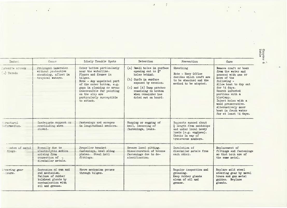
' I
:.r
~ ~-~-=;_:':'_"'__ I Cau'" . Lik•lY Troubl• Spot. D•t•ction Prevontion C=•
I ;·· J..~a s:i t e a tt'l ck Prolonged immersion Outer bottom particularly (a) Small holes in surface Sheathing Remove craft or boat , . ) ·r , without protect ive near the waterline. opening out to i'' from the water and ·. ·' .e.::-e:...o sheathing, afloat in Floors and frames in holes behind. Not: - Na~ Office proceed with one or
I
tropical waters. bilges . ( ) . dec~des wh~ch craft are more of the . b Curfs ~n surface t b h th d d th ·
I Note - Any unpa~nted part . 0 e s ea e an e follow~ng -of the outer bottom, e.g. exposed by eros~on. method to be adopted. Allow boat to dry out
. gaps in planking or areas (c) and. (d) Damp patches for 14 days.
-· .-,: .:::-uctural '·' .:. :~ rma tion.
I nadequate support or overloading when s towed.
I · ·:;sion of metal I Normally due to I
: ~ tj.ngs. 1 electrol:JtiC action
' tee ring gear t· i zure.
ari..sing from coru"lection of ·• d.~-:>similar me tala.
Corrosion of cam and rod mechanism. Failure of rubber bulkhead gla.'lds by contamination with oil and grease.
inaccessible for painting remaining in bottom Scorch infested on the slip are when remainder has portions with a particularly susceptible dried out on board. blowlamp. to attack. Inject holes with a
wood preservative . Alternatively moor boat in fresh water for at least 14 days.
Fastenings and scrapes in longitudinal members.
Propeller bracket fastenings, keel sling plates. Steel hull fittings.
Where mechanism passes through bilges.
Ho gging or sagging of keel, loosening of fastenings, leaks.
Severe local pitting. Discolouration of bronze f-astenings due to d.ezincification .
Supports spaced about i l ength from amidships and under local heavy loads (e.g. engines). Chocks in way of transverse members.
Insulation of dissimilar metals from each other .
Regular inspection and greasing. Keep rubber glands clean of oil and grease.
Replacement of fittings and fastenings so that both are of the same me tal.
Replace mild steel steering gear by naval brass and gun metal guides. Replace glands.
>-30 Pl::>' c'Pl f-J'tj <De+
<I)
li a-..\

0703
CHAPTER 7
OTHER FITTINGS
0701 • ANCHORS ANTI CABLES
Instructions for the maintenance of anchors and cables are contained in QR and AI and BR 367 Anchors, Chain Cables etc. The latter gives the details of and intervals for survey, heat treatment, tests and examinations.
0702. RIGGING
1. General guidance on the maintenance of rigging is given in the Seamanship Manual. More detailed instructions regarding lifting appliances are laid down in ANO's. The main points of pure maintenance as distinct from operating instructions, are summarised below.
2. Cordage. - Small cordage is supplied in coils which should be stowed in a dry, well ventilated compartment. Larger ropes are kept on reels and should always be thoroughly dried before stowing away. When reeling up ropes the opportunity should be taken to lubricate the reels.
3, Wire Ropes. - When being stowed away after use, wire ropes should be washed with fresh water to free them from salt, dried and then lightly coated with an acid-free lubricant, boiled linseed oil being the one most generally used . Vfuen wire ropes are being stowed on reels, the opportunity should again be taken to see that the reels are well lubricated. Instructions for the periodical examination of wire ropes are contained in QR and AI. RI and Hull Maintenance Schedules.
4· Guard Rails. - Guard rails other than PVC coated should be well coated with boiled linseed oil in accordance with Hull Maintenance Schedules. At the same time the bottle screw slips should be cleaned, worked through their full limits and greased; the bolts and pins from the heels of stanchions and stanchion stays should be removed, greased and replaced and any damaged or missing fittings should be repaired or replaced.
5. Boats' Falls. - Boats' falls made of cordage must be examined at least every three months and turned end for end or renewed as soon as they show signs of wear. The testing of wire rope falls is covered by the orde~s for lifting appliances.
6. Associated Fittings. - All fittings associated with rigging, such as the heel fittings of derricks and lower booms, sheaves and swivel blocks, rollers and roller fairleads should be lubricated regularly, in accordance with Hull Maintenance Schedules.
0703. CANVAS GEAR
Canvas covers of w~atherdeck ~i ttings a:e. gls.~ually ~eint;!; :replaced by nylon fabrics. The chlef canvas ltems remalnlng ln servlce are therefore awnings. The rules for their maintenance are as follows -
(a) On first spreading new awnings they \'J ill st reLch under the stress of the spreading arrangements and the ·wind. '.Phis stretching must be done gently and graduall;y, :i. , ,; • ! n~w awnings r,mst be slc.>.vly stretched ov~r a period of days .
;..
~ .
, .,.
0704
(b) Canvas gear must e.lways be t hor ouchly dr;y before stowing away. Small awning accessories ~-uch as gab l e ends should be stowed in the bags provided . Sail s wet from salt water should be rinsed in fresh water before dry l ng.
(c) Canvas gear requiring to be moved should be lifted and carried. Dragging along the de ck will t e nd to vrear and stretch it out of shape.
(d) Canvas gear must be kl~pt a s clean as possible as frequent scrubbing wears it out ,
0704. TERYLENE SAILS
Mark de sign limits f or all s a ils.
0705. DECK COVERINGS
1. Wooden Decks. -The chief points to be borne in mind when cleaning wooden decks are that they should be well swept before scrubbing, so that the dirt is not scrubbed in, that water should be used as sparingly as possible, and that the decks should be thoroughly dried before traffic is allowed.
2. The general practice is to use plain salt water with a bucket of fresh water and a cloth to remove salt splashes from paintwork and fittings. With wooden decks, as with all other aspects of ship husbandry, careful preparations and forethought can save a great deal of unnecessary work. For example, when painting a bulkhead or fittings above a wooden deck, it should be an invariable rule to lay a strip of canvas on the deck below the bulkhead to protect it f rom paint s pla shes and to Gtand the paint pots upon . Such simple precautions will produce a tidy finish and save many wasted. hours removing paint spots , I n the same way wooden decks should alway s be limed to protect t hem from gre ase bef o:r:-e ranging cable or wire .hawsers , Should, however, wooden dec ks be come very dirty or sta ined with oil or grease, the following measures can be u sed -
(a) A little sand may be scat t e r e d on the deck when scrubbing. Thi s he l ps to r emov<:! :i.ngr a int?d. d i .:.·t.
(b) The deck may bE ho1y st•.) ne d, hut t his should only be done oc ca s i onally a s i -1:. we ars the deck down, particularly whe r e it is made of soft wood.
(c ) lv'he n t ime i s not a·vaila bl e fo:-- holys toni ng, rl ecks may be scrubbed with a solution of washi ng sods. , soft soap and. cleans ing powde r or with a 1 in 300 sol u1, ion of caus t i c 30da i n ws.t er . ~;e ither
treatme nt i s as e f f ec ti<I G as bv ly37on ~ :l{~ and any solution containing soda i s de~3true"L ::.. ': <'< ·J f ::-a.J..ntwor l: and very harmful t o aluminium alloy s , Steps mu s t t he r e f o.:·e be t aken to pro t ee t t hese surfaces and t o r 2move an,y sp l ashes 1--l.t one :-) .
(d) Oil and grea se st ai. n ·.~ OYJ ·:-:ood.s n d<?. c ks c;hou ~d be coatEd. with a rnixture of lirHe : ln , ~l f _ .... ~· ~:::~. wc:d~Gr v:":1:Lcl1 abso :r:·b s the o i_L a ncl ~rea38 ·
\';'hen dry, the l iil;e s!·: u u ~~ C!e :::c r'ul: .·.i r; ff <md more :..r,p1ied i f necessary. 'l'be t T t:> <'.tE:P n ~. ·!.::-: or < .' e.!:' f 2:~:t1 vt': whe n cond itions allow t~a mixture to ~~ y .

-,
3, Steel and Aluminium Decks . Painting schemes for exterior steel and aluminium decks differ for the metal concerned and whether or not non-slip properties are specified . The relevant schemes are given in ABR 19/65 as also are the paint systems for internal metal decks, where it is laid down that they should be painted . The preparation and subsequent maintenance of
0705 4~
painted metal decks is the same as for the other metal structure , Where ~ internal decks are left bare, the only maintenance required is to keep the abrasive tread strips in good repair and the decks themselves clean, dry and free from corrosion , To save labour in keeping the decks corrosion free, full use should be made of the mechanical aids provided . Because of their specialised requirements aircraft carrier flight decks have their own painting schemes which are given in ABR 19/65 .
4. Abrasive Tread Strips . Abrasive tread strips and adhesive are naval store articles and the strips are simply maintained by replacement , In areas of heavy traffic they are laid ~in apart and in other places 6in apart . Where the deck is heavily pitted the initial preparation and laying of tread strips calls for dockyard assistance . On decks in good condition the procedure is as follows . The deck i s first swept clean , mechan i cally scaled if necessary and power 'wire brushed The surface should next be degreas ed and freed from old adhesive with a mixture of equal parts of naphtha and whi te spirit , The surface should then be pa i nted as in ABR 19/65 . The backing is then peeled from the tread strips and they are pressed firmly into position and the edges are sealed with a bead of adhesive ,
5 , Tiles . Experience has shown that vinyl tiles ar e superior to linoleum and they are now being fitted in new ships and where existing linoleum has to be replaced . They are supplied in a range of approved colours and are not to be treated with gum shellac for colouring or surfacing .
(a) Cleaning . The floor should be swept free of dust and grit with a soft brush . Sur face dirt which will not brush off should be removed with a cloth damped wi th warm water to whi ch detergent has been added in the approved ratio . Loose water should never be applied and floors that have been wiped wi th a damp cloth must be thoroughly dried . Obstinate marks may be removed by the careful use of . a blunt scraper or the fines t grade steel wool . Cl eaning powders , coarse abrasives, strong caustic soaps etc . , must not be used .
(b) Polishing , The best resu l ts are obtained by coat i ng the tiles with plastic polish . Subsequent maintenance consists only of wiping with a damp cloth , If, aft er some months, the polish shows signs of wear , it can be patched where necessary . Ins tructions for applying the different proprietary brands of plast i c pol i sh are issued in ANOs and manufacturers i nstructions . Where plastic polish is not applied, wax or wax emulsion polish should be used . Wax polish must be buffed by hand or with a polishing machine at the time of application . Wax emulsion polish dries with a semi-lustre but can be buffed to obtain a high gloss .
6 - Carpets . The maintenance of carpets calls for thei r correct treatment when new, cleaning by the approved methods and taking steps to equalise the wear over the whol e surface .
(a) New carpets tend t o ' fl uf' . The 'fluf' cons is ts of short wool fibre s which do not r each the base of the carpet and are only a sma ll proportion of the surface pil e . As much 'fluf' as possib~e should be allowed to remain in the pile as this hastens the felt1ng proces s , v1hich increases the wearing qualities To avoid tmn<:'cessary
Change N0 3

0706 .
070q ,. ' -~
loss of wool vigorous brushing of new carpets should be avoided and vacuum cleaners should be used with moderation .
(b) After the first month or two of use, carpets should be swept daily with a soft bristle brush and should be thoroughly cleaned with a vacuum cleaner once a week . · Carpets should be swept in the direction in which the pile lies and the last stroke of the vacuum cleaner should be in that direction . Vacuum cleaners give their maximum efficiency with a slow movement. Where brushes are used they will of course raise dust, but the practice of damping with tea leaves or damp sawdust is forbidden as this adversely affects the colours. Small rugs must not be shaken or beaten harshly against a wall or over a line as these practices loosen the hem and damage the fabric.
(c) To reduce wear at doorways and between furniture, carpets should be turned around every six months . Re-arrangement of furniture may also redirect traffic and help to equalise wear over the whole surface .
7 , Bathroom Deck Coverings . The policy for bathroom decks is to fit white unglazed ceramic tiles on the cork filled latex underlay in ships where the weight can be accepted. Where the weight cannot be accepted the decks are covered with vinyl-tiles . All types of deck covering should be cleaned with warm water and a mild soap . On no account should abrasives or strong detergents be used . Heavy scrubbing should be avoided .
WOODWORK
1 . Salt water is used for scrubbing bare woodwork. Sand may be added to remove ingrained dirt but should be used with caution when scrubbing the woodwork of boats as it is liable to be washed into the bilges where it is difficult to dislodge . Scrubbing with salt water and sharkskin produces the best finish on bare woodwork . Whichever method is used, to achieve best results, surplus water must be wiped off after scrubbing and the woodwork dried as quickly as possible . Soap should never be used as it leaves the wood greasy and may yellow it .
2 Polished wood should be washed with fresh water and dried or polished with furniture polish .
0707. MISCELLANEOUS
l , Stainless Steel and Enamel Washbasins . These should be cleaned with a soft cloth, using the standard detergent solution , Wire wool and abrasives must not be used
2 Porcelain Lavatory Pans and Urinals . Soda ash is the approved cleaning agent f or porcelain lavatory pans and urinals afloat , Commercial acid sodium sulphate, as used in shore establishments, is not to be used in ships because it corrodes the metal part s of the closets and oil pipes . Proprietary brands of cleaning materials are not to be used as these generally contain acid sodium sulphate . Hydrochloric acid may be used to remove obstinate stains or burn out blocked so1l pipes . Thorough flushing after using hydrochloric aci d is essential to prevent corrosion .
3 Curtains and Overcases , Curtains and overcases are normally sent to a reputable firm for dry cleaning at public expense once every twelve months.
0
0707
Ships in the vicinity of a dockyard return the items to the Superintending Naval Stores Officer, The items are listed on Forms S 331 marked 'for cleaning and return' and showing the compartments of the ship in which the items are used and the date when they were last cleaned . When remote from dockyards the Supply Officer of a ship may arrange for dry cleaning locally, see ABR 4 Abroad, if dry cleaning facilities are not available, the articles are to be washed with yellow hard soap and tepid water,
4. Glass. Glass should be cleaned with soap and warm fresh water and then be polished with soft paper such as newspaper. Paint can be removed from glass by wetting it and then rubbing it with a copper coin laid flat.
5. Perspex . Perspex should be cleaned with a soft cloth and the special cleaner supplied for the purpose .
6 . Leather Hide and Oilcloth . These are cleaned by washing with fresh warm water and soap . Dubbin or neatsfoot oil should be rubbed into leatherwork which is exposed to the weather .
7 . Rubber . Rubber should be cleaned with soap and fresh water and then thoroughly dried . Paint splashes can be removed with pumice stone . Powdered chalk should be applied to the gaskets of watertight closures to stop the rubber getting sticky. Paint, oil or grease should not be allowed to come into contact with rubber .
8 . Stainless Steel Lavatory Pans and Urinals . It is essential that both internal and external surfaces of pans and urinals be kept in a clean and bright condition . Particular care should be taken t o prevent the buildup of stains, organic or calcareous deposits, and salt encrustations , Pans and urinals may be cleaned using a stiff bristle brush assisted if necessary by scouring powders . Powder residues should not be left in water traps and adhering to internal and external surfaces . Under no circumstances should steel pads, steel wool or similar type abrasive cleaners be used on stain1ess
1
steel lavatory pans and urinals ,

I ·-
"
APPENDIX A
Published Instructions for Maintenance of Hull and Fitting$
ABR 5016 Rules and Instructions for the Royal Australian Navy
Article Subject
Anchors and Cables
5485 2912 2912 2912 3322 3515 4128 5486
Boats
5483 3322 4129
Flukes of Anchors. - Lubrication Preservation Report of Parting of cable or loss of anchor Responsibilities of Captain Responsibilities of Boatswain Responsibilities of Navigating Officer Responsibilities of Shipwright Officer Survey and test of cables. See QR and AI 5532
Buoyancy tests see QR and AI 3248 Falls responsibility for Shipwright Officers responsibilities
Appendix A
5487 Slings, bridles and disengaging gear - testing see QR and AI 5533
Canvas Gear
3322 Maintenance and stowage
Capstans
4128 Shipwright Officers responsibilities
Captains Responsibilities
Collision
Defects
2901 & 2942
2722 2942 2723
Chapter 29, Section 2
Chapter 35, Section 4
(See also Repairs)
Captain to be informed
Flag and Senior Officers responsibility Repair by ships staff Serious defects in ships. Senior Officer to order inquiry
Derrick Purchases
3322 Responsibility of Boatswain
-------- - - - - - - -

;\
Appendix A
~· C.;
Article Subject
Docking and Undocking
2937, 5428
5429 2715 5430 4125 (9) 3538 5430 (2) 4132
Accidents when ship is in dock and precautions Changes in weights Flag or Senior Officers responsibility for Flooding dock Custody of docking plan Precautions when entering or leaving dock Responsibility for valves Shipwright Officers responsibilities
Engineer Officer
4211 Duties and responsibilities
Electrical Officer
4311 Duties and responsibilities
Executive Officer
3301 - 5
Fire
2984 - 6 3712 4134 3038 2943
Duties and responsibilities
Precautions against Precautions in NAS Precautions by Shipwright Officer Precautions in aircraft and aircraft carriers Report by ship
Flag Officer Responsibilities
2721 Refitting programmes
Hawsers
3322 Responsibility of Boatswain
Hull and Fittings
2723, 2943
4125, 5407
4131 4133 2983,
tt 1 24 2942,
2?82 , 2c) 83
C: 9 d~'
Cha~:i L2 r 41 )'~ : . IT
Accident or serious defect affecting hull or fittings Report and enquiry
Continual examination of hull and fittings Defect s Draught of ship
Maint enance of 'vVT integrity
Re sponsibilities of Captain ~e3pansibilities of Engineer Officer
J.
:

.J Appendix A ·
Article Subject
2720 (1) State of hull and fittings to be included in inspection report on ship
Chapter 54 Sect. II Survey and examination - see QR and AI 5401
Flammable Materials
2986
Inspection
2755 2935 2901 - 2 2717 -
2720
Life Buoys
3423 (4)
Life-rafts
Lifts
Log
2983
Instructions for shipment and use of flammable materials
Inspection of HMA ship by Flag or Senior Officer Inspection by Dockyard Officers after large repairs Inspection by new Captain
Inspection general instructions
Responsibility for
Servicing
Periodical test
Watertight integrity 1og
Maintenance (Planned)
5401 Planned maintenance
Masts and Spars
4125 Shipwright Officers responsibility -
NBCD
4123 Control of flooding
Rigging and Ropes
3322 5487 5488
2983 2983 2983 2982 (5) )143 (13) 29-32,(5) 4124, 4126
Boatswains responsibilities Examination and tests of hawsers, slips etc Examination and tests of steel wire rope
General instructions Watertight integrity log Responsibility of Captain Responsibility of Engi~eer Officer Responsibility of the OOW
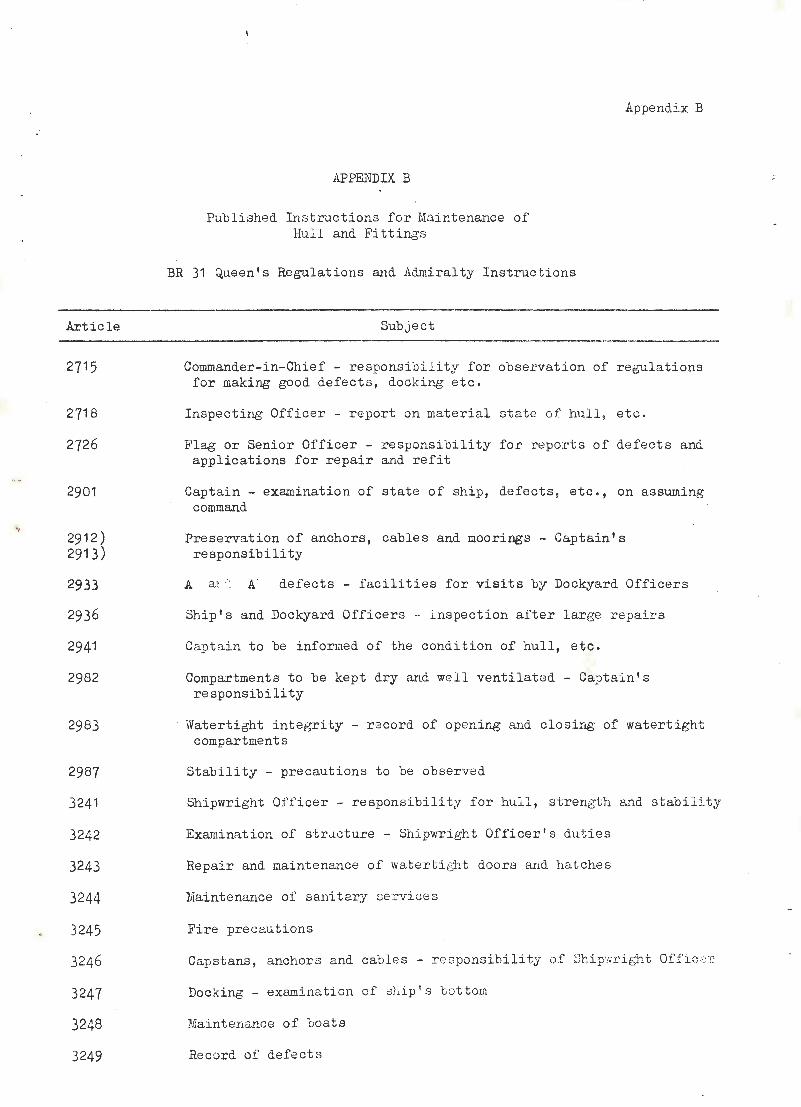
Article
2715
2718
2726
2901
2912) 2913)
2933
2936
2941
2982
2983
2987
3241
3242
3243
3244
3245
3246
3247
3248
3249
APPENDIX B
Published Instn1ctions for Maintenance of Hull and Fitting·s
BR 31 Queen's Regulations and Admiralty Instructions
Subject
Appendix B
Commander-in-Chief - responsibility for obser vation of regulations for making good defects, docking etc .
Inspecting Officer - r eport on material s tate of hull , etc .
Flag or Senior Officer - responsibility for r eports of defects and applications for repair and refit
Captain- examination of stat e of ship, defects , etc . , on assuming command
Preservation of anchors , cab le s and moorings- Captain ' s responsibility
A a·:.... A defects - facilities fo r visits by Dockyard Officers
Ship's and Dockyard Officers - i nspection after large repai r s
Cap tain to be informed of the condition of hull, etc .
Compartments to be kept dry rutd well ventilated - Captai n's responsibility
Watertight integrity - record of opening and closing of watertight compartments
Stability - precautions to be observed
Shipwright Of ficer - responsibility for hull , strength and st abili t y
Examination of str,tc ture - Shipwright Officer 1 s duties
Repair and maintenance of watertight doors e..nd hat che s
Maintenance of sanitary services
Fire precautions
Capstans , anchors and cabl es - ::-esponsi.bi li ty of ~3hip·Nright Offi c:21'
Docking- exe..mina tion of ship ' s bottom
Maintenance of boats
Record of defects

Article
3253
3262
3263
3265
3266
3268
5401
5402
5404
5405
5406
5410
5531
5532 •
5533
5534
5602
5603
5604
5605
5606
v 5607
5608
5609
5610
5641
Appendix B
Subject
Responsibility in the absence of the Shipwright Officer
Rigging, hawsers, etc. - responsibility of Boatswain
Anchors and cables - responsibility of the Boatswain
Security of weather-deck gear
Canvas gear - maintenance by Boatswain
Examination and testing of gear in the Boatswain's charge
Surveys and examinations
Periodical surveys of hull, etc.
Steel ships - examination, maintenance and preservation of structure
Galvanic action - precautions
Survey of escape manholes
Cleaning and painting- responsibility of Dockyard and Ship's Staff
Anchors - working of flukes
Chain cables - periodic survey, Form S 194
Hawsers and associated eQuipment, boats ' slings; examinations and tests
Steel wire ropes - examinations and tests
Dockyard repairs for ships in commission - Form S 339(a)
Record of defects
Defects in ships refitted at another port
Dockyard assistance - periods at which defect lists are to be rendered
Defect lists - Form S 340/D 275 (pink) and Form S 340(b)/D 275(b)
Supplementary defect list
Defects to be made good by Ship's Staff
Defects - naval stores for making good
Repairs at foreign yards - procedure
Perio:iical docking - standar.·d. intervals

Appendix B
Article
5671 to . 5683
5721
Article
2801
2801
2803
2803 to 2808
2812
2810
2811
2831
2832
Subject
Docking at a foreign port
Docking in a private yard
Alterations and additions - procedure and action
Reduction to Reserve - preservation of hull structure
BR 3000 Marine Engineering Manual
Subject
Examination of structure by ship's officers -FormS 180 and Book S 338 complete examination of all accessible structure below the weather deck
Quarterly inspection of certain compartments - compartments in which water is liable to accumulate
Importance of careful examination - treatment of structure
Survey of structure (except FFO tanks) by Dockyard Officers -(a) Aircraft carriers and cruisers - 4-5 years (b) Fast mine-layers, destroyers, frigates and small vessels with
outer bottom plating tin or less thick - at every dockyard refit
(c) Submarines -at every dockyard refit
(d) Other vessels - at alternate dockyard refits (e) Stationary and harbour vessels - complete survey within
4 years.
Air pressure tests of watertight compartments -Ships in commission - at interval not exceeding 2-2i years Ships under reconstruction or major alteration - tests are carried out by Dockyard Officers.
Inspection of bulkheads and decks of WTCs -Visual inspection b~r Ship's Officers at commissioning.
Fuel oil compartments in de stroyers and frigates -Water-pressurP. t es t after repairs affecting watertightness Article 19·13 give s other r egulations for FFO tanks.
Periodica l work1ng of sea va lves -To be opened fully and shut again a t intervals not exc eeding three months.
Salvage pumps a.nd 3Y .s tems ( a ircra ft carriers and dP.pot ships) -Annual t e st by Ship ' s Staf f Test by Do c1-:~rard O fi' lC •~ ~s aft er l ar5e repairs .

Appendix B
Article
2833
2834
2836
2838
2454
2455
2456
2816
0675
0676
( ,-. ...-) · ~ · · ,_; c_.
JS 13
Subject
Portable electric pumps -To be tested under service conditions at intervals not exceeding six months
Flooding and spraying systems, periodical tests -Valves to be worked quarterly Evidence of exceptional marine growth necessitates more frequent testing.
Spraying arrangements, maintenance -All piping between spray valve and spray to be disconnected and
cleaned by dockyard -Steel or ungalvanised iron pipes - every 2-2t years Galvanised pipes - every 3-4 years Non-ferrous or alloyed pipes - 4-5 years.
Hangar drenching system (aircraft carriers) To be tested by actual use every 12 months
Ventilation system -Interior of trunking to be examined quarterly
Warm air supply to living spaces -Adjustment to steam valves and inspection of relief valves Daily examination of fans Periodical greasing of fan bearings.
Air conditioning -Correct running of fan Inspection of trunking.
Watertight doors, hatches and valves -To be examined and worked regularly, preferably once a week In large ships divided into four groups, one being examined and worked weekly, in rotation.
Maintenance of wire rope -Regular lubrication To be examined at least once a month.
Periodical examination and test of lifting appliances -see Appendix c.
'A 1 bracket bushes -Near-down by poker-gauge to be taken by diver when period between dockings exceeds six months.
Re port of examination of propellers - F'orm D 488.

Article
1224
1253
2603
2505 l 2552 2553
2550
Subject
Prevention of external corrosion -
Appendix B
·]
Frequent examination of boiler uptakes, rainwater catchments and their drains.
Funnel uptakes -Examination and adjustment of funnel guys once a week in harbour
Electro-hydraulic steering gear, capstan and hoisting machinery -Examination of one pump unit of eaoh service at intervals not
exceeding two years.
Capstans -Examination by dockyard at each refit
Ropes -Aircraft catapults and arresting gear
Aircraft lifts (aircraft carrier) -Quarterly examination by ship's staff Annual examination by dockyard.

f:
ABR
BR 15
ABR 4
ABR 27
ABR 19
BR 67
BR 31
BR 367
., BR 367A
BR 298
BR 569
BR 862
BR 820
BR 1244
BR 1094
BR 1 Z57
BR 1271
BR 1637
BR 1786
BR 1794
BR 1882
BR 1940
BR 1977( 1)
BR 2170
BH 2171
APPENDIX C
Publications referring to Repair and Maintenance of Hull and Fittings
Catalogue of Books of Reference Etc.
Notes on Leadership Morale and Discipline Etc.
Naval Storekeeping Manual
RAN Training Manual
RAN Painting Manual
Seamanship Manuals, Volumeo 1, 2 and 3
QR and AI
Appendix C
Instructions on Working, Handling, Survey and Repair of Anchors, Chain Cable and Associated Gear
Anchors and Cables and Associated Equipment
Stability of Ships
Practicable Construction of War Ships (Newton)
Naval Magazine and Explosives Regulations (HM Ships)
Provision of Safe Water for Drinking, Cooking, Washing and Similar Purposes
Fouling of Ship's Bottoms by Marine Growth
Warship Ventilation Hand Book
Ships Fire-Fighting Manual
The Laundry Manual
Anchors for Her Majesty's Service
Instructions for the Preservation of Gunnery Equipment
Craft Technical Memoranda I
Habitability Manual for Her Majesty 1 s Ships
Paint procedures for Alurnini.um Alloys
Handbook for the Operab . .:m and Maintenance of 20-man Inflatable Liferafts; Patts. 5b00 and 5603
NBCD Manual - V0lur;~e
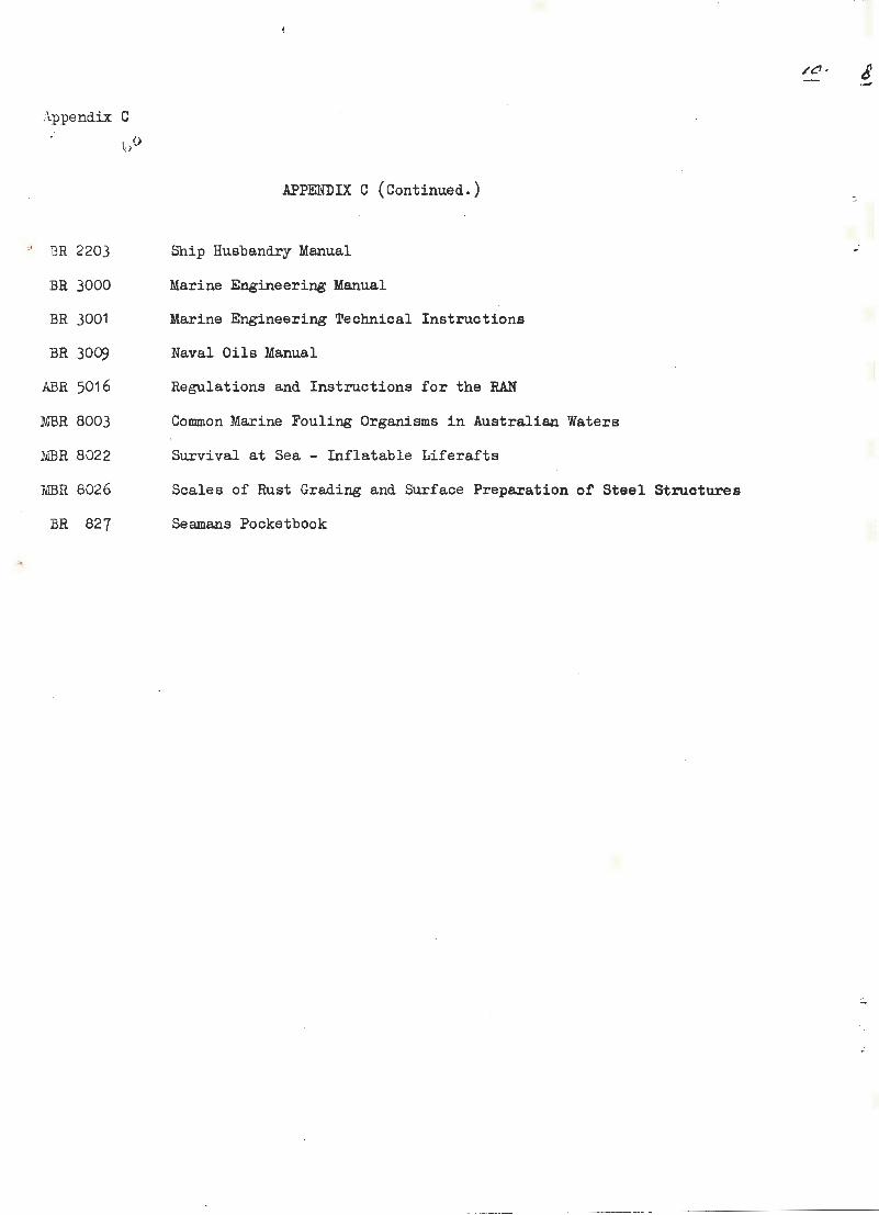
"
Appendix C
~,p
BR 2203
BR 3000
BR 3001
BR 3009
ABR 5016
MBR 8003
MBR 8022
MBR 8026
BR 827
APPElf.DIX C (Continued.)
Ship Husbandry Manual
Marine Engineering Manual
Marine Engineering Technical Instructions
Naval Oils Manual
Regulations and Instructions for the RAN
Common Marine Fouling Organisms in Australian Waters
Survival at Sea - Inflatable Liferafts
Scales of Rust Grading and Surface Preparation of Steel Structures
Seamans Pocketbook
:.
, '
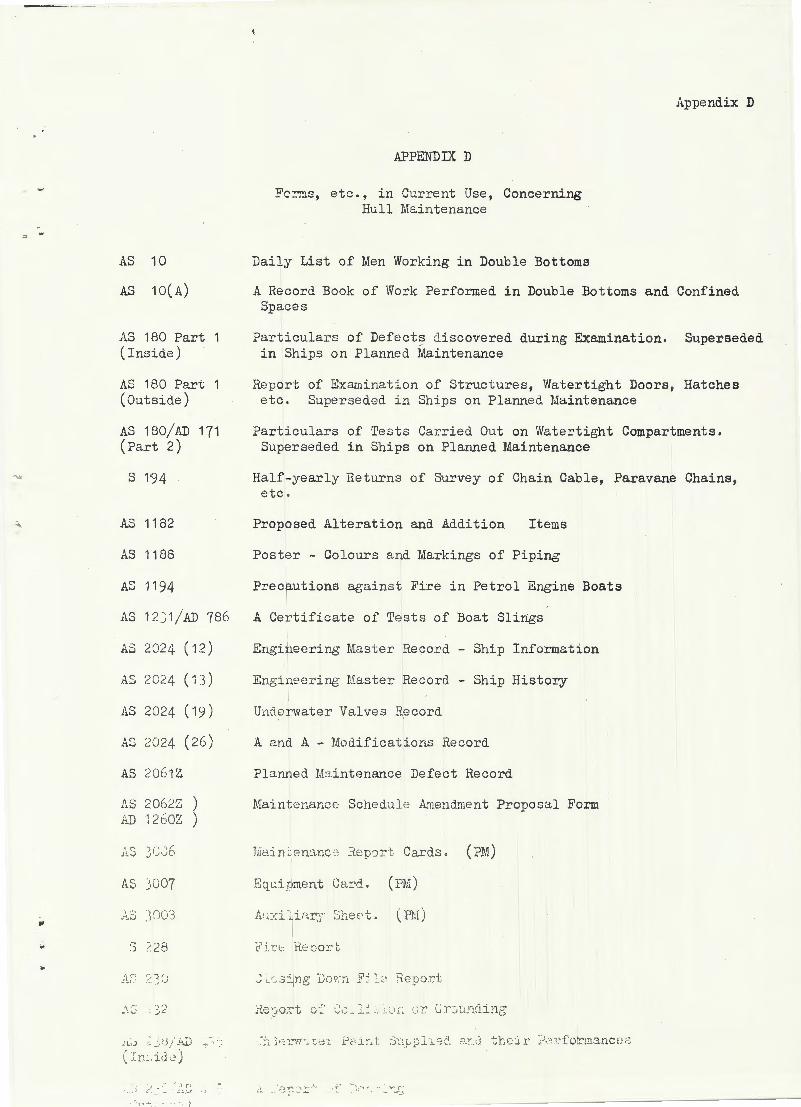
AS 10
AS 10(A)
AS 180 Part (Inside)
AS 180 Part (Outside)
AS 180/AD 171 (Part 2)
s 194
AS 1182
AS 1188
AS 1194
AS 1231/AD 786
AS 2024 (12)
AS 2024 ( 1 3)
AS 2024 ( 19)
""' 2024 (26 ) tj.o..)
AS 20G1Z
.l\.S 2062Z ) AD 1260Z \
)
A:) 1(• ·, 1"' _l ·.JIJO
AS j007
.:~3 Y 'K/-l .. ... :) /. 2[-l
.. ·· ·:-· 2 ~.() ..:~ t
,.,.-; j2 .. ~ ... ..:
H .. ;.) - >j / ; (L',
( J. ! :~. i d :: )
-· . ·- ·lr ' .::. ;..t
·• - ' 1
APPENniX D
Fc~s, etc., in Current Use, Concerning Hull Maintenance
Daily List of Men Working in Double Bottoms
Appendix D
A Record Book of Work Performed in Double Bottoms and Confined Spaces
Particulars of Defects discovered during Examination. Superseded in Ships on Planned Maintenance
Report of Exrunination of Structures, Watertight Doors, Hatches etc. Superseded in Ships on Planned Maintenance
Particulars of Tests Carried Out on Watertight Compartments. Superseded in Ships on Planned Maintenance
Half-yearly Returns of Survey of Chain Cable, Paravane Chains, etc .
Proposed Alteration and Addition Items
Poster - Colours and Markings of Piping
Precautions against Fire in Petrol Engine Boats
A Certificate of Tests of Boat Slings
Engineering Master Record - Ship Information
Engim' E)l~ing Haster Record - Ship History
Unde rwater Valve s Record
A and A - Modifications Record
Planned M:'l.intenance Defect Record
.Maintenance Schedule Amendment Proposal Form
t ':i . .c· i.:: f~E: oor t
, .,., ,_ .... __ .f,
------~-----------

Appendix D
s 326
s 326 (A)
AS 338
AS 338 (A)
AS 541
AS 555
AS 564 (A)
AS 564 (B)
AS 564 (c)
AS 564 (D) ~
AS 564 (E)
AS 565
AS 1120
AS 1562 I s 1575
s 1580
AS 2071Z
AS 425(14)
AS 2110Z (Inside) ~
AS 2110Z (Outside) /
AS 197/AJJ 526
AS 331
AS 3 )1 ..J•
AS ''•i ~; ) '
.: ~., 32~ Z .nu
AS 473/ A0 787
APPENJHX D (Continued.)
Watert ight Integrity Log
Watertight Integrit;y Statement
A Record of Examination of Hull Structure up to Weather Decks and Fittings Affecting Watertight Sub-division Etc.
Covering Instructions for AS 338
A Report of Loss or Breakac;-e of Anchors or Chain Cable
A Poster - How to Operate Nava l Inflatable Liferafts
Poster - Precautions against :F' ire - c;eneral
Poster - Precautions against Fire - Galleys
Poster Precautions against Fire Machinery Space s
Poster - Precautions against Fire - Flammable Materials
Poster - Precautions against Fire - Special Ri sks
Poster - Instr~ctions in the Use of Safety Lamps
Report of Environmental Conditions in HMA Ships
Poster - Regulations for Watertight Openings
Poster - Regulations for NBCD Openings
Poster - 1950 Markings
Report on Application and Performance of Paints
Report of Inspection of H:MA Ships - Hull Structure
Report of Survey and Repair of Support Craft I
Report of Survey and Repair of Support Craft
Amendments to List of Equipment, Portable Fittings, Spare Gear, Drawings a:hd Instruction Books
Large Return and Survey Vouqher
Med. ReturH "'-illl .. iu:::·v-e;y '! oucner
Cover f or List of Portab~e ?itt i ~cs
------------ - ----

-.....,____ _, __
Appendix D
APPENDIX D (Co nt inued . )
-· AS 473C/ AD 787C
Certificate "A" (First Char ge ) ·=• ... ._
AS 473D/ AD 787D
Certificate "B" (Transfer)
AS 473E/ AD 787E
Certificate "C 11 (Closure)
AS 2022/ AD 400 Report of Defective Materials and Design
AS List of Printed Forms - I-IMA Ships and Commissioned Establishlner.ts
..