Rover Technology: Enabling Scalable Location-Aware …moustafa/papers/cs_tr_4312.pdf · Rover...
14
Rover Technology: Enabling Scalable Location-Aware Computing Suman Banerjee, Sulabh Agarwal, Kevin Kamel, Andrzej Kochut, Christopher Kommareddy, Tamer Nadeem, Pankaj Thakkar, Bao Trinh, Adel Youssef, Moustafa Youssef, Ron Larsen, A. Udaya Shankar, Ashok Agrawala MIND Lab, UMIACS and Department of Computer Science University of Maryland, College Park, MD 20742, USA UMIACS-TR 2001-89 and CS-TR 4312 December 2001 Abstract Location-aware computing involves the automatic tailoring of information and services based on the cur- rent location of the user. We have designed and implemented Rover, a system that enables location-based services, as well as the traditional time-aware, user-aware and device-aware services. To achieve system scalability to very large client sets, Rover servers are implemented in an “action-based” concurrent soft- ware architecture that enables fine-grained application-specific scheduling of tasks. We have demonstrated feasability through implementations for both outdoor and indoor environments on multiple platforms. 1 Introduction A user is shopping in a mall. On entering a store, he pulls out a PDA and browses through detailed information about the products on display. Satisfied with the information, through the PDA, he makes an online purchase of the items of interest, that will be subsequently shipped to his home directly. As he walks on to the next store, which happens to be a video rental store, information on newly-released movies in his favorite categories are downloaded automatically into his PDA, along with their availability information. He chooses a couple of these movies and indicates that he will pick them up at the storefront. His membership discounts are applied to the bill, and he confirms the charge to his credit card. The intriguing aspect of this scenario is the automatic tailoring of information and services based on the current location of the user. We refer to this paradigm as location-aware computing. The different technology components needed to realize location-aware computing are present today, powered by the increasing capa- bilities of mobile personal computing devices and the increasing deployment of wireless connectivity (IEEE 802.11 wireless LANs [7], Bluetooth [1], Infra-red [2], Cellular services, etc.) What has hindered its ubiquitous deployment is the lack of system-wide integration of these components in a manner that scales with large user populations. In this paper, we describe the design and initial implementation experience of such a system, which we call Rover, and discuss the impact such a system can have on the next generation of applications, devices, and users. Rover enables services with the following characteristics: Location-aware, in addition to the more traditional notions of time-aware, user-aware, and device-aware. Rover has a location service that can track the location of every user, either by automated location de- termination technology (for example, using signal strength or time difference) or by the user manually entering current location (for example, by clicking on a map). 1
Transcript of Rover Technology: Enabling Scalable Location-Aware …moustafa/papers/cs_tr_4312.pdf · Rover...

Rover Technology: Enabling Scalable Location-Aware Computing
Suman Banerjee, Sulabh Agarwal, Kevin Kamel, Andrzej Kochut, Christopher Kommareddy,Tamer Nadeem, Pankaj Thakkar, Bao Trinh, Adel Youssef, Moustafa Youssef,
Ron Larsen, A. Udaya Shankar, Ashok Agrawala
MIND Lab, UMIACS and Department of Computer ScienceUniversity of Maryland, College Park, MD 20742, USA
UMIACS-TR 2001-89 and CS-TR 4312December 2001
Abstract
Location-aware computing involves the automatic tailoring of information and services based on the cur-rent location of the user. We have designed and implemented Rover, a system that enables location-basedservices, as well as the traditional time-aware, user-aware and device-aware services. To achieve systemscalability to very large client sets, Rover servers are implemented in an “action-based” concurrent soft-ware architecture that enables fine-grained application-specific scheduling of tasks. We have demonstratedfeasability through implementations for both outdoor and indoor environments on multiple platforms.
1 Introduction
A user is shopping in a mall. On entering a store, he pulls out a PDA and browses through detailed informationabout the products on display. Satisfied with the information, through the PDA, he makes an online purchaseof the items of interest, that will be subsequently shipped to his home directly. As he walks on to the next store,which happens to be a video rental store, information on newly-released movies in his favorite categories aredownloaded automatically into his PDA, along with their availability information. He chooses a couple of thesemovies and indicates that he will pick them up at the storefront. His membership discounts are applied to thebill, and he confirms the charge to his credit card.
The intriguing aspect of this scenario is the automatic tailoring of information and services based on thecurrent location of the user. We refer to this paradigm as location-aware computing. The different technologycomponents needed to realize location-aware computing are present today, powered by the increasing capa-bilities of mobile personal computing devices and the increasing deployment of wireless connectivity (IEEE802.11 wireless LANs [7], Bluetooth [1], Infra-red [2], Cellular services, etc.)
What has hindered its ubiquitous deployment is the lack of system-wide integration of these components ina manner that scales with large user populations. In this paper, we describe the design and initial implementationexperience of such a system, which we call Rover, and discuss the impact such a system can have on the nextgeneration of applications, devices, and users.
Rover enables services with the following characteristics:
� Location-aware, in addition to the more traditional notions of time-aware, user-aware, and device-aware.Rover has a location service that can track the location of every user, either by automated location de-termination technology (for example, using signal strength or time difference) or by the user manuallyentering current location (for example, by clicking on a map).
1

� Available via a variety of wireless access technologies (IEEE 802.11 wireless LANs, Bluetooth, Infra-red, cellular services, etc.) and devices (laptop, PDA, cellular phone, etc.), and allows roaming betweenthe different wireless and device types. Rover dynamically chooses between different wireless links andtailors application-level information based on the device and link layer technology.
� Scales to a very large client population, for example, thousands of users. Rover achieves this throughfine-resolution application-specific scheduling of resources at the servers and the network.
We will use a museum tour application as an example to illustrate different aspects of Rover. We considera group of users touring the museums in Washington D.C. At a Rover registration point in a museum, each useris issued a handheld device with audio and video capabilities, say an off-the-shelf PDA available in the markettoday. Alternatively, if a user possesses a personal device, he can register this device and thus gain access toRover. The devices are trackable by the Rover system. So as a user moves through the museum, information onrelevant artifacts on display are made available to the user’s device in various convenient forms, for example,audio or video clips streamed to the device. Users can query the devices for building maps and optimal routesto objects of their interest. They can also reserve and purchase tickets for exhibitions and shows in the museumlater in the day. The group leader can coordinate group activities by sending relevant group messages to theusers. Once deployed, the system can be easily expanded to include many other different services to the users.
The next section gives a description of the kinds of services that are available through Rover. The successivesections provide an overview of the Rover architecture and a description of a concurrent software architecturethat has been used for system scalability. The following sections expand on particular aspects of Rover, includ-ing clients, servers, data management and multi-Rover systems. Then we describe our initial implementationexperience and conclude with ongoing and future work.
2 Rover Services
The services provided by Rover to its users can be classified as follows:
� Basic data services: Rover enables a basic set of data services in different media formats, including text,graphics, audio, and video. Users can subscribe to specific data components dynamically through thedevice user interface. Depending on the capabilities of the user’s device, only a select subset of mediaformats may be available to the user. This data service primarily involves one-way interaction; dependingon user subscriptions, appropriate data is served by the Rover system to the client devices.
� Transactional services: These services have commit semantics that require coordination of state betweenthe clients and the Rover servers. A typical example is e-commerce interactions.
Services that require location manipulation are a particularly important class of data services in Rover. Lo-cation is an important attribute of all objects in Rover. The technique used to estimate the location of an object(some techniques are described in the Appendix) significantly affects the granularity and accuracy of the loca-tion information. Therefore an object’s location is identified by a tuple of Value, Error, and Timestamp. Theerror identifies the uncertainty in the measurement (value). The timestamp identifies when the measurementwas completed. The accuracy of the location information is relevant to the context of its use. For example,an accuracy of
�meters is adequate to provide walking directions from the user’s current location to another
location about 500 meters away. However, this same accuracy is inadequate to identify the exhibit in front ofthe user. User input in these cases, helps significantly improve the accuracy of user location information.
Map-based services are an important component of location manipulation services. Rover maps can besubject to various operations before being displayed to users:
2

Rover Controller
Database
Streaming
Media Unit
Location ServerClient Devices
Base Stations
Internet/PSTN
Local
Network
Firewall
Rover system Rover system
Rover systemInter Controller protocols
Figure 1: Physical architecture of the Rover System
� Filter: Objects in a Rover map have a set of attributes that identify certain properties of the objects. De-pending on the user’s context (which indicates the user’s interests), filters are generated for the attributevalues of interest to the user. These filters are applied to maps to select the appropriate subset of objectsto display to the user. For example, one user may be interested in only the restaurants in a specific area,while another user needs to view only the museum and exhibition locations. The filters can be dynami-cally changed to appropriately change the objects being displayed on the map.
� Zoom: The zoom level of a displayed map identifies its granularity. The zoom level at a client device ischosen based on the user’s context. For example, a user inside a museum gets a detailed museum map,but when the user steps outside the museum, he gets an area map of all the museums and other pointsof interest in the geographic vicinity. The zoom level can be implemented as an attribute of objects, andappropriate filters can then be applied to display a map at the desired zoom level.
� Translate: This functionality enables the map service to automatically update the view of the displayedmap on the client device as the user moves through the system. When the location of the user movesout of the central region of the currently displayed map, the system prepares a new map display, that isappropriately translated from the previously displayed map.
3 Rover Architecture
A Rover system, depicted in Figure 1, consists of the following entities:
� End-users of the system. Rover maintains a user profile for each end-user, that defines specific interestsof the user and is used to customize the content served.
� Rover-clients are the client devices through which users interact with Rover. They are typically smallwireless handheld units with great diversity of capabilities in regard to processing, memory and storage,graphics and display, and network interface. Rover maintains a device profile for each device, identifyingits capabilities and thus, the functionality available at that device.
3
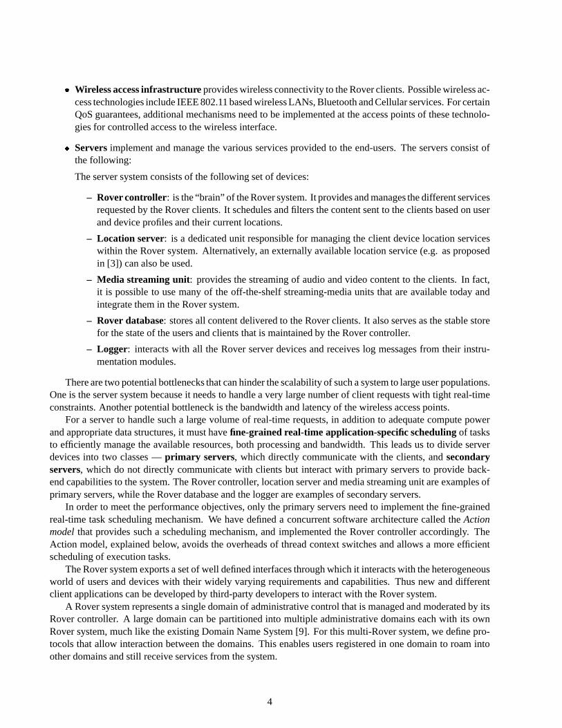
� Wireless access infrastructure provides wireless connectivity to the Rover clients. Possible wireless ac-cess technologies include IEEE 802.11 based wireless LANs, Bluetooth and Cellular services. For certainQoS guarantees, additional mechanisms need to be implemented at the access points of these technolo-gies for controlled access to the wireless interface.
� Servers implement and manage the various services provided to the end-users. The servers consist ofthe following:
The server system consists of the following set of devices:
– Rover controller: is the “brain” of the Rover system. It provides and manages the different servicesrequested by the Rover clients. It schedules and filters the content sent to the clients based on userand device profiles and their current locations.
– Location server: is a dedicated unit responsible for managing the client device location serviceswithin the Rover system. Alternatively, an externally available location service (e.g. as proposedin [3]) can also be used.
– Media streaming unit: provides the streaming of audio and video content to the clients. In fact,it is possible to use many of the off-the-shelf streaming-media units that are available today andintegrate them in the Rover system.
– Rover database: stores all content delivered to the Rover clients. It also serves as the stable storefor the state of the users and clients that is maintained by the Rover controller.
– Logger: interacts with all the Rover server devices and receives log messages from their instru-mentation modules.
There are two potential bottlenecks that can hinder the scalability of such a system to large user populations.One is the server system because it needs to handle a very large number of client requests with tight real-timeconstraints. Another potential bottleneck is the bandwidth and latency of the wireless access points.
For a server to handle such a large volume of real-time requests, in addition to adequate compute powerand appropriate data structures, it must have fine-grained real-time application-specific scheduling of tasksto efficiently manage the available resources, both processing and bandwidth. This leads us to divide serverdevices into two classes — primary servers, which directly communicate with the clients, and secondaryservers, which do not directly communicate with clients but interact with primary servers to provide back-end capabilities to the system. The Rover controller, location server and media streaming unit are examples ofprimary servers, while the Rover database and the logger are examples of secondary servers.
In order to meet the performance objectives, only the primary servers need to implement the fine-grainedreal-time task scheduling mechanism. We have defined a concurrent software architecture called the Actionmodel that provides such a scheduling mechanism, and implemented the Rover controller accordingly. TheAction model, explained below, avoids the overheads of thread context switches and allows a more efficientscheduling of execution tasks.
The Rover system exports a set of well defined interfaces through which it interacts with the heterogeneousworld of users and devices with their widely varying requirements and capabilities. Thus new and differentclient applications can be developed by third-party developers to interact with the Rover system.
A Rover system represents a single domain of administrative control that is managed and moderated by itsRover controller. A large domain can be partitioned into multiple administrative domains each with its ownRover system, much like the existing Domain Name System [9]. For this multi-Rover system, we define pro-tocols that allow interaction between the domains. This enables users registered in one domain to roam intoother domains and still receive services from the system.
4

4 Action model
In order to achieve fine-grained real-time application-specific scheduling, the Rover controller is built accordingto a concurrent software architecture we call the action model. In this model, scheduling is done in “atomic”units called actions. An action is a “small” piece of code that does not have any intervening I/O operations.Once an action begins execution, it cannot be pre-empted by another action. Consequently, given a specificserver platform, it is easy to accurately bound the execution time of an action. The actions are executed in acontrolled manner by an Action Controller.
We use the term server operation to refer to a transaction, either client- or administrator-initiated, thatinteracts with the Rover controller; examples in the museum scenario would be registerDevice, getRoute andlocateUser. A server operation consists of a sequence (or more precisely, a partial order) of actions interleavedby asynchronous I/O events. Each server operation has exactly one “response handling” action for handling allI/O event responses for the operation; i.e., the action is eligible to execute whenever an I/O response is received.
A server operation at any given time has zero or more actions eligible to be executed. A server operationis in one of the following three states:
� Ready-to-run: At least one action of the server operation is eligible to be executed but no action of theserver operation is executing.
� Running: One action of the server operation is executing (in a multi-processor setup, several actions ofthe operation can be executing simultaneously).
� Blocked: The server operation is waiting for some asynchronous I/O response and no actions are eligibleto be executed.
The Action Controller uses administrator-defined policies to decide the order of execution of the set of eligibleactions. The scheduling policy can be a simple static one, such as priorities assigned to server operations, butit can equally well be time based, such as earliest-deadline-first or involving real-time cost functions. In anycase, the controller picks an eligible action and executes it to completion, and then repeats, waiting only if thereare no eligible actions (presumably all server operations are waiting for I/O completions).
The management and execution of actions are done through a simple Action API defined as follows:
� init (action id, function ptr): This routine is called to initialize a new action (identified by action id) fora server operation. Function ptr identifies the function (or piece of code) to be executed when the actionruns.
� run (action id, function parameters, deadline, deadline failed handler ptr): This routine is called to markthe action as eligible to run. Function parameters are the parameters used in executing this instance ofthe action. Deadline is optional and indicates the time (relative to the current time) by which the actionshould be executed. This is a soft deadline, that is, its violation leads to some penalty but not system fail-ure. If the action controller is unable to execute the action within the deadline, it will execute the functionindicated by deadline failed handler ptr. This parameter can be NULL, indicating that no compensatorysteps are needed.
� cancel (action id, cancel handler ptr): This routine is called to cancel a ready-to-run action provided itis not executing. Cancel handler ptr indicates a cleanup function. It can be NULL.
Actions vs Threads: Our need to scale to very large client populations made us adopt the action model ratherthan the more traditional thread model. We now provide some experimental justification.
5

There are several ways to use a thread model to implement the Rover controller. One is to implement eachserver operation as a separate thread. Another is to have a separate thread for each user. Both of these imply alarge number of simultaneously active threads as we scale to large user populations, resulting in large overheadsfor thread switching. A more sensible approach is to create a small set of “operator” threads that execute alloperations, for example, one thread for all registerDevice operations, one for all locateUser operations, and soon. Here the thread switching overhead is modest but there are drawbacks. One is that, depending on the threadspackage, it restricts our ability to optimize thread scheduling, especially as we transit to time-based (rather thanpriority based) scheduling. More importantly, because each operator thread executes its set of operations insequence, this approach severely limits our ability to optimally schedule the eligible actions within an operationand across operations. Of course, each thread could keep track of all its eligible actions and do scheduling atthe action level, but this is essentially recreating the action model within each thread.
ServerOperation A {
Compute Block A . . . .
File I/O
Compute Block A . . . .
File I/O
Compute Block A . . . .
}
write(...);
Log to diskwrite(...);
Figure 2: Scenario A has 10,000 processor-boundserver operations where computation is inter-leaved with file write operations
ServerOperation B {
Compute Block B Net I/O
Compute Block B
Net I/O
Compute Block B }
sendto(...);recvfrom(...);
sendto(...);recvfrom(...);
Database
Figure 3: Scenario B has 100 I/O bound serveroperations where computation is interleaved withnetwork I/O interactions
We compare the performance of action-based and thread-based systems through implementation. In thispaper, we consider two kinds of server operations, one processor-bound and the other, I/O-bound, both of whichappear in the context of the Rover controller. Using these server operations, we construct two correspondingscenarios:
1. Scenario A: This is a computation-intensive scenario and has 10,000 processor-bound server operations,where each of the server operations has three compute blocks, interleaved with two file write operations(see Figure 2). In each of these server operations, the second and the third I/O compute block do not needto await for the prior file I/O write operation to complete.
2. Scenario B: This is an I/O-intensive scenario and has 100 I/O-bound server operations, where each of theserver operations has three compute blocks, interleaved with two network I/O operations (see Figure 3).In each of these server operations, the second and third compute blocks can be initiated only after thecompletion of the prior network I/O operation. The network I/O interaction was implemented using UDP.Since our focus is on the comparison of the action-based versus the thread-based systems, we avoidedissues of packet loss and re-transmissions by only considering those experiments where no UDP packetswere lost in the network.
6

We consider two execution platforms, referred to as M1 and M2 in the paper. M1 comprises of a Intel PentiumIII (600 MHz) processor and 96 MB of RAM which runs Linux. M2 comprises of a Sun Ultra 5, with a Sparc(333 MHz) processor and 128 MB RAM and runs Solaris. For the thread-based implementation, we used theLinuxThreads library for the M1 platform and the Pthreads library for the M2 platform, both of which are im-plementations of the Posix 1003.1c threads package. This total execution time for the three compute blocksin each server operation A was 0.1518 ms for M1 and 0.9069 ms for M2. The ping network latency for thenetwork I/O in server operation B varied between 30-35 ms.
We compared performances of an action-based implementation and a thread-based implementation of thetwo scenarios for the different platforms. In the action-based implementation each compute block is imple-mented as a separate action. In the thread-based implementation, we experimented with a different number ofthreads, where each thread executed an equal number of server operations for perfect load balancing betweenthe different threads.
Action-based Thread-based (threads used)Scenario Machine Specifications 1 5 10 50 100A (Fig. 2) M1: Pentium/Linux 24.27 299.36 299.93 300.46 304.50 310.31A (Fig. 2) M2: Sparc/Solaris 62.82 1000.9 1012.54 1041.60 1012.83 1031.25B (Fig. 3) M1 Controller, M2 Database 11.61 3711.94 1302.20 1011.49 893.10 728.30
Table 1: Comparisons of overheads for action-based and thread-based systems (in ms)
In Table 1, we present the overheads obtained in each case, where the overhead is the total execution timeminus the fixed, identical and unavoidable computation/communication costs for the two scenarios. We reportthe mean execution overheads of a large number of runs, which were required to obtain low variance. For thecomputation-intensive server operations there are very little performance gains in trying to overlap computa-tion with communication (file I/O), and is not substantial enough to justify the overheads of a multi-threadedimplementation. Therefore, a thread-based system with a single thread achieves the best performance amongthe thread-based implementations.
For the I/O intensive server operations, using a multi-threaded implementation is useful, since computa-tion and communication can be overlapped. Consequently, the best performance for the thread-based systemis achieved, when the maximum number of threads are used (one thread for each server operation).
As can be observed in both scenarios, the action-based implementation still achieves significantly (aboutan order of magnitude) less overheads as compared to the best thread-based implementation.
5 Rover Clients
The client devices in Rover are handheld units of varying form factors, ranging from powerful laptops to sim-ple cellular phones. They are categorized by the Rover controller based on attributes identified in the deviceprofiles, such as display properties — screen size and color capabilities, text and graphics capabilities, process-ing capabilities — ability to handle vector representations and image compression, audio and video deliverycapabilities and user interfaces. The Rover controller uses these attributes to provide responses to clients in themost compatible formats.
For the wireless interface of client devices, we have currently considered two link layer technologies —IEEE 802.11 Wireless LAN and Bluetooth. Bluetooth is power efficient and is therefore better at conservingclient battery power. According to current standards, it can provide bandwidths of upto 2 Mbps. In contrast,IEEE 802.11 wireless is less power-efficient but is widely deployed and can currently provide bandwidths ofupto 11 Mbps.
7

In areas where these high bandwidth alternatives are not available, Rover client devices will use the lowerbandwidth air interfaces provided by cellular wireless technologies that use CDMA [11] or TDMA based tech-niques. In particular, cellular phones can connect as clients to Rover, which implies that the Rover systeminterfaces with cellular service providers.
Different air-interfaces may be present in a single Rover system or in different domains of a multi-Roversystem. In either case, software radios [8] is an obvious choice to integrate different air-interface technologies.
While the location management system is not tied to a particular air interface, certain properties of specificair interfaces can be leveraged to better provide location management (discussed in the Appendix).
Transport
LocationService
Admin Interface Back-end Interface
Location Interface
Content Mgmt.
Instrumentation
Logger
User Infobase
Content Infobase
AdministratorBilling/E-commerce
Services
Content Provider
ServerAssistants’Interface
Content Interface
Actions
User/Device Profile Mgmt.
ActionScheduler
andController
Security Policies
Rover Server
Client Devices
Figure 4: Logical architecture of a Rover system
6 Rover Controller
The interaction of the Rover controller with all other components of the system is presented in Figure 4. TheRover controller interacts with the external world through the following interfaces:
� Location Interface: This interface is used by the Rover controller to query the location service about thepositions of client devices. The location of a device is defined as a tuple representing the estimate of itsposition (either absolute or relative to some well-known locations), the accuracy of the estimate, and thetime of location measurement. Depending on the technology being used to gain position estimates, Theaccuracy of the estimate depends on the particulars of the location technology, for example, GPS [6],IEEE 802.11 signal strength, signal propagation delays, etc. Rover takes into account this accuracy in-formation when making location-based decisions.
� Admin Interface: This interface is used by system administrators to oversee the Rover system, includ-ing monitoring the Rover controller, querying client devices, updating security policies, issuing systemspecific commands, and so on.
8

� Content Interface: This interface is used by the content provider to update the content that is served bythe Rover controller to the client devices. Having a separate content interface decouples the data fromthe control path.
� Back-end Interface: This interface is used for interaction between the Rover controller and certain exter-nal services as may be required. One such service is e-commerce, by which credit card authorization forvarious purchases can be made. These services would typically be provided by third-party vendors.
� Server Assistants Interface: This interface is used for interaction of the Rover controller with the sec-ondary servers. e.g. the database and the streaming media unit.
� Transport Interface: This is the communication interface between the Rover controller and the clients,which identify data formats and interaction protocols between them.
7 Rover Database
The database in Rover consists of two components, which together decouple client-level information from thecontent that is served.
One component of the database is the user infobase, which maintains user and device information of allactive users and devices in the system. It contains all client-specific contexts of the users and devices, namelyprofiles and preferences, client location, and triggers set by the clients. This information changes at a fairlyregular rate due to client activities, e.g. the client location alters with movements. The Rover controller hasthe most updated copy of this information and periodically commits this information to the database. For manyof these data items (e.g. client location), the Rover controller lazily updates the database. These are termedas volatile data since any change to these data items are not guaranteed to be accurately reflected by the sys-tem across system crashes. For some others, (e.g. new client registration) the Rover controller commits thisinformation to the database before completing the operation. These are termed as non-volatile data. The Rovercontroller, identifies some parts of the data to be volatile, so as to avoid very frequent database transactions.The Rover controller does not guarantee perfect accuracy of the volatile data, and thus trades off accuracy withefficiency for these data components.
The other component in the database is the content infobase. This stores the content that is served by theRover controller and changes less frequently. The content provider of the Rover system is responsible for keep-ing this infobase updated. In the museum example, this component stores all text and graphical informationabout the various artifacts on display.
The Rover database implements an extended-SQL interface that is accessed by the Rover controller. Apartfrom the usual SQL functionality, it also provides an API for retrieval of spatial information of different objectsand clients in the system.
The transactions of the Rover controller with the database are executed on behalf of the different serveroperations. The transactions, by definition, are executed atomically by the database. Additionally, each trans-action is identified by two different flags that identify certain properties for execution, as follows:
� Lock-Acquiring: If this flag is set, the transaction is required to acquire relevant locks, on behalf of theserver operation, to read or write data to the database. It also requires that these locks will be released bythe server operation prior to its termination at the Rover controller.
� Blocking: If a transaction issued by a server operation is unable to access or modify some data due tolocks being held by other server operations, it can either block till it successfully reads the data, or itreturns immediately to the server operation without successfully execution. If the Blocking flag is set fora transaction, then the first option is chosen for the transaction.
9

To avoid deadlocks, server operations acquire the relevant locks on data items stored in the database usinga Two Phase Locking protocol with a lexicographic ordering of lock acquiring for data items. It is importantto note that server operations may need to acquire locks at the database, if and only if they need to access thestored data through multiple transactions and all these transactions need to have the same data view. This is notrequired for the vast majority of server operations that either make a single database transaction, or do not needits multiple transactions to have identical views. None of the server operations in the current implementation ofRover, required to acquire locks at the database. The transactions themselves might acquire and release locksat the database during their execution, which are not visible to the server operations at the Rover controller.
8 Multi-Rover System
A single Rover system comprises of a single Rover controller, other server devices (e.g., Rover database andRover streaming media unit), and a set of Rover clients. A single system is sufficient for management of Rover-clients in a zone of single administrative control. For example, consider a Rover system in a single museum. Allartifacts and objects on display in the museum are managed by a single administrative entity. There is a singlecontent provider for this system and a single Rover system is appropriate to serve all visitors to this museum.
However, each separate museum has its independent administrative authority. Therefore, we can have aseparate Rover system for each of the different museums that are administered separately by each museum au-thority. This allows a decentralized administration of the independent Rover systems, locally by each museumauthority. However, it is important to provide a seamless experience to visitors as they roam from museumto museum. A multi-Rover system is a collection of independent Rover systems that peer with each other toprovide this seamless connectivity to the user population.
The design of a multi-Rover system is similar in spirit to the Mobile IP [10] solution to provide networklayer mobility to devices. Each client device has a home Rover system to which it is registered. As the devicephysically moves into the zone of a different, or foreign Rover system, it needs to authenticate itself with theRover controller of the foreign system. Based on administrative policies, the two Rover systems have service-level agreements that define the services that they will provide to clients of each other.
When the Rover controller of a system detects a foreign client device, it first checks whether it has an appro-priate service-level agreement with the Rover controller of the device’s home system. If one exists, the Rovercontroller of the foreign system requests transfer of relevant state about the client device from the Rover con-troller of the home system and subsequently provides necessary services to it. Rover controllers of differentRover system use the Inter-Controller protocols to interact.
9 Initial Implementation
We have successfully built Rover prototype systems and tested them in the campus of University of MarylandCollege Park. The implementation has been demonstrated for both indoor and outdoor environments. A pre-liminary test implementation was developed on Windows based systems (Windows 2000 for the controller andWindows CE for the client devices). The current implementation of the Rover system has been developed underthe Linux operating system. The Rover controller is implemented on a Intel Pentium machine running RedHatLinux 7.1 and the clients are implemented on Compaq iPAQ Pocket PC (model H3650) running the Familiardistribution (release versions 0.4 and 0.5) of Linux for PDAs1. Wireless access is provided using IEEE 802.11wireless LANs. Each Compaq iPAQ is equipped with a wireless card which is attached to the device throughan expansion sleeve.
We have experimented with a set of 8 client devices and have tested various functionalities of the system.
1Available at http://familiar.handhelds.org
10

Figure 5: View of the display of a Rover-client
For our outdoor experiments, we interfaced a GPS-device (Garmin e-Trex) to the Compaq iPAQs and ob-tained device location accuracy of between 3-4 meters. The display of the iPAQ Rover-client displays the lo-cations of the different users (represented by the dots) on the area map as shown in Figure 5.
The indoor Rover system is implemented for the 4th floor of the A.V. Williams Building (where the Com-puter Science Department is located), whose map is shown in Figure 6. In this implementation, the locationservice is being provided using signal strength measurements from different base stations. There are about 12base stations that are distributed all over the building and typically the client device can receive beacons fromfive or six of the base stations. We are able to get an accuracy of better than a meter in this environment, usingvery simple signal-strength based estimation techniques.
In both these cases, we implemented the basic functionality of the Rover system. They include:� User activation/de-activation and device registration/de-registration procedures.
� Periodic broadcast of events of interest from the Rover controller to the users in specific locations.
� Interaction between users. This can be either simple text messaging or voice chat. Users can optionallymake their location visible to other users. In the museum example, a tour group coordinator can use thisfeature to locate all the other members of the group.
� Users can request alerts from the Rover controller when certain conditions are met. The conditions maybe time, location or context dependent. This can be used to provide notification to ticket holders of anapproaching show time. Clearly, for the users who are further away from the show venue, this notificationneeds to be provided early enough, so that they have enough time to reach the venue.
� An administrator’s console allows a global view of all users and their locations in the system. The ad-ministrator can directly interact with all or a specific subset of the users based on the location or otherattributes of the users.
Currently, we are implementing more functionality in the Rover controller.
10 Conclusions and Future Work
Rover is currently available as a deployable system using specific technologies, both indoors and outdoors. Ourfinal goal is to provide a completely integrated system that operates under different technologies, and allows
11

26.6 m
70.0 m
Figure 6: The indoor Rover system is currently implemented in the 4th floor of the A.V. Williams Building atthe University of Maryland.
a seamless experience of location-aware computing to clients as they move through the system. With this inmind, we have a set of different projects in both the short and the long term.
� Experiment with a wider range of client devices, specially the ones with limited capabilities. They includedevices with low-resolution graphics, limited color choices, or only a few lines of text display area.
� For the more-capable devices, we are experimenting with location-aware streaming video services.
� Integrate different other wireless air interfaces to the Rover system. Bluetooth-based LAN is emergingas an important standard today, and it is a logical next technology to experiment with. In the longer term,we are expecting to interact with cellular providers to define and implement mechanisms that will allowRover clients to interact over the cellular interface.
� Implement the other different location services. We are currently building custom hardware that willallow the deployment of the PinPoint Technology (see Appendix) for device location. We are also ex-perimenting with other mechanisms for better location estimation.
� Implement the multi-Rover system.
� Campus-wide deployment of Rover. In the near term, we are hoping to deploy a Rover system in the cam-pus of the University of Maryland, College Park. Initially, independent Rover systems will be deployedto serve clients of specific departments. Beyond that these systems will be able to interact using the inter-Rover Controller protocols of a multi-Rover system. The Rover controllers will be co-located with theweb servers, and the content management will be handled jointly for both the systems in an integratedmanner.
We believe that Rover Technology will greatly enhance the user experience in a large number places, includingvisits to museums, amusement and theme parks, shopping malls, game fields, offices and business centers. Thesystem has been designed specifically to scale to large user populations. Therefore, we expect the benefits ofthis system to be higher in such large user population environments.
12

References
[1] http://www.bluetooth.com.
[2] http://www.irda.org.
[3] J. Agre, D. Akenyemi, L. Ji, R. Masuoka, and P. Thakkar. A Layered Architecture for Location-basedServices in Wireless Ad Hoc Networks. In Proceedings of IEEE Aerospace Conference, March 2002.
[4] P. Bahl and V.N. Padmanabhan. RADAR: An in-building RF-based user location and tracking system. InProceedings of Infocom, Tel Aviv, Israel, March 2000.
[5] N. Davies, K. Cheverst, K. Mitchell, and A. Efrat. Using and Determining Location in a Context-SensitiveTour Guide. IEEE Computer, 34(8), August 2000.
[6] B. Hofmann-Wellenhof, H. Lichtenegger, and J. Collins. GPS: Theory and Practice. Springer-Verlag,Wein, NY, 1997.
[7] IEEE. Wireless LAN medium access control (MAC) and physical layer (PHY) specification, Standard802.11, 1999.
[8] J. Mitola. The Software Radio Architecture. IEEE Communications Magazine, 5, May 1995.
[9] P. Mockapetris. Domain names - implementation and specification, RFC 1035, November 1987.
[10] C.E. Perkins. IP mobility support, RFC 2002, October 1996.
[11] A.J. Viterbi. CDMA: Principles of Spread Spectrum Communications. Addison-Wesley, 1995.
A Location Determination Techniques
The location service in Rover is decoupled from the Rover controller. Both the clients and the Rover controllercan directly interact with an external location service to obtain client locations. We outline some of the differenttechnologies that are available to provide client location information. Some of these techniques are applicableto specific clients operating with specific technologies.
� GPS: Perhaps the most popular option of obtaining location information today is through the use of GPSreceivers. Here the client device interfaces with a GPS receiver; no other infrastructure is required. GPScan provide user location to an accuracy of around 3 meters provided the device has good signal receptionfrom at least four GPS satellites. The main problem with GPS is that it is generally not workable indoors.
� E-911: Another option is the E-911 emergency location service that cellular service providers are re-quired by the FCC to provide between October 2001 and December 2005. According to the requirementsfor this Automatic Location Information (ALI) the cellular system should be able to locate the calling de-vice to within an accuracy of 50 to 300 meters depending on specific systems being used. Here, the clientdevices would be cell phones and the Rover system would interface with the cellular service provider (forboth location and data connectivity).
� WLAN signal strength: Another option, motivated by the increasing popularity of wireless LANs in-doors, is to determine the position of a client device relative to the base station positions based on the
13

received signal strength from base stations at the client device [4]. [One could also use the received sig-nal strength from the client at the different base stations, but this requires access and modification to thebase stations.]
The determination of location information from signal strength is nontrivial because the strength of areceived signal depends not only on the distance between the transmitter and receiver but also on ob-structions and multipath interference. Nonetheless, we are finding out that the problem is surmountablewith appropriate processing of the received signal strengths. In particular, we have developed a tech-nology for IEEE 802.11 WLANs that, when used in the UMD Computer Science Department building,determines client device location to within a meter accuracy.
Better accuracy can be obtained by reducing the cell size, that is, populating the area with more basestations and correspondingly decreasing the transmission power. If this is done to a high degree, for ex-ample, using Bluetooth wireless devices and base stations, then merely identifying the closest Bluetoothaccess point for a client device may be sufficient, without considering the received signal strength. Thedisadvantage here is the need to deploy many base stations with adequate spatial spread.
� Signal propagation delays: An “obvious” way to obtain the distance between two wireless devices (inour case, client device and base station) is to obtain the roundtrip propagation time between them, byhaving one device send a signal that is echoed back by the other. These techniques can be used indoorsand outdoors. In fact, the GPS system is based on this technique, and is available only outdoors dueto the line-of-sight requirements. For very accurate location inference using signal propagation delays,measurements need to be made with nanosecond accuracy (corresponding to 30 centimeter error), and thisis nontrivial to achieve inexpensively (due to signal waveform deterioration and multipath interference).
Another approach is to measure the differences between arrival times of a client signal at different basestations, which can then be used to triangulate the client position. A major problem here is the needfor the base station clocks to be synchronized to within nanosecond accuracy, which generally requiresexpensive Caesium clocks.
We have developed a new technique, called PinPoint Technology, that provides one-way propagationtimes using only standard crystal oscillator clocks. The technique requires each node to have the capa-bility to measure the arrival time of a received signal according to its local clock. The local clocks canbe inexpensive clocks with high drift rates (e.g. 0.1 millisecond per second). The local clocks of the de-vices are not synchronized; indeed, the PinPoint technique also yeilds the current drift attributes neededto synchronize the clocks (until their drift rates change).
� Manual location entry: A decidedly low-tech option is to have the user identify his/her location manu-ally, typically by pointing on an interactive map on the client device. In fact, even with one or more of theabove automated techniques, this manual option is probably essential to achieve fine-grained resolutioninexpensively, say identifying which particular exhibit is in front of the user. Such a fine-tuning throughuser input is employed in the Lancaster Guide system [5].
14