Rover 75 Manual
285
1 2 3 4 5 6 7 1 2 3 4 5 6 Before you Drive Driving Controls Audio System Maintenance Emergency Information Technical Data
description
ROVER
Transcript of Rover 75 Manual
1
2
3
4
5
6
7
1
2
3
4
5
6
Before you Drive
Driving Controls
Audio System
Maintenance
Emergency Information
Technical Data
Introduction
is
Introduction© MG Rover Group Limited 2003All rights reserved. No part of this publication may be reproduced, stored in a retrieval system or transmitted in any form, electronic, mechanical, recording or other means without prior written permission from MG Rover Group Limited.Publication Part No. RCL 0524LAN (3rd Edition)English01/2003As part of the MG Rover Group environmental policy, this publication is printed on paper made from chlorine free pulp.THE OWNER'S HANDBOOKThis handbook describes all of the MG Rover models and standard equipment specifications within the model range. Some of the
SYMBOLS USEDThe following symbols used within the handbook call your attention to specific types of information.
g symbol identifies procedures that must be isely, or information that must be considered with r to reduce the risk of personal injury or serious
symbol identifies those items that must be disposed of to prevent unnecessary damage to the environment.
entifies those features that can be adjusted or disabled/ MG Rover dealer
aring within the text, identifies features or items are either optional, or are only fitted to some del range.
IME OF PRINTINGe a policy of constant product improvement and he right to change specifications without notice st every effort is made to ensure complete formation in this handbook, no liabilities for consequences thereof, including loss or damage ury to persons, can be accepted by the e dealer who supplied the handbook, except in
l injury caused by the negligence of the manufacturer or dealer.
2
Publication Part No. RCL 0548LANEnglish 01/2003
As part of the MG Rover Group environmental policy, this publicationprinted on paper made from chlorine free pulp.
© MG Rover Group Limited 2003All rights reserved. No part of this publication may be reproduced, stored in a retrieval system or transmitted in any form, electronic, mechanical, recording or other means without prior written permission from MG Rover Group Limited.
information, therefore, may not apply to your particular car.
For your convenience, the handbook is divided into subject or activity-based sections. These are listed on the previous page and are mostly self-explanatory. However, if you experience difficulty in locating a specific item or piece of information, you should consult the alphabetical index near the back of the book.
You should also be aware that the final (Service History) section of this handbook is, in effect, a separate publication, which enables a record to be kept of the routine services and inspections carried out on the car. This section also provides a facility for the dealer to record brake fluid and coolant changes, and the fitting of any major replacement components needed during the life of the car.
Finally, always remember that if you have any queries, concerning the operation or specification of your car, your MG Rover dealer will be glad to advise you.
This warninfollowed prec
great care, in ordedamage to the car.
This recycling safely in order
This symbol idenabled by an
* An asterisk appeof equipment thatvehicles in the mo
STATUS AT TMG Rover operattherefore reserve tat any time. Whilaccuracy of the ininaccuracies or theto property, or injmanufacturer or threspect of persona
Introduction
3
ERGENCY
IMPORTANT
r the breakdown safety code
wn occurs while travelling:
er possible, consistent with road safety and traffic ns, the car should be moved off the main thoroughfare, ly into a lay-by. If a breakdown occurs on a motorway, ll over to the inside of the hard shoulder.on hazard lights.le, position a warning triangle or a flashing amber light at priate distance from the vehicle to warn other traffic of kdown, (note the legal requirements of some countries).r evacuating passengers through nearside doors onto the a precaution in case your vehicle is accidentally struck by affic.
SECURITY CARDThe security card contains important emergency information. It is ESSENTIAL that you keep the card safe from theft and ensure that it is passed to the new owner if you sell the car.• VIN (vehicle identification number): This number is unique to
your vehicle and is essential proof of its specification. The number can also be found in various locations around the vehicle (see ‘IDENTIFICATION NUMBERS’, page 212).
• Locking wheel nut number: If your vehicle has locking wheel nuts, you will have been provided with a special wheel nut adaptor to remove them. Quote this number if a replacement adaptor is required.
• Radio serial number: This unique number is stamped into the case of the audio unit, and is proof of the unit’s specification and your ownership in the event of theft.
• Radio security code number: This unique code must be entered into the radio whenever the power supply has been disconnected. Without this code, the radio unit will not operate.
Never leave the security card inside the car when it is left unattended. Keep the card on your person in case of
emergencies.
IN AN EM
IMPORTANT
When the time comes to sell your car, please remember to pass this handbook and the Security Card to the new owner. Both must be considered part of the car and essential to its operation.
Remembe
If a breakdo
• Wherevconditiopreferabpull we
• Switch • If possib
an approthe brea
• Consideverge asother tr

1
1Before you Drive
6 Controls7 Locks & Alarm
17 Seats21 Seat Belts25 Child Restraints27 Airbag SRS33 Steering Column34 Mirrors36 Windows37 Sunroof38 Heating & Ventilation46 Parking Heater53 Interior Equipment59 In-Car Telephones60 Load Carrying - Saloon62 Load Carrying - Tourer69 Towing
ControlsBefore you DriveControls
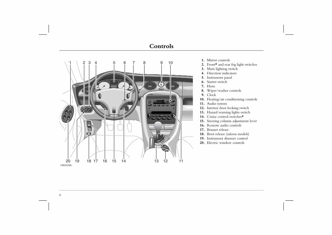
8 9 101 2 3 4 5 6 71. Mirror controls2. Front* and rear fog light switches3. Main lighting switch4. Direction indicators5. Instrument panel6. Starter switch7. Horn8. Wiper/washer controls9. Clock
10. Heating/air conditioning controls11. Audio system12. Interior door locking switch13. Hazard warning lights switch14. Cruise control switches* 15. Steering column adjustment lever16. Remote audio controls17. Bonnet release18. Boot release (saloon models)19. Instrument dimmer control20. Electric window controls
6
HB0229b
1113 121415161720 1819
Locks & Alarm
7
1Locks & Alarm YSTEM
fitted with a sophisticated electronic anti-theft alarm immobilisation system. There are also a number of curity features, some of which are selectable options.
ensure maximum security and operating convenience, ngly advised to gain a full understanding of the features ives available, by thoroughly reading this section of the
R MAXIMUM SECURITY ALWAYS CK THE VEHICLE USING THE REMOTE (except when passengers are to be left inside the car).
IMMOBILISATIONobilisation is an important aspect of the security
designed to safeguard the vehicle from theft, should rget to lock the doors and prevents the engine from unless the GENUINE handset key is inserted into the h. Engine immobilisation is automatic whenever any ing conditions occur:
conds after the starter switch has been turned off.y is removed from the starter switch.
e will be re-mobilised automatically whenever e handset key is inserted into the starter switch to the first position.
KEYS AND HANDSETSYou have been supplied with two remote handsets with integral keys which operate all locks.
Keep the spare handset key in a safe place - NOT IN THE VEHICLE!
The keys supplied with your car are programmed to your security system - they CANNOT be re-programmed and the engine cannot be started without a key programmed to your car. If a key is lost or broken, a replacement can only be ordered from an MG Rover dealer.
NOTE: MG Rover dealers do not stock spare keys, time has to be allowed for replacements to be programmed to your security system and then delivered to the dealer.
If you lose a key, contact your MG Rover dealer; a key reported lost will be deactivated. If the key is recovered, your dealer can have it reactivated.
ALARM SYour car is and engine additional seIn order to you are stroand alternathandbook.
NOTE: FOSUPERLOHANDSET
ENGINE Engine immsystem, it isthe driver fobeing startedstarter switcof the follow• Three se• If the ke
The enginthe genuinand turned
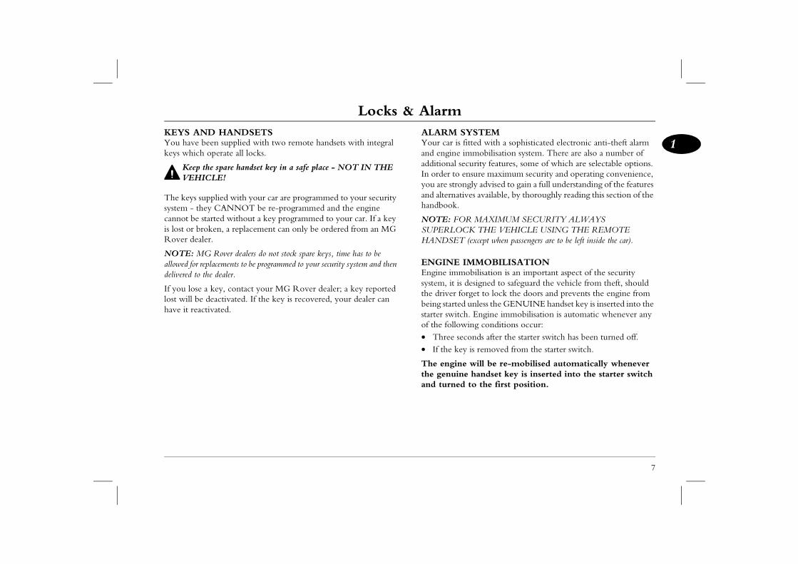
Locks & AlarmLOCKING THE CAR AND ARMING THE ALARMUsing the remote handset
Locking
With the remote handset:
rs, bonnet and luggage compartment. (padlock symbol) button once: are superlocked (see ‘Superlocking’, page 9)ic alarm activated (protects the doors, bonnet age compartment) space protection activated* indicator lights flash three times to confirm that rely locked and the anti-theft alarm indicator
nstrument panel) starts to flash.
and turn the door lock towards the rear of the
locked (not superlocked)ic alarm activated (protects the doors, bonnet age compartment) ERIOR SPACE PROTECTION indicator lights flash three times to confirm that rely locked and the anti-theft alarm indicator
nstrument panel) starts to flash.
8
While it is not necessary to point the handset at the car, the handset must be within range when the buttons are pressed. Note that the operating range may vary depending upon handset battery condition and may sometimes be limited by physical and geographical factors beyond your control. From a security point of view, it may not be wise to unlock unless you are close enough to visually confirm that the doors have locked.
1. Shut the doo2. Press the lock
• all doors• perimetr
and lugg• interior
3. The directionthe car is seculight (in the i
With the key:
1. Insert the keycar:
• all doors• perimetr
and lugg• NO INT
2. The directionthe car is seculight (in the i
H2698b
Locks & Alarm
9
1alarm indicator lightovides information about the status of the alarm llows:e alarm is armed: t flashes RAPIDLY while the alarm is arming itself. seconds, the light adjusts to a slower frequency and s to flash as an anti-theft deterrent until the alarm is . e alarm is partially armed: (mislock)t flashes SLOWLY for 10 seconds, then flashes as an t deterrent (as above) until the alarm is disarmed.e alarm has been triggered: ht flashes after the car is unlocked, this indicates that has been triggered during the driver’s absence. The
l flash for up to one minute or until the starter switch on.
sounds is triggered, the alarm sounder or vehicle horn will seconds before switching off and resetting itself to the tion status that existed prior to the alarm being silence the alarm, press either button on the remote
lock/unlock the door using the key.
Superlocking
For safety, NEVER use Superlocking if passengers are to remain inside the car - in an emergency they would not be able
to escape. Also, on cars fitted with interior space protection, any movement from inside the car would activate the alarm.
Provided all the doors are fully closed, the superlocking feature is activated automatically whenever the car is locked using the remote handset. Superlocking immobilises the interior door handles, thereby preventing an intruder from gaining entry by smashing a window and reaching inside the car to operate the door handles.
MislockIf the driver's door is not fully closed when the handset lock button is pressed, the alarm sounder or vehicle horn will sound once, indicating a mislock. In this case, none of the doors will lock and the alarm system will not be armed.
If a passenger door, bonnet or the luggage compartment is not fully closed when the handset lock button is pressed, the alarm sounder or vehicle horn will sound once, indicating a mislock. However, the ‘partial arming’ attributes of the security system will enable as much of the system to be armed as possible (all fully closed door, bonnet or luggage compartment apertures will be protected, but an open door will not!). As soon as the open aperture is closed, the system will automatically revert to an armed state.
NOTE: If a mislock occurs as a result of an open door, the superlocking and interior space protection features will not be activated, until the door is closed and the locking process is repeated.
Anti-theft The light prsystem, as fo• When th
The lighAfter tencontinuedisarmed
• When thThe lighanti-thef
• When thIf the ligthe alarmlight wilis turned
If the alarmIf the alarmsound for 30same protectriggered.Tohandset, or
Locks & AlarmUnlocking
With the remote handset:
Interior locking switch
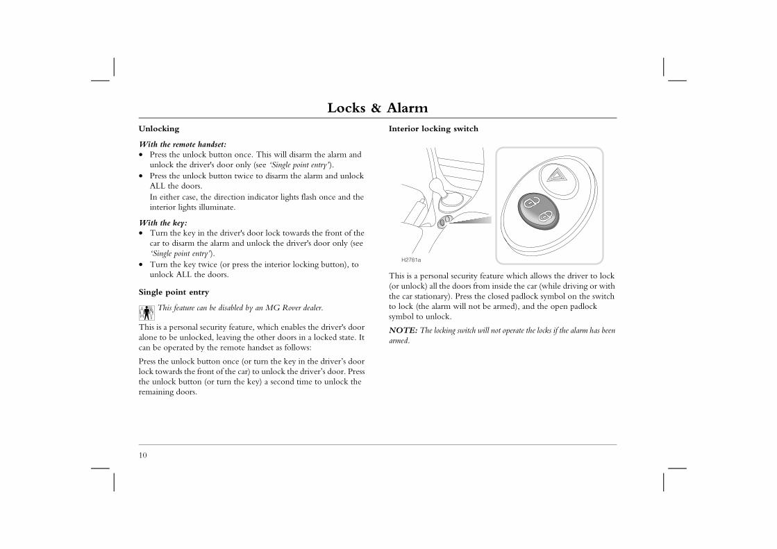
security feature which allows the driver to lock doors from inside the car (while driving or with . Press the closed padlock symbol on the switch will not be armed), and the open padlock
g switch will not operate the locks if the alarm has been
10
• Press the unlock button once. This will disarm the alarm and unlock the driver's door only (see ‘Single point entry’).
• Press the unlock button twice to disarm the alarm and unlock ALL the doors.In either case, the direction indicator lights flash once and the interior lights illuminate.
With the key:• Turn the key in the driver's door lock towards the front of the
car to disarm the alarm and unlock the driver's door only (see ‘Single point entry’).
• Turn the key twice (or press the interior locking button), to unlock ALL the doors.
Single point entry
This feature can be disabled by an MG Rover dealer.
This is a personal security feature, which enables the driver's door alone to be unlocked, leaving the other doors in a locked state. It can be operated by the remote handset as follows:
Press the unlock button once (or turn the key in the driver’s door lock towards the front of the car) to unlock the driver’s door. Press the unlock button (or turn the key) a second time to unlock the remaining doors.
This is a personal (or unlock) all thethe car stationary)to lock (the alarmsymbol to unlock.
NOTE: The lockinarmed.
H2781a
Locks & Alarm
11
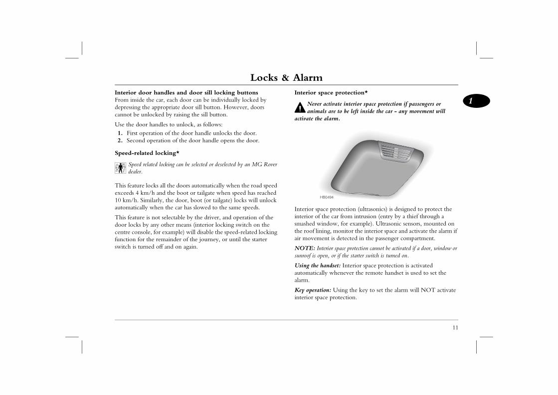
1ace protection*
activate interior space protection if passengers or s are to be left inside the car - any movement will alarm.
e protection (ultrasonics) is designed to protect the he car from intrusion (entry by a thief through a ndow, for example). Ultrasonic sensors, mounted on ng, monitor the interior space and activate the alarm if nt is detected in the passenger compartment.
erior space protection cannot be activated if a door, window or n, or if the starter switch is turned on.
andset: Interior space protection is activated ly whenever the remote handset is used to set the
on: Using the key to set the alarm will NOT activate e protection.
0494
Interior door handles and door sill locking buttonsFrom inside the car, each door can be individually locked by depressing the appropriate door sill button. However, doors cannot be unlocked by raising the sill button.
Use the door handles to unlock, as follows:1. First operation of the door handle unlocks the door.2. Second operation of the door handle opens the door.
Speed-related locking*
Speed related locking can be selected or deselected by an MG Rover dealer.
This feature locks all the doors automatically when the road speed exceeds 4 km/h and the boot or tailgate when speed has reached 10 km/h. Similarly, the door, boot (or tailgate) locks will unlock automatically when the car has slowed to the same speeds.
This feature is not selectable by the driver, and operation of the door locks by any other means (interior locking switch on the centre console, for example) will disable the speed-related locking function for the remainder of the journey, or until the starter switch is turned off and on again.
Interior sp
Never animal
activate the
Interior spacinterior of tsmashed withe roof liniair moveme
NOTE: Intsunroof is ope
Using the hautomaticalalarm.
Key operatiinterior spac
HB
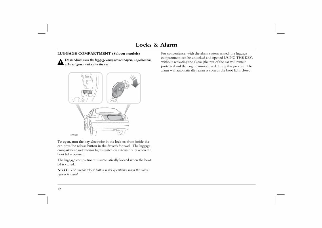
Locks & AlarmLUGGAGE COMPARTMENT (Saloon models)
Do not drive with the luggage compartment open, as poisonous
For convenience, with the alarm system armed, the luggage compartment can be unlocked and opened USING THE KEY, without activating the alarm (the rest of the car will remain
engine immobilised during this process). The tically rearm as soon as the boot lid is closed.
12
exhaust gases will enter the car.
To open, turn the key clockwise in the lock or, from inside the car, press the release button in the driver's footwell. The luggage compartment and interior lights switch on automatically when the boot lid is opened.
The luggage compartment is automatically locked when the boot lid is closed.
NOTE: The interior release button is not operational when the alarm system is armed.
protected and thealarm will automa
HB0511
Locks & Alarm
13
1
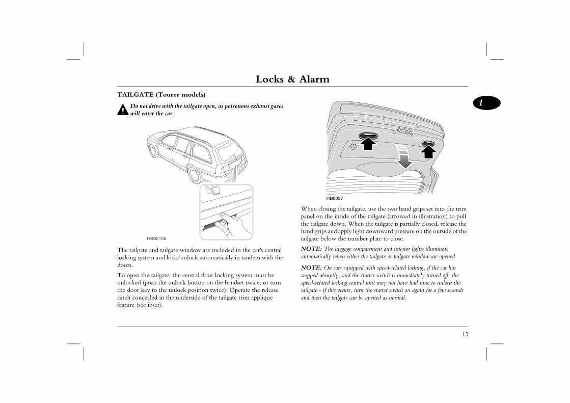
g the tailgate, use the two hand grips set into the trim inside of the tailgate (arrowed in illustration) to pull
down. When the tailgate is partially closed, release the nd apply light downward pressure on the outside of the w the number plate to close.
e luggage compartment and interior lights illuminate when either the tailgate or tailgate window are opened.
cars equipped with speed-related locking, if the car has tly, and the starter switch is immediately turned off, the locking control unit may not have had time to unlock the is occurs, turn the starter switch on again for a few seconds tailgate can be opened as normal.
0037
TAILGATE (Tourer models)
Do not drive with the tailgate open, as poisonous exhaust gases will enter the car.
The tailgate and tailgate window are included in the car's central locking system and lock/unlock automatically in tandem with the doors.
To open the tailgate, the central door locking system must be unlocked (press the unlock button on the handset twice, or turn the door key to the unlock position twice). Operate the release catch concealed in the underside of the tailgate trim applique feature (see inset).
When closinpanel on thethe tailgate hand grips atailgate belo
NOTE: Thautomatically
NOTE: Onstopped abrupspeed-related tailgate - if thand then the
HB0510a
HB
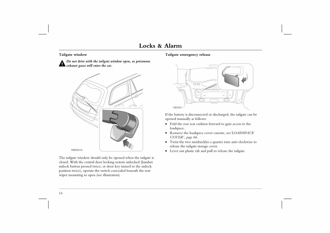
Locks & AlarmTailgate window
Do not drive with the tailgate window open, as poisonous
Tailgate emergency release
sconnected or discharged, the tailgate can be as follows:at cushion forward to gain access to the
adspace cover cassette, see‘LOADSPACE 66.
turnbuckles a quarter turn anti-clockwise to ate storage cover.ic tab and pull to release the tailgate.
14
exhaust gases will enter the car.
The tailgate window should only be opened when the tailgate is closed. With the central door locking system unlocked (handset unlock button pressed twice, or door key turned to the unlock position twice), operate the switch concealed beneath the rear wiper mounting to open (see illustration).
If the battery is diopened manually • Fold the rear se
loadspace.• Remove the lo
COVER’, page• Twist the two
release the tailg• Lever out plastHB0031b
HB0500
Locks & Alarm
15
1
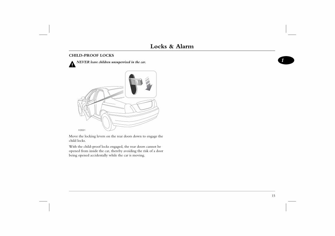
CHILD-PROOF LOCKSNEVER leave children unsupervised in the car.
Move the locking levers on the rear doors down to engage the child locks.
With the child-proof locks engaged, the rear doors cannot be opened from inside the car, thereby avoiding the risk of a door being opened accidentally while the car is moving.
H2691
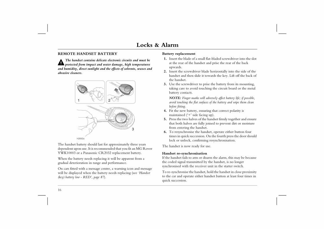
Locks & AlarmREMOTE HANDSET BATTERY
The handset contains delicate electronic circuits and must be
Battery replacement1. Insert the blade of a small flat-bladed screwdriver into the slot
the handset and prise the rear of the back
ewdriver blade horizontally into the side of the hen slide it towards the key. Lift off the back of
driver to prise the battery from its mounting, avoid touching the circuit board or the metal cts.
er marks will adversely affect battery life; if possible, the flat surfaces of the battery and wipe them clean
attery, ensuring that correct polarity is +’ side facing up). halves of the handset firmly together and ensure ves are fully joined to prevent dirt or moisture the handset.nise the handset, operate either button four succession. On the fourth press the door should k, confirming resynchronisation.
w ready for use.
hronisation to arm or disarm the alarm, this may be because ransmitted by the handset, is no longer the receiver unit in the starter switch.
the handset, hold the handset in close proximity rate either handset button at least four times in
16
protected from impact and water damage, high temperatures and humidity, direct sunlight and the effects of solvents, waxes and abrasive cleaners.
The handset battery should last for approximately three years dependent upon use. It is recommended that you fit an MG Rover YWK10003 or a Panasonic CR2032 replacement battery.
When the battery needs replacing it will be apparent from a gradual deterioration in range and performance.
On cars fitted with a message centre, a warning icon and message will be displayed when the battery needs replacing (see ‘Handset (key) battery low - RED’, page 87).
at the rear ofupwards.
2. Insert the scrhandset and tthe handset.
3. Use the screwtaking care tobattery conta
NOTE: Fingavoid touchingbefore fitting.
4. Fit the new bmaintained (‘
5. Press the twothat both halfrom entering
6. To resynchrotimes in quicklock or unloc
The handset is no
Handset re-syncIf the handset failsthe coded signal tsynchronised with
To re-synchroniseto the car and opequick succession.
1
3
H2692a
2
Seats
17
1Seats STRAINTS
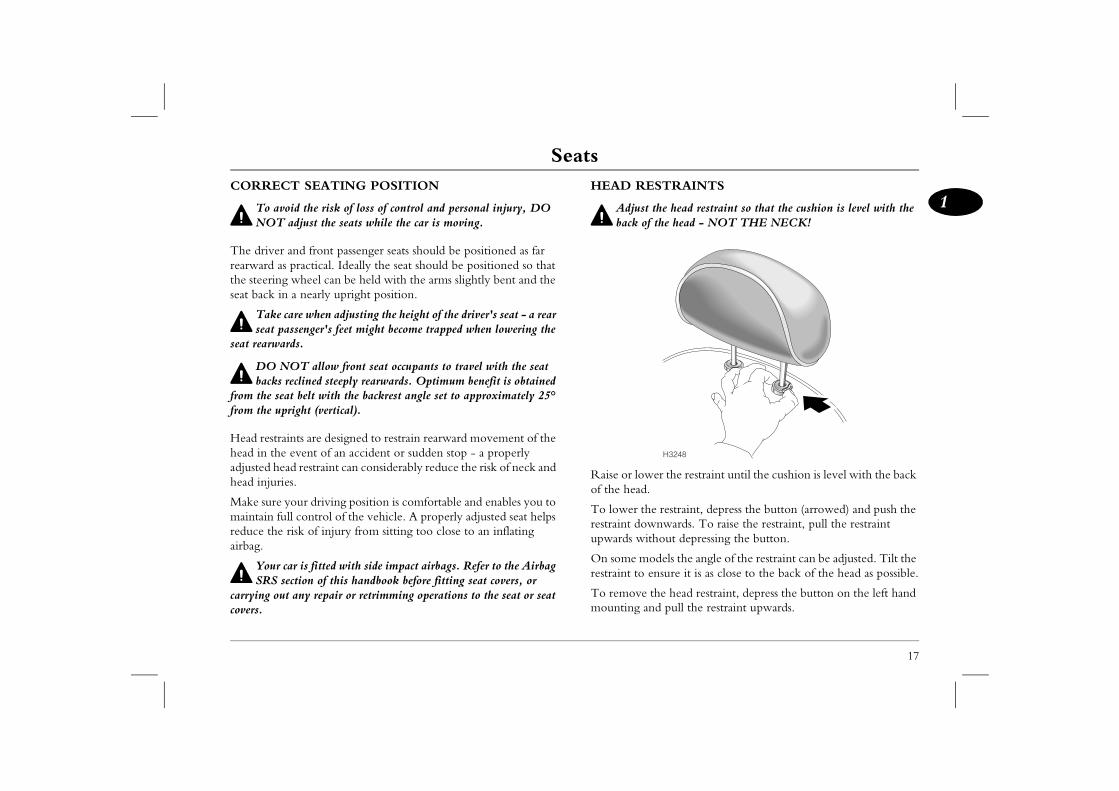
the head restraint so that the cushion is level with the the head - NOT THE NECK!
er the restraint until the cushion is level with the back
e restraint, depress the button (arrowed) and push the nwards. To raise the restraint, pull the restraint
thout depressing the button.
odels the angle of the restraint can be adjusted. Tilt the ensure it is as close to the back of the head as possible.
the head restraint, depress the button on the left hand nd pull the restraint upwards.
H3248
CORRECT SEATING POSITION
To avoid the risk of loss of control and personal injury, DO NOT adjust the seats while the car is moving.
The driver and front passenger seats should be positioned as far rearward as practical. Ideally the seat should be positioned so that the steering wheel can be held with the arms slightly bent and the seat back in a nearly upright position.
Take care when adjusting the height of the driver's seat - a rear seat passenger's feet might become trapped when lowering the
seat rearwards.
DO NOT allow front seat occupants to travel with the seat backs reclined steeply rearwards. Optimum benefit is obtained
from the seat belt with the backrest angle set to approximately 25° from the upright (vertical).
Head restraints are designed to restrain rearward movement of the head in the event of an accident or sudden stop - a properly adjusted head restraint can considerably reduce the risk of neck and head injuries.
Make sure your driving position is comfortable and enables you to maintain full control of the vehicle. A properly adjusted seat helps reduce the risk of injury from sitting too close to an inflating airbag.
Your car is fitted with side impact airbags. Refer to the Airbag SRS section of this handbook before fitting seat covers, or
carrying out any repair or retrimming operations to the seat or seat covers.
HEAD RE
Adjustback of
Raise or lowof the head.
To lower threstraint dowupwards wi
On some mrestraint to
To remove mounting a
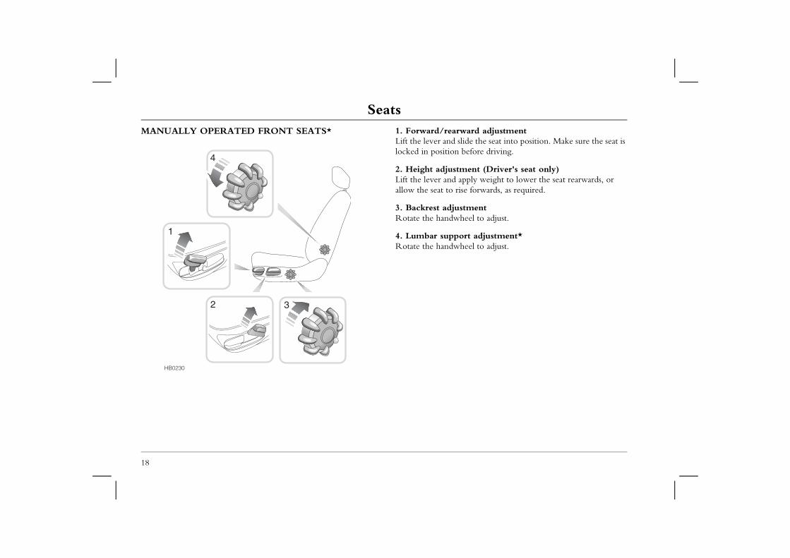
SeatsMANUALLY OPERATED FRONT SEATS* 1. Forward/rearward adjustment
Lift the lever and slide the seat into position. Make sure the seat is locked in position before driving.
ment (Driver's seat only)apply weight to lower the seat rearwards, or ise forwards, as required.
stmentheel to adjust.
ort adjustment*heel to adjust.
18
2. Height adjustLift the lever and allow the seat to r
3. Backrest adjuRotate the handw
4. Lumbar suppRotate the handw
HB0230
1
32
4
Seats
19
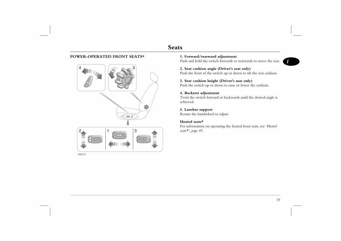
1/rearward adjustmentld the switch forwards or rearwards to move the seat.
hion angle (Driver's seat only)nt of the switch up or down to tilt the seat cushion.
hion height (Driver's seat only)itch up or down to raise or lower the cushion.
t adjustmentitch forward or backwards until the desired angle is
supporthandwheel to adjust.
ts*tion on operating the heated front seats, see ‘Heated 45.
POWER-OPERATED FRONT SEATS* 1. ForwardPush and ho
2. Seat cusPush the fro
3. Seat cusPush the sw
4. BackresTwist the swachieved.
5. LumbarRotate the
Heated seaFor informaseats*’, page
HB0231
1 3
54
2
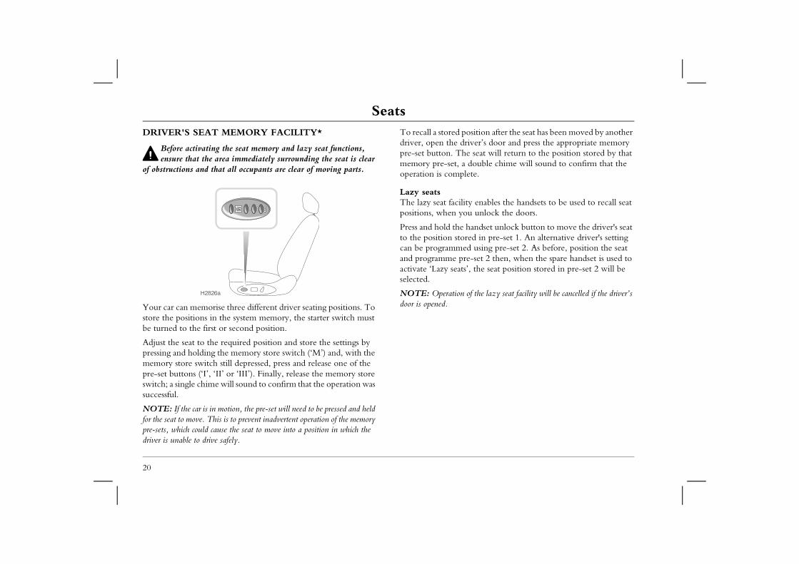
SeatsDRIVER'S SEAT MEMORY FACILITY*
Before activating the seat memory and lazy seat functions,
To recall a stored position after the seat has been moved by another driver, open the driver’s door and press the appropriate memory pre-set button. The seat will return to the position stored by that
double chime will sound to confirm that the lete.
ity enables the handsets to be used to recall seat ou unlock the doors.
handset unlock button to move the driver's seat red in pre-set 1. An alternative driver's setting ed using pre-set 2. As before, position the seat re-set 2 then, when the spare handset is used to s’, the seat position stored in pre-set 2 will be
of the lazy seat facility will be cancelled if the driver’s
20
ensure that the area immediately surrounding the seat is clear of obstructions and that all occupants are clear of moving parts.
Your car can memorise three different driver seating positions. To store the positions in the system memory, the starter switch must be turned to the first or second position.
Adjust the seat to the required position and store the settings by pressing and holding the memory store switch (‘M’) and, with the memory store switch still depressed, press and release one of the pre-set buttons (‘I’, ‘II’ or ‘III’). Finally, release the memory store switch; a single chime will sound to confirm that the operation was successful.
NOTE: If the car is in motion, the pre-set will need to be pressed and held for the seat to move. This is to prevent inadvertent operation of the memory pre-sets, which could cause the seat to move into a position in which the driver is unable to drive safely.
memory pre-set, aoperation is comp
Lazy seatsThe lazy seat facilpositions, when y
Press and hold theto the position stocan be programmand programme pactivate ‘Lazy seatselected.
NOTE: Operationdoor is opened.
H2826a
Seat Belts
21
1Seat Belts T allow foreign matter (particularly sugary food and
ticles) to enter the seat belt locks - such substances can e locks inoperative.
countries, all occupants are required by law to wear a unless they have been issued with a medical n certificate.regnancy, women should wear the lap belt across the w the baby, with the diagonal belt passing across the , between the breasts and to one side of the baby - if in onsult a doctor.
rbag supplementary restraint system (SRS) is designed to the overall effectiveness of the seat belts. It does not . SEAT BELTS MUST ALWAYS BE WORN!
SEAT BELT SAFETYThe seat belts fitted to your vehicle are intended for use by adult sized occupants. Each belt should be used by one occupant only.
Observe the following precautions:• DO make sure ALL passengers are securely strapped in at all
times - even for the shortest journeys. • ALWAYS adjust seat belts to eliminate any slack in the
webbing. DO NOT slacken the webbing by holding the belt away from the body - to be fully effective, the seat belt must remain in full contact with the body at all times.
• ALWAYS fit the lap strap as low on the hips as possible (never across the abdomen), and ensure that the diagonal belt passes across the shoulder without slipping off or pressing on the neck.
• DO NOT wear seat belts over hard, sharp or fragile items in clothing, such as pens, keys, spectacles etc.
• Always replace a seat belt assembly that has withstood the strain of a severe vehicle impact, or if the webbing shows signs of fraying.
• Where possible use the seat belts to secure large items of luggage that are to be carried on the seats - in the event of an accident, unsecured items become flying missiles capable of causing serious injury.
• DO NOT use a seat belt that is twisted or obstructed in any way that could impede its smooth operation.
• DO NOT allow front seat occupants to travel with the seat backs reclined steeply rearwards. Optimum benefit is obtained from the seat belt with the seat back angle set to approximately 25° from the upright (vertical) position.
• DO NOdrink parrender th
• In most seat belt,exemptio
• During phips beloshoulderdoubt, c
The aito add
replace them
Seat BeltsSEAT BELTS
Ensure that all seat belts are worn correctly - an improperly
Seat belts are designed to bear upon the bony structure of the body (pelvis, chest and shoulders) and can only be worn safely with the seats in a near-upright position; DO NOT allow the front
l with the seat steeply reclined (see ‘Seating .
ltn on the seat belt buckle.
e height adjustmentlihood of injury in an accident, the height of the er anchorage adjusts automatically as the seat is ards or backwards. The height CANNOT BE UALLY!
22
worn seat belt increases the risk of death or serious injury in the event of a collision. Read the instructions below and the advice contained under the heading ‘Seat belt safety’ on a previous page.
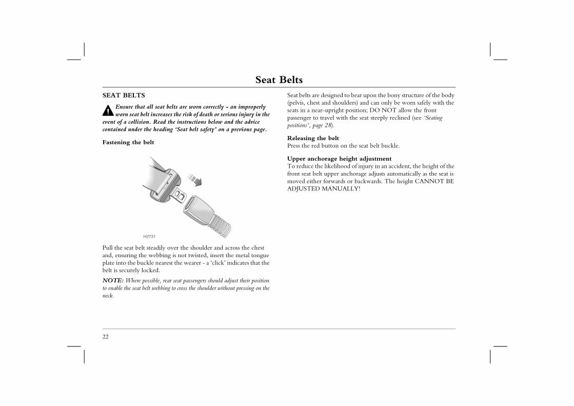
Fastening the belt
Pull the seat belt steadily over the shoulder and across the chest and, ensuring the webbing is not twisted, insert the metal tongue plate into the buckle nearest the wearer - a ‘click’ indicates that the belt is securely locked.
NOTE: Where possible, rear seat passengers should adjust their position to enable the seat belt webbing to cross the shoulder without pressing on the neck.
passenger to travepositions’, page 28)
Releasing the bePress the red butto
Upper anchoragTo reduce the likefront seat belt uppmoved either forwADJUSTED MAN
H2731
Seat Belts
23
1of vehiclesour car, be sure to inform the new owner that the ted with pre-tensioners, and make the new owner he pre-tensioners must be examined and replaced by rsonnel after a period of 15 years.
s to be scrapped, unactivated pre-tensioners are ery dangerous and must be safely deployed in a nvironment by qualified personnel, before it is
SEAT BELT PRE-TENSIONERS
The seat belt pre-tensioners will only be activated once and then MUST BE REPLACED by an MG Rover dealer.
Failure to replace the pre-tensioners will reduce the efficiency of the car's front restraint systems.
The seat belt pre-tensioners activate in conjunction with the airbag SRS to provide additional protection in the event of a severe frontal, rear or side impact on the vehicle (see ‘HOW THE AIRBAG SRS OPERATES’, page 29). The pre-tensioners automatically retract the seat belts. This reduces any slack in both the lap and diagonal portions of the belts, thereby reducing forward movement of the belt wearer in the event of a severe collision.
NOTE: The seat belt pre-tensioners will NOT be activated by minor impacts.
The airbag SRS warning light on the instrument panel, will alert you to any malfunction of the seat belt pre-tensioners (see ‘Airbag SRS warning light’, page 31).
NOTE: After any impact, always have the seat belts and pre-tensioners checked and, if necessary, replaced by an MG Rover dealer.
If the pre-tensioners have been activated, the seat belts will still function as restraints, and must be worn in the event that the vehicle remains in a driveable condition.
Disposing If you sell yvehicle is fitaware that tqualified pe
If your car ipotentially vcontrolled escrapped.
Seat BeltsCARING FOR SEAT BELTS
Always replace a seat belt assembly where the webbing shows
24
signs of fraying.
Regularly inspect the belt webbing for signs of fraying, cuts and wear; also pay particular attention to the condition of the fixing points and adjusters.
Do not bleach or dye the webbing and avoid contaminating the webbing with polish, oil or chemicals (see ‘CLEANING THE INTERIOR’, page 211).
Three tests for checking seat belts1. With the seat belt fastened, give the webbing nearest the
buckle a quick pull - the buckle should remain securely locked.
2. With the seat belt unfastened, unreel the webbing to the limit of its travel. Check that unreeling is free from snags and snatches and further check the webbing for visual signs of wear or fraying.Allow the webbing to retract, checking that retraction is smooth, continuous and complete.
3. With the webbing half unreeled, hold the tongue plate and give it a quick forward pull - the mechanism must lock automatically and prevent any further unreeling.
If a seat belt should fail any of these tests, contact your dealer immediately.
Child Restraints
25
1Child Restraints
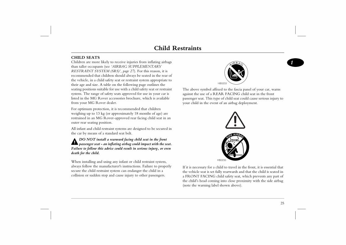
symbol affixed to the fascia panel of your car, warns se of a REAR FACING child seat in the front
at. This type of child seat could cause serious injury to n the event of an airbag deployment.
sary for a child to travel in the front, it is essential that seat is set fully rearwards and that the child is seated in FACING child safety seat, which prevents any part of ead coming into close proximity with the side airbag arning label shown above).
AIRBAG
HB0233
SIDE AIRBAG
HB0235
CHILD SEATSChildren are more likely to receive injuries from inflating airbags than taller occupants (see ‘AIRBAG SUPPLEMENTARY RESTRAINT SYSTEM (SRS)’, page 27). For this reason, it is recommended that children should always be seated in the rear of the vehicle, in a child safety seat or restraint system appropriate to their age and size. A table on the following page outlines the seating positions suitable for use with a child safety seat or restraint system. The range of safety seats approved for use in your car is listed in the MG Rover accessories brochure, which is available from your MG Rover dealer.
For optimum protection, it is recommended that children weighing up to 13 kg (or approximately 18 months of age) are restrained in an MG Rover-approved rear facing child seat in an outer rear seating position.
All infant and child restraint systems are designed to be secured in the car by means of a standard seat belt.
DO NOT install a rearward facing child seat in the front passenger seat - an inflating airbag could impact with the seat.
Failure to follow this advice could result in serious injury, or even death for the child.
When installing and using any infant or child restraint system, always follow the manufacturer's instructions. Failure to properly secure the child restraint system can endanger the child in a collision or sudden stop and cause injury to other passengers.
The above against the upassenger seyour child i
If it is necesthe vehicle a FRONT the child’s h(note the w
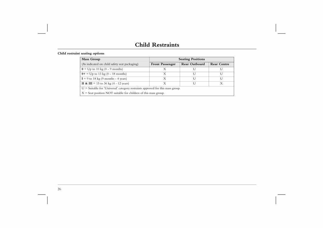
Child RestraintsChild restraint seating options
Mass Group Seating Positions
r Outboard Rear Centre
U U
U U
U U
U X
26
(As indicated on child safety seat packaging) Front Passenger Rea
0 = Up to 10 kg (0 - 9 months) X
0+ = Up to 13 kg (0 - 18 months) X
I = 9 to 18 kg (9 months - 4 years) X
II & III = 15 to 36 kg (4 - 12 years) X
U = Suitable for ‘Universal’ category restraints approved for this mass group.
X = Seat position NOT suitable for children of this mass group.
Airbag SRS
27
1Airbag SRS e front seat occupants are correctly seated, with seat
ly worn, the airbags will provide additional protection and facial areas in the event of the car receiving a al impact, and to the side of the body facing the impact, de collision occurs.
pact protection (where fitted) will afford additional o the side of the head facing the impact, in the event ide collision.
allow a front seat passenger to obstruct the operation of ag by placing feet, knees or any other part of the person, objects in contact with, or in close proximity to, an le.
irbags are located in the centre pad of the steering n the fascia panel above the glovebox. Side airbags are n the backrest padding on the outward side of both he side head impact protection airbags (if fitted) are
ind the roof lining and front pillar finishers (where
OT attach or position items on, or close to the roof or front pillar and ‘B’ post finishers, or to an airbag g wheel centre pad or fascia panel), which could
h the inflation of the airbag or, if the airbag inflates, be side the car causing injury to the occupants.
AIRBAG SUPPLEMENTARY RESTRAINT SYSTEM (SRS)
The airbag SRS provides ADDITIONAL protection in a severe impact only. It does not replace the need to wear a seat
belt.
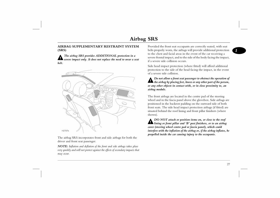
The airbag SRS incorporates front and side airbags for both the driver and front seat passenger.
NOTE: Inflation and deflation of the front and side airbags takes place very quickly and will not protect against the effects of secondary impacts that may occur.
Provided thbelts properto the chestsevere frontif a severe si
Side head improtection tof a severe s
Do notthe airb
or any otherairbag modu
The front awheel and ipositioned ifront seats. Tsituated behshown).
DO Nlining
cover (steerininterfere witpropelled in
H2797b
Airbag SRSAirbag deploymentTo ensure correct deployment of the airbags, it is essential that obstructions are not allowed to intervene between an airbag and
Seating positions
To minimise the risk of accidental injury from inflating belts should be correctly worn at all times. In er and front seat passenger should adjust their maximum practical distance from the front nsure that a gap is maintained between the upper of the vehicle, to enable unobstructed inflation of
e optimum protection in the event of a severe sary for the airbags to deploy with considerable
can cause facial abrasions and other injuries if o close to the airbag at the time of its
28
the occupant. The following are examples of the type of obstructions that could either, impede correct operation of the airbags, or jeopardise personal safety in the event of an airbag deployment:• Accessories attached to or obscuring an airbag cover, including
the roof lining, front pillar and ‘B’ post finishers and the part of the front seat containing the side airbag or the pillar between front and rear doors.
• Items of hand luggage, or other objects placed on an airbag cover.
• Feet, knees or any other part of the anatomy in contact with, or in close proximity to, a front airbag cover.
• Items on the shelf below the front passenger airbag that are likely to impede airbag operation in the event of an impact.
• Head, arms or any part of the anatomy in contact with, or in close proximity to, a side airbag.
• Items of clothing or cushions draped over the part of the front seat containing the airbag or hanging from the grab handle attached to the roof.
• Non-approved seat covers fitted over a front seat (in particular, be aware that seat covers approved for other cars will NOT be suitable for this car). If in doubt, seek advice from an MG Rover dealer.
airbags, seat addition, both drivseat to provide theairbags, and also etorso and the side the side airbags.
In order to providimpact, it is necesspeed.
An inflating airbagthe occupant is todeployment.
Airbag SRS
29
1
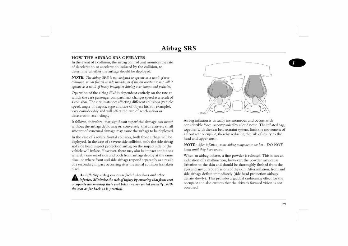
tion is virtually instantaneous and occurs with force, accompanied by a loud noise. The inflated bag,
th the seat belt restraint system, limit the movement of occupant, thereby reducing the risk of injury to the per torso.
er inflation, some airbag components are hot - DO NOT ey have cooled.
rbag inflates, a fine powder is released. This is not an f a malfunction, however, the powder may cause the skin and should be thoroughly flushed from the cuts or abrasions of the skin. After inflation, front and deflate immediately (side head protection airbags ly). This provides a gradual cushioning effect for the d also ensures that the driver's forward vision is not
98a
HOW THE AIRBAG SRS OPERATESIn the event of a collision, the airbag control unit monitors the rate of deceleration or acceleration induced by the collision, to determine whether the airbags should be deployed.
NOTE: The airbag SRS is not designed to operate as a result of rear collisions, minor frontal or side impacts, or if the car overturns; nor will it operate as a result of heavy braking or driving over bumps and potholes.
Operation of the airbag SRS is dependent entirely on the rate at which the car's passenger compartment changes speed as a result of a collision. The circumstances affecting different collisions (vehicle speed, angle of impact, type and size of object hit, for example), vary considerably and will affect the rate of acceleration or deceleration accordingly.
It follows, therefore, that significant superficial damage can occur without the airbags deploying or, conversely, that a relatively small amount of structural damage may cause the airbags to be deployed.
In the case of a severe frontal collision, both front airbags will be deployed. In the case of a severe side collision, only the side airbag and side head impact protection airbag on the impact side of the vehicle will inflate. However, there may also be impact conditions whereby one set of side and both front airbags deploy at the same time, or where front and side airbags respond separately as a result of a secondary impact occurring after the initial collision has taken place.
An inflating airbag can cause facial abrasions and other injuries. Minimise the risk of injury by ensuring that front seat
occupants are wearing their seat belts and are seated correctly, with the seat as far back as is practical.
Airbag inflaconsiderabletogether wia front seat head and up
NOTE: Afttouch until th
When an aiindication oirritation toeyes and anyside airbags deflate slowoccupant anobscured.
H27
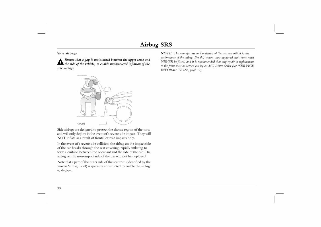
Airbag SRSSide airbags
Ensure that a gap is maintained between the upper torso and
NOTE: The manufacture and materials of the seat are critical to the performance of the airbag. For this reason, non-approved seat covers must NEVER be fitted, and it is recommended that any repair or replacement
carried out by an MG Rover dealer (see ‘SERVICE ’, page 32).
30
the side of the vehicle, to enable unobstructed inflation of the side airbags.
Side airbags are designed to protect the thorax region of the torso and will only deploy in the event of a severe side impact. They will NOT inflate as a result of frontal or rear impacts only.
In the event of a severe side collision, the airbag on the impact side of the car breaks through the seat covering, rapidly inflating to form a cushion between the occupant and the side of the car. The airbag on the non-impact side of the car will not be deployed
Note that a part of the outer side of the seat trim (identified by the woven ‘airbag’ label) is specially constructed to enable the airbag to deploy.
to the front seats be INFORMATION
H2799b
Airbag SRS
31
1S warning lightight, mounted on the instrument panel, will alert you nction of the airbag SRS and seat belt pre-tensioners. ill illuminate as a bulb and system check when the h is turned to the second position and will extinguish imately four seconds. The system should always be a dealer if any of the following symptoms occur:ning light fails to illuminate when the starter switch is the second position.
ning light fails to extinguish within approximately four after the starter switch is turned to the second position.ning light illuminates while the car is being driven.
Side head impact protection*
NOTE: For the side head impact airbags to deploy correctly, the roof lining and front pillar trim must be undamaged and fitted correctly. Any damage or suspect fitting should be referred to an MG Rover dealer for examination.
Side head impact airbags are designed to protect the head in the event of a severe side impact only. They will NOT inflate as a result of frontal or rear impacts alone.
The side head impact protection modules are located behind the roof lining and front pillar finisher, above the doors. In the event of a severe side collision, the airbag pushes out from behind the roof lining and front pillar finisher as it inflates. The side head impact airbag remains inflated for longer than the other airbags, to provide additional head protection in the event of a secondary impact.
Airbag SRA warning lto any malfuThe light wstarter switcafter approxchecked by • The war
turned to• The war
seconds • The war
Airbag SRSSERVICE INFORMATIONAfter 15 years from the initial date of registration (or installation date of a replacement airbag SRS), some components will need to
Disposing of the vehicleIf you sell your vehicle, be sure to inform the new owner that the vehicle has an airbag SRS and make the new owner aware of the
lacement date.
be scrapped; uninflated airbags are potentially d must be safely deployed in a controlled ualified personnel, before a vehicle is scrapped.
32
be replaced by an MG Rover dealer, who should stamp and sign the appropriate page of the Service History section of this book once the work has been completed.
In addition, ALWAYS contact your dealer if;• an airbag inflates.• the front or side of the vehicle is damaged (even if the
corresponding airbag has not inflated).• any part of an airbag module covers show signs of deterioration
or damage.
The components of the airbag SRS are sensitive to electrical and physical interference; it is recommended that you ALWAYS seek the assistance of an MG Rover dealer to carry out any of the following:• Removal or repair of any wiring or component in the vicinity
of the airbag SRS components, including: the steering wheel, steering column, front seats, fascia and instrument panel.
• Installation of electronic equipment such as a mobile phone, two-way radio or in-car entertainment system.
• Attachment of accessories to, or modification of, the front or side of the vehicle.
• Removal, replacement, or retrimming of a front seat or seat cover.
DO NOT service, repair, replace, modify or tamper with any part of the airbag SRS, or wiring in the vicinity of an airbag
SRS component; this could cause the system to activate, resulting in personal injury.
airbag module rep
If the vehicle is tovery dangerous anenvironment by q
Steering Column
33
1Steering Column push the steering wheel closer to, or further away
our body. comfortable driving position has been selected, pull king lever fully up to lock the steering column into its sition.
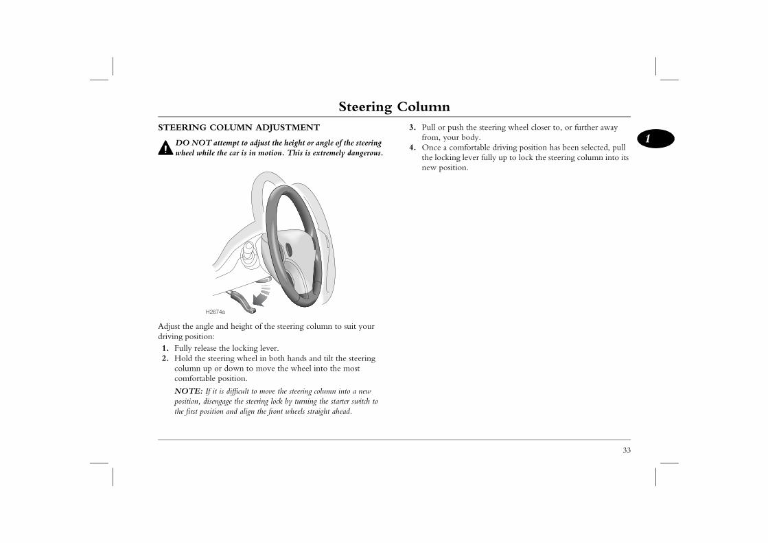
STEERING COLUMN ADJUSTMENT
DO NOT attempt to adjust the height or angle of the steering wheel while the car is in motion. This is extremely dangerous.
Adjust the angle and height of the steering column to suit your driving position:1. Fully release the locking lever.2. Hold the steering wheel in both hands and tilt the steering
column up or down to move the wheel into the most comfortable position.
NOTE: If it is difficult to move the steering column into a new position, disengage the steering lock by turning the starter switch to the first position and align the front wheels straight ahead.
3. Pull orfrom, y
4. Once athe locnew po
H2674a
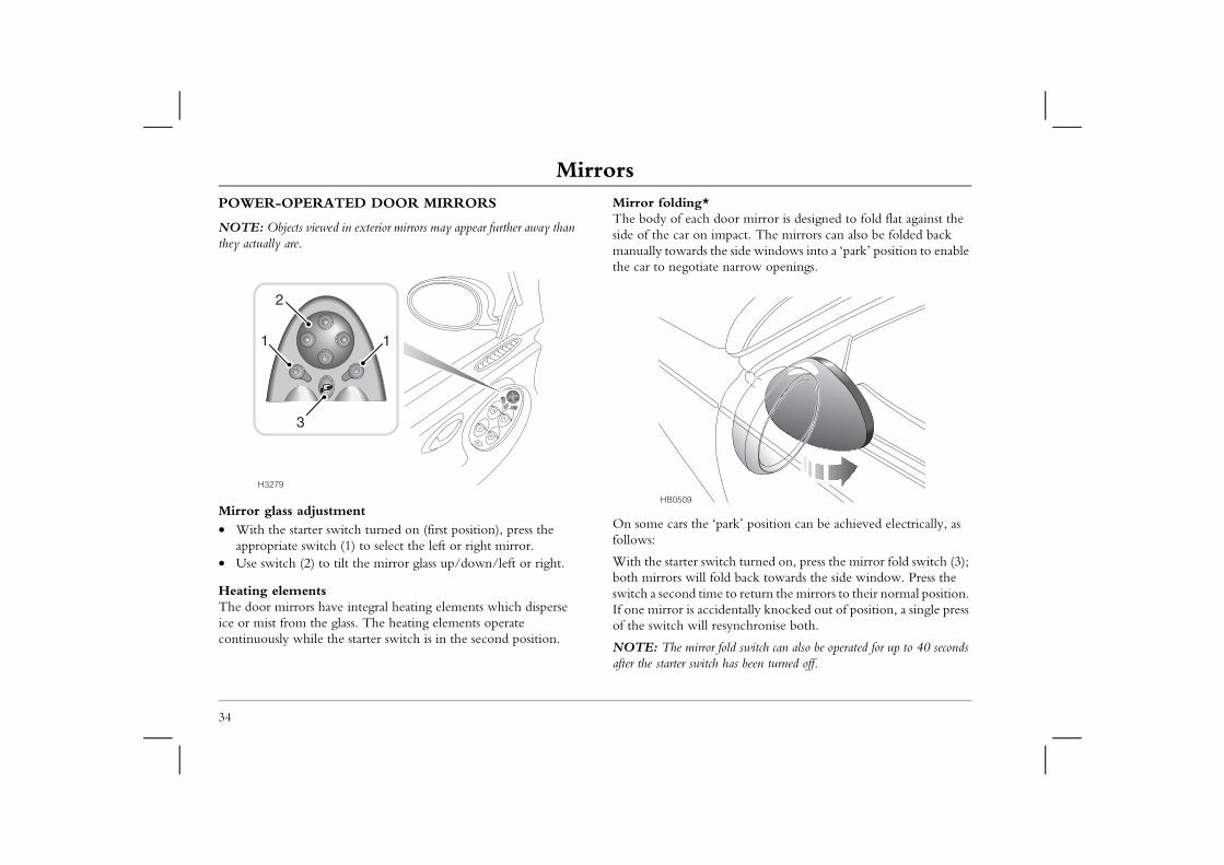
MirrorsMirrorsPOWER-OPERATED DOOR MIRRORS
NOTE: Objects viewed in exterior mirrors may appear further away than
Mirror folding*The body of each door mirror is designed to fold flat against the side of the car on impact. The mirrors can also be folded back
the side windows into a ‘park’ position to enable te narrow openings.
‘park’ position can be achieved electrically, as
itch turned on, press the mirror fold switch (3); fold back towards the side window. Press the e to return the mirrors to their normal position.
cidentally knocked out of position, a single press resynchronise both.
r fold switch can also be operated for up to 40 seconds h has been turned off.
34
they actually are.
Mirror glass adjustment• With the starter switch turned on (first position), press the
appropriate switch (1) to select the left or right mirror.• Use switch (2) to tilt the mirror glass up/down/left or right.
Heating elementsThe door mirrors have integral heating elements which disperse ice or mist from the glass. The heating elements operate continuously while the starter switch is in the second position.
manually towards the car to negotia
On some cars thefollows:
With the starter swboth mirrors will switch a second timIf one mirror is acof the switch will
NOTE: The mirroafter the starter switc
H3279
1 1
3
2
HB0509
Mirrors
35
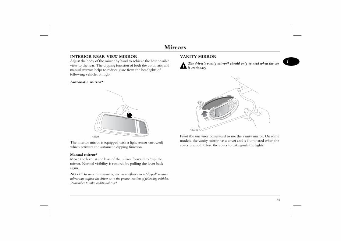
1MIRROR
iver’s vanity mirror* should only be used when the car onary
n visor downward to use the vanity mirror. On some vanity mirror has a cover and is illuminated when the ed. Close the cover to extinguish the lights.
INTERIOR REAR-VIEW MIRRORAdjust the body of the mirror by hand to achieve the best possible view to the rear. The dipping function of both the automatic and manual mirrors helps to reduce glare from the headlights of following vehicles at night.
Automatic mirror*
The interior mirror is equipped with a light sensor (arrowed) which activates the automatic dipping function.
Manual mirror*Move the lever at the base of the mirror forward to ‘dip’ the mirror. Normal visibility is restored by pulling the lever back again.
NOTE: In some circumstances, the view reflected in a ‘dipped’ manual mirror can confuse the driver as to the precise location of following vehicles. Remember to take additional care!
VANITY
The dris stati
Pivot the sumodels, thecover is rais
H2829
H2936a
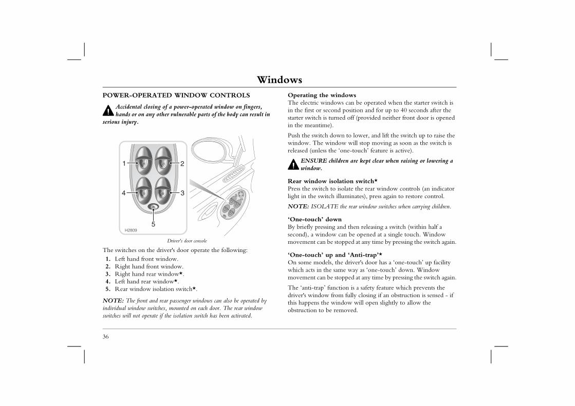
WindowsWindowsPOWER-OPERATED WINDOW CONTROLS
Accidental closing of a power-operated window on fingers,
Operating the windowsThe electric windows can be operated when the starter switch is in the first or second position and for up to 40 seconds after the
rned off (provided neither front door is opened
own to lower, and lift the switch up to raise the dow will stop moving as soon as the switch is e ‘one-touch’ feature is active).
ildren are kept clear when raising or lowering a
olation switch* isolate the rear window controls (an indicator illuminates), press again to restore control.
E the rear window switches when carrying children.
wn and then releasing a switch (within half a can be opened at a single touch. Window
stopped at any time by pressing the switch again.
and ‘Anti-trap’* the driver's door has a ‘one-touch’ up facility same way as ‘one-touch’ down. Window stopped at any time by pressing the switch again.
ction is a safety feature which prevents the om fully closing if an obstruction is sensed - if indow will open slightly to allow the
removed.
36
hands or on any other vulnerable parts of the body can result in serious injury.
Driver's door console
The switches on the driver's door operate the following:1. Left hand front window.2. Right hand front window.3. Right hand rear window*.4. Left hand rear window*.5. Rear window isolation switch*.
NOTE: The front and rear passenger windows can also be operated by individual window switches, mounted on each door. The rear window switches will not operate if the isolation switch has been activated.
starter switch is tuin the meantime).
Push the switch dwindow. The winreleased (unless th
ENSURE chwindow.
Rear window isPress the switch tolight in the switch
NOTE: ISOLAT
‘One-touch’ doBy briefly pressingsecond), a windowmovement can be
‘One-touch’ upOn some models,which acts in the movement can be
The ‘anti-trap’ fundriver's window frthis happens the wobstruction to be
5
21
34
H2809
Sunroof
37
1Sunroof f opens and closes in two separate phases, as follows:
T the roof: sunroof either open or closed, press and release the ortion of the sunroof button. The sunroof will cally close (if open) and then tilt upwards. Sunroof nt can be stopped at any time by pressing the tilt r a second time. Push the sunroof switch forward to
e tilt and return the roof to the closed position.N the roof:
sunroof switch rearwards, releasing when the sunroof desired position. Push the switch forward to close the
h’ operation the switch rearwards and release (the switch will be into position), the sunroof will fully open. Push the y forward and release to fully close the sunroof at a . Sunroof movement can be stopped at any time by ing the centre of the switch.
function
e anti-trap feature does not function when the roof is closing en position.
p function is a safety feature which prevents the closing fully if there is an obstruction. If an
is detected, the sunroof will open slightly to allow the removed.
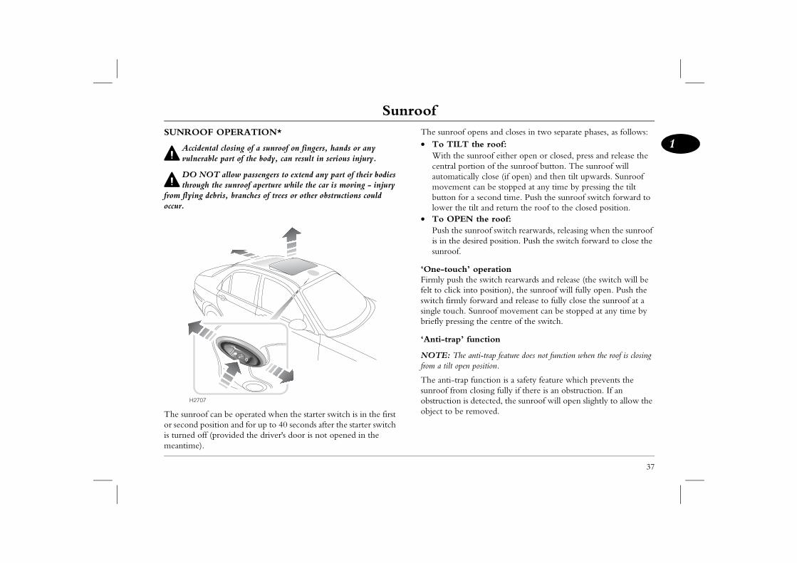
SUNROOF OPERATION*
Accidental closing of a sunroof on fingers, hands or any vulnerable part of the body, can result in serious injury.
DO NOT allow passengers to extend any part of their bodies through the sunroof aperture while the car is moving - injury
from flying debris, branches of trees or other obstructions could occur.
The sunroof can be operated when the starter switch is in the first or second position and for up to 40 seconds after the starter switch is turned off (provided the driver's door is not opened in the meantime).
The sunroo• To TIL
With thecentral pautomatimovemebutton folower th
• To OPEPush theis in the sunroof.
‘One-toucFirmly pushfelt to click switch firmlsingle touchbriefly press
‘Anti-trap’
NOTE: Thfrom a tilt op
The anti-trasunroof fromobstruction object to be
H2707
Heating & VentilationHeating & VentilationVENTILATION Cars fitted with Automatic Temperature Control (ATC) are
equipped with an additional outlet which supplies unheated or cooled air to the rear of the passenger compartment.
wheel down to close or up to open the vents. by moving the control in the centre of the n, or from side to side.
r seat passengers, direct air from the outer vents seat occupants and use the centre vents to direct r seat passengers.
e output from the centre face vents, shut the outer
38
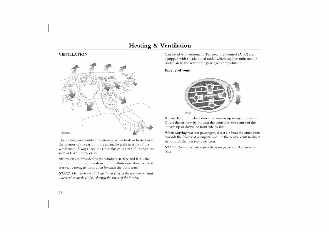
The heating and ventilation system provides fresh or heated air to the interior of the car from the air intake grille in front of the windscreen. Always keep the air intake grille clear of obstructions such as leaves, snow or ice.
Air outlets are provided to the windscreen, face and feet - the location of those vents is shown in the illustration above - and to rear seat passengers from ducts beneath the front seats.
NOTE: On saloon models, keep the air grille in the rear window shelf uncovered to enable air flow through the whole of the interior.
Face level vents
Rotate the thumbDirect the air flowlouvres up or dow
When carrying reatowards the front air towards the rea
NOTE: To increasvents.
H2833b
H2733
Heating & Ventilation
39
1stribution control
: When distributing air to the face level vents, they must be open to ensure best performance.
ace level vents only.
oot and face level vents.
oot level vents.
oot level, windscreen and side window vents.
indscreen and side window vents.
r switche switch clockwise to increase the blower speed.
: With the blower switched off, the volume of air entering the pendent on driving speed alone.ulated air supply button operate (the indicator light in the switch illuminates).
his button pressed, the heater recirculates the air inside the car, preventing the entry of traffic fumes.ain to switch off.ir conditioning is switched on, air recirculation will active until fresh air is selected, or until the air oning is switched off.ir conditioning switched off (and on cars not equipped r conditioning), air recirculation will automatically off after 4 minutes operation. This reduces the risk of windows. To override this timed feature, press and
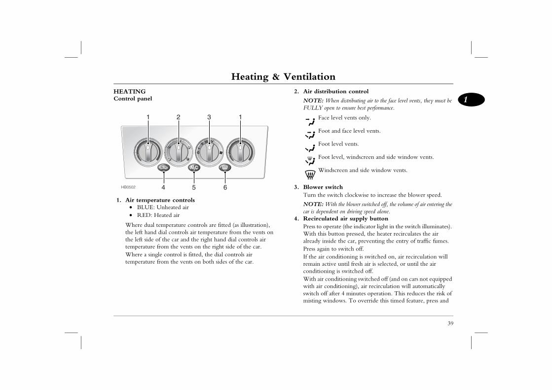
HEATINGControl panel
1. Air temperature controls• BLUE: Unheated air• RED: Heated air
Where dual temperature controls are fitted (as illustration), the left hand dial controls air temperature from the vents on the left side of the car and the right hand dial controls air temperature from the vents on the right side of the car.Where a single control is fitted, the dial controls air temperature from the vents on both sides of the car.
2. Air di
NOTEFULLY
F
F
F
F
W
3. BloweTurn th
NOTEcar is de
4. RecircPress toWith talreadyPress agIf the aremainconditiWith awith aiswitch misting
HB0502
1 12 3
4 5 6
Heating & Ventilationhold the recirculation button for 2 seconds (until the light in the switch flashes) - but note that the function must then be switched off manually.
6. Rear screen demisterThe demister will only function with the engine running.
ate; the indicator light in the switch illuminates demister is on and extinguishes when the rned off.r temperature is below 10° C (50° F), the switch on automatically and operate for a period s before switching off. However, if the exterior is greater than 10° C (50° F), the demister will automatically, but will respond to any manual switching off automatically after 12 minutes.
lements on the inside of the rear screen are easily NOT scrape or scratch the glass. DO NOT
e heating elements.
40
NOTE: Leaving the system in recirculation mode can cause the windscreen to mist. If this happens, switch off recirculation and turn the controls to maximum demisting.
5. Air conditioning switch*With the engine running, press to operate. The indicator light in the switch illuminates when the air conditioning is switched on. In addition, note that air recirculation is activated automatically whenever the air conditioning is switched on as an aid to more efficient cooling of the car's interior. In conditions of high humidity, slight screen misting may be experienced when the air conditioning is first switched on. This is not a fault, misting will clear after a few seconds once the system is in operation.
NOTE: The air conditioning will not operate without the engine running nor when the blower switch is turned to position 'O'.
NOTE: Because the system dehumidifies the air supplied to it, surplus water is produced and expelled via drain tubes beneath the car. This may result in a small pool of water forming under the car when stationary and is not a cause for concern.
Press to operwhenever thedemister is tuIf the exteriodemister will of 20 minutetemperature not switch onoperation by
The heating edamaged. DO
stick labels over th
Heating & Ventilation
41
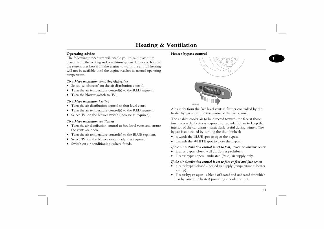
1ass control
rom the face level vents is further controlled by the ss control in the centre of the fascia panel.
cooler air to be directed towards the face at those the heater is required to provide hot air to keep the he car warm - particularly useful during winter. The ntrolled by turning the thumbwheel:the BLUE spot to open the bypass.the WHITE spot to close the bypass.
tribution control is set to foot, screen or window vents:ypass closed - all air flow is prohibited.ypass open - unheated (fresh) air supply only.
tribution control is set to face or foot and face vents:ypass closed - heated air supply (temperature as heater
ypass open - a blend of heated and unheated air (which ssed the heater) providing a cooler output.
H2861
Operating adviceThe following procedures will enable you to gain maximum benefit from the heating and ventilation system. However, because the system uses heat from the engine to warm the air, full heating will not be available until the engine reaches its normal operating temperature.
To achieve maximum demisting/defrosting• Select ‘windscreen’ on the air distribution control.• Turn the air temperature control(s) to the RED segment.• Turn the blower switch to ‘IV’.
To achieve maximum heating• Turn the air distribution control to foot level vents. • Turn the air temperature control(s) to the RED segment. • Select ‘IV’ on the blower switch (increase as required).
To achieve maximum ventilation• Turn the air distribution control to face level vents and ensure
the vents are open.• Turn the air temperature control(s) to the BLUE segment. • Select ‘IV’ on the blower switch (adjust as required).• Switch on air conditioning (where fitted).
Heater byp
Air supply fheater bypa
The enablestimes wheninterior of tbypass is co• towards • towards
If the air dis• Heater b• Heater b
If the air dis• Heater b
setting).• Heater b
has bypa
Heating & VentilationParticle/pollen filter/odour filter*A particle filter will help to keep the car interior free from pollen and dust. To remain fully effective, the filter should be replaced
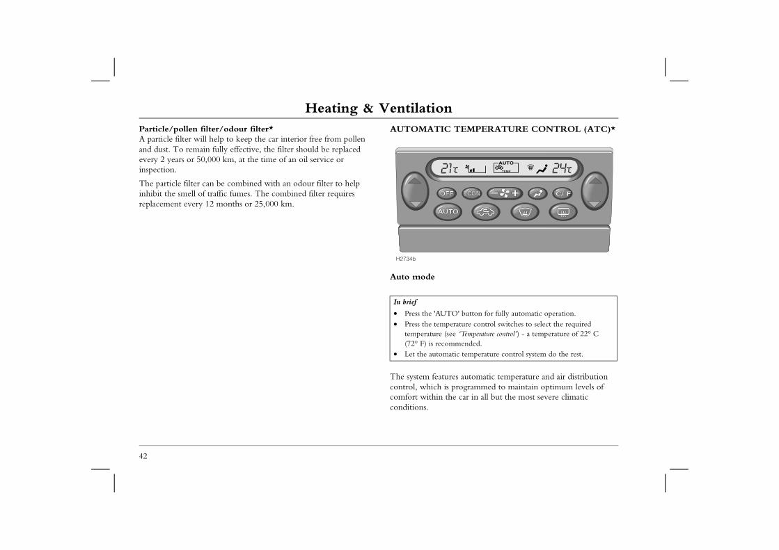
AUTOMATIC TEMPERATURE CONTROL (ATC)*
es automatic temperature and air distribution programmed to maintain optimum levels of e car in all but the most severe climatic
O' button for fully automatic operation.rature control switches to select the required e ‘Temperature control’) - a temperature of 22° C mended.
tic temperature control system do the rest.
TEMP
42
every 2 years or 50,000 km, at the time of an oil service or inspection.
The particle filter can be combined with an odour filter to help inhibit the smell of traffic fumes. The combined filter requires replacement every 12 months or 25,000 km.
Auto mode
The system featurcontrol, which is comfort within thconditions.
In brief
• Press the 'AUT• Press the tempe
temperature (se(72° F) is recom
• Let the automa
H2734b
Heating & Ventilation
43
1re control
rocker switches on either side of the display to set the perature for the corresponding side of the passenger t (left hand switch for the left side of the car, and right for the right side). The system will not achieve s on the passenger side of the car more than 5° C ss than the temperature set for the driver's side.
es above 28° C and below 16° C cannot be set. Above ese maximum and minimum settings ‘HI’ or ‘LO’ will e display.
e temperatures shown on the display are target temperatures not reflective of any specific temperature measured within the car.
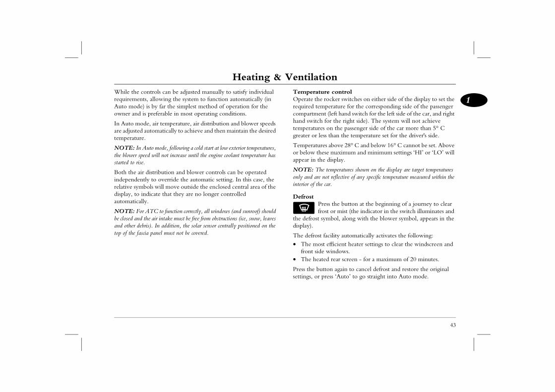
ress the button at the beginning of a journey to clear ost or mist (the indicator in the switch illuminates and ymbol, along with the blower symbol, appears in the
facility automatically activates the following:t efficient heater settings to clear the windscreen and e windows.ted rear screen - for a maximum of 20 minutes.
tton again to cancel defrost and restore the original press ‘Auto’ to go straight into Auto mode.
While the controls can be adjusted manually to satisfy individual requirements, allowing the system to function automatically (in Auto mode) is by far the simplest method of operation for the owner and is preferable in most operating conditions.
In Auto mode, air temperature, air distribution and blower speeds are adjusted automatically to achieve and then maintain the desired temperature.
NOTE: In Auto mode, following a cold start at low exterior temperatures, the blower speed will not increase until the engine coolant temperature has started to rise.
Both the air distribution and blower controls can be operated independently to override the automatic setting. In this case, the relative symbols will move outside the enclosed central area of the display, to indicate that they are no longer controlled automatically.
NOTE: For ATC to function correctly, all windows (and sunroof) should be closed and the air intake must be free from obstructions (ice, snow, leaves and other debris). In addition, the solar sensor centrally positioned on the top of the fascia panel must not be covered.
TemperatuOperate therequired temcompartmenhand switchtemperaturegreater or le
Temperaturor below thappear in th
NOTE: Thonly and are interior of the
DefrostPfr
the defrost sdisplay).
The defrost• The mos
front sid• The hea
Press the busettings, or
Heating & VentilationEconomy mode
Press the ‘ECON’ button to operate (the display shows ‘ECON’).
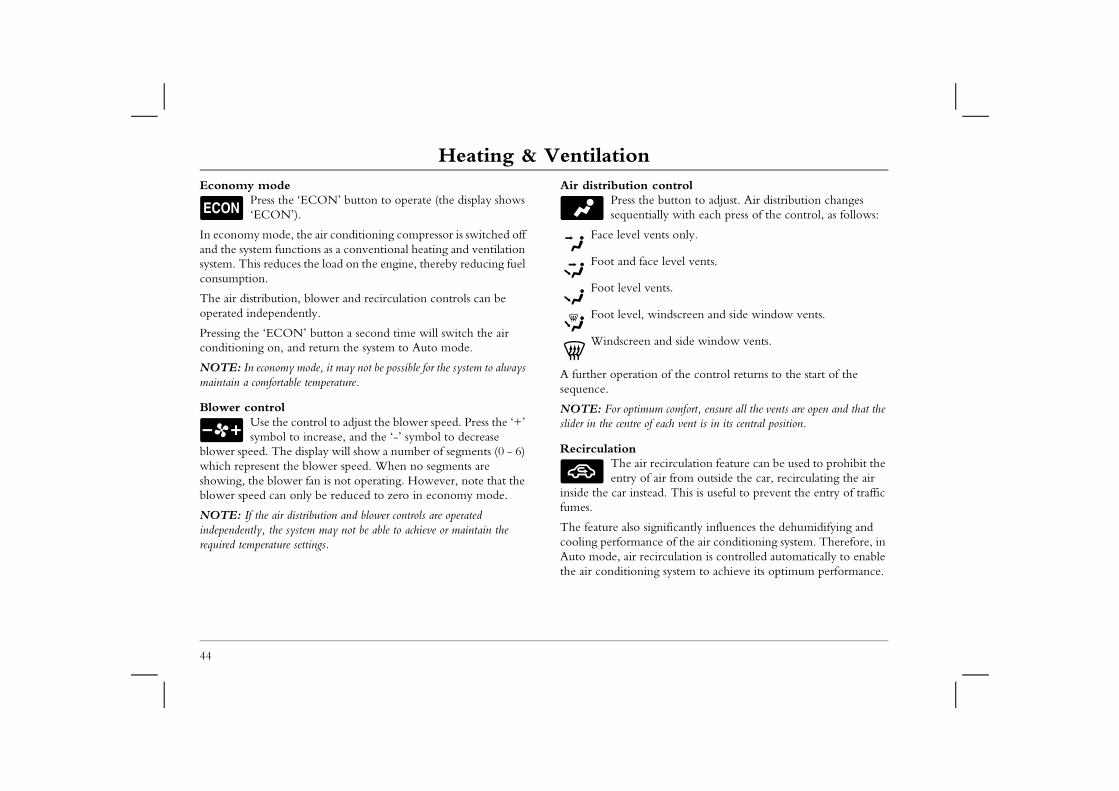
Air distribution controlPress the button to adjust. Air distribution changes sequentially with each press of the control, as follows:
ents only.
e level vents.
ents.
indscreen and side window vents.
and side window vents.
n of the control returns to the start of the
um comfort, ensure all the vents are open and that the f each vent is in its central position.
recirculation feature can be used to prohibit the air from outside the car, recirculating the air ad. This is useful to prevent the entry of traffic
gnificantly influences the dehumidifying and ce of the air conditioning system. Therefore, in circulation is controlled automatically to enable g system to achieve its optimum performance.
44
In economy mode, the air conditioning compressor is switched off and the system functions as a conventional heating and ventilation system. This reduces the load on the engine, thereby reducing fuel consumption.
The air distribution, blower and recirculation controls can be operated independently.
Pressing the ‘ECON’ button a second time will switch the air conditioning on, and return the system to Auto mode.
NOTE: In economy mode, it may not be possible for the system to always maintain a comfortable temperature.
Blower controlUse the control to adjust the blower speed. Press the ‘+’ symbol to increase, and the ‘-’ symbol to decrease
blower speed. The display will show a number of segments (0 - 6) which represent the blower speed. When no segments are showing, the blower fan is not operating. However, note that the blower speed can only be reduced to zero in economy mode.
NOTE: If the air distribution and blower controls are operated independently, the system may not be able to achieve or maintain the required temperature settings.
Face level v
Foot and fac
Foot level v
Foot level, w
Windscreen
A further operatiosequence.
NOTE: For optimslider in the centre o
RecirculationThe air entry of
inside the car instefumes.
The feature also sicooling performanAuto mode, air rethe air conditionin
Heating & Ventilation
45
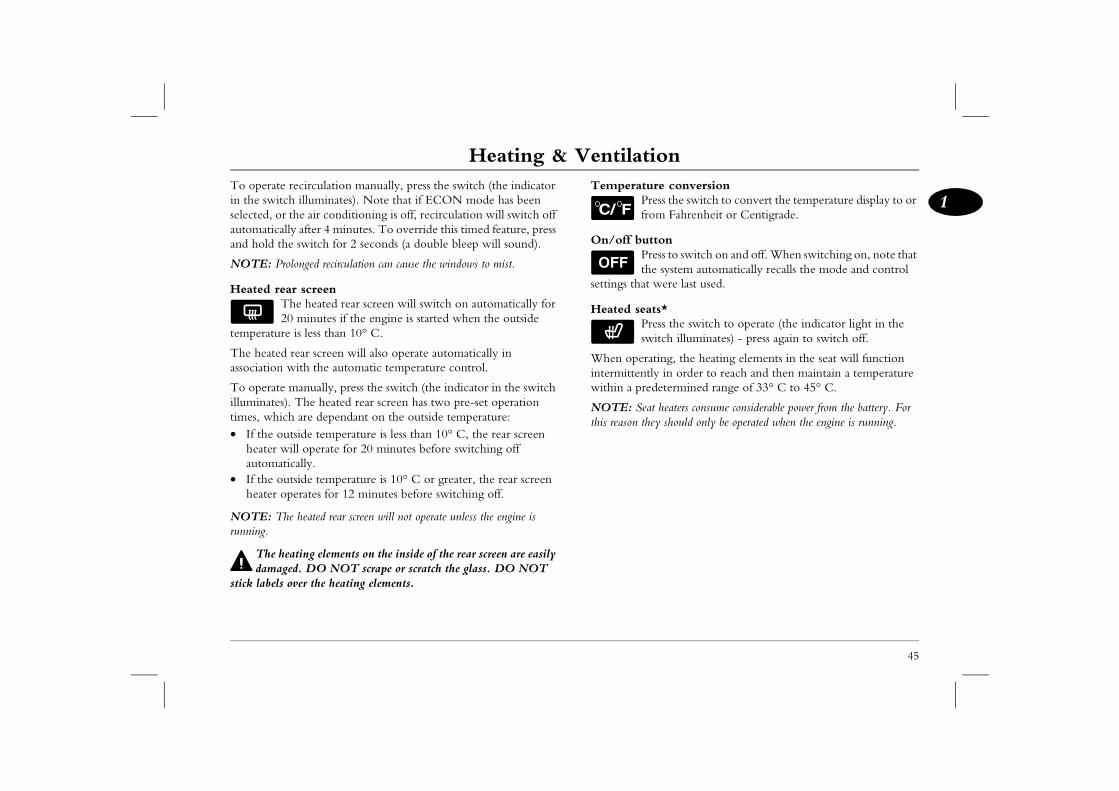
1re conversion
ress the switch to convert the temperature display to or om Fahrenheit or Centigrade.
ttonress to switch on and off. When switching on, note that e system automatically recalls the mode and control were last used.
ts*ress the switch to operate (the indicator light in the itch illuminates) - press again to switch off.
ating, the heating elements in the seat will function ly in order to reach and then maintain a temperature determined range of 33° C to 45° C.
t heaters consume considerable power from the battery. For ey should only be operated when the engine is running.
To operate recirculation manually, press the switch (the indicator in the switch illuminates). Note that if ECON mode has been selected, or the air conditioning is off, recirculation will switch off automatically after 4 minutes. To override this timed feature, press and hold the switch for 2 seconds (a double bleep will sound).
NOTE: Prolonged recirculation can cause the windows to mist.
Heated rear screenThe heated rear screen will switch on automatically for 20 minutes if the engine is started when the outside
temperature is less than 10° C.
The heated rear screen will also operate automatically in association with the automatic temperature control.
To operate manually, press the switch (the indicator in the switch illuminates). The heated rear screen has two pre-set operation times, which are dependant on the outside temperature: • If the outside temperature is less than 10° C, the rear screen
heater will operate for 20 minutes before switching off automatically.
• If the outside temperature is 10° C or greater, the rear screen heater operates for 12 minutes before switching off.
NOTE: The heated rear screen will not operate unless the engine is running.
The heating elements on the inside of the rear screen are easily damaged. DO NOT scrape or scratch the glass. DO NOT
stick labels over the heating elements.
TemperatuPfr
On/off buPth
settings that
Heated seaPsw
When operintermittentwithin a pre
NOTE: Seathis reason th
Parking HeaterParking HeaterPARKING HEATER*Some diesel engine cars are equipped with a programmable automatic heating facility, which enables the owner to pre-heat
DO NOT operate the parking heater in enclosed spaces, such as garages or workshops. A hazardous build up of exhaust
fumes may occur.
perate the parking heater where there is a risk of ch as filling stations where flammable liquids or nt, for example).
CAR’S HEATER CONTROLSr utilises the car’s interior heating and ventilation s therefore recommended that the car is left with er settings selected if the parking heater is to be utomatic operation. These settings have been the optimum comfort with acceptable battery used for a duration of 30 minutes. These
mended, but can be adjusted for individual
ual temperature controls to 22° C.O’ button to activate Auto mode.
46
the interior of the car (and warm up the engine) prior to use. The parking heater can also be operated remotely, using the handset supplied.
In addition to warming the vehicle interior and engine, the parking heater facility also reduces engine start-up emissions.
To warm the interior of the car, the parking heater economically burns a small amount of fuel drawn from the main fuel tank to generate heat, which is then distributed to the engine and the car's heating system.
The parking heater will then operate until the preset running time has elapsed, heating and maintaining the car's interior at the desired temperature. The heating programme can be cancelled at any time by pressing the ‘OFF’ button on the remote handset.
Avoid repeated operation of the parking heater, as this can discharge the car battery - it will take the car's charging system approximately 20 minutes of normal driving to recover the charge expended during 30 minutes operation of the parking heater (sometimes longer in extremely cold conditions).
NOTE: The parking heater operates independently of the car's ignition system - there is no need to leave the starter key in the starter switch and do not leave the car with the starter switch turned on.
DO NOT ofire (areas su
gases may be prese
SETTING THEThe parking heatesystem settings, it ithe following heatprogrammed for afound to provide power usage whensettings are recomcomfort.• Set the individ• Press the ‘AUT
Parking Heater
47
1t controls
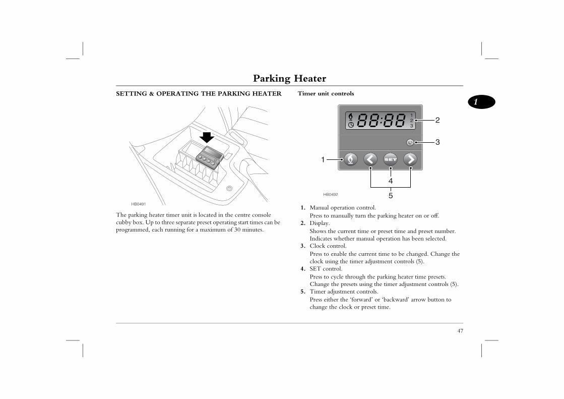
l operation control. manually turn the parking heater on or off..the current time or preset time and preset number. es whether manual operation has been selected.control. enable the current time to be changed. Change the sing the timer adjustment controls (5).ntrol. cycle through the parking heater time presets.
e the presets using the timer adjustment controls (5).adjustment controls.ither the ‘forward’ or ‘backward’ arrow button to the clock or preset time.
SET
0492
123
3
4
5
2
SETTING & OPERATING THE PARKING HEATER
The parking heater timer unit is located in the centre console cubby box. Up to three separate preset operating start times can be programmed, each running for a maximum of 30 minutes.
Timer uni
1. ManuaPress to
2. DisplayShows Indicat
3. Clock Press toclock u
4. SET coPress toChang
5. Timer Press echange
SET
HB0491
HB
1
Parking HeaterSetting the current time
NOTE: Both the current time and any preset start-up time are set and
Setting the heater start time presetsUp to three different preset start times can be programmed using the timer unit, as follows:
’ control (4) in the timer unit - the display wing a preset programme number (on the right
e display) and previously programmed start time that preset.reset is not displayed, press and release the ‘SET’ his cycles through the presets - repeat until the umber is displayed.art time for that preset, use the timer adjustment set the desired time.
begin to set the start time within approximately 10 he desired preset (before the display illumination e above procedure must be repeated.
wish to cancel the programming process, press T’ control repeatedly (cycling through the
ntil the display and preset number extinguish.
et programmehe ‘SET’ control (4) repeatedly until the desired isplayed (‘1’, ‘2’ or ‘3’) and check that the start
ter 10 seconds, the start time will extinguish, but s illuminated. The timer is now set to activate rogrammed time.
mmed preset start-up time, press and release the eatedly (cycling through the preset numbers) xtinguishes.
48
displayed in 24 hour clock format.
If the power supply to the unit has been interrupted (by vehicle battery disconnection, for example), the time of day will need to be reset and any preset programmes will be lost. Reset the time as follows:• Press the clock control (3) - the display illuminates and the
clock symbol and ‘:’ flash.• Set the time using the timer adjustment controls (5), pressing
the right control to advance the time and the left control to turn the clock back. The time increments in minutes, with the incremental change accelerating the longer the control is kept depressed.
• Once the correct time is displayed, release the control and leave the unit for approximately 10 seconds, until the display extinguishes.
NOTE: To display the current time, press the clock control. The display illumination ceases 10 seconds after the control is released.
• Press the ‘SETilluminates, shohand side of thassociated with
• If the desired pcontrol again. Tdesired preset n
• To adjust the stcontrols (5) to
NOTE: You mustseconds of selecting tceases), otherwise th
If at any time youand release the ‘SEpreset numbers) u
Selecting a presPress and release tpreset number is dtime is correct. Afthe display remainthe heater at the p
To cancel a progra‘SET’ control repuntil the display e
Parking Heater
49
1HE REMOTE HANDSET
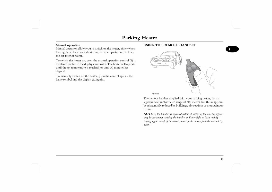
handset supplied with your parking heater, has an unobstructed range of 300 metres, but this range can
ally reduced by buildings, obstructions or mountainous
he handset is operated within 2 metres of the car, the signal rong, causing the handset indicator light to flash rapidly error). If this occurs, move further away from the car and try
8
Manual operationManual operation allows you to switch on the heater, either when leaving the vehicle for a short time, or when parked up, to keep the car interior warm.
To switch the heater on, press the manual operation control (1) - the flame symbol in the display illuminates. The heater will operate until the set temperature is reached, or until 30 minutes has elapsed.
To manually switch off the heater, press the control again - the flame symbol and the display extinguish.
USING T
The remoteapproximatebe substantiterrain.
NOTE: If tmay be too st(signifying anagain.
HB048
Parking HeaterRemote handset controls To deactivate the parking heater at any time during operation,
press and hold the ‘OFF’ button for approximately 1 second (or until the indicator light illuminates constantly). The indicator light
lashing.
eset running timeg time can be adjusted, in 10 minute increments, es and 60 minutes. To check the duration of the ed running time, press and release both the uttons simultaneously three times in quick
umber of times the indicator light flashes time (in minutes x 10) that the parking heater .g. a single flash = 10 minutes, 4 flashes = 40
to alter the running time, leave the handset for hich it will return to operating mode.
1
50
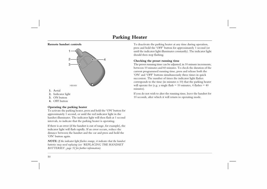
1. Aerial2. Indicator light3. ON button4. OFF button
Operating the parking heaterTo activate the parking heater, press and hold the ‘ON’ button for approximately 1 second, or until the red indicator light in the handset illuminates. The indicator light will then flash at 1 second intervals, to indicate that the parking heater is operating.
If there is an error (if the handset is out of range, for example), the indicator light will flash rapidly. If an error occurs, reduce the distance between the handset and the car and press and hold the ‘ON’ button again.
NOTE: If the indicator light flashes orange, it indicates that the handset batteries may need replacing (see ‘REPLACING THE HANDSET BATTERIES’, page 52 for further information).
should then stop f
Checking the prThe preset runninbetween 10 minutcurrent programm‘ON’ and ‘OFF’ bsuccession. The ncorresponds to thewill operate for (eminutes).
If you do not wish10 seconds, after w
HB0489
3
2 4
Parking Heater
51
1 OF CAR BATTERY DISCONNECTIONttery is disconnected or discharged for a short time, the l unit's programmed time settings and presets will be trol unit display flashes). The time and preset settings be re-entered before the system will operate ly (see ‘SETTING & OPERATING THE PARKING page 47).
ttery is disconnected or discharged for a prolonged e, the remote handset may lose synchronisation with
unit. Although this is unlikely, the handset can be sed by following the procedure detailed below.
ONISING THE HANDSET/MMING ADDITIONAL HANDSETSe handset has lost synchronisation with the parking ver (if the car battery has been disconnected for a eriod, for example), or if an additional handset is to be d, the handset will need to be synchronised. the negative lead on the car battery for a minimum of econnect the negative lead and, within 2 seconds, ld the handset ‘OFF’ button for a further 2 seconds ely). The handset indicator light will flash once to t the handset is now synchronised correctly. If the light , repeat the above procedure.
to 2 additional remote handsets can be synchronised for use rking heater. Replacement or additional handsets can be gh your MG Rover dealer.
Changing the preset running timePress and release both the ‘ON’ and ‘OFF’ buttons simultaneously three times in quick succession. The indicator light flashes as described above. Within 10 seconds, press the ‘OFF’ button, to increase the running time by 10 minutes - the indicator light will flash the correct number of times to confirm the new running time (one flash for 10 minutes, two flashes for twenty minutes et.c.). Continue to press and release the ‘OFF’ button until the desired running time is reached. To set the new running time, either briefly press the ‘ON’ button, or do not press any button for 10 seconds - the new running time is now set.
To return the running time to its default value (30 minutes), press and hold both the ‘ON’ and ‘OFF’ buttons simultaneously for 10 seconds, at which point the indicator light will extinguish.
EFFECTSIf the car batimer controlost (the conwill need toautomaticalHEATER’,
If the car baperiod of timthe control resynchroni
SYNCHRPROGRAIf the remotheater receiprolonged pprogrammeDisconnect 5 seconds. Rpress and ho(approximatconfirm thafails to flash
NOTE: Upwith your paordered throu
IMPORTANT
To avoid inadvertent drain on the car battery, it is not recommended that the preset running time be increased from the default (30 minutes), except in extreme conditions.
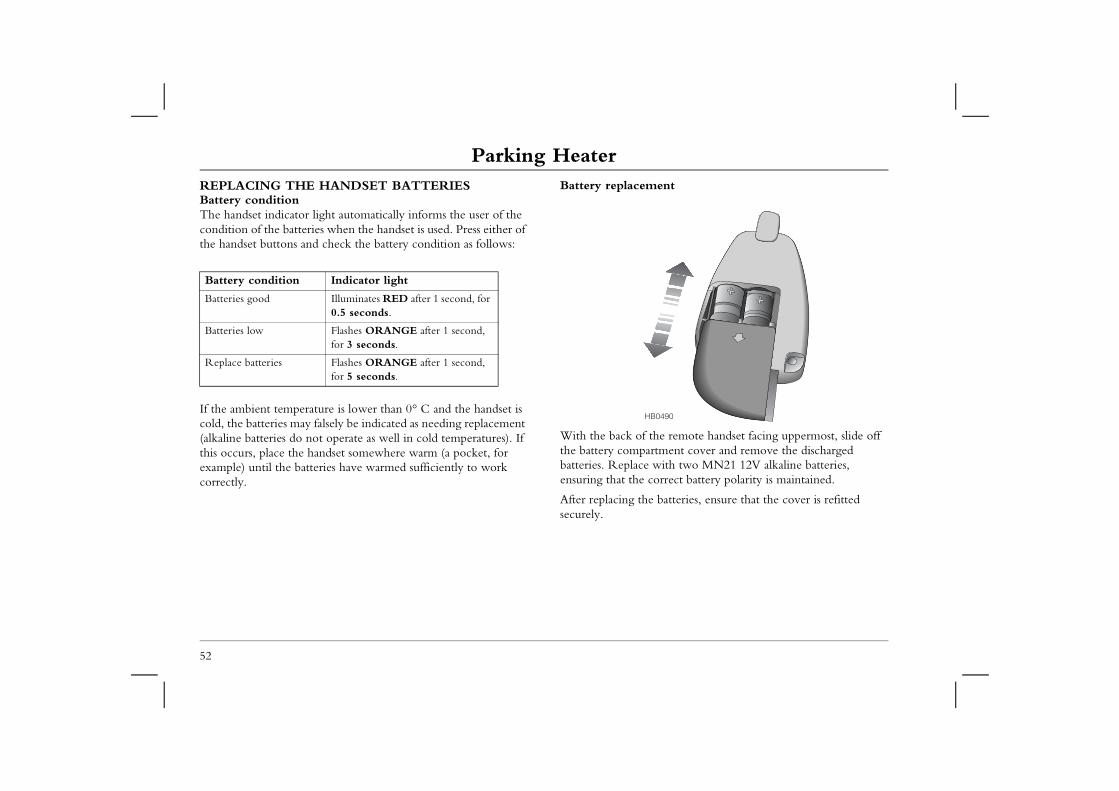
Parking HeaterREPLACING THE HANDSET BATTERIESBattery conditionThe handset indicator light automatically informs the user of the
Battery replacement
the remote handset facing uppermost, slide off rtment cover and remove the discharged with two MN21 12V alkaline batteries, correct battery polarity is maintained.
e batteries, ensure that the cover is refitted
B0490
52
condition of the batteries when the handset is used. Press either of the handset buttons and check the battery condition as follows:
If the ambient temperature is lower than 0° C and the handset is cold, the batteries may falsely be indicated as needing replacement (alkaline batteries do not operate as well in cold temperatures). If this occurs, place the handset somewhere warm (a pocket, for example) until the batteries have warmed sufficiently to work correctly.
With the back of the battery compabatteries. Replaceensuring that the
After replacing thsecurely.
Battery condition Indicator light
Batteries good Illuminates RED after 1 second, for 0.5 seconds.
Batteries low Flashes ORANGE after 1 second, for 3 seconds.
Replace batteries Flashes ORANGE after 1 second, for 5 seconds.
H
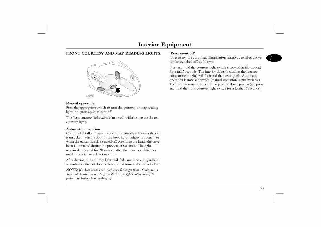
Interior Equipment
53
1Interior Equipment t off’
the automatic illumination features described above hed off, as follows:
ld the courtesy light switch (arrowed in illustration) econds. The interior lights (including the luggage t light) will flash and then extinguish. Automatic
now suppressed (manual operation is still available). utomatic operation, repeat the above process (i.e. press e front courtesy light switch for a further 5 seconds).
FRONT COURTESY AND MAP READING LIGHTS
Manual operationPress the appropriate switch to turn the courtesy or map reading lights on, press again to turn off.
The front courtesy light switch (arrowed) will also operate the rear courtesy lights.
Automatic operationCourtesy light illumination occurs automatically whenever the car is unlocked, when a door or the boot lid or tailgate is opened, or when the starter switch is turned off, providing the headlights have been illuminated during the previous 30 seconds. The lights remain illuminated for 20 seconds after the doors are closed, or until the starter switch is turned on.
After driving, the courtesy lights will fade and then extinguish 20 seconds after the last door is closed, or as soon as the car is locked.
NOTE: If a door or the boot is left open for longer than 16 minutes, a ‘time-out’ function will extinguish the interior lights automatically to prevent the battery from discharging.
‘PermanenIf necessary,can be switc
Press and hofor a full 5 scompartmenoperation isTo restore aand hold th
H2675a
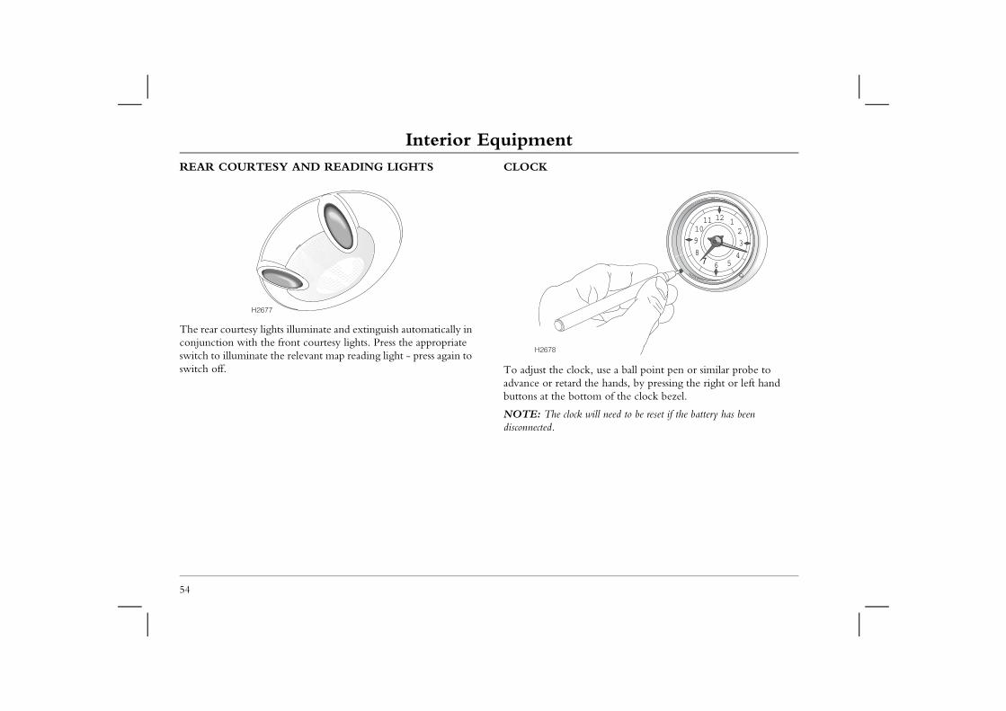
Interior EquipmentREAR COURTESY AND READING LIGHTS CLOCK
k, use a ball point pen or similar probe to the hands, by pressing the right or left hand tom of the clock bezel.
will need to be reset if the battery has been
123
456
891011 12
54
The rear courtesy lights illuminate and extinguish automatically in conjunction with the front courtesy lights. Press the appropriate switch to illuminate the relevant map reading light - press again to switch off. To adjust the cloc
advance or retard buttons at the bot
NOTE: The clock disconnected.
H2677
H2678
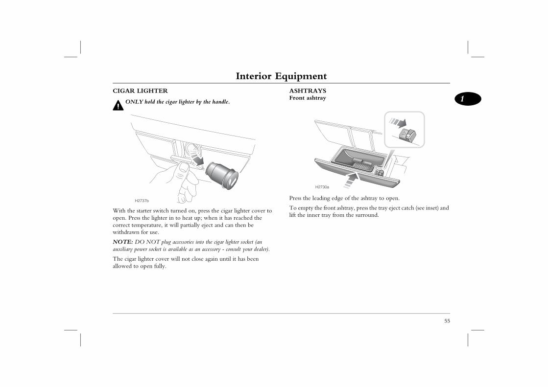
Interior Equipment
55
1YSray
ding edge of the ashtray to open.
e front ashtray, press the tray eject catch (see inset) and r tray from the surround.
2730a
CIGAR LIGHTER
ONLY hold the cigar lighter by the handle.
With the starter switch turned on, press the cigar lighter cover to open. Press the lighter in to heat up; when it has reached the correct temperature, it will partially eject and can then be withdrawn for use.
NOTE: DO NOT plug accessories into the cigar lighter socket (an auxiliary power socket is available as an accessory - consult your dealer).
The cigar lighter cover will not close again until it has been allowed to open fully.
ASHTRAFront asht
Press the lea
To empty thlift the inne
H2737b
H
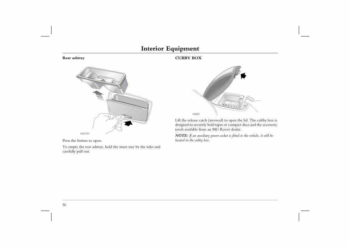
Interior EquipmentRear ashtray CUBBY BOX
ch (arrowed) to open the lid. The cubby box is ly hold tapes or compact discs and the accessory m an MG Rover dealer.
liary power socket is fitted to the vehicle, it will be box.
56
Press the button to open.
To empty the rear ashtray, hold the inner tray by the sides and carefully pull out.
Lift the release catdesigned to securetorch available fro
NOTE: If an auxilocated in the cubby
H2721
H2697
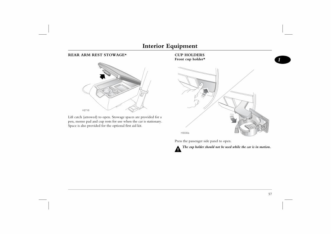
Interior Equipment
57
1DERSholder*
ssenger side panel to open.
p holder should not be used while the car is in motion.
REAR ARM REST STOWAGE*
Lift catch (arrowed) to open. Stowage spaces are provided for a pen, memo pad and cup rests for use when the car is stationary. Space is also provided for the optional first aid kit.
CUP HOLFront cup
Press the pa
The cu
H2718
H3030a
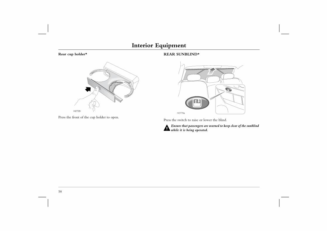
Interior EquipmentRear cup holder* REAR SUNBLIND*
raise or lower the blind.
assengers are warned to keep clear of the sunblind ing operated.
58
Press the front of the cup holder to open.Press the switch to
Ensure that pwhile it is be
H2729H2779a
In-Car Telephones
59
1In-Car Telephones
IN-CAR TELEPHONESRefrain from operating a telephone fitted with its own aerial inside the car (see main text).
Your car uses a number of electronic systems designed to provide you with maximum comfort, safety and economy. These systems may be affected by the use of non-approved mobile communication equipment inside the car. However, the use of an external aerial will greatly reduce the likelihood of this occurrence.
Using any hand-held appliance while driving can be dangerous. Always stop the car before making or receiving a
call and ensure the telephone is switched off while you are driving.
For your safety, always note the following precautions before fitting or using an in-car telephone, or any electrical equipment:• Only use an installation kit incorporating an aerial external to
the vehicle.• Ensure that the installation is carried out by a competent
installer.• Refrain from operating a mobile phone fitted with its own
aerial inside the car - the electromagnetic field radiated by the phone may interfere with the car's electrical systems.
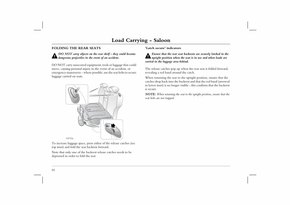
Load Carrying - SaloonLoad Carrying - SaloonFOLDING THE REAR SEATS
DO NOT carry objects on the rear shelf - they could become
‘Latch secure’ indicators
Ensure that the rear seat backrests are securely latched in the ion when the seat is in use and when loads are age area behind.
s pop up when the rear seat is folded forward, nd around the catch.
he seat to the upright position, ensure that the into the backrest and that the red band (arrowed o longer visible - this confirms that the backrest
rning the seat to the upright position, ensure that the pped.
60
dangerous projectiles in the event of an accident.
DO NOT carry unsecured equipment, tools or luggage that could move, causing personal injury in the event of an accident, or emergency manoeuvre - where possible, use the seat belts to secure luggage carried on seats.
To increase luggage space, press either of the release catches (see top inset) and fold the seat backrest forward.
Note that only one of the backrest release catches needs to be depressed in order to fold the seat.
upright positcarried in the lugg
The release catcherevealing a red ba
When returning tcatches drop back in lower inset) is nis secure.
NOTE: When retuseat belts are not tra
H2742a
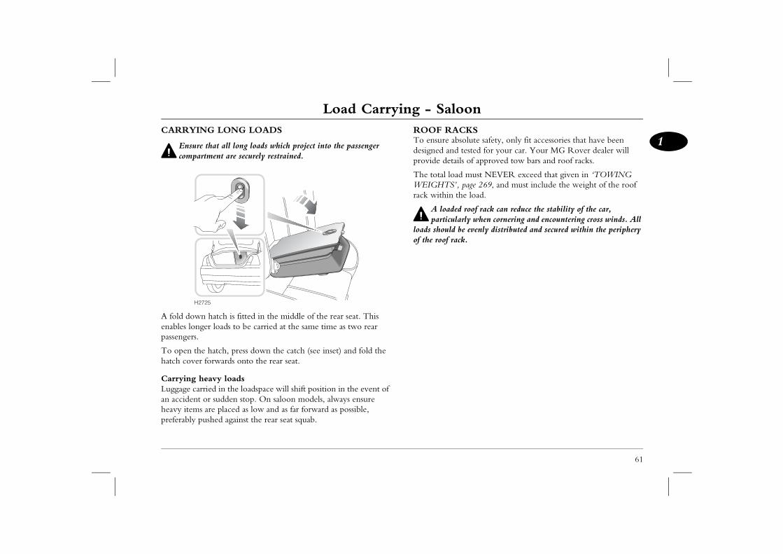
Load Carrying - Saloon
61
1CKS
bsolute safety, only fit accessories that have been d tested for your car. Your MG Rover dealer will ails of approved tow bars and roof racks.
ad must NEVER exceed that given in ‘TOWING ’, page 269, and must include the weight of the roof the load.
ed roof rack can reduce the stability of the car, larly when cornering and encountering cross winds. All be evenly distributed and secured within the periphery ack.
CARRYING LONG LOADS
Ensure that all long loads which project into the passenger compartment are securely restrained.
A fold down hatch is fitted in the middle of the rear seat. This enables longer loads to be carried at the same time as two rear passengers.
To open the hatch, press down the catch (see inset) and fold the hatch cover forwards onto the rear seat.
Carrying heavy loadsLuggage carried in the loadspace will shift position in the event of an accident or sudden stop. On saloon models, always ensure heavy items are placed as low and as far forward as possible, preferably pushed against the rear seat squab.
ROOF RATo ensure adesigned anprovide det
The total loWEIGHTSrack within
A loadparticu
loads shouldof the roof r
H2725
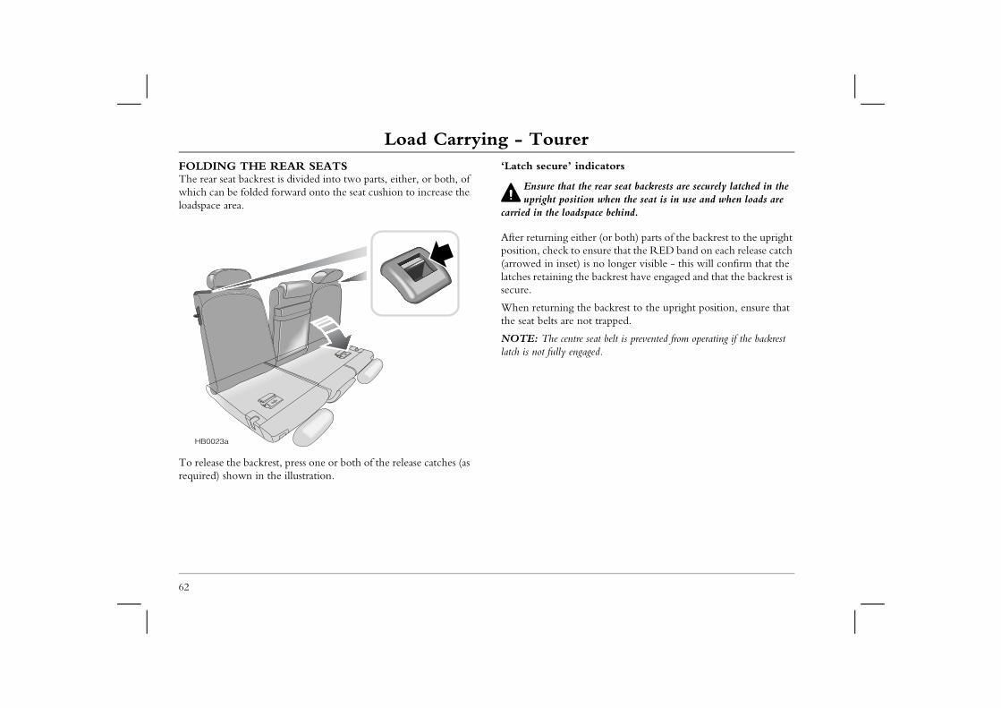
Load Carrying - TourerLoad Carrying - TourerFOLDING THE REAR SEATSThe rear seat backrest is divided into two parts, either, or both, of which can be folded forward onto the seat cushion to increase the
‘Latch secure’ indicators
Ensure that the rear seat backrests are securely latched in the ion when the seat is in use and when loads are space behind.
her (or both) parts of the backrest to the upright ensure that the RED band on each release catch is no longer visible - this will confirm that the e backrest have engaged and that the backrest is
he backrest to the upright position, ensure that ot trapped.
seat belt is prevented from operating if the backrest aged.
62
loadspace area.
To release the backrest, press one or both of the release catches (as required) shown in the illustration.
upright positcarried in the load
After returning eitposition, check to(arrowed in inset)latches retaining thsecure.
When returning tthe seat belts are n
NOTE: The centrelatch is not fully eng
HB0023a
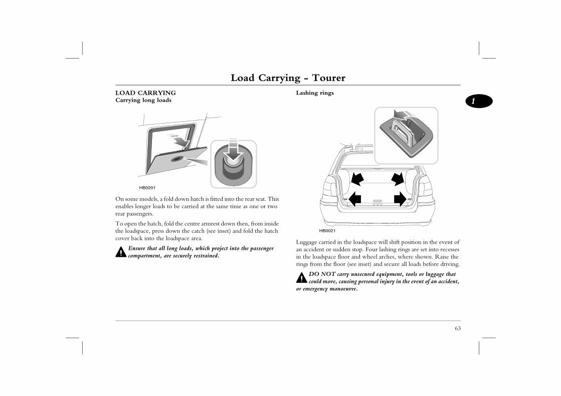
Load Carrying - Tourer
63
1gs
ried in the loadspace will shift position in the event of or sudden stop. Four lashing rings are set into recesses pace floor and wheel arches, where shown. Raise the he floor (see inset) and secure all loads before driving.
OT carry unsecured equipment, tools or luggage that ove, causing personal injury in the event of an accident,
y manoeuvre.
0021
LOAD CARRYINGCarrying long loads
On some models, a fold down hatch is fitted into the rear seat. This enables longer loads to be carried at the same time as one or two rear passengers.
To open the hatch, fold the centre armrest down then, from inside the loadspace, press down the catch (see inset) and fold the hatch cover back into the loadspace area.
Ensure that all long loads, which project into the passenger compartment, are securely restrained.
Lashing rin
Luggage caran accident in the loadsrings from t
DO Ncould m
or emergenc
HB0201
HB
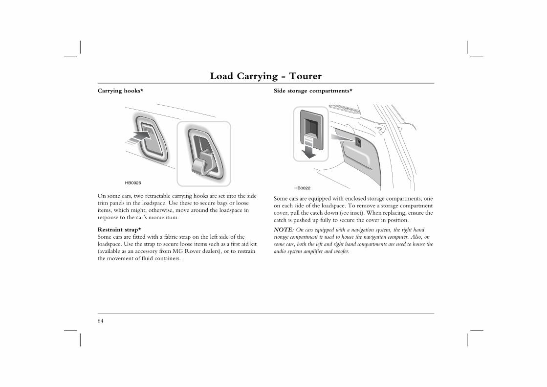
Load Carrying - TourerCarrying hooks* Side storage compartments*
ipped with enclosed storage compartments, one e loadspace. To remove a storage compartment ch down (see inset). When replacing, ensure the fully to secure the cover in position.
quipped with a navigation system, the right hand is used to house the navigation computer. Also, on eft and right hand compartments are used to house the ier and woofer.
64
On some cars, two retractable carrying hooks are set into the side trim panels in the loadspace. Use these to secure bags or loose items, which might, otherwise, move around the loadspace in response to the car’s momentum.
Restraint strap*Some cars are fitted with a fabric strap on the left side of the loadspace. Use the strap to secure loose items such as a first aid kit (available as an accessory from MG Rover dealers), or to restrain the movement of fluid containers.
Some cars are equon each side of thcover, pull the catcatch is pushed up
NOTE: On cars estorage compartmentsome cars, both the laudio system amplif
HB0026HB0022
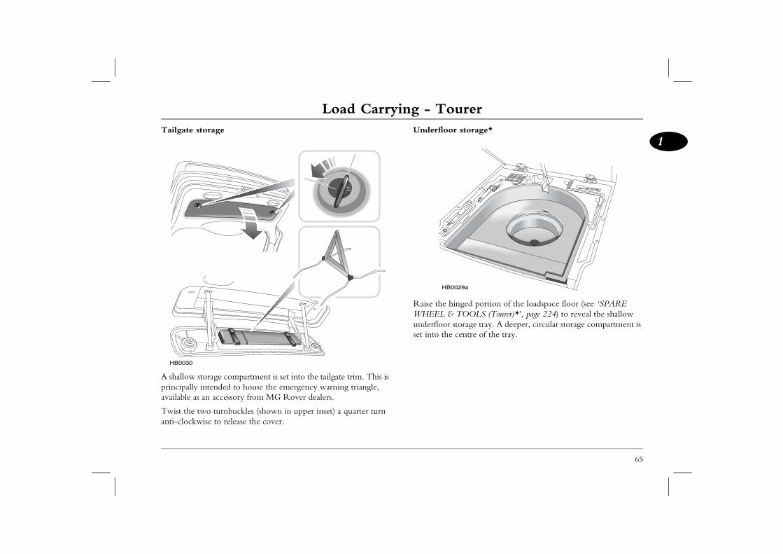
Load Carrying - Tourer
65
1r storage*
inged portion of the loadspace floor (see ‘SPARE TOOLS (Tourer)*’, page 224) to reveal the shallow torage tray. A deeper, circular storage compartment is centre of the tray.
029a
Tailgate storage
A shallow storage compartment is set into the tailgate trim. This is principally intended to house the emergency warning triangle, available as an accessory from MG Rover dealers.
Twist the two turnbuckles (shown in upper inset) a quarter turn anti-clockwise to release the cover.
Underfloo
Raise the hWHEEL &underfloor sset into the
HB0030
HB0
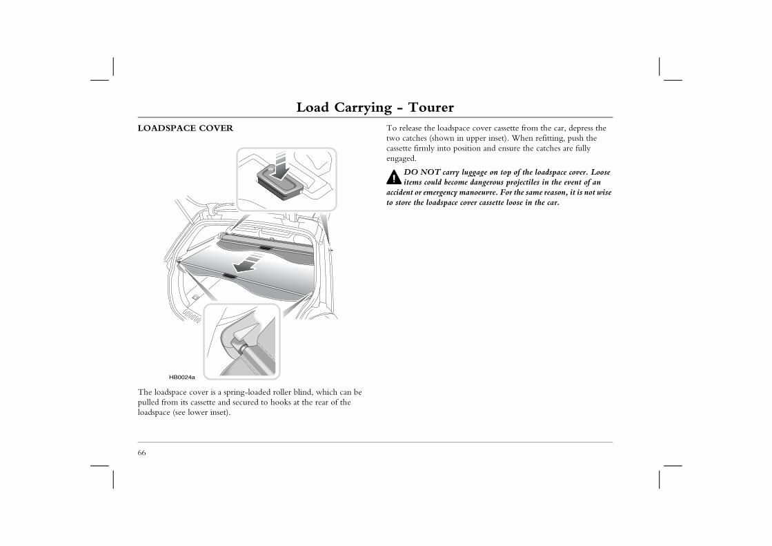
Load Carrying - TourerLOADSPACE COVER To release the loadspace cover cassette from the car, depress the
two catches (shown in upper inset). When refitting, push the cassette firmly into position and ensure the catches are fully
rry luggage on top of the loadspace cover. Loose ecome dangerous projectiles in the event of an cy manoeuvre. For the same reason, it is not wise
ace cover cassette loose in the car.
66
The loadspace cover is a spring-loaded roller blind, which can be pulled from its cassette and secured to hooks at the rear of the loadspace (see lower inset).
engaged.
DO NOT caitems could b
accident or emergento store the loadsp
HB0024a
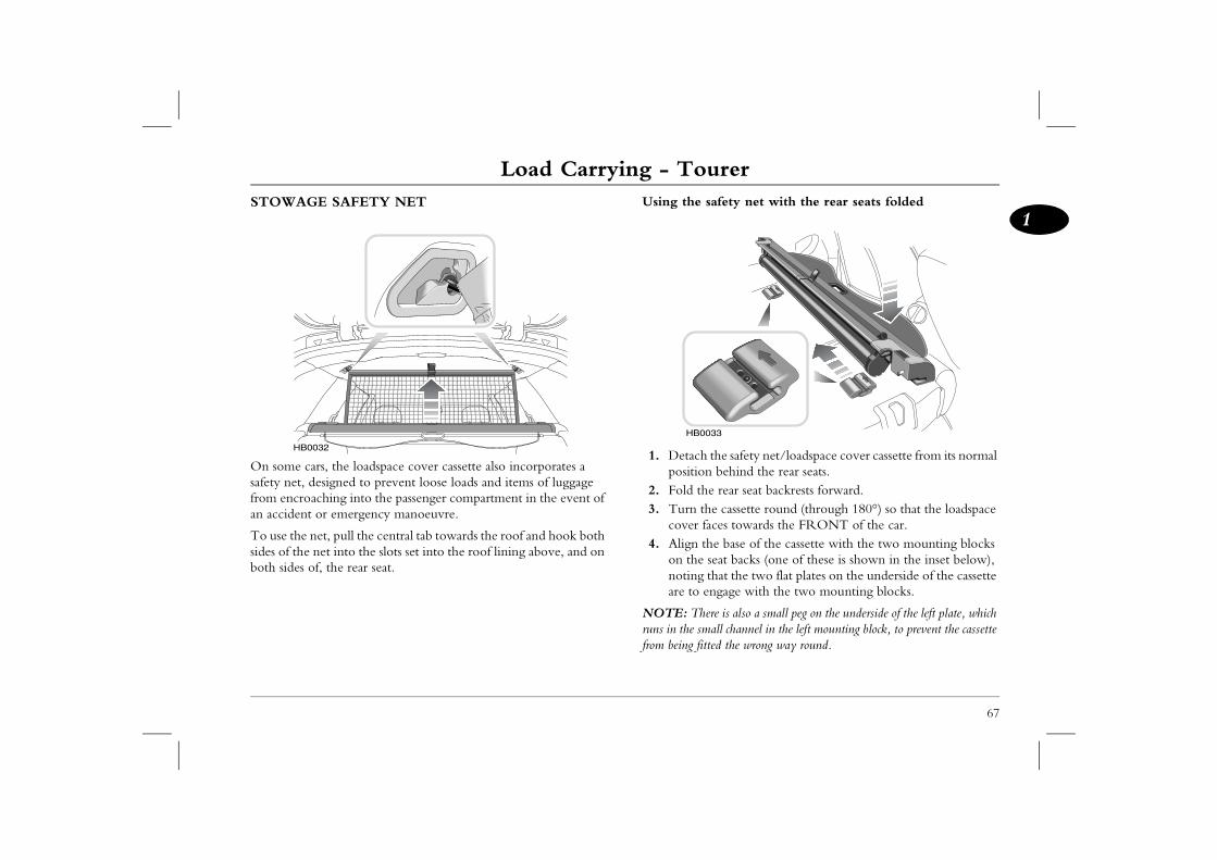
Load Carrying - Tourer
67
1safety net with the rear seats folded
the safety net/loadspace cover cassette from its normal n behind the rear seats.e rear seat backrests forward. e cassette round (through 180°) so that the loadspace
aces towards the FRONT of the car.he base of the cassette with the two mounting blocks seat backs (one of these is shown in the inset below), that the two flat plates on the underside of the cassette ngage with the two mounting blocks.
ere is also a small peg on the underside of the left plate, which all channel in the left mounting block, to prevent the cassette ted the wrong way round.
033
STOWAGE SAFETY NET
On some cars, the loadspace cover cassette also incorporates a safety net, designed to prevent loose loads and items of luggage from encroaching into the passenger compartment in the event of an accident or emergency manoeuvre.
To use the net, pull the central tab towards the roof and hook both sides of the net into the slots set into the roof lining above, and on both sides of, the rear seat.
Using the
1. Detachpositio
2. Fold th3. Turn th
cover f4. Align t
on the noting are to e
NOTE: Thruns in the smfrom being fit
HB0032
HB0
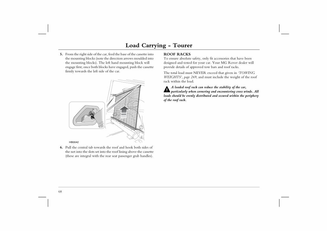
Load Carrying - Tourer5. From the right side of the car, feed the base of the cassette into
the mounting blocks (note the direction arrows moulded into the mounting blocks). The left hand mounting block will
ROOF RACKSTo ensure absolute safety, only fit accessories that have been designed and tested for your car. Your MG Rover dealer will
approved tow bars and roof racks.
st NEVER exceed that given in ‘TOWING 269, and must include the weight of the roof ad.
rack can reduce the stability of the car, hen cornering and encountering cross winds. All nly distributed and secured within the periphery
68
engage first; once both blocks have engaged, push the cassette firmly towards the left side of the car.
6. Pull the central tab towards the roof and hook both sides of the net into the slots set into the roof lining above the cassette (these are integral with the rear seat passenger grab handles).
provide details of
The total load muWEIGHTS’, pagerack within the lo
A loaded roofparticularly w
loads should be eveof the roof rack.
HB0042
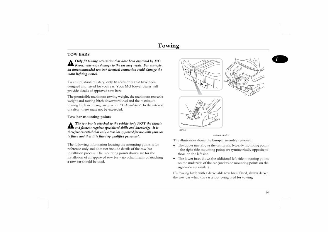
Towing
69
1Towing
Saloon models
ion shows the bumper assembly removed.er inset shows the centre and left-side mounting points t-side mounting points are symmetrically opposite to
the left side. er inset shows the additional left-side mounting points nderside of the car (underside mounting points on the e are similar).
itch with a detachable tow bar is fitted, always detach when the car is not being used for towing.
TOW BARS
Only fit towing accessories that have been approved by MG Rover, otherwise damage to the car may result. For example,
an unrecommended tow bar electrical connection could damage the main lighting switch.
To ensure absolute safety, only fit accessories that have been designed and tested for your car. Your MG Rover dealer will provide details of approved tow bars.
The permissible maximum towing weight, the maximum rear axle weight and towing hitch downward load and the maximum towing hitch overhang, are given in ‘Technical data’. In the interest of safety, these must not be exceeded.
Tow bar mounting points
The tow bar is attached to the vehicle body NOT the chassis and fitment requires specialised skills and knowledge. It is
therefore essential that only a tow bar approved for use with your car is fitted and that it is fitted by qualified personnel.
The following information locating the mounting points is for reference only and does not include details of the tow bar installation process. The mounting points shown are for the installation of an approved tow bar - no other means of attaching a tow bar should be used.
The illustrat• The upp
- the righthose on
• The lowon the uright-sid
If a towing hthe tow bar
H3001
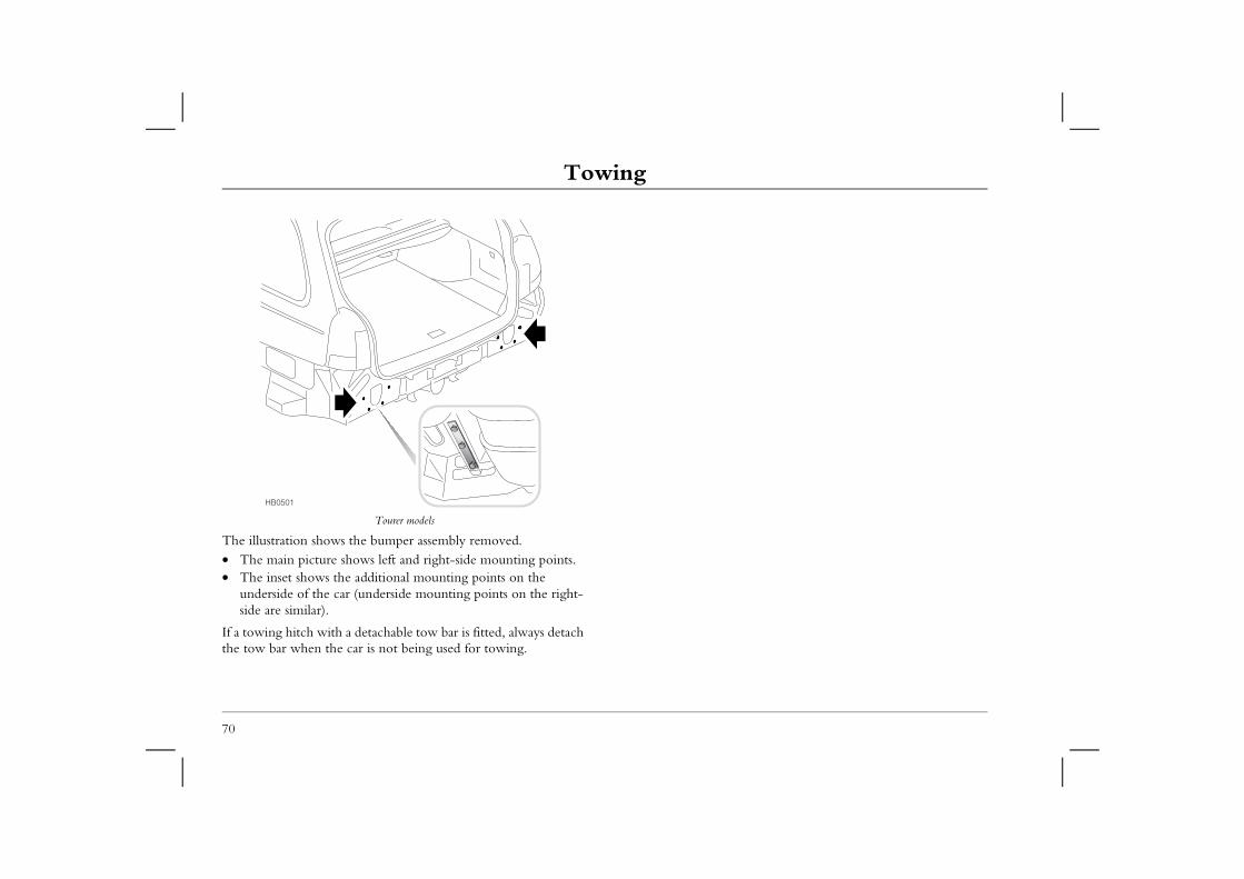
Towing
70
Tourer models
The illustration shows the bumper assembly removed.• The main picture shows left and right-side mounting points. • The inset shows the additional mounting points on the
underside of the car (underside mounting points on the right-side are similar).
If a towing hitch with a detachable tow bar is fitted, always detach the tow bar when the car is not being used for towing.
HB0501
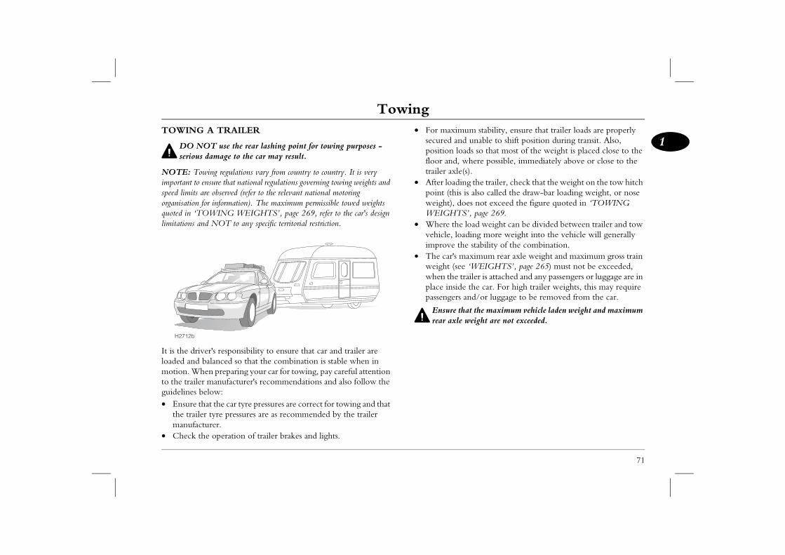
Towing
71
1imum stability, ensure that trailer loads are properly nd unable to shift position during transit. Also, loads so that most of the weight is placed close to the , where possible, immediately above or close to the le(s).ding the trailer, check that the weight on the tow hitch is is also called the draw-bar loading weight, or nose does not exceed the figure quoted in ‘TOWING TS’, page 269.e load weight can be divided between trailer and tow
loading more weight into the vehicle will generally the stability of the combination. maximum rear axle weight and maximum gross train see ‘WEIGHTS’, page 265) must not be exceeded, trailer is attached and any passengers or luggage are in
ide the car. For high trailer weights, this may require rs and/or luggage to be removed from the car.
that the maximum vehicle laden weight and maximum le weight are not exceeded.
TOWING A TRAILER
DO NOT use the rear lashing point for towing purposes - serious damage to the car may result.
NOTE: Towing regulations vary from country to country. It is very important to ensure that national regulations governing towing weights and speed limits are observed (refer to the relevant national motoring organisation for information). The maximum permissible towed weights quoted in ‘TOWING WEIGHTS’, page 269, refer to the car's design limitations and NOT to any specific territorial restriction.
It is the driver's responsibility to ensure that car and trailer are loaded and balanced so that the combination is stable when in motion. When preparing your car for towing, pay careful attention to the trailer manufacturer's recommendations and also follow the guidelines below:• Ensure that the car tyre pressures are correct for towing and that
the trailer tyre pressures are as recommended by the trailer manufacturer.
• Check the operation of trailer brakes and lights.
• For maxsecured aposition floor andtrailer ax
• After loapoint (thweight),WEIGH
• Where thvehicle, improve
• The car'sweight (when theplace inspassenge
Ensurerear ax
H2712b

2
2
Driving Controls
74 Instruments76 Trip Computer78 Warning Lights82 Message Centre88 Starting & Driving92 Catalytic Converter93 Environmental Driving95 Automatic Transmission99 Manual Gearbox
100 Fuel System104 Lights & Indicators110 Wipers & Washers112 Cruise Control114 Brakes118 Traction Control119 Parking Aid
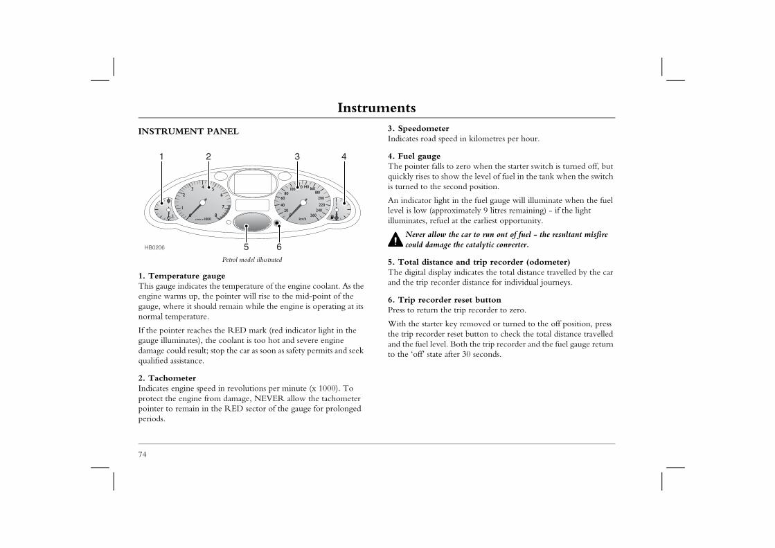
InstrumentsDriving ControlsInstrumentsINSTRUMENT PANEL 3. Speedometer
Indicates road speed in kilometres per hour.
o zero when the starter switch is turned off, but w the level of fuel in the tank when the switch
cond position.
in the fuel gauge will illuminate when the fuel ximately 9 litres remaining) - if the light at the earliest opportunity.
he car to run out of fuel - the resultant misfire the catalytic converter.
e and trip recorder (odometer) indicates the total distance travelled by the car er distance for individual journeys.
reset button trip recorder to zero.
ey removed or turned to the off position, press eset button to check the total distance travelled Both the trip recorder and the fuel gauge return ter 30 seconds.
74
Petrol model illustrated
1. Temperature gaugeThis gauge indicates the temperature of the engine coolant. As the engine warms up, the pointer will rise to the mid-point of the gauge, where it should remain while the engine is operating at its normal temperature.
If the pointer reaches the RED mark (red indicator light in the gauge illuminates), the coolant is too hot and severe engine damage could result; stop the car as soon as safety permits and seek qualified assistance.
2. TachometerIndicates engine speed in revolutions per minute (x 1000). To protect the engine from damage, NEVER allow the tachometer pointer to remain in the RED sector of the gauge for prolonged periods.
4. Fuel gaugeThe pointer falls tquickly rises to shois turned to the se
An indicator lightlevel is low (approilluminates, refuel
Never allow tcould damage
5. Total distancThe digital displayand the trip record
6. Trip recorderPress to return the
With the starter kthe trip recorder rand the fuel level. to the ‘off’ state af
1 2 4
5 6
3
HB0206
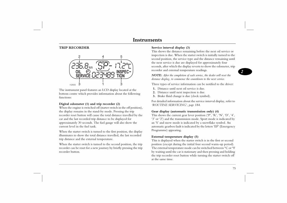
Instruments
75
2
erval display (3)the distance remaining before the next oil service or s due. When the starter switch is initially turned to the tion, the service type and the distance remaining until vice is due are displayed for approximately four r which the display reverts to show the odometer, trip external temperature readings.
er the completion of each service, the dealer will reset the ay, to commence the countdown to the next service.
of service information can be notified to the driver:e until next oil service is due.e until next inspection is due.luid change is due (clock symbol).
information about the service interval display, refer to SERVICING’, page 184.
ay (automatic transmission only) (4)the current gear lever position (‘P’, ‘R’, ‘N’, ‘D’, ‘4’, d the transmission mode. Sport mode is indicated by ow mode is indicated by a snowflake symbol. An
earbox fault is indicated by the letters ‘EP’ (Emergency ) appearing.
mperature display (5)ayed when the starter switch is in the first or second cept during the initial four second warm-up period). l temperature mode can be switched between °C or °F ntil the car is stationary and then pressing and holding rder reset button while turning the starter switch off time.
TRIP RECORDER
The instrument panel features an LCD display located at the bottom centre which provides information about the following functions:
Digital odometer (1) and trip recorder (2)When the engine is switched off (starter switch in the off position), the display remains in the stand-by mode. Pressing the trip recorder reset button will cause the total distance travelled by the car and the last recorded trip distance to be displayed for approximately 30 seconds. The fuel gauge will also show the current level in the fuel tank.
When the starter switch is turned to the first position, the display illuminates to show the total distance travelled, the last recorded trip distance and the external temperature.
When the starter switch is turned to the second position, the trip recorder can be reset for a new journey by briefly pressing the trip recorder button.
Service intThis shows inspection isecond posithe next serseconds, afterecorder and
NOTE: Aftdistance displ
Three types1. Distanc2. Distanc3. Brake f
For detailed‘ROUTINE
Gear displThis shows ‘3’ or ‘2’) anan ‘S’ and snautomatic gProgramme
External teThis is displposition (exThe externaby waiting uthe trip recoat the same
H2800 1
2
33
4 5
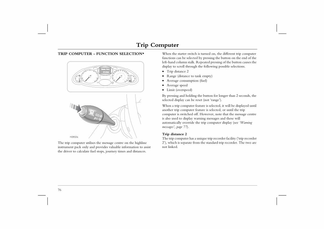
Trip ComputerTrip ComputerTRIP COMPUTER - FUNCTION SELECTION* When the starter switch is turned on, the different trip computer
functions can be selected by pressing the button on the end of the left-hand column stalk. Repeated pressing of the button causes the
rough the following possible selections.
e to tank empty)mption (fuel)
ed)
lding the button for longer than 2 seconds, the n be reset (not ‘range’).
uter feature is selected, it will be displayed until uter feature is selected, or until the trip ed off. However, note that the message centre lay warning messages and these will
rride the trip computer display (see ‘Warning .
has a unique trip recorder facility (‘trip recorder ate from the standard trip recorder. The two are
76
The trip computer utilises the message centre on the highline instrument pack only and provides valuable information to assist the driver to calculate fuel stops, journey times and distances.
display to scroll th• Trip distance 2• Range (distanc• Average consu• Average speed• Limit (overspe
By pressing and hoselected display ca
When a trip companother trip compcomputer is switchis also used to dispautomatically ovemessages’, page 77)
Trip distance 2The trip computer2’), which is separnot linked.
H2802a
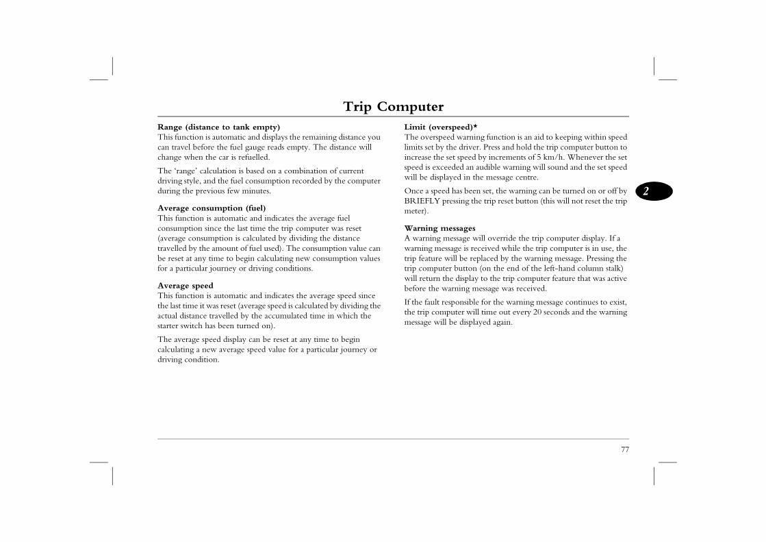
Trip Computer
77
2
rspeed)*ed warning function is an aid to keeping within speed
the driver. Press and hold the trip computer button to set speed by increments of 5 km/h. Whenever the set eeded an audible warning will sound and the set speed layed in the message centre.
d has been set, the warning can be turned on or off by ressing the trip reset button (this will not reset the trip
essagesessage will override the trip computer display. If a
ssage is received while the trip computer is in use, the will be replaced by the warning message. Pressing the er button (on the end of the left-hand column stalk) he display to the trip computer feature that was active arning message was received.
esponsible for the warning message continues to exist, puter will time out every 20 seconds and the warning l be displayed again.
Range (distance to tank empty)This function is automatic and displays the remaining distance you can travel before the fuel gauge reads empty. The distance will change when the car is refuelled.
The ‘range’ calculation is based on a combination of current driving style, and the fuel consumption recorded by the computer during the previous few minutes.
Average consumption (fuel)This function is automatic and indicates the average fuel consumption since the last time the trip computer was reset (average consumption is calculated by dividing the distance travelled by the amount of fuel used). The consumption value can be reset at any time to begin calculating new consumption values for a particular journey or driving conditions.
Average speedThis function is automatic and indicates the average speed since the last time it was reset (average speed is calculated by dividing the actual distance travelled by the accumulated time in which the starter switch has been turned on).
The average speed display can be reset at any time to begin calculating a new average speed value for a particular journey or driving condition.
Limit (oveThe overspelimits set byincrease thespeed is excwill be disp
Once a speeBRIEFLY pmeter).
Warning mA warning mwarning metrip feature trip computwill return tbefore the w
If the fault rthe trip commessage wil
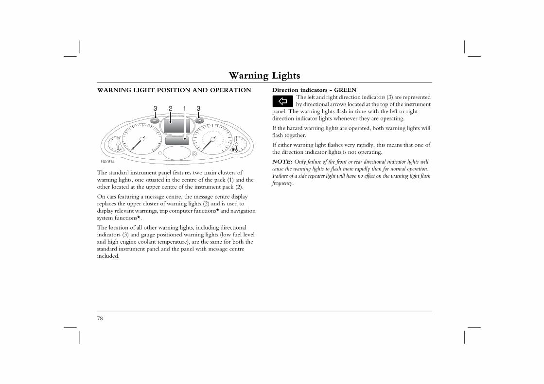
Warning LightsWarning LightsWARNING LIGHT POSITION AND OPERATION Direction indicators - GREEN
The left and right direction indicators (3) are represented by directional arrows located at the top of the instrument
g lights flash in time with the left or right r lights whenever they are operating.
ing lights are operated, both warning lights will
light flashes very rapidly, this means that one of ator lights is not operating.
re of the front or rear directional indicator lights will ghts to flash more rapidly than for normal operation. ater light will have no effect on the warning light flash
78
The standard instrument panel features two main clusters of warning lights, one situated in the centre of the pack (1) and the other located at the upper centre of the instrument pack (2).
On cars featuring a message centre, the message centre display replaces the upper cluster of warning lights (2) and is used to display relevant warnings, trip computer functions* and navigation system functions*.
The location of all other warning lights, including directional indicators (3) and gauge positioned warning lights (low fuel level and high engine coolant temperature), are the same for both the standard instrument panel and the panel with message centre included.
panel. The warnindirection indicato
If the hazard warnflash together.
If either warning the direction indic
NOTE: Only failucause the warning liFailure of a side repefrequency.
H2791a
123 3
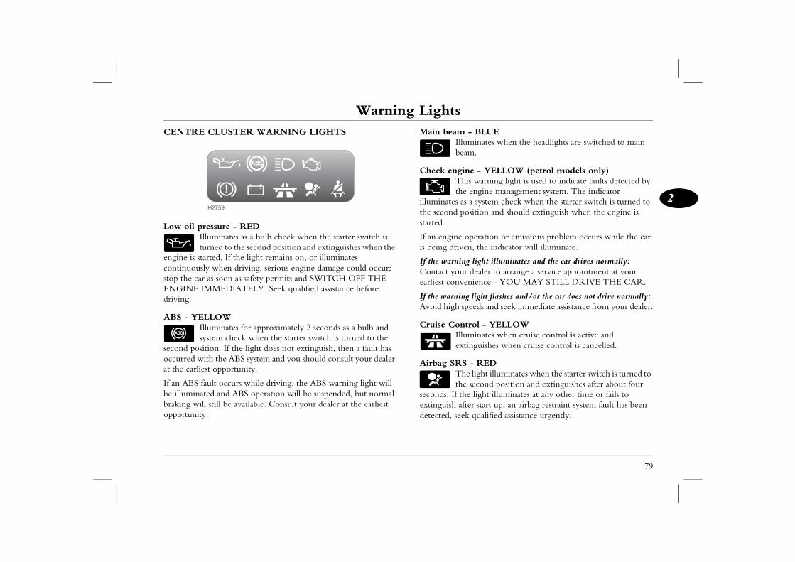
Warning Lights
79
2
- BLUE luminates when the headlights are switched to main am.
ine - YELLOW (petrol models only)his warning light is used to indicate faults detected by e engine management system. The indicator as a system check when the starter switch is turned to osition and should extinguish when the engine is
operation or emissions problem occurs while the car en, the indicator will illuminate.
ng light illuminates and the car drives normally: r dealer to arrange a service appointment at your enience - YOU MAY STILL DRIVE THE CAR.
ng light flashes and/or the car does not drive normally: speeds and seek immediate assistance from your dealer.
trol - YELLOWluminates when cruise control is active and tinguishes when cruise control is cancelled.
S - RED he light illuminates when the starter switch is turned to e second position and extinguishes after about four he light illuminates at any other time or fails to fter start up, an airbag restraint system fault has been ek qualified assistance urgently.
CENTRE CLUSTER WARNING LIGHTS
Low oil pressure - REDIlluminates as a bulb check when the starter switch is turned to the second position and extinguishes when the
engine is started. If the light remains on, or illuminates continuously when driving, serious engine damage could occur; stop the car as soon as safety permits and SWITCH OFF THE ENGINE IMMEDIATELY. Seek qualified assistance before driving.
ABS - YELLOWIlluminates for approximately 2 seconds as a bulb and system check when the starter switch is turned to the
second position. If the light does not extinguish, then a fault has occurred with the ABS system and you should consult your dealer at the earliest opportunity.
If an ABS fault occurs while driving, the ABS warning light will be illuminated and ABS operation will be suspended, but normal braking will still be available. Consult your dealer at the earliest opportunity.
Main beamIlbe
Check engTth
illuminates the second pstarted.
If an engineis being driv
If the warniContact youearliest conv
If the warniAvoid high
Cruise ConIlex
Airbag SRTth
seconds. If textinguish adetected, se
H2759
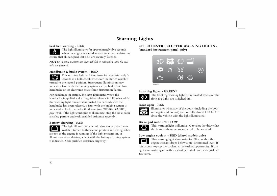
Warning LightsSeat belt warning - RED
The light illuminates for approximately five seconds when the engine is started as a reminder to the driver to
UPPER CENTRE CLUSTER WARNING LIGHTS - (standard instrument panel only)
- GREEN*nt fog warning light is illuminated whenever the g lights are switched on.
Dtes when any of the doors (including the boot te and bonnet) are not fully closed. DO NOT e vehicle with the light illuminated.
- YELLOWrning light is illuminated to alert the driver that e pads are worn and need to be serviced.
lant - RED (diesel models only)rning light illuminates for 20 seconds if the oolant drops below a pre-determined level. If
p the coolant at the earliest opportunity. If the ain within a short period of time, seek qualified
80
ensure that all occupied seat belts are securely fastened.
NOTE: In some markets the light will fail to extinguish until the seat belts are fastened.
Handbrake & brake system - REDThis warning light will illuminate for approximately 3 seconds as a bulb check whenever the starter switch is
turned to the second position. Subsequent illumination may indicate a fault with the braking system such as brake fluid loss, handbrake on or electronic brake force distribution failure.
For handbrake operation, the light illuminates when the handbrake is applied and extinguishes when it is fully released. If the warning light remains illuminated five seconds after the handbrake has been released, a fault with the braking system is indicated - check the brake fluid level (see ‘BRAKE FLUID’, page 196). If the light continues to illuminate, stop the car as soon as safety permits and seek qualified assistance urgently.
Battery charging - REDThe light illuminates as a bulb check when the starter switch is turned to the second position and extinguishes
as soon as the engine is running. If the light remains on, or illuminates when driving, a fault with the battery charging system is indicated. Seek qualified assistance urgently.
Front fog lightsThe frofront fo
Door open - REIlluminaor tailgadrive th
Brake pad wearThis wathe brak
Low engine cooThis waengine c
this occurs, top-ulight illuminates agassistance.
H3253
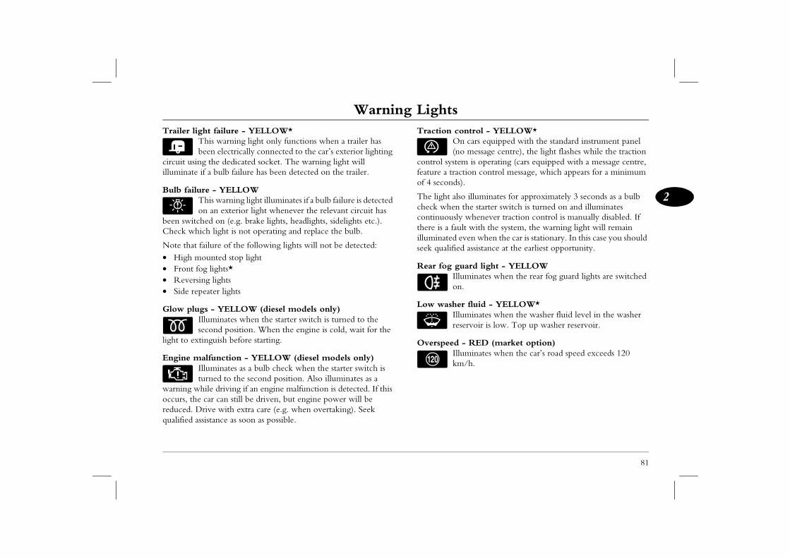
Warning Lights
81
2
ontrol - YELLOW*n cars equipped with the standard instrument panel o message centre), the light flashes while the traction m is operating (cars equipped with a message centre, ction control message, which appears for a minimum s).
so illuminates for approximately 3 seconds as a bulb the starter switch is turned on and illuminates y whenever traction control is manually disabled. If lt with the system, the warning light will remain
even when the car is stationary. In this case you should d assistance at the earliest opportunity.
uard light - YELLOWluminates when the rear fog guard lights are switched .
r fluid - YELLOW*luminates when the washer fluid level in the washer servoir is low. Top up washer reservoir.
- RED (market option)luminates when the car’s road speed exceeds 120
/h.
Trailer light failure - YELLOW*This warning light only functions when a trailer has been electrically connected to the car’s exterior lighting
circuit using the dedicated socket. The warning light will illuminate if a bulb failure has been detected on the trailer.
Bulb failure - YELLOWThis warning light illuminates if a bulb failure is detected on an exterior light whenever the relevant circuit has
been switched on (e.g. brake lights, headlights, sidelights etc.). Check which light is not operating and replace the bulb.
Note that failure of the following lights will not be detected:• High mounted stop light• Front fog lights*• Reversing lights• Side repeater lights
Glow plugs - YELLOW (diesel models only)Illuminates when the starter switch is turned to the second position. When the engine is cold, wait for the
light to extinguish before starting.
Engine malfunction - YELLOW (diesel models only)Illuminates as a bulb check when the starter switch is turned to the second position. Also illuminates as a
warning while driving if an engine malfunction is detected. If this occurs, the car can still be driven, but engine power will be reduced. Drive with extra care (e.g. when overtaking). Seek qualified assistance as soon as possible.
Traction cO(n
control systefeature a traof 4 second
The light alcheck whencontinuouslthere is a fauilluminated seek qualifie
Rear fog gIlon
Low washeIlre
OverspeedIlkm
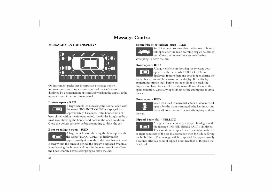
Message CentreMessage CentreMESSAGE CENTRE DISPLAY* Bonnet/boot or tailgate open - RED
Small icon used to warn that the bonnet or boot is still open after the main warning display has timed
. Close the bonnet/boot securely before e the car.
Darge vehicle icon showing the relevant door ned with the words ‘DOOR OPEN’ is layed. If more than one door is open during the ill be shown on the display. If the display
d-out) before the open door is closed, the by a small icon showing all four doors in the lose any open doors before attempting to drive
Dall icon used to warn that a door or doors are still n after the main warning display has timed-out. se all doors securely before attempting to drive
il - YELLOWarge vehicle icon with a dipped headlight with message ‘DIPPED BEAM FAIL’ is displayed. e icon shows a dipped beam headlight on the left of the car in accordance with the side suffering he message will be displayed for approximately ection of dipped beam headlights. Replace the
82
On instrument packs that incorporate a message centre, information concerning various aspects of the car’s status is displayed by a combination of icons and words in the display at the upper centre of the instrument panel.
Bonnet open - REDA large vehicle icon showing the bonnet open with the words ‘BONNET OPEN’ is displayed for approximately 4 seconds. If the bonnet has not
been closed within the timeout period, the display is replaced by a small icon showing the bonnet and boot in the open condition. Close the bonnet securely before attempting to drive the car.
Boot or tailgate open - REDA large vehicle icon showing the boot open with the words ‘BOOT OPEN’ is displayed for approximately 4 seconds. If the boot has not been
closed within the timeout period, the display is replaced by a small icon showing the bonnet and boot in the open condition. Close the boot securely before attempting to drive the car.
outattempting to driv
Door open - REA lopedisp
status check, this wextinguishes (timedisplay is replacedopen condition. Cthe car.
Door open - RESmopeClo
the car.
Dipped beam faA ltheTh
or right hand sidethe bulb failure. T4 seconds after selfailed bulb.
Message Centre
83
2
t fail - YELLOWA large vehicle icon with an active brake light with the message ‘BRAKE LIGHT FAIL’ is displayed. The icon shows a brake light on the same side of
e bulb failure. The message will be displayed for 4 rox. after pressing the brake pedal and the bulb failure ted. Replace the failed bulb.
lure of the high mounted stop lamp bulb will not be detected n the message centre.
ail - YELLOWA large vehicle icon with an active direction indicator with the message ‘INDICATOR FAIL’ is displayed. The icon shows the right or left hand
of the direction indicator which has failed (but will hether the indicator is at the front or rear). The l be displayed for approximately 4 seconds after direction indicators and the bulb failure being eplace the failed bulb.
ail - YELLOWA large vehicle icon with an active fog light with the message ‘FOG LIGHT FAIL’ is displayed. The icon shows the relevant location of the fog light
iled (front or rear and left or right side). The message layed for 4 seconds after operating the fog lights. failed bulb.
Main beam fail - YELLOWA large vehicle icon with a main headlight with the message ‘MAIN BEAM FAIL’ is displayed. The icon shows a main beam headlight on the left or
right hand side of the car in accordance with the side suffering the bulb failure. The message will be displayed for approximately 4 seconds after selection of main beam headlights. Replace the failed bulb.
Sidelight fail - YELLOWA large vehicle icon with an active sidelight with the message ‘SIDE LIGHT FAIL’ is displayed. The icon shows a sidelight on the same side of the car as
the bulb failure. The message will be displayed for approximately 4 seconds after selection of the lighting circuit. Replace the failed bulb.
Tail light fail - YELLOWA large vehicle icon with an active tail light with the message ‘TAIL LIGHT FAIL’ is displayed. The icon shows a tail light on the same side of the car as
the bulb failure. The message will be displayed for approximately 4 seconds after selection of the lighting circuit. Replace the failed bulb.
Brake ligh
the car as thseconds appbeing detec
NOTE: Faior displayed o
Indicator f
side locationnot show wmessage wilselecting thedetected. R
Fog light f
which has fawill be dispReplace the
Message CentreNumber plate light fail - YELLOW
A large vehicle icon with an active number plate light with the message ‘NO. PLATE LIGHT’ is
Low fuel level - YELLOWThis icon is displayed in addition to illumination of the low fuel warning light in the fuel gauge when
l in the fuel tank is down to the reserve level. yed with the message ‘LOW FUEL’ and econds. Refuel at the earliest opportunity.
lant temperature - REDis message is displayed in addition to mination of the high coolant temperature rning light in the temperature gauge whenever t rises to its maximum operating temperature. ed with the message ‘ENGINE OVERHEAT’.
lant - RED (diesel models only)is icon is displayed with the message ‘LOW OLANT’ for 20 seconds if the engine coolant ps below a pre-determined level. If this occurs, t at the earliest opportunity. If the message in a short period of time, seek qualified
lure - YELLOWis message is displayed together with the warning t in the centre cluster of the instrument panel en an ABS system fault has been detected. The ith the message ‘ABS FAULT’.
curs while driving, the ABS warning light S operation will be suspended. However
ill still be available. Consult your dealer at the ty.
84
displayed. The message will be displayed for approximately 4 seconds after turning on the side or headlights. Replace the failed bulb.
NOTE: A number plate light failure is only detected if both bulbs have failed.
Bulb failure - YELLOWIlluminates when the lights are switched on and a bulb failure is detected. The message ‘BULB FAILURE’ is also displayed. After approximately 4
seconds the message changes to a small icon.
NOTE: A summary of bulb failures is shown when the starter switch is turned off.
Lights on - YELLOWThe icon is displayed with the message ‘LIGHTS ON’. In addition, an audible warning chimes if the door is opened with the lights still switched on. The
message and icon are displayed for 10 seconds before reverting to an icon without text. The icon will be switched off after 1 minute if no further action is taken.
Rear fog guard lights on - YELLOWThe icon is displayed with the message ‘REAR FOG ON' when the rear fog guard lights have been selected. The message is first displayed as a large
icon for 4 seconds, after which it reduces to a small icon while the lights remain on.
fueThe icon is displailluminates for 4 s
High engine cooThilluwa
the engine coolanThe icon is display
Low engine cooThCOdro
top-up the coolanappears again withassistance.
ABS System faiThlighwh
icon is displayed w
If an ABS fault ocilluminates and ABnormal braking wearliest opportuni
Message Centre
85
2
low - YELLOWThis icon is displayed with the message ‘BRAKE PADS LOW’ and alerts the driver that the brake pads are worn and need to be serviced. The
large icon are displayed for 4 seconds, after which icon is displayed for as long as the condition exists. ake pads checked and/or replaced.
/Electronic brake distribution failure - REDThis message is displayed (together with the dedicated warning light in the centre cluster of the instrument panel) to alert the driver of a brake
re. The icon is displayed continuously while a fault the message ‘BRAKE FAULT’ appearing for 4 eck the brake fluid level (see ‘BRAKE FLUID’, f the warning continues to illuminate, seek qualified gently.
S malfunction - REDThis message is displayed (together with the dedicated warning light in the centre cluster of the instrument panel) to alert the driver of a SRS
re. The icon appears with the message ‘AIRBAG r 4 seconds, but is not displayed during the initial start-e. If this warning appears, the airbag/SRS system will operational, seek qualified assistance urgently.
No battery charge warning - REDThis message is displayed (together with the dedicated warning light in the centre cluster of the instrument panel) when a battery charging problem
has been detected. The icon is displayed with the message ‘CHARGE FAULT’. The message is only displayed when the engine has been running at over 400 rev/min for more than 5 seconds, and is displayed for as long as the condition exists.
Low oil pressure - REDThis message is displayed (together with the dedicated warning light in the centre cluster of the instrument panel) when engine oil pressure is
dangerously low and liable to result in engine damage. The icon is displayed with the message ‘LOW OIL PRESSURE’. The message is only displayed when the engine has been running at greater than 400 rev/min for more than 5 seconds, and is displayed for as long as the condition exists. Stop the car as soon as safety permits and SWITCH OFF THE ENGINE IMMEDIATELY. Seek qualified assistance before driving.
Seat belt warning - REDThis message is displayed (together with the dedicated warning light in the centre cluster of the instrument panel) when the engine is started, as a
reminder to the driver to ensure that all occupied seat belts are securely fastened. The icon is displayed with the message ‘SEAT BELT PLEASE’.
Brake pad
message andtime a smallHave the br
Brake fluid
system failuexists, with seconds. Chpage 196). Iassistance ur
Airbag SR
system failuFAULT’ foup procedurnot be fully
Message CentreEngine malfunction - YELLOW (diesel models only)
This warning icon illuminates with the message ‘CHECK ENGINE’ if an engine malfunction is
Trailer light fail - YELLOW*This warning message only functions when a trailer has been electrically connected to the car's exterior
t circuit using the dedicated socket. The ill be displayed if a bulb failure has been
ailer. The icon is displayed with the message ’.
d level - YELLOWplayed when the fluid level in the washer rvoir is low. The icon is displayed with the
ssage ‘LOW WASHER FLUID’ for 4 seconds activated, and also at start up and shut down. servoir.
ation (Diesel only) - YELLOWplayed at start up when the starter switch is in second position until the glow plug temperature been reached. The icon is displayed with the PLUG ON’. Do not start the engine until the as been extinguished.
rtia) switch - YELLOWplayed if the inertia switch has tripped. The icon isplayed with the message ‘INERTIA ITCH’. The car will not start until the inertia set (see ‘FUEL CUT-OFF SWITCH’,
86
detected while driving. If this occurs, the car can still be driven, but engine power will be reduced. Drive with extra care (when overtaking, for example) and seek qualified assistance as soon as possible.
Check engine - YELLOW (petrol models only)This warning icon is used to indicate faults detected by the engine management system. If an engine operation or emissions problem occurs while the
car is being driven, the icon is displayed with the message ‘CHECK ENGINE’.
If ‘Check engine’ illuminates, and the car drives normally: Contact your dealer to arrange a service appointment at your earliest convenience - YOU MAY STILL DRIVE THE CAR.
If ‘Check engine’ illuminates and the warning light also flashes (see ‘Warning lights’) and/or the car does not drive normally: Avoid high speeds and seek immediate assistance from your dealer.
Traction control operation/malfunction - YELLOW*The warning illuminates for approximately 4 seconds while traction control is operating and illuminates continuously while traction control is
manually disabled. The icon is displayed with the message ‘TRACTION CONTROL’. If the warning stays on, a fault with the system is indicated; seek qualified assistance.
lighwarning message wdetected on the tr‘BULB FAILURE
Low washer fluiDisreseme
when it is initiallyTop up washer re
Glow plug operDisthehas
message ‘GLOW warning message h
Fuel cut-off (ineDisis dSW
switch has been repage 103).
Message Centre
87
2
Handset (key) battery low - REDDisplayed if the instrument pack detects that the handset battery is low. The icon is displayed with the message ‘KEY BATTERY LOW’. Replace the
handset battery at the earliest opportunity (see ‘REMOTE HANDSET BATTERY’, page 16).
Low battery mode - YELLOWDisplayed when the battery voltage is less than 10V and extinguishes when the battery voltage rises above 11V. The display is extinguished during
engine cranking and for a further five seconds after cranking. The icon is displayed with the message ‘LOW BATTERY’. If the message remains illuminated recharge battery or seek qualified assistance.
Engine disabled - YELLOWDisplayed if the engine has been disabled (immobilised - see ‘ENGINE IMMOBILISATION’, page 7). The icon is
displayed with the message ‘ENGINE DISABLED’.
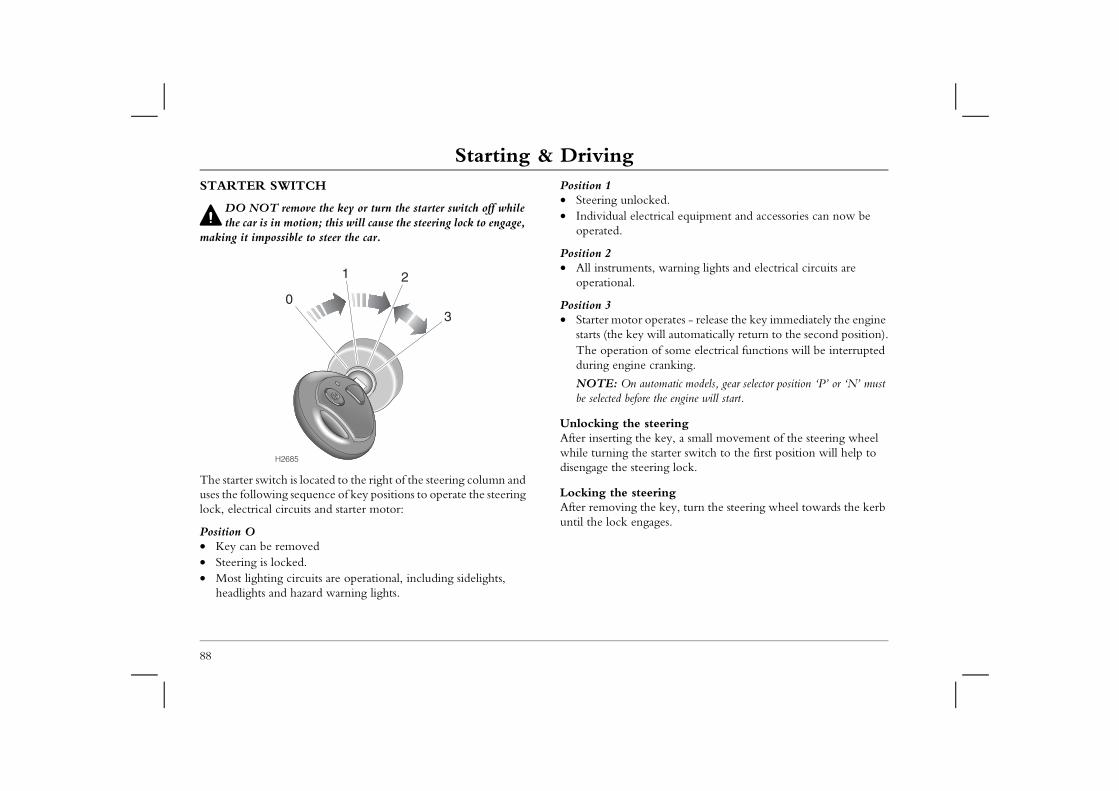
Starting & DrivingStarting & DrivingSTARTER SWITCH
DO NOT remove the key or turn the starter switch off while
Position 1• Steering unlocked.
trical equipment and accessories can now be
s, warning lights and electrical circuits are
perates - release the key immediately the engine ill automatically return to the second position).
of some electrical functions will be interrupted cranking.
tomatic models, gear selector position ‘P’ or ‘N’ must the engine will start.
teering key, a small movement of the steering wheel starter switch to the first position will help to ring lock.
ring e key, turn the steering wheel towards the kerb ages.
88
the car is in motion; this will cause the steering lock to engage, making it impossible to steer the car.
The starter switch is located to the right of the steering column and uses the following sequence of key positions to operate the steering lock, electrical circuits and starter motor:
Position O • Key can be removed• Steering is locked.• Most lighting circuits are operational, including sidelights,
headlights and hazard warning lights.
• Individual elecoperated.
Position 2• All instrument
operational.
Position 3• Starter motor o
starts (the key wThe operationduring engine
NOTE: On aube selected before
Unlocking the sAfter inserting thewhile turning the disengage the stee
Locking the steeAfter removing thuntil the lock eng
H2685
1 2
30
Starting & Driving
89
2
if the engine fails to start, or starts but will not unning: accelerator pedal half way down while operating the O NOT operate the starter for more than 15 seconds se the accelerator as soon as the engine starts.ine still fails to start, operate the starter again, this time ressing the accelerator pedal to clear the engine of el. Ensure the starter motor is not operated for more econds and release the accelerator as soon as the engine
T pump the accelerator pedal during starting.
PETROL MODELS
Never start or leave the engine running in an unventilated building - exhaust gases are poisonous and contain carbon
monoxide, which can cause unconsciousness and may even be fatal.
Catalytic converters can be damaged if the wrong fuel is used, or if an engine misfire occurs. Before starting the engine, you
should be aware of the precautions detailed under ‘CATALYTIC CONVERTER’, page 92.
Starting the engine 1. Check that the handbrake is on and that the gear lever is in
neutral (‘P’ or ‘N’ for automatic transmission).2. Switch off all unnecessary electrical equipment (including the
air conditioning).3. Turn the starter key to the third position and release the key
as soon as the engine has started.
NOTE: Continued use of the starter will not only discharge the battery, but may damage the starter motor and the catalytic converter.
DO NOT press the accelerator pedal while starting and DO NOT operate the starter for more than 15 seconds at a time. If the engine fails to start, switch off and wait for at least 10 seconds before trying again.
What to docontinue r• Press the
starter. Dand relea
• If the engfully depexcess futhan 15 sstarts.
• DO NO
Starting & DrivingDIESEL MODELS
Never start, or leave the engine running, in an unventilated Precautions
ine must not be run above fast idle speed until the rning light extinguishes. This will ensure that the bo-charger bearings are properly lubricated before eed. the engine to idle for 10 seconds before switching
90
building - exhaust gases are poisonous and contain carbon monoxide, which can cause unconsciousness and may even be fatal.
Catalytic converters can be damaged if the wrong fuel is used, or if an engine misfire occurs. Before starting the engine, you
should be aware of the precautions detailed under ‘CATALYTIC CONVERTER’, page 92.
Starting the engine1. Check that the handbrake is applied and that the gear lever is
in neutral (‘P’ or ‘N’ for automatic transmission).2. Switch off all unnecessary electrical equipment (including the
air conditioning).3. Insert the key and turn the starter switch to the second
position. Wait until the glow plug warning light extinguishes.4. Turn the key to the third position to operate the starter
motor; DO NOT press the accelerator pedal during starting and release the key as soon as the engine is running.
NOTE: Continued use of the starter will not only discharge the battery, but may damage the starter motor and the catalytic converter.
If the engine stalls, you MUST turn the starter switch fully off before turning the starter switch back to the second position. Then wait until the glow plug warning light goes out before attempting to restart; the engine will not start after stalling by turning the starter switch from the second position.
In temperate climates, DO NOT operate the starter switch for longer than 5 seconds; if the engine fails to start, switch off and wait for 10 seconds before re-using the starter.
• The diesel engoil pressure waengine and turbeing run at sp
• ALWAYS allowoff.
Starting & Driving
91
2
G-IN, gearbox, brakes and tyres need time to ‘bed-in’ and demands of everyday motoring. During the first
t is essential that you drive with consideration for the process and heed the following advice:llow the engine to exceed 3,000 rev/min in any gear.perate at full throttle in any gear.llow the engine to labour in any gear.avy braking where possible.
nning-in distance has been completed, engine speeds ually increased.
ALL MODELSCold climatesIn temperatures of -10° C and below, engine cranking times will increase. As the starter motor may need to operate for longer, it is essential that all unnecessary electrical equipment is switched off while cranking.
NOTE: When starting manual transmission vehicles in freezing conditions or when the battery is in a low state of charge, depress the clutch before starting and hold it down until the engine is running.
Warming upIn the interest of fuel economy, it is advisable to drive the car soon after starting. Remember that harsh acceleration, or labouring the engine before the normal operational temperature has been reached, can damage the engine.
ParkingAfter bringing the car to a stop, ALWAYS apply the handbrake and select neutral (‘P’ for automatic transmission), before releasing the foot brake and switching off the engine.
Towing - switching offAfter periods of strenuous towing (particularly at high altitude or in hot weather), it is good practice to allow the engine to idle for a few minutes before switching off. This will enable the engine cooling system to continue operating for a while in order to reduce underbonnet heat.
RUNNINThe engineadjust to the1,000 km, irunning-in • Do not a• Do not o• Do not a• Avoid he
After the rucan be grad
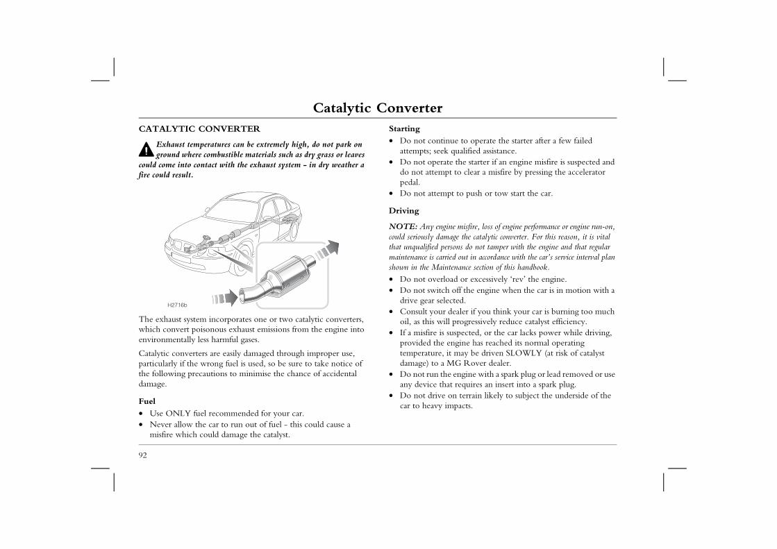
Catalytic ConverterCatalytic ConverterCATALYTIC CONVERTER
Exhaust temperatures can be extremely high, do not park on
Starting• Do not continue to operate the starter after a few failed
qualified assistance. the starter if an engine misfire is suspected and to clear a misfire by pressing the accelerator
t to push or tow start the car.
e misfire, loss of engine performance or engine run-on, ge the catalytic converter. For this reason, it is vital ons do not tamper with the engine and that regular d out in accordance with the car’s service interval plan enance section of this handbook.ad or excessively ‘rev’ the engine.off the engine when the car is in motion with a ted.ealer if you think your car is burning too much
progressively reduce catalyst efficiency.spected, or the car lacks power while driving,
ngine has reached its normal operating may be driven SLOWLY (at risk of catalyst G Rover dealer.
engine with a spark plug or lead removed or use t requires an insert into a spark plug.n terrain likely to subject the underside of the pacts.
92
ground where combustible materials such as dry grass or leaves could come into contact with the exhaust system - in dry weather a fire could result.
The exhaust system incorporates one or two catalytic converters, which convert poisonous exhaust emissions from the engine into environmentally less harmful gases.
Catalytic converters are easily damaged through improper use, particularly if the wrong fuel is used, so be sure to take notice of the following precautions to minimise the chance of accidental damage.
Fuel• Use ONLY fuel recommended for your car.• Never allow the car to run out of fuel - this could cause a
misfire which could damage the catalyst.
attempts; seek • Do not operate
do not attemptpedal.
• Do not attemp
Driving
NOTE: Any engincould seriously damathat unqualified persmaintenance is carrieshown in the Maint• Do not overlo• Do not switch
drive gear selec• Consult your d
oil, as this will• If a misfire is su
provided the etemperature, itdamage) to a M
• Do not run theany device tha
• Do not drive ocar to heavy im
H2716b
Environmental Driving
93
2
Environmental Driving le which you drive your car has a significant bearing on tal pollution, as well as affecting the amount of fuel
ll throttle accelerationather than rapid, acceleration uses considerably less ces exhaust pollutants and also minimises the wear to
cal components.iving at maximum speedsumption, exhaust emissions and noise levels all significantly at high speeds. For example, travelling at h uses up to 20 per cent less fuel than driving at h. rive in a low gear for longer than necessaryin lower gears uses more fuel and creates more noise. up to a higher gear as soon as possible, provided it does use the engine to labour. oothlyting obstructions and slowing down well in advance, e need for unnecessary acceleration and harsh braking. h driving style not only reduces fuel consumption, but ce the emission of poisonous gases by two thirds or
ff the engine when waiting in traffic is obvious that the car will be stationary for several or more, and provided it is safe to do so, switch off the he impact on the environment of starting the engine
ll be less than the effect of allowing the engine to idle conds or more.
PROTECTING THE ENVIRONMENTEnvironmental issues are increasingly influencing our lives, and the motor car is sometimes seen as a major source of air pollution.
In a great many respects, however, criticism of the car and its manufacturer is misplaced, for few industries have done more to reduce pollution than the motor industry. MG Rover is no exception. Your car has been designed with the latest technology in order to minimise the environmental impact of exhaust emissions. Even so, any further reduction in emissions is in everyone's interest and, to this end, there are a number of ways in which you, the owner, can also make a contribution.
Starting the engineAlthough it is a common perception that cars should be ‘warmed up’ before being driven, this is not the case.
The majority of poisonous emissions are produced immediately following a cold start and in the period while the engine is warming up. Because the car warms up much faster while it is being driven, it is less harmful to the environment to drive away immediately after starting rather than to allow the engine to idle.
Driving styThe way inenvironmenyou use:• Avoid fu
Steady, rfuel, redumechani
• Avoid drFuel conincrease 100 km/112 km/
• Do not dDriving Change NOT ca
• Drive smAnticipaavoids thA smootcan redumore.
• Switch oWhen itminutes engine. Tagain wifor 45 se
Environmental DrivingMaintenance• Have the car regularly serviced
94
Regular servicing from a qualified technician will ensure optimum fuel economy and minimise exhaust pollutants, as well as effectively extending the service life of the car.
• Check the tyre pressures regularlyUnder-inflated tyres increase the rolling resistance of the car which, in turn, increases fuel consumption. Over or under-inflated tyres wear out more rapidly and also have a detrimental effect on the car's handling characteristics.
• Do not carry unnecessary loadsThe additional weight of unnecessary loads wastes fuel, especially in stop/start conditions where the car is frequently required to set off from stationary.
• Remove roof racksThe additional air resistance created by roof racks and carriers increase drag and waste fuel (an unladen roof rack can increase fuel consumption by as much as 0.3 l/100km.
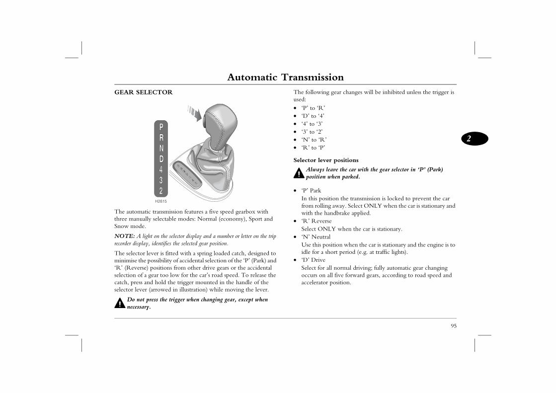
Automatic Transmission
95
2
Automatic Transmission ng gear changes will be inhibited unless the trigger is
’’
’’
ver positions
s leave the car with the gear selector in ‘P’ (Park) n when parked.
osition the transmission is locked to prevent the car ing away. Select ONLY when the car is stationary and handbrake applied.erseNLY when the car is stationary.tralposition when the car is stationary and the engine is to short period (e.g. at traffic lights).er all normal driving; fully automatic gear changing n all five forward gears, according to road speed and or position.
GEAR SELECTOR
The automatic transmission features a five speed gearbox with three manually selectable modes: Normal (economy), Sport and Snow mode.
NOTE: A light on the selector display and a number or letter on the trip recorder display, identifies the selected gear position.
The selector lever is fitted with a spring loaded catch, designed to minimise the possibility of accidental selection of the ‘P’ (Park) and ‘R’ (Reverse) positions from other drive gears or the accidental selection of a gear too low for the car’s road speed. To release the catch, press and hold the trigger mounted in the handle of the selector lever (arrowed in illustration) while moving the lever.
Do not press the trigger when changing gear, except when necessary.
The followiused:• ‘P’ to ‘R• ‘D’ to ‘4• ‘4’ to ‘3’• ‘3’ to ‘2’• ‘N’ to ‘R• ‘R’ to ‘P
Selector le
Alwaypositio
• ‘P’ ParkIn this pfrom rollwith the
• ‘R’ RevSelect O
• ‘N’ NeuUse this idle for a
• ‘D’ DrivSelect fooccurs oaccelerat
H2815
Automatic Transmission• ‘4’ (1st, 2nd, 3rd and 4th gears)
Automatic gear changing is limited to the lower four gears only; Gear change speedsWith ‘D’ selected, the road speeds at which gear changes take place will vary according to the position of the accelerator: minimum
esult in gear changes at low road speeds, while nings will cause the gearbox to delay gear r road speeds have been reached (thereby of acceleration).
r changes can be made to occur at a wide range ending on accelerator position.
acceleration for overtaking, push the accelerator xtent of its travel in a single, quick movement kick-down’). Up to a certain speed, this will te downshift into the lowest appropriate gear, acceleration. Once the pedal is relaxed, normal s will resume (dependent upon road speed and osition).
96
use this position for town driving and on winding country roads.
• ‘3’ (1st, 2nd and 3rd gears)Automatic gear changing is limited to the lower three gears only; use this position in congested traffic conditions. This position also provides moderate engine braking for descending slopes.
• ‘2’ (1st and 2nd gears)Automatic gear changing is limited to first and second gears only; use when driving up steep gradients and for negotiating very narrow, twisting roads. This position also provides more pronounced engine braking for descending steep slopes.
Using the automatic transmissionThe following information is important - particularly for drivers who are unused to driving cars with automatic transmission.• Before starting the engine, ensure that both foot brake and
handbrake are applied.• After starting the engine, KEEP BOTH BRAKES APPLIED
before and whilst moving the selector lever to the required drive position.
• Keep the brakes applied until you are ready to move - an ‘automatic’ will tend to creep forward (or backward) without throttle application, as soon as the brakes are released.
• Never 'rev' the engine while selecting a drive gear, or while the car is stationary with a drive gear selected - an ‘automatic’ will move immediately the accelerator pedal is pressed.
acceleration will rlarger throttle opechanges until fasteincreasing the rate
With practice, geaof road speeds dep
‘Kick-down’To provide rapid pedal to the full e(this is known as ‘cause an immediafollowed by rapidgear change speedaccelerator pedal p
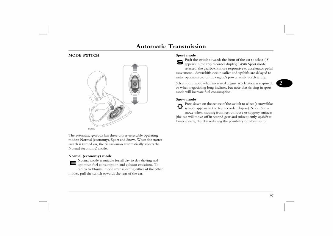
Automatic Transmission
97
2
ethe switch towards the front of the car to select (‘S’ rs in the trip recorder display). With Sport mode ed, the gearbox is more responsive to accelerator pedal - downshifts occur earlier and upshifts are delayed to um use of the engine's power while accelerating.
mode when increased engine acceleration is required, gotiating long inclines, but note that driving in sport ncrease fuel consumption.
edown on the centre of the switch to select (a snowflake l appears in the trip recorder display). Select Snow
when moving from rest on loose or slippery surfaces move off in second gear and subsequently upshift at s, thereby reducing the possibility of wheel spin).
MODE SWITCH
The automatic gearbox has three driver-selectable operating modes: Normal (economy), Sport and Snow. When the starter switch is turned on, the transmission automatically selects the Normal (economy) mode.
Normal (economy) modeNormal mode is suitable for all day to day driving and optimises fuel consumption and exhaust emissions. To return to Normal mode after selecting either of the other
modes, pull the switch towards the rear of the car.
Sport modPush appeaselect
movement make optim
Select sportor when nemode will i
Snow modPress symbomode
(the car willlower speed
H2827
Automatic TransmissionAUTOMATICALLY SELECTED MODES
NOTE: Automatically selected modes cannot be selected by the driver and
• Cruise control modeWhen cruise control (if fitted) is activated, a suitable gear
is selected which is less sensitive to throttle educes the amount and frequency of gear
ding a smoother ride.odenditions the automatic transmission will stay in
s for longer, to help the engine reach its normal erature more quickly. This will help to improve nomy and driveability, and reduce emissions. temperature modet temperatures during extreme load conditions, r the engine and the gearbox to overheat. At a ature, the transmission will select a gear change d to aid the cooling process, whilst enabling the tinue performing normally in high temperatures.ge modeis reduced during gear changes, creating a much
98
will not operate if Sport or Snow mode are selected.
The transmission control system automatically selects different gear change modes, listed below, designed to suit a variety of driving conditions. • Hill ascent, trailer and high altitude mode
A suitable gear change pattern is selected to counter momentum loss, caused by the more frequent gear changing which can occur when climbing hills, or when towing a trailer or caravan. This gear change pattern is also selected at high altitudes to combat low engine torque.
• Hill descent modeUnless some form of braking is applied, vehicles will naturally increase speed when travelling down hill. On most automatic vehicles, this results in the highest gear being selected, thereby reducing engine braking to a minimum.On this car however, the hill descent mode applies a brake within the transmission and, depending on circumstances, changes to a lower gear, or (more commonly on diesel engine cars) inhibits automatic selection of higher gears. Hill descent mode will only be activated when the accelerator pedal is fully released, and when some braking effort has been applied but a certain amount of acceleration is still occurring. The precise operating parameters of hill decent mode will differ according to engine type.
NOTE: Hill descent mode is not designed to be driver-activated, or to replace the good practice of selecting an appropriate low gear for steep descents, or making normal use of the brakes at all times.
change patternchanges. This rchanges, provi
• Cold start mIn very cold cothe lower gearoperating tempoverall fuel eco
• High coolantIn high ambienit is possible focertain temperpattern designegearbox to con
• Smooth chanEngine torque smoother ride.
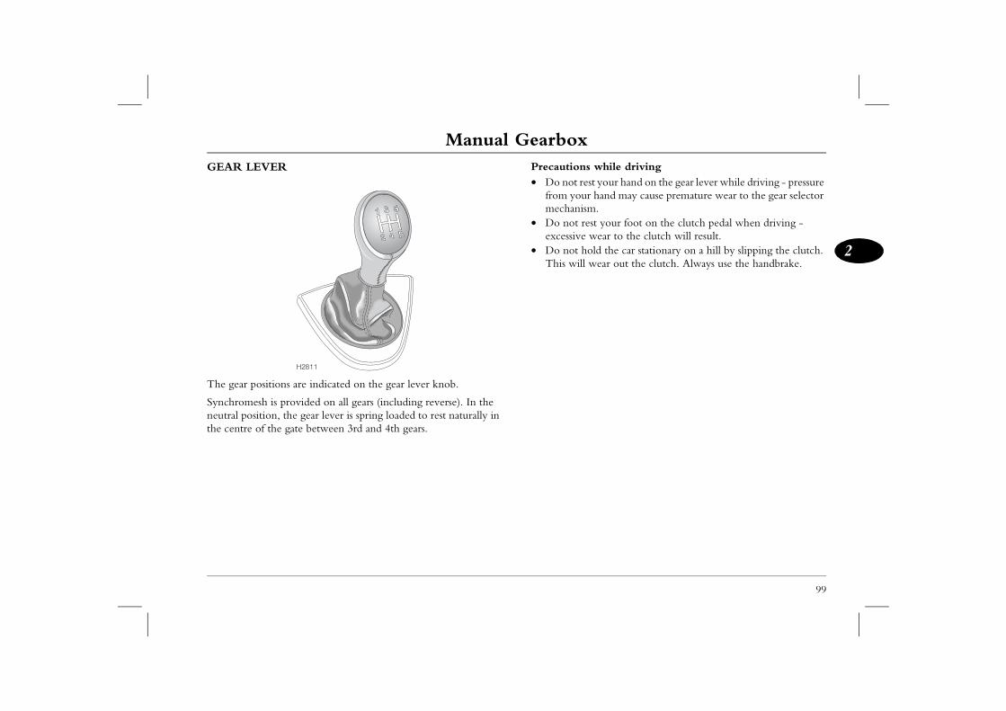
Manual Gearbox
99
2
Manual Gearbox s while drivingest your hand on the gear lever while driving - pressure r hand may cause premature wear to the gear selector
sm.est your foot on the clutch pedal when driving - wear to the clutch will result.old the car stationary on a hill by slipping the clutch.
l wear out the clutch. Always use the handbrake.
GEAR LEVER
The gear positions are indicated on the gear lever knob.
Synchromesh is provided on all gears (including reverse). In the neutral position, the gear lever is spring loaded to rest naturally in the centre of the gate between 3rd and 4th gears.
Precaution• Do not r
from youmechani
• Do not rexcessive
• Do not hThis wil
H2811
Fuel SystemFuel SystemTYPE OF FUELPetrol engines
Diesel engines
Diesel fuel specification: Good quality diesel fuel to EN 590
sel fuel can vary in different countries and only y fuel should be used. It is important that the diesel fuel does not exceed 0.3%. In Europe, all within this limit, but in other parts of the world, with your supplier.
HE FORECOURT
ses are highly inflammable and, in confined so extremely explosive.
hen refuelling:engine. or use a naked flame.obile phone.
fuel.l the tank.
100
Petrol fuel specification: 95 RON unleaded petrol to EN 228 specification.
The RON value (octane rating) and type of petroleum (unleaded or leaded) available at garage forecourts, will vary in different parts of the world. For example, in most European countries 95 RON unleaded fuel is readily available, but in other parts of the world fuel supplies may be limited to leaded or lower octane fuels only.
Before a new car is delivered to the first owner, the engine is tuned to suit the fuel supplies commonly available in the market in which the car is to be purchased. However, if the car is later exported to a different country, or is used to travel between different territories, you should be aware that the available fuel supplies may not be compatible with the engine specification. If in doubt, consult an MG Rover dealer for advice.
The RON value quoted above is a MINIMUM requirement for the United Kingdom and most European markets and can be safely exceeded. For optimum engine performance, 98 RON unleaded petrol should be used.
IN AN EMERGENCY (and only if the correct fuel is unavailable), lower octane rated fuel can be used for very limited periods of moderate, low speed motoring, provided engine ‘knocking’ does not occur.
specification.
The quality of dieclean, good qualitsulphur content ofsupplies should beyou should check
SAFETY ON T
Petroleum gaspaces, are al
Always take care w• Switch off the • Do not smoke• Do not use a m• Avoid spilling • Do not overfil
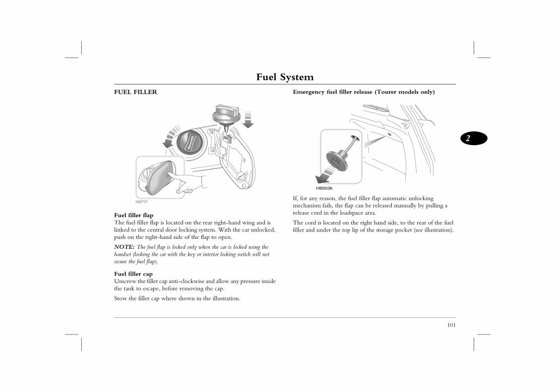
Fuel System
101
2
y fuel filler release (Tourer models only)
eason, the fuel filler flap automatic unlocking fails, the flap can be released manually by pulling a in the loadspace area.
located on the right hand side, to the rear of the fuel der the top lip of the storage pocket (see illustration).
0036
FUEL FILLER
Fuel filler flapThe fuel filler flap is located on the rear right-hand wing and is linked to the central door locking system. With the car unlocked, push on the right-hand side of the flap to open.
NOTE: The fuel flap is locked only when the car is locked using the handset (locking the car with the key or interior locking switch will not secure the fuel flap).
Fuel filler capUnscrew the filler cap anti-clockwise and allow any pressure inside the tank to escape, before removing the cap.
Stow the filler cap where shown in the illustration.
Emergenc
If, for any rmechanism release cord
The cord isfiller and un
H2717
HB
Fuel SystemFUEL FILLING
Use only the recommended fuel! Serious damage to the catalytic
Empty fuel tankNever allow the car to run out of fuel - the resultant misfire could destroy the catalytic converter. In the event of the fuel tank
art the engine carefully after refuelling. If the evenly, switch off and contact your MG Rover ttempting to restart the engine.he fuel system will prime automatically and the started.
102
converter will occur if the wrong fuel is used.
Always fill the tank SLOWLY, until the filler nozzle automatically cuts-off the fuel supply. DO NOT attempt to fill the tank beyond this point, or spillage could result due to expansion of the fuel.
Petrol enginesThe filler tube is designed to accept a narrow filler nozzle, of the type found on pumps that deliver ONLY unleaded fuel. A flap lies across the filler neck; insert the nozzle sufficiently to fully open the flap before filling.
DO NOT fully fill the tank if the vehicle is to be parked in direct sunlight, or high ambient temperature - expansion of the
fuel could cause spillage.
Diesel enginesThe diesel fuel filling system on garage forecourts is designed to fill at a maximum of 45 litres per minute. Use of commercial vehicle diesel pumps with a higher fill rate may result in premature pump cut-off and fuel spillage.
running dry:• Petrol engine: St
engine runs undealer before a
• Diesel engine: Tengine can be
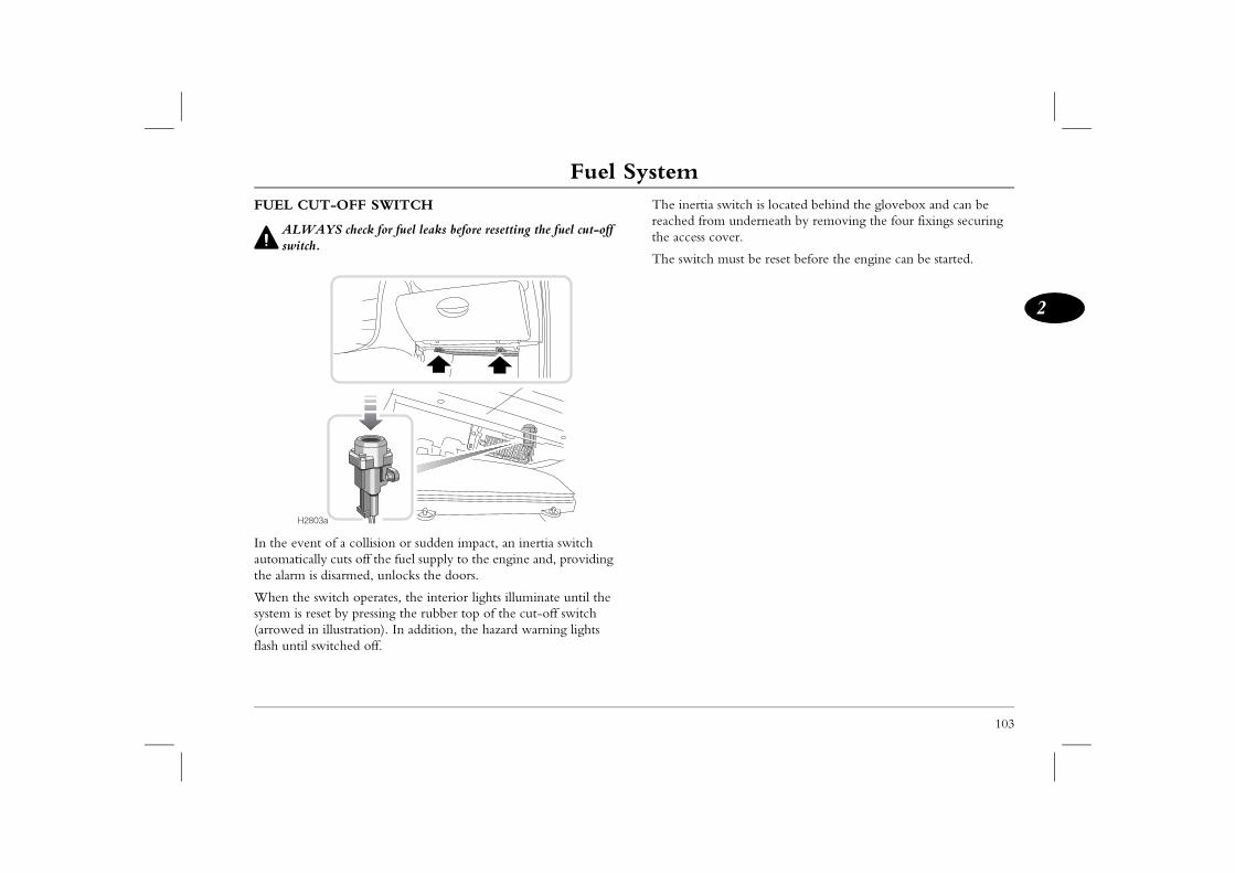
Fuel System
103
2
switch is located behind the glovebox and can be underneath by removing the four fixings securing
over.
must be reset before the engine can be started.
FUEL CUT-OFF SWITCH
ALWAYS check for fuel leaks before resetting the fuel cut-off switch.
In the event of a collision or sudden impact, an inertia switch automatically cuts off the fuel supply to the engine and, providing the alarm is disarmed, unlocks the doors.
When the switch operates, the interior lights illuminate until the system is reset by pressing the rubber top of the cut-off switch (arrowed in illustration). In addition, the hazard warning lights flash until switched off.
The inertia reached fromthe access c
The switch
H2803a
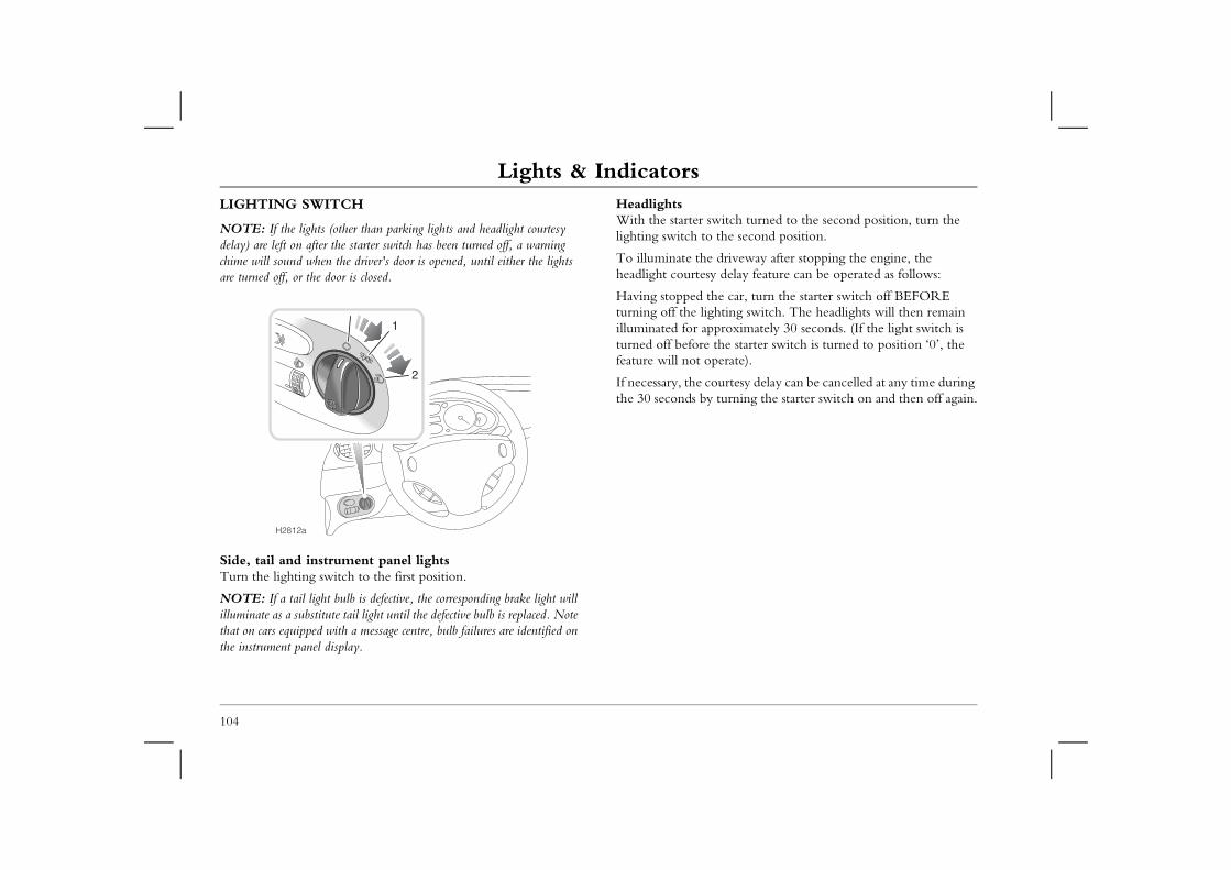
Lights & IndicatorsLights & IndicatorsLIGHTING SWITCH
NOTE: If the lights (other than parking lights and headlight courtesy
HeadlightsWith the starter switch turned to the second position, turn the lighting switch to the second position.
driveway after stopping the engine, the delay feature can be operated as follows:
e car, turn the starter switch off BEFORE hting switch. The headlights will then remain proximately 30 seconds. (If the light switch is the starter switch is turned to position ‘0’, the erate).
urtesy delay can be cancelled at any time during turning the starter switch on and then off again.
104
delay) are left on after the starter switch has been turned off, a warning chime will sound when the driver's door is opened, until either the lights are turned off, or the door is closed.
Side, tail and instrument panel lightsTurn the lighting switch to the first position.
NOTE: If a tail light bulb is defective, the corresponding brake light will illuminate as a substitute tail light until the defective bulb is replaced. Note that on cars equipped with a message centre, bulb failures are identified on the instrument panel display.
To illuminate theheadlight courtesy
Having stopped thturning off the ligilluminated for apturned off before feature will not op
If necessary, the cothe 30 seconds by
H2812a
1
2
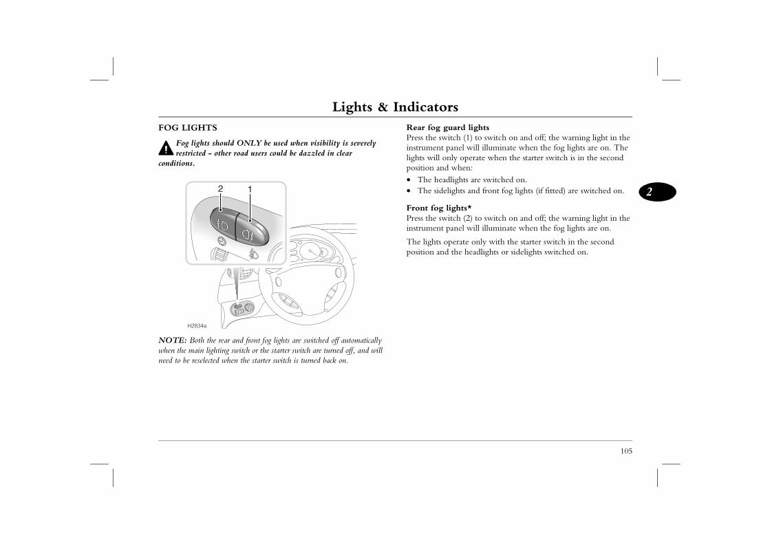
Lights & Indicators
105
2
uard lightsitch (1) to switch on and off; the warning light in the panel will illuminate when the fog lights are on. The nly operate when the starter switch is in the second when:
dlights are switched on.lights and front fog lights (if fitted) are switched on.
lights*itch (2) to switch on and off; the warning light in the panel will illuminate when the fog lights are on.
perate only with the starter switch in the second the headlights or sidelights switched on.
FOG LIGHTS
Fog lights should ONLY be used when visibility is severely restricted - other road users could be dazzled in clear
conditions.
NOTE: Both the rear and front fog lights are switched off automatically when the main lighting switch or the starter switch are turned off, and will need to be reselected when the starter switch is turned back on.
Rear fog gPress the swinstrument lights will oposition and• The hea• The side
Front fog Press the swinstrument
The lights oposition and
H2834a
12
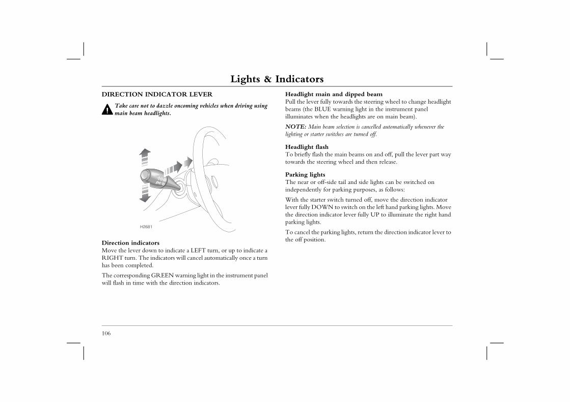
Lights & IndicatorsDIRECTION INDICATOR LEVER
Take care not to dazzle oncoming vehicles when driving using
Headlight main and dipped beamPull the lever fully towards the steering wheel to change headlight beams (the BLUE warning light in the instrument panel
the headlights are on main beam).
m selection is cancelled automatically whenever the itches are turned off.
e main beams on and off, pull the lever part way ng wheel and then release.
de tail and side lights can be switched on parking purposes, as follows:
itch turned off, move the direction indicator to switch on the left hand parking lights. Move ator lever fully UP to illuminate the right hand
ing lights, return the direction indicator lever to
106
main beam headlights.
Direction indicatorsMove the lever down to indicate a LEFT turn, or up to indicate a RIGHT turn. The indicators will cancel automatically once a turn has been completed.
The corresponding GREEN warning light in the instrument panel will flash in time with the direction indicators.
illuminates when
NOTE: Main bealighting or starter sw
Headlight flashTo briefly flash thtowards the steeri
Parking lightsThe near or off-siindependently for
With the starter swlever fully DOWNthe direction indicparking lights.
To cancel the parkthe off position.
H2681
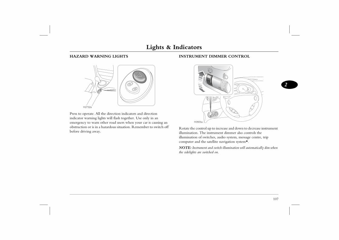
Lights & Indicators
107
2
ENT DIMMER CONTROL
ontrol up to increase and down to decrease instrument . The instrument dimmer also controls the of switches, audio system, message centre, trip d the satellite navigation system*.
trument and switch illumination will automatically dim when are switched on.
805a
HAZARD WARNING LIGHTS
Press to operate. All the direction indicators and direction indicator warning lights will flash together. Use only in an emergency to warn other road users when your car is causing an obstruction or is in a hazardous situation. Remember to switch off before driving away.
INSTRUM
Rotate the cilluminationilluminationcomputer an
NOTE: Insthe sidelights
H2732a
H2
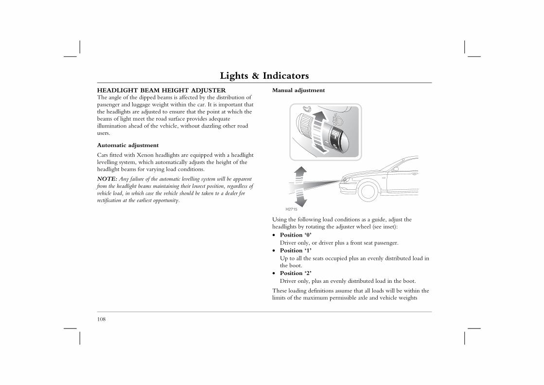
Lights & IndicatorsHEADLIGHT BEAM HEIGHT ADJUSTERThe angle of the dipped beams is affected by the distribution of passenger and luggage weight within the car. It is important that
Manual adjustment
g load conditions as a guide, adjust the ting the adjuster wheel (see inset):
r driver plus a front seat passenger.
ats occupied plus an evenly distributed load in
us an evenly distributed load in the boot.
initions assume that all loads will be within the mum permissible axle and vehicle weights
108
the headlights are adjusted to ensure that the point at which the beams of light meet the road surface provides adequate illumination ahead of the vehicle, without dazzling other road users.
Automatic adjustment
Cars fitted with Xenon headlights are equipped with a headlight levelling system, which automatically adjusts the height of the headlight beams for varying load conditions.
NOTE: Any failure of the automatic levelling system will be apparent from the headlight beams maintaining their lowest position, regardless of vehicle load, in which case the vehicle should be taken to a dealer for rectification at the earliest opportunity.
Using the followinheadlights by rota• Position ‘0’
Driver only, o• Position ‘1’
Up to all the sethe boot.
• Position ‘2’Driver only, pl
These loading deflimits of the maxi
H2715
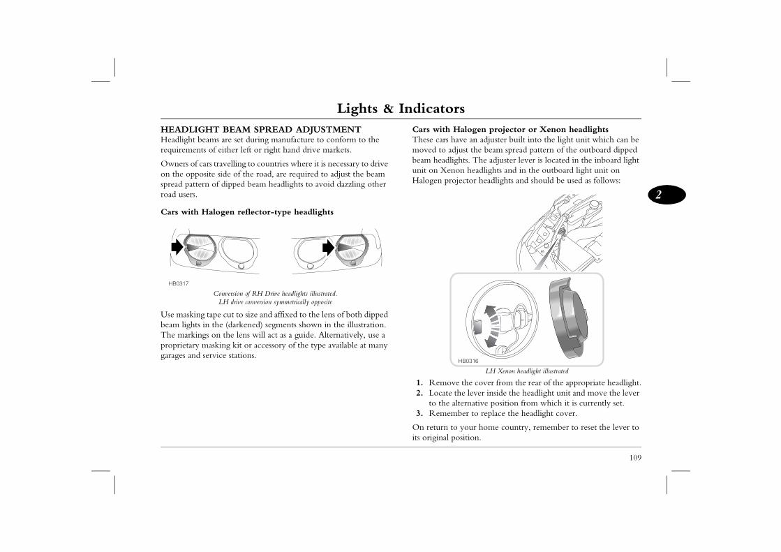
Lights & Indicators
109
2
Halogen projector or Xenon headlightsave an adjuster built into the light unit which can be just the beam spread pattern of the outboard dipped ghts. The adjuster lever is located in the inboard light on headlights and in the outboard light unit on jector headlights and should be used as follows:
LH Xenon headlight illustrated
e the cover from the rear of the appropriate headlight. the lever inside the headlight unit and move the lever lternative position from which it is currently set.ber to replace the headlight cover.
o your home country, remember to reset the lever to osition.
HB0316
HEADLIGHT BEAM SPREAD ADJUSTMENTHeadlight beams are set during manufacture to conform to the requirements of either left or right hand drive markets.
Owners of cars travelling to countries where it is necessary to drive on the opposite side of the road, are required to adjust the beam spread pattern of dipped beam headlights to avoid dazzling other road users.
Cars with Halogen reflector-type headlights
Conversion of RH Drive headlights illustrated. LH drive conversion symmetrically opposite
Use masking tape cut to size and affixed to the lens of both dipped beam lights in the (darkened) segments shown in the illustration. The markings on the lens will act as a guide. Alternatively, use a proprietary masking kit or accessory of the type available at many garages and service stations.
Cars with These cars hmoved to adbeam headliunit on XenHalogen pro
1. Remov2. Locate
to the a3. Remem
On return tits original p
HB0317
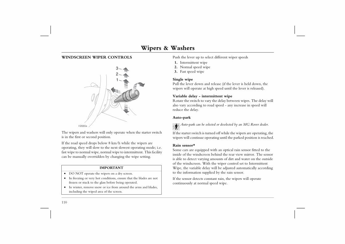
Wipers & WashersWipers & WashersWINDSCREEN WIPER CONTROLS Push the lever up to select different wiper speeds
1. Intermittent wiped wipepe
n and release (if the lever is held down, the e at high speed until the lever is released).
intermittent wipe to vary the delay between wipes. The delay will g to road speed - any increase in speed will
be selected or deselected by an MG Rover dealer.
is turned off while the wipers are operating, the ue operating until the parked position is reached.
ipped with an optical rain sensor fitted to the screen behind the rear view mirror. The sensor rying amounts of dirt and water on the outside . With the wiper control set to Intermittent delay will be adjusted automatically according supplied by the rain sensor.
ts constant rain, the wipers will operate rmal speed wipe.
110
The wipers and washers will only operate when the starter switch is in the first or second position.
If the road speed drops below 8 km/h while the wipers are operating, they will slow to the next slowest operating mode; i.e. fast wipe to normal wipe, normal wipe to intermittent. This facility can be manually overridden by changing the wipe setting.
2. Normal spee3. Fast speed wi
Single wipePull the lever dowwipers will operat
Variable delay -Rotate the switchalso vary accordinreduce the delay.
Auto-park
Auto-park can
If the starter switchwipers will contin
Rain sensor*Some cars are equinside of the windis able to detect vaof the windscreenWipe, the variableto the information
If the sensor deteccontinuously at no
IMPORTANT
• DO NOT operate the wipers on a dry screen.• In freezing or very hot conditions, ensure that the blades are not
frozen or stuck to the glass before being operated.• In winter, remove snow or ice from around the arms and blades,
including the wiped area of the screen.
H2680a
123
Wipers & Washers
111
2
REEN WIPER AND WASHER (Tourer ly)
the switch clockwise to the first position: after three ipes the wiper continues operating intermittently.
the switch further clockwise, to the second position ld against spring pressure: both wiper and washer continuously while the switch is held in this position.
washing ceases as soon as the switch is released but ittent wiping continues until the switch is returned to position.g the switch anti-clockwise to the third position s the same features described in 2 (above).
everse gear is selected while the windscreen wipers are switched te wiper will operate automatically for three wipes.
HB0020
2
1
3
WINDSCREEN WASHERSPull the lever towards the steering wheel - the washers operate immediately. After a short delay, the wipers will commence operating in conjunction with the washers, both functions continuing until the lever is released.
Note that the wipers continue operating for a further three wipes after the lever is released.
The number of wipes can be adjusted to either 2 or 4 by an MG Rover dealer.
If the washers fail to deliver the screen wash solution (dirt or ice may have blocked the jets), release the lever immediately. This will prevent the wipers from operating, and the consequent risk of visibility being impaired by dirt smearing across the unwashed windscreen.
HEADLIGHT WASHERS*When the headlights are illuminated, the headlight washers operate automatically in conjunction with every fifth operation of the windscreen washers.
REAR SCmodels on
1. Rotateinitial w
2. Rotateand hooperateScreenintermthe off
3. Rotatinprovide
NOTE: If ron, the tailga
Cruise ControlCruise ControlCRUISE CONTROL* • On petrol engine vehicles, DO NOT rest your foot under the
accelerator pedal while cruise control is engaged - your foot could become trapped.
tch off the master switch when you no longer ruise control.
se controll system has three switches; a master switch on and two control switches marked ‘SET+’ and n the steering wheel.ter switch (the switch indicator light and the in the instrument panel illuminate whenever l is operating). til the desired cruising speed is reached. This e the system's minimum operational speed of below the maximum operating speed of
set speed held in the cruise control memory will be either the cruise control master switch or the starter off.
+’ switch to set the road speed in the system ise control will now maintain that speed eed to use the accelerator pedal.
ol operating, speed can be increased by normal tor; e.g. for overtaking. When the accelerator is d will return to the selected cruising speed. On cruise control will be disengaged if the for longer than 30 seconds - lift the ‘RES’ e.
112
Cruise control enables the driver to maintain a constant road speed without using the accelerator pedal. This is particularly useful for motorway cruising, or for any journey where a constant speed can be maintained for a lengthy period.
NOTE: Using ‘sport’ mode on automatic gearbox vehicles is not recommended with cruise control selected.
The following precautions must be observed when using cruise control:• DO NOT attempt to use cruise control when using reverse
gear.• DO NOT use cruise control on winding or slippery road
surfaces, or in traffic conditions where a constant speed cannot easily be maintained.
• ALWAYS swiintend to use c
To operate cruiThe cruise controthe centre console‘RES’ mounted o1. Press the mas
warning lightcruise contro
2. Accelerate unmust be abov35 km/h and200 km/h.
NOTE: The cancelled whenswitch is turned
3. Lift the ‘SETmemory. Cruwithout the n
With cruise contruse of the accelerareleased, road speediesel engine cars,accelerator is usedswitch to re-engag
H2808b
Cruise Control
113
2
To increase the set cruising speedLift and hold the ‘SET+’ switch - the car will accelerate automatically. Release the switch as soon as the desired speed has been reached.
Alternatively, the set speed can be increased incrementally by ‘tapping’ the ‘SET+’ switch. Each operation of the switch will increase the speed by approximately 1.5 km/h.
Disengaging cruise controlCruise control will automatically disengage if the brake or clutch pedals are depressed, or if ‘N’ (neutral) is selected on an automatic gearbox. Cruise control can also be disengaged by operating the ‘RES’ switch.
To re-engage cruise control at the previously set speed, operate the ‘RES’ switch.
BrakesBrakesFOOT BRAKEFor added safety, the hydraulic braking system operates through dual circuits. If one circuit should fail, the other will continue to
Electronic brake force distributionYour car is equipped with Electronic Brake force Distribution (EBD), which, in order to maintain braking efficiency,
ortions the distribution of braking forces rear axles, under all load conditions.
er light loads EBD applies less effort to the rear maintain vehicle stability; however if the car is wing, then more effort will be applied to the
incorporates a monitoring system, which checks omponents are in working order when the rned on and also at frequent intervals while the . The EBD monitoring system is linked to the ing light on the instrument panel. If this light
driving, or remains illuminated for more than r the starter switch is turned on, there is a fault ystem, and EBD may not be available. If this r as soon as safety permits and seek qualified
ately. DO NOT drive the car with the brake ht illuminated.
ater or even very heavy rain may adversely iency. Dry the braking surfaces by intermittent f the foot brake, after first ensuring that you are rom other road users.
114
function, but increased brake pedal travel, greater pedal pressure, and longer stopping distances will be experienced.
In the event of a brake failure where only one circuit is operational, the car should be brought to a halt as soon as traffic conditions safely allow. DO NOT continue driving - seek qualified assistance.
Servo assistanceThe braking system is servo assisted, but ONLY while the engine is running. Without servo assistance greater brake pedal effort is necessary to safely control the car, resulting in longer stopping distances. Always be aware of the following:• NEVER allow the car to freewheel with the engine turned off.• ALWAYS take particular care when being towed with the
engine turned off.
If the engine should stop for any reason while driving, bring the car to a halt as quickly as traffic conditions safely allow, and DO NOT pump the brake pedal lest the braking system lose any remaining servo-assistance available.
NEVER move the car without the engine running because brake servo assistance may not be available. The brakes will
still function, but more pedal pressure will be required to operate them.
automatically propbetween front and
For example; undbrakes in order toheavily laden or torear brakes.
The EBD system that all electrical cstarter switch is tucar is being drivenbrake system warnilluminates while three seconds aftewith the braking soccurs, stop the caassistance immedisystem warning lig
Wet conditionsDriving through waffect braking efficlight application oat a safe distance f
Brakes
115
2
wear indicatorheels are fitted with brake pad wear sensors. When a ears to a predetermined point, the sensor activates the panel warning light/display. The warning will remain the worn brake pad is replaced.
Brake system warning lightThe warning light on the instrument panel should illuminate for about 3 seconds as a bulb check whenever
the starter switch is turned to the second position, and also illuminate whenever the handbrake is applied (provided the starter is switched to the second position).
If the warning light illuminates while driving, or fails to extinguish when the handbrake is fully released, a fault with the braking system is indicated. Check the brake fluid level; if the light continues to illuminate, seek qualified assistance before continuing.
If the brake warning light illuminates while driving, bring the car to a halt as quickly as traffic conditions and safety permit
and seek qualified assistance before continuing. DO NOT drive with the warning light illuminated.
Brake padsBrake pads require a period of bedding in. For the first 800 km, you should avoid situations where heavy braking is required.
Remember that regular servicing is vital to ensure that all the brake components are examined for wear at the correct intervals, and changed when required to ensure long term safety and optimum performance.
DO NOT rest your foot on the brake pedal while driving; this may overheat the brakes, reduce their efficiency and cause
excessive wear.
Brake padThe road wbrake pad winstrument active until
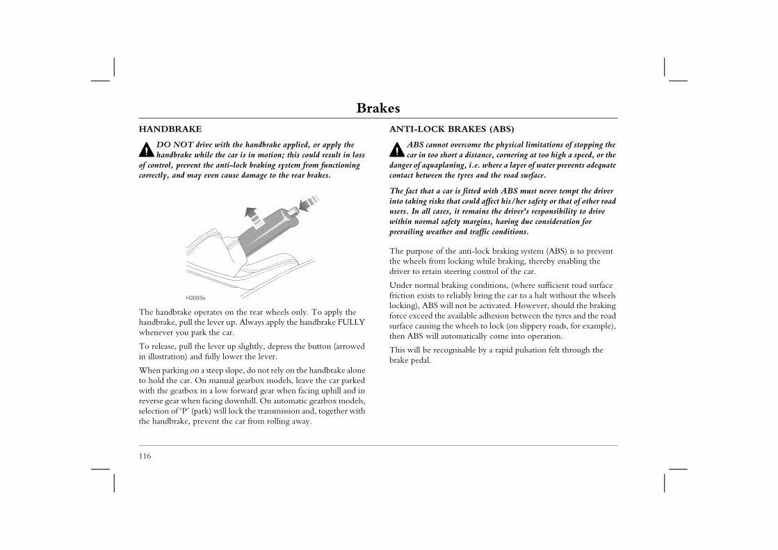
BrakesHANDBRAKE
DO NOT drive with the handbrake applied, or apply the
ANTI-LOCK BRAKES (ABS)
ABS cannot overcome the physical limitations of stopping the rt a distance, cornering at too high a speed, or the ing, i.e. where a layer of water prevents adequate e tyres and the road surface.
is fitted with ABS must never tempt the driver at could affect his/her safety or that of other road it remains the driver's responsibility to drive ety margins, having due consideration for and traffic conditions.
e anti-lock braking system (ABS) is to prevent cking while braking, thereby enabling the ering control of the car.
king conditions, (where sufficient road surface liably bring the car to a halt without the wheels l not be activated. However, should the braking vailable adhesion between the tyres and the road wheels to lock (on slippery roads, for example), omatically come into operation.
nisable by a rapid pulsation felt through the
116
handbrake while the car is in motion; this could result in loss of control, prevent the anti-lock braking system from functioning correctly, and may even cause damage to the rear brakes.
The handbrake operates on the rear wheels only. To apply the handbrake, pull the lever up. Always apply the handbrake FULLY whenever you park the car.
To release, pull the lever up slightly, depress the button (arrowed in illustration) and fully lower the lever.
When parking on a steep slope, do not rely on the handbrake alone to hold the car. On manual gearbox models, leave the car parked with the gearbox in a low forward gear when facing uphill and in reverse gear when facing downhill. On automatic gearbox models, selection of ‘P’ (park) will lock the transmission and, together with the handbrake, prevent the car from rolling away.
car in too shodanger of aquaplancontact between th
The fact that a carinto taking risks thusers. In all cases,within normal safprevailing weather
The purpose of ththe wheels from lodriver to retain ste
Under normal brafriction exists to relocking), ABS wilforce exceed the asurface causing thethen ABS will aut
This will be recogbrake pedal.
H2693a
Brakes
117
2
ing light he ABS incorporates a monitoring system, which ecks that all the electrical components are in working
n as the starter switch is turned on, and also at frequent ring a journey.
g light on the instrument panel is an important part of The light should illuminate for approximately 2 en the starter switch is turned to the second position tinguish.
ng light fails to extinguish or illuminates while driving, een detected by the self-monitoring system and full l may not be available. If this occurs, consult your earliest opportunity.
e normal (non-ABS) braking system remains fully operational ected by partial or full loss of the ABS. However, braking increase.
Braking in an emergency
DO NOT pump the brake pedal at any time; this will interrupt operation of the ABS and may increase braking
distance.
If an emergency situation occurs, the driver should apply full braking effort even when the road surface is slippery. The anti-lock braking system will constantly monitor the rotational speed of the wheels and vary braking pressure to each according to the amount of traction available. This will ensure that the wheels do not lock and that the car is brought to a halt in the shortest possible distance for the prevailing road surface conditions.
NOTE: On soft surfaces such as powdery snow, sand or gravel, the braking distance required by the anti-lock braking system may be greater than for non-ABS braking, even though improved steering would be experienced. This is because the natural action of locked wheels on soft surfaces is to build up a wedge of surface material in front which assists the car to stop.
No matter how hard you brake, you should be able to continue steering the vehicle as NORMAL.
However, always remember that anti-lock braking operates only AFTER the driver has already lost control. ABS cannot reliably compensate for driver error or inexperience.
ABS WarnTch
order as soointervals du
The warninthis system. seconds whand then ex
If the warnia fault has bABS controdealer at the
NOTE: Thand is not affdistances may
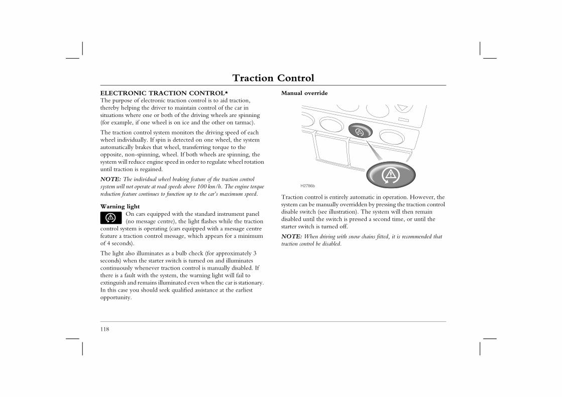
Traction ControlTraction ControlELECTRONIC TRACTION CONTROL*The purpose of electronic traction control is to aid traction, thereby helping the driver to maintain control of the car in
Manual override
s entirely automatic in operation. However, the ually overridden by pressing the traction control illustration). The system will then remain switch is pressed a second time, or until the rned off.
ving with snow chains fitted, it is recommended that sabled.
118
situations where one or both of the driving wheels are spinning (for example, if one wheel is on ice and the other on tarmac).
The traction control system monitors the driving speed of each wheel individually. If spin is detected on one wheel, the system automatically brakes that wheel, transferring torque to the opposite, non-spinning, wheel. If both wheels are spinning, the system will reduce engine speed in order to regulate wheel rotation until traction is regained.
NOTE: The individual wheel braking feature of the traction control system will not operate at road speeds above 100 km/h. The engine torque reduction feature continues to function up to the car’s maximum speed.
Warning lightOn cars equipped with the standard instrument panel (no message centre), the light flashes while the traction
control system is operating (cars equipped with a message centre feature a traction control message, which appears for a minimum of 4 seconds).
The light also illuminates as a bulb check (for approximately 3 seconds) when the starter switch is turned on and illuminates continuously whenever traction control is manually disabled. If there is a fault with the system, the warning light will fail to extinguish and remains illuminated even when the car is stationary. In this case you should seek qualified assistance at the earliest opportunity.
Traction control isystem can be mandisable switch (seedisabled until the starter switch is tu
NOTE: When dritraction control be di
H2786b
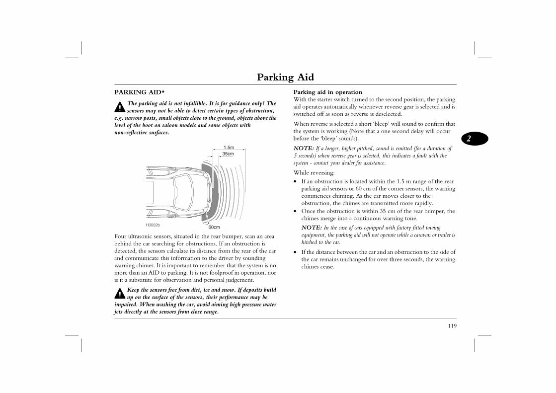
Parking Aid
119
2
Parking Aid d in operationrter switch turned to the second position, the parking automatically whenever reverse gear is selected and is f as soon as reverse is deselected.
se is selected a short ‘bleep’ will sound to confirm that s working (Note that a one second delay will occur bleep’ sounds).
longer, higher pitched, sound is emitted (for a duration of en reverse gear is selected, this indicates a fault with the
act your dealer for assistance.
sing:truction is located within the 1.5 m range of the rear id sensors or 60 cm of the corner sensors, the warning ces chiming. As the car moves closer to the on, the chimes are transmitted more rapidly. e obstruction is within 35 cm of the rear bumper, the erge into a continuous warning tone.
In the case of cars equipped with factory fitted towing t, the parking aid will not operate while a caravan or trailer is the car.
tance between the car and an obstruction to the side of mains unchanged for over three seconds, the warning ease.
PARKING AID*
The parking aid is not infallible. It is for guidance only! The sensors may not be able to detect certain types of obstruction,
e.g. narrow posts, small objects close to the ground, objects above the level of the boot on saloon models and some objects with non-reflective surfaces.
Four ultrasonic sensors, situated in the rear bumper, scan an area behind the car searching for obstructions. If an obstruction is detected, the sensors calculate its distance from the rear of the car and communicate this information to the driver by sounding warning chimes. It is important to remember that the system is no more than an AID to parking. It is not foolproof in operation, nor is it a substitute for observation and personal judgement.
Keep the sensors free from dirt, ice and snow. If deposits build up on the surface of the sensors, their performance may be
impaired. When washing the car, avoid aiming high pressure water jets directly at the sensors from close range.
Parking aiWith the staaid operatesswitched of
When reverthe system ibefore the ‘
NOTE: If a5 seconds) whsystem - cont
While rever• If an obs
parking acommenobstructi
• Once thchimes m
NOTE:equipmenhitched to
• If the disthe car rechimes c
35cm
60cm
1.5m
H3002b

3
3
Audio System
122 Audio System Identification123 Radio Reception124 Radio Data System125 Remote Audio Controls126 CD32 - Audio System141 Harmony - Audio System150 Symphony - Audio System162 CD Changer Unit164 Care of Cassette Player and Tapes165 Satellite Navigation178 Satellite Navigation System Settings180 Security Code
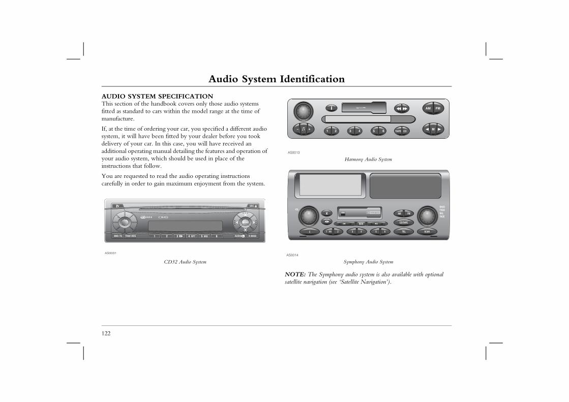
Audio System IdentificationAudio SystemAudio System IdentificationAUDIO SYSTEM SPECIFICATIONThis section of the handbook covers only those audio systems
Harmony Audio System
Symphony Audio System
hony audio system is also available with optional see ‘Satellite Navigation’).
122
fitted as standard to cars within the model range at the time of manufacture.
If, at the time of ordering your car, you specified a different audio system, it will have been fitted by your dealer before you took delivery of your car. In this case, you will have received an additional operating manual detailing the features and operation of your audio system, which should be used in place of the instructions that follow.
You are requested to read the audio operating instructions carefully in order to gain maximum enjoyment from the system.
CD32 Audio System
NOTE: The Sympsatellite navigation (
AS0031
AS0013
AS0014
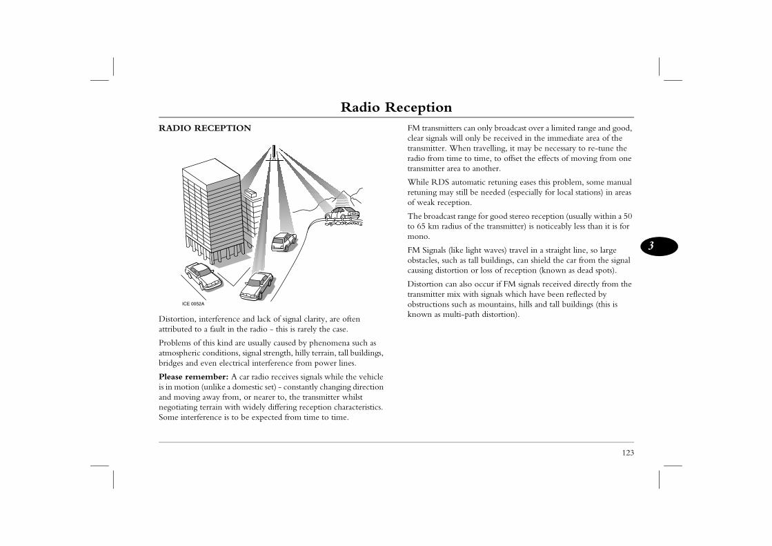
Radio Reception
123
3
Radio Reception tters can only broadcast over a limited range and good, will only be received in the immediate area of the When travelling, it may be necessary to re-tune the ime to time, to offset the effects of moving from one area to another.
automatic retuning eases this problem, some manual y still be needed (especially for local stations) in areas eption.
ast range for good stereo reception (usually within a 50 dius of the transmitter) is noticeably less than it is for
(like light waves) travel in a straight line, so large ch as tall buildings, can shield the car from the signal ortion or loss of reception (known as dead spots).
an also occur if FM signals received directly from the mix with signals which have been reflected by such as mountains, hills and tall buildings (this is ulti-path distortion).
RADIO RECEPTION
Distortion, interference and lack of signal clarity, are often attributed to a fault in the radio - this is rarely the case.
Problems of this kind are usually caused by phenomena such as atmospheric conditions, signal strength, hilly terrain, tall buildings, bridges and even electrical interference from power lines.
Please remember: A car radio receives signals while the vehicle is in motion (unlike a domestic set) - constantly changing direction and moving away from, or nearer to, the transmitter whilst negotiating terrain with widely differing reception characteristics. Some interference is to be expected from time to time.
FM transmiclear signalstransmitter.radio from ttransmitter
While RDSretuning maof weak rec
The broadcto 65 km ramono.
FM Signals obstacles, sucausing dist
Distortion ctransmitter obstructionsknown as m
ICE 0052A
Radio Data SystemRadio Data SystemRADIO DATA SYSTEM (RDS)Your radio is equipped with RDS (Radio Data System). RDS is being introduced in European countries and operates on the FM
Receiving RDS stationsHarmony and Symphony audio units are automatically in the RDS mode whenever the FM waveband is selected. On the CD32
ctable (see ‘RADIO CONTROLS’, page 130).
whenever an RDS radio station is received, the inates in the display. The audio constantly scans uencies on which that station can be received, switches to the strongest available signal.
useful on long journeys where the car travels transmitter areas serving the same radio station.
ony and Symphony audio units this facility can be ated by your dealer.
regional broadcastst local radio stations is intentionally limited to a ll area around the transmitter.
the reception range is reached, it is unlikely that ill be able to locate an alternative frequency for ion being received.
countries, certain broadcasting companies rogrammes on the FM waveband, either riodically during the day. This may result in the g between a number of different regional radio radio programme you have selected.
ony and Symphony audio units, this facility can only ctivated by your dealer. On the CD32 audio, the see ‘REG ON’ and ‘REG OFF’ in ‘MENU CTIONS’, page 140).
124
waveband. The system enables the audio unit to receive other information in addition to radio signals. Depending upon the specification of the audio unit fitted to your car, these may include:• the programme service name: enables the set to display the radio
station name instead of the frequency.• alternative frequencies for the FM radio station being received: enables
the audio unit to automatically select the strongest available signal, thereby maintaining the best possible reception.
• a traffic and/or news information facility: enables the audio unit to give priority to traffic and/or news information broadcasts over other radio, tape or CD programmes.
• an alarm announcement facility: enables the set to give priority to emergency information broadcasts; e.g.very serious accidents or natural disasters.
• EON (enhanced other networks): enables the audio unit to broadcast traffic and/or news information from radio stations other than the one to which the radio is currently tuned (provided they are all members of a linked network).
• PTY (programme type): enables the audio unit to be programmed to select broadcasts of a specific programme type.
NOTE: In some countries, not all FM radio stations broadcast RDS. If a non-RDS station is received, these features will not be available.
audio RDS is sele
With RDS active,station name illumall alternative freqand automatically
This is particularlythrough different
NOTE: On Harmdeactivated or reactiv
Local radio andReception of moscomparatively sma
Once the limit of the RDS facility wthe local radio stat
Note that in sometransmit regional pcontinuously or peaudio unit changinstations within the
NOTE: On Harmbe deactivated or reafeature is selectable (CONTROL FUN
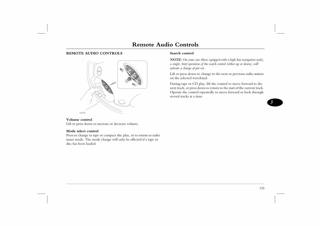
Remote Audio Controls
125
3
Remote Audio Controls trol
some cars (those equipped with a high-line navigation unit), operation of the search control (either up or down), will nge of pre-set.
down to change to the next or previous radio station ted waveband.
or CD play, lift the control to move forward to the r press down to return to the start of the current track. control repeatedly to move forward or back through s at a time.
REMOTE AUDIO CONTROLS
Volume controlLift or press down to increase or decrease volume.
Mode select controlPress to change to tape or compact disc play, or to return to radio tuner mode. The mode change will only be effected if a tape or disc has been loaded.
Search con
NOTE: Ona single, briefactivate a cha
Lift or presson the selec
During tapenext track, oOperate theseveral track
H2724
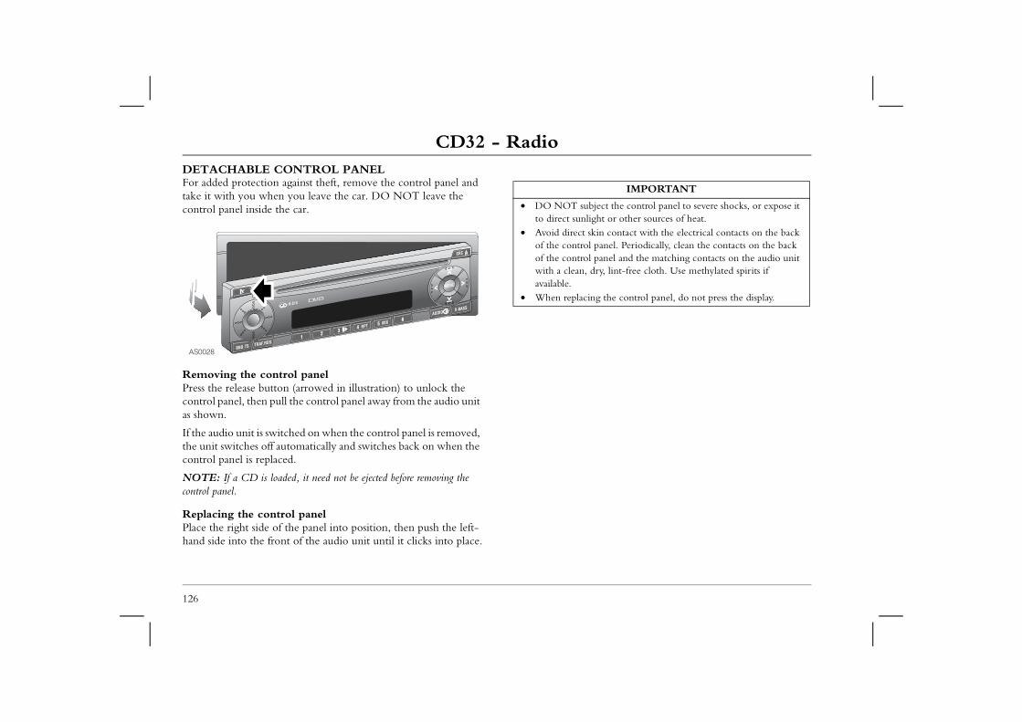
CD32 - RadioCD32 - RadioDETACHABLE CONTROL PANELFor added protection against theft, remove the control panel and take it with you when you leave the car. DO NOT leave the
IMPORTANT
ject the control panel to severe shocks, or expose it ht or other sources of heat. in contact with the electrical contacts on the back panel. Periodically, clean the contacts on the back panel and the matching contacts on the audio unit ry, lint-free cloth. Use methylated spirits if
g the control panel, do not press the display.
126
control panel inside the car.
Removing the control panelPress the release button (arrowed in illustration) to unlock the control panel, then pull the control panel away from the audio unit as shown.
If the audio unit is switched on when the control panel is removed, the unit switches off automatically and switches back on when the control panel is replaced.
NOTE: If a CD is loaded, it need not be ejected before removing the control panel.
Replacing the control panelPlace the right side of the panel into position, then push the left-hand side into the front of the audio unit until it clicks into place.
AS0028
• DO NOT subto direct sunlig
• Avoid direct skof the control of the control with a clean, davailable.
• When replacin
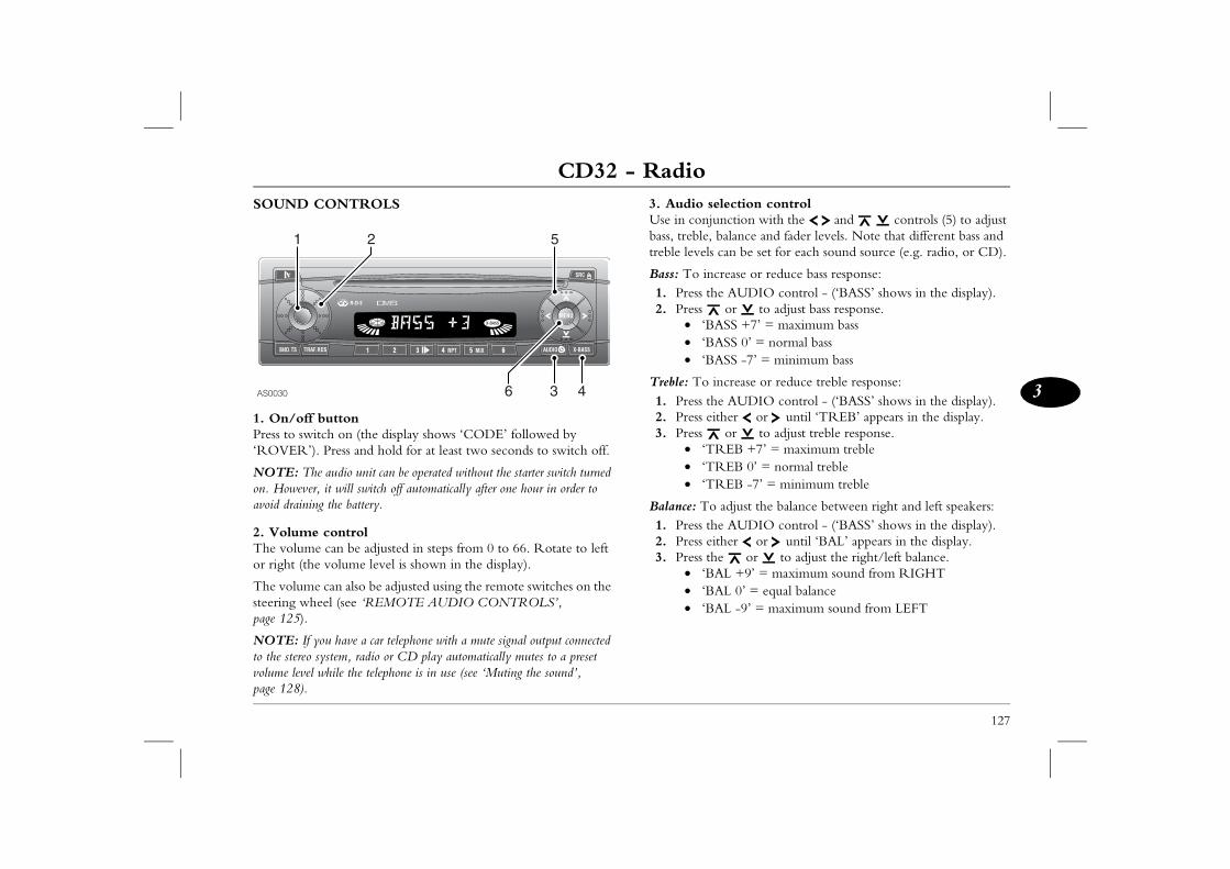
CD32 - Radio
127
3
election controlunction with the and controls (5) to adjust balance and fader levels. Note that different bass and can be set for each sound source (e.g. radio, or CD).
crease or reduce bass response:e AUDIO control - (‘BASS’ shows in the display). or to adjust bass response.
ASS +7’ = maximum bassASS 0’ = normal bassASS -7’ = minimum bass
increase or reduce treble response:e AUDIO control - (‘BASS’ shows in the display).
ither or until ‘TREB’ appears in the display. or to adjust treble response.
REB +7’ = maximum trebleREB 0’ = normal trebleREB -7’ = minimum treble
adjust the balance between right and left speakers:e AUDIO control - (‘BASS’ shows in the display).
ither or until ‘BAL’ appears in the display. e or to adjust the right/left balance.AL +9’ = maximum sound from RIGHTAL 0’ = equal balanceAL -9’ = maximum sound from LEFT
SOUND CONTROLS
1. On/off buttonPress to switch on (the display shows ‘CODE’ followed by ‘ROVER’). Press and hold for at least two seconds to switch off.
NOTE: The audio unit can be operated without the starter switch turned on. However, it will switch off automatically after one hour in order to avoid draining the battery.
2. Volume controlThe volume can be adjusted in steps from 0 to 66. Rotate to left or right (the volume level is shown in the display).
The volume can also be adjusted using the remote switches on the steering wheel (see ‘REMOTE AUDIO CONTROLS’, page 125).
NOTE: If you have a car telephone with a mute signal output connected to the stereo system, radio or CD play automatically mutes to a preset volume level while the telephone is in use (see ‘Muting the sound’, page 128).
3. Audio sUse in conjbass, treble,treble levels
Bass: To in1. Press th2. Press
• ‘B• ‘B• ‘B
Treble: To 1. Press th2. Press e3. Press
• ‘T• ‘T• ‘T
Balance: To1. Press th2. Press e3. Press th
• ‘B• ‘B• ‘B
AS0030
51 2
6 43
CD32 - RadioFader: To adjust the balance between front and rear speakers:1. Press the AUDIO control - (‘BASS’ shows in the display).
Muting the soundBriefly press the on/off button (1) (‘MUTE’ appears in the display). The volume will instantly reduce to a preset level. The
el can be adjusted as follows: NU button (6).control until ‘MUTE LVL’ is displayed. controls to adjust the volume.NU button twice to store the setting.
er-on volumee (the volume level present when the audio unit n be adjusted, as follows: NU button (6).l ‘ON VOL’ is displayed. to reduce or increase the volume.NU button twice to store the setting.
VOL’ is selected, the power-on volume will be the level that was set when the unit was last switched off, t exceed volume level 38.
128
2. Press or until ‘FADER’ appears in the display. 3. Press or to adjust the front/rear balance.
• ‘FADER +9’ = maximum sound from FRONT• ‘FADER 0’ = equal balance• ‘FADER -9’ = maximum sound from REAR
4. X-Bass controlUse the X-BASS feature to boost bass responses at low volume. Separate levels can be set for each sound source (e.g. radio, or CD).1. Press the X-Bass control.2. Repeatedly press either the or controls (5) until the
required setting is displayed.• ‘X BASSOFF = feature switched off.• ‘X BASS 1 = minimum boost.• ‘X BASS 2 = medium boost.• ‘X BASS 3 = maximum boost.
3. Press the X-Bass control to store the required setting.
NOTE: After 8 seconds without further adjustment, all audio settings are stored and the selection mode (including X-BASS) cancels automatically.
preset volume lev1. Press the ME2. Press the 3. Press the 4. Press the ME
Setting the powThe default volumis switched on) ca1. Press the ME2. Press unti3. Press or 4. Press the ME
NOTE: If ‘LASTsame as the volume provided this did no
CD32 - Radio
129
3
Output level displayIlluminated bars flash in the display to provide a graphic indication of the sound control settings as they are adjusted. At other times, the display symbolises the radio’s output level. The output level display can be enabled or disabled as follows:1. Press the MENU button (6).2. Press the control until ‘PEAK LVL’ is displayed.3. Press or to select ‘PEAK ON’ or ‘PEAK OFF’.4. Press the MENU button twice to store the setting.
Treble reduction feature (HICUT) - FM onlyHICUT improves reception in poor operating conditions. If interference occurs, the treble is automatically reduced. The feature can be enabled or disabled as follows:1. Press the MENU button (6).2. Press the control until ‘HICUT’ is displayed.3. Press the or controls to select ‘HICUT 1’ (treble
reduction activated), or ‘HICUT 0’ (no treble reduction).4. Press the MENU button to store the setting.
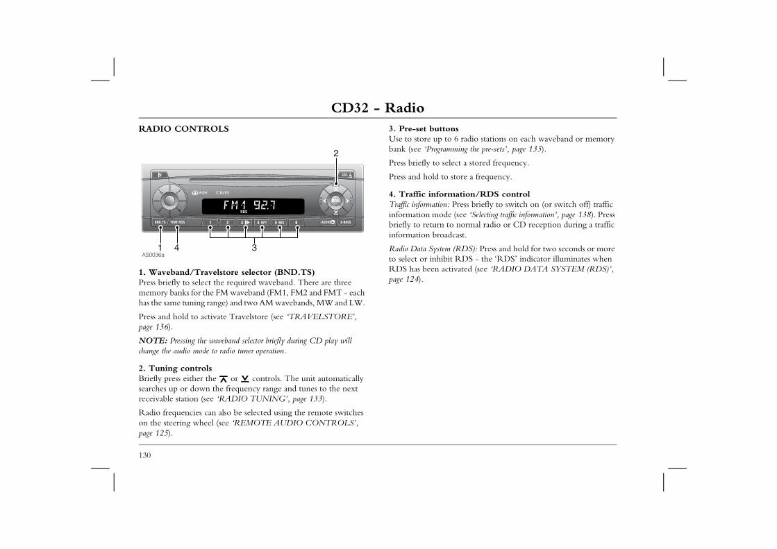
CD32 - RadioRADIO CONTROLS 3. Pre-set buttons
Use to store up to 6 radio stations on each waveband or memory bank (see ‘Programming the pre-sets’, page 135).
ect a stored frequency.
store a frequency.
ation/RDS controlPress briefly to switch on (or switch off) traffic (see ‘Selecting traffic information’, page 138). Press normal radio or CD reception during a traffic cast.
(RDS): Press and hold for two seconds or more t RDS - the ‘RDS’ indicator illuminates when ivated (see ‘RADIO DATA SYSTEM (RDS)’,
130
1. Waveband/Travelstore selector (BND.TS)Press briefly to select the required waveband. There are three memory banks for the FM waveband (FM1, FM2 and FMT - each has the same tuning range) and two AM wavebands, MW and LW.
Press and hold to activate Travelstore (see ‘TRAVELSTORE’, page 136).
NOTE: Pressing the waveband selector briefly during CD play will change the audio mode to radio tuner operation.
2. Tuning controlsBriefly press either the or controls. The unit automatically searches up or down the frequency range and tunes to the next receivable station (see ‘RADIO TUNING’, page 133).
Radio frequencies can also be selected using the remote switches on the steering wheel (see ‘REMOTE AUDIO CONTROLS’, page 125).
Press briefly to sel
Press and hold to
4. Traffic informTraffic information: information modebriefly to return toinformation broad
Radio Data Systemto select or inhibiRDS has been actpage 124).
AS0036a
2
31 4
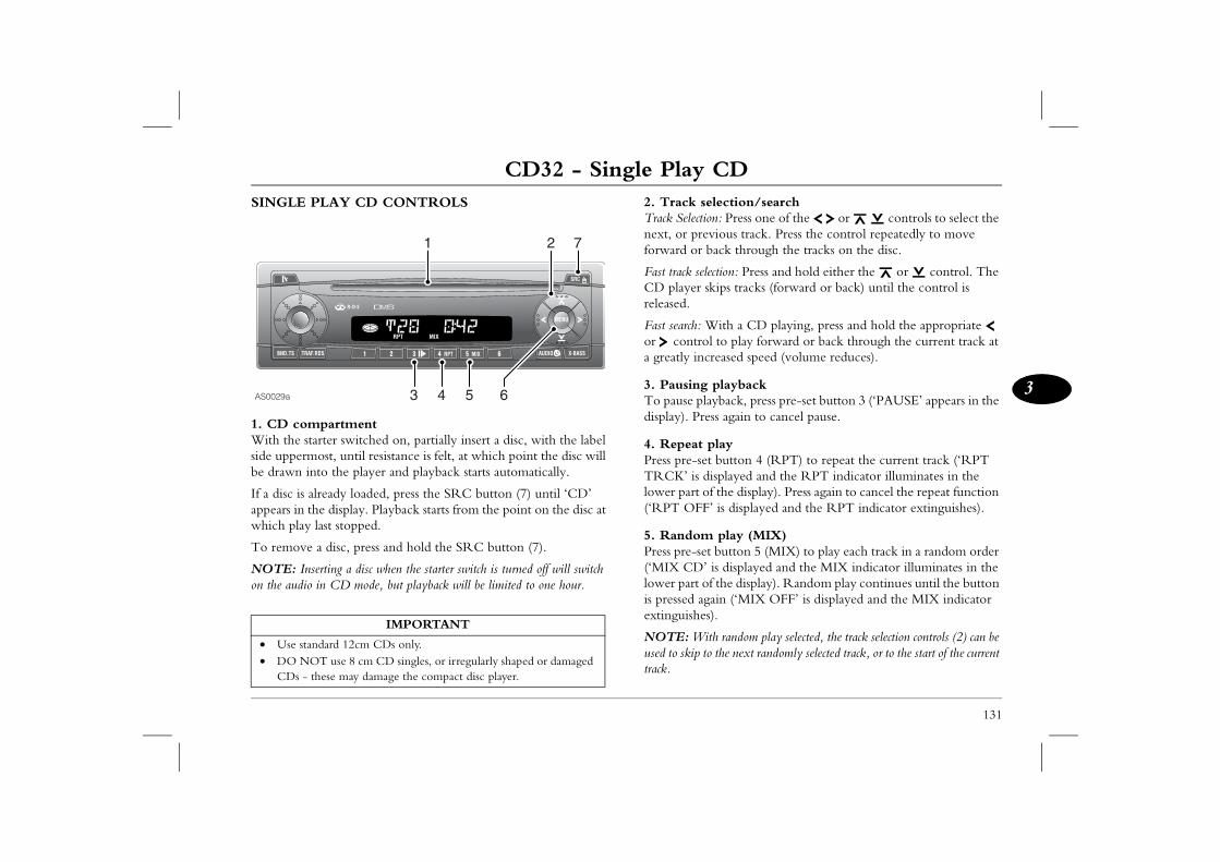
CD32 - Single Play CD
131
3
CD32 - Single Play CD lection/search n: Press one of the or controls to select the vious track. Press the control repeatedly to move ack through the tracks on the disc.
ection: Press and hold either the or control. The kips tracks (forward or back) until the control is
ith a CD playing, press and hold the appropriate l to play forward or back through the current track at reased speed (volume reduces).
playback ayback, press pre-set button 3 (‘PAUSE’ appears in the ss again to cancel pause.
playt button 4 (RPT) to repeat the current track (‘RPT isplayed and the RPT indicator illuminates in the f the display). Press again to cancel the repeat function ’ is displayed and the RPT indicator extinguishes).
play (MIX)t button 5 (MIX) to play each track in a random order is displayed and the MIX indicator illuminates in the f the display). Random play continues until the button ain (‘MIX OFF’ is displayed and the MIX indicator ).
th random play selected, the track selection controls (2) can be o the next randomly selected track, or to the start of the current
SINGLE PLAY CD CONTROLS
1. CD compartmentWith the starter switched on, partially insert a disc, with the label side uppermost, until resistance is felt, at which point the disc will be drawn into the player and playback starts automatically.
If a disc is already loaded, press the SRC button (7) until ‘CD’ appears in the display. Playback starts from the point on the disc at which play last stopped.
To remove a disc, press and hold the SRC button (7).
NOTE: Inserting a disc when the starter switch is turned off will switch on the audio in CD mode, but playback will be limited to one hour.
2. Track seTrack Selectionext, or preforward or b
Fast track selCD player sreleased.
Fast search: Wor controa greatly inc
3. PausingTo pause pldisplay). Pre
4. Repeat Press pre-seTRCK’ is dlower part o(‘RPT OFF
5. RandomPress pre-se(‘MIX CD’lower part ois pressed agextinguishes
NOTE: Wiused to skip ttrack.
IMPORTANT
• Use standard 12cm CDs only. • DO NOT use 8 cm CD singles, or irregularly shaped or damaged
CDs - these may damage the compact disc player.
AS0029a
21 7
6543
CD32 - Single Play CD6. Track scanningTrack scanning enables you to listen to the first few seconds of each track on the disc.
132
Press and hold the MENU button (6) for two seconds (‘SCAN’ appears in the display). Press the MENU button again to stop the scan at your chosen track.
NOTE: The scan time can be adjusted to suit your requirements (see ‘MENU CONTROL FUNCTIONS’, page 140).
7. CD mode selection/CD eject controlPress briefly to change to or from CD or radio modes.
With the audio unit switched on, press and hold for two seconds or more to eject a disc.
Changing the display The information appearing in the display can be set to show either: the track number (e.g ‘T18 PLAY’), or the track number and elapsed time display (e.g T12 2:39’), as follows:1. Press the MENU button (6).2. Press the control until ‘CD DISP’ is displayed.3. Press the controls alternately to select ‘PLAY’ or ‘TIME’.4. Press the MENU button twice to store your selection.
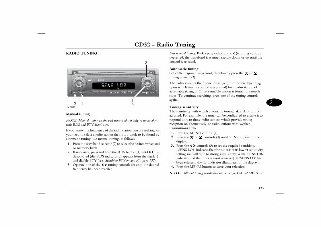
CD32 - Radio Tuning
133
3
CD32 - Radio Tuning tuning: By keeping either of the tuning controls he waveband is scanned rapidly down or up until the leased.
tuningquired waveband, then briefly press the or rol (3).
arches the frequency range (up or down depending tuning control was pressed) for a radio station of trength. Once a suitable station is found, the search ntinue searching, press one of the tuning controls
sitivityity with which automatic tuning takes place can be r example, the tuner can be configured to enable it to y to those radio stations which provide strong r, alternatively, to radio stations with weaker s as well. e MENU control (4).e or controls (3) until ‘SENS’ appears in the
.e controls (3) to set the required sensitivity LO1’ indicates that the tuner is at its lowest sensitivity and will tune to strong signals only, while ‘SENS HI6 es that the tuner is most sensitive). If ‘SENS LO’ has lected, the ‘lo’ indicator illuminates in the display.e MENU button to store your selection.
fferent tuning sensitivities can be set for FM and MW/LW.
RADIO TUNING
Manual tuning
NOTE: Manual tuning on the FM waveband can only be undertaken with RDS and PTY deactivated.
If you know the frequency of the radio station you are seeking, or you need to select a radio station that is too weak to be found by automatic tuning, use manual tuning, as follows:1. Press the waveband selector (2) to select the desired waveband
or memory bank.2. If necessary, press and hold the RDS button (1) until RDS is
deactivated (the RDS indicator disappears from the display) and disable PTY (see ‘Switching PTY on and off’, page 137).
3. Operate one of the tuning controls (3) until the desired frequency has been reached.
Fast manual depressed, tcontrol is re
AutomaticSelect the retuning cont
The radio seupon whichacceptable sstops. To coagain.
Tuning senThe sensitivadjusted. Forespond onlreception otransmission1. Press th2. Press th
display3. Press th
(‘SENSsetting indicatbeen se
4. Press th
NOTE: Di
AS0034
3
12 4
CD32 - Radio TuningWaveband scanWaveband scanning enables you to listen to all receivable stations on the selected waveband for between 5 and 30 seconds each.
134
To start scanning: Press the MENU button (4) for two seconds (‘SCAN’ is displayed briefly, followed by the frequency or station name flashing).
To stop scanning: Briefly press the MENU button again.
NOTE: The scan time can be adjusted to suit your requirements (see ‘MENU CONTROL FUNCTIONS’, page 140).
MONO/STEREOWhenever the FM waveband is selected, the radio automatically reproduces stereo sound, provided a suitable signal is available. However, if a signal becomes too weak for good stereo reception, only mono sound is produced until the signal strengthens sufficiently for stereo sound reproduction.
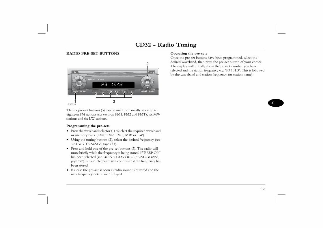
CD32 - Radio Tuning
135
3
the pre-setse-set buttons have been programmed, select the eband, then press the pre-set button of your choice. will initially show the pre-set number you have the station frequency e.g: ‘P3 101.3’. This is followed band and station frequency (or station name).
RADIO PRE-SET BUTTONS
The six pre-set buttons (3) can be used to manually store up to eighteen FM stations (six each on FM1, FM2 and FMT), six MW stations and six LW stations.
Programming the pre-sets• Press the waveband selector (1) to select the required waveband
or memory bank (FM1, FM2, FMT, MW or LW).• Using the tuning buttons (2), select the desired frequency (see
‘RADIO TUNING’, page 133).• Press and hold one of the pre-set buttons (3). The radio will
mute briefly while the frequency is being stored. If ‘BEEP ON’ has been selected (see ‘MENU CONTROL FUNCTIONS’, page 140), an audible ‘beep’ will confirm that the frequency has been stored.
• Release the pre-set as soon as radio sound is restored and the new frequency details are displayed.
OperatingOnce the prdesired wavThe displayselected andby the wave
AS0032
2
31
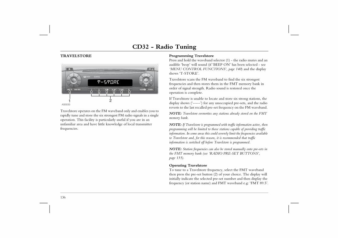
CD32 - Radio TuningTRAVELSTORE Programming Travelstore
Press and hold the waveband selector (1) - the radio mutes and an audible ‘beep’ will sound (if ‘BEEP ON’ has been selected - see
OL FUNCTIONS’, page 140) and the display ’.
the FM waveband to find the six strongest en stores them in the FMT memory bank in ngth. Radio sound is restored once the lete.
nable to locate and store six strong stations, the ---’) for any unoccupied pre-sets, and the radio ecalled pre-set frequency on the FM waveband.
e overwrites any stations already stored on the FMT
ore is programmed with traffic information active, then limited to those stations capable of providing traffic areas this could severely limit the frequencies available for this reason, it is recommended that traffic ed off before Travelstore is programmed.
quencies can also be stored manually onto pre-sets in ank (see ‘RADIO PRE-SET BUTTONS’,
elstoreelstore frequency, select the FMT waveband -set button (2) of your choice. The display will e selected pre-set number and then display the on name) and FMT waveband e.g: ‘FMT 89.5’.
136
Travelstore operates on the FM waveband only and enables you to rapidly tune and store the six strongest FM radio signals in a single operation. This facility is particularly useful if you are in an unfamiliar area and have little knowledge of local transmitter frequencies.
‘MENU CONTRshows ‘T-STORE
Travelstore scans frequencies and thorder of signal streoperation is comp
If Travelstore is udisplay shows (‘--reverts to the last r
NOTE: Travelstormemory bank.
NOTE: If Travelstprogramming will beinformation. In someto Travelstore and, information is switch
NOTE: Station frethe FMT memory bpage 135).
Operating TravTo tune to a Travthen press the preinitially indicate thfrequency (or stati
AS003321
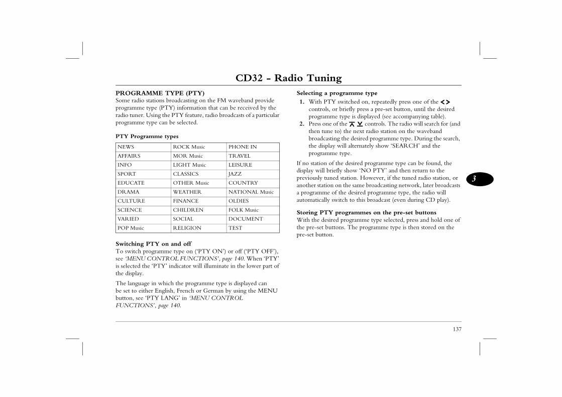
CD32 - Radio Tuning
137
3
programme typeTY switched on, repeatedly press one of the s, or briefly press a pre-set button, until the desired me type is displayed (see accompanying table).
ne of the controls. The radio will search for (and ne to) the next radio station on the waveband asting the desired programme type. During the search, lay will alternately show ‘SEARCH’ and the me type.
of the desired programme type can be found, the briefly show ‘NO PTY’ and then return to the uned station. However, if the tuned radio station, or ion on the same broadcasting network, later broadcasts e of the desired programme type, the radio will ly switch to this broadcast (even during CD play).
Y programmes on the pre-set buttonssired programme type selected, press and hold one of uttons. The programme type is then stored on the
on.
PROGRAMME TYPE (PTY)Some radio stations broadcasting on the FM waveband provide programme type (PTY) information that can be received by the radio tuner. Using the PTY feature, radio broadcasts of a particular programme type can be selected.
PTY Programme types
Switching PTY on and off To switch programme type on (‘PTY ON’) or off (‘PTY OFF’), see ‘MENU CONTROL FUNCTIONS’, page 140. When ‘PTY’ is selected the ‘PTY’ indicator will illuminate in the lower part of the display.
The language in which the programme type is displayed can be set to either English, French or German by using the MENU button, see ‘PTY LANG’ in ‘MENU CONTROL FUNCTIONS’, page 140.
Selecting a1. With P
controlprogram
2. Press othen tubroadcthe dispprogram
If no stationdisplay will previously tanother stata programmautomatical
Storing PTWith the dethe pre-set bpre-set butt
NEWS ROCK Music PHONE IN
AFFAIRS MOR Music TRAVEL
INFO LIGHT Music LEISURE
SPORT CLASSICS JAZZ
EDUCATE OTHER Music COUNTRY
DRAMA WEATHER NATIONAL Music
CULTURE FINANCE OLDIES
SCIENCE CHILDREN FOLK Music
VARIED SOCIAL DOCUMENT
POP Music RELIGION TEST
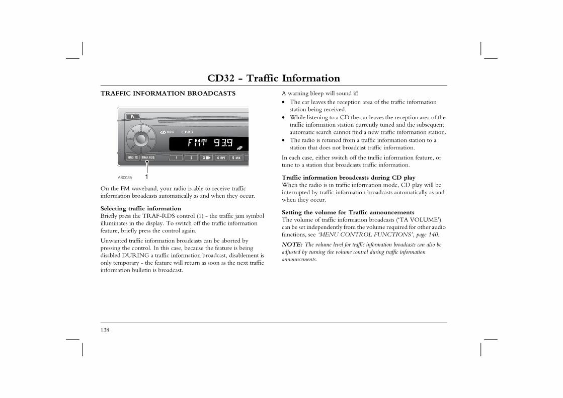
CD32 - Traffic InformationCD32 - Traffic InformationTRAFFIC INFORMATION BROADCASTS A warning bleep will sound if:
• The car leaves the reception area of the traffic information ceived. to a CD the car leaves the reception area of the ion station currently tuned and the subsequent h cannot find a new traffic information station.tuned from a traffic information station to a s not broadcast traffic information.
r switch off the traffic information feature, or hat broadcasts traffic information.
ion broadcasts during CD play in traffic information mode, CD play will be ffic information broadcasts automatically as and
me for Traffic announcementsffic information broadcasts (‘TA VOLUME’) dently from the volume required for other audio NU CONTROL FUNCTIONS’, page 140.
e level for traffic information broadcasts can also be the volume control during traffic information
138
On the FM waveband, your radio is able to receive traffic information broadcasts automatically as and when they occur.
Selecting traffic informationBriefly press the TRAF-RDS control (1) - the traffic jam symbol illuminates in the display. To switch off the traffic information feature, briefly press the control again.
Unwanted traffic information broadcasts can be aborted by pressing the control. In this case, because the feature is being disabled DURING a traffic information broadcast, disablement is only temporary - the feature will return as soon as the next traffic information bulletin is broadcast.
station being re• While listening
traffic informatautomatic searc
• The radio is restation that doe
In each case, eithetune to a station t
Traffic informatWhen the radio isinterrupted by trawhen they occur.
Setting the voluThe volume of tracan be set indepenfunctions, see ‘ME
NOTE: The volumadjusted by turning announcements.
AS0035 1
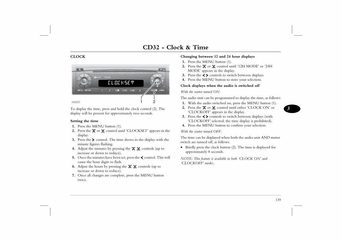
CD32 - Clock & Time
139
3
CD32 - Clock & Time between 12 and 24 hour displays e MENU button (1).e or control until ‘12H MODE’ or ‘24H ’ appears in the display.e controls to switch between displays.e MENU button to store your selection.
lays when the audio is switched off
ter turned ON:
nit can be programmed to display the time, as follows:he audio switched on, press the MENU button (1).e or control until either ‘CLOCK ON’ or KOFF’ appears in the display.e controls to switch between displays (with KOFF’ selected, the time display is prohibited).e MENU button to confirm your selection.
ter turned OFF:
n be displayed when both the audio unit AND starter urned off, as follows:ress the clock button (2). The time is displayed for ately 8 seconds.
is feature is available in both ‘CLOCK ON’ and FF’ modes.
CLOCK
To display the time, press and hold the clock control (2). The display will be present for approximately two seconds.
Setting the time1. Press the MENU button (1).2. Press the or control until ‘CLOCKSET’ appears in the
display.3. Press the control. The time shows in the display with the
minute figures flashing.4. Adjust the minutes by pressing the controls (up to
increase or down to reduce).5. Once the minutes have been set, press the control. This will
cause the hour digits to flash.6. Adjust the hours by pressing the controls (up to
increase or down to reduce).7. Once all changes are complete, press the MENU button
twice.
Changing 1. Press th2. Press th
MODE3. Press th4. Press th
Clock disp
With the star
The audio u1. With t2. Press th
‘CLOC3. Press th
‘CLOC4. Press th
With the star
The time caswitch are t• Briefly p
approxim
NOTE: Th‘CLOCKO
AS0037 1 2
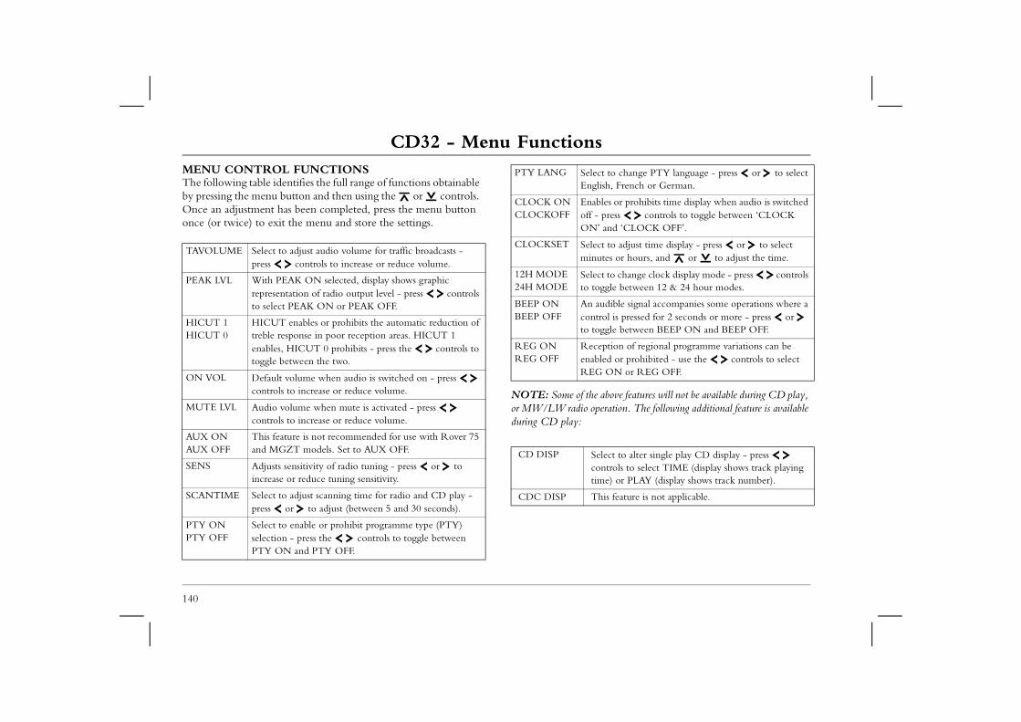
CD32 - Menu FunctionsCD32 - Menu FunctionsMENU CONTROL FUNCTIONSThe following table identifies the full range of functions obtainable by pressing the menu button and then using the or controls.
e above features will not be available during CD play, peration. The following additional feature is available
PTY LANG Select to change PTY language - press or to select English, French or German.
ables or prohibits time display when audio is switched - press controls to toggle between ‘CLOCK
’ and ‘CLOCK OFF’.
ect to adjust time display - press or to select nutes or hours, and or to adjust the time.
ect to change clock display mode - press controls toggle between 12 & 24 hour modes.
audible signal accompanies some operations where a trol is pressed for 2 seconds or more - press or
toggle between BEEP ON and BEEP OFF.
ception of regional programme variations can be bled or prohibited - use the controls to select G ON or REG OFF.
Select to alter single play CD display - press controls to select TIME (display shows track playing time) or PLAY (display shows track number).
This feature is not applicable.
140
Once an adjustment has been completed, press the menu button once (or twice) to exit the menu and store the settings.
NOTE: Some of thor MW/LW radio oduring CD play:
TAVOLUME Select to adjust audio volume for traffic broadcasts - press controls to increase or reduce volume.
PEAK LVL With PEAK ON selected, display shows graphic representation of radio output level - press controls to select PEAK ON or PEAK OFF.
HICUT 1 HICUT 0
HICUT enables or prohibits the automatic reduction of treble response in poor reception areas. HICUT 1 enables, HICUT 0 prohibits - press the controls to toggle between the two.
ON VOL Default volume when audio is switched on - press controls to increase or reduce volume.
MUTE LVL Audio volume when mute is activated - press controls to increase or reduce volume.
AUX ON AUX OFF
This feature is not recommended for use with Rover 75 and MGZT models. Set to AUX OFF.
SENS Adjusts sensitivity of radio tuning - press or to increase or reduce tuning sensitivity.
SCANTIME Select to adjust scanning time for radio and CD play - press or to adjust (between 5 and 30 seconds).
PTY ON PTY OFF
Select to enable or prohibit programme type (PTY) selection - press the controls to toggle between PTY ON and PTY OFF.
CLOCK ON CLOCKOFF
EnoffON
CLOCKSET Selmi
12H MODE 24H MODE
Selto
BEEP ON BEEP OFF
Anconto
REG ON REG OFF
ReenaRE
CD DISP
CDC DISP
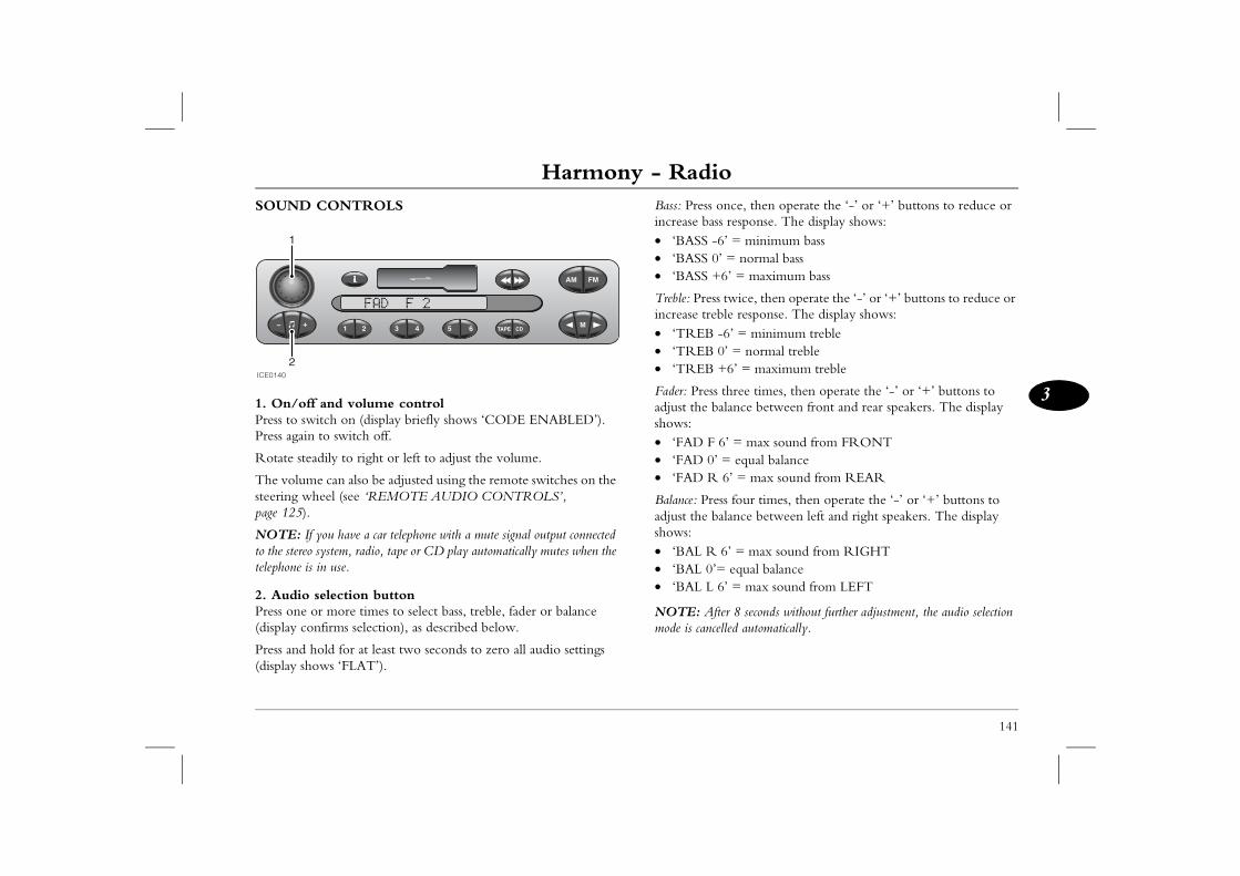
Harmony - Radio
141
3
Harmony - Radio nce, then operate the ‘-’ or ‘+’ buttons to reduce or s response. The display shows: ’ = minimum bass
’ = normal bass6’ = maximum bass
twice, then operate the ‘-’ or ‘+’ buttons to reduce or le response. The display shows:6’ = minimum treble’ = normal treble6’ = maximum treble
three times, then operate the ‘-’ or ‘+’ buttons to alance between front and rear speakers. The display
6’ = max sound from FRONT= equal balance 6’ = max sound from REAR
ss four times, then operate the ‘-’ or ‘+’ buttons to alance between left and right speakers. The display
6’ = max sound from RIGHT equal balance’ = max sound from LEFT
er 8 seconds without further adjustment, the audio selection lled automatically.
SOUND CONTROLS
1. On/off and volume controlPress to switch on (display briefly shows ‘CODE ENABLED’). Press again to switch off.
Rotate steadily to right or left to adjust the volume.
The volume can also be adjusted using the remote switches on the steering wheel (see ‘REMOTE AUDIO CONTROLS’, page 125).
NOTE: If you have a car telephone with a mute signal output connected to the stereo system, radio, tape or CD play automatically mutes when the telephone is in use.
2. Audio selection buttonPress one or more times to select bass, treble, fader or balance (display confirms selection), as described below.
Press and hold for at least two seconds to zero all audio settings (display shows ‘FLAT’).
Bass: Press oincrease bas• ‘BASS -6• ‘BASS 0• ‘BASS +
Treble: Pressincrease treb• ‘TREB -• ‘TREB 0• ‘TREB +
Fader: Pressadjust the bshows:• ‘FAD F • ‘FAD 0’ • ‘FAD R
Balance: Preadjust the bshows:• ‘BAL R • ‘BAL 0’=• ‘BAL L 6
NOTE: Aftmode is cance
ICE0140
1
2
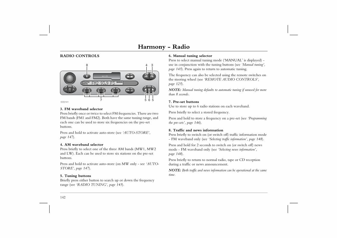
Harmony - RadioRADIO CONTROLS 6. Manual tuning selector
Press to select manual tuning mode (‘MANUAL’ is displayed) - use in conjunction with the tuning buttons (see ‘Manual tuning’,
ain to return to automatic tuning.
n also be selected using the remote switches on l (see ‘REMOTE AUDIO CONTROLS’,
ning defaults to automatic tuning if unused for more
ns 6 radio stations on each waveband.
ect a stored frequency.
store a frequency on a pre-set (see ‘Programming 46).
ews informationitch on (or switch off) traffic information mode nly (see ‘Selecting traffic information’, page 148).
2 seconds to switch on (or switch off) news band only (see ‘Selecting news information’,
urn to normal radio, tape or CD reception news announcement.
c and news information can be operational at the same
142
3. FM waveband selectorPress briefly once or twice to select FM frequencies. There are two FM bands (FM1 and FM2). Both have the same tuning range, and each one can be used to store six frequencies on the pre-set buttons.
Press and hold to activate auto-store (see ‘AUTO-STORE’, page 147).
4. AM waveband selectorPress briefly to select one of the three AM bands (MW1, MW2 and LW). Each can be used to store six stations on the pre-set buttons.
Press and hold to activate auto-store (on MW only - see ‘AUTO-STORE’, page 147).
5. Tuning buttonsBriefly press either button to search up or down the frequency range (see ‘RADIO TUNING’, page 145).
page 145). Press ag
The frequency cathe steering wheepage 125).
NOTE: Manual tuthan 8 seconds.
7. Pre-set buttoUse to store up to
Press briefly to sel
Press and hold to the pre-sets’, page 1
8. Traffic and nPress briefly to sw- FM waveband o
Press and hold formode - FM wavepage 148).
Press briefly to retduring a traffic or
NOTE: Both traffitime.
ICE0141
8 4 3
7 5 6 5
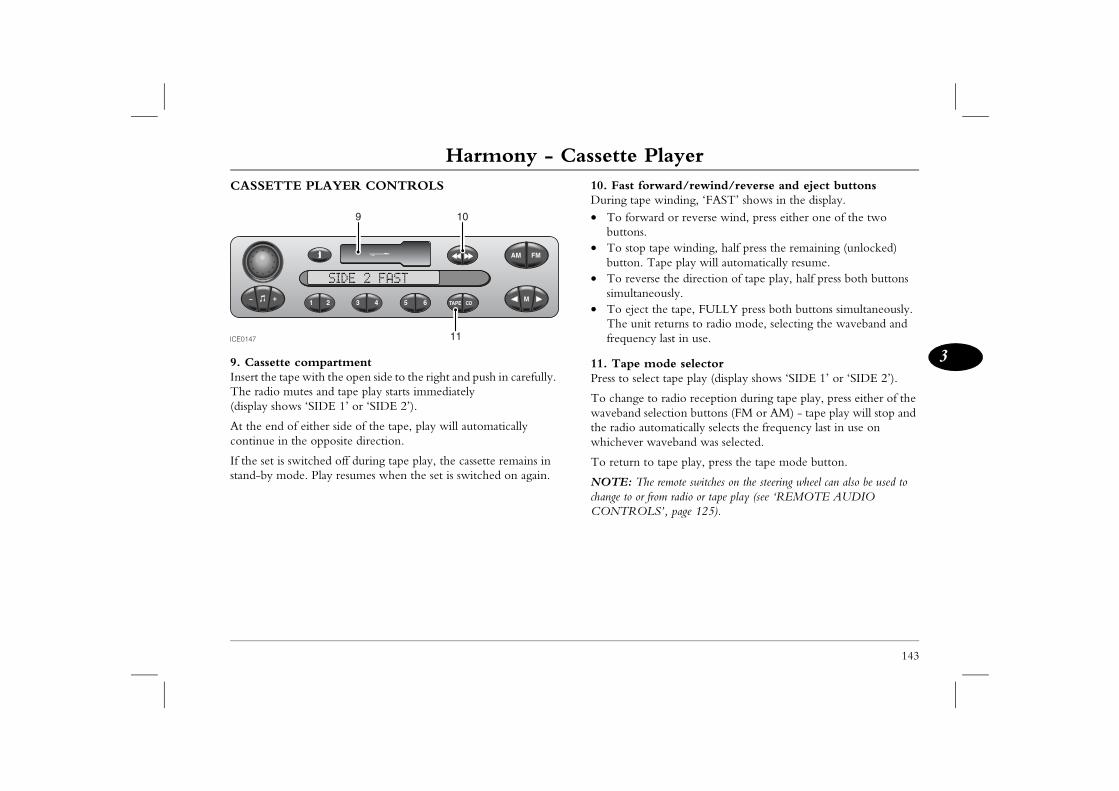
Harmony - Cassette Player
143
3
Harmony - Cassette Player rward/rewind/reverse and eject buttons winding, ‘FAST’ shows in the display.ard or reverse wind, press either one of the two
tape winding, half press the remaining (unlocked) ape play will automatically resume.
se the direction of tape play, half press both buttons eously. the tape, FULLY press both buttons simultaneously. returns to radio mode, selecting the waveband and y last in use.
ode selector ct tape play (display shows ‘SIDE 1’ or ‘SIDE 2’).
o radio reception during tape play, press either of the election buttons (FM or AM) - tape play will stop and tomatically selects the frequency last in use on aveband was selected.
tape play, press the tape mode button.
e remote switches on the steering wheel can also be used to rom radio or tape play (see ‘REMOTE AUDIO S’, page 125).
CASSETTE PLAYER CONTROLS
9. Cassette compartmentInsert the tape with the open side to the right and push in carefully. The radio mutes and tape play starts immediately(display shows ‘SIDE 1’ or ‘SIDE 2’).
At the end of either side of the tape, play will automatically continue in the opposite direction.
If the set is switched off during tape play, the cassette remains in stand-by mode. Play resumes when the set is switched on again.
10. Fast foDuring tape• To forw
buttons.• To stop
button. T• To rever
simultan• To eject
The unitfrequenc
11. Tape mPress to sele
To change twaveband sthe radio auwhichever w
To return to
NOTE: Thchange to or fCONTROL
ICE0147
9 10
11
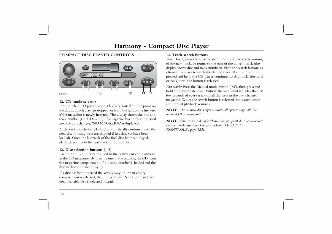
Harmony - Compact Disc PlayerHarmony - Compact Disc PlayerCOMPACT DISC PLAYER CONTROLS 14. Track search buttons
Skip: Briefly press the appropriate button to skip to the beginning of the next track, or return to the start of the current track (the
and track numbers). Press the search buttons as to reach the desired track. If either button is the CD player continues to skip tracks (forward button is released.
e Manual mode button (‘M’), then press and te search button; the audio unit will play the first ery track on all the discs in the autochanger the search button is released, fast search ceases ck resumes.
act disc player controls will operate only with the r unit.
ch and mode selection can be operated using the remote ing wheel (see ‘REMOTE AUDIO ge 125).
144
12. CD mode selectorPress to select CD player mode. Playback starts from the point on the disc at which play last stopped, or from the start of the first disc if the magazine is newly inserted. The display shows the disc and track number (i.e. ‘CD2 - 08’). If a magazine has not been inserted into the autochanger, 'NO MAGAZINE' is displayed.
At the end of each disc, playback automatically continues with the next disc (missing discs are skipped if less than six have been loaded). Once the last track of the final disc has been played, playback reverts to the first track of the first disc.
13. Disc selection buttons (1-6)Each button is numerically allied to the equivalent compartment in the CD magazine. By pressing one of the buttons, the CD from the magazine compartment of the same number is loaded and the first track commences playing.
If a disc has been inserted the wrong way up, or an empty compartment is selected, the display shows ‘NO DISC’ and the next available disc is selected instead.
display shows discoften as necessary pressed and held, or back) until the
Fast search: Press thhold the appropriafew seconds of evmagazine. When and normal playba
NOTE: The compoptional CD change
NOTE: Skip, searswitches on the steerCONTROLS’, pa
ICE0150 12 14 1413
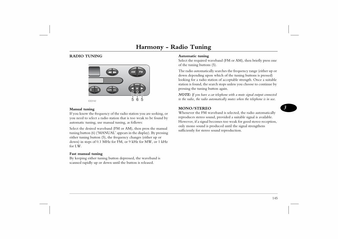
Harmony - Radio Tuning
145
3
Harmony - Radio Tuning tuningquired waveband (FM or AM), then briefly press one g buttons (5).
tomatically searches the frequency range (either up or ding upon which of the tuning buttons is pressed) a radio station of acceptable strength. Once a suitable nd, the search stops unless you choose to continue by
tuning button again.
ou have a car telephone with a mute signal output connected the radio automatically mutes when the telephone is in use.
TEREOhe FM waveband is selected, the radio automatically stereo sound, provided a suitable signal is available. a signal becomes too weak for good stereo reception, sound is produced until the signal strengthens for stereo sound reproduction.
RADIO TUNING
Manual tuningIf you know the frequency of the radio station you are seeking, or you need to select a radio station that is too weak to be found by automatic tuning, use manual tuning, as follows:
Select the desired waveband (FM or AM), then press the manual tuning button (6) (‘MANUAL’ appears in the display). By pressing either tuning button (5), the frequency changes (either up or down) in steps of 0.1 MHz for FM, or 9 kHz for MW, or 1 kHz for LW.
Fast manual tuningBy keeping either tuning button depressed, the waveband is scanned rapidly up or down until the button is released.
AutomaticSelect the reof the tunin
The radio audown depenlooking for station is foupressing the
NOTE: If yto the radio,
MONO/SWhenever treproduces However, ifonly mono sufficiently
ICE0142 5 6 5
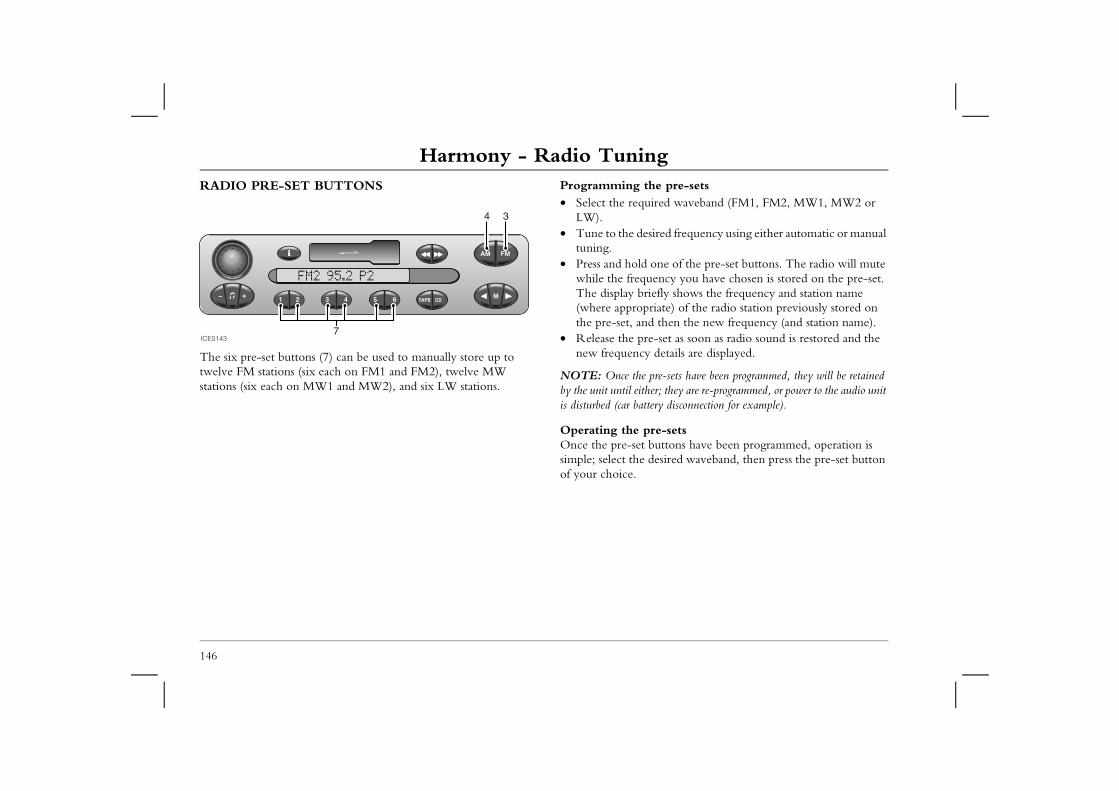
Harmony - Radio TuningRADIO PRE-SET BUTTONS Programming the pre-sets
• Select the required waveband (FM1, FM2, MW1, MW2 or
sired frequency using either automatic or manual
one of the pre-set buttons. The radio will mute ency you have chosen is stored on the pre-set.
iefly shows the frequency and station name riate) of the radio station previously stored on d then the new frequency (and station name). e-set as soon as radio sound is restored and the details are displayed.
pre-sets have been programmed, they will be retained er; they are re-programmed, or power to the audio unit ery disconnection for example).
re-setsbuttons have been programmed, operation is desired waveband, then press the pre-set button
146
The six pre-set buttons (7) can be used to manually store up to twelve FM stations (six each on FM1 and FM2), twelve MW stations (six each on MW1 and MW2), and six LW stations.
LW).• Tune to the de
tuning.• Press and hold
while the frequThe display br(where appropthe pre-set, an
• Release the prnew frequency
NOTE: Once the by the unit until eithis disturbed (car batt
Operating the pOnce the pre-set simple; select the of your choice.
ICE0143
4 3
7
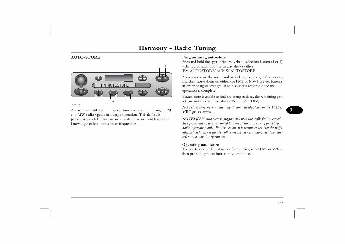
Harmony - Radio Tuning
147
3
ing auto-storeld the appropriate waveband selection button (3 or 4) utes and the display shows either
STORE’ or ‘MW AUTOSTORE’.
cans the waveband to find the six strongest frequencies res them on either the FM2 or MW2 pre-set buttons
signal strength. Radio sound is restored once the complete.
is unable to find six strong stations, the remaining pre-used (display shows ‘NO STATION’).
to-store overwrites any stations already stored on the FM2 or t buttons.
M auto-store is programmed with the traffic facility armed, ming will be limited to those stations capable of providing tion only. For this reason, it is recommended that the traffic
acility is switched off before the pre-set stations are stored and ore is programmed.
auto-storene of the auto-store frequencies, select FM2 or MW2, e pre-set button of your choice.
AUTO-STORE
Auto-store enables you to rapidly tune and store the strongest FM and MW radio signals in a single operation. This facility is particularly useful if you are in an unfamiliar area and have little knowledge of local transmitter frequencies.
ProgrammPress and ho- the radio m‘FM AUTO
Auto-store sand then stoin order of operation is
If auto-storesets are not
NOTE: AuMW2 pre-se
NOTE: If Fthen programtraffic informainformation fbefore auto-st
OperatingTo tune to othen press th
ICE0144
4 3
7
Harmony - Traffic & News InformationHarmony - Traffic & News InformationINFORMATION BROADCASTSOn the FM waveband, the RDS facility enables your radio to receive traffic and news information broadcasts from local radio
Selecting traffic informationBRIEFLY press the information button - the word ‘TRAFFIC’ illuminates in the display.
ouncements the display flashes ‘TRAFFIC’ e name of the radio station providing the
d to a weak FM signal or a radio station that ffic information, the message ‘STATION e display while the radio searches the waveband a radio station that does provide traffic casts.
may be impossible to find a traffic information will search the waveband twice; if a station the radio displays ‘NO TRAFFIC’ and returns hich it was previously tuned.
ffic information is switched on, occasional, and very radio may occur while the set searches for traffic reason, it is recommended that traffic information is ot needed.
nformation information button for approximately 2 seconds S’ illuminates in the display.
dcasts the display flashes ‘NEWS’ alternately he radio station providing the news information.
ic and news information can be selected at the same radio gives priority to traffic information.
148
stations that are linked to the same network as the station to which it is tuned.
Traffic and news information broadcasts can be selected by pressing the information button.
Once selected any available traffic and news information broadcasts are then received automatically as and when they occur (even if you are listening to cassette tapes or CDs).
During traffic annalternately with thinformation.
If the radio is tunecannot provide traSEEK’ flashes in thand then tunes to information broad
In remote areas, itstation. The radiocannot be found, to the station to w
NOTE: When trabrief, muting of the broadcasts. For this switched off when n
Selecting news iPress and hold the- the word ‘NEW
During news broawith the name of t
NOTE: Both trafftime. However, the
Harmony - Traffic & News Information
149
3
r Traffic and News announcements of traffic and news information broadcasts can be set tly from the volume required for other audio output cassette tape and CD), as follows:
raffic or news announcement, then during the djust the volume to the desired level (this is likely to be that required for other audio output). Once this been set, it will be memorised by the audio unit and tomatically next time a traffic or news announcement
rther adjustments to the volume can be made during ent traffic or news announcements.
y alarm announcementannouncements cannot be activated or deactivated by an emergency traffic or news announcement is (‘ALARM’ appears in the display), all other audio ill be overridden.
Switching off information broadcastsTraffic information: To switch off traffic information, briefly press the information button (‘TRAFFIC’ disappears from the display). This action will prevent traffic information broadcasts from being received until the button is pressed again.
News information: To switch off news information, press and hold the information button for approximately 2 seconds (‘NEWS’ disappears from the display). This action will prevent future news broadcasts from being received until the feature is reselected.
Unwanted information broadcasts can be aborted by similarly pressing the information button. In this case, because the feature is being disabled DURING an information broadcast, disablement is only temporary - the feature will return as soon as the next traffic or news information bulletin is broadcast.
Information broadcasts during tape or CD playWhen the radio is in either traffic or news information mode, CD or tape play will be interrupted by information broadcasts automatically as and when they occur.
Volume foThe volumeindependen(e.g. radio,
Wait for a tbroadcast, agreater thanvolume has replicated auis broadcast.
Note that fuany subsequ
EmergencEmergency the user. If transmitted functions w
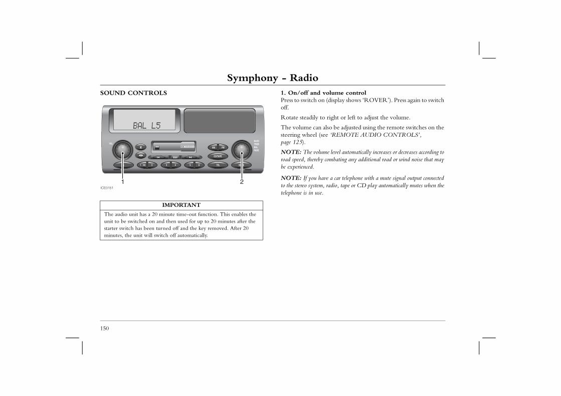
Symphony - RadioSymphony - RadioSOUND CONTROLS 1. On/off and volume control
Press to switch on (display shows ‘ROVER’). Press again to switch off.
right or left to adjust the volume.
lso be adjusted using the remote switches on the e ‘REMOTE AUDIO CONTROLS’,
e level automatically increases or decreases according to ombating any additional road or wind noise that may
e a car telephone with a mute signal output connected radio, tape or CD play automatically mutes when the
150
Rotate steadily to
The volume can asteering wheel (sepage 125).
NOTE: The volumroad speed, thereby cbe experienced.
NOTE: If you havto the stereo system, telephone is in use.
IMPORTANT
The audio unit has a 20 minute time-out function. This enables the unit to be switched on and then used for up to 20 minutes after the starter switch has been turned off and the key removed. After 20 minutes, the unit will switch off automatically.
ICE0151
1 2
Symphony - Radio
151
3
2. Audio selection controlPress one or more times to select bass, treble, balance or fader (display confirms selection), as described below.
Press and hold for two seconds to zero all audio settings (display shows ‘FLAT’).
Bass: Press once, then rotate to left or right to reduce or increase bass response. Display shows:• ‘BASS -9’ = minimum bass• ‘BASS 0’ = normal bass• ‘BASS +9’ = maximum bass
Treble: Press twice, then rotate to left or right to reduce or increase treble response. Display shows:• ‘TREB -9’ = minimum treble• ‘TREB 0’ = normal treble• ‘TREB +9’ = maximum treble
Balance: Press three times, then rotate to adjust balance between left and right speakers. Display shows:• ‘BAL R9’ = max sound from RIGHT• ‘BAL 0’ = equal balance• ‘BAL L9’ = max sound from LEFT
Fader: Press four times, then rotate to adjust balance between rear and front speakers. Display shows:• ‘FAD F9’ = max sound from FRONT• ‘FAD 0’ = equal balance• ‘FAD R9’ = max sound from REAR.
NOTE: After 8 seconds without further adjustment, the audio selection mode is cancelled automatically.
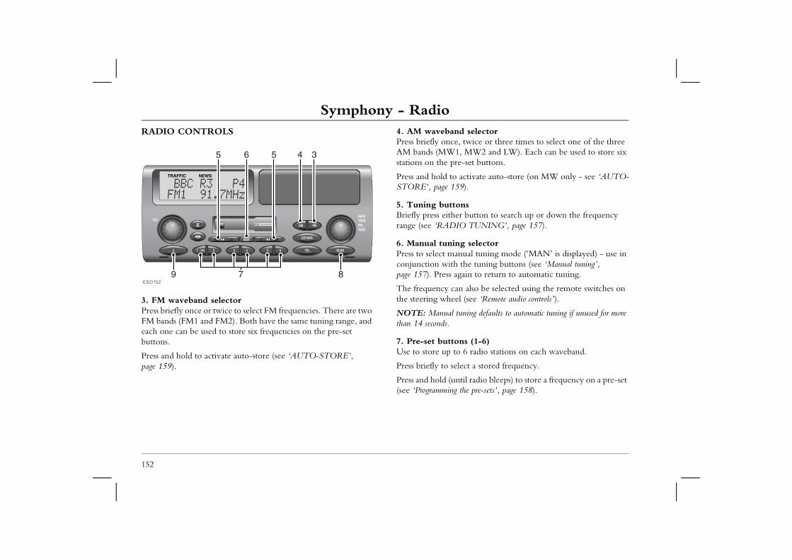
Symphony - RadioRADIO CONTROLS 4. AM waveband selector
Press briefly once, twice or three times to select one of the three AM bands (MW1, MW2 and LW). Each can be used to store six
-set buttons.
activate auto-store (on MW only - see ‘AUTO-9).
nsr button to search up or down the frequency O TUNING’, page 157).
g selectorual tuning mode (‘MAN’ is displayed) - use in the tuning buttons (see ‘Manual tuning’, ain to return to automatic tuning.
n also be selected using the remote switches on l (see ‘Remote audio controls’).
ning defaults to automatic tuning if unused for more
ns (1-6) 6 radio stations on each waveband.
ect a stored frequency.
til radio bleeps) to store a frequency on a pre-set the pre-sets’, page 158).
152
3. FM waveband selectorPress briefly once or twice to select FM frequencies. There are two FM bands (FM1 and FM2). Both have the same tuning range, and each one can be used to store six frequencies on the pre-set buttons.
Press and hold to activate auto-store (see ‘AUTO-STORE’, page 159).
stations on the pre
Press and hold to STORE’, page 15
5. Tuning buttoBriefly press eitherange (see ‘RADI
6. Manual tuninPress to select manconjunction with page 157). Press ag
The frequency cathe steering whee
NOTE: Manual tuthan 14 seconds.
7. Pre-set buttoUse to store up to
Press briefly to sel
Press and hold (un(see ‘Programming
ICE01529 7 8
34565
Symphony - Radio
153
3
8. Scan mode buttonPress to scan through all frequencies on the chosen waveband (each radio station will be played for 5 seconds). Press again to cancel the scan. See ‘Waveband scan’, page 157.
9. Traffic and news informationPress briefly to switch on (or switch off) Traffic information mode - FM waveband only (see ‘Selecting traffic information’, page 160).
Press and hold for 2 seconds to switch on (or switch off) News mode - FM waveband only (see ‘Selecting news information’, page 160).
Press briefly to return to normal radio, tape or CD reception during a traffic or news announcement.
NOTE: Both traffic and news information can be operational at the same time.
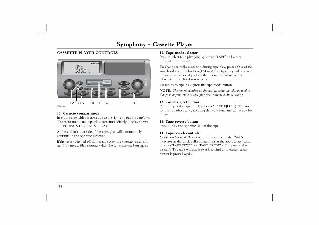
Symphony - Cassette PlayerSymphony - Cassette PlayerCASSETTE PLAYER CONTROLS 11. Tape mode selector
Press to select tape play (display shows ‘TAPE’ and either ‘SIDE-1’ or ‘SIDE-2’).
o reception during tape play, press either of the n buttons (FM or AM) - tape play will stop and ically selects the frequency last in use on and was selected.
play, press the tape mode button.
te switches on the steering wheel can also be used to dio or tape play (see ‘Remote audio controls’).
t buttontape (display shows ‘TAPE EJECT’). The unit ode, selecting the waveband and frequency last
buttonpposite side of the tape.
controls: With the unit in manual mode (‘MAN’ splay illuminated), press the appropriate search WD’ or ‘TAPE FREW’ will appear in the
will fast forward/rewind until either search gain.
154
10. Cassette compartmentInsert the tape with the open side to the right and push in carefully. The radio mutes and tape play starts immediately (display shows ‘TAPE’ and ‘SIDE-1’ or ‘SIDE-2’).
At the end of either side of the tape, play will automatically continue in the opposite direction.
If the set is switched off during tape play, the cassette remains in stand-by mode. Play resumes when the set is switched on again.
To change to radiwaveband selectiothe radio automatwhichever waveb
To return to tape
NOTE: The remochange to or from ra
12. Cassette ejecPress to eject the returns to radio min use.
13. Tape reversePress to play the o
14. Tape searchFast forward/rewindindicator in the dibutton (‘TAPE FFdisplay). The tapebutton is pressed a
ICE015312 13 15 14 10 14 11 16
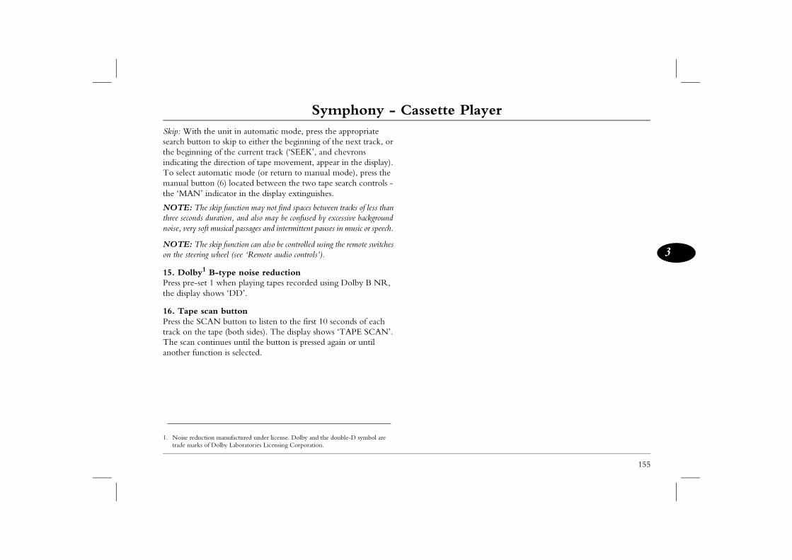
Symphony - Cassette Player
155
3
Skip: With the unit in automatic mode, press the appropriate search button to skip to either the beginning of the next track, or the beginning of the current track (‘SEEK’, and chevrons indicating the direction of tape movement, appear in the display). To select automatic mode (or return to manual mode), press the manual button (6) located between the two tape search controls - the ‘MAN’ indicator in the display extinguishes.
NOTE: The skip function may not find spaces between tracks of less than three seconds duration, and also may be confused by excessive background noise, very soft musical passages and intermittent pauses in music or speech.
NOTE: The skip function can also be controlled using the remote switches on the steering wheel (see ‘Remote audio controls’).
15. Dolby1 B-type noise reduction Press pre-set 1 when playing tapes recorded using Dolby B NR, the display shows ‘DD’.
16. Tape scan buttonPress the SCAN button to listen to the first 10 seconds of each track on the tape (both sides). The display shows ‘TAPE SCAN’. The scan continues until the button is pressed again or until another function is selected.
1. Noise reduction manufactured under license. Dolby and the double-D symbol are trade marks of Dolby Laboratories Licensing Corporation.
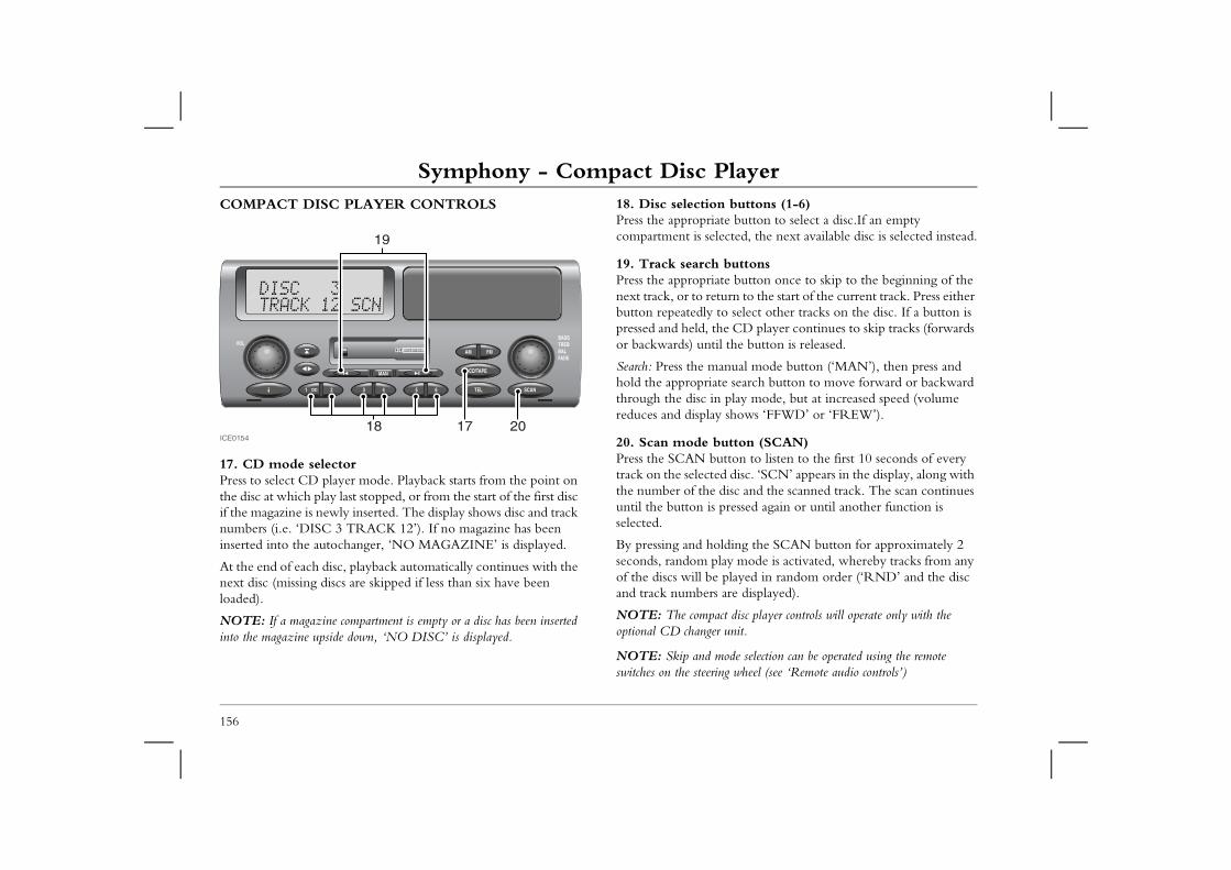
Symphony - Compact Disc PlayerSymphony - Compact Disc PlayerCOMPACT DISC PLAYER CONTROLS 18. Disc selection buttons (1-6)
Press the appropriate button to select a disc.If an empty compartment is selected, the next available disc is selected instead.
buttonsate button once to skip to the beginning of the turn to the start of the current track. Press either to select other tracks on the disc. If a button is he CD player continues to skip tracks (forwards il the button is released.
anual mode button (‘MAN’), then press and te search button to move forward or backward
n play mode, but at increased speed (volume y shows ‘FFWD’ or ‘FREW’).
button (SCAN)utton to listen to the first 10 seconds of every ed disc. ‘SCN’ appears in the display, along with disc and the scanned track. The scan continues pressed again or until another function is
olding the SCAN button for approximately 2 lay mode is activated, whereby tracks from any played in random order (‘RND’ and the disc
s are displayed).
act disc player controls will operate only with the r unit.
mode selection can be operated using the remote ing wheel (see ‘Remote audio controls’)
156
17. CD mode selectorPress to select CD player mode. Playback starts from the point on the disc at which play last stopped, or from the start of the first disc if the magazine is newly inserted. The display shows disc and track numbers (i.e. ‘DISC 3 TRACK 12’). If no magazine has been inserted into the autochanger, ‘NO MAGAZINE’ is displayed.
At the end of each disc, playback automatically continues with the next disc (missing discs are skipped if less than six have been loaded).
NOTE: If a magazine compartment is empty or a disc has been inserted into the magazine upside down, ‘NO DISC’ is displayed.
19. Track searchPress the approprinext track, or to rebutton repeatedlypressed and held, tor backwards) unt
Search: Press the mhold the appropriathrough the disc ireduces and displa
20. Scan mode Press the SCAN btrack on the selectthe number of theuntil the button isselected.
By pressing and hseconds, random pof the discs will beand track number
NOTE: The compoptional CD change
NOTE: Skip and switches on the steer
ICE0154
19
201718
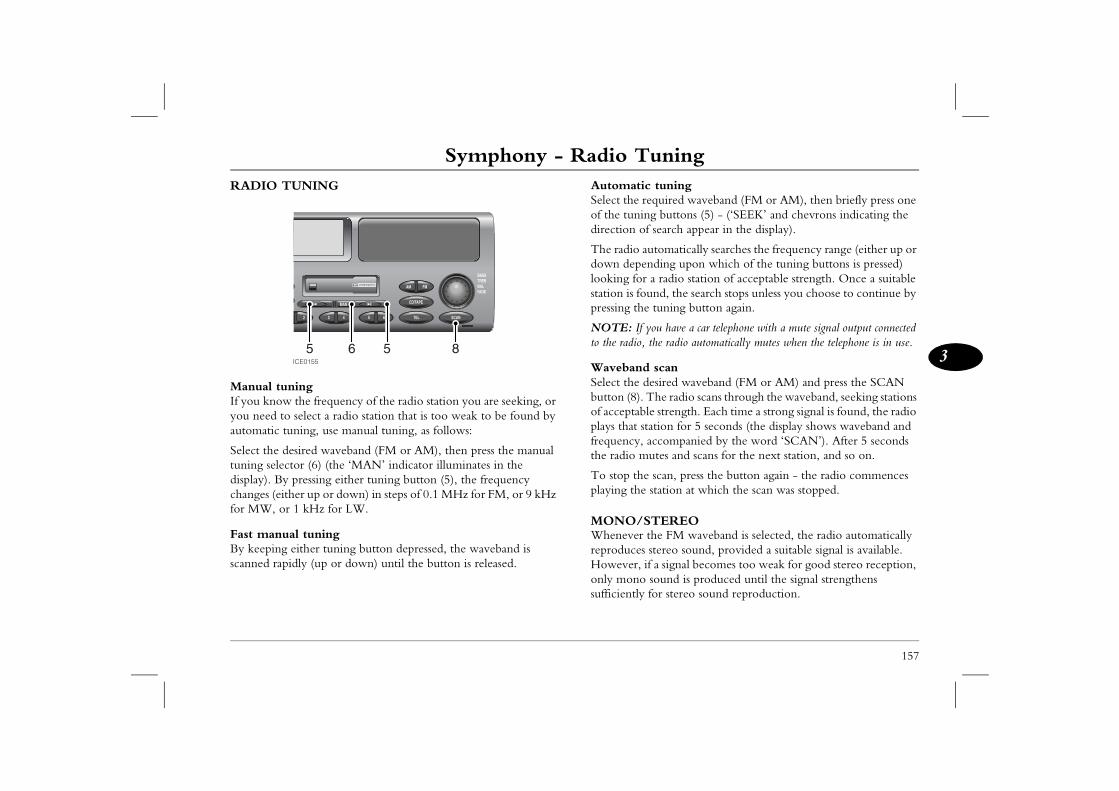
Symphony - Radio Tuning
157
3
Symphony - Radio Tuning tuningquired waveband (FM or AM), then briefly press one g buttons (5) - (‘SEEK’ and chevrons indicating the search appear in the display).
tomatically searches the frequency range (either up or ding upon which of the tuning buttons is pressed) a radio station of acceptable strength. Once a suitable nd, the search stops unless you choose to continue by
tuning button again.
ou have a car telephone with a mute signal output connected the radio automatically mutes when the telephone is in use.
scanesired waveband (FM or AM) and press the SCAN he radio scans through the waveband, seeking stations
e strength. Each time a strong signal is found, the radio ation for 5 seconds (the display shows waveband and ccompanied by the word ‘SCAN’). After 5 seconds utes and scans for the next station, and so on.
scan, press the button again - the radio commences station at which the scan was stopped.
TEREOhe FM waveband is selected, the radio automatically stereo sound, provided a suitable signal is available. a signal becomes too weak for good stereo reception, sound is produced until the signal strengthens for stereo sound reproduction.
RADIO TUNING
Manual tuningIf you know the frequency of the radio station you are seeking, or you need to select a radio station that is too weak to be found by automatic tuning, use manual tuning, as follows:
Select the desired waveband (FM or AM), then press the manual tuning selector (6) (the ‘MAN’ indicator illuminates in the display). By pressing either tuning button (5), the frequency changes (either up or down) in steps of 0.1 MHz for FM, or 9 kHz for MW, or 1 kHz for LW.
Fast manual tuningBy keeping either tuning button depressed, the waveband is scanned rapidly (up or down) until the button is released.
AutomaticSelect the reof the tunindirection of
The radio audown depenlooking for station is foupressing the
NOTE: If yto the radio,
WavebandSelect the dbutton (8). Tof acceptablplays that stfrequency, athe radio m
To stop theplaying the
MONO/SWhenever treproduces However, ifonly mono sufficiently
ICE0155
8565
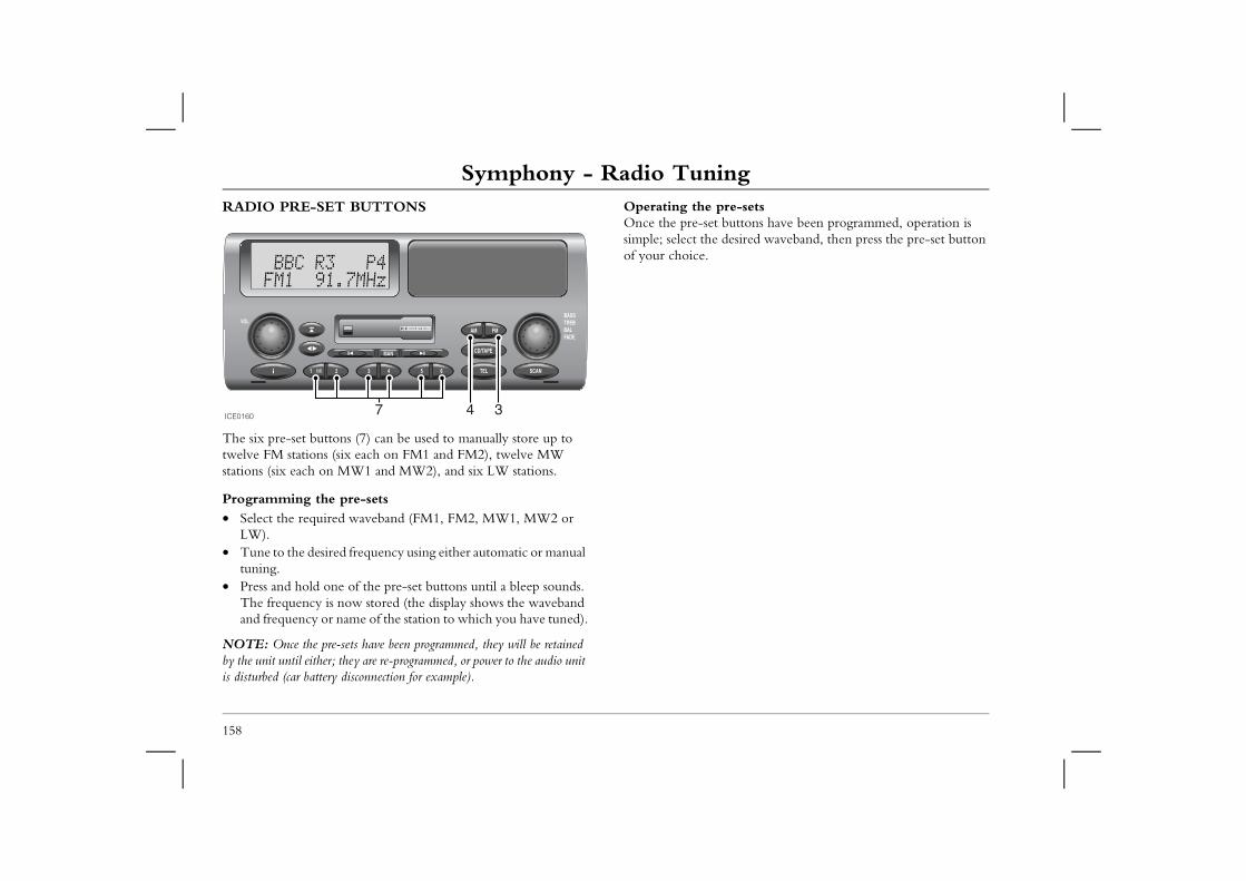
Symphony - Radio TuningRADIO PRE-SET BUTTONS Operating the pre-sets
Once the pre-set buttons have been programmed, operation is simple; select the desired waveband, then press the pre-set button
158
The six pre-set buttons (7) can be used to manually store up to twelve FM stations (six each on FM1 and FM2), twelve MW stations (six each on MW1 and MW2), and six LW stations.
Programming the pre-sets• Select the required waveband (FM1, FM2, MW1, MW2 or
LW).• Tune to the desired frequency using either automatic or manual
tuning.• Press and hold one of the pre-set buttons until a bleep sounds.
The frequency is now stored (the display shows the waveband and frequency or name of the station to which you have tuned).
NOTE: Once the pre-sets have been programmed, they will be retained by the unit until either; they are re-programmed, or power to the audio unit is disturbed (car battery disconnection for example).
of your choice.
ICE0160 4 37
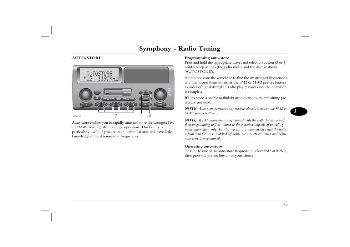
Symphony - Radio Tuning
159
3
ing auto-storeld the appropriate waveband selection button (3 or 4) sounds (the radio mutes and the display shows RE’).
cans the waveband to find the six strongest frequencies res them on either the FM2 or MW2 pre-set buttons ignal strength. Radio play restores once the operation
is unable to find six strong stations, the remaining pre-used.
to-store overwrites any stations already stored on the FM2 or t buttons.
M auto-store is programmed with the traffic facility armed, ming will be limited to those stations capable of providing tion only. For this reason, it is recommended that the traffic
acility is switched off before the pre-sets are stored and before programmed.
auto-storene of the auto-store frequencies, select FM2 or MW2, e pre-set button of your choice.
AUTO-STORE
Auto-store enables you to rapidly tune and store the strongest FM and MW radio signals in a single operation. This facility is particularly useful if you are in an unfamiliar area and have little knowledge of local transmitter frequencies.
ProgrammPress and hountil a bleep‘AUTOSTO
Auto-store sand then stoin order of sis complete.
If auto-storesets are not
NOTE: AuMW2 pre-se
NOTE: If Fthen programtraffic informainformation fauto-store is
OperatingTo tune to othen press th
ICE0156 4 37
Symphony - Traffic & News InformationSymphony - Traffic & News InformationINFORMATION BROADCASTSOn the FM waveband, the RDS facility enables your radio to receive traffic and news information broadcasts from local radio
Selecting traffic informationBRIEFLY press the information button - the ‘TRAFFIC’ indicator illuminates in the display.
ouncements the display slowly flashes ’.
d to an FM radio station that does not provide , the message ‘NO TRAFFIC’ is displayed.
d to an FM signal that is too weak to provide , the message ‘STATION SEEK’ is displayed arches the waveband and tunes to a signal that is broadcast traffic information.
may be impossible to find a traffic information will search the waveband twice; if a station the radio switches off traffic and returns to the t was previously tuned.
ffic information is switched on, occasional, and very radio may occur while the set searches for traffic reason, it is recommended that traffic information is ot needed.
nformation information button until a bleep sounds - the illuminates in the display.
dcasts the display flashes ‘NEWS’ alternately he radio station providing the news information.
ic and news information can be selected at the same radio gives priority to which ever broadcast commenced n source cannot interrupt another!
160
stations that are linked to the same network as the station to which it is tuned.
Traffic and news information broadcasts can be selected by pressing the information button.
Once selected any available traffic and news information broadcasts are then received automatically as and when they occur (even if you are listening to cassette tapes or CDs).
During traffic ann‘TRAFFIC INFO
If the radio is tunetraffic information
If the radio is tunetraffic informationwhile the radio sestrong enough to
In remote areas, itstation. The radiocannot be found, station to which i
NOTE: When trabrief, muting of the broadcasts. For this switched off when n
Selecting news iPress and hold the‘NEWS’ indicator
During news broawith the name of t
NOTE: Both trafftime. However, the first - one informatio
Symphony - Traffic & News Information
161
3
r Traffic and News announcements of traffic and news information broadcasts can be set tly from the volume required for other audio output cassette tape and CD), as follows:
raffic or news announcement, then during the djust the volume to the desired level (this is likely to be that required for other audio output). Once this been set, it will be memorised by the audio unit and tomatically next time a traffic or news announcement
rther adjustments to the volume can be made during ent traffic or news announcements.
y alarm announcementannouncements cannot be activated or deactivated by an emergency traffic or news announcement is (‘ALARM’ appears in the display), all other audio ill be overridden.
Switching off information broadcastsTraffic information: To switch off traffic information, briefly press the information button (the ‘TRAFFIC’ indicator disappears from the display). This action will prevent traffic information broadcasts from being received until the button is pressed again.
News information: To switch off news information, press and hold the information button for approximately 2 seconds (a bleep sounds and the NEWS indicator disappears from the display).
Unwanted information broadcasts can be aborted by similarly pressing the information button. In this case, because the feature is being disabled DURING an information broadcast, disablement is only temporary - the feature will return as soon as the next traffic or news information bulletin is broadcast.
Information broadcasts during tape or CD playWhen the radio is in either traffic or news information mode, CD or tape play will be interrupted by information broadcasts automatically as and when they occur.
Volume foThe volumeindependen(e.g. radio,
Wait for a tbroadcast, agreater thanvolume has replicated auis broadcast.
Note that fuany subsequ
EmergencEmergency the user. If transmitted functions w
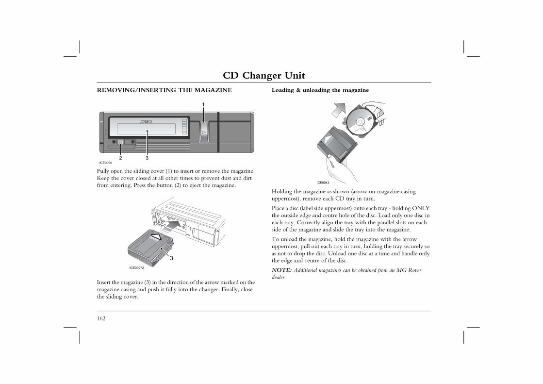
CD Changer UnitCD Changer UnitREMOVING/INSERTING THE MAGAZINE Loading & unloading the magazine
zine as shown (arrow on magazine casing ve each CD tray in turn.
ide uppermost) onto each tray - holding ONLY nd centre hole of the disc. Load only one disc in ly align the tray with the parallel slots on each ne and slide the tray into the magazine.
gazine, hold the magazine with the arrow ut each tray in turn, holding the tray securely so disc. Unload one disc at a time and handle only re of the disc.
l magazines can be obtained from an MG Rover
1
ICE0043
162
Fully open the sliding cover (1) to insert or remove the magazine. Keep the cover closed at all other times to prevent dust and dirt from entering. Press the button (2) to eject the magazine.
Insert the magazine (3) in the direction of the arrow marked on the magazine casing and push it fully into the changer. Finally, close the sliding cover.
Holding the magauppermost), remo
Place a disc (label sthe outside edge aeach tray. Correctside of the magazi
To unload the mauppermost, pull oas not to drop thethe edge and cent
NOTE: Additionadealer.
ICE00962 3
ICE0097A
3
CD Changer Unit
163
3
FOR COMPACT DISCSondensation and heat can damage discs. Always following precautions:
uch the horizontal playing surface (the unlabelled side) andle discs by holding the outer edges, or the edge of ole and the outer edge, between finger and thumb.
return discs to their boxes after use (dirt detracts from uality).
ave the disc or the box exposed to excessive heat or ht!
e a solvent or abrasive cleaner! Dust or dirt should be m the playing surface by wiping with a clean, dry, lint-
ways wipe in a straight line from the centre to the edge
CARING Dirt, dust, cobserve the
NEVER toof a disc! Hthe central h
ALWAYS the sound q
NEVER ledirect sunlig
NEVER usremoved frofree cloth alof the disc!
IMPORTANT
• Use standard 12cm CDs only. • DO NOT use irregularly shaped or damaged CDs - these may
damage the compact disc changer. • 8cm CD singles must NOT be used, even if a CD adaptor is
fitted.• If temperatures in excess of 70°C occur in the autochanger, the
message ‘HIGH TEMP’ will be displayed - change to radio or tape mode until the unit has cooled.
• The CD autochanger should only be used as described - any other application or method of use could result in the user being exposed to invisible laser radiation exceeding the limit of laser class 1.
Care of Cassette Player and TapesCare of Cassette Player and TapesCARE OF CASSETTE PLAYER AND TAPESUse only good quality tapes with a maximum capacity of ninety minutes (C90). Check that both spools rotate freely and remove
Cassette tapes• Always store cassettes in their boxes when not in use.
ssettes in the vehicle during extremes of particular, do not leave tapes in direct sunlight rp and become unusable, or jam the tape player
r rewind tapes every 8 to 10 plays to prevent oming too tightly wound.els attached to the cassette are glued firmly in
e tapes in the cassette player for more than a few old or humid conditions - the oxides on the tape ntaminate the cassette player mechanism.
nuous playing, cassettes may become hot to touch.This ot harm good quality tape.
164
any loose turns at the start of the tape by winding one spool with a pen or pencil.
Cassette playerIn use, the tape head accumulates dust and contamination, gradually impairing sound reproduction and, in extreme cases, reducing volume too. To combat contamination, clean the tape head periodically (after approximately every 20 hours playing time) by passing a wet type cleaning cassette through the player.
NOTE: Because your cassette player is fitted with auto reverse, the cleaning cassette must be played in both directions.
The tape will require more frequent cleaning in winter, as contamination is greater in conditions of low temperature and increased humidity. However, the use of good quality tapes keeps the build up to a minimum.
• Never leave catemperature. Inas they may wamechanism.
• Fast forward, othem from bec
• Ensure that labplace.
• DO NOT leavhours in very csurface may co
NOTE: After contiis normal and will n
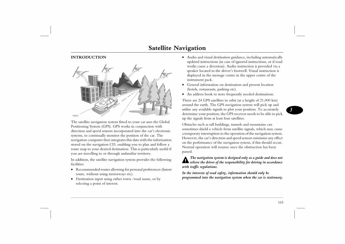
Satellite Navigation
165
3
Satellite Navigation d visual destination guidance, including automatically instructions (in case of ignored instructions, or if road use a diversion). Audio instruction is provided via a ocated in the driver’s footwell. Visual instruction is in the message centre in the upper centre of the nt pack.information on destination and present location estaurants, parking etc).ss book to store frequently needed destinations.
4 GPS satellites in orbit (at a height of 21,000 km) earth. The GPS navigation system will pick up and vailable signals to plot your position. To accurately our position, the GPS receiver needs to be able to pick ls from at least four satellites.
ch as tall buildings, tunnels and mountains can hield a vehicle from satellite signals, which may cause interruption to the operation of the navigation system. e car’s direction and speed sensors minimise any effect rmance of the navigation system, if this should occur. ration will resume once the obstruction has been
vigation system is designed only as a guide and does not the driver of the responsibility for driving in accordance regulations.
sts of road safety, information should only be into the navigation system when the car is stationary.
INTRODUCTION
The satellite navigation system fitted to your car uses the Global Positioning System (GPS). GPS works in conjunction with direction and speed sensors incorporated into the car’s electronic systems, to continually monitor the position of the car. The navigation computer then integrates this data with the information stored on the navigation CD, enabling you to plan and follow a route map to your desired destination. This is particularly useful if you are travelling to or through unfamiliar territory.
In addition, the satellite navigation system provides the following facilities:• Recommended routes allowing for personal preferences (fastest
route, without using motorways etc).• Destination input using either town /road name, or by
selecting a point of interest.
• Audio anupdated works caspeaker ldisplayedinstrume
• General (hotels, r
• An addre
There are 2around the utilise any adetermine yup the signa
Obstacles susometimes sa temporaryHowever, thon the perfoNormal opepassed.
The narelieve
with traffic
In the intereprogrammed
H2931
Satellite NavigationOPERATING INFORMATIONThe navigation system can only provide information and guidance for the area covered by the navigation CD - ensure that you are
166
using the latest version of the correct CD for your country.
Some maps contain areas of unattributed geometry. In these areas the navigation system will announce that “you are leaving the registered road network”. The navigation screen will revert to a ‘Target Direction Arrow’ which displays the direction and distance to your destination ‘as the crow flies’. No audible instructions will be given in these areas,.
NOTE: Navigation CDs are updated approximately every 6 months and you will automatically receive the first update free, along with information on how to order further updates.
Under normal operating conditions, the satellite navigation system requires approximately 8 seconds to confirm the car's position using the satellites.
If the car battery has been disconnected, or if the car has been transported to a new location on another vehicle (e.g. by trailer or train), the navigation system will require approximately 15 minutes to identify the new position. Entering the new location manually will reduce this delay (see ‘ENTERING THE CAR’S POSITION’, page 178).
Metallic objects interfere with satellite signal reception. For this reason, do not store any metallic objects in close proximity to the satellite receiver, located on the rear shelf.
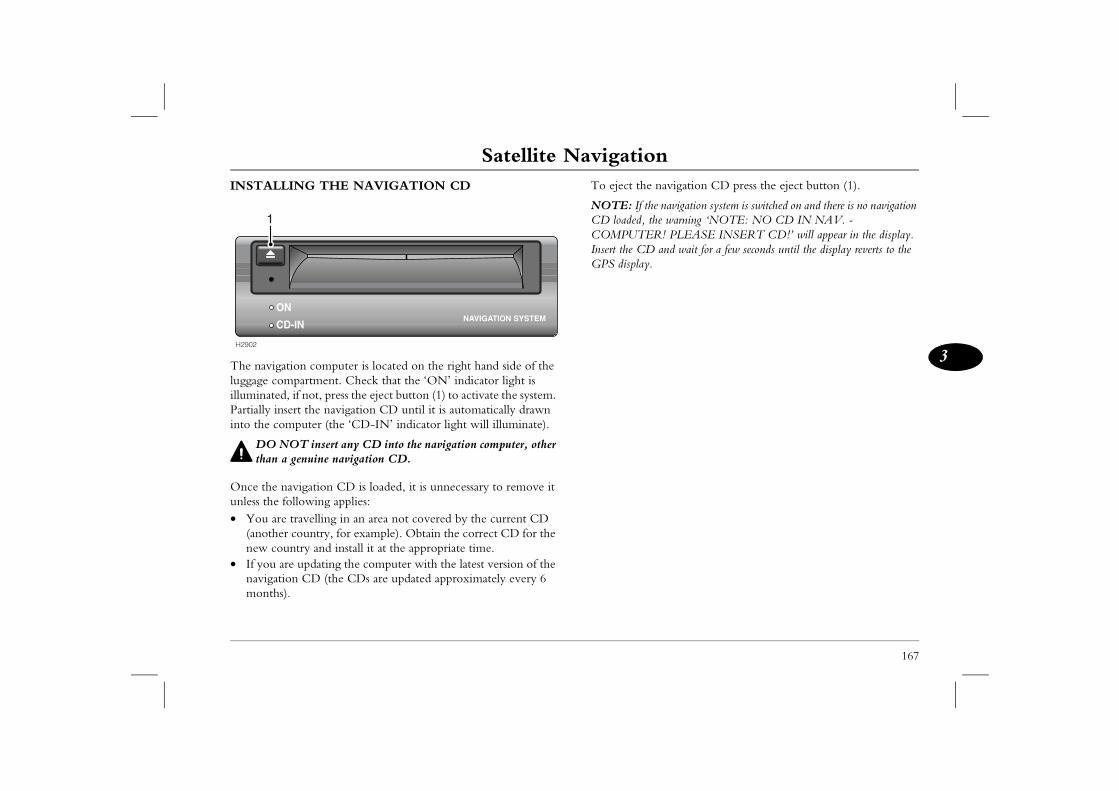
Satellite Navigation
167
3
navigation CD press the eject button (1).
e navigation system is switched on and there is no navigation the warning ‘NOTE: NO CD IN NAV. - R! PLEASE INSERT CD!’ will appear in the display. and wait for a few seconds until the display reverts to the
.
INSTALLING THE NAVIGATION CD
The navigation computer is located on the right hand side of the luggage compartment. Check that the ‘ON’ indicator light is illuminated, if not, press the eject button (1) to activate the system. Partially insert the navigation CD until it is automatically drawn into the computer (the ‘CD-IN’ indicator light will illuminate).
DO NOT insert any CD into the navigation computer, other than a genuine navigation CD.
Once the navigation CD is loaded, it is unnecessary to remove it unless the following applies:• You are travelling in an area not covered by the current CD
(another country, for example). Obtain the correct CD for the new country and install it at the appropriate time.
• If you are updating the computer with the latest version of the navigation CD (the CDs are updated approximately every 6 months).
To eject the
NOTE: If thCD loaded, COMPUTEInsert the CDGPS display
H2902
ON
CD-IN
1
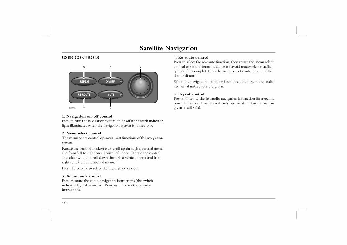
Satellite NavigationUSER CONTROLS 4. Re-route control
Press to select the re-route function, then rotate the menu select control to set the detour distance (to avoid roadworks or traffic
le). Press the menu select control to enter the
ion computer has plotted the new route, audio ions are given.
olhe last audio navigation instruction for a second unction will only operate if the last instruction
168
1. Navigation on/off controlPress to turn the navigation system on or off (the switch indicator light illuminates when the navigation system is turned on).
2. Menu select controlThe menu select control operates most functions of the navigation system.
Rotate the control clockwise to scroll up through a vertical menu and from left to right on a horizontal menu. Rotate the control anti-clockwise to scroll down through a vertical menu and from right to left on a horizontal menu.
Press the control to select the highlighted option.
3. Audio mute controlPress to mute the audio navigation instructions (the switch indicator light illuminates). Press again to reactivate audio instructions.
queues, for exampdetour distance.
When the navigatand visual instruct
5. Repeat contrPress to listen to ttime. The repeat fgiven is still valid.H2903 34
1 25
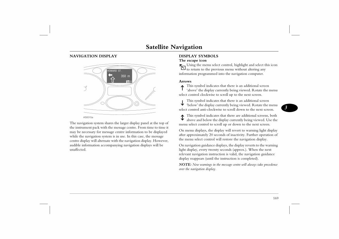
Satellite Navigation
169
3
SYMBOLS icon
the menu select control, highlight and select this icon rn to the previous menu without altering any programmed into the navigation computer.
mbol indicates that there is an additional screen ’ the display currently being viewed. Rotate the menu l clockwise to scroll up to the next screen.
mbol indicates that there is an additional screen ’ the display currently being viewed. Rotate the menu l anti-clockwise to scroll down to the next screen.
mbol indicates that there are additional screens, both and below the display currently being viewed. Use the control to scroll up or down to the next screen.
isplays, the display will revert to warning light display imately 20 seconds of inactivity. Further operation of lect control will restore the navigation display.
on guidance displays, the display reverts to the warning , every twenty seconds (approx.). When the next igation instruction is valid, the navigation guidance pears (until the instruction is completed).
w warnings in the message centre will always take precedence gation display.
NAVIGATION DISPLAY
The navigation system shares the larger display panel at the top of the instrument pack with the message centre. From time to time it may be necessary for message centre information to be displayed while the navigation system is in use. In this case, the message centre display will alternate with the navigation display. However, audible information accompanying navigation displays will be unaffected.
DISPLAYThe escape
Using to retu
information
ArrowsThis sy‘above
select contro
This sy‘below
select contro
This syabove
menu select
On menu dafter approxthe menu se
On navigatilight displayrelevant navdisplay reap
NOTE: Neover the navi
AS0015a
350 m
HOWARD ST .
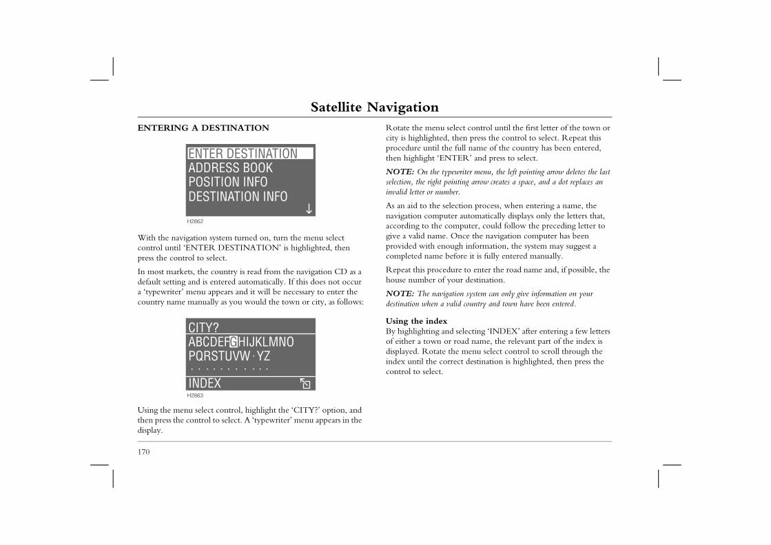
Satellite NavigationENTERING A DESTINATION Rotate the menu select control until the first letter of the town or
city is highlighted, then press the control to select. Repeat this procedure until the full name of the country has been entered,
TER’ and press to select.
pewriter menu, the left pointing arrow deletes the last ointing arrow creates a space, and a dot replaces an ber.
lection process, when entering a name, the ter automatically displays only the letters that, omputer, could follow the preceding letter to Once the navigation computer has been ugh information, the system may suggest a efore it is fully entered manually.
dure to enter the road name and, if possible, the your destination.
ation system can only give information on your alid country and town have been entered.
d selecting ‘INDEX’ after entering a few letters r road name, the relevant part of the index is the menu select control to scroll through the rrect destination is highlighted, then press the
170
With the navigation system turned on, turn the menu select control until ‘ENTER DESTINATION’ is highlighted, then press the control to select.
In most markets, the country is read from the navigation CD as a default setting and is entered automatically. If this does not occur a ‘typewriter’ menu appears and it will be necessary to enter the country name manually as you would the town or city, as follows:
Using the menu select control, highlight the ‘CITY?’ option, and then press the control to select. A ‘typewriter’ menu appears in the display.
then highlight ‘EN
NOTE: On the tyselection, the right pinvalid letter or num
As an aid to the senavigation compuaccording to the cgive a valid name.provided with enocompleted name b
Repeat this procehouse number of
NOTE: The navigdestination when a v
Using the indexBy highlighting anof either a town odisplayed. Rotate index until the cocontrol to select.
ADDRESS BOOKPOSITION INFODESTINATION INFO
ENTER DESTINATION
H2862
ABCDEFGHIJKLMNOHIJKLMNOABCDEFPQRSTUVW YZ
INDEX
CITY?
H2863
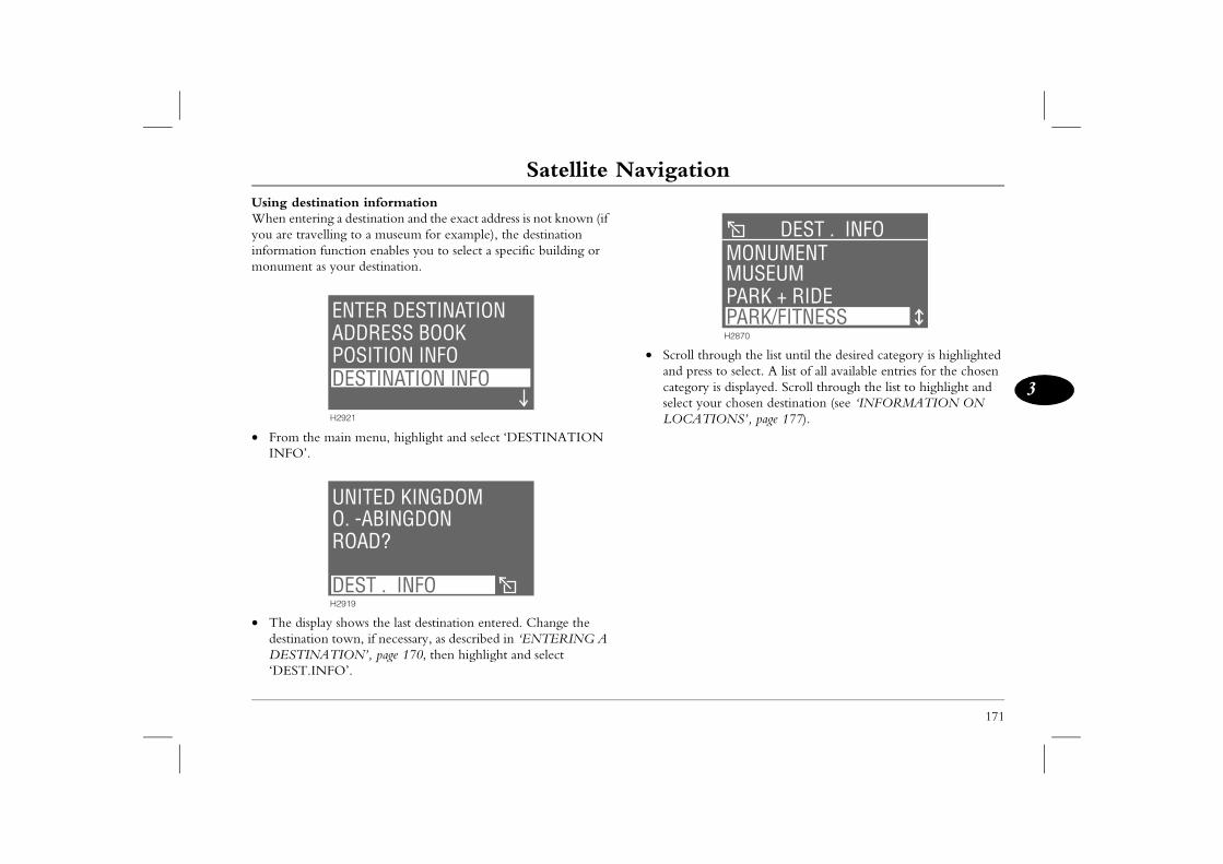
Satellite Navigation
171
3
rough the list until the desired category is highlighted s to select. A list of all available entries for the chosen is displayed. Scroll through the list to highlight and ur chosen destination (see ‘INFORMATION ON IONS’, page 177).
MUSEUMMONUMENT
DEST . INFO
PARK + RIDEDEST . GUIDEH2870
PARK/FITNESS
Using destination informationWhen entering a destination and the exact address is not known (if you are travelling to a museum for example), the destination information function enables you to select a specific building or monument as your destination.
• From the main menu, highlight and select ‘DESTINATION INFO’.
• The display shows the last destination entered. Change the destination town, if necessary, as described in ‘ENTERING A DESTINATION’, page 170, then highlight and select ‘DEST.INFO’.
• Scroll thand prescategoryselect yoLOCAT
ADDRESS BOOKPOSITION INFODESTINATION INFO
ENTER DESTINATION
H2921
O. -ABINGDONROAD?
UNITED KINGDOM
DEST . INFOH2919
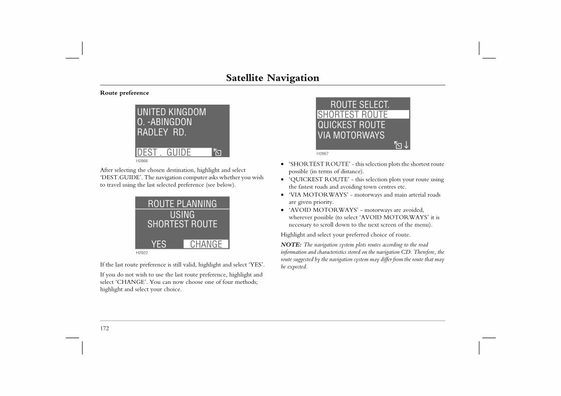
Satellite NavigationRoute preference
ROUTE’ - this selection plots the shortest route ms of distance).
OUTE’ - this selection plots your route using s and avoiding town centres etc.WAYS’ - motorways and main arterial roads
ity.ORWAYS’ - motorways are avoided,
ble (to select ‘AVOID MOTORWAYS’ it is roll down to the next screen of the menu).
ct your preferred choice of route.
ation system plots routes according to the road acteristics stored on the navigation CD. Therefore, the e navigation system may differ from the route that may
ORTEST ROUTEICKEST ROUTE
A MOTORWAYS
ROUTE SELECT.
7
172
After selecting the chosen destination, highlight and select ‘DEST.GUIDE’. The navigation computer asks whether you wish to travel using the last selected preference (see below).
If the last route preference is still valid, highlight and select ‘YES’.
If you do not wish to use the last route preference, highlight and select ‘CHANGE’. You can now choose one of four methods; highlight and select your choice.
• ‘SHORTEST possible (in ter
• ‘QUICKEST Rthe fastest road
• ‘VIA MOTORare given prior
• ‘AVOID MOTwherever possinecessary to sc
Highlight and sele
NOTE: The naviginformation and charroute suggested by thbe expected.
O. -ABINGDONRADLEY RD.
UNITED KINGDOM
DEST . GUIDEH2866
SHORTEST ROUTEUSING
ROUTE PLANNING
YESH2922
CHANGE
SHQUVI
H286
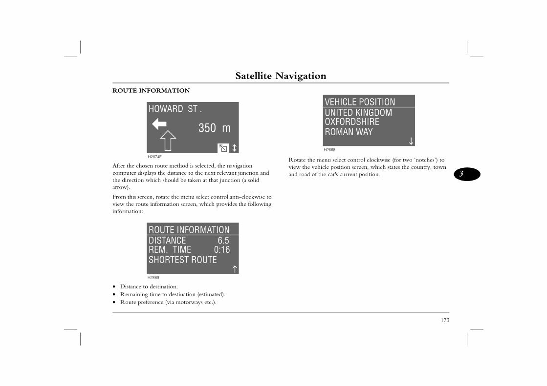
Satellite Navigation
173
3
menu select control clockwise (for two ‘notches’) to hicle position screen, which states the country, town the car's current position.
OXFORDSHIREUNITED KINGDOMVEHICLE POSITION
ROMAN WAY
H2868
ROUTE INFORMATION
After the chosen route method is selected, the navigation computer displays the distance to the next relevant junction and the direction which should be taken at that junction (a solid arrow).
From this screen, rotate the menu select control anti-clockwise to view the route information screen, which provides the following information:
• Distance to destination.• Remaining time to destination (estimated).• Route preference (via motorways etc.).
Rotate the view the veand road of
350 m
HOWARD ST .
H2874F
REM. TIME 0:16DISTANCE 6.5ROUTE INFORMATION
SHORTEST ROUTE
H2869
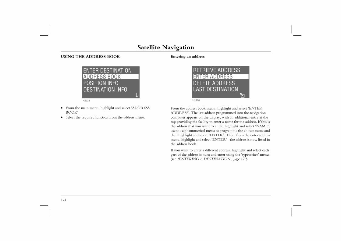
Satellite NavigationUSING THE ADDRESS BOOK Entering an address
book menu, highlight and select ‘ENTER last address programmed into the navigation on the display, with an additional entry at the facility to enter a name for the address. If this is u want to enter, highlight and select ‘NAME’; rical menu to programme the chosen name and select ‘ENTER’. Then, from the enter address
nd select ‘ENTER’ - the address is now listed in
ter a different address, highlight and select each in turn and enter using the ‘typewriter’ menu A DESTINATION’, page 170).
TER ADDRESSTRIEVE ADDRESS
8
LETE ADDRESSST DESTINATION
174
• From the main menu, highlight and select ‘ADDRESS BOOK’
• Select the required function from the address menu.
From the address ADDRESS’. Thecomputer appearstop providing the the address that youse the alphanumethen highlight andmenu, highlight athe address book.
If you want to enpart of the address(see ‘ENTERING
ADDRESS BOOKPOSITION INFODESTINATION INFO
ENTER DESTINATION
H2923
ENRE
H292
DELA
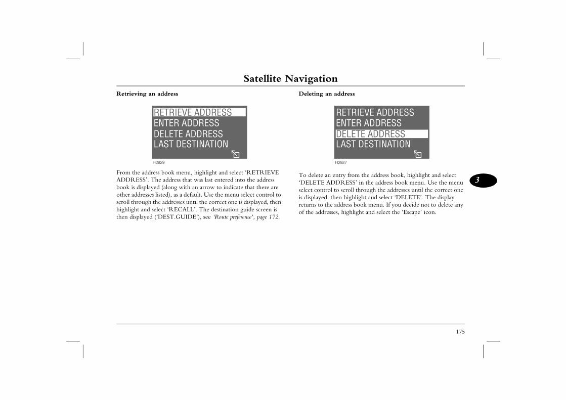
Satellite Navigation
175
3
n address
entry from the address book, highlight and select DDRESS’ in the address book menu. Use the menu l to scroll through the addresses until the correct one
then highlight and select ‘DELETE’. The display e address book menu. If you decide not to delete any sses, highlight and select the ‘Escape’ icon.
ENTER ADDRESSRETRIEVE ADDRESS
H2927
DELETE ADDRESSLAST DESTINATION
Retrieving an address
From the address book menu, highlight and select ‘RETRIEVE ADDRESS’. The address that was last entered into the address book is displayed (along with an arrow to indicate that there are other addresses listed), as a default. Use the menu select control to scroll through the addresses until the correct one is displayed, then highlight and select ‘RECALL’. The destination guide screen is then displayed (‘DEST.GUIDE’), see ‘Route preference’, page 172.
Deleting a
To delete an‘DELETE Aselect controis displayed,returns to thof the addre
ENTER ADDRESSRETRIEVE ADDRESS
H2929
DELETE ADDRESSLAST DESTINATION
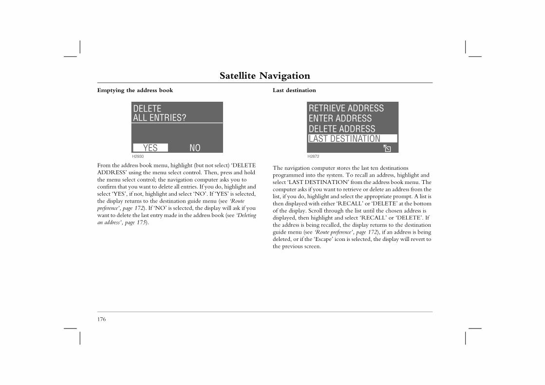
Satellite NavigationEmptying the address book Last destination
mputer stores the last ten destinations the system. To recall an address, highlight and TINATION’ from the address book menu. The ou want to retrieve or delete an address from the light and select the appropriate prompt. A list is
h either ‘RECALL’ or ‘DELETE’ at the bottom oll through the list until the chosen address is ghlight and select ‘RECALL’ or ‘DELETE’. If g recalled, the display returns to the destination Route preference’, page 172), if an address is being scape’ icon is selected, the display will revert to
n.
TER ADDRESSTRIEVE ADDRESS
2
LETE ADDRESSST DESTINATION
176
From the address book menu, highlight (but not select) ‘DELETE ADDRESS’ using the menu select control. Then, press and hold the menu select control; the navigation computer asks you to confirm that you want to delete all entries. If you do, highlight and select ‘YES’, if not, highlight and select ‘NO’. If ‘YES’ is selected, the display returns to the destination guide menu (see ‘Route preference’, page 172). If ‘NO’ is selected, the display will ask if you want to delete the last entry made in the address book (see ‘Deleting an address’, page 175).
The navigation coprogrammed intoselect ‘LAST DEScomputer asks if ylist, if you do, highthen displayed witof the display. Scrdisplayed, then hithe address is beinguide menu (see ‘deleted, or if the ‘Ethe previous scree
ALL ENTRIES?DELETE
H2930
YES NO
ENRE
H287
DELA
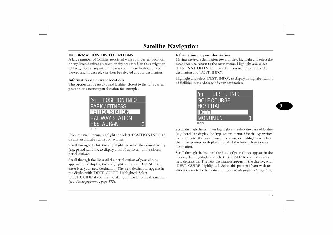
Satellite Navigation
177
3
n on your destinationred a destination town or city, highlight and select the to return to the main menu. Highlight and select TION INFO’ from the main menu to display the and ‘DEST. INFO’.
d select ‘DEST. INFO’, to display an alphabetical list n the vicinity of your destination.
gh the list, then highlight and select the desired facility to display the ‘typewriter’ menu. Use the typewriter ter the hotel name, if known, or highlight and select ompt to display a list of all the hotels close to your
gh the list until the hotel of your choice appears in the highlight and select ‘RECALL’ to enter it as your
tion. The new destination appears in the display, with IDE’ highlighted. Select this prompt if you wish to ute to the destination (see ‘Route preference’, page 172).
HOSPITALGOLF COURSE
DEST . INFO
MONUMENTH2924
HOTEL
INFORMATION ON LOCATIONSA large number of facilities associated with your current location, or any listed destination town or city are stored on the navigation CD (e.g. hotels, airports, museums etc). These facilities can be viewed and, if desired, can then be selected as your destination.
Information on current locationsThis option can be used to find facilities closest to the car’s current position; the nearest petrol station for example.
From the main menu, highlight and select ‘POSITION INFO’ to display an alphabetical list of facilities.
Scroll through the list, then highlight and select the desired facility (e.g. petrol stations), to display a list of up to ten of the closest petrol stations.
Scroll through the list until the petrol station of your choice appears in the display, then highlight and select ‘RECALL’ to enter it as your new destination. The new destination appears in the display with ‘DEST. GUIDE’ highlighted. Select ‘DEST.GUIDE’ if you wish to alter your route to the destination (see ‘Route preference’, page 172).
InformatioHaving enteescape icon ‘DESTINAdestination
Highlight anof facilities i
Scroll throu(e.g. hotels)menu to enthe index prdestination.
Scroll throudisplay, thennew destina‘DEST. GUalter your ro
PARK / FITNESSPOSITION INFO
RAILWAY STATION
H2871
RESTAURANT
PETROL STATION
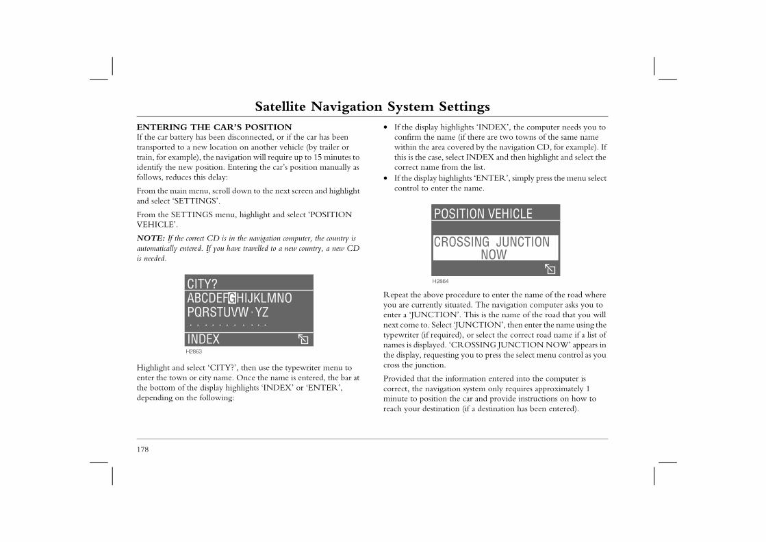
Satellite Navigation System SettingsSatellite Navigation System SettingsENTERING THE CAR’S POSITIONIf the car battery has been disconnected, or if the car has been transported to a new location on another vehicle (by trailer or
• If the display highlights ‘INDEX’, the computer needs you to confirm the name (if there are two towns of the same name within the area covered by the navigation CD, for example). If
select INDEX and then highlight and select the rom the list.ghlights ‘ENTER’, simply press the menu select r the name.
procedure to enter the name of the road where situated. The navigation computer asks you to
N’. This is the name of the road that you will ct ‘JUNCTION’, then enter the name using the ired), or select the correct road name if a list of . ‘CROSSING JUNCTION NOW’ appears in ting you to press the select menu control as you .
information entered into the computer is ation system only requires approximately 1 the car and provide instructions on how to tion (if a destination has been entered).
OSSING JUNCTION NOW
SITION VEHICLE
4
178
train, for example), the navigation will require up to 15 minutes to identify the new position. Entering the car’s position manually as follows, reduces this delay:
From the main menu, scroll down to the next screen and highlight and select ‘SETTINGS’.
From the SETTINGS menu, highlight and select ‘POSITION VEHICLE’.
NOTE: If the correct CD is in the navigation computer, the country is automatically entered. If you have travelled to a new country, a new CD is needed.
Highlight and select ‘CITY?’, then use the typewriter menu to enter the town or city name. Once the name is entered, the bar at the bottom of the display highlights ‘INDEX’ or ‘ENTER’, depending on the following:
this is the case,correct name f
• If the display hicontrol to ente
Repeat the aboveyou are currently enter a ‘JUNCTIOnext come to. Seletypewriter (if requnames is displayedthe display, requescross the junction
Provided that the correct, the navigminute to positionreach your destina
ABCDEFGHIJKLMNOHIJKLMNOABCDEFPQRSTUVW YZ
INDEX
CITY?
H2863
CR
PO
H286
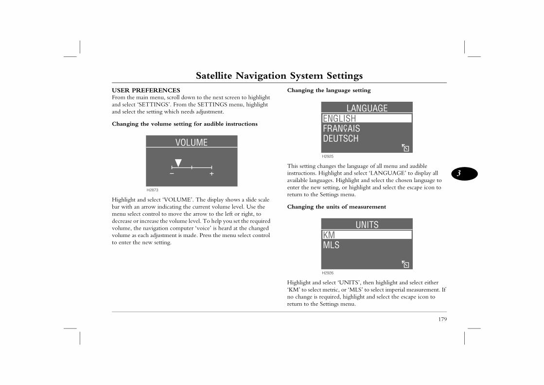
Satellite Navigation System Settings
179
3
the language setting
changes the language of all menu and audible . Highlight and select ‘LANGUAGE’ to display all guages. Highlight and select the chosen language to w setting, or highlight and select the escape icon to e Settings menu.
the units of measurement
d select ‘UNITS’, then highlight and select either ct metric, or ‘MLS’ to select imperial measurement. If s required, highlight and select the escape icon to e Settings menu.
FRAN AIS
LANGUAGE
H2925
ENGLISH
DEUTSCH
MLS
UNITS
H2926
KM
USER PREFERENCESFrom the main menu, scroll down to the next screen to highlight and select ‘SETTINGS’. From the SETTINGS menu, highlight and select the setting which needs adjustment.
Changing the volume setting for audible instructions
Highlight and select ‘VOLUME’. The display shows a slide scale bar with an arrow indicating the current volume level. Use the menu select control to move the arrow to the left or right, to decrease or increase the volume level. To help you set the required volume, the navigation computer ‘voice’ is heard at the changed volume as each adjustment is made. Press the menu select control to enter the new setting.
Changing
This settinginstructionsavailable lanenter the nereturn to th
Changing
Highlight an‘KM’ to seleno change ireturn to th
VOLUME
H2873
Security CodeSecurity CodeSECURITY CODE INFORMATIONTo reduce the risk of theft, your audio unit was programmed with a four-digit security code before the car left the factory. Once
ENTERING THE SECURITY CODEIf power to the audio unit has been interrupted (car battery disconnected, for example), the code MUST be entered before the
ed. Enter the code as follows:
radio (‘CODE’ appears in the display, followed
tton 1 the required number of times to enter the code.tton 2 the required number of times to enter the the code.cess using pre-set buttons 3 and 4 to enter the
h digits of the code.ect code is displayed, press the control to
correct codes hare been entered, the first one hour time ces. During the delay period, ‘WAIT 1 H’ appears NOT switch off. At the end of the delay period,
in the display and you can then enter the correct code.
180
activated, this code prevents the unit from functioning if it is illegally removed from the car.
In addition, each unit is further protected by a time delay penalty system. If an incorrect code is entered:• CD32 audio: A one hour time delay is imposed after the third
and all subsequent code entry attempts.• Harmony & Symphony audio: A one minute time delay is
imposed after the first code entry attempt. Thereafter, the time delay doubles (2 min, 4 min, 8 min, etc.) with each failed attempt.
Your car was supplied with a Security Information card. This card contains a record of the four digit security code, as well as the audio unit's unique serial number. The serial number is also stamped into the metal side of the audio unit and, in the event of theft, would confirm proof of ownership.
It is VERY IMPORTANT that you keep a safe record of the security code and heed the following advice:• NEVER keep a record of the security code in the car.• If you lose your code number, contact an MG Rover dealer,
who will be able to obtain this information for you.
unit can be operat
CD32 audio• Switch on the
by ‘0000’).• Press pre-set bu
first digit of the• Press pre-set bu
second digit of• Repeat this pro
third and fourt• When the corr
store the code.
NOTE: If three indelay period commenin the display - DO‘CODE’ reappears
Security Code
181
3
Harmony and Symphony audio• Switch on the radio (‘CODE’ appears in the display). Press pre-
set button 1.• Press either the up or down tuning button until the first digit
of the security code appears in the display. Press pre-set 1 to store the first digit in the unit's memory.
• Use either tuning button to select the second digit of the code (until the correct digit appears in the display). Press pre-set 1 to store the second digit.
• Select the third digit, again using the tuning buttons (until the correct digit is displayed). Press pre-set 1 to store the third digit.
• Select the final digit (the display now shows the full four digit code). Press pre-set 1 to store the final digit.
If the correct code has been selected the radio will commence operating immediately.
NOTE: If an incorrect code has been entered, the first time delay period commences. During the delay period, ‘CODE WAIT’ appears in the display - DO NOT switch off. At the end of the delay period, ‘CODE’ reappears in the display and you can then enter the correct code. Remember; the time delay period doubles each time an incorrect code is entered.

4
Maintenance
184 Maintenance188 Bonnet Opening189 Engine Compartment192 Engine194 Cooling System196 Brakes198 Power Steering200 Battery203 Washers204 Wipers206 Tyres209 Cleaning & Vehicle Care212 Identification Numbers214 Parts & Accessories
MaintenanceMaintenanceMaintenanceROUTINE SERVICINGThe safety, reliability and performance of your car will depend
For example, a car subjected predominantly to short journey motoring, will consume more fuel, resulting in a more rapid deterioration of the engine oil. In this case, the service distance
ce more rapidly, reaching zero after the car has 19,000 or 20,000 km. Conversely, the driver of for long motorway journeys, driving carefully ed limit, may well find that the service distance ‘zero’ until the car has exceeded 24,150 km.
is not carried out (or the dealer fails to reset the e indicator, having reached zero, will then start to minus values, indicating the distance by which a
cludes a Service History section, which enables t of all the oil services and inspections that are car. This section of the book also provides a ler to record brake fluid and coolant changes, as of replacement airbag modules and seat belt pre-
r signs and stamps the book after each oil service
184
partly on how well it is maintained.
Maintenance is the owner's responsibility and you must ensure that owner maintenance operations, oil services, inspections and brake fluid and coolant changes are carried out when required and according to the manufacturer's recommendations.
Oil services and inspectionsThe service interval display in the instrument panel shows the next service type (Oil Service or Inspection) and the distance remaining before the next service is due. This display appears for 4 seconds every time the starter switch is initially turned to the second position.
The distance display commences at 24,150 km and progressively reduces in increments of 50 km as the car is driven, until zero is reached. The relevant service should be carried out after 12 months or as soon as the distance display shows zero (whichever is the sooner). After the completion of each service, the servicing dealer will reset the distance display to 24,150 km.
NOTE: Because the service interval display reduces in increments of 50 km, it is possible to undertake a short journey without triggering any movement from the display.
While the oil services and inspections have nominal distance and time-related intervals of 24,150 km or 12 months, by measuring fuel consumption the car’s monitoring system is also able to assess the owner’s driving style and the type of motoring to which the car is subjected. These additional factors will affect the point at which the service should be carried out.
indicator will redutravelled as few as a car used mainly and within the speindicator does not
NOTE: If a servicedisplay), the distancaccumulate, but withservice is overdue.
Service historyThis handbook ina record to be kepcarried out on thefacility for the deawell as the fitting tensioners.
Ensure your dealeand inspection.
Maintenance
185
4
CONTROLitted with emission and evaporative control equipment meet specific territorial and legal requirements. You are that unauthorised replacement, modification or ith this equipment by an owner or motor vehicle ld be unlawful and subject to legal penalties.
engine settings must not be tampered with. These stablished to ensure that your car complies with haust emission regulations. Incorrect engine settings ly affect exhaust emissions, engine performance and ption, as well as causing high temperatures, which in damage to the catalytic converters and engine.
Brake fluid replacementThe brake fluid requires replacement every two years, irrespective of the distance the car has travelled. Normally, the brake fluid change indicator on the instrument panel will commence illuminating (for four seconds every time the starter switch is initially turned to the second position) as soon as each two year period has elapsed (see ‘Service interval display (3)’, page 75). However, if an impending oil service or inspection falls due within a period of up to 180 days prior to the brake fluid change becoming due, then the indicator will illuminate earlier. This will enable the dealer to combine the brake fluid change with the oil service or inspection, thereby avoiding the need for an additional dealer visit.
NOTE: Brake fluid replacement will be an additional cost.
Coolant replacementThe engine coolant (anti-freeze and water solution) needs to be replaced every four years regardless of the distance the car has travelled. Your dealer will replace the coolant at the scheduled oil service or inspection nearest to the conclusion of each four year period, to avoid the need for an additional dealer visit.
NOTE: Coolant replacement will be an additional cost.
EMISSIONYour car is fdesigned to should be awtampering wrepairer cou
In addition,have been estringent exmay adversefuel consumcould result
MaintenanceOWNER MAINTENANCEIn addition to the routine services and inspections referred to previously, a number of simple checks must be carried out more
SPECIAL OPERATING CONDITIONSIf your car is frequently used in dusty conditions, or operated in extreme climates where sub-zero or very high ambient
ormal, more frequent attention may need to be equirements. Contact an MG Rover dealer for
186
frequently. You can carry out these checks yourself and advice is given on the pages that follow.
Any significant or sudden drop in fluid levels, or uneven tyre wear, should be reported to a dealer without delay.
Daily checks• Operation of lights, horn, direction indicators, wipers, washers
and warning lights.• Operation of seat belts and brakes.• Look for fluid deposits underneath the car that might indicate
a leak.
Weekly checks• Engine oil level.
NOTE: The engine oil level should be checked more frequently if the car is driven for prolonged periods at high speeds.
• Coolant level.• Brake fluid level.• Power steering fluid level.• Screen washer fluid level.• Tyre pressures and condition.• Operate air conditioning*.
temperatures are npaid to servicing radvice.
Maintenance
187
4
fluids
gal to pollute drains, water courses or soil. Use authorised isposal sites to dispose of used oil and toxic chemicals.
in motor vehicles are poisonous and should not be r brought into contact with open wounds. These tery acid, anti-freeze, brake and power steering fluid, l, engine oil and windscreen washer additives.
n safety, ALWAYS read and obey all instructions abels and containers.
e oilontact with engine oil may cause serious skin cluding dermatitis and cancer of the skin. Wash after contact.
SAFETY IN THE GARAGE
Cooling fans may commence operating after the engine is switched off, and continue operating for a number of minutes.
Keep clear of all fans while working in the engine compartment.
If you need to carry out maintenance, observe the following safety precautions at all times:• Keep your hands and clothing away from drive belts and
pulleys.• If the car has been driven recently, DO NOT TOUCH
exhaust and cooling system components until the engine has cooled.
• DO NOT TOUCH electrical leads or components while the engine is running, or with the starter switch turned on.
• NEVER leave the engine running in an unventilated area - exhaust gases are poisonous and extremely dangerous.
• DO NOT work underneath the car with a wheel changing jack as the only means of support.
• Ensure sparks and naked lights are kept away from the engine compartment.
• Wear protective clothing, including, where practicable, gloves made from an impervious material.
• Remove metal wrist bands and jewellery before working in the engine compartment.
• DO NOT allow tools or metal parts of the car to make contact with the battery leads or terminals.
Poisonous
It is illewaste d
Fluids used consumed oinclude: batpetrol, diese
For your owprinted on l
Used enginProlonged cdisorders, inthoroughly
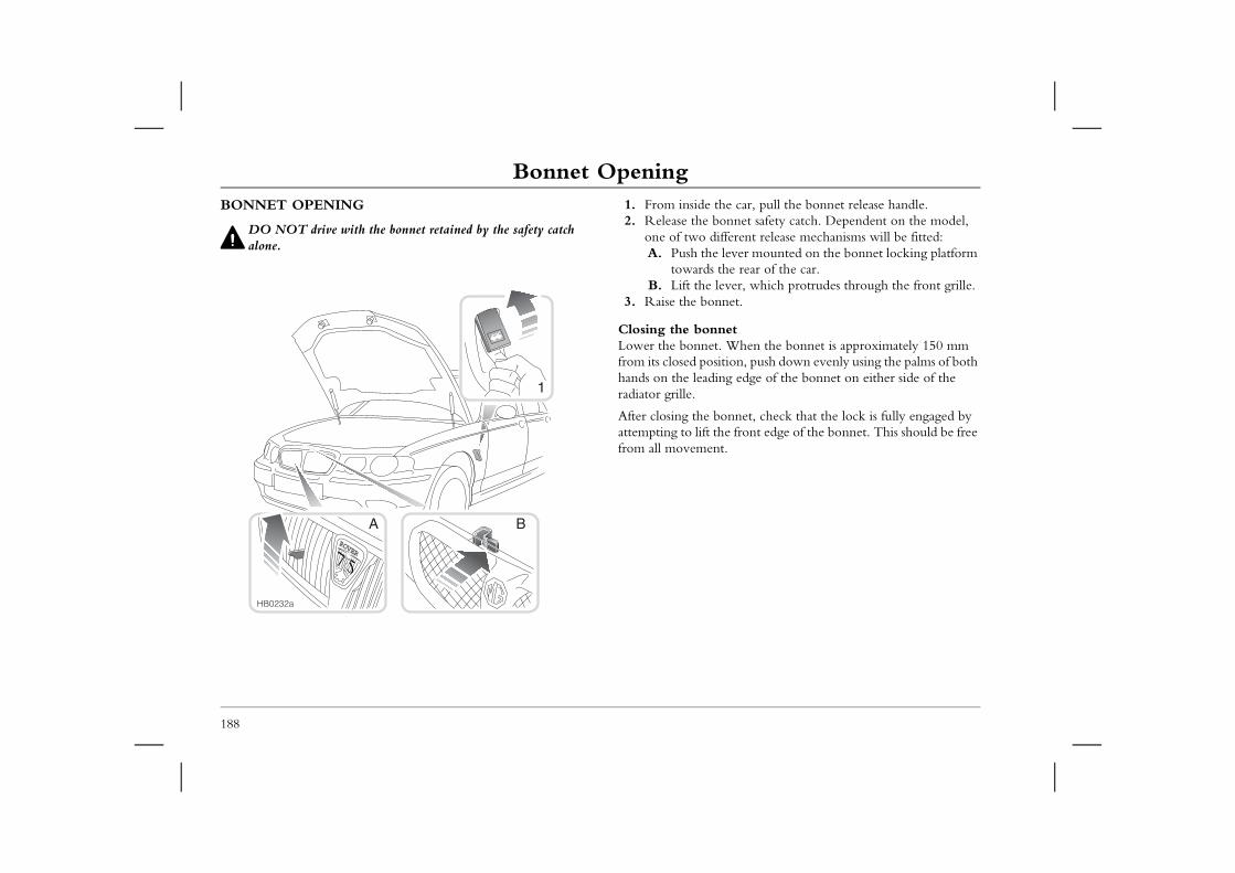
Bonnet OpeningBonnet OpeningBONNET OPENING
DO NOT drive with the bonnet retained by the safety catch
1. From inside the car, pull the bonnet release handle.2. Release the bonnet safety catch. Dependent on the model,
one of two different release mechanisms will be fitted: lever mounted on the bonnet locking platform the rear of the car.lever, which protrudes through the front grille.net.
net. When the bonnet is approximately 150 mm ition, push down evenly using the palms of both ng edge of the bonnet on either side of the
onnet, check that the lock is fully engaged by he front edge of the bonnet. This should be free t.
188
alone. A. Push thetowards
B. Lift the 3. Raise the bon
Closing the bonLower the bonnetfrom its closed poshands on the leadiradiator grille.
After closing the battempting to lift tfrom all movemen
ROVER
1
A B
HB0232a
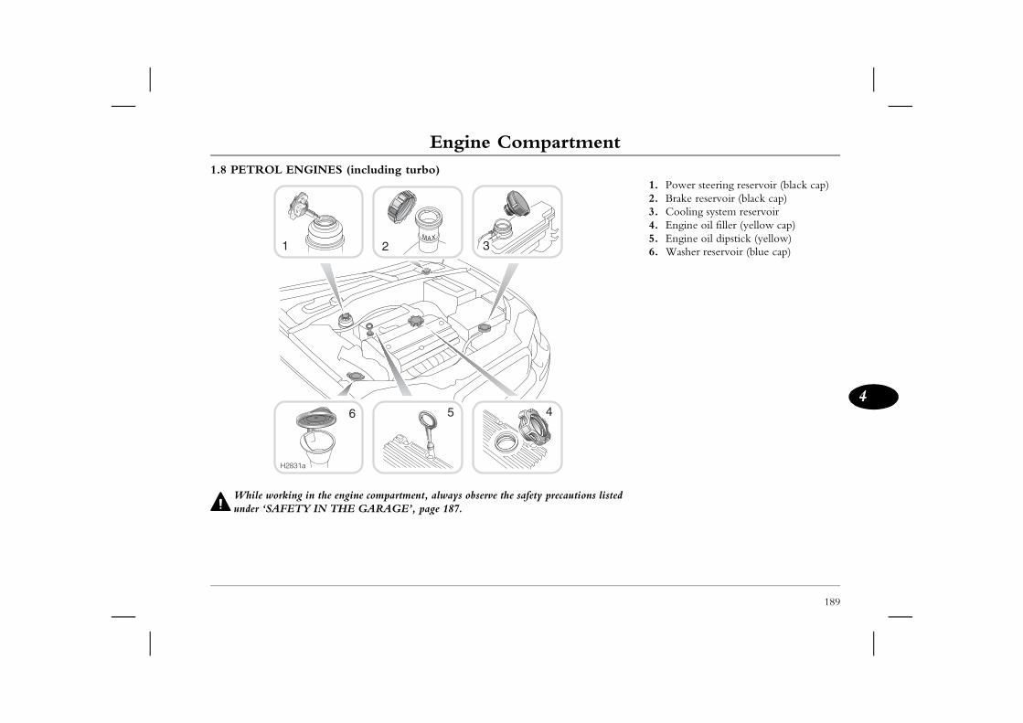
189
Engine Compartment
4
Engine Compartment
listed
1. Power steering reservoir (black cap)2. Brake reservoir (black cap)3. Cooling system reservoir4. Engine oil filler (yellow cap)5. Engine oil dipstick (yellow)6. Washer reservoir (blue cap)
While working in the engine compartment, always observe the safety precautionsunder ‘SAFETY IN THE GARAGE’, page 187.
H2831a
456
1.8 PETROL ENGINES (including turbo)
1 2 3
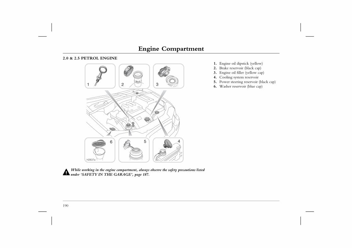
Engine Compartment2.0 & 2.5 PETROL ENGINE
1. Engine oil dipstick (yellow)2. Brake reservoir (black cap)3. Engine oil filler (yellow cap)4. Cooling system reservoir5. Power steering reservoir (black cap)6. Washer reservoir (blue cap)
190
While working in the engine compartment, always observe the safety precautions listedunder ‘SAFETY IN THE GARAGE’, page 187.
H2837a
456
1 2 3
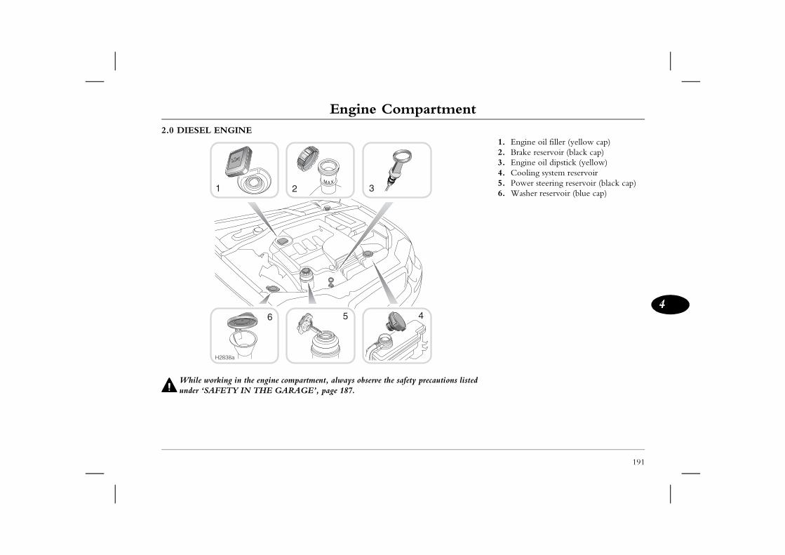
191
Engine Compartment
4
listed
1. Engine oil filler (yellow cap)2. Brake reservoir (black cap)3. Engine oil dipstick (yellow)4. Cooling system reservoir5. Power steering reservoir (black cap)6. Washer reservoir (blue cap)
While working in the engine compartment, always observe the safety precautionsunder ‘SAFETY IN THE GARAGE’, page 187.
H2838a
456
2.0 DIESEL ENGINE
1 2 3
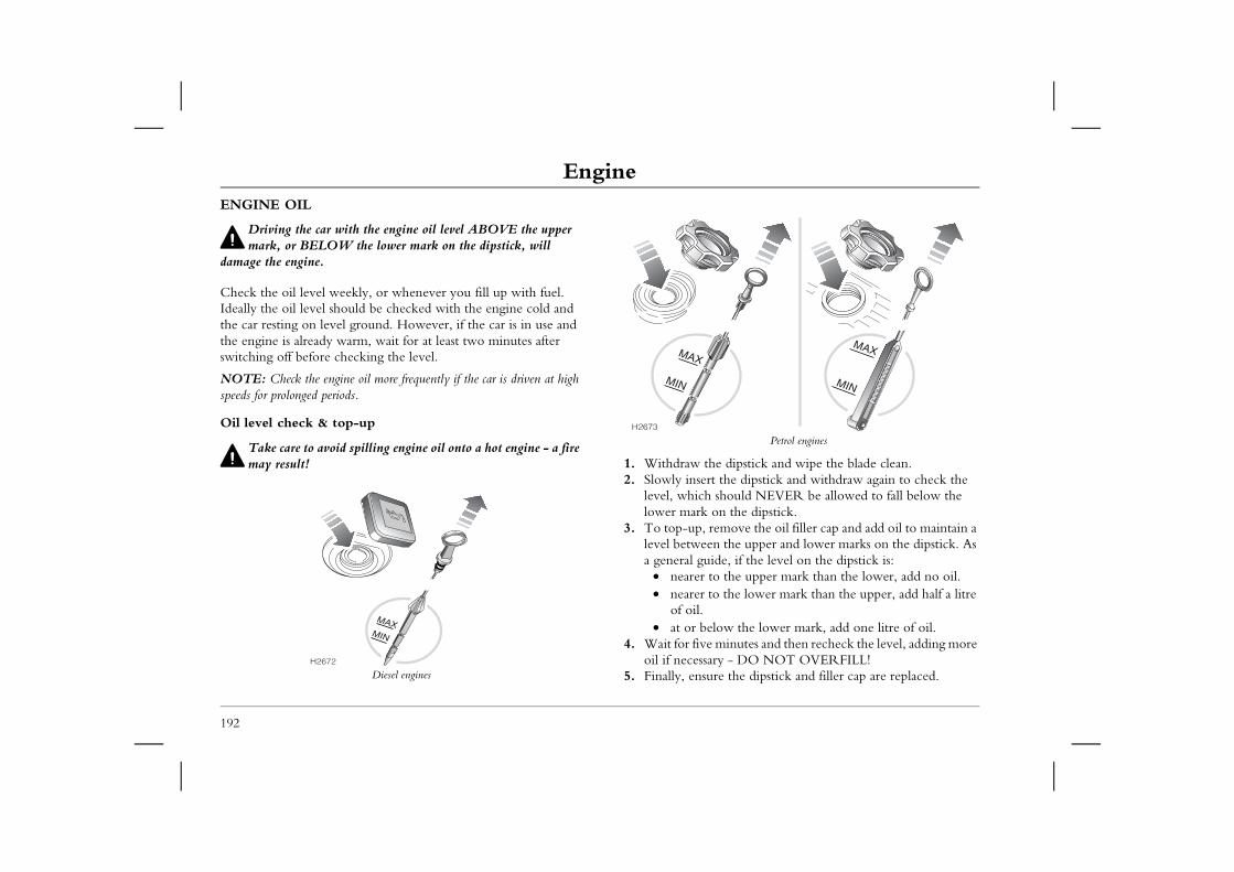
EngineEngineENGINE OIL
Driving the car with the engine oil level ABOVE the upper
Petrol engines
e dipstick and wipe the blade clean. the dipstick and withdraw again to check the should NEVER be allowed to fall below the n the dipstick.move the oil filler cap and add oil to maintain a the upper and lower marks on the dipstick. As
de, if the level on the dipstick is: the upper mark than the lower, add no oil. the lower mark than the upper, add half a litre
ow the lower mark, add one litre of oil.minutes and then recheck the level, adding more y - DO NOT OVERFILL! e the dipstick and filler cap are replaced.
MIN
MAX
192
mark, or BELOW the lower mark on the dipstick, will damage the engine.
Check the oil level weekly, or whenever you fill up with fuel. Ideally the oil level should be checked with the engine cold and the car resting on level ground. However, if the car is in use and the engine is already warm, wait for at least two minutes after switching off before checking the level.
NOTE: Check the engine oil more frequently if the car is driven at high speeds for prolonged periods.
Oil level check & top-up
Take care to avoid spilling engine oil onto a hot engine - a fire may result!
Diesel engines
1. Withdraw th2. Slowly insert
level, which lower mark o
3. To top-up, relevel betweena general gui
• nearer to• nearer to
of oil.• at or bel
4. Wait for five oil if necessar
5. Finally, ensurH2672
MIN
MAX
H2673
MIN
MAX
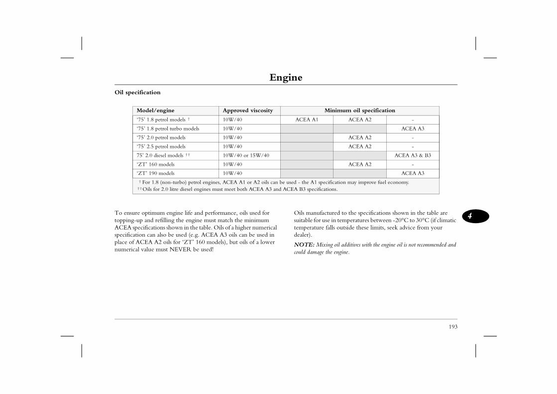
Engine
193
4ctured to the specifications shown in the table are se in temperatures between -20°C to 30°C (if climatic falls outside these limits, seek advice from your
xing oil additives with the engine oil is not recommended and the engine.
Minimum oil specification
ACEA A2 -
ACEA A3
ACEA A2 -
ACEA A2 -
ACEA A3 & B3
ACEA A2 -
ACEA A3
ecification may improve fuel economy.ations.
Oil specification
To ensure optimum engine life and performance, oils used for topping-up and refilling the engine must match the minimum ACEA specifications shown in the table. Oils of a higher numerical specification can also be used (e.g. ACEA A3 oils can be used in place of ACEA A2 oils for ‘ZT’ 160 models), but oils of a lower numerical value must NEVER be used!
Oils manufasuitable for utemperaturedealer).
NOTE: Micould damage
Model/engine Approved viscosity
‘75’ 1.8 petrol models † 10W/40 ACEA A1
‘75’ 1.8 petrol turbo models 10W/40
‘75’ 2.0 petrol models 10W/40
‘75’ 2.5 petrol models 10W/40
75’ 2.0 diesel models † † 10W/40 or 15W/40
‘ZT’ 160 models 10W/40
‘ZT’ 190 models 10W/40
† For 1.8 (non-turbo) petrol engines, ACEA A1 or A2 oils can be used - the A1 sp † † Oils for 2.0 litre diesel engines must meet both ACEA A3 and ACEA B3 specific

Cooling SystemCooling SystemCOOLANT CHECK & TOP-UP
DO NOT remove the reservoir cap when the cooling system is
If the level is below the ‘MAX’ mark, top-up with a 50% mix of water and ethylene glycol based anti-freeze (containing no methanol) with Organic Acid Technology (OAT) corrosion
g BTC coding type 4E.
ping-up, avoid spillage on body panels - anti-freeze surfaces.
l falls appreciably during a short period, suspect ting and arrange for your dealer to examine the
tightened fully after topping-up.
194
hot - escaping steam or water could cause serious injury.
The coolant level should be checked weekly when the cooling system is cold and with the car resting on level ground.
Remove the filler cap to check the level of the coolant. The level marking can only be viewed through the filler neck.
If it is necessary to remove the filler cap before the system has fully cooled, loosen the cap slowly, allowing the air pressure to escape gradually before removing the cap completely.
inhibitors, meetin
NOTE: When topwill damage painted
If the coolant leveleakage or overheacar.
Ensure the cap is
H2687
Cooling System
195
4
ANTI-FREEZE
Anti-freeze is poisonous and can be fatal if swallowed - keep containers sealed and out of the reach of children. If accidental
consumption is suspected, seek medical attention immediately.
Prevent anti-freeze coming into contact with the skin or eyes. If this occurs, rinse immediately with plenty of water.
The anti-freeze content of the coolant must be maintained between 50% and 60% all year round (not just in cold conditions). To ensure that the anti-corrosion properties of the coolant are retained, the anti-freeze content should be checked by your dealer once a year and the coolant completely renewed every four years, regardless of distance travelled.
NOTE: DO NOT add rust inhibitors or other additives to the coolant - these may not be compatible with the coolant or engine components.
Coolant specificationUse ONLY a 50% mix of water and Havoline Extended Life Coolant (XLC), or any ethylene glycol based anti-freeze (containing no methanol) with Organic Acid Technology (OAT) corrosion inhibitors, meeting BTC coding type 4E.
In an emergency - and only if this type of anti-freeze is unavailable - top-up the cooling system with clean water, but be aware of the resultant reduction in frost protection. DO NOT top-up or refill with other anti-freeze formulations. If in doubt, consult a dealer.
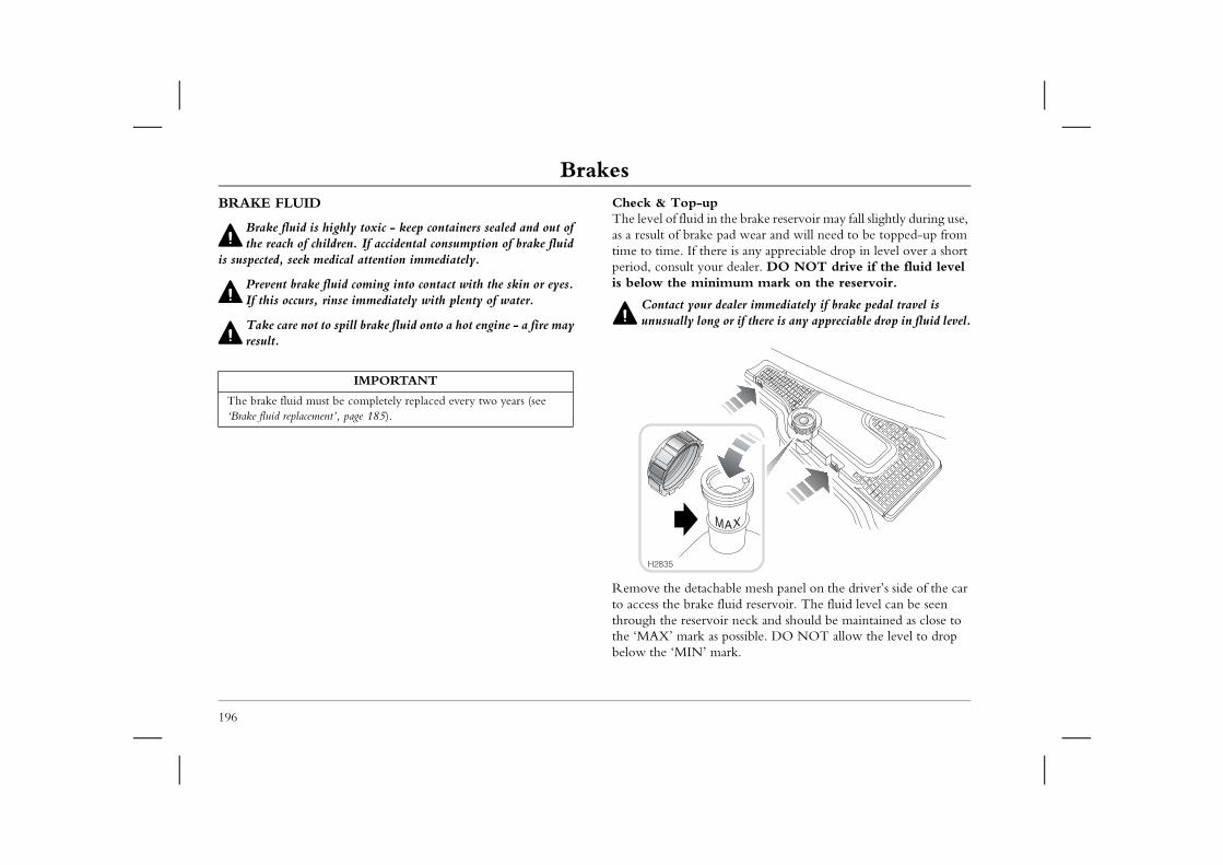
BrakesBrakesBRAKE FLUID
Brake fluid is highly toxic - keep containers sealed and out of
Check & Top-upThe level of fluid in the brake reservoir may fall slightly during use, as a result of brake pad wear and will need to be topped-up from
ere is any appreciable drop in level over a short ur dealer. DO NOT drive if the fluid level nimum mark on the reservoir.
dealer immediately if brake pedal travel is g or if there is any appreciable drop in fluid level.
hable mesh panel on the driver’s side of the car fluid reservoir. The fluid level can be seen oir neck and should be maintained as close to
as possible. DO NOT allow the level to drop mark.
196
the reach of children. If accidental consumption of brake fluid is suspected, seek medical attention immediately.
Prevent brake fluid coming into contact with the skin or eyes. If this occurs, rinse immediately with plenty of water.
Take care not to spill brake fluid onto a hot engine - a fire may result.
time to time. If thperiod, consult yois below the mi
Contact yourunusually lon
Remove the detacto access the brakethrough the reservthe ‘MAX’ mark below the ‘MIN’
IMPORTANT
The brake fluid must be completely replaced every two years (see ‘Brake fluid replacement’, page 185).
H2835
Brakes
197
4
Wipe the cap clean to prevent dirt from entering the reservoir. Unscrew the cap and top-up the reservoir to the ‘MAX’ mark using a recommended fluid.
NOTE: Brake fluid will damage painted surfaces. Soak up any spillage with an absorbent cloth immediately and wash the area with a mixture of car shampoo and water.
Use only new fluid from a sealed container (old fluid from uncapped containers or fluid previously bled from the system will have absorbed moisture and/or air, and adversely affect braking performance).
Brake fluid specificationAny proprietary brand of brake fluid (or brake and clutch fluid) meeting DOT 4 specification.
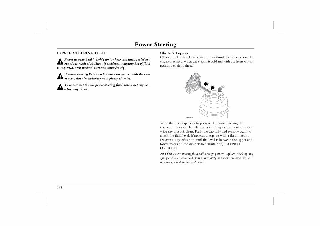
Power SteeringPower SteeringPOWER STEERING FLUID
Power steering fluid is highly toxic - keep containers sealed and
Check & Top-upCheck the fluid level every week. This should be done before the engine is started, when the system is cold and with the front wheels
head.
clean to prevent dirt from entering the e the filler cap and, using a clean lint-free cloth, clean. Refit the cap fully and remove again to el. If necessary, top-up with a fluid meeting cation until the level is between the upper and e dipstick (see illustration). DO NOT
ring fluid will damage painted surfaces. Soak up any rbent cloth immediately and wash the area with a
poo and water.
H2683
198
out of the reach of children. If accidental consumption of fluid is suspected, seek medical attention immediately.
If power steering fluid should come into contact with the skin or eyes, rinse immediately with plenty of water.
Take care not to spill power steering fluid onto a hot engine - a fire may result.
pointing straight a
Wipe the filler capreservoir. Removwipe the dipstick check the fluid levDexron III specifilower marks on thOVERFILL!
NOTE: Power steespillage with an absomixture of car sham
Power Steering
199
4
Fluid specificationUse any fluid to Dexron III specification. Fluids manufactured to this specification are suitable for use in temperatures between -20°C to +30°C (if climatic temperature falls outside these limits, seek advice from your dealer).
NOTE: The colour of commercially available power steering fluids may differ from that used to fill the system during manufacture. This is not a cause for concern.
Emergency operationAny frequent or regular need to top-up the fluid should be investigated by a qualified dealer.
Under no circumstances should the car be driven with the fluid level below the lower mark on the dipstick, or if a rapid or significant loss of fluid is detected. However, if it can be established that fluid loss is slow, then the reservoir may be topped-up to the upper level mark to enable the car to be driven a short distance to the nearest dealer for examination.
If the fluid has dropped below the lower level mark, top-up the reservoir BEFORE starting the engine, or damage to the steering pump could result.
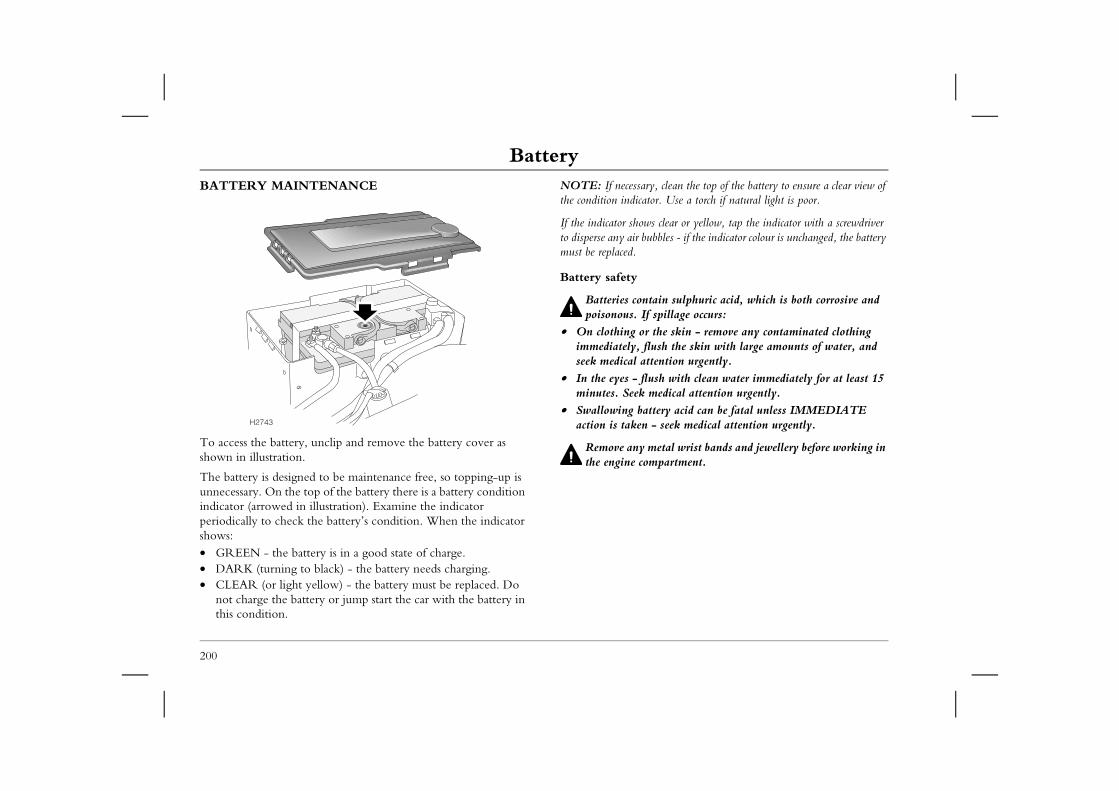
BatteryBatteryBATTERY MAINTENANCE NOTE: If necessary, clean the top of the battery to ensure a clear view of
the condition indicator. Use a torch if natural light is poor.
s clear or yellow, tap the indicator with a screwdriver bbles - if the indicator colour is unchanged, the battery
tain sulphuric acid, which is both corrosive and spillage occurs: the skin - remove any contaminated clothing ush the skin with large amounts of water, and tention urgently.ush with clean water immediately for at least 15 medical attention urgently.ttery acid can be fatal unless IMMEDIATE - seek medical attention urgently.
etal wrist bands and jewellery before working in mpartment.
200
To access the battery, unclip and remove the battery cover as shown in illustration.
The battery is designed to be maintenance free, so topping-up is unnecessary. On the top of the battery there is a battery condition indicator (arrowed in illustration). Examine the indicator periodically to check the battery’s condition. When the indicator shows:• GREEN - the battery is in a good state of charge.• DARK (turning to black) - the battery needs charging.• CLEAR (or light yellow) - the battery must be replaced. Do
not charge the battery or jump start the car with the battery in this condition.
If the indicator showto disperse any air bumust be replaced.
Battery safety
Batteries conpoisonous. If
• On clothing orimmediately, flseek medical at
• In the eyes - flminutes. Seek
• Swallowing baaction is taken
Remove any mthe engine co
H2743
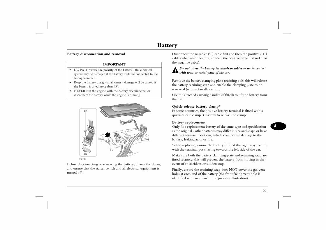
Battery
201
4
the negative (‘-’) cable first and then the positive (‘+’) reconnecting, connect the positive cable first and then cable).
allow the battery terminals or cables to make contact ols or metal parts of the car.
battery clamping plate retaining bolt; this will release retaining strap and enable the clamping plate to be e inset in illustration).
ched carrying handles (if fitted) to lift the battery from
ase battery clamp*ntries, the positive battery terminal is fitted with a e clamp. Unscrew to release the clamp.
lacementplacement battery of the same type and specification al - other batteries may differ in size and shape or have minal positions, which could cause damage to the ing acid, or fire.
cing, ensure the battery is fitted the right way round, minal posts facing towards the left side of the car.
oth the battery clamping plate and retaining strap are ly; this will prevent the battery from moving in the accident or sudden stop.
re the retaining strap does NOT cover the gas vent h end of the battery (the front facing vent hole is ith an arrow in the previous illustration).
Battery disconnection and removal
Before disconnecting or removing the battery, disarm the alarm, and ensure that the starter switch and all electrical equipment is turned off.
Disconnect cable (whenthe negative
Do notwith to
Remove thethe battery removed (se
Use the attathe car.
Quick-releIn some couquick-releas
Battery repOnly fit a reas the origindifferent terbattery, leak
When replawith the ter
Make sure bfitted secureevent of an
Finally, ensuholes at eacidentified w
IMPORTANT
• DO NOT reverse the polarity of the battery - the electrical system may be damaged if the battery leads are connected to the wrong terminals.
• Keep the battery upright at all times - damage will be caused if the battery is tilted more than 45°.
• NEVER run the engine with the battery disconnected, or disconnect the battery while the engine is running.
H2787
BatteryBattery disposal
Used batteries are hazardous to the environment, and should be
• Keep the area around the top of the battery well ventilated.• Do not allow naked lights near the battery (batteries generate
drogen during and after charging).ll be charged sufficiently once the battery ator shows GREEN. When charging is finished, attery charger BEFORE disconnecting the leads y terminals.
ttery will take longer to charge in a cold environment.
ve the battery for one hour before reconnection ill allow time for explosive gases to disperse, g the risk of fire or explosion.
202
recycled. If in doubt seek advice about disposal from an MG Rover dealer or your local authority.
Battery charging
DO NOT charge the battery if it is connected to the car - this may seriously damage the car's electrical system.
DO NOT attempt to charge the battery if the battery condition indicator is clear or light yellow.
DO NOT charge the battery if it is suspected of being frozen.
As the battery ages, it may not retain its charge as effectively as when it was new. Cars that are used infrequently, or are used excessively for short journey motoring, or operation in cold climates, may need the battery to be charged regularly.
Always check the battery condition indicator before charging.
Batteries generate explosive gases, contain corrosive acid and produce levels of electric current sufficient to cause serious injury. While charging, always heed the following precautions: • Before charging, disconnect and remove the battery from the
car - charging the battery with the cables connected may damage the car’s electrical system.
• Make sure the battery charger leads are securely clamped to the battery terminals BEFORE switching on the battery charger. Do not move the leads once the charger is switched on.
• While charging, shield your eyes, or avoid leaning over the battery.
inflammable hy• The battery wi
condition indicswitch off the bfrom the batter
NOTE: The ba
After charging, leato the car - this wthereby minimisin
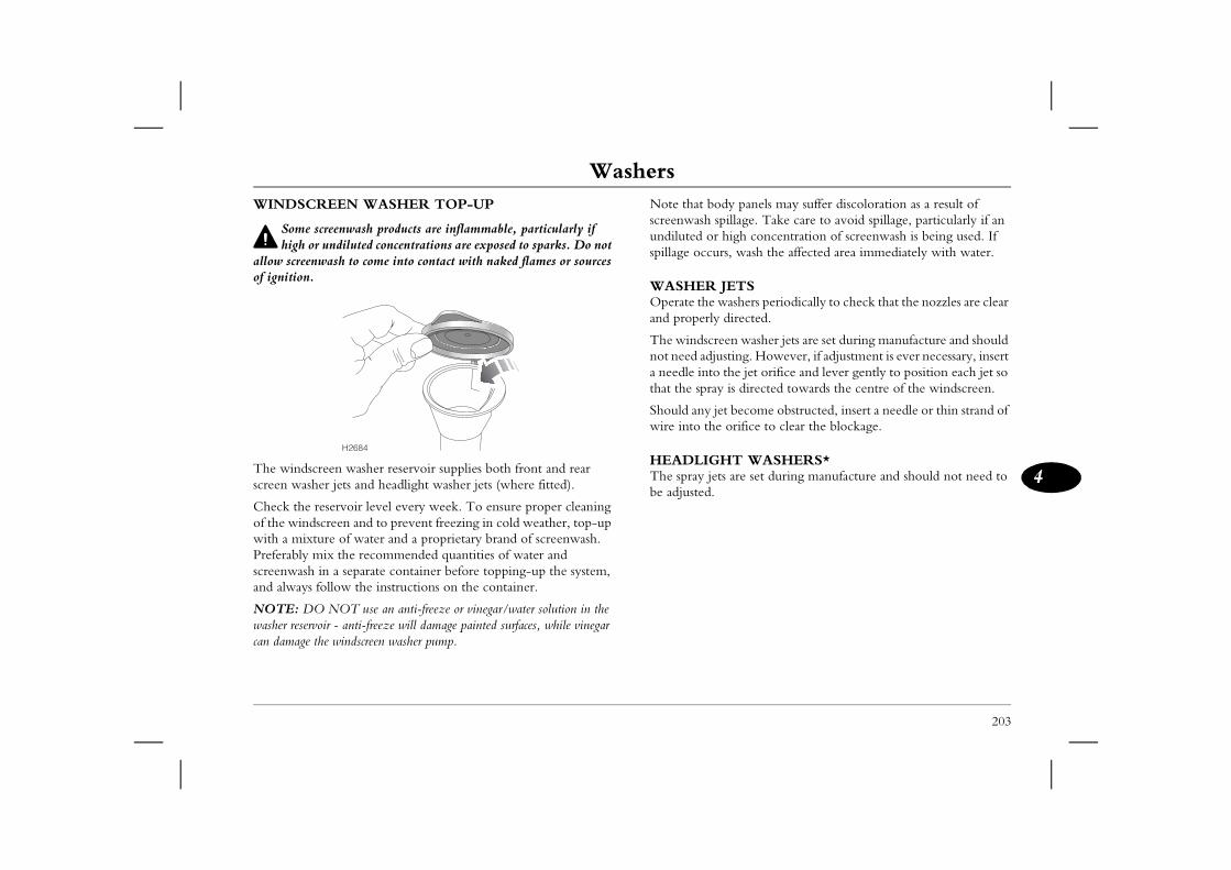
Washers
203
4
Washers ody panels may suffer discoloration as a result of spillage. Take care to avoid spillage, particularly if an r high concentration of screenwash is being used. If rs, wash the affected area immediately with water.
JETS washers periodically to check that the nozzles are clear y directed.
reen washer jets are set during manufacture and should usting. However, if adjustment is ever necessary, insert o the jet orifice and lever gently to position each jet so y is directed towards the centre of the windscreen.
jet become obstructed, insert a needle or thin strand of e orifice to clear the blockage.
HT WASHERS*ts are set during manufacture and should not need to
WINDSCREEN WASHER TOP-UP
Some screenwash products are inflammable, particularly if high or undiluted concentrations are exposed to sparks. Do not
allow screenwash to come into contact with naked flames or sources of ignition.
The windscreen washer reservoir supplies both front and rear screen washer jets and headlight washer jets (where fitted).
Check the reservoir level every week. To ensure proper cleaning of the windscreen and to prevent freezing in cold weather, top-up with a mixture of water and a proprietary brand of screenwash. Preferably mix the recommended quantities of water and screenwash in a separate container before topping-up the system, and always follow the instructions on the container.
NOTE: DO NOT use an anti-freeze or vinegar/water solution in the washer reservoir - anti-freeze will damage painted surfaces, while vinegar can damage the windscreen washer pump.
Note that bscreenwash undiluted ospillage occu
WASHEROperate theand properl
The windscnot need adja needle intthat the spra
Should any wire into th
HEADLIGThe spray jebe adjusted.
H2684
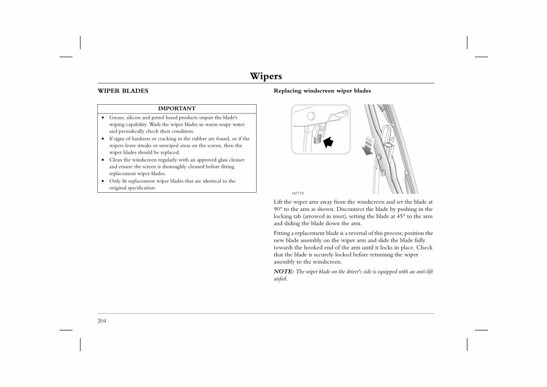
WipersWipersWIPER BLADES Replacing windscreen wiper blades
away from the windscreen and set the blade at shown. Disconnect the blade by pushing in the ed in inset), setting the blade at 45° to the arm de down the arm.
ent blade is a reversal of this process; position the ly on the wiper arm and slide the blade fully ed end of the arm until it locks in place. Check curely locked before returning the wiper indscreen.
blade on the driver's side is equipped with an anti-lift
204
Lift the wiper arm90° to the arm as locking tab (arrowand sliding the bla
Fitting a replacemnew blade assembtowards the hookthat the blade is seassembly to the w
NOTE: The wiperairfoil.
IMPORTANT
• Grease, silicon and petrol based products impair the blade's wiping capability. Wash the wiper blades in warm soapy water and periodically check their condition.
• If signs of hardness or cracking in the rubber are found, or if the wipers leave streaks or unwiped areas on the screen, then the wiper blades should be replaced.
• Clean the windscreen regularly with an approved glass cleaner and ensure the screen is thoroughly cleaned before fitting replacement wiper blades.
• Only fit replacement wiper blades that are identical to the original specification.
H2719
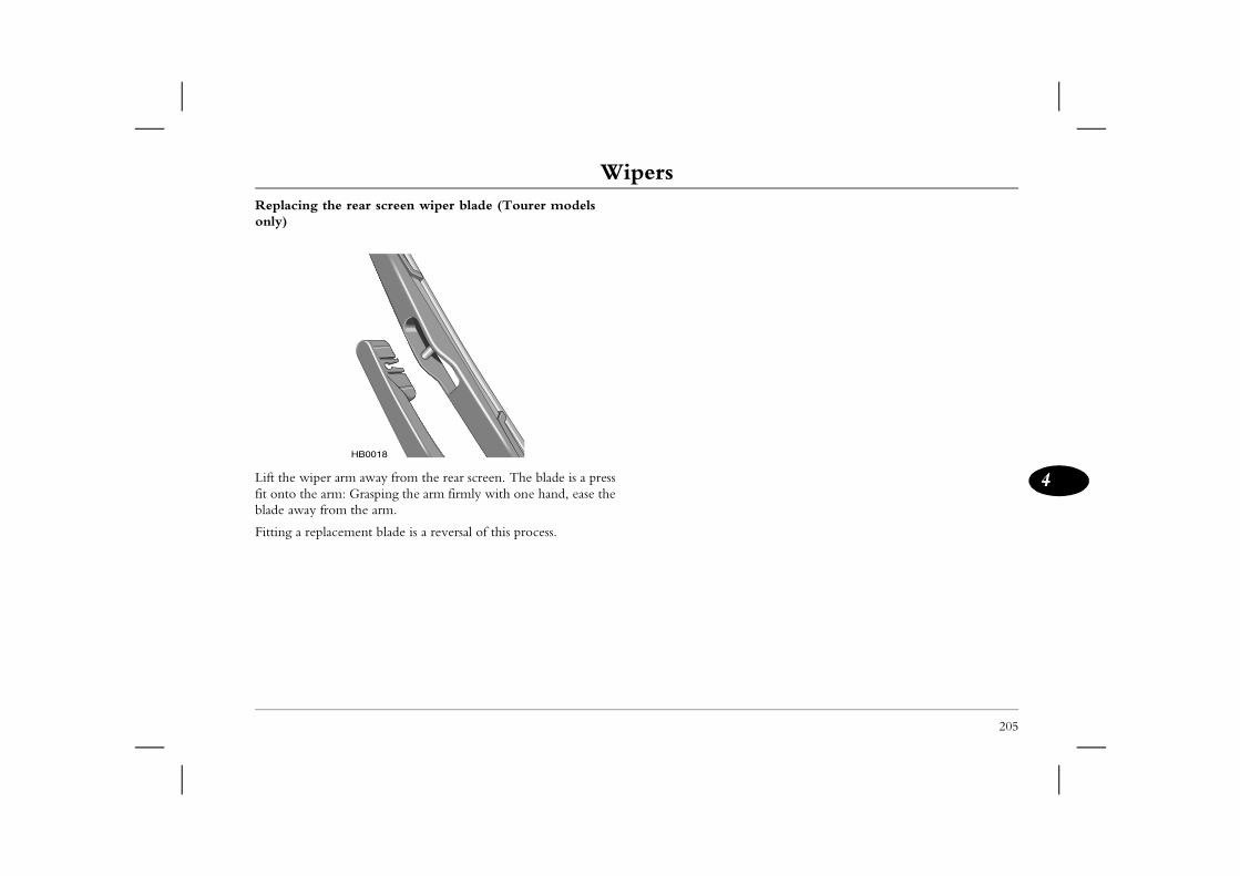
Wipers
205
4
Replacing the rear screen wiper blade (Tourer models only)
Lift the wiper arm away from the rear screen. The blade is a press fit onto the arm: Grasping the arm firmly with one hand, ease the blade away from the arm.
Fitting a replacement blade is a reversal of this process.
HB0018
TyresTyresCARING FOR YOUR TYRES
DEFECTIVE TYRES ARE DANGEROUS! Do not drive
Tyre pressuresCorrectly inflated tyres will ensure that you enjoy the best combination of tyre life, ride comfort, fuel economy and road
es wear more rapidly, can seriously affect the characteristics and fuel consumption, as well as
of tyre failure. Over-inflated tyres give a harsher ly and are more prone to damage.
es (including the spare wheel) at least every yres are cold - be aware that it only takes km of driving to warm up the tyres sufficiently ressures.
ally increases in warm tyres; if it is necessary to en they are warm (after the car has been driven hould expect the pressures to have increased .4 bar. In this circumstance, NEVER let air out er to match the recommended pressures.
ded pressures for cold tyres, see ‘TYRE ge 260.
s screwed down firmly - they prevent dirt from . Check the valve for leaks (listen for a tell-tale check the tyre pressure.
206
if any tyre is damaged, is excessively worn, or is inflated to an incorrect pressure.
Always drive with consideration for the condition of the tyres, and regularly inspect the tread and side walls for any sign of distortion (bulges), cuts or wear.
The most common causes of tyre failure are:• Bumping against kerbs• Driving over deep potholes in the road• Driving with under or over-inflated tyres
NOTE: If possible, protect tyres from contamination by oil, grease, fuel and other automotive fluids.
handling.
Under-inflated tyrcar’s road handlingincreasing the riskride, wear uneven
Check the pressurweek, when the tapproximately 1.6to affect the tyre p
Air pressure naturcheck the tyres whfor a while), you sbetween 0.3 and 0of the tyres in ord
For the recommenPRESSURES’, pa
ValvesKeep the valve capentering the valvehissing) when you
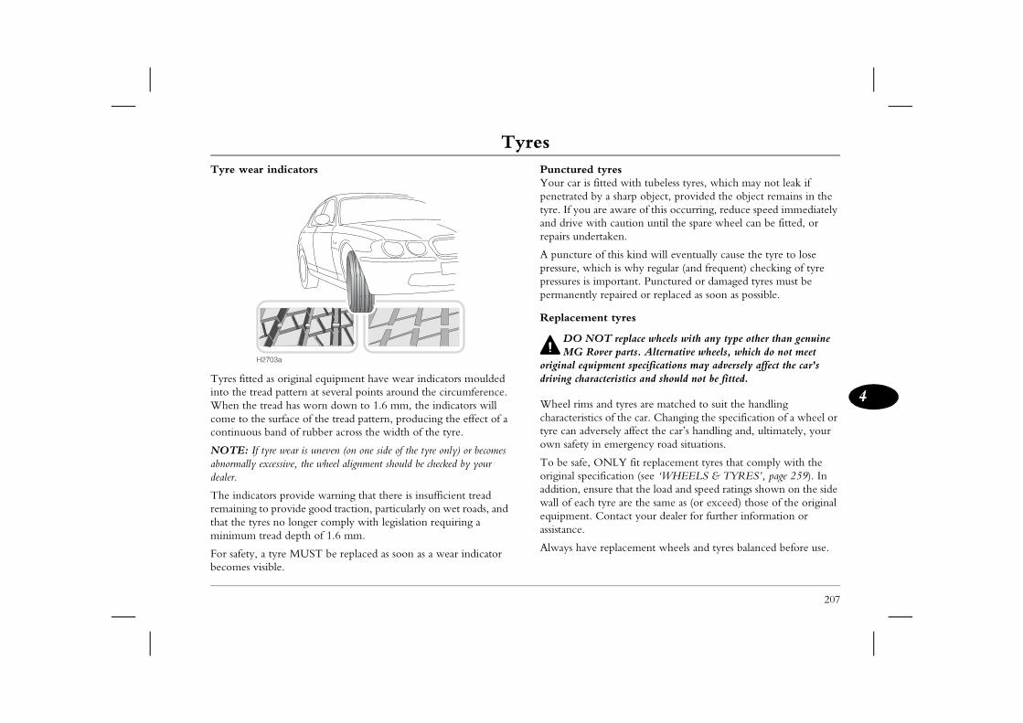
Tyres
207
4
tyresfitted with tubeless tyres, which may not leak if y a sharp object, provided the object remains in the
are aware of this occurring, reduce speed immediately ith caution until the spare wheel can be fitted, or rtaken.
of this kind will eventually cause the tyre to lose ich is why regular (and frequent) checking of tyre
important. Punctured or damaged tyres must be repaired or replaced as soon as possible.
nt tyres
OT replace wheels with any type other than genuine over parts. Alternative wheels, which do not meet ipment specifications may adversely affect the car's acteristics and should not be fitted.
and tyres are matched to suit the handling cs of the car. Changing the specification of a wheel or ersely affect the car’s handling and, ultimately, your n emergency road situations.
ONLY fit replacement tyres that comply with the ification (see ‘WHEELS & TYRES’, page 259). In sure that the load and speed ratings shown on the side tyre are the same as (or exceed) those of the original Contact your dealer for further information or
replacement wheels and tyres balanced before use.
Tyre wear indicators
Tyres fitted as original equipment have wear indicators moulded into the tread pattern at several points around the circumference. When the tread has worn down to 1.6 mm, the indicators will come to the surface of the tread pattern, producing the effect of a continuous band of rubber across the width of the tyre.
NOTE: If tyre wear is uneven (on one side of the tyre only) or becomes abnormally excessive, the wheel alignment should be checked by your dealer.
The indicators provide warning that there is insufficient tread remaining to provide good traction, particularly on wet roads, and that the tyres no longer comply with legislation requiring a minimum tread depth of 1.6 mm.
For safety, a tyre MUST be replaced as soon as a wear indicator becomes visible.
PuncturedYour car is penetrated btyre. If you and drive wrepairs unde
A puncture pressure, whpressures is permanently
Replaceme
DO NMG R
original equdriving char
Wheel rimscharacteristityre can advown safety i
To be safe, original specaddition, enwall of eachequipment.assistance.
Always have
H2703a
TyresSNOW CHAINS
DO NOT fit unapproved snow chains - this could damage
208
brake components.
Unsuitable snow chains could damage the tyres, wheels, suspension, brakes or bodywork of your car. Only fit chains that have been recommended by an MG Rover dealer and approved by MG Rover for use on your car.
In use, always observe the following precautions:• Fit snow chains to the front wheels only.• Always adhere to the snow chain fitting and retensioning
instructions and the speed limitations for varying road conditions.
• DO NOT exceed speeds of 50 km/h.• Avoid tyre damage and excessive chain wear by removing snow
chains when driving on snow free roads.
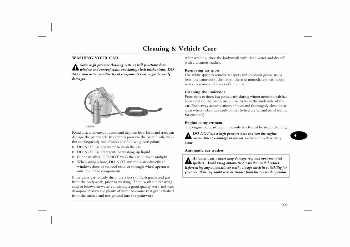
Cleaning & Vehicle Care
209
4
Cleaning & Vehicle Care g, rinse the bodywork with clean water and dry off ois leather.
tar spotspirit to remove tar spots and stubborn grease stains intwork, then wash the area immediately with soapy ove all traces of the spirit.
he undersideo time, but particularly during winter months if salt has n the roads, use a hose to wash the underside of the ay accumulations of mud and thoroughly clean those
debris can easily collect (wheel arches and panel seams, ).
partment compartment must only be cleaned by steam cleaning.
OT use a high pressure hose to clean the engine tment - damage to the car's electronic systems may
car washes
atic car washes may damage roof and boot mounted s. Avoid using automatic car washes with brushes. any automatic car wash, always check its suitability for in any doubt seek assistance from the car wash operator.
WASHING YOUR CAR
Some high pressure cleaning systems will penetrate door, window and sunroof seals, and damage lock mechanisms. DO
NOT aim water jets directly at components that might be easily damaged.
Road dirt, airborne pollutants and deposits from birds and trees can damage the paintwork. In order to preserve the paint finish, wash the car frequently and observe the following care points:• DO NOT use hot water to wash the car.• DO NOT use detergents or washing up liquid.• In hot weather, DO NOT wash the car in direct sunlight.• When using a hose, DO NOT aim the water directly at
window, door or sunroof seals, or through wheel apertures onto the brake components.
If the car is particularly dirty, use a hose to flush grime and grit from the bodywork, prior to washing. Then, wash the car using cold or lukewarm water containing a good quality wash and wax shampoo. Always use plenty of water to ensure that grit is flushed from the surface and not ground into the paintwork.
After washinwith a cham
RemovingUse white sfrom the pawater to rem
Cleaning tFrom time tbeen used ocar. Flush awareas wherefor example
Engine comThe engine
DO Ncompar
occur.
Automatic
Automspoiler
Before usingyour car. If
HB0068
Cleaning & Vehicle CareBody protectionAfter washing, examine the paintwork for damage. Treat paint chips and scratches with an MG Rover paint touch-up pencil. If
Windows and mirrorsRegularly clean all windows, inside and out, using an approved glass cleaner.
ticular, clean the outside of the screen with glass ing the car with wash and wax products, and wiper blades.
the inside with a soft cloth, using a side to side amaging the heating elements. DO NOT scrape asive cleaning compounds - this will damage the
h soapy water. Use a plastic scraper to remove abrasive cleaning compounds or metal scrapers.
210
the damage has revealed bare metal, use a coloured primer first, then apply the correct colour base coat and finish off with a lacquer pencil, if appropriate. Carry out this treatment after washing but before polishing or waxing.
More extensive damage to paint or bodywork must be repaired in accordance with the manufacturer’s recommendations. Failure to do this will invalidate the Anti-Corrosion Warranty. If in doubt, ask your MG Rover dealer for advice.
Polishing the paintworkOccasionally treat the paint surface with an approved polish containing the following properties:• Very mild abrasives that will remove surface contamination
without removing or damaging the paint.• Filling compounds that will fill scratches and reduce their
visibility. • Wax to provide a protective coating between the paint and the
elements.
If possible, avoid applying polish or wax products to window glass and rubber seals.
Wiper bladesWash in warm soapy water. DO NOT use spirit or petrol based cleaners.
Windscreen: In parcleaner after washbefore fitting new
Rear screen: Clean motion to avoid dthe glass or use abrheating elements.
Mirrors: Wash witice. DO NOT use
Cleaning & Vehicle Care
211
4
dule coversdamage to the airbag SRS, the following areas should paringly with a damp cloth and upholstery cleaner
wheel centre pad.ashboard containing the passenger airbag.oof lining and front pillar finishers which enclose the impact protection modules.
OT allow these areas to be flooded with liquid and DO use petrol, detergent, furniture cream or polishes.
belts, then use warm water and a non-detergent soap low the belts to dry naturally; DO NOT retract them ar until they are completely dry.
OT use bleaches, dyes or cleaning solvents on seat belts.
CLEANING THE INTERIORPlastic materialsClean plastic-faced materials with diluted upholstery cleaner, then wipe with a damp cloth.
NOTE: DO NOT polish dashboard components - these should remain non-reflective.
Carpet and fabricsClean with diluted upholstery cleaner - test a concealed area first.
Leather Clean leather trim with warm water and a non-detergent soap. Dry and polish the leather with a dry, clean, lint-free cloth.
NOTE: DO NOT use petrol, detergents, furniture creams or polishes as cleaning agents.
Instrument pack, clock, audio system and navigation displaysClean with a dry cloth only. DO NOT use cleaning fluids or sprays.
Audio system detachable control panelPeriodically clean the electrical contacts on the back of the control panel and the matching contacts on the audio unit with a clean, dry, lint-free cloth. Use methylated spirits if available.
Airbag moTo prevent be cleaned sONLY:• Steering • Area of d• Area of r
side head
DO NNOT
Seat beltsExtend the to clean. Alor use the c
DO N
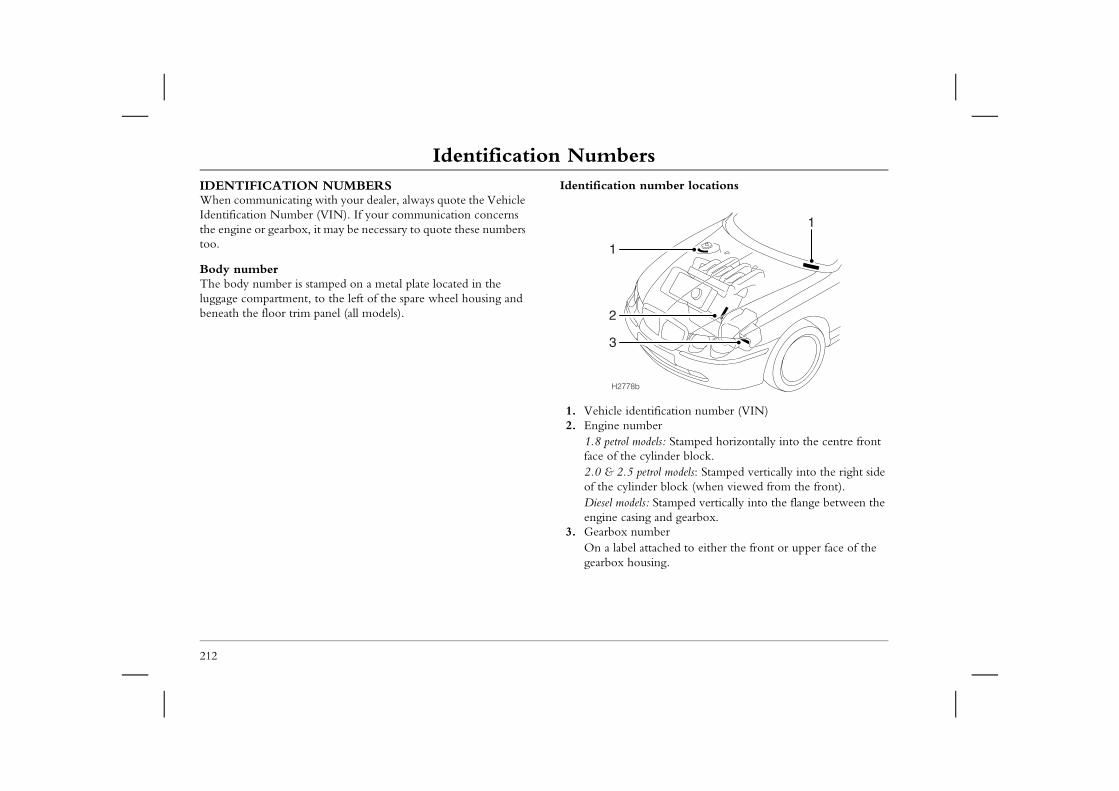
Identification NumbersIdentification NumbersIDENTIFICATION NUMBERSWhen communicating with your dealer, always quote the Vehicle Identification Number (VIN). If your communication concerns
Identification number locations
ification number (VIN)erels: Stamped horizontally into the centre front linder block.rol models: Stamped vertically into the right side r block (when viewed from the front).
Stamped vertically into the flange between the and gearbox.ber
tached to either the front or upper face of the ing.
1
212
the engine or gearbox, it may be necessary to quote these numbers too.
Body numberThe body number is stamped on a metal plate located in the luggage compartment, to the left of the spare wheel housing and beneath the floor trim panel (all models).
1. Vehicle ident2. Engine numb
1.8 petrol modface of the cy2.0 & 2.5 petof the cylindeDiesel models:engine casing
3. Gearbox numOn a label atgearbox hous
H2778b
2
1
3
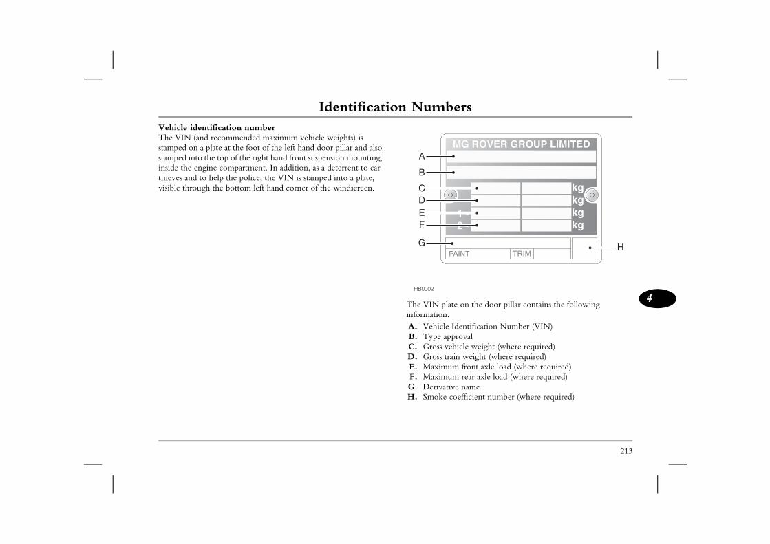
Identification Numbers
213
4late on the door pillar contains the following : Identification Number (VIN) pprovalehicle weight (where required)rain weight (where required)um front axle load (where required)um rear axle load (where required)tive name coefficient number (where required)
H
Vehicle identification numberThe VIN (and recommended maximum vehicle weights) is stamped on a plate at the foot of the left hand door pillar and also stamped into the top of the right hand front suspension mounting, inside the engine compartment. In addition, as a deterrent to car thieves and to help the police, the VIN is stamped into a plate, visible through the bottom left hand corner of the windscreen.
The VIN pinformationA. VehicleB. Type aC. Gross vD. Gross tE. MaximF. MaximG. DerivaH. Smoke
HB0002
A
B
CDEF
G
Parts & AccessoriesParts & AccessoriesPARTS & ACCESSORIES
The fitting of parts and accessories that have not been approved
It is extremely hazardous to fit parts or accessories where installation requires the dismantling of, or addition to, either
the electrical or fuel systems.
ription of all accessories is available from your .
d it is illegal to fit parts which have not been made ufacturer's specification.
sure that any parts or accessories fitted to the car road, will also conform to the legal requirements ntry.
214
by MG Rover, or the carrying out of non-approved alterations or conversions, may be dangerous and could affect the safety of the car and occupants, and also invalidate the terms and conditions of the car's warranty.
Your car has been carefully designed and manufactured to exude luxury, class and style.
To ensure your future driving pleasure and safety, we strongly recommend that only MG Rover approved parts are fitted to your car. Genuine MG Rover parts and accessories are the only components approved by MG Rover to meet rigorous original equipment standards for fitment and performance.
To enhance your motoring pleasure, a comprehensive and versatile range of quality accessories is available. This wide range of genuine MG Rover products is an integral part of the car's design and development programme and will help to guarantee continued reliability, safety and performance.
An airbag SRS is fitted to your car, ALWAYS consult an MG Rover dealer before fitting any accessory.
Genuine MG Rover parts are the ONLY parts built to original equipment specifications AND approved by MG Rover designers; this means that every single part and accessory has been thoroughly tested by the same engineering team that designed and built the car. As a result, all genuine MG Rover parts and accessories are guaranteed for twelve months, regardless of distance travelled.
A full list and descMG Rover dealer
Travelling abroaIn some countries,to the vehicle man
Owners should enwhile travelling abof their home cou
5
Emergency Information
216 Emergency Starting219 Vehicle Recovery222 Puncture Repair & Wheel Changing233 Fuse Replacement237 Bulb Replacement
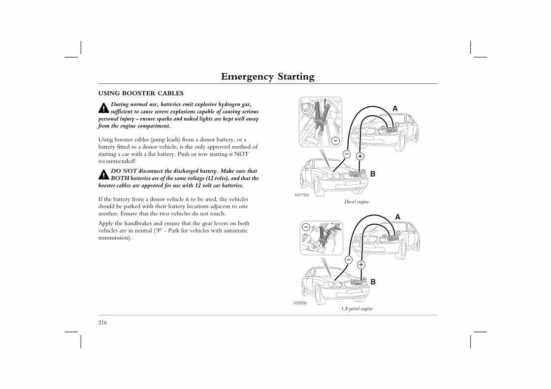
Emergency StartingEmergency InformationEmergency StartingUSING BOOSTER CABLES
During normal use, batteries emit explosive hydrogen gas,
Diesel engine
1.8 petrol engine
B
A
B
A
216
sufficient to cause severe explosions capable of causing serious personal injury - ensure sparks and naked lights are kept well away from the engine compartment.
Using booster cables (jump leads) from a donor battery, or a battery fitted to a donor vehicle, is the only approved method of starting a car with a flat battery. Push or tow starting is NOT recommended!
DO NOT disconnect the discharged battery. Make sure that BOTH batteries are of the same voltage (12 volts), and that the
booster cables are approved for use with 12 volt car batteries.
If the battery from a donor vehicle is to be used, the vehicles should be parked with their battery locations adjacent to one another. Ensure that the two vehicles do not touch.
Apply the handbrakes and ensure that the gear levers on both vehicles are in neutral (‘P’ - Park for vehicles with automatic transmission).
H2776b
H2859b
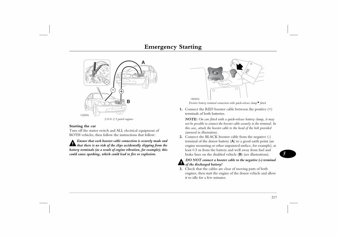
Emergency Starting
217
5
ve battery terminal connection with quick-release clamp* fitted
ct the RED booster cable between the positive (+) als of both batteries.
: On cars fitted with a quick-release battery clamp, it may ossible to connect the booster cable securely to the terminal. In , attach the booster cable to the head of the bolt provided in illustration).ct the BLACK booster cable from the negative (-) al of the donor battery (A) to a good earth point (an mounting or other unpainted surface, for example), at 5 m from the battery and well away from fuel and ines on the disabled vehicle (B) (see illustrations).
OT connect a booster cable to the negative (-) terminal ischarged battery!that the cables are clear of moving parts of both s, then start the engine of the donor vehicle and allow le for a few minutes.
655
2.0 & 2.5 petrol engines
Starting the carTurn off the starter switch and ALL electrical equipment of BOTH vehicles, then follow the instructions that follow:
Ensure that each booster cable connection is securely made and that there is no risk of the clips accidentally slipping from the
battery terminals (as a result of engine vibration, for example); this could cause sparking, which could lead to fire or explosion.
Positi
1. Connetermin
NOTEnot be pthis case(arrowed
2. Conneterminengineleast 0.brake l
DO Nof the d
3. Check engineit to id
H2860b
B
A
HB0
Emergency Starting4. Now start the engine of the vehicle with the discharged
battery (DO NOT crank the engine for more than 15 seconds).
218
5. Once both engines are running normally, allow them to idle for two minutes before switching off the engine of the donor vehicle and disconnecting the booster cables. DO NOT switch on any electrical circuits on the previously disabled vehicle until AFTER the booster cables have been removed.
6. Disconnecting the booster cables must be an exact reversal of the procedure used to connect them, i.e. disconnect the BLACK cable from the earth point on the disabled vehicle FIRST.
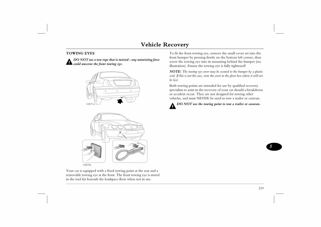
Vehicle Recovery
219
5
Vehicle Recovery ont towing eye, remove the small cover set into the er by pressing firmly on the bottom left corner, then wing eye into its mounting behind the bumper (see Ensure the towing eye is fully tightened!
e towing eye cover may be secured to the bumper by a plastic not the case, store the cover in the glove box where it will not
g points are intended for use by qualified recovery assist in the recovery of your car should a breakdown occur. They are not designed for towing other d must NEVER be used to tow a trailer or caravan.
OT use the towing point to tow a trailer or caravan.
TOWING EYES
DO NOT use a tow rope that is twisted - any untwisting force could unscrew the front towing eye.
Your car is equipped with a fixed towing point at the rear and a removable towing eye at the front. The front towing eye is stored in the tool kit beneath the loadspace floor when not in use.
To fit the frfront bumpscrew the toillustration).
NOTE: Thcord. If this isbe lost.
Both towinspecialists toor accident vehicles, an
DO NH2671a
H2670b
Vehicle RecoveryTOWING FOR RECOVERYIf your car is to be towed, most qualified recovery specialists will use wheel lift equipment to suspend the front wheels, while the
Automatic transmission carsIdeally, cars fitted with an automatic gearbox should only be moved by trailer/transporter, or on suspended tow (with the front
re unavailable and it is ESSENTIAL for the car l four wheels, adhere strictly to the following: w the car to be towed further than 50 km.wing speed to a maximum of 50 km/h.
220
rear wheels remain on the ground. However, if it is necessary for the car to be towed with all four wheels on the ground, abide by the following procedure.
Before being towed:
DO NOT remove the starter key or turn the starter switch off while the car is being towed on four wheels - this will prevent
the steering wheel from being turned.
1. Turn the starter key to the first position to unlock the steering and then to the second position to enable the brake lights, wipers and direction indicators to be operated if necessary.If, due to an accident or electrical fault, it is considered unsafe to turn the starter switch to the first position, disconnect the battery before turning the switch.
2. Place the gear lever in neutral (‘N’ for cars with automatic transmission).
3. Release the handbrake.
While being towed observe the following:• Without the engine running, greater effort will be required to
operate the brake pedal and turn the steering wheel. Longer stopping distances will also be experienced.
• While towing for recovery, the towing vehicle should never exceed 50 km/h.
wheels raised).
If these facilities ato be towed on al• DO NOT allo• Restrict the to
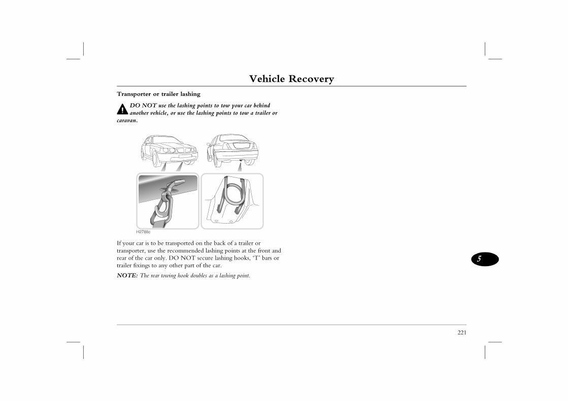
Vehicle Recovery
221
5
Transporter or trailer lashing
DO NOT use the lashing points to tow your car behind another vehicle, or use the lashing points to tow a trailer or
caravan.
If your car is to be transported on the back of a trailer or transporter, use the recommended lashing points at the front and rear of the car only. DO NOT secure lashing hooks, ‘T’ bars or trailer fixings to any other part of the car.
NOTE: The rear towing hook doubles as a lashing point.
H2788c

Puncture Repair & Wheel ChangingPuncture Repair & Wheel ChangingINSTANT TYRE REPAIR (ITR) COMPONENTS*
1. Tyre sealant canister.2. Safety goggles.3. Wheel bolt cover removal tool*.4. Locking wheel bolt removal tool*.5. Screwdriver*.
NOTE: ITR is standard equipment for most cars and is designed to provide a temporary repair solution for most tyre tread punctures.
For information on how to use ITR, please refer to ‘INSTANT TYRE REPAIR (ITR)*’, page 225.
222
ALWAYS read and obey all instructions and warnings printed on the tyre sealant canister.
HB0639
1
2
5
3
4
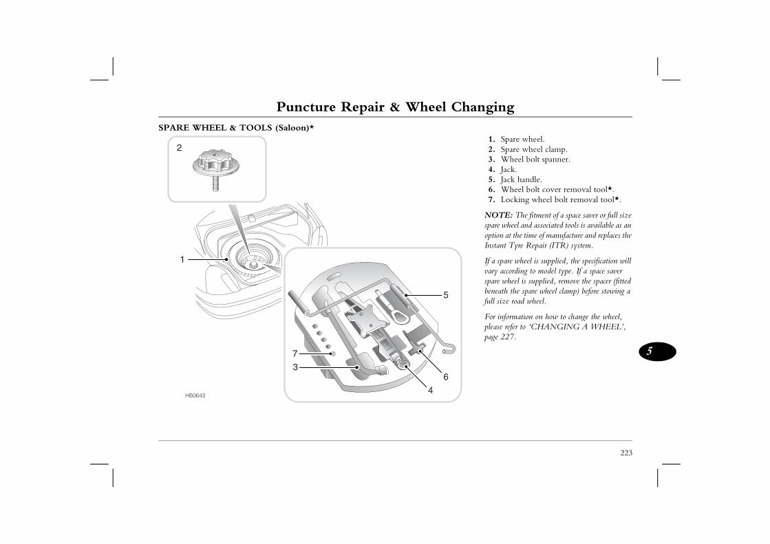
223
Puncture Repair & Wheel Changing
5
1. Spare wheel.2. Spare wheel clamp.3. Wheel bolt spanner.4. Jack.5. Jack handle.6. Wheel bolt cover removal tool*.7. Locking wheel bolt removal tool*.
NOTE: The fitment of a space saver or full size spare wheel and associated tools is available as an option at the time of manufacture and replaces the Instant Tyre Repair (ITR) system.
If a spare wheel is supplied, the specification will vary according to model type. If a space saver spare wheel is supplied, remove the spacer (fitted beneath the spare wheel clamp) before stowing a full size road wheel.
For information on how to change the wheel, please refer to ‘CHANGING A WHEEL’, page 227.
HB0643
7
6
5
4
3
SPARE WHEEL & TOOLS (Saloon)*
1
2
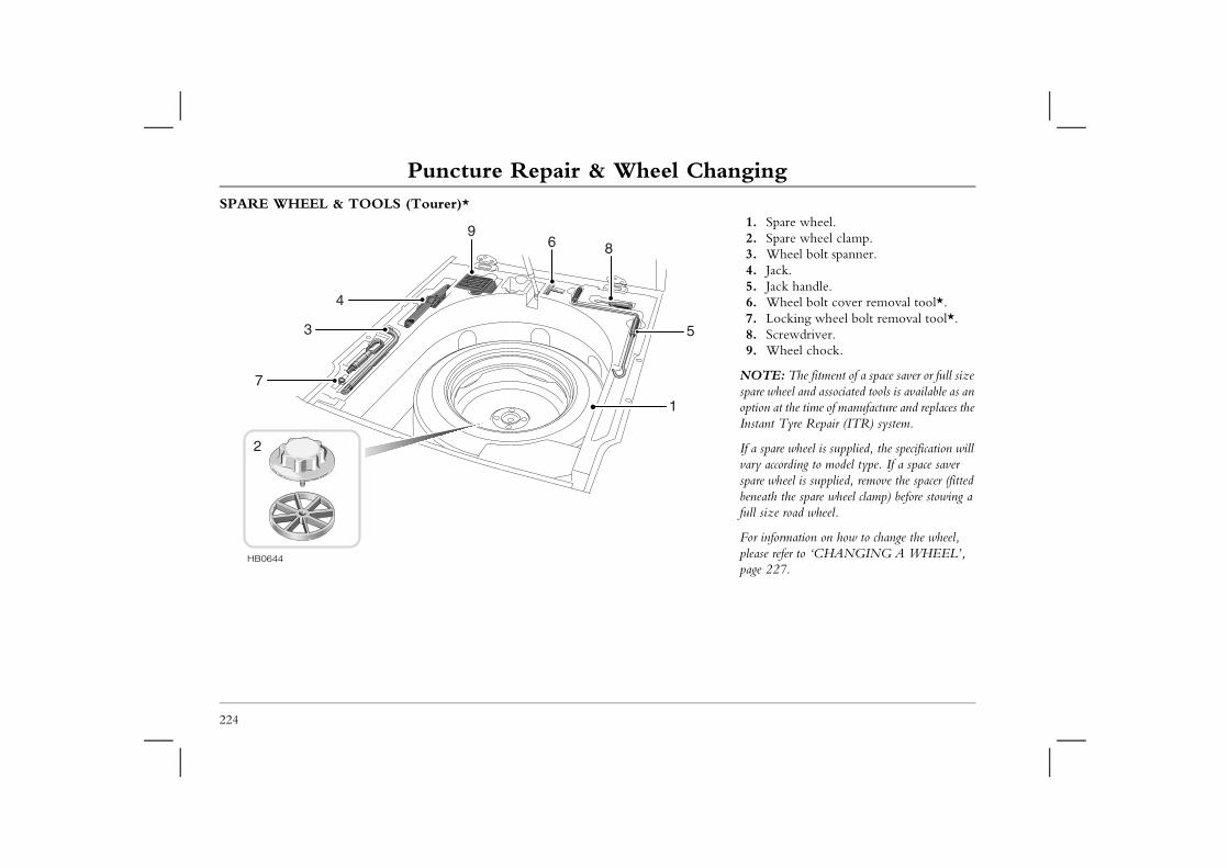
Puncture Repair & Wheel ChangingSPARE WHEEL & TOOLS (Tourer)*
91. Spare wheel.2. Spare wheel clamp.3. Wheel bolt spanner.4. Jack.5. Jack handle.6. Wheel bolt cover removal tool*.7. Locking wheel bolt removal tool*.8. Screwdriver.9. Wheel chock.
NOTE: The fitment of a space saver or full size spare wheel and associated tools is available as an option at the time of manufacture and replaces the Instant Tyre Repair (ITR) system.
If a spare wheel is supplied, the specification will vary according to model type. If a space saver spare wheel is supplied, remove the spacer (fitted beneath the spare wheel clamp) before stowing a full size road wheel.
For information on how to change the wheel, please refer to ‘CHANGING A WHEEL’, page 227.
224
HB0644
2
7
4
6 8
5
1
3
Puncture Repair & Wheel Changing
225
5
he tyre sealant canister out of the reach of children. Store ister in its correct location beneath the loadspace floor; s in other locations may exceed safe storage conditions.
OT puncture or incinerate the canister, or expose to lame or direct sunlight - this may cause the canister to
no circumstances should speeds of 45 km/h be exceeded, riving with a tyre repaired using ITR, until the tyre is s correct pressure. Once the tyre is correctly inflated, the T be driven at speeds exceeding 80 km/h.
the deflated tyre for cause of puncture. If possible, foreign bodies (e.g: screws and nails) from the tread.
: The system can be used to repair small punctures in the ly. In the event of side wall or severe tread damage, seek ce from the breakdown services.e the tyre sealant canister and the safety goggles from
r loadspace and put on the safety goggles.
: If the ambient temperature is below 0° C, warm the canister e car, using the car heating system.e the valve cap from the punctured tyre.usly shake the canister (for approximately 30 seconds), rew the filler tube clockwise onto the tyre valve.
INSTANT TYRE REPAIR (ITR)*ITR provides a temporary solution to enable you to reach a dealer or tyre specialist, where the tyre must be repaired or replaced. Have the tyre repaired or replaced as soon as possible.
Always choose a safe place to stop, away from the main thoroughfare. Always ask your passengers to get out of the car and wait in a safe area away from other traffic.
NOTE: Switch on the hazard warning lights to alert other road users.
SAFETY PRECAUTIONS
Read the directions and warnings on the sealant canister beforehand and wear the safety goggles supplied when using
the sealant.
The tyre sealant contains fluorocarbons and solvents which are harmful if swallowed or inhaled and are irritating to the eyes.
• If swallowed, DO NOT induce vomiting - seek medical assistance immediately.
• If inhaled, breathe fresh air. If breathing is adversely affected, seek immediate medical assistance.
• If in contact with the eyes, immediately flush the eyes with water for 15 minutes. If irritation persists, seek medical assistance.
• DO NOT breathe gas/fumes/vapour/spray from the canister. Inhalation of canister vapours may cause drowsiness and dizziness.
Keep tthe can
temperature
DO Nheat, f
rupture.
Under when d
inflated to itcar must NO
Using ITR1. Inspect
remove
NOTEtread onassistan
2. Removthe rea
NOTEinside th
3. Remov4. Vigoro
then sc
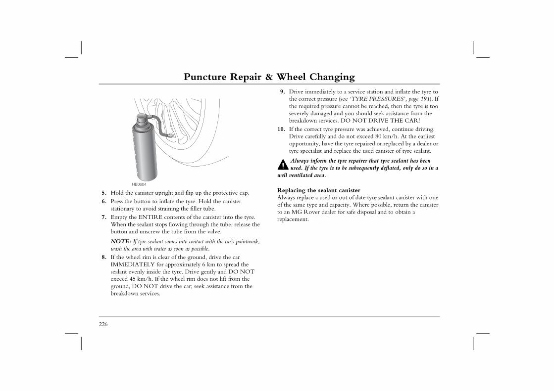
Puncture Repair & Wheel Changing9. Drive immediately to a service station and inflate the tyre to
the correct pressure (see ‘TYRE PRESSURES’, page 191). If the required pressure cannot be reached, then the tyre is too
aged and you should seek assistance from the rvices. DO NOT DRIVE THE CAR!
tyre pressure was achieved, continue driving. ly and do not exceed 80 km/h. At the earliest have the tyre repaired or replaced by a dealer or and replace the used canister of tyre sealant.
m the tyre repairer that tyre sealant has been yre is to be subsequently deflated, only do so in a a.
alant canistersed or out of date tyre sealant canister with one nd capacity. Where possible, return the canister dealer for safe disposal and to obtain a
226
5. Hold the canister upright and flip up the protective cap.6. Press the button to inflate the tyre. Hold the canister
stationary to avoid straining the filler tube. 7. Empty the ENTIRE contents of the canister into the tyre.
When the sealant stops flowing through the tube, release the button and unscrew the tube from the valve.
NOTE: If tyre sealant comes into contact with the car's paintwork, wash the area with water as soon as possible.
8. If the wheel rim is clear of the ground, drive the car IMMEDIATELY for approximately 6 km to spread the sealant evenly inside the tyre. Drive gently and DO NOT exceed 45 km/h. If the wheel rim does not lift from the ground, DO NOT drive the car; seek assistance from the breakdown services.
severely dambreakdown se
10. If the correctDrive carefulopportunity, tyre specialist
Always inforused. If the t
well ventilated are
Replacing the seAlways replace a uof the same type ato an MG Rover replacement.
HB0604
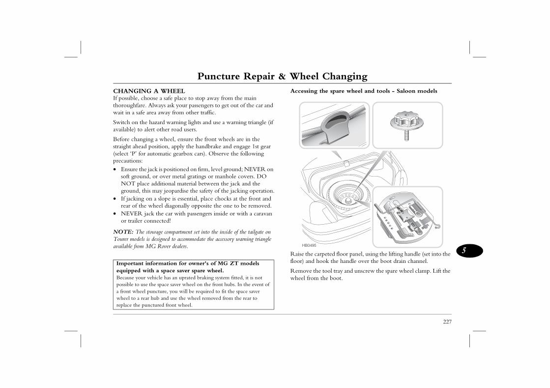
Puncture Repair & Wheel Changing
227
5
the spare wheel and tools - Saloon models
rpeted floor panel, using the lifting handle (set into the ook the handle over the boot drain channel.
tool tray and unscrew the spare wheel clamp. Lift the the boot.
CHANGING A WHEELIf possible, choose a safe place to stop away from the main thoroughfare. Always ask your passengers to get out of the car and wait in a safe area away from other traffic.
Switch on the hazard warning lights and use a warning triangle (if available) to alert other road users.
Before changing a wheel, ensure the front wheels are in the straight ahead position, apply the handbrake and engage 1st gear (select ‘P’ for automatic gearbox cars). Observe the following precautions: • Ensure the jack is positioned on firm, level ground; NEVER on
soft ground, or over metal gratings or manhole covers. DO NOT place additional material between the jack and the ground, this may jeopardise the safety of the jacking operation.
• If jacking on a slope is essential, place chocks at the front and rear of the wheel diagonally opposite the one to be removed.
• NEVER jack the car with passengers inside or with a caravan or trailer connected!
NOTE: The stowage compartment set into the inside of the tailgate on Tourer models is designed to accommodate the accessory warning triangle available from MG Rover dealers.
Accessing
Raise the cafloor) and h
Remove thewheel from
Important information for owner's of MG ZT models equipped with a space saver spare wheel.Because your vehicle has an uprated braking system fitted, it is not possible to use the space saver wheel on the front hubs. In the event of a front wheel puncture, you will be required to fit the space saver wheel to a rear hub and use the wheel removed from the rear to replace the punctured front wheel.
HB0495
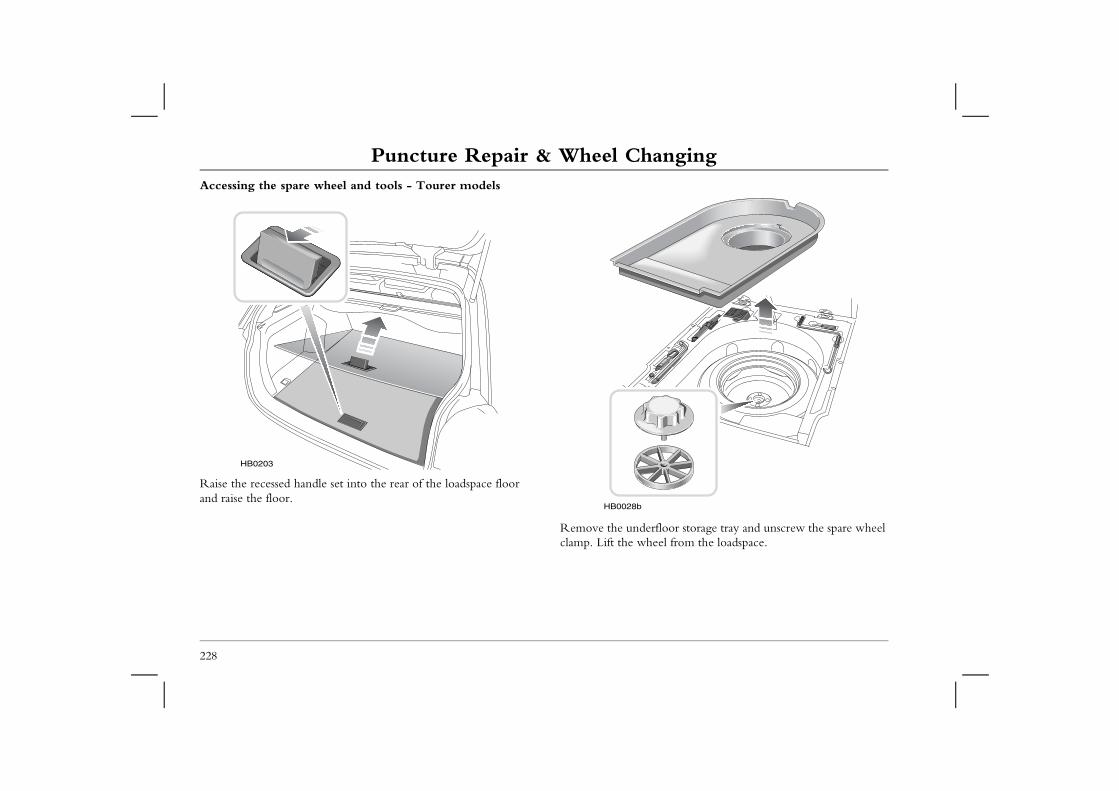
Puncture Repair & Wheel ChangingAccessing the spare wheel and tools - Tourer models
rfloor storage tray and unscrew the spare wheel eel from the loadspace.
228
Raise the recessed handle set into the rear of the loadspace floor and raise the floor.
Remove the undeclamp. Lift the wh
HB0203
HB0028b
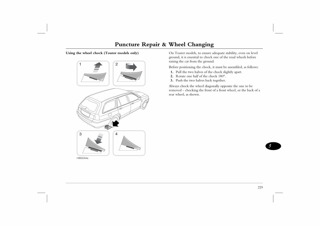
Puncture Repair & Wheel Changing
229
5
models, to ensure adequate stability, even on level essential to chock one of the road wheels before ar from the ground.
ioning the chock, it must be assembled, as follows: e two halves of the chock slightly apart. one half of the chock 180°.e two halves back together.
ck the wheel diagonally opposite the one to be hocking the front of a front wheel, or the back of a as shown.
Using the wheel chock (Tourer models only) On Tourer ground, it israising the c
Before posit1. Pull th2. Rotate3. Push th
Always choremoved - crear wheel,
HB0044a
1 2
3 4
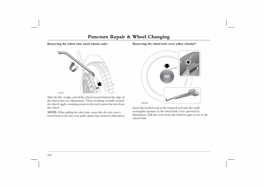
Puncture Repair & Wheel ChangingRemoving the wheel trim (steel wheels only) Removing the wheel bolt cover (alloy wheels)*
end of the removal tool into the small re in the wheel bolt cover (arrowed in he cover from the wheel to gain access to the
230
Slide the flat, wedge, end of the wheel wrench behind the edge of the wheel trim (see illustration). Then, working carefully around the wheel, apply a twisting action to the tool to prise the trim from the wheel.
NOTE: When refitting the wheel trim, ensure that the valve stem is located between the valve stem guides (plastic lugs arrowed in illustration).
Insert the hookedrectangular apertuillustration). Pull twheel bolts.
H2785
HB0586
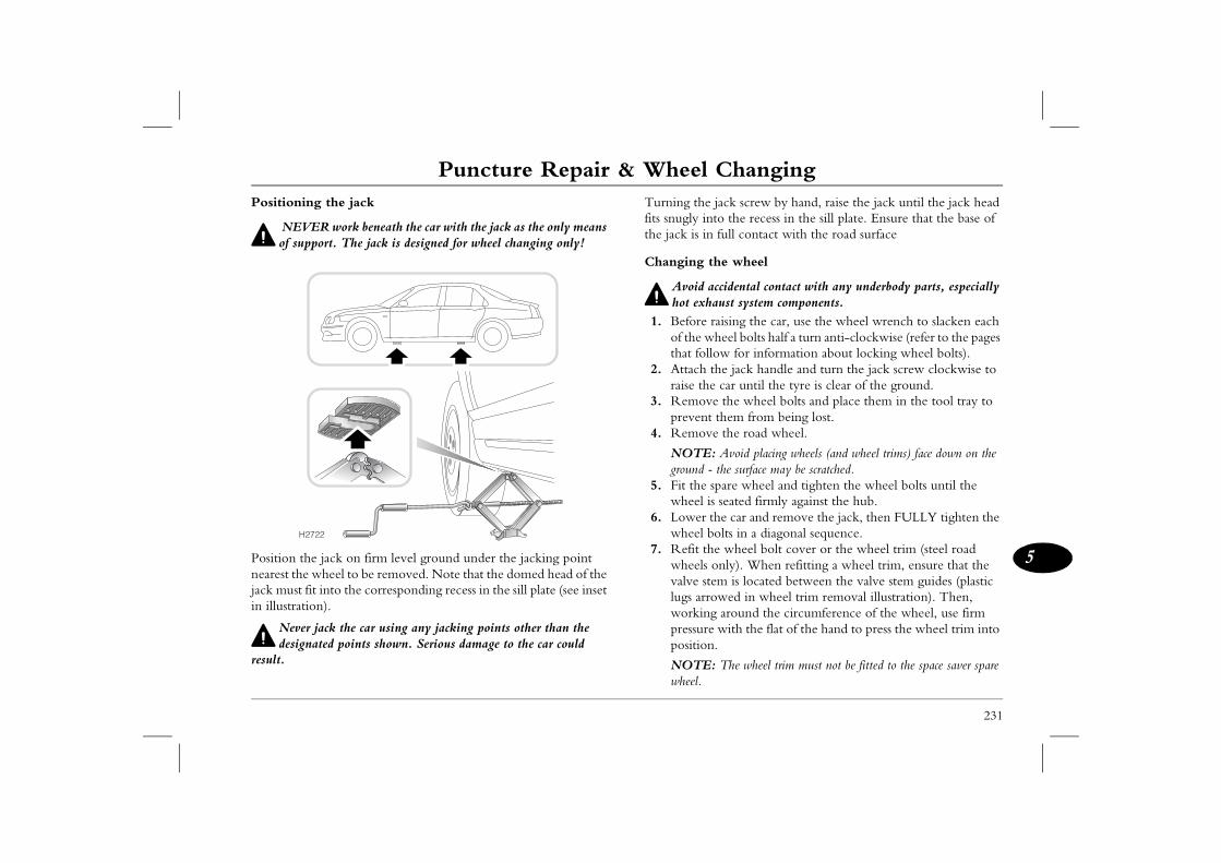
Puncture Repair & Wheel Changing
231
5
jack screw by hand, raise the jack until the jack head to the recess in the sill plate. Ensure that the base of full contact with the road surface
the wheel
accidental contact with any underbody parts, especially aust system components.
raising the car, use the wheel wrench to slacken each heel bolts half a turn anti-clockwise (refer to the pages
low for information about locking wheel bolts).the jack handle and turn the jack screw clockwise to e car until the tyre is clear of the ground. e the wheel bolts and place them in the tool tray to
t them from being lost.e the road wheel.
: Avoid placing wheels (and wheel trims) face down on the - the surface may be scratched.spare wheel and tighten the wheel bolts until the is seated firmly against the hub. the car and remove the jack, then FULLY tighten the bolts in a diagonal sequence.he wheel bolt cover or the wheel trim (steel road only). When refitting a wheel trim, ensure that the em is located between the valve stem guides (plastic owed in wheel trim removal illustration). Then, g around the circumference of the wheel, use firm e with the flat of the hand to press the wheel trim into n.
: The wheel trim must not be fitted to the space saver spare
Positioning the jack
NEVER work beneath the car with the jack as the only means of support. The jack is designed for wheel changing only!
Position the jack on firm level ground under the jacking point nearest the wheel to be removed. Note that the domed head of the jack must fit into the corresponding recess in the sill plate (see inset in illustration).
Never jack the car using any jacking points other than the designated points shown. Serious damage to the car could
result.
Turning thefits snugly inthe jack is in
Changing
Avoid hot exh
1. Beforeof the wthat fol
2. Attach raise th
3. Removpreven
4. Remov
NOTEground
5. Fit the wheel
6. Lower wheel
7. Refit twheelsvalve stlugs arrworkinpressurpositio
NOTEwheel.
H2722
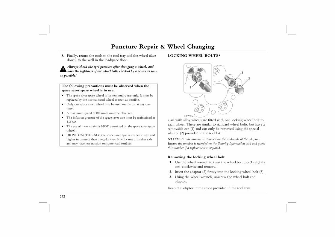
Puncture Repair & Wheel Changing8. Finally, return the tools to the tool tray and the wheel (face
down) to the well in the loadspace floor.LOCKING WHEEL BOLTS*
heels are fitted with one locking wheel bolt to are similar to standard wheel bolts, but have a and can only be removed using the special ed in the tool kit.
mber is stamped on the underside of the adaptor. s recorded on the Security Information card and quote acement is required.
ocking wheel boltl wrench to twist the wheel bolt cap (1) slightly e and remove.ptor (2) firmly into the locking wheel bolt (3).eel wrench, unscrew the wheel bolt and
in the space provided in the tool tray.
2
3
232
Always check the tyre pressure after changing a wheel, and have the tightness of the wheel bolts checked by a dealer as soon
as possible!
Cars with alloy weach wheel. Theseremovable cap (1)adaptor (2) provid
NOTE: A code nuEnsure the number ithis number if a repl
Removing the l1. Use the whee
anti-clockwis2. Insert the ada3. Using the wh
adaptor.
Keep the adaptor
The following precautions must be observed when the space saver spare wheel is in use:
• The space saver spare wheel is for temporary use only. It must be replaced by the normal sized wheel as soon as possible.
• Only one space saver wheel is to be used on the car at any one time.
• A maximum speed of 80 km/h must be observed.• The inflation pressure of the space saver tyre must be maintained at
4.2 bar.• The use of snow chains is NOT permitted on the space saver spare
wheel.• DRIVE CAUTIOUSLY; the space saver tyre is smaller in size and
higher in pressure than a regular tyre. It will cause a harsher ride and may have less traction on some road surfaces.
H2757a
1
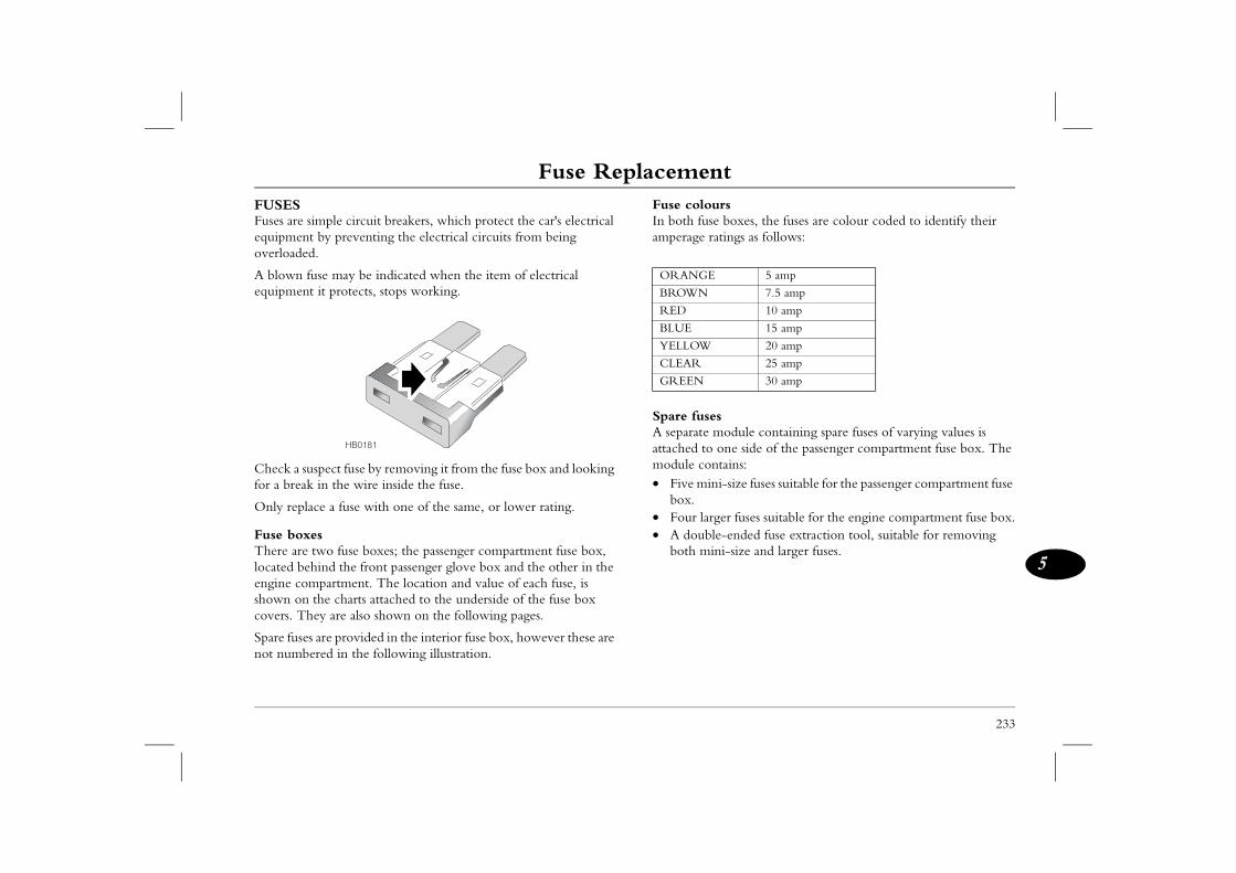
Fuse Replacement
233
5
Fuse Replacement rs boxes, the fuses are colour coded to identify their tings as follows:
sodule containing spare fuses of varying values is
one side of the passenger compartment fuse box. The tains:i-size fuses suitable for the passenger compartment fuse
er fuses suitable for the engine compartment fuse box.-ended fuse extraction tool, suitable for removing i-size and larger fuses.
5 amp
7.5 amp
10 amp
15 amp
20 amp
25 amp
30 amp
FUSESFuses are simple circuit breakers, which protect the car's electrical equipment by preventing the electrical circuits from being overloaded.
A blown fuse may be indicated when the item of electrical equipment it protects, stops working.
Check a suspect fuse by removing it from the fuse box and looking for a break in the wire inside the fuse.
Only replace a fuse with one of the same, or lower rating.
Fuse boxesThere are two fuse boxes; the passenger compartment fuse box, located behind the front passenger glove box and the other in the engine compartment. The location and value of each fuse, is shown on the charts attached to the underside of the fuse box covers. They are also shown on the following pages.
Spare fuses are provided in the interior fuse box, however these are not numbered in the following illustration.
Fuse colouIn both fuseamperage ra
Spare fuseA separate mattached to module con• Five min
box.• Four larg• A double
both min
HB0181
ORANGE
BROWN
RED
BLUE
YELLOW
CLEAR
GREEN
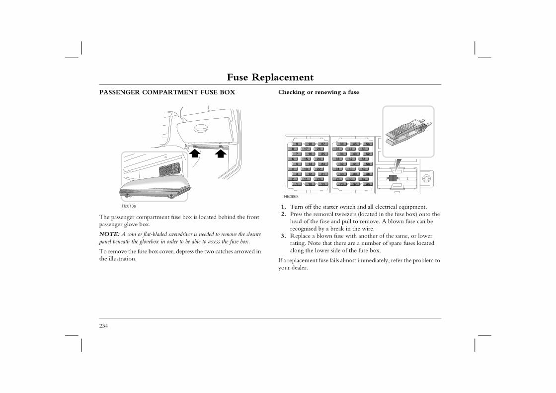
Fuse ReplacementPASSENGER COMPARTMENT FUSE BOX Checking or renewing a fuse
starter switch and all electrical equipment.oval tweezers (located in the fuse box) onto the se and pull to remove. A blown fuse can be a break in the wire.wn fuse with another of the same, or lower
that there are a number of spare fuses located er side of the fuse box.
se fails almost immediately, refer the problem to
9
1
3
5
7
28
29
30
31
32
33
34
3536
37
38
39
40
41
42
43
4445
46
47
48
49
50
51
52
5354
234
The passenger compartment fuse box is located behind the front passenger glove box.
NOTE: A coin or flat-bladed screwdriver is needed to remove the closure panel beneath the glovebox in order to be able to access the fuse box.
To remove the fuse box cover, depress the two catches arrowed in the illustration.
1. Turn off the 2. Press the rem
head of the furecognised by
3. Replace a blorating. Note along the low
If a replacement fuyour dealer.
H2813a
HB0668
1
2
3
4
5
6
7
89
10
11
12
13
14
15
16
1718
1
20
2
22
2
24
2
262
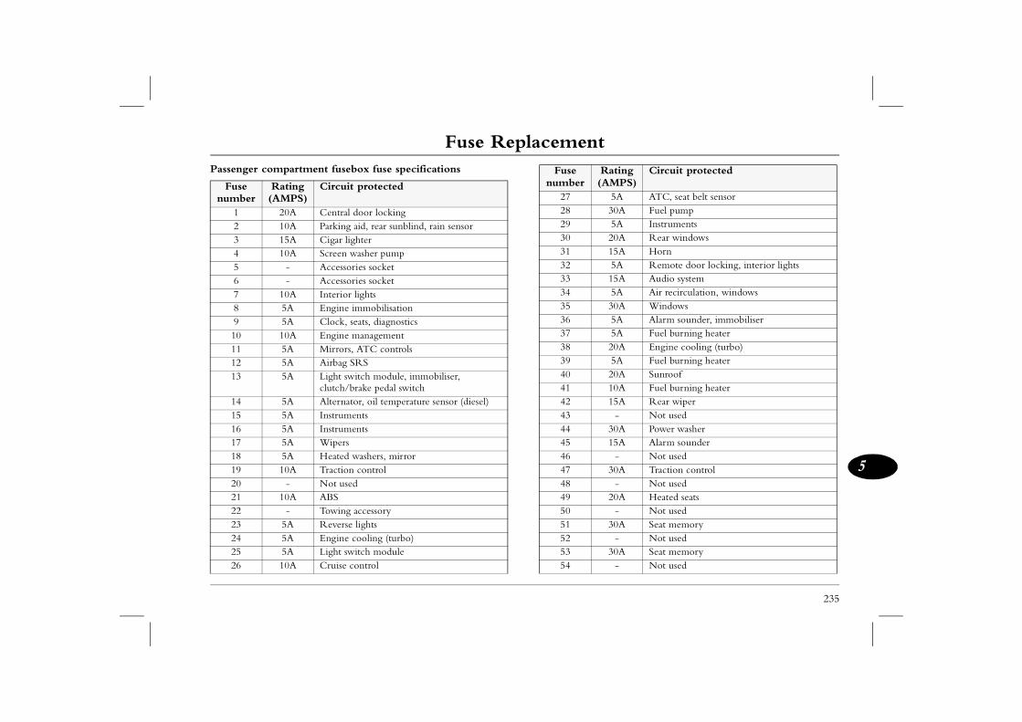
Fuse Replacement
235
5
Passenger compartment fusebox fuse specifications
5A ATC, seat belt sensor30A Fuel pump5A Instruments20A Rear windows15A Horn5A Remote door locking, interior lights15A Audio system5A Air recirculation, windows30A Windows5A Alarm sounder, immobiliser5A Fuel burning heater20A Engine cooling (turbo)5A Fuel burning heater20A Sunroof 10A Fuel burning heater15A Rear wiper
- Not used30A Power washer15A Alarm sounder
- Not used30A Traction control
- Not used20A Heated seats
- Not used30A Seat memory
- Not used30A Seat memory
- Not used
Rating (AMPS)
Circuit protected
Fuse number
Rating (AMPS)
Circuit protected
1 20A Central door locking2 10A Parking aid, rear sunblind, rain sensor3 15A Cigar lighter4 10A Screen washer pump5 - Accessories socket6 - Accessories socket7 10A Interior lights8 5A Engine immobilisation9 5A Clock, seats, diagnostics10 10A Engine management11 5A Mirrors, ATC controls12 5A Airbag SRS 13 5A Light switch module, immobiliser,
clutch/brake pedal switch14 5A Alternator, oil temperature sensor (diesel)15 5A Instruments16 5A Instruments17 5A Wipers18 5A Heated washers, mirror19 10A Traction control20 - Not used21 10A ABS22 - Towing accessory23 5A Reverse lights24 5A Engine cooling (turbo)25 5A Light switch module26 10A Cruise control
27282930313233343536373839404142434445464748495051525354
Fuse number
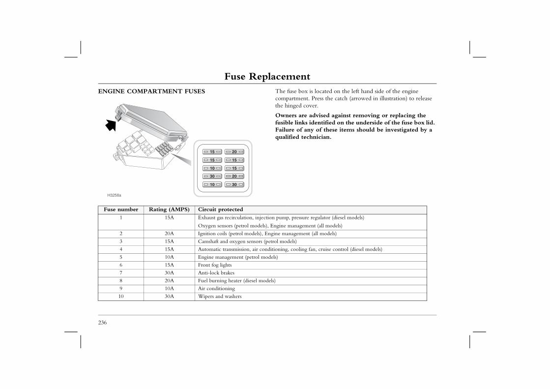
Fuse ReplacementENGINE COMPARTMENT FUSES The fuse box is located on the left hand side of the engine
compartment. Press the catch (arrowed in illustration) to release the hinged cover.
ised against removing or replacing the tified on the underside of the fuse box lid. f these items should be investigated by a ian.
lator (diesel models)
all models)
models)
cruise control (diesel models)
236
Owners are advfusible links idenFailure of any oqualified technic
15
15
10
30
10
20
15
15
30
H3258a
20
Fuse number Rating (AMPS) Circuit protected1 15A Exhaust gas recirculation, injection pump, pressure regu
Oxygen sensors (petrol models), Engine management (
2 20A Ignition coils (petrol models), Engine management (all
3 15A Camshaft and oxygen sensors (petrol models)
4 15A Automatic transmission, air conditioning, cooling fan,
5 10A Engine management (petrol models)
6 15A Front fog lights
7 30A Anti-lock brakes
8 20A Fuel burning heater (diesel models)
9 10A Air conditioning
10 30A Wipers and washers
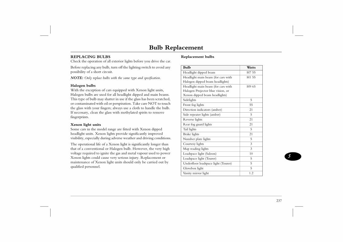
Bulb Replacement
237
5
Bulb Replacement nt bulbs
Wattsipped beam H7 55
ain beam (for cars with ped beam headlights)
H1 55
ain beam (for cars with ojector blue vision, or ed beam headlights)
H9 65
5
hts 55
dicators (amber) 21
r lights (amber) 5
ts 21
ard lights 21
5
21
te lights 5
hts 3
g lights 3
ight (Saloon) 10
ight (Tourer) 5
loadspace light (Tourer) 5
ght 5
or light 1.2
REPLACING BULBSCheck the operation of all exterior lights before you drive the car.
Before replacing any bulb, turn off the lighting switch to avoid any possibility of a short circuit.
NOTE: Only replace bulbs with the same type and specification.
Halogen bulbsWith the exception of cars equipped with Xenon light units, Halogen bulbs are used for all headlight dipped and main beams. This type of bulb may shatter in use if the glass has been scratched, or contaminated with oil or perspiration. Take care NOT to touch the glass with your fingers; always use a cloth to handle the bulb. If necessary, clean the glass with methylated spirits to remove fingerprints.
Xenon light unitsSome cars in the model range are fitted with Xenon dipped headlight units. Xenon lights provide significantly improved visibility, especially during adverse weather and driving conditions.
The operational life of a Xenon light is significantly longer than that of a conventional or Halogen bulb. However, the very high voltage required to ignite the gas and metal vapour used to power Xenon lights could cause very serious injury. Replacement or maintenance of Xenon light units should only be carried out by qualified personnel.
Replaceme
BulbHeadlight d
Headlight mHalogen dip
Headlight mHalogen PrXenon dipp
Sidelights
Front fog lig
Direction in
Side repeate
Reverse ligh
Rear fog gu
Tail lights
Brake lights
Number pla
Courtesy lig
Map readin
Loadspace l
Loadspace l
Underfloor
Glovebox li
Vanity mirr
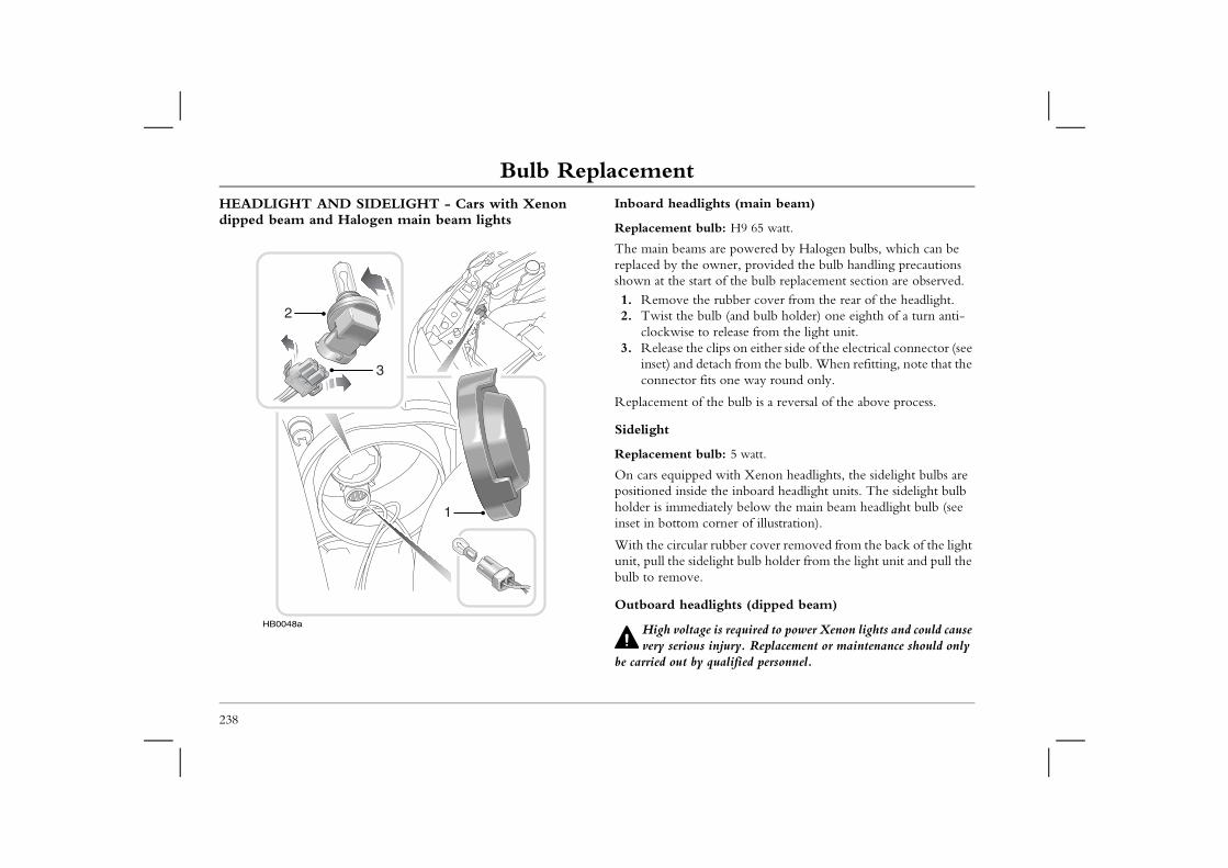
Bulb ReplacementHEADLIGHT AND SIDELIGHT - Cars with Xenon dipped beam and Halogen main beam lights
Inboard headlights (main beam)
Replacement bulb: H9 65 watt.
re powered by Halogen bulbs, which can be ner, provided the bulb handling precautions
of the bulb replacement section are observed.rubber cover from the rear of the headlight.lb (and bulb holder) one eighth of a turn anti-release from the light unit. lips on either side of the electrical connector (see ach from the bulb. When refitting, note that the s one way round only.
e bulb is a reversal of the above process.
lb: 5 watt.
with Xenon headlights, the sidelight bulbs are the inboard headlight units. The sidelight bulb tely below the main beam headlight bulb (see rner of illustration).
ubber cover removed from the back of the light ight bulb holder from the light unit and pull the
ights (dipped beam)
is required to power Xenon lights and could cause njury. Replacement or maintenance should only ualified personnel.
238
The main beams areplaced by the owshown at the start1. Remove the 2. Twist the bu
clockwise to 3. Release the c
inset) and detconnector fit
Replacement of th
Sidelight
Replacement bu
On cars equippedpositioned inside holder is immediainset in bottom co
With the circular runit, pull the sidelbulb to remove.
Outboard headl
High voltagevery serious i
be carried out by q
HB0048a
2
1
3
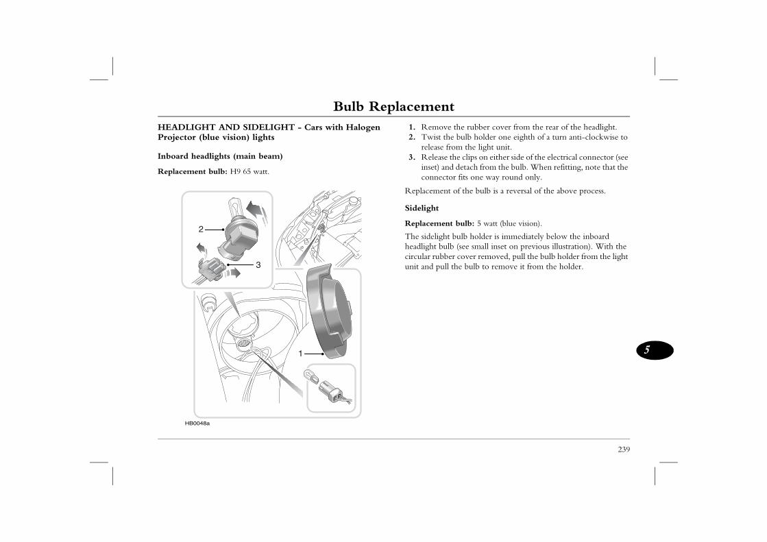
Bulb Replacement
239
5
e the rubber cover from the rear of the headlight.he bulb holder one eighth of a turn anti-clockwise to from the light unit. the clips on either side of the electrical connector (see
nd detach from the bulb. When refitting, note that the tor fits one way round only.
t of the bulb is a reversal of the above process.
nt bulb: 5 watt (blue vision).
t bulb holder is immediately below the inboard lb (see small inset on previous illustration). With the
ber cover removed, pull the bulb holder from the light ll the bulb to remove it from the holder.
HEADLIGHT AND SIDELIGHT - Cars with Halogen Projector (blue vision) lights
Inboard headlights (main beam)
Replacement bulb: H9 65 watt.
1. Remov2. Twist t
release 3. Release
inset) aconnec
Replacemen
Sidelight
Replaceme
The sidelighheadlight bucircular rubunit and pu
HB0048a
2
1
3
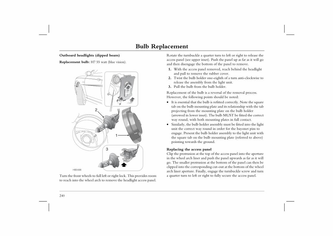
Bulb ReplacementOutboard headlights (dipped beam)
Replacement bulb: H7 55 watt (blue vision).
Rotate the turnbuckle a quarter turn to left or right to release the access panel (see upper inset). Push the panel up as far as it will go and then disengage the bottom of the panel to remove.
ess panel removed, reach behind the headlight move the rubber cover.
lb holder one-eighth of a turn anti-clockwise to sembly from the light unit. from the bulb holder.
e bulb is a reversal of the removal process. owing points should be noted: at the bulb is refitted correctly. Note the square mounting plate and its relationship with the tab the mounting plate on the bulb holder er inset). The bulb MUST be fitted the correct
th both mounting plates in full contact.ulb holder assembly must be fitted into the light t way round in order for the bayonet pins to t the bulb holder assembly to the light unit with on the bulb mounting plate (referred to above) ds the ground.
ccess paneln at the top of the access panel into the aperture liner and push the panel upwards as far as it will otrusion at the bottom of the panel can then be rresponding cut-out at the bottom of the wheel . Finally, engage the turnbuckle screw and turn eft or right to fully secure the access panel.
240
Turn the front wheels to full left or right lock. This provides room to reach into the wheel arch to remove the headlight access panel.
1. With the accand pull to re
2. Twist the burelease the as
3. Pull the bulb
Replacement of thHowever, the foll• It is essential th
tab on the bulbprojecting from(arrowed in lowway round, wi
• Similarly, the bunit the correcengage. Presenthe square tab pointing towar
Replacing the aClip the protrusioin the wheel arch go. The smaller prclipped into the coarch liner aperturea quarter turn to l
HB0498
1
3
2
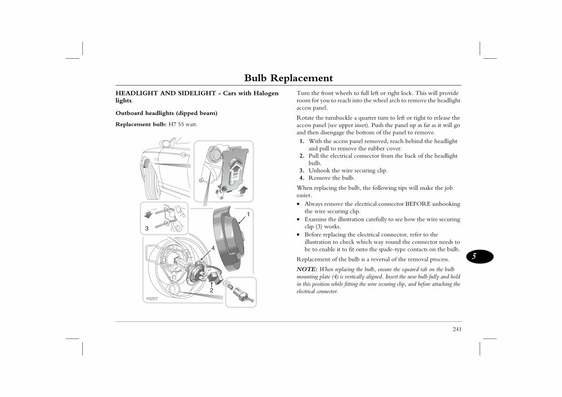
Bulb Replacement
241
5
nt wheels to full left or right lock. This will provide u to reach into the wheel arch to remove the headlight .
urnbuckle a quarter turn to left or right to release the (see upper inset). Push the panel up as far as it will go engage the bottom of the panel to remove. he access panel removed, reach behind the headlight ll to remove the rubber cover.e electrical connector from the back of the headlight
k the wire securing clip.e the bulb.
cing the bulb, the following tips will make the job
emove the electrical connector BEFORE unhooking securing clip. the illustration carefully to see how the wire securing orks.placing the electrical connector, refer to the n to check which way round the connector needs to ble it to fit onto the spade-type contacts on the bulb.
t of the bulb is a reversal of the removal process.
en replacing the bulb, ensure the squared tab on the bulb te (4) is vertically aligned. Insert the new bulb fully and hold n while fitting the wire securing clip, and before attaching the ector.
HEADLIGHT AND SIDELIGHT - Cars with Halogen lights
Outboard headlights (dipped beam)
Replacement bulb: H7 55 watt.
Turn the froroom for yoaccess panel
Rotate the taccess paneland then dis1. With t
and pu2. Pull th
bulb.3. Unhoo4. Remov
When replaeasier.• Always r
the wire• Examine
clip (3) w• Before re
illustratiobe to ena
Replacemen
NOTE: Whmounting plain this positioelectrical conn
H3257
2
3
4
1
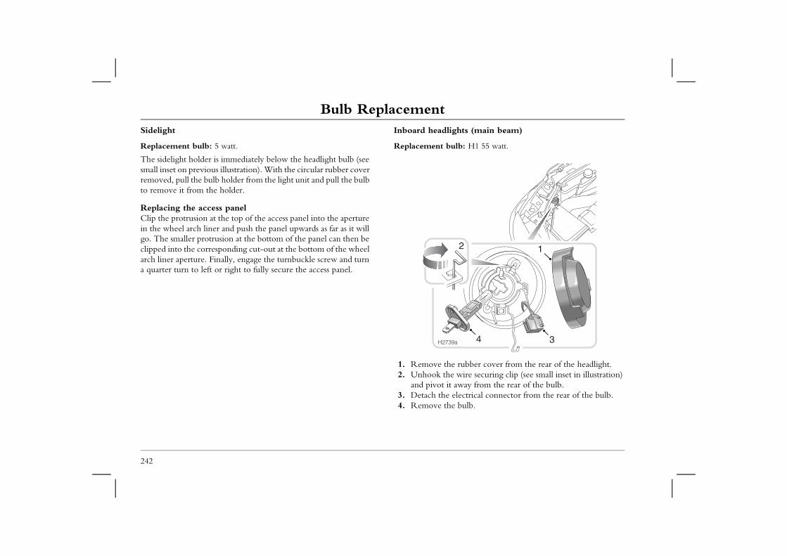
Bulb ReplacementSidelight
Replacement bulb: 5 watt.
Inboard headlights (main beam)
Replacement bulb: H1 55 watt.
rubber cover from the rear of the headlight.wire securing clip (see small inset in illustration) way from the rear of the bulb.lectrical connector from the rear of the bulb.bulb.
2
4
1
3
242
The sidelight holder is immediately below the headlight bulb (see small inset on previous illustration). With the circular rubber cover removed, pull the bulb holder from the light unit and pull the bulb to remove it from the holder.
Replacing the access panelClip the protrusion at the top of the access panel into the aperture in the wheel arch liner and push the panel upwards as far as it will go. The smaller protrusion at the bottom of the panel can then be clipped into the corresponding cut-out at the bottom of the wheel arch liner aperture. Finally, engage the turnbuckle screw and turn a quarter turn to left or right to fully secure the access panel.
1. Remove the 2. Unhook the
and pivot it a3. Detach the e4. Remove the
H2739a
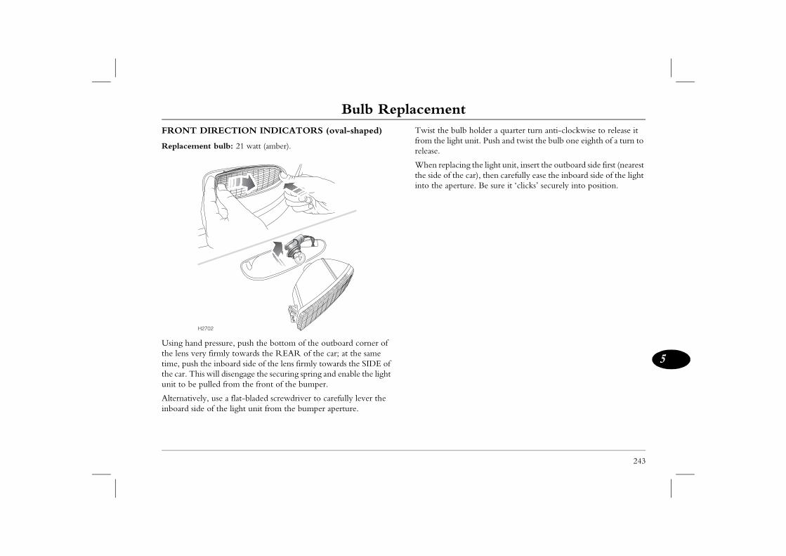
Bulb Replacement
243
5
ulb holder a quarter turn anti-clockwise to release it ht unit. Push and twist the bulb one eighth of a turn to
cing the light unit, insert the outboard side first (nearest he car), then carefully ease the inboard side of the light rture. Be sure it ‘clicks’ securely into position.
FRONT DIRECTION INDICATORS (oval-shaped)
Replacement bulb: 21 watt (amber).
Using hand pressure, push the bottom of the outboard corner of the lens very firmly towards the REAR of the car; at the same time, push the inboard side of the lens firmly towards the SIDE of the car. This will disengage the securing spring and enable the light unit to be pulled from the front of the bumper.
Alternatively, use a flat-bladed screwdriver to carefully lever the inboard side of the light unit from the bumper aperture.
Twist the bfrom the ligrelease.
When replathe side of tinto the ape
H2702
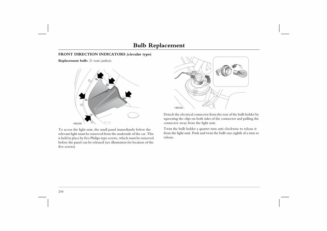
Bulb ReplacementFRONT DIRECTION INDICATORS (circular type)
Replacement bulb: 21 watt (amber).
al connector from the rear of the bulb holder by s on both sides of the connector and pulling the om the light unit.
lder a quarter turn anti-clockwise to release it . Push and twist the bulb one eighth of a turn to
244
To access the light unit, the small panel immediately below the relevant light must be removed from the underside of the car. This is held in place by five Philips type screws, which must be removed before the panel can be released (see illustration for location of the five screws).
Detach the electricsqueezing the clipconnector away fr
Twist the bulb hofrom the light unitrelease.
HB0299
HB0300
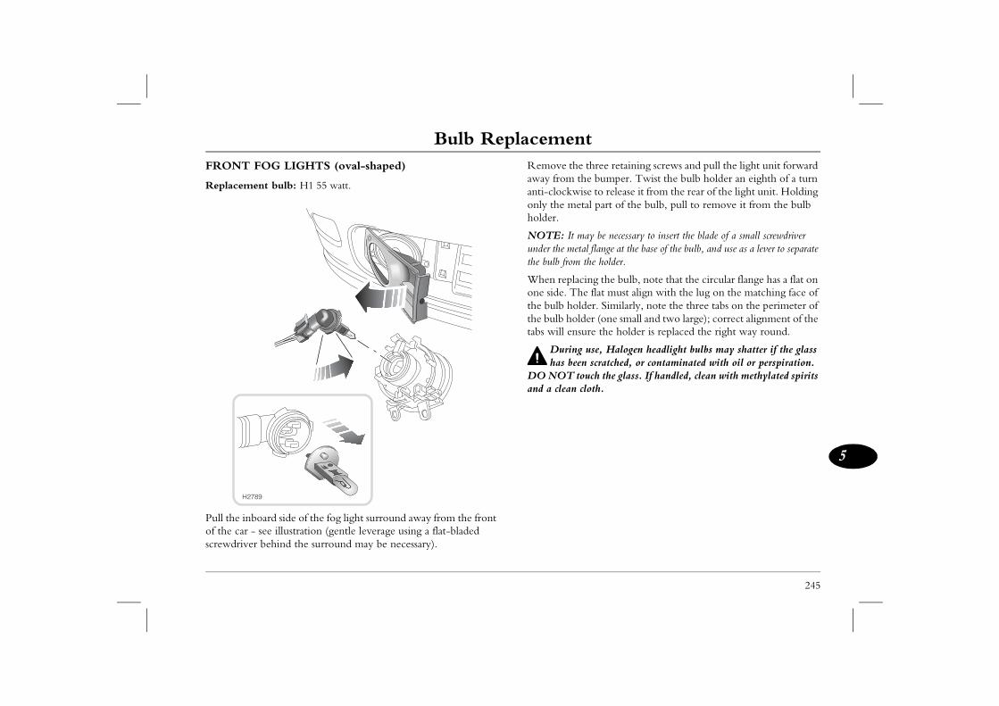
Bulb Replacement
245
5
three retaining screws and pull the light unit forward he bumper. Twist the bulb holder an eighth of a turn ise to release it from the rear of the light unit. Holding tal part of the bulb, pull to remove it from the bulb
ay be necessary to insert the blade of a small screwdriver tal flange at the base of the bulb, and use as a lever to separate the holder.
cing the bulb, note that the circular flange has a flat on e flat must align with the lug on the matching face of
lder. Similarly, note the three tabs on the perimeter of der (one small and two large); correct alignment of the ure the holder is replaced the right way round.
use, Halogen headlight bulbs may shatter if the glass n scratched, or contaminated with oil or perspiration. ouch the glass. If handled, clean with methylated spirits cloth.
FRONT FOG LIGHTS (oval-shaped)
Replacement bulb: H1 55 watt.
Pull the inboard side of the fog light surround away from the front of the car - see illustration (gentle leverage using a flat-bladed screwdriver behind the surround may be necessary).
Remove theaway from tanti-clockwonly the meholder.
NOTE: It munder the methe bulb from
When replaone side. Ththe bulb hothe bulb holtabs will ens
Duringhas bee
DO NOT tand a clean
H2789
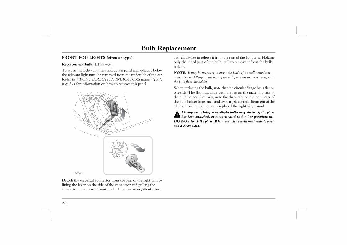
Bulb ReplacementFRONT FOG LIGHTS (circular type)
Replacement bulb: H1 55 watt.
anti-clockwise to release it from the rear of the light unit. Holding only the metal part of the bulb, pull to remove it from the bulb holder.
necessary to insert the blade of a small screwdriver ge at the base of the bulb, and use as a lever to separate lder.
e bulb, note that the circular flange has a flat on must align with the lug on the matching face of imilarly, note the three tabs on the perimeter of ne small and two large); correct alignment of the e holder is replaced the right way round.
Halogen headlight bulbs may shatter if the glass tched, or contaminated with oil or perspiration. e glass. If handled, clean with methylated spirits
246
To access the light unit, the small access panel immediately below the relevant light must be removed from the underside of the car. Refer to ‘FRONT DIRECTION INDICATORS (circular type)’, page 244 for information on how to remove this panel.
Detach the electrical connector from the rear of the light unit by lifting the lever on the side of the connector and pulling the connector downward. Twist the bulb holder an eighth of a turn
NOTE: It may beunder the metal flanthe bulb from the ho
When replacing thone side. The flat the bulb holder. Sthe bulb holder (otabs will ensure th
During use, has been scra
DO NOT touch thand a clean cloth.
HB0301
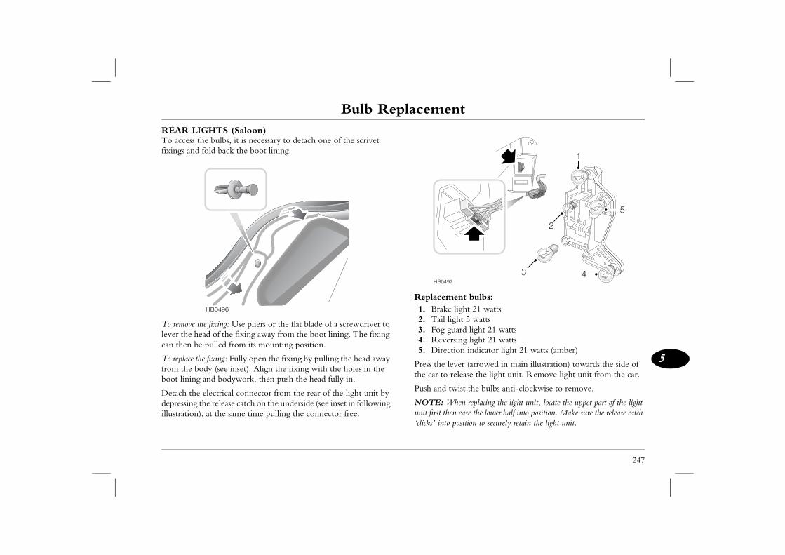
Bulb Replacement
247
5
nt bulbs:ight 21 wattsht 5 wattsard light 21 wattsing light 21 watts on indicator light 21 watts (amber)
er (arrowed in main illustration) towards the side of lease the light unit. Remove light unit from the car.
ist the bulbs anti-clockwise to remove.
en replacing the light unit, locate the upper part of the light ease the lower half into position. Make sure the release catch osition to securely retain the light unit.
1
2
43
5
REAR LIGHTS (Saloon)To access the bulbs, it is necessary to detach one of the scrivet fixings and fold back the boot lining.
To remove the fixing: Use pliers or the flat blade of a screwdriver to lever the head of the fixing away from the boot lining. The fixing can then be pulled from its mounting position.
To replace the fixing: Fully open the fixing by pulling the head away from the body (see inset). Align the fixing with the holes in the boot lining and bodywork, then push the head fully in.
Detach the electrical connector from the rear of the light unit by depressing the release catch on the underside (see inset in following illustration), at the same time pulling the connector free.
Replaceme1. Brake l2. Tail lig3. Fog gu4. Revers5. Directi
Press the levthe car to re
Push and tw
NOTE: Whunit first then‘clicks’ into p
HB0496
HB0497
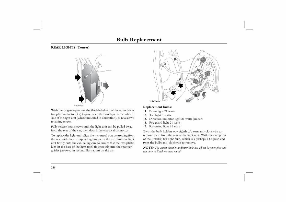
Bulb ReplacementREAR LIGHTS (Tourer)
lbs:1 wattsattsicator light 21 watts (amber)ht 21 wattsht 21 watts
lders one eighth of a turn anti-clockwise to the rear of the light unit. With the exception
l light bulb, which is a push/pull fit, push and ti-clockwise to remove.
r direction indicator bulb has off-set bayonet pins and e way round.
5
4
32
1
248
With the tailgate open, use the flat-bladed end of the screwdriver (supplied in the tool kit) to prise open the two flaps on the inboard side of the light unit (where indicated in illustration), to reveal two retaining screws.
Fully release both screws until the light unit can be pulled away from the rear of the car, then detach the electrical connector.
To replace the light unit, align the two metal pins protruding from the rear with the corresponding bushes on the car. Push the light unit firmly onto the car, taking care to ensure that the two plastic lugs (at the base of the light unit) fit smoothly into the receiver guides (arrowed in second illustration) on the car.
Replacement bu1. Brake light 22. Tail light 5 w3. Direction ind4. Fog guard lig5. Reversing lig
Twist the bulb horemove them fromof the (smaller) taitwist the bulbs an
NOTE: The ambecan only be fitted on
HB0019a
HB0041a
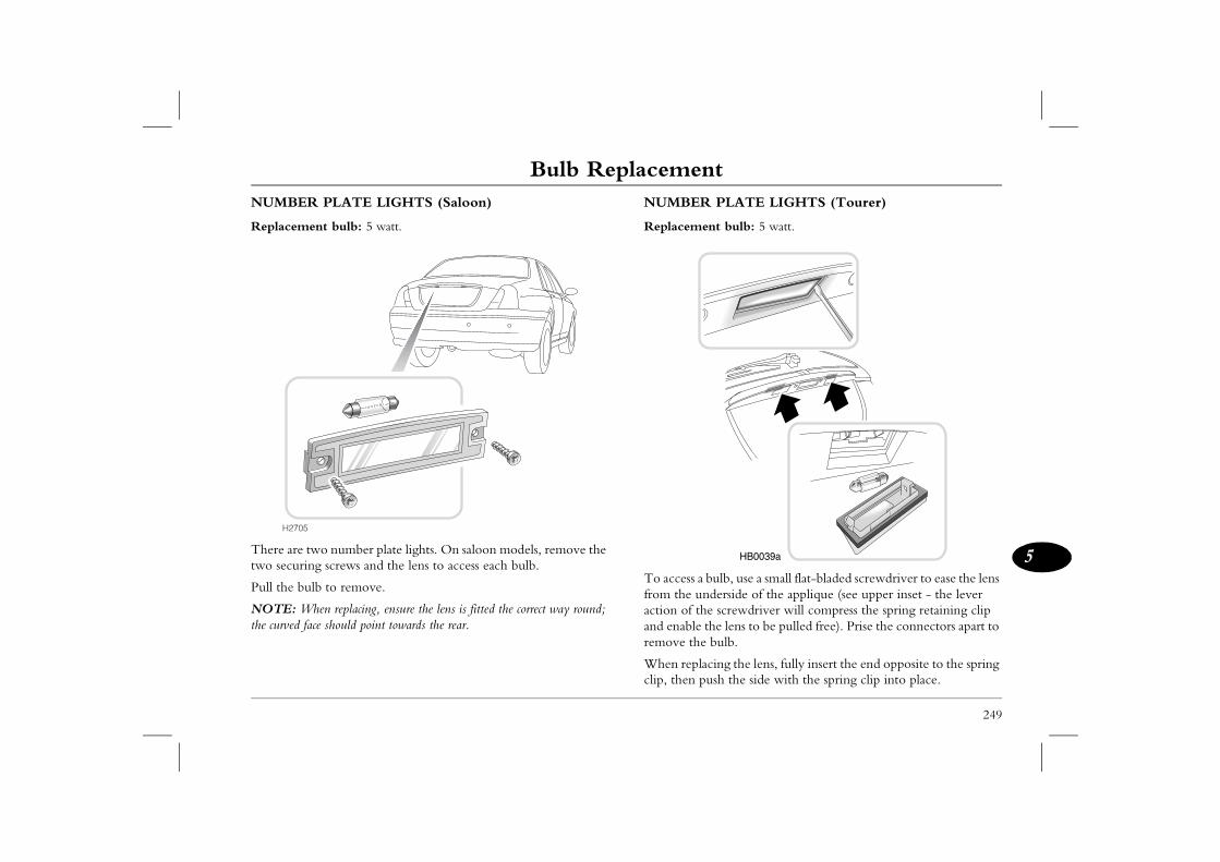
Bulb Replacement
249
5
PLATE LIGHTS (Tourer)
nt bulb: 5 watt.
ulb, use a small flat-bladed screwdriver to ease the lens derside of the applique (see upper inset - the lever e screwdriver will compress the spring retaining clip he lens to be pulled free). Prise the connectors apart to bulb.
cing the lens, fully insert the end opposite to the spring sh the side with the spring clip into place.
HB0039a
NUMBER PLATE LIGHTS (Saloon)
Replacement bulb: 5 watt.
There are two number plate lights. On saloon models, remove the two securing screws and the lens to access each bulb.
Pull the bulb to remove.
NOTE: When replacing, ensure the lens is fitted the correct way round; the curved face should point towards the rear.
NUMBER
Replaceme
To access a bfrom the unaction of thand enable tremove the
When replaclip, then pu
H2705
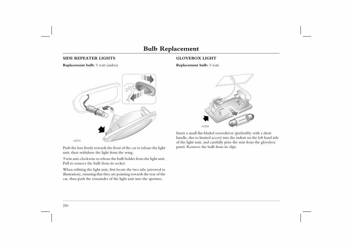
Bulb ReplacementSIDE REPEATER LIGHTS
Replacement bulb: 5 watt (amber).
GLOVEBOX LIGHT
Replacement bulb: 5 watt.
bladed screwdriver (preferably with a short ited access) into the indent on the left hand side nd carefully prise the unit from the glovebox e bulb from its clips.
784
250
Push the lens firmly towards the front of the car to release the light unit, then withdraw the light from the wing.
Twist anti-clockwise to release the bulb holder from the light unit. Pull to remove the bulb from its socket.
When refitting the light unit, first locate the two tabs (arrowed in illustration), ensuring that they are pointing towards the rear of the car, then push the remainder of the light unit into the aperture.
Insert a small flat-handle, due to limof the light unit, apanel. Remove th
H2701
H2
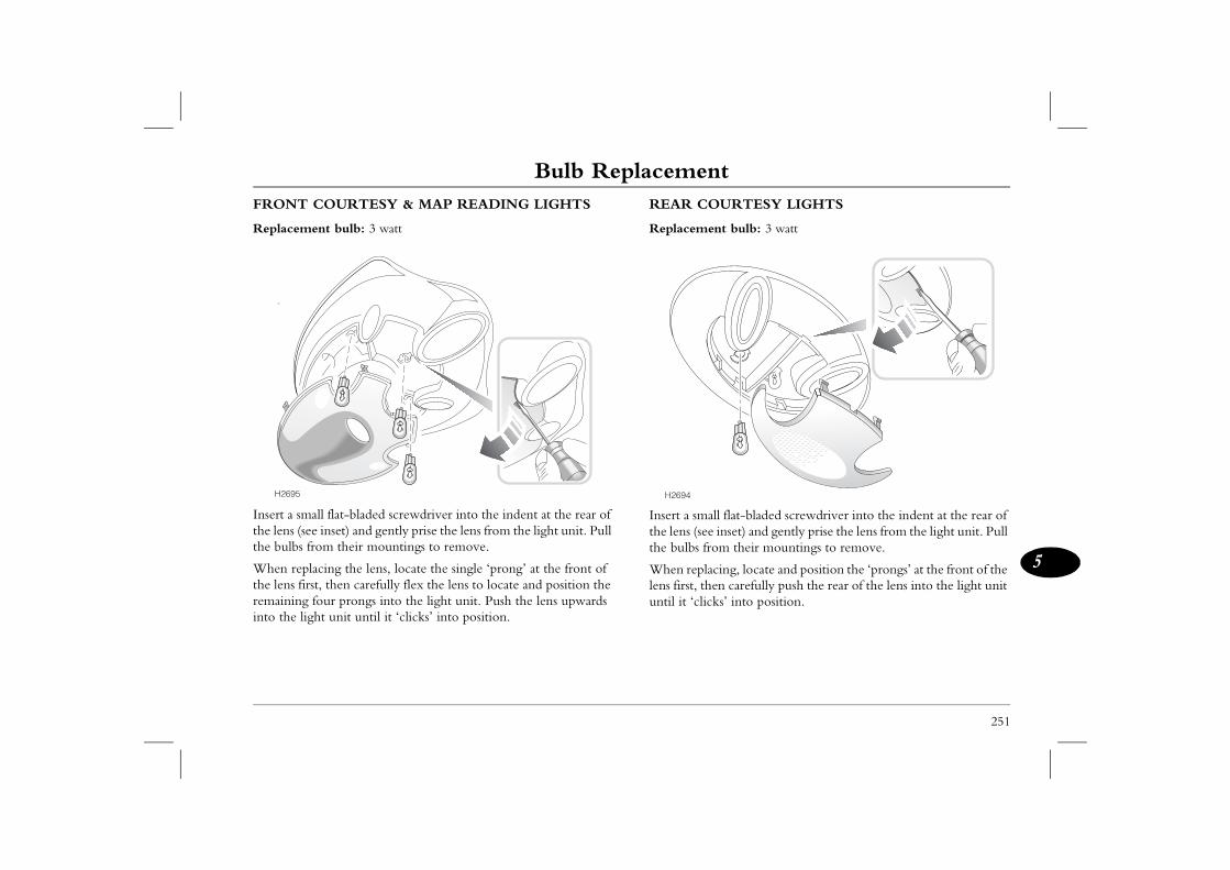
Bulb Replacement
251
5
URTESY LIGHTS
nt bulb: 3 watt
ll flat-bladed screwdriver into the indent at the rear of inset) and gently prise the lens from the light unit. Pull m their mountings to remove.
cing, locate and position the ‘prongs’ at the front of the n carefully push the rear of the lens into the light unit
ks’ into position.
FRONT COURTESY & MAP READING LIGHTS
Replacement bulb: 3 watt
Insert a small flat-bladed screwdriver into the indent at the rear of the lens (see inset) and gently prise the lens from the light unit. Pull the bulbs from their mountings to remove.
When replacing the lens, locate the single ‘prong’ at the front of the lens first, then carefully flex the lens to locate and position the remaining four prongs into the light unit. Push the lens upwards into the light unit until it ‘clicks’ into position.
REAR CO
Replaceme
Insert a smathe lens (seethe bulbs fro
When replalens first, theuntil it ‘clic
H2695 H2694
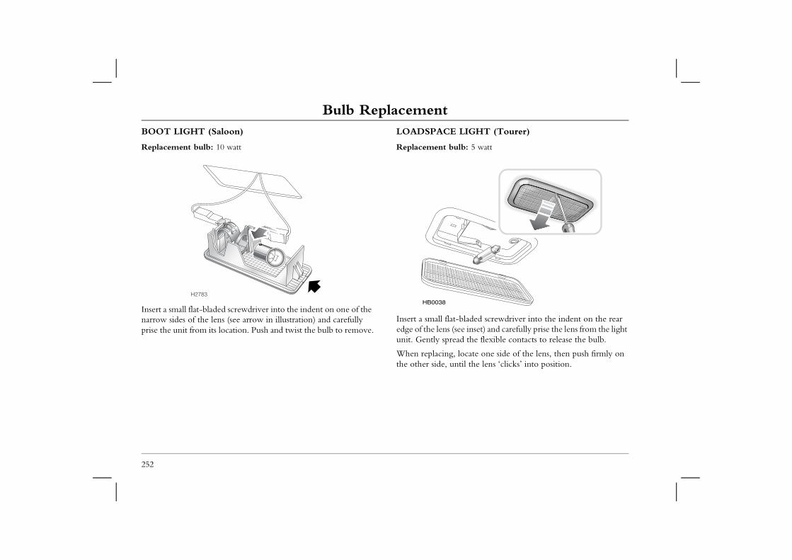
Bulb ReplacementBOOT LIGHT (Saloon)
Replacement bulb: 10 watt
LOADSPACE LIGHT (Tourer)
Replacement bulb: 5 watt
bladed screwdriver into the indent on the rear e inset) and carefully prise the lens from the light d the flexible contacts to release the bulb.
ocate one side of the lens, then push firmly on til the lens ‘clicks’ into position.
252
Insert a small flat-bladed screwdriver into the indent on one of the narrow sides of the lens (see arrow in illustration) and carefully prise the unit from its location. Push and twist the bulb to remove.
Insert a small flat-edge of the lens (seunit. Gently sprea
When replacing, lthe other side, un
H2783HB0038
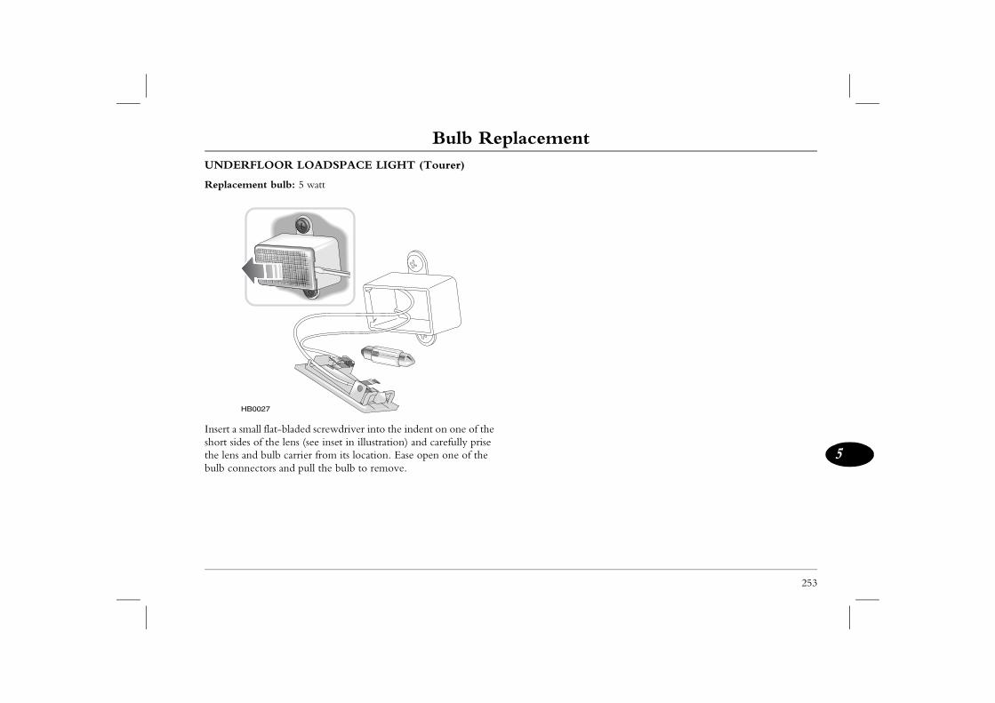
Bulb Replacement
253
5
UNDERFLOOR LOADSPACE LIGHT (Tourer)
Replacement bulb: 5 watt
Insert a small flat-bladed screwdriver into the indent on one of the short sides of the lens (see inset in illustration) and carefully prise the lens and bulb carrier from its location. Ease open one of the bulb connectors and pull the bulb to remove.
HB0027

6
Technical Data
256 Technical Data271 Fuel Consumption274 Declaration of Conformity
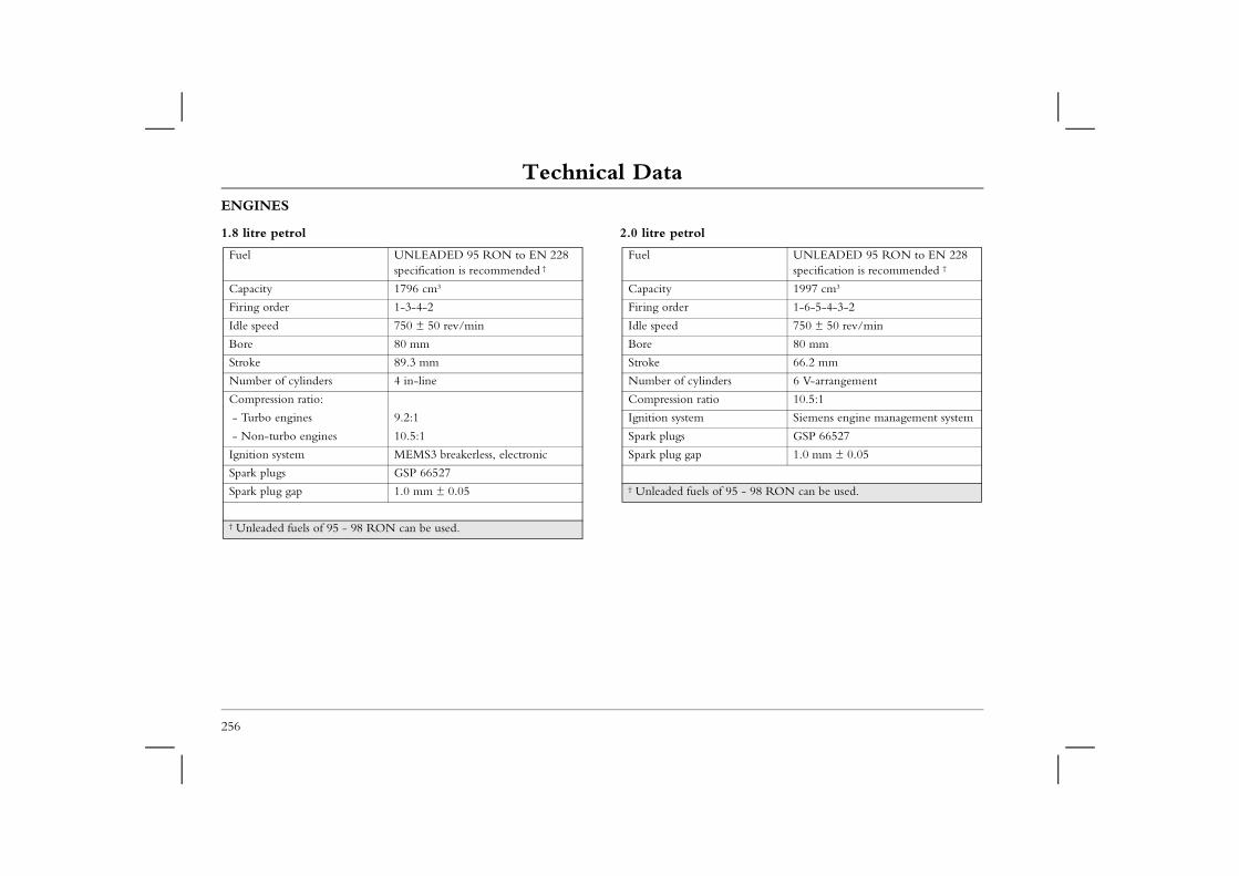
Technical DataTechnical Data Technical DataENGINES
1.8 litre petrol 2.0 litre petrol
UNLEADED 95 RON to EN 228 specification is recommended †
1997 cm3
1-6-5-4-3-2
750 ± 50 rev/min
80 mm
66.2 mm
ers 6 V-arrangement
10.5:1
Siemens engine management system
GSP 66527
1.0 mm ± 0.05
f 95 - 98 RON can be used.
256
Fuel UNLEADED 95 RON to EN 228 specification is recommended †
Capacity 1796 cm3
Firing order 1-3-4-2
Idle speed 750 ± 50 rev/min
Bore 80 mm
Stroke 89.3 mm
Number of cylinders 4 in-line
Compression ratio:
- Turbo engines 9.2:1
- Non-turbo engines 10.5:1
Ignition system MEMS3 breakerless, electronic
Spark plugs GSP 66527
Spark plug gap 1.0 mm ± 0.05
† Unleaded fuels of 95 - 98 RON can be used.
Fuel
Capacity
Firing order
Idle speed
Bore
Stroke
Number of cylind
Compression ratio
Ignition system
Spark plugs
Spark plug gap
† Unleaded fuels o
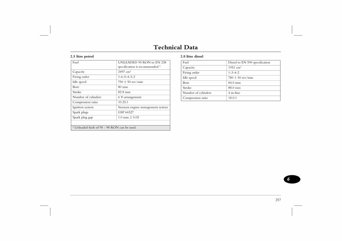
Technical Data
257
6
2.5 litre petrol 2.0 litre diesel
Diesel to EN 590 specification
1951 cm3
r 1-3-4-2
780 ± 50 rev/min
84.0 mm
88.0 mm
cylinders 4 in-line
n ratio 18.0:1
Fuel UNLEADED 95 RON to EN 228 specification is recommended †
Capacity 2497 cm3
Firing order 1-6-5-4-3-2
Idle speed 750 ± 50 rev/min
Bore 80 mm
Stroke 82.8 mm
Number of cylinders 6 V-arrangement
Compression ratio 10.25:1
Ignition system Siemens engine management system
Spark plugs GSP 66527
Spark plug gap 1.0 mm ± 0.05
† Unleaded fuels of 95 - 98 RON can be used.
Fuel
Capacity
Firing orde
Idle speed
Bore
Stroke
Number of
Compressio
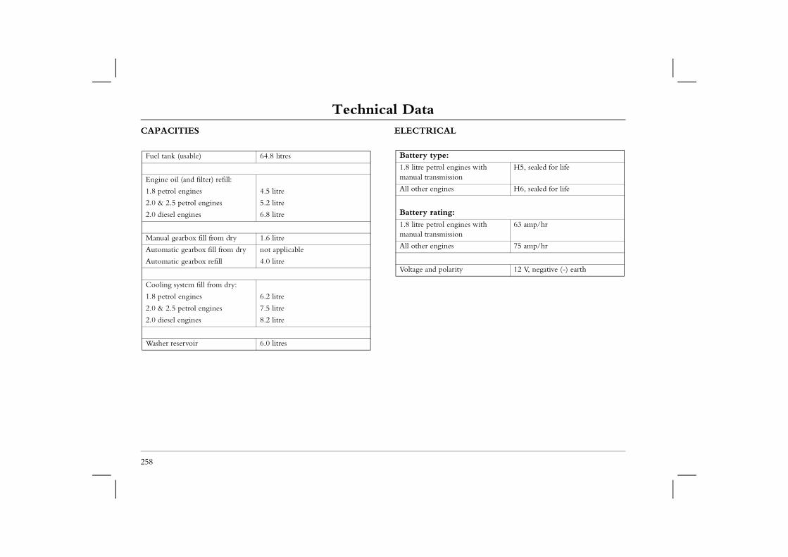
Technical DataCAPACITIES ELECTRICAL
ines with n
H5, sealed for life
H6, sealed for life
ines with n
63 amp/hr
75 amp/hr
ty 12 V, negative (-) earth
258
Fuel tank (usable) 64.8 litres
Engine oil (and filter) refill:
1.8 petrol engines 4.5 litre
2.0 & 2.5 petrol engines 5.2 litre
2.0 diesel engines 6.8 litre
Manual gearbox fill from dry 1.6 litre
Automatic gearbox fill from dry not applicable
Automatic gearbox refill 4.0 litre
Cooling system fill from dry:
1.8 petrol engines 6.2 litre
2.0 & 2.5 petrol engines 7.5 litre
2.0 diesel engines 8.2 litre
Washer reservoir 6.0 litres
Battery type:
1.8 litre petrol engmanual transmissio
All other engines
Battery rating:
1.8 litre petrol engmanual transmissio
All other engines
Voltage and polari
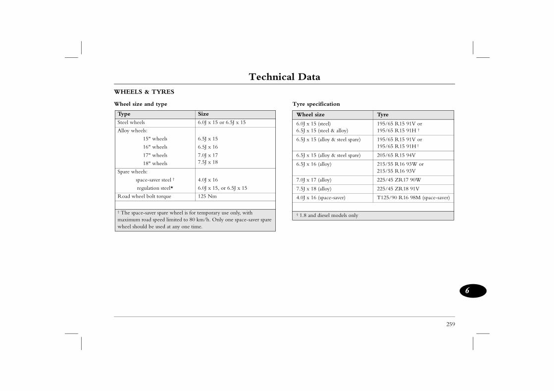
Technical Data
259
6
ication
e Tyre
teel)teel & alloy)
195/65 R15 91V or 195/65 R15 91H †
lloy & steel spare) 195/65 R15 91V or 195/65 R15 91H †
lloy & steel spare) 205/65 R15 94V
lloy) 215/55 R16 93W or 215/55 R16 93V
lloy) 225/45 ZR17 90W
lloy) 225/45 ZR18 91V
pace-saver) T125/90 R16 98M (space-saver)
esel models only
WHEELS & TYRES
Wheel size and type Tyre specif
Type Size
Steel wheels 6.0J x 15 or 6.5J x 15
Alloy wheels:
15" wheels 6.5J x 15
16" wheels 6.5J x 16
17" wheels
18" wheels
7.0J x 177.5J x 18
Spare wheels:
space-saver steel † 4.0J x 16
regulation steel* 6.0J x 15, or 6.5J x 15
Road wheel bolt torque 125 Nm
† The space-saver spare wheel is for temporary use only, with maximum road speed limited to 80 km/h. Only one space-saver spare wheel should be used at any one time.
Wheel siz
6.0J x 15 (s6.5J x 15 (s
6.5J x 15 (a
6.5J x 15 (a
6.5J x 16 (a
7.0J x 17 (a
7.5J x 18 (a
4.0J x 16 (s
† 1.8 and di
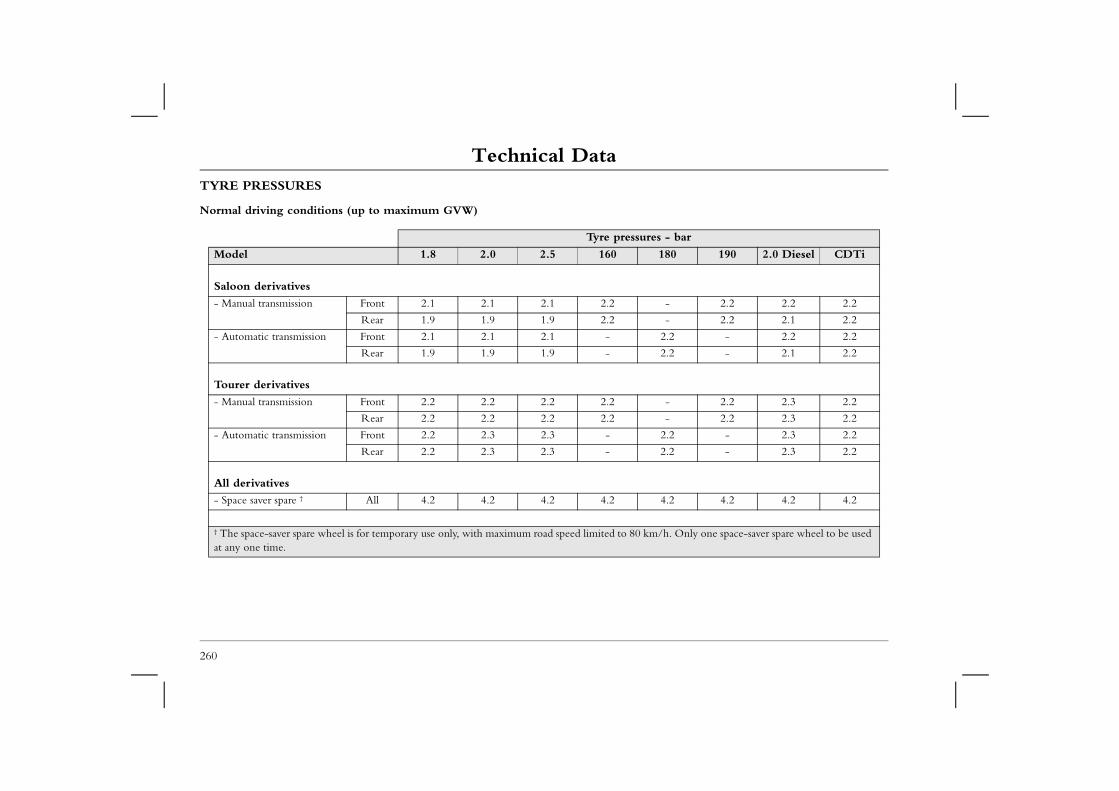
Technical DataTYRE PRESSURES
Normal driving conditions (up to maximum GVW)
es - bar
180 190 2.0 Diesel CDTi
- 2.2 2.2 2.2
- 2.2 2.1 2.2
2.2 - 2.2 2.2
2.2 - 2.1 2.2
- 2.2 2.3 2.2
- 2.2 2.3 2.2
2.2 - 2.3 2.2
2.2 - 2.3 2.2
4.2 4.2 4.2 4.2
m/h. Only one space-saver spare wheel to be used
260
Tyre pressur
Model 1.8 2.0 2.5 160
Saloon derivatives
- Manual transmission Front 2.1 2.1 2.1 2.2
Rear 1.9 1.9 1.9 2.2
- Automatic transmission Front 2.1 2.1 2.1 -
Rear 1.9 1.9 1.9 -
Tourer derivatives
- Manual transmission Front 2.2 2.2 2.2 2.2
Rear 2.2 2.2 2.2 2.2
- Automatic transmission Front 2.2 2.3 2.3 -
Rear 2.2 2.3 2.3 -
All derivatives
- Space saver spare † All 4.2 4.2 4.2 4.2
† The space-saver spare wheel is for temporary use only, with maximum road speed limited to 80 kat any one time.
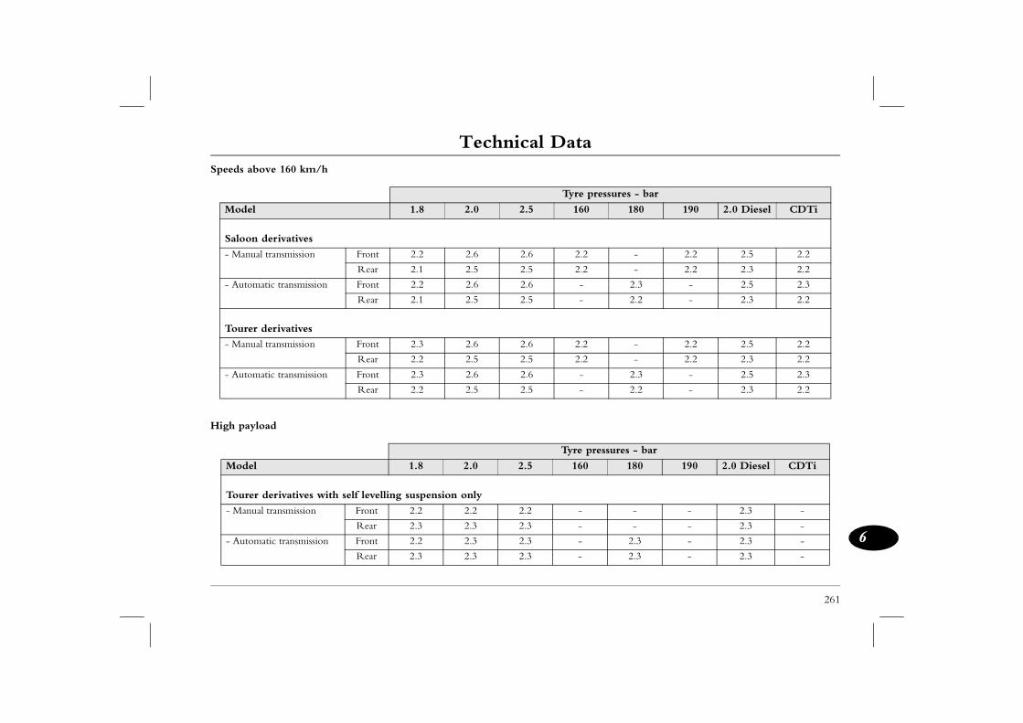
Technical Data
261
6
Speeds above 160 km/h
ressures - bar
180 190 2.0 Diesel CDTi
- 2.2 2.5 2.2
- 2.2 2.3 2.2
2.3 - 2.5 2.3
2.2 - 2.3 2.2
- 2.2 2.5 2.2
- 2.2 2.3 2.2
2.3 - 2.5 2.3
2.2 - 2.3 2.2
ressures - bar
180 190 2.0 Diesel CDTi
- - 2.3 -
- - 2.3 -
2.3 - 2.3 -
2.3 - 2.3 -
High payload
Tyre p
Model 1.8 2.0 2.5 160
Saloon derivatives
- Manual transmission Front 2.2 2.6 2.6 2.2
Rear 2.1 2.5 2.5 2.2
- Automatic transmission Front 2.2 2.6 2.6 -
Rear 2.1 2.5 2.5 -
Tourer derivatives
- Manual transmission Front 2.3 2.6 2.6 2.2
Rear 2.2 2.5 2.5 2.2
- Automatic transmission Front 2.3 2.6 2.6 -
Rear 2.2 2.5 2.5 -
Tyre p
Model 1.8 2.0 2.5 160
Tourer derivatives with self levelling suspension only
- Manual transmission Front 2.2 2.2 2.2 -
Rear 2.3 2.3 2.3 -
- Automatic transmission Front 2.2 2.3 2.3 -
Rear 2.3 2.3 2.3 -
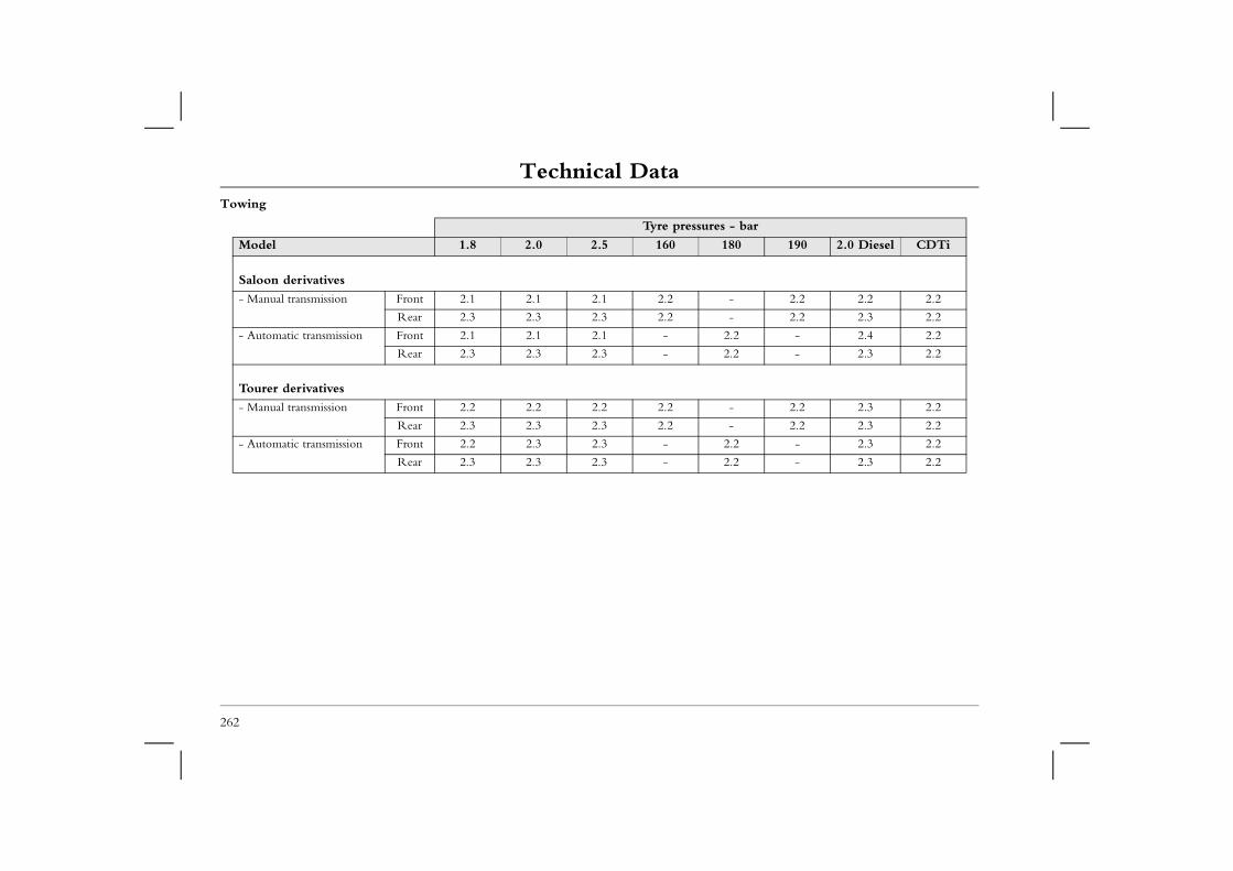
Technical DataTowing
Tyre pressures - bar
180 190 2.0 Diesel CDTi
- 2.2 2.2 2.2
- 2.2 2.3 2.2
2.2 - 2.4 2.2
2.2 - 2.3 2.2
- 2.2 2.3 2.2
- 2.2 2.3 2.2
2.2 - 2.3 2.2
2.2 - 2.3 2.2
262
Model 1.8 2.0 2.5 160
Saloon derivatives
- Manual transmission Front 2.1 2.1 2.1 2.2
Rear 2.3 2.3 2.3 2.2
- Automatic transmission Front 2.1 2.1 2.1 -
Rear 2.3 2.3 2.3 -
Tourer derivatives
- Manual transmission Front 2.2 2.2 2.2 2.2
Rear 2.3 2.3 2.3 2.2
- Automatic transmission Front 2.2 2.3 2.3 -
Rear 2.3 2.3 2.3 -
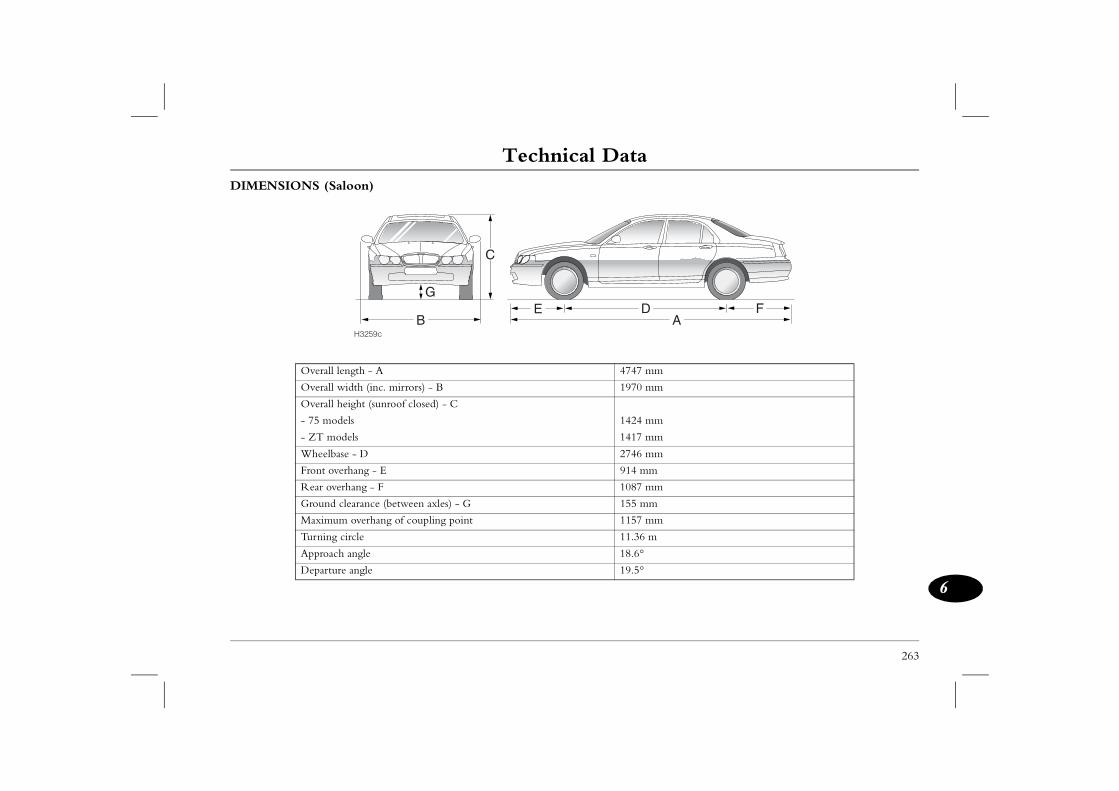
Technical Data
263
6
AF
m
m
m
m
m
m
m
m
m
m
DIMENSIONS (Saloon)
H3259c
BDE
G
C
Overall length - A 4747 m
Overall width (inc. mirrors) - B 1970 m
Overall height (sunroof closed) - C
- 75 models 1424 m
- ZT models 1417 m
Wheelbase - D 2746 m
Front overhang - E 914 m
Rear overhang - F 1087 m
Ground clearance (between axles) - G 155 m
Maximum overhang of coupling point 1157 m
Turning circle 11.36
Approach angle 18.6°
Departure angle 19.5°
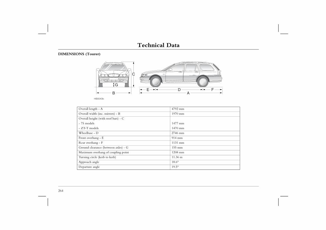
Technical DataDIMENSIONS (Tourer)
F
264
ABDE
G
HB0043b
C
Overall length - A 4792 mm
Overall width (inc. mirrors) - B 1970 mm
Overall height (with roof bars) - C
- 75 models 1477 mm
- ZT-T models 1470 mm
Wheelbase - D 2746 mm
Front overhang - E 914 mm
Rear overhang - F 1131 mm
Ground clearance (between axles) - G 155 mm
Maximum overhang of coupling point 1208 mm
Turning circle (kerb to kerb) 11.36 m
Approach angle 18.6°
Departure angle 19.5°
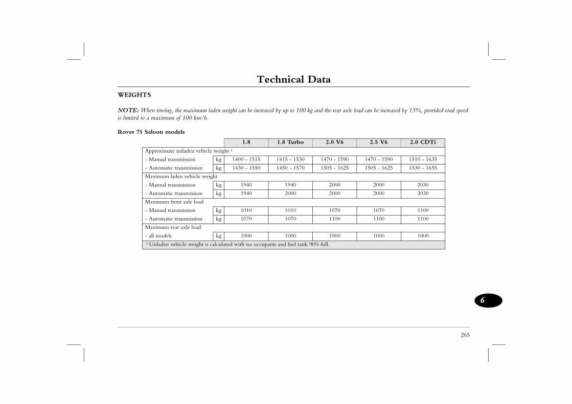
Technical Data
265
6
rear axle load can be increased by 15%, provided road speed
V6 2.5 V6 2.0 CDTi
- 1590 1470 - 1590 1510 - 1635
- 1625 1505 - 1625 1530 - 1655
000 2000 2030
000 2000 2030
070 1070 1100
100 1100 1100
000 1000 1000
WEIGHTS
NOTE: When towing, the maximum laden weight can be increased by up to 100 kg and theis limited to a maximum of 100 km/h.
Rover 75 Saloon models
1.8 1.8 Turbo 2.0
Approximate unladen vehicle weight †
- Manual transmission kg 1400 - 1515 1415 - 1530 1470
- Automatic transmission kg 1430 - 1550 1450 - 1570 1505
Maximum laden vehicle weight
- Manual transmission kg 1940 1940 2
- Automatic transmission kg 1940 2000 2
Maximum front axle load
- Manual transmission kg 1010 1010 1
- Automatic transmission kg 1070 1070 1
Maximum rear axle load
- all models kg 1000 1000 1 † Unladen vehicle weight is calculated with no occupants and fuel tank 90% full.
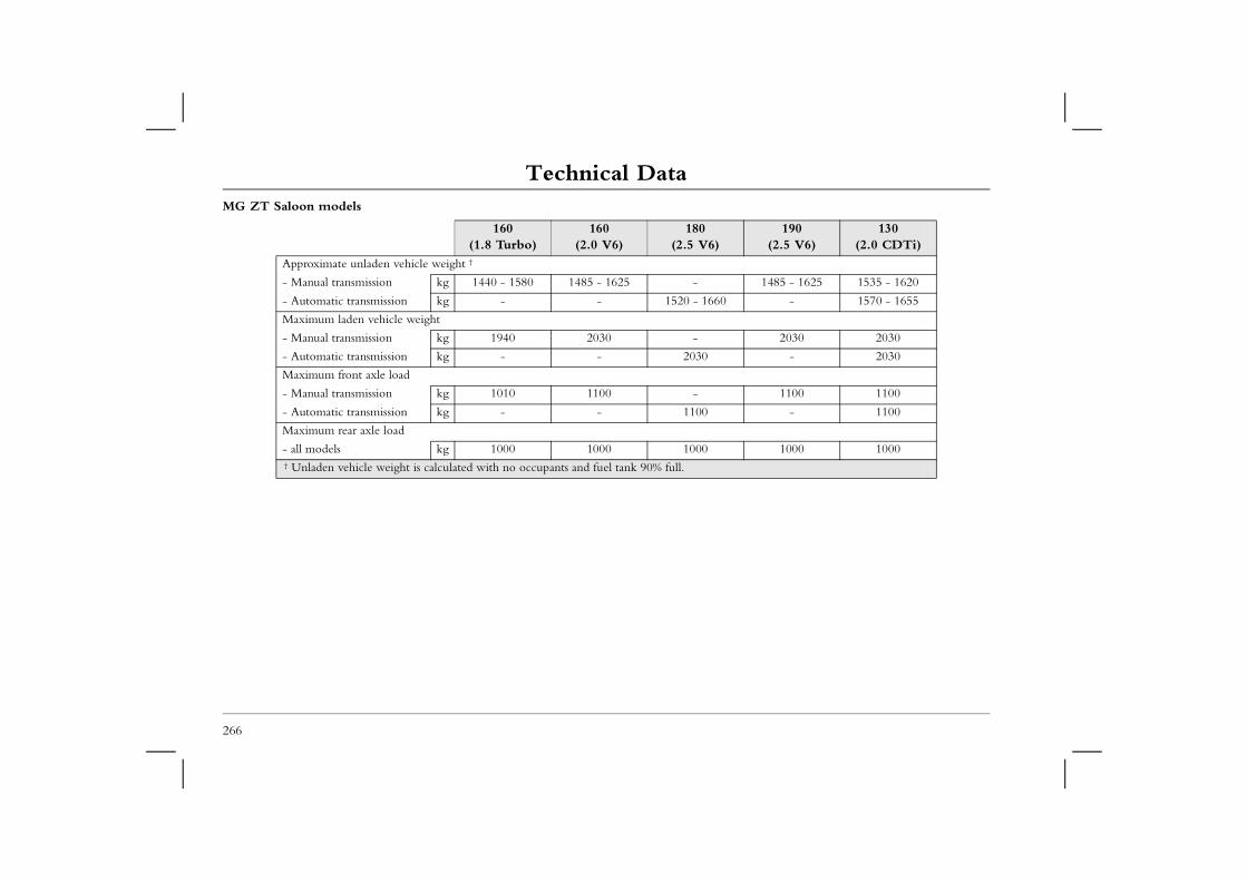
Technical DataMG ZT Saloon models
160 160 180 190(2.5 V6)
130 (2.0 CDTi)
1485 - 1625 1535 - 1620
- 1570 - 1655
2030 2030
- 2030
1100 1100
- 1100
1000 1000
266
(1.8 Turbo) (2.0 V6) (2.5 V6)
Approximate unladen vehicle weight †
- Manual transmission kg 1440 - 1580 1485 - 1625 -
- Automatic transmission kg - - 1520 - 1660
Maximum laden vehicle weight
- Manual transmission kg 1940 2030 -
- Automatic transmission kg - - 2030
Maximum front axle load
- Manual transmission kg 1010 1100 -
- Automatic transmission kg - - 1100
Maximum rear axle load
- all models kg 1000 1000 1000 † Unladen vehicle weight is calculated with no occupants and fuel tank 90% full.
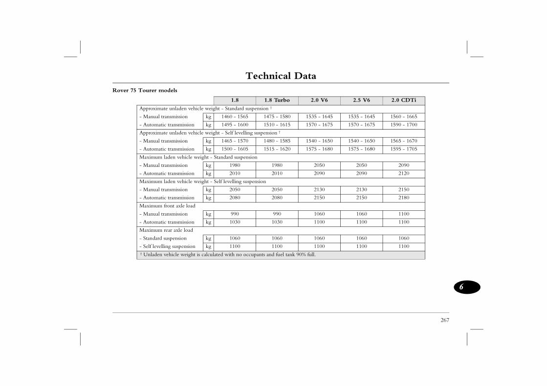
Technical Data
267
6
Rover 75 Tourer models
V6 2.5 V6 2.0 CDTi
- 1645 1535 - 1645 1560 - 1665
- 1675 1570 - 1675 1590 - 1700
- 1650 1540 - 1650 1565 - 1670
- 1680 1575 - 1680 1595 - 1705
050 2050 2090
090 2090 2120
130 2130 2150
150 2150 2180
060 1060 1100
100 1100 1100
060 1060 1060
100 1100 1100
1.8 1.8 Turbo 2.0
Approximate unladen vehicle weight - Standard suspension †
- Manual transmission kg 1460 - 1565 1475 - 1580 1535
- Automatic transmission kg 1495 - 1600 1510 - 1615 1570
Approximate unladen vehicle weight - Self levelling suspension †
- Manual transmission kg 1465 - 1570 1480 - 1585 1540
- Automatic transmission kg 1500 - 1605 1515 - 1620 1575
Maximum laden vehicle weight - Standard suspension
- Manual transmission kg 1980 1980 2
- Automatic transmission kg 2010 2010 2
Maximum laden vehicle weight - Self levelling suspension
- Manual transmission kg 2050 2050 2
- Automatic transmission kg 2080 2080 2
Maximum front axle load
- Manual transmission kg 990 990 1
- Automatic transmission kg 1030 1030 1
Maximum rear axle load
- Standard suspension kg 1060 1060 1
- Self levelling suspension kg 1100 1100 1 † Unladen vehicle weight is calculated with no occupants and fuel tank 90% full.

Technical DataMG ZT Tourer models
160 160 180 190 (2.5 V6)
130 (2.0 CDTi)
1550 - 1680 1585 - 1670
- 1620 - 1705
2090 2090
- 2120
1100 1100
- 1100
1060 1060
268
(1.8 Turbo) (2.0 V6) (2.5 V6)
Approximate unladen vehicle weight †
- Manual transmission kg 1505 - 1635 1550 - 1680 -
- Automatic transmission kg - - 1585 - 1715
Maximum laden vehicle weight
- Manual transmission kg 2010 2090 -
- Automatic transmission kg - - 2090
Maximum front axle load
- Manual transmission kg 1030 1100 -
- Automatic transmission kg - - 1100
Maximum rear axle load
- Standard suspension kg 1060 1060 1060 † Unladen vehicle weight is calculated with no occupants and fuel tank 90% full.
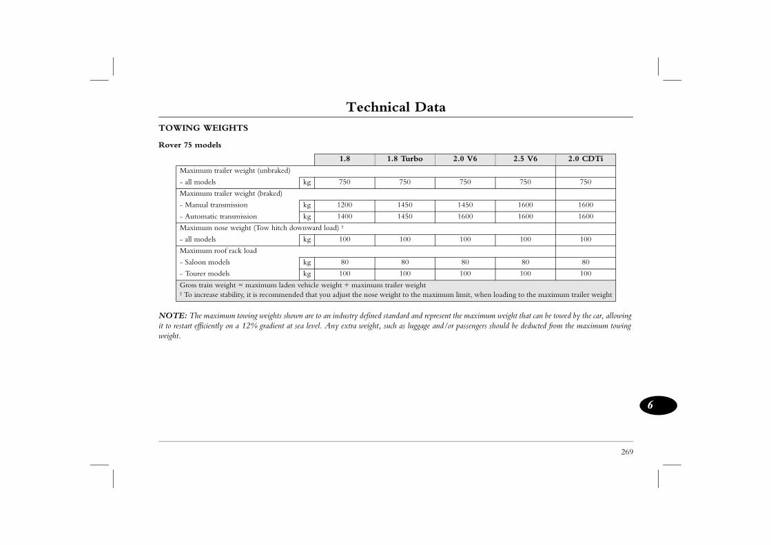
Technical Data
269
6
t the maximum weight that can be towed by the car, allowing or passengers should be deducted from the maximum towing
2.0 V6 2.5 V6 2.0 CDTi
750 750 750
1450 1600 1600
1600 1600 1600
100 100 100
80 80 80
100 100 100
m limit, when loading to the maximum trailer weight
TOWING WEIGHTS
Rover 75 models
NOTE: The maximum towing weights shown are to an industry defined standard and represenit to restart efficiently on a 12% gradient at sea level. Any extra weight, such as luggage and/weight.
1.8 1.8 Turbo
Maximum trailer weight (unbraked)
- all models kg 750 750
Maximum trailer weight (braked)
- Manual transmission kg 1200 1450
- Automatic transmission kg 1400 1450
Maximum nose weight (Tow hitch downward load) †
- all models kg 100 100
Maximum roof rack load
- Saloon models kg 80 80
- Tourer models kg 100 100
Gross train weight = maximum laden vehicle weight + maximum trailer weight† To increase stability, it is recommended that you adjust the nose weight to the maximu
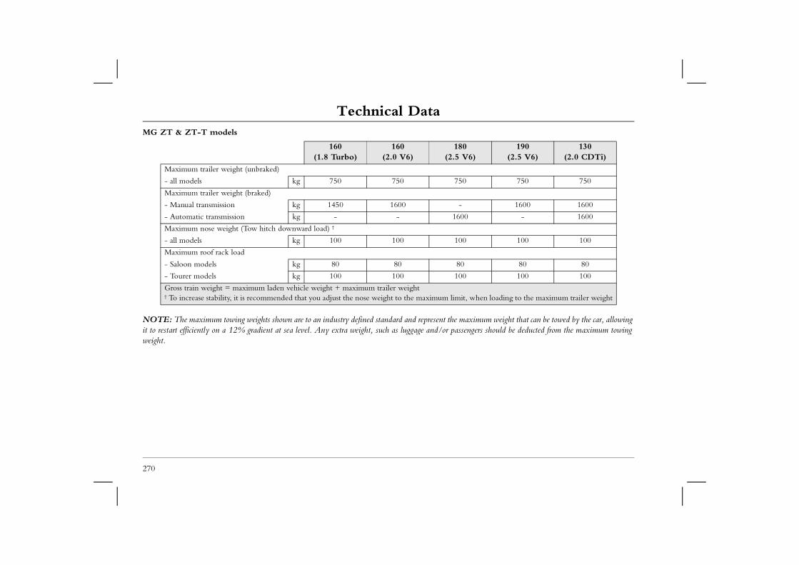
Technical DataMG ZT & ZT-T models
aximum weight that can be towed by the car, allowing engers should be deducted from the maximum towing
160 160 180 6)
190 (2.5 V6)
130 (2.0 CDTi)
750 750
1600 1600
0 - 1600
100 100
80 80
100 100
t, when loading to the maximum trailer weight
270
NOTE: The maximum towing weights shown are to an industry defined standard and represent the mit to restart efficiently on a 12% gradient at sea level. Any extra weight, such as luggage and/or passweight.
(1.8 Turbo) (2.0 V6) (2.5 V
Maximum trailer weight (unbraked)
- all models kg 750 750 750
Maximum trailer weight (braked)
- Manual transmission kg 1450 1600 -
- Automatic transmission kg - - 160
Maximum nose weight (Tow hitch downward load) †
- all models kg 100 100 100
Maximum roof rack load
- Saloon models kg 80 80 80
- Tourer models kg 100 100 100
Gross train weight = maximum laden vehicle weight + maximum trailer weight† To increase stability, it is recommended that you adjust the nose weight to the maximum limi
Fuel Consumption
271
6
Fuel Consumption
rocedure (the new EC test procedure from Directive on (Amendment) Order 1996. Under normal use, a procedure, depending on driving technique, road and
ions, decelerations and periods of steady speed driving average speed of 19 km/h.
ately half of the test comprises steady-speed driving, ing. The maximum test speed is 120 km/h and the
ich has been weighted to take account of the different
rocedure previously required by The Passenger Car Fuel ould differ if the same car were subjected to both tests.
FUEL CONSUMPTIONThe fuel consumption figures shown have been calculated using a standard testing p99/100/EC), and produced in accordance with The Passenger Car Fuel Consumpticar's actual fuel consumption figures may differ from those achieved through the test traffic conditions, environmental factors, vehicle load and condition.
Urban cycle The urban test cycle is carried out from a cold start and consists of a series of acceleratand engine idling. The maximum speed attained during the test is 50 km/h with an
Extra-urban cycleThe extra urban test cycle is carried out immediately after the urban test. Approximwhile the remainder consists of a series of accelerations, decelerations and engine idlaverage speed 63 km/h. The test is carried out over a distance of 7 km.
Combined The combined figure is an average of the urban and extra-urban test cycle results, whdistances covered during the two tests.
NOTE: These figures should not be compared with figures produced using the ECE/EEC pConsumption Order 1983. Because of the changes in test procedure, even the urban figures w
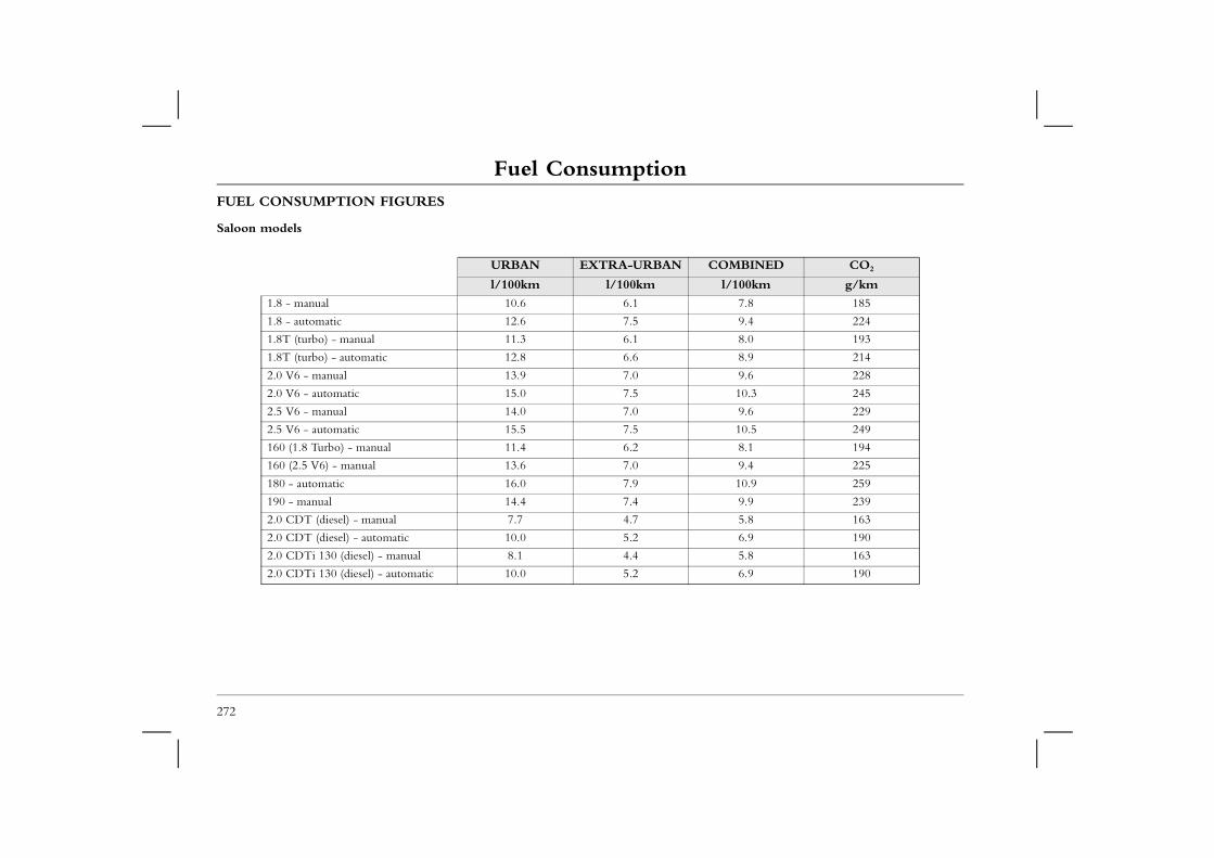
Fuel ConsumptionFUEL CONSUMPTION FIGURES
Saloon models
COMBINED CO2
l/100km g/km
7.8 185
9.4 224
8.0 193
8.9 214
9.6 228
10.3 245
9.6 229
10.5 249
8.1 194
9.4 225
10.9 259
9.9 239
5.8 163
6.9 190
5.8 163
6.9 190
272
URBAN EXTRA-URBAN
l/100km l/100km
1.8 - manual 10.6 6.1
1.8 - automatic 12.6 7.5
1.8T (turbo) - manual 11.3 6.1
1.8T (turbo) - automatic 12.8 6.6
2.0 V6 - manual 13.9 7.0
2.0 V6 - automatic 15.0 7.5
2.5 V6 - manual 14.0 7.0
2.5 V6 - automatic 15.5 7.5
160 (1.8 Turbo) - manual 11.4 6.2
160 (2.5 V6) - manual 13.6 7.0
180 - automatic 16.0 7.9
190 - manual 14.4 7.4
2.0 CDT (diesel) - manual 7.7 4.7
2.0 CDT (diesel) - automatic 10.0 5.2
2.0 CDTi 130 (diesel) - manual 8.1 4.4
2.0 CDTi 130 (diesel) - automatic 10.0 5.2
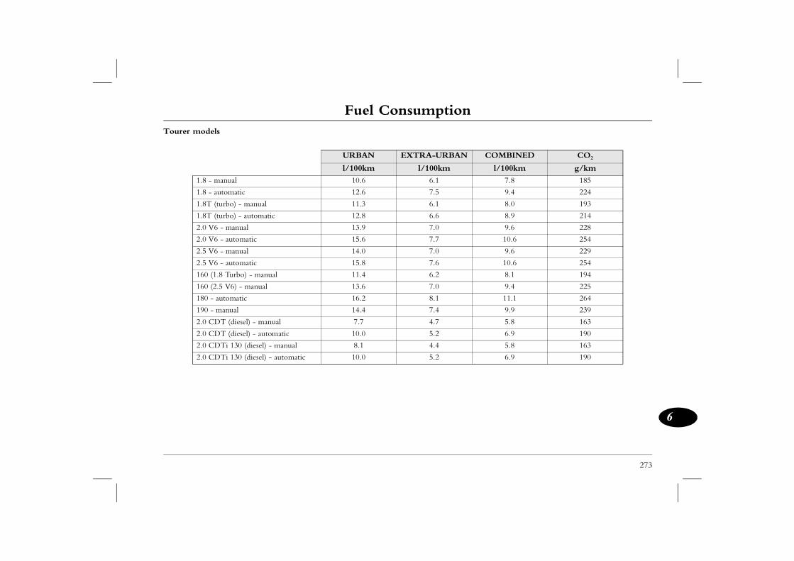
Fuel Consumption
273
6
Tourer models
N COMBINED CO2
l/100km g/km
7.8 185
9.4 224
8.0 193
8.9 214
9.6 228
10.6 254
9.6 229
10.6 254
8.1 194
9.4 225
11.1 264
9.9 239
5.8 163
6.9 190
5.8 163
6.9 190
URBAN EXTRA-URBA
l/100km l/100km
1.8 - manual 10.6 6.1
1.8 - automatic 12.6 7.5
1.8T (turbo) - manual 11.3 6.1
1.8T (turbo) - automatic 12.8 6.6
2.0 V6 - manual 13.9 7.0
2.0 V6 - automatic 15.6 7.7
2.5 V6 - manual 14.0 7.0
2.5 V6 - automatic 15.8 7.6
160 (1.8 Turbo) - manual 11.4 6.2
160 (2.5 V6) - manual 13.6 7.0
180 - automatic 16.2 8.1
190 - manual 14.4 7.4
2.0 CDT (diesel) - manual 7.7 4.7
2.0 CDT (diesel) - automatic 10.0 5.2
2.0 CDTi 130 (diesel) - manual 8.1 4.4
2.0 CDTi 130 (diesel) - automatic 10.0 5.2
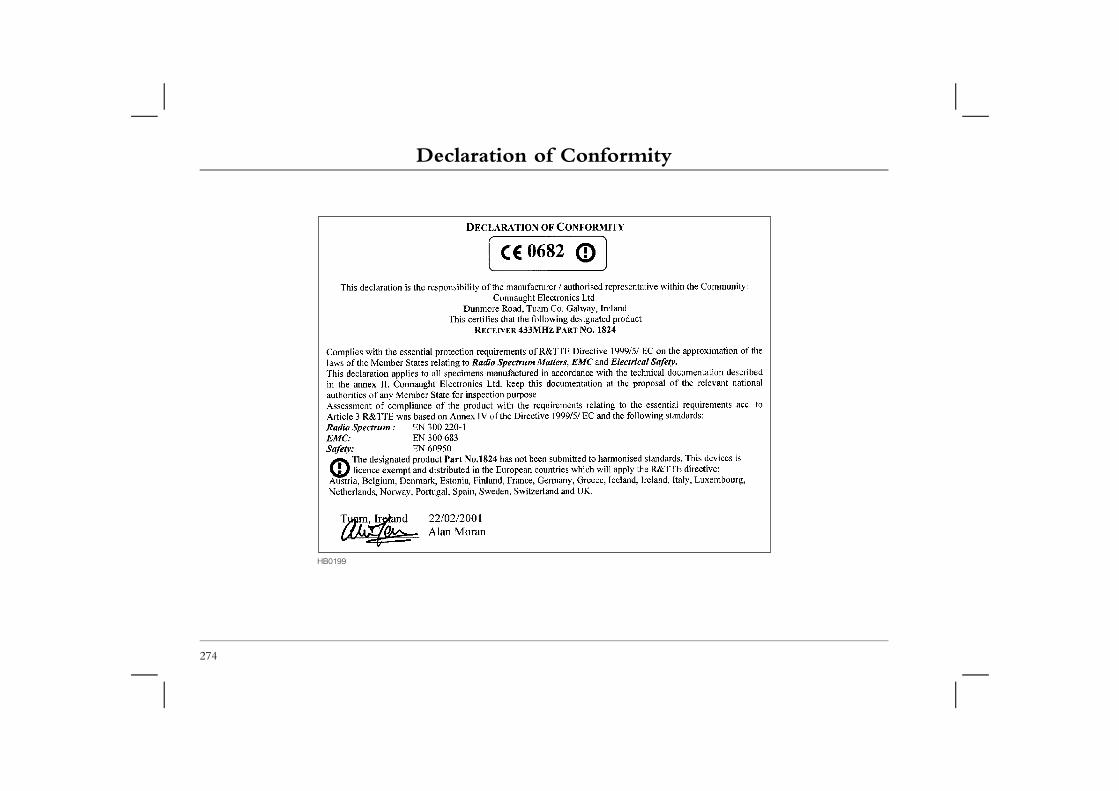
Declaration of ConformityDeclaration of Conformity
274
HB0199
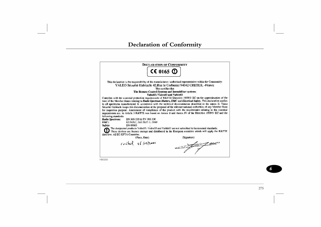
Declaration of Conformity
275
6
HB0200

Index
i
B........................................................................ 258ndset ................................................................ 16hicle ............................................................... 200ging ............................................................... 202k ................................................................... 200
onnection ....................................................... 201acement - handset ............................................. 16ty .................................................................... 200C) .................................................................... 44ter) .................................................................. 39er ................................................................... 212ning ................................................................ 188les ................................................................... 216ing) ................................................................... 12ulb ................................................................. 252........................................................................ 196bulb - Saloon .................................................. 247bulb - Tourer ................................................. 248ear indicator .................................................. 115
ing light .......................................................... 115............................................................... 114, 196ment ............................................................. 237
AABS (Anti-lock braking) ................................................... 116ABS warning light ............................................................ 117Accessories ....................................................................... 214Air conditioning .......................................................... 40, 42Air distribution ................................................................... 39Air distribution control ....................................................... 44Air recirculation .......................................................... 39, 44Air vents ............................................................................ 38Airbag SRS ........................................................................ 27Airbag SRS service information .......................................... 32Airbag SRS warning light ................................................... 31Airbags - side ..................................................................... 30Airbags - side head ............................................................. 31Alarm system ........................................................................ 7Alarm system indicator light ................................................. 9Anti-freeze ....................................................................... 195Anti-lock braking (ABS) ................................................... 116Ashtrays .............................................................................. 55ATC (Automatic temperature control) ............................... 42Audio equipment .................................................... 122, 125Automatic car washes ....................................................... 209Automatic gearbox ............................................................. 95Automatic temperature control (ATC) ............................... 42Autostore - Harmony ....................................................... 147Autostore - Symphony ..................................................... 159
Battery .....Battery - haBattery - veBattery charBattery checBattery discBattery replBattery safeBlower (ATBlower (heaBody numbBonnet opeBooster cabBoot (openBoot light bBrake fluid Brake light Brake light Brake pad wBrake warnBrakes ......Bulb replace
Index
CCapacities ......................................................................... 258
DData .................................................................................. 256
......................................................... 41, 43
......................................................... 41, 43
..................................................... 263, 264
............................................................... 107dlights .................................................... 106............................................................... 192r bulb (front) ............................... 243, 244r bulb (rear) - Saloon ............................ 247r bulb (rear) - Tourer ............................ 248r lights .................................................. 106 ................................................................ 74off switch .............................................. 103
ding ......................................................... 34................................................................. 34
E ATC ...................................................... 44 automatic transmission ............................ 97................................................................. 19orce distribution .................................... 114 control ................................................ 118............................................................... 185ent fuses ................................................ 236ation ......................................................... 7............................................................... 212............................................................... 192iving ........................................................ 93ure ........................................................... 75
ii
Cassette player controls - Harmony .................................. 143Cassette player controls - Symphony ................................. 154Cassette tapes .................................................................... 164Catalytic converter ............................................................. 92Central door locking ........................................................... 10Child proof locks ................................................................ 15Child seats .......................................................................... 25Cigar lighter ....................................................................... 55Cleaning - car interior ...................................................... 211Cleaning - paintwork ....................................................... 209Climate control .................................................................. 42Clock ................................................................................. 54Clock display - CD32 ....................................................... 139Cold climates - starting the engine ...................................... 91Compact disc changer (6-disc) .......................................... 162Compact disc player controls - Harmony .......................... 144Compact disc player controls - Symphony ........................ 156Compact disc single play controls - CD32 ........................ 131Coolant top-up ................................................................. 194Cooling system ................................................................. 194Courtesy light bulbs .......................................................... 251Courtesy lights .................................................................... 53Cover - loadspace ............................................................... 66Cruise control ................................................................... 112Cubby box ......................................................................... 56Cup holders ........................................................................ 57
Defrosting ..........Demisting ..........Dimensions ........Dimmer switch ..Dipped beam heaDipstick .............Direction indicatoDirection indicatoDirection indicatoDirection indicatoDistance recorderDoor locking cut-Door mirror - folDoor mirrors .....
Economy mode -Economy mode -Electric seats ......Electronic brake fElectronic tractionEmission control Engine compartmEngine immobilisEngine number ..Engine oil ..........Environmental drExternal temperat
Index
iii
Hhts .................................................................. 237........................................................................ 116...................................................................... 7, 8tery .................................................................. 16tery replacement ............................................... 16ynchronisation .................................................. 16ning lights ....................................................... 107nts .................................................................... 17eam height adjuster ......................................... 108eam spread adjustment .................................... 109ulb - blue vision dipped beam ......................... 240ulb - dipped beam ................................. 238, 241ulb - main beam ........................... 238, 239, 242ulbs - Halogen ................................................ 237ash .................................................................. 106velling ........................................................... 108ashers .................................................... 111, 203........................................................................ 104 travelling abroad ........................................... 109 Xenon ................................................. 237, 238 screen ....................................................... 40, 45s ........................................................................ 45ss control ......................................................... 41.......................................................................... 39.......................................................................... 39arking heater ..................................................... 46dspace .............................................................. 64
FFace level vents .................................................................. 38Fog light bulb (front) ............................................... 245, 246Fog lights - front .............................................................. 105Foot brake ........................................................................ 114Front fog lights ................................................................. 105Fuel consumption ............................................................. 271Fuel consumption figures
saloon models ........................................................... 272tourer models ............................................................ 273
Fuel cut-off switch ........................................................... 103Fuel filler .......................................................................... 101Fuel filler - emergency release .......................................... 101Fuel filling ........................................................................ 102Fuel gauge .......................................................................... 74Fuel specification .............................................................. 100Fuel system ...................................................................... 101Fuse colours ..................................................................... 233Fuses ....................................................................... 233, 234Fuses - removal ................................................................ 233Fuses - spare ..................................................................... 233
GGauges ............................................................................... 74Gearbox number .............................................................. 212Gears - automatic ............................................................... 95Gears - manual ................................................................... 99General data ..................................................................... 256Glovebox light bulb ......................................................... 250
Halogen ligHandbrake Handset ....Handset batHandset batHandset resHazard warHead restraiHeadlight bHeadlight bHeadlight bHeadlight bHeadlight bHeadlight bHeadlight flHeadlight leHeadlight wHeadlights Headlights -Headlights -Heated rearHeated seatHeater bypaHeater fan Heating ....Heating - pHooks - loa
Index
IIdentification numbers ...................................................... 212
LLashing points ................................................................... 221
................................................................. 63
................................................................. 20
............................................................... 104
......................................................... 60, 62int strap ................................................... 64 net ......................................................... 67torage compartments ............................... 64te storage ................................................. 65rfloor storage ............................................ 65g hooks .................................................... 64................................................................. 66 rings ....................................................... 63lb - Saloon ........................................... 252lb - Tourer ................................. 252, 253.................................................................. 8elated ....................................................... 11lts .......................................................... 232ent (opening) ................................. 12, 13
................................................................. 18
Mghts ....................................................... 106............................................................... 184on ............................................................ 99 bulbs .................................................... 251s .............................................................. 53................................................................. 20
iv
Ignition .............................................................................. 88Immobilisation ..................................................................... 7In-car telephones ................................................................ 59Indicators .......................................................................... 106Inertia switch .................................................................... 103Inspection service ............................................................. 184Instrument dimmer ........................................................... 107Instrument panel ................................................................. 74Interior door handles .......................................................... 11Interior light bulbs ............................................................ 251Interior lights ...................................................................... 53Interior locking switch ........................................................ 10Interior space protection ..................................................... 11
JJacking ............................................................................. 231Jump starting .................................................................... 216
KKeys ..................................................................................... 7
Lashing rings ......Lazy seats ...........Lighting switch ..Load carrying .....Loadspace - restraLoadspace - safetyLoadspace - side sLoadspace - tailgaLoadspace - undeLoadspace carryinLoadspace cover .Loadspace lashingLoadspace light buLoadspace light buLocking .............Locking - speed rLocking wheel boLuggage compartmLumbar support .
Main beam headliMaintenance ......Manual transmissiMap reading lightMap reading lightMemory seats .....
Index
v
.......................................................................... 59luids ................................................................ 187e paintwork .................................................... 210 ......................................................................... 42ing fluid .......................................................... 198ated seats .......................................................... 19ers ..................................................................... 23pair system ...................................................... 225yres ................................................................ 207
Rols - CD32 .................................................... 126ols - Harmony ............................................... 141ols - Symphony ............................................. 150system (RDS) ................................................. 124tion ............................................................... 123g - CD32 ....................................................... 133g - Harmony ................................................. 145g - Symphony ................................................ 157 ...................................................................... 110sy light bulbs .................................................. 251ard light bulb - Saloon ................................... 247ard light bulb - Tourer ................................... 248ard lights ........................................................ 105- Saloon .......................................................... 247- Tourer ......................................................... 248 heater ....................................................... 40, 45 washers .......................................................... 111 wipers ........................................................... 111
Message centre ................................................................... 82Mirrors - door .................................................................... 34Mirrors - interior ................................................................ 35Mirrors (cleaning) ............................................................. 210Mislock ................................................................................ 9Mobile phones ................................................................... 59Mode switch - auto transmission ........................................ 97
NNormal mode - automatic transmission .............................. 97Number plate light bulbs .................................................. 249
OOdometer ................................................................... 74, 75Odour filter ........................................................................ 42Oil level (engine) ............................................................. 192Oil service ........................................................................ 184Oil top-up ........................................................................ 192Owner maintenance ......................................................... 186
PParking aid ....................................................................... 119Parking heater .................................................................... 46Parking heater - handset battery replacement ...................... 52Parking heater - remote ...................................................... 49Parking heater - timer ........................................................ 47Parts ................................................................................. 214
Phones .....Poisonous fPolishing thPollen filterPower steerPower-operPre-tensionPuncture rePunctured t
Radio contrRadio contrRadio contrRadio data Radio recepRadio tuninRadio tuninRadio tuninRain sensorRear courteRear fog guRear fog guRear fog guRear lights Rear lights Rear screenRear screenRear screen
IndexRear seat - hatch ........................................................ 61, 63Rear seats - folding ..................................................... 60, 62Rear view mirror ................................................................ 35
Seats - memory ................................................................... 20Seats - power operated ........................................................ 19Security card ........................................................................ 3
............................................................... 180
................................................................. 95n ........................................................... 184n - airbag SRS ........................................ 32splay ........................................................ 75ook ...................................................... 184............................................................... 184................................................................. 30protection ................................................ 31 bulb ..................................................... 250............................................ 238, 239, 242............................................................... 104 ................................................................ 9............................................................... 208omatic transmission .................................. 97............................................................... 233ing .......................................................... 11................................................................. 74matic transmission ................................... 97................................................................. 88odels ....................................................... 90odels ....................................................... 89djustment ................................................ 33................................................................. 88t ............................................................... 67................................................................. 58................................................................. 37.................................................................. 9
vi
Rear window isolation switch ............................................. 36Recirculation .............................................................. 39, 44Remote audio controls ..................................................... 125Remote handset ............................................................. 7, 8Remote handset battery ...................................................... 16Restraint strap - loadspace .................................................. 64Reverse light bulb - Saloon .............................................. 247Reverse light bulb - Tourer .............................................. 248Roof racks .................................................................. 61, 68Routine servicing ............................................................. 184Running-in ........................................................................ 91
SSafety in the garage ........................................................... 187Safety net ............................................................................ 67Satellite navigation ............................................................ 165Satellite navigation controls ............................................... 168Satellite navigation displays ............................................... 169Seat belt
safety ........................................................................... 21Seat belt care ...................................................................... 24Seat belt pre-tensioners ....................................................... 23Seat belts ............................................................................ 22Seat heaters ......................................................................... 45Seating position .................................................................. 17Seats - manual .................................................................... 18
Security code .....Selector lever .....Service informatioService informatioService interval diService portfolio bServicing ............Side airbags ........Side head impact Side repeater lightSidelight bulb ....Sidelights ...........Single point entrySnow chains .......Snow mode - autSpare fuses .........Speed related lockSpeedometer ......Sport mode - autoStarter switch .....Starting - diesel mStarting - petrol mSteering column aSteering lock ......Stowage safety neSunblind ............Sunroof .............Superlocking ......
Index
vii
............................................................... 206, 259cture repair system .......................................... 225ctures ............................................................. 207
U......................................................................... 11loadspace light bulb - Tourer .......................... 253storage - loadspace ............................................ 65.......................................................................... 10
Vor ..................................................................... 35tification number ........................................... 213very .............................................................. 219
th spoilers ....................................................... 209......................................................................... 38........................................................................ 213protection ........................................................ 11
Whts .................................................................... 78 ....................................................................... 203rvoir - top-up ................................................ 203........................................................................ 111e car ................................................................ 209........................................................................ 265ging ............................................................... 227
TTachometer ........................................................................ 74Tail light bulb - Saloon .................................................... 247Tail light bulb - Tourer .................................................... 248Tail lights ......................................................................... 104Tailgate emergency release ................................................. 14Tailgate opening ................................................................. 13Tailgate storage .................................................................. 65Tailgate window ................................................................ 14Technical data .................................................................. 256Telephones ......................................................................... 59Temperature control - ATC ............................................... 43Temperature control - Heater ............................................ 39Temperature conversion ..................................................... 45Temperature gauge ............................................................ 74Tow bars ............................................................................ 69Towing eyes ..................................................................... 219Towing for recovery ........................................................ 220Towing precautions ........................................................... 71Traction control ............................................................... 118Traffic & news information - Harmony ............................ 148Traffic & news information - Symphony .......................... 160Traffic information - CD32 .............................................. 138Trailer lashing .................................................................. 221Transmission ............................................................... 95, 99Travelstore - CD32 .......................................................... 136Trip computer .................................................................... 75Trip recorder ............................................................... 74, 76Tyre pressures ......................................................... 206, 260Tyre wear indicators ......................................................... 207
Tyres ........Tyres - punTyres - pun
Ultrasonics Underfloor Underfloor Unlocking
Vanity mirrVehicle idenVehicle recoVehicles wiVentilation VIN plate .Volumetric
Warning ligWasher jetsWasher reseWashers ....Washing thWeights ....Wheel chan
IndexWheel chock .................................................................... 229Wheel nut cover - alloy wheels ........................................ 230Wheel trim - steel wheels ................................................. 230
viii
Wheels ............................................................................. 259Windows ............................................................................ 36Windows (cleaning) .......................................................... 210Windscreen washer top-up ............................................... 203Windscreen washers .......................................................... 111Windscreen wipers ........................................................... 110Wiper blade (cleaning) ...................................................... 210Wiper blade replacement ......................................... 204, 205Wiper controls .................................................................. 110
XXenon light units .............................................................. 238Xenon lights ..................................................................... 237

END OF OWNER'S HANDBOOK