RouterOS by Example - Stefsdphen Dischsfer.pdf
269
-
Upload
kinamedebo -
Category
Documents
-
view
1.930 -
download
23
description
this book is great for router OS.
Transcript of RouterOS by Example - Stefsdphen Dischsfer.pdf


RouterOS by Example
Understanding MikroTik RouterOSThrough Real Life Applications
Stephen R.W. Discher

Editor: Bruce Pinnell Cover Design: Enrique Gonzales Illustrator: Phillip Crawford
Copyright © 2011 by Stephen R.W. Discher. All rights reserved.
This book or any portion thereof may not be reproduced or used in any manner whatsoeverwithout the express written permission of the author except for the use of brief quotations in abook review.
Printed in the United States of America, first printing, 2011.
ISBN 978-0-615-54704-6
Stephen R.W. DischerLearnMikroTik.com
10770 State Highway 30Suite 200
College Station, Texas 77845


Table of Contents
Acknowledgement
INTRODUCTION
Who or What is MikroTik?
About The Author
What is RouterOS?
RouterBOARD – The MikroTik Hardware Platform
RouterBOARD Product Designations
About This Book
Chapter 1 - - First Time Access
WinBox
Navigating WinBox
Inside WinBox
Safe Mode
Example – Entering Safe Mode
Command Line Terminal Options
Telnet and SSH
Serial Terminal
Example- - Forgotten Password
Creating the Basic Configuration
Interfaces
Example – Add an IP Address
Chapter 2 – User Management
Example - - User and Group Assignments and Policy
Chapter 3 – Upgrading and Downgrading the Operating System, Package Management
Example – Upgrading the Operating System
Example – Downgrading the Operating System
Example – Upgrading using FTP
Example – Adding a Package
Example – Best Practice for Package Management
Chapter 4 – Router Identity
Example – Setting the System Identity
Chapter 5 – System Time and the NTP Protocol
NTP Client Setup
Example – Setting Up the NTP Client
System Clock
Example – Setting the System Clock Manually and Setting the Time Zone
Advanced NTP Server Setup
Example – Enabling NTP Server
Chapter 6 – Backups
Example – Creating a Binary Backup
Example – Restoring a Binary Backup
Text Based Backups
Example – Creating a Text Export (text backup)
Example – Importing a Text Backup
Chapter 7 – Licensing
Example – Determining Your License Level
Example – Install a License
Chapter 8 – Firewalls
Connections

Two Ways To Control Access
Forward Chain
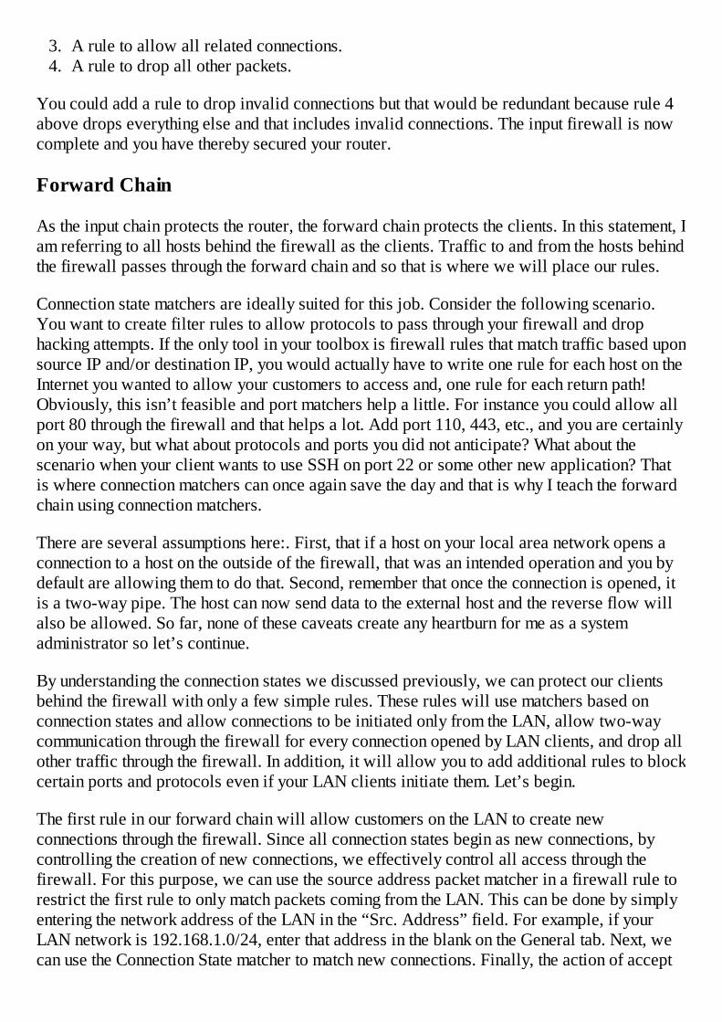
Address Lists
Example – The Basic Firewall
Chapter 9 – NAT, Network Address Translation
Source NAT
Destination NAT
Special Types of NAT Rules
Source NAT With Multiple Public IP Addresses
Destination NAT with Action Redirect
Example – A Simple Masquerade Rule
Example – Destination NAT for a Web Server on the Private Network with PortTranslation
Example – Source NAT to Source Traffic From a Certain IP Address
Example – Destination NAT with the Action Redirect
Service Ports - - NAT Helpers
Connection Tracking (on and off)
Example – Disable Connection Tracking
Tools – Torch
Example – Determining the Source of Traffic on a Network
Chapter 10 - - Bandwidth Limits
Simple Queues
Bursting
Example – Creating a Simple Queue for Computers in an Office Network
Example – Creating a Queue for a Destination Host
Example – Create a Queue for Local Computers with Burst

Packet Mangling
Example – Packet Mangling Using Optimal Mangle
Traffic Prioritization
For Further Study: QOS
Example – Queue Priority for VoIP Traffic
PCQ – Per Connection Queuing
Example – Using PCQ with a Simple Queue, One Limit to All
Chapter 11 – Tools
Bandwidth Test Utility
Example - - Bandwidth Test Utility
Monitoring Tools
Example – Using Torch to Troubleshoot “Slow” Networks
Traffic Graphing
Example – Configure a Graph for all Users in a Subnet
SNMP – Simple Network Management Protocol
Chapter 12 – Local Area Networks
ARP
Example – Create a LAN that Requires Static ARP
DNS
Example – Configure DNS Client and Caching DNS Server
DHCP – Dynamic Host Configuration Protocol
DHCP Client
Example – Add a DHCP Client
DHCP Server
Example – Create a DHCP Server
Example – DHCP Static Leases
Example – DHCP Server Without an IP Pool
HotSpot – Instant Public Internet
Example – Set up HotSpot
Example – Create IP Bindings
Example – Create additional Users
Example – User Profiles
Example – Server Profiles
Example – Walled Garden
Example – Creating a Custom Login Page
Web Proxy
Example – Configuring a Transparent Web Proxy
Example – HTTP Firewall, Allowing or Blocking Certain Sites
Example – Redirect Users to Certain Sites
Example – Logging Web Traffic
Example – Logging to a Remote Syslog Server
Chapter 13 – Storage
System Stores
Example – Explore Stores
Example – Create a Store
Chapter 14 – More RouterOS Tools
Email Tool
Example – Configure the Email Tool
Example – Use a Script With the Email Tool and Scheduler to Create and Send aBackup
Netwatch

Example – Reboot the Router Using Netwatch
Ping
Traceroute
Profile
Chapter 15 – Wireless
Wireless Theory
802.11b
802.11g
802.11n
Channelization – 2.4 GHz 802.11b/g/n
Small Channels
Bridged Versus Routed Access Points and Stations
Routed
Bridged
Configure an Access Point (PtMP) With DHCP Server
Example - - Initial Wireless Interface Configuration
Wireless Security
Controlling Access with MAC Lists
Example – Create an Access List on an AP
Example – Create a Connect List on a Station
Example - - Encryption Using WEP
Example – Encryption Using WPA(2)
Example - - IP Addressing, DNS, Masquerade
Example – Configure a Wireless Interface to be a Routed Station (client)
Example – Create a Virtual AP
Bridging – Point to Point or Point to Multi- -Point
Example – Transparently Bridging a Link
Point to Point Links
Example – Pseudobridge Modes
Wireless Mode Station- -Pseudobridge
Wireless Mode Station- -Pseudobridge- -Clone
Example – Bridge a Station Using Pseudobridge
Supporting Mixed Clients, Routed Stations and Bridged Stations
WDS, Wireless Distribution System
Example – Build a WDS System
NV2- - Nstreme Version Two
Example – Converting an 802.11n PtMP System to NV2
Example – Hiding the SSID
Chapter 16 – Routing
Simple Static Routes
Most Specific Route
Default Routes
Example - - Tying it All Together With Static Routes
Route Distance
Dynamic Routes
Routing Flags
OSPF – A Dynamic Routing Protocol
Link State Protocol
Areas
Configuring OSPF

Example – Add a Static Route
Example – Add a Default Route
Example – Set up OSPF, the Basics
Chapter 17 – VPN Tunnels
General
Point to Point Addressing
PPPoE – Point to Point Protocol over Ethernet, Applying PTP Addressing
Example - - IP Pools
Example - - PPP Profiles
Example – Create a PPPoE Server
Example – Create a User (Secret)
Example – Create a Client Profile
Example – Create a PPPoE Client
PPTP and L2TP Tunnels
Example – Create a PPTP or L2TP Server
Adding Routes for Tunnels
Tunnels With IP Addresses on Same Subnet as LAN Hosts
Configuring L2TP Server
PPP Status Tab
Bridging Tunnels
Example – Create a Bridged EoIP Tunnel
Example – Create a Transparent VPLS Tunnel
Near End of Tunnel (AP)
Far End of Tunnel (station)
Chapter 18 - - Conclusion

References
Appendix 1
Table of Figures
Index


Acknowledgement
An old mentor of mine, a seasoned U.S. Veteran, a former Air Force fighter pilot, and one ofthe “Junction Boys” from Texas A&M University has told me time and time again “for everynegative there is a positive” and our daily mission is to find it. Fortunately, I have learned thatinstead of focusing on the negatives in life, I can appreciate the wisdom that comes from awealth of mistakes, to take daily notice of the unparalleled beauty I see in the world aroundme and most of all to value the relationships I have with those closest to me, my family, myfriends and my co-workers.
Why have I begun with an analysis of positive and negative? Well, I have learned in life thateach of us is blessed by our Creator with many things but one of the most important is thepeople around us, those that touch our lives every day in a large or small way and therebymake it better. Those that live this life with us, the good and the bad, the positive and thenegative, the same daily challenges, joys and disappointments you too experience. In writingthis book I undoubtedly missed some chances to spend time with my wife, to play ball withmy kids, or to have more patience with a co-worker or employee and to each of you that madea sacrifice for me, I say thank you. I know this investment of time did not come without a priceand I can truly appreciate your contribution. Now if I follow Dennis’ mentoring, I must admitthat on the positive side I have learned to appreciate each of you a little more. Again, I saythanks.
Especially to the loves of my life Carolyn, Lauren, Lexie and Drew, thank you for allowingme to do this. I love you all and I am proud you are my family.


INTRODUCTION
You are likely reading this book because you are looking for answers, to questions like “Whatcan this little white plastic box do for me?” or “Why can’t I figure out how to configure thisparticular feature?” Likely you have attempted to read the documentation or a book on thesubject but you still have questions. If that is you, then read on.
I too had these types of questions more than 6 years ago when I downloaded my first trialcopy of RouterOS. It didn’t take long to realize the power I had at my fingertips and quicklylearned to appreciate the numerous features this routing system performs to “wow” my clients.
I have always been a “hands on” type of guy. I learn by doing and I teach through examplesand have attempted to do that in this book but more on that later. If you too want answers andare ready to enhance your “solutions tool box”, then you have picked a winner with MikroTikand RouterOS.
Who or What is MikroTik?
Located in Riga, Latvia, MikroTik was founded in 1995 to develop routers and wireless ISPsystems. Latvia is a member of the European Union and is nestled on the Baltic Sea betweenEstonia and Lithuania. With more than seventy employees at the time of this writing, MikroTikis a growing company with a full-featured router operating system, RouterOS. In 2002,MikroTik entered the hardware manufacturing field with the brand RouterBOARD.RouterBOARD continues to develop new designs, targeting small companies, WISPS(Wireless Internet Service Providers) and wired ISP’s (Internet Service Providers) lookingfor high performance, small footprint and a powerful feature set.
About The Author
Stephen Discher is an entrepreneur and a 1987 graduate of Texas A&M University. He makeshis home in College Station, Texas where he lives with his wife and three children. A nativeof Texas, he has been in the technology field since 1983 when he worked part time as anelectrical technician at a company that built offshore cable handling systems while he wasattending college.
Upon graduation, he started his first company, Deck Systems & Equipment, designing andbuilding custom equipment for the offshore Geophysical industry. In 1999, he sold thecompany and began working as a consultant for numerous companies, all in the technologyfield.
In 1993 he became involved with computers and networking in the telecommunicationsindustry and in 1999 joined as a partner in American Cable Services.
In 2005, he sold his interest in ACS and began working as the Director of Operations forFIBERTOWN, a technology campus and Tier IV data center in Bryan, Texas. Simultaneously,he started Wickson Wireless, a WISP or Wireless Internet Service Provider in Bryan, Texas.During the next few years he earned all of the MikroTik certifications and became a MikroTikCertified Trainer.
In 2010, he left FIBERTOWN to work full time at his WISP, Wickson Wireless and teachingMikroTik classes.
In 2011, he sold Wickson Wireless and today works full time doing MikroTik training withLearnMikroTik.com.
In his spare time, he enjoys flying his 1941 Piper J3 Cub, fly fishing and camping with hisfamily.
What is RouterOS?
In simple terms, RouterOS is routing software that runs on a PC based hardware platform.Whether it’s a conventional X86 based PC, a RouterBOARD, embedded device, or a virtualmachine, RouterOS is an operating system that will make your device a dedicated router, abandwidth shaper, a transparent packet filter, or a wireless enabled device. Have an old PClying around? With RouterOS, it can be converted into a powerful router!
RouterOS can also be installed on a virtual machine, VMware/ESX environment, or parallelsif you are using Mac.
RouterBOARD is a hardware platform manufactured by MikroTik. The product can rangefrom a very small home router to a carrier class access concentrator. If you need features andpower on a budget, then read on. If you are new to MikroTik or RouterOS, this is going toastound you.
RouterBOARD – The MikroTik Hardware Platform
As previously stated, you don’t need a RouterBOARD to run RouterOS; it can be run on anyX86 based personal computer, however, the RouterBOARD platform is a cost efficient seriesof devices specifically designed to be powerful routers. A brief introduction to the productline will help you understand how to pick the correct device for your application.
RouterBOARD Product Designations
RouterBOARDs can be divided into two basic groups: Integrated meaning in a case, ready touse and RouterBOARDs which are bare motherboards ready to accept wireless interfaces anda suitable case.
They are also designated by a product name that is descriptive of the product’s physicalcapabilities.
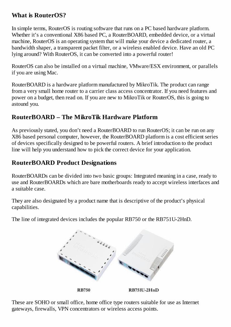
The line of integrated devices includes the popular RB750 or the RB751U-2HnD.
These are SOHO or small office, home office type routers suitable for use as Internetgateways, firewalls, VPN concentrators or wireless access points.

The model number tells you about the capabilities of a RouterBOARD device. For example,the RB designates it is a RouterBOARD, the 7 designates it is a 700 series device withrespect to the base system design, the 5 means 5 Ethernet ports and the 0 in RB750 meansthere is no provision for wireless interfaces, that is, no integrated wireless cards or mini PCIslots to accept a wireless card.
The RB751U-2HnD on the other hand, is a 700 series RouterBOARD with 1 each, 2 GHzwireless interfaces integrated within including dual chain antennas (designated by the letterD), a USB port (designated by the letter U) and capable of high power operation on 802.11n(which includes 802.11b/g operation as well).
At the top of the RouterBOARD line is the RB1100AH, outfitted with 13 Gigabit ports.
This device is suitable for use as an Internet router or firewall in a large office environmentor as the gateway router for an ISP or Internet Service Provider.
If you need more of a custom solution, there is a complete line of RouterBOARDs that willallow you to configure a custom wireless or routing device. These include the 400 seriesdevices as well as the 800 series models and range from small CPE or Customer PremiseEquipment devices that cost less than $50. At the top of the line are the most powerful Gigabitcapable boards with room for up to 4 wireless interfaces such as the RB800.
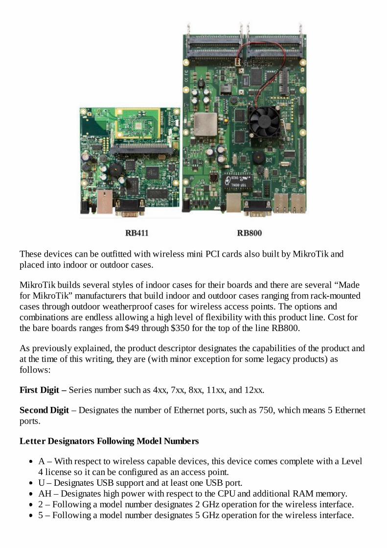
These devices can be outfitted with wireless mini PCI cards also built by MikroTik andplaced into indoor or outdoor cases.
MikroTik builds several styles of indoor cases for their boards and there are several “Madefor MikroTik” manufacturers that build indoor and outdoor cases ranging from rack-mountedcases through outdoor weatherproof cases for wireless access points. The options andcombinations are endless allowing a high level of flexibility with this product line. Cost forthe bare boards ranges from $49 through $350 for the top of the line RB800.
As previously explained, the product descriptor designates the capabilities of the product andat the time of this writing, they are (with minor exception for some legacy products) asfollows:
First Digit – Series number such as 4xx, 7xx, 8xx, 11xx, and 12xx.
Second Digit – Designates the number of Ethernet ports, such as 750, which means 5 Ethernetports.
Letter Designators Following Model Numbers
A – With respect to wireless capable devices, this device comes complete with a Level4 license so it can be configured as an access point.U – Designates USB support and at least one USB port.AH – Designates high power with respect to the CPU and additional RAM memory.2 – Following a model number designates 2 GHz operation for the wireless interface.5 – Following a model number designates 5 GHz operation for the wireless interface.
N - Following a 2 or 5 designates 802.11n capability.H – For wireless devices, designates high RF power output.G – Designates Gigabit capability for the Ethernet ports.L – Designates low cost.D – For wireless devices, designates dual chain 802.11n operation.P – Designates POE or Power over Ethernet output.
As you can see, the product line is extensive with more than 40 boards and interfacesavailable for a wide range of applications. With the availability of integrated, ready to use offthe shelf routers or components to allow you to custom build a device to your specifications,the RouterBOARD product line is both versatile and powerful.
About This Book
I have written this book as a text for my MTCNA or MikroTik Certified Network Associatetraining classes, which I conduct throughout the United States and abroad. Titled “RouterOSby Example”, I have taken the approach that simply describing features is pointless.
This book is not a manual for the operating system and so it does not describe every feature indetail. If you are looking for a feature reference book, MikroTik offers the manual online andfree of charge. That material will not be duplicated in this book.
Users need to understand the basic features and associated concepts but without practicalexamples, they are left unequipped to solve the issues they set out to solve with this greatproduct. I want to give you applications, examples, and recommended practices, and onlydescribe the features you typically need and use. The lesser used features and settings are inthe manual, and again it is free.
This book is meant to teach the basics using the subjects in the MTCNA syllabus written byMikroTik. They believe, as well as I do, that the MTCNA program contains all of the featuresyou will need to become proficient at a beginner or intermediate level and my goal in thisbook is to deliver all of that information to you according to the current syllabus on the date ofthis writing. I have followed the order of the syllabus as much as possible, but reorderedsome topics to present them in a more logical progression. I have strived to cover everysingle topic in the MTCNA syllabus in sufficient detail with examples.
Since the MTCNA is the first certification and considered the basic or foundationcertification, I will not cover every single feature or detail available in RouterOS, yet youshould receive enough knowledge to use the system in powerful ways and through experiencebecome quite proficient with the most complex setups.
Each bolded section is based on a concept and titled according to the feature that provides theconcept. Most sections contain real life applications presented through examples.
The Table of Contents will lead you to both concepts and examples and I have included anIndex of Terms in the back of the book. I approach indexes a little differently than someauthors. I do not index every occurrence of a word. Instead, I index words based on the pagein the book where the concept is best explained. Also included in the book is a Table of

Figures. Screen shots are not included in that table because they are so numerous.
Ready to solve problems and reduce your workload? Then read on!


Chapter 1 - First Time Access
Whether you are installing RouterOS on a non-RouterBOARD device or accessing aRouterBOARD with RouterOS already installed, the basic method of access is the same.There are several options to access the operating system and they are WinBox (the GUI,graphical user interface), Webfig (via HTTP and your web browser), and command line viaserial, telnet or SSH. Additionally, the RouterOS API provides yet another manner ofaccessing the device that is far beyond the scope of this book.
WinBox
WinBox is a Microsoft Windows based GUI that is by far the simplest way to configure aRouterOS device. It is extremely powerful and allows configuration of 99% of the feature set.WinBox is a standalone executable, meaning it isn’t necessary to install anything on your PCother than to download the program, simply save it to your computer and double click it tostart it. If you don’t have WinBox already you can download it from MikroTik.com.
The first time you try to connect to your MikroTik device it may or may not have an IP addressconfigured on it. One of the great features of WinBox is the ability to “get in” without anactual IP address but a note of caution here is needed. Access using the MAC address shouldonly be used in order to configure an IP address on the device. It is not a reliable way ofaccessing the router. I hesitate to call it an unreliable method, but it’s not the correct methodand sometimes you may get unexpected results, i.e., configuration pages that don’t properlypopulate or frequent disconnections. The feature is meant to be used it in an emergency or forfirst time access to configure an IP address on it and then to go back in using the IP.
With WinBox running, simply click the square button with the three dots to scan the local areanetwork for MikroTik devices.
Then, if you click on the MAC address of your device, it will be loaded into the “connect to”line. Conversely, if you click the IP address it will load the IP address into the same line.Clicking the “Connect” button will then connect to the router.
Navigating WinBox
Navigating WinBox is straightforward. On the left side of the screen are “buttons” andclicking them either expands the menu selection provided by the button or it opens a
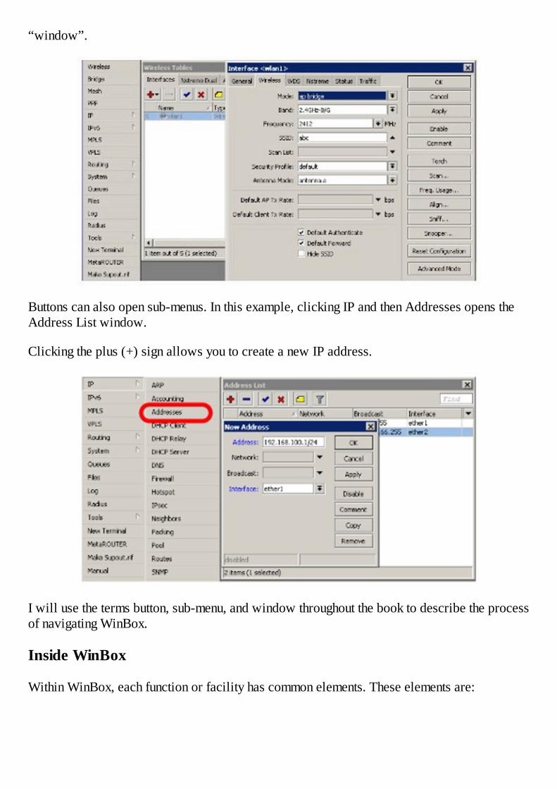
“window”.
Buttons can also open sub-menus. In this example, clicking IP and then Addresses opens theAddress List window.
Clicking the plus (+) sign allows you to create a new IP address.
I will use the terms button, sub-menu, and window throughout the book to describe the processof navigating WinBox.
Inside WinBox
Within WinBox, each function or facility has common elements. These elements are:
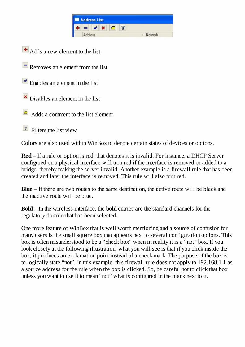
Adds a new element to the list
Removes an element from the list
Enables an element in the list
Disables an element in the list
Adds a comment to the list element
Filters the list view
Colors are also used within WinBox to denote certain states of devices or options.
Red – If a rule or option is red, that denotes it is invalid. For instance, a DHCP Serverconfigured on a physical interface will turn red if the interface is removed or added to abridge, thereby making the server invalid. Another example is a firewall rule that has beencreated and later the interface is removed. This rule will also turn red.
Blue – If there are two routes to the same destination, the active route will be black andthe inactive route will be blue.
Bold – In the wireless interface, the bold entries are the standard channels for theregulatory domain that has been selected.
One more feature of WinBox that is well worth mentioning and a source of confusion formany users is the small square box that appears next to several configuration options. Thisbox is often misunderstood to be a “check box” when in reality it is a “not” box. If youlook closely at the following illustration, what you will see is that if you click inside thebox, it produces an exclamation point instead of a check mark. The purpose of the box isto logically state “not”. In this example, this firewall rule does not apply to 192.168.1.1 asa source address for the rule when the box is clicked. So, be careful not to click that boxunless you want to use it to mean “not” what is configured in the blank next to it.

Safe Mode
In class I always say “safe mode is your friend”, but what is safe mode? Safe mode is a modewhere configuration changes are reversible. By this I mean that typically when you apply achange or click OK, the change is immediate and is saved so when the router is rebooted, theconfiguration is still there.
In safe mode, if you lose your connection to the router, all changes made after entering safemode are reversed as if they never happened. I recommend using safe mode when firstlearning RouterOS, however, you must exit safe mode for your changes to be saved. Theprocess is: enter safe mode, make changes, if everything looks ok, exit safe mode. You canthen enter it again, make more changes, and so on.
Example – Entering Safe Mode
Safe mode can be entered inside WinBox in version 5 and later or from the command line.
From WinBox, click the button Safe Mode:
Alternative, from the command line, type the key combination ctrl-x. The prompt will changeas follows:
To exit safe mode, click the button to un-toggle it or type ctrl-x again.
If you are in safe mode and do not want your changes saved or to lose your ability to accessthe router, simply click the X to exit WinBox. If you are in a terminal window and still have
connectivity to the router, type ctrl-d to exit safe mode and roll back changes.
Command Line Terminal Options
This section is included at this point in the book to keep in concert with the official MikroTikMTCNA course syllabus, however, these concepts are more advanced and you may wish toskip to page 37 and come back here when you are more comfortable with RouterOS or need itas a reference.
Telnet and SSH
Once the device has an IP address configured, telnet and SSH may be used to access thedevice. Once you are logged into the device, the command line commands parallel theWinBox command sequence for almost every function. In version 5.X there are still a fewremaining functions that do not follow the command sequence displayed in WinBox. You willlearn these exceptions as you become familiar with the command line.
Serial Terminal
Using a serial cable is the “back door” method to get into the router if all else fails. Forexample, if you accidentally disabled all of your Ethernet ports you will no longer be able toget in through WinBox, telnet or SSH, so serial is your last option.
If your computer does not have a serial port, you will need to purchase a USB to Serialadapter at any computer store and install the drivers to use serial terminal.
Example- Forgotten Password
If you have forgotten the user name or password (note that there is no password recoveryroutine), you will need to re-flash the board using NetInstall. Please understand, you will loseyour configuration but there is no other way to regain access to the device. There is nopassword recovery procedure.
Caution: NetInstall will destroy all configuration on the device if you do not check “keep oldconfiguration” and in some cases, depending on the age of the device and the version you arerunning, may destroy the configuration even if you do check that option. Always make backupsand document your passwords whenever possible.
The NetInstall process is accomplished as follows:
Download the NetInstall zip file from www.mikrotik.com and unzip it on your desktop.
Download the RouterOS file (the .npk package) from www.mikrotik.com and save ondesktop.
Start your favorite serial terminal program (Hyperterm or Putty work fine).

These settings work with Putty for accessing a RouterBOARD. Putty will be used forpurposes of this example. Putty.exe is a freely downloadable SSH/serial terminal client:
Set a static IP on your PC’s Ethernet adapter, for example 192.168.1.1 with a netmask of255.255.255.0.
Start NetInstall on the PC. You should see a window like this:
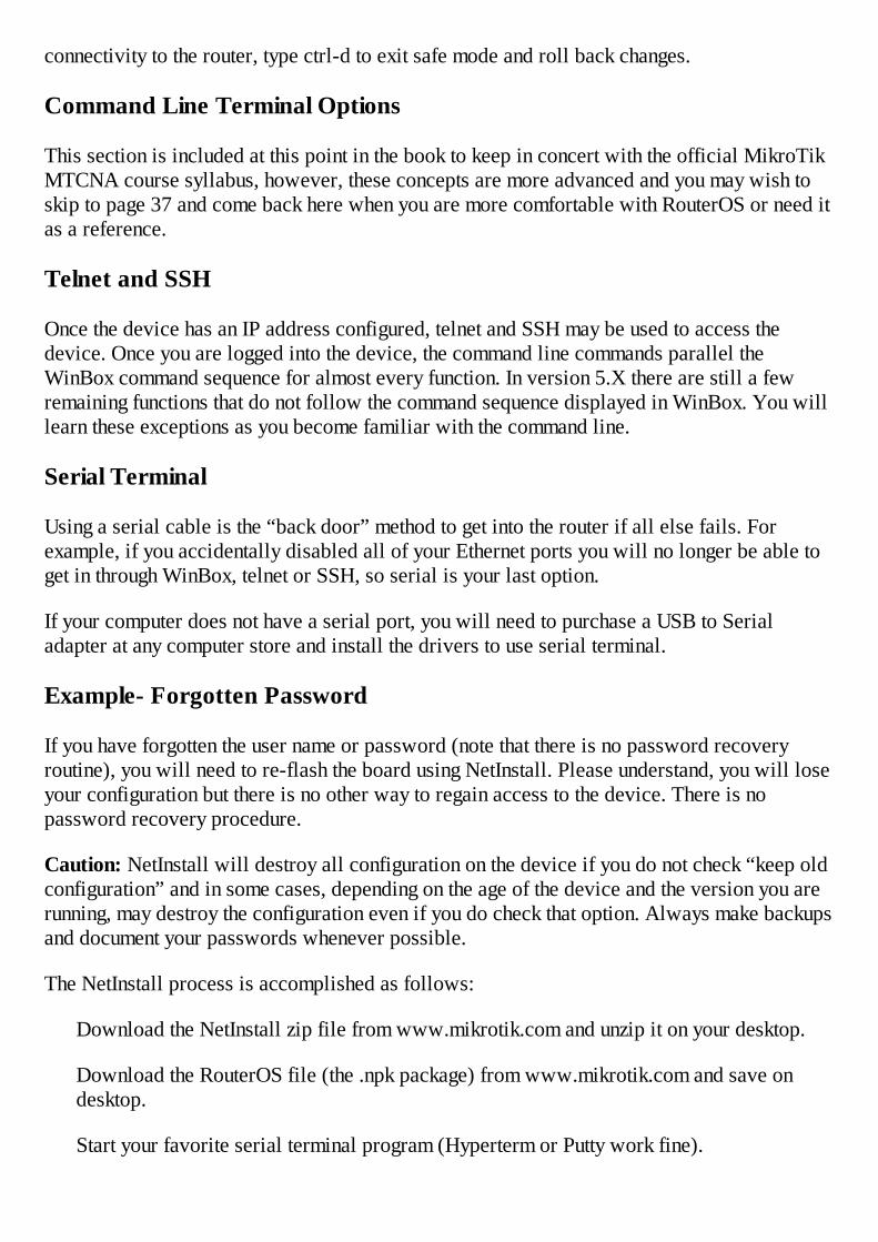
Click the Net Booting button and configure an IP address to give the board to be flashedon the same subnet as your PC. In this example, use 192.168.1.2 and check the box:
Click OK. Next, power up the board and watch the terminal on Putty. When the screensays “Press any key within 2 seconds to enter setup.” press the enter key. Next type theletter “o” then “1” and then “x”. Case of the commands is important.
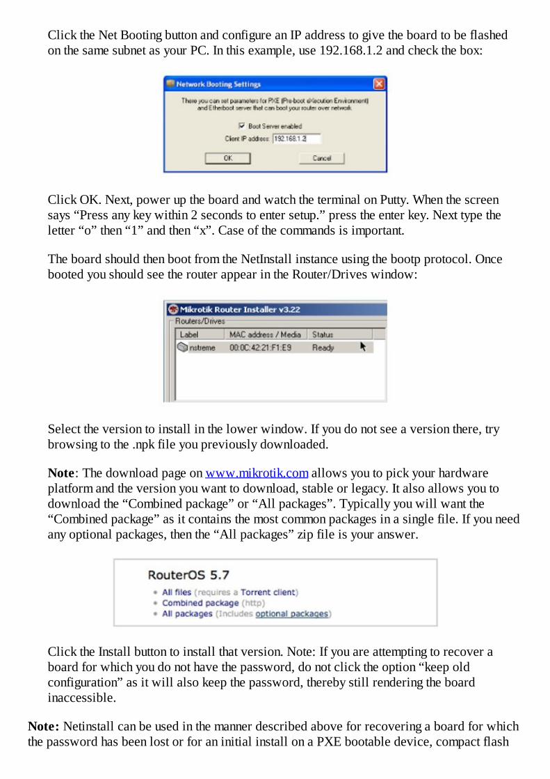
The board should then boot from the NetInstall instance using the bootp protocol. Oncebooted you should see the router appear in the Router/Drives window:
Select the version to install in the lower window. If you do not see a version there, trybrowsing to the .npk file you previously downloaded.
Note: The download page on www.mikrotik.com allows you to pick your hardwareplatform and the version you want to download, stable or legacy. It also allows you todownload the “Combined package” or “All packages”. Typically you will want the“Combined package” as it contains the most common packages in a single file. If you needany optional packages, then the “All packages” zip file is your answer.
Click the Install button to install that version. Note: If you are attempting to recover aboard for which you do not have the password, do not click the option “keep oldconfiguration” as it will also keep the password, thereby still rendering the boardinaccessible.
Note: Netinstall can be used in the manner described above for recovering a board for whichthe password has been lost or for an initial install on a PXE bootable device, compact flash

drive, hard drive, etc.
Creating the Basic Configuration
Due to the power of this device, even a basic configuration can be daunting. I will walk youthrough the creation of a basic configuration that will allow you to access this device easilyuntil you are more experienced at configuring it. I will not explain the steps here, and insteadwill explain them in depth later in the book.
When you first power up the device and connect to it using WinBox as described on page 27,provided the device has not been configured, you will see a window like this:
I recommend you remove the default configuration, and this will allow you to create your ownwithout anything cluttering things up.
Note that you should be accessing the router via the MAC address as previously explainedwith WinBox. If you are in through the default IP address of 192.168.88.1, you were likelyjust disconnected when you removed the default configuration so you will need to relaunchWinBox and enter through the MAC address.
At this point you will want to add an IP address or two, DHCP Server and a few otherconfigurations. To assist you, I have developed a script you can simply paste into the routerand it will configure everything for you and get you started on the right track. You maydownload the script fromhttp://learnmikrotik.com/book/basicconfig/config.txt. The script is a text file so copy it to yourclipboard and then in WinBox, click the New Terminal button and inside the terminal windowright click with your mouse and select paste and watch the script configure the necessities.

At this point you should have a router with ether1 ready to connect to the Internet providerwith the following assumptions:
Ether1 is the WAN port; it will expect DHCP from the provider.
Ether2 is the LAN port; it will give your computer a DHCP address.
If you have a wireless card, it will broadcast 2.4 GHz with the wireless network IDMikroTik. It will also pass out DHCP addresses.
You can connect with a cable to ether2 or wirelessly.
The system clock will be synchronized to NIST, the National Institute of Standards andTechnology and the clock will be set to US Central time.
The router will provide basic Internet access, has no admin password, no encryption andno firewall so please understand
there is no security provided! If you do not have Internet access and enjoy typing, you cantype the commands on the following page into a terminal window instead of pasting.
/ip address
add address=192.168.1.1/24 disabled=no interface=ether2
add address=192.168.2.1/24 disabled=no interface=wlan1
/ip pool
add name=dhcp_pool1 ranges=192.168.1.2-192.168.1.254
add name=dhcp_pool2 ranges=192.168.2.2-192.168.2.254
/ip dhcp-server

add address-pool=dhcp_pool1 \
disabled=no interface=ether2 lease-time=3d name=dhcp1
add address-pool=dhcp_pool2 \
disabled=no interface=wlan1 lease-time=3d name=dhcp2
/ip dhcp-server config
set store-leases-disk=5m
/ip dhcp-server network
add address=192.168.1.0/24 dns-server=4.2.2.2 gateway=192.168.1.1
add address=192.168.2.0/24 dns-server=4.2.2.2 gateway=192.168.2.1
/system ntp client
set enabled=yes mode=unicast primary-ntp=50.19.122.125
/interface wireless
set 0 band=2ghz-b default-authentication=yes disabled=no\
wireless-protocol=802.11 mode=ap-bridge
/ip dhcp-client
add interface=ether1 disabled=no
/ip firewall nat
This basic configuration will get you started learning RouterOS.
Interfaces
Interfaces are the physical ports that allow input and output connections to the router.Interfaces are accessed from the Interfaces button. Interfaces can be renamed by doubleclicking on the interface name in the Interfaces list window and then setting their Name on theGeneral tab. This will help you identify them physically or logically or assist you withtroubleshooting.
I suggest using comments on interfaces rather than renaming them. My reason is that mostenclosures are labeled with the same interface name as it appears in RouterOS and keepingthem the same makes things simpler.
Example – Add an IP Address

The first step in learning to configure this device is to gain access and configure an IPaddress. The assumption is made that you understand basic networking and subnetting andaccept the fact that for two hosts to communicate on the same local area network or LAN, theymust be on the same subnet or they will require the help of a router that has addresses on bothsubnets.
That being said, to add an IP address to a RouterOS device, it is first necessary to gain accessthrough one of the methods previous described including WinBox through the MAC address,or through the serial terminal as outlined beginning on page 27. If WinBox does not see yourrouter, try a different interface or use the serial terminal method.
1. Begin by clicking the IP button and then Addresses. Click the plus sign to add a newIP address to the desired interface.
Note that RouterOS uses CIDR or Classless Inter-Domain Routing or slash notation todetermine the subnet and this must be included on the address line. The format for CIDRnotation is 192.168.1.1/24 where the /24 determines the subnet.
2. Click ok to save the address.


Chapter 2 – User Management
The title of this chapter is User Management, which should not be confused withUserManager. UserManager is a totally separate package distributed by MikroTik and isbasically their implementation of Radius server. User Management is a function withinRouterOS and should therefore not be confused with the UserManager optional package.
Users can be created with three different permission levels. By default, there exists a usernamed admin with permissions of full. By default the admin password is blank. Obviously forsecurity purposes, changing the admin password to something a bit harder to guess than ablank password is prudent, however, you may wish to create several users with variouslevels of access.
Note: This task can be centralized and the administrative effort of controlling user access canbe simplified by using a central authentication mechanism such as Radius or MikroTik’sUserManager. More on that on page 45.
In WinBox, users are created by clicking the System button and then the Users menu item. Theplus sign will add a user and allow you to set the password. Also selectable is the group andthere are three by default. The group “full” has full read and write access to the router while“read” can only view the configuration and “write” can read and write the configuration.These three default example groups provide some demonstration of the granularity with therights you can give each of them. Don’t be confused by the group named “write”. The writegroup isn’t substantially different by design, it just has a different set of permissions ascreated by default. Typically, I recommend you create users with read access for anyone thatdoesn’t need to change the configuration and full access for your trusted admins. Anydeviation on this policy should be made on a case-by-case basis.
From the System Button, select Users.
From the Groups tab, you can double click a group to see their details.

As you can see, there are a lot of possible combinations of group permissions available:
Your selections are dependent upon your individual circumstances.
Example - User and Group Assignments and Policy
User creation and group assignment is really simple and self-explanatory so instead of anexample, a best practice might be more meaningful and useful.
Here is an example of groups and access rights. You are considering using a consultant toprovide network evaluation and possible configuration but don’t want him or her to accidentlycause an outage in your production network. Before giving anyone the “keys to the kingdom” Irecommend creating for him or her a user with read access. This way, they are able to viewyour entire configuration without actually being able to make changes. Once you arecomfortable with their abilities, then you can change their group to full.
For Further Study – UserManager
If you aren’t ready to explore an advanced topic, you may skip this section and return to itlater.
Imagine you are a network administrator with various levels of technicians and admins. Youwant a centralized approach to user management and various levels of access to ensure yourability to terminate network access for an employee quickly. The best and most scalablesolution to this situation is MikroTik’s UserManager.
The installation of UserManager goes beyond the scope of this book and the MTCNAcertification but a few instructions here can help steer you in the right direction. First,
UserManager should be installed on a machine that is in a very stable part of your networkwith reliable power and connectivity so I suggest your NOC or data center as the ideallocation. Since it is available as a package for RouterOS, it can be installed on a physicalrouter or a virtual machine running the X86 version of RouterOS, the latter being my firstchoice. Typically I put my Dude server and my UserManager on the same virtual machinesince I run VMware in my data center. (The Dude is MikroTik’s network monitoring programand is available for download at no charge on MikroTik’s web site.) UserManager creates alarge quantity of log files and the availability of the extra disk space a virtual machine canprovide is helpful.
Once UserManager is installed and working, you will install a radius client on each router toauthenticate from UserManager. Next you will check the box for “Use Radius” under theUser’s List through the AAA button. I recommend setting the local admin password on therouter to something difficult to guess and only known to you or a trusted employee. This localuser is always available to log into the device even if the UserManager server is unavailable.Then create users within UserManager for each of your technicians with the appropriate UserGroup. If a technician is terminated, you simply remove their account in UserManager todisable their access to the entire network.
Obviously there are many steps in-between the portions I have described and the MikroTikWiki is a great place to go for a step-by-step process to deploy UserManager. Hopefully thepieces I have added here will fill in the remainder of the blanks and ensure a successfulsolution for centralized user management.

Chapter 3 – Upgrading andDowngrading the Operating System,Package Management
RouterBOARDs come from MikroTik preloaded with RouterOS. MikroTik recommends thatyou upgrade your board to the latest version of RouterOS before beginning any configuration.
The operating system is in constant development and new features or bug fixes are frequentlyavailable, sometimes even monthly. The decision to do an upgrade on a production system onthe other hand should be based on some basic logical reasoning such as:
1. Is there a feature I want to add to my device that the new OS will provide?
2. Is there a security vulnerability this version solves?
3. Is there a bug fix this version provides?
4. Do I need to upgrade to provide support for some new hardware?
All of these are valid reasons to upgrade your device. As a friend of mine says, “Everyproblem is the result of a previous solution.” and I think that holds true for upgrades. Anotherone I am sure you have heard is “if it isn't broken don’t fix it”. I think you get the point here, ifthe criteria expressed above doesn’t apply, leave your router alone. It is doing its job anddoesn’t need your help, however, if you need to do an upgrade, read on.
Example – Upgrading the Operating System
1. First, you must download the upgrade package from MikroTik. After web browsingto the MikroTik site, locate the download section and select the platform you want toupgrade. See page 36 if you have any questions about which file to download.
2. Download the .npk package to your desktop. Typically the package you want is thestable version, “combined package”. This single file contains the same features that areinstalled by default on the device.
3. Once the package is downloaded (typically around 12 megs), launch WinBox andaccess through the device’s IP address, not through the MAC address. As stated before,the Layer 3 method is the best for all normal router management.
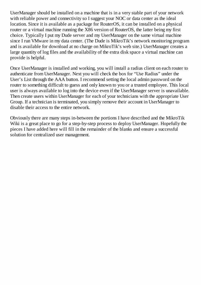
4. Inside WinBox, click the Files button. This will open the Files List showing all thevisible files stored on the router.
5. Next, drag the package from your desktop to the files window. This can be a bittedious, depending on how the files are sorted in the files window. Dropping the fileinside a folder will prevent the upgrade from taking place so use care to get it at the topof the list. One trick here is to click the Backup button in the Files List. This willproduce and save a backup file, which sorts to the top of the list and allows you a littlespace in which to drop the upgrade package. The npk file doesn’t have to be the top filein the list, but make sure it isn’t in a folder.
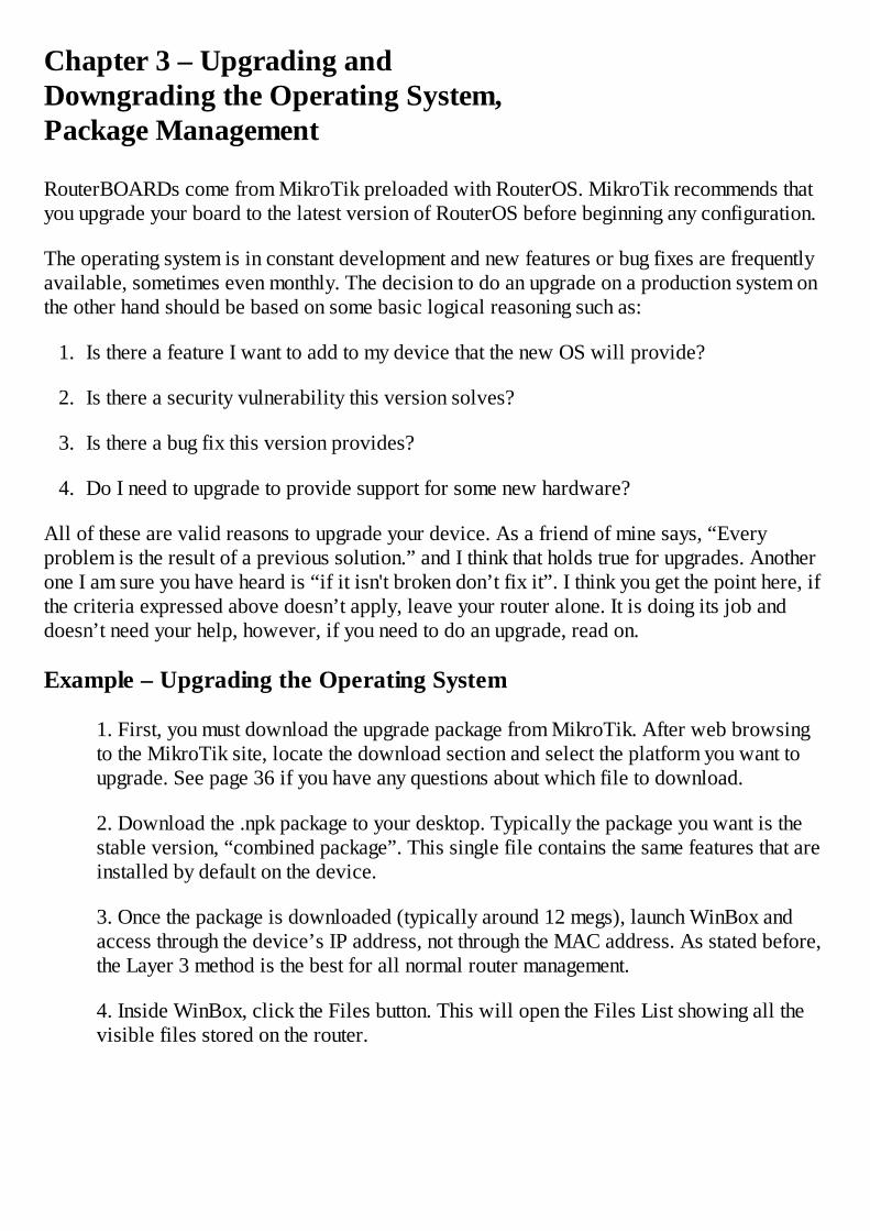
6. Dropping the file in the area identified by the red arrow will produce the desiredresult:
7. Once the file has completely uploaded, issue a reboot command by clicking Systemand Reboot.
Note: Pulling the power at this point will not upgrade the router; you must enter agraceful reboot using the reboot command due to the process RouterOS uses to updatethe device.
After a few minutes, your router will return to operation with the new version installed.
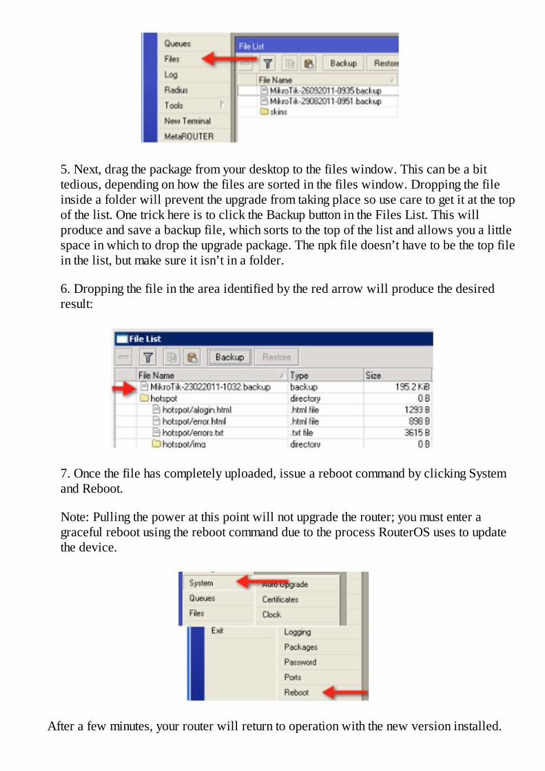
You can confirm in several places, including WinBox and in the System Packages List.
Confirm in WinBox:
And in the Package List:
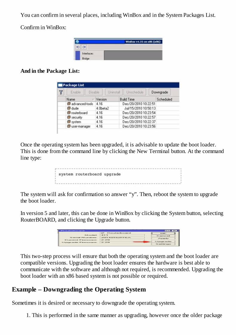
Once the operating system has been upgraded, it is advisable to update the boot loader.This is done from the command line by clicking the New Terminal button. At the commandline type:
The system will ask for confirmation so answer “y”. Then, reboot the system to upgradethe boot loader.
In version 5 and later, this can be done in WinBox by clicking the System button, selectingRouterBOARD, and clicking the Upgrade button.
This two-step process will ensure that both the operating system and the boot loader arecompatible versions. Upgrading the boot loader ensures the hardware is best able tocommunicate with the software and although not required, is recommended. Upgrading theboot loader with an x86 based system is not possible or required.
Example – Downgrading the Operating System
Sometimes it is desired or necessary to downgrade the operating system.
1. This is performed in the same manner as upgrading, however once the older package

has been copied into the Files List, click the System button and select the Packagesmenu item.
2. In the Packages List, select all of the packages and click the Downgrade button.
3. Reboot the router and the operating system will be downgraded.
Note: I do not recommend running different versions of packages unless you know whatyou are doing. To do so may be possible but can produce unwanted results.
Example – Upgrading using FTP
If WinBox and the simple drag and drop method is not possible, you can use an FTP client totransfer the package to the router and then issue a reboot command.
Example – Adding a Package
Sometimes you find it necessary to add a package not already installed on the router. This maybe true for adding a feature like UserManager or if you accidently uninstalled a package thatyou now need. Packages not included in the combined package may be downloaded as a zipfile from the same page on the MikroTik site where you downloaded the upgrade package.
To install a single package:
1. Download the “all packages” and unzip on your desktop.
2. Drag the package to your Files List as you did previously for the system upgrade.
3. Reboot the router and the new package will be installed.
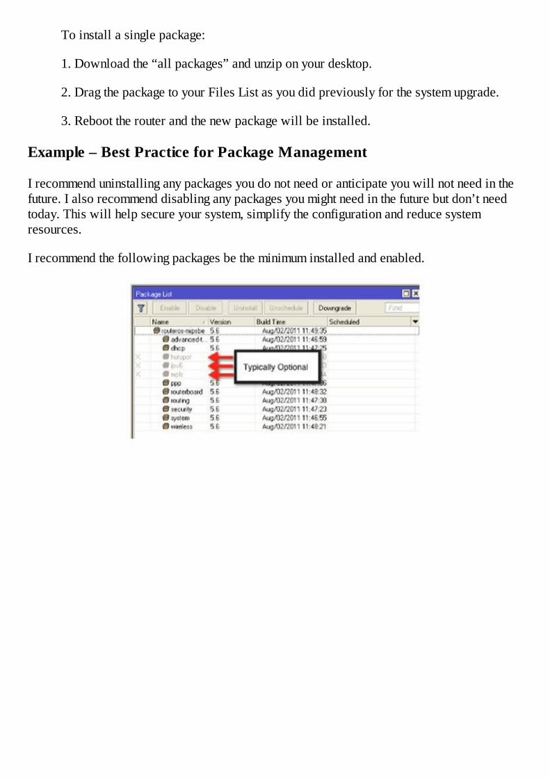
Example – Best Practice for Package Management
I recommend uninstalling any packages you do not need or anticipate you will not need in thefuture. I also recommend disabling any packages you might need in the future but don’t needtoday. This will help secure your system, simplify the configuration and reduce systemresources.
I recommend the following packages be the minimum installed and enabled.


Chapter 4 – Router Identity
The identity of the router you are logged into is shown in several places in RouterOS. Bydefault, the identity is MikroTik, which is obviously not very useful in your network so it is agood idea to make setting the router identity part of your standard configuration routine. Theconvention you choose is entirely up to you, but I have found that using the physical address ofthe client is often helpful to help troubleshoot at a later time. For example, setting the RouterIdentity to “103 Smith Street” is a good practice.
The router identity is found in several places. In WinBox it appears on the title bar:
In the terminal window at the prompt:
And, in the IP Neighbors List:
Example – Setting the System Identity
The system identity is set using the commands System and Identity:


Chapter 5 – System Time and the NTP Protocol
NTP Client Setup
Having the system time set accurately is important for many purposes, especially logging andtroubleshooting. Since RouterBOARDs do not have an onboard battery to keep the clockrunning, setting up the NTP client should be a part of your standard configuration.
The function of the NTP client is to query an NTP server and get the current time and then setthe local clock. The actual displayed time on the RouterBOARD system will be dependent onthe local time setting on the device.
Example – Setting Up the NTP Client
The NTP client is part of the default packages so there is no package that needs to be added,simply select System and NTP Client. To have the device query a public Internet time server,set the NTP Client to Enabled, select the Mode as “unicast” and set the Primary NTP Serverto a DNS resolvable name or IP address. I suggest “us.pool.ntp.org” for U.S. based systems.Adding a secondary NTP server is optional and you can consider one like time.windows.com.
Using us.pool.ntp.org and simply pool.ntp.org will typically yield two different NTP servers.Once the router is connected to the Internet, the DNS server will resolve the DNS name andthen these NTP servers will be queried for the current date and time.
System Clock
Setting up the NTP client will not ensure the local clock is accurate for local time so you mustset your time zone on the Clock setting to ensure your clock information is meaningful.
Example – Setting the System Clock Manually and Setting the Time Zone
1. Manually setting the clock is not recommended because every time the routerreboots, the time and date settings are lost. The system clock is set under System andClock:

2. It is only necessary to select your local time zone from the pull-down list. The DSTActive checkbox is a read-only indication of whether the standard settings dictate thecurrent existence of daylight savings time. It is only configurable on the Manual TimeZone tab by setting the beginning and ending dates for daylight savings time.
Advanced NTP Server Setup
This process is not needed for a basic setup. If you do not want to use an Internet based timeserver, or if you simply want to run your own, that is possible by adding the NTP Serveroptional package found in the package NTP. See Chapter 3 for instructions on PackageManagement.
Once the NTP package has been added and the router rebooted, the NTP server can beconfigured.
Example – Enabling NTP Server
1. Download the “optional packages” zip file from mikrotik.com.
2. Unzip the package on your desktop.
3. Drag the NTP package into the files window.
4. Reboot the router. Once the router reboots, click the System button and then NTPServer and enable the NTP server for the protocol of your choice(s). Typicallychecking “enabled” is the only setting required.
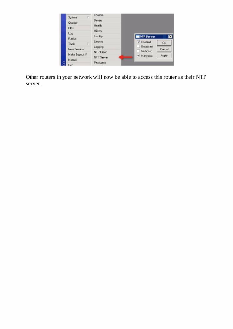
Other routers in your network will now be able to access this router as their NTPserver.

Chapter 6 – Backups
I once saw a sign that read, “Blessed is the pessimist for he hath made backups". I could nothave said it better myself, as nothing is more difficult than trying to remember a configurationwhile screaming customers are down. Luckily, creating backups in RouterOS is quite easilydone and can be automated as well to provide a high level of disaster recovery preparedness.
In summary, there are two types of backups – binary and text based. A binary backup is noteditable, but is simple to produce and easy to restore. A text-based backup on the other handis editable and can be restored to different hardware platforms by doing some simple editingwith your favorite text editor such as Windows Notepad.
So, with two possible backup types, which do you choose? Well, my simple response to thatis both. Each has its own unique value and by producing both you have more flexibility whendisaster strikes or if you simply need to upgrade a device.
A binary backup is typically simple to restore to a new device if it is exactly the same makeand model. For instance, if you are replacing a RouterBOARD 433 board with a newRouterBOARD 433, a binary backup can be restored in seconds with typically one hundredpercent accuracy. By accuracy, I mean that every interface will be configured exactly the sameas before thereby producing a clone of the original device configuration. That being said,when changing platforms, the result might not be as seamless. For instance, if you restore abackup made on a RouterBOARD 450 to a RouterBOARD 433, the most obvious problem isa difference in the number of interfaces. In this case, the text-based backup makes perfectsense.
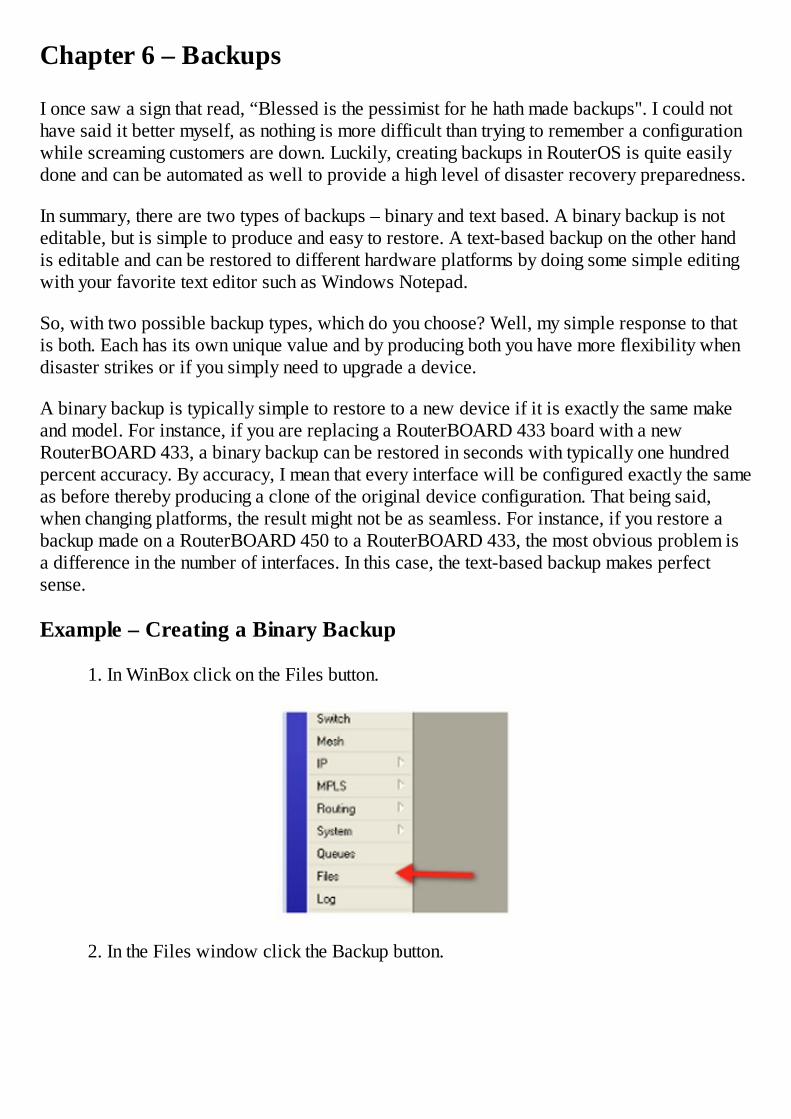
Example – Creating a Binary Backup
1. In WinBox click on the Files button.
2. In the Files window click the Backup button.
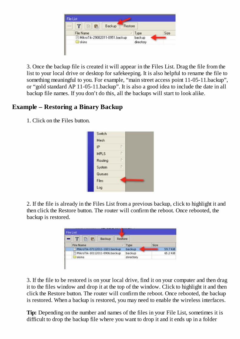
3. Once the backup file is created it will appear in the Files List. Drag the file from thelist to your local drive or desktop for safekeeping. It is also helpful to rename the file tosomething meaningful to you. For example, “main street access point 11-05-11.backup”,or “gold standard AP 11-05-11.backup”. It is also a good idea to include the date in allbackup file names. If you don’t do this, all the backups will start to look alike.
Example – Restoring a Binary Backup
1. Click on the Files button.
2. If the file is already in the Files List from a previous backup, click to highlight it andthen click the Restore button. The router will confirm the reboot. Once rebooted, thebackup is restored.
3. If the file to be restored is on your local drive, find it on your computer and then dragit to the files window and drop it at the top of the window. Click to highlight it and thenclick the Restore button. The router will confirm the reboot. Once rebooted, the backupis restored. When a backup is restored, you may need to enable the wireless interfaces.
Tip: Depending on the number and names of the files in your File List, sometimes it isdifficult to drop the backup file where you want to drop it and it ends up in a folder

rather than the root directory. A good way to fix this is to create another backup usingthe process above which will put the fresh backup at the top of your files list andthereby create some space above any folders. Then, simply drag and drop in the newfile and this operation is made much easier.
Text Based Backups
My recommendation when restoring a text backup or “export” is to spend some time in yourtext editor cleaning up the configuration before importing it on the new hardware. Inparticular, do a word search for the phrase “MAC Address=”. I recommend removing all ofthose configuration segments, thereby making the restoration more universal. If you don’t,when the import occurs, those lines will not be imported because the MAC address will notmatch the original hardware. Simply removing those configuration variables causes the file toload properly and typically without error.
Another use for the text backup is to establish a “gold standard” configuration. A goldstandard is a configuration that is used on all of your devices with general configurationoptions such as NTP client, clock settings, and SNMP (Simple Network ManagementProtocol) community strings, to name a few. By configuring a single device with all of thestandard options you normally want, you can then product a text export and edit it using a texteditor, copying and pasting the appropriate sections into a new text file. Once you have all ofyour configuration sections, test them on a new device and this file becomes your goldstandard.
Example – Creating a Text Export (text backup)
The text export is created from the command line only.
1. Open a terminal window by clicking the New Terminal button.
2. At the root prompt, type export file=[your file name here]. Of course, the squarebrackets are not actually typed, you should be naming your file in that field.
Example: export file=myconfig. It is not necessary to specify the file extension, it will beadded automatically.
Producing the export will take 100% CPU for a few seconds but will then produce a filein the Files List. From there you can drag and drop it to your desktop for renaming andfurther editing.

You can also omit the “files=” portion of the command and it will export the configurationto the terminal window. From there you can copy and paste parts of the file for useelsewhere.
Also note that the export is produced relative to the portion of the command tree you arein. For example, from the root of the command tree, you will export the entireconfiguration. By typing IP Address and enter, you will then be inside the IP Addressmenu branch and an export from there will only produce that portion of your configuration.
Example – Importing a Text Backup
There are several methods of using the text backup you have created and edited. One way is tocopy the text to your clipboard and then right click inside a New Terminal window and selectpaste. This way the commands are executed “real time” so you can watch the effects as theyoccur. Another method is to import the file from the command line.
1. In WinBox, click the New Terminal button to open a terminal window.
2. Drag the file to be imported into the File List root directory.
3. At the command line type import file=FileName.rsc.
A shortcut here is to type the command less the file name and then hit the tab key todisplay all importable files. Typing a portion of the file name and hitting the tab key again

will complete the name for you.


Chapter 7 – Licensing
One of the attributes of RouterOS that delivers the most value is the base feature set, which isconsistent across the entire license range. While many manufacturers require additional feesto add even standard base features, MikroTik delivers all of the features in all license levelsand simply restricts the number of instances. Licenses are included with RouterBOARDs andlicensing is typically not an area where you will need to spend much time for basic setups.However, if you need to install RouterOS on a PC or turn a RouterBOARD designed as aclient device into an access point, then this information is important.
For example, with a level 3 license, you can construct a point-to-point link with a single clientbut to add multiple clients in ap-bridge mode, a level 4 license is required. On the other hand,MPLS, an advanced feature, is available across the entire license level spectrum.
The following chart displays the various license levels and their associated features:


Some additional things to know about licenses are that they never expire, level 4 and higherlicenses include email support for up to 15 days after purchase, can support an unlimitednumber of interfaces, and they can only be used for one installation.
All RouterBOARDs come complete with a license installed, the level of which is determinedby the board’s purpose. For example, if the board is intended to be a CPE (customer premiseequipment) device, it comes with a level 3 license. Access point or AP boards come with atleast a level 4 license and so on.
Licenses cannot be upgraded but they can be purchased and replaced. For example, if youown a device with a level 3 license, you can purchase a level 4 license and install it on thedevice thereby turning it into an access point. Changing license levels is considered theequivalent of installing a new license, not an upgrade, so you will have to pay the full cost ofthe level 4 license and not just an upgrade charge.
Licenses can be bought by creating an account at mikrotik.com and entering the software ID asdetailed in the examples that follow.
Example – Determining Your License Level
To determine the level of license installed on your device, click on the System button and then

License.
Example – Install a License
1. To obtain a license key, repeat the procedure in the previous example and copy theSoftware ID to your clipboard. Create an account and log in at Mikrotik.com. Purchasea new key using the Software ID and obtain the new key.
The key will look like this:
You can copy the key to your clipboard for installation. You should copy all of the text asfollows including “-----BEGIN MIKROTIK SOFTWARE KEY: ------------“ and “-----END MIKROTIK SOFTWARE KEY--------------“. To paste the key into the router, selectSystem License and click the Paste Key button.
2. An alternate method is to use the .key file generated by MikroTik. Click the ImportKey button and browse to the .key file to install it.

Note: The Update License Key button is used to update the key to the new format aspresented when upgrading from version 3 to version 4 and requires the laptop to haveInternet access in order to complete. There is no charge for this update.


Chapter 8 – Firewalls
Where there are options there is power. Where there is power there also can be complexityand therefore creating firewalls with RouterOS is often seen as an area of complexity whereusers fear to tread. As a result, many either make the decision to forego the firewall and hopefor the best or copy firewalls others have created online and thereby never realize the powerthat a properly created firewall can have and the protection it can offer their network or theirnetwork connected devices.
I have often heard it said that the best way to protect a network is to put the hosts inside avault, lock the door, post a guard and never connect the network to the Internet. Although thisis a bit extreme, the concept is basic and understandable; access to a network is the means bywhich a security breach or attack occurs. Remove the access and you remove the threat.Equally obvious is the fact that our networks need to be connected to the public Internet sothere is the application for firewalls.
By definition, firewalls should pass good traffic and block bad traffic. This good and badtraffic is passing either to our firewall, from our firewall or through our firewall. In almostevery circumstance, a firewall is also acting as a router which doesn’t really add anycomplexity but is worth contrasting against what is typically termed a “passive” firewall orbridging firewall. In a passive or bridging firewall, the device is inserted into the network asa Layer 2 device meaning it is not routing packets. It typically has an IP address but only forthe purpose of administration. Unlike a router, all packets that enter the passive firewall passout of the firewall unless there are rules that specifically drop those packets. In this book, wewill be covering routing firewalls, although passive firewalls are created in a similar manner.
Firewalls need rules to restrict traffic flow and fortunately these rules are organized in chains.The purpose of the chains is to determine at what point in the progression of a packet into orthrough the firewall a set of rules is applied. The three default chains are input, forward andoutput. There are also user created chains for organizational and load reducing purposes butthey rely on the three default chains. In summary, the user-defined chains do not see traffic orpackets unless the packets are sent there by one of the three default chains. I will cover that indetail later in this chapter.
Let’s begin with the input chain. The input chain is designed to protect the router itself.Consider the following diagram:
Figure 1 - IP Firewall Input Chain

As you can see, this is a very typical placement of a firewall router at the gateway to thepublic Internet for a local area network. The Local Area Network or LAN uses private IPaddresses, hidden from the public Internet, or WAN, behind the public address on thefirewall/router’s external or public IP address. Packets coming from the LAN or from theWAN destined for the router itself will pass to the input chain, so that is the logical locationfor rules to protect the router. This brings up an important detail about the operation of IPnetworks as it relates to the formation of packets.
I am going to digress from firewalls for a moment and discuss packets. Packets are themessengers of the Internet, very similar to a letter you mail at the post office (but not nearlythat slow). Every letter has a “to” address and a “from” or return address. The “to” addresstells the post office where the letter should be routed and the “from “ address tells them whereto return the letter if it can not be delivered. In the same way, packets have a “source” address(in this example the from or return address) and a “destination” address (in this example the toaddress). These are often abbreviated as dst for destination and src for source. When yourcomputer sends a packet to let’s say Google, it forms the packets with a dst address equal tothe resolved IP for google.com and uses the PC’s IP address as the src address. When Googlegets the packets and wants to send it back with the information requested; it reverses the srcand dst and you get what you requested. If something goes wrong along the way, upstreamrouters know what host to send the packet back to as “undeliverable” or “unreachable”.
Now, back to our example of input chain rules. Typically, the only packets that should begoing to our router are either packets from communications, connections our router hasinitiated (which we assume to be legitimate and safe), or packets representing usadministering or configuring our routers. This greatly narrows down the list of safe host IPaddresses and makes creation of firewall rules much simpler. The easiest scheme to use whencreating firewall rules is to allow what you determine to be good or safe traffic and then usewildcards to drop all other traffic. You could try and do the opposite and drop all the badtraffic, one protocol and port combination at a time, but to do so would require thousands ormillions of rules and then you could never be sure you covered every possible threat.Obviously, that is not a viable scheme so we will allow the good and drop everything else..
So, what is “good” traffic to your firewall router? That’s actually easy and can be found bythinking of two things:
1. What protocols and ports will you use to administer the router?2. What services will your router provide to the network LAN or WAN?
These two questions will then define all the rules you will place in the “to” chain andeverything else will then need to be dropped.
Before we move on, it is necessary to examine the way firewall rules in any chain work.Rules are simply packet matchers. They define certain criteria to identify packets and thenthey perform some action on those packets. Firewall rules work on an “if-then” principal. “If”a packet matches their criteria, “then” perform the following action on them. The matchersassume that if something is specified, it is identified, if it isn’t specified, it matches allpackets.

The following is an example of a new firewall filter rule created in the input chain.
As you can see, nothing has yet been selected other than the chain. This rule then matches allpackets going to the router. In the next illustration, we have begun the process of narrowingdown the packet matching criteria:
This rule now matches all types of packets but only if they are coming from (src address) ourprivate LAN. Adding additional criteria will further narrow down the scope of this rule. Thisis the “if” portion of the rule. Next, we must specify some action to be taken when a packetmatches the rule. This is done on the Action tab.
In this illustration, we have selected the default action of “accept”.

The action of “accept” allows the packet to enter the firewall. This one rule, although verysimplistic in nature, will allow any host in our LAN network of 192.168.1.0/24 to haveaccess to all services on the router itself. The only thing required to complete this very simpleinput firewall is a rule to drop all other traffic that doesn’t come from our LAN. Theassumption here is that all traffic from our LAN is safe and everything else is bad, which isn’treally good security, but it is sufficient for this example. To create the drop rule, we simplycreate a second firewall rule matching all traffic by only selecting the input chain and nothingelse on the General tab and then selecting an Action of drop.
It is important to know that firewall rules like almost all rules in RouterOS are processed inorder, top to bottom. Therefore if your accept rule is before your drop rule, everything worksas expected. If you put your drop rule first, well, you will lose access to your router.
In the previous example, if we put an address from our LAN network on our laptop, we willbe able to administer the router using SSH, WinBox, FTP, or HTTP. The router will notrespond to pings from the public Internet and we will not be able to access the router fromoutside our LAN. This is the first building block of a firewall. A better “accept” wouldfurther narrow down the range of IP addresses to be allowed to administer the router to onlyour laptop or only the IP’s used by the IT group, etc. In addition, it is advisable to only allowthe protocols and ports you will actually use. This is the most secure type of input firewall.
If you follow the example above, you may notice that everything seems to work normally as itrelates to accessing the router, however, this firewall will break other services the routerprovides to the LAN such as DNS if you are using the DNS caching facilities of RouterOS.This is normal.
Learning firewalls can be very frustrating and complex unless you break them down into thebuilding blocks that compose a firewall and teach these blocks in a progressive manner. Ialways tell my students in class, to not be impatient as we step through this journey, let’s learnone piece at a time and then we will put them all together and things will work as expected. Ihad a guitar teacher that told me “our goal is to play the song, not to finish the song” and thesame applies to learning firewalls.
Connections
Now we will bring in the next piece to the firewall puzzle, connections, but first let’s discusssome basics. Communication in networks is conducted using ports; the device sending thepacket sends the packet from a port (the source port) and the receiving device receives thepacket on a port (destination port). Protocols like TCP or UDP are also used, but let’s restrictour discussion to ports for now. These combinations of source and destination port are heldconstant for each connection between hosts. Our data will be transmitted across theseconnections. There are four types of connections: new, established, related, and invalid. Let’sbegin with new.
Generally, every time a router sends a packet to a host for the first time, it opens a newconnection. In this scenario, I am defining a new connection as a source/destination/portcombination that has never been seen before by either host participating in the communication.I often abbreviate source as src and destination as dst. A connection is only new when it isinitiated, and afterward it is considered as established unless it is “disturbed” or stops andthen it becomes new again. So what can cause this “disturbance” I just described? That wouldbe an invalid packet. An invalid packet is one that does not belong to any know connection butdoes not create a new connection. In summary, invalid packets are never useful and thereforeshould be dropped. They can be created by malformed or misbehaving software or a possiblehacking attempt.
In addition to new connections and established connections, there are also relatedconnections. The easiest way to understand related connections is to think about them as whatthey are not. They are not new because they are created by a connection that has already beenseen as new, they are not invalid, and they are not part of the established connection, they aresimply related to an already established connection.
The rules to understand here and dedicate to memory are:
A connection is new when its src/dst/port combination is seen for the first time by eitherhost participating in the communication.
A connection is established on the packets following the packet that creates the newconnection. Without allowing a new connection to be opened, it can never be establishedor related.
This is important - the new connections become the gatekeepers of established and relatedconnections. Control the new connections and you control all other connections.
A connection can’t be a related connection unless it is first a new connection. Relatedconnections are not new or established but are a part of an established connection.
Invalid connections aren’t useful and should be dropped.

Figure 2 – Connections 1
In the preceding diagram, you can see several states of connections and the combinations thatare possible.
Beginning with the first line, the first packet begins the new connection. All packetsfollowing are a part of an established connection.
The second line begins with an invalid connection, not a part of any known connection andnot a new connection. Following it is a new connection, then an established connection.The invalid connection “breaks” the established connection and therefore the next packetmust begin a new connection.
The third line begins as the first line with a new connection, and then an establishedconnection, and then it spawns a related connection. We now have two parallelconnections related to each other.
The fourth line begins as the first but ends with two invalid connections so can you guesswhat the next connection state would be? If you answered new, you now understandconnection states.
Two Ways To Control Access
So far, we have discussed two ways to control access in the input chain. The first method is tosimply filter every packet coming into the router. If it passes through our filter it is allowed, ifit doesn’t pass, it is dropped.
The second method is to filter based on connection state. If the connection is in a certain state,accept it, if not we will drop it. In addition, if a connection is in the invalid state, we willsimply drop it.
To understand how these two methods work together and are used by a RouterOS firewall,consider the first example I gave with two input rules. The first rule allowed all traffic from
the LAN network. The second rule dropped everything else. If a host on the LAN tries to pingthe router, it will get a reply. If the router tries to ping a host on the LAN, again, it will get areply. But, what if the router tries to ping a host on the WAN? If you try this, what you willfind is that the ping times out. You may ask why, as we are not restricting the router fromdoing anything, but the answer is that although the router creates and sends the ping packet, itcan’t get a reply because we are blocking on the input chain. Effectively, the router doesn’tknow the host sending the reply packet so it drops it.
Since the host you are pinging on the WAN isn’t on the LAN network, and therefore notallowed by the first rule, it is dropped by the second rule. One fix for this would be to write anew accept rule to accept ping packets from the WAN host you are pinging, however, thiswould have to be done for every host you would ever want to ping from your router. Anotheroption is to allow ICMP (Internet Control Message Protocol, the protocol ping uses) from allhosts but again this isn’t a good solution because it creates a security hole.
This is where connections state matchers can save the day. With connection state matchers,we can assume that if the router itself opens a connection, it is safe to allow a returncommunications from that host for that one protocol and for that one connection. You can thinkabout connections now as being a two way street or a pipe. Traffic flows both directions onceyour router opens that pipe. This allows the ping to return from the host it was sent to.
It is not necessary to restrict new connections with firewall rules to the router because theonly way a connection can be opened from the router is if we log into the router and generatea ping, open a telnet or SSH session, or use some other protocol that creates a newconnection. Another scenario is if the router tries to do a DNS lookup on a DNS server on theWAN interface, it must open a new connection to that remote host. We assume here thatconnections can not be created from the router unless we initiate them, or we allow them to beinitiated by using protocols that open connections like caching DNS. This is a safeassumption. The router opens the new connection and the return is handled using anestablished connection rule. Therefore, only one established connection rule is needed on theinput chain for connections from anywhere to return to the router itself.
So, back to the example with two firewall rules, one to allow packets from the LAN networkand a second to drop everything else. By adding a third rule we can allow our router to pingor for it to do DNS lookups by allowing that return path through a connection state rule. Thisrule must be added above the drop rule and will allow a connection state of established. Addone more rule like it for related packets and this solves the problem.
But now you ask, what about new connections, don’t we need a rule to allow them too? In thisscenario, new connections are only created when we do something like a ping from the routeritself, so that becomes the control. The return connection when the ping packet reply arrives isnow in the established state (remember, established connections are those that follow a newconnection by virtue of their src/dst/port combinations) so our established connection staterule allows the return path. Obviously a related connection state rule works the same way andis also needed. The final result will be four rules on the input chain:
1. A rule to accept everything from the LAN network.2. A rule to accept all established connections.
3. A rule to allow all related connections.4. A rule to drop all other packets.
You could add a rule to drop invalid connections but that would be redundant because rule 4above drops everything else and that includes invalid connections. The input firewall is nowcomplete and you have thereby secured your router.
Forward Chain
As the input chain protects the router, the forward chain protects the clients. In this statement, Iam referring to all hosts behind the firewall as the clients. Traffic to and from the hosts behindthe firewall passes through the forward chain and so that is where we will place our rules.
Connection state matchers are ideally suited for this job. Consider the following scenario.You want to create filter rules to allow protocols to pass through your firewall and drophacking attempts. If the only tool in your toolbox is firewall rules that match traffic based uponsource IP and/or destination IP, you would actually have to write one rule for each host on theInternet you wanted to allow your customers to access and, one rule for each return path!Obviously, this isn’t feasible and port matchers help a little. For instance you could allow allport 80 through the firewall and that helps a lot. Add port 110, 443, etc., and you are certainlyon your way, but what about protocols and ports you did not anticipate? What about thescenario when your client wants to use SSH on port 22 or some other new application? Thatis where connection matchers can once again save the day and that is why I teach the forwardchain using connection matchers.
There are several assumptions here:. First, that if a host on your local area network opens aconnection to a host on the outside of the firewall, that was an intended operation and you bydefault are allowing them to do that. Second, remember that once the connection is opened, itis a two-way pipe. The host can now send data to the external host and the reverse flow willalso be allowed. So far, none of these caveats create any heartburn for me as a systemadministrator so let’s continue.
By understanding the connection states we discussed previously, we can protect our clientsbehind the firewall with only a few simple rules. These rules will use matchers based onconnection states and allow connections to be initiated only from the LAN, allow two-waycommunication through the firewall for every connection opened by LAN clients, and drop allother traffic through the firewall. In addition, it will allow you to add additional rules to blockcertain ports and protocols even if your LAN clients initiate them. Let’s begin.
The first rule in our forward chain will allow customers on the LAN to create newconnections through the firewall. Since all connection states begin as new connections, bycontrolling the creation of new connections, we effectively control all access through thefirewall. For this purpose, we can use the source address packet matcher in a firewall rule torestrict the first rule to only match packets coming from the LAN. This can be done by simplyentering the network address of the LAN in the “Src. Address” field. For example, if yourLAN network is 192.168.1.0/24, enter that address in the blank on the General tab. Next, wecan use the Connection State matcher to match new connections. Finally, the action of accept

will allow “new” connections, sourced from our LAN to be accepted.
Note that only if the source address is on the LAN will the connection be allowed, so hosts onthe WAN side of the router will not be able to open new connections through our firewall.
The next rule will allow related connections. This rule is less restrictive because we havealready controlled new connections and secondarily restricted all other connections throughthis single control. The second rule matches “related” connections in the forward chain withan action of “accept”.
The third rule is similar to the second and allows established connections. Finally for goodmeasure, we drop invalid connections in the forward chain and drag it up to the top of the rulelist so it gets processed first.
Address Lists
The final piece of the basic firewall puzzle is the one that really simplifies our lives in thefirewall world and that is the Address List. Address lists are created to allow a single rule to
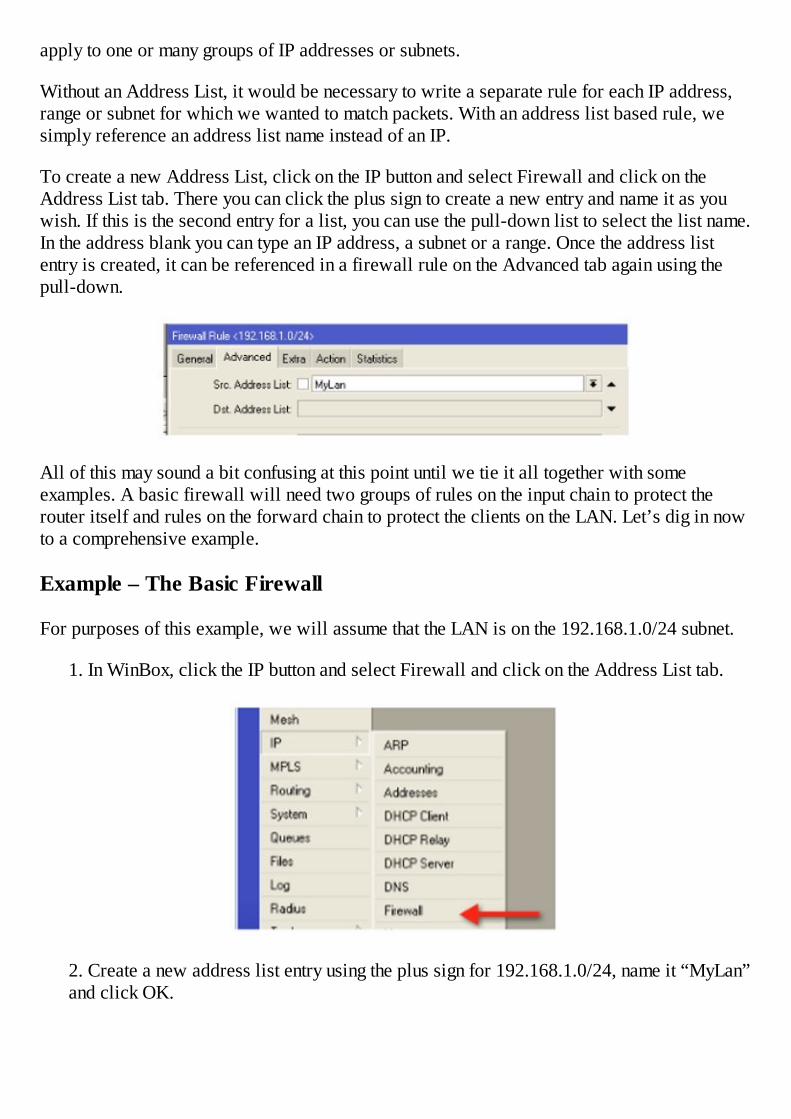
apply to one or many groups of IP addresses or subnets.
Without an Address List, it would be necessary to write a separate rule for each IP address,range or subnet for which we wanted to match packets. With an address list based rule, wesimply reference an address list name instead of an IP.
To create a new Address List, click on the IP button and select Firewall and click on theAddress List tab. There you can click the plus sign to create a new entry and name it as youwish. If this is the second entry for a list, you can use the pull-down list to select the list name.In the address blank you can type an IP address, a subnet or a range. Once the address listentry is created, it can be referenced in a firewall rule on the Advanced tab again using thepull-down.
All of this may sound a bit confusing at this point until we tie it all together with someexamples. A basic firewall will need two groups of rules on the input chain to protect therouter itself and rules on the forward chain to protect the clients on the LAN. Let’s dig in nowto a comprehensive example.
Example – The Basic Firewall
For purposes of this example, we will assume that the LAN is on the 192.168.1.0/24 subnet.
1. In WinBox, click the IP button and select Firewall and click on the Address List tab.
2. Create a new address list entry using the plus sign for 192.168.1.0/24, name it “MyLan”and click OK.

3. Click the IP button, select Firewall and the Filter tab. Click the plus sign to create anew rule.
Rule 1: On the chain, select “input”. On the connection state select “invalid” and on theaction tab select “drop”.
Rule 2: Click the plus sign to create a new rule.
On the chain, select “forward”. On the connection state select “invalid” and on theaction tab select “drop”.

These two rules drop invalid connections to and through the router.
Rule 3: Click the plus sign to create a new rule.
On the chain, select “input”. On the advanced tab select “Src. Address List” and on thepull-down select the new entry you just created for “MyLan”. On the Action tab select“accept”. This rule will allow anyone on your LAN to administer the router. Obviously,you can be more restrictive if you wish.
Rule 4: Click the plus sign to create a new rule.
On the chain, select “input”. On the “Connection State” select “established” and on the“Action” tab select “accept”. This rule will allow our router to communicate with otherhosts for services like ping or telnet.
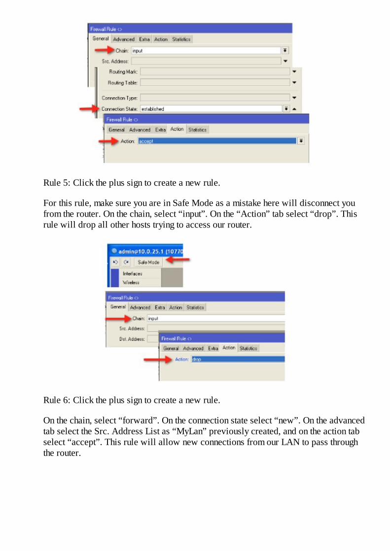
Rule 5: Click the plus sign to create a new rule.
For this rule, make sure you are in Safe Mode as a mistake here will disconnect youfrom the router. On the chain, select “input”. On the “Action” tab select “drop”. Thisrule will drop all other hosts trying to access our router.
Rule 6: Click the plus sign to create a new rule.
On the chain, select “forward”. On the connection state select “new”. On the advancedtab select the Src. Address List as “MyLan” previously created, and on the action tabselect “accept”. This rule will allow new connections from our LAN to pass throughthe router.

Rule 7: Click the plus sign to create a new rule.
On the chain, select “forward”. On the connection state select “related” and on theaction tab select “accept”. This rule will allow related connections through the router.
Rule 8: Click the plus sign to create a new rule.
On the chain, select “forward”. On the connection state select “established” and on theaction tab select “accept”. This rule will allow established connections through therouter.
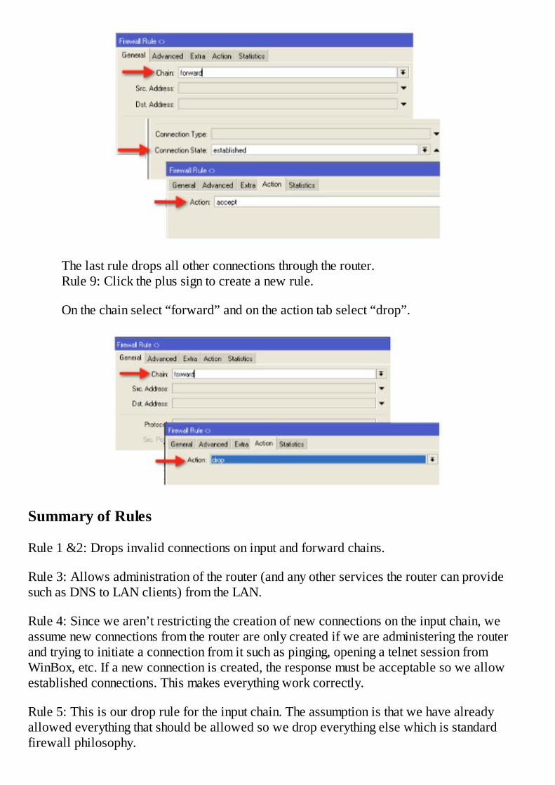
The last rule drops all other connections through the router. Rule 9: Click the plus sign to create a new rule.
On the chain select “forward” and on the action tab select “drop”.
Summary of Rules
Rule 1 &2: Drops invalid connections on input and forward chains.
Rule 3: Allows administration of the router (and any other services the router can providesuch as DNS to LAN clients) from the LAN.
Rule 4: Since we aren’t restricting the creation of new connections on the input chain, weassume new connections from the router are only created if we are administering the routerand trying to initiate a connection from it such as pinging, opening a telnet session fromWinBox, etc. If a new connection is created, the response must be acceptable so we allowestablished connections. This makes everything work correctly.
Rule 5: This is our drop rule for the input chain. The assumption is that we have alreadyallowed everything that should be allowed so we drop everything else which is standardfirewall philosophy.

Rule 6: This is where we control the creation of new connections and restrict them only toconnections that are sourced from our LAN.
Rule 7: Since we restricted new connections in step 6. Now we allow related connections.
Rule 8: Since we restricted new connections in step 6. Now we allow establishedconnections.
Rule 9: This is our drop rule for the forward chain. The assumption is that we have alreadyallowed everything that should be allowed so drop everything else, standard firewallphilosophy.
This example can be extended and serves only as the foundation of a stateful firewall. If youwant to restrict certain protocols, for instance, SSH from the LAN, it is now fairly simple tocreate a rule to drop that protocol on the forward chain by matching port 22 with an action ofdrop. Put that rule at or near the top of your list and LAN clients will not be able to initiateSSH connections outside the firewall.
For Further Study: RouterOS also offers some “smart” rules to detect port scans, matchconnections, and many other more complex functions that are outside the scope of this book.

Chapter 9 – NAT, Network Address Translation
In the previous chapter hopefully it was made clear the importance of understanding thesource IP, destination IP, source port, and destination port of an IP packet with respect tofirewalls. Combined with connection states, these four simple pieces of information can beleveraged to assemble powerful firewalls that rival equipment costing many times more than aMikroTik RouterOS device. In addition to the firewall function, these four pieces ofinformation can be tracked and manipulated using a function called NAT or Network AddressTranslation.
NAT is the process of changing the original source IP, destination IP, source port, ordestination port of an IP packet. It allows functions such as masquerading, which is hiding aprivate network behind a public network address. It also allows the opposite function,destination NAT, allowing public access to a private server.
NAT functions, similar to firewall functions, are organized in chains. The default chains are:
1. Source NAT (“srcnat”), that is changing the source IP address of the packet.2. Destination NAT (“dstnat”), which is changing the destination IP address of the packet.
Source NAT
With source NAT, the most common function is masquerading, hiding a private networkbehind a public address. This function allows a router with a single public IP address tofunction as an Internet gateway for a handful or even thousands of hosts or computers locatedbehind the device on a private network. Like all NAT functions, the process is fairly simple;change the source or destination IP address or port based on a rule. Like all firewallfunctions, the rule itself is based on a packet matcher. The most simple source NAT rule, themasquerade rule, simply involves configuring the chain as “srcnat”, matching packets going tothe Internet by matching the “out interface”, and setting an action of masquerade.
The first matcher “srcnat” tells the router to strip off the source IP address from the packet. Inthis case, the source IP address will be the private address of the host or computer on the192.168.1.0/24 network. For example, if a host at 192.168.1.2 sends a packet to the Internet, itwill be sourced as 192.168.1.2 when it enters our firewall. Since the rule is a source NATrule, the router knows to strip the source IP address. The second packet matcher “outinterface” tells the router to only apply the rule to packets leaving interface ether1, which isthe interface, connected to the Internet in this example. The action of “masquerade” tells therouter to exchange the source IP address (the private IP) for its own IP bound to the interfacefrom which the packet is leaving (the public IP). Once the switch is done, the departing packetno longer is sourced from 192.168.1.2, instead it is sourced from the public IP of the router.Once this is done, the router makes a record of the source and destination IP addresses andports in its connection tracking table.
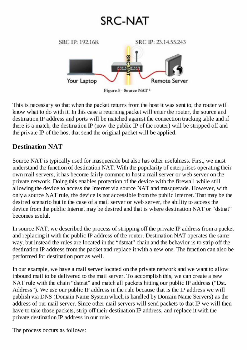
This is necessary so that when the packet returns from the host it was sent to, the router willknow what to do with it. In this case a returning packet will enter the router, the source anddestination IP address and ports will be matched against the connection tracking table and ifthere is a match, the destination IP (now the public IP of the router) will be stripped off andthe private IP of the host that send the original packet will be applied.
Destination NAT
Source NAT is typically used for masquerade but also has other usefulness. First, we mustunderstand the function of destination NAT. With the popularity of enterprises operating theirown mail servers, it has become fairly common to host a mail server or web server on theprivate network. Doing this enables protection of the device with the firewall while stillallowing the device to access the Internet via source NAT and masquerade. However, withonly a source NAT rule, the device is not accessible from the public Internet. That may be thedesired scenario but in the case of a mail server or web server, the ability to access thedevice from the public Internet may be desired and that is where destination NAT or “dstnat”becomes useful.
In source NAT, we described the process of stripping off the private IP address from a packetand replacing it with the public IP address of the router. Destination NAT operates the sameway, but instead the rules are located in the “dstnat” chain and the behavior is to strip off thedestination IP address from the packet and replace it with a new one. The function can also beperformed for destination port as well.
In our example, we have a mail server located on the private network and we want to allowinbound mail to be delivered to the mail server. To accomplish this, we can create a newNAT rule with the chain “dstnat” and match all packets hitting our public IP address (“Dst.Address”). We use our public IP address in the rule because that is the IP address we willpublish via DNS (Domain Name System which is handled by Domain Name Servers) as theaddress of our mail server. Since other mail servers will send packets to that IP we will thenhave to take those packets, strip off their destination IP address, and replace it with theprivate destination IP address in our rule.
The process occurs as follows:

Once again, connection tracking tracks the source and destination IP address and ports andthereby knows what to do with the packet when it is returned by the target host.Destination NAT’s do not have to use the same port from the packet matcher on the action tab,instead, we can change the port as well as the IP address if desired. For example, a packetentering the router on port 80 (typical HTTP or web port) can be translated to port 8080 onour internal web server. This allows us to use port 80 on the web server for a differentfunction like a local intranet. The port change is made on the action tab, an example of whichfollows hereafter. Why would you want to do that? One application is an office that has asingle public IP address. Their web server is hosted on the private network and operates onport 80 and they want to give the public access to their web site. The same company operatesa second private web server on a separate host server that runs a web server on port 80 fortheir partners. With only one public IP address and two web server machines that run theirweb service on port 80, we now have a quandary. The answer lies in using destination NATto change the destination port.
Host 1 – Public Web Server
Public IP: 12.238.96.5, standard HTTP port 80
Private IP: 192.168.1.10, web service runs on standard HTTP port 80
Host 2 – Partner Web Server
Public IP: 12.238.96.5, non-standard port 8080
Private IP: 192.168.1.11, web service runs on standard HTTP port 80
Now we need two NAT rules:
The first rule is the dstnat chain, protocol TCP, destination port 80, action destination NAT,destination IP is 192.168.1.10 and the destination port is 80.

The second rule is the dstnat chain, protocol TCP, destination port 8080, action destinationNAT, destination IP is 192.168.1.11 and the destination port is 80.
To summarize these processes, NAT is simply the function of changing or manipulating thesource or destination IP address and/or ports of packets entering or leaving the router. Insimple terms, source NAT refers to packets leaving the router and destination NAT refers topackets entering the router. The most common us of source NAT is for the masqueradingaction and the most common type of destination NAT is to NAT a public IP to a private IP.
Special Types of NAT Rules
Source NAT With Multiple Public IP Addresses
If you have a single public IP address on your Internet facing interface and a default route toyour provider on that subnet, it is fairly easy to see that any packets processed by themasquerade rule will result in packets being sourced from your router’s public IP address. Inmany scenarios this is acceptable but what if you add a secondary IP to the Internet facinginterface on a different subnet and use that IP for a mail server located on the privatenetwork? With the amount of unsolicited email (SPAM) that is processed every day by mailservers around the globe, careful controls are now in place almost universally to control theorigin of emails. One of these controls is reverse DNS, the ability to look up the sourceaddress of the mail server trying to deliver mail to our mail server and ensure it is a memberof the domain name, which it reports to be. In the preceding example, if the forward DNSentry for our mail server resolves to the secondary IP address on our router and the reverseDNS is set the same, we would need a way to manipulate packets such that, the source IP ofall packets leaving our mail server is set to the secondary address. This would not be thenormal behavior for a single source NAT rule with the action masquerade.
Here is an example:
Public IP of our router: 23.0.12.2
Default gateway of our router: 23.0.12.1
Mail Server private IP: 192.168.1.2
Secondary public IP used for inbound access to our mail server: 23.0.12.3
For inbound email, if we use a destination NAT rule to receive mail on 23.0.12.3 anddestination NAT it to 192.168.1.2, that works well, however, with only a masquerade inplace to masquerade everything leaving our public interface, all traffic including mail beingsent by our mail server will be sourced from 23.0.12.2, thereby breaking mail. The solutionhere is a source NAT rule. The rule would match packets coming from 192.168.1.2 and havean action or source NAT to IP address 23.0.12.3. This rule solves the issue.
Destination NAT with Action Redirect

Each of the actions you set for a NAT rule accomplishes a more complex function in thebackground. The masquerade action for instance strips the source IP and applies the router’spublic (outgoing) IP while destination NAT strips the destination IP address or port andapplies a different destination IP address or port. There is another useful action called“redirect” that is often used for certain applications.
Consider an example. You operate a network and use your upstream provider’s DNS serversfor your customers. Many of your customers have static IP’s and static DNS entries. Forwhatever reason the decision is made to change upstream providers, however, your currentprovider does not allow DNS resolution from IP’s outside its network. Obviously you coulduse a NAT rule with masquerade to masquerade the old provider’s public IP’s and treat themas private IP’s while you are transitioning over to the new provider, but what about the staticDNS entries? This is where the redirect action can step in.
Think of redirect as a transparent NAT, it transparently applies a NAT action to packetsbased on matching criteria. The other important thing to remember for a redirect rule is that it“captures” the traffic and processes it on the router itself. This is a different action than adestination NAT rule with an action of destination NAT.
To summarize the difference between these two types of rules, think of it like this: A NATrule with an action of destination NAT sends the traffic to a host while a destination NAT rulewith an action of redirect “captures” the traffic and processes it on the router.
Getting back to our example, we can remedy the DNS issue by capturing the DNS requests onthe router and processing them there using the router’s internal caching DNS server. We willdiscuss caching DNS later in this book, but let it suffice to say for now we have alreadyconfigured caching DNS on the router and it is able to resolve DNS requests from the newprovider’s DNS servers. In this case, simply create a new destination NAT rule withmatchers for protocol TCP, port 53, and an action of redirect to port 53. The second rule weneed is a duplicate of the first with a protocol of UDP. These two rules will capture all DNSrequests trying to go to our old provider’s DNS servers and answer them on the router itself.We can then take our time doing the IP transition on the network to the new provider’s IP’s.
Another example of using redirect is to create a transparent proxy. If we aren’t familiar withproxy servers (the most popular one is called Squid), their function is to accept web requests(HTTP traffic) and then proxy those requests to the public network. These pages fetched maybe stored in memory or on disk for later serving to proxy clients. This speeds up networkaccess, enables the use of access rules to restrict use of the Internet, and gives the ability toredirect web pages, or many other useful functions described later in this book under the IPWeb Proxy function.
If we want this function to be applied without the knowledge of your clients or users andwithout intervention on their part, again a redirect rule is the answer. In this scenario, create anew destination NAT rule matching protocol TCP, port 80, with an action of redirect to port8080 (or whatever port we have IP Web Proxy running on at the router). Once configured, allHTTP requests to the Internet will be intercepted at the router and handled by the proxyserver.

Example – A Simple Masquerade Rule
For purposes of this example, we will assume the Internet is connected to ether1.
1. Create a new Nat rule using IP button then Firewall and then click the NAT tab andthe plus sign.
2. Select the chain “srcnat” and set the outgoing interface to ether1.
3. Select the Action tab and select “masquerade”.
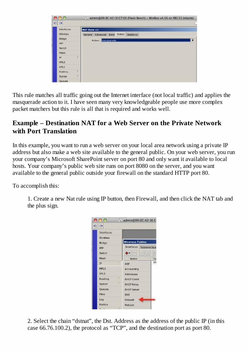
This rule matches all traffic going out the Internet interface (not local traffic) and applies themasquerade action to it. I have seen many very knowledgeable people use more complexpacket matchers but this rule is all that is required and works well.
Example – Destination NAT for a Web Server on the Private Networkwith Port Translation
In this example, you want to run a web server on your local area network using a private IPaddress but also make a web site available to the general public. On your web server, you runyour company’s Microsoft SharePoint server on port 80 and only want it available to localhosts. Your company’s public web site runs on port 8080 on the server, and you wantavailable to the general public outside your firewall on the standard HTTP port 80.
To accomplish this:
1. Create a new Nat rule using IP button, then Firewall, and then click the NAT tab andthe plus sign.
2. Select the chain “dstnat”, the Dst. Address as the address of the public IP (in thiscase 66.76.100.2), the protocol as “TCP”, and the destination port as port 80.

3. On the action tab, select the action “dst-nat”, the destination address as the private IPof your web server, and the destination port as 8080.
The rule matches all TCP packets going to the public IP on port 80, strips the destinationaddress, and replaces it with the private IP address of the web server. It also replaces thedestination port with port 8080. To the outside world, there appears to be a web serverrunning on port 80 on 66.76.100.2.
Example – Source NAT to Source Traffic From a Certain IP Address
The example above assumes that you only have a single IP address on your public facinginterface. In some setups, you may have multiple public IP addresses on some or all interfacesincluding the public facing interface. In this scenario, traffic being masqueraded by the routerwith a single masquerade rule and no other NAT rules will generally be sourced from the IPaddress that is common to the default route. This is certainly true in the example describedabove.
To be clear, if your public IP is 66.76.100.2 and your default gateway is 66.76.100.1, anytraffic that goes out the public interface will be sourced from 66.76.100.2 even if other IP’sare bound to that interface. So, what if you get another IP address from your provider for anew web server to operate publically on 66.76.100.3, and you create a destination NAT rulesimilar to the example above for this new IP to go to 192.168.1.10? This will work fine butfor the fact that traffic leaving the router will still be sourced from 66.76.100.2. This may

appear to work but it may break certain protocols or cause other issues. To solve this problemwe can use source NAT.
1. Create a new Nat rule using IP button, then Firewall, the NAT tab, and then the plussign.
2. Create a new NAT rule in the “srcnat” chain.
3. On the Action tab, select the action “src-nat” and the To Address as 66.76.100.3.
This rule matches all traffic coming from the new web server, strips the source address, andreplaces it with the secondary public IP 66.76.100.3 for outbound traffic.
In this scenario, two rules are needed: one to destination NAT inbound traffic on TCP port 80

to go 192.168.1.10 and one to source any traffic from 192.168.1.10 from 66.76.100.3 as itleaves the router.
Example – Destination NAT with the Action Redirect
In this example, we want to “trap” all DNS outbound traffic from the local area network andprocess the DNS requests on our Internet router. We have already configured the caching DNSserver on the router and now only need to intercept UDP and TCP port 53 packets.
1. Create a new Nat rule using IP button, Firewall, the NAT tab and then the plus sign.
2. Select the protocol as “TCP” and the destination port as port 53.
3. On the action tab, select the action “redirect”.
4. Repeat the process for UDP port 53.

These rules will match all DNS packets, (UDP and TCP), intercept them, and process directlyon the router. This example is useful when you want to force the use of your DNS server.
Service Ports - NAT Helpers
You will likely never find yourself looking for the menu to configure NAT helpers as thisfeature is seldom changed and usually only discovered by accident. If you happen to click theIP button and then select Firewall and click on the Service Port tab, there you will see theNAT Helpers that have been included with the NAT facility. These modules, enabled bydefault, can be disabled or manipulated by changing the port on which they operate. Theirfunction is to “help” certain protocols by identifying packets that are using that protocol.Connection tracking can be given knowledge of application-layer protocols and thusunderstand that two or more distinct connections are “related”. A great example of this isFTP, or File Transfer Protocol. During a FTP session, a control connection is established, butwhenever data is transferred, a separate connection is established to transfer it. The functionof the NAT helper is to identify the first packet of a new FTP control connection so that thedata connection will be marked as “related” instead of “new”, as it is logically part of anexisting connection.
Typically, there is no reason to make changes to these Service Ports unless you are runningthese protocols on non-standard ports. There is also no reason to disable them. Simply knowthey are there to make NAT work better and leave them alone.
Connection Tracking (on and off)
By default, connection tracking sometimes called “conntrack” is turned on. As previouslystated, connection tracking is the facility that makes RouterOS a stateful firewall and enablesNAT and filter rules. Turning it off will disable both NAT and firewall functions completelyso it is typically a good idea to leave it alone. However, there is always an exception to therule and in this case, there may be an application where turning it off is desired. For example,if a router is located in the interior of a secure network, that is, it has no access from theoutside world and no chance of being attacked, turning connection tracking off will make aconsiderable improvement in the performance of the router. It will be able to route morepackets faster because it isn’t using resources for tracking connections. Again, this willdisable NAT so it can not be turned off on an Internet or gateway router or firewall.
One example of where you might want to turn connection tracking off is a device that has awireless interface bridged to an Ethernet interface. Turning connection tracking off willimprove the performance of the wireless link provided that is the limiting factor and thereisn’t an issue with interference, Fresnel zone encroachment, and the like.
To further quantify the increase in performance by turning off connection tracking, considerthe published performance of the RouterBOARD 750 with connection tracking off.
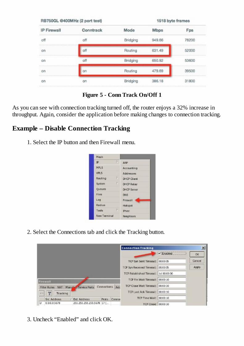
Figure 5 - Conn Track On/Off 1
As you can see with connection tracking turned off, the router enjoys a 32% increase inthroughput. Again, consider the application before making changes to connection tracking.
Example – Disable Connection Tracking
1. Select the IP button and then Firewall menu.
2. Select the Connections tab and click the Tracking button.
3. Uncheck “Enabled” and click OK.

Connection tracking is now disabled.
Tools – Torch
Having used equipment for many years from many different manufacturers, I would have tosay that one feature that really makes RouterOS stand head and shoulders above the rest is thenumber of tools that are available to the user inside the user interface. I would venture to saythat RouterOS has the most tools, more than any other software, and Torch is one of those veryuseful tools.
Torch is a real-time tool that will give you an instant picture of all traffic passing through aninterface. Better yet, it gives you the ability to sort that traffic and filter by IP address andport, and the ability to sort the traffic ascending or descending by rate. By using torch, youinstantly know who is using your bandwidth and how they are using it. It is great fordetermining the effectiveness of queues and firewall rules in real-time. Torch is available inmany different places in RouterOS such as by right clicking queues, interfaces, or through theTools menu by selecting Torch.
Once torch loads, you will be presented with a display that allow you to select the interface tobe monitored, as well as defining several filters to further restrict the traffic that is observed.
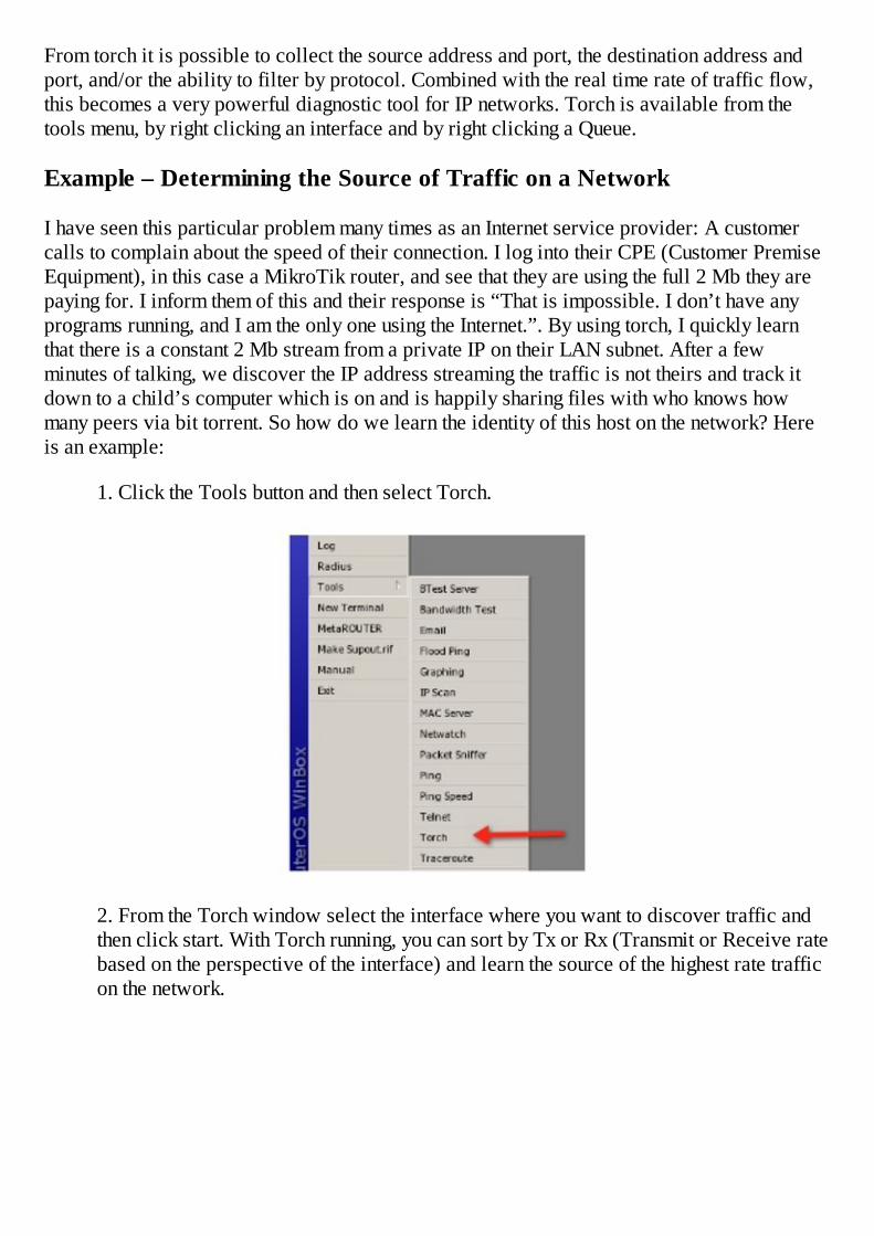
From torch it is possible to collect the source address and port, the destination address andport, and/or the ability to filter by protocol. Combined with the real time rate of traffic flow,this becomes a very powerful diagnostic tool for IP networks. Torch is available from thetools menu, by right clicking an interface and by right clicking a Queue.
Example – Determining the Source of Traffic on a Network
I have seen this particular problem many times as an Internet service provider: A customercalls to complain about the speed of their connection. I log into their CPE (Customer PremiseEquipment), in this case a MikroTik router, and see that they are using the full 2 Mb they arepaying for. I inform them of this and their response is “That is impossible. I don’t have anyprograms running, and I am the only one using the Internet.”. By using torch, I quickly learnthat there is a constant 2 Mb stream from a private IP on their LAN subnet. After a fewminutes of talking, we discover the IP address streaming the traffic is not theirs and track itdown to a child’s computer which is on and is happily sharing files with who knows howmany peers via bit torrent. So how do we learn the identity of this host on the network? Hereis an example:
1. Click the Tools button and then select Torch.
2. From the Torch window select the interface where you want to discover traffic andthen click start. With Torch running, you can sort by Tx or Rx (Transmit or Receive ratebased on the perspective of the interface) and learn the source of the highest rate trafficon the network.
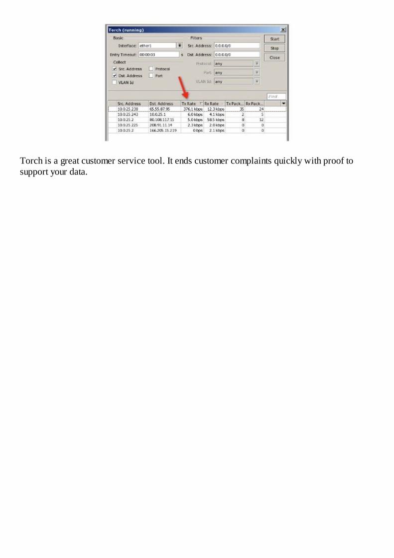
Torch is a great customer service tool. It ends customer complaints quickly with proof tosupport your data.


Chapter 10 - Bandwidth Limits
If I had to name one area where I see the greatest interest in RouterOS, it has to be withbandwidth limitation and Quality of Service or QOS. These two topics really go hand in hand,and incorporating them into your network will almost certainly “tame the savage beast” or atleast fend off the gremlins that are stalking your network, trying to steal your resources.RouterOS offers several schemes to control bandwidth and each has its benefits and costs.
Simple Queues
I always begin my classroom instruction on simple queues by saying “The best thing aboutsimple queues is that they are simple, and the worst thing about simple queues is that they aresimple.” Simple queues are intelligent little modules that were created to allow you a simpleand fast means of limiting bandwidth. They are extremely powerful in what they do behind thescenes and they allow even a RouterOS novice to quickly implement a basic bandwidthlimitation and QoS system. The price you pay for using them is paid in CPU resources. Eachsimple queue you create also creates several hidden queues in the background that perform themore complex function configured by the simple queue.
That being said, it is important to use them sparingly. For a more evolved queuing system, relyon more complex queues that are actually more efficient in their operation. For example, PCCor Per Connection Classifiers enable you to create a handful of queues that can controlbandwidth for thousands of clients. These will be discussed later in this chapter.
Simple queues are configured by referencing the target address of the device you are trying tocontrol bandwidth to and then initiating a limit for upload and download. This “device”referenced here is typically a customer or client. These are the only pieces of information thatneed to be configured to have a working queuing system. To further explain let’s look at anexample.
Simple queues are configured from the Queues menu on the Simple Queues tab.
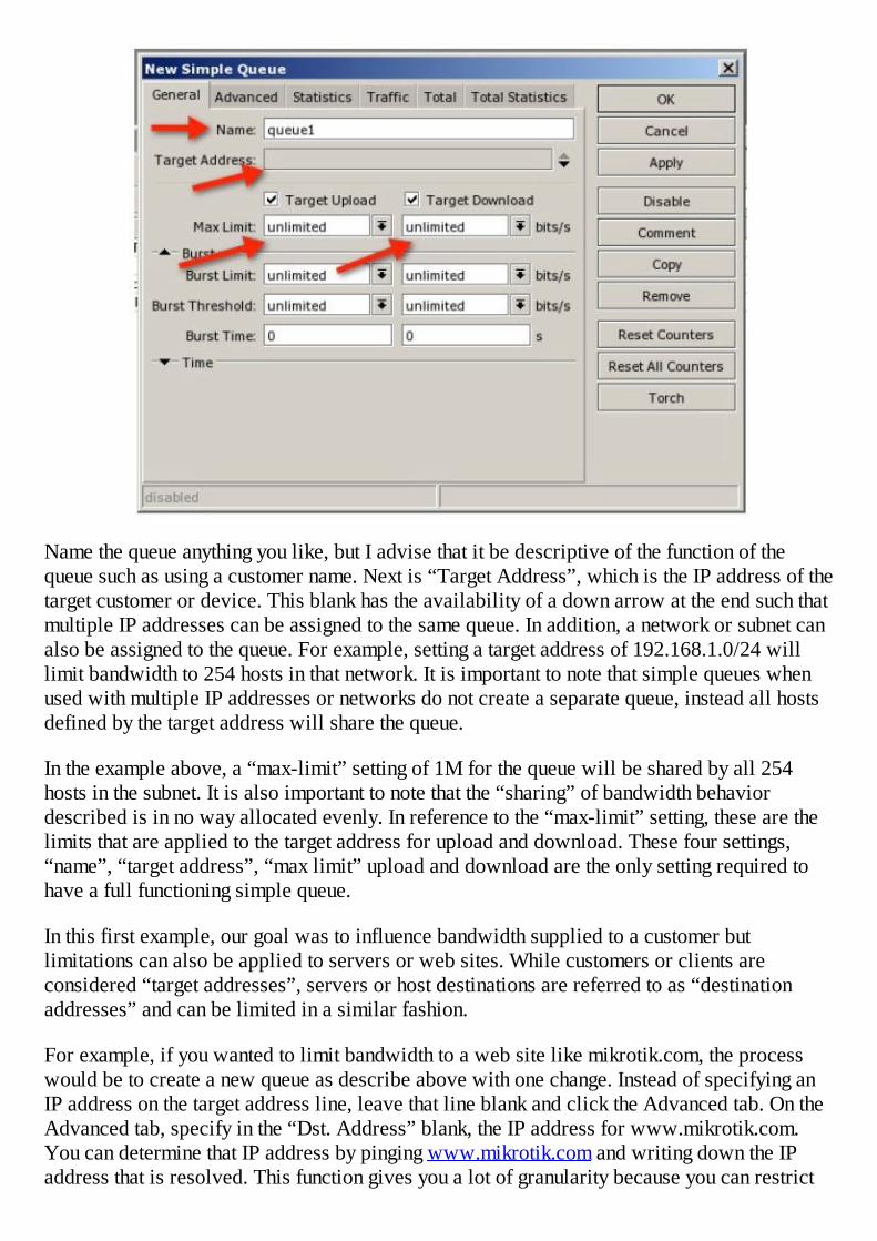
Name the queue anything you like, but I advise that it be descriptive of the function of thequeue such as using a customer name. Next is “Target Address”, which is the IP address of thetarget customer or device. This blank has the availability of a down arrow at the end such thatmultiple IP addresses can be assigned to the same queue. In addition, a network or subnet canalso be assigned to the queue. For example, setting a target address of 192.168.1.0/24 willlimit bandwidth to 254 hosts in that network. It is important to note that simple queues whenused with multiple IP addresses or networks do not create a separate queue, instead all hostsdefined by the target address will share the queue.
In the example above, a “max-limit” setting of 1M for the queue will be shared by all 254hosts in the subnet. It is also important to note that the “sharing” of bandwidth behaviordescribed is in no way allocated evenly. In reference to the “max-limit” setting, these are thelimits that are applied to the target address for upload and download. These four settings,“name”, “target address”, “max limit” upload and download are the only setting required tohave a full functioning simple queue.
In this first example, our goal was to influence bandwidth supplied to a customer butlimitations can also be applied to servers or web sites. While customers or clients areconsidered “target addresses”, servers or host destinations are referred to as “destinationaddresses” and can be limited in a similar fashion.
For example, if you wanted to limit bandwidth to a web site like mikrotik.com, the processwould be to create a new queue as describe above with one change. Instead of specifying anIP address on the target address line, leave that line blank and click the Advanced tab. On theAdvanced tab, specify in the “Dst. Address” blank, the IP address for www.mikrotik.com.You can determine that IP address by pinging www.mikrotik.com and writing down the IPaddress that is resolved. This function gives you a lot of granularity because you can restrict
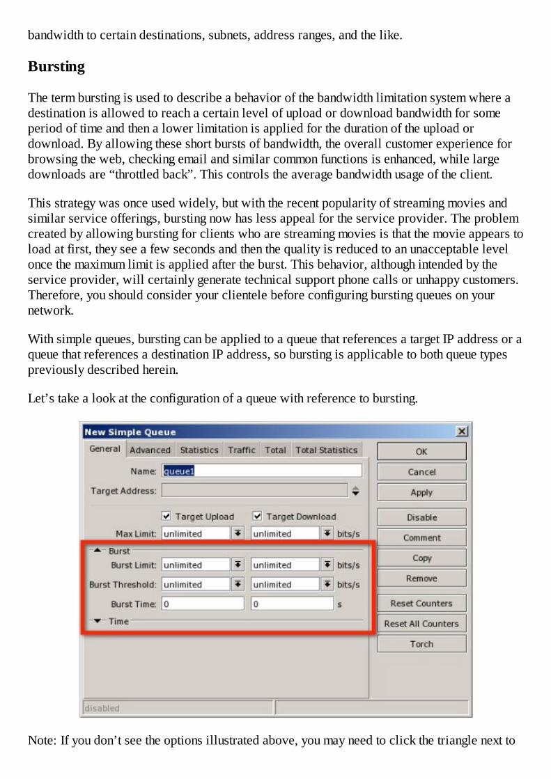
bandwidth to certain destinations, subnets, address ranges, and the like.
Bursting
The term bursting is used to describe a behavior of the bandwidth limitation system where adestination is allowed to reach a certain level of upload or download bandwidth for someperiod of time and then a lower limitation is applied for the duration of the upload ordownload. By allowing these short bursts of bandwidth, the overall customer experience forbrowsing the web, checking email and similar common functions is enhanced, while largedownloads are “throttled back”. This controls the average bandwidth usage of the client.
This strategy was once used widely, but with the recent popularity of streaming movies andsimilar service offerings, bursting now has less appeal for the service provider. The problemcreated by allowing bursting for clients who are streaming movies is that the movie appears toload at first, they see a few seconds and then the quality is reduced to an unacceptable levelonce the maximum limit is applied after the burst. This behavior, although intended by theservice provider, will certainly generate technical support phone calls or unhappy customers.Therefore, you should consider your clientele before configuring bursting queues on yournetwork.
With simple queues, bursting can be applied to a queue that references a target IP address or aqueue that references a destination IP address, so bursting is applicable to both queue typespreviously described herein.
Let’s take a look at the configuration of a queue with reference to bursting.
Note: If you don’t see the options illustrated above, you may need to click the triangle next to

the word “Burst” to expand the burst section.
The settings that configure burst are “Burst Limit”, “Burst Threshold” and “Burst Time”.
Quoting from the MikroTik Wiki:
burst-limit (NUMBER): maximal upload/download data rate which can be reached while theburst is allowed.
burst-time (TIME) : period of time, in seconds, over which the average data rate iscalculated. (This is NOT the time of actual burst).
burst-threshold (NUMBER) : this is value of burst on/off switch.
Of these values, the first appears fairly obvious; “burst-limit” is the maximum bandwidth youare going to allow during this bursting period. Slightly less obvious is the burst threshold.Think of the burst threshold as an on/off switch. When we hit the value of the burst threshold,the timer starts and we are allowed to burst up to the burst limit for some period of time. Ihave seen many theories on the proper setting of the burst threshold but for purposes of ourdiscussion, I rely on the MikroTik RouterOS manual, which states that for the optimalperformance, the burst-threshold must be less than the max-limit, which must be less than theburst-limit or stating it another way:
burst-threshold < max-limit < burst-limit
That having been said, what is the optimal setting for burst-threshold? I recommend setting itat half the max-limit because it is an easy calculation and it satisfies the premise that theburst-threshold be less than the max-limit as prescribed by the manual.
The final setting required is the burst time. Again, referring back to the manual “The actualduration of burst does not depend on burst-time alone. It also depends on the burst-threshold/burst-limit ratio and the actual data rate passing through the bursting class.” Whatdoes that exactly mean? I can demonstrate through the use of a formula. To calculate the bursttime, use the following method:
First, calculate the burst ratio as follows:
Burst Ratio = burst-threshold/burst-limit
Then, calculate the burst time:
Burst Time = (Clock Time to Burst) /(Burst Ratio)
To summarize, here is an example.
Given:
We want to create a simple queue with a 256k max-limit andwe want to burst to 512k for 5 seconds on the clock.

Therefore:
Max-Limit: 256k (given)Burst-Limit: 512k (given)Burst-Threshold: 128k (half the max-limit as recommended above)Burst-Time: 20s
We calculate the burst time as follows:
Burst Ratio = 128k/512k = .25Burst Time = 5sec / .25 = 20
Therefore, if we set the burst time to 20, we will get the desired 5 second burst. It would begreat if the value of burst time was equal to clock time, but as you can see it isn’t. Thecalculation described here is required to get proper queue behavior.
Example – Creating a Simple Queue for Computers in an Office Network
For purposes of this example, we want to limit all computers on our 192.168.1.0/24 networkto share a 5 meg allocation of bandwidth. Remember that simple queues with the targetaddress set to a subnet do not allocate the queue amount to each computer in the subnet,instead it is shared by all IP addresses in the subnet as it is consumed. We will learn otherqueue strategies in future examples to create separate allocations of bandwidth.
1. Click the Queues button to open the Simple Queues list.
2. In the Simple Queues list, click the plus sign to create a new simple queue.
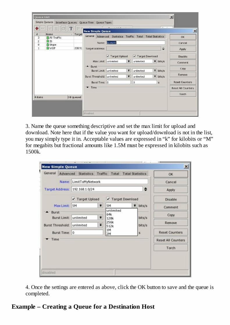
3. Name the queue something descriptive and set the max limit for upload anddownload. Note here that if the value you want for upload/download is not in the list,you may simply type it in. Acceptable values are expressed in “k” for kilobits or “M”for megabits but fractional amounts like 1.5M must be expressed in kilobits such as1500k.
4. Once the settings are entered as above, click the OK button to save and the queue iscompleted.
Example – Creating a Queue for a Destination Host

In this example, we want to limit bandwidth to a site such as www.mikrotik.com. To createthe queue, first we must know the IP address of that web host or the range of addresses thehost uses. By pinging www.mikrotik.com from a command line, we learn the IP address is159.148.147.196. Create this queue as follows:
1. Click the Queues button to open the simple queue list.
2. In the Simple Queues list, click the plus sign to create a new simple queue.
Name the queue as you like, and then click the Advanced tab. On the advanced tab, insert thevalue for the destination address, the IP address for www.mikrotik.com and the bandwidthrestrictions you want to impose.

3. Click OK and all traffic to and from MikroTik.com will be restricted to 1M.
Example – Create a Queue for Local Computers with Burst
In this example, we will use the calculated values from the previous section entitled“Bursting”.
1. Click the Queues button to open the Simple Queues list.
2. In the Simple Queues list, click the plus sign to create a new simple queue.
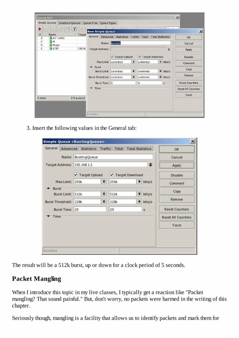
3. Insert the following values in the General tab:
The result will be a 512k burst, up or down for a clock period of 5 seconds.
Packet Mangling
When I introduce this topic in my live classes, I typically get a reaction like "Packetmangling? That sound painful." But, don't worry, no packets were harmed in the writing of thischapter.
Seriously though, mangling is a facility that allows us to identify packets and mark them for

later use. With this mark we can do wonderful things like force packets with certain marks totake certain routes, or go through certain queues. One concern of packet mangling is that it canbe very CPU intensive if we have to look at every single packet, make a decision whether ornot to mark it, and then perform the marking action. Fortunately, there is a method of markingpackets that uses an optimized scheme and therefore is much less intense. This method iscalled the "optimal mangle", named for the fact it optimizes the process and thereforeaccomplishes the task in the most CPU efficient manner.
There are two steps to the optimal mangle:
1. Identify connections that are flowing the packets we want to mangle.
2. Mark the packets.
To demonstrate why this is the most efficient method, I like to use the analogy of a worker in afactory on the final assembly line whose job it is to place a decal on completed products. Ifthere are a large variety of products passing in front of the inspector and his job is to onlymark a single product type, he spends a large portion of his time looking for the actual productto be decaled. It is like looking for a needle in a haystack. However, if we sort the productsfirst and only put on his conveyor belt the actual items he is to mark, his efforts are greatlyreduced. He only has to apply the decals and does not waste resources looking for theproducts. The optimal mangle works the same way.
Example – Packet Mangling Using Optimal Mangle
1. To perform the mangle, we create two rules in the IP Firewall list under the Mangletab.
2. Mangles are performed in a certain place within the routing process and theexplanation of each of these places or “chains” as they are called is outside the scope
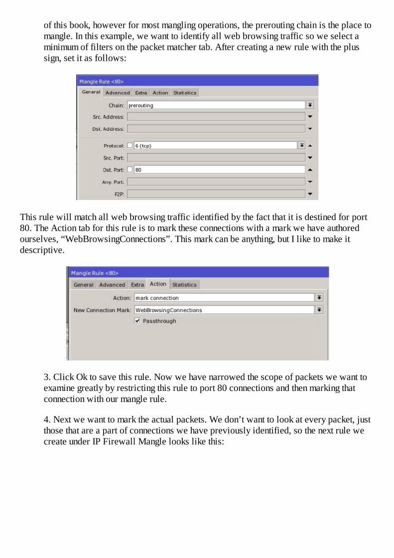
of this book, however for most mangling operations, the prerouting chain is the place tomangle. In this example, we want to identify all web browsing traffic so we select aminimum of filters on the packet matcher tab. After creating a new rule with the plussign, set it as follows:
This rule will match all web browsing traffic identified by the fact that it is destined for port80. The Action tab for this rule is to mark these connections with a mark we have authoredourselves, “WebBrowsingConnections”. This mark can be anything, but I like to make itdescriptive.
3. Click Ok to save this rule. Now we have narrowed the scope of packets we want toexamine greatly by restricting this rule to port 80 connections and then marking thatconnection with our mangle rule.
4. Next we want to mark the actual packets. We don’t want to look at every packet, justthose that are a part of connections we have previously identified, so the next rule wecreate under IP Firewall Mangle looks like this:
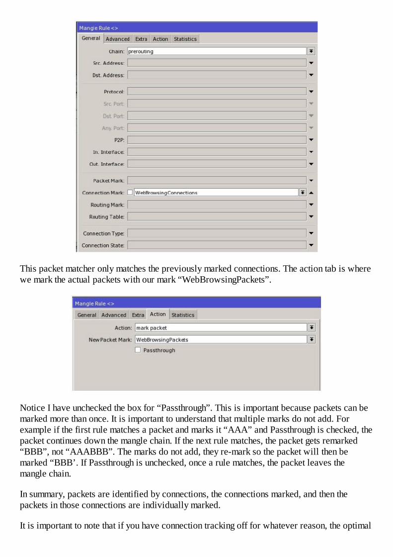
This packet matcher only matches the previously marked connections. The action tab is wherewe mark the actual packets with our mark “WebBrowsingPackets”.
Notice I have unchecked the box for “Passthrough”. This is important because packets can bemarked more than once. It is important to understand that multiple marks do not add. Forexample if the first rule matches a packet and marks it “AAA” and Passthrough is checked, thepacket continues down the mangle chain. If the next rule matches, the packet gets remarked“BBB”, not “AAABBB”. The marks do not add, they re-mark so the packet will then bemarked “BBB’. If Passthrough is unchecked, once a rule matches, the packet leaves themangle chain.
In summary, packets are identified by connections, the connections marked, and then thepackets in those connections are individually marked.
It is important to note that if you have connection tracking off for whatever reason, the optimal
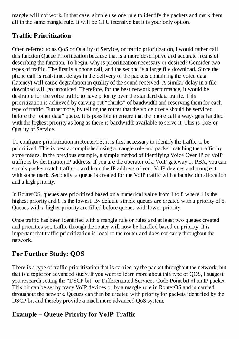
mangle will not work. In that case, simple use one rule to identify the packets and mark themall in the same mangle rule. It will be CPU intensive but it is your only option.
Traffic Prioritization
Often referred to as QoS or Quality of Service, or traffic prioritization, I would rather callthis function Queue Prioritization because that is a more descriptive and accurate means ofdescribing the function. To begin, why is prioritization necessary or desired? Consider twotypes of traffic. The first is a phone call, and the second is a large file download. Since thephone call is real-time, delays in the delivery of the packets containing the voice data(latency) will cause degradation in quality of the sound received. A similar delay in a filedownload will go unnoticed. Therefore, for the best network performance, it would bedesirable for the voice traffic to have priority over the standard data traffic. Thisprioritization is achieved by carving out “chunks” of bandwidth and reserving them for eachtype of traffic. Furthermore, by telling the router that the voice queue should be servicedbefore the “other data” queue, it is possible to ensure that the phone call always gets handledwith the highest priority as long as there is bandwidth available to serve it. This is QoS orQuality of Service.
To configure prioritization in RouterOS, it is first necessary to identify the traffic to beprioritized. This is best accomplished using a mangle rule and packet matching the traffic bysome means. In the previous example, a simple method of identifying Voice Over IP or VoIPtraffic is by destination IP address. If you are the operator of a VoIP gateway or PBX, you cansimply packet match traffic to and from the IP address of your VoIP devices and mangle itwith some mark. Secondly, a queue is created for the VoIP traffic with a bandwidth allocationand a high priority.
In RouterOS, queues are prioritized based on a numerical value from 1 to 8 where 1 is thehighest priority and 8 is the lowest. By default, simple queues are created with a priority of 8.Queues with a higher priority are filled before queues with lower priority.
Once traffic has been identified with a mangle rule or rules and at least two queues createdand priorities set, traffic through the router will now be handled based on priority. It isimportant that traffic prioritization is local to the router and does not carry throughout thenetwork.
For Further Study: QOS
There is a type of traffic prioritization that is carried by the packet throughout the network, butthat is a topic for advanced study. If you want to learn more about this type of QOS, I suggestyou research setting the “DSCP bit” or Differentiated Services Code Point bit of an IP packet.This bit can be set by many VoIP devices or by a mangle rule in RouterOS and is carriedthroughout the network. Queues can then be created with priority for packets identified by theDSCP bit and thereby provide a much more advanced QoS system.
Example – Queue Priority for VoIP Traffic

In this example, we are a service provider and we desire to prioritize VoIP traffic to and fromour imaginary VoIP gateway which is located at IP address 212.13.14.2. There is one routerbetween our clients and the VoIP gateway and that is where we will create the QoS system
1. To begin, we want to create a Mangle Rule for traffic destined for the VoIP gatewayand traffic from the VoIP gateway. We will use the technique previously discussed formarking connections first and then marking packets. This is done with a mangle rules asfollows:
This rule matches packets coming from our VoIP gateway.
On the action tab, we are marking these connections with the connection mark “VoIP”.
2. Next, we create a rule for traffic in the opposite direction, that is, traffic going to theVoIP gateway.
The Action will be the same, mark the connection.

3. The last mangle rule will match the connection mark and then mark the actual VoIPpackets.
Note that we uncheck “Passthrough” so that the packets will not get remarked.
4. Next we create two queues, one for VoIP and one for everything else. In this examplewe have a T1 connection, or approximately 1.5 megabits of bandwidth. We choose toallocate 512k for VoIP and the remainder for all other traffic.
The queues are created as follows:

Note that we are identifying traffic with the packet mark “VoIP” and setting this queue priorityto 1.
5. Finally, we need a queue for all other traffic and here we can make use of a littleknow feature, the packet mark “no-mark”. If a packet is not mangled, it is still actuallymarked with the mark “no-mark”. So, even without a mangle rule for all other traffic,we can queue based on this unmarked status of mark “no-mark”.
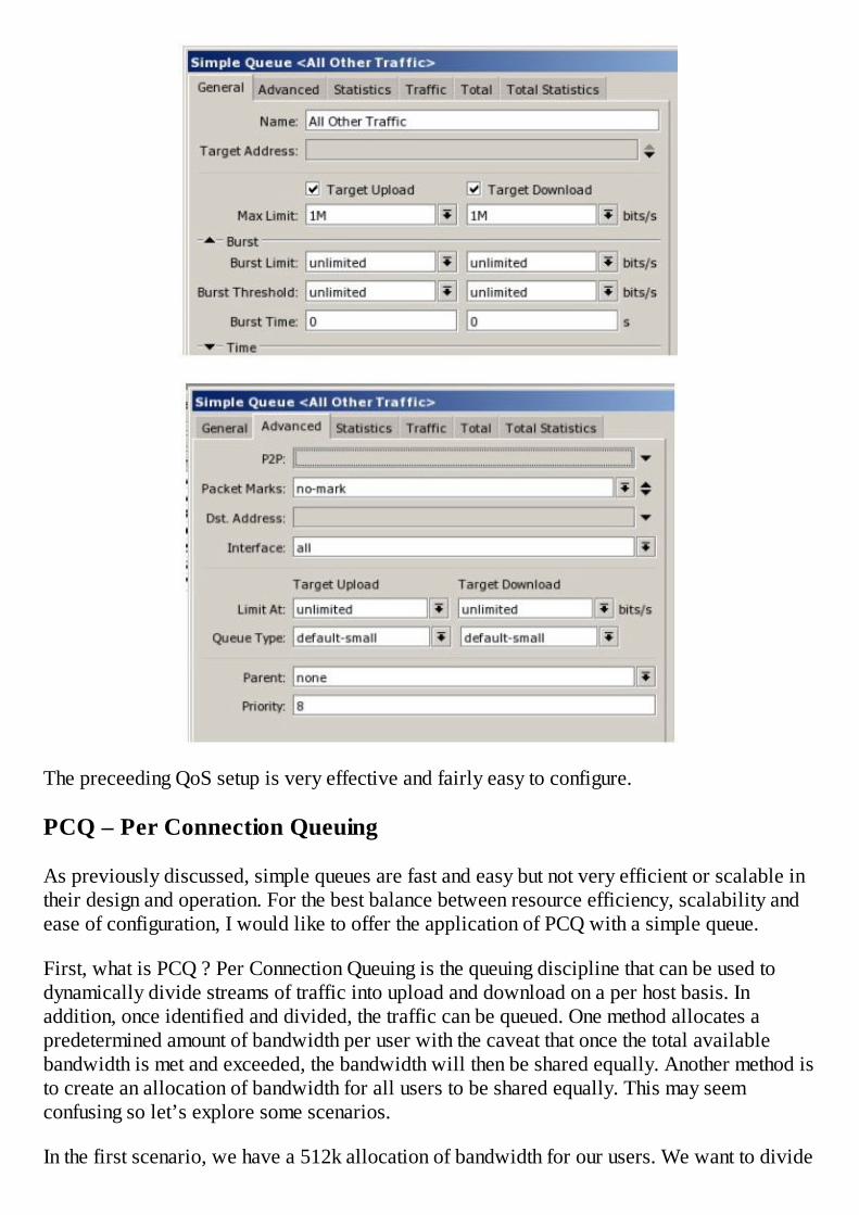
The preceeding QoS setup is very effective and fairly easy to configure.
PCQ – Per Connection Queuing
As previously discussed, simple queues are fast and easy but not very efficient or scalable intheir design and operation. For the best balance between resource efficiency, scalability andease of configuration, I would like to offer the application of PCQ with a simple queue.
First, what is PCQ ? Per Connection Queuing is the queuing discipline that can be used todynamically divide streams of traffic into upload and download on a per host basis. Inaddition, once identified and divided, the traffic can be queued. One method allocates apredetermined amount of bandwidth per user with the caveat that once the total availablebandwidth is met and exceeded, the bandwidth will then be shared equally. Another method isto create an allocation of bandwidth for all users to be shared equally. This may seemconfusing so let’s explore some scenarios.
In the first scenario, we have a 512k allocation of bandwidth for our users. We want to divide

it amongst them but we want to limit each user to no more than 128k. Graphically, thisscenario is demonstrated using this illustration:
Figure 6 - PCQ Behavior 1
As you can see, with 4 active users downloading, everyone gets their allocation of 128k.Once we exceed our total allocation of 512k and have 7 active users downloading, the totalbandwidth per user drops to 73k.
In the second scenario, we are not imposing any limits until the total allocation of bandwidthis exceeded and then we will share all available bandwidth between all active users. Note,when I say active users, I mean network hosts that are actively downloading or uploading, thatis, those hosts for which traffic is currently flowing.
Consider the following diagram:
Figure 7 - PCQ Behavior 1
If only one user is downloading, they get the full 512k allocation but two users will share itequally.
Which scenario do you choose? The second scenario, in my opinion will generate the mostsupport calls to the IT department because one user that comes in every morning a half hour

before the rest of the office will get an unrealistic expectation about the speed of the Internetconnection and once other users get to work, he or she will call IT and complain that thenetwork slows every day around 8:30 am. This scenario is likely worth some considerationbefore you choose a method.
Example – Using PCQ with a Simple Queue, One Limit to All
The following example demonstrates the easiest way to get started with PCQ’s. It isconfigured by creating a custom queue type that is a PCQ, and applying that to a simple queue.The simple queue controls the bandwidth allocation and identifies the traffic to be queued,while the PCQ type distributes the bandwidth to the targets. With this example you canexperience the scalability of PCQ’s using features you have already learned in this book.
1. The first step is to create the custom queue type of upload and download. Remember,PCQ divides traffic using classifiers that determine if it is upload or download so weneed two customer queue types. These are created under the Queues button and thenQueue Types.
2. Here we create two queues and name them “upload” and “download”. For the uploadqueue, notice we set the Classifier to “Src. Address”. The rationale is that if traffic iscoming from a host, that host is uploading.

3. For download, pick “Dst. Address” for the same reason. The Rate setting is themaximum amount of bandwidth each host will receive. If we leave the Rate at “0”,there will be no per user rate and everyone will share the available bandwidth equally.This is the only difference between configuring the two PCQ scenarios.
4. Next, we create a simple queue that will identify the hosts to be queued. In this case,we want to identify all traffic to all hosts on our subnet using the Target address of192.168.1.0/24 and allocate a maximum of 512k for all traffic.

5. On the Advanced tab, we set the queue type to “upload” and “download”, the namesof the two custom PCQ queues we recently created. That is all that is required to createthe one limit to all strategy using PCQ.
Using mangle can further extend this example. First create pcq queues and simple queues foreach package of bandwidth you want to make available to hosts, just like in this example.Then create mangles that identify each class of customer by IP address or subnet.
With three packages of bandwidth, you will only need three simple queues, six custom queues,and six mangle rules to queue traffic to thousands of hosts. This is a very manageable,scalable, and efficient way to limit traffic.


Chapter 11 – Tools
In my opinion, one of the things that truly separates RouterOS from all the other routingsystems I have worked with is the availability of a large selection of very functional tools. Iwould venture to say that no other dedicated routing system has this large a selection ofnetwork tools contained within the operating system. We will take a look at several of themore commonly used tools and how they can be used to maintain, test, and troubleshoot yournetwork.
Bandwidth Test Utility
The Bandwidth Test utility’s function is to test in real time the performance of a link betweentwo devices. The tool is designed as a client server model and the link can be Ethernet orwireless. Best of all, the test can be conducted between two RouterOS devices or between aWindows PC and a RouterOS device or even between two Windows PC’s.
As described previously, the tool is designed as two pieces, a client and a server. The clientsends traffic to the server to create an upload test and the server sends traffic back to test thedownload speed. All results are displayed in real time and there are numerous configurableoptions. It should be noted that the tool itself requires CPU cycles and resources so, toaccurately test a link, simply running the tool on the two endpoints of the link will not giveaccurate results. The most accurate way to test a link is to use two additional routers as thetesting endpoints and test through the two link endpoints in a fashion similar to the followingillustration created using the MikroTik Dude:
Figure 8 - Bandwidth Test Layout
The best way to learn to use the bandwidth test tool is through some examples. In thisexample, we will do a simple test between two RouterBOARDs. As previously discussed,this is not the most accurate way to conduct a test but will simply demonstrate the actual useof the tool.
Example - Bandwidth Test Utility
1. The server portion requires little configuration and are found in the Tools menuunder BTest Server.

2. Once the server list is opened, the only configuration is to click “enabled” and makea decision on “Authenticate”. Authenticate simply means the client has to supply a username and password for a valid router user to run the test.
3. When you close the BTest Server Settings window, the BTest Server list shows anyclients that may be running a test so it is empty until a test is started.
4. Once the server end is set up, the client router clicks the Bandwidth Test to open thefollowing dialog box:
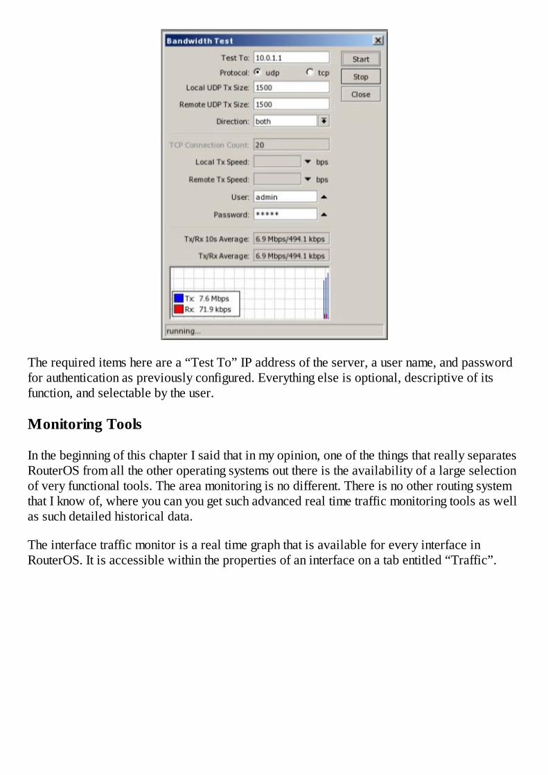
The required items here are a “Test To” IP address of the server, a user name, and passwordfor authentication as previously configured. Everything else is optional, descriptive of itsfunction, and selectable by the user.
Monitoring Tools
In the beginning of this chapter I said that in my opinion, one of the things that really separatesRouterOS from all the other operating systems out there is the availability of a large selectionof very functional tools. The area monitoring is no different. There is no other routing systemthat I know of, where you can you get such advanced real time traffic monitoring tools as wellas such detailed historical data.
The interface traffic monitor is a real time graph that is available for every interface inRouterOS. It is accessible within the properties of an interface on a tab entitled “Traffic”.

In the interface traffic monitor, traffic passing through the interface is measured and displayedgraphically using directional flow identifiers for Transmit (Tx) and Receive (Rx) rates aswell as a lower level display of packets per second. In addition, Tx and Rx errors aredisplayed for the interface thereby giving the technician a quick and simple view of the trafficpassing through the interface. The interface traffic monitor is found on all interfaces by rightclicking the interface in the Interfaces list, selecting Properties, and clicking the Traffic tab.
Torch
The operation of the Torch tool was described on page 115.
Example – Using Torch to Troubleshoot “Slow” Networks
This particular example is more of a story and application rather than a step-by-step guide asthe actual steps are simple, you just click the Tools menu and select Torch. This is a classicexample of how Torch and RouterOS can make the operation of a provider network so muchsimpler and give your technicians fingertip access to diagnostic power that the telecoms onlyhave at their highest level of IP network engineering.
The scenario is simple and common for an Internet service provider. A customer calls in andcomplains their Internet connection is “slow”. “Slow” is a relative term and really makes thepossibility of ending this call in a manner that is satisfactory to the customer a real challenge.In addition, it has been my experience that a service provider can give excellent service foryears and when there is one “hiccup”, regardless of the responsible party, the perception fromthe consumer is that “the service has always been terrible and has never worked right”.
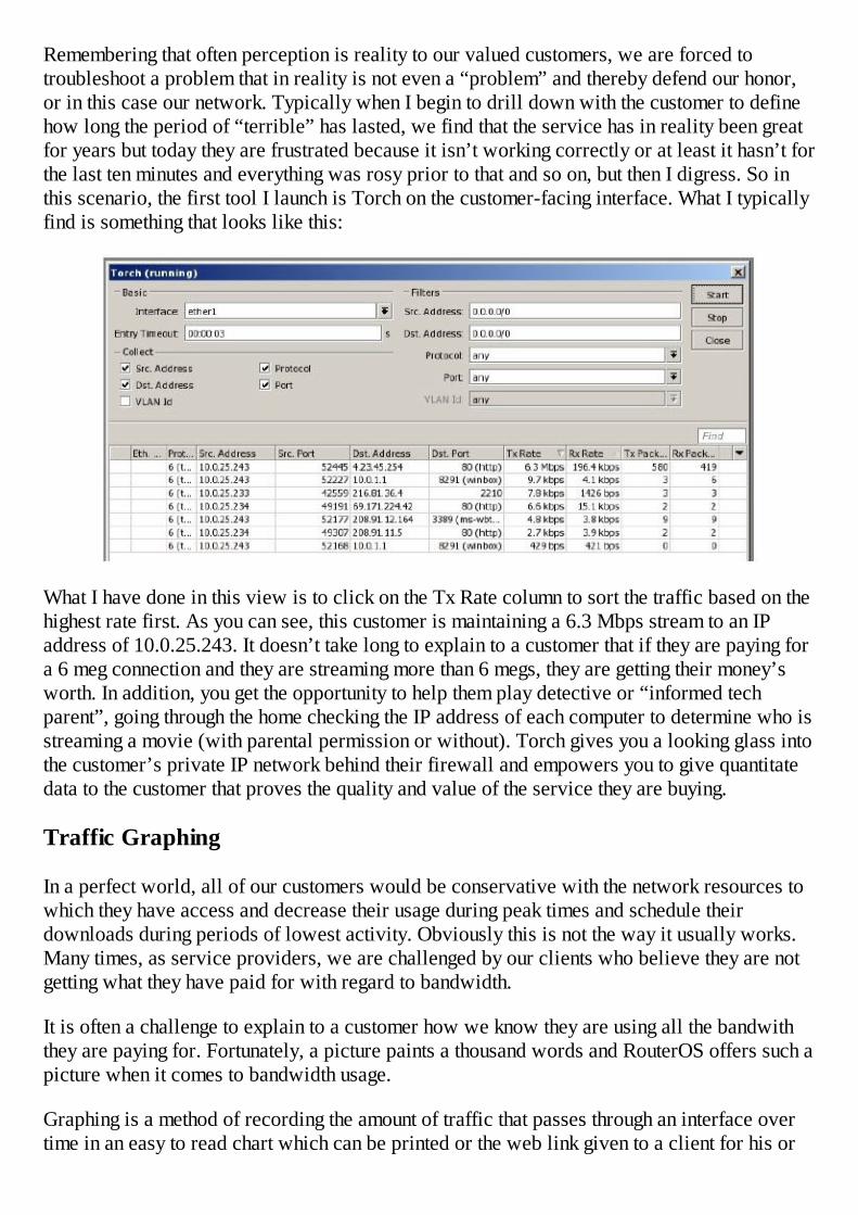
Remembering that often perception is reality to our valued customers, we are forced totroubleshoot a problem that in reality is not even a “problem” and thereby defend our honor,or in this case our network. Typically when I begin to drill down with the customer to definehow long the period of “terrible” has lasted, we find that the service has in reality been greatfor years but today they are frustrated because it isn’t working correctly or at least it hasn’t forthe last ten minutes and everything was rosy prior to that and so on, but then I digress. So inthis scenario, the first tool I launch is Torch on the customer-facing interface. What I typicallyfind is something that looks like this:
What I have done in this view is to click on the Tx Rate column to sort the traffic based on thehighest rate first. As you can see, this customer is maintaining a 6.3 Mbps stream to an IPaddress of 10.0.25.243. It doesn’t take long to explain to a customer that if they are paying fora 6 meg connection and they are streaming more than 6 megs, they are getting their money’sworth. In addition, you get the opportunity to help them play detective or “informed techparent”, going through the home checking the IP address of each computer to determine who isstreaming a movie (with parental permission or without). Torch gives you a looking glass intothe customer’s private IP network behind their firewall and empowers you to give quantitatedata to the customer that proves the quality and value of the service they are buying.
Traffic Graphing
In a perfect world, all of our customers would be conservative with the network resources towhich they have access and decrease their usage during peak times and schedule theirdownloads during periods of lowest activity. Obviously this is not the way it usually works.Many times, as service providers, we are challenged by our clients who believe they are notgetting what they have paid for with regard to bandwidth.
It is often a challenge to explain to a customer how we know they are using all the bandwiththey are paying for. Fortunately, a picture paints a thousand words and RouterOS offers such apicture when it comes to bandwidth usage.
Graphing is a method of recording the amount of traffic that passes through an interface overtime in an easy to read chart which can be printed or the web link given to a client for his or
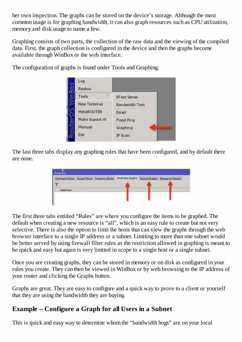
her own inspection. The graphs can be stored on the device’s storage. Although the mostcommon usage is for graphing bandwidth, it can also graph resources such as CPU utilization,memory and disk usage to name a few.
Graphing consists of two parts, the collection of the raw data and the viewing of the compileddata. First, the graph collection is configured in the device and then the graphs becomeavailable through WinBox or the web interface.
The configuration of graphs is found under Tools and Graphing.
The last three tabs display any graphing rules that have been configured, and by default thereare none.
The first three tabs entitled “Rules” are where you configure the items to be graphed. Thedefault when creating a new resource is “all", which is an easy rule to create but not veryselective. There is also the option to limit the hosts that can view the graphs through the webbrowser interface to a single IP address or a subnet. Limiting to more than one subnet wouldbe better served by using firewall filter rules as the restriction allowed in graphing is meant tobe quick and easy but again is very limited in scope to a single host or a single subnet.
Once you are creating graphs, they can be stored in memory or on disk as configured in yourrules you create. They can then be viewed in WinBox or by web browsing to the IP address ofyour router and clicking the Graphs button.
Graphs are great. They are easy to configure and a quick way to prove to a client or yourselfthat they are using the bandwidth they are buying.
Example – Configure a Graph for all Users in a Subnet
This is quick and easy way to determine whom the “bandwidth hogs” are on your local

network. It involves both Queues and Graphs, however, the purposes of the queues here is notto limit bandwidth but merely to provide a mechanism to measure bandwidth.
The fastest way to create the queues is to use an Excel spreadsheet with its ability to fill rowsof cells with consecutive numbers easily to create a script, and then pasting or importing thescript into RouterOS. If you aren’t comfortable with this method, you can create the queuesmanually.
1. Create a simple queue for each host IP address in your local subnet. In the case of a/24, that is 253 queues assuming you want to log bandwidth to every single oneexcluding the default gateway address.
2. Do not apply a bandwidth limit in the queue. Instead, simply create a queue with atarget address of each IP address. Each queue should look like this:
3. In Tools Graphing, create a new rule to graph all queues like this:
4. Now, when I web browse to the router IP address I can click the Graphs button.
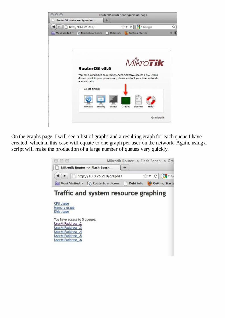
On the graphs page, I will see a list of graphs and a resulting graph for each queue I havecreated, which in this case will equate to one graph per user on the network. Again, using ascript will make the production of a large number of queues very quickly.

This method is quick and easy to configure and provides a lot of valuable data. For the htmlsavvy user, it would be quite easy to create a single html web page that included (the<iframe> tag would be a good method to do this) one graph for each user on the network allon one page for quick and easy analysis.
SNMP – Simple Network Management Protocol
SNMP is a standard Internet protocol to provide management of devices on IP networks. In itssimplest terms, SNMP provides a way to get useful information about the performance of adevice and then use that in a meaningful way like producing graphs and charts and recordingperformance over a historical period.
In RouterOS, it is found through the IP button and then selecting SNMP. There, by default, youwill see an SNMP string that is configured with the name “public”. For security, you shouldremove this entry and configure your own SNMP community string that is a bit tougher forsomeone to guess and possibly use in some way to exploit your device. Although not common,a good system administrator is always on the watch for ways hackers can exploit his or hernetwork.
By default, SNMP is turned off and can be turned on by clicking the SNMP Settings button andenabling it. Other information can be added as desired and may be used for certain programsthat read SNMP information.
If you are using any programs to poll SNMP data from your routers then by all meansconfigure it appropriately, otherwise there is no need to turn it on or make any changes.


Chapter 12 – Local Area Networks
The LAN or the Local Area Network is a technical term for the network topology that is usedin our home, our office, or the campus on which we operate. The attributes that differentiatethe LAN from its neighbor the WAN or Wide Area Network are typically higher throughputrates, closer proximity of hosts and the sharing of a common broadcast domain. A broadcastdomain is a segment of a computer network where all hosts can communicate directly witheach other by broadcast on the data link layer or Layer 2 of the OSI model. Broadcastdomains are separated by Layer 3 devices such as routers or Layer 3 switches. In summary, iftwo computers are connected to the same Layer 2 switch, they are on the same broadcastdomain and they are certainly on the same LAN.
Thus far we have been working under the assumption that you have at least a basicunderstanding of the OSI model. To ensure we are using terms and phrases you are familiarwith, I would like to offer some foundation.
Briefly stated, the OSI model defines the framework of our modern IP networks. It is based ona layered topology with seven distinct layers. In this book we are only concerned with thefirst three layers.
Layer 1 – The physical layer. This is the cable, the fiber, or the wireless media weuse to connect two or more hosts together. It is not intelligent but nevertheless it isnecessary.
Layer 2 – The data link layer. In this layer, things become slightly more abstract,however there is still some firm ground so let me explain. Every network device comesfrom its manufacturer with a hard coded “serial number” that identifies it to otherdevices. This number is called the MAC address or Media Access Control address.The format is something like “00:0C:42:CE:05:1D”. Layer 2 network switchesunderstand MAC addresses and not much more. Their job is to pass packets aroundbased on MAC addresses and because their scope of focus is limited to the MACaddress, they can do that very quickly and efficiently.
Layer 3 – The network layer. Now we have reached the heart of an IP network, thenetwork layer. This layer is where routers operate and where IP addresses live. Thenetwork layer is even more abstract and dynamic than the data link layer because IPaddresses can be assigned to interfaces, changed, or moved to other interfaces. Thismakes it the most dynamic of the first three layers.
ARP
You can see from this brief description that each of these layers is very unique, distinct, andseparate from one another, but to hold them together as a system we need some “glue”. ARPor Address Resolution Protocol is the “glue” that holds together two layers of the OSI model,Layer 2 and Layer 3. The ARP protocol creates a table on the router, which is nothing morethan a lookup table, to tie together the MAC address of other hosts on the LAN with theirrespective IP addresses.
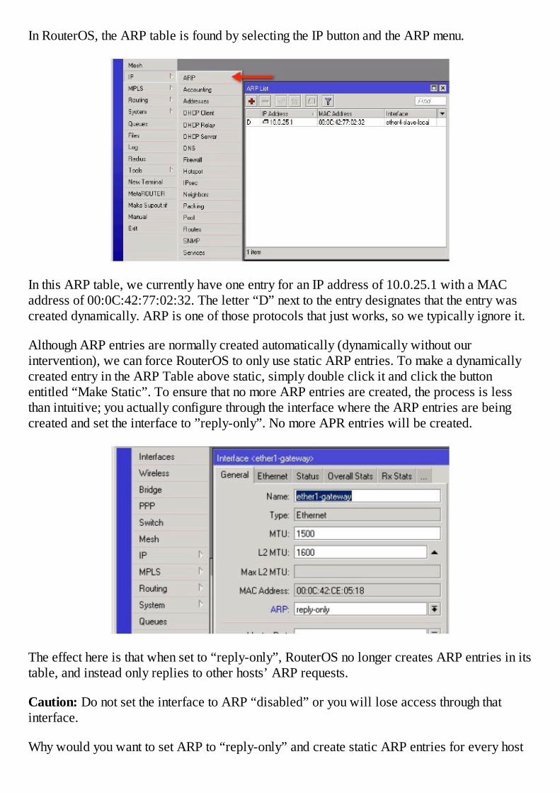
In RouterOS, the ARP table is found by selecting the IP button and the ARP menu.
In this ARP table, we currently have one entry for an IP address of 10.0.25.1 with a MACaddress of 00:0C:42:77:02:32. The letter “D” next to the entry designates that the entry wascreated dynamically. ARP is one of those protocols that just works, so we typically ignore it.
Although ARP entries are normally created automatically (dynamically without ourintervention), we can force RouterOS to only use static ARP entries. To make a dynamicallycreated entry in the ARP Table above static, simply double click it and click the buttonentitled “Make Static”. To ensure that no more ARP entries are created, the process is lessthan intuitive; you actually configure through the interface where the ARP entries are beingcreated and set the interface to ”reply-only”. No more APR entries will be created.
The effect here is that when set to “reply-only”, RouterOS no longer creates ARP entries in itstable, and instead only replies to other hosts’ ARP requests.
Caution: Do not set the interface to ARP “disabled” or you will lose access through thatinterface.
Why would you want to set ARP to “reply-only” and create static ARP entries for every host

on your network? Did you read the second part of that question “create static ARP entries forevery host on your network”? That is important because if you do not create static ARPentries for every host on your network, this router will not be able to communicate with them.ARP is the glue that binds Layer 2 to Layer 3 so without it, communication stops. The answerto the question is that using static ARP entries is not a common thing, however, if you want toincrease the level of security in your LAN, then static ARP will do that. By that, I mean, if anew host is brought onto the LAN, the existing hosts will not have static ARP entries for thenew host so they will not communicate with it and now the LAN is arguably more secure.
Example – Create a LAN that Requires Static ARP
This example is really meant to be an application that teaches a concept, not a recommendedpractice. To switch your network to static ARP, first you must create a static ARP entry forevery host on your LAN on every host on your LAN. This could be a big task but RouterOSmakes it easy.
1. Using the IP Scan tool, scan your LAN subnet. This will cause ARP to create an ARPentry for every host it discovers. Remember that ARP entries expire and flush aftersome period of time so this has to be done quickly.
The tool only requires your subnet be entered and click Start.

2. ARP entries will be created for each host that replies to the IP Scan probe.
3. Once the scan has completed, click IP button in WinBox and select ARP. In the ARPlist, click the top entry, hold the shift key and click the bottom entry in the list to selecteverything in the ARP table, right click and select “Make Static”.
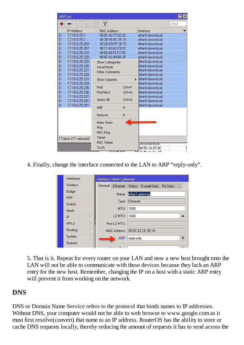
4. Finally, change the interface connected to the LAN to ARP “reply-only”.
5. That is it. Repeat for every router on your LAN and now a new host brought onto theLAN will not be able to communicate with these devices because they lack an ARPentry for the new host. Remember, changing the IP on a host with a static ARP entrywill prevent it from working on the network.
DNS
DNS or Domain Name Service refers to the protocol that binds names to IP addresses.Without DNS, your computer would not be able to web browse to www.google.com as itmust first resolve(convert) that name to an IP address. RouterOS has the ability to store orcache DNS requests locally, thereby reducing the amount of requests it has to send across the
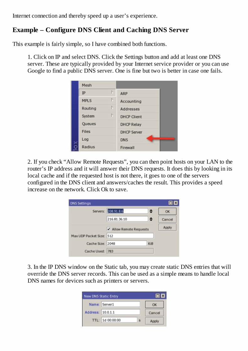
Internet connection and thereby speed up a user’s experience.
Example – Configure DNS Client and Caching DNS Server
This example is fairly simple, so I have combined both functions.
1. Click on IP and select DNS. Click the Settings button and add at least one DNSserver. These are typically provided by your Internet service provider or you can useGoogle to find a public DNS server. One is fine but two is better in case one fails.
2. If you check “Allow Remote Requests”, you can then point hosts on your LAN to therouter’s IP address and it will answer their DNS requests. It does this by looking in itslocal cache and if the requested host is not there, it goes to one of the serversconfigured in the DNS client and answers/caches the result. This provides a speedincrease on the network. Click Ok to save.
3. In the IP DNS window on the Static tab, you may create static DNS entries that willoverride the DNS server records. This can be used as a simple means to handle localDNS names for devices such as printers or servers.

DHCP – Dynamic Host Configuration Protocol
DHCP is another one of those protocols we often take for granted, that is unless you rememberwhen everything was statically addressed. DHCP takes the guesswork out of IP addressallocation.
The DHCP protocol comprises two parts. These two parts are:
1. A server which listens for requests by DHCP clients, responds with an IP address,DNS server, and a default gateway.
2. A client that makes the DHCP request.
In addition, other information may be sent as options or configurations can be made on theDHCP server in response to the client request.
DHCP Client
The DHCP client is simple to set up. It merely involves telling the router the interface onwhich you want to request a DHCP address. In addition, you can request a DNS server anddefault gateway, and in most cases you want to receive those configuration pieces as well asan IP address.
Example – Add a DHCP Client
The goal with this exercise is to get an IP address dynamically on the router assuming there isan active DHCP server on the LAN.
1. From the IP menu, select DHCP Client.
2. Click the plus sign on the New DHCP Client window and select the interface onwhich you want to receive the IP address and click OK.
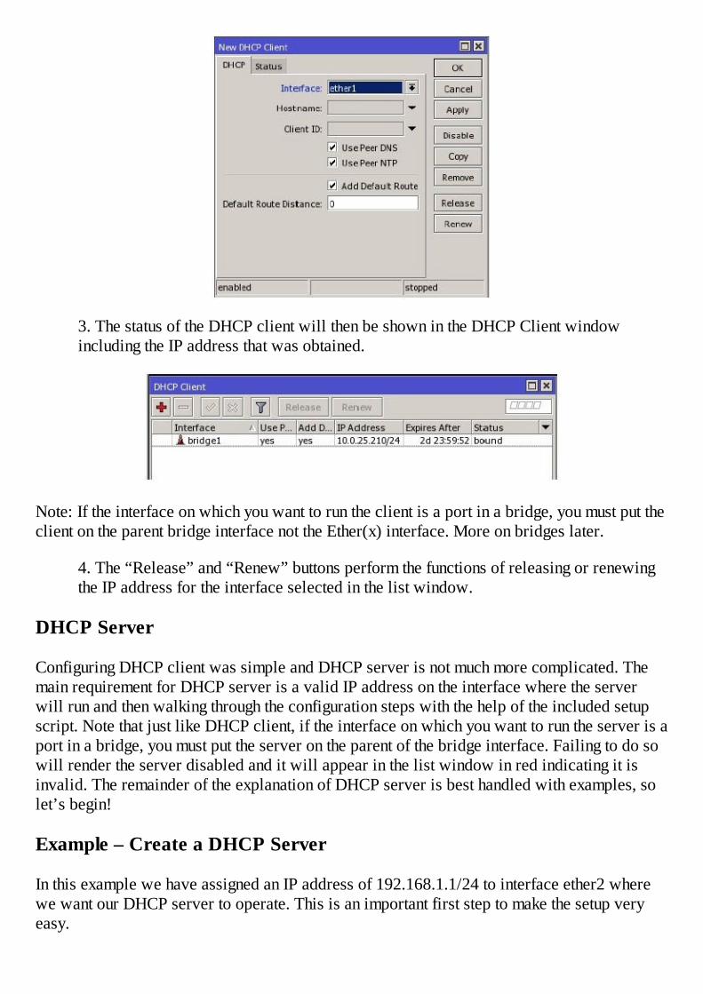
3. The status of the DHCP client will then be shown in the DHCP Client windowincluding the IP address that was obtained.
Note: If the interface on which you want to run the client is a port in a bridge, you must put theclient on the parent bridge interface not the Ether(x) interface. More on bridges later.
4. The “Release” and “Renew” buttons perform the functions of releasing or renewingthe IP address for the interface selected in the list window.
DHCP Server
Configuring DHCP client was simple and DHCP server is not much more complicated. Themain requirement for DHCP server is a valid IP address on the interface where the serverwill run and then walking through the configuration steps with the help of the included setupscript. Note that just like DHCP client, if the interface on which you want to run the server is aport in a bridge, you must put the server on the parent of the bridge interface. Failing to do sowill render the server disabled and it will appear in the list window in red indicating it isinvalid. The remainder of the explanation of DHCP server is best handled with examples, solet’s begin!
Example – Create a DHCP Server
In this example we have assigned an IP address of 192.168.1.1/24 to interface ether2 wherewe want our DHCP server to operate. This is an important first step to make the setup veryeasy.

1. From the IP menu, select DHCP Server.
2. Click the DHCP Setup button to begin the configuration script. The first selection isthe interface on which you want DHCP to operate.
3. From this point forward you can typically accept the defaults, or make adjustments asrequired. The first window like this is the network address.
4. Next is the default gateway, typically the IP you added on the interface previously.
5. Next is the pool of addresses that will be created. If you want to exclude certainranges of addresses from the DHCP pool, now is your opportunity.

6. Next is the IP address of the DNS server(s) you want to give to your clientsconnecting to this interface. Again, make adjustments here as you wish but rememberyou must give clients at least one DNS server or the setup script will fail. If you wantyour clients to use your caching DNS server, then use the IP of your local interface. Thelogic is that we only want our clients to use our router for DNS since we are cachingDNS requests. The router will then either answer from cache or go to its own DNSserver to resolve the address.
7. Next is the lease time and in most cases 3 days is fine. In situations where there is ahigh turnover of clients such as a public venue or a hotel, you may wish to make thistime much lower to prevent exhausting your pool of IP addresses. An IP can not bereused until the lease expires, even if the client leaves the network, so shorter leasetimes are better for networks with high turnovers.
8. DHCP server is now complete.
9. Once you have completed the setup script, any changes you would like to make canbe done under the DHCP tab or the Networks tab.

10. Any changes to the IP pool can be done under IP Pool.
Example – DHCP Static Leases
In many cases it is desired that a host always receive the same IP address. For instance, youmay have a computer on your network that you wish to access via remote desktop. In this case,static leases will ensure a host always receives the same IP address.
In the Leases window, find the lease you want to make static. Double click it to change theproperties and click the button “Make Static”.
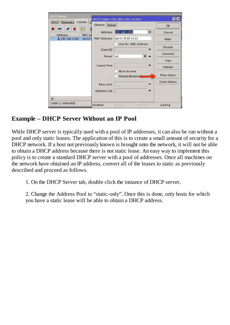
Example – DHCP Server Without an IP Pool
While DHCP server is typically used with a pool of IP addresses, it can also be run without apool and only static leases. The application of this is to create a small amount of security for aDHCP network. If a host not previously known is brought onto the network, it will not be ableto obtain a DHCP address because there is not static lease. An easy way to implement thispolicy is to create a standard DHCP server with a pool of addresses. Once all machines onthe network have obtained an IP address, convert all of the leases to static as previouslydescribed and proceed as follows.
1. On the DHCP Server tab, double click the instance of DHCP server.
2. Change the Address Pool to “static-only”. Once this is done, only hosts for whichyou have a static lease will be able to obtain a DHCP address.
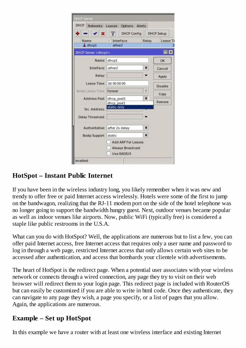
HotSpot – Instant Public Internet
If you have been in the wireless industry long, you likely remember when it was new andtrendy to offer free or paid Internet access wirelessly. Hotels were some of the first to jumpon the bandwagon, realizing that the RJ-11 modem port on the side of the hotel telephone wasno longer going to support the bandwidth hungry guest. Next, outdoor venues became popularas well as indoor venues like airports. Now, public WiFi (typically free) is considered astaple like public restrooms in the U.S.A.
What can you do with HotSpot? Well, the applications are numerous but to list a few, you canoffer paid Internet access, free Internet access that requires only a user name and password tolog in through a web page, restricted Internet access that only allows certain web sites to beaccessed after authentication, and access that bombards your clientele with advertisements.
The heart of HotSpot is the redirect page. When a potential user associates with your wirelessnetwork or connects through a wired connection, any page they try to visit on their webbrowser will redirect them to your login page. This redirect page is included with RouterOSbut can easily be customized if you are able to write in html code. Once they authenticate, theycan navigate to any page they wish, a page you specify, or a list of pages that you allow.Again, the applications are numerous.
Example – Set up HotSpot
In this example we have a router with at least one wireless interface and existing Internet

access. Our goal is to create a default HotSpot on the wireless interface. Setting up HotSpot isvery similar to setting up DHCP server, it is easily done through a setup script.
1. In WinBox, click the IP button and select HotSpot. Click the HotSpot Setup button tobegin. For your first HotSpot, I recommend accepting the defaults for everything; it ismuch easier that way.
2. Click the HotSpot Setup button.
3. Select the interface where HotSpot will run, in this case, our wireless interface.
4. Next select the IP address for the interface. We are using the default IP address here.

5. Select the pool of addresses to be issued, the defaults are fine.
6. This is an advanced option for those wanting SSL encrypted logins, the option“none” is fine for our example.
7. This can be dangerous so I recommend leaving it at the default of all zero’s whichmeans do not configure a default SMTP server. If you configure this option, all emailfrom your HotSpot network will be redirected to your email server. Unless you want tobe a spammer, leave it alone.
8. DNS servers are required, so be sure to set them here.
9. This can be anything you want users to see in their web browser on the address lineafter the redirect. I recommend using a standard URL format. It does not have to be a
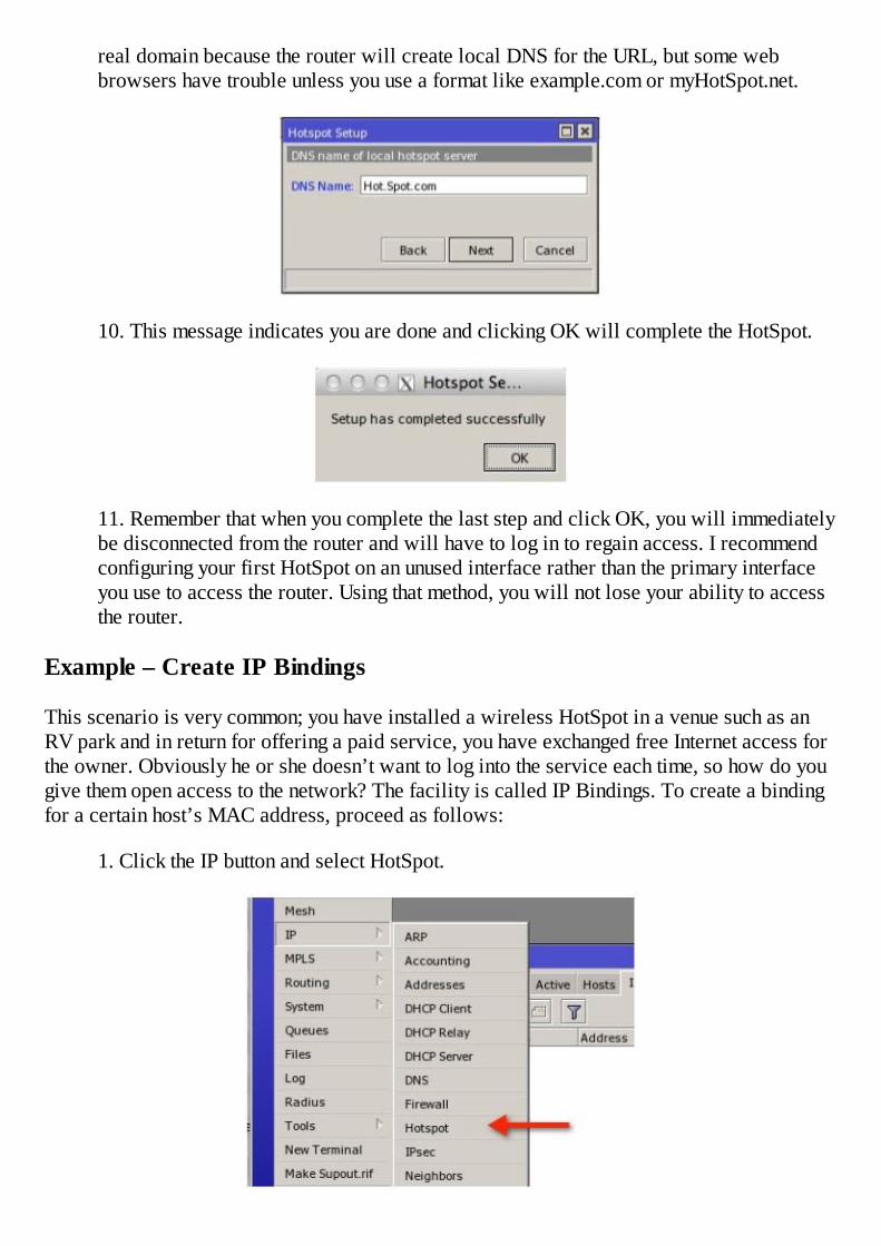
real domain because the router will create local DNS for the URL, but some webbrowsers have trouble unless you use a format like example.com or myHotSpot.net.
10. This message indicates you are done and clicking OK will complete the HotSpot.
11. Remember that when you complete the last step and click OK, you will immediatelybe disconnected from the router and will have to log in to regain access. I recommendconfiguring your first HotSpot on an unused interface rather than the primary interfaceyou use to access the router. Using that method, you will not lose your ability to accessthe router.
Example – Create IP Bindings
This scenario is very common; you have installed a wireless HotSpot in a venue such as anRV park and in return for offering a paid service, you have exchanged free Internet access forthe owner. Obviously he or she doesn’t want to log into the service each time, so how do yougive them open access to the network? The facility is called IP Bindings. To create a bindingfor a certain host’s MAC address, proceed as follows:
1. Click the IP button and select HotSpot.

2. On the Bindings tab, click the plus sign to create a new binding.
3. Enter the MAC address of the host to be given open access and set the Type to“bypassed”.
Example – Create additional Users
During the running of the IP HotSpot setup, you were prompted to create a user or set thepassword for the default user to “admin”. It is important to note that the HotSpot user “admin”is not the same admin that can log into the router and configure it. They are two differentdatabases and two different users. If you need to create additional HotSpot users, the processis simple.
1. Click the IP button and select HotSpot.
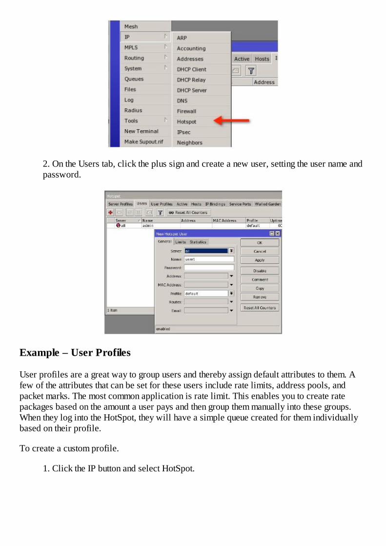
2. On the Users tab, click the plus sign and create a new user, setting the user name andpassword.
Example – User Profiles
User profiles are a great way to group users and thereby assign default attributes to them. Afew of the attributes that can be set for these users include rate limits, address pools, andpacket marks. The most common application is rate limit. This enables you to create ratepackages based on the amount a user pays and then group them manually into these groups.When they log into the HotSpot, they will have a simple queue created for them individuallybased on their profile.
To create a custom profile.
1. Click the IP button and select HotSpot.
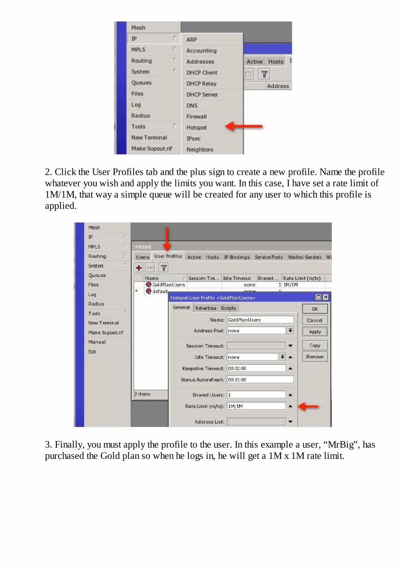
2. Click the User Profiles tab and the plus sign to create a new profile. Name the profilewhatever you wish and apply the limits you want. In this case, I have set a rate limit of1M/1M, that way a simple queue will be created for any user to which this profile isapplied.
3. Finally, you must apply the profile to the user. In this example a user, “MrBig”, haspurchased the Gold plan so when he logs in, he will get a 1M x 1M rate limit.
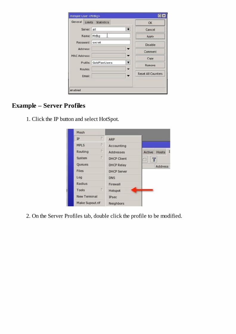
Example – Server Profiles
1. Click the IP button and select HotSpot.
2. On the Server Profiles tab, double click the profile to be modified.
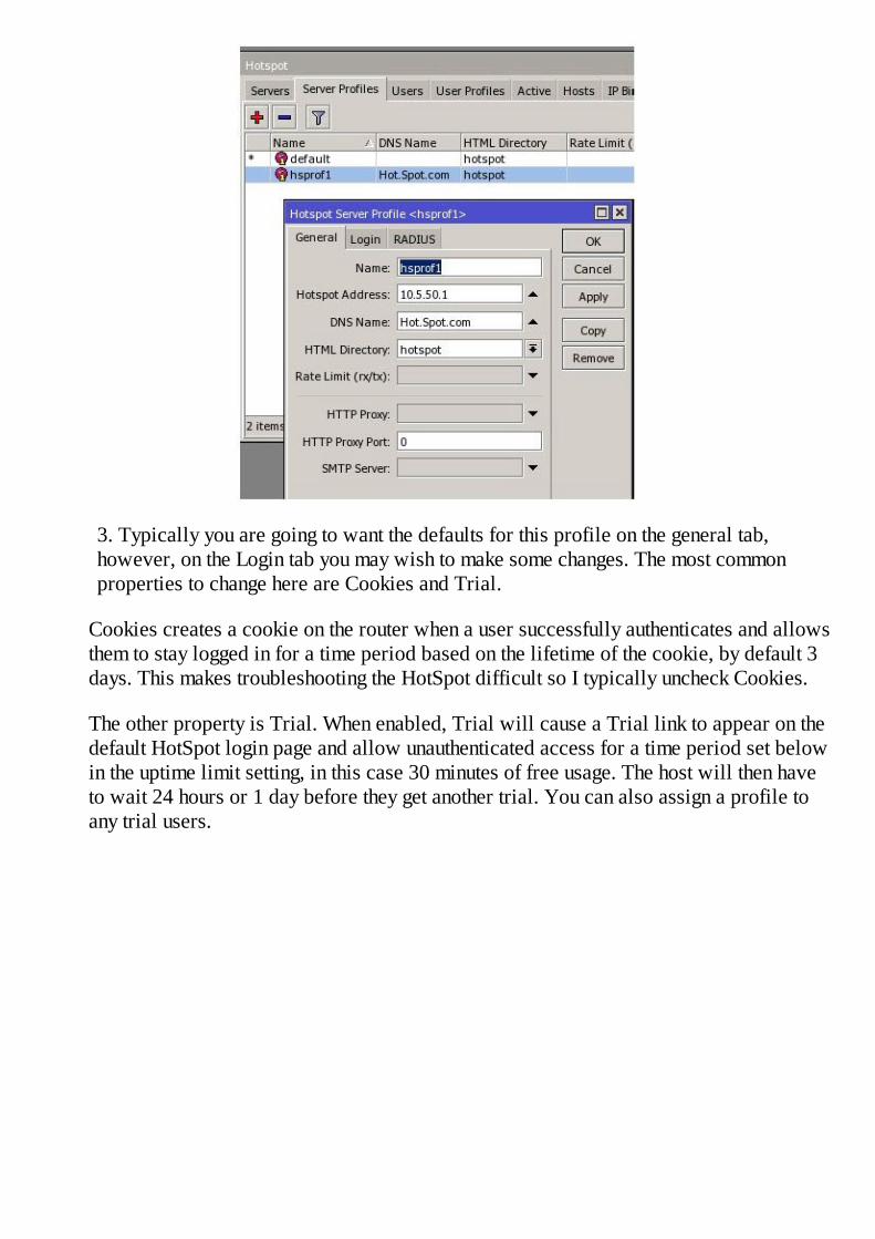
3. Typically you are going to want the defaults for this profile on the general tab,however, on the Login tab you may wish to make some changes. The most commonproperties to change here are Cookies and Trial.
Cookies creates a cookie on the router when a user successfully authenticates and allowsthem to stay logged in for a time period based on the lifetime of the cookie, by default 3days. This makes troubleshooting the HotSpot difficult so I typically uncheck Cookies.
The other property is Trial. When enabled, Trial will cause a Trial link to appear on thedefault HotSpot login page and allow unauthenticated access for a time period set belowin the uptime limit setting, in this case 30 minutes of free usage. The host will then haveto wait 24 hours or 1 day before they get another trial. You can also assign a profile toany trial users.
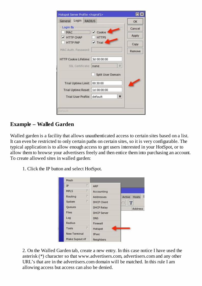
Example – Walled Garden
Walled garden is a facility that allows unauthenticated access to certain sites based on a list.It can even be restricted to only certain paths on certain sites, so it is very configurable. Thetypical application is to allow enough access to get users interested in your HotSpot, or toallow them to browse your advertisers freely and then entice them into purchasing an account.To create allowed sites in walled garden:
1. Click the IP button and select HotSpot.
2. On the Walled Garden tab, create a new entry. In this case notice I have used theasterisk (*) character so that www.advertisers.com, advertisers.com and any otherURL’s that are in the advertisers.com domain will be matched. In this rule I amallowing access but access can also be denied.
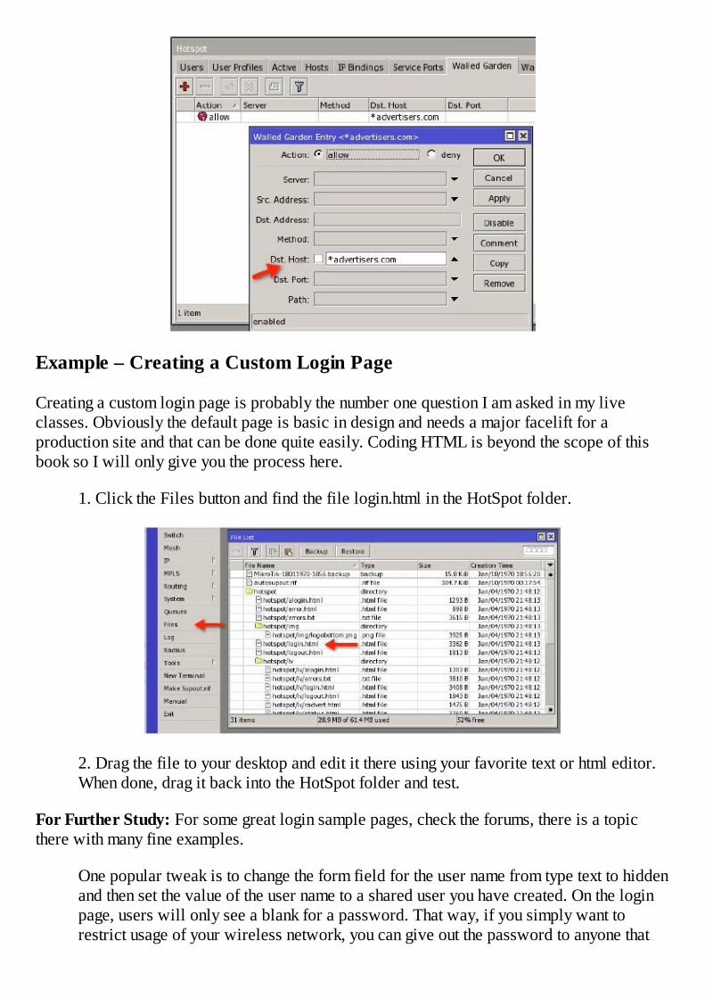
Example – Creating a Custom Login Page
Creating a custom login page is probably the number one question I am asked in my liveclasses. Obviously the default page is basic in design and needs a major facelift for aproduction site and that can be done quite easily. Coding HTML is beyond the scope of thisbook so I will only give you the process here.
1. Click the Files button and find the file login.html in the HotSpot folder.
2. Drag the file to your desktop and edit it there using your favorite text or html editor.When done, drag it back into the HotSpot folder and test.
For Further Study: For some great login sample pages, check the forums, there is a topicthere with many fine examples.
One popular tweak is to change the form field for the user name from type text to hiddenand then set the value of the user name to a shared user you have created. On the loginpage, users will only see a blank for a password. That way, if you simply want torestrict usage of your wireless network, you can give out the password to anyone that

wants to use your wireless and not have to deal with the added complication of dealingwith user names too. In login.html, look for the login form section:
Change the text identified by the arrows to this:
Also note you will need to create a user profile for the shared user and set the SharedUsers setting to a higher number than one, otherwise only one person can log into yourHotSpot using this method.
When a user loads the login page, they will only see a password blank to log in. You willobviously want to customize the page further but that is beyond the scope of this book.
Web Proxy
Web proxy is a utility included with RouterOS that enables your router to act as a web cacheand HTTP firewall. Specifically, when a user tries to visit a web page, the proxy receives therequest, gets the page from the source and returns it to the user’s browser. If the proxy haspreviously retrieved the page and stored it to memory or disk, it will deliver it from the cacherather than retrieve it from the actual web host. This process can significantly speed up auser’s web experience and reduce overall utilization of the Internet connection. HTTPs or

secure web pages cannot be cached. A cached copy of your bank statement would not behelpful.
Some caveats need to be stated here for the safety and proper operation of web proxy on yournetwork. First, web proxy can be easily misused and exploited by hackers so it isimportant to only allow access to certain hosts on your network using firewall rules. Iwill demonstrate those rules in the example to follow. Also, simply configuring web proxy isnot enough to put it in place in your network; you will need some NAT rules to send HTTPtraffic to the proxy.
Example – Configuring a Transparent Web Proxy
This configuration is referred to as “transparent”, because it requires no configuration byusers on the network. In this scenario NAT rules intercept all HTTP traffic and send it to theproxy.
1. First, we configure the proxy itself. Click the IP button and select Web Proxy.
(Menu is compressed in this view)
2. Check the box “Enabled” and the defaults are fine for everything else. You likely donot want to cache on disk unless your board has an external drive. The RouterBOARDitself has limited onboard storage and the constant writes to the storage may shorten itslife.

3. Next, we need a NAT rule to send all TCP port 80 (web traffic) to the proxy. This isdone under IP Firewall NAT.
The action for the NAT rule is redirect, which as you may remember means intercept thetraffic and process it on the router.
4. Finally, we need a firewall rule (actually two) to prevent unauthorized access to our
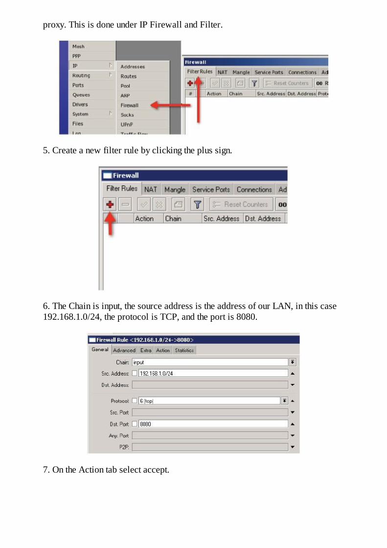
proxy. This is done under IP Firewall and Filter.
5. Create a new filter rule by clicking the plus sign.
6. The Chain is input, the source address is the address of our LAN, in this case192.168.1.0/24, the protocol is TCP, and the port is 8080.
7. On the Action tab select accept.

8. Next we need a rule to drop all other traffic to our proxy. Again, the Chain is input,the protocol is TCP, and the port is 8080.
9. On the Action tab select drop.
The proxy is now intercepting all port 80 requests, and proxying them. In addition, thefirewall is allowing access to the proxy from the LAN but dropping proxy traffic fromall other sources.
Example – HTTP Firewall, Allowing or Blocking Certain Sites
With the web proxy in operation, now we can use the full power of this feature to allow, deny,or redirect certain sites. The Access rules are used for this purpose and work on an “if, then”principal, just like firewall rules. In this example we will allow access to www.mikrotik.comand block all other sites.

1. With a properly configured and working web proxy as detailed in the previousexample, click IP and select Web Proxy. Click the plus sign to create a new rule.
2. The Dst. Host will be the site you want to allow, in this case *mikrotik.com. We usedthe asterisk here so that www.mikrotik.com or just mikrotik.com would match the rule.Then click Ok.

3. Next we need a rule to block access to all other sites. Remember, rule order isalways important. The new rule is created using the plus sign, and the only thingchanged is the Action of “deny”.
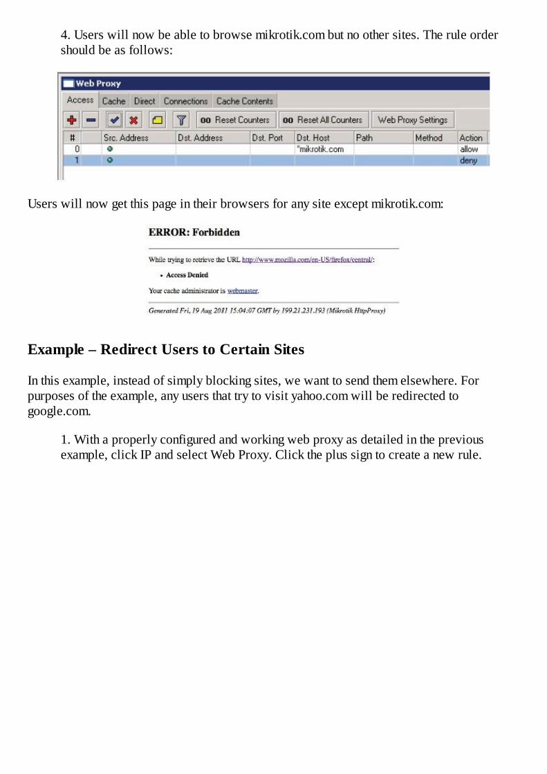
4. Users will now be able to browse mikrotik.com but no other sites. The rule ordershould be as follows:
Users will now get this page in their browsers for any site except mikrotik.com:
Example – Redirect Users to Certain Sites
In this example, instead of simply blocking sites, we want to send them elsewhere. Forpurposes of the example, any users that try to visit yahoo.com will be redirected togoogle.com.
1. With a properly configured and working web proxy as detailed in the previousexample, click IP and select Web Proxy. Click the plus sign to create a new rule.

2. The Dst. Host will be the site you want to redirect, in this case *yahoo.com. In theaction, select deny as before but now we add a “redirect to” address of google.com.The net result is that any users that browse to yahoo.com will instead get google.com.
3. Next we need a rule to block access to all other sites. Remember, rule order isalways important. The new rule is created using the plus sign, and the only thingchanged is the Action “deny”.
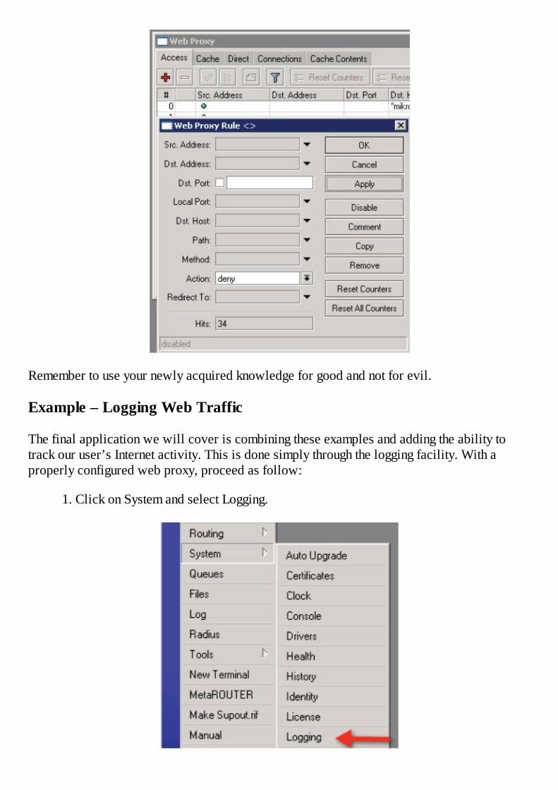
Remember to use your newly acquired knowledge for good and not for evil.
Example – Logging Web Traffic
The final application we will cover is combining these examples and adding the ability totrack our user’s Internet activity. This is done simply through the logging facility. With aproperly configured web proxy, proceed as follow:
1. Click on System and select Logging.

2. Create a new logging rule for the topic- web-proxy. Then click the down arrow tocreate another row and then click the “not” box (!) and select debug. Combining loggingrules like this modifies the rule such that we will log web proxy requests but removethe debug information to make them more readable. You can optionally add a prefix, atext string that will be appended to the beginning of each line in order to make themeasier to identify in the logs. In this case I have entered “LOGGING->”.
3. Logging to memory is not a good option here except for purposes of this example.Instead, I suggest logging remotely to a syslog server.
As you can see, web proxy can not only improve network performance and reduce Internetusage but can also create an HTTP firewall or create a permanent log of sites visited.
Example – Logging to a Remote Syslog Server
There are many syslog servers available free of charge for a diverse variety of platforms.Syslog is a server daemon (a Linux term for a service or process) that listens for loggingstreams from remote devices and writes them to a central log. This is a scalable way to designa network because of the ability to centrally monitor the logs of all devices and store manydays worth of logs with central archiving. The Dude, MikroTik’s free monitoring solution,comes complete with a syslog server. To enable remote logging to a syslog server, proceed asfollows.
1. Click on the System button and select logging.
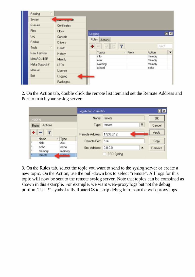
2. On the Action tab, double click the remote list item and set the Remote Address andPort to match your syslog server.
3. On the Rules tab, select the topic you want to send to the syslog server or create anew topic. On the Action, use the pull-down box to select “remote”. All logs for thistopic will now be sent to the remote syslog server. Note that topics can be combined asshown in this example. For example, we want web-proxy logs but not the debugportion. The “!” symbol tells RouterOS to strip debug info from the web-proxy logs.

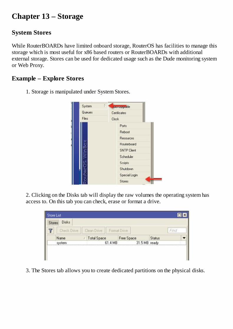
Chapter 13 – Storage
System Stores
While RouterBOARDs have limited onboard storage, RouterOS has facilities to manage thisstorage which is most useful for x86 based routers or RouterBOARDs with additionalexternal storage. Stores can be used for dedicated usage such as the Dude monitoring systemor Web Proxy.
Example – Explore Stores
1. Storage is manipulated under System Stores.
2. Clicking on the Disks tab will display the raw volumes the operating system hasaccess to. On this tab you can check, erase or format a drive.
3. The Stores tab allows you to create dedicated partitions on the physical disks.
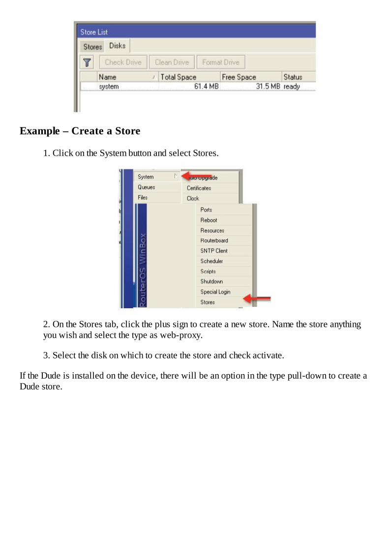
Example – Create a Store
1. Click on the System button and select Stores.
2. On the Stores tab, click the plus sign to create a new store. Name the store anythingyou wish and select the type as web-proxy.
3. Select the disk on which to create the store and check activate.
If the Dude is installed on the device, there will be an option in the type pull-down to create aDude store.


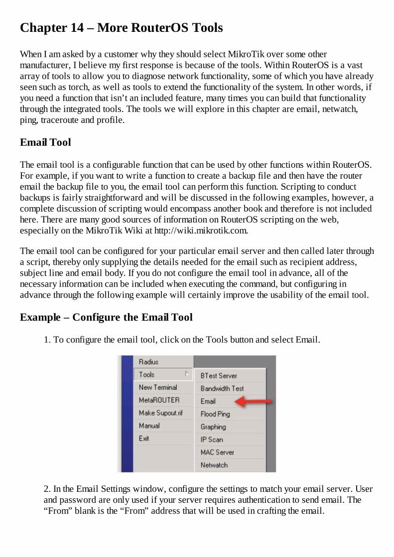
Chapter 14 – More RouterOS Tools
When I am asked by a customer why they should select MikroTik over some othermanufacturer, I believe my first response is because of the tools. Within RouterOS is a vastarray of tools to allow you to diagnose network functionality, some of which you have alreadyseen such as torch, as well as tools to extend the functionality of the system. In other words, ifyou need a function that isn’t an included feature, many times you can build that functionalitythrough the integrated tools. The tools we will explore in this chapter are email, netwatch,ping, traceroute and profile.
Email Tool
The email tool is a configurable function that can be used by other functions within RouterOS.For example, if you want to write a function to create a backup file and then have the routeremail the backup file to you, the email tool can perform this function. Scripting to conductbackups is fairly straightforward and will be discussed in the following examples, however, acomplete discussion of scripting would encompass another book and therefore is not includedhere. There are many good sources of information on RouterOS scripting on the web,especially on the MikroTik Wiki at http://wiki.mikrotik.com.
The email tool can be configured for your particular email server and then called later througha script, thereby only supplying the details needed for the email such as recipient address,subject line and email body. If you do not configure the email tool in advance, all of thenecessary information can be included when executing the command, but configuring inadvance through the following example will certainly improve the usability of the email tool.
Example – Configure the Email Tool
1. To configure the email tool, click on the Tools button and select Email.
2. In the Email Settings window, configure the settings to match your email server. Userand password are only used if your server requires authentication to send email. The“From” blank is the “From” address that will be used in crafting the email.
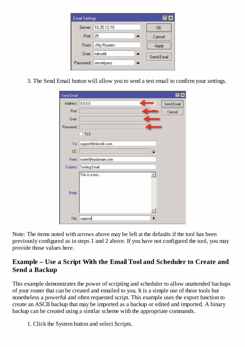
3. The Send Email button will allow you to send a test email to confirm your settings.
Note: The items noted with arrows above may be left at the defaults if the tool has beenpreviously configured as in steps 1 and 2 above. If you have not configured the tool, you mayprovide those values here.
Example – Use a Script With the Email Tool and Scheduler to Create andSend a Backup
This example demonstrates the power of scripting and scheduler to allow unattended backupsof your router that can be created and emailed to you. It is a simple use of these tools butnonetheless a powerful and often requested script. This example uses the export function tocreate an ASCII backup that may be imported as a backup or edited and imported. A binarybackup can be created using a similar scheme with the appropriate commands.
1. Click the System button and select Scripts.
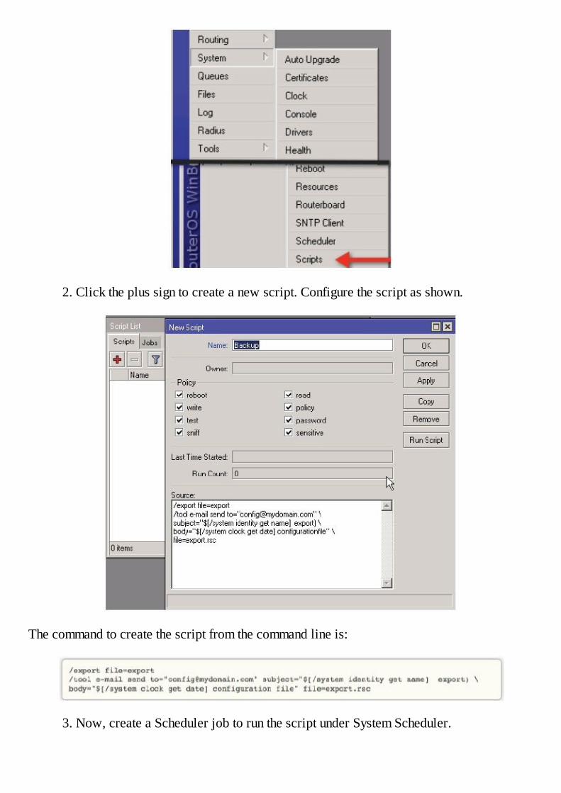
2. Click the plus sign to create a new script. Configure the script as shown.
The command to create the script from the command line is:
3. Now, create a Scheduler job to run the script under System Scheduler.

4. Click the plus sign and create a new scheduler job for our Backup script.
In this scheduler job, our backup script will run every day at 1:00 am and email the export fileto us. Scripts are great for extending the features of RouterOS. Almost any command can bescripted to run at a predetermined time and thereby allow unattended functions that make thissystem really powerful. The “On Event” property can be a series of RouterOS commands likelines from a script or the name of a stored script file.
Netwatch
The purpose of Netwatch is to execute a command if a host IP address is no longer reachableby ping. Upon ping timeout, a script can be executed for “Down” and when the host respondsagain, another script can be executed for “Up”. There are many uses for Netwatch and the

possibilities are endless.
Example – Reboot the Router Using Netwatch
RouterOS is extremely stable. I have many times seen router uptimes of over a year, so thechance of a router needing a reboot like a Windows based PC is really low. However, forpurposes of an example, here’s a way to reboot the router if it is no longer able to ping theInternet. The command executed by Netwatch is entirely up to you. Again, this is only anexample.
1. Click the Tools button and select Netwatch.
2. Click the plus sign to create a new Netwatch. Enter the IP address of the host to bepinged.
3. On the Down tab, enter the command to be executed.

When this host is no longer reachable, the router will be rebooted.
Ping
Ping is a utility to test the reachability of a network host. It is a really basic tool, nevertheless,the most often used tool. I typically invoke ping from the command line out of habit, but it isalso available in WinBox under Tools and Ping.
Traceroute
Traceroute is a tool to trace the path an IP packet passes through to get from source todestination. It works by using the TTL or Time To Live function of a packet. If you aren’talready familiar with TTL, whenever a router receives a packet it looks at the TTL value todetermine whether it needs to handle the packet. If the TTL is greater than 1, it routes thepacket according to its routing table. If the TTL is equal to one, the router drops the packet.The reason for this is before sending the packet on its way, the router decreases the TTL byone as a way to say “I am done with this packet” and then it sends it down the pipe. This isdone to keep a packet from bouncing around the network forever in case of a routing problemin a network. If the packet entering the router has a TTL of one, the router knows it will bereducing it to zero, so it drops the packet.
Traceroute works by increasing the TTL value of each successive set of packets sent. The firstset of packets sent has a TTL value of one, and traceroute knows they will not be forwardedby the first router. The next set has a TTL value of two, so that the second router they enterwill send the error reply. This continues until the destination host receives the packets andreturns an ICMP Echo Reply message. Traceroute uses the returned ICMP messages toproduce a list of routers that the packets have traversed. The timestamp values returned foreach router along the path are the delay (also known as latency) values, typically measured inmilliseconds for each packet. 4
Understanding now how traceroute works, the application for traceroute is to learn the path apacket takes from source to destination. Traceroute can be invoked from the command line orby clicking the Tools button and selecting Traceroute.

Profile
Profile or Profiler as it is sometimes called, is a tool to display CPU usage and allocation ofCPU resources across all processes that are consuming resources.
There are no configurable options in profiler, but it is a great diagnostic tool for determiningwhat is consuming system CPU resources.


Chapter 15 – Wireless
Wireless is a subject that is really a discipline all of its own, yet combines two very differentdisciplines into one. Because of that complexity and the lack of control over the environmentin which wireless networks are operated, it is probably one of the most challenging fieldswith which I have ever been involved. Wireless combines standard packet based networkingwith radio frequency engineering, so to be a wireless master, you really need to beexperienced in both areas.
Wireless Theory
This book is about RouterOS, but a certain, basic understanding of wireless theory isnecessary to ensure the comprehension of what the different settings and features really mean.Specifically, the IEEE 802.11 is a set of standards for implementing Wireless Local AreaNetwork (WLAN) communication in the 2.4, 3.6 and 5 GHz frequency spectrums. They werecreated and are maintained by the IEEE LAN/MAN Standards Committee. The base versionof this standard has had several amendments as the technology has evolved over the years andprovides the basis for wireless networking products using the Wi-Fi band.
The 802.11 standards employs a series of over-the-air modulation techniques using the samebasic protocol. The most common standards are referred to as 802.11a, 802.11b, 802.11g andthe newest, 802.11n. The spectrum available for 802.11 networking varies by country andthere are additional restrictions on power output for various configurations. The reader isencouraged to contact their local regulatory authorities to ensure they are operating inaccordance with local regulations.
802.11a
The 802.11a standard operates on 5 GHz and supports a maximum data rate of 54 Mbits/swith a real life throughput of around 25 Mbits/s. There is a variation of 802.11a called “turbomode” which is capable of 108 Mbits/s maximum data rate using 40 MHz channels instead ofthe standard 20 MHz channels. The 802.11a standard uses a modulation technique referred toas OFDM – Orthogonal Frequency Division Multiplexing.
802.11b
The oldest standard is 802.11b which operates on 2.4 GHz, has a maximum data rate of 11Mbits/s and a real life throughput of about 5 Mbits/s. 802.11b suffers from massiveinterference problems in our “everything is wireless” world. The 802.11b standard uses amodulation technique referred to as DSSS – Direct Sequence Spread Spectrum.
802.11g
IEEE 802.11g extends the operation of 802.11b which operates on 2.4 GHz by increasing themaximum data rate to 54 Mbits/s and typically achieves a real-life throughput of about 25Mbits/s. However, 802.11g also suffers from interference. Similar to 802.11a, 802.11g uses a

modulation technique referred to as OFDM – Orthogonal Frequency Division Multiplexing.
802.11n
IEEE 802.11n further extends the operation of 802.11g and 802.11a by increasing throughput,reach and reliability through the use of numerous protocol enhancements. At the time of thiswriting, these have only partially been implemented in commodity devices. Among theseenhancements, the most visible improvement comes through multiple streams or chains of datatransmitted between devices, requiring multiple antennas or at the least, dual polarity antennason each end and greatly improving throughput. MIMO or Multiple Input Multiple Output is thetechnology that makes this possible. 802.11n operates on either 2.4 or 5 GHz and supportsdata rates up to 600 Mbits/s.
Channelization – 2.4 GHz 802.11b/g/n
Wireless devices suffer most from one factor, interference. Interference is the phenomenonthat occurs when two wireless devices in close proximity are able to unintentionally receiveor “hear” each other’s transmissions. The best analogy of this is a crowded room. Wheneveryone is talking at the same time, it is hard to discern who the speaker is much less whatthey are saying. The same happens when many wireless devices are all trying to communicateat the same time.
In the 2.4 GHz spectrum, there are many devices that share a very small section of theunlicensed spectrum and therefore noise or interference abounds. The standard channel widthfor 802.11b is 22 MHz, therefore with the spectrum available in the U.S.A., with only 11available channels. Because of the channel spacing, only three channels do not overlap witheach other. By overlap, I mean that the center frequency of the channel and the 11 MHz ofspectrum that is used on either side crosses over the adjacent channels. For example, channel1 on 802.11b stretches up to overlap with channel 2,3,4, and 5. Channel 6 is the next availablechannel. Because of this, if you are using 802.11b with multiple devices, the only availablechannels are 1, 6 and 11. Any other combination of channels would cause your devices tointerfere with themselves. Cordless household phone use these same frequencies.
Consider the following diagram.
Figure 9 - 802.11 b/g Channels, 2.4 GHz 1

As you can see, the channels centered on 1, 6 and 11 do not touch or overlap, therefore theydo not create interference with each other. On the other hand, channels 1 and 2 clearlyoverlap, thereby causing interference and poor performance. In some cases the interferencecan cause the inability for two devices to communicate with each other at all.
802.11a offers much more promise because operating in standard 20 MHz channel mode, allchannels are usable because they do not overlap like 802.11b.
Figure 10 - 5.8 GHz Channels
Because of the design and the larger spectrum available, there is a lot more flexibility with802.11a and higher acceptance by service providers. Using the standard 20 MHz channels asyou can see, there are 12 non-overlapping channels available. Using turbo channels (40 MHz)there are 5 usable turbo channels concurrent with 2 usable standard channels. Note that using802.11a in turbo mode reduces the number of available channels to one half because eachturbo channel is 40 MHz instead of the standard 20 MHz.
Small Channels
The Atheros chipset (used in many WiFi radios) brought an enhancement to the 802.11protocol in the form of small channels or half and one quarter channels. By reducing the sizeof the channel, the overlap is reduced or eliminated and many more channels are available.
The disadvantage of small channels is compatibility with products that don’t support thisfeature and the reduced aggregate throughput available to devices using the smaller channels.
As a rule of thumb, if a link is capable of passing 25 Mbits/sec with 20 MHz channels, expecthalf of that for 10 MHz channels and one-fourth for 5 MHz channels.
Bridged Versus Routed Access Points and Stations
There are two primary modes of operation for wireless devices; bridged and routed. Althoughthe actual configuration of their wireless components is very similar, there are differences that

need to be explained and understood.
Routed
A routed device consists of multiple interfaces, in this case wired and wireless. There is noLayer 2 connection between these interfaces in a routed device meaning that for traffic to passbetween the interfaces, the device must follow routing rules to determine packet flow. Allpackets must follow the routing rules, firewall rules, and various queue rules. By default, allRouterOS devices operate in routed mode unless you create bridges and bridge ports together.
Bridged
A bridged device consists again of multiple interfaces, but one or all of these physicalinterfaces are joined together into a logical interface called a bridge. The bridge interfacejoins the physical devices at Layer 2, such that any packets entering one interface pass freelyout the other interface on the bridge (except in the case of a bridge firewall). In theconfiguration of a wireless interface joined to an Ethernet interface, think of a bridged deviceas a media adapter, joining two dissimilar media together.
Bridges are a useful configuration, especially with respect to wireless, however they must beused with caution because it is very easy to create a network with bridges that is not scalableand quickly outgrows itself. As a general rule of thumb, never connect two bridged devicestogether, either directly or with a switch. Instead, separate bridged links with routers. Routersblock broadcast traffic and thereby allow you to use bridged devices while building ascalable network.
The examples that followed can be each configured in succession to build a completewireless AP solution.
Configure an Access Point (PtMP) With DHCP Server
PtMP or Point to Multi Point is a phrase that refers to the configuration of a wireless accesspoint that can support multiple wireless stations. One common way to configure such anaccess point is a routed configuration with DHCP server. This example combines severaldifferent concepts and ties them all together. For this reason, it introduces new concepts aswell as cross-references to other sections of this book, thereby tying together these concepts.
Example - Initial Wireless Interface Configuration
1. Begin by configuring the wireless adapter on the device. This is done by clicking theWireless button and double clicking the wireless interface to be configured, typicallywlan1.

2. On the wireless tab, select the wireless mode as “ap bridge”.
3. Next, select the band on which you are going to operate. For standard wirelessclients such as laptops, you can use “2.4GHz-B/G” or “2.4GHz-B/G/N” if yourwireless adapters support 802.11n.
4. The next step is to select the frequency. Taking into account the limitationspreviously described for 2.4 GHz, you should first find a free frequency by clicking the

Freq. Usage button. This will scan for available frequencies.
5. Once you have decided on an available frequency, select it using the Frequencyselector. Note that if there are no other access points in the area, then it is best to stickwith channels 1, 6, or 11 and pick your channels to not cause interference between yourown access points. If there are other AP’s in the area outside your control, you willlikely need to pick a free channel by using the Frequency Usage tool as describedabove.
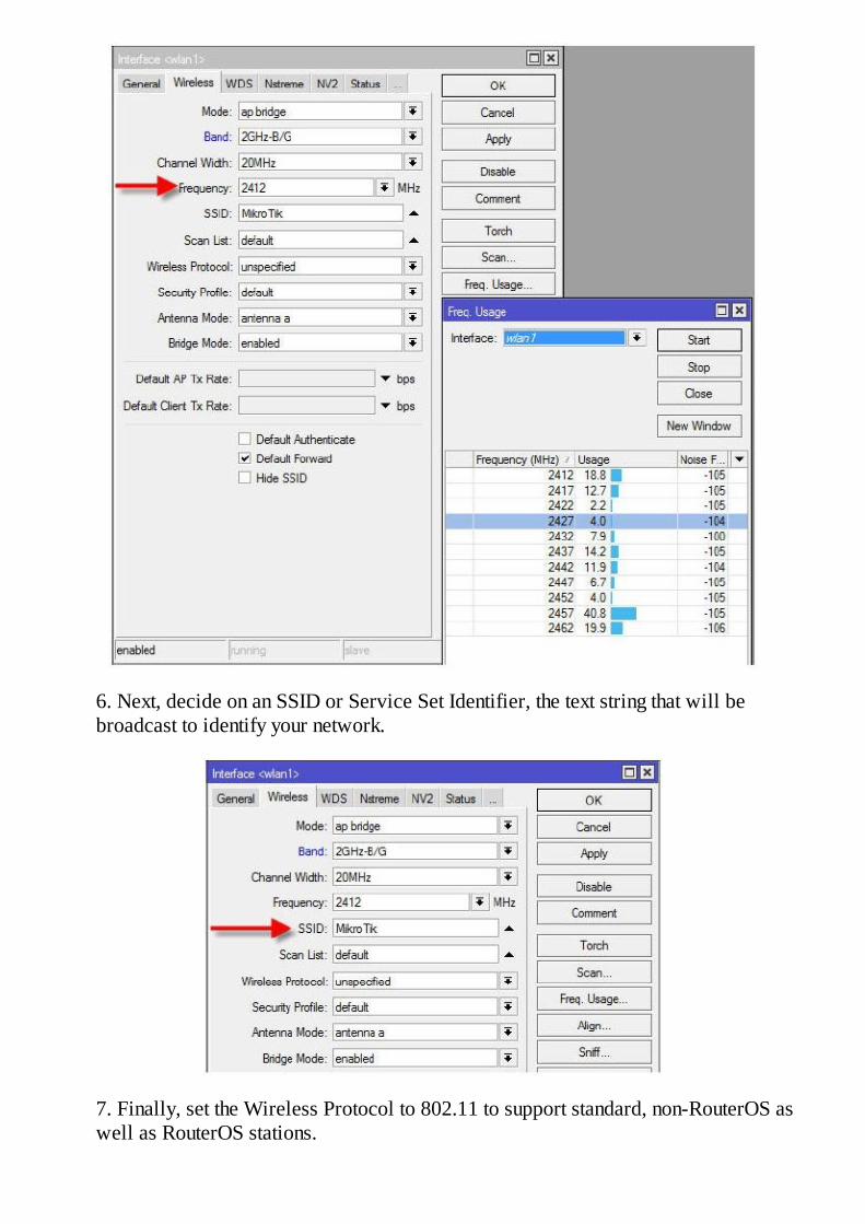
6. Next, decide on an SSID or Service Set Identifier, the text string that will bebroadcast to identify your network.
7. Finally, set the Wireless Protocol to 802.11 to support standard, non-RouterOS aswell as RouterOS stations.

Next comes security. RouterOS supports several wireless security protocols and the mostcommon are WEP, Wired Equivalency Privacy, and WPA2 or Wi-Fi Protected Access. WEPis antiquated and not very secure yet it is supported for legacy applications. Wireless SecurityProfiles are explained beginning on page 233.
Wireless Security
I always tell my classes that security is not simply a button we push and then walk awayfeeling safe and secure. Instead, we go for a layered approach, understanding that the morelayers we add, the more secure the network will be. In addition, we stress that each layer ofsecurity has a cost and that cost is paid in performance and maintainability. The more complexthe security, that is, the more layers, the more work it is for a potential hacker to get in and themore work it is for us to maintain.
In this book, we discuss several ways to secure your wireless network and again, we opt for alayered approach. The layers that can be applied easily are:
MAC Filtering – Controlling access at the MAC layer. If the station can’t associate, it can’tgain access. MAC filtering can be circumvented by spoofing the MAC address of an allowedstation so it is not very effective for seasoned hackers.
Encryption – WEP, WPA and WPA2 are some encryption protocols supported in RouterOS.By encrypting the data transmission, the network is greatly fortified.
Proprietary Protocols – using Nstreme or NV2 is a way to control access to the network.The hacker will have to use RouterOS to gain access and statistically this helps improve ourodds of resisting attack.
Hiding the SSID – A very basic approach, nevertheless it is effective in keeping the existenceof your wireless network away from most unsophisticated users but true hackers will not evenbe slowed down.
Controlling Access with MAC Lists
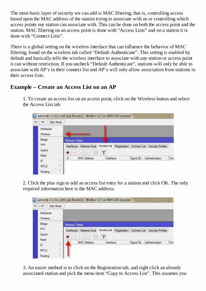
The most basic layer of security we can add is MAC filtering, that is, controlling accessbased upon the MAC address of the station trying to associate with us or controlling whichaccess points our station can associate with. This can be done on both the access point and thestation. MAC filtering on an access point is done with “Access Lists” and on a station it isdone with “Connect Lists”.
There is a global setting on the wireless interface that can influence the behavior of MACfiltering, found on the wireless tab called “Default Authenticate”. This setting is enabled bydefault and basically tells the wireless interface to associate with any station or access pointit can without restriction. If you uncheck “Default Authenticate”, stations will only be able toassociate with AP’s in their connect list and AP’s will only allow association from stations intheir access lists.
Example – Create an Access List on an AP
1. To create an access list on an access point, click on the Wireless button and selectthe Access List tab.
2. Click the plus sign to add an access list entry for a station and click OK. The onlyrequired information here is the MAC address.
3. An easier method is to click on the Registration tab, and right click an alreadyassociated station and pick the menu item “Copy to Access List”. This assumes you
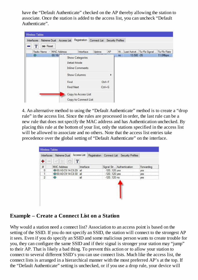
have the “Default Authenticate” checked on the AP thereby allowing the station toassociate. Once the station is added to the access list, you can uncheck “DefaultAuthenticate”.
4. An alternative method to using the “Default Authenticate” method is to create a “droprule” in the access list. Since the rules are processed in order, the last rule can be anew rule that does not specify the MAC address and has Authentication unchecked. Byplacing this rule at the bottom of your list, only the stations specified in the access listwill be allowed to associate and no others. Note that the access list entries takeprecedence over the global setting of “Default Authenticate” on the interface.
Example – Create a Connect List on a Station
Why would a station need a connect list? Association to an access point is based on thesetting of the SSID. If you do not specify an SSID, the station will connect to the strongest APit sees. Even if you do specify an SSID and some malicious person wants to create trouble foryou, they can configure the same SSID and if their signal is stronger your station may “jump”to their AP. That is likely a bad thing. To prevent this action or to allow your station toconnect to several different SSID’s you can use connect lists. Much like the access list, theconnect lists is arranged in a hierarchical manner with the most preferred AP’s at the top. Ifthe “Default Authenticate” setting is unchecked, or if you use a drop rule, your device will
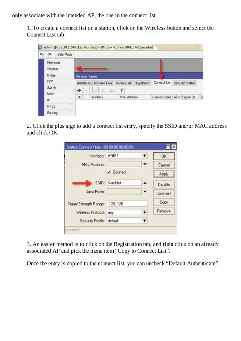
only associate with the intended AP, the one in the connect list.
1. To create a connect list on a station, click on the Wireless button and select theConnect List tab.
2. Click the plus sign to add a connect list entry, specify the SSID and/or MAC addressand click OK.
3. An easier method is to click on the Registration tab, and right click on an alreadyassociated AP and pick the menu item “Copy to Connect List”.
Once the entry is copied to the connect list, you can uncheck “Default Authenticate”.
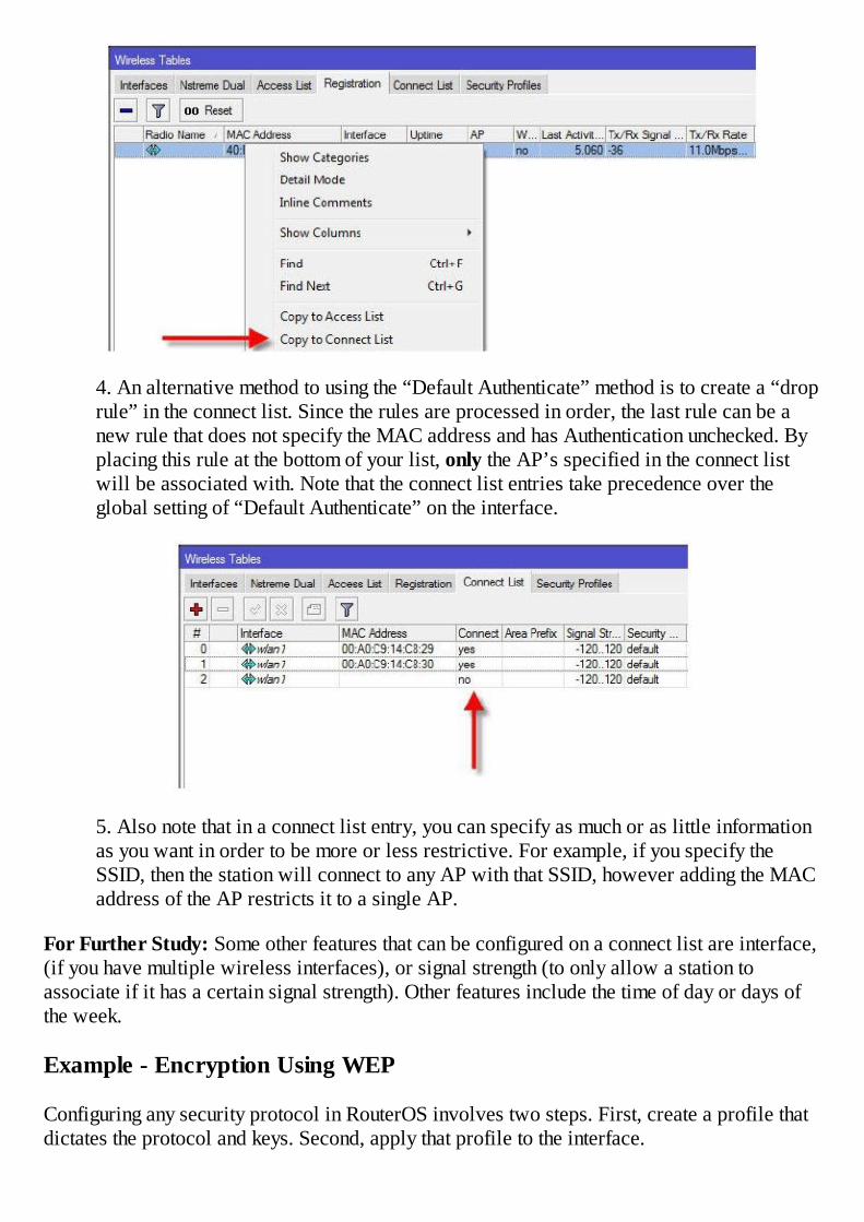
4. An alternative method to using the “Default Authenticate” method is to create a “droprule” in the connect list. Since the rules are processed in order, the last rule can be anew rule that does not specify the MAC address and has Authentication unchecked. Byplacing this rule at the bottom of your list, only the AP’s specified in the connect listwill be associated with. Note that the connect list entries take precedence over theglobal setting of “Default Authenticate” on the interface.
5. Also note that in a connect list entry, you can specify as much or as little informationas you want in order to be more or less restrictive. For example, if you specify theSSID, then the station will connect to any AP with that SSID, however adding the MACaddress of the AP restricts it to a single AP.
For Further Study: Some other features that can be configured on a connect list are interface,(if you have multiple wireless interfaces), or signal strength (to only allow a station toassociate if it has a certain signal strength). Other features include the time of day or days ofthe week.
Example - Encryption Using WEP
Configuring any security protocol in RouterOS involves two steps. First, create a profile thatdictates the protocol and keys. Second, apply that profile to the interface.

To create the security profile for WEP:
1. Click the Wireless button and then the Security Profiles tab. Click the plus sign andcreate a new profile and name it whatever you wish. Change the mode to “Static KeysRequired”.
2. On the Static Keys tab, select Key 0 using the key type you require, typically 40 bitor 104 bit. A 40 bit key is 10 digits and a 104 but key is 26 digits. In the blank type thekey you want to use and then click Ok.
3. Back on the Wireless tab, double click the wireless interface to be configured withsecurity.

4. On the Wireless tab, select the interface and use the pull-down to select the securityprofile you just created.
Example – Encryption Using WPA(2)
To create the security profile for WPA or WPA2:
1. Click the Wireless button and then the security tab. Click the plus sign and create anew profile and name it whatever you wish. Change the mode to “Dynamic Keys”. Forthe Authentication Types, select WPA PSK and/or WPA2 PSK, depending on the typeof security you want to support.
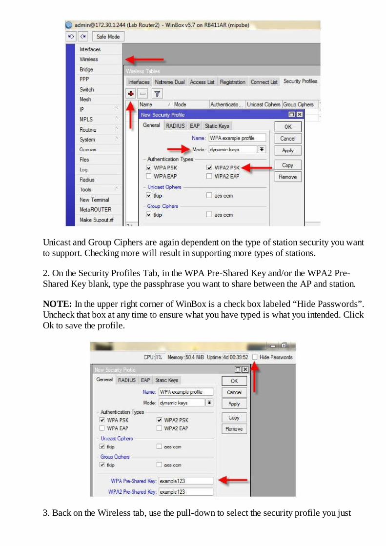
Unicast and Group Ciphers are again dependent on the type of station security you wantto support. Checking more will result in supporting more types of stations.
2. On the Security Profiles Tab, in the WPA Pre-Shared Key and/or the WPA2 Pre-Shared Key blank, type the passphrase you want to share between the AP and station.
NOTE: In the upper right corner of WinBox is a check box labeled “Hide Passwords”.Uncheck that box at any time to ensure what you have typed is what you intended. ClickOk to save the profile.
3. Back on the Wireless tab, use the pull-down to select the security profile you just
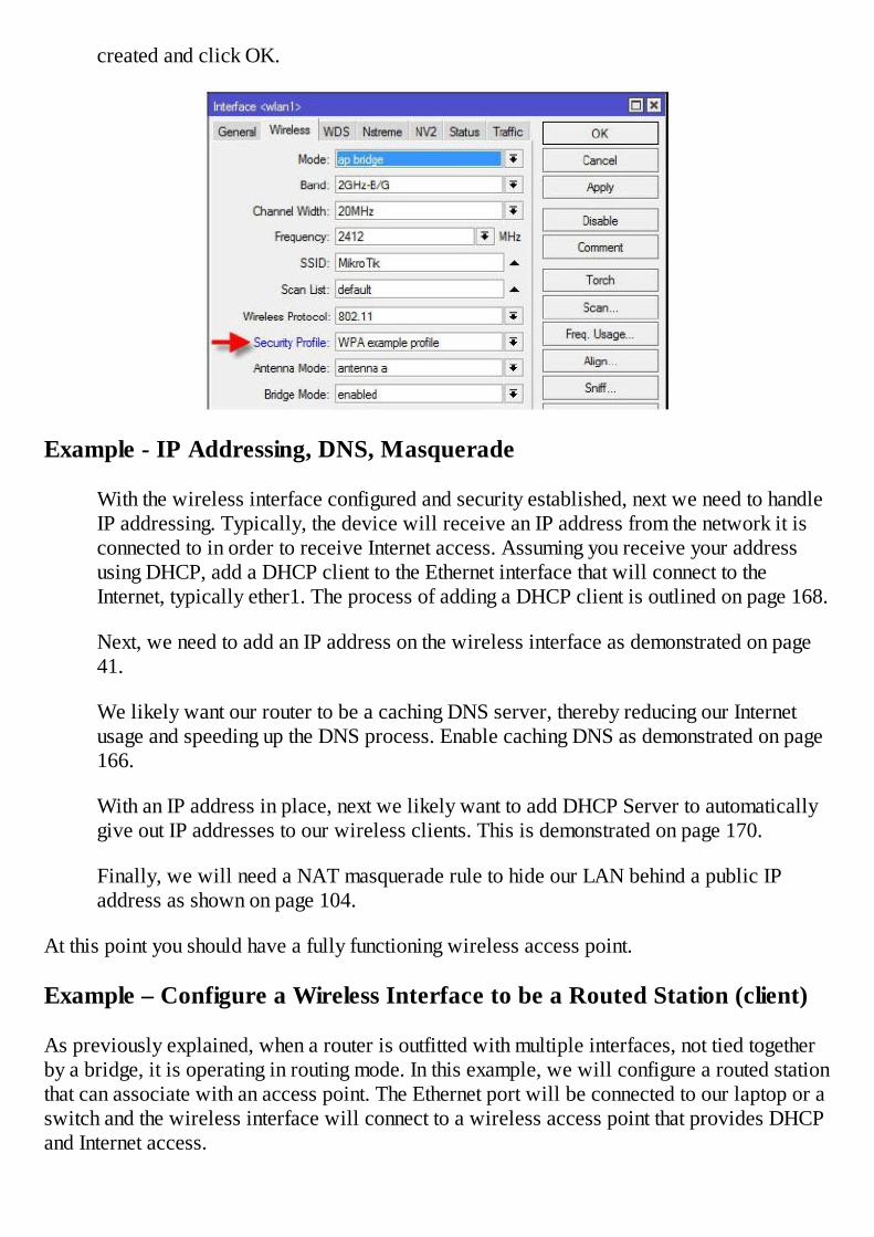
created and click OK.
Example - IP Addressing, DNS, Masquerade
With the wireless interface configured and security established, next we need to handleIP addressing. Typically, the device will receive an IP address from the network it isconnected to in order to receive Internet access. Assuming you receive your addressusing DHCP, add a DHCP client to the Ethernet interface that will connect to theInternet, typically ether1. The process of adding a DHCP client is outlined on page 168.
Next, we need to add an IP address on the wireless interface as demonstrated on page41.
We likely want our router to be a caching DNS server, thereby reducing our Internetusage and speeding up the DNS process. Enable caching DNS as demonstrated on page166.
With an IP address in place, next we likely want to add DHCP Server to automaticallygive out IP addresses to our wireless clients. This is demonstrated on page 170.
Finally, we will need a NAT masquerade rule to hide our LAN behind a public IPaddress as shown on page 104.
At this point you should have a fully functioning wireless access point.
Example – Configure a Wireless Interface to be a Routed Station (client)
As previously explained, when a router is outfitted with multiple interfaces, not tied togetherby a bridge, it is operating in routing mode. In this example, we will configure a routed stationthat can associate with an access point. The Ethernet port will be connected to our laptop or aswitch and the wireless interface will connect to a wireless access point that provides DHCPand Internet access.

1. Click the Wireless button and double click the wireless interface to be configured.
2. The minimum information to be configured is the Mode, the band, the SSID, and theWireless Protocol. Set the Mode to station, the Band to the frequency of your accesspoint (typically 2.4 GHz, 802.11 b/g/n), and the Wireless Protocol to 802.11 and thenclick Apply.
3. If you are unsure of the SSID, you can scan for it using the Scan button and thenclicking Start. This will scan for wireless networks in the band you previouslyspecified.
4. To select an SSID, click the Connect button and that SSID will be loaded into theSSID blank. Stop and close the Scan tool. The router should then be connected to theAP. If the AP requires security, it can be configured exactly the same way as securityfor an access point as described on page 233.
5. At this point the wireless station should be associated with the access point.
6. Add DHCP client to the wireless interface as shown on page 168.
7. Add an IP address to the Ethernet interface as shown on page 41.
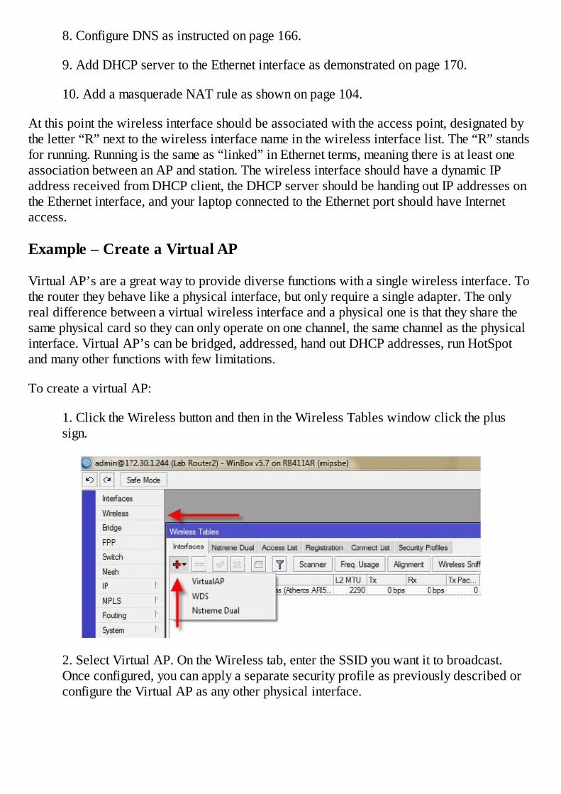
8. Configure DNS as instructed on page 166.
9. Add DHCP server to the Ethernet interface as demonstrated on page 170.
10. Add a masquerade NAT rule as shown on page 104.
At this point the wireless interface should be associated with the access point, designated bythe letter “R” next to the wireless interface name in the wireless interface list. The “R” standsfor running. Running is the same as “linked” in Ethernet terms, meaning there is at least oneassociation between an AP and station. The wireless interface should have a dynamic IPaddress received from DHCP client, the DHCP server should be handing out IP addresses onthe Ethernet interface, and your laptop connected to the Ethernet port should have Internetaccess.
Example – Create a Virtual AP
Virtual AP’s are a great way to provide diverse functions with a single wireless interface. Tothe router they behave like a physical interface, but only require a single adapter. The onlyreal difference between a virtual wireless interface and a physical one is that they share thesame physical card so they can only operate on one channel, the same channel as the physicalinterface. Virtual AP’s can be bridged, addressed, hand out DHCP addresses, run HotSpotand many other functions with few limitations.
To create a virtual AP:
1. Click the Wireless button and then in the Wireless Tables window click the plussign.
2. Select Virtual AP. On the Wireless tab, enter the SSID you want it to broadcast.Once configured, you can apply a separate security profile as previously described orconfigure the Virtual AP as any other physical interface.

Bridging – Point to Point or Point to Multi-Point
There are several ways to bridge a RouterOS device but the goal is always the same. Joindissimilar physical interfaces into one logical interface. RouterOS support several methods ofbridging, but I advocate only one, station-wds mode. This method can be used in a mixedwireless network, that is, an access point that will support routed stations as well as bridgedstations.
Bridging an access point is straightforward and completely accepted in the IEEE 802.11standard. Bridging a device while configured in station mode is not acceptable in the IEEstandard and for that reason we need a workaround to perform bridging. The wireless modethat will enable bridging a station is named “station-wds” mode and is simple to set up on thestation but requires support on the access point. Both configurations will be described here.
Example – Transparently Bridging a Link
Station End
1. To bridge the station device, click the Wireless button and then double click thewireless interface.
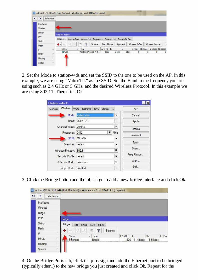
2. Set the Mode to station-wds and set the SSID to the one to be used on the AP. In thisexample, we are using “MikroTik” as the SSID. Set the Band to the frequency you areusing such as 2.4 GHz or 5 GHz, and the desired Wireless Protocol. In this example weare using 802.11. Then click Ok.
3. Click the Bridge button and the plus sign to add a new bridge interface and click Ok.
4. On the Bridge Ports tab, click the plus sign and add the Ethernet port to be bridged(typically ether1) to the new bridge you just created and click Ok. Repeat for the
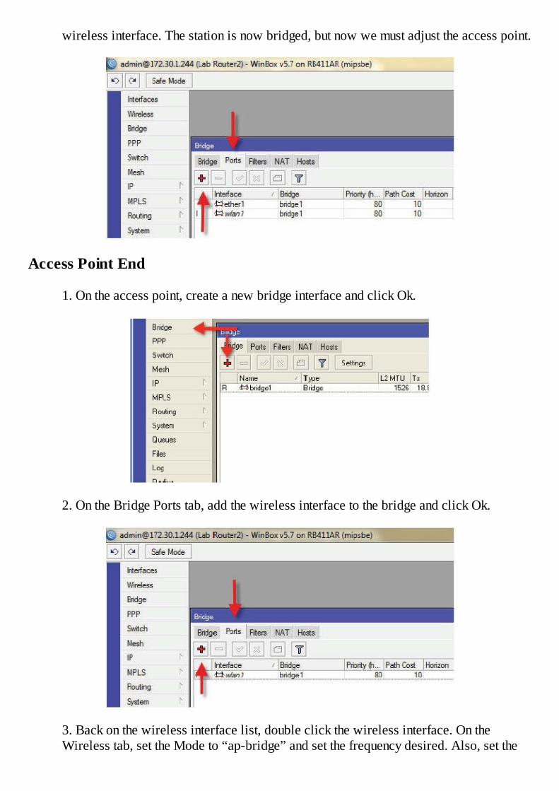
wireless interface. The station is now bridged, but now we must adjust the access point.
Access Point End
1. On the access point, create a new bridge interface and click Ok.
2. On the Bridge Ports tab, add the wireless interface to the bridge and click Ok.
3. Back on the wireless interface list, double click the wireless interface. On theWireless tab, set the Mode to “ap-bridge” and set the frequency desired. Also, set the

SSID you want to use, in this example it is “MikroTik”. Finally set the desired WirelessProtocol. We are using 802.11.
4. On the WDS tab, select WDS Mode as dynamic and WDS Default Bridge as thebridge you created, typically bridge1. It may be necessary to disable and re-enable thewireless interface on the station to cause it to re-associate with the access point nowthat is supports WDS.
5. If you want the access point to be completely bridged, that is, wireless to Ethernet,simply add its Ethernet interface as another port on the AP’s bridge.
Point to Point Links
If your access point is being used with a single station as in a backhaul or point-to-point link,you can set the wireless mode to “bridge”. This mode is available in the Level 3 licensewhile ap-bridge mode is not available in the Level 3 license. In bridge mode, the device isstill an access point, but will only support one station, ideal for low cost point-to-point links.
Example – Pseudobridge Modes
In some scenarios, it is not possible to use an access point that supports WDS. If the stationmust still be bridged, as a last resort, you may use one of the two pseudo bridge modes. I statethat with reluctance because any mode that defies the standard, is fraught with possible
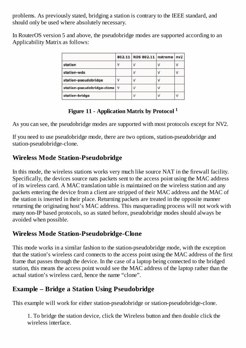
problems. As previously stated, bridging a station is contrary to the IEEE standard, andshould only be used where absolutely necessary.
In RouterOS version 5 and above, the pseudobridge modes are supported according to anApplicability Matrix as follows:
Figure 11 - Application Matrix by Protocol 1
As you can see, the pseudobridge modes are supported with most protocols except for NV2.
If you need to use pseudobridge mode, there are two options, station-pseudobridge andstation-pseudobridge-clone.
Wireless Mode Station-Pseudobridge
In this mode, the wireless stations works very much like source NAT in the firewall facility.Specifically, the devices source nats packets sent to the access point using the MAC addressof its wireless card. A MAC translation table is maintained on the wireless station and anypackets entering the device from a client are stripped of their MAC address and the MAC ofthe station is inserted in their place. Returning packets are treated in the opposite mannerreturning the originating host’s MAC address. This masquerading process will not work withmany non-IP based protocols, so as stated before, pseudobridge modes should always beavoided when possible.
Wireless Mode Station-Pseudobridge-Clone
This mode works in a similar fashion to the station-pseudobridge mode, with the exceptionthat the station’s wireless card connects to the access point using the MAC address of the firstframe that passes through the device. In the case of a laptop being connected to the bridgedstation, this means the access point would see the MAC address of the laptop rather than theactual station’s wireless card, hence the name “clone”.
Example – Bridge a Station Using Pseudobridge
This example will work for either station-pseudobridge or station-pseudobridge-clone.
1. To bridge the station device, click the Wireless button and then double click thewireless interface.

2. Set the mode to station-pseudobridge or station-pseudobridge-clone mode and clickOk.
3. Click the bridge button and the plus sign to add a new bridge interface and click Ok.
4. On the Ports tab, click the plus sign and add the Ethernet port to be bridged (typicallyether1) to the new bridge you just created and click Ok. Repeat for the wireless

interface.
The station is now bridged.
For Further Study: It is also possible to bridge two devices using a PPP tunnel, EoIP tunnel,or VPLS.
Supporting Mixed Clients, Routed Stations and Bridged Stations
Once WDS bridging is set up on an access point as demonstrated on page 242, it is possibleto support both routed stations and bridged stations that have been configured using thetransparent bridging method. This is a good scenario for Internet service providers as it givesthem several different customer configurations they can offer.
For example, if a customer wants a standard, managed connection, using a routed station,firewalling, private addressing on the LAN, public addressing on the WAN, and the ability tosupport destination NAT for inbound services to servers on the LAN, this is all possible usinga standard routed station. If the access point is configured with support for WDS clients asoutlined on page 242, that makes it possible to offer an alternate configuration on the sameaccess point for non-managed clients. For example, if a client wants to run their own routerand firewall and have it receive a public IP address via your PPPoE server, again that can bedone by configuring that station in station-wds mode. Since the AP supports both WDS andnon-WDS clients, one access point can support either configuration and neither of thesescenarios require station-pseudobridge mode, although that is still supported.
WDS, Wireless Distribution System
In some scenarios, it is desired to provide wireless access, yet it is not possible to getnetwork cabling in place to the access point. This scenario lends itself well to a protocolcalled WDS. We have previously used a function of this protocol to create a transparentwireless bridge, yet the true power of WDS is the application just described. In a WDSsystem, each access point serves double duty in that it acts as both an access point and astation at the same time. This is both helpful and hurtful at the same time so let me explain.
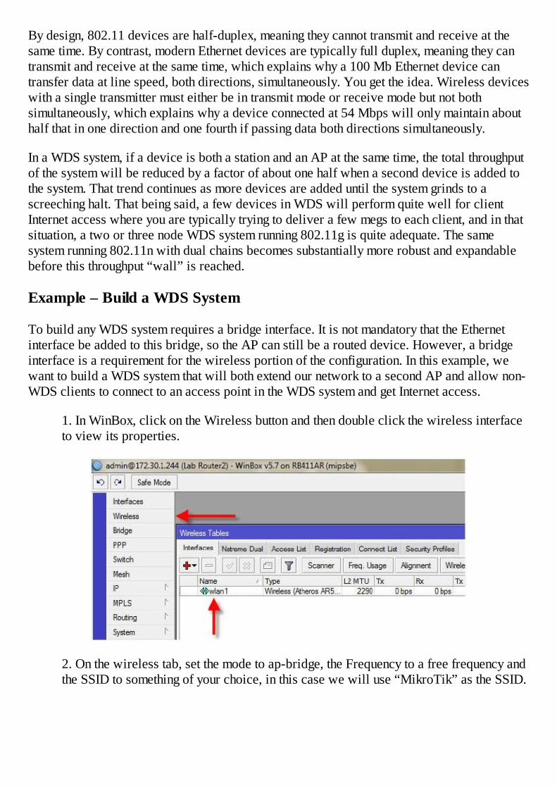
By design, 802.11 devices are half-duplex, meaning they cannot transmit and receive at thesame time. By contrast, modern Ethernet devices are typically full duplex, meaning they cantransmit and receive at the same time, which explains why a 100 Mb Ethernet device cantransfer data at line speed, both directions, simultaneously. You get the idea. Wireless deviceswith a single transmitter must either be in transmit mode or receive mode but not bothsimultaneously, which explains why a device connected at 54 Mbps will only maintain abouthalf that in one direction and one fourth if passing data both directions simultaneously.
In a WDS system, if a device is both a station and an AP at the same time, the total throughputof the system will be reduced by a factor of about one half when a second device is added tothe system. That trend continues as more devices are added until the system grinds to ascreeching halt. That being said, a few devices in WDS will perform quite well for clientInternet access where you are typically trying to deliver a few megs to each client, and in thatsituation, a two or three node WDS system running 802.11g is quite adequate. The samesystem running 802.11n with dual chains becomes substantially more robust and expandablebefore this throughput “wall” is reached.
Example – Build a WDS System
To build any WDS system requires a bridge interface. It is not mandatory that the Ethernetinterface be added to this bridge, so the AP can still be a routed device. However, a bridgeinterface is a requirement for the wireless portion of the configuration. In this example, wewant to build a WDS system that will both extend our network to a second AP and allow non-WDS clients to connect to an access point in the WDS system and get Internet access.
1. In WinBox, click on the Wireless button and then double click the wireless interfaceto view its properties.
2. On the wireless tab, set the mode to ap-bridge, the Frequency to a free frequency andthe SSID to something of your choice, in this case we will use “MikroTik” as the SSID.

3. Create a new bridge interface and click Ok.
4. On the ports tab, add the wireless interface to the bridge and click Ok.
5. Back on the wireless interface list, double click the wireless interface and on theWDS tab, select WDS Mode as dynamic and WDS Default Bridge as the bridge youcreated, typically bridge1.
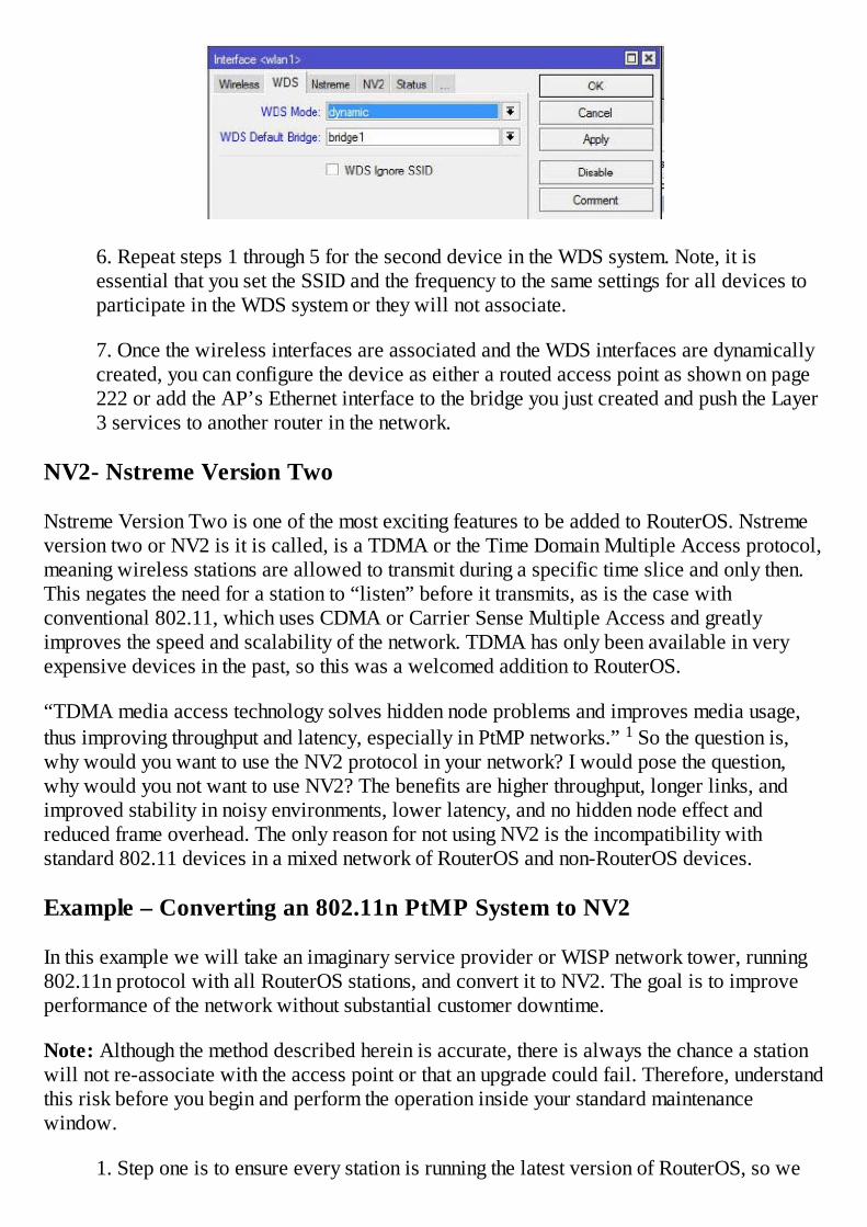
6. Repeat steps 1 through 5 for the second device in the WDS system. Note, it isessential that you set the SSID and the frequency to the same settings for all devices toparticipate in the WDS system or they will not associate.
7. Once the wireless interfaces are associated and the WDS interfaces are dynamicallycreated, you can configure the device as either a routed access point as shown on page222 or add the AP’s Ethernet interface to the bridge you just created and push the Layer3 services to another router in the network.
NV2- Nstreme Version Two
Nstreme Version Two is one of the most exciting features to be added to RouterOS. Nstremeversion two or NV2 is it is called, is a TDMA or the Time Domain Multiple Access protocol,meaning wireless stations are allowed to transmit during a specific time slice and only then.This negates the need for a station to “listen” before it transmits, as is the case withconventional 802.11, which uses CDMA or Carrier Sense Multiple Access and greatlyimproves the speed and scalability of the network. TDMA has only been available in veryexpensive devices in the past, so this was a welcomed addition to RouterOS.
“TDMA media access technology solves hidden node problems and improves media usage,thus improving throughput and latency, especially in PtMP networks.” 1 So the question is,why would you want to use the NV2 protocol in your network? I would pose the question,why would you not want to use NV2? The benefits are higher throughput, longer links, andimproved stability in noisy environments, lower latency, and no hidden node effect andreduced frame overhead. The only reason for not using NV2 is the incompatibility withstandard 802.11 devices in a mixed network of RouterOS and non-RouterOS devices.
Example – Converting an 802.11n PtMP System to NV2
In this example we will take an imaginary service provider or WISP network tower, running802.11n protocol with all RouterOS stations, and convert it to NV2. The goal is to improveperformance of the network without substantial customer downtime.
Note: Although the method described herein is accurate, there is always the chance a stationwill not re-associate with the access point or that an upgrade could fail. Therefore, understandthis risk before you begin and perform the operation inside your standard maintenancewindow.
1. Step one is to ensure every station is running the latest version of RouterOS, so we
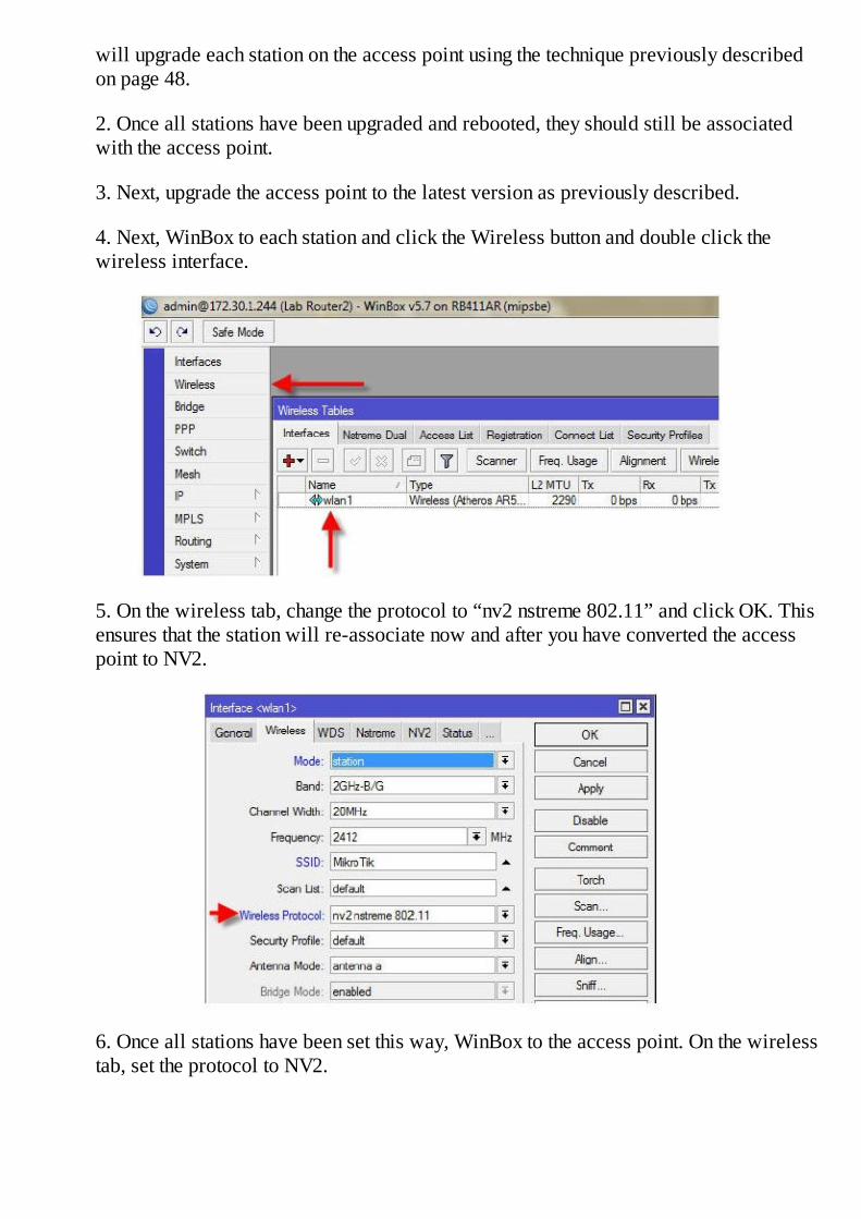
will upgrade each station on the access point using the technique previously describedon page 48.
2. Once all stations have been upgraded and rebooted, they should still be associatedwith the access point.
3. Next, upgrade the access point to the latest version as previously described.
4. Next, WinBox to each station and click the Wireless button and double click thewireless interface.
5. On the wireless tab, change the protocol to “nv2 nstreme 802.11” and click OK. Thisensures that the station will re-associate now and after you have converted the accesspoint to NV2.
6. Once all stations have been set this way, WinBox to the access point. On the wirelesstab, set the protocol to NV2.
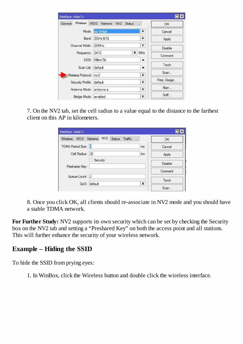
7. On the NV2 tab, set the cell radius to a value equal to the distance to the farthestclient on this AP in kilometers.
8. Once you click OK, all clients should re-associate in NV2 mode and you should havea stable TDMA network.
For Further Study: NV2 supports its own security which can be set by checking the Securitybox on the NV2 tab and setting a “Preshared Key” on both the access point and all stations.This will further enhance the security of your wireless network.
Example – Hiding the SSID
To hide the SSID from prying eyes:
1. In WinBox, click the Wireless button and double click the wireless interface.

2. On the wireless tab, check the box “hide SSID”.


Chapter 16 – Routing
In simplest terms, routing is the process that determines the interface through which a packetleaves a router. Routing takes place at Layer 3 and the process is governed by a list of rulescalled routes. When a packet enters the routing process, the router looks at the destination IPaddress of the packet and then compares that address to the route rules to determine where tosend the packet.
There are some basic rules that govern simple routing. First, routers can only send packets torouters they are directly connected to. By directly connected, I am describing two routers witha Layer 1 connection, such as an Ethernet cable or wireless link connecting them, both ofwhose interfaces are configured with IP addresses on the same subnet. Understanding thisterm “directly connected” is essential in understanding IP routing. Secondly, routers have to“trust” that the router to which they send a packet can ultimately get the packet to its finaldestination. To explain this “trust” relationship, consider the following example:
Figure 12 - Routing Diagram
Router A needs to send a packet to the 192.168.100.0/24 subnet, which is directly connected,to Router C. Since A is not directly connected to C, it must send the packet to B and “trust” Bcan get the packet to its final destination. Why does it send the packet to B? Because RouterA’s routing table or routing “rules” tell it that Router B is the gateway for the192.168.100.0/24 subnet. With routing, there is no “leap frogging”, meaning that A must sendthe packet to B who sends the packet to C and A can not “leap frog” over B and send packetsdirectly to C.
This concept of sending packets to an adjacent or directly connected router is referred to asthe “next hop”, which is descriptive of a packet hopping from Router A and then to Router Band Router C and finally to the destination subnet. In this scenario the next hop for router A isRouter B.
Simple Static Routes
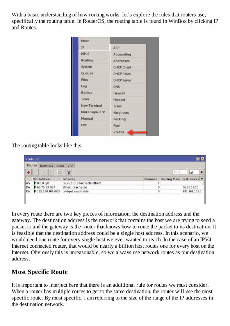
With a basic understanding of how routing works, let’s explore the rules that routers use,specifically the routing table. In RouterOS, the routing table is found in WinBox by clicking IPand Routes.
The routing table looks like this:
In every route there are two key pieces of information, the destination address and thegateway. The destination address is the network that contains the host we are trying to send apacket to and the gateway is the router that knows how to route the packet to its destination. Itis feasible that the destination address could be a single host address. In this scenario, wewould need one route for every single host we ever wanted to reach. In the case of an IPV4Internet connected router, that would be nearly a billion host routes one for every host on theInternet. Obviously this is unreasonable, so we always use network routes as our destinationaddress.
Most Specific Route
It is important to interject here that there is an additional rule for routes we must consider.When a router has multiple routes to get to the same destination, the router will use the mostspecific route. By most specific, I am referring to the size of the range of the IP addresses inthe destination network.
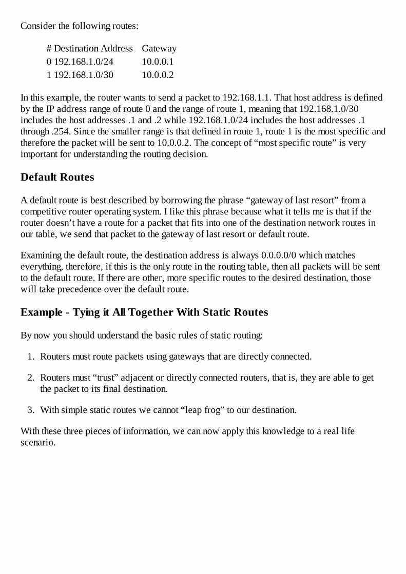
Consider the following routes:
# Destination Address Gateway0 192.168.1.0/24 10.0.0.11 192.168.1.0/30 10.0.0.2
In this example, the router wants to send a packet to 192.168.1.1. That host address is definedby the IP address range of route 0 and the range of route 1, meaning that 192.168.1.0/30includes the host addresses .1 and .2 while 192.168.1.0/24 includes the host addresses .1through .254. Since the smaller range is that defined in route 1, route 1 is the most specific andtherefore the packet will be sent to 10.0.0.2. The concept of “most specific route” is veryimportant for understanding the routing decision.
Default Routes
A default route is best described by borrowing the phrase “gateway of last resort” from acompetitive router operating system. I like this phrase because what it tells me is that if therouter doesn’t have a route for a packet that fits into one of the destination network routes inour table, we send that packet to the gateway of last resort or default route.
Examining the default route, the destination address is always 0.0.0.0/0 which matcheseverything, therefore, if this is the only route in the routing table, then all packets will be sentto the default route. If there are other, more specific routes to the desired destination, thosewill take precedence over the default route.
Example - Tying it All Together With Static Routes
By now you should understand the basic rules of static routing:
1. Routers must route packets using gateways that are directly connected.
2. Routers must “trust” adjacent or directly connected routers, that is, they are able to getthe packet to its final destination.
3. With simple static routes we cannot “leap frog” to our destination.
With these three pieces of information, we can now apply this knowledge to a real lifescenario.
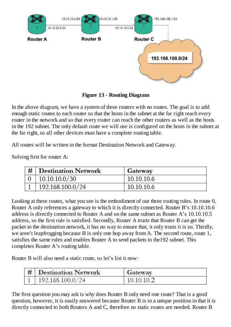
Figure 13 - Routing Diagram
In the above diagram, we have a system of three routers with no routes. The goal is to addenough static routes to each router so that the hosts in the subnet at the far right reach everyrouter in the network and so that every router can reach the other routers as well as the hostsin the 192 subnet. The only default route we will use is configured on the hosts in the subnet atthe far right, so all other devices must have a complete routing table.
All routes will be written in the format Destination Network and Gateway.
Solving first for router A:
Looking at these routes, what you see is the embodiment of our three routing rules. In route 0,Router A only references a gateway to which it is directly connected. Router B’s 10.10.10.6address is directly connected to Router A and on the same subnet as Router A’s 10.10.10.5address, so the first rule is satisfied. Secondly, Router A trusts that Router B can get thepacket to the destination network, it has no way to ensure that, it only trusts it is so. Thirdly,we aren’t leapfrogging because B is only one hop away from A. The second route, route 1,satisfies the same rules and enables Router A to send packets to the192 subnet. Thiscompletes Router A’s routing table.
Router B will also need a static route, so let’s list it now:
The first question you may ask is why does Router B only need one route? That is a goodquestion, however, it is easily answered because Router B is in a unique position in that it isdirectly connected to both Routers A and C, therefore no static routes are needed. Router B
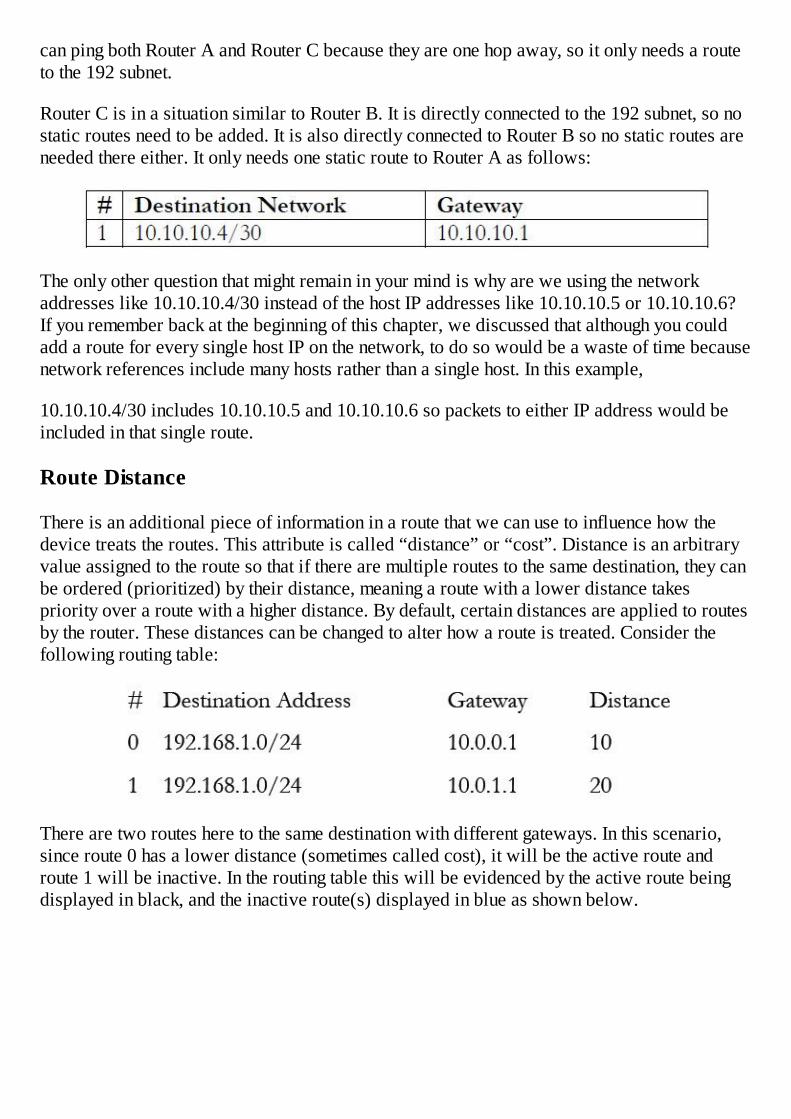
can ping both Router A and Router C because they are one hop away, so it only needs a routeto the 192 subnet.
Router C is in a situation similar to Router B. It is directly connected to the 192 subnet, so nostatic routes need to be added. It is also directly connected to Router B so no static routes areneeded there either. It only needs one static route to Router A as follows:
The only other question that might remain in your mind is why are we using the networkaddresses like 10.10.10.4/30 instead of the host IP addresses like 10.10.10.5 or 10.10.10.6?If you remember back at the beginning of this chapter, we discussed that although you couldadd a route for every single host IP on the network, to do so would be a waste of time becausenetwork references include many hosts rather than a single host. In this example,
10.10.10.4/30 includes 10.10.10.5 and 10.10.10.6 so packets to either IP address would beincluded in that single route.
Route Distance
There is an additional piece of information in a route that we can use to influence how thedevice treats the routes. This attribute is called “distance” or “cost”. Distance is an arbitraryvalue assigned to the route so that if there are multiple routes to the same destination, they canbe ordered (prioritized) by their distance, meaning a route with a lower distance takespriority over a route with a higher distance. By default, certain distances are applied to routesby the router. These distances can be changed to alter how a route is treated. Consider thefollowing routing table:
There are two routes here to the same destination with different gateways. In this scenario,since route 0 has a lower distance (sometimes called cost), it will be the active route androute 1 will be inactive. In the routing table this will be evidenced by the active route beingdisplayed in black, and the inactive route(s) displayed in blue as shown below.
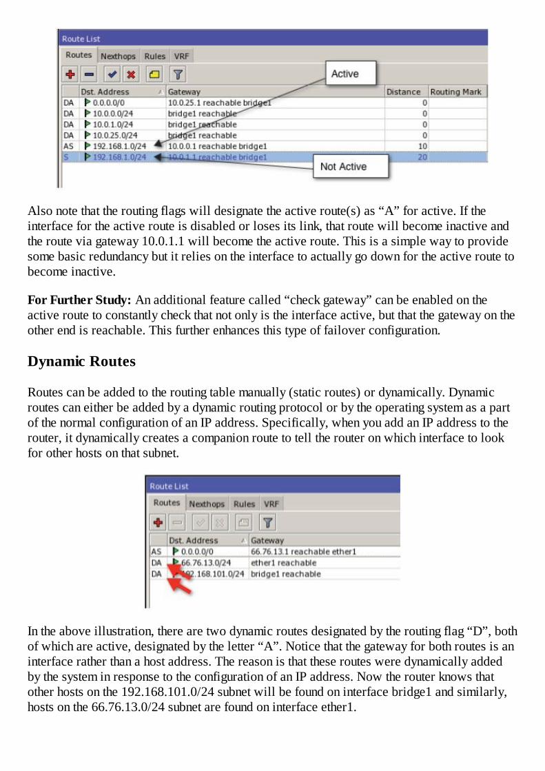
Also note that the routing flags will designate the active route(s) as “A” for active. If theinterface for the active route is disabled or loses its link, that route will become inactive andthe route via gateway 10.0.1.1 will become the active route. This is a simple way to providesome basic redundancy but it relies on the interface to actually go down for the active route tobecome inactive.
For Further Study: An additional feature called “check gateway” can be enabled on theactive route to constantly check that not only is the interface active, but that the gateway on theother end is reachable. This further enhances this type of failover configuration.
Dynamic Routes
Routes can be added to the routing table manually (static routes) or dynamically. Dynamicroutes can either be added by a dynamic routing protocol or by the operating system as a partof the normal configuration of an IP address. Specifically, when you add an IP address to therouter, it dynamically creates a companion route to tell the router on which interface to lookfor other hosts on that subnet.
In the above illustration, there are two dynamic routes designated by the routing flag “D”, bothof which are active, designated by the letter “A”. Notice that the gateway for both routes is aninterface rather than a host address. The reason is that these routes were dynamically addedby the system in response to the configuration of an IP address. Now the router knows thatother hosts on the 192.168.101.0/24 subnet will be found on interface bridge1 and similarly,hosts on the 66.76.13.0/24 subnet are found on interface ether1.
Routing Flags
In the previous illustration, to the left of each route in the route list there is a flag or group ofletters that describes the state or origin of the route. In this example, the flags “A”, “S”, and“D” stand for Active, Static, and Dynamic, respectfully. There are several other routing flagsin RouterOS. Those that appear below in bold are those most common.
X – Disabled, not active
A – Active, in use
D – Dynamic, received from a dynamic routing protocol or added by the operatingsystem
C – Connected, a directly connected host route
S – Static, added manually
R - RIP route, received from the routing information protocol
B – BGP, received from the border gateway protocol
O – Received from the open shortest path first protocol
M – Received from the mesh made easy protocol
B – Blackhole route, packets are silently discarded
U – Unreachable, discards the packets and sends an ICMP unreachable messages
P – Prohibit, discards packet and sends an ICMP communication administratively prohibitedmessage
OSPF – A Dynamic Routing Protocol
OSPF or Open Shortest Path First is the name of a simple to configure yet robust routingprotocol anyone can implement and should implement in their networks as they grow past asingle router. OSPF routers dynamically trade routing information as well as the state of thelinks that join routers together and thereby determine the best path between routers. If a pathbecomes unreachable, they adjust their routes accordingly to maintain the reachability of allhosts in the OSPF cloud.
OSPF provides two main benefits. First is the automatic propagation of routes in a networkand the second is failover to ensure the reliability of an IP network.
In this book, we will explore the basics of the OSPF protocol and learn how to create basicOSPF networks that will provide all the routes necessary for the networks to operate withoutusing static routes.
Link State Protocol
The basic communication of an OSPF network is done using the link state protocol. Thisprotocol begins working when two routers in a network are similarly configured with OSPFand the first OSPF packet is sent. This packet is called a “hello packet”. The hello packet isthe first phase of the OSPF neighbor negotiation.
The second phase is called the link state advertisement or LSA. This communication involvessending a list of all the OSPF neighbors the router has learned. This link state information issent by “flooding” LSA’s (Link State Announcements) or sending the LSA’s to every OSPFinterface on the router. If a router receives a packet already seen, it is discarded so the routeronly processes new LSA’s.
Once a router has learned all of its neighbors and all the neighbors they know, it builds a LinkState Database. Once the link state database is fully populated, the routers begin the final andmost complex portion of the process, calculating the routes. This particular algorithmoriginally proposed by Dutch computer scientist Edsger Dijkstra2. Dijkstra’s Algorithm worksby constructing a tree of the network. The tree’s root is the system performing the calculationsand its branches are linked to other systems. The result is the shortest path to each router in thesystem. If a link fails, all routers in the system must perform a new set of calculations and thisresults in utilizing router resources3. Networks with unstable links are not good candidates forOSPF as the constant recalculation of these routes can utilize a large amount of resources. Thenetwork should be stabilized before configuring OSPF.
Areas
The concept of OSPF areas is included in the advanced RouterOS certifications andassociated training but a basic discussion is necessary for purposes of the configurationsdiscussed in this book. The purpose of OSPF areas is to organize or group OSPF routers inlogical divisions in the network. These divisions are typically made with some basis ofgeography, proximity, or function. OSPF routers are typically all contained within one AS orAutonomous System. In simple terms, an AS is a group of routers controlled or owned by asingle entity. When the number of routers within that AS becomes too large or unwieldy, it canbe broken up into smaller groups or OSPF areas.
By default, there is an OSPF area named backbone. For purposes of a small OSPF network,all routers can be made members of the backbone area. As the network groups, additionalareas will become desirable, but these areas will continue to have some attachment to thisbackbone area.
When a new area is created and routers are assigned to this area, they operate as standardOSPF routers flooding their LSA’s, building their databases, and performing their routecalculations. This information is only shared with other routers in their particular area (ifthere are multiple areas). If one router in the area is also connected to the special area calledbackbone, it becomes a special type of router called an ABR or Area Border Router. TheABR is special in that it participates in normal OSPF functions inside its area but on thebackbone interface it only sends a special type of LSA called a summary LSA. The summary
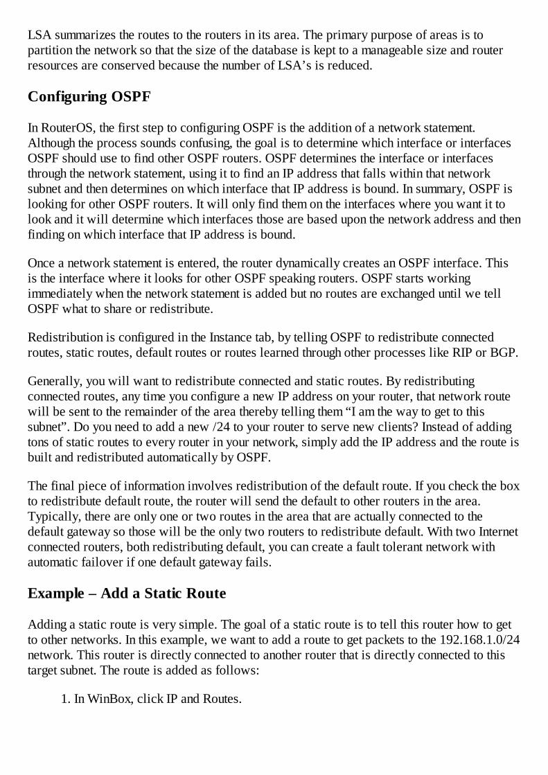
LSA summarizes the routes to the routers in its area. The primary purpose of areas is topartition the network so that the size of the database is kept to a manageable size and routerresources are conserved because the number of LSA’s is reduced.
Configuring OSPF
In RouterOS, the first step to configuring OSPF is the addition of a network statement.Although the process sounds confusing, the goal is to determine which interface or interfacesOSPF should use to find other OSPF routers. OSPF determines the interface or interfacesthrough the network statement, using it to find an IP address that falls within that networksubnet and then determines on which interface that IP address is bound. In summary, OSPF islooking for other OSPF routers. It will only find them on the interfaces where you want it tolook and it will determine which interfaces those are based upon the network address and thenfinding on which interface that IP address is bound.
Once a network statement is entered, the router dynamically creates an OSPF interface. Thisis the interface where it looks for other OSPF speaking routers. OSPF starts workingimmediately when the network statement is added but no routes are exchanged until we tellOSPF what to share or redistribute.
Redistribution is configured in the Instance tab, by telling OSPF to redistribute connectedroutes, static routes, default routes or routes learned through other processes like RIP or BGP.
Generally, you will want to redistribute connected and static routes. By redistributingconnected routes, any time you configure a new IP address on your router, that network routewill be sent to the remainder of the area thereby telling them “I am the way to get to thissubnet”. Do you need to add a new /24 to your router to serve new clients? Instead of addingtons of static routes to every router in your network, simply add the IP address and the route isbuilt and redistributed automatically by OSPF.
The final piece of information involves redistribution of the default route. If you check the boxto redistribute default route, the router will send the default to other routers in the area.Typically, there are only one or two routes in the area that are actually connected to thedefault gateway so those will be the only two routers to redistribute default. With two Internetconnected routers, both redistributing default, you can create a fault tolerant network withautomatic failover if one default gateway fails.
Example – Add a Static Route
Adding a static route is very simple. The goal of a static route is to tell this router how to getto other networks. In this example, we want to add a route to get packets to the 192.168.1.0/24network. This router is directly connected to another router that is directly connected to thistarget subnet. The route is added as follows:
1. In WinBox, click IP and Routes.

2. Click the plus sign and enter the destination address of 192.168.1.0/24.
3. On the gateway blank, type 10.0.0.2 which is the IP address of the directly connectedrouter that is attached to our router as well as the destination subnet.
4. Click Ok.
Example – Add a Default Route
Adding a default route is exactly like a static route. The goal of a default route is to give therouter a place to send all packets for which it does not have a specific route. This router is
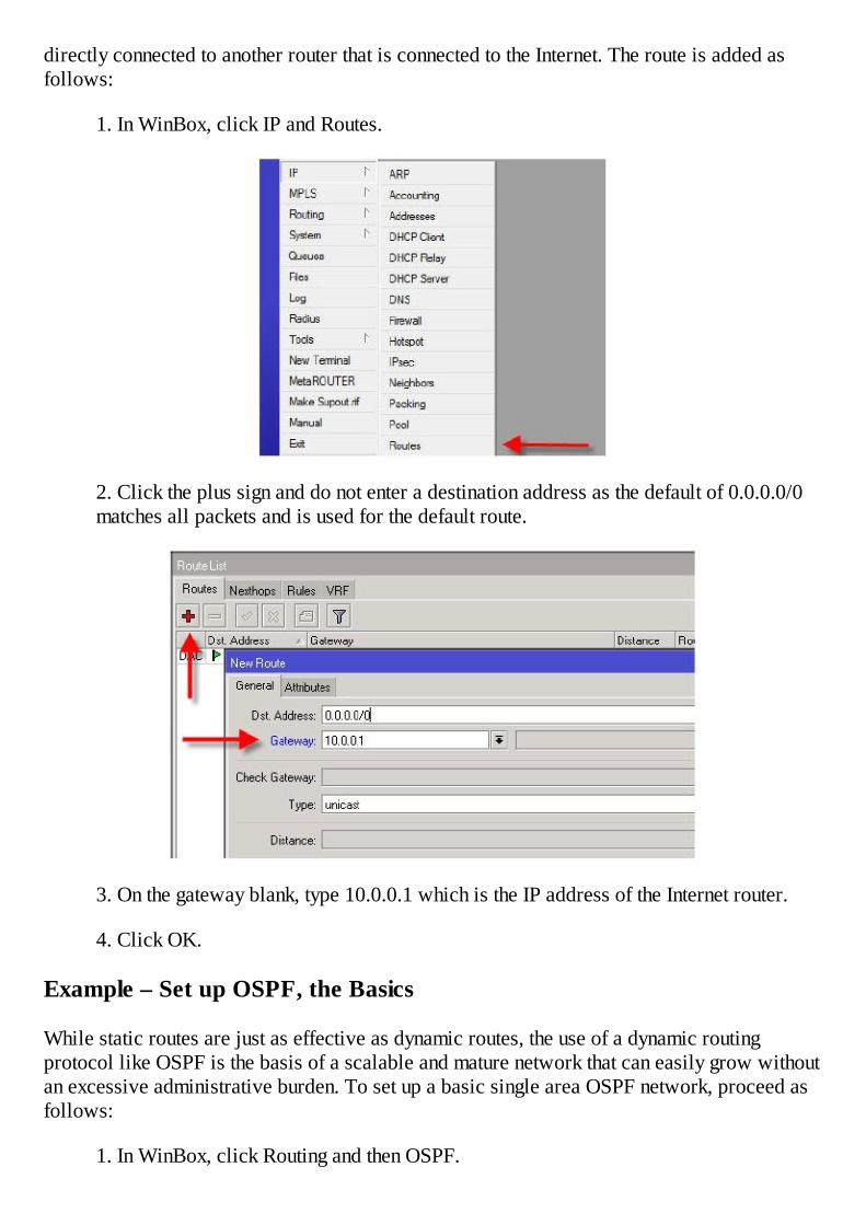
directly connected to another router that is connected to the Internet. The route is added asfollows:
1. In WinBox, click IP and Routes.
2. Click the plus sign and do not enter a destination address as the default of 0.0.0.0/0matches all packets and is used for the default route.
3. On the gateway blank, type 10.0.0.1 which is the IP address of the Internet router.
4. Click OK.
Example – Set up OSPF, the Basics
While static routes are just as effective as dynamic routes, the use of a dynamic routingprotocol like OSPF is the basis of a scalable and mature network that can easily grow withoutan excessive administrative burden. To set up a basic single area OSPF network, proceed asfollows:
1. In WinBox, click Routing and then OSPF.

2. Assume we are building a network according to the following diagram. Even thoughour router has several interfaces and numerous IP addresses, we have selected amanagement network on which we will run OSPF. These networks all fall within10.10.10.X/X.
Figure 14 - OSPF Network
3. Now consider router A. It has multiple interfaces with multiple subnets, but we onlywant to run OSPF with neighbors B, C, and D and not Z. To do this, click on theNetworks tab and then the plus sign. Enter the network address of the network on whichyou will run OSPF. Notice we do not add the 192.168.1.0/30 network as we do notwant OSPF configured on that interface.
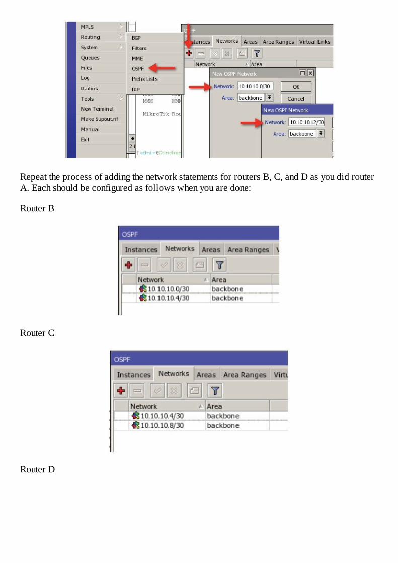
Repeat the process of adding the network statements for routers B, C, and D as you did routerA. Each should be configured as follows when you are done:
Router B
Router C
Router D
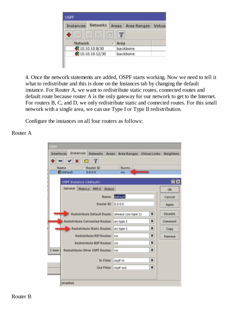
4. Once the network statements are added, OSPF starts working. Now we need to tell itwhat to redistribute and this is done on the Instances tab by changing the defaultinstance. For Router A, we want to redistribute static routes, connected routes anddefault route because router A is the only gateway for our network to get to the Internet.For routers B, C, and D, we only redistribute static and connected routes. For this smallnetwork with a single area, we can use Type I or Type II redistribution.
Configure the instances on all four routers as follows:
Router A
Router B

Router C
Router D
Check the routing table now and you should now see routes to all of the networks configuredon all four routers as well as a default route.

For Further Study:
1. As networks grow, multiple areas can enhance network performance by reducing the sizeof the database and make the network more scalable. Consider dividing the network intomultiple areas once you understand the OSPF basics.
2. Using Type I or Type II redistribution is appropriate for multiple areas. With moreexperience in using OSPF, consider changing redistribution types as appropriate toengineer traffic flow.
3. You should also consider using authentication between your OSPF routers to enhancesecurity as well as using passive interfaces and setting a designated router through thepriority setting.


Chapter 17 – VPN Tunnels
General
VPN tunnels or Virtual Private Network tunnels are a method of spanning diverse networks ina manner to allow two network devices to communicate with one another as if they were onthe same local area network. Imagine if you will a crowded room full of noisy people withtwo people on opposite ends of the room that need to communicate with each other. Bystretching a pipe across the room and each person speaking into or listening to the end of thepipe, the two would be able to communicate with each other in the noisy, crowded room as ifthey were the only ones in the room. This analogy roughly describes a VPN tunnel, where thetwo people wanting to communicate are the tunnel end point hosts and the crowded, noisyroom is the public Internet. In an actual VPN tunnel, the traffic would follow the same path asother traffic through the Internet, but would be encapsulated or possibly encrypted. When thepacket reaches its destination at the remote end of the tunnel, it is unencrypted and sent to itsdestination.
The most common use of VPN’s is for remote hosts to “dial in” to an office network, therebyallowing the remote device to reach office resources such as printers or file servers as if itwas located on the same private local area network. The transport network becomes invisibleto the remote host and it operates as if it were only one hop away from the office, even thoughthere may be many router hops in between.
Tunnels are either Layer 2 or Layer 3 in design, that is, packets are either carried through thetunnel by routing or by switching. PPtP or Point to Point Tunneling Protocol is one example ofa Layer 3 tunnel while EoIP is an example of a Layer 2 tunnel. With a Layer 3 tunnel, routerson the end points make the decision about which packets to send across the tunnel but withLayer 2 tunnels, all packets are sent through the tunnel like a switch (unless there are Layer 2filters in place to prevent certain types of traffic).
Another application of VPN tunnels is to connect two networks together through the publicInternet. A company may have two or more locations across the world and by using VPNtunnels, they can tie all these locations together as if they were on the same LAN. This allowshosts in all remote locations to use services behind the company firewall in an unimpededmanner.
In this book, we will explore five different types of tunnels:
1. PPTP – The Point to Point Tunneling Protocol is supported in RouterOS as both clientand server. The server would be suitable for a central location and will support amixture of Windows clients, Mac OSX clients, MikroTik routers, or any other standardsbased PPTP client. This is also an easy tunnel to set up between two routers and is aLayer 3 tunnel.
2. L2TP – The Layer 2 Tunneling Protocol is also supported and the setup is exactly thesame as PPTP.
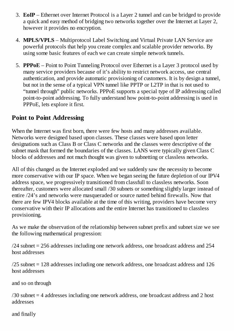
3. EoIP – Ethernet over Internet Protocol is a Layer 2 tunnel and can be bridged to providea quick and easy method of bridging two networks together over the Internet at Layer 2,however it provides no encryption.
4. MPLS/VPLS – Multiprotocol Label Switching and Virtual Private LAN Service arepowerful protocols that help you create complex and scalable provider networks. Byusing some basic features of each we can create simple network tunnels.
5. PPPoE – Point to Point Tunneling Protocol over Ethernet is a Layer 3 protocol used bymany service providers because of it’s ability to restrict network access, use centralauthentication, and provide automatic provisioning of customers. It is by design a tunnel,but not in the sense of a typical VPN tunnel like PPTP or L2TP in that is not used to“tunnel through” public networks. PPPoE supports a special type of IP addressing calledpoint-to-point addressing. To fully understand how point-to-point addressing is used inPPPoE, lets explore it first.
Point to Point Addressing
When the Internet was first born, there were few hosts and many addresses available.Networks were designed based upon classes. These classes were based upon letterdesignations such as Class B or Class C networks and the classes were descriptive of thesubnet mask that formed the boundaries of the classes. LANS were typically given Class Cblocks of addresses and not much thought was given to subnetting or classless networks.
All of this changed as the Internet exploded and we suddenly saw the necessity to becomemore conservative with our IP space. When we began seeing the future depletion of our IPV4address space, we progressively transitioned from classfull to classless networks. Soonthereafter, customers were allocated small /30 subnets or something slightly larger instead ofentire /24’s and networks were masqueraded or source natted behind firewalls. Now thatthere are few IPV4 blocks available at the time of this writing, providers have become veryconservative with their IP allocations and the entire Internet has transitioned to classlessprovisioning.
As we make the observation of the relationship between subnet prefix and subnet size we seethe following mathematical progression:
/24 subnet = 256 addresses including one network address, one broadcast address and 254host addresses
/25 subnet = 128 addresses including one network address, one broadcast address and 126host addresses
and so on through
/30 subnet = 4 addresses including one network address, one broadcast address and 2 hostaddresses
and finally

/32 subnet = 2 addresses including one network address, and 1 host addresses
Note that as we begin splitting subnets, we always half the number of total addressesavailable. Next, we designate one address for the network address and one for the broadcastand the remainder are host addresses. The pattern seems to change when we get to the /32subnet or point-to-point addressing. Now, there is only one host address, one networkaddress, and no broadcast address. That is both the complexity and the simplicity of point-to-point addressing.
Point-to-point addressing is used most commonly in PPPoE or Point-to-Point Protocol overEthernet configurations so we will use the PPPoE protocol as the basis for our explanation ofpoint-to-point addressing. Using point-to-point addressing, what you find is that the networktypically takes on a star topology with respect to multiple hosts with the center of the star, thePPPoE server knowing how to get to every other host. Every address has two pieces ofinformation, the actual host address and network.
Since there is no available address for broadcast, there is no broadcast address. I like to thinkof point-to-point addressing as a imaginary piece of wire with two ends. Each end has anaddress (the end point) and a “reminder” of the address of the other end of the wire (thenetwork address). Take a look at this concept graphically in the figure below.
Figure 15 - Point to Point Addressing
The end of our imaginary wire marked “A” has an IP address of 10.0.0.1/32 and a networkaddress of 10.0.0.2, therefore it knows the host at the other end of the imaginary wire has anIP address of 10.0.0.2. The end of the wire marked “B” has an IP address of 10.0.0.2/32 and anetwork address of 10.0.0.1, therefore it knows the host at the other end of the imaginary wirehas an IP address of 10.0.0.1. As you can see, there is no availability of an extra address touse as a broadcast address nor is it needed since each end host already has the informationneeded to find the other end of the point-to-point connection.
PPPoE – Point to Point Protocol over Ethernet, Applying PTP Addressing
You may be wondering how is this useful in a network of more than two hosts? This conceptis useful because it can support a large number of hosts in a very scalable star topology asfollows:
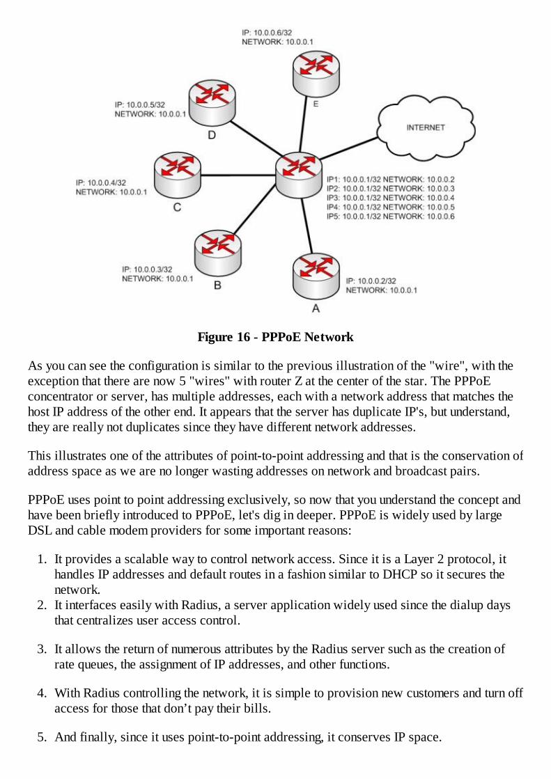
Figure 16 - PPPoE Network
As you can see the configuration is similar to the previous illustration of the "wire", with theexception that there are now 5 "wires" with router Z at the center of the star. The PPPoEconcentrator or server, has multiple addresses, each with a network address that matches thehost IP address of the other end. It appears that the server has duplicate IP's, but understand,they are really not duplicates since they have different network addresses.
This illustrates one of the attributes of point-to-point addressing and that is the conservation ofaddress space as we are no longer wasting addresses on network and broadcast pairs.
PPPoE uses point to point addressing exclusively, so now that you understand the concept andhave been briefly introduced to PPPoE, let's dig in deeper. PPPoE is widely used by largeDSL and cable modem providers for some important reasons:
1. It provides a scalable way to control network access. Since it is a Layer 2 protocol, ithandles IP addresses and default routes in a fashion similar to DHCP so it secures thenetwork.
2. It interfaces easily with Radius, a server application widely used since the dialup daysthat centralizes user access control.
3. It allows the return of numerous attributes by the Radius server such as the creation ofrate queues, the assignment of IP addresses, and other functions.
4. With Radius controlling the network, it is simple to provision new customers and turn offaccess for those that don’t pay their bills.
5. And finally, since it uses point-to-point addressing, it conserves IP space.
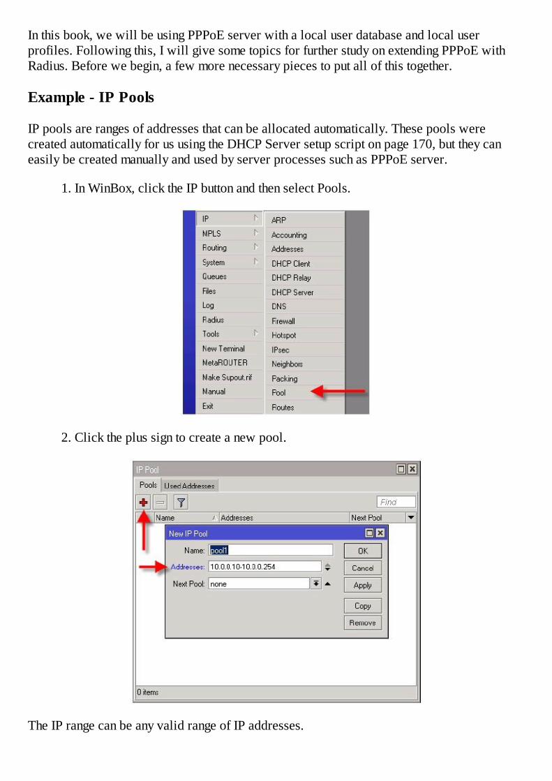
In this book, we will be using PPPoE server with a local user database and local userprofiles. Following this, I will give some topics for further study on extending PPPoE withRadius. Before we begin, a few more necessary pieces to put all of this together.
Example - IP Pools
IP pools are ranges of addresses that can be allocated automatically. These pools werecreated automatically for us using the DHCP Server setup script on page 170, but they caneasily be created manually and used by server processes such as PPPoE server.
1. In WinBox, click the IP button and then select Pools.
2. Click the plus sign to create a new pool.
The IP range can be any valid range of IP addresses.
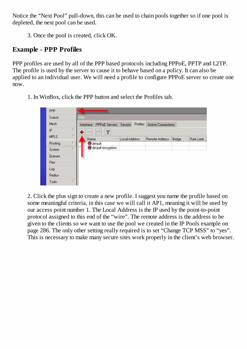
Notice the “Next Pool” pull-down, this can be used to chain pools together so if one pool isdepleted, the next pool can be used.
3. Once the pool is created, click OK.
Example - PPP Profiles
PPP profiles are used by all of the PPP based protocols including PPPoE, PPTP and L2TP.The profile is used by the server to cause it to behave based on a policy. It can also beapplied to an individual user. We will need a profile to configure PPPoE server so create onenow.
1. In WinBox, click the PPP button and select the Profiles tab.
2. Click the plus sign to create a new profile. I suggest you name the profile based onsome meaningful criteria, in this case we will call it AP1, meaning it will be used byour access point number 1. The Local Address is the IP used by the point-to-pointprotocol assigned to this end of the “wire”. The remote address is the address to begiven to the clients so we want to use the pool we created in the IP Pools example onpage 286. The only other setting really required is to set “Change TCP MSS” to “yes”.This is necessary to make many secure sites work properly in the client’s web browser.
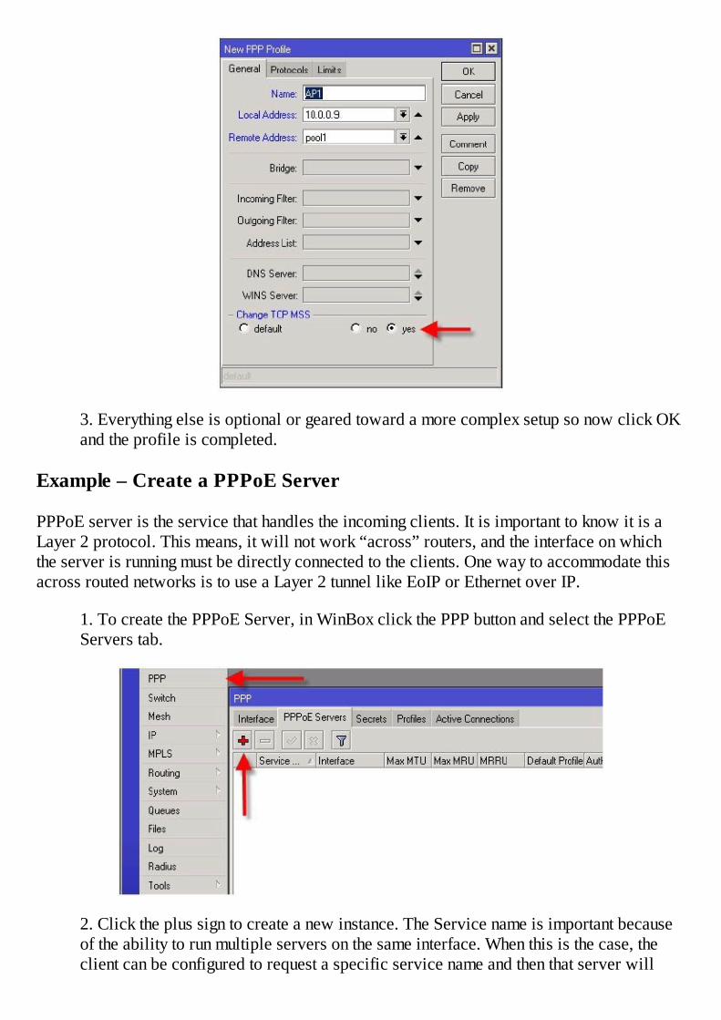
3. Everything else is optional or geared toward a more complex setup so now click OKand the profile is completed.
Example – Create a PPPoE Server
PPPoE server is the service that handles the incoming clients. It is important to know it is aLayer 2 protocol. This means, it will not work “across” routers, and the interface on whichthe server is running must be directly connected to the clients. One way to accommodate thisacross routed networks is to use a Layer 2 tunnel like EoIP or Ethernet over IP.
1. To create the PPPoE Server, in WinBox click the PPP button and select the PPPoEServers tab.
2. Click the plus sign to create a new instance. The Service name is important becauseof the ability to run multiple servers on the same interface. When this is the case, theclient can be configured to request a specific service name and then that server will

answer that client. If no name is specified on the client and if there are multiple servers,there is no control over which one will answer so keep that in mind. Next, set theinterface where it will run. Remember that if you have bridged the physical interface,then the service must run on the bridge so select the bridge instead of the actualinterface.
3. Finally, select the profile created in the previous example on page 288 and then clickOK.
Example – Create a User (Secret)
The final step in the server configuration is the creation of a client user name and passworddone on the secrets tab.
1. On the Secrets tab, click the plus sign. Fill in the name as the user name and assign apassword. I always set the service type because this narrows the scope of the servicesthat can use this secret for authentication.

2. All of the other settings are optional so now click OK.
Example – Create a Client Profile
In the same way that profiles can be applied to servers, they can also be applied to PPPoEclients. Typically, this concept us used to assign a static IP to a PPPoE client or to set a ratelimit. Creating a rate limit will cause a simple queue to be created for the client when theyauthenticate.
1. In WinBox, click the PPP button and select the Profiles tab.
2. Click the plus sign to create a new profile. I like to name the profile based on somemeaningful criteria, in this case we will call it Gold because we have a Gold packagewith the highest speeds and a public IP address as the options. The Local Address is theIP used by the point-to-point protocol to assign to this end of the “wire”. The remote
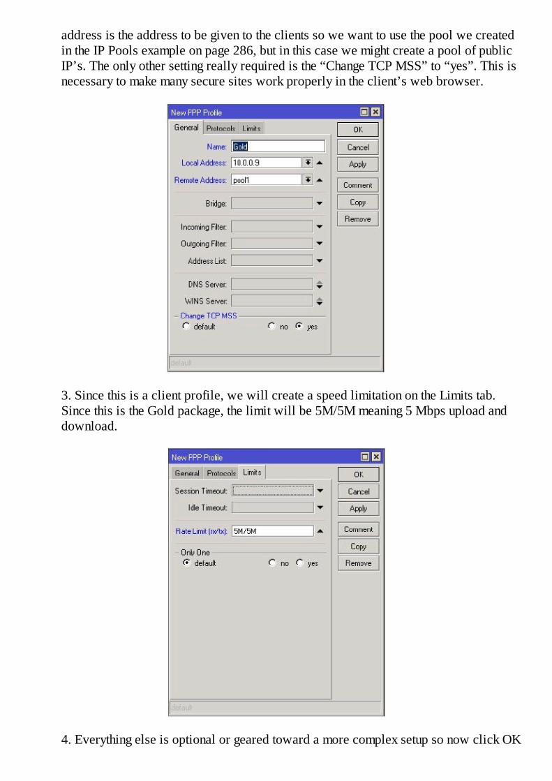
address is the address to be given to the clients so we want to use the pool we createdin the IP Pools example on page 286, but in this case we might create a pool of publicIP’s. The only other setting really required is the “Change TCP MSS” to “yes”. This isnecessary to make many secure sites work properly in the client’s web browser.
3. Since this is a client profile, we will create a speed limitation on the Limits tab.Since this is the Gold package, the limit will be 5M/5M meaning 5 Mbps upload anddownload.
4. Everything else is optional or geared toward a more complex setup so now click OK

and the profile is completed. Back on the secrets tab, assign the profile to any client thatbuys the Gold package.
5. The profile is now completed and may be assigned to one or multiple clients in thesecrets tab.
Example – Create a PPPoE Client
With the server configured, we need a client and RouterOS provides that as well. Rememberthat since RouterOS is standards based, any PPPoE client should work with a RouterOSPPPoE server. To create a PPPoE client:
1. In WinBox, click the PPP button and in the list select PPPoE Client.
2. The Name is optional, but you will need to select the Interface on the General tab.Remember, this is a Layer 2 protocol so it needs to know where to look for the server.

3. On the Dial Out tab, you can select a service name to match the server’s servicename or leave blank for any service. Next, add the User and Password and you willlikely want to Use Peer DNS so check that box as well.
4. Click ok, and the client should immediately negotiate a connection to the server.
PPTP and L2TP Tunnels
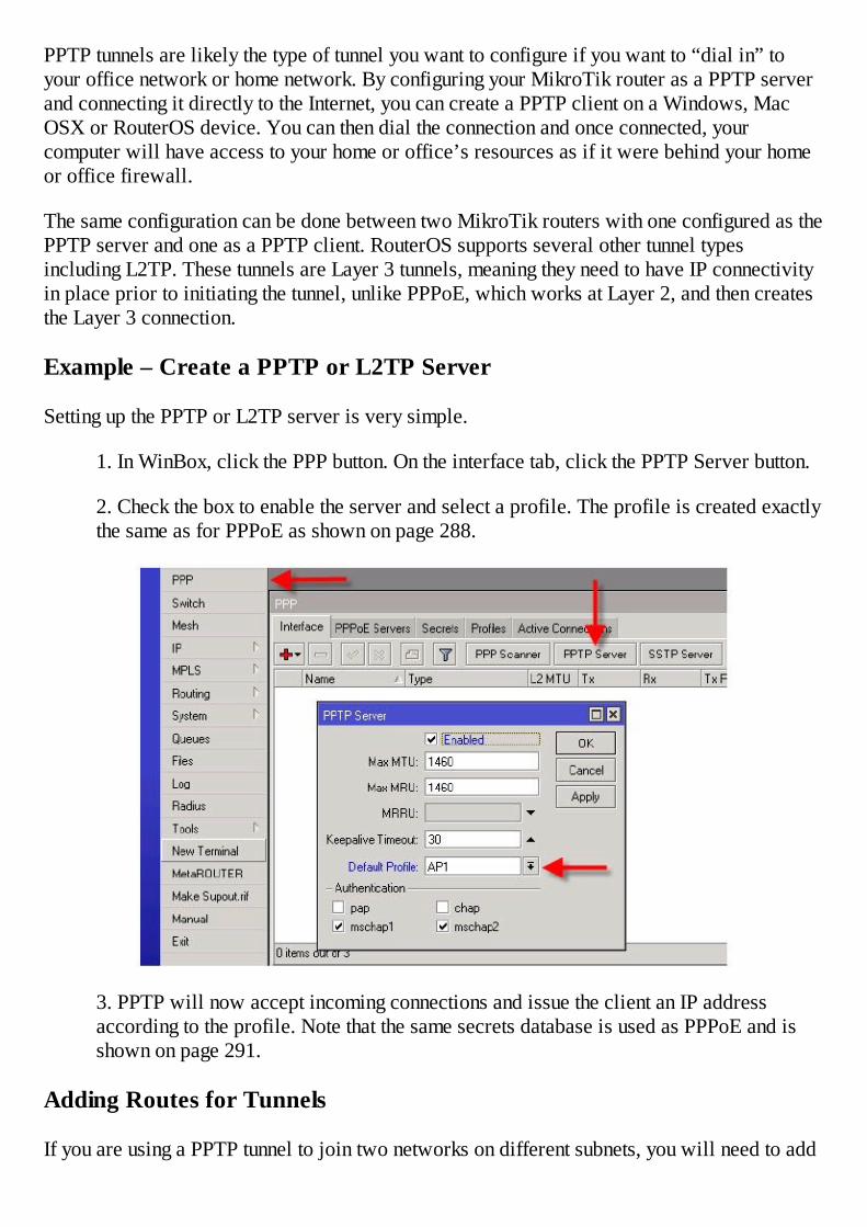
PPTP tunnels are likely the type of tunnel you want to configure if you want to “dial in” toyour office network or home network. By configuring your MikroTik router as a PPTP serverand connecting it directly to the Internet, you can create a PPTP client on a Windows, MacOSX or RouterOS device. You can then dial the connection and once connected, yourcomputer will have access to your home or office’s resources as if it were behind your homeor office firewall.
The same configuration can be done between two MikroTik routers with one configured as thePPTP server and one as a PPTP client. RouterOS supports several other tunnel typesincluding L2TP. These tunnels are Layer 3 tunnels, meaning they need to have IP connectivityin place prior to initiating the tunnel, unlike PPPoE, which works at Layer 2, and then createsthe Layer 3 connection.
Example – Create a PPTP or L2TP Server
Setting up the PPTP or L2TP server is very simple.
1. In WinBox, click the PPP button. On the interface tab, click the PPTP Server button.
2. Check the box to enable the server and select a profile. The profile is created exactlythe same as for PPPoE as shown on page 288.
3. PPTP will now accept incoming connections and issue the client an IP addressaccording to the profile. Note that the same secrets database is used as PPPoE and isshown on page 291.
Adding Routes for Tunnels
If you are using a PPTP tunnel to join two networks on different subnets, you will need to add

routes to each router pointing to the other router’s subnet. For example, for a PPTP client, thedestination network will be the subnet at the far end of the tunnel and the gateway will be theIP address of the PPTP server contained in the server’s PPTP profile as the Local IP. For theserver end of the tunnel, the destination network will be the remote client’s subnet and thegateway IP address will be the PPTP client’s tunnel IP.
Tunnels With IP Addresses on Same Subnet as LAN Hosts
This is the remote end tunnel and the remote LAN is 192.168.1.0/24:
This is the server end tunnel and the server LAN is 192.168.0.0/24:
On the remote end add this route:
Destination: 192.168.0.0/24 and Gateway: 10.10.10.1
On the Server end add this route:
Destination: 192.168.1.0/24 and Gateway: 10.10.10.2

This will allow the two LAN subnets to be able to reach one another through the tunnel.
Note that if you assign your PPTP clients IP addresses from the same subnet as your PPTPserver’s local area network, you will need to enable proxy-arp on the interface facing yourlocal area network clients. Proxy-arp transmits the MAC of all connected hosts so that thePPTP server will ARP for the remote client, thereby enabling LAN hosts to communicate withit.
Configuring L2TP Server
To configure L2TP, follow the exact same steps as for the PPTP server, except perform theconfiguration using the L2TP button on the PPP Interface tab.
PPP Status Tab
The PPP Status tab shows the status of any clients that may be connected to the router’s PPPservices. The clients IP address, user name, and connection time is displayed for each client.
Bridging Tunnels

Thus far we have explored three tunnel types, PPPoE, PPTP and L2TP. All three are Layer 3routed tunnels, but it is also possible to create tunnels that can be bridged. Bridged tunnelswork just like any bridge, that is, packets that enter a bridge port are transmitted out the otherbridge ports. Bridges join dissimilar interfaces into a single logical interface.
Two types of tunnels that can bridge networks are EoIP (Ethernet Over IP), and VPLS (VirtualPrivate LAN Service). EoIP is simpler to create but has increased overhead over VPLS.
Example – Create a Bridged EoIP Tunnel
1. In WinBox, click the Interfaces button and select a new EoIP tunnel interface. Theonly information that is mandatory is the Remote IP Address of the other end of thetunnel. If tunneling across the Internet, this will be the public IP address of the remotehost. The tunnel ID must be unique for every tunnel on the router so use the default orchange if adding multiples.
2. Click OK.
3. Repeat the process on the remote end of the tunnel.
Once the tunnel is running, evidenced by the letter “R” next to the interface, you can bridge itto other physical interfaces. For example, if your LAN is on ether1 on both ends of the tunnel,create a new bridge interface by clicking the Bridge button and the plus sign.

On the ports tab add ether1 and the EoIP tunnel you just created. Repeat on the remote end ofthe link and your two networks will be joined at Layer 2.
Example – Create a Transparent VPLS Tunnel
The routing and MPLS packages are required to create a transparent VPLS tunnel. Thisexample assumes you are connecting two hosts with a VPLS tunnel in order to bridge twowireless devices together without using EoIP or station-wds mode.
It is also assumed that you have an existing wireless connection between the two devices, thatis, one device is in ap-bridge or bridge mode and the other device is in station mode and isassociated with the access point. This can be done as demonstrated on page 238.
MPLS also requires Layer 3 connectivity between the two devices, so you will need an IPaddress on the wireless interface on the AP device and an IP address on the same subnet onthe wireless interface on the station device. Adding IP addresses is covered on page 37. Thetwo hosts should be able to ping each other.
In this example, we are assuming that the AP has an IP address of 10.0.0.1/24 on the wlan1interface and that the station is associated wirelessly with the AP and has an IP address of10.0.0.2/24 on its wlan1 interface.
Near End of Tunnel (AP)
1. In WinBox, begin by clicking the MPLS button. First you must turn LDP on byclicking the LDP Settings button and enabling LDP.

2. On the LDP tab click the plus sign. Select the interface on which we will create thetunnel, in this case wlan1 and the transport IP address which is the wlan1 IP of thisrouter, 10.0.0.1 and click OK.
3. In WinBox, click the MPLS button and select the VPLS submenu button and on theVPLS tab click the plus sign. Set the Remote Peer to the IP address of the remote end’swlan1 interface, in this example, 10.0.0.2. Set the VPLS ID to the default of 0:0 andclick OK.
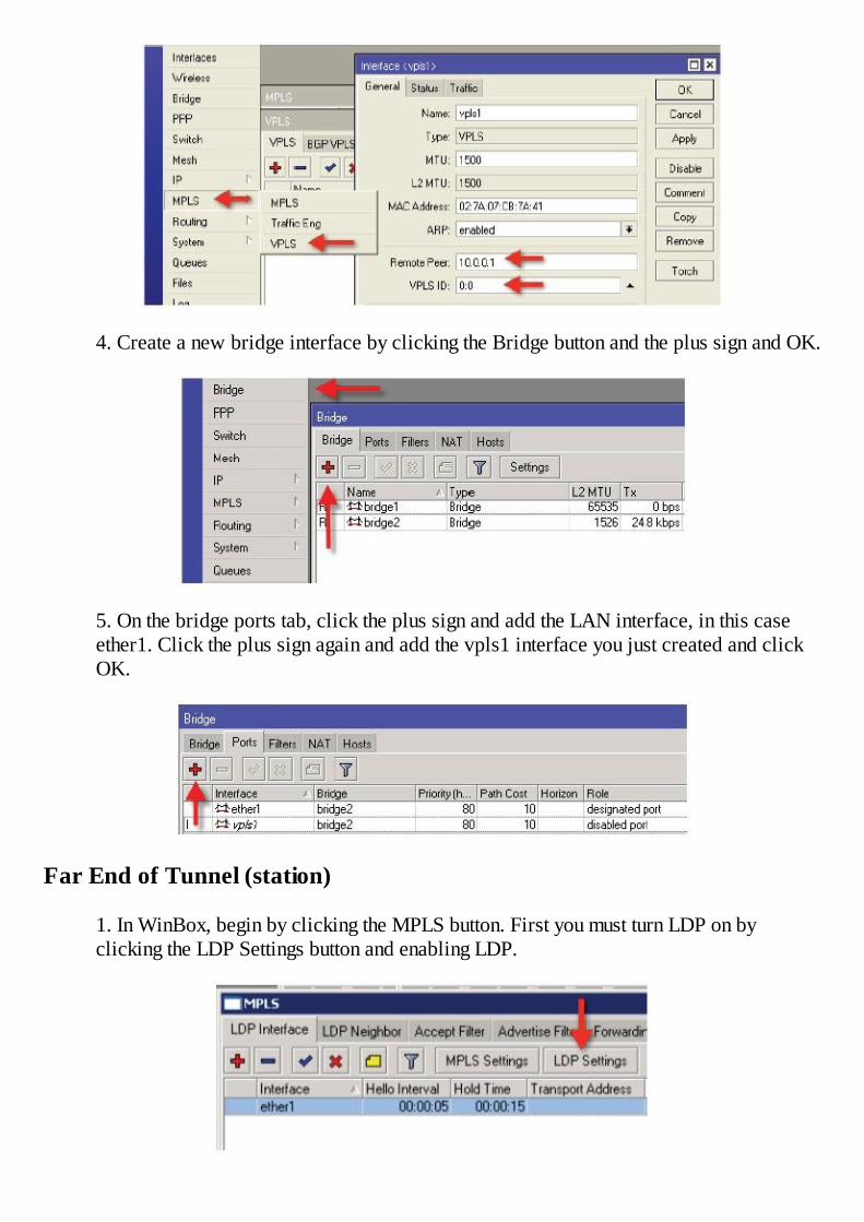
4. Create a new bridge interface by clicking the Bridge button and the plus sign and OK.
5. On the bridge ports tab, click the plus sign and add the LAN interface, in this caseether1. Click the plus sign again and add the vpls1 interface you just created and clickOK.
Far End of Tunnel (station)
1. In WinBox, begin by clicking the MPLS button. First you must turn LDP on byclicking the LDP Settings button and enabling LDP.
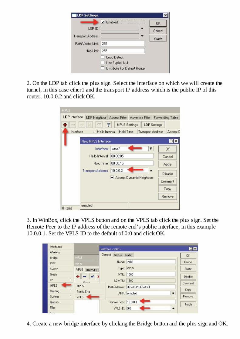
2. On the LDP tab click the plus sign. Select the interface on which we will create thetunnel, in this case ether1 and the transport IP address which is the public IP of thisrouter, 10.0.0.2 and click OK.
3. In WinBox, click the VPLS button and on the VPLS tab click the plus sign. Set theRemote Peer to the IP address of the remote end’s public interface, in this example10.0.0.1. Set the VPLS ID to the default of 0:0 and click OK.
4. Create a new bridge interface by clicking the Bridge button and the plus sign and OK.
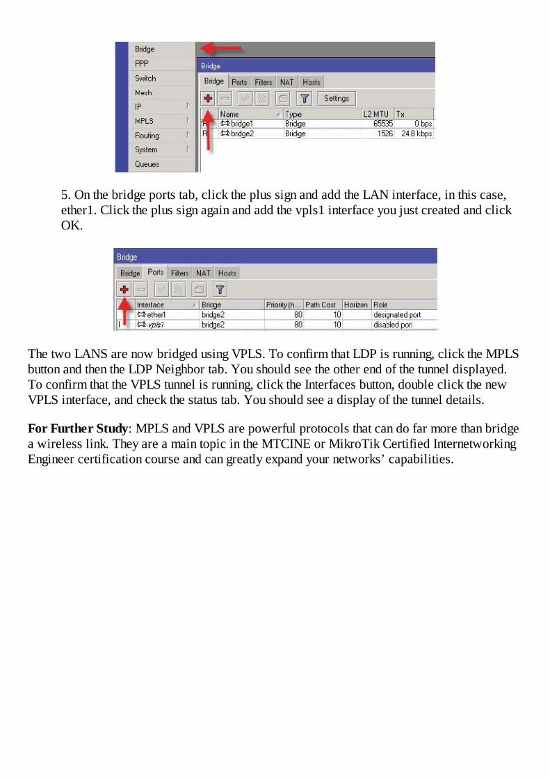
5. On the bridge ports tab, click the plus sign and add the LAN interface, in this case,ether1. Click the plus sign again and add the vpls1 interface you just created and clickOK.
The two LANS are now bridged using VPLS. To confirm that LDP is running, click the MPLSbutton and then the LDP Neighbor tab. You should see the other end of the tunnel displayed.To confirm that the VPLS tunnel is running, click the Interfaces button, double click the newVPLS interface, and check the status tab. You should see a display of the tunnel details.
For Further Study: MPLS and VPLS are powerful protocols that can do far more than bridgea wireless link. They are a main topic in the MTCINE or MikroTik Certified InternetworkingEngineer certification course and can greatly expand your networks’ capabilities.


Chapter 18 - Conclusion
I hope that you have enjoyed this book and have learned the concepts presented through myexamples. RouterOS is a powerful routing system with many configurable options andcapabilities. Fully learning it requires both book knowledge and hands on experience.Through study, practice, trial and error, you will learn to master this powerful tool.
After some time and experience using the basics presented in this book, you should challengeyourself by obtaining a MikroTik Certified Network Associate certificate. When you arecomfortable with all of the concepts learned in the MTCNA course, you should obtain one ormore advanced certifications to further explore this powerful operating system.
Writing a technical book with many similar sounding acronyms is a real challenge. Withprotocols like PPP, PPTP, PPPoE, L2TP and the like, it is easy to make a mistake no matterhow many times your work is proof read. For this reason, I invite you to email any errors youmay find to [email protected]. I welcome your corrections and suggestions and willincorporate them as well as any updates in future printings. These corrections and updates canalso be found at http://learnmikrotik.com/book/corrections. You may also sign up for emailnotifications of updates at the same web site.
Thank you for reading my book and I hope to see you in one of my classes soon!
Steve Discher http://www.LearnMikroTik.com


References
1. © MikroTik, www.mikrotik.com. All rights reserved. Reprinted with permission as usedfor training.
2. E.W. Dijkstra. “A Note on Two Problems in Connection with Graphs.” NumerischeMathematic 1:269-271, 1959.
3. Stephen A. Thomas. “IP Switching and Routing Essentials.” Wiley Computer Publishing103, 2002.
4. “Traceroute.” Wikipedia, The Free Encyclopedia. Wikimedia Foundation, Inc. Web, 22September 2011.


Appendix 1
Official MikroTik Certified Network Associate Training Syllabus
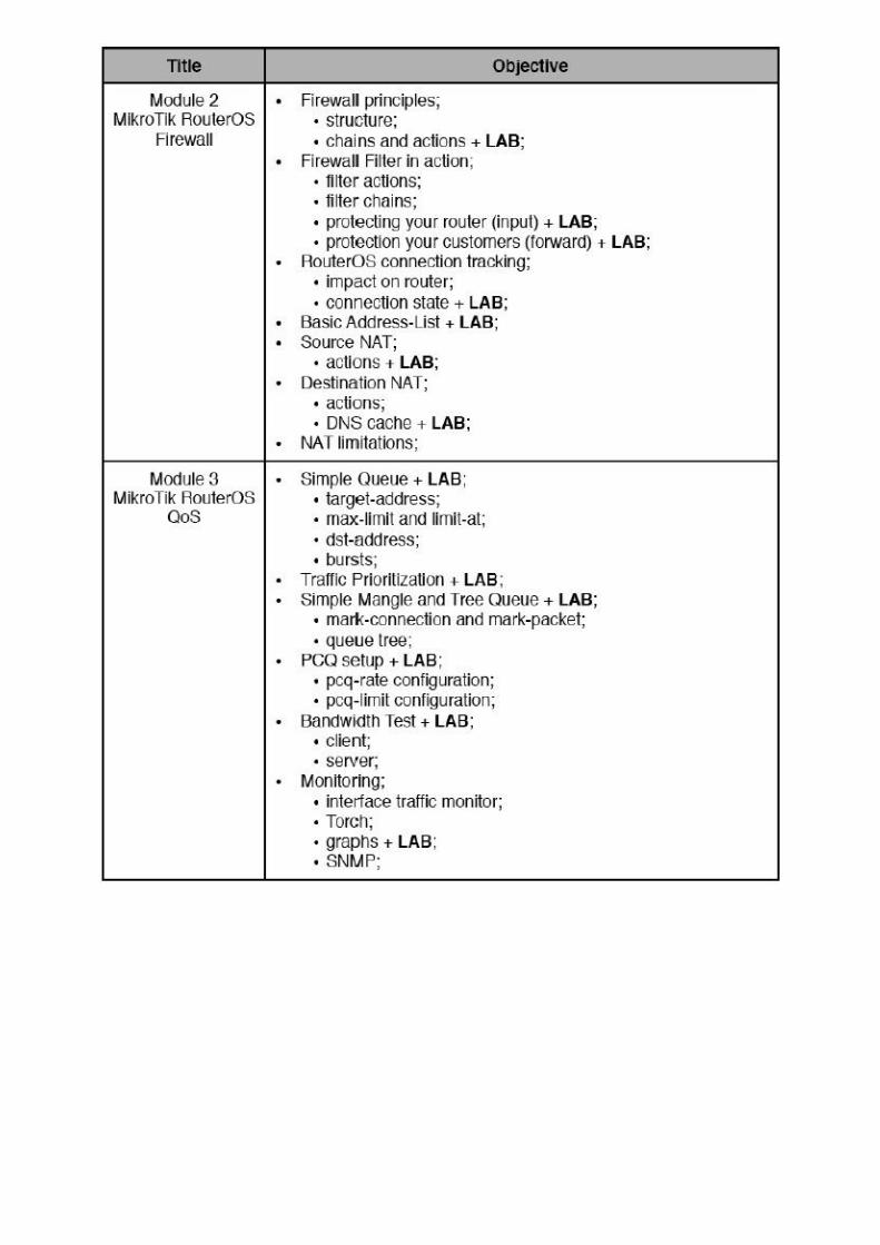
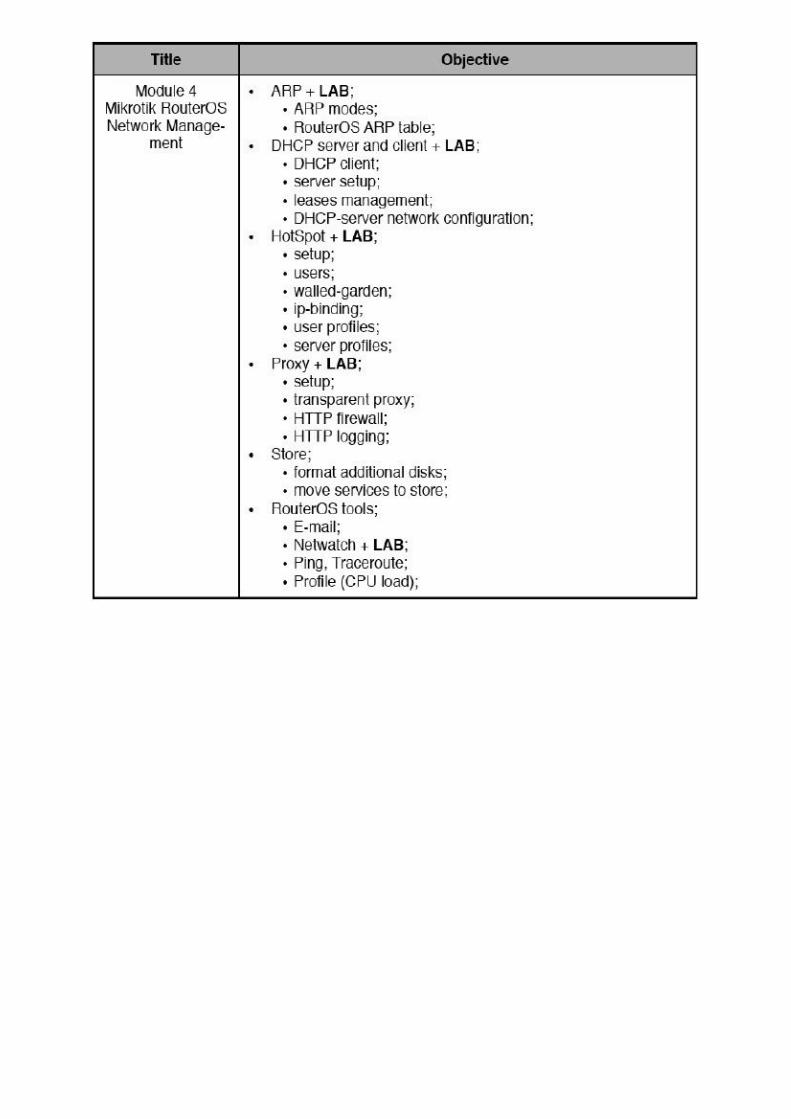


Table of Figures
Figure 1 - IP Firewall Input Chain 1
Figure 2 – Connections 1
Figure 3 - Source NAT 1
Figure 4 - Packet Flow Diagram 1
Figure 5 - Conn Track On/Off 1
Figure 6 - PCQ Behavior 1
Figure 7 - PCQ Behavior 1
Figure 8 - Bandwidth Test Layout.
Figure 9 - 802.11 b/g Channels, 2.4 GHz 1
Figure 10 - 5.8 GHz Channels
Figure 11 - Application Matrix by Protocol 1
Figure 12 - Routing Diagram
Figure 13 - Routing Diagram
Figure 14 - OSPF Network
Figure 15 - Point to Point Addressing
Figure 16 - PPPoE Network

Index
8
802.11
802.11a
802.11b
802.11g
802.11n
A
Access List
Access Lists
Add an IP Address
Adding a Package
Address Lists
Areas
ARP
B
Backups
Bandwidth Test Utility
Basic Firewall
Blocking Certain Sites
boot loader
Bridged
Bridging
Bridging a Link

Bridging an access point
Burst
C
channel width
Channelization
Clock
Connect Lists
Connection Tracking
Connections
Custom Login Page
D
Default Routes
Destination NAT
Destination NAT with Action Redirect
Destination NAT with the Action Redirect
DHCP
DHCP Client
DHCP Server
Disable Connection Tracking
DNS
Downgrading
Dynamic Routes
E
Encryption
EoIP

F
Firewalls
Forgotten Password
Forward Chain
H
Hiding the SSID
Hotspot
Http Firewall
I
Importing a Text Backup
input chain
Install a License
Interfaces
interference
IP Bindings
IP Pools
L
L2TP
License Level
license levels
Licensing
Link State Protocol
Local Area Networks
Logging to a Remote Syslog Server
Logging Web Traffic

M
MAC Filtering
Masquerade
Monitoring Tools
Most Specific Route
N
NAT, Network Address Translation
NetInstall
Netwatch
NTP
NTP Client
NTP Server
NV2
O
One Limit to All
Optimum Mangle
OSPF
P
Package Management
PCQ – Per Connection Queuing
Ping
Point to Point Addressing
Point to Point Links
PPP Profiles
PPP Status
PPPoE Client
PPPoE Server
PPTP
Profile
Proprietary Protocols
Pseudobridge
Q
Queue Priority for VOIP Traffic
R
Redirect
Restoring a Binary Backup
Route Distance
Routed
Router Identity
Routing
Routing Flags
S
Secret
Serial Terminal
Server Profiles
Service Ports
Simple Queue
Simple Queues
Small Channels
SNMP

Source NAT
Source NAT to Source Traffic From a Certain IP Address,
Source NAT With Multiple Public IP Addresses
Static ARP
Static Leases
Static Routes
Station - pseudobridge - clone
Storage
Stores
System Identity
System Time
T
Text Export
Tools
Traceroute
Traffic Graphing
Traffic Prioritization
Transparent Web Proxy
U
Upgrading
Upgrading using FTP
User and Group Assignments
User Management
User Profiles
UserManager

V
Virtual AP
VOIP
VPLS,
VPN Tunnels
W
Walled Garden
WDS
Web Proxy
WEP
WinBox
Wireless
Wireless Distribution System
Wireless Security
Wireless Theory
WPA
WPA2