ROUND STORAGE SILO -...
24
ARSKAMETALLI LTD www.arskametalli.fi A70-1001-EN-201805 ROUND STORAGE SILO Ø480cm, Ø560cm, Ø640cm, Ø720cm ASSEMBLY AND USER MANUAL
Transcript of ROUND STORAGE SILO -...

ARSKAMETALLI LTDwww.arskametalli.fi
A70-1001-EN-201805
ROUND STORAGE SILOØ480cm, Ø560cm, Ø640cm, Ø720cm
ASSEMBLY AND USER MANUAL

2 | A70-1001-EN-201805 | Arskametalli Ltd
IntroductionDelivery informationEU Declaration of ConformitySafety
1. Overview1.1. Dimensions1.2. Delivery contents1.3. Unpacking1.4. Foundation 1.4.1. List of rebars1.5. Lifting the silo 1.5.1. Lift brackets (when over 10 layers)1.6. Wall element thickness, reinforcements, extensions and base supports
2. Assembly2.1. Roof and two top layers2.2. Roof ladder, railings and wall ladder2.3. Remaining layers and reinforcements 2.3.1. Manhole 2.3.2. Wall outlet for auger2.4. Attaching to foundation2.5. Finishing
3. Filling and discharging
4. Options
34 56
78
10101010111112
1414161718181920
21
22
CONTENTS

Arskametalli Ltd | A70-1001-EN-201805 | 3
INTRODUCTIONProduction facilities of Arskametalli Ltd are located in Somero, Southwest Finland. The family company has been operating for three generations and has manufactured grain handling equipment already since 1958.
Arskametalli Ltd has been granted CE marking for structural welded steel assemblies and product systems as well as for internal quality control. Operations are based on the SFS-EN ISO 9001 quality system and for load-bearing structures to meet SFS-EN ISO 3834-3 welding requirements. In operations the essential requirements of the SFS-EN ISO 14001 environmental and OHSAS 18001 safety management system are taken into account.
This manual describes the assembly and operating instructions of the Arska round storage silo. Read this entire manual before installing the product. See the operating instructions and the necessary safety instructions. Successful installation and pre-trained use ensure functional operations.
Keep this manual available for frequent reference and review it with new personnel.
If you need any additional information or assistance, please contact your distributor or us(www.arskametalli.fi).

4 | A70-1001-EN-201805 | Arskametalli Ltd
DELIVERY INFORMATION
Inspection of goods
Check that the number of packages matches the packing list and that the package and the items are intact. Mark any damages and missing materials on the packing list and report to the transport company and Arskametalli. Do not install any faulty or incorrect materials.
Warranty
All round storage silos manufactured by Arskametalli receive a 5-year factory warranty starting from the date of delivery.
The warranty requires that owner of the product makes a announcement and a warranty application immediately after broke directly to manufacturer. If the faulted part and the warranty application haven’t been delivered to warranty check to the manufacturer within two weeks of breaking, it won’t be dealed as a warranty issue. The manufacturer is not responsible of additional warranty given by distributor.
The warranty requires that during the assembly there has been followed valid orders and manufacturer’s instructions. Warranty covers production and material faults. Warranty does not cover faults caused by wrong assembly, improper using or neglecting the maintenance.

Arskametalli Ltd | A70-1001-EN-201805 | 5
EC DECLARATION OF CONFORMITYManufacturer:Arskametalli LtdSaarentaantie 33FI-31400 Somero, Finland
Product: Arska round storage siloDiameter: Ø480cm, Ø560cm, Ø640cm, Ø720cm
We hereby declare that the product complies with the directives:• 2006/42/EY Machinery Directive• 2006/95/EY Low Voltage Directive• 2004/108/EY Electromagnetic Compatibility Directive (EMC)
Harmonized standards that have been used:• SFS-EN 349 + A1• SFS-EN ISO 12100• SFS-EN ISO 13857• SFS-EN 60204-1:2006
Somero 15.1.2010
Janne Käkönen, CEO

6 | A70-1001-EN-201805 | Arskametalli Ltd
SAFETYThe product must be installed by a person who is suitably qualified. During assembly work follow valid safety orders.
Use the product only for it’s intended purpose. Do not modify the product in any way. Unauthorised modifications may impair the functionality and safety and affect the product’s service life. Any modification of the product voids the warranty.
Assembly done wrong can lead to personal injuries or cause damage to the product. Incorrectly installed product may not work right and the capacity may drop. Read this manual carefully well before starting the assembly, maintaining or using.
General information
• Avoid lifting at windy weather. The lift must go straight.• Install racks under the silo’s hem immediately after the lifting.• Do not use the silo if hatches and covers haven’t been installed.• Always use appropriate tools, classified lifting equipment and cranes at work.• Make sure that the railings are properly installed and that they are in good condition.• Do not use, assemble or maintain the product alone.• Keep first aid kit available at all times.• Make sure that the working area is clean, dry and well lit.• Make sure that the person responsible of using the product has acquainted to it’s functions
and safety orders.• Packaging must be disposed properly.
Personal safety
Always wear protective equipment when assembling or using the silo.
Signal words
! NOTE!The note text contains information that makes the installing easier.
! CAUTION!If caution text instructions are not followed, the product may be damaged. It can also result in incorrect operation or capacity decrease.
! WARNING!If warning text instructions are not followed, it could result in serious or life-threatening injuries.
Arskametalli Ltd | A70-1001-EN-201805 | 7
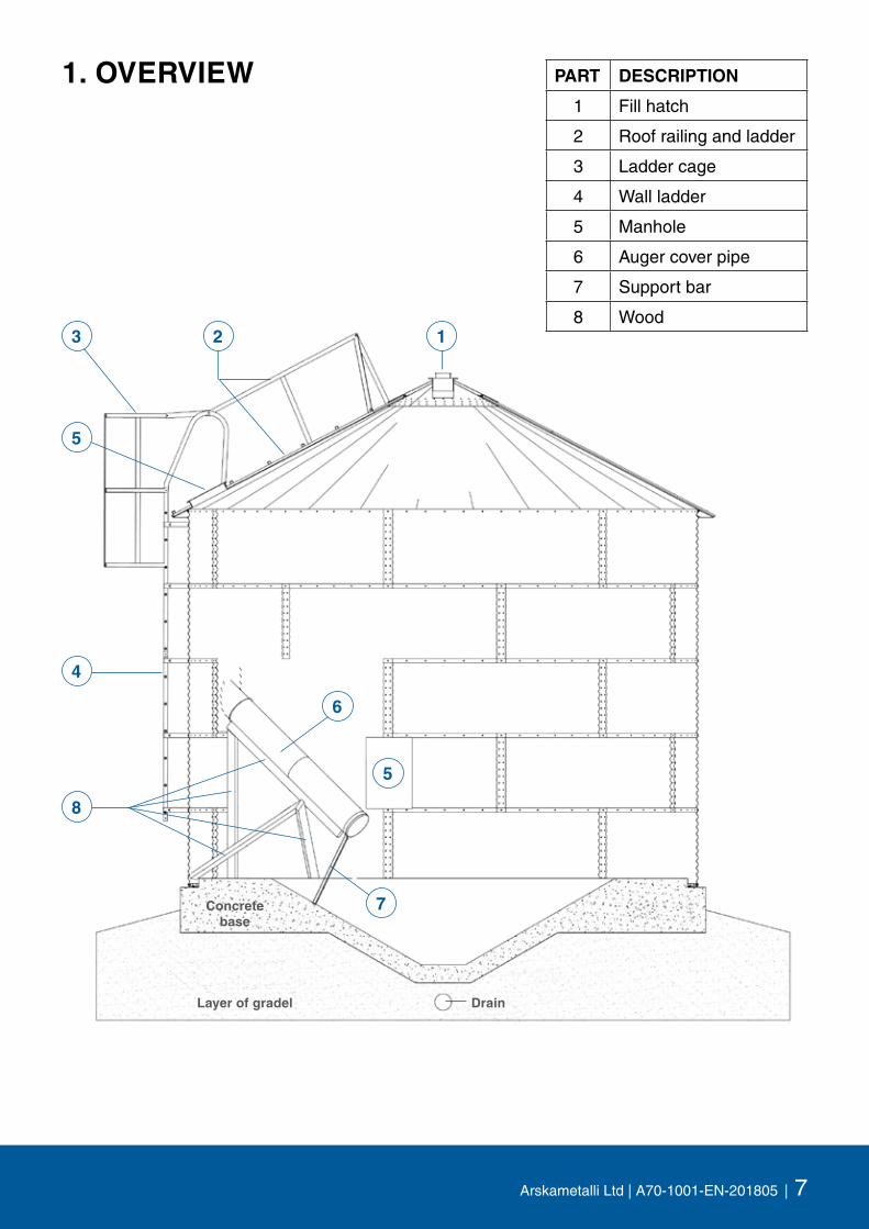
1. OVERVIEW PART DESCRIPTION
1 Fill hatch
2 Roof railing and ladder
3 Ladder cage
4 Wall ladder
5 Manhole
6 Auger cover pipe
7 Support bar
8 Wood
Concrete base
DrainLayer of gradel
4
5
6
8
1
5
7
23

8 | A70-1001-EN-201805 | Arskametalli Ltd
1.1. DimensionsA
C
825
B
235
315

Arskametalli Ltd | A70-1001-EN-201805 | 9
Ø / LAYER VOLUME [m3] A [mm] B [mm] A + B [mm] C [mm] WEIGHT [kg]
4,8m / 4 68 3 360 1 200 4 560 4 800 1 040
4,8m / 5 84 4 200 1 200 5 400 4 800 1 240
4,8m / 6 100 5 030 1 200 6 230 4 800 1 440
4,8m / 7 116 5 870 1 200 7 070 4 800 1 640
4,8m / 8 132 6 710 1 200 7 910 4 800 1 840
4,8m / 9 148 7 550 1 200 8 750 4 800 2 040
4,8m / 10 164 8 390 1 200 9 590 4 800 2 240
Ø / LAYER VOLUME [m3] A [mm] B [mm] A + B [mm] C [mm] WEIGHT [kg]
5,6m / 4 96 3 360 1 400 4 760 5 600 1 340
5,6m / 5 117 4 200 1 400 5 600 5 600 1 570
5,6m / 6 138 5 030 1 400 6 430 5 600 1 800
5,6m / 7 159 5 870 1 400 7 270 5 600 2 050
5,6m / 8 180 6 710 1 400 8 110 5 600 2 310
5,6m / 9 101 7 550 1 400 8 950 5 600 2 540
5,6m / 10 122 8 390 1 400 9 790 5 600 2 770
Ø / LAYER VOLUME [m3] A [mm] B [mm] A + B [mm] C [mm] WEIGHT [kg]
6,4m / 4 124 3 360 1 600 4 960 6 400 1 640
6,4m / 5 151 4 200 1 600 5 800 6 400 1 900
6,4m / 6 178 5 030 1 600 6 630 6 400 2 160
6,4m / 7 205 5 870 1 600 7 470 6 400 2 420
6,4m / 8 232 6 710 1 600 8 310 6 400 2 680
6,4m / 9 259 7 550 1 600 9 150 6 400 2 940
6,4m / 10 286 8 390 1 600 9 990 6 400 3 200
Ø / LAYER VOLUME [m3] A [mm] B [mm] A + B [mm] C [mm] WEIGHT [kg]
7,2m / 4 156 3 360 1 800 5 160 7 200 1 940
7,2m / 5 190 4 200 1 800 6 000 7 200 2 230
7,2m / 6 224 5 030 1 800 6 830 7 200 2 520
7,2m / 7 258 5 870 1 800 7 670 7 200 2 810
7,2m / 8 292 6 710 1 800 8 510 7 200 3 100
7,2m / 9 326 7 550 1 800 9 350 7 200 3 390
7,2m / 10 360 8 390 1 800 10 190 7 200 3 680

10 | A70-1001-EN-201805 | Arskametalli Ltd
1.2. Delivery contents
• Wall elements, one with a manhole• Roof sections, one with a manhole• Top cone and rain cover• Wall outlet, cover pipe and cover hood for the discharge auger• Wall ladder (back support if needed) and roof ladder with railings• Reinforcements and base parts (attaching to foundation)• Butyl mass, sealant extruder, screws, nuts, washers, variety of fasteners
1.3. Unpacking
Unpack the package if you can’t start the assembly straight away. The storing area has to be dry. Place the wall elements such that the air flows between them. This is to prevent the so called white rust from emergencing. You don’t have to unpack the screw packages. Store the sealant to a warm place.
1.4. Foundation
The silo is filled straight from the grain dryer (foundation close to the elevator) or using a conveyor. Check the need for the permission from your local building authority.
The silo requires strong and frost resistant foundation. Pay attention to the drainage in order to avoid moisture damage. The foundation is made according to the separate structure drawings. You can get the drawings for flat and cone bases from the manufacturer.
1.4.1. List of rebars
Rebars have been calculated with a 0,5m overlap / 6m.
CONE BASES FLAT BASES
Ø4,8 Ø5,6 Ø6,4 Ø7,2 Ø4,8 Ø5,6 Ø6,4 Ø7,2
Rebar 6mm [m] 125 192 239 267 91 103 118 131
Rebar 10mm [m] 603 815 1 005 1 242 585 791 1 021 1 276
Concrete [m3] 9,5 12,5 15,5 18,5 6,5 8,5 10,5 12,5
Concrete + 10% [m3] 11 14 17 21 5 9 12 14

Arskametalli Ltd | A70-1001-EN-201805 | 11
1.5. Lifting the silo
The silo can be lifted from the top cone or from the lifting brackets which are attached to the roof and the wall elements. You can lift max. 10 layers high silos from the top cone.
When lifting from the top cone you need a Ø500mm disc which shares the load evenly to the perimeter of the cone. Thread the lifting chain inside from the fill hatch and attach it to the disc.
1.5.1. Lift brackets (when over 10 layers)
Lifting brackets (4 pcs) are used when you have to lift over 10 layers high silos. Lifting brackets are put together of two parts, of a fastener and and a bracket. Install the brackets symmetrically to silo’s perimeter such that the lifting chains can be same at length. The chain angle between a single chain and the horizontal level is minimum of 60 degrees.
Install the first bracket where the wall element’s vertical seam touches the center of the roof section. Install the fastener to the vertical seam with the highest screws. Attach the bracket to the fastener using the middle screw of the roof section. Drill holes to the section to the outermost holes of the bracket and attach the parts to each other with M10x30 screws and nuts.
Install the remaining bracket-fastener pairs such that they come to the middle of the roofsection. Drill holes to the wall elements for the fastener screws and to the roof sectionsthe outermost holes of the brackets.
Bracket
Fastener

12 | A70-1001-EN-201805 | Arskametalli Ltd
1.6. Wall element thickness, reinforcements, extensions and base supports
Ø5,6m LOW
ES
T
LAY
ER
2. 3. 4. 5. 6. 7. 8. 9. 10.REINF.[pcs]
EXT.[pcs]
BASESUPPORT
[pcs]4 layers 1,5 1,5 1,25 1,25 - - - - - - 14 0 145 layers 1,5 1,5 1,5 1,25 1,25 - - - - - 14 0 146 layers 1,5 1,5 1,5 1,5 1,25 1,25 - - - - 14 0 147 layers 1,5 1,5 1,5 1,5 1,5 1,25 1,25 - - - 28 14 148 layers 1,5 1,5 1,5 1,5 1,5 1,5 1,25 1,25 - - 28 14 149 layers 1,5 1,5 1,5 1,5 1,5 1,5 1,5 1,25 1,25 - 42 28 1410 layers 1,5 1,5 1,5 1,5 1,5 1,5 1,5 1,5 1,25 1,25 42 28 14
Ø4,8m LOW
ES
T
LAY
ER
2. 3. 4. 5. 6. 7. 8. 9. 10.REINF.[pcs]
EXT.[pcs]
BASESUPPORT
[pcs]4 layers 1,5 1,5 1,25 1,25 - - - - - - 12 0 125 layers 1,5 1,5 1,5 1,25 1,25 - - - - - 12 0 126 layers 1,5 1,5 1,5 1,5 1,25 1,25 - - - - 12 0 127 layers 1,5 1,5 1,5 1,5 1,5 1,25 1,25 - - - 24 12 128 layers 1,5 1,5 1,5 1,5 1,5 1,5 1,25 1,25 - - 24 12 129 layers 1,5 1,5 1,5 1,5 1,5 1,5 1,5 1,25 1,25 - 36 24 1210 layers 1,5 1,5 1,5 1,5 1,5 1,5 1,5 1,5 1,25 1,25 36 24 12
Ø6,4m LOW
ES
T
LAY
ER
2. 3. 4. 5. 6. 7. 8. 9. 10.REINF.[pcs]
EXT.[pcs]
BASESUPPORT
[pcs]4 layers 1,5 1,5 1,25 1,25 - - - - - - 16 0 165 layers 1,5 1,5 1,5 1,25 1,25 - - - - - 16 0 166 layers 1,5 1,5 1,5 1,5 1,25 1,25 - - - - 32 16 167 layers 1,5 1,5 1,5 1,5 1,5 1,25 1,25 - - - 32 16 168 layers 1,5 1,5 1,5 1,5 1,5 1,5 1,25 1,25 - - 48 32 169 layers 1,5 1,5 1,5 1,5 1,5 1,5 1,5 1,25 1,25 - 48 32 1610 layers 1,5 1,5 1,5 1,5 1,5 1,5 1,5 1,5 1,25 1,25 64 48 16
Ø7,2m LOW
ES
T
LAY
ER
2. 3. 4. 5. 6. 7. 8. 9. 10.REINF.[pcs]
EXT.[pcs]
BASESUPPORT
[pcs]4 layers 1,5 1,5 1,5 1,25 - - - - - - 18 0 185 layers 1,5 1,5 1,5 1,5 1,25 - - - - - 36 18 186 layers 1,5 1,5 1,5 1,5 1,5 1,25 - - - - 36 18 187 layers 1,5 1,5 1,5 1,5 1,5 1,5 1,25 - - - 54 36 188 layers 1,5 1,5 1,5 1,5 1,5 1,5 1,5 1,25 - - 54 36 189 layers 1,5 1,5 1,5 1,5 1,5 1,5 1,5 1,5 1,25 - 72 54 1810 layers 1,5 1,5 1,5 1,5 1,5 1,5 1,5 1,5 1,5 1,25 72 54 18
REINFORCEMENTS

Arskametalli Ltd | A70-1001-EN-201805 | 13
1655
220
340
Extension
Extension
Extension
Base support
Base support
Reinforcement
Reinforcement
Reinforcement
Reinforcement

14 | A70-1001-EN-201805 | Arskametalli Ltd
! CAUTION!Assemble the wall elements by inserting the higher element to the outside of the lower element. This is to avoid the rain water getting into the silo.
Attach wall elements to each other with M10x20 bolts and nuts (remember washer). Seal vertical seams from the outside of the hole row. Seal horizontal seams by extruding the mass above the higher hole row (red markings on picture).
2. ASSEMBLYMake sure you have enough of room during assembly. Note the space required for installing rooflists. Pneumatic and battery powered tools save time and make the job smoother. Book two conical ended mounting hardware (centre punches) for each person. Sturdy racks will expedite the work and prevent damage.
We recommend to assemble silo using the so-called ”up-to-down” method with a crane. This manual is made according to this method. The crane should be big and extending enough so that the lifting and working are safe.
Use butyl mass for sealing. Carefully done sealing ensures that the silo fills the requirements. Release the sealant extruder from pressure every time you stop sealing.
The wall elements are made of galvanized steel. The color ID of material thickness is painted inside the wall element, to the top edge. Wall element’s edge profile is thinner from the top edge, so it’s necessary to install the element to the correct position. The color ID will be inside the silo, up and visible.
Element color ID: 1,25mm black color 1,50mm yellow color
2.1. Roof and two top layers
Start the assembly by lifting the top cone to right height according to the picture next page. Assemble two highest layers concentric with the top cone. Pay attention to material thickness.
Wall element vertical seam comes halfway of higher layer’s wall elements. Don’t tighten the bolts and nuts before all elements of the layer are in place.
Inside of the silo
Bolt
WasherNut

Arskametalli Ltd | A70-1001-EN-201805 | 15
Start assembling the roof by attaching the roof fastening plates to wall element’s top edge (shorter side against the element).
There’s three hole perimeters in the top cone (only one when Ø4,8m silo) with an indication of the diameter of the silo: Ø5,6m round holes, Ø6,4m square holes and Ø7,2m oval holes. Attach the roof sections with M10x20 screws and nuts. Attach the lower edge of the section to the wall element using the fastening plates (note the lifting brackets in the silos which are over 10 layers high).
Attach the sections to each other with roof list. Push the roof lists to place from below to up such that the lower edge is even with the roof section. Attach the roof lists to the section using self-drilling 4,3x13mm screws, about 10cm from the list’s top and lower edge.
Insert the roof section with a manhole at the point where the ladder is installed. Install the other three sections vertically against each other. Put the other roof sections on place. Tighten the bolts when all roof sections and lists are on place.
Install the rain cover on top of the top cone and attach it with a few drill screws.
Sweep the chips that are formed during the drilling from the galvanized plate to prevent corrosion.
Rain cover
Top cone
Roof section
Roof list
Fastening plate
Height difference between the top cone and the ground
Ø4,8m = 280cm
Ø5,6m = 300cm
Ø6,4m = 320cm
Ø7,2m = 340cm
Ø5,6mØ6,4mØ7,2m

16 | A70-1001-EN-201805 | Arskametalli Ltd
Cage hoop’s extension piece
2.2. Roof ladder, railings and wall ladder
Connect cage hoop and ladder withM8x60 bolt.
Fitting piece
Fitting piece
Roof list
Support bracket
Support bracket
You can install the roof railings, wall ladder and ladder cages when at least four silo layers are ready and on place. Install the roof ladder and railing on place with self-drilling screws 4,3x13mm. Cut the roof railings to the correct length and fasten the support brackets to the roof lists with fitting piece.
Manhole
Drilling screws
Drilling screws
Drilling screws
Roof ladderDrilling screws

Arskametalli Ltd | A70-1001-EN-201805 | 17
380
Install the ladder bracket to wall elements with M10x20 screws and nuts. Install the highest bracket pair to the third fold from the top and the rest to wall element’s horizontal seam. Attach handrails at the top end of the ladder element and attach the ladder on place such that the high ends of the handrails can be attached to the roof ladder.
Attach the highest cage hoop to ladder’s handrails using extension pieces. Install the remaining ladder cage parts to wall ladder. The cage should extend to 2,2 – 3 meters height from the ground.
Sweep the chips that are formed during the drilling from the galvanized plate to prevent corrosion.
2.3. Remaining layers and reinforcements
Remaining wall element layers are installed one layer at a time by hanging with a crane. Tighten the screws and nuts after all wall elements of the layer have been installed to place. Remember the installation direction, material thickness and sealing. Install the ladder fasteners during the work.
Install the reinforcements at the same time as the wall elements. The wall elements have been perforated for attaching the reinforcements. Plug the spare holes with M10x20 screws and nuts (remember the washer). One reinforcement layer is the same height as two wall element layers. Check the reinforcement layer amount and materialthickness from page 12. Extend the reinforcements if needed and attach a base support to the lowest reinforcement.

18 | A70-1001-EN-201805 | Arskametalli Ltd
Rain cover
Inner hatch
2.3.2. Wall outlet for auger
Install the wall outlet for auger so that it’s in 40 degree angle relatively to the horizontal level. Installation height depends of the foundation type (flat or cone base). Install the cover pipe after the silo has been attached to the foundation.
2.3.1. Manhole
Install the manhole element according to the foundation type to 1st - 4th wall element layer. If using a steel cone base the manhole is installed to the first layer. Rule is, that the grain surface must stay below the hatch lower edge after the silo has been discharged with an auger. Install the inner hatch to inner surface and thread the rain cover to the outside.
Ø4,8m Ø5,6m Ø6,4m Ø7,2m
Flat base3rd layer
Cone base2nd layer
Flat base3rd layer
Cone base2nd layer
Flat base3rd layer
Cone base2nd layer
Flat base4th layer
Cone base2nd or 3rd layer

Arskametalli Ltd | A70-1001-EN-201805 | 19
2.4. Attaching to foundation
Attach the silo to foundation from the reinforcement base supports with stud anchors or by welding (clamp plates on foundation). Note that most of the grain load will be on top of the reinforcements. Thus, attaching should be done carefully.
Coat the bottom of the silo wall twice with bitumen. Do grouting: to the outside in 45 degree angle and to the inside horizontally (discharge auger) or in the same angle as the base.
PART DESCRIPTION
1 Reinforcement
2 Base support
3 Hex screw M10x20
4 Nut M10
5 Stud anchor M12x80
6 Grouting
2
1
6
5
1
2 5
4
3

20 | A70-1001-EN-201805 | Arskametalli Ltd
Support bar
Support bar bind
Wood100 x 50mm
Cover pipe
2.5. Finishing
Attach fill pipe (or conveyor) to silo’s fill hatch. Seal the joint carefully.
Install the discharge auger’s cover pipe to wall outlet and support the pipe as on the picture below. Install the discharge auger and seal the joint using a cover hood.
Arskametalli Ltd | A70-1001-EN-201805 | 21
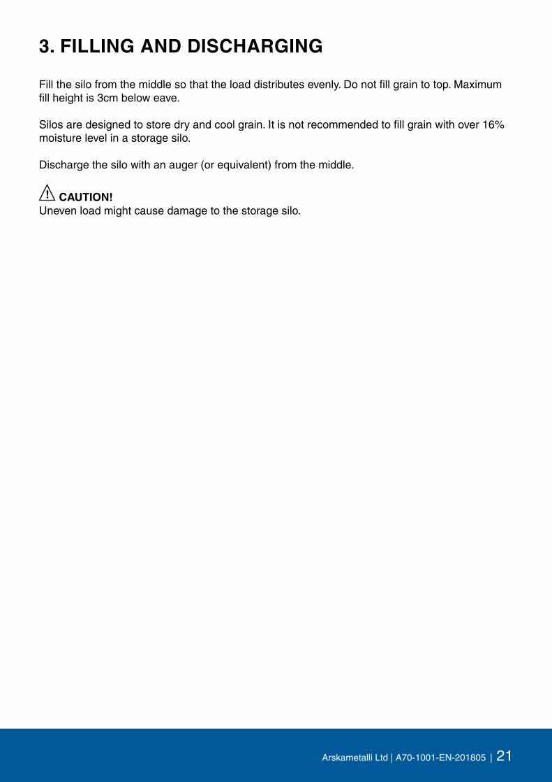
3. FILLING AND DISCHARGING
Fill the silo from the middle so that the load distributes evenly. Do not fill grain to top. Maximum fill height is 3cm below eave.
Silos are designed to store dry and cool grain. It is not recommended to fill grain with over 16% moisture level in a storage silo.
Discharge the silo with an auger (or equivalent) from the middle.
! CAUTION!Uneven load might cause damage to the storage silo.

22 | A70-1001-EN-201805 | Arskametalli Ltd
4. OPTIONS
Auger cover pipe 200cm HJ900_27
Auger cover hood HJ900_29
Auger wall outlet HJ900_24
Auger wall outlet cover HJ5530
Wall element with manhole (incl. hatches) HJ900_08
Pipe joint to top cone Ø200 HJ900_17
Butyl mass AR6525
Sealant extruder AR6526
Grain level monitor AR6528
Ø4,8m
Extra layer 16m3 (weight 200kg) HJ820
Extra reinforcements for two layers 12pcs HJ830
Roof HJ840
Ø5,6m
Extra layer 21m3 (weight 230kg) HJ930
Extra reinforcements for two layers 14pcs HJ940
Roof HJ945
Ø6,4m
Extra layer 27m3 (weight 260kg) HJ960
Extra reinforcements for two layers 16pcs HJ970
Roof HJ975
Ø7,2m
Extra layer 34m3 (weight 290kg) HJ982
Extra reinforcements for two layers 18pcs HJ984
Roof HJ985

Arskametalli Ltd | A70-1001-EN-201805 | 23
NOTES

All rights reserved.
Arskametalli LtdSaarentaantie 33FI-31400 Somero
www.arskametalli.fi