Rotors in Hover and Axial Flight - NASA · Performance Optimization for Rotors in Hover and Axial...
41
- NASA Contractor Report 177524 Performance Optimization for Rotors in Hover and Axial Flight T. R. Quackenbush D. A. Wachspress A. E. Kaufman D. 6. Bliss ( NlaSA-CB- 177 524) EC3 bCfORS III BCVEE BND APXA1 ELlGHir FEB FOfc A4ICE O€TItlIZATZUI lit3 9- 2 C9 7 3 (Ccntinuum Dynaaics) 41 CSCL GIA Unclas 63/02 020114'iU * CONTRACT NAS2-12789 April 1989 National Aeronautics and Space Administration https://ntrs.nasa.gov/search.jsp?R=19890011602 2018-08-25T16:13:34+00:00Z
Transcript of Rotors in Hover and Axial Flight - NASA · Performance Optimization for Rotors in Hover and Axial...
-
NASA Contractor Report 177524
Performance Optimization for Rotors in Hover and Axial Flight T. R. Quackenbush D. A. Wachspress A. E. Kaufman D. 6. Bliss
( NlaSA-CB- 177 524) EC3 bCfORS III B C V E E BND A P X A 1 ELlGHir
FEB FOfc A 4 I C E O € T I t l I Z A T Z U I lit3 9- 2 C9 7 3
(Ccntinuum D y n a a i c s ) 4 1 CSCL GIA Unclas
63/02 020114'iU
* CONTRACT NAS2-12789 April 1989
National Aeronautics and Space Administration
https://ntrs.nasa.gov/search.jsp?R=19890011602 2018-08-25T16:13:34+00:00Z
Performance * in Hover and
!
A
Optimization for Rotors Axial Flight
T. R. Quackenbush D. A. Wachspress A. E. Kaufman
Continuum Dynamics, Inc., Princeton, New Jersey
D. B. Bliss
Duke University, Durham, North Carolina
Prepared for Ames Research Center
April 1989 CONTRACT NAS2-12789
National Aeronautics and Space Administration
Ames Research Center Moffett Field, California 94035
TABLE OF CONTENTS
Section
Nomenclature
1 INTRODUCIlON
2 REVIEW OF BACKGROUND INFORMATION AND PREVIOUS RESEARCH
2.1 The Influence Coefficient Approach to Free Wake Analysis 2.2 Background on Rotorcraft Design Optimization Efforts
3 DEVELOPMENT OF THE OPTIMIZATION ANALYSIS
3.1 Outline of the Optimization Solution Method 3.2 Description of the Linear Optimization Algorithm 3.3 Implementation of the Performance Optimizer
4 RESULTS OF SAMPLE PROBLEMS
4.1 Sample Calculations in Hover 4.2 Sample Case in Axial Flight
5 CONCLUSIONS AND RECOMMENDATIONS FOR FUTURE WORK
6 REFERENCES
V
1
2
2 6
8
8 10 13
16
16 30
32
35
PRECEDING PAGE BLAEjK NOT flLMEO
iii

NOMENCLATURE
.
a( member of coefficient vector for constraint equations
b( scalar on RHS of constraint equations
AP perturbation in rotor power (objective function), nt-m/sec
AP* auxiliary objective function in the optimization routine
P( ) member of coefficient vector in the linearized power equation
vector of perturbations in crossflow velocities at wake collocation points, d s e c
vector of residual crossflow velocities at wake collocation points, d s e c
a ) influence coefficient submamces
AT perturbation in rotor thrust, nt.
T( member of coefficient vector in the linearized thrust equation
”
A w O
vector of perturbations in downwash velocities at blade control points, m/sec
vector of residual downwash velocities at blade control points, ndsec *
” vector of perturbations in wake collocation point positions, m.
slack variables used in setting up equality constraints Y( )
z( component of the auxiliary objective function
-.
vector of perturbations in bound circulation, m2/sec
vector of perturbations in blade design (typically blade twist in radians) 4
V
PRECEDING PAGE BLANK NOT FILMED
I
1. INTRODUCTION
The optimization of performance in hover and axial flight is an issue of continuing importance in the rotorcraft community. A prerequisite for addressing the requirements of rotorcraft designers in this area is a reliable, generally applicable performance prediction program for evaluating designs whose configuration is thoroughly specified. However, rotorcraft designers usually begin the design process with a notional rotor system, and often only the gross features of the rotor geometry (i.e., number of blades, radius, etc.) may be f m l y fixed. Successive mal and error efforts to find a detailed design (by varying chord, twist, taper and other layout parameters) to meet the performance specifications is inevitably a time-consuming undertaking. In the process, still more promising designs may be missed, even with systematic parametric studies. Therefore, a1 though advanced computational tools for predicting 'open loop' hover performance are useful in guiding design efforts and abbreviating cut-and-try work with expensive subscale models, they themselves are used to best advantage when they are guided by formal optimization routines that take advantage of numerical optimization procedures.
The evaluation of candidate optimization procedures turns on a crucial requirement: accurate hover performance prediction must be coupled with practical and efficient optimization schemes if the effort to develop a truly advanced and generally useful design capability is to succeed. The first task, that of developing computational tools to reliably analyze rotor performance for specified configurations, has been under study for over thirty years. Much of the work in this area has centered around efforts to approximate crucial rotor wake effects through generalizations of vortex wake trajectories from empirical data (Refs. 1 and 2) or through interpolations between 'representative' free vortex computations (Ref. 3). Reference 4 describes the inadequacies of many current performance analyses based on momentum theory or on prescribed wake treatments of inflow. It has long been clear that the preferred approach is the explicit computation of full free wake vortex flows; this approach avoids reliance on particular data sets and yields force-free, physically valid wakes which enhance confidence in performance predictions. The next section will summarize previous work in the development of free wake analyses as well the recent development of a new approach to the problem based on an influence coefficient formulation.
The second requirement for a successful optimization analysis is that i t efficiently evaluate candidate designs with minimal resort to repeated calls of the computationally expensive open-loop performance analysis. The discussion below will outline the unique advantages of applying an influence coefficient analysis to the optimization problem. This analysis, dubbed EHPIC (Evaluation of Hover Performance using Influence Coefficients), has proved to be the ideal foundation for a free wake optimization routine, since its formulation permits straightforward evaluation and exploitation of information on the gradients in performance due to design changes. Although free wake analyses inevtiably carry a computational penalty relative to simplified wake models, the results presented below will show how an optimization analysis based on influence coefficients can perform efficient exploration of design space without sacrificing the refined physical model associated with free wake treatments.
1
2. REVIEW OF BACKGROUND INFORMATION AND PREVIOUS RESEARCH
This section lays the groundwork for the discussion of the results of the current effort by summarizing relevant background information. The first subsection recapitulates the development of the EHPIC code and introduces the important concepts that were carried over into the current effort. The second subsection reviews previous work in rotor performance optimization.
2.1 The Influence Coefficient Approach to Free Wake Analysis
Early efforts to develop free wake hover models (Refs. 5 and 6 ) were hampered by long computation time and poor (or nonexistent) convergence. Recently, a new approach to the free wake problem was devised (Refs. 7 and 8) which incorporates curved vortex elements (Refs. 9 and 10) as an aid to computational efficiency in addtion to a new wake relaxation scheme. This new approach solves for the free vortex geometry while circumventing the well-documented convergence problems associated with previous time- marching simulations through the use of an influence coefficient approach. As will be described below, the EHPIC code has produced accurate performance predictions for a wide variety of rotor systems in hover, and has proved to be flexible and robust.
The general objective of a free wake hover analysis is to find the wake geometry that, for a specified rotor geometry, satisfies two conditions: first, that the wake filaments are in free motion; and second, that the flow tangency condition is satisfied on the blade. To achieve the free motion condition, the wake filament trajectories must be tangent to the local velocity vector evaluated on the filament when viewed in a rotating reference frame, Le., there must be no crossflow velocity components at any point on the filaments under force free conditions. The coupled free wakebifting surface hover analysis proceeds by first making an initial guess for the blade loads and the wake geometry. This initial guess will not, in general, satisfy the required conditions, and so must be adjusted in a succession of solution steps. To accomplish this, the independent variables in the problem (the bound circulation at stations along the blade and the vortex wake position coordinates) are systematically perturbed, and the effect of these perturbations on the dependent variables (the downwash on the blade and crossflow velocities in the wake) are summed and formed into influence coefficients. These coefficients allow the construction of a set of simultaneous linear equations in matrix form which predict the change in dependent variables due to the changes in independent variables. The coefficient array so formed can be used to null the crossflow and downwash velocities by inverting it and multiplying it by the vector of residual velocities. The influence coefficient array appears in a linear system of equations in the following form:
The independent variables on the right hand side are, respectively, the position perturbations and bound circulation perturbations from the initial state, while the dependent
2
variables on the left hand side represent the crossflow velocities in the wake and the downwash at the blade. The Q submatrices relate portions of these vector variables to one another.
These variables, of course, represent perturbations about an initial guess, which in general features some nonzero residual velocities on the left hand side. Were the problem purely linear, inverting this matrix and multiplying it by the residual velocity vector would yield a vector of wake displacements and circulation perturbations that would exactly null the velocities in question, Le.,
In general, the process must be repeated due to the inherent nonlinearity of the problem, and only small fractions of the residual velocities are nulled in each iteration. In practice, this approach has been found to have robust convergence properties, despite the complexity of the relaxation procedure. For realistic rotor configurations with up to ten wake filaments per blade, convergence is achieved after ten to fifteen relaxation steps.
In the EHPIC code the wake vortex filaments are represented by curved vortex elements which provide an efficient means to perform the Biot-Savart integrations necessary for the evaluation of wake-induced velocities. A lifting surface analysis is used to evaluate the thrust and induced drag on the rotor. Each blade is modeled by a vortex lattice, and the relaxation solution produces a vector of bound circulation values that null the downwash at each control point. Using the local values of free stream and induced velocity, the Joukowski law is used to find the force and moment on each lattice element. This procedure also produces a spanwise lift coefficient distribution that is used, along with the local Mach number, in a look-up scheme that provides the profile drag coefficient of that section.
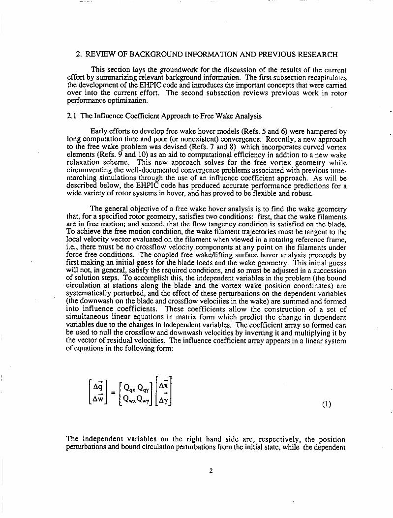
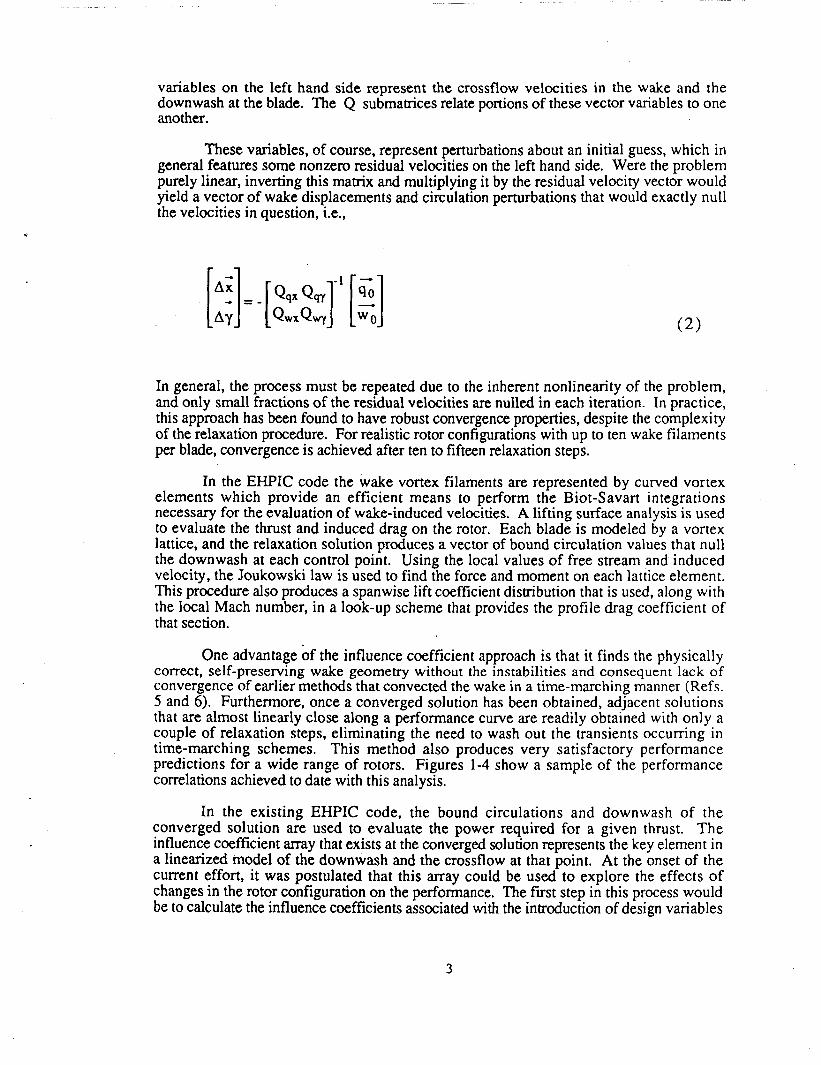
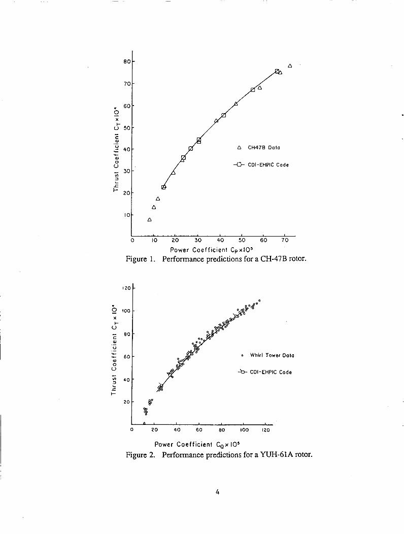
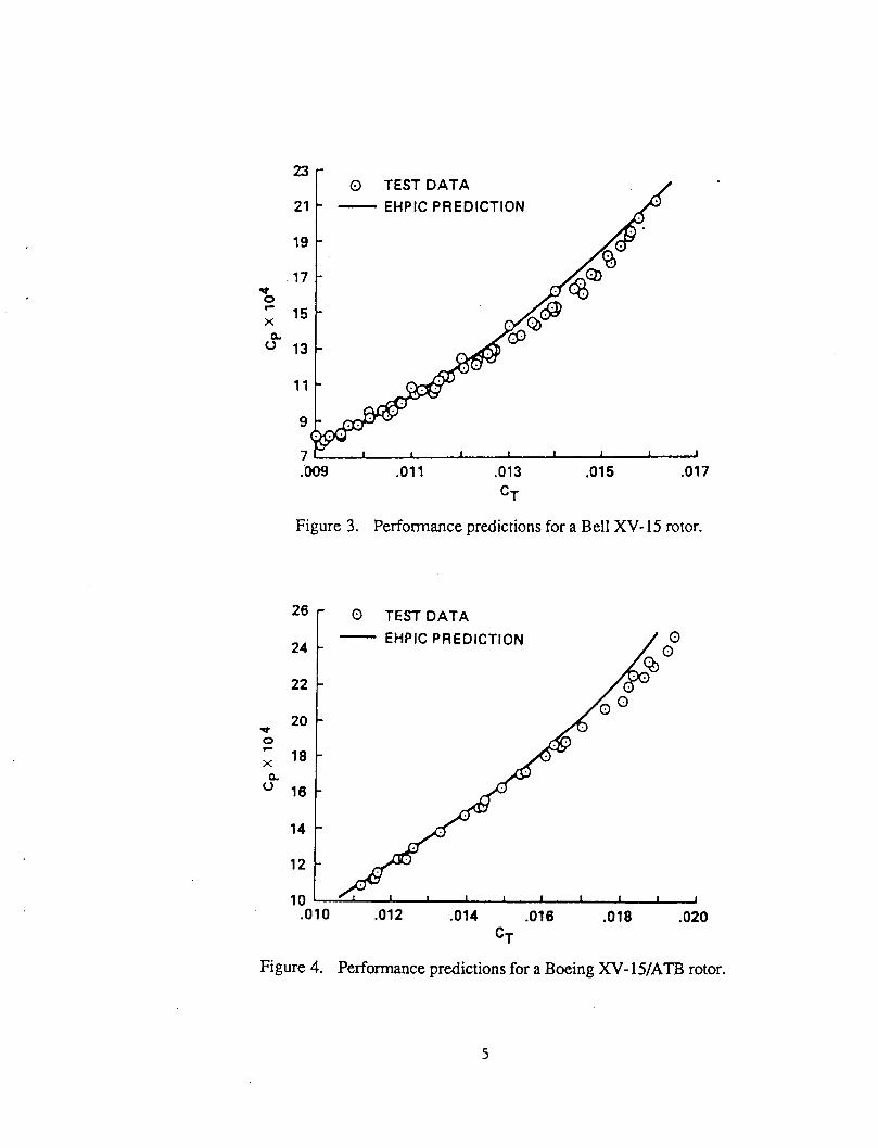
One advantage of the influence coefficient approach is that it finds the physically correct, self-preserving wake geometry without the instabilities and consequent lack of convergence of earlier methods that convected the wake in a time-marching manner (Refs. 5 and 6) . Furthermore, once a converged solution has been obtained, adjacent solutions that are almost linearly close along a performance curve are readily obtained with only a couple of relaxation steps, eliminating the need to wash out the transients occurring in time-marching schemes. This method also produces very satisfactory performance predictions for a wide range of rotors. Figures 1-4 show a sample of the performance correlations achieved to date with this analysis.
In the existing EHPIC code, the bound circulations and downwash of the converged solution are used to evaluate the power required for a given thrust. The influence coefficient array that exists at the converged solution represents the key element in a linearized model of the downwash and the crossflow at that point. At the onset of the current effort, it was postulated that this array could be used to explore the effects of changes in the rotor configuration on the performance. The fiist step in this process would be to calculate the influence coefficients associated with the introduction of design variables
3
D CH478 Dolo
a CDI-EHPIC Code
, , , I O
0 IO 20 30 40 50 60 70
Power coef f ic ient C p x l O s
Figure 1. Performance predictions for a CH-47B rotor.
100 X I-
V - 0 0 ’ C aJ V .- .- + - 60. aJ 0 V c
2 4 0 -
L Jz I-
‘ O t :
o Whirl Tower Data
h- CDI-EHPIC Code
~~ ~
0 20 4 0 60 eo 100 I 20
Power Coeff ic ient C,x 10’ Figure 2. Performance predictions for a YUH-61A rotor.
4
.011 .013 .015 .017
CT
Figure 3. Performance predictions for a Bell XV- 15 rotor.
26 r o TESTDATA
24
22
20
18
16
d
2 X Q
14
12
10 .010 .012 .014 ,016 .018 ,020
CT
Figure 4. Performance predictions for a Boeing XV- 15/ATB rotor.
5

that represent new degrees of freedom. The expectation was that the linearized treatment of the coupled blade/wake model could serve as the foundation of a design optimization analysis. Before embarking on a description of the development of this analysis, though, it is appropriate to review previous efforts on rotor performance optimization.
2.2 Background on Rotorcraft Design Optimization Efforts
There exists a substantial body of literature on numerical optimization procedures that are suitable for guiding such design perturbations for the purpose of achieving specific performance goals. Recent reviews of aerospace- and rotorcraft-oriented applications of numerical optimization (Refs. 11-13) give evidence of the maturity of these techniques; examples of particular applications of optimization to rotorcraft issues such as flight path management, vibration suppression, and weight minimization extend back nearly twenty years (Refs. 14-17). Nearly all of these studies rely on qualitatively simiIar approaches; an objective function (e.g., vibratory load levels or figure of merit) is defined along with a set of design parameters to be varied. Limitations are placed on the variations allowed in these quantities in the form of inequality constraints. Initial estimates of parameter values to meet the specified performance levels are made. Using approximations to the actual nonlinear relations governing the objective function, the design parameters are varied in the vicinity of the initial estimate to reach the desired level of this function.
Following the early work of Stepniewski and Kalmbach (Ref. 14) in the application of optimization techniques to rotorcraft, a variety of efforts were undertaken to attack the problem of rotor performance optimization using numerical techniques, many of them concentrated in the last six or seven years. Moffitt and Bissell (Ref. 18) undertook a general examination of rotor airloads in both hover and forward flight, using a prescribed wake aerodynamic model with circulation coupling, with the aim of finding airload distributions that led to a minimum power required for a specified thrust; they derived an optimized twist distribution for the Black Hawk rotor in hover that was broadly similar to actual design, although the performance improvement offered by the final design appeared to be small (roughly a 1% reduction in power required). Nagashima and Nakanishi (Ref. 19) studied hover performance optimization for coaxial rotors, employing both a closed- form "generalized momentum" model of the wake as well as a simplified free wake model based on vortex rings. They reached preliminary conclusions about optimum levels of thrust sharing using their momentum treatment, but their work with free wake/vortex ring models was hampered by the familiar instabilities inherent in time-domain free wake calculations in hover. Chung (Ref. 20) also used a simplified free wake model to attack the formal optimization problem for hover performance. Finally, Walsh, Bingham, and Riley (Ref. 21) describe the assembly of several "off-the-shelf' aerodynamic and vehicle trim models (e.g., C-81) and a commonly availabIe optimization routine (CONMIN) into a broadly applicable blade design optimizer for hover and forward flight. Some of the component analyses within the overall routine were highly simplified models, notably the strip theory performance program used for hover.
This previous work represents a broad range of accomplishment in the general area of performance optimization, although as a general rule these efforts have chosen to use simplified aerodynamic models such as strip theory or wake prescription. This doubtless has been a response to the need to provide designers with computationally efficient tools; however, now that more and more computational power is becoming routinely available to workers at all levels in the rotorcraft field, the time has come to consider more advanced methods. There is also a very basic technical issue in play here: simplified models, while of course efficient, lack the generality and accuracy of more advanced treatments (such as free wake models), and so their use in an optimization analysis undermines confidence in
6
the true optimality of the final solution. A fundamental assumption of the current effort is that an advanced free wake analysis like that embodied in the EHPIC code is required for a reliable optimization treatment.
Details of the procedures that drive the optimization routine developed for this effort will be discussed in the next section. The important point to note for current purposes is that, as suggested above, the arrays of linearized influence coefficients in the EHPIC analysis can be used to generate the local approximations to the rotor performance that are, in turn, incorporated into the optimization procedures. Thus, the influence coefficient approach to hover performance is uniquely well suited to serve as a basis for an analysis to optimize hover performance. The opportunity presented by the coupling of these two technologies - influence coefficient relaxation and numerical optimization - is further highlighted if account is taken of the highly accurate performance results obtained by the EHPIC free wake analysis. The description of the steps taken to exploit this opportunity is the subject of the discussion in the balance of this report.
7
3. DEVELOPMENT OF THE OPTIMIZATION ANALYSIS
3.1 Outline of the Optimization Solution Method
In principle, the existing hover performance code could be directly applied to the design optimization problem by simply running performance evaluations for a suitably broad matrix of candidate design configurations. In practice, this would involve a prohibitive expenditure of time and computational resources; pure trial and error experimentation is, of course, too inefficient a process for any but the simplest design problems. The question of computational efficiency is even more important in this context than it is with more research-oriented applications; by its very nature, design optimization must be a usable engineering tool Fortunately, by coupling a modern numerical optimization routine to the relaxation solution method used in the EHPIC code, the process of computational cut-and-try can be greatly abbreviated without sacrificing the inherent high accuracy associated with a free wakebifting surface loads analysis.
As was discussed in Section 2, a unique and pertinent feature of the EKPIC hover analysis approach is that it generates arrays of influence coefficients that relate loads on the blade to downwash velocities both on the rotor blades and in the wake. Using these arrays, solutions can be obtained for configurations whose design has been completely specified. The nature of the relaxation solution method is such that the final converged solution can be perturbed to find the performance of rotors with slightly different values of twist or pitch. In such perturbation calculations, the changes in built-in twist or pitch simply serve to determine the new boundary conditions that the coupled blade/wake analysis must satisfy. It is important to realize, however, that there is no fundamental obstacle to expanding the mays of influence coefficients to allow introducing such design perturbations as new independent variables in the problem. Thus, the influence coefficient approach provides a natural foundation for a systematic study of the performance effects of design perturbations around an initial configuration.
Other free wake hover analyses based on Lagrangian time-stepping do not share this advantage. Any time-marching calculation of rotor loads develops a transient response once the system is disturbed, and several rotor revolution periods are required to "wash out" such disturbances (design changes, for example) before a steady solution is obtained. The computational cost of such continual readjustments would be prohibitive in the context of an optimization problem.
To set up the optimization problem using a relaxation approach it is first necessary to introduce design variables into the solution method, along with a performance measure and appropriate constraint equations to ensure that the design problem is well posed. Unlike the 'open-loop' hover problem, where the number of governing equations equaled the number of independent variables in the analysis, here there is an excess of degrees of freedom; this necessitates the introduction of a solution algorithm that selects from among the essentially infinite number of possible design configurations based upon the desire to maximize or minimize the chosen performance measure while satisfying the stated constraints.
The candidate algorithms for this application fall into two broad categories: linear and nonlinear optimization routines. The attraction of applying a nonlinear optimization routine is, of course, that very general functional relationships are permitted between the design variables and the objective and constraint functions. Since the governing equations for the hover performance problem are in fact highly nonlinear, the appeal of applying one of several existing nonlinear programming algorithms to this problem was quite strong.
a

However, linear optimization routines have an advantage in that they rest upon a more mathematically rigorous foundation and hence are more reliable than their nonlinear counterparts; if a fundamentally nonlinear problem can be treated adequately by a succession of local linearizations in design space, then the application of a linear optimization analysis becomes quite attractive. The success of the influence coefficient approach to free wake problem in hover was an example of the potential of just such an approach. Thus, it was resolved to rely on a linear optimization routine for this effort, with successive local linear models of the couple blade/wake system obtained using methods similar to the influence coefficient evaluation techniques embodied in the EHPIC code.
The details of the particular linear optimization routine selected for this effort are given in Section 3.2 below. However, the general requirements to set up the problem are that both the objective function and the constraint equations be expressed as linear functions of the design variables. The objective function selected for this effort was the total power consumed by the rotor in hover, and the design problem addressed was the minimization of power required at a specified thrust. Although in general any design variable can be introduced (e.g. chord, sweep, anhedral, etc.), for this preliminary investigation the twist distribution on the rotor blade was selected. The expanded set of equations governing the optimization problem then are
AT = [Tx] {A;) +[Ti {A;)+ [Te] { A i ) (4)
where 8 represents the blade twist distribution. The general optimization problem consists of a systematic search of the space of design variables to find the combination that leads to the minimum power for a given thrust; this corresponds to making the largest possible negative change in the objective function, AP , while constraining AT to be zero.
In order to ensure that changes in blade design still lead to a coupled blade/wake system that satisfies the required flow tangency conditions, additional constraints must be applied in the form of an expanded version of Equation 1, i.e.,
[Ai].[ Q,, QsY Qqe] Aw Q w x Q v Q w e
[;I A0
If the perturbations on the left hand side are set to zero, these equations can be treated as constraints on the changes in the wake position, the bound circulation, and the design variables. These constraints, taken together with Equations 3 and 4, form most of the necessary input to a linear optimization routine.
9
As may be inferred from the form of problem posed here, the solution method developed for the EHPIC code provides the ideal foundation for the formulation of an efficient optimization procedure. Most of the coefficients in the constraint relationships summarized by Equation 5 are computed by the 'open loop' EHPIC code, as indicated by Equation 1, and the additional coefficients have been incorporated by extending the existing software. The calculation of the coefficients in Equations 3 and 4 is considerably more involved but has been greatly simplified by the existence the linear velocity derivatives in Equation 5. For example, the computation of the sensitivity of thrust and induced power to changes in the bound circulation was aided by the existence of derivatives of the downwash at the blade with respect to this quantity. The formulation of derivatives of the profile power is somewhat more complicated and required more new coding, but did not present a fundamental obstacle.
With the basic form of the problem established, the actual algorithm used for this effort can be described. This discussion will be followed by additional details on the coupling of this new capability to the existing EHPIC code, a coupling that, as will be discussed later, has the potential for adding a variety of significant new capabilities to the current formulation.
3.2 Description of the Linear Optimization Algorithm
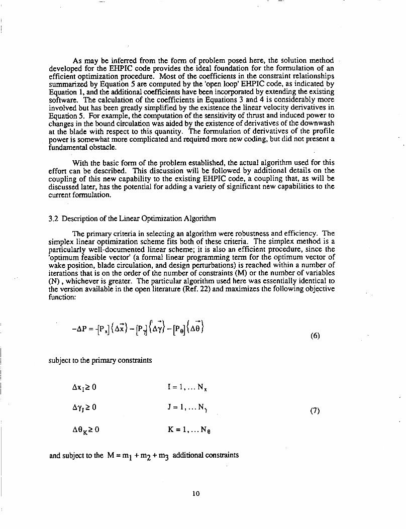
The primary criteria in selecting an algorithm were robustness and efficiency. The simplex linear optimization scheme fits both of these criteria. The simplex method is a particularly well-documented linear scheme; it is also an efficient procedure, since the 'optimum feasible vector' (a formal linear programming term for the optimum vector of wake position, blade circulation, and design perturbations) is reached within a number of iterations that is on the order of the number of constraints (M) or the number of variables (N) , whichever is greater. The particular algorithm used here was essentially identical to the version available in the open literature (Ref. 22) and maximizes the following objective function:
-AP = {Px] (A;) - [Pd {A;) -[Po] { A i )
subject to the primary constraints
Ax12 0 I = 1, ... N,
N l Ay,2 0 J = 1, ...
A8,2 0 K = 1, ... Ne
and subject to the M = ml + m2 + m3 additional constraints
10

[aix](A;) +[aiy](A;) +[a,l{AB) 5 bi ( b i 2 0) i = 1,2, ... ml
[a, ( A;) + [aj,] {A;} + [aj, ] { A;) 1 b (b, 2 0) j = 1 ,2,. . . m2 (9)
Several important issues need to be clarifkd to fit the hover optimization problem into this general form. It should be noted that maximizing -AP , the negative change in power, is equivalent to minimizing AP algebraically. Additionally the primary constraints (Eq. 7), as written, prohibit any negative perturbations in the independent variables. This creates an unwanted artificial restriction on the variables which is eliminated by transforming each variable as follows:
A 8 ’ , 1 0 , A 8 ” , 1 0 , K = 1, ... No
The optimization problem is then solved for the primed variables. These transformations are used in the objective function as well as the constraint equations. The m l and m2 inequality constraints are applied to all of the independent variables to resmct the changes in each call of the optimization routine to a region where the linear approximations are valid. The inequality constraints can also place user-defined limits on the total magnitude of the design variables. (This capability can be invoked, for example, as a simple way to factor forward flight design considerations into the hover problem. Large amounts of washout on rotor blades are undesirable in forward flight, and bounds on the total twist across the blade could be used as a first-order method to keep blades optimized for hover within the forward flight design constraints.)
The equality constraints in the form of Equation 10 consist of the thrust constraint and the constraints on the changes in the wake position, the bound circulation and the design variables required to satisfy the free wake boundary conditions discussed in the previous section. The coefficients of these equations can be positive, negative or zero, but by convention the constants on the right hand side are always nonnegative.
11
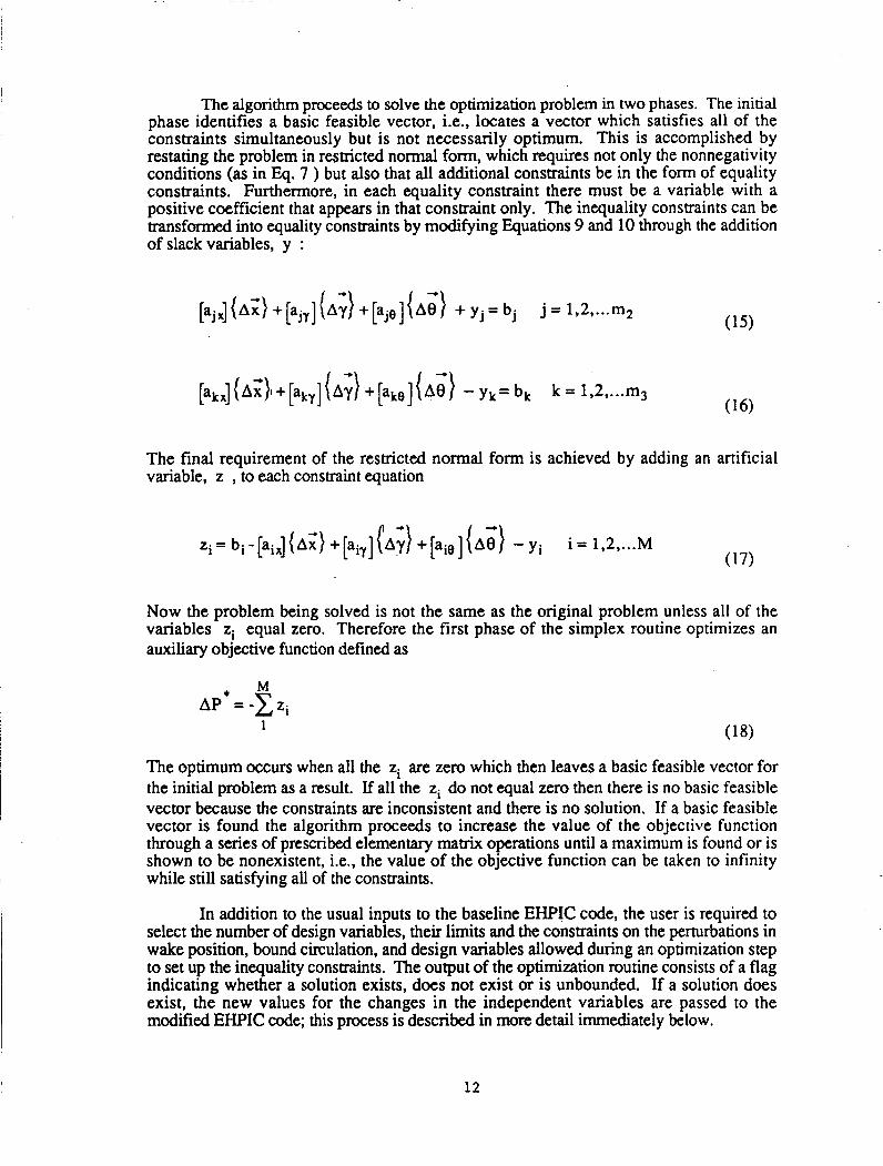
The algorithm proceeds to solve the optimization problem in two phases. The initial phase identifies a basic feasible vector, i.e., locates a vector which satisfies all of the constraints simultaneously but is not necessarily optimum. This is accomplished by restating the problem in restricted normal form, which requires not only the nonnegativity conditions (as in Eq. 7 ) but also that all additional constraints be in the form of equality constraints. Furthermore, in each equality constraint there must be a variable with a positive coefficient that appears in that constraint only. The inequality consmints can be transformed into equality constraints by modifying Equations 9 and 10 through the addition of slack variables, y :
[ . jx] (A;)+pj l ] (~;}+[aje] (A~} +y ,=b , j = 1,2, ... m2
The final requirement of the restricted normal form is achieved by adding an artificial variable, z , to each constraint equation
Now the problem being solved is not the same as the original problem unless all of the variables zi equal zero. Therefore the first phase of the simplex routine optimizes an auxiliary objective function defined as
M AP' = -c zi
The optimum occurs when all the zi are zero which then leaves a basic feasible vector for the initial problem as a result. If all the zi do not equal zero then there is no basic feasible vector because the constraints are inconsistent and there is no solution. If a basic feasible vector is found the algorithm proceeds to increase the value of the objective function through a series of prescribed elementary matrix operations until a maximum is found or is shown to be nonexistent, i.e., the value of the objective function can be taken to infinity while still satisfying all of the constraints.
In addition to the usual inputs to the baseline EHPIC code, the user is required to select the number of design variables, their limits and the constraints on the perturbations in wake position, bound circulation, and design variables allowed during an optimization step to set up the inequality constraints. The output of the optimization routine consists of a flag indicating whether a solution exists, does not exist or is unbounded. If a solution does exist, the new values for the changes in the independent variables are passed to the modified EHPIC code; this process is described in more detail immediately below.
12
3.3 Implementation of the Performance Optimizer
The coupling of the optimization algorithm described above to the EHPIC code was simplified by some of the inherent characteristics of the influence coefficient approach to the free wake problem in hover. As was described in Reference 8, the EHPIC code has the ability to restart its solution process from a converged result with a small change in the collective pitch; this drives the coupled bladdwake system away from the proper free wake solution, and the analysis must re-invoke the quasi-linear EHPIC relaxation several times to reattain equilibrium; usually four or five steps are required. This capability has been used extensively in early applications of EHPIC to generate new solutions for several adjacent collective settings without a complete re-initialization of the solution.
Several steps are required to relax to adjacent solutions at nearby collectives, since the converged result that serves as the point of departure starts with "old" information on the wake geometry and the circulation distribution. This is also true of calculations that are restarted using different built-in twist, the type of calculations required for a design optimization study. It would be possible to do the optimization problem by systematically applying such twist changes to baseline designs and computing the resulting performance using the restart capability of the unmodified EHPIC code. However, not only would the restart require several steps to eliminate residual velocities, but adjustments in the collective would have to be made to preserve constant thrust on the rotor. In the context of the unmodified EHPIC code, then, the repetitive performance evaluations for different designs could become awkward and inefficient.
By taking advantage of the capabilities of the linear optimization algorithm, though, these computations can be undertaken much more efficiently. For example, the optimization routine described above produces predictions not only of the design changes needed to reduce power but also of the wake geometry and bound circulation perturbations that are compatible with these changes, given the constraints of constant thrust and the free wake boundary conditions. The initial computation of all of these perturbations is carried out immediately following the completion of the initial convergence of the baseline solution. The design perturbations must, of course, be added to the baseline design, but to accelerate the re-convergence of the solution the perturbations in wake position and bound circulation are added on, as well. This has the effect of moving the complete coupled system very close to its proper free wake equilibrium so the elimination of any residual crossflow or downwash velocities can be achieved with only one or two further calls of the EHPIC relaxation procedure. Given the thrust constraint, the need for separate adjustments to preserve the desired thrust level are unnecessary. Finally, since the magnitude of each of the perturbations is subject to reasonably tight inequality constraints, the potential for significant excursions in the wake solution is reduced. This is a potentially very useful aspect of the linear optimization approach which could be extended to improve the basic relaxation method used in the EHPIC code, as will be described later.
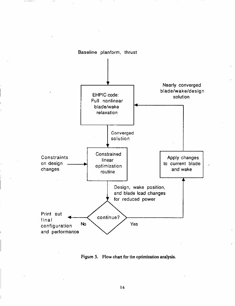
The sequence of events in the final form of the Phase I analysis is depicted in the flow chart in Figure 5. The coupling of the linear optimizer to the EHPIC code is the most obvious single new feature in the analysis, although EHPIC itself has been extensively modified to compute and store the coefficients of the constraint equations as well as those governing the linearized equation describing the objective function, i.e., the power. At present, there are no pre-set performance targets for the optimization analysis (e.g., 5% power decrease at constant thrust); for the purposes of the Phase I technology demonstration, it has been permitted to run through as many loops as required to produce significant performance improvements (usually at least ten ). In the current code, each successive change in the blade design produces a new baseline from which the optimization routine proceeds until instructed to halt.
13
EHPIC code: Full nonlinear
relaxation L blade/w a ke/des ig n
solution
Converged solution
I b lade/w a ke P------
Constrained linear
optimization i routine
Constraints on design changes
Apply changes to current blade
and wake
A Design, wake position, and blade load changes for reduced power
Print out f i na l configuration No Yes
and performance
Figure 5. Flow chart for the optimization analysis.
14
The flow chart also depicts the necessity of specifying the constraints on the independent variables alluded to above. No hard-and-fast rules have yet been developed for setting the magnitude of allowable perturbations, although previous experience with the EHPIC code was helpful in guiding the choices for this preliminary investigation. During restarted runs with EHPIC, it has been found that total increments in twist of roughly one degree can be imposed while still obtaining sure and relatively rapid reconvergence. Given that a typic-' blade layout features a twist distribution discretized into between five and ten spanwise s ,merits, the maximum twist change considered permissible for any single segment in a given optimization step was thus roughly 0.2 degrees, although 0.1 degrees was often chosen to be sure of keeping the coupled blade/wake system in a reasonably linear range of behavior. Numerical experimentation further indicated that simultaneous constraints of roughly 0.01R on Ax and two-to-three percent of the mean bound circulation on Ay were appropriate choices. In a linear optimization analysis, some of the variables will always "hit the stops", i.e, change up to the maximum magnitude allotted them. It is desirable to have the design variables be the pacing quantities in this respect, since incurring large changes in bound circulation or wake position could lead to questionable prospects for successfully reattaining free wake equilibrium with the EHPIC code.
Experience to date indicates no meaningful problems converging to an improved design at a particular step in the calculation as long as the with problem is well posed and properly constrained. Although results can vary considerably depending on the exact blade and wake configurations used, usually three optimization cycles can be executed using the same amount of CPU time required to relax the initial baseline case. Thus, a preliminary rule of thumb appears to be that a design with meaningful improvements in performance can be obtained with two to three times the CPU time of the initial calculation. Considerable reductions in CPU time could be effected in a follow-on effort by simplifying the current (very conservative) programming approach to deriving the design variable coefficients as well as by relaxing the tight inequality constraints on design variables.
15
4. RESULTS OF SAMPLE PROBLEMS
As noted above, for the purposes of the Phase I technology demonstration the design variable chosen for the sample problems was the built-in twist of the rotor blade. The formulation of the problem to this point has been sufficiently general that other variables (e.g., chord, sweep, etc.) could have been chosen; as discussed in Section 5 below, one of the requirements for a more complete follow-on analysis would be to accommodate any such variable. The selection of the twist allowed the best advantage to be taken of existing coding, while still adequately demonstrating the capability developed here.
In the optimization code, the blade layout is specified in much the same way as in the baseline EHPIC code; the user selects the twist, chord, sweep, and anhedral values at the edges of as many as ten separate segments on the span of the blade. Each quantity is assumed to vary linearly between the specified boundary values specified at the segment edges, so the analysis can generate a ten-segment piecewise-linear fit to any nonlinear design distribution. In the examples that follow, the collective pitch (Le., the geomemc pitch at the blade root) was held fixed, while the segments outboard were allowed to distort. For most of the sample calculations discussed below, a representative "generic" rotor blade layout was used. This design featured untapered blades of radius 15 ft. (4.6 m), chord 1.0 ft. (.3Om), a tip speed of 700 f p s (213 m/s), and an NACA 0012 airfoil. In all nearly all cases an initial linear twist distribution of -7.0 degrees across the blade span was assumed, and twenty vortex quadrilaterals were used spanwise and one chordwise.
4.1 Sample Calculations in Hover
The issue of selecting the twist that minimizes power in hover for a given thrust has, of course, long been an issue of interest in the rotorcraft field. It was resolved to demonstrate the capabilities of the optimization routine to address this issue by attacking several representative problems. It is important to point out at the outset, however, that the results here are intended to demonstrate the practicablity of achieving improved designs, even if these are not the theoretical optimum for the overall planform constraints. The optimization of blade twist proved to be a rather "forgiving" problem in that large increments of performance could be achieved with relatively modest changes in the baseline twist, as will be evident in the results below. In light of the importance of increases in hover figure of merit of several pints (such as were routinely realized) and in view of the absence of forward flight constraints that would inevitably affect any design optimized purely for hover, the examination of performance improvements that could be realized with reasonably small changes in the baseline was judged to be the most appropriate objective.
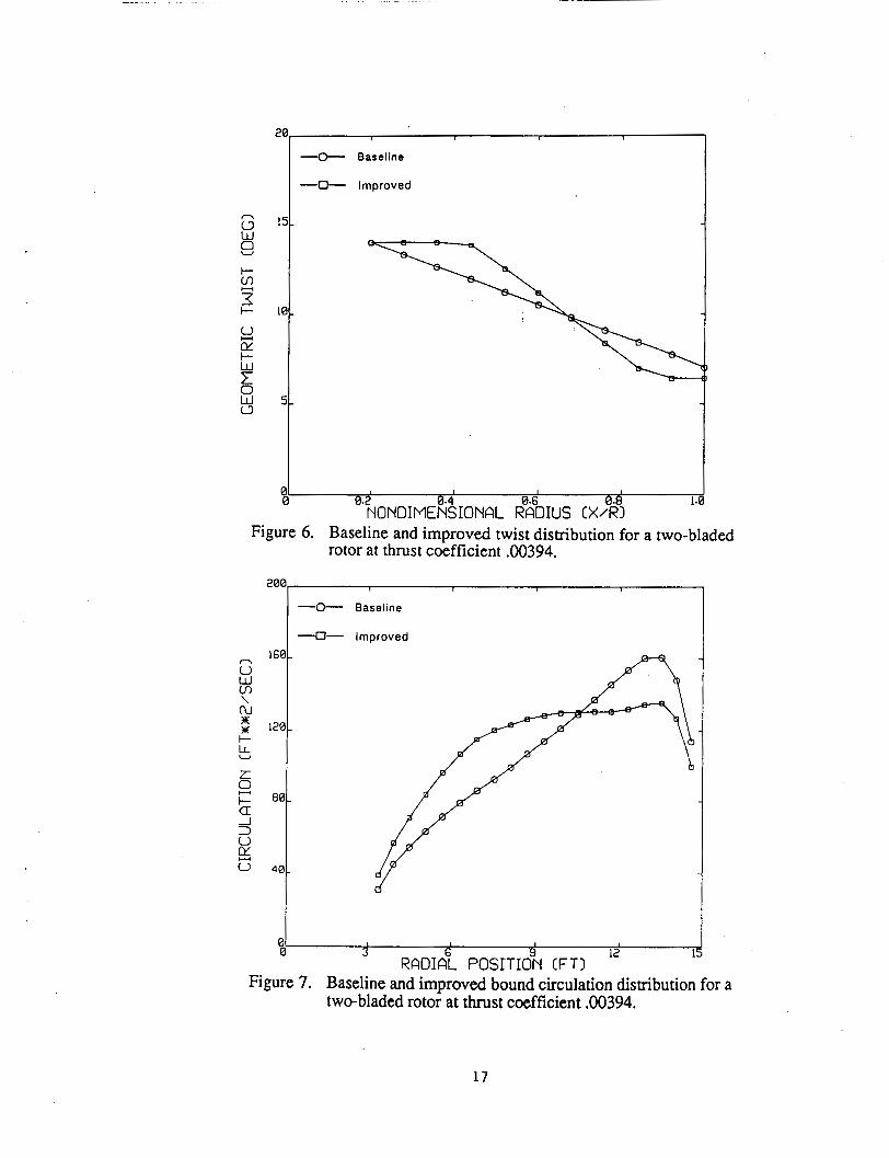
Initially, very simple problems with limited free wakes were examined to test the basic algorithm before more realistic problems were attempted. The first test involved a case with two free filaments, one trailing from the blade tip and one from the root; each featured a single turn of free wake, with prescribed wake used past that point. The baseline rotor was set at a collective pitch corresponding to a moderate thrust coefficient of 0.00394 and the optimization routine was run for ten loops. Figure 6 shows the initial and final twist distribution on the rotor, while Figure 7 compares the bound circulation distributions. The improved configuration keeps the thrust coefficient constant, while reducing the power required by nine percent, corresponding to an increase in the figure of merit from 0.7 10 to 0.763. Clearly, the principal effect of the optimization algorithm is to shift the blade load inboard by increasing the geometric angle of attack near the root and dropping it outboard. This new load distribution is apparent in Figure 7, and is also reflected in a reduction in the induced power, since carrying the load inboard reduced the torque required to drive the rotor (the downwash distribution changes, as well, but not enough to counteract the effect of the shift in loading). The profile power drops only slightly (approximately one percent)
16
20 1
-0- Baseline
-0- Improved
20
16
121
8(
4(
4
Figure 6. Baseline and improved twist distribution for a two-bladed rotor at thrust coefficient .00394.
-0- Baseline
-0- Improved
I
d
3 I I I
RADIZL POSITdN (FTI 12 1
Figure 7. Baseline and improved bound circulation distribution for a two-bladed rotor at thrust coefficient .00394.
17
as a result of the design changes, and it clear both here and in subsequent cases that it is the change in induced power that dominates the optimization process.
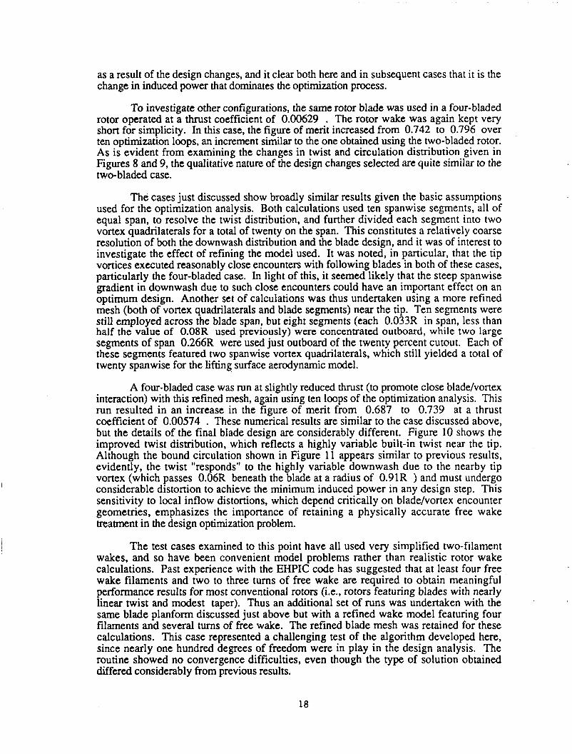
To investigate other configurations, the same rotor blade was used in a four-bladed rotor operated at a thrust coefficient of 0.00629 . The rotor wake was again kept very short for simplicity. In this case, the figure of merit increased from 0.742 to 0.796 over ten optimization loops, an increment similar to the one obtained using the two-bladed rotor. As is evident from examining the changes in twist and circulation distribution given in Figures 8 and 9, the qualitative nature of the design changes selected are quite similar to the two-bladed case.
The cases just discussed show broadly similar results given the basic assumptions used for the optimization analysis. Both calculations used ten spanwise segments, all of equal span, to resolve the twist distribution, and further divided each segment into two vortex quadrilaterals for a total of twenty on the span. This constitutes a relatively coarse resolution of both the downwash distribution and the blade design, and it was of interest to investigate the effect of refining the model used. It was noted, in particular, that the tip vortices executed reasonably close encounters with following blades in both of these cases, particularly the four-bladed case. In light of this, it seemed likely that the steep spanwise gradient in downwash due to such close encounters could have an important effect on an optimum design. Another set of calculations was thus undertaken using a more refined mesh (both of vortex quadrilaterals and blade segments) near the tip. Ten segments were still employed across the blade span, but eight segments (each 0.033R in span, less than half the value of 0.08R used previously) were concentrated outboard, while two large segments of span 0.266R were used just outboard of the twenty percent cutout. Each of these segments featured two spanwise vortex quadrilaterals, which still yielded a total of twenty spanwise for the lifting surface aerodynamic model.
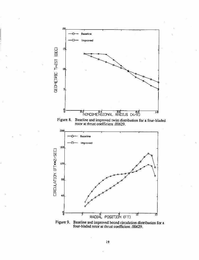
A four-bladed case was run at slightly reduced thrust (to promote close blade/vortex interaction) with this refined mesh, again using ten loops of the optimization analysis. This run resulted in an increase in the figure of merit from 0.687 to 0.739 at a thrust coefficient of 0.00574 . These numerical results are similar to the case discussed above, but the details of the final blade design are considerably different. Figure 10 shows the improved twist distribution, which reflects a highly variable built-in twist near the tip. Although the bound circulation shown in Figure 11 appears similar to previous results, evidently, the twist "responds" to the highly variable downwash due to the nearby tip vortex (which passes 0.06R beneath the blade at a radius of 0.91R ) and must undergo considerable distortion to achieve the minimum induced power in any design step. This sensitivity to local inflow distortions, which depend critically on blade/vortex encounter geometries, emphasizes the importance of retaining a physically accurate free wake treatment in the design Optimization problem.
The test cases examined to this point have all used very simplified two-filament wakes, and so have been convenient model problems rather than realistic rotor wake calculations. Past experience with the EHPIC code has suggested that at least four free wake filaments and two to three turns of free wake are required to obtain meaningful performance results for most conventional rotors (i.e., rotors featuring blades with nearly linear twist and modest taper). Thus an additional set of runs was undertaken with the same blade planform discussed just above but with a refined wake model featuring four filaments and several turns of free wake. The refined blade mesh was retained for these calculations. This case represented a challenging test of the algorithm developed here, since nearly one hundred degrees of freedom were in play in the design analysis. The routine showed no convergence difficulties, even though the type of solution obtained differed considerably from previous results.
18
8
-0- Baseline
1 I 1
-0- Baseline
-0- Improved
120.
80.
40
Figure 8. Baseline and improved twist distribution for a four-bladed rotor at thrust coefficient .00629.
-
-C+- Improved
n 160 I
d I 01 1 1 I I
0 3 6 9 12 I RADIAL POSITION (FTI
Figure 9. Baseline and improved bound circulation distribution for a four-bladed rotor at thrust coefficient .00629.
19

I I 1 I
-0- Baseline
-0- Improved
1. '.~NONDIME%IONAL RBK~DIUS tx%~ Figure 10. Baseline and improved twist distribution for a four-bladed
rotor at thrust coefficient .00574: refined tip mesh. I 1 1 1
-0- Baseline
-0- Improved
I I I
3 1
12 RADIAGL POSITI~N [FTI k
Figure 11. Baseline and improved bound circulation distribution for a four-bladed rotor at thrust coefficient .00574: refined tip mesh.
20
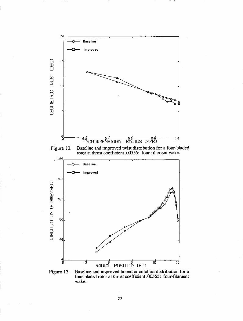
In previous cases, it was noted that ten or so loops of the optimization routine yielded improvements in performance of roughly five points in figure of merit; such an improvement would represent a spectacular enhancement of the rotor's efficiency. Indeed the improvement was so dramatic as to excite suspicion as to whether the simplification of the rotor wake model had something to with these large gains. The runs with more realistic four-filament wake suggested that this was a valid suspicion; after ten loops using the same design variable constraints as the two-filament runs above, the four-filament result displayed a one-point gain in figure of merit ( 0.666 to 0.677 ) at a thrust coefficient of 0.00555 , a considerably less dramatic change than noted earlier. The twist and circulation distributions obtained for this case are shown in Figures 12 and 13, and these reflect considerable differences from the corresponding results in Figures 10 and 11. The tendency to shift load inboard is less pronounced in the four-filament case, and this strategy improves performance less rapidly for the given constraints than in the more simplified two-filament case. The tendency of the blade design to "respond" to the presence of the tip vortex is still very noticeable.
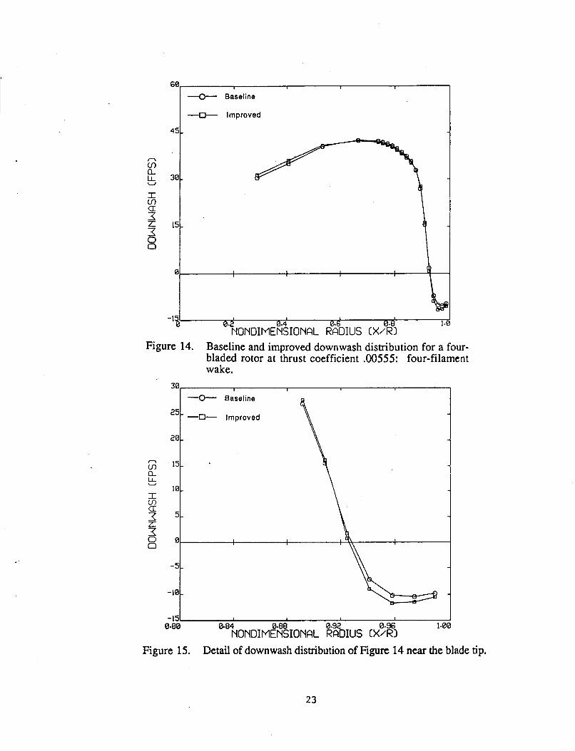
It is also of interest to investigate the changes in the downwash distribution over the blade that come about as a result of the optimization process. Figure 14 indicates a comparison of the spanwise downwash both before and after optimization, indicating the relatively modest apparent changes that take place. Figure 15 shows more detail of the tip region and reflects the increase in upwash near the tip that comes about as a consequence of the tip vortex moving closer to the blade as the design evolves; this new upwash is not reflected in an increase in aerodynamic load because of the reduction in built-in twist that occurs in the vicinity of the tip (note that upwash is negative in Figures 14 and 15).
The basic message of the two test cases just described (the first being the two- filament, refined blade mesh case and the second the four-filament run) is that the nature of the model assumed for the baseline performance calculation can significantly affect the type of solution that is obtained from the optimization routine. This is not in fact a particularly surprising conclusion, since the choice of such input parameters was found to significantly affect rotor performance in the orginal work on the EHPIC code (Refs. 8 and 24). It is important to realize, however, that the introduction of the design variables as degrees of freedom has introduced a new set of dependencies in the fundamental numerical model. For present purposes it is sufficient to note this sensitivity, although the issue of how the choice of design variables affects the final improved blade design must eventually be addressed. It would be desirable to explore this new situation through a set of numerical experiments in which test runs using an initially crude set of design variables (say, a single segment with linear twist spanning the blade) are systematically refined and any evolution of the design solutions noted. However, such a detailed analysis was judged to be inappropriate in a concept demonstration effort such as this and better suited to a follow-on effort aimed at the development and testing of a comprehensive optimization model.
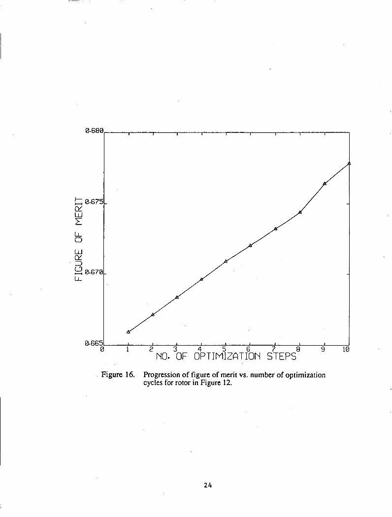
Another important facet of these results is the progression of figure of merit for each optimization step; Figure 16 shows a plot of this progression for the four-filament case and thus gives an impression of potential for performance improvement . As was noted above, the objective of this effort was to assess the potential of this analysis for finding improved rotor designs, even in the absence of a clear optimum configuration. Figure 16 shows clearly that the existing routine can produce such improved designs, though addtional constraints from other flight conditions will inevitably bound the increments in performance that can be achieved. The discussion in Section 5 outlines how the requirements imposed by other performance specifications could be included in the optimization as part of a follow-on effort.
2 1
-0- Baseline
4 Improved
-0- Baseline
4 Improved
i
4 I I
3 6 9 12 15 1 01
0 RADIAL POSITION CFTI
Figure 13. Baseline and improved bound circulation distribution for a four-bladed rotor at thrust coefficient .00555: four-filament wake.
22
I I I
-0- Baseline
-D- Improved
I
1 '%ONDIME%IONAL F%DIUS CX%I
Figure 14. Baseline and improved downwash distribution for a four- bladed rotor at thrust coefficient .00555: four-filament wake.
30, I I
-0- Baseline
-0- Improved
20t 10 l5I
0434 1.0 NONDIM!~%IONAL KDIUS tx%
0.80
Figure 15. Detail of downwash distribution of Figure 14 near the blade tip.
23
0.686
0.675 aL W E LL 0
0.670
0.665.
W 1L1 3 U L L H -
1 I I t I 1 I I I
/
24
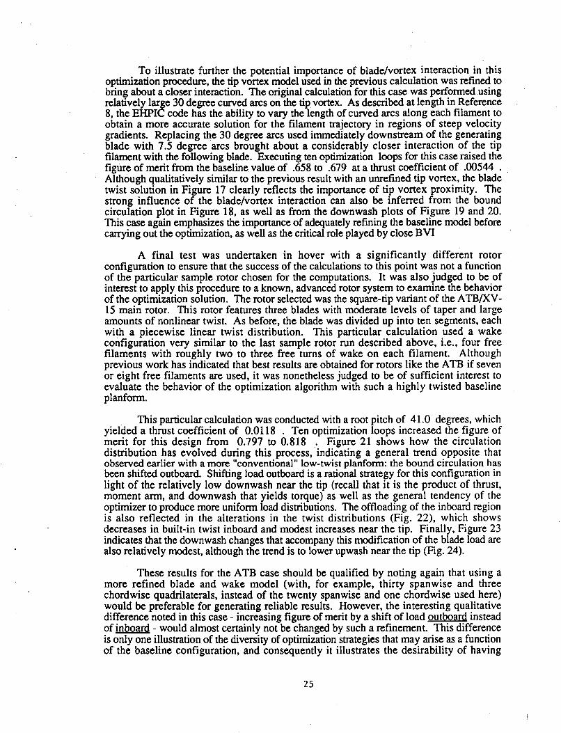
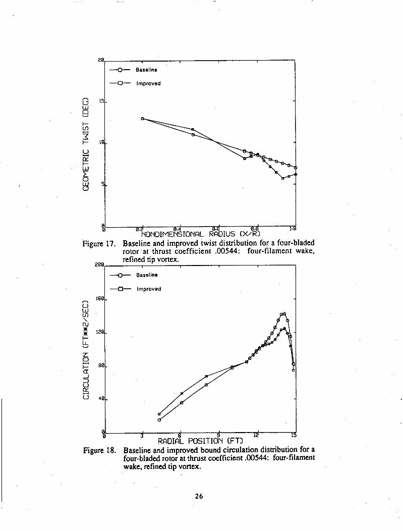
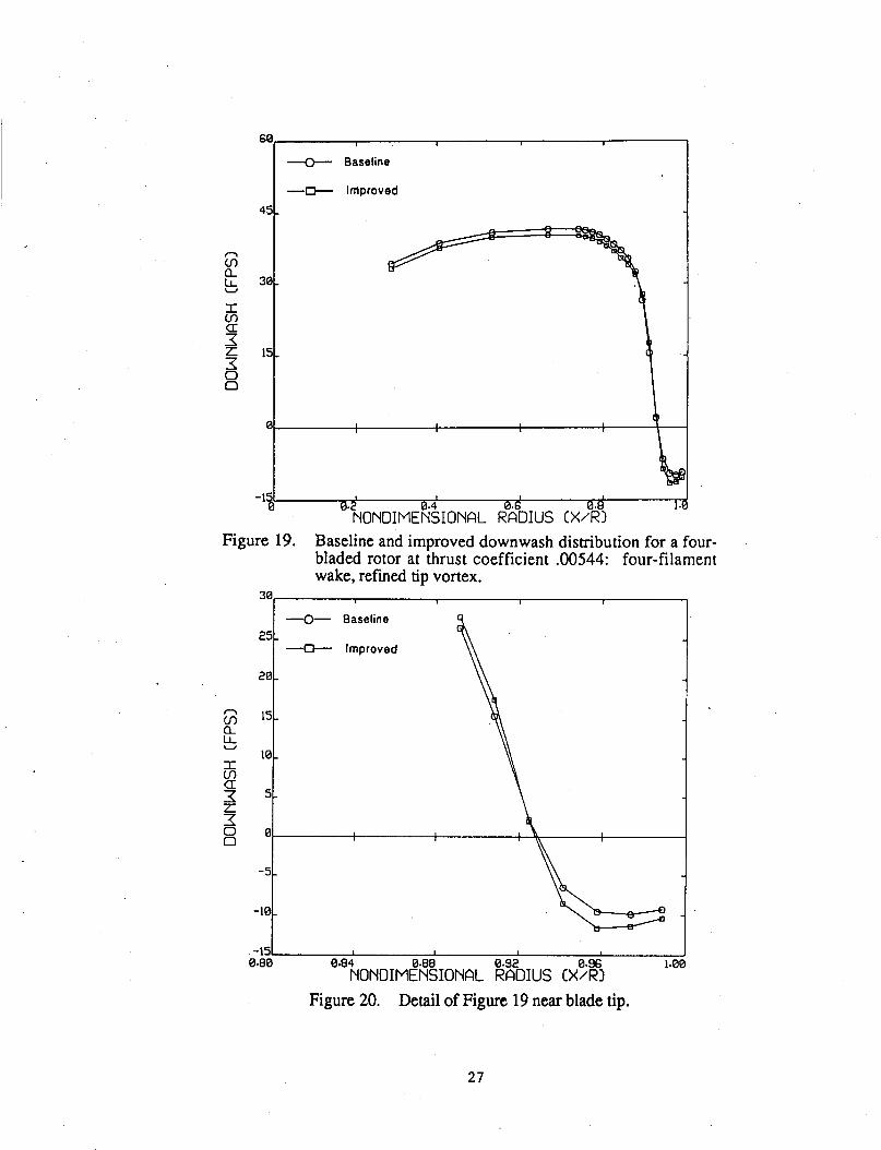
To illustrate further the potential importance of bladehortex interaction in this optimization procedure, the tip vortex model used in the previous calculation was refined to bring about a closer interaction. The original calculation for this case was performed using relatively large 30 degree curved arcs on the tip vortex. As described at length in Reference 8, the EHPIC code has the ability to vary the length of curved arcs along each filament to obtain a more accurate solution for the filament trajectory in regions of steep velocity gradients. Replacing the 30 degree arcs used immediately downstream of the generating blade with 7.5 degree arcs brought about a considerably closer interaction of the tip filament with the following blade. Executing ten optimization loops for this case raised the figure of merit from the baseline value of .658 to .679 at a thrust coefficient of .00544 . Although qualitatively similar to the previous result with an unrefined tip vortex, the blade twist solution in Figure 17 clearly reflects the importance of tip vortex proximity. The strong influence of the bladehortex interaction can also be inferred from the bound circulation plot in Figure 18, as well as from the downwash plots of Figure 19 and 20. This case again emphasizes the importance of adequately refining the baseline model before carrying out the optimization, as well as the critical role played by close BVI
A final test was undertaken in hover with a significantly different rotor configuration to ensure that the success of the calculations to this point was not a function of the particular sample rotor chosen for the computations. It was also judged to be of interest to apply this procedure to a known, advanced rotor system to examine the behavior of the optimization solution. The rotor selected was the square-tip variant of the ATBKV- 15 main rotor. This rotor features three blades with moderate levels of taper and large amounts of nonlinear twist. As before, the blade was divided up into ten segments, each with a piecewise linear twist distribution. This particular calculation used a wake configuration very similar to the last sample rotor run described above, i.e., four free filaments with roughly two to three free turns of wake on each filament. Although previous work has indicated that best results are obtained for rotors like the ATB if seven or eight free filaments are used, it was nonetheless judged to be of sufficient interest to evaluate the behavior of the optimization algorithm with such a highly twisted baseline planform.
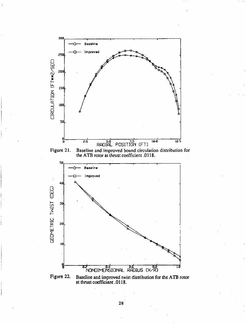
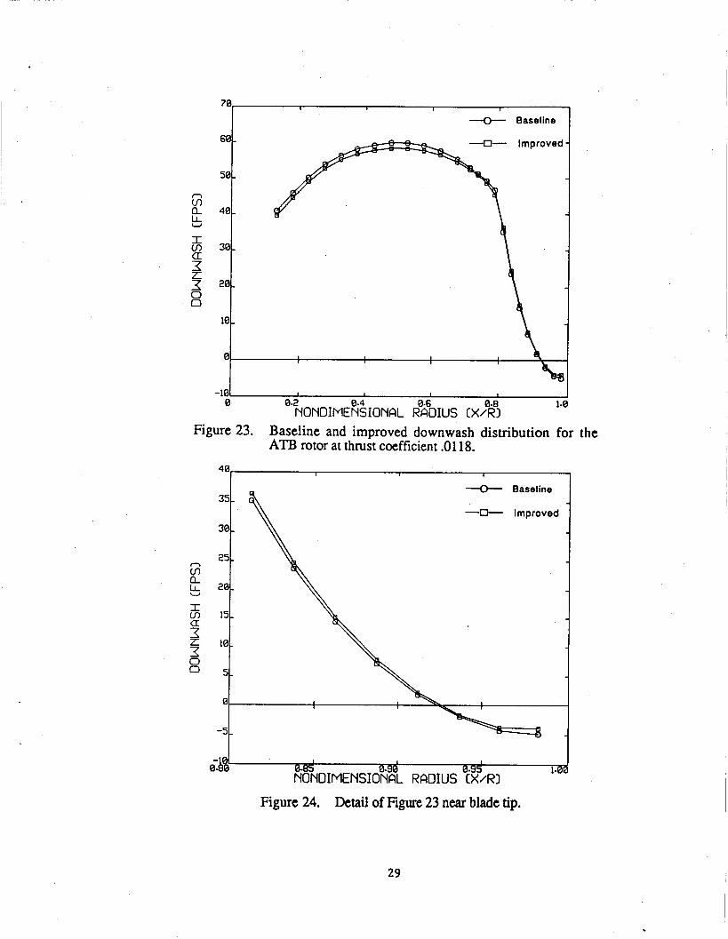
This particular calculation was conducted with a root pitch of 41 .O degrees, which yielded a thrust coefficient of 0.01 18 . Ten optimization loops increased the figure of merit for this design from 0.797 to 0.818 . Figure 21 shows how the circulation distribution has evolved during this process, indicating a general trend opposite that observed earlier with a more llconventionall' low-twist planform: the bound circulation has been shifted outboard. Shifting load outboard is a rational strategy for this configuration in light of the relatively low downwash near the tip (recall that it is the product of thrust, moment arm, and downwash that yields torque) as well as the general tendency of the optimizer to produce more uniform load distributions. The offloading of the inboard region is also reflected in the alterations in the twist distributions (Fig. 22). which shows decreases in built-in twist inboard and modest increases near the tip. Finally, Figure 23 indicates that the downwash changes that accompany this modification of the blade load are also relatively modest, although the trend is to lower upwash near the tip (Fig. 24).
These results for the ATB case should be qualified by noting again that using a more refined blade and wake model (with, for example, thirty spanwise and three chordwise quadrilaterals, instead of the twenty spanwise and one chordwise used here) would be preferable for generating reliable results. However, the interesting qualitative difference noted in this case - increasing figure of merit by a shift of load outboard instead of inboa4 - would almost certainly not be changed by such a refinement. This difference is only one illustration of the diversity of optimization strategies that may arise as a function of the baseline configuration, and consequently it illustrates the desirability of having
25
U Baseline
* Improved
160
-c-, Baseline
-0- Improved
-
I 1 I
3 6 9 12 RADIAL POSITION CFTI
i Figure 18. Baseline and improved bound circulation distribution for a
four-bladed rotor at thrust coefficient .00544: four-filament wake, refined tip vortex.
26
+ Baseline
-0- Improved
45
-151 I I 1 I
0 '.ZNONDIME~$IONAL RBZOIUS CX%I 1.
Figure 19. Baseline and improved downwash dismbution for a four- bladed rotor at thrust coefficient .00544: four-filament wake, refined tip vortex.
G s a I m 4 f 0 0
-0- Baseline
-C+- Improved 25 -
20 -
15 -
10 -
5 -
h-l -1st I I I
0.80 0.84 NONDIM?~!IONAL KOIUS (x%i 1.01
Figure 20. Detail of Figure 19 near blade tip.
27
-Q- Baseline
1 I
0 2.5 10.0 12. 01
RADI?T POSIT[O% CFTI
I --e Baseline
Figure 21. Baseline and improved bound circulation distribution for the ATB rotor at thrust coefficient .0118.
I 4- Improved I
I 1 I
1. @.~NONOIME%IONAL RB~OIUS cxA3 Figure 22. Baseline and improved twist distribution for the ATl3 rotor
at thrust coefficient .0118.
28
G k a
I cn 4 f 0 0
20
10
78 r I
-0- Baseline
-
-
301 i
-101 I I I I
0 0.2 NONDIME~~IONAL &%IUS cx%? 1-1
Figure 23. Baseline and improved downwash distribution for the ATB rotor at thrust coefficient .0118.
-0- Baseline
-0- Improved
Figure 24. Detail of Figure 23 near blade tip.
29
available a flexible, generally applicable optimization analysis such as the one developed here.
4.2 Sample Case in Axial Flight
The baseline EHPIC calculation is applicable to rotors in axial flight as well as those in hover. It is relevant to demonstrate the capabilities of the optimization analysis developed here in climb, since many current helicopters have demanding specifications set on their climb performance. The general issue to be addressed here is how the improved blade design for a given rotor differs if the desired flight condition is specified to be in climb rather than in hover. Consider in particular the four bladed "generic" rotor used in the previous section. Recall that the hover case with two free filaments was able to produce a twist distribution with a five-point increment in figure of merit at a thrust coefficient of 0.00574 and that the final design showed considerable sensitivity to the proximity of tip vortices passing beneath following blades. It was resolved to examine the behavior of the improved solution with the rotor in climb at 900 fpm ( 274 dmin.), operating at the same thrust level.
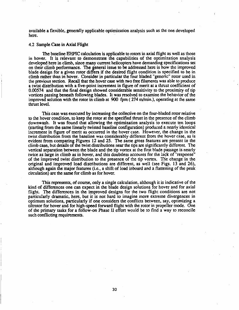
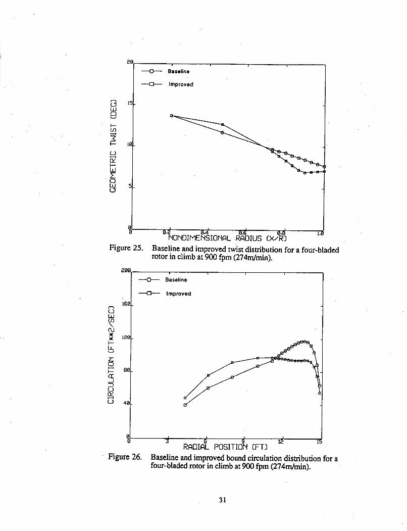
I This case was executed by increasing the collective on the four-bladed rotor relative to the hover condition, to keep the rotor at the specified thrust in the presence of the climb downwash. It was found that allowing the optimization analysis to execute ten loops (starting from the same linearly twisted baseline configuration) produced a nearly identical increment in figure of merit as O C C U K ~ in the hover case. However, the change in the twist distribution from the baseline was considerably different from the hover case, as is evident from comparing Figures 12 and 25. The same gross features are present in the climb case, but details of the twist distributions near the tips are significantly different. The vertical separation between the blade and the tip voxtex at the first blade passage is nearly twice as large in climb as in hover, and this doubtless accounts for the lack of "response" of the improved twist distribution to the presence of the tip vortex. Tlie change in the original and improved load distributions are different, as well (see Figs. 13 and 26), although again the major features (Le., a shift of load inboard and a flattening of the peak circulation) are the same for climb as for hover.
This represents, of course, only a single calculation, although it is indicative of the kind of differences one can expect in the blade design solutions for hover and for axial flight. The differences in the improved designs for the two flight conditions are not particularly dramatic, here, but it is not hard to imagine more extreme divergences in optimum solutions, particularly if one considers the conflicts between, say, optimizing a tiltrotor for hover and for high-speed forward flight with the rotor in propeller mode, One of the primary tasks for a follow-on Phase I1 effort would be to find a way to reconcile such conflicting requirements.
30
ij W 0
I-
U
2 I-
o CL I-
0 W c3
H
!?
I I I
Baseline
-* Improved
160
120
80.
40.
t I I I I
1. 01 0 0 * 2 N ~ ~ ~ ~ ~ ~ % ~ ~ ~ ~ ~ RB~OIUS cx;RY
Figure 25. Baseline and improved twist distribution for a four-bladed rotor in climb at 900 fpm (2744min).
8 W m \
m 2 t- !5 L
c a: -I 3 o o
E!
-0- Baseline
4- Improved
01 I I I I
0 3 6 9 12 RADIAL POSITION CFTI
Figure 26. Baseline and improved bound circulation distibution for a four-bladed rotor in climb at 900 fpm (274dmin).
31

5. CONCLUSIONS AND RECOMMENDATIONS FOR FUTURE WORK
The primary aim of this effort has been to establish that a linear optimization algorithm could be successfully coupled to the quasi-linear wake relaxation technique that forms the technical foundation of the EHPIC hover performance code. This coupling was indeed found to be possible once a suitable expansion of the matrix of linearized influence coefficients in the coupled blade/wake relaxatioq was accomplished, and new coefficients had been derived for a linearized equation governing perturbations in power (the objective function for the optimization analysis) and the thrust. The derivation of these additional coefficients was considerably simplified because of the preexisting blade-on-blade and wake-on-blade influence coefficients in the EHPIC analysis, as well as by the coding in the original hover performance software.
Using the flow tangency conditions on the blade and in the wake to impose equality constraints on the expanded system of equations and specifying inequality constraints to bound the perturbations imposed on the system during a given step in the analysis, it was found that the linear optimization routine (derived from a general simplex formulation) could be invoked to predict a design change that would produce a reduction in the power required by the rotor at constant thrust. By suitable exploitation of the perturbations in blade design, wake geometry, and bound circulation computed in the optimization program, a given baseline blade design could be modified to an adjacent solution in design space while still satisfying all appropriate flow tangency conditions; thus, computationally expensive calls to the original hover relaxation routine could be avoided, leading to an efficient treatment of a complex problem that retains a physically accurate model of the flow.
The results of the various sample calculations discussed above demonstrate the success of this coupled algorithm in action. In several computations ranging from simplified model problems to more realistic performance calculations this preliminary version of the optimization analysis has proved its ability to achieve reliable convergence to configurations with substantially improved performance relative to their respective baseline cases. Even within the context of the current analysis, though, a number of issues have been raised that are clear candidates for examination in follow-on work. Prominent among these is a systematic examination of the appropriate choices for the inequality constraints used within the optimization analysis. The current choices may err on the side of conservatism as a result of concern to keep the linearized analysis from foundering on the fundamental nonlinearity of the system; permitting wider variations in design variables could reduce the computation time required to reach a specified improvement in performance. This, along with streamlined calculations of some design variable derivatives, would considerably enhance computational efficiency. In addition, careful attention should be paid to the selection of the level of refinement in the blade design, so as to avoid missing promising avenues for design improvements through excessively coarse resolution of the blade design (e.g., using segments too large to properly resolve the twist distribution on the blade).
These issues, while important, pertain fundamentally to numerical checks on the methods developed here. These methods are intended to form the foundation of a more comprehensive and robust optimization analysis, and reaching this goal will require not only revisions in major features of the current model but also the development of substantive new techniques. Among the revisions and improvements that are required to carry out follow-on work is 'the addition of new design variables (e.g., the chord distribution, tip sweep, anhedral) that are candidates for consideration in advanced blade configurations. The consideration of these new quantities in turn suggests improvements
32
in the level of refinement in the aerodynamic modelling of the blade. The current vortex lattice model, for example, has the potential for developing local inaccuracies in the load distribution at kinks in swept planforms; the incorporation of new elements in the blade lifting surface model (such as continuous vortex sheets in place of quadrilaterals) is both easily accomplished in the context of the current relaxation method and a potentially important contributor to the accuracy of the solution method. Finally, another prominent candidate for upgrading is the current lift model on the blade, which may permit nonphysical lift coefficients to exist in some operating conditions; proper account must be taken of stall - both in terms of thrust and profile drag - if realistic new designs are to be produced.
Along with these extensions of current practice, entirely new tools and procedures can and should be brought to bear in the development of a comprehensive optimization code. First, design constraints drawn from other flight conditions must be included in the hover optimization analysis. The results of the sample problems discussed above indicated that the constraints imposed to this point in hover did not truly bound the design; significant amounts of twist can be added to the blade outboard to improve hover performance, but such distributions may well adversely affect the rotor performance in climb, forward flight (for helicopters), or propeller mode (for tiltrotors). The sample computation for a rotor in climb discussed in Section 4 in fact illustrated the different results that can arise depending on the flight condition chosen for optimization. It is possible to consider explicitly coupling the hover performance optimization to optimization for climb or propeller mode design points, given that the fundamental solution method can address these flight conditions directly. To take account of forward flight requirements, implicit constraints can be imposed in the form of bounds on the total allowable levels of change in twist (or other design variables) over the important segments of the rotor span.
The incorporation of the linear optimization routine into the current hover analysis also presents an opportunity for a fundamental improvement in an important aspect of the baseline EHPIC analysis. Although not exercised extensively in this effort, one of the significant latent strengths of the influence coefficient solution method is its ability to selectively refine the size of the curved arcs used to model the vortex wake. This allows high-resolution flow models to be used in regions of rapid evolution (e.g., tip vortex roll- up, BVI, etc.) while retaining coarse, efficient models in the far wake. A significant problem with the existing analysis, though, is that the simple relaxation algorithm currently used in the EHPIC code is insufficiently robust to reliably guarantee convergence of some highly-refined configurations, a circumstance that limits its applicability in cases involving, for example, significant three-dimensional wake rollup effects. The possibility exists now to use the simplex algorithm that was brought into play for the optimization analysis to address this problem. The simplex algorithm itself could be used to carry out the relaxation of the wake by minimizing an appropriately chosen objective function (say, a sum of the squares of crossflow and downwash velocities). A particular strength of this approach would be the ability to explicitly constrain the changes in wake position that occur at each step, thus ensuring that "kinks" do not develop in the small curved arcs used in regions of high resolution; distortions of this type have seriously hampered convergence in some calculations carried out to date.
The sample problems executed above give ample evidence of the potential importance of close blade/vortex interaction in determining the blade loads and, implicitly, the improved blade designs. The refined wake analysis and lifting surface singularities discussed above will, of course, improve the resolution of such interactions. However, new techniques are available to obtain high-resolution predictions of such close interactions without the computational expense of retaining a large number of evaluation points. This is possible through the use of a generic procedure known as analyticaVnumenca1 matching,
33
which corrects a low-resolution solution for the flow in a particular region (obtained with a set of relatively coarsely spaced evaluation points) with an appropriate analytical result to produce high local resolution. A previous application of this general approach is described in Reference 23, and a modified and extended version of this method incorporating lifting surface effects could be introduced to improve the modelling of tip aerodynamics, particularly those cases entailing close encounters.
Finally, it would be appropriate in follow-on work to reassess the choice of a linear optimization algorithm for application to this topic. The Phase I approach is judged to have been an appropriate choice for a short-term technology demonstration and has clearly enjoyed considerable success in obtaining twist distributions that improve performance substantially. However, the introduction other design varibles that generate more complex relationships between the performance and the design could well alter this situation. It is not difficult to envision complicated topographies of performance in design space that would be difficult to resolve efficiently without a nonlinear optimization routine. Thus, one of the priorities in further work in this area should be to evaluate candidate nonlinear algorithms for coupling to the EHPIC code in the same general manner as outlined here.
In summary, the foundation has been laid for the development of a comprehensive and efficient performance optimization routine for lifting rotors in hover and axial flight. A preliminary version of this analysis has been successfully applied to representative sample problems, demonstrating the soundness of the basic approach. Both revisions of existing models and new techniques have been identified that have the potential for converting this baseline routine into generally applicable tool for researchers and designers in both industry and government.
34
6. REFERENCES
1.
2.
3.
4.
5.
6 .
7.
8.
9.
10.
11.
12.
13.
14.
15.
Landgrebe, A.J.: "An Analytical Method for Predicting Rotor Wake Geometry." Journal of the American Helicopter Society Vol. 14, No. 4, October 1969.
Kocurek, J.D. and Tangler, J.L.: "A Prescribed Wake Lifting Surface Analysis." Journal of the American Helicopter Society Vol. 22, No. 1, January 1977.
Egolf, T.A. and Landgrebe, A.J.: "Helicopter Wake Geometry and Its Influence in Forward Flight." NASA CR 3726, October 1983.
Harris, F.D.: "Rotary Wing Aerodynamics - Historical Perspective and Important Issues." Proceedings of the National Specialists' Meeting on Aerodynamics and Aeroacoustics, Arlington, Texas, February 1987.
Landgrebe, A.J.: "An Analytical and Experimental Investigation of Helicopter Rotor Hover Performance and Wake Geometry Characteristics." USAAMRDL TR 71-24, June 1971.
Scully, M.P.: "Computation of Helicopter Rotor Wake Geometry and Its Influence on Rotor Harmonic Airloads." MIT ASRL TR 178-1, March 1975.
Bliss, D.B., Wachspress, D.A. and Quackenbush, T.R.: "A New Approach to the Free Wake Problem for Hovering Rotors." Proceedings of the 41st Annual Forum of the American Helicopter Society, May 1985.
Quackenbush, T.R., et al.: "Free Wake Analysis of Hover Performance Prediction Using an Influence Coefficient Method", NASA CR 4150, 1988.
Bliss, D. B. ,Quackenbush, T.R., and Bilanin, A.J.: "A New Methodology for Helicopter Free Wake Analyses." Proceedings of the 39th Annual Forum of the American Helicopter Society, May 1987.
Bliss, D. B., Teske, M.E., and Quackenbush, T.R.: "A New Methodology for Free Wake Analyses Using Curved Vortex Elements." NASA CR 3958.
Ashley, H.: "On Making Things the Best - Aeronautical Uses of Optimization." Journal of Aircraft Vol. 19, No. 1, 1982.
Miura, H.: "Applications of Numerical Optimization Methods to Helicopter Design Problems - A Survey." Vertica ,Vol. 9, No. 2, 1985.
Bennett, R.L.: Problems." Vertica Vol. 7, No. 3, 1983.
"Application of Optimization Methods to Rotor Design
Stepniewski, W.Z. and Kalmbach, C.F.: "Multivariable Search and Its Applications to Aircraft Design Optimization." Aeronautical Journal, Vol. 74, 1970.
Davis, M. W ., and Weller, W.H: "Application of Design Optimization Techinques to Rotor Dynamics Problems", Journal of the American Helicopter Society, Vol. 33, No. 3, July 1988.
35
16
17.
18.
19.
20.
21.
22.
23.
24.
Bennett, R.L.: "Optimum Structural Design", Proceedings of the 38th Annual F o m of the American Helicopter Society, Anaheim, Calif., May 1982.
Friedmann, P.P.: "Application of Modern Structural Optimization to Vibration Reduction in Rotorcraft." Vertica Vol. 9, No. 4, 1985.
Moffitt, R.C. and Bissell, J.R.: "Theory and Application of Optimum Airloads to Rotors in Hover and Forward Flight." Proceedings of the 38th Annual Forum of the AHS, May 1982.
Nagashima, T. and Nakaniski, K.: "Optimum Performance and Wake Geometry of a Coaxial Rotor in Hover." Vertica, Vol. 7, No. 3, 1983.
Chung, S.-Y.: "Formal Optimization of Hover Performance Using Free Wake Lifting Surface Theory," Ph.D. Thesis, Dept. of Aeronautics & Astronautics, Massachusetts Institute of Technology, 1986.
Walsh, J.L., Bingham, G.J., and Riley, M.F.: "Optimization Methods Applied to the Aerodynamic Design of Helicopter Rotor Blades", Journal of the American Helicopter Society, Vol. 32, No. 4, Oct. 1987.
Press, W.H., et al.: Numerical Rec iDU, Cambridge University Press, 1986.
Quackenbush, T.R., and Bliss, D.B.: "Free Wake Calculation of Rotor Flow Fields for Interactional Aerodynamics", Proceedings of the 44th Annual Forum of the American Helicopter Society, Washington, D.C., June 1988.
Felker, F.F., Quackenbush, T.R., Bliss, D.B, and Light, J.L: "Comparisons of Predicted and Measured Rotor Performance Using a New Free Wake Method", Proceedings of the 44th Annual Forum of the American Helicopter Society, Washington, D.C., June 1988.
36
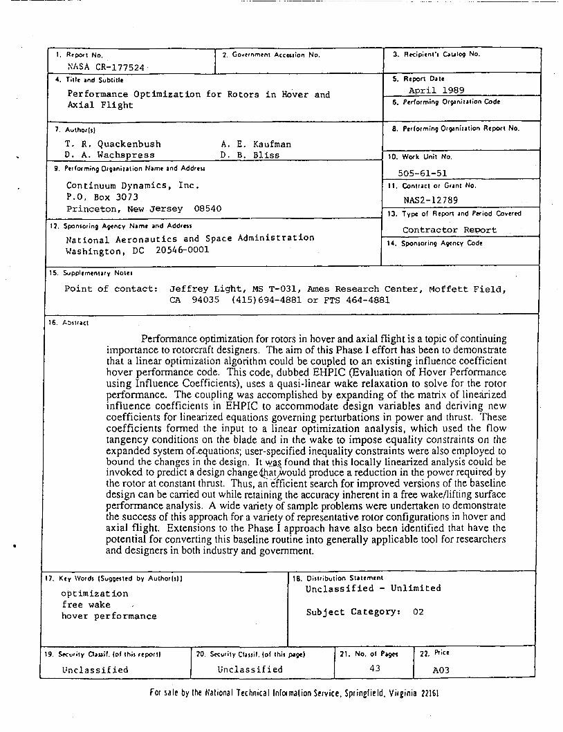
S k S A CR-177524 4. Tit le and Subtitle
3. Rrcipicnt's Gulag NO. I. Rtpoci No. I ?. Covcrnmrnt Accession No. I 5. Repon Date
7. Author(,)
T. R . Quackenbush A . E. Kaufman D . A. Wachspress D . B. Bliss ,
Performance O p t i m i z a t i o n f o r Rotors i n Hover and Axial F l i g h t
8. Performing Orgartilation Report NO.
10. Work Unit No.
Continuum Dynamics, I n c . P.O. Box 3073 P r i n c e t o n , New J e r s e y 08540
12. Sponsoring Agency Name and Address
N a t i o n a l A e r o n a u t i c s and Space Adminis t ra t ion Washington, DC 20546-0001
9. Performing Organization Name and Addreu
11. Contract or Grant No.
NAS2- 12 7 89 13. Type of Repon and Period Covered
C o n t r a c t o r R e p o r t 14 . Sponsoring Agency Code
I 505-61-51
I I
9. Secucity C l a u i f . (of this repor t ) 70. Security Classil. (of this pge) 21. No. of Pages 22. Rice
U n c l a s s i f i e d U n c l a s s i f i e d 43 A03
7. Key Words (Suggested by Authorls)) I 18. Oistribution Statement 1 o p t i m i z a t i o n f r e e wake ,
hover per formance
I U n c l a s s i f i e d - Unl imi ted
For sale by Ihe National Technical Informalion Service. Sprinelield. Virginia 22161