ROTOR LEVITATION AND VIBRATION CONTROL OF HYBRID POLE … · The validity of the proposed control...
11
International Journal of Innovative Computing, Information and Control ICIC International c ⃝2018 ISSN 1349-4198 Volume 14, Number 2, April 2018 pp. 671–681 ROTOR LEVITATION AND VIBRATION CONTROL OF HYBRID POLE BSRM USING FUZZY SLIDING MODE CONTROLLER Polamraju Venkata Subrahmanya Sobhan 1 Gundavarapu Venkata Nagesh Kumar 2 and Pulipaka Venkata Ramana Rao 3 1 Department of Electrical and Electronics Engineering Vignan’s Foundation for Science, Technology and Research Vadlamudi, Guntur 522213, India [email protected] 2 Department of Electrical and Electronics Engineering Vignan’s Institute of Information Technology Visakhapatnam 530049, India [email protected] 3 Department of Electrical and Electronics Engineering Acharya Nagarjuna University Guntur 522510, India pvr [email protected] Received June 2017; revised October 2017 Abstract. Rotor vibration control during startup, acceleration and deceleration phases is one of key problems besides stable levitation, in high-speed applications of bearingless switched reluctance motor (BSRM). The use of linear control strategies alone is not ef- fective in suppressing vibration due to residual unbalance and external disturbance. This paper presents implementation of a nonlinear control method by integrating the features of fuzzy logic and the sliding mode control (SMC) to minimize the rotor vibration and eccentricity error of BSRM. The application of fuzzy SMC with the independent control of the radial force and rotational force guarantees stable levitation as well as the vibration reduction and the same is demonstrated with experimental results. Keywords: BSRM, Radial force control, Fuzzy sliding mode controller, Rotor eccen- tricity 1. Introduction. High speed motors working in harsh environments such as high tem- peratures, radiation and poisonous substances are limited because of motor breakdown due to vibrations of mechanical bearings. The concept of magnetic bearings is an alternative to the issues of slide or ball bearings because of its advantages of friction-free, negligible thermal problems, and lubrication free. A magnetic bearing is an electro-mechanical ele- ment which levitates the rotor magnetically without any mechanical contact between the stator and rotor [1,2]. A bearingless motor integrates the functions of rotation and noncontact levitation and they are employed in high-speed and high-purity areas such as semiconductor, radioactive, space equipment pharmaceutical and medical industry [3-8]. Due to the single-excited, doubly salient structure and presence of significant magnetic force between rotor and stator poles, the switched reluctance motors are ideally suitable as bearingless motors. The non uniform and short air-gap adequately generate torque and radial force to levitate the rotor [9]. 671
Transcript of ROTOR LEVITATION AND VIBRATION CONTROL OF HYBRID POLE … · The validity of the proposed control...

International Journal of InnovativeComputing, Information and Control ICIC International c⃝2018 ISSN 1349-4198Volume 14, Number 2, April 2018 pp. 671–681
ROTOR LEVITATION AND VIBRATION CONTROL OF HYBRIDPOLE BSRM USING FUZZY SLIDING MODE CONTROLLER
Polamraju Venkata Subrahmanya Sobhan1
Gundavarapu Venkata Nagesh Kumar2
and Pulipaka Venkata Ramana Rao3
1Department of Electrical and Electronics EngineeringVignan’s Foundation for Science, Technology and Research
Vadlamudi, Guntur 522213, [email protected]
2Department of Electrical and Electronics EngineeringVignan’s Institute of Information Technology
Visakhapatnam 530049, [email protected]
3Department of Electrical and Electronics EngineeringAcharya Nagarjuna University
Guntur 522510, Indiapvr [email protected]
Received June 2017; revised October 2017
Abstract. Rotor vibration control during startup, acceleration and deceleration phasesis one of key problems besides stable levitation, in high-speed applications of bearinglessswitched reluctance motor (BSRM). The use of linear control strategies alone is not ef-fective in suppressing vibration due to residual unbalance and external disturbance. Thispaper presents implementation of a nonlinear control method by integrating the featuresof fuzzy logic and the sliding mode control (SMC) to minimize the rotor vibration andeccentricity error of BSRM. The application of fuzzy SMC with the independent controlof the radial force and rotational force guarantees stable levitation as well as the vibrationreduction and the same is demonstrated with experimental results.Keywords: BSRM, Radial force control, Fuzzy sliding mode controller, Rotor eccen-tricity
1. Introduction. High speed motors working in harsh environments such as high tem-peratures, radiation and poisonous substances are limited because of motor breakdown dueto vibrations of mechanical bearings. The concept of magnetic bearings is an alternativeto the issues of slide or ball bearings because of its advantages of friction-free, negligiblethermal problems, and lubrication free. A magnetic bearing is an electro-mechanical ele-ment which levitates the rotor magnetically without any mechanical contact between thestator and rotor [1,2].
A bearingless motor integrates the functions of rotation and noncontact levitation andthey are employed in high-speed and high-purity areas such as semiconductor, radioactive,space equipment pharmaceutical and medical industry [3-8]. Due to the single-excited,doubly salient structure and presence of significant magnetic force between rotor andstator poles, the switched reluctance motors are ideally suitable as bearingless motors.The non uniform and short air-gap adequately generate torque and radial force to levitatethe rotor [9].
671
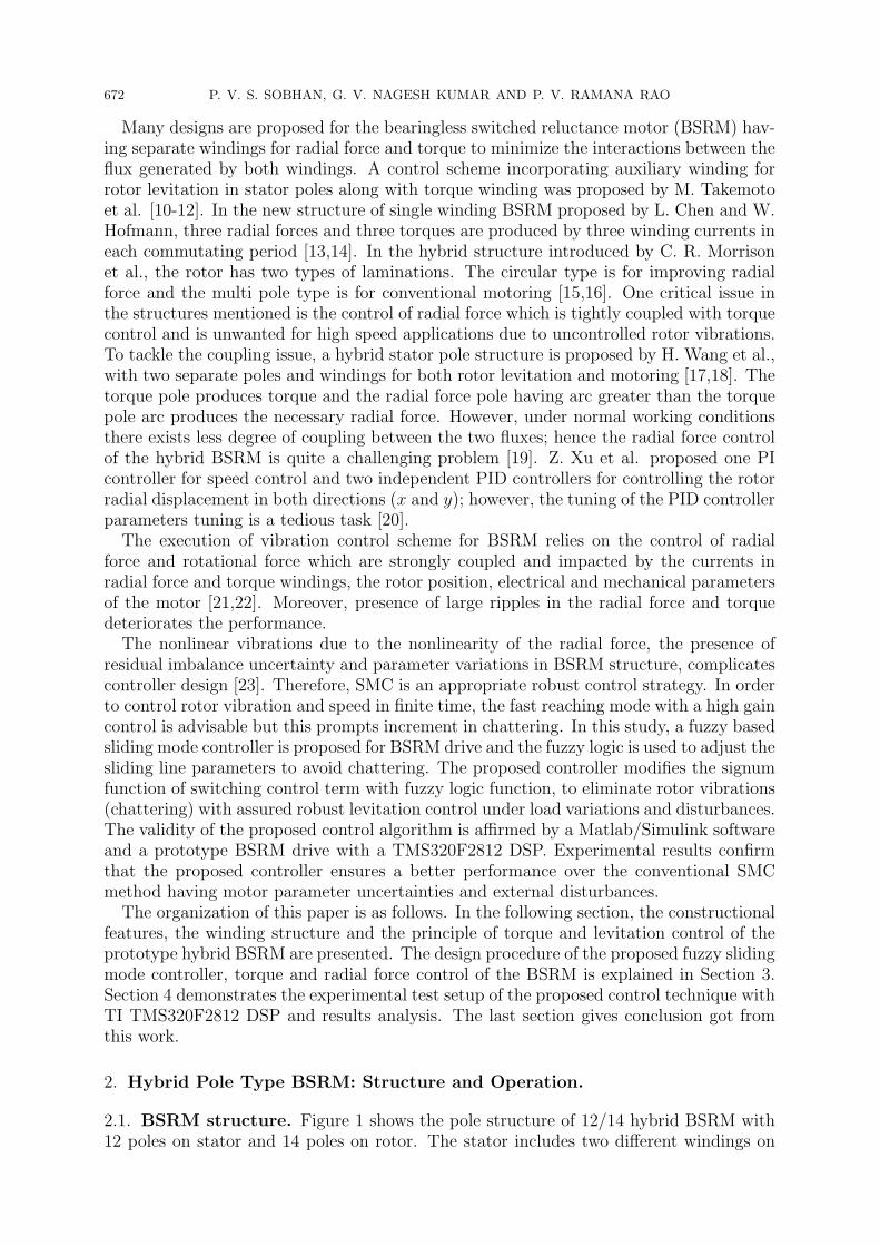
672 P. V. S. SOBHAN, G. V. NAGESH KUMAR AND P. V. RAMANA RAO
Many designs are proposed for the bearingless switched reluctance motor (BSRM) hav-ing separate windings for radial force and torque to minimize the interactions between theflux generated by both windings. A control scheme incorporating auxiliary winding forrotor levitation in stator poles along with torque winding was proposed by M. Takemotoet al. [10-12]. In the new structure of single winding BSRM proposed by L. Chen and W.Hofmann, three radial forces and three torques are produced by three winding currents ineach commutating period [13,14]. In the hybrid structure introduced by C. R. Morrisonet al., the rotor has two types of laminations. The circular type is for improving radialforce and the multi pole type is for conventional motoring [15,16]. One critical issue inthe structures mentioned is the control of radial force which is tightly coupled with torquecontrol and is unwanted for high speed applications due to uncontrolled rotor vibrations.To tackle the coupling issue, a hybrid stator pole structure is proposed by H. Wang et al.,with two separate poles and windings for both rotor levitation and motoring [17,18]. Thetorque pole produces torque and the radial force pole having arc greater than the torquepole arc produces the necessary radial force. However, under normal working conditionsthere exists less degree of coupling between the two fluxes; hence the radial force controlof the hybrid BSRM is quite a challenging problem [19]. Z. Xu et al. proposed one PIcontroller for speed control and two independent PID controllers for controlling the rotorradial displacement in both directions (x and y); however, the tuning of the PID controllerparameters tuning is a tedious task [20].
The execution of vibration control scheme for BSRM relies on the control of radialforce and rotational force which are strongly coupled and impacted by the currents inradial force and torque windings, the rotor position, electrical and mechanical parametersof the motor [21,22]. Moreover, presence of large ripples in the radial force and torquedeteriorates the performance.
The nonlinear vibrations due to the nonlinearity of the radial force, the presence ofresidual imbalance uncertainty and parameter variations in BSRM structure, complicatescontroller design [23]. Therefore, SMC is an appropriate robust control strategy. In orderto control rotor vibration and speed in finite time, the fast reaching mode with a high gaincontrol is advisable but this prompts increment in chattering. In this study, a fuzzy basedsliding mode controller is proposed for BSRM drive and the fuzzy logic is used to adjust thesliding line parameters to avoid chattering. The proposed controller modifies the signumfunction of switching control term with fuzzy logic function, to eliminate rotor vibrations(chattering) with assured robust levitation control under load variations and disturbances.The validity of the proposed control algorithm is affirmed by a Matlab/Simulink softwareand a prototype BSRM drive with a TMS320F2812 DSP. Experimental results confirmthat the proposed controller ensures a better performance over the conventional SMCmethod having motor parameter uncertainties and external disturbances.
The organization of this paper is as follows. In the following section, the constructionalfeatures, the winding structure and the principle of torque and levitation control of theprototype hybrid BSRM are presented. The design procedure of the proposed fuzzy slidingmode controller, torque and radial force control of the BSRM is explained in Section 3.Section 4 demonstrates the experimental test setup of the proposed control technique withTI TMS320F2812 DSP and results analysis. The last section gives conclusion got fromthis work.
2. Hybrid Pole Type BSRM: Structure and Operation.
2.1. BSRM structure. Figure 1 shows the pole structure of 12/14 hybrid BSRM with12 poles on stator and 14 poles on rotor. The stator includes two different windings on

ROTOR LEVITATION AND VIBRATION CONTROL OF HYBRID POLE BSRM 673
poles, i.e., four windings Pxp, Pxn, Pyp and Pyn for radial force generation with currentsixp, ixn, iyp and iyn respectively and the other eight windings are for torque generation tooperate as a two phase SRM. Four windings PA1-PA4 are connected in series and excitedsimultaneously to form phase A and similarly, windings PB1-PB4 form phase B. The rotorpoles are symmetrically spaced without windings. The four radial force poles and thetwo torque winding phases are placed coordinately and diagonally respectively and all areexcited individually. This hybrid pole structure totally decouples the radial force controlfrom torque control because of the negligible and undesirable torque produced by radialforce poles.
Figure 1. Basic structure of 12/14 BSRM
2.2. Torque control. The electromagnetic torque produced in BSRM mainly dependson winding inductance profile and expressed as
T =1
2i2
dL
dθ(1)
where i and L are current and inductance of torque or radial force windings, and θ isthe rotor position. In radial force windings, the torque contribution is negligible becauseof constant inductance profile for constant current; hence, the torque is independent ofradial force current. In the torque winding, due to large variation in the inductance profilefrom aligned to unaligned position, the slope of inductance is very large; hence, the nettorque on the rotor is due to torque windings only.
The torque, thereby the rotor speed control can be achieved by synchronizing the phasewinding currents iA and iB with the rotor position by controlling the PWM duty ratio toturn on and turn off of switches in asymmetric converters of corresponding torque windingphase as shown in Figure 2.
2.3. Radial force control. The generated radial force in the x-direction is due to thecurrents ixp and ixn, and in y-direction is due to currents iyp and iyn flowing in fourradial force poles Pxp, Pxn, Pyp and Pyn. The radial force on the rotor in any position

674 P. V. S. SOBHAN, G. V. NAGESH KUMAR AND P. V. RAMANA RAO
Figure 2. Asymmetric converter for torque windings
Figure 3. Asymmetric converter for radial force windings
and directions (+x, −x, +y and −y) can be controlled by controlling ixp, ixn, iyp andiyn independently. Based on the rotor eccentric position, any two levitation windings areselected accordingly and controlled independently by asymmetric bridge converter shownin Figure 3.
3. Fuzzy Sliding Mode Control. The sliding mode control strategy with features suchas robustness, quick convergence and high control precision, is widely implemented indifferent systems. However, its significant drawback is the chattering problem for practicalapplications. Fuzzy control (FC) is especially reasonable for those systems with modelingcomplexities and uncertainties. The extensive uncertainties cause high chattering andto eliminate it the SMC need high switching gain with an increased boundary limits.However, the continuous increase in the boundary limits leads to ineffective sliding modesystem. The alternative control scheme is to combine the effects of fuzzy control andSMC known as FSMC to have an effective control.
3.1. Sliding mode control. The SMC strategy utilizes discontinuous control to drivestate trajectories towards a particular hyperplane in the state space, and to keep themup sliding on the hyperplane until stable equilibrium state is reached.
An nth-order uncertain nonlinear system is represented as:
xi = xi+1
xn = f(x) + ∆f(x) + η(t) + g(x)u(t)y = x1
(2)

ROTOR LEVITATION AND VIBRATION CONTROL OF HYBRID POLE BSRM 675
where x =[
x1 x2 . . . xn
]T=[
x x . . . x(n−1)]T
is the state vector, u(t) is the
control signal, y = x1 is the system output, f(x) and g(x) are nonlinear functions, ∆f(x)is the uncertainty of unmodeled dynamics and η(t) is the disturbance.∥∥∥∆f(x)
∥∥∥ ≤ ε and ∥η(t)∥ ≤ γ (3)
where ε, γ are positive constants.
The desired state trajectory is defined by xTr =
[xr xr . . . x
(n−1)r
], then the track-
ing error is defined by e = x − xr =[
e e . . . e(n−1)]
=[
e1 e2 . . . en
]and
en = x(n) − x(n)r = f(x) + ∆f(x) + η(t) + g(x)u(t) − x(n)
r (4)
The sliding function is defined as
s =n−1∑i=1
ki ei + en (5)
where ki, i = 1, 2, . . . , n−1 are positive constants which make the zeros of the polynomialλn−1 + kn−1λ
n−2 + · · ·+ k2λ + k1 are in the left side of the imaginary axis in the complexplane and the choice of the coefficients ki is usually determined by the problem underconsideration.
Consider the Lyapunov function as
V =1
2g(x)s2 > 0 (6)
If the designed control input u, such that x tracks xr, according to the Lyapunovstability theory, makes V negative, then the trajectory of the system state would bedriven and gets attracted to s = 0 and continues to slide till the origin is reached ifss < 0.
Differentiation of V along the trajectories gives
V = ss = s
(n−1∑i=1
kiei+1 + f(x) + ∆f(x) + η(t) + g(x)u(t) − x(n)r
)(7)
Then the control input u is chosen as sum of the equivalent control, ueq and switchingcontrol usw which is expressed as u = ueq + usw,
ueq =1
g(x)
(−
n−1∑i=1
ki ei+1 − f(x) − ∆f(x) − η(t) + x(n)r
)(8)
In general the terms ∆f(x) and η(t) are unknown and the modified equivalent controlinput is
ueq =1
g(x)
(−
n−1∑i=1
kiei+1 − f(x) + x(n)r
)(9)
The switched control term is
usw = − ks
g(x)sgn(s) (10)
where
sgn(s) =
|s|s
ors
|s|; s = 0
0; s = 0(11)
and implies that Ltt→∞
s = 0 and hence Ltt→∞
e = 0.
676 P. V. S. SOBHAN, G. V. NAGESH KUMAR AND P. V. RAMANA RAO
The control input (8) with (9) and (10) guarantees the convergence of state trajectoryto the sliding function s = 0 from any initial state.
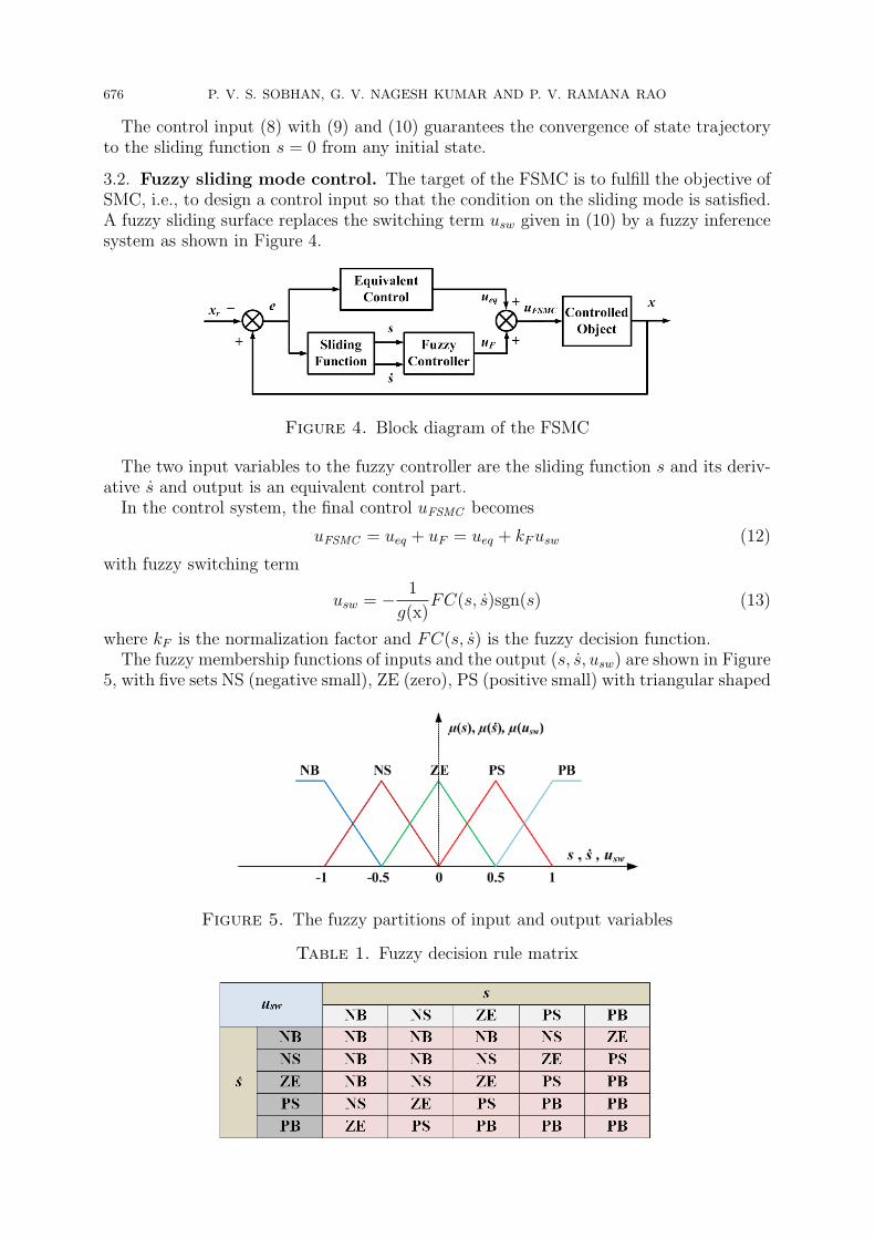
3.2. Fuzzy sliding mode control. The target of the FSMC is to fulfill the objective ofSMC, i.e., to design a control input so that the condition on the sliding mode is satisfied.A fuzzy sliding surface replaces the switching term usw given in (10) by a fuzzy inferencesystem as shown in Figure 4.
Figure 4. Block diagram of the FSMC
The two input variables to the fuzzy controller are the sliding function s and its deriv-ative s and output is an equivalent control part.
In the control system, the final control uFSMC becomes
uFSMC = ueq + uF = ueq + kF usw (12)
with fuzzy switching term
usw = − 1
g(x)FC(s, s)sgn(s) (13)
where kF is the normalization factor and FC(s, s) is the fuzzy decision function.The fuzzy membership functions of inputs and the output (s, s, usw) are shown in Figure
5, with five sets NS (negative small), ZE (zero), PS (positive small) with triangular shaped
Figure 5. The fuzzy partitions of input and output variables
Table 1. Fuzzy decision rule matrix

ROTOR LEVITATION AND VIBRATION CONTROL OF HYBRID POLE BSRM 677
functions and NB (negative big), PB (positive big) with S-shaped functions. The resulting25 fuzzy decision rules are represented in Table 1. The outputs of FIS are defuzzified usingcentroid method to obtain the fuzzy control uF .
3.3. Radial force and torque control of BSRM. The rotor radial force control in2-DOF is achieved by generating force commands F ∗
x and F ∗y as outputs of closed-loop
FSMC controllers with displacement error as input. The displacement sensors located infour directions detect the rotor position and an encoder senses the rotor angular displace-ment. Using the generated force commands, two radial force poles one in each directionare selected for any rotor position and their currents are regulated by the asymmetricconverter using PWM pulses. The motor speed is regulated by controlling torque windingcurrent using an FSMC controller, with speed error as input. The proposed FSMC controlscheme is shown in Figure 6.
Figure 6. Block diagram of control scheme
4. Experimental Results. To validate the robustness of fuzzy sliding mode control,experiments have been performed on prototype hybrid pole type BSRM and the exper-imental test setup is shown in Figure 7. The FSMC and conventional SMC strategiesare implemented with TMS320F2812 digital signal processor (DSP) which is compatiblewith Matlab/Simulink and includes 4 dual PWM channels, 4 ADCs, and a speed-encoderinput. The encoder generates 2000 pulses per revolution with a supply voltage of 5V.
The appropriate sliding factors and fuzzy parameters of FSMC using the trial-and-errorprocess are k1 = 1.5, ks = 0.5 and kF = 0.20.
The experimental results of rotor displacements in both directions (x and y), andcorresponding radial force currents during the startup process of the rotor levitation fromthe rest are shown in Figure 8. Since the rotor is initially resting at 80 µm in the −xdirection and 90 µm in the +y directions, to levitate it, the winding currents ixp and iyn
of radial force poles Pxp and Pyn are to be controlled according to the switching staterules.

678 P. V. S. SOBHAN, G. V. NAGESH KUMAR AND P. V. RAMANA RAO
Figure 7. Experimental setup
(a)
(b)
Figure 8. Displacements and radial force winding currents during rotorlevitation from stand still condition (a) with conventional SMC and (b)with the proposed fuzzy SMC
ROTOR LEVITATION AND VIBRATION CONTROL OF HYBRID POLE BSRM 679
From Figures 8(a) and 8(b), it can be inferred that when the radial force control is onat 150 ms, the rotor levitates and stays stable at the centre of the stator in 9 ms withFSMC when compared to 16 ms of conventional SMC. Besides, FSMC smoothens therotor vibrations. The radial force winding currents ixp and iyn are also shown. Since thetorque control is not applied, the rotor speed and phase currents are zero.
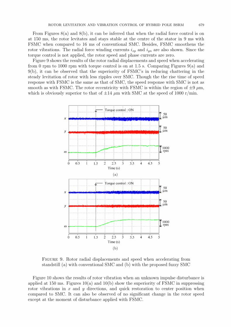
Figure 9 shows the results of the rotor radial displacements and speed when acceleratingfrom 0 rpm to 1000 rpm with torque control is on at 1.5 s. Comparing Figures 9(a) and9(b), it can be observed that the superiority of FSMC’s in reducing chattering in thesteady levitation of rotor with less ripples over SMC. Though the the rise time of speedresponse with FSMC is the same as that of SMC, the speed response with SMC is not assmooth as with FSMC. The rotor eccentricity with FSMC is within the region of ±9 µm,which is obviously superior to that of ±14 µm with SMC at the speed of 1000 r/min.
(a)
(b)
Figure 9. Rotor radial displacements and speed when accelerating fromstandstill (a) with conventional SMC and (b) with the proposed fuzzy SMC
Figure 10 shows the results of rotor vibration when an unknown impulse disturbance isapplied at 150 ms. Figures 10(a) and 10(b) show the superiority of FSMC in suppressingrotor vibrations in x and y directions, and quick restoration to center position whencompared to SMC. It can also be observed of no significant change in the rotor speedexcept at the moment of disturbance applied with FSMC.

680 P. V. S. SOBHAN, G. V. NAGESH KUMAR AND P. V. RAMANA RAO
(a)
(b)
Figure 10. Rotor radial displacements and speed under impulse distur-bance (a) with conventional SMC and (b) with the proposed fuzzy SMC
5. Conclusions. The BSRM is a multivariable and nonlinear system with unavoidableparameter variations and unmeasured disturbances. The important feature of hybridpole type design is its inherent strong decoupling between the radial force and rotationalforce, which facilitates the independent control of rotor levitation and speed. This paperpresents a control scheme combining the fuzzy logic with sliding mode control to controlnonlinear vibrations caused by the nonlinearity of the radial force and eliminates chat-tering with enhanced performance. The experimental results demonstrate that unlike theconventional SMC, the rotor can be steadily levitated from standstill and accelerates tothe desired speed with fewer vibrations with the FSMC.
REFERENCES
[1] R. Bosch, Development of a bearingless electric motor, Proc. of ICEM, Pisa, Italy, pp.373-375, 1988.[2] J. Bichsel, The bearingless electrical machine, Proc. of Int. Symp. Magn. Suspension Technol., Hamp-
ton, VA, USA, pp.561-573, 1991.[3] K. Raggl, B. Warberger, T. Nussbaumer, S. Burger and J. W. Kolar, Robust angle-sensorless control
of a PMSM bearingless pump, IEEE Trans. Industrial Electronics, vol.56, no.3, pp.2076-2085, 2009.[4] M. Ooshima and C. Takeuchi, Magnetic suspension performance of a bearingless brushless DC motor
for small liquid pumps, IEEE Trans. Industry Applications, vol.47, no.1, pp.72-78, 2011.
ROTOR LEVITATION AND VIBRATION CONTROL OF HYBRID POLE BSRM 681
[5] T. Reichert, T. Nussbaumer and J. W. Kolar, Bearingless 300-W PMSM for bioreactor mixing, IEEETrans. Industrial Electronics, vol.59, no.3, pp.1376-1388, 2012.
[6] B. Warberger, R. Kaelin, T. Nussbaumer and J. W. Kolar, 50-N.m/2500-W bearingless motor forhigh-purity pharmaceutical mixing, IEEE Trans. Industrial Electronics, vol.59, no.5, pp.2236-2247,2012.
[7] X. Sun, L. Chen and Z. Yang, Overview of bearingless permanent magnet synchronous motors, IEEETrans. Industrial Electronics, vol.60, no.12, pp.5528-5538, 2013.
[8] J. Asama, Y. Hamasaki, T. Oiwa and A. Chiba, Proposal and analysis of a novel single-drive bear-ingless motor, IEEE Trans. Industrial Electronics, vol.60, no.1, pp.129-138, 2013.
[9] S. Ayari, M. Besbes, M. Lecrivain and M. Gabsi, Effects of the airgap eccentricity on the SRMvibrations, Proc. of Int. Conf. Elect. Mach. Drives, pp.138-140, 1999.
[10] M. Takemoto, K. Shimada, A. Chiba and T. Fukao, A design and characteristics of switchedreluctance type bearingless motors, Proc. of the 4th Int. Symp. Magn. Suspension Technol.,vol.NASA/CP-1998-207654, pp.49-63, 1998.
[11] M. Takemoto, A. Chiba, H. Suzuki et al., Radial force and torque of a bearingless switched reluctancemotor operating in a region of magnetic saturation, IEEE Trans. Industry Applications, vol.40, no.1,pp.103-112, 2004.
[12] M. Takemoto, A. Chiba and T. Fukao, A new control method of bearingless switched reluctance mo-tors using square-wave currents, Proc. of the 2000 IEEE Power Engineering Society Winter Meeting,Singapore, pp.375-380, 2000.
[13] L. Chen and W. Hofmann, Analytically computing winding currents to generate torque and levitationforce of a new bearingless switched reluctance motor, Proc. of the 12th EPE-PEMC, pp.1058-1063,2006.
[14] L. Chen and W. Hofmann, Performance characteristics of one novel switched reluctance bearinglessmotor drive, Proc. of PCC, Japan, pp.608-613, 2007.
[15] C. R. Morrison, M. W. Siebert and E. J. Ho, Electromagnetic forces in a hybrid magnetic-bearingswitched-reluctance motor, IEEE Trans. Magn., vol.44, no.12, pp.4626-4638, 2008.
[16] C. R. Morrison, Bearingless switched reluctance motor, U.S. Patent 6 727 618, 2004.[17] H. Wang, Y. Wang, X. Liu and J. W. Ahn, Design of novel bearingless switched reluctance motor,
IET Elect. Power Appl., vol.6, no.2, pp.73-81, 2012.[18] H. Wang, D.-H. Lee, T.-H. Park and J.-W. Ahn, Hybrid stator pole switched reluctance motor to
improve radial force for bearingless application, Energy Convers. Manag., vol.52, no.2, pp.1371-1376,2011.
[19] J. Zhou, Z. Deng, X. Cao, C. Liu and C. Liu, Decoupling mechanism of torque and levitation-forcecontrol for 12/4 dual-winding bearingless switched reluctance motor, International Conference onElectrical Machines and Systems (ICEMS), Chiba, Japan, pp.1-6, 2016.
[20] Z. Xu, D.-H. Lee and J.-W. Ahn, Comparative analysis of bearingless switched reluctance motorswith decoupled suspending force control, IEEE Trans. Industry Applications, vol.51, no.1, pp.733-743, 2015.
[21] L. Chen and W. Hofman, Speed regulation technique of one bearingless 8/6 switched reluctance mo-tor with simpler single winding structure, IEEE Trans. Industrial Electronics, vol.59, no.6, pp.2592-2600, 2012.
[22] X. Cao, Z. Deng and G. Yang, Independent control of average torque and radial force in bearinglessswitched-reluctance motors with hybrid excitations, IEEE Trans. Power Electronics, vol.24, no.5,pp.1376-1385, 2009.
[23] X. Cao, J. Zhou, C. Liu and Z. Deng, Advanced control method for single-winding bearinglessswitched reluctance motor to reduce torque ripple and radial displacement, IEEE Trans. EnergyConversion, 2017.