ROTAX Customer Service - Al Ain Raceway instruction 125 max evo... · 2016-01-01 · ROTAX Customer...
17
Transcript of ROTAX Customer Service - Al Ain Raceway instruction 125 max evo... · 2016-01-01 · ROTAX Customer...

ROTAX Customer Service
version 10/2015 page 2 of 17
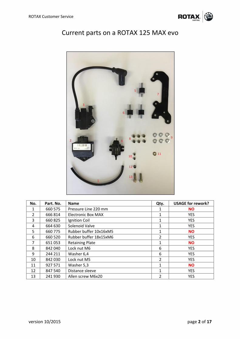
Current parts on a ROTAX 125 MAX evo
No. Part. No. Name Qty. USAGE for rework?
1 660 575 Pressure Line 220 mm 1 NO
2 666 814 Electronic Box MAX 1 YES
3 660 825 Ignition Coil 1 YES
4 664 630 Solenoid Valve 1 YES
5 660 775 Rubber buffer 10x16xM5 1 NO
6 660 520 Rubber buffer 18x15xM6 2 YES
7 651 053 Retaining Plate 1 NO
8 842 040 Lock nut M6 6 YES
9 244 211 Washer 6,4 6 YES
10 842 030 Lock nut M5 2 YES
11 927 571 Washer 5,3 1 NO
12 847 540 Distance sleeve 1 YES
13 241 930 Allen screw M6x20 2 YES

ROTAX Customer Service
version 10/2015 page 3 of 17
Bracket kit 481 257 (+ parts from a current ROTAX 125 MAX evo)
No. Part. No. Name Qty. NEW for rework?
1 660 574 Pressure Line 280 mm 1 YES (new part)
2 666 814 Electronic Box MAX 1 NO
3 660 825 Ignition Coil 1 NO
4 664 630 Solenoid Valve 1 NO
5 651 930 Retaining plate MAX 1 YES (new part)
6 660 520 Rubber buffer 18x15xM6 3 YES (quantity)
7 651 920 Mounting plate 1 YES (new part)
8 842 040 Lock nut M6 9 YES (quantity)
9 244 211 Washer 6,4 8 YES (quantity)
10 842 030 Lock nut M5 2 NO
11 827 800 Washer 5,5 2 YES (new part)
12 847 540 Distance sleeve 1 NO
14 241 930 Allen screw M6x20 2 NO
15 840 511 Allen screw M5x16 2 YES (new part)
16 651 397 Tie warp large 3 YES (new part)
17 866 714 Tie warp medium 4 YES (new part)
18 866 718 Tie wrap small 1 YES (new part)

ROTAX Customer Service
version 10/2015 page 4 of 17
STEP 1 Take one rubber buffer M6 (2) and fix it on mounting plate (1). Please note: Lock nut M6 (3) has to be fixed on the shorter threat of the rubber buffer STEP 2 Take ignition coil (1) and fix it with rubber buffer M6 (2), lock nut M6 and washer (3) on mounting plate. Please note: Lock nut M6 (3) has to be fixed on the longer threat of the rubber buffer

ROTAX Customer Service
version 10/2015 page 5 of 17
STEP 3 Take ECU (1) and fix it on the mounting plate by using a rubber buffer M6, distance sleeve, washer and lock nut M6 (2). Please note: Lock nut M6 (2) has to be fixed on the longer threat of the rubber buffer. Please note: ECU and mounting plate has the same shape in this area (3) STEP 4 Take solenoid valve (1) and fix it on the mounting plate by using two allen screws M5 and two washers (2). Please note: For models without solenoid valve use these holes (2) to fix dummy plug (666900) on this position.
ROTAX Customer Service
version 10/2015 page 6 of 17
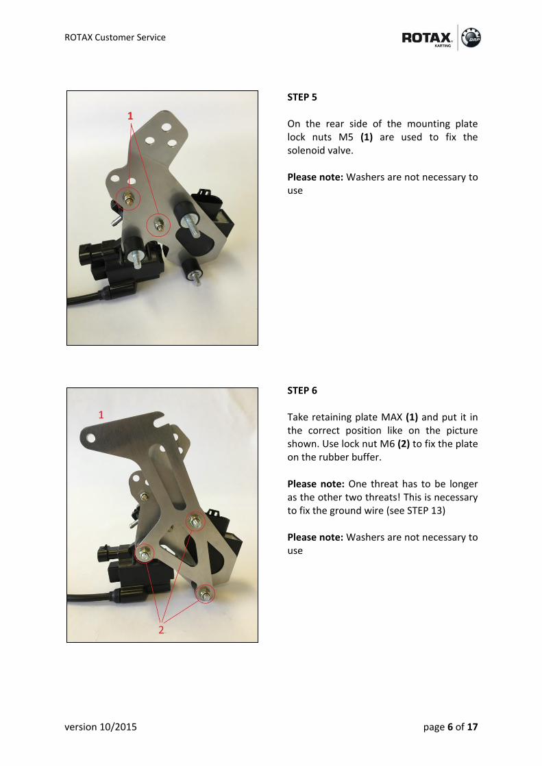
STEP 5 On the rear side of the mounting plate lock nuts M5 (1) are used to fix the solenoid valve. Please note: Washers are not necessary to use STEP 6 Take retaining plate MAX (1) and put it in the correct position like on the picture shown. Use lock nut M6 (2) to fix the plate on the rubber buffer. Please note: One threat has to be longer as the other two threats! This is necessary to fix the ground wire (see STEP 13) Please note: Washers are not necessary to use

ROTAX Customer Service
version 10/2015 page 7 of 17
STEP 7 Put pressure line 280mm (1) and fix it on the solenoid valve. Please note: Use one tie wrap to secure the hose. INFO: Hose length has been changed
NEW 660 574 pressure line 280 mm
OLD 660 575 pressure line 220 mm
STEP 8 Bring both tie wraps large in the correct position like on the picture shown (1).

ROTAX Customer Service
version 10/2015 page 8 of 17
STEP 9 Connect electric plug to the solenoid valve. Please note: Tie wrap (1) on the plug is already fixed on each wiring harness (666 831). If the wire is on the other side of the plug, please twist the wire carefully to the position like on the picture shown. Fix tie wrap (2). The cable of the solenoid valve needs to be fixed with that tie wrap only. STEP 10 Connect electric plug to ECU. Fix one tie wrap medium (1) in position like on the picture shown (approx. 20 mm distance of the plug) INFO: This step is necessary to avoid vibration on each cable strand. Bring wiring harness in position (2)

ROTAX Customer Service
version 10/2015 page 9 of 17
STEP 11 Connect electric plug to ignition coil. Use on tie wrap medium (1) to fix the wire to the ignition coil. INFO: This step is necessary to avoid vibration on each cable strand. STEP 12 Take shift contact wire and make a loop (1) Fix tie wrap (2) Tie wrap (2) is responsible to keep …
a) ECU cable b) Ignition coil cable c) Loop of shift contact cable
… in the correct position of the mounting plate
ROTAX Customer Service
version 10/2015 page 10 of 17
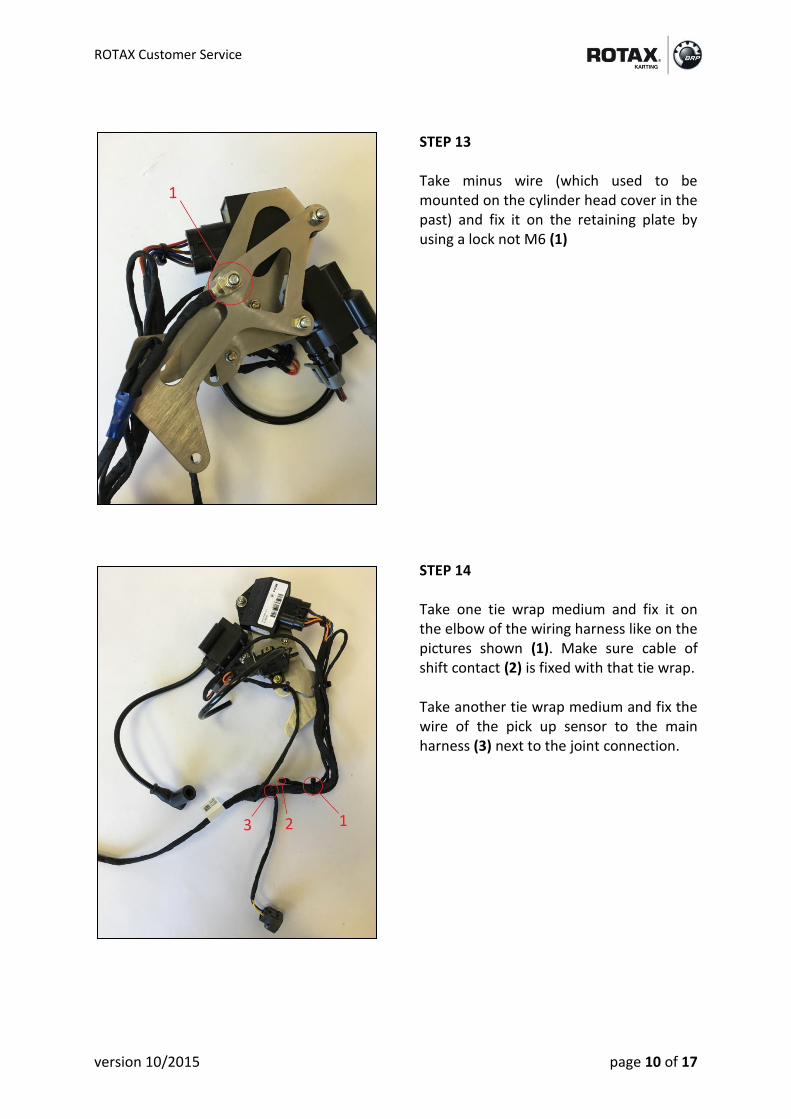
STEP 13 Take minus wire (which used to be mounted on the cylinder head cover in the past) and fix it on the retaining plate by using a lock not M6 (1) STEP 14 Take one tie wrap medium and fix it on the elbow of the wiring harness like on the pictures shown (1). Make sure cable of shift contact (2) is fixed with that tie wrap. Take another tie wrap medium and fix the wire of the pick up sensor to the main harness (3) next to the joint connection.

ROTAX Customer Service
version 10/2015 page 11 of 17
STEP 15 Remove bolt M6x20 (1) of the gear cover STEP 16 Remove the black coating in the area around the hole (2) by using a file (1) Please note: This step is required to ground/earth the engine

ROTAX Customer Service
version 10/2015 page 12 of 17
STEP 17 Tight screw M6x20 (1) by using a tightening torque of 10 Nm STEP 18 Remove the black coating on the back side of the gear cover (1) by using a file Please note: This step is required to ground/earth the engine

ROTAX Customer Service
version 10/2015 page 13 of 17
STEP 19 Take the whole bracket kit and put it on the engine. Use allen screw M6x20 (from previous retaining plate) and fix it on the gear cover (1) INFO: If you want to remove the engine, you just need to lay the bracket kit aside. It is not necessary to disassemble the whole construction. STEP 20 Make sure electrical connection between gear cover and washer is given (1) INFO: Usage of washers on this connection is nonobligatory. Just make sure, nylon part of the nut secures this connection.

ROTAX Customer Service
version 10/2015 page 14 of 17
STEP 21 Connect pick up connector to pick up sensor (1) Connect starter connector to starter motor (no picture) STEP 22 Connect spark plug connector to spark plug (1) Connect pressure line 280 mm to exhaust valve (2) Connect black pressure line (which comes from the t-fitting near fuel pump) to the metal connector of the solenoid valve (3)

ROTAX Customer Service
version 10/2015 page 15 of 17
STEP 23 Connect RED SINGLE wire on the left hand side of the relay (1) Connect RED DOUBLE wire on the right hand side of the relay (2) Connect RED SINGLE wire on the center of the relay (3) Please note: isolator on the center wire is transparent! Connect ground wire on the right hand side of the relay housing (4) STEP 24 Take one tie wrap large and fix the harness on the battery frame (1) Please note: Make sure battery charging plug is fixed with that tie wrap also (2)

ROTAX Customer Service
version 10/2015 page 16 of 17
STEP 25 Connect center connector to “CENTER” on the multifunction switch Connect ignition connector to “IGNITION” on the multifunction switch Connect start connector to “START” on the multifunction switch Please note: Labels on the wires should help you to see the correct wire Please note: If the multifunction switch isn’t mounted on the battery cover, it is much easier to connect the wires STEP 26 Connect (+) pole and (-) pole to the battery Please note: (+) pole wire is now red colored (-) pole wire is now black colored (1)

ROTAX Customer Service
version 10/2015 page 17 of 17


![fileMEGA Rübig Rotax Max Micro Rotax Max Mini Rotax Max Junior KZ 2 Masters MEGA Rübig Klasse 6 Rotax Max Senior [MRC / AKC] Klasse 3 Rotax Max DD2 / AKC] Div. V Div. IV Div. Ill](https://static.fdocuments.in/doc/165x107/5e17b05c8d318420da4b756e/rbig-rotax-max-micro-rotax-max-mini-rotax-max-junior-kz-2-masters-mega-rbig.jpg)