Rotax 912S Installation Manual - Europa Aircraft | … fit the engine mounting frame to the Rotax...
54
Europa XS Rotax 912S Installation Manual Europa XS Rotax 912S Engine Manual March 2009
Transcript of Rotax 912S Installation Manual - Europa Aircraft | … fit the engine mounting frame to the Rotax...

Europa XS
Rotax 912S Installation Manual
Europa XS Rotax 912S Engine Manual March 2009

Index of Chapters
Chapter Description
1 Engine installation
2 Engine controls
3 Oil tank
4 Exhaust system
5 Cooling duct and coolers
6 Fuel system
7 Engine cowlings
8 Cold air inlet plenum installation
9 Access doors
10 Propeller and spinner
11 Commissioning the engine
Annex A Final inspection checklist
Page i - 1 March 2009 Europa XS Rotax 912S Engine Manual

1. Engine installation
Preparation
Before starting work on the engine installation read this manual and the Rotax 912S installationmanual. There are some delicate parts attached to the engine, notably the ignition triggers, whichrequire care in handling. Instead of installing the engine mounting to the aircraft, then trying toposition a heavy engine onto it, the engine mounting should be attached to the engine first.
Engine mount fitting
There are two mounting frames associated with fitting the engine to the undercarriage frame: theengine itself is fitted to a ring mount which is a Rotax component, and that is fitted to the Europaengine mount, which in turn is fitted to the undercarriage mount.
First, if not already done so, fit the Rotax ring mount to the engine using the three M10x35 and oneM10x110 bolts. The latter bolt is fitted to the top starboard position. The bolt threads must be coatedwith Loctite 243, since wire locking is impractical.
Then fit the engine mounting frame to the Rotax ring mount using M10 x 110 bolts and M10 Binxnuts. All four bolts should be fitted with the bolt heads aft. The excess length of the bolts will need tobe cut off, leaving a minimum of two threads emerging from the end of the nut.
Engine installation
Mount the engine to the landing gear frame using the rubber mountings. See figure 1.
To check the orientation of the engine, set the fuselage level using the port door sill as the reference asusual. Check that the propeller flange is truly vertical.
The engine mounting frame has been designed with the engine offset to the right by 1.5°. To checkthat this offset is correct, clamp a straight edge to the propeller flange horizontally and mark a point51 cm (20") each side of the engine centre line. Measure the distance from these points, parallel to theaircraft centre line, to the firewall. The difference between the two readings should be 26 mm(1 1/16"). If any correction is found necessary, shim between the landing gear frame and theappropriate cup washer using AN960-516L washers. In order to ensure that the split pin is correctlypositioned relative to the castellated nut it will be necessary to use a total of at least 4 washers on eachbolt. Any washers that are not needed to act as positioning shims should be placed immediatelyunder the nut. Make a note of where and how many shim washers are used for later reference.
Note: The 4 AN5-41 mounting bolts must be tightened fully to compress the rubber anti-vibrationmounts (MT04) onto the steel spacers (MT03).
Europa XS Rotax 912S Engine Manual March 2009 Page 1 - 1

Caution: It should be noted that before the two ignition leads which come from the ignition box areearthed, the ignition is ”live”. Even though the engine speed must be at least 1200 rpm for theignition to fire, it would be a sensible precaution to fit the magneto switches before further work iscarried out on the engine, or at least temporary earth leads connecting the ignition wires to theengine casing. As it is possible to knock the ignition triggers when installing the engine mountingframe, check the trigger gaps before fitting the engine to the aircraft, as it is difficult to do soafterwards.
Propeller drive lugs
The engine is normally delivered with the six propeller drive lugs suitable for the Warp Drive groundadjustable propeller supplied loose. These are a light interference fit in the propeller flange, with arelief on the forward part to assist in starting the insertion of them into the flange.
To complete the installation it will be necessary to pull them into position using a suitable bolt, nut,and washer, with a spacer tube. Ensure that the drive lugs are fitted with no gap between the back ofthe propeller flange and the drive lug collar.
Page 1 - 2 March 2009 Europa XS Rotax 912S Engine Manual

Europa XS Rotax 912S Engine Manual March 2009 Page 1 - 3
Fig 1. Engine installation.

INTENTIONALLY BLANK
Page 1 - 4 March 2009 Europa XS Rotax 912S Engine Manual

2. Engine controls
The Rotax 912 has two independent carburettors, each one providing a fuel/air mixture to one pair ofcylinders.
The only mechanical controls required for the carburettors are throttle and choke.
Although there are two independent throttles and chokes, there is only one throttle and one chokecontrol in the cockpit.
Throttle Control
A single lever, protruding through a slot in the central spine on top of the central tunnel, provides thepilot with throttle control. The lever is mounted and pivots in a fibreglass housing fixed to theunderside of the wheel well, and operates two separate cables.
Throttle Lever Housing
Drill the holes in the throttle lever housing, as shown in figure 1.
Europa XS Rotax 912S Engine Manual March 2009 Page 2 - 1
Fig 1. Throttle lever housing drilling dimensions.

Drill also a 4.8 mm hole in each flange for mounting bolts. Open up the hole on the starboard side ofthe housing to allow a socket spanner through.
Assembly
Install the cable outers through the two holes in the housing and clamp them in position using thenyloc nut with an AN960-416L washer each side of the fibreglass. Assemble the two cables to thethrottle lever according to figure 3 ensuring the end fittings are free to pivot. Thread the cables intothe cable outers, then install the lever into the housing as shown in figure 2, adjusting the leverfriction as desired. The friction should be sufficient to prevent the carburettor throttle lever springfrom opening the throttle automatically, and this can be done after final assembly. Cover the openingin the side of the housing to keep dirt out - a suitably sized rubber grommet would be ideal.
Page 2 - 2 March 2009 Europa XS Rotax 912S Engine Manual
Fig 2. Exploded diagram of throttle lever assembly.

Installation
The throttle lever housing should be positioned such that its front face is 380 mm (15") aft of thefirewall. For the monowheel aircraft this will ensure clearance with the main wheel top when it isretracted. Mark out and cut a slot for the throttle lever in the spine in the centre tunnel then,checking that full throttle travel is achievable, drill through the flanges for mounting bolts.
For ease of installation attach an MS21047-3 anchor nut to the underside of the housing’s flange ateach end using TLPK 424 BS rivets then, using AN525-10R10 bolts, secure the housing in place.The front mounting will use an AN970-3 washer, see figure 2, and an AN970-3 washer can be usedtemporarily to hold the rear of the mounting until it is substituted by the throttle closed stop.
Make a handle from wood or any other suitable material for the top of the throttle lever to completethe installation.
Slot the throttle cables through the gap between the firewall and the upper mounting members of thelanding gear frame, securing them to the frame with tie wraps to prevent chafing. Remove anddiscard the straight cable-outer receptacle provided on each carburettor and in its place insert thethrottle cable’s threaded end. Use one check nut each side of the bracket to clamp the cable-outer inplace. The cables may seem excessively long, but this is to allow large bend radii in the engine bay toensure minimum friction.
Insert the cable inner into the nipple on the carburettor throttle lever, which is sprung to its full openposition. Setting the throttle lever in the cockpit back about 2-3 cm (1") from its full forward position,screw both nipples tight on the cables. Check for full throttle movement, making any adjustments asrequired, then seal the open hole in the throttle lever housing to prevent anything thrown up from thewheel from entering.
Throttle closed stop
The addition of a throttle-closed stop is important to avoid the possibility of excess tension on thethrottle cable causing loss of throttle control. Following the method below, prepare a plate, madefrom 3 mm (1/8”) aluminium, 50 mm (2”) wide. With the throttle closed, and the slow runningadjustment correctly set at the carburettors, measure the distance from the rear of the throttle lever,where it protrudes above the top of the tunnel, to the centre of the rear 4.8 mm (3/16”) mounting hole.The plate length will be 6 mm (1/4”) more than this measurement. Drill the plate 6 mm (1/4”) fromone end, bond with Redux to the tunnel, and bolt with an AN525-10R10 bolt.
Note: You should set the throttle closed stop such that a fully warmed engine idles at 1200 -1400 rpm. Although the engine idles more smoothly at 1600 rpm or more, when landing the aircraftyou will benefit from minimal residual thrust.
Choke Control
The two choke control cables are swaged together into the choke operating knob but run in separateouter sleeves which are swaged into a housing.
Europa XS Rotax 912S Engine Manual March 2009 Page 2 - 3

Installation
Drill a 13 mm (12“) diameter hole as low as possible in the back face of the throttle lever spine of the
cockpit moulding for the cable outer assembly to go through. See figure 3.
Push the threaded portion of the cable-outer housing through the hole and clamp it in place with thelock washer and knurled nut.
Note : As it can be difficult to insert the two cables into their respective outers, remove the plasticknob instead leaving the cables installed when mounting the outer to the cockpit module.
Decide on convenient locations for the cables to emerge from the firewall to enable easy runs to the90o angled choke cable guides mounted on the carburettors then drill 1
4“ holes right through. Push thecables through these holes, routing one to each carburettor. Push the cables into the carburettor cableguides and secure the cables to the choke levers using the solderless nipples.Ensure that the choke knob is fully in and the choke levers are fully down at the same time and thatfull choke movement can be achieved.
Squeeze silicone RTV around the cables where they come through the firewall and secure them witha cable tie to the engine mounting frame to prevent them from chafing.
To ensure that the cables don’t come out of their guides, use locking wire wrapped around the cableouter and also the cable guides.
Page 2 - 4 March 2009 Europa XS Rotax 912S Engine Manual
Fig 3.Position of choke control.

Ignition shorting cables connection
Recent Rotax engines have modified ignition shorting cable connections. The photographs in figure4 are self-explanatory.
Europa XS Rotax 912S Engine Manual March 2009 Page 2 - 5
Fig 4. Rotax ignition shorting cables connection

INTENTIONALLY BLANK
Page 2 - 6 March 2009 Europa XS Rotax 912S Engine Manual

3. Oil tank
Oil Tank Mounting Bracket
The oil tank is to be mounted to the front of the starboard footwell using a steel bracket. To make themounting bracket first mark out and cut out the steel sheet LB01 according to the drawing at the endof this chapter. Next, bend the central wide portion into a curve to match the outside of the oil tank.This can be accomplished by running the metal backwards and forwards across the corner of awooden bench whilst applying a bending force on it.
Finally, bend the lugs each side of the curved portion so that the two narrow flanges can sit flatagainst the footwell front face. See figure 1.Bending can be done by clamping the steel between lengths of wood in a vice. Try to avoid a sharpbend radius, a 10 mm (3/8") radius is ideal.
As the footwell is recessed where one of the mounting bolts would be, a separate 90 angled bracketis required to be riveted in place, which then provides support onto the top of the footwell. Make thebracket from the narrow strip shown on the template and rivet it to the top right port side usingTLPD424BS rivets -it should fit on top of the footwell.
Use TLPD424BS pop rivets to secure the angle bracket to the flange of the oil tank bracket.
Europa XS Rotax 912S Engine Manual March 2009 Page 3 - 1
Fig 1. Oil tank mounting bracket.

Bracket installation
Fasten the bracket to the tank using the two number 6X size jubilee clips. Keep the clamps awayfrom the radius of the bracket, as this may result in cracking.
With the engine and lower cowling in place position the oil tank and bracket onto the front face of thestarboard side footwell. Position the tank so that there is reasonable clearance from both the engineand cowling.
Drill through the bracket into the starboard footwell and bolt it in place using AN525-10R10 boltsand MS21042-3 nuts with AN970-3 large area washers on the inside to spread the load .
Oil tank installation
Reinstall the oil tank to its mounting bracket and orientate it so that the oil tank return fitting, which isidentified as the pipe which enters the tank at a tangent, is at the front and pointing to port.
Screw a 90° elbow union to the other tank fitting, arranging it to point to port and slightly aft. Leavethe third port plugged with its taper threaded plug.
Oil tank vent
The vent from the oil tank allows an oil mist to escape to atmosphere. It is not unusual to run the ventline to the bottom of the cowling, however if you do this, don’t position the end of the tube such that itwill be in the airstream whilst flying. This could cause low pressure at the end of the tube to suckmore oil from the tank than it should.
Another consideration is that the oil mist will tend to coat the fuselage if left to vent freely. To avoidthis you can run the vent line into a collector bottle before it goes to atmosphere, however, no bottle isprovided.
Hose connections
These are described in the chapter detailing installation of the oil cooler.
Page 3 - 2 March 2009 Europa XS Rotax 912S Engine Manual

4. Exhaust system
The exhaust system is the next item to be fitted to the engine.
Installation
Refer to figures 1 and 2 for the exhaust system and installation.
Remove and discard the blanking plugs that are located in the four exhaust ports. Fit the four downpipes to the engine, leaving the front pipes loosely bolted. Fit the silencer to the pipes by pushing theball end and socket together, and fit the springs; then tighten up the nuts holding the down pipes,ensuring that none of the pipes is strained during the fitting process.
Europa XS Rotax 912S Engine Manual March 2009 Page 4 - 1
Fig 1. Exhaust system assembly.

Page 4 - 2 March 2009 Europa XS Rotax 912S Engine Manual
Fig 2. Exhaust system installation.

5. Cooling duct and coolers
Overview
A duct is fabricated from aluminium sheet to direct cooling air to the oil cooler and radiator, whichare arranged one behind the other, with the radiator in front of the oil cooler. The duct is open at thebottom and uses the inside of the bottom cowling as the lower seal.
Duct
Figure 1 shows the assembly of the aluminium duct from the individual components.
Europa XS Rotax 912S Engine Manual March 2009 Page 5 - 1
Fig 1. Assembly of cooling duct.

Check the fit of the duct in between the footwells, and if necessary adjust the width of the duct, thenrivet the CD1, CD2 and CD3 sections together using TAPD46BS rivets.
Rivet sealing strip to the bottom sides of the duct using TAPK33BS rivets with EUR011 loadspreading washers to prevent the rivets pulling through the sealing material.
The assembled duct is fitted to the footwell using three bolts each side. The height and angle of theduct should be arranged to provide a clearance underneath the exhaust silencer of approximately5mm, and be arranged to fit the air intake opening in the lower cowling. See figure 2.
A single AN3-5A boltscrews the side of theduct onto the insideface of the footwellusing an MS21047 - 3anchor nut, installedin reverse into thefootwell to make itnearly flush; thebrackets CD4 andCD5 are then bolted tothe duct and to thefront faces of thefootwell, again usingAN3-5A bolts - theseshould have AN970-3washers to spread theload into thefibreglass structure,and MS21042-3stiffnuts.
Figure 3 illustrates the mounting of the duct and the coolers. The photographs, figures 4, 5 and 6,illustrate the duct installation.
Oil cooler
The oil cooler is mounted behind the radiator and is bolted to the duct top plate CD1 with fourAN4-5A bolts and MS21042-4 stiffnuts. Two unions are supplied- one straight and one right angled.Fit these so that the straight fitting is on the starboard side.
Note: Although not always necessary, positioning the oil cooler 5cm (2”) lower than normal willexpose its lower portion to unheated air and provide extra cooling.
Page 5 - 2 March 2009 Europa XS Rotax 912S Engine Manual
Fig 2. Approximate position of duct.

For details of the oil system connections see the Rotax Installation Manual. A schematic view is alsoshown in figure 7. One moulded hose (C06) is supplied, and a 1.5 metre length of 12 mm bore“Conti” hose is supplied with the engine.
Connect one side of the oil cooler to the 90° union fitted to the oil tank, and the other side of the oilcooler to the oil pump inlet using the pre-formed hose C06. Trim the short straight section to attachthe hose to the pump inlet so that the hose is the maximum distance from the right hand exhaust pipe.The hose runs aft and up to go over the rear cylinder water hose, under the starter motor and inside thering mount, thence it goes down to the radiator on the opposite (port) side.
Connect the oil sump drain at the bottom of the engine to the tangential fitting on the oil tank. For thisconnection use the hose marked “Conti” supplied with the Rotax engine. Set the banjo union at thebottom of the engine to point to the right and approximately 30 forwards. The hose curvesimmediately aft and up to go over the rear cylinder’s water hose, under the starter motor and insidethe engine ring mount; it then loops up to the tank.
Europa XS Rotax 912S Engine Manual March 2009 Page 5 - 3
Fig 3. Installation of duct and coolers.

Radiator
The radiator is bolted to the side plates of the cooling duct by two AN4-5A bolts and MS21042-4 nutseach side. A short hose, C05, leads from one port of the radiator to the engine coolant pump inlet, anda longer hose, C04, leads to the header tank outlet. These hoses are to be secured with 25-35 mm hoseclips.
Page 5 - 4 March 2009 Europa XS Rotax 912S Engine Manual
Fig 5. Port side view of duct (early exhaust sys-tem. shown).
Fig 4. Front view of duct showing radiator.
Fig 6. Starboard side view of duct (earlyexhaust system shown).

Europa XS Rotax 912S Engine Manual March 2009 Page 5 - 5
Fig 7. Schematic view of oil cooling system.

INTENTIONALLY BLANK
Page 5 - 6 March 2009 Europa XS Rotax 912S Engine Manual
6. Fuel system
Overview
The installation of the fuel system described in the fuselage manual takes the fuel line as far as thefuel selector valve, and assumes the use of a single fuel filter positioned after the selector valve. Thelatest fuel system uses two in-line fuel filters, positioned between the two fuel tank outlets and thefuel selector valve. Two filters are used so that, in the event of a blockage, fuel will still be availableby selecting the other side of the fuel tank. After the fuel has passed through the fuel valve the lineruns to the electric pump inlet. The electric pump is pilot activated, and is a backup to the Rotax912/912(S) engine mechanical pump. From the electric pump a line is connected to the mechanicalfuel pump inlet at the front of the engine. From the fuel pump outlet the line is taken to the carburettorinlets. A further line, incorporating a restrictor, is routed back to the starboard side of the fuel tank.This is provided to allow a small flow of fuel to prevent fuel vapourisation in hot conditions.
Installation
Electric fuel pump
The electric pump SS502 (stamped 40106 on one of the mounting flanges) is to be mounted in theport underfloor chamber situated in the baggage bay floor.
Screw the fittings HFSB 8-2N into the pump and, whilst the pump is not installed, either solderextension wires to the existing ones, or attach connectors for later use.
The pump should be positioned at approximately 45° to the horizontal with the inlet pointingdownwards and fixed to the plywood baggage bay side support. Mount the pump using two AN4-6Abolts with AN960-416 washers under the head, and MS21042-4 stiffnuts and AN970-4 washersagainst the bulkhead.
In-line filters
The in-line fuel filters are to be fitted between the tank outlets and the selector valve.
Important: Before mounting the filters into the fuel system it is necessary to incorporate a safetyspring. Without this spring it is just possible for the knurled nut, if it comes loose, to cover most ofthe fuel flow holes’ area and so limit fuel flow, and also allow unfiltered fuel to pass through,whichcould result in engine failure.
Unscrew the end fitting at the end which has the 2 fuel flow holes and the knurled nut (the inlet end).Fit the spring part number LC042G-2 over the fuel flow holes and, with it butting up against theknurled nut, refit the end fitting. Use firm hand pressure to screw on the end fitting, asover-tightening with spanners could damage or displace the O-ring seals and even break thetransparent tube.
Europa XS Rotax 912S Engine Manual March 2009 Page 6 - 1

Drill a 19 mm (3/4”) dia hole in the bottom of the seat back in front of the fuel tank outlet, and asecond hole in the side of the tunnel, just ahead of the rudder cable pulley, and high enough to avoidthe cable.
Lead the 8mm hose from the fuel tank outlet through the drilled hole, loop it back on itself andconnect it to the inlet of the filter - see figure 1. Connect the outlet of the filter to the inlet of the fuelselector valve, leaving the hosesufficiently long to enable thefilters to be lifted for removal andcleaning. Ensure that the port tankoutlet connects to the “main” sideof the fuel selector, and thestarboard side to the “reserve”side. Seal the holes around the fuelhoses with silicone to preventchafing.
Make a suitable seat base over thefilter and hoses - this seat basewould normally be arranged to belevel with the control tube tunnel.The base should be easi lyremovable for inspection. Thebase must be strong enough andsufficiently well supported suchthat, in the event of a firm landing,it will not collapse or causedamage to the filter and fuel hosesunderneath. Plywood, 3mm thickor more, supported by styrofoam,may be used in the outer bays andthe starboard inner bay..
In the port inner bay the styrofoam must be protected against degradation in case of fuel leakagewhich would dissolve the foam. After shaping the foam, layup two plies of “bid” over each piece offoam, ensuring that the whole surface is rendered impervious to fuel. See figureabove.
Drill a 6mm (1.4”) hole through the floor of the seat pan at the lowest point to allow any leaking fluidto drain away.
The outlet of the selector valve points aft; connect a length of the 8mm fuel hose to the outlet fittingHFSB 8-4N (which should already be fitted to the selector valve), and route it aft through the tunnelunder the fuel tank, into the port underfloor chamber, and connect it to the electric pump.
Page 6 - 2 March 2009 Europa XS Rotax 912S Engine Manual

Electric pump to mechanical pump
From the electric fuel pump to the engine use the same 8mm fuel hose. Thread it again under the fueltank and run it forward, underneath the brake master cylinder to emerge through the landing gearmount approximately 10 cm (4") below the top of the tunnel. Run the hose up the rear of the engineand over the top between the ignition box and the starboard carburettor to the mechanical pump. Theinlet to this pump is the larger upper tube. To protect against vapour locking, sleeve the hose forwardof the firewall with insulating firesleeve and ensure that you don’t route the hose too close tocomponents which will be very hot. Use hose clips to secure the connections.
Mechanical pump to carburettors
Connect a length of the smaller bore 6mm fuel hose to the smaller outlet fitting on the mechanicalfuel pump and route it alongside the inlet hose. Cut the hose aft of the carburettor and install a ‘T’piece HFTS 6-6-6. Connect it to the starboard carburettor with a short piece- approx 5cm (2”) of6mm hose. Connect the remaining leg of the ‘T’ with a length of the hose to another ‘T’ piece whichin turn should be fitted as close as possible to the port carburettor inlet.
Fuel return line
Connect a length of the 6mm fuel hose to the unused leg of the second ‘T’, having first pushed therestrictor FS02 a short distance into the engine end of the hose. Run this line back to the fuel tank,generally following the fuel supply line, but finishing at the starboard (reserve) fuel tank outlet.Connect a union HFSB 6-2N to the unused port of the F09C fitting, and connect the return line to thisport. If your aircraft is fitted with the optional water drain kit, then you will need to fit a T pieceHFTP 8-6-8 into the line between the tank outlet and the drain valve. The return line is then fitted tothis T piece.
Fuel sight gauge calibration
When the time comes to calibrate the fuel sight gauge, ensure that the valve is positioned to take fuelfrom the port side of the tank, which is the ‘Main’ side. Set the aircraft level to simulate level flightthen pour in sufficient fuel to fill both sides of the tank, 25 litres minimum will be required to do this.
Now empty the port side of the tank only, so that you can calibrate the gauge without the effect of thereserve side filling up causing anomalies. Next, pour in fuel in equal quantities, 5 litres at a time forexample. Mark off the gauge after each 5 litres has been added, bearing in mind that, due to the tunnelin the tank and the variations in cross-section, the marks will not be equally spaced.
Another point to consider is that, after the fuel has been used down below the top of the tunnel, thesight gauge will indicate the level of the port side of the tank (main) only.
The fuel tank is designed to hold approximately 9 litres of reserve fuel. However, this amount may bereduced in turbulent conditions. There will be a small quantity of unusable fuel.
Europa XS Rotax 912S Engine Manual March 2009 Page 6 - 3

Page 6 - 4 March 2009 Europa XS Rotax 912S Engine Manual
Fig 1. Schematic diagram of fuel system components.

Europa XS Rotax 912S Engine Manual March 2009 Page 6 - 5
Fig 2. Fuel system

INTENTIONALLY BLANK
Page 6 - 6 March 2009 Europa XS Rotax 912S Engine Manual

7. Engine cowlings
The upper and lower engine cowlings are trimmed to fit together and fit into the joggle at the front ofthe fuselage for mounting. The cowlings are held together using countersunk screws throughTinnerman washers into anchor nuts mounted to the lower cowling. Attachment of the cowlings tothe fuselage is also by means of similar screws and anchor nuts.
The trimming required will be: -
1. Removal of the flat areas, at the rear of the air outlet ramp in the lower cowling, at the two circularareas at the lower cowling front, and at the lower rectangular areas at the front of the lower cowling.When doing the first of these jobs leave a small flange, about 4 - 5mm (3/16”) around the outlet togive it some stiffness.
2. Opening the up the side cooling gills.
3. Manufacture of the NACA inlet on the top of the upper cowling (described in the next chapter).
4. Cutting the hole in the upper and lower cowlings for the propeller shaft. Initially cut a hole in thecentre of this front circular area the same size as the propeller shaft. This will enable the cowlings tolocate on the propeller shaft making subsequent fitting easier.
For the tri-gear version an extra slot must be cut in the rear of the lower cowling to allow for the nosegear leg - the size is shown in figure 1.
Europa XS Rotax 912S Engine Manual March 2009 Page 7 - 1
Fig 1. Slot for nose gear leg.

Installation
Mark a line on the upper cowling 13 mm (12“) away from and parallel to the “horizontal” edge. Mark
the centres for the holes to join the two cowlings together according to the drawing in figure 2.
Note: The joint between the cowling halves is not horizontal with the aircraft datum waterline 0.
Place the two cowlings together and hold them with clamps or adhesive tape then try them in place onthe front of the fuselage.
Trim the bottom edge of the top cowling if necessary so that both cowlings can sit snugly in placethen drill through the centres with a 3.2 mm (1
8“) drill. Use clecos through some of the holes to holdthe cowlings together.
Since the engine has already been set to the correct position relative to the fuselage, the cowlings willbe set so that the front circular flat area is concentric with the engine propeller flange.
Trim the rear edge of the cowlings as required to ensure a good fit to the fuselage, with the front faceconcentric with the propeller flange. The front face of the cowlings should be set to be 25mm (1”)behind the front face of the propeller flange.
Finally, after fitting the cowlings, cut out the front circular face of the cowlings to leave a flange 25mm (1") wide.
Page 7 - 2 March 2009 Europa XS Rotax 912S Engine Manual
Fig 2. Cowling trimming and position of attachment screws

Now mark a line, on both cowlings, 13 mm from and parallel to their rear edges. Mark the holecentres according to figure 2 and drill through with a 1/8" drill and use clecos to hold them in place.
Enlarge the holes joining the two cowlings together to 4.8 mm (3/16"), except for the rearmost holeeach side, and install MS21047-3 anchor nuts (10 in total) to the inside of the lower cowling withTAPK33BS countersink rivets.
The remaining holes should also be opened to 4.8 mm and MS21047-3 anchor nuts installed to theinside of the fuselage using countersink rivets. As the thickness of the fuselage where the anchor nutsare to be located will vary depending on their position a selection of 3.2 mm diameter countersinkrivets are provided. Use the shortest rivet that you can for attaching each anchor nut into the fuselage.
Countersink the outside face of all the holes of the upper cowling and the rearmost holes only of thelower cowling, except the upper rear holes, to allow the Tinnerman washers to lie flat against thecowling surface. The cowlings may now be fitted using the AN507C-1032R12 screws.Shorter MS24693-C272 screws may be used for joining the two cowlings together and these may belong enough to be used in some places securing the cowlings to the fuselage; however, note that thelower inboard screws need to be longer than the rest.
ROTAX 912S EXTRA AIR INLETS
Introduction
The Rotax 912S engine is provided with a glass fibre cowl around the cylinders to ensure thatsufficient cooling air reaches them. There is a tubular air inlet for this cowl which is located to thestarboard side of the propeller hub. To enable air to enter the cowl inlet, the Europa’s lower cowlingrequires an additional air inlet to be made in it. (See figure 3). Because of the relative angles of theinlet and the lower cowling, a simple hole is not adequate and so an inlet with a lip is required.
This inlet is easilymade by using apre-made “splash”moulding whichneeds to be attachedtemporarily to thelower cowling. Theinlet lip is laid uponto the “splash”moulding lappingonto the cowling.After cure the“splash” mouldingis removed leavingthe inlet attached tothe cowling.
Europa XS Rotax 912S Engine Manual March 2009 Page 7 - 3
Figure 3. Lower cowl showing completed extra inlet.

Preparation
Locate the scribed line for the inlet hole in the lower cowling which is between the main central inletand the starboard side circular inlet. This line indicates the cut-out required to allow the “splash”moulding to fit to the outside of the lower cowling.
Cut the hole in the cowling following the scribe line and trial fit the “splash” moulding to the outsideof the lower cowling, trimming the hole as required until it fits properly. A slightly oversized hole isnot a problem as this will be catered for when laying up the inlet lip.
To prevent the intake lay-up sticking to the “splash” mould, coat the smooth side of the “splash” witha release agent. Wax based polish should work ok if no proper release agent is available.
Scuff sand 2-3cm (“1”) surrounding the hole in the lower cowling on the inside only, in preparationfor the intake lay-up.
Scraps left over from larger lay-ups will be ideal to use, if you still have them, otherwise cut enoughsmall pieces to enable a three ply lay-up to make the inlet.
Finally, secure the “splash” mould in position on the outside of the cowling, holding it securely withadhesive tape.
Intake Lay-up
To give a surface which can be sanded to blend the intake lay-up into the cowling, first apply to theexposed “splash” mould only a stiffish mix of epoxy and Expancell Micro. This will act as a gel coatsimilar to the grey surface of the cowling. It is not necessary to use a proper gel coat for thisapplication.
Wipe off any significant amount of micro which may have got onto the cowling. Traces can be left aswe are not dealing with a highly stressed bond here.
Without allowing the micro to cure, lay-up pieces of “bid” cloth, lapping about 2cm (3/4”) onto thecowling and running onto the “splash” mould. Ensure that the glass fibres go properly into thecorners and cover as much of the mould as you can. Overlap adjacent pieces of “bid” by 5-6mm(1/4”) at least. A total of 3 plies thickness should be laid up to form the intake. After lay-up iscomplete, cover the lay-up edges with peel ply and leave to cure before removing the “splash”mould.
Trimming
The intake tube should be trimmed to be within about 6mm (1/4”) of the cowl inlet of the shroud onthe engine. There is no need to seal the junction between the inlet tubes, or even make them a closerfit. Remember that the engine will move relative to the cowling and contact between the inlet tubes isnot desirable.
Page 7 - 4 March 2009 Europa XS Rotax 912S Engine Manual

8. Cold air inlet plenum installation
The engine inlet air is fed through a NACA duct situated in the top cowling. It passes into a plenumchamber which feeds the air directly to the carburettors. This ensures that the coolest air available isused at all times, thus ensuring no reduction of engine performance.
Plenum chamber preparation
Drain holes
In the lowest point of each inlet tube drill a 3.3 mm (1/8") hole to allow any collected water to drainfrom the plenum. See figure 1.
Carburettor vent tubes
The 6 mm diameter plastic vent tubes on the starboard side of each carburettor must be inserted intothe plenum chamber for the engine to run properly. Position the plenum chamber with thecarburettors and, checking that the tubes will reach, mark and drill a 1/4” hole into the sloping face ofthe plenum about 4 - 5 cm (1.5” - 2”) down from the upper surface. See figure 1.
Air filter
The air filter should be a tight fit into the square hole cut into the top of the plenum chamber. Theradius under the filter flange will cause the flange to not quite reach the plenum chamber surface.This is normal.
Europa XS Rotax 912S Engine Manual March 2009 Page 8 - 1
Drain holes
Carbure ttor vent tube holes
Fig 1. View of plenum chamber (inverted) showing drain and carburettor vent tube holes.

Installation
Cut the 2"diameter rubber hose to make two 2" long pieces, then clamp the hoses to the tubes of theplenum chamber and to the two carburettors using four size 3 hose clamps.
A support, made from 20mm (3/4”) wide 3mm thick aluminium, to take the weight of the plenumchamber is attached to the engine mounting. Install the p-clip MS21919-D20 around the uppermember of the engine mounting frame (see figure 2), and attach the support to it with an AN3-3A boltand MS21042-3 nut.
Taking the weight of the plenum chamber and with the support in position behind it drill through bothparts with a 4.8 mm drill. Block off the carburettors with rags to prevent swarf entering them whilstyou do this.
Rivet an MS21047-3 anchor nut to the inside of the plenum chamber using TLPD424BS rivets. Toguard against the possibility of the tail of a rivet mandrel coming loose and falling into a carburettor,either crimp the rivet end closed or push the tail out with a small punch.
Page 8 - 2 March 2009 Europa XS Rotax 912S Engine Manual
Fig 2. Sectional view of plenum chamber assembly.
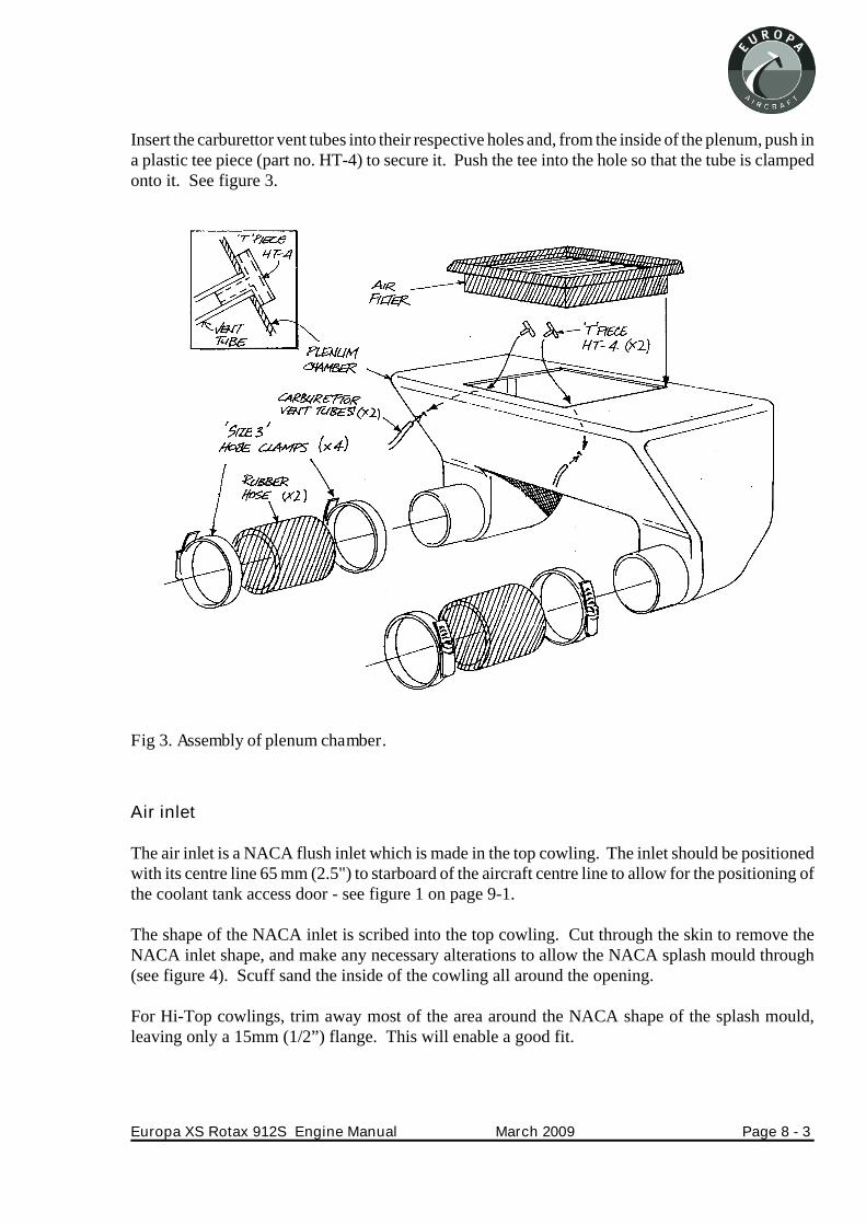
Insert the carburettor vent tubes into their respective holes and, from the inside of the plenum, push ina plastic tee piece (part no. HT-4) to secure it. Push the tee into the hole so that the tube is clampedonto it. See figure 3.
Air inlet
The air inlet is a NACA flush inlet which is made in the top cowling. The inlet should be positionedwith its centre line 65 mm (2.5") to starboard of the aircraft centre line to allow for the positioning ofthe coolant tank access door - see figure 1 on page 9-1.
The shape of the NACA inlet is scribed into the top cowling. Cut through the skin to remove theNACA inlet shape, and make any necessary alterations to allow the NACA splash mould through(see figure 4). Scuff sand the inside of the cowling all around the opening.
For Hi-Top cowlings, trim away most of the area around the NACA shape of the splash mould,leaving only a 15mm (1/2”) flange. This will enable a good fit.
Europa XS Rotax 912S Engine Manual March 2009 Page 8 - 3
Fig 3. Assembly of plenum chamber.

Having coated the splash mould with release agent, such as polished wax, attach it to the cowlingouter surface with adhesive tape.
Layup 2 plies of ‘bid’ at45° over the splash mould, lapping onto the inside of the cowling by at least2cm (3/4”). The rectangular are at the rear of the NACA inlet will be open, so there is no need for thelayup to cover it.
Skirt seal flanges
To seal the NACA inlet to the top of the plenum chamber a skirt of reinforced rubber sheeting will beused.
The skirt seals against the top surface of the plenum chamber on the periphery of the air filter. An airtight seal is not required.
A flange, made from glassfibre much like the side pieces of the inlet, is moulded to the cowlingunderside, onto which the skirt is attached with pop rivets.
The flange may be made at the same time as making the NACA side pieces. Make cardboard formersin the manner described for the side pieces, and fix them to the cowling underside so that the front andrear flanges are as shown in figure 2, and the side flanges are just outboard of the air filter edges, notthe plenum edges as the front and rear faces are. It will be necessary for the front flange to be stepped,being fitted to the underside of the cowling and the bottom of the NACA duct, flush with its outlet.
Lay-up three plies of ‘bid’ onto the cowling and duct underside, lapping onto the formers. Peel plythe edges and allow to cure.
After cure, remove the formers and peel ply, then trim the flanges to finish about 25 mm (1") abovethe top of the plenum chamber.
Page 8 - 4 March 2009 Europa XS Rotax 912S Engine Manual
Fig 4. Lay-up of NACA duct sides.

Skirt seal
Cut the length of the reinforced rubber strip so that it goes around the skirt seal flange from one sideof the inlet to the other. Drill both the flange and the rubber strip with a 3.3 mm (1/8") drill at about 3cm (1/4") intervals, and rivet the two together using TAPD46BS rivets and load spreading washersEUR011. The rivet head is best against the glassfibre so that the washer is against the rubber toprevent it pulling through.
Cut the rubber at each corner as required to allow the skirt to spread on contact with the plenumchamber. Gaps here are not critical; the air above the filter is normally at a higher pressure than itssurroundings so that warm air will not enter the plenum chamber. The skirt should not fit too tightlyonto the chamber to avoid any transmission of vibration from the engine.
Europa XS Rotax 912S Engine Manual March 2009 Page 8 - 5
Fig 5. Assembly of NACA duct and plenum chamber.

INTENTIONALLY BLANK
Page 8 - 6 March 2009 Europa XS Rotax 912S Engine Manual

9. Access doors
To enable access to check oil and coolant before flight, two hinged doors are required in the topcowling. See figure 1. The hinge line of the coolant access door lies 2.5cm (1”) to port of the aircraftcentre line, and the oil tank access door is centred over the oil tank.
The doors themselves are cut from the cowling, so mark out 12 cm (434“) squares centred over both
the water expansion tank (not to be confused with the optional overflow bottle) and the oil tank.Carefully cut the door panel from the cowling with a knife or thin hacksaw blade to minimise the gaparound it.
Flange
Reposition the door panels in the openings as accurately as possible and tape them temporarily inplace from the outside.
Scuff sand the inside of the cowling around the door panels. Cover the door panel with plasticsheeting to act as a release agent.
Europa XS Rotax 912S Engine Manual March 2009 Page 9 - 1
Fig 1. Approximate position of access doors and NACA inlet.
Lay up four plies of ‘bid’ at +/- 45o around the door panels lapping onto the cowling approximately2-3 cm (1").
Cover the lay-ups with peel-ply and allow to cure before removing the door panels.
Trim the flange to be 18mm (3/4”) wide. Drill through this flange, on the side opposite to where thehinge will be, centred 7mm from the flange edge, with an 8mm drill. Now drill through the accessdoor to match the above hole, with a 6mm (1/4”) drill.
Fit the spring receptacle 82-47-113-20 to the flange. Fit the white wear washer 82-46-101-39 to the¼ turn fastener 82-11-200-20, insert the fastener through the door, and fit the retainer 82-32-301-12.
Hinges
Cut a piece of 20001-3 hinge to be 75 mm (3") long for each door and file a clearance cut-out for thehinge pivot in both the door panel and cowling. Bond and rivet the hinge in place using countersunkTLPK424BS rivets. Countersink the cowling and door panel with a drill before riveting.
Page 9 - 2 March 2009 Europa XS Rotax 912S Engine Manual

10. Propeller and spinner
This chapter relates to the fitting of the Warp Drive ground adjustable propeller. If other groundadjustable propellers are fitted the general principles will apply, but details will vary. Refer to thefigure showing the propeller and spinner arrangement at the end of this chapter.
Spinner bulkheads
Rear bulkhead
Carefully mark out and drill with a hole saw six holes in the rear bulkhead, concentric with theperiphery, to allow through the propeller drive lugs which are installed in the engine propeller flange.Cut out also the central hole required for the boss in the propeller flange. Make these holes such thatthe bulkhead is not loose on the lugs and centre boss.
Front bulkhead
Mark out and drill six holes in the front bulkhead, concentric with the periphery, to allow through thepropeller attachment bolts.
Also make holes in the front bulkhead, centred on where each of the propeller blade clamping boltswill be, to allow a suitably sized socket through with some clearance.
Drill through the head of each propeller attachment bolt to allow locking wire to be used.
Propeller
Assemble the propeller according to the manufacturer’s instructions, setting the blade angles onlyapproximately at this stage. Fine setting of blade angle is best done on the aircraft. Tighten the boltsaccording to the manufacturers specification.
File the front bulkhead flange locally to clear each propeller blade, then bolt the propeller to theengine propeller flange with the bulkheads either side of the propeller hub, and the face plate againstthe front bulkhead. Tighten these bolts according to the manufacturer’s specification. Mark bothbulkheads and the propeller flange to note their relative positions for later reference.
Spinner
Cut away sufficient of the rear edge of the spinner in the three positions where the propeller bladesare to allow the spinner’s rear edge to align with the rear bulkhead flange. Allow a clearance of about3-4mm (1/8") around the blades.
Although it’s a good starting point, don’t rely on the alignment of the flanges of the spinner and rearbulkhead to ensure the spinner is true.
Europa XS Rotax 912S Engine Manual March 2009 Page 10 - 1

Hold the spinner in place using adhesive tape or clamps then, with some form of reference pointerpositioned close to the spinner about 10 - 15cm (4"-6") back from the front, carefully (with ignitionoff - note that if the ignition leads have not yet been wired to switches the ignition will be live!)rotate the propeller by hand to check for concentricity. Removal of a spark plug from each cylinderwill make turning the propeller easier.
Adjust the spinner as required to achieve concentricity then mark out and drill nine 4.8mm holes,three equally spaced between each blade, through the spinner and the rear bulkhead flange.
Remove the spinner and install MS21047-3 anchor nuts onto the inside of the rear bulkhead’s flangeusing TAPK 33 BS countersink rivets.
Measure accurately the distance from the rear bulkhead’s rear flange to the radial centre line for thefront bulkhead screws.
Mark a line around the spinner for the front screw radial centre line then mark off six equally spacedcentres around the circumference.
Drill through both the spinner and the front bulkhead flange with a 4.8mm drill at the six centres, theninstall MS21047-3 anchor nuts to the bulkhead using TAPK 33 BS rivets.
The spinner is now ready for installation with screws; however, the propeller pitch must be setbeforehand.
Propeller pitch
The relationship between propeller pitch and aircraft performance is something which will varyslightly between aircraft, so a certain amount of experimentation will be required to establishindividual aircraft performance figures.
Also, individual requirements, such as runway length available, will influence the final propellersetting used.
For the Rotax 912 engine, with the Warp Drive 62” diameter propeller with tapered blades, it issuggested that you set the propeller to 17° pitch angle initially, measured at the tip. For the Rotax912S engine, with the Warp Drive 64” diameter propeller with non-tapered blades, set the pitchinitially to 19º. Whichever fixed pitch or ground adjustable propeller is fitted, when the aircraft isstationary and the engine is at wide open throttle (WOT) you should see a minimum of 5200rpm.Theblade angle referred to is the angle between the propeller’s rotational plane and the flat rear surface ofthe blade at the propeller tip. Ensure that all blades are within 1/4° of each other.
Page 10 - 2 March 2009 Europa XS Rotax 912S Engine Manual
Make any subsequent pitch adjustments of no more than 1o at a time, assessing the difference inflight performance each time.
Blade pitch adjustment
You may find your own method for adjusting the propeller blade pitch but the following method hasbeen found to work well.
Measure the angle to the vertical that the propeller flange is at by using the inclinometer, which isprovided with the Warp Drive propeller, and make a note of it.
The vernier scale enables accurate measurement of angles to within 5 minutes of arc. A descriptionof how to use it is included later.
Next rotate the inclinometer 17° from the propeller flange angle (clockwise when viewing from theport side of the aircraft.
Adjusting method
Set the propeller blade that is to be adjusted horizontal, with the leading edge uppermost, checkingthis with a spirit level.
Clamp the inclinometer to the back of the blade tip.
Slacken off the four blade clamping bolts and the four closest propeller hub securing bolts. It shouldnow be possible to rotate the blade to the desired angle.
Once the blade angle is set, tighten the bolts, 20 inch pounds at a time, starting with the bolts nearestthe centre and working outwards. After tightening the bolts, check that the blade angle setting has notaltered.
Turn the propeller to the next blade and repeat the sequence.
After the last blade has been set, check that the others have not been disturbed. Don’t accept amismatch between blades of an angle any more than 15 minutes of arc. Having satisfied yourself thatthe blades are within acceptable limits, wirelock the six propeller securing bolts in pairs. See the insetdiagram in the main figure.
Run the engine to check that the desired static R.P.M. is achieved then install the spinner, checking itfor concentricity.
Warning : It is imperative that special care is taken in the attachment of the spinner. If it is notsecurely fastened and departs the aircraft in flight it will destroy the propeller which could result infailure of the engine mounting.
Europa XS Rotax 912S Engine Manual March 2009 Page 10 - 3

Note: The Warp Drive propeller may be supplied with some leading edge protection tape. Ourexperience has shown that its inclusion degrades propeller performance, and its use is notrecommended.
Balance
To avoid damage to engine parts, instruments, etc., it may be necessary to balance thepropeller/spinner assembly. Dynamic balancing is recommended.
The vernier scale
The vernier scale on the inclinometer supplied with the Warp Drive propeller is designed to allow theaccurate measurement of small angles that would otherwise be too small to see using a standardscale.
The principle of its operation is the alignment of lines on inner and outer scales. The outer scale onyour inclinometer is in degrees of arc and the inner scale represents minutes of arc.
As an exercise, using the inclinometer, align the two zeros of inner and outer scales together.
If you now look at the alignment of the graduations of both inner and outer scales you will see thatthey progressively misalign as you move away from the zero and then, after the 30 of the inner scale,they start to realign until the graduation marked 60 is back in line with a graduation on the outer scale.See the first illustration in the figure below.
Page 10 - 4 March 2009 Europa XS Rotax 912S Engine Manual
Fig 1. Vernier scales

Europa XS Rotax 912S Engine Manual March 2009 Page 10 - 5
Fig 2. Propeller and spinner assembly

If you now look at the graduation mark representing 15 on the inner scale and rotate this scale to alignwith the nearest adjacent graduation on the outer scale you will have moved the inner scale 15minutes of arc or 1/4o. See the second illustration in the figure below.
Looking at how the two zeros have misaligned will confirm that the inner scale has movedsomething like 1/4o but, without the vernier it would be difficult to be absolutely sure.
INTENTIONALLY BLANK
Page 10 - 6 March 2009 Europa XS Rotax 912S Engine Manual

11. Commissioning the engine (912/912S)
Overview
There are several checks that need to be made as part of commissioning the engine. You need to besure that there are no restrictions in the oil lines or the fuel lines, and that the engine oil system is fullyprimed before first start up. You also need to check that both the electric and the mechanical fuelpumps provide sufficient pressure at the carburettors.
Note: Refer to the Europa Final Inspection Checklist for the Rotax 912/912S at Annex A beforecommencing commissioning.
A limited amount of test equipment is necessary for commissioning, and kits are available fromEuropa Aircraft on hire to carry it out.
Fuel Flow Checking
Checking the fuel flow of the electric fuel pump is carried out with the engine stationary.
Connecting the test kit
Disconnect the fuel line at the last carburettor in the circuit, after the fuel return line, and insert the ‘T’piece and control valve from the test kit. Arrange a suitable receiver for the discharge from thecontrol valve, which will need to be able to measure a quantity of approximately 2 litres.
Setting up
With the aircraft fuel selector valve on Main, switch on the electric pump. Open the stop valve andadjust the setting of the control valve such that the pressure on the gauge is 0.15bar (2.2psi). Closethe stop valve.
Checking Flow
Now empty the receiver, then open the stop valve and measure the time taken to deliver 2 litres offuel.
The JAR-VLA requirement is for a flow rate of 125% of full power fuel consumption. To achievethis the pump must deliver the 2 litres in not more than 4 minutes (912), or 2.25 litres in 4 minutes(912S).
After this test is completed close the stop valve, and leave the test equipment in position ready for themechanical fuel pump test which will follow later.
Europa XS Rotax 912S Engine Manual March 2009 Page 11 - 1

Oil system
It is necessary to check that the suction at the oil pump inlet is not excessive. Rotax specify amaximum depression of 0.3 bar (4.4 psi) below ambient pressure at the oil pump inlet at full throttle.To check this a ‘T’ piece must be inserted into the oil pump suction line.
Disconnect the hose from the oil pump inlet, and connect the short hose and ‘T’ piece from the testkit, with the pressure/vacuum gauge connected to the leg of the ‘T’.
This test has to be carried out with the engine running at full throttle, and will be carried out later.
Before first start it is necessary to prime the oil system.
There are 2 methods to achieve this - which one you use depends on whether or not you have acompressed air line:-
Method 1
1. Block the return line from the bottom of the engine to the oil tank, by disconnecting it at thetank, and plugging the tank connection.
2. Using a compressed air line with a pressure between 2 and 3 bar (30 to 45 psi) pressurise theoil tank through its vent connection. This pressure is to be maintained for at least 30 seconds; itwill help if during this time you get an assistant to turn the propeller in the normal direction.
Note: Ensure that the ignition is off, and for ease of turning, remove one spark plug from eachcylinder.
3. Unblock the return line, refit the vent line to the tank, and refit the spark plugs if removed.Spin the engine with the starter with the ignition still off and check the pressure reading. Itshould rise immediately, but if it has not risen within 10 seconds, stop and repeat the primingprocedure. Continue cranking until a stable pressure of at least 1.5 bar (22 psi) is reached.
Method 2
1. Carry out step 1 above.
2. Disconnect the suction line at the oil pump inlet connection. Pressurise the oil tank using abicycle pump or other low pressure source into the vent connection on the neck of the tank.Continue with the pressure until oil flows freely from the hose which you disconnected from theoil pump. Quickly reconnect the hose and remove pressure. Rotate the engine several times withthe propeller as described above.
3. Carry out step 3 above.
Page 11 - 2 March 2009 Europa XS Rotax 912S Engine Manual

After priming, make sure that all oil connections are secure and that the oil tank is still full at least toits mid level.
First start
Although the engine has been run in by the manufacturers, it is prudent to operate it initially at a fairlyconservative power setting until you are sure that there are no problems with cooling.
Once you are happy with the general engine running you can carry out the remaining fuel and oilsystem checks.
Oil system
Run the engine at full power, and check that the depression in the oil inlet pipe as measured by thegauge already fitted is less than 0.3 bar (4.4 psi).
Checking Mechanical Pump
Having already checked the electric fuel pump, you must now check the mechanical pump.
With the test kit still in the fuel line close the control valve and open the stop valve. Run the engine atfull power and adjust the control valve until the pressure is 0.15 bar (2.2 psi). Again measure the fuelflow into the receiver; this time the flow rate must be a minimum of 25% of the fuel consumption atfull power, which equates to 1 litre in 10 minutes.
Repeat this test with the fuel selector valve at Reserve.
Finally check that, with the engine idling and both fuel pumps operating, the fuel pressure does notexceed 0.3 bar (4.4 psi).
CAUTION
When conducting any checks do not run the engine at high power settings without having suitablysecured the aircraft against unwanted movement. For monowheel aircraft it is strongly advised totie the tailwheel down to prevent the possibility of nosing over.
Europa XS Rotax 912S Engine Manual March 2009 Page 11 - 3

INTENTIONALLY BLANK
Page 11 - 4 March 2009 Europa XS Rotax 912S Engine Manual

Annex A - Final Inspection Checklist
A/C Reg...................................................L.A.A No (UK only)..................................................
Owner........................................Kit Serial no........................................Date............................
Engine type: Rotax 912/912S Engine serial no..................................
Propeller make and Designation ................................. Diameter.................
Check the Europa website for the latest version of this checklist.
Note: This check list only covers specific items for inspection of the Europa aircraft. Generalinspection must be carried out in addition to these items. Items covered in the inspection stagesduring construction are not included in this list.
The inspector should check and initial each separate iem of these inspection sheets. Duplicate checkitems require a second signature. For aircraft registered with the L.A.A. a copy must be sent to theEngineering Department of the L.A.A.
The latest mandatory Europa modification which affects the engine installation is Mod 72.
Check that the engine complies with all Rotax mandatory bulletins and Europa mandatorymodifications issued to date. The engine may be “new” but a bulletin or two may have been issuedsince the engine was built (or since purchase).
General
Check incorporation of Mod 72 - Undercarriage Mounting Frame Reinforcement
Check clearance between the engine mounting frame and the moving parts (CS21) of the rudder andcable installation.
Verify that the coolant mixture is 50/50 glycol/water, in accordance with the Rotax OperatorsHandbook and Service Bulletin SB3UL97R1.
Mounting bolts
Check that four washers are present on each bolt, whether used between the engine mount andlanding gear frame to adjust engine orientation, or as spacing washers. Check that the nuts are splitpinned.
Europa XS Rotax 912S Engine Manual March 2009 Page 12 - 5

Lubrication system
Mod 48 - routing of oil hose
Check that the oil outlet banjo bolt (underside) is wire locked.
Check that the drain plug (port front) is wire locked.
Carburettors
Check incorporation of Mod 32 - Engine bay fuel line insulation
Check that the carburettors are secured with spring support (Rotax part) or wire locked to balancepipe elbow fitting.
Check that rubber mounting flange clamp has 7 mm gap, and that the gap is on the underside.
Duplicate check that both throttles are working over the full range, and that they close together.
Check that the choke control works correctly and closes fully.
Check that fuel inlet banjos are correctly orientated.
Check that overflow pipes terminate near air inlet filters or inside plenum chamber.
Electrics
Check for chafing of wires through firewall.
Check that metal p-clip is used without insulation to clamp the metal braided sheath around thecables from the ignition boxes.
Check that an earth wire is connected to the above p-clip.
Propeller and spinner
Check ground adjustable propeller bades pitch angles are within 1/4° of each other.
Check for correct wire locking.
Check that tracking of blades is within 3mm (1/8”).
Check that spinner runs true.
Page 12 - 6 March 2009 Europa XS Rotax 912S Engine Manual

Operation
Check maximum static rpm is 5200 or higher (fixed pitch and ground adjustable propllers) - seechapter 10 page 2.
Check and record fuel flow with both electric and mechanical fuel pumps - see chapter 11.
Mogas (Aircraft on U.K. register)
Rotax engines are designed to run on Mogas. Please note that if you intend to use Mogas in youraircraft it is necessary to apply for permission from the L.A.A.
Europa XS Rotax 912S Engine Manual March 2009 Page 12 - 7

INTENTIONALLY BLANK
Page 12 - 8 March 2009 Europa XS Rotax 912S Engine Manual