Rotational Speed Pin Profile Microstruture Tensile Strength Dissimilar AA5083 AA6351
10
Technical Report Effect of tool rotational speed and pin profile on microstructure and tensile strength of dissimilar friction stir welded AA5083-H111 and AA6351-T6 aluminum alloys R. Palanivel a,⇑ , P. Koshy Mathews b , N. Murugan c , I. Dinaharan d a Department of Mechanical Engineering, Kalaivani College of Technology, Coimbatore 641 105, Tamil Nadu, India b Research and Development, Kalaivani College of Technology, Coimbatore 641 105, Tamil Nadu, India c Department of Mechanical Engineering, Coimbatore Institute of Technology, Coimbatore 641 014, Tamil Nadu, India d School of Mechanical Sciences, Karunya University, Coimbatore 641 114, Tamil Nadu, India article info Article history: Received 14 January 2012 Accepted 16 March 2012 Available online 23 March 2012 abstract The relatively new welding process friction stir welding (FSW) was applied in this research work to join 6 mm thick dissimilar aluminum alloys AA5083-H111 and AA6351-T6. The effect of tool rotational speed and pin profile on the microstructure and tensile strength of the joints were studied. Dissimilar joints were made using three different tool rotational speeds of 600 rpm, 950 rpm and 1300 rpm and five dif- ferent tool pin profiles of straight square (SS), straight hexagon (SH), straight octagon (SO), tapered square (TS), and tapered octagon (TO). Three different regions namely unmixed region, mechanically mixed region and mixed flow region were observed in the weld zone. The tool rotational speed and pin profile considerably influenced the microstructure and tensile strength of the joints. The joint which was fabricated using tool rotational speed of 950 rpm and straight square pin profile yielded highest ten- sile strength of 273 MPa. The two process parameters affected the joint strength due to variations in material flow behavior, loss of cold work in the HAZ of AA5083 side, dissolution and over aging of pre- cipitates of AA6351 side and formation of macroscopic defects in the weld zone. Ó 2012 Elsevier Ltd. All rights reserved. 1. Introduction Many specific properties of aluminum alloys including light weight and good structural strength enable them to be applied for structural parts. The demand of aircraft and automotive indus- tries for light weight materials is met by aluminum alloys. The alu- minum alloys AA6XXX and AA5XXX are extensively used in the fabrication of aircraft structures and other structural applications [1]. Dissimilar welding of these two alloys is frequently faced in those structures. Structural parts and frames composed of these aluminum alloys can be welded using sound welding techniques commonly used in industries. But conventional fusion welding of aluminum alloys results in numerous welding defects which in- cludes voids, hot cracking, distortion, precipitates dissolution, loss of work hardening and lack of penetration in the joints [2,3]. There- fore, solid state bonding technique is highly recommended to solve those problems. Friction stir welding (FSW) is an appropriate solid state welding technique to effectively join any combination of dissimilar alumi- num alloys [4]. FSW was invented at The Welding Institute (TWI), UK in 1991. A nonconsumable rotating tool harder than the base material is plunged into the abutting edges of the plates to be joined under sufficient axial force and advanced along the line of the joint. The tool consists of two parts namely shoulder and pin. The material around the tool pin is softened by the fric- tional heat generated by the tool rotation. Advancement of the tool pushes plastically deformed material from front to back of the tool and forges to complete the joining process [5]. Since FSW is a solid state process, a solidification structure is absent in the weld. There- fore, all the defects related to the presence of brittle inter dendritic and eutectic phases are eliminated [6]. The major FSW process parameters which influence the joint strength and microstructure are tool rotational speed, welding speed, axial force and tool tilt an- gle [7]. The dimensions and shape of the tool play a crucial role to obtain sound joints. The tool design significantly alters material flow and consolidation of plasticized material during welding [8]. Some studies on FSW of dissimilar AA5XXX and AA6XXX joints were reported in the literatures [9–19]. Shigematsu et al. [9] at- tempted to join 3 mm thick dissimilar AA5083 and AA6061 alloys using FSW and examined the microstructure and the mechanical 0261-3069/$ - see front matter Ó 2012 Elsevier Ltd. All rights reserved. http://dx.doi.org/10.1016/j.matdes.2012.03.027 ⇑ Corresponding author. Mobile: +91 9943707552; fax: +91 422 2575020. E-mail addresses: [email protected], [email protected] (R. Palanivel), [email protected], [email protected] (P. Koshy Mathews), [email protected], [email protected] (N. Murugan), [email protected], [email protected] (I. Dinaharan). Materials and Design 40 (2012) 7–16 Contents lists available at SciVerse ScienceDirect Materials and Design journal homepage: www.elsevier.com/locate/matdes
-
Upload
daniel-marques -
Category
Documents
-
view
33 -
download
0
Transcript of Rotational Speed Pin Profile Microstruture Tensile Strength Dissimilar AA5083 AA6351
Materials and Design 40 (2012) 7–16
Contents lists available at SciVerse ScienceDirect
Materials and Design
journal homepage: www.elsevier .com/locate /matdes
Technical Report
Effect of tool rotational speed and pin profile on microstructureand tensile strength of dissimilar friction stir welded AA5083-H111and AA6351-T6 aluminum alloys
R. Palanivel a,⇑, P. Koshy Mathews b, N. Murugan c, I. Dinaharan d
a Department of Mechanical Engineering, Kalaivani College of Technology, Coimbatore 641 105, Tamil Nadu, Indiab Research and Development, Kalaivani College of Technology, Coimbatore 641 105, Tamil Nadu, Indiac Department of Mechanical Engineering, Coimbatore Institute of Technology, Coimbatore 641 014, Tamil Nadu, Indiad School of Mechanical Sciences, Karunya University, Coimbatore 641 114, Tamil Nadu, India
a r t i c l e i n f o
Article history:Received 14 January 2012Accepted 16 March 2012Available online 23 March 2012
0261-3069/$ - see front matter � 2012 Elsevier Ltd. Ahttp://dx.doi.org/10.1016/j.matdes.2012.03.027
⇑ Corresponding author. Mobile: +91 9943707552;E-mail addresses: [email protected]
(R. Palanivel), [email protected],(P. Koshy Mathews), [email protected], [email protected], [email protected]
a b s t r a c t
The relatively new welding process friction stir welding (FSW) was applied in this research work to join6 mm thick dissimilar aluminum alloys AA5083-H111 and AA6351-T6. The effect of tool rotational speedand pin profile on the microstructure and tensile strength of the joints were studied. Dissimilar jointswere made using three different tool rotational speeds of 600 rpm, 950 rpm and 1300 rpm and five dif-ferent tool pin profiles of straight square (SS), straight hexagon (SH), straight octagon (SO), taperedsquare (TS), and tapered octagon (TO). Three different regions namely unmixed region, mechanicallymixed region and mixed flow region were observed in the weld zone. The tool rotational speed andpin profile considerably influenced the microstructure and tensile strength of the joints. The joint whichwas fabricated using tool rotational speed of 950 rpm and straight square pin profile yielded highest ten-sile strength of 273 MPa. The two process parameters affected the joint strength due to variations inmaterial flow behavior, loss of cold work in the HAZ of AA5083 side, dissolution and over aging of pre-cipitates of AA6351 side and formation of macroscopic defects in the weld zone.
� 2012 Elsevier Ltd. All rights reserved.
1. Introduction
Many specific properties of aluminum alloys including lightweight and good structural strength enable them to be appliedfor structural parts. The demand of aircraft and automotive indus-tries for light weight materials is met by aluminum alloys. The alu-minum alloys AA6XXX and AA5XXX are extensively used in thefabrication of aircraft structures and other structural applications[1]. Dissimilar welding of these two alloys is frequently faced inthose structures. Structural parts and frames composed of thesealuminum alloys can be welded using sound welding techniquescommonly used in industries. But conventional fusion welding ofaluminum alloys results in numerous welding defects which in-cludes voids, hot cracking, distortion, precipitates dissolution, lossof work hardening and lack of penetration in the joints [2,3]. There-fore, solid state bonding technique is highly recommended to solvethose problems.
ll rights reserved.
fax: +91 422 2575020., [email protected]
[email protected]@cit.edu.in (N. Murugan),du (I. Dinaharan).
Friction stir welding (FSW) is an appropriate solid state weldingtechnique to effectively join any combination of dissimilar alumi-num alloys [4]. FSW was invented at The Welding Institute(TWI), UK in 1991. A nonconsumable rotating tool harder thanthe base material is plunged into the abutting edges of the platesto be joined under sufficient axial force and advanced along theline of the joint. The tool consists of two parts namely shoulderand pin. The material around the tool pin is softened by the fric-tional heat generated by the tool rotation. Advancement of the toolpushes plastically deformed material from front to back of the tooland forges to complete the joining process [5]. Since FSW is a solidstate process, a solidification structure is absent in the weld. There-fore, all the defects related to the presence of brittle inter dendriticand eutectic phases are eliminated [6]. The major FSW processparameters which influence the joint strength and microstructureare tool rotational speed, welding speed, axial force and tool tilt an-gle [7]. The dimensions and shape of the tool play a crucial role toobtain sound joints. The tool design significantly alters materialflow and consolidation of plasticized material during welding [8].
Some studies on FSW of dissimilar AA5XXX and AA6XXX jointswere reported in the literatures [9–19]. Shigematsu et al. [9] at-tempted to join 3 mm thick dissimilar AA5083 and AA6061 alloysusing FSW and examined the microstructure and the mechanical

Table 1Chemical composition of AA6351-T6 and AA5083-H111.
Aluminum alloy Si Zn Mg Mn Fe Cu Ti Al
AA6351-T6 0.907 0.89 0.586 0.65 0.355 0.086 0.015 BalanceAA5083-H111 0.045 0.04 4.76 0.56 0.14 0.02 0.054 Balance
Table 3Welding parameters.
Process parameters Values
Tool rotational speed (rpm) 600, 950 and 1300Welding speed (mm/s) 60Axial force (kN) 8Tool tilt angle (�) 0Tool shoulder diameter (mm) 18Tool shoulder surface FlatPin diameter (mm) 6Pin length (mm) 5.7Pin profile* SS, SH, SO, TS and TOTool material High carbon high chromium steelTool hardness (HRC) 63
* SS – straight square; SH – straight hexagon; SO – straight octagon; TS – taperedsquare and TO – tapered octagon.
Fig. 1. Fabricated FSW tools.
8 R. Palanivel et al. / Materials and Design 40 (2012) 7–16
properties of the joint. Peel et al. [10] investigated the processingwindow of 3 mm thick AA5083 and AA6082 joints and found thatthe tool rotational speed strongly influenced the heat generationduring welding than the traverse speed. Peel et al. [11] studiedthe effect of tool rotational speed and traverse speed on the micro-structure, hardness and precipitate distribution of 3 mm thickAA5083 and AA6082 joints. Steuwer et al. [12] quantified the effectof tool rotational speed and traverse speed on the residual stress of3 mm thick AA5083 and AA6082 joints. He concluded that the toolrotational speed was a useful process variable to optimize theresidual stress. Leal et al. [13] elaborated the influence of toolshoulder geometry on material flow in 1 mm thick AA5182-H111and AA6016-T4 joints. A tool shoulder with a conical cavity was re-ported to yield an onion ring structure. Leitao et al. [14] analyzedthe tensile behavior of 1 mm thick AA5182-H111 and AA6016-T4joints and observed that the grain size in the TMAZ and precipitatedistribution influenced the tensile behavior. Leitao et al. [15] as-sessed the formability of 1 mm thick AA5182-H111 and AA6016-T4 joints by deep drawing cylindrical cups and noticed that themismatch in mechanical properties between the weld and the basematerials determined the formability limits. Park et al. [16] inves-tigated the effect of material locations on the properties of 2 mmthick AA5052-H32 and AA6061-T6 joints and observed a propermixing of dissimilar aluminum alloys when AA5052-H32 was keptin the advancing side. Aval et al. [17] estimated the effect of toolgeometry on 5 mm thick AA5086-O and AA6061-T6 joints. He usedthree tool geometries and found that the tool with a concaveshoulder and a conical probe with three grooves provided morehomogeneous stir zones compared to other tools due to higherheat input. Aval et al. [18] used finite element software to predictthe thermo-mechanical behaviors of 5 mm thick AA5086-O andAA6061-T6 joints and compared the simulation results with theobserved microstructures. Aval et al. [19] evaluated the thermomechanical behavior and microstructural events of 5 mm thickAA5086-O and AA6061-T6 joints and observed that the tempera-ture field was distributed asymmetrically resulting in larger ther-mally affected region in the AA6061 side.
In this work, an attempt is made to join 6 mm thick aluminumalloys AA5083-H111 and AA6351-T6 using FSW and investigatethe influence of tool rotational speed and pin profile on the micro-structure and tensile strength of the dissimilar joints.
2. Experimental procedure
Aluminum alloys AA6351-T6 and AA5083-H111 which havethe chemical compositions and mechanical properties listed inTables 1 and 2, respectively were used in this research work. Platesof size 100 mm X 50 mm X 6 mm were prepared from the rolledplates. AA6351-T6 and AA5086-H111 were respectively kept inthe advancing side and retreating side of the joint line. The FSWline was parallel to the rolling direction of AA5083-H111 and per-
Table 2Mechanical properties of AA6351-T6 and AA5083-H111.
Base material UTS (MPa) Yield strength (MPa) Percentage elongation
AA6351-T6 310 285 14AA5083-H111 308 273 23
pendicular to the rolling direction of AA6351-T6. This joint choicewas made to induce the most severe mechanical combination [20].The welding parameters and fabricated tools are presented in Table3 and Fig. 1, respectively. The dissimilar butt welding was carriedout automatically in an indigenously built FSW machine (M/s RVMachine Tools, Coimbatore, INDIA).
Specimens were cut from the welded plates perpendicularto FSW line to carry out microstructural characterization. Thespecimens were prepared as per standard metallographic proce-dure and etched with modified Keller reagent followed by Wecksreagent. The digital image of the macrostructure of the etchedspecimens was captured using a digital optical scanner.
The microstructure was observed using an optical microscope(OLYMPUS-BX51M). The tensile specimens were prepared as perASTM E8 standard having a gauge length of 40 mm, a gauge widthof 7 mm and a thickness of 6 mm [21]. Three such tensile speci-mens were prepared from each joint and the average value ofultimate tensile strength (UTS) was taken. The UTS was estimatedusing a computerized universal testing machine (HITECHTUE-C-1000).
3. Results and discussions
FSW of 6 mm thick aluminum alloys AA5083-H111 andAA6351-T6 was accomplished. The two aluminum alloys have dif-ferent flow stress. Aluminum alloy AA5083 offers more resistanceto plastic flow compared to AA6351 [22]. Certain combinations oftool rotational speed and pin profile yielded sound welds. Thecrown appearance of dissimilar welds using different pin profiles

Fig. 2. Crown appearances of dissimilar welds obtained at tool rotational speed of 950 rpm using tool pin profiles: (a) SS; (b) SH; (c) SO; (d) TS and (e) TO.
Fig. 3. Macrostructure of the welded dissimilar joints.
R. Palanivel et al. / Materials and Design 40 (2012) 7–16 9
at tool rotational speed of 950 rpm is shown in Fig. 2. Semicircularfeatures which are identical to those produced during conventionalmilling process are seen on the crown. The formation of those fea-tures is due to rubbing of FSW tool shoulder on the plates to bejoined. Ceschini et al. [23] described the formation of such featuresinduced by FSW as wake effect. The crown presents smoothappearance without the presence of voids, cracks, depressionsand excessive flashes. The tool shoulder design helps to obtainsuch a crown appearance. The tool shoulder design adopted in thisstudy is identical for all tool pin profiles. The tool shoulder asshown in Fig. 1 has flat surface and three concentric grooves ofdepth 1 mm and width 2 mm. This tool design is an optimized de-sign to conventional conical shoulder and complete flat shoulder.The flat surface and three concentric grooves serve the same func-tions of conical shoulder which is easy to manufacture similar to acomplete flat shoulder. The cavity in a concave shoulder is requiredfor the following causes; (i) to form a compressed annular ring ofwork piece material around the tool pin; (ii) to prevent the escapeof plasticized material and (iii) to direct the material flow towardsthe pin [24]. In the present work, the three concentric groovesperform the same role of the cavity in a concave shoulder and pro-duce sound joints.
3.1. Macrostructure and microstructure of dissimilar joints
The macrostructure of all the fifteen dissimilar joints arerevealed in Fig. 3. It is evident from the figure that the joints fabri-cated at all tool rotational speeds using tool pin profiles SS, SH and
10 R. Palanivel et al. / Materials and Design 40 (2012) 7–16
SO are defect free. A tunnel at the bottom of the joint is alwayspresent when tapered tool pin profiles are used at all tool rota-tional speeds. A sound joint forms when proper combinations ofthose factors are met with. The two process parameters, tool rota-tional speed and pin profile which are considered in this presentwork contributes remarkably to the generation of frictional heatduring welding [25]. The rubbing of tool shoulder on the workpiece develops frictional heat. As tool rotational speed increasesthe frictional heat also increases due to increased residing timeof tool. The macrostructures suggests that sufficient frictional heatis formed to plasticize both the aluminum alloys at all tool rota-tional speeds using straight pin profiles which yielded defect freewelds. A straight pin profile tool has more contact area comparedto tapered tool. The transportation of plasticized material fromadvancing side to retreating side is uniform from top to bottomof the joint when straight pin profile tool is employed. The interac-tion between tool and plasticized material is less in tapered pin
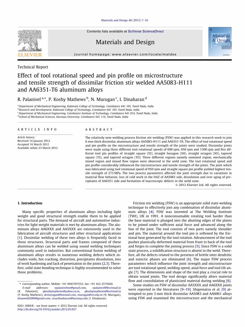
Fig. 4. Microstructure of various regions in the weld zone as marked in the macrostructuand (e) mechanically mixed region.
profile tool owing to lesser contact area. The material swept acrossthe depth of the joint is nonuniform and affects regular materialflow characteristics. As a result, the shoulder experience lesser gripon the plasticized material and sliding condition is promoted oversticking condition. Therefore as the weld proceeds, a drop in fric-tional heat is experienced. Because, sliding condition generates les-ser heat than that of sticking condition [8]. Inadequate sweeping ofplasticized material and reduction in frictional heat leave a tunnelat the bottom of the joint.
The microstructure of the weld zone obtained using differenttool pin profiles at tool rotational speed of 950 rpm is presentedin Figs. 4–8. It is evident from these figures that the microstructureof the dissimilar joint is dependent to a large extent on the positionwithin the weld zone. Different microstructures are observed whilemoving across the breadth and depth of the weld zone. All theobserved microstructures can be categorized into three differentregions namely unmixed region, mechanically mixed region and
re using SS tool pin profile at 950 rpm: (a) unmixed region; (b–d) mixed flow region
R. Palanivel et al. / Materials and Design 40 (2012) 7–16 11
mixed flow region. The mixed flow region is absent in the jointsfabricated using tapered pin profiles. The same region is also notpresent in the joints fabricated using straight pin profiles at toolrotational speed of 650 rpm. The formation of three kinds of re-gions within the weld zone agrees to the reporting of some inves-tigators in dissimilar friction stir welded aluminum alloys[26,9,17].
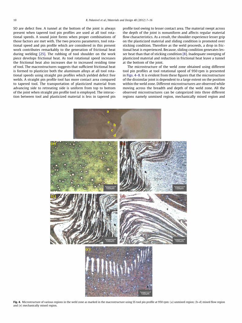
The formation and characterization of the three regions are de-tailed as follows. To begin with, the unmixed region (Figs. 4a, 5a,6a, 7a and 8a) contains the microstructure of either AA5083 orAA6351. This region is observed at the top of the joints closerto shoulder region. The fine grain structure indicates that thisunmixed region experienced dynamic recrystallization duringwelding. Secondly, the mechanically mixed region (Figs. 4e, 5e,6e, 7b and c and 8b and c) contains the microstructure of boththe aluminum alloys. The etchant reveals AA5083 as darker andAA6351 lighter in color. The plasticized dissimilar alloys are
Fig. 5. Microstructure of various regions in the weld zone as marked in the macrostructuand (e) mechanically mixed region.
mechanically coupled to each other. The penetration of one alu-minum alloy into the other is not fully accomplished. But dy-namic recrystallization of grains is evident. Finally, the mixedflow region (Figs. 4b–d, 5b–d, 6b–d) contains a structure of alter-native lamellae of both the aluminum alloys. A complex vortexlike flow pattern is visible. The mixed flow region presents ex-treme super plastic flow of plasticized material which createschaotic intercalation patterns. The stirring action of the toolcauses intense plastic deformation and in situ extrusion of alumi-num alloys AA6351 and AA5083. The plasticized material is trans-ported layer by layer which forms such a lamellae structure. Thepenetration and mixing of both the aluminum alloys in this re-gion is intense.
The structure of mixed flow region obtained using SS tool pinprofile differs slightly with those obtained using SH and SO toolpin profiles. Almost equal number of alternative lamellae ofAA5083 and AA6351 alloys is visible using SH and SO tool pin
re using SH tool pin profile at 950 rpm: (a) unmixed region; (b–d) mixed flow region

Fig. 6. Microstructure of various regions in the weld zone as marked in the macrostructure using SO tool pin profile at 950 rpm: (a) unmixed region; (b–d) mixed flow regionand (e) mechanically mixed region.
12 R. Palanivel et al. / Materials and Design 40 (2012) 7–16
profiles. All the straight tools employed in the present work haveflat surfaces. The geometry of the tool pin profile is uneven com-pared to a round or threaded tool which influences the plasticizedmaterial flow behavior. A flat tool creates a pulsating stirring ac-tion due to the associated eccentricity [27]. The pulsating stirringaction offers resistance to the regular flow of plasticized materialwhich generates additional frictional heat. Consequently, thematerial is more plasticized. SS, SH and SO tool pin profiles pro-duce 63, 95 and 127 pulses/s, respectively at tool rotational speedof 950 rpm. The intensity and duration of the pulse are inverselyproportional to the number of flat faces in a straight tool. There-fore, SS tool pin profile produces high intense and long durationof pulse compared to other straight tool pin profiles which resultsin severe and random layer by layer transfer of material (Fig. 3b–d). The pulsating action of SO tool is weak because the tool pin pro-file approaches closer to cylindrical shape. On the other hand, the
tapered pin profile tools are ineffective to produce pulsating stir-ring action and layer by layer transfer of plasticized material.Hence, the mixed flow region is not present.
The formation of mixed flow region is further observed to bedependent on tool rotational speed. The mixed flow region is ab-sent at tool rotational speed of 600 rpm (The microstructure of un-mixed and mechanically mixed regions is similar to those regionsobserved at tool rotational speed of 950 rpm. Hence, no separatemicrostructure is presented). Alvarez et al. [28] also noticed the ab-sence of mixed flow region at tool rotational speed of 400 rpm indissimilar friction stir welded AA7075–AA2024. It is mentionedearlier that the tool rotational speed determines the generationof frictional heat and amount of plasticized material. The volumeof plasticized material and interaction of tool is lower at toolrotational speed of 600 rpm. Hence, the mixed flow region is notformed.
Fig. 7. Microstructure of various regions in the weld zone as marked in the macrostructure using TS tool pin profile at 950 rpm: (a) unmixed region; (b) and (c) mechanicallymixed region.
R. Palanivel et al. / Materials and Design 40 (2012) 7–16 13
3.2. Tensile properties of dissimilar joints
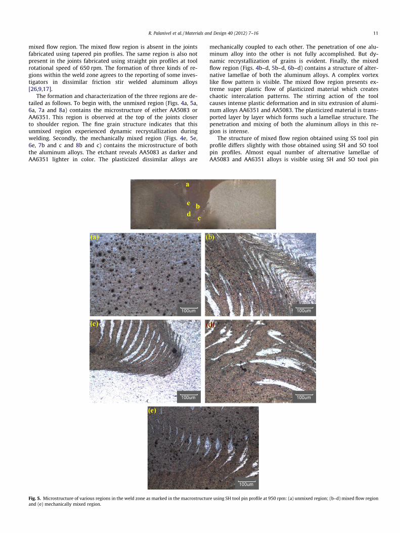
The effect of tool rotational speed and tool pin profile on thetensile strength of the dissimilar joints is depicted in Fig. 9. It isevident from the figure that the joints fabricated using tool rota-tional speed of 950 rpm exhibit highest tensile strength for all toolpin profiles. Among the five tool pin profiles studied, joints fabri-cated using SS pin profile yielded highest tensile strength. The frac-ture location of some of the dissimilar joints is shown in Fig. 10.The dissimilar joint failed in any one of the following locations:(i) weld zone, (ii) HAZ of AA5083 side and (iii) near TMAZ ofAA6351 side.
The factors which determine the tensile strength of dissimilaraluminum alloy joints are: (i) presence of macroscopic defects inweld zone, (ii) degree of plastic flow and amount of mixing of boththe materials, (iii) grain size in HAZ, (iv) degree of dissolution andover aging of precipitates. The joints fabricated using tapered pinprofiles yielded poor tensile strength due to macroscopic defectspresent in the weld zone at all tool rotational speeds. The jointsfabricated using straight pin profiles at tool rotational speed of950 rpm yielded highest tensile strength due to intense plasticflow and mixing of dissimilar alloys which results in smooth hard-ness variation across the joint. The tensile strength of joints fabri-cated at tool rotational speed of 600 rpm using straight pinprofiles is lower due to softening of HAZ of AA5083 side. At highertool rotational speed of 1300 rpm, dissolution and over aging ofprecipitates occur which reduce the tensile strength. A dissimilarweld can be considered as a good quality weld if failure takesplace in the weaker of the two dissimilar materials away from
the weld zone [29]. All the fifteen joints failed to satisfy this idealcondition. The macroscopic defects caused the joints to fail in theweld zone. Failure in the HAZ of AA5083 side can be attributed toloss of cold work in the HAZ due to annealing effect. Dissolutionand over aging of precipitates led the joint to fail near TMAZ ofAA6351 side.
The fracture surfaces of tensile tested dissimilar weld speci-mens using different pin profiles at tool rotational speed of950 rpm is shown in Fig. 11. All the fracture surfaces are coveredwith a large population of microscopic voids which vary in sizeand shape. Some flat zones are visible in the fracture surfaces ofdissimilar welds fabricated using tapered tools. The failure of thedissimilar joint is dictated by the coalescence of those microscopicvoids in all cases. The observed failure mode is ductile fibrous frac-ture. The depth of microscopic voids using tapered tools is lowercompared to those using straight tools which can be attributedto the early coalescence of prematurely grown micro voids.
4. Conclusions
In the present work, the influence of tool rotational speed andpin profile on the microstructure and tensile strength of the dis-similar friction stir welded aluminum alloys AA5083-H111 andAA6351-T6 were investigated. The joints fabricated using straighttool profiles had no defects while tapered tool profiles caused atunnel defect at the bottom of the joints under the experimentalconditions considered. Three different regions namely unmixedregion, mechanically mixed region and mixed flow region were
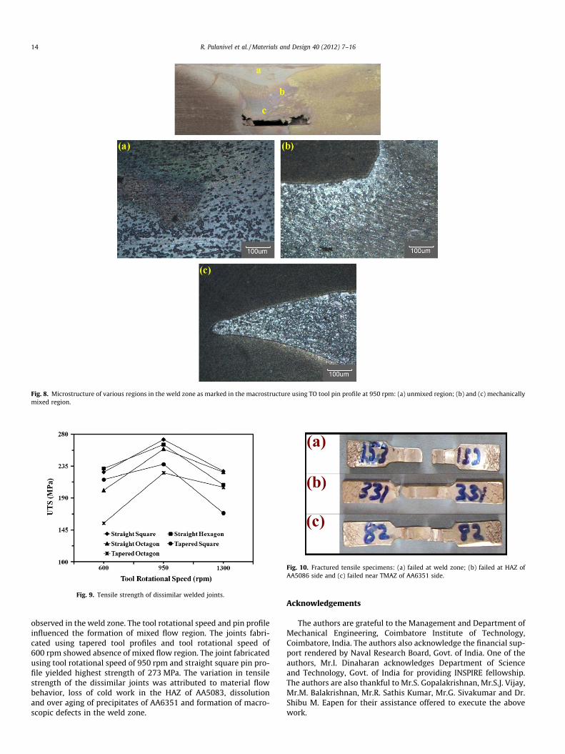
Fig. 9. Tensile strength of dissimilar welded joints.
Fig. 10. Fractured tensile specimens: (a) failed at weld zone; (b) failed at HAZ ofAA5086 side and (c) failed near TMAZ of AA6351 side.
Fig. 8. Microstructure of various regions in the weld zone as marked in the macrostructure using TO tool pin profile at 950 rpm: (a) unmixed region; (b) and (c) mechanicallymixed region.
14 R. Palanivel et al. / Materials and Design 40 (2012) 7–16
observed in the weld zone. The tool rotational speed and pin profileinfluenced the formation of mixed flow region. The joints fabri-cated using tapered tool profiles and tool rotational speed of600 rpm showed absence of mixed flow region. The joint fabricatedusing tool rotational speed of 950 rpm and straight square pin pro-file yielded highest strength of 273 MPa. The variation in tensilestrength of the dissimilar joints was attributed to material flowbehavior, loss of cold work in the HAZ of AA5083, dissolutionand over aging of precipitates of AA6351 and formation of macro-scopic defects in the weld zone.
Acknowledgements
The authors are grateful to the Management and Department ofMechanical Engineering, Coimbatore Institute of Technology,Coimbatore, India. The authors also acknowledge the financial sup-port rendered by Naval Research Board, Govt. of India. One of theauthors, Mr.I. Dinaharan acknowledges Department of Scienceand Technology, Govt. of India for providing INSPIRE fellowship.The authors are also thankful to Mr.S. Gopalakrishnan, Mr.S.J. Vijay,Mr.M. Balakrishnan, Mr.R. Sathis Kumar, Mr.G. Sivakumar and Dr.Shibu M. Eapen for their assistance offered to execute the abovework.

Fig. 11. Fracture surfaces of dissimilar welds obtained at tool rotational speed 950 rpm using tool pin profiles: (a) SS; (b) SH; (c) SO; (d) TS and (e) TO.
R. Palanivel et al. / Materials and Design 40 (2012) 7–16 15
References
[1] Heinz A, Haszler A, Keidel C, Moldenhauer S, Benedictus R, Miller WS. Recentdevelopment in aluminum alloys for aerospace applications. Mater Sci Eng A2000;280:102–7.
[2] Lee WB, Yeon YM, Jung SB. The mechanical properties related to the dominantmicrostructure in the weld zone of dissimilar formed Al alloy joints by frictionstir welding. J Mater Sci 2003;38:4183–91.
[3] Luijendijk T. Welding of dissimilar aluminum alloys. J Mater Process Technol2000;103:29–35.
[4] Murr LE. A review of FSW research on dissimilar metal and alloy systems. JMater Eng Perform 2010;19:1071–89.
[5] Mishra RS, Ma ZY. Friction stir welding and processing. Mater Sci Eng R2005;50:1–78.
[6] Threadgill PL, Leonard AJ, Shercliff HR. J. friction stir welding of aluminumalloys. Int Mater Rev 2009;54:49–93.
[7] Nandan R, Debroy T, Bhadeshia HKDH. Recent advances in friction stir welding– process, weldment structure and properties. Prog Mater Sci2008;53:980–1023.
[8] Rai R, De A, Bhadeshia HKDH, DebRoy T. Review: friction stir welding tools. SciTechnol Weld Joi 2011;16:323–42.
[9] Shigematsu I, Kwon YJ, Suzuki K, Imai T, Saito N. Joining of 5083 and 6061aluminum alloys by friction stir welding. J Mater Sci Lett 2003;22:353–6.
[10] Peel MJ, Steuwer A, Withers PJ. Dissimilar friction stir welds in AA5083-AA6082. Part II: process parameter effects on microstructure. Metall MaterTrans A 2006;37:2195–206.
[11] Peel MJ, Steuwer A, Withers PJ, Dickerson T, Shi Q, Shercliff H. Dissimilarfriction stir welds in AA5083–AA6082. Part I: process parameter effects onthermal history and weld properties. Metall Mater Trans A 2006;37:2183–93.
[12] Steuwer A, Peel MJ, Withers PJ. Dissimilar friction stir welds in AA5083–AA6082: the effect of process parameters on residual stress. Mater Sci Eng A2006;441:187–96.
[13] Leal RM, Leitao C, Loureiro A, Rodrigues DM, Vilaca P. Material flow inheterogeneous friction stir welding of thin aluminum sheets: effect ofshoulder geometry. Mater Sci Eng A 2008;498:384–91.
[14] Leitao C, Leal RM, Rodrigues DM, Loureiro A, Vilaca P. Mechanical behaviour ofsimilar and dissimilar AA5182-H111 and AA6016-T4 thin friction stir welds.Mater Des 2009;30:101–8.
[15] Leitao C, Emílio B, Chaparro BM, Rodrigues DM. Formability of similar anddissimilar friction stir welded AA5182-H111 and AA6016-T4 tailored blanks.Mater Des 2009;30:3235–42.
[16] Park SK, Hong ST, Park JH, Park KY, Kwon YJ, Son HJ. Effect of material locationson properties of friction stir welding joints of dissimilar aluminum alloys. SciTechnol Weld Joi 2010;15:331–6.
[17] Aval HJ, Serajzadeh S, Kokabi AH, Loureiro A. Effect of tool geometry onmechanical and microstructural behaviours in dissimilar friction stir weldingof AA5086–AA6061 Sci Technol Weld Joining 2011;16:597–604.
[18] Aval HJ, Serajzadeh S, Kokabi AH. Evolution of microstructures and mechanicalproperties in similar and dissimilar friction stir welding of AA5086 andAA6061. Mater Sci Eng A 2011;528:8071–83.
[19] Aval HJ, Serajzadeh S, Kokabi AH. Thermo-mechanical and microstructuralissues in dissimilar friction stir welding of AA5086–AA6061. J Mater Sci2011;46:3258–68.
[20] Cavaliere P, Nobile R, Panella FW, Squillace A. Mechanical and microstructuralbehaviour of 2024–7075 aluminum alloy sheets joined by friction stir welding.Int J Mach Tools Manuf 2006;46:588–94.
[21] ASTM Standard E8. Standard test method for tension testing of metallicmaterials. West Conshohocken (USA): ASTM, International; 2004.
[22] Leitão C, Louro R, Rodrigues DM. Analysis of high temperature plasticbehaviour and its relation with weldability in friction stir welding foraluminum alloys AA5083-H111 and AA6082-T6. Mater Des 2012;37:402–9.
[23] Ceschini L, Boromei I, Minak G, Morri A, Tarterini F. Effect of friction stirwelding on microstructure, tensile and fatigue properties of the AA7005/10vol.%Al2O3p composite. Compos Sci Technol 2007;67:605–15.

16 R. Palanivel et al. / Materials and Design 40 (2012) 7–16
[24] Scialpi A, De Filippis LAC, Cavaliere P. Influence of shoulder geometry onmicrostructure and mechanical properties of friction stir welded 6082aluminum alloy. Mater Des 2007;28:1124–9.
[25] Simar A, Bréchet Y, De Meester B, Denquin A, Gallais C, Pardoen T. Integratedmodeling of friction stir welding of 6xxx series Al alloys: process,microstructure and properties. Prog Mater Sci 2012;57:95–183.
[26] Ouyang JH, Kovacevic R. Material flow and microstructure in the friction stirbutt welds of the same and dissimilar aluminum alloys. J Mater Eng Perform2002;11:51–63.
[27] Elangovan K, Balasubramanian V. Influences of tool pin profile and weldingspeed on the formation of friction stir processing zone in AA2219 aluminumalloy. J Mater Process Technol 2008;200:163–75.
[28] Alvarez P, Janeiro G, Da Silva AAM, Aldanondo E, Echeverria A. Material flowand mixing patterns during dissimilar FSW. Sci Technol Weld Joi2010;15:648–53.
[29] Dilip JJS, Koilraj M, Sundareswaran V, Ram GDJ, Rao SRK. Microstructuralcharacterization of dissimilar friction stir welds between AA2219 and AA5083.Trans Indian Inst Met 2010;63:757–64.