Rotation and Gyroscopic Precession - Lab...
16
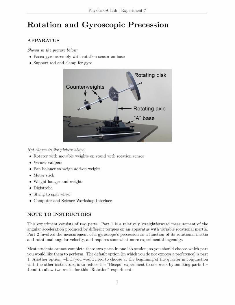
Physics 6A Lab | Experiment 7 Rotation and Gyroscopic Precession APPARATUS Shown in the picture below: • Pasco gyro assembly with rotation sensor on base • Support rod and clamp for gyro Not shown in the picture above: • Rotator with movable weights on stand with rotation sensor • Vernier calipers • Pan balance to weigh add-on weight • Meter stick • Weight hanger and weights • Digistrobe • String to spin wheel • Computer and Science Workshop Interface NOTE TO INSTRUCTORS This experiment consists of two parts. Part 1 is a relatively straightforward measurement of the angular acceleration produced by different torques on an apparatus with variable rotational inertia. Part 2 involves the measurement of a gyroscope’s precession as a function of its rotational inertia and rotational angular velocity, and requires somewhat more experimental ingenuity. Most students cannot complete these two parts in one lab session, so you should choose which part you would like them to perform. The default option (in which you do not express a preference) is part 1. Another option, which you would need to choose at the beginning of the quarter in conjunction with the other instructors, is to reduce the “Biceps” experiment to one week by omitting parts 1 – 4 and to allow two weeks for this “Rotation” experiment. 1
Transcript of Rotation and Gyroscopic Precession - Lab...
Physics 6A Lab | Experiment 7
Rotation and Gyroscopic Precession
APPARATUS
Shown in the picture below:
• Pasco gyro assembly with rotation sensor on base
• Support rod and clamp for gyro
Not shown in the picture above:
• Rotator with movable weights on stand with rotation sensor
• Vernier calipers
• Pan balance to weigh add-on weight
• Meter stick
• Weight hanger and weights
• Digistrobe
• String to spin wheel
• Computer and Science Workshop Interface
NOTE TO INSTRUCTORS
This experiment consists of two parts. Part 1 is a relatively straightforward measurement of theangular acceleration produced by different torques on an apparatus with variable rotational inertia.Part 2 involves the measurement of a gyroscope’s precession as a function of its rotational inertiaand rotational angular velocity, and requires somewhat more experimental ingenuity.
Most students cannot complete these two parts in one lab session, so you should choose which partyou would like them to perform. The default option (in which you do not express a preference) is part1. Another option, which you would need to choose at the beginning of the quarter in conjunctionwith the other instructors, is to reduce the “Biceps” experiment to one week by omitting parts 1 –4 and to allow two weeks for this “Rotation” experiment.
1
Physics 6A Lab | Experiment 7
TORQUE AND ROTATIONAL INERTIA
We are all aware that a massive wheel has rotational inertia. In other words, it is hard to startthe wheel rotating; and, once moving, the wheel tends to continue rotating and is hard to stop.These effects are independent of friction; it is hard to start a wheel rotating even if its bearings arenearly frictionless. Rotational inertia is a measure of this resistance to rotational acceleration, justas inertia is a measure of resistance to linear acceleration.
Automobile piston engines use a flywheel for this very purpose. The gasoline explosions in thepiston chambers deliver jerk-like forces to the rotating crankshaft, but the large rotational inertiaof the flywheel on the crankshaft smooths out the otherwise jerky rotational motion.
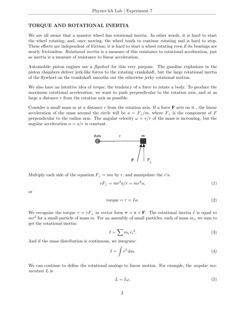
We also have an intuitive idea of torque, the tendency of a force to rotate a body. To produce themaximum rotational acceleration, we want to push perpendicular to the rotation axis, and at aslarge a distance r from the rotation axis as possible.
Consider a small mass m at a distance r from the rotation axis. If a force F acts on it , the linearacceleration of the mass around the circle will be a = F⊥/m, where F⊥ is the component of Fperpendicular to the radius arm. The angular velocity ω = v/r of the mass is increasing, but theangular acceleration α = a/r is constant.
Multiply each side of the equation F⊥ = ma by r, and manipulate the r’s:
rF⊥ = mr2a/r = mr2α, (1)
or
torque = τ = Iα. (2)
We recognize the torque τ = rF⊥ in vector form τ = r × F. The rotational inertia I is equal tomr2 for a small particle of mass m. For an assembly of small particles, each of mass mi, we sum toget the rotational inertia:
I =∑
mi ri2. (3)
And if the mass distribution is continuous, we integrate:
I =
∫r2 dm. (4)
We can continue to define the rotational analogs to linear motion. For example, the angular mo-mentum L is
L = Iω, (5)
2
Physics 6A Lab | Experiment 7
in analogy to
p = mv, (6)
and the rotational kinetic energy is
rotational KE = (1/2)Iω2, (7)
in analogy to
translational KE = (1/2)mv2. (8)
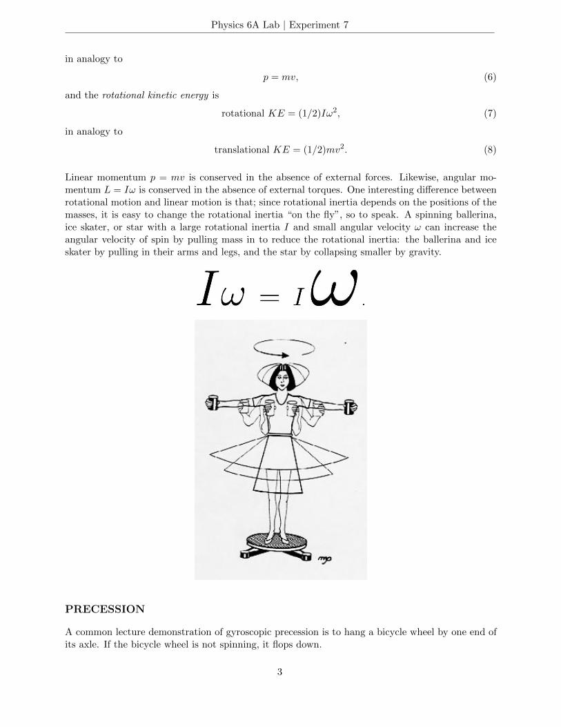
Linear momentum p = mv is conserved in the absence of external forces. Likewise, angular mo-mentum L = Iω is conserved in the absence of external torques. One interesting difference betweenrotational motion and linear motion is that; since rotational inertia depends on the positions of themasses, it is easy to change the rotational inertia “on the fly”, so to speak. A spinning ballerina,ice skater, or star with a large rotational inertia I and small angular velocity ω can increase theangular velocity of spin by pulling mass in to reduce the rotational inertia: the ballerina and iceskater by pulling in their arms and legs, and the star by collapsing smaller by gravity.
PRECESSION
A common lecture demonstration of gyroscopic precession is to hang a bicycle wheel by one end ofits axle. If the bicycle wheel is not spinning, it flops down.
3

Physics 6A Lab | Experiment 7
But if the wheel is spinning, it doesn’t fall. Instead it precesses around: its axle rotates in ahorizontal plane.
We are all familiar with the example of a precessing toy top. The spinning Earth also precessesaround. Its axis is now pointing toward the North Star in the sky, but over time the axis slowlyswings around, making a complete revolution in 26,000 years.
4
Physics 6A Lab | Experiment 7
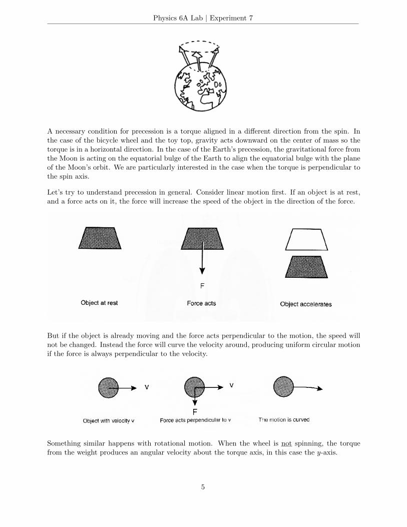
A necessary condition for precession is a torque aligned in a different direction from the spin. Inthe case of the bicycle wheel and the toy top, gravity acts downward on the center of mass so thetorque is in a horizontal direction. In the case of the Earth’s precession, the gravitational force fromthe Moon is acting on the equatorial bulge of the Earth to align the equatorial bulge with the planeof the Moon’s orbit. We are particularly interested in the case when the torque is perpendicular tothe spin axis.
Let’s try to understand precession in general. Consider linear motion first. If an object is at rest,and a force acts on it, the force will increase the speed of the object in the direction of the force.
But if the object is already moving and the force acts perpendicular to the motion, the speed willnot be changed. Instead the force will curve the velocity around, producing uniform circular motionif the force is always perpendicular to the velocity.
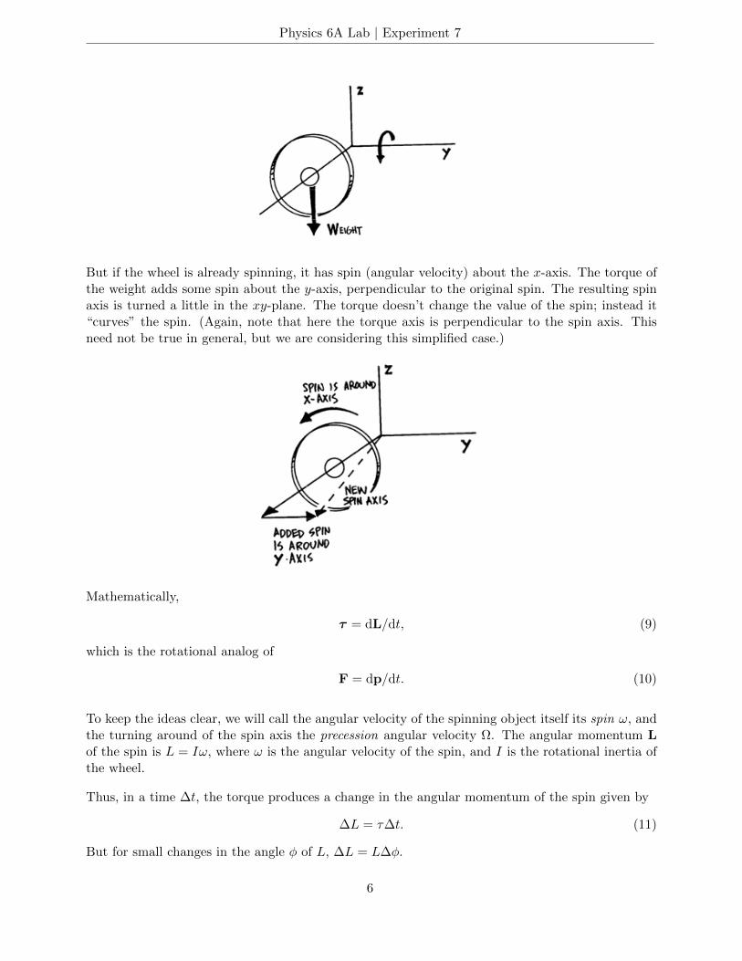
Something similar happens with rotational motion. When the wheel is not spinning, the torquefrom the weight produces an angular velocity about the torque axis, in this case the y-axis.
5
Physics 6A Lab | Experiment 7
But if the wheel is already spinning, it has spin (angular velocity) about the x-axis. The torque ofthe weight adds some spin about the y-axis, perpendicular to the original spin. The resulting spinaxis is turned a little in the xy-plane. The torque doesn’t change the value of the spin; instead it“curves” the spin. (Again, note that here the torque axis is perpendicular to the spin axis. Thisneed not be true in general, but we are considering this simplified case.)
Mathematically,
τ = dL/dt, (9)
which is the rotational analog of
F = dp/dt. (10)
To keep the ideas clear, we will call the angular velocity of the spinning object itself its spin ω, andthe turning around of the spin axis the precession angular velocity Ω. The angular momentum Lof the spin is L = Iω, where ω is the angular velocity of the spin, and I is the rotational inertia ofthe wheel.
Thus, in a time ∆t, the torque produces a change in the angular momentum of the spin given by
∆L = τ∆t. (11)
But for small changes in the angle φ of L, ∆L = L∆φ.
6
Physics 6A Lab | Experiment 7
Thus,
∆L = L∆φ = τ∆t. (12)
The angular velocity of precession Ω = ∆φ/∆t = τ/L, the last equality following from the equationabove. Since L = Iω, we have finally
Ω = τ/Iω. (13)
This then is our basic equation relating the precession angular velocity to the rotational inertia,spin, and torque.
We have shown that precession can be understood from the principles of rotational motion, torque,rotational inertia, angular momentum, etc., and we have even derived the equation for the magnitudeof the precession above. But these concepts must be based on the simpler principles of forceand acceleration. Let’s see if we can understand precession from just the concepts of force andacceleration.
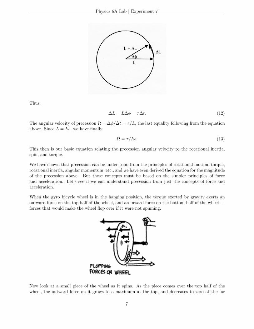
When the gyro bicycle wheel is in the hanging position, the torque exerted by gravity exerts anoutward force on the top half of the wheel, and an inward force on the bottom half of the wheel —forces that would make the wheel flop over if it were not spinning.
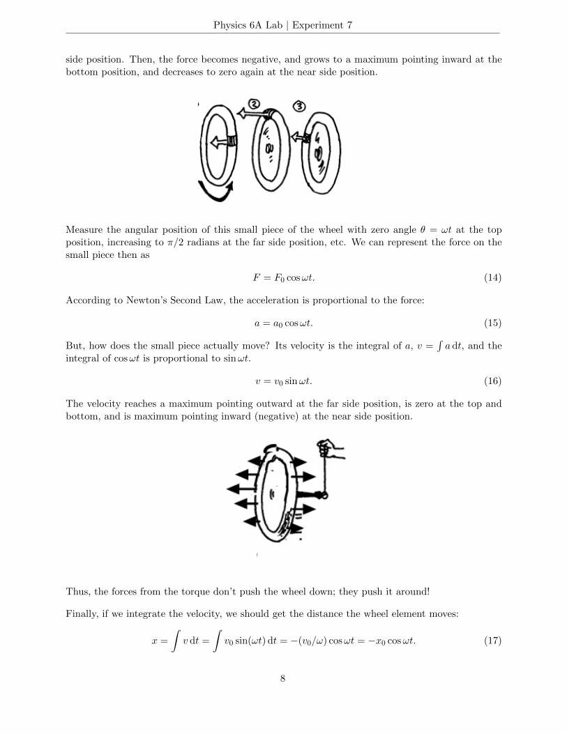
Now look at a small piece of the wheel as it spins. As the piece comes over the top half of thewheel, the outward force on it grows to a maximum at the top, and decreases to zero at the far
7
Physics 6A Lab | Experiment 7
side position. Then, the force becomes negative, and grows to a maximum pointing inward at thebottom position, and decreases to zero again at the near side position.
Measure the angular position of this small piece of the wheel with zero angle θ = ωt at the topposition, increasing to π/2 radians at the far side position, etc. We can represent the force on thesmall piece then as
F = F0 cosωt. (14)
According to Newton’s Second Law, the acceleration is proportional to the force:
a = a0 cosωt. (15)
But, how does the small piece actually move? Its velocity is the integral of a, v =∫a dt, and the
integral of cosωt is proportional to sinωt.
v = v0 sinωt. (16)
The velocity reaches a maximum pointing outward at the far side position, is zero at the top andbottom, and is maximum pointing inward (negative) at the near side position.
Thus, the forces from the torque don’t push the wheel down; they push it around!
Finally, if we integrate the velocity, we should get the distance the wheel element moves:
x =
∫v dt =
∫v0 sin(ωt) dt = −(v0/ω) cosωt = −x0 cosωt. (17)
8
Physics 6A Lab | Experiment 7
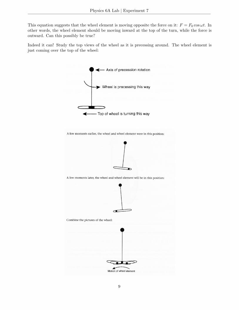
This equation suggests that the wheel element is moving opposite the force on it: F = F0 cosωt. Inother words, the wheel element should be moving inward at the top of the turn, while the force isoutward. Can this possibly be true?
Indeed it can! Study the top views of the wheel as it is precessing around. The wheel element isjust coming over the top of the wheel:
9
Physics 6A Lab | Experiment 7
So you see the wheel element actually does move inward at the top while the force is outward. Infact, the force must be in the outward direction to produce the curved path of the wheel elementin the horizontal plane, just as an inward force produces uniform circular motion. Similarly, atthe bottom of the wheel, the inward force on the wheel element from the torque causes it to curveinward.
PROCEDURE FOR ROTATION
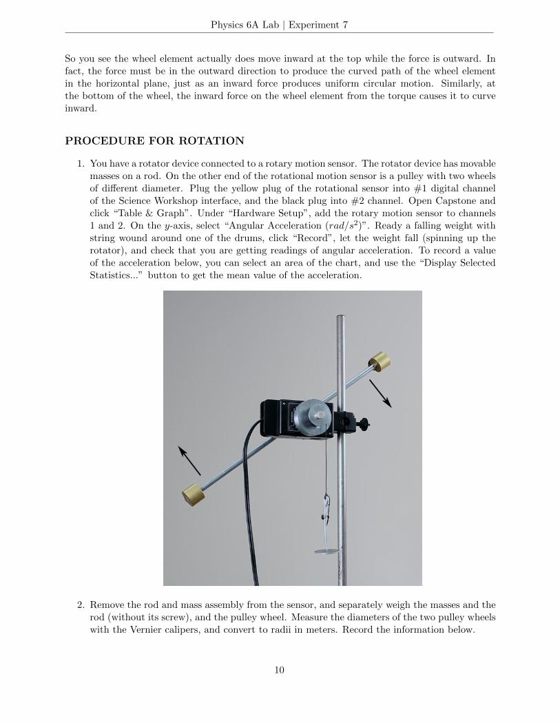
1. You have a rotator device connected to a rotary motion sensor. The rotator device has movablemasses on a rod. On the other end of the rotational motion sensor is a pulley with two wheelsof different diameter. Plug the yellow plug of the rotational sensor into #1 digital channelof the Science Workshop interface, and the black plug into #2 channel. Open Capstone andclick “Table & Graph”. Under “Hardware Setup”, add the rotary motion sensor to channels1 and 2. On the y-axis, select “Angular Acceleration (rad/s2)”. Ready a falling weight withstring wound around one of the drums, click “Record”, let the weight fall (spinning up therotator), and check that you are getting readings of angular acceleration. To record a valueof the acceleration below, you can select an area of the chart, and use the “Display SelectedStatistics...” button to get the mean value of the acceleration.
2. Remove the rod and mass assembly from the sensor, and separately weigh the masses and therod (without its screw), and the pulley wheel. Measure the diameters of the two pulley wheelswith the Vernier calipers, and convert to radii in meters. Record the information below.
10
Physics 6A Lab | Experiment 7
Mass of movable weights in kilograms =
Mass of rod without screw =
Mass of pulley wheel =
Radius of small pulley in meters =
Radius of large pulley in meters =
Warning: In rotational experiments it is especially important to keep mass units (asin rotational inertia) and force units (as in torque) clearly distinguished.
3. According to the textbook, the rotational inertia of a rod of mass m and length l about anaxis perpendicular to the rod and through its center is (1/12)ml2. Calculate the rotationalinertia of the rod. Does it make any difference that the rod is hollow?
I of rod in kg ·m2 =
4. From the mass of the pulley wheel and its volume (which you can calculate from the radiiof the two parts), you can calculate its density. From this you can calculate the rotationalinertia of the pulley wheel. You may have to do some estimating.
I of pulley wheel in kg ·m2 =
5. Do a trial experimental run in which the masses on the rotator are at the ends of the rodso that the rotational inertia is large. Use 100 – 200 g on the weight hanger and wind thestring around the smaller pulley wheel. (This should be the smallest angular accelerationcase.) Notice that the angular acceleration on the graph quickly jumps up and reaches anapproximately constant value. You can select an area of this nearly constant value, and usethe statistics button to get its mean value for the “measured angular acceleration” in thetable below. Now do a trial experimental run in which the masses on the rotator are closeto the center so that the rotational inertia is small. Use 100 – 200 g on the weight hangerand wind the string around the larger pulley wheel so that the torque will spin the rotator upto high speed. (This should be the largest angular acceleration case.) On the graph, noticethat the acceleration quickly reaches a peak, and then falls off with time. Why isn’t the ofacceleration constant in this case? Where on the acceleration curve should you average thevalues of acceleration to get a good result to compare with the predicted acceleration? Howcan you adjust the apparatus or experimental parameters to get a better result for the smallrotational inertia case?
6. Using masses of 50 – 200 grams, hook the string on the pulley pin, wind the string around thepulley, and let the mass fall while you measure the rotational acceleration on the computer. Dothree experimental trials for each case, and average them to find the rotational acceleration.
11
Physics 6A Lab | Experiment 7
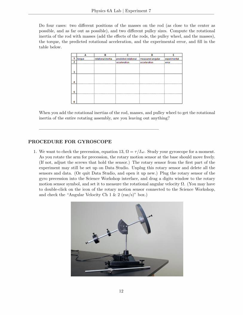
Do four cases: two different positions of the masses on the rod (as close to the center aspossible, and as far out as possible), and two different pulley sizes. Compute the rotationalinertia of the rod with masses (add the effects of the rods, the pulley wheel, and the masses),the torque, the predicted rotational acceleration, and the experimental error, and fill in thetable below.
When you add the rotational inertias of the rod, masses, and pulley wheel to get the rotationalinertia of the entire rotating assembly, are you leaving out anything?
PROCEDURE FOR GYROSCOPE
1. We want to check the precession, equation 13, Ω = τ/Iω. Study your gyroscope for a moment.As you rotate the arm for precession, the rotary motion sensor at the base should move freely.(If not, adjust the screws that hold the sensor.) The rotary sensor from the first part of theexperiment may still be set up on Data Studio. Unplug this rotary sensor and delete all thesensors and data. (Or quit Data Studio, and open it up new.) Plug the rotary sensor of thegyro precession into the Science Workshop interface, and drag a digits window to the rotarymotion sensor symbol, and set it to measure the rotational angular velocity Ω. (You may haveto double-click on the icon of the rotary motion sensor connected to the Science Workshop,and check the “Angular Velocity Ch 1 & 2 (ras/s)” box.)
12
Physics 6A Lab | Experiment 7
Check that you can get a reading of Ω from the computer. Notice that the angular velocityreading in the digits window jumps around, making it difficult to get a definite reading.
Drag a graph window to the rotation sensor, and set to it read angular velocity. Note thatthe reading on the graph also jumps around a little also as the gyro arm turns; but after yourecord the data, you can can select an area of the graph, and use the statistics button to geta mean value for the angular velocity.
2. We will be measuring the angular velocity ω of the gyro wheel with the Digistrobe. TheDigistrobe meter reads in rpm, revolutions per minute. You will need to convert this toradians per second. Determine the conversion factor f in ω = f × (rpm reading).
f =
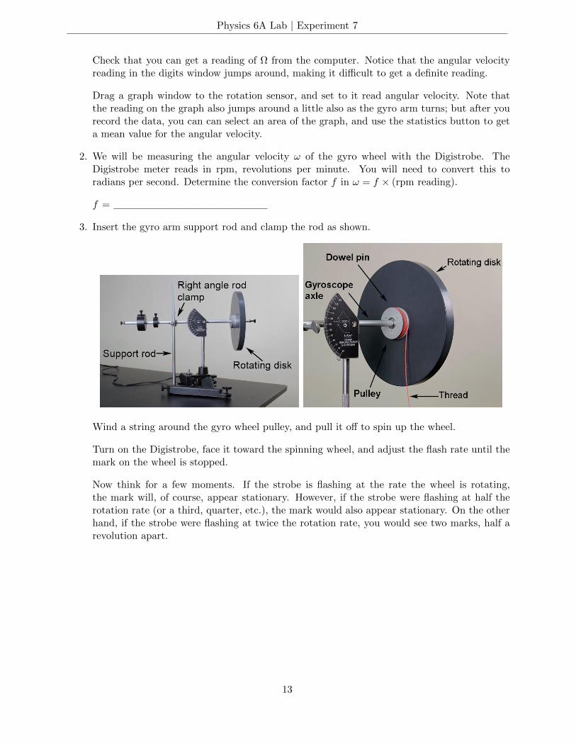
3. Insert the gyro arm support rod and clamp the rod as shown.
Wind a string around the gyro wheel pulley, and pull it off to spin up the wheel.
Turn on the Digistrobe, face it toward the spinning wheel, and adjust the flash rate until themark on the wheel is stopped.
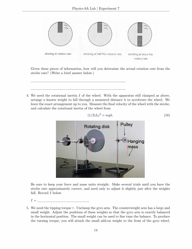
Now think for a few moments. If the strobe is flashing at the rate the wheel is rotating,the mark will, of course, appear stationary. However, if the strobe were flashing at half therotation rate (or a third, quarter, etc.), the mark would also appear stationary. On the otherhand, if the strobe were flashing at twice the rotation rate, you would see two marks, half arevolution apart.
13
Physics 6A Lab | Experiment 7
Given these pieces of information, how will you determine the actual rotation rate from thestrobe rate? (Write a brief answer below.)
4. We need the rotational inertia I of the wheel. With the apparatus still clamped as above,arrange a known weight to fall through a measured distance h to accelerate the wheel. Weleave the exact arrangement up to you. Measure the final velocity of the wheel with the strobe,and calculate the rotational inertia of the wheel from
(1/2)Iω2 = mgh. (18)
Be sure to keep your force and mass units straight. Make several trials until you have thestrobe rate approximately correct, and need only to adjust it slightly just after the weightsfall. Record I below.
I =
5. We need the tipping torque τ . Unclamp the gyro arm. The counterweight arm has a large andsmall weight. Adjust the positions of these weights so that the gyro arm is exactly balancedin the horizontal position. The small weight can be used to fine tune the balance. To producethe turning torque, you will attach the small add-on weight to the front of the gyro wheel.
14

Physics 6A Lab | Experiment 7
Weigh this add-on weight (in newtons!), and measure the distance of its center from the axisof rotation. From these measurements you can calculate the torque.
τ =
6. Now we are ready to precess! Spin up the wheel with a piece of string. Help the gyro startprecessing with the arm horizontal by moving it along in the correct direction at the correctspeed, and then release gently. Measure Ω on the computer, and ω with the strobe.
ω =
measured Ω =
calculated Ω = τ/Iω =
percentage error =
NUTATION
1. Spin up the wheel to high speed using the string. With the add-on weight producing a tippingtorque, hold the shaft horizontally, and release suddenly. The gyroscope undergoes nutation,as in pattern A below.
2. Start again with a smaller torque (just shift the counterweights a little), and with the wheelspinning and arm starting absolutely horizontally (supported by your finger), and then release
15

Physics 6A Lab | Experiment 7
suddenly. (Use the angle scale on the gyro support to determine the 90 horizontal position).When the gyro is precessing and the nutation motion is damping out, the wheel end of the armis somewhat below the horizontal position (read the angle scale). (After several precessionrevolutions, the nutation may be almost completely damped out with the gyro still precessingat a tilted angle. It may take a little experimentation with the torque and wheel speed toproduce this situation.) Can you think of a general physics principle explaining why the gyroarm must be tilted down while the gyro is precessing when started from a horizontal positionwith sudden release? Answer below with brief explanation.
In fact, there is yet another very general physics principle explaining why the gyro arm mustbe tilted down during precession if it is released from the horizontal position. Answer belowwith brief explanation.
ADDITIONAL CREDIT (3 mills)
Perform the precession measurement three times with three significantly different ω’s, and fill inthe table below. Each lab partner must do this separately, doing the computer work him/herself,while directing the other lab partner to assist with the measurements.
16