Rotating Component Modal Analysis and Resonance … · tutorial given at the 2004 Turbomachinery...
24
Copyright© 2013 by Turbomachinery Laboratory, Texas A&M Engineering Experiment Station Proceedings of the Forty-Second Turbomachinery Symposium October 1-3, 2013, Houston, Texas Rotating Component Modal Analysis and Resonance Avoidance – An Update Frank Kushner Consulting Engineer Frank Kushner Consulting Delmont, PA, USA Robert A. Strickland Senior Consulting Engineer The Elliott Group Jeannette, PA, USA Frank Kushner is a consulting engineer and expert witness specializing in dynamics and acoustics testing and analysis. He has had 43 years of experience with industrial turbomachinery, primarily with the Elliott Group, and four years previous experience with the jet engine combustion section development group at Pratt & Whitney Aircraft. He is a previous author for the Ninth, 25th, 29th, 31st, 32nd and 33rd Turbomachinery Symposia, as well as for the ASME. After obtaining a B.S. degree (Mechanical Engineering, 1965) from Indiana Institute of Technology, Mr. Kushner received his M.S. degree (Mechanical Engineering, 1968) from Rensselaer Polytechnic Institute. He is a registered Professional Engineer in the State of Pennsylvania and a member of the ASME and the Vibration Institute. Mr. Kushner holds patents for a blade damping mechanism and a method to prevent one-cell rotating stall in centrifugal compressors. James Shurina Service Engineer The Elliott Group Jeannette, PA, USA James Shurina is a Service Engineer in the Technical Services Department at Elliott Group, in Jeannette, Pennsylvanian. He has 21 years’ experience with industrial turbomachinery including: design, repair, trouble shooting and root cause failure analysis. Mr. Shurina obtained a B.S. degree in Mechanical Engineering Technology from The Pennsylvania State University (1991) and is a registered Professional Engineer in the State of Pennsylvania. Robert A. Strickland is a Senior Consulting Engineer in the Product Development Stress Analysis Group within Elliott Group. He has 36 years’ experience with industrial turbomachinery, primarily in the area of structural integrity. Mr. Strickland obtained a B.S.M.E degree from The Pennsylvania State University in 1973. He is a registered Professional Engineer in the State of Pennsylvania and is a member of the ASME. ABSTRACT Rotating disk and blade fatigue failures are usually a low percentage of failures in most machinery types, but other than coupling / shaft end failures remain some of the most problematic for extensive repairs. High-cycle fatigue failures of rotating disks and blades are not common in most machinery types, but when they occur, they require extensive repairs and resolution can be problematic. This paper is an update of the tutorial given at the 2004 Turbomachinery Symposium focusing on high-cycle fatigue failures in steam turbines, centrifugal and axial gas compressors in refineries and process plants. The failure theories and many of the descriptions for cases given in 2004 have been updated to include blade resonance concerns for potential flow as well as vane and blade wake effects. Disk vibratory modes can be of concern in many machines, but of little concern in others as will be explained. In addition, vibratory modes are included where blades are coupled via communication with the main disk. Over the past decade, fluid-structure-interaction computational methods and modal testing have improved and have been applied to failure theories and problem resolution in the given cases. There is also added information on the effects of mistuning blades and disks, some beneficial and some with serious concerns for increased resonant amplification. Finally, knowledge about acoustic pressure pulsation excitation, particularly for centrifugal impellers at rotating blade passing frequency, has been greatly expanded. A review of acoustics calculations for failure prevention, mainly for high-pressure applications is covered here. INTRODUCTION High cycle fatigue (HCF) and its prevention remains one of the most serious issues for fluid-handling turbomachinery in the oil, gas, petrochemical, and related industries. Relative to this type of equipment, electric utility turbine/generator sets can have consequences that are even more serious; in some cases,
-
Upload
hoangxuyen -
Category
Documents
-
view
227 -
download
3
Transcript of Rotating Component Modal Analysis and Resonance … · tutorial given at the 2004 Turbomachinery...
Copyright© 2013 by Turbomachinery Laboratory, Texas A&M Engineering Experiment Station
Proceedings of the Forty-Second Turbomachinery Symposium October 1-3, 2013, Houston, Texas
Rotating Component Modal Analysis and Resonance Avoidance – An Update
Frank Kushner Consulting Engineer
Frank Kushner Consulting Delmont, PA, USA
Robert A. Strickland
Senior Consulting Engineer The Elliott Group
Jeannette, PA, USA
Frank Kushner is a consulting engineer and expert witness specializing in dynamics and acoustics testing and analysis. He has had 43 years of experience with industrial turbomachinery, primarily with the Elliott Group, and four years previous experience with the jet engine combustion section development group at Pratt & Whitney
Aircraft. He is a previous author for the Ninth, 25th, 29th, 31st, 32nd and 33rd Turbomachinery Symposia, as well as for the ASME. After obtaining a B.S. degree (Mechanical Engineering, 1965) from Indiana Institute of Technology, Mr. Kushner received his M.S. degree (Mechanical Engineering, 1968) from Rensselaer Polytechnic Institute. He is a registered Professional Engineer in the State of Pennsylvania and a member of the ASME and the Vibration Institute. Mr. Kushner holds patents for a blade damping mechanism and a method to prevent one-cell rotating stall in centrifugal compressors.
James Shurina Service Engineer The Elliott Group
Jeannette, PA, USA
James Shurina is a Service Engineer in the Technical Services Department at Elliott Group, in Jeannette, Pennsylvanian. He has 21 years’ experience with industrial turbomachinery including: design, repair, trouble shooting and root cause failure analysis. Mr. Shurina obtained a B.S. degree in Mechanical Engineering Technology from The Pennsylvania State
University (1991) and is a registered Professional Engineer in the State of Pennsylvania.
Robert A. Strickland is a Senior Consulting Engineer in the Product Development Stress Analysis Group within Elliott Group. He has 36 years’ experience with industrial turbomachinery, primarily in the area of structural integrity. Mr. Strickland obtained a B.S.M.E degree from The Pennsylvania State University in 1973. He is a registered Professional Engineer in
the State of Pennsylvania and is a member of the ASME.
ABSTRACT Rotating disk and blade fatigue failures are usually a low percentage of failures in most machinery types, but other than coupling / shaft end failures remain some of the most problematic for extensive repairs. High-cycle fatigue failures of rotating disks and blades are not common in most machinery types, but when they occur, they require extensive repairs and resolution can be problematic. This paper is an update of the tutorial given at the 2004 Turbomachinery Symposium focusing on high-cycle fatigue failures in steam turbines, centrifugal and axial gas compressors in refineries and process plants. The failure theories and many of the descriptions for cases given in 2004 have been updated to include blade resonance concerns for potential flow as well as vane and blade wake effects. Disk vibratory modes can be of concern in many machines, but of little concern in others as will be explained. In addition, vibratory modes are included where blades are coupled via communication with the main disk. Over the past
decade, fluid-structure-interaction computational methods and modal testing have improved and have been applied to failure theories and problem resolution in the given cases. There is also added information on the effects of mistuning blades and disks, some beneficial and some with serious concerns for increased resonant amplification. Finally, knowledge about acoustic pressure pulsation excitation, particularly for centrifugal impellers at rotating blade passing frequency, has been greatly expanded. A review of acoustics calculations for failure prevention, mainly for high-pressure applications is covered here. INTRODUCTION High cycle fatigue (HCF) and its prevention remains one of the most serious issues for fluid-handling turbomachinery in the oil, gas, petrochemical, and related industries. Relative to this type of equipment, electric utility turbine/generator sets can have consequences that are even more serious; in some cases,
Copyright© 2013 by Turbomachinery Laboratory, Texas A&M Engineering Experiment Station
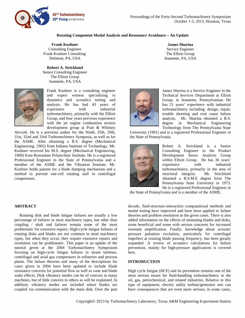
blade and/or disk fracture can be catastrophic as well as a safety issue. An example of this is whenever the last stage blade fundamental mode is equal to twice electrical line frequency; rotor excitation is high from short circuit transient torque in the generator. In some reports, failures of turbine blades are identified as the leading causes of unplanned outages for steam turbines. Front-end turbine blades suffer a high percentage of failures; Bhaduri, et al. (2003), provides some Electric Power Research Institute data. Additional information on steam turbines is given by the International Association of Engineering Insurers (2005) in Figure 1, showing that low pressure (LP) steam turbines blade failures are the highest cause of lost availability. Figure 1. From IMIA (2005) Showing High LP Incidents
McCloskey (2002) gives a comprehensive summary of utility turbine blade and disk troubleshooting including many references. There are similar issues with jet engine designs, their land-based derivatives, and other gas turbines including microturbines (refer to Srinivasan, 1997), but these also have many other issues such as low cycle fatigue analysis and interaction of components with much different operational modes and life cycles (Layton and Marra, 2000). Reports estimate that between 40 and 50 percent of gas turbine outages are due to blade fatigue; besides other sources, combustion pulsation can also give rise to alternating pressure forces. Gas expanders such as those for fluid cat cracker (FCC) processes are a special case with the combustion occurring in the process, but there have been limited blade fatigue problems that are not associated with corrosion, such as described by Dowson, et al. (1995), or catalyst dumps into the turbine inlet casing.
The trends for all losses shown in Clark (1996) for all turbomachines have likely not changed much, although new techniques such as Fluid Structure Interaction (FSI) methods with faster computation have kept pace with trends in higher loading and rotating speeds. FSI combines finite element structural and computation flow analyses for faster direct analysis, e.g. ANSYS / CFX. The materials to be presented primarily for fluid-handling turbomachinery for the oil, gas, petrochemical, and related industries are: • Coverage of resonance responses to consider. • Methods to analyze cantilevered and shrouded blade designs. • Disk modes and disk critical speeds. • Test procedures and correlation with finite element analysis (FEA). • Excitation sources with designs for minimizing loads.
• Campbell and interference diagrams for both blades and disks. • Interaction resonance for bladed disks, including acoustic excitation sources. • Effects of mistuning of disk & blade natural frequencies on forced response and instability.
A historical review of all known interaction resonance effect between blades and vanes for disks will be offered, starting with Kushner (1979). Insight as to why there can be exceptions taken to the specifications for resonance avoidance such as those in API 612 (2005) will also be provided. There are numerous resonance criteria to consider, including many that normally give negligible response and alternating stress. For many potential resonant speeds, environmental effects that reduce endurance strength can sometimes lead to questions of design adequacy. Other resonant points must be avoided for all designs, and some have limits that can only be exceeded if there are improper operation and/or environmental factors. In addition to forced response for turbine and axial compressor blades instability with flow interaction reducing damping is also an issue in component design, whereas instability is extremely rare for radial flow impellers.
Root cause of failure will be described in cases where the designs was suspect with high potential for cause of fatigue, and other cases where failure occurred due to minor resonance combined with manufacturing defects, operation, and/or environment factors such as liquid ingestion and corrosives in gas and steam. These will include several cases for steam turbines and for single and multistage centrifugal compressors, and three cases for axial compressors. This tutorial will present some important views on how components should be designed to meet the service requirements for the required life (20 years per some specifications, with 5-year runs between checks). Of course components must also be fabricated with specified materials, inspected to show they conform to design concepts, and properly operated and maintained. Whenever there are failures, even from improper operation, it is always wise to use the knowledge gained to achieve optimum designs for “fitness-for-service.”
In addition to the lateral mode in the rotor/bearing system of all turbomachinery, and the potential for severe torsional system resonance for some with motors and/or gears, an equally critical aspect is resonance avoidance for structures on the rotor. If the frequency at which variable loads act on a bladed disk coincides with one of the important natural frequencies of the structure, a dangerous situation can occur, leading to rapid failure due to high-cycle fatigue. High-cycle fatigues (HCF) is defined as that which results in cracking or fracture from a large number of stress cycles well below the yield strength of the material, and is associated with fatigue lives greater than 10,000 cycles. Low-cycle fatigue (LCF), such as from thermal effects during startup, is normally not an issue for blades and disks in the machinery discussed in this tutorial. However, severe forces from improper operation, such as continuous surging and/or excessive liquid ingestion, can sometimes cause failure in much less than a million vibration cycles. For many observers, even 10 million cycles (corresponding to the threshold endurance strength for many defect-free, ductile materials) appears to be an unattainably high number of cycles for setting a lower limit. However, consider that structures discussed in this tutorial respond in the
Copyright© 2013 by Turbomachinery Laboratory, Texas A&M Engineering Experiment Station
range of 200 to 10,000 cycles per second. Depending on the severity of excitation and resonant amplification for the structure, a failure can occur in a few minutes to several hours if operating at high loads very close to, or exactly at a resonant operating speed. There have been cases of failures in the first day of operation after startup, as shown by one of the case studies. Resonant response is avoided or minimized by controlling the stimulus or by changing the responding frequency. The stimulus can be controlled by changing the frequency of excitation, changing the strength of the stimulus or changing its relative phase with respect to the blade or bladed disk. The most common method of modifying blade frequency is to tailor the thickness of the blade or disk and other variables affecting frequency such as aspect ratio, taper, number and thickness of blades, and radius ratio of the disk outer-to inner-diameters. More drastic modifications to blade frequency include using one of many damping methods such as change to a friction damping mechanism at part span, or using a tip shroud that incorporates damping and/or phase cancellation.
In some cases, natural frequency variations, even for constant speed applications of load, may be greater than an acceptable band; in these cases the blades must be designed with sufficient stiffness, higher strength materials, and/or higher damping to limit stresses whenever blades operate at resonance. HCF failures can occur when these conditions are not met; or if a forcing function becomes excessive, such as from upstream or downstream blade or vane damage; operation at off-design causing rotating stall, surge, flutter, or other damage such as from blade tip rubs. In some cases there can be simultaneous sources of excitation affecting the same or different modes. Manufacturing tolerances and fabrication variations can influence natural frequencies for a blade assembly; corrosion, wear, and erosion can also reduce resonant frequency margins and/or endurance strength over time. Either of these conditions, or a combination of these conditions, can result in high-cycle fatigue initiation and propagation. Crack initiation, followed by secondary resonant points can also assist in HCF propagation. The cracked structure has lower stress intensity and the required number of cycles for crack growth compared to initiation. If inspections do not find cracks to abate further propagation, crack growth can easily reach its fast fracture limit. Many machines have been shut down due to changes in monitored vibration data before a catastrophic wreck. Thankfully, ductile materials help to mitigate this concern. In some cases, cracks could lower the resonant frequency such that the structure moves away from the resonant speed. This change could give some relief, especially for constant-speed machines such as turbine/generator sets. In other cases, sometimes after a long period, resonance and/or the same or another speed change or off-design upset giving high loads can reoccur, causing the “beach-mark” patterns (showing start /stop events on a fractured surface).
The tutorial includes an initial description of resonance, using examples for blades and disks. There is also a description of modal analysis of rotating structures that could apply to other machinery, outlining which vibratory modes are especially important. The risks of resonance vary for different applications; each major type of rotating machine, centrifugal and axial compressors handling gaseous fluids is more fully covered in the case studies.
REVIEW OF BLADE AND DISK RESONANCE
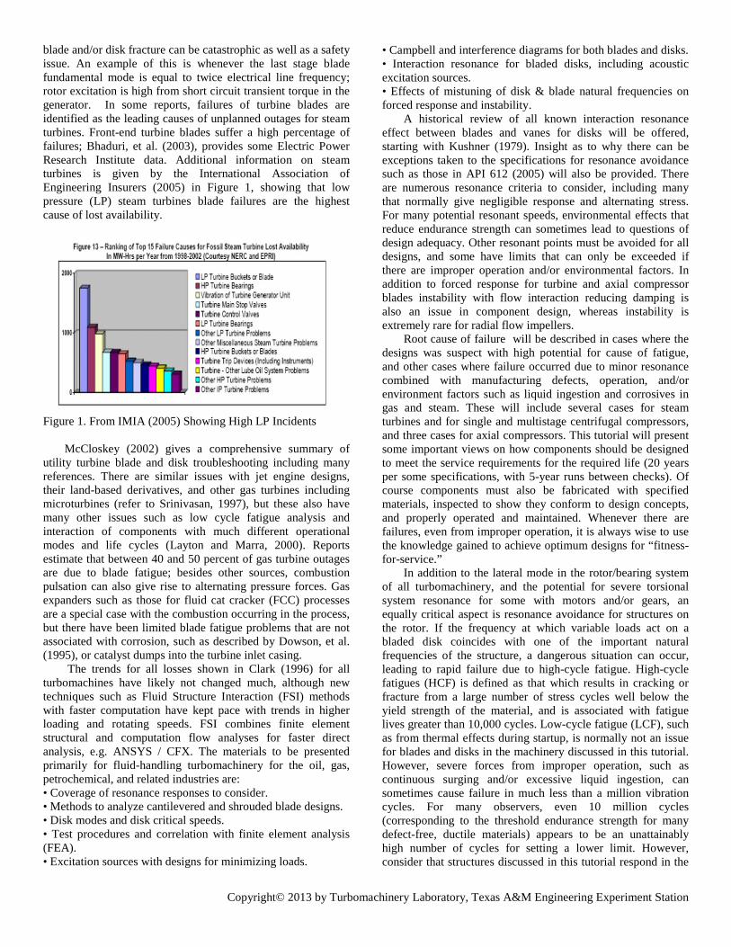
Machinery discussed in this tutorial typically has excitation potential of either blade or disk modes; however some designs could have coupled disk/blade modes as do many jet engine designs and gas turbine derivatives. As in all aspects of vibration, it is very important to always consider phase, not just amplitude and frequency. Natural frequencies with finite element programs are utilized for design, with much less testing as compared to 20 years ago. Correlation tests as described in Appendix A of Kushner (2004) are always beneficial, especially for critical resonant modes such as the blade leading edge mode for impellers (to be reviewed later). Figure 2. FEA Model of Covered Impeller with Full Inducer and Curved, 3-D Blades.
For modal analysis using finite element analysis, equations
of motion apply, and especially for complex structures, the analysis requires careful modeling (Figure 2) with proper techniques, including boundary conditions. In order to obtain relative stresses for higher order modes, the entire impeller may require modeling. Modal analysis of a cyclic symmetric structure to determine nodal diameter frequencies can be computed by modeling only one sector per the finite element computer code (Kohnke, 1999). Nodal diameter mode shapes, commonly referred to as nodal diameters, contain lines of zero out-of-plane displacements, which cross the entire disk. The number of nodal diameters, n, is an integer that determines the variation in the value of a single degree of freedom at points spaced at a circumferential angle—equal to the basic sector angle (Theta). For a number of nodal diameters equal to n, this variation is described by the function, cos [n (Theta)]. This definition allows a varying number of waves to exist around the circumference for a given nodal diameter.
Constraint relationships can be defined to relate the displacements of one edge of the cut boundary to the other edge. This allows for calculation of natural frequencies related to a given number of nodal diameters. The basic sector is used

Copyright© 2013 by Turbomachinery Laboratory, Texas A&M Engineering Experiment Station
twice, once to satisfy the required constraint relationships and once to obtain nodal displacements. The analysis results in pairs of frequencies for each nodal diameter solution. Using this technique, it is possible to obtain solutions for up to a number of nodal diameters, n, where n = B / 2. For an even number of blades, B, this would be B / 2; for an odd number of blades this would be (B-1) / 2. Methods are given to evaluate these frequencies for both static and dynamic (stress stiffened) conditions. More complex modes require a model of the entire impeller as shown in Case B-6, Kushner (2004).
Cantilevered Blade Design and Resonance Avoidance
In axial machinery, rotating blades have the most difficult
task of HCF avoidance, as they are most compliant. This is true not only in axial compressors, but also in non-shrouded stages of both steam turbines and centrifugal compressors. Freestanding, cantilevered blades come in many forms and sizes. Shorter blades usually do not have much twisting along the profile length and have three fairly independent modes: fundamental tangential, fundamental axial and fundamental torsional (refer to Appendix A of Kushner (2004). Higher modes have nodal lines and phase changes along the length and width, and thus inherent phase cancellation for most cases. The fundamental tangential mode is not only the most compliant, but typically experiences the highest excitation forces as the direction of force (a percentage of steady forces) aligns with the predominant steady gas force that “drives” the machine. Many blades are canted so that tangential forces can assist in excitation of the fundamental axial mode, but axial forces are lower and axial modes are less compliant, giving lower dynamic stresses. Torsional modes also present less concern, as there is a node line along the blade, such that the exciting force on the leading edge is nearly out of phase with that on the trailing side. For short blades, axial and torsional modes can be at less than one tenth of the concern for tangential bending modes. There are exceptions, such as from axial forces on a highly-loaded reaction-bladed turbine stage.
Medium length blades, such as the middle stages of steam turbines, typically have fewer problems as nozzle passing frequency is avoided; resonance of the first modes would only be equal to lower harmonics of speed where severe non-uniformity of nozzle throats is the main issue, along with the potential for excessive corrosion in transition stages (one of the cases below). Higher order modes could also present problems with excessive corrosion.
Longer cantilevered blades in the rear of steam turbines (Figure 3) and also those without friction damping in the front-end of axial compressors can have resonance potential for all three directions. In modern machines, longer blades have significant twist and larger chord widths such that the modes for the three directions are coupled. In fact, there can be higher axial motion as compared to tangential at the blade tip for the lowest frequency mode; thus higher axial forces for a reaction-type stage of a steam turbine could give relatively more response at resonance. In addition, the fundamental modes also have the potential for flow-incidence related flutter. The longer free-standing blades in many steam turbine-generator exhaust ends have the first few modes carefully tuned. There is less risk with gas expanders since inlet connections, other than support
struts, are axial, thereby reducing harmonic excitation. The high number of inlet vanes only minimally excites higher order modes.
Figure 3. Turbine Last Stage Zig-Zag Damping Pins.
Free-standing, cantilevered blades used for open impellers
also have much more risk for HCF than fixed-fixed blades in covered impellers. When selecting inlet guide vanes, the fundamental bending and sometimes the higher modes with nodal lines must be considered. The number of inlet guide vanes thus becomes a design variable for integrally-geared compressors and radial-inflow turbines. As impeller sizes increase, the leading edge flapping mode can become a design issue for covered impellers and should be addressed. The fixed-fixed mode is not very compliant as compared to a cantilevered blade. Some designs having first order resonance have run in fixed-fixed mode, and there are thousands running with resonance of the same mode, but excited by two times upstream vanes. However as shown by Schiffer and Syed (2006), Blade Leading Edge Mode (BLEM) resonance was the cause of two failures, requiring a change from 16 to 12 inlet guide vanes. Cases such as described by Singh, et al. (2003), and Phillips, et al. (2003), for two times number of inlet vane excitation likely were due to other mitigating factors raising questions such as:
• Was operation within the specified operating map? • How much liquid was really being ingested to potentially
aggravate the wakes from upstream vanes and reduce aerodynamic damping? Shrouded Turbine Blades Phase cancellation has been used for many years to mitigate resonance in steam turbines and other machines. Prohl (1958) and Weaver and Prohl (1958) give one of the best reviews on this subject. Phase can be easily described by pushing a child on a swing. One pushes in the same direction and time (same frequency) that the child is moving away from you; stopping motion is with opposite phase. By tying turbine blades into packets, phase cancellation can be optimized for a given mode, so that some blades in a packet are out of phase with the exciting forces.
Figures 4 and 5 illustrate how forces (F) can either line up or be out-of-phase with motion. Phase cancellation is likely the
Copyright© 2013 by Turbomachinery Laboratory, Texas A&M Engineering Experiment Station
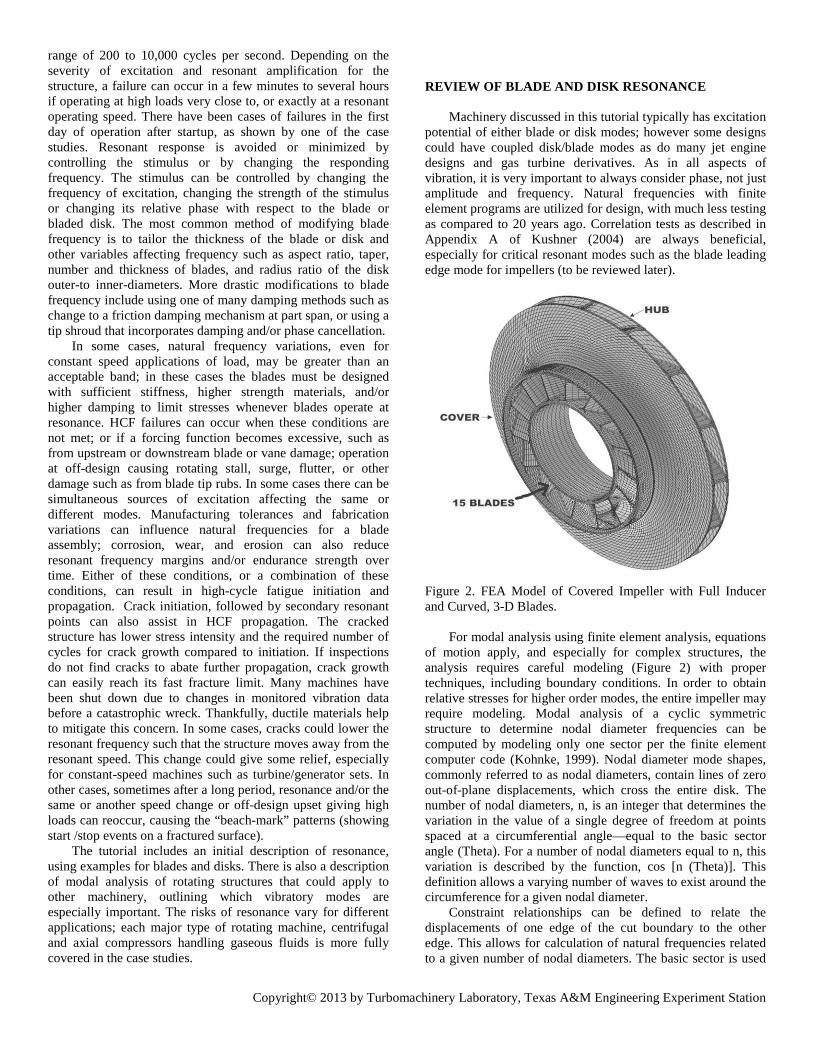
most successful method used over the years for reducing the number of HCF incidents in steam turbines.
Figure 4. Blade Packet Fundamental Mode All Blades In Phase With Excitation Force (F) Figure 5. Blade Packet Fundamental Mode: Some Blades In Phase With Excitation Force (F); Some Blades Out-Of-Phase With Excitation.
Response from partial-admission inlets causing non-uniform loading is also greatly reduced by shrouding. APPENDIX A gives a simplified method to check for optimum blade number per packet for the fundamental mode where all blades vibrate in phase with the same amplitude. Similar procedures, considering amplitude and phase changes, can be done for higher modes, as shown in Figure 6. An example is shown in APPENDIX A where the response factor can be forced to give zero response for fundamental modes. With the varieties of designs, it is impossible to obtain complete cancellation for every resonant mode, but typically, designs with resonant factors down to at least 0.20, i.e., dynamic stress reduced by a factor of five, as compared to free-standing blades can be used. However shrouding blades into packets also gives additional coupled modes to be concerned with as shown by Weaver and Prohl (1958) and many others, with actual strain gage data at speed in Heymann (1968).
Figure 6. Out-OF-Phase Mode; Some Blades In Phase With Excitation (F); Some Blades Out-Of-Phase With Excitation.
By changing number of nozzles, some blades in a packet
are excited in-phase at the same time other blades are vibrating out-of-phase with exciting forces. The dual forces cancel much of the excitation and resonance with nozzle passing frequency can often be accommodated within the operating speed range. The turbines on the Queen Elizabeth 2 ocean liner had failures due to higher modes for non-optimized packet configurations.
Effective resonant response factors for higher fixed-supported modes are typically only 20 percent of that for the fundamental mode, so unusual conditions are necessary to create a worrisome response. A poor design would have first out-of-phase mode resonant with one-half the number of nozzles as compared to blades, and some particular values for blade number per packet. However if the first out-of-phase mode is the one resonant with nozzle passing frequency, nearly equal spacing could be a good design as forces cancel out much of the excitation, resulting in a low resonant response factor. However, equal numbers with equal spacing is not a good design. An out-of-phase mode in resonance with upstream vane passing frequency could have the number of blades per packet optimized giving a different response factor and/or frequency.
Some manufacturers standardize the number of blades per packet, but it is sometimes very important to optimize a given stage. For example, a high pressure, high temperature Curtis stage with 64 rotating blades and 71 inlet vanes should have eight blades per packet, not four per packet, if a fundamental mode is resonant with 71 times speed. If it is not resonant, it could be acceptable to use four blades per packet. Besides shrouding shorter blades to reduce response at high frequencies from inlet vane passing frequency, “long-arc” blading can be used to minimize response of fundamental modes (refer to Ortolano, et al., 1981; and McCloskey, 2002). In a low-pressure turbine stage, instead of using 24 packets with four blades in each, a six-per-revolution resonance could have six packets with 16 blades per packet around the circumference. APPENDIX A can be used to verify that the response factor would be zero when using N (excitation harmonic) equal to 6. If the shroud could not physically fit over the tangs during assembly but could fit with eight packets, the assembly can still have fairly low response factor. Friction Damping Methods
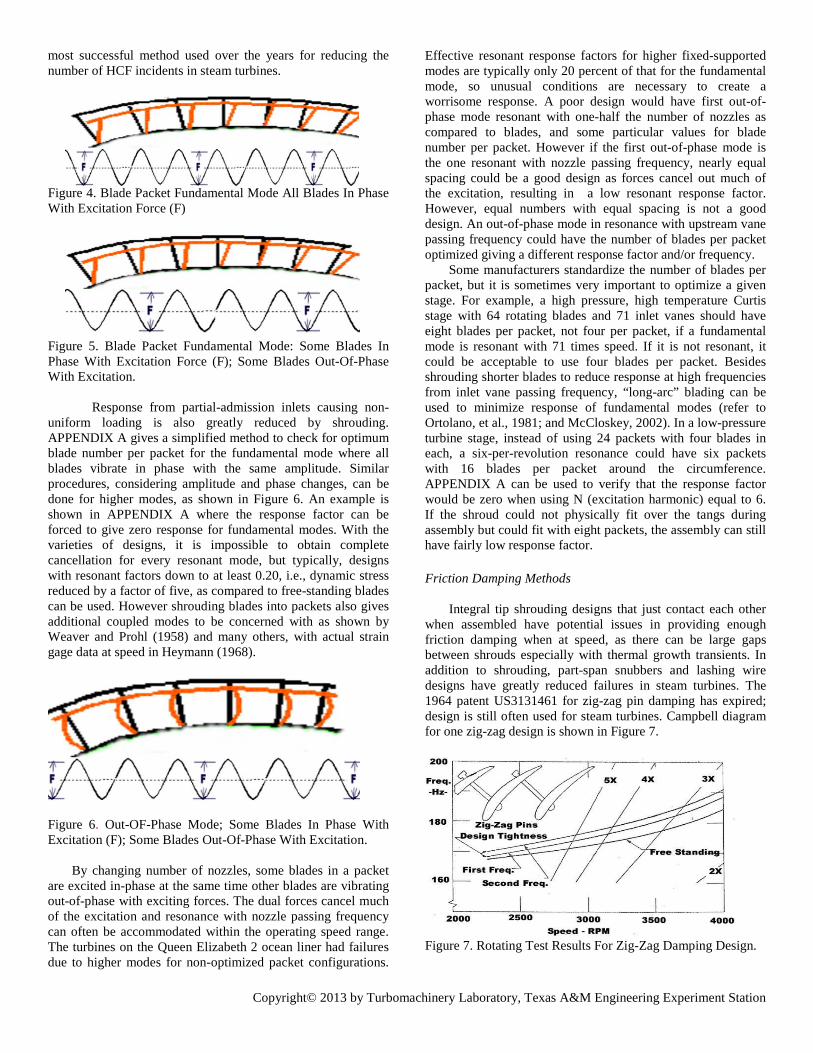
Integral tip shrouding designs that just contact each other when assembled have potential issues in providing enough friction damping when at speed, as there can be large gaps between shrouds especially with thermal growth transients. In addition to shrouding, part-span snubbers and lashing wire designs have greatly reduced failures in steam turbines. The 1964 patent US3131461 for zig-zag pin damping has expired; design is still often used for steam turbines. Campbell diagram for one zig-zag design is shown in Figure 7. Figure 7. Rotating Test Results For Zig-Zag Damping Design.
Copyright© 2013 by Turbomachinery Laboratory, Texas A&M Engineering Experiment Station
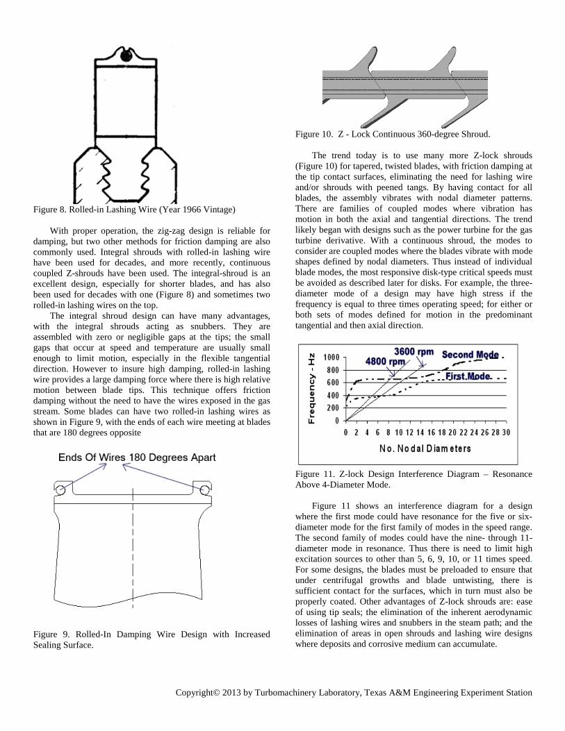
Figure 8. Rolled-in Lashing Wire (Year 1966 Vintage)
With proper operation, the zig-zag design is reliable for damping, but two other methods for friction damping are also commonly used. Integral shrouds with rolled-in lashing wire have been used for decades, and more recently, continuous coupled Z-shrouds have been used. The integral-shroud is an excellent design, especially for shorter blades, and has also been used for decades with one (Figure 8) and sometimes two rolled-in lashing wires on the top.
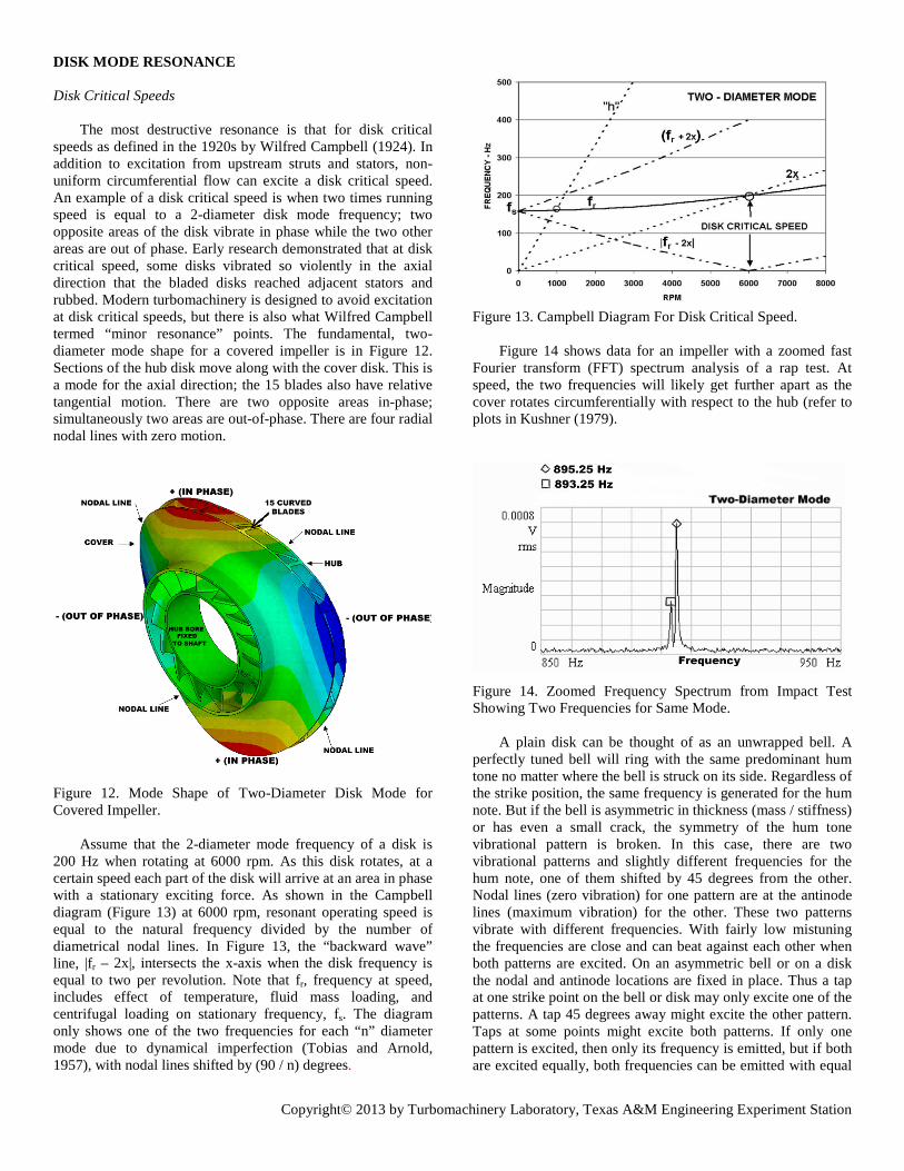
The integral shroud design can have many advantages, with the integral shrouds acting as snubbers. They are assembled with zero or negligible gaps at the tips; the small gaps that occur at speed and temperature are usually small enough to limit motion, especially in the flexible tangential direction. However to insure high damping, rolled-in lashing wire provides a large damping force where there is high relative motion between blade tips. This technique offers friction damping without the need to have the wires exposed in the gas stream. Some blades can have two rolled-in lashing wires as shown in Figure 9, with the ends of each wire meeting at blades that are 180 degrees opposite Figure 9. Rolled-In Damping Wire Design with Increased Sealing Surface.
Figure 10. Z - Lock Continuous 360-degree Shroud.
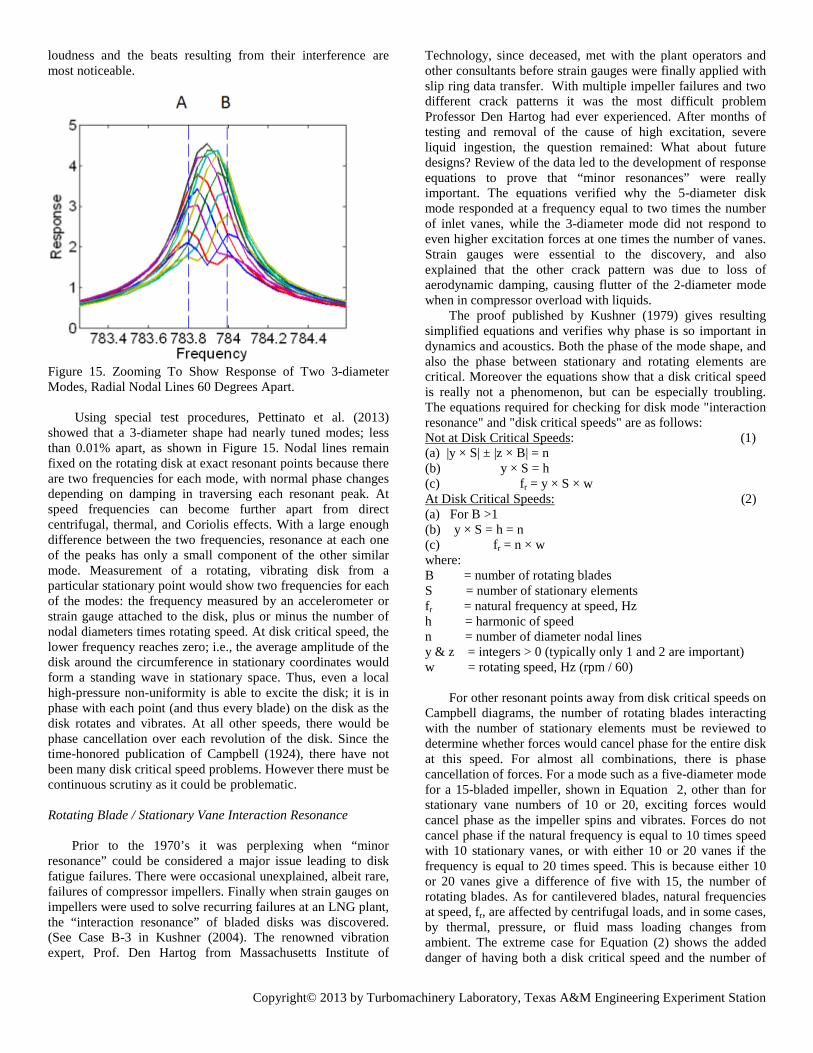
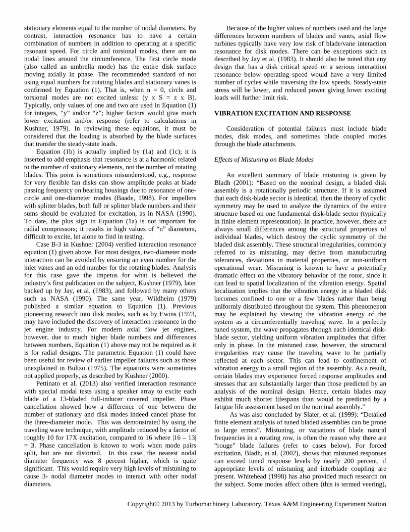
The trend today is to use many more Z-lock shrouds (Figure 10) for tapered, twisted blades, with friction damping at the tip contact surfaces, eliminating the need for lashing wire and/or shrouds with peened tangs. By having contact for all blades, the assembly vibrates with nodal diameter patterns. There are families of coupled modes where vibration has motion in both the axial and tangential directions. The trend likely began with designs such as the power turbine for the gas turbine derivative. With a continuous shroud, the modes to consider are coupled modes where the blades vibrate with mode shapes defined by nodal diameters. Thus instead of individual blade modes, the most responsive disk-type critical speeds must be avoided as described later for disks. For example, the three-diameter mode of a design may have high stress if the frequency is equal to three times operating speed; for either or both sets of modes defined for motion in the predominant tangential and then axial direction. Figure 11. Z-lock Design Interference Diagram – Resonance Above 4-Diameter Mode.
Figure 11 shows an interference diagram for a design where the first mode could have resonance for the five or six-diameter mode for the first family of modes in the speed range. The second family of modes could have the nine- through 11-diameter mode in resonance. Thus there is need to limit high excitation sources to other than 5, 6, 9, 10, or 11 times speed. For some designs, the blades must be preloaded to ensure that under centrifugal growths and blade untwisting, there is sufficient contact for the surfaces, which in turn must also be properly coated. Other advantages of Z-lock shrouds are: ease of using tip seals; the elimination of the inherent aerodynamic losses of lashing wires and snubbers in the steam path; and the elimination of areas in open shrouds and lashing wire designs where deposits and corrosive medium can accumulate.
Copyright© 2013 by Turbomachinery Laboratory, Texas A&M Engineering Experiment Station
DISK MODE RESONANCE Disk Critical Speeds
The most destructive resonance is that for disk critical speeds as defined in the 1920s by Wilfred Campbell (1924). In addition to excitation from upstream struts and stators, non-uniform circumferential flow can excite a disk critical speed. An example of a disk critical speed is when two times running speed is equal to a 2-diameter disk mode frequency; two opposite areas of the disk vibrate in phase while the two other areas are out of phase. Early research demonstrated that at disk critical speed, some disks vibrated so violently in the axial direction that the bladed disks reached adjacent stators and rubbed. Modern turbomachinery is designed to avoid excitation at disk critical speeds, but there is also what Wilfred Campbell termed “minor resonance” points. The fundamental, two-diameter mode shape for a covered impeller is in Figure 12. Sections of the hub disk move along with the cover disk. This is a mode for the axial direction; the 15 blades also have relative tangential motion. There are two opposite areas in-phase; simultaneously two areas are out-of-phase. There are four radial nodal lines with zero motion. Figure 12. Mode Shape of Two-Diameter Disk Mode for Covered Impeller.
Assume that the 2-diameter mode frequency of a disk is 200 Hz when rotating at 6000 rpm. As this disk rotates, at a certain speed each part of the disk will arrive at an area in phase with a stationary exciting force. As shown in the Campbell diagram (Figure 13) at 6000 rpm, resonant operating speed is equal to the natural frequency divided by the number of diametrical nodal lines. In Figure 13, the “backward wave” line, |fr – 2x|, intersects the x-axis when the disk frequency is equal to two per revolution. Note that fr, frequency at speed, includes effect of temperature, fluid mass loading, and centrifugal loading on stationary frequency, fs. The diagram only shows one of the two frequencies for each “n” diameter mode due to dynamical imperfection (Tobias and Arnold, 1957), with nodal lines shifted by (90 / n) degrees.
Figure 13. Campbell Diagram For Disk Critical Speed. Figure 14 shows data for an impeller with a zoomed fast
Fourier transform (FFT) spectrum analysis of a rap test. At speed, the two frequencies will likely get further apart as the cover rotates circumferentially with respect to the hub (refer to plots in Kushner (1979). Figure 14. Zoomed Frequency Spectrum from Impact Test Showing Two Frequencies for Same Mode.
A plain disk can be thought of as an unwrapped bell. A perfectly tuned bell will ring with the same predominant hum tone no matter where the bell is struck on its side. Regardless of the strike position, the same frequency is generated for the hum note. But if the bell is asymmetric in thickness (mass / stiffness) or has even a small crack, the symmetry of the hum tone vibrational pattern is broken. In this case, there are two vibrational patterns and slightly different frequencies for the hum note, one of them shifted by 45 degrees from the other. Nodal lines (zero vibration) for one pattern are at the antinode lines (maximum vibration) for the other. These two patterns vibrate with different frequencies. With fairly low mistuning the frequencies are close and can beat against each other when both patterns are excited. On an asymmetric bell or on a disk the nodal and antinode locations are fixed in place. Thus a tap at one strike point on the bell or disk may only excite one of the patterns. A tap 45 degrees away might excite the other pattern. Taps at some points might excite both patterns. If only one pattern is excited, then only its frequency is emitted, but if both are excited equally, both frequencies can be emitted with equal
Copyright© 2013 by Turbomachinery Laboratory, Texas A&M Engineering Experiment Station
loudness and the beats resulting from their interference are most noticeable.
Figure 15. Zooming To Show Response of Two 3-diameter Modes, Radial Nodal Lines 60 Degrees Apart. Using special test procedures, Pettinato et al. (2013) showed that a 3-diameter shape had nearly tuned modes; less than 0.01% apart, as shown in Figure 15. Nodal lines remain fixed on the rotating disk at exact resonant points because there are two frequencies for each mode, with normal phase changes depending on damping in traversing each resonant peak. At speed frequencies can become further apart from direct centrifugal, thermal, and Coriolis effects. With a large enough difference between the two frequencies, resonance at each one of the peaks has only a small component of the other similar mode. Measurement of a rotating, vibrating disk from a particular stationary point would show two frequencies for each of the modes: the frequency measured by an accelerometer or strain gauge attached to the disk, plus or minus the number of nodal diameters times rotating speed. At disk critical speed, the lower frequency reaches zero; i.e., the average amplitude of the disk around the circumference in stationary coordinates would form a standing wave in stationary space. Thus, even a local high-pressure non-uniformity is able to excite the disk; it is in phase with each point (and thus every blade) on the disk as the disk rotates and vibrates. At all other speeds, there would be phase cancellation over each revolution of the disk. Since the time-honored publication of Campbell (1924), there have not been many disk critical speed problems. However there must be continuous scrutiny as it could be problematic. Rotating Blade / Stationary Vane Interaction Resonance
Prior to the 1970’s it was perplexing when “minor resonance” could be considered a major issue leading to disk fatigue failures. There were occasional unexplained, albeit rare, failures of compressor impellers. Finally when strain gauges on impellers were used to solve recurring failures at an LNG plant, the “interaction resonance” of bladed disks was discovered. (See Case B-3 in Kushner (2004). The renowned vibration expert, Prof. Den Hartog from Massachusetts Institute of
Technology, since deceased, met with the plant operators and other consultants before strain gauges were finally applied with slip ring data transfer. With multiple impeller failures and two different crack patterns it was the most difficult problem Professor Den Hartog had ever experienced. After months of testing and removal of the cause of high excitation, severe liquid ingestion, the question remained: What about future designs? Review of the data led to the development of response equations to prove that “minor resonances” were really important. The equations verified why the 5-diameter disk mode responded at a frequency equal to two times the number of inlet vanes, while the 3-diameter mode did not respond to even higher excitation forces at one times the number of vanes. Strain gauges were essential to the discovery, and also explained that the other crack pattern was due to loss of aerodynamic damping, causing flutter of the 2-diameter mode when in compressor overload with liquids.
The proof published by Kushner (1979) gives resulting simplified equations and verifies why phase is so important in dynamics and acoustics. Both the phase of the mode shape, and also the phase between stationary and rotating elements are critical. Moreover the equations show that a disk critical speed is really not a phenomenon, but can be especially troubling. The equations required for checking for disk mode "interaction resonance" and "disk critical speeds" are as follows: Not at Disk Critical Speeds: (1) (a) |y × S| ± |z × B| = n (b) y × S = h (c) fr = y × S × w At Disk Critical Speeds: (2) (a) For B >1 (b) y × S = h = n (c) fr = n × w where: B = number of rotating blades S = number of stationary elements fr = natural frequency at speed, Hz h = harmonic of speed n = number of diameter nodal lines y & z = integers > 0 (typically only 1 and 2 are important) w = rotating speed, Hz (rpm / 60)
For other resonant points away from disk critical speeds on
Campbell diagrams, the number of rotating blades interacting with the number of stationary elements must be reviewed to determine whether forces would cancel phase for the entire disk at this speed. For almost all combinations, there is phase cancellation of forces. For a mode such as a five-diameter mode for a 15-bladed impeller, shown in Equation 2, other than for stationary vane numbers of 10 or 20, exciting forces would cancel phase as the impeller spins and vibrates. Forces do not cancel phase if the natural frequency is equal to 10 times speed with 10 stationary vanes, or with either 10 or 20 vanes if the frequency is equal to 20 times speed. This is because either 10 or 20 vanes give a difference of five with 15, the number of rotating blades. As for cantilevered blades, natural frequencies at speed, fr, are affected by centrifugal loads, and in some cases, by thermal, pressure, or fluid mass loading changes from ambient. The extreme case for Equation (2) shows the added danger of having both a disk critical speed and the number of
Copyright© 2013 by Turbomachinery Laboratory, Texas A&M Engineering Experiment Station
stationary elements equal to the number of nodal diameters. By contrast, interaction resonance has to have a certain combination of numbers in addition to operating at a specific resonant speed. For circle and torsional modes, there are no nodal lines around the circumference. The first circle mode (also called an umbrella mode) has the entire disk surface moving axially in phase. The recommended standard of not using equal numbers for rotating blades and stationary vanes is confirmed by Equation (1). That is, when n = 0, circle and torsional modes are not excited unless: (y x S = z x B). Typically, only values of one and two are used in Equation (1) for integers, “y” and/or “z”; higher factors would give much lower excitation and/or response (refer to calculations in Kushner, 1979). In reviewing these equations, it must be considered that the loading is absorbed by the blade surfaces that transfer the steady-state loads.
Equation (1b) is actually implied by (1a) and (1c); it is inserted to add emphasis that resonance is at a harmonic related to the number of stationary elements, not the number of rotating blades. This point is sometimes misunderstood, e.g., response for very flexible fan disks can show amplitude peaks at blade passing frequency on bearing housings due to resonance of one-circle and one-diameter modes (Baade, 1998). For impellers with splitter blades, both full or splitter blade numbers and their sums should be evaluated for excitation, as in NASA (1990). To date, the plus sign in Equation (1a) is not important for radial compressors; it results in high values of “n” diameters, difficult to excite, let alone to find in testing.
Case B-3 in Kushner (2004) verified interaction resonance equation (1) given above. For most designs, two-diameter mode interaction can be avoided by ensuring an even number for the inlet vanes and an odd number for the rotating blades. Analysis for this case gave the impetus for what is believed the industry’s first publication on the subject, Kushner (1979), later backed up by Jay, et al. (1983), and followed by many others such as NASA (1990). The same year, Wildheim (1979) published a similar equation to Equation (1). Previous pioneering research into disk modes, such as by Ewins (1973, may have included the discovery of interaction resonance in the jet engine industry. For modern axial flow jet engines, however, due to much higher blade numbers and differences between numbers, Equation (1) above may not be required as it is for radial designs. The parametric Equation (1) could have been useful for review of earlier impeller failures such as those unexplained in Bultzo (1975). The equations were sometimes not applied properly, as described by Kushner (2000).
Pettinato et al. (2013) also verified interaction resonance with special modal tests using a speaker array to excite each blade of a 13-bladed full-inducer covered impeller. Phase cancellation showed how a difference of one between the number of stationary and disk modes indeed cancel phase for the three-diameter mode. This was demonstrated by using the traveling wave technique, with amplitude reduced by a factor of roughly 10 for 17X excitation, compared to 16 where |16 – 13| = 3. Phase cancellation is known to work when mode pairs split, but are not distorted. In this case, the nearest nodal diameter frequency was 8 percent higher, which is quite significant. This would require very high levels of mistuning to cause 3- nodal diameter modes to interact with other nodal diameters.
Because of the higher values of numbers used and the large differences between numbers of blades and vanes, axial flow turbines typically have very low risk of blade/vane interaction resonance for disk modes. There can be exceptions such as described by Jay et al. (1983). It should also be noted that any design that has a disk critical speed or a serious interaction resonance below operating speed would have a very limited number of cycles while traversing the low speeds. Steady-state stress will be lower, and reduced power giving lower exciting loads will further limit risk.
VIBRATION EXCITATION AND RESPONSE
Consideration of potential failures must include blade
modes, disk modes, and sometimes blade coupled modes through the blade attachments. Effects of Mistuning on Blade Modes
An excellent summary of blade mistuning is given by
Bladh (2001): “Based on the nominal design, a bladed disk assembly is a rotationally periodic structure. If it is assumed that each disk-blade sector is identical, then the theory of cyclic symmetry may be used to analyze the dynamics of the entire structure based on one fundamental disk-blade sector (typically in finite element representation). In practice, however, there are always small differences among the structural properties of individual blades, which destroy the cyclic symmetry of the bladed disk assembly. These structural irregularities, commonly referred to as mistuning, may derive from manufacturing tolerances, deviations in material properties, or non-uniform operational wear. Mistuning is known to have a potentially dramatic effect on the vibratory behavior of the rotor, since it can lead to spatial localization of the vibration energy. Spatial localization implies that the vibration energy in a bladed disk becomes confined to one or a few blades rather than being uniformly distributed throughout the system. This phenomenon may be explained by viewing the vibration energy of the system as a circumferentially traveling wave. In a perfectly tuned system, the wave propagates through each identical disk-blade sector, yielding uniform vibration amplitudes that differ only in phase. In the mistuned case, however, the structural irregularities may cause the traveling wave to be partially reflected at each sector. This can lead to confinement of vibration energy to a small region of the assembly. As a result, certain blades may experience forced response amplitudes and stresses that are substantially larger than those predicted by an analysis of the nominal design. Hence, certain blades may exhibit much shorter lifespans than would be predicted by a fatigue life assessment based on the nominal assembly.”
As was also concluded by Slater, et al. (1999): “Detailed finite element analysis of tuned bladed assemblies can be prone to large errors”. Mistuning, or variations of blade natural frequencies in a rotating row, is often the reason why there are “rouge” blade failures (refer to cases below). For forced excitation, Bladh, et al. (2002), shows that mistuned responses can exceed tuned response levels by nearly 200 percent, if appropriate levels of mistuning and interblade coupling are present. Whitehead (1998) has also provided much research on the subject. Some modes affect others (this is termed veering),
Copyright© 2013 by Turbomachinery Laboratory, Texas A&M Engineering Experiment Station
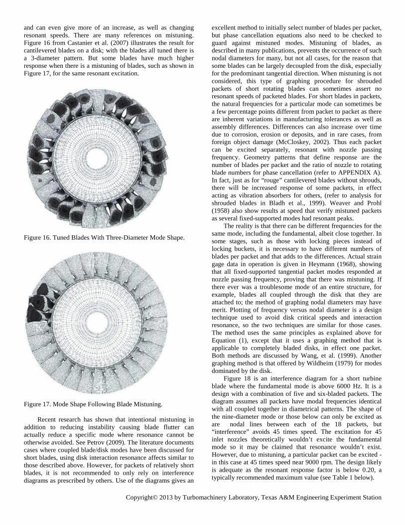
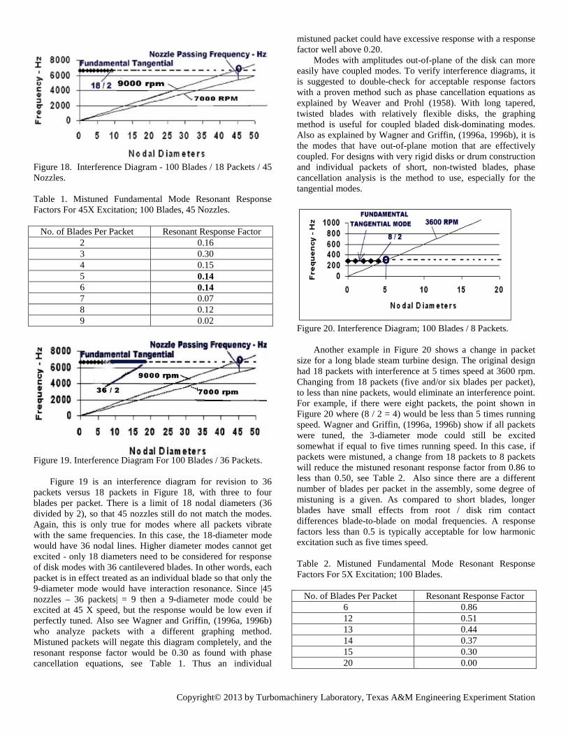
and can even give more of an increase, as well as changing resonant speeds. There are many references on mistuning. Figure 16 from Castanier et al. (2007) illustrates the result for cantilevered blades on a disk; with the blades all tuned there is a 3-diameter pattern. But some blades have much higher response when there is a mistuning of blades, such as shown in Figure 17, for the same resonant excitation.
Figure 16. Tuned Blades With Three-Diameter Mode Shape.
Figure 17. Mode Shape Following Blade Mistuning.
Recent research has shown that intentional mistuning in addition to reducing instability causing blade flutter can actually reduce a specific mode where resonance cannot be otherwise avoided. See Petrov (2009). The literature documents cases where coupled blade/disk modes have been discussed for short blades, using disk interaction resonance affects similar to those described above. However, for packets of relatively short blades, it is not recommended to only rely on interference diagrams as prescribed by others. Use of the diagrams gives an
excellent method to initially select number of blades per packet, but phase cancellation equations also need to be checked to guard against mistuned modes. Mistuning of blades, as described in many publications, prevents the occurrence of such nodal diameters for many, but not all cases, for the reason that some blades can be largely decoupled from the disk, especially for the predominant tangential direction. When mistuning is not considered, this type of graphing procedure for shrouded packets of short rotating blades can sometimes assert no resonant speeds of packeted blades. For short blades in packets, the natural frequencies for a particular mode can sometimes be a few percentage points different from packet to packet as there are inherent variations in manufacturing tolerances as well as assembly differences. Differences can also increase over time due to corrosion, erosion or deposits, and in rare cases, from foreign object damage (McCloskey, 2002). Thus each packet can be excited separately, resonant with nozzle passing frequency. Geometry patterns that define response are the number of blades per packet and the ratio of nozzle to rotating blade numbers for phase cancellation (refer to APPENDIX A). In fact, just as for “rouge” cantilevered blades without shrouds, there will be increased response of some packets, in effect acting as vibration absorbers for others, (refer to analysis for shrouded blades in Bladh et al., 1999). Weaver and Prohl (1958) also show results at speed that verify mistuned packets as several fixed-supported modes had resonant peaks.
The reality is that there can be different frequencies for the same mode, including the fundamental, albeit close together. In some stages, such as those with locking pieces instead of locking buckets, it is necessary to have different numbers of blades per packet and that adds to the differences. Actual strain gage data in operation is given in Heymann (1968), showing that all fixed-supported tangential packet modes responded at nozzle passing frequency, proving that there was mistuning. If there ever was a troublesome mode of an entire structure, for example, blades all coupled through the disk that they are attached to; the method of graphing nodal diameters may have merit. Plotting of frequency versus nodal diameter is a design technique used to avoid disk critical speeds and interaction resonance, so the two techniques are similar for those cases. The method uses the same principles as explained above for Equation (1), except that it uses a graphing method that is applicable to completely bladed disks, in effect one packet. Both methods are discussed by Wang, et al. (1999). Another graphing method is that offered by Wildheim (1979) for modes dominated by the disk.
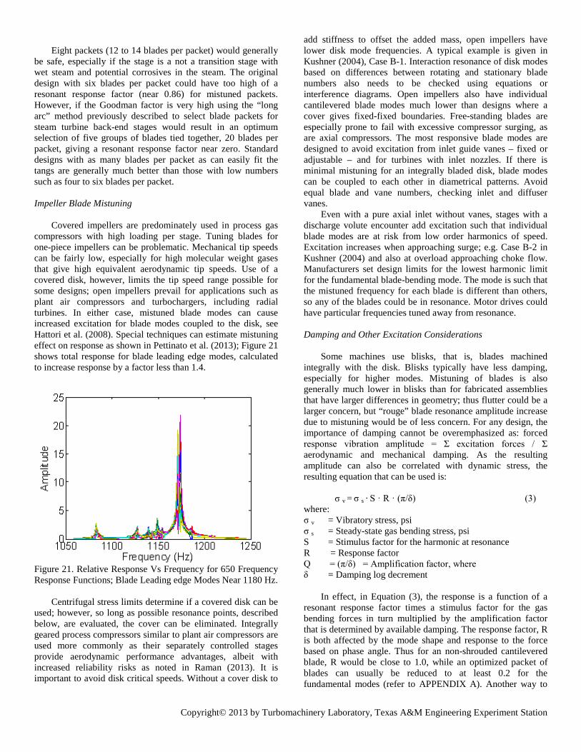
Figure 18 is an interference diagram for a short turbine blade where the fundamental mode is above 6000 Hz. It is a design with a combination of five and six-bladed packets. The diagram assumes all packets have modal frequencies identical with all coupled together in diametrical patterns. The shape of the nine-diameter mode or those below can only be excited as are nodal lines between each of the 18 packets, but “interference” avoids 45 times speed. The excitation for 45 inlet nozzles theoretically wouldn’t excite the fundamental mode so it may be claimed that resonance wouldn’t exist. However, due to mistuning, a particular packet can be excited - in this case at 45 times speed near 9000 rpm. The design likely is adequate as the resonant response factor is below 0.20, a typically recommended maximum value (see Table 1 below).
Copyright© 2013 by Turbomachinery Laboratory, Texas A&M Engineering Experiment Station
Figure 18. Interference Diagram - 100 Blades / 18 Packets / 45 Nozzles. Table 1. Mistuned Fundamental Mode Resonant Response Factors For 45X Excitation; 100 Blades, 45 Nozzles. No. of Blades Per Packet Resonant Response Factor 2 0.16 3 0.30 4 0.15 5 0.14 6 0.14 7 0.07 8 0.12 9 0.02 Figure 19. Interference Diagram For 100 Blades / 36 Packets. Figure 19 is an interference diagram for revision to 36 packets versus 18 packets in Figure 18, with three to four blades per packet. There is a limit of 18 nodal diameters (36 divided by 2), so that 45 nozzles still do not match the modes. Again, this is only true for modes where all packets vibrate with the same frequencies. In this case, the 18-diameter mode would have 36 nodal lines. Higher diameter modes cannot get excited - only 18 diameters need to be considered for response of disk modes with 36 cantilevered blades. In other words, each packet is in effect treated as an individual blade so that only the 9-diameter mode would have interaction resonance. Since |45 nozzles – 36 packets| = 9 then a 9-diameter mode could be excited at 45 X speed, but the response would be low even if perfectly tuned. Also see Wagner and Griffin, (1996a, 1996b) who analyze packets with a different graphing method. Mistuned packets will negate this diagram completely, and the resonant response factor would be 0.30 as found with phase cancellation equations, see Table 1. Thus an individual
mistuned packet could have excessive response with a response factor well above 0.20.
Modes with amplitudes out-of-plane of the disk can more easily have coupled modes. To verify interference diagrams, it is suggested to double-check for acceptable response factors with a proven method such as phase cancellation equations as explained by Weaver and Prohl (1958). With long tapered, twisted blades with relatively flexible disks, the graphing method is useful for coupled bladed disk-dominating modes. Also as explained by Wagner and Griffin, (1996a, 1996b), it is the modes that have out-of-plane motion that are effectively coupled. For designs with very rigid disks or drum construction and individual packets of short, non-twisted blades, phase cancellation analysis is the method to use, especially for the tangential modes.
Figure 20. Interference Diagram; 100 Blades / 8 Packets. Another example in Figure 20 shows a change in packet
size for a long blade steam turbine design. The original design had 18 packets with interference at 5 times speed at 3600 rpm. Changing from 18 packets (five and/or six blades per packet), to less than nine packets, would eliminate an interference point. For example, if there were eight packets, the point shown in Figure 20 where (8 / 2 = 4) would be less than 5 times running speed. Wagner and Griffin, (1996a, 1996b) show if all packets were tuned, the 3-diameter mode could still be excited somewhat if equal to five times running speed. In this case, if packets were mistuned, a change from 18 packets to 8 packets will reduce the mistuned resonant response factor from 0.86 to less than 0.50, see Table 2. Also since there are a different number of blades per packet in the assembly, some degree of mistuning is a given. As compared to short blades, longer blades have small effects from root / disk rim contact differences blade-to-blade on modal frequencies. A response factors less than 0.5 is typically acceptable for low harmonic excitation such as five times speed. Table 2. Mistuned Fundamental Mode Resonant Response Factors For 5X Excitation; 100 Blades. No. of Blades Per Packet Resonant Response Factor 6 0.86 12 0.51 13 0.44 14 0.37 15 0.30 20 0.00
Copyright© 2013 by Turbomachinery Laboratory, Texas A&M Engineering Experiment Station
Eight packets (12 to 14 blades per packet) would generally
be safe, especially if the stage is a not a transition stage with wet steam and potential corrosives in the steam. The original design with six blades per packet could have too high of a resonant response factor (near 0.86) for mistuned packets. However, if the Goodman factor is very high using the “long arc” method previously described to select blade packets for steam turbine back-end stages would result in an optimum selection of five groups of blades tied together, 20 blades per packet, giving a resonant response factor near zero. Standard designs with as many blades per packet as can easily fit the tangs are generally much better than those with low numbers such as four to six blades per packet. Impeller Blade Mistuning
Covered impellers are predominately used in process gas
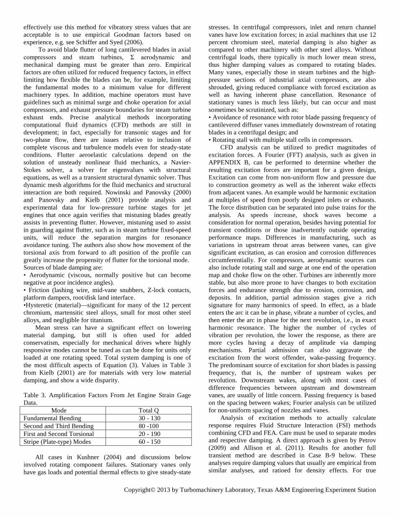
compressors with high loading per stage. Tuning blades for one-piece impellers can be problematic. Mechanical tip speeds can be fairly low, especially for high molecular weight gases that give high equivalent aerodynamic tip speeds. Use of a covered disk, however, limits the tip speed range possible for some designs; open impellers prevail for applications such as plant air compressors and turbochargers, including radial turbines. In either case, mistuned blade modes can cause increased excitation for blade modes coupled to the disk, see Hattori et al. (2008). Special techniques can estimate mistuning effect on response as shown in Pettinato et al. (2013); Figure 21 shows total response for blade leading edge modes, calculated to increase response by a factor less than 1.4.
Figure 21. Relative Response Vs Frequency for 650 Frequency Response Functions; Blade Leading edge Modes Near 1180 Hz.
Centrifugal stress limits determine if a covered disk can be used; however, so long as possible resonance points, described below, are evaluated, the cover can be eliminated. Integrally geared process compressors similar to plant air compressors are used more commonly as their separately controlled stages provide aerodynamic performance advantages, albeit with increased reliability risks as noted in Raman (2013). It is important to avoid disk critical speeds. Without a cover disk to
add stiffness to offset the added mass, open impellers have lower disk mode frequencies. A typical example is given in Kushner (2004), Case B-1. Interaction resonance of disk modes based on differences between rotating and stationary blade numbers also needs to be checked using equations or interference diagrams. Open impellers also have individual cantilevered blade modes much lower than designs where a cover gives fixed-fixed boundaries. Free-standing blades are especially prone to fail with excessive compressor surging, as are axial compressors. The most responsive blade modes are designed to avoid excitation from inlet guide vanes – fixed or adjustable – and for turbines with inlet nozzles. If there is minimal mistuning for an integrally bladed disk, blade modes can be coupled to each other in diametrical patterns. Avoid equal blade and vane numbers, checking inlet and diffuser vanes.
Even with a pure axial inlet without vanes, stages with a discharge volute encounter add excitation such that individual blade modes are at risk from low order harmonics of speed. Excitation increases when approaching surge; e.g. Case B-2 in Kushner (2004) and also at overload approaching choke flow. Manufacturers set design limits for the lowest harmonic limit for the fundamental blade-bending mode. The mode is such that the mistuned frequency for each blade is different than others, so any of the blades could be in resonance. Motor drives could have particular frequencies tuned away from resonance. Damping and Other Excitation Considerations
Some machines use blisks, that is, blades machined
integrally with the disk. Blisks typically have less damping, especially for higher modes. Mistuning of blades is also generally much lower in blisks than for fabricated assemblies that have larger differences in geometry; thus flutter could be a larger concern, but “rouge” blade resonance amplitude increase due to mistuning would be of less concern. For any design, the importance of damping cannot be overemphasized as: forced response vibration amplitude = Σ excitation forces / Σ aerodynamic and mechanical damping. As the resulting amplitude can also be correlated with dynamic stress, the resulting equation that can be used is:
σ v = σ s · S · R · (π/δ) (3) where: σ v = Vibratory stress, psi σ s = Steady-state gas bending stress, psi S = Stimulus factor for the harmonic at resonance R = Response factor Q = (π/δ) = Amplification factor, where δ = Damping log decrement
In effect, in Equation (3), the response is a function of a resonant response factor times a stimulus factor for the gas bending forces in turn multiplied by the amplification factor that is determined by available damping. The response factor, R is both affected by the mode shape and response to the force based on phase angle. Thus for an non-shrouded cantilevered blade, R would be close to 1.0, while an optimized packet of blades can usually be reduced to at least 0.2 for the fundamental modes (refer to APPENDIX A). Another way to
Copyright© 2013 by Turbomachinery Laboratory, Texas A&M Engineering Experiment Station
effectively use this method for vibratory stress values that are acceptable is to use empirical Goodman factors based on experience, e.g. see Schiffer and Syed (2006). To avoid blade flutter of long cantilevered blades in axial compressors and steam turbines, Σ aerodynamic and mechanical damping must be greater than zero. Empirical factors are often utilized for reduced frequency factors, in effect limiting how flexible the blades can be, for example, limiting the fundamental modes to a minimum value for different machinery types. In addition, machine operators must have guidelines such as minimal surge and choke operation for axial compressors, and exhaust pressure boundaries for steam turbine exhaust ends. Precise analytical methods incorporating computational fluid dynamics (CFD) methods are still in development; in fact, especially for transonic stages and for two-phase flow, there are issues relative to inclusion of complete viscous and turbulence models even for steady-state conditions. Flutter aeroelastic calculations depend on the solution of unsteady nonlinear fluid mechanics, a Navier-Stokes solver, a solver for eigenvalues with structural equations, as well as a transient structural dynamic solver. Thus dynamic mesh algorithms for the fluid mechanics and structural interaction are both required. Nowinski and Panovsky (2000) and Panovsky and Kielb (2001) provide analysis and experimental data for low-pressure turbine stages for jet engines that once again verifies that mistuning blades greatly assists in preventing flutter. However, mistuning used to assist in guarding against flutter, such as in steam turbine fixed-speed units, will reduce the separation margins for resonance avoidance tuning. The authors also show how movement of the torsional axis from forward to aft position of the profile can greatly increase the propensity of flutter for the torsional mode. Sources of blade damping are: • Aerodynamic (viscous, normally positive but can become negative at poor incidence angles). • Friction (lashing wire, mid-vane snubbers, Z-lock contacts, platform dampers, root/disk land interface. •Hysteretic (material)—significant for many of the 12 percent chromium, martensitic steel alloys, small for most other steel alloys, and negligible for titanium.
Mean stress can have a significant effect on lowering material damping, but still is often used for added conservatism, especially for mechanical drives where highly responsive modes cannot be tuned as can be done for units only loaded at one rotating speed. Total system damping is one of the most difficult aspects of Equation (3). Values in Table 3 from Kielb (2001) are for materials with very low material damping, and show a wide disparity. Table 3. Amplification Factors From Jet Engine Strain Gage Data. Mode Total Q Fundamental Bending 30 - 130 Second and Third Bending 80 -100 First and Second Torsional 20 - 190 Stripe (Plate-type) Modes 60 - 150
All cases in Kushner (2004) and discussions below
involved rotating component failures. Stationary vanes only have gas loads and potential thermal effects to give steady-state
stresses. In centrifugal compressors, inlet and return channel vanes have low excitation forces; in axial machines that use 12 percent chromium steel, material damping is also higher as compared to other machinery with other steel alloys. Without centrifugal loads, there typically is much lower mean stress, thus higher damping values as compared to rotating blades. Many vanes, especially those in steam turbines and the high-pressure sections of industrial axial compressors, are also shrouded, giving reduced compliance with forced excitation as well as having inherent phase cancellation. Resonance of stationary vanes is much less likely, but can occur and must sometimes be scrutinized, such as: • Avoidance of resonance with rotor blade passing frequency of cantilevered diffuser vanes immediately downstream of rotating blades in a centrifugal design; and • Rotating stall with multiple stall cells in compressors.
CFD analysis can be utilized to predict magnitudes of excitation forces. A Fourier (FFT) analysis, such as given in APPENDIX B, can be performed to determine whether the resulting excitation forces are important for a given design, Excitation can come from non-uniform flow and pressure due to construction geometry as well as the inherent wake effects from adjacent vanes. An example would be harmonic excitation at multiples of speed from poorly designed inlets or exhausts. The force distribution can be separated into pulse trains for the analysis. As speeds increase, shock waves become a consideration for normal operation, besides having potential for transient conditions or those inadvertently outside operating performance maps. Differences in manufacturing, such as variations in upstream throat areas between vanes, can give significant excitation, as can erosion and corrosion differences circumferentially. For compressors, aerodynamic sources can also include rotating stall and surge at one end of the operation map and choke flow on the other. Turbines are inherently more stable, but also more prone to have changes to both excitation forces and endurance strength due to erosion, corrosion, and deposits. In addition, partial admission stages give a rich signature for many harmonics of speed. In effect, as a blade enters the arc it can be in phase, vibrate a number of cycles, and then enter the arc in phase for the next revolution, i.e., in exact harmonic resonance. The higher the number of cycles of vibration per revolution, the lower the response, as there are more cycles having a decay of amplitude via damping mechanisms. Partial admission can also aggravate the excitation from the worst offender, wake-passing frequency. The predominant source of excitation for short blades is passing frequency, that is, the number of upstream wakes per revolution. Downstream wakes, along with most cases of difference frequencies between upstream and downstream vanes, are usually of little concern. Passing frequency is based on the spacing between wakes; Fourier analysis can be utilized for non-uniform spacing of nozzles and vanes.
Analysis of excitation methods to actually calculate response requires Fluid Structure Interaction (FSI) methods combining CFD and FEA. Care must be used to separate modes and respective damping. A direct approach is given by Petrov (2009) and Allison et al. (2011). Results for another full transient method are described in Case B-9 below. These analyses require damping values that usually are empirical from similar analyses, and ratioed for density effects. For true

Copyright© 2013 by Turbomachinery Laboratory, Texas A&M Engineering Experiment Station
damping values, a more complex analysis, such as two-way FSI, is required. Acoustic Excitation and Response
One of the least understood causes of disk vibration is the acoustic interaction with acoustic pressure waves that directly excite the disk. The interaction of pressure waves between disk surfaces and the adjacent stationary wall may also be important, as shown by Eckert (1999) and Ni (1999); the instability of the two-diameter mode from acoustic interaction could also give forced excitation with matching phase angles with the disk modes. Acoustic pressure pulsations rarely reach high enough levels to cause turbomachinery components to fail. For a given sound pressure level such as 150 dB inside a compressor near atmospheric pressure, pulsations traveling at sonic speed are only approximately 0.1 psi (rms). Thus there must also be an associated acoustic mode of the gas to increase excitation, such as can occur with compressor blade passing frequency in attached discharge piping, e.g. Kushner et al. (2002). But there is some confusion because some investigators have said that direct resonance must be avoided where rotating blade passing frequency is equal to a compressor disk mode frequency.
A widely referenced paper by Tyler & Sofrin (1962) provides much insight into jet engine blade passing frequency noise. They showed that tonal noise has inherent number of circumferential lobes based on phase analysis of numbers of rotating blades and stationary vanes. Acoustic pressure waves spin with modal patterns equal to sum and differences of rotating and stationary blade numbers, including harmonics that can also be important.
Jet engine designers must guard against acoustic resonance for cantilevered blades. In addition to acoustic interaction, vortex shedding excites acoustic modes within the annulus that contains axial compressor cantilevered blades. A case of blade failures was analyzed for excitation due to vortex shedding from inlet struts. It was shown not to be the cause, but cracks were initiated by excessive surging of the system with an undersized blowoff valve. (See Case A-2 in Kushner, 2004). However treatment of the inlet vane shapes greatly reduced noise.
Turning now to impellers for centrifugal gas compressors, there is concern that past fatigue failures were excited by acoustic pressure pulsations. Eisinger and Sullivan (2006) described a case due to excessive turbulence at the inlet of a centrifugal fan. Price & Smith (1999) showed that noise caused by an inlet valve was eliminated, as it was the acoustic source for a covered impeller failure, even though it may have been a different mode that what was described. Another source of high noise within machinery is the flow past casing cavities, exciting modes within the cavity, but this would be an extremely rare cause of structural fatigue for rotor components.
Normally, the highest noise source in compressors is found at rotating blade-passing frequency. The wave lengths are typically small enough to have little attenuation as the sound travels up and down piping, thus exciting acoustic modes within the pipes. Resonance can be a concern for piping walls with matching structural modes, but even more importantly has caused cracks at protruding take-offs for instrumentation, etc.
The question under consideration is whether rotating blade
passing frequency noise can actually cause self-excitation of impellers. It appears so, but only in rare cases and most likely in high-pressure compressors where noise levels can be much higher. Richards et al. (2010) utilized strain gauges to confirm disk mode acoustic resonance. This report did not show a resonance at the rotating blade passing frequency, but rather, found that the resonance was due to a combination of upstream vane wakes and downstream vane acoustic reflections. In this case there was no corresponding acoustic resonance of the gas that was coincident with Tyler / Sofrin modes, so it was determined that dynamic strains were not of concern.
Two other recent papers brought the potential of acoustic interaction with impeller structural modes to full understanding with conclusive proof. Petry et al. (2010) confirmed Root Cause Failure Analysis given in the paper by Konig (2009). The two papers give analytical and confirming test results for two actual high-pressure compressor cases where modes of failed impellers were resonant at harmonics of stationary vanes – not at rotating blade-passing frequency. It was shown for 17-bladed impellers there was 5-diameter disk mode with resonance at 22 times speed from downstream vanes, along with side cavity acoustic 5-diameter mode resonance at 17 per rev resonance. The fix for both failure cases was to change number of stationary vanes, from 22 to 25 for Case A and from 22 to 19 for Case B. For both modifications disk modes did not change and blade-passing frequency remained the same, leaving the number of impeller blades at 17.
In the papers it is shown that triple coincidence occurred as needed for significant response: 1. Tyler / Sofrin spinning mode with 5-diameter as 22-17 = 5 2. 5-Diameter disk mode at 22 X speed 3. Acoustic mode of the gas with 5 diameters = 17X In summary, coupling of matching modes, acoustic and structural, is necessary at traveling wave resonance at operating speed. A triple coincidence is needed, the same structural and acoustic mode shape, along with the correct number of stationary vanes to enable Tyler / Sofrin spinning acoustic modes, again with the same shape.
There thus is conclusive proof that rotating blade passing frequency is not a concern if it matches frequency of a disk mode. Rather noise excites at traveling wave frequency, disk diameter mode plus or minus number of diameters times speed. Whenever there is an impeller failure especially for a high-pressure “dry” gas compressor acoustic analysis of gas modes at the sides of the cover and hub disk should be considered especially when the two other factors for “triple coincidence” are met. The acoustic analysis described is similar to the disk interaction resonance equations where phase must be matched. The fluctuating pressure mode shape is a function of the number of rotating blades and the number of stationary vanes. In certain cases there can be a double cause of exciting the same disk mode – acoustic pressure pulsations spinning at blade passing frequency, adding to direct pressure loads due to stationary vanes. The question is answered – high noise at blade passing frequency can rarely cause impellers to fail. Moreover blade-passing frequency is definitely not a concern if it is equal to a disk mode frequency, as long as the number of stationary vanes is a number that does not equal the number of rotating blades, which would be a crucial design error.
Copyright© 2013 by Turbomachinery Laboratory, Texas A&M Engineering Experiment Station
CASE STUDIES
It is important to acknowledge that there is in an optimum outcome to everything and risk taking is necessary to reach that goal. While risk taking is integral to competition, for the customer, the ramifications of a blade or disk failure can be tremendous. Some fairly conservative approaches to blade resonance will be discussed for the various types of machinery to be reviewed. For example, manufacturers have taken more risk by employing many more free-standing blades. In reviewing field problems and field failures for original design and/or machinery operation, the optimum may not always be achieved. A large part of the improvement process is to learn from a limited number of mistakes. These case studies and accompanying references hopefully will assist the reader. A reason for achieving success was given in a January 2004 quotation from Lt. Col. Keith “Sully” Sullivan. Per the director of USA Central Command Joint Search and Rescue Center/Saudi Arabia:”... but sometimes unless you do something wrong, it’s hard to make changes, and we did a lot of things right.” Axial Compressors
Problems with blade resonance for industrial axial compressors should be less than with axial turbines. That is, risk is only less if design and operation minimizes rotating stall, and of course a proper surge control system is used to eliminate heavy repetitive surging. Continuous operation at extremely high flow producing stage choking is also taboo (refer to typical performance map in Gresh, 2001). There are several prime design issues: • Ensure that first stage blades avoid very low harmonic excitation—dictated not only by loading (Goodman factor), but by how well the inlet design minimizes circumferential flow distortion; • Avoid resonance of fundamental modes with upstream vane passing frequency. • Aerodynamic design must be free of rotating stall at all operating points, including those with variable guide vane settings. • Units with variable inlet vanes require accurate spacing; care in preventing ice buildup for some applications is needed to prevent damage to linkage, in turn giving harmonic excitation of rotating blades.
Others have described failures with a poor inlet design that did not include proper straightening vanes, followed by adjustable pre-whirl vanes. Pre-whirl variable guide vanes assist in minimizing non-uniform flow and provide flow equalization as well as the adjustable flow angles required by the first rotating row. Proper operation requires that variable vanes be closed at startup to eliminate rotating stall. A contractor once used stainless steel replacement stationary vanes that failed as they were not 12% chromium with beneficial material damping. By retaining subsonic designs, and generous tip clearances conservatism is ensured; transonic blade designs are much more demanding as relative tip speed increases. Modern units must be designed to avoid blade flutter
of first stage blades, high-pressure blades in choke, and acoustic resonance interaction. These factors are likely reasons why many industrial gas turbine designs changed to 12 percent chromium steel with added material damping, as compared to jet engines that must not surge. Inlet air can contain contaminants, thus coatings may be needed for the front stages.
Using controlled diffusion airfoils (CDA) blades that are actually designed for transonic conditions instead of the old National Advisory Committee for Aeronautics (NACA) recommended circular-arc blades greatly assists in not exceeding vibratory response limits. Improvements by using CDA blades are described by Kilgore (1987). For high flow operation, de-whirl stationary vanes in the discharge casing can be used to guard against cases where process system resistance is such that choking can be within the compressor. Mazzawy (1980) describes some surge data on gas turbine compressors, still and likely always taboo for jet engines. Issues such as measurement of rotating stall are included in Kushner (1996) where there is pressure pulsation data for both surge and stall on a fairly recent axial compressor. In fact the use of dynamic pressure probes eliminated the need for surging at all in setting the surge controls, and verified a proper design without any rotating stall at much lower flows than the surge-control set points over the complete range of vane settings at full speed. (Refer to Kushner (2004) for details of following case studies A-1 and A-2).
Case A-1 (2004)
A case of resonance with upstream vanes causing fatigue of cantilevered blades in an axial flow air blower; the simple solution was to change the number if vanes.
Case A-2 (2004)
A 12-stage axial air compressor with numerous blade and
vane failures due to excessive and continuous surging, caused by improper blow off size and controls. Field verification with strain gages showed that acoustic excitation from vortex shedding was not a cause. Adjustable guide vane and rotating blade strength improvements provided added reliability.
Case A-3
Front-end blades required coating as after extended operation a multi-stage axial compressor had rotating blade corrosion fatigue failures. Although open air inlet filtration was used plant emissions had added corrosive elements to inlet air.
Centrifugal Compressors For the axial compressor Case A-2, the rotor was of drum
construction, so disk modes were a moot point. In many other axial compressors that have disks, disk critical speeds and interaction resonance can be an issue; some lightweight engines have thin disks and must run up and down through disk resonance points. By contrast, industrial centrifugal compressors almost always avoid disk critical speeds, especially for stages with 90-degree inlets and / or volutes. (Refer to Kushner (2004) for more details of following case
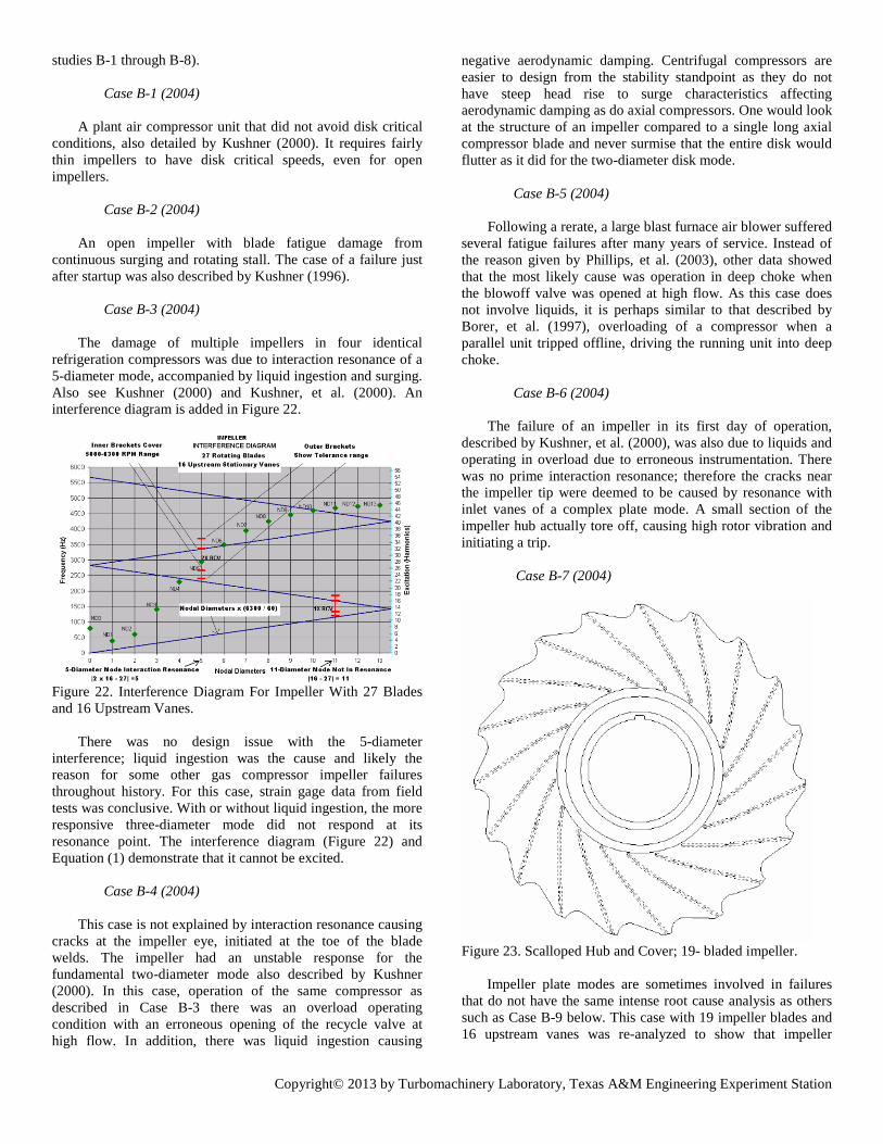
Copyright© 2013 by Turbomachinery Laboratory, Texas A&M Engineering Experiment Station
studies B-1 through B-8).
Case B-1 (2004)
A plant air compressor unit that did not avoid disk critical conditions, also detailed by Kushner (2000). It requires fairly thin impellers to have disk critical speeds, even for open impellers.
Case B-2 (2004)
An open impeller with blade fatigue damage from
continuous surging and rotating stall. The case of a failure just after startup was also described by Kushner (1996).
Case B-3 (2004)
The damage of multiple impellers in four identical
refrigeration compressors was due to interaction resonance of a 5-diameter mode, accompanied by liquid ingestion and surging. Also see Kushner (2000) and Kushner, et al. (2000). An interference diagram is added in Figure 22.
Figure 22. Interference Diagram For Impeller With 27 Blades and 16 Upstream Vanes.
There was no design issue with the 5-diameter interference; liquid ingestion was the cause and likely the reason for some other gas compressor impeller failures throughout history. For this case, strain gage data from field tests was conclusive. With or without liquid ingestion, the more responsive three-diameter mode did not respond at its resonance point. The interference diagram (Figure 22) and Equation (1) demonstrate that it cannot be excited.
Case B-4 (2004)
This case is not explained by interaction resonance causing cracks at the impeller eye, initiated at the toe of the blade welds. The impeller had an unstable response for the fundamental two-diameter mode also described by Kushner (2000). In this case, operation of the same compressor as described in Case B-3 there was an overload operating condition with an erroneous opening of the recycle valve at high flow. In addition, there was liquid ingestion causing
negative aerodynamic damping. Centrifugal compressors are easier to design from the stability standpoint as they do not have steep head rise to surge characteristics affecting aerodynamic damping as do axial compressors. One would look at the structure of an impeller compared to a single long axial compressor blade and never surmise that the entire disk would flutter as it did for the two-diameter disk mode.
Case B-5 (2004)
Following a rerate, a large blast furnace air blower suffered
several fatigue failures after many years of service. Instead of the reason given by Phillips, et al. (2003), other data showed that the most likely cause was operation in deep choke when the blowoff valve was opened at high flow. As this case does not involve liquids, it is perhaps similar to that described by Borer, et al. (1997), overloading of a compressor when a parallel unit tripped offline, driving the running unit into deep choke.
Case B-6 (2004)
The failure of an impeller in its first day of operation,
described by Kushner, et al. (2000), was also due to liquids and operating in overload due to erroneous instrumentation. There was no prime interaction resonance; therefore the cracks near the impeller tip were deemed to be caused by resonance with inlet vanes of a complex plate mode. A small section of the impeller hub actually tore off, causing high rotor vibration and initiating a trip.
Case B-7 (2004)
Figure 23. Scalloped Hub and Cover; 19- bladed impeller. Impeller plate modes are sometimes involved in failures that do not have the same intense root cause analysis as others such as Case B-9 below. This case with 19 impeller blades and 16 upstream vanes was re-analyzed to show that impeller
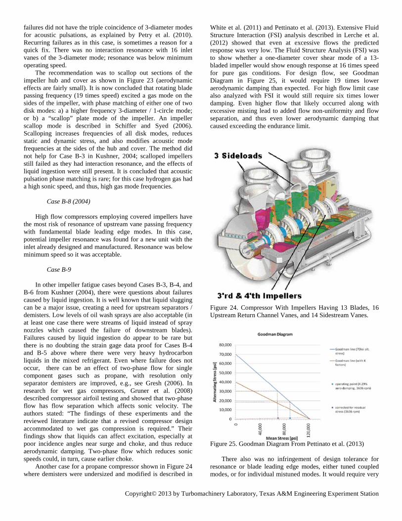
Copyright© 2013 by Turbomachinery Laboratory, Texas A&M Engineering Experiment Station
failures did not have the triple coincidence of 3-diameter modes for acoustic pulsations, as explained by Petry et al. (2010). Recurring failures as in this case, is sometimes a reason for a quick fix. There was no interaction resonance with 16 inlet vanes of the 3-diameter mode; resonance was below minimum operating speed. The recommendation was to scallop out sections of the impeller hub and cover as shown in Figure 23 (aerodynamic effects are fairly small). It is now concluded that rotating blade passing frequency (19 times speed) excited a gas mode on the sides of the impeller, with phase matching of either one of two disk modes: a) a higher frequency 3-diameter / 1-circle mode; or b) a “scallop” plate mode of the impeller. An impeller scallop mode is described in Schiffer and Syed (2006). Scalloping increases frequencies of all disk modes, reduces static and dynamic stress, and also modifies acoustic mode frequencies at the sides of the hub and cover. The method did not help for Case B-3 in Kushner, 2004; scalloped impellers still failed as they had interaction resonance, and the effects of liquid ingestion were still present. It is concluded that acoustic pulsation phase matching is rare; for this case hydrogen gas had a high sonic speed, and thus, high gas mode frequencies. Case B-8 (2004) High flow compressors employing covered impellers have the most risk of resonance of upstream vane passing frequency with fundamental blade leading edge modes. In this case, potential impeller resonance was found for a new unit with the inlet already designed and manufactured. Resonance was below minimum speed so it was acceptable. Case B-9 In other impeller fatigue cases beyond Cases B-3, B-4, and B-6 from Kushner (2004), there were questions about failures caused by liquid ingestion. It is well known that liquid slugging can be a major issue, creating a need for upstream separators / demisters. Low levels of oil wash sprays are also acceptable (in at least one case there were streams of liquid instead of spray nozzles which caused the failure of downstream blades). Failures caused by liquid ingestion do appear to be rare but there is no doubting the strain gage data proof for Cases B-4 and B-5 above where there were very heavy hydrocarbon liquids in the mixed refrigerant. Even where failure does not occur, there can be an effect of two-phase flow for single component gases such as propane, with resolution only separator demisters are improved, e.g., see Gresh (2006). In research for wet gas compressors, Gruner et al. (2008) described compressor airfoil testing and showed that two-phase flow has flow separation which affects sonic velocity. The authors stated: “The findings of these experiments and the reviewed literature indicate that a revised compressor design accommodated to wet gas compression is required.” Their findings show that liquids can affect excitation, especially at poor incidence angles near surge and choke, and thus reduce aerodynamic damping. Two-phase flow which reduces sonic speeds could, in turn, cause earlier choke. Another case for a propane compressor shown in Figure 24 where demisters were undersized and modified is described in
White et al. (2011) and Pettinato et al. (2013). Extensive Fluid Structure Interaction (FSI) analysis described in Lerche et al. (2012) showed that even at excessive flows the predicted response was very low. The Fluid Structure Analysis (FSI) was to show whether a one-diameter cover shear mode of a 13-bladed impeller would show enough response at 16 times speed for pure gas conditions. For design flow, see Goodman Diagram in Figure 25, it would require 19 times lower aerodynamic damping than expected. For high flow limit case also analyzed with FSI it would still require six times lower damping. Even higher flow that likely occurred along with excessive misting lead to added flow non-uniformity and flow separation, and thus even lower aerodynamic damping that caused exceeding the endurance limit.
Figure 24. Compressor With Impellers Having 13 Blades, 16 Upstream Return Channel Vanes, and 14 Sidestream Vanes. Figure 25. Goodman Diagram From Pettinato et al. (2013) There also was no infringement of design tolerance for resonance or blade leading edge modes, either tuned coupled modes, or for individual mistuned modes. It would require very

Copyright© 2013 by Turbomachinery Laboratory, Texas A&M Engineering Experiment Station
high flow and liquid ingestion greatly reducing aerodynamic damping to initiate cracks at the blade leading edges. Crack initiation sites were at locations where there were not any weld defects. The FSI results confirmed that HCF would be at the blade leading edge at the toe of the weld where centrifugal stress was also at the maximum. For the redesigned impeller the shot-peened weld was moved to the hub side, with a generous fillet radius at the cover side. In addition a more recent material, 13 chromium - 4 nickel alloy with higher toughness, weld-ability and through-hardness was used. With the new weld location employing a “T-head” design shown in Figure 26, blades had higher fundamental leading edge mode frequencies, even further from resonance with upstream vane wakes. Figure 26. Revised Impeller With T-Head Welds Giving Higher Margin For Blade Mode Resonance. Figure 27. Original (Left) And Revised Sideload Designs. All three upstream sideloads were improved to reduce non-uniform flow excitation due to 90-degree casing entries (Figure 27). Along with sideload demister improvements to reduce misting the third and fourth stage impellers were improved to have even more margin from resonance of both disk and blade modes, using the same impeller blade and return channel vane numbers. Limits in operation were placed to be sure there was not infringement past maximum allowable flow. Rotor inspection during a 2013 planned plant turnaround after two years operation verified the redesign was successful.
Turbines
Radial-inflow turbines with non-shrouded impellers have similar excitation concerns as compressors, but inlet vane excitation can cause higher disk mode excitation due to their location near the compliant impeller tip. For steam turbines, as related in a lecture by the expert Den Hartog (1954), a golden rule for cantilevered long blades is never to allow the fundamental mode to equal two per rev, especially for turbine generator sets prone to severe electrical impulses. Catastrophic failures due to transient torsional excitation at twice line frequency have occurred; in effect the torsional vibration of the entire rotor is exciting the base of the blades. Other engineering standards for long blades (and others) are made by a myriad of individual vendors with many designs, shrouding, and friction damping methods (refer for example to Sohre, 1975). Fixed-speed turbines can have accurate tuning to avoid the important resonant modes. Most designs still use 12 percent chromium steel, as there is some benefit from hysteretic damping, although steady-state (mean) stress reduces values as shown in Kushner (2004).
Some designs are highly scrutinized so that materials such as titanium and other variations of corrosion-resistant stainless steels can be used in a specific design or modification for a problem such as those in the transition zone experiencing corrosion fatigue. The risk can be higher for some variables, however, so that care must be used; for example, avoiding flutter conditions where material damping adds to the positive side of the equation. There have been some recent examples where blade lives have “only” been 20 years for some long back-end blades employing Zig-Zag damping pins (shown in Figure 3 above). Non-uniformity of upstream nozzles can increase with time, in turn, increasing forces at low harmonics of speed. In some cases, the most economical solution would be to add more conservatism by employing Z-lock shrouds or integral shrouds with rolled-in lashing wire. (Refer to Kushner (2004) for more details of following case studies C-1 through C-4). Case C-1 (2004)
A turbine with reduced endurance strength in the transition zone suffered a failure, with an axial mode having first order resonance with special inlet nozzle vanes used to add rigidity to the diaphragm. Both “stress corrosion” and “corrosion fatigue” can become a contentious issue for steam turbines whenever there is a field failure for a stage in the transition zone. These types of incidents are likely the reason the API 612 committee had an extreme specification for the Fifth Edition with respect to resonance. The higher modes with phase changes along the blade are safe, even with resonance, as response is negligible. The Sixth edition of API (2005) shows acceptable stresses that were omitted in the Fifth Edition. It is known that corrosion fatigue is a special type of stress corrosion caused by the combined effects of cyclic stress and corrosion (refer to McCloskey, 2002). Turbine metals are not immune to some reduction of resistance to cyclic stressing if the metal is in a corrosive environment. By far, the highest propensity is where the water droplets first form, at the
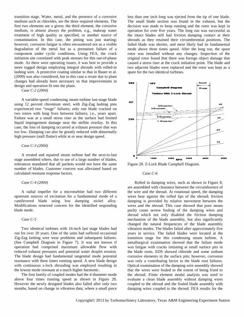
Copyright© 2013 by Turbomachinery Laboratory, Texas A&M Engineering Experiment Station
transition stage. Water, metal, and the presence of a corrosive medium such as chlorides, are the three required elements. The first two elements are a given; the third element, the corrosive medium, is almost always the problem, e.g., makeup water treatment of high quality as specified, or another source of contamination. In this case, the pitting was just starting; however, corrosion fatigue is often encountered not as a visible degradation of the metal but as a premature failure of a component under cyclic conditions. Using FEA, the crack initiation site correlated with peak stresses for this out-of-phase mode. As there were operating issues, it was best to provide a more rugged design employing integral shrouds with rolled-in lashing wire. A protective coating similar to that in Bauer et al. (2009) was also considered, but in this case a rerate due to plant changes had already been necessary so that improvements in design and operation fit into the plans. Case C-2 (2004) A variable-speed condensing steam turbine last-stage blade using 12 percent chromium steel, with Zig-Zag lashing pins experienced two “rouge” failures; only one blade cracked on two rotors with long lives between failures, i.e., years apart. Failure was at a small stress riser as the surface had limited liquid impingement damage near the stellite overlay. In this case, the loss of damping occurred at exhaust pressure that was too low. Damping can also be greatly reduced with abnormally high pressure (stall flutter) while at or near design speed. Case C-3 (2004) A rerated and repaired steam turbine had the next-to-last stage assembled where, due to use of a large number of blades, tolerances mandated that all packets would not have the same number of blades. Customer concern was alleviated based on calculated resonant response factors. Case C-4 (2004) A radial impeller for a microturbine had two different upstream sources of excitation for a fundamental mode of a cantilevered blade using low damping nickel alloy. Modifications removed concern for the identified responding blade mode. Case C-5 Two identical turbines with 16-inch last stage blades had run for over 20 years. One of the units had suffered occasional Zig-Zag lashing wire wear problems and subsequent failures. (See Campbell Diagram in Figure 7). It was not known if operation had comprised maximum allowable flow with reduced exhaust pressures and potential water droplet erosion. The blade design had fundamental tangential mode potential resonance with three times running speed. A new blade design with continuous z-lock shrouding was employed resulting in the lowest mode resonant at a much higher harmonic. The first family of coupled modes had the 4-diameter mode above four times running speed as shown in Figure 28. However the newly designed blades also failed after only two months, based on change in vibration data, where a small piece
less than one inch long was ejected from the tip of one blade. The small blade section was found in the exhaust, but the decision was made to keep running and the rotor was kept in operation for over five years. The long run was successful as the intact blades still had friction damping contact at their shrouds as they retained their circumferential positions. The failed blade was shorter, and most likely had its fundamental mode above three times speed. After the long run, the spare rotor was installed without any changes. Inspection of the original rotor found that there was foreign object damage that caused a stress riser at the crack initiation point. The blade and two adjacent blades were replaced and the rotor was kept as a spare for the two identical turbines. Figure 28. Z-Lock Blade Campbell Diagram. Case C-6 Rolled in damping wires, such as shown in Figure 8, are assembled with clearance between the circumference of the wire and the shroud. At rotational speed, the damping wires bear against the rolled lips of the shroud; friction damping is provided by relative movement between the wires and the shroud. This case showed that poor steam purity cause severe fouling of the damping wires and shroud which not only disabled the friction damping mechanism of the blade assembly, but also significantly changed the natural frequencies of the blade assembly vibration modes. The blades failed after approximately five years in service. The failed blades were located at the transition stage for this condensing steam turbine. A metallurgical examination showed that the failure mode was fatigue with cracks initiating at small surface pits in the blade roots. EDS showed chloride and some sodium corrosive elements in the surface pits; however, corrosion was only a contributing factor in the blade root failures. Optical examination of the damping wire assembly showed that the wires were fouled to the extent of being fixed to the shroud. Finite element modal analysis was used to evaluate a clean blade assembly without damping wires coupled to the shroud and the fouled blade assembly with damping wires coupled to the shroud. FEA results for the
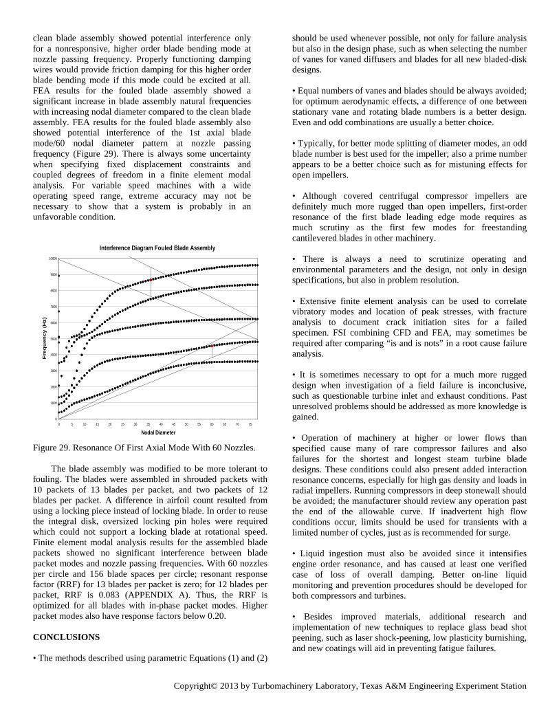
Copyright© 2013 by Turbomachinery Laboratory, Texas A&M Engineering Experiment Station
clean blade assembly showed potential interference only for a nonresponsive, higher order blade bending mode at nozzle passing frequency. Properly functioning damping wires would provide friction damping for this higher order blade bending mode if this mode could be excited at all. FEA results for the fouled blade assembly showed a significant increase in blade assembly natural frequencies with increasing nodal diameter compared to the clean blade assembly. FEA results for the fouled blade assembly also showed potential interference of the 1st axial blade mode/60 nodal diameter pattern at nozzle passing frequency (Figure 29). There is always some uncertainty when specifying fixed displacement constraints and coupled degrees of freedom in a finite element modal analysis. For variable speed machines with a wide operating speed range, extreme accuracy may not be necessary to show that a system is probably in an unfavorable condition.
Interference Diagram Fouled Blade Assembly
0
1000
2000
3000
4000
5000
6000
7000
8000
9000
10000
0 5 10 15 20 25 30 35 40 45 50 55 60 65 70 75
Nodal Diameter
Fre
qu
ency
(H
z)
Figure 29. Resonance Of First Axial Mode With 60 Nozzles. The blade assembly was modified to be more tolerant to fouling. The blades were assembled in shrouded packets with 10 packets of 13 blades per packet, and two packets of 12 blades per packet. A difference in airfoil count resulted from using a locking piece instead of locking blade. In order to reuse the integral disk, oversized locking pin holes were required which could not support a locking blade at rotational speed. Finite element modal analysis results for the assembled blade packets showed no significant interference between blade packet modes and nozzle passing frequencies. With 60 nozzles per circle and 156 blade spaces per circle; resonant response factor (RRF) for 13 blades per packet is zero; for 12 blades per packet, RRF is 0.083 (APPENDIX A). Thus, the RRF is optimized for all blades with in-phase packet modes. Higher packet modes also have response factors below 0.20. CONCLUSIONS • The methods described using parametric Equations (1) and (2)
should be used whenever possible, not only for failure analysis but also in the design phase, such as when selecting the number of vanes for vaned diffusers and blades for all new bladed-disk designs. • Equal numbers of vanes and blades should be always avoided; for optimum aerodynamic effects, a difference of one between stationary vane and rotating blade numbers is a better design. Even and odd combinations are usually a better choice. • Typically, for better mode splitting of diameter modes, an odd blade number is best used for the impeller; also a prime number appears to be a better choice such as for mistuning effects for open impellers. • Although covered centrifugal compressor impellers are definitely much more rugged than open impellers, first-order resonance of the first blade leading edge mode requires as much scrutiny as the first few modes for freestanding cantilevered blades in other machinery. • There is always a need to scrutinize operating and environmental parameters and the design, not only in design specifications, but also in problem resolution. • Extensive finite element analysis can be used to correlate vibratory modes and location of peak stresses, with fracture analysis to document crack initiation sites for a failed specimen. FSI combining CFD and FEA, may sometimes be required after comparing “is and is nots” in a root cause failure analysis. • It is sometimes necessary to opt for a much more rugged design when investigation of a field failure is inconclusive, such as questionable turbine inlet and exhaust conditions. Past unresolved problems should be addressed as more knowledge is gained. • Operation of machinery at higher or lower flows than specified cause many of rare compressor failures and also failures for the shortest and longest steam turbine blade designs. These conditions could also present added interaction resonance concerns, especially for high gas density and loads in radial impellers. Running compressors in deep stonewall should be avoided; the manufacturer should review any operation past the end of the allowable curve. If inadvertent high flow conditions occur, limits should be used for transients with a limited number of cycles, just as is recommended for surge. • Liquid ingestion must also be avoided since it intensifies engine order resonance, and has caused at least one verified case of loss of overall damping. Better on-line liquid monitoring and prevention procedures should be developed for both compressors and turbines. • Besides improved materials, additional research and implementation of new techniques to replace glass bead shot peening, such as laser shock-peening, low plasticity burnishing, and new coatings will aid in preventing fatigue failures.
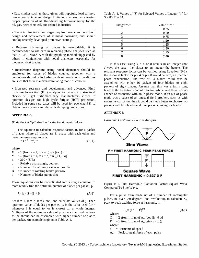
Copyright© 2013 by Turbomachinery Laboratory, Texas A&M Engineering Experiment Station
• Case studies such as those given will hopefully lead to more prevention of inherent design limitations, as well as ensuring proper operation of all fluid-handling turbomachinery for the oil, gas, petrochemical, and related industries. • Steam turbine transition stages require more attention in both design and achievement of minimal corrosion, and should employ recently developed protective coatings. • Because mistuning of blades is unavoidable, it is recommended to use care in replacing phase analyses such as that in APPENDIX A with the graphing method suggested by others in conjunction with nodal diameters, especially for modes of short blades. • Interference diagrams using nodal diameters should be employed for cases of blades coupled together with a continuous shroud or locked-up with z-shrouds, or if conditions are such that there is a disk-dominating mode of concern. • Increased research and development and advanced Fluid Structure Interaction (FSI) analyses and acoustic / structural checks will get turbomachinery manufacturers closer to optimum designs for high cycle fatigue (HCF) protection. Included in some rare cases will be need for two-way FSI to obtain more accurate aerodynamic damping predictions. APPENDIX A Blade Packet Optimization for the Fundamental Mode
The equation to calculate response factor, R, for a packet
of blades where all blades are in phase with each other and have the same amplitude is:
R = (X2 + Y2)1/2 (A-1) where: X = Σ (from i = 1, to i = p) cos [(i-1) · α] Y = Σ (from i = 1, to i = p) sin [(i-1) · α] α = 360 · (S/B) α = Relative phase angle, degrees S = Number of stationary vanes or nozzles B = Number of rotating blades per row p = Number of blades per packet
These equations can be consolidated into a single equation to more readily find the optimum number of blades per packet, p:
J = k · |S – B| / B (A-2) Set k = 1, k = 2, k =3, etc., and calculate values of j. Then optimum value of blades per packet, p, is the value used for k whenever j is equal to, or is closest to, a whole integer. Multiples of the optimum value of p can also be used, as long as the shroud can be assembled with higher number of blades per packet. An example is given in Table A-1.
Table A -1. Values of “J” for Selected Values of Integer “k” for S = 80, B = 64. Integer “k” Value of “j” 1 0.25 2 0.50 3 0.75 4 1.00 5 1.25 6 1.50 7 1.75 8 2.00 In this case, using k = 4 or 8 results in an integer (not always the case—the closer to an integer the better). The resonant response factor can be verified using Equation (B-1), the response factor for p = 4 or p = 8 would be zero, i.e., perfect phase cancellation. The row of 64 blades could thus be assembled with either 16 packets of four blades, or eight packets of eight blades. Assume that this was a fairly long blade at the transition zone of a steam turbine, and there was no chance of resonance with an in-phase mode. If an out-of-phase mode was a cause of an unusual field problem, such as with excessive corrosion, then it could be much better to choose two packets with five blades and nine packets having six blades. APPENDIX B
Harmonic Excitation - Fourier Analysis a
Figure B-1. First Harmonic Excitation Factor: Square Wave Compared To Sine Wave.
For a pulse train made up of a number of rectangular pulses, m, over 360 degrees (one revolution), to calculate Sh, peak-to-peak exciting force at harmonic, h:
Sh = (C2 + D2)1/2 (B-1) where: C = Σ from 1 to m of Am [cos (h · θm)] D = Σ from 1 to m of Am [sin (h · θm)] where: h = Harmonic of speed Am = Peak-to-peak force of each pulse
Copyright© 2013 by Turbomachinery Laboratory, Texas A&M Engineering Experiment Station
βm = Angle from zero degrees to center of each pulse and: Am = am [2 / (h / π)] · sin (h · βm / 2) (B-2) where: am = Fraction of maximum force of any pulse βm = Rectangular width of pulse, degrees.
For a sine wave, shown in Figure B-1, at resonance, the
exciting force is in-phase with the response over the entire vibration cycle. As the force is out-of-phase over part of the cycle, a square wave for example would only have 0.637 times the exciting force of a sine wave at the first harmonic. For the square wave, a rectangular pulse with β = 180 degrees, Equation (C-1) simplifies to:
Sh = | [2 / (h / π)] · sin (h · 180/2)| (B-3)
First harmonic, S1 = |2 / π · sin (90)| = 0.637 Second, S2 = |2 / 2π · sin (180)| = 0.0 Third, S3 = |2 / 3π · sin (270)| = 0.212 Fourth, etc. REFERENCES Allison, T., Lerche, A., Moore, J.J., “Experimental Validation
of Empirical Methods for Dynamic Stress Prediction in Turbomachinery Blades,” Proceedings of ASME Turbo Expo Paper GT2011-45901: Power for Land, Sea and Air: Vancouver, British Columbia, Canada. June 6-10, 2011
API 612, 2005, (ISO 10437) “Petroleum, Petrochemical and
Natural gas Industries – Steam Turbines - Special-Purpose Applications,” Sixth Edition, American Petroleum Institute, Washington, D.C.
Baade, P. K., 1998, “Vibration Control of Propeller Fans,”
Sound and Vibration, July, pp. 16-26. Bauer, D., Tadeu, D., Morais, S., 2009, “Application of
Corrosion Resistant / Antifoulant Coating on Latter - Stage Steam Turbine Blades,” Case Study, 38thTurbomachinery Symposium, Turbomachinery Laboratory, Texas A&M University, College Station, TX.
Bhaduri, A. K., Albert, S. K., Ray, S. K., and Rodriguez, P.,
2003, “Recent Trends in Repair and Refurbishing of Steam Turbine Components,” Sadhana (India), 28, Parts 3 & 4, June/August, pp. 395–408.
Bladh, R., Castanier, M. P., and Pierre, C., 1999, “Reduced
Order Modeling and Vibration Analysis of Mistuned Bladed Disk Assemblies with Shrouds,” ASME Journal of Engineering for Gas Turbines and Power, 121, (3), pp. 515-522.
Bladh, J. R., 2001, “Efficient Predictions Of The Vibratory
Response Of Mistuned Bladed Disks By Reduced Order Modeling,” PhD Dissertation, University of Michigan, Ann Arbor, Michigan, USA.
Bladh, R., Pierre, C., Castanier, M. P., and Kruse, M. J., 2002, “Dynamic Response Predictions for a Mistuned Industrial Turbomachinery Rotor Using Reduced-Order Modeling,” Journal of Engineering for Gas Turbines and Power, 124, pp. 311-324.
Borer, C., Sorokes, J. M., McMahon, T., and Abraham, E. A.,
1997, “An Assessment of the Forces Acting upon a Centrifugal Impeller Using Full Load, Full Pressure Hydrocarbon Testing,” Proceedings of the Twenty-Sixth Turbomachinery Symposium, Turbomachinery Laboratory, Texas A&M University, College Station, Texas, pp. 111-121.
Bultzo, C., 1975, “Analysis of Three Impeller Failures:
Experimental Techniques Used to Establish Causes,” Proceedings of the Fourth Turbomachinery Symposium, Turbomachinery Laboratory, Texas A&M University, College Station, Texas, pp. 31-38.
Campbell, W., 1924, “The Protection of Steam Turbine Disc
Wheels from Axial Vibration,” Transactions of the ASME, 46, pp. 31-160.
Castanier, M. P., Ceccio S. L., Epureanu, B, I., Pierre, C,
(2007) “Next-Generation Modeling, Analysis, and Testing of the Vibration of Mistuned Bladed Disks,” AFOSR Grant FA9550-04-1-0099, The University of Michigan, Ann Arbor, MI, USA.
Clark, E.E., 1996, “Rotating Equipment Loss prevention – An
Insurer’s Viewpoint,” Proceedings of the 25th Turbomachinery Symposium, Turbomachinery Laboratory, Texas A&M University, College Station, TX.
Den Hartog, J. P., 1954, Mechanical Vibrations, New York,
New York: McGraw-Hill, Book Available From Dover Publications, Mineola, New York.
Dowson, P., Rishel, D. M., and Bornstein, N. S., 1995, “Factors
and Preventive Measures Relative to the High Temperature Corrosion of Blade/Disk Components in FCC Power Recovery Turbines,” Proceedings of the Twenty-Fourth Turbomachinery Symposium, Turbomachinery Laboratory, Texas A&M University, College Station, Texas, pp. 11-26.
Eckert, L., 1999, “High Cycle Fatigue Cracks at Radial Fan
Impellers Caused by Aeroelastic Self-Excited Impeller Vibrations, Part 1: Case History, Root Cause Analysis, Vibration Measurements,” Proceedings of DETC99, 1999 ASME Design Engineering Technical Conference, DETC99/VIB-8261.
Eisinger F.L., Sullivan R. E., 2006 “Vibration Fatigue of
Centrifugal Fan Impeller Due to Structural-Acoustic Coupling and Its Prevention: A Case Study,” PVP2006-ICPVT-11-93049; pp. 47-53 ASME Proceedings - 2006 Pressure Vessels and Piping/ICPVT-11.
Ewins, D. J., 1973, “Vibration Characteristics of Bladed Disc
Copyright© 2013 by Turbomachinery Laboratory, Texas A&M Engineering Experiment Station
Assemblies,” Journal of Mechanical Engineering Science, 15, (3), pp. 165-186.
Gruner, T. J., Bakken, L. E., Brenne, L., Bjørge, T., “An
Experimental Investigation of Airfoil Performance in Wet Gas Flow,” Proceedings of ASME Turbo Expo 2008: Power for Land, Sea and Air, GT2008-50483.
Gresh, M. T., 2001, "Compressor Performance: Aerodynamics
for the User," Woburn, Massachusetts: Butterworth Heinemann, p. 42.
Gresh, M. T., 2006 “Avoid refrigeration compressor damage,”
Hydrocarbon Processing Magazine, October, 2006, pp 93-94.
Hattori, H., Unno, M., Hayashi, M., 2008, “Mistuned Vibration
of Radial Inflow Turbine Impeller,” Journal of Fluid Science and Technology, Vol. 3, No. 6, pp. 764-774.
Heymann, F. J., 1968, “Turbine Blade Vibration Due to Nozzle
Wakes,” ASME Paper No. 6SWA/Pwr-1. International Association of Engineering Insurers (IMIA),
2005, “Maintenance and Overhaul of Steam Turbines,” 38th Annual Conference – Moscow 2005.
Jay, R. L., MacBain, J. C., and Burns, D.W., 1983, “Structural
Response Due to Blade Vane Interaction,” ASME Paper 83-GT-133.
Kielb, R. E., 2001, Short Course on Blade Vibration, Presented
at the Elliott Company, February 2001. Kilgore, T. H., 1987, “Adapting State-of-the-Art Turbojet
Aerodynamic Design Techniques to Industrial Axial Compressors,” Proceedings of the Institute of Mechanical Engineers, C121/87, pp. 117-122.
Kohnke, P., 1999, “Modal Analysis of Cyclic Symmetric
Structures,” ANSYS: Theory Reference, Release 5.6, Eleventh Edition, ANSYS, Inc., Canonsburg, Pennsylvania, pp. 15-68 to 15-70.
Konig, S., Petry, N., Wagner, N.G., 2009, “Aeroacoustic
Phenomenon in High-Pressure Centrifugal Compressors - A Possible Root Cause For Impeller Failures,” Proceedings of the 38th Turbomachinery Symposium, Turbomachinery Laboratory, Texas A&M University, College Station, TX.
Kushner, F., 1979, “Disc Vibration - Rotating Blade and
Stationary Vane Interaction,” ASME Paper No. 79-Det-83: ASME Transactions, Journal of Mechanical Design, 102, pp. 579-584.
Kushner, F., 1996, “Dynamic Data Analysis of Compressor
Rotating Stall,” Proceedings of the Twenty-Fifth Turbomachinery Symposium, Turbomachinery Laboratory, Texas A&M University, College Station, Texas, pp. 71-81.
Kushner, F., 2000, “Compressor Blade and Impeller Rotating Disk Vibration Avoidance Parameters,” Proceedings of the ASME Conference: Challenges and Goals in Industrial and Pipeline Compressors, Orlando, Florida, November, PID-5, pp. 81-89.
Kushner, F., Richard, S. J., and Strickland R. A., 2000,
“Critical Review of Compressor Impeller Vibration Parameters for Failure Prevention,” Proceedings of the Twenty-Ninth Turbomachinery Symposium, Turbomachinery Laboratory, Texas A&M University, College Station, Texas, pp. 103-112.
Kushner, F., Walker, D., and Hohlweg, W. C., 2002,
“Compressor Discharge Pipe Failure Investigation with a Review of Surge, Rotating Stall, and Piping Resonance,” Proceedings of the Thirty-First Turbomachinery Symposium, Turbomachinery Laboratory, Texas A&M University, College Station, Texas, pp. 49-60.
Kushner, F., 2004, "Rotating Component Modal Analysis and
Resonance Avoidance Recommendations," Tutorial, Proceedings of the 33rd Turbomachinery Symposium, Turbomachinery Laboratory, Texas A&M University, College Station, TX.
Layton, R. A. and Marra, J. J., 2000, “Conceptual Basis for a
New Approach to Bladed-Disk Design,” Journal of Engineering for Gas Turbines and Power, 122, pp. 321-325.
Lerche, A. H., Moore, J. J., Hardin, J., White, N. M., (2012),
“Dynamic Stress Prediction in Centrifugal Compressor Blades Using Fluid Structure Interaction,” Proceedings of ASME Turbo Expo 2012, GT2012-69933.
Mazzawy, R. S., 1980, “Surge-Induced Structural Loads in Gas
Turbines,” ASME Journal of Engineering for Power, 102, pp. 162-168.
McCloskey, T. H., 2002, “Troubleshooting Turbine Steam Path
Damage Mechanisms,” Proceedings of the Thirty-First Turbomachinery Symposium, Turbomachinery Laboratory, Texas A&M University, College Station, Texas, pp. 105-143.
NASA, 1990, “Fourier Analysis of Vibrations of Round
Structures,” Marshall Space Flight Center, NASA Tech Brief MFS-29334-1, Vol. 14, p 74.
Ni, A., 1999, “High Cycle Fatigue Cracks at Radial Fan
Impellers Caused by Aeroelastic Self-Excited Impeller Vibrations, Part 2: Mechanism and Mathematical Model,” Proceedings of DETC99, 1999 ASME Design Engineering Technical Conference, DETC99/VIB-8262.
Nowinski, M. and Panovsky, J., 2000, “Flutter Mechanisms in
Low Pressure Turbine Blades,” ASME Journal of Engineering for Gas Turbines and Power, 122, pp. 82-87.
Copyright© 2013 by Turbomachinery Laboratory, Texas A&M Engineering Experiment Station
Ortolano, R. J., La Rosa, J. A., and Welch, W. P., 1981, “Long Arc Shrouding—A Reliability Improvement for Untuned Steam Turbine Blading,” ASME Journal of Engineering for Power, 103, pp. 522-531.
Panovsky, J., Kielb, R. E., 2000, “A Design Method to Prevent
Low Pressure Turbine Blade Flutter,” ASME Journal of Engineering for Gas Turbines and Power, 122, pp. 89-98.
Pettinato, B., Wang, Y., Griffin, J.H., Feiner, D.M., et al.,
(2013), “Experimentally Based Statistical Forced Response Analysis for Purpose of Impeller Mistuning Identification,” Proceedings of the Second METS Turbomachinery Symposium, Turbomachinery Laboratory, Texas A&M University, Qatar.
Petry N., Benra F., Koenig, S., 2010, “Experimental Study of
Acoustic Resonances in the Side Cavities of a High-Pressure Centrifugal Compressor Excited by Rotor/Stator Interaction,” Proceedings of ASME Turbo Expo 2010.
Petrov, E. P., 2009, “A Method for Forced Response Analysis
of Mistuned Bladed Discs With Aerodynamic Effects Included,” ASME Paper No. GT2009-59634.
Phillips, J., Bourgeois, H., and Dougherty, E., 2003, “Cause
and Cost,” Hydrocarbon Engineering, February 2003. Price, S. M. and Smith D. R., 1999, “Sources and Remedies of
High-Frequency Piping Vibration and Noise,” Proceedings of the 28th Turbomachinery Symposium, Turbomachinery Laboratory, Texas A&M University, College Station, TX.
Prohl, M. A., 1958, “A Method for Calculating Vibration
Frequency and Stress of Banded Group of Turbine Buckets,” Trans. ASME, Vol. 78, pp. 169-180, 1958.
Raman, K., “Integral Geared Compressors For Spared
Applications,” Turbomachinery International Magazine Webpage, Jan. 1, 2013.
Richards, S., Ramakrishnan K., Shieh C., et al., 2010,
“Unsteady Acoustic Forcing On an Impeller Due to Coupled Blade Row Interactions,” Proceedings of ASME Turbo Expo 2010.
Schiffer, D. M., Syed, A., 2006, “An Impeller Dynamic
Assessment Tool Kit,” Proceedings of the 35th Turbomachinery Symposium, Turbomachinery Laboratory, Texas A&M University, College Station, Texas.
Singh, M. P., Thakar, B. K., Sullivan, W. E., Donald, 2003,
“Resonance Identification for Impellers,” Proceedings of the 32nd Turbomachinery Symposium, Turbomachinery Laboratory, Texas A&M University, College Station, Texas.
Slater, J. C., Minkiewicz, G. R., and Blair, A. J., 1999, “Forced
Response of Bladed Disk Assemblies—A Survey,” The Shock and Vibration Digest, 31, (1), January, pp. 17-24.
Sohre, J. S., 1975, “Steam Turbine Blade Failures, Causes and
Correction,” Proceedings of the Fourth Turbomachinery Symposium, Turbomachinery Laboratory, Texas A&M University, College Station, Texas, pp. 9-30.
Srinivasan, A. V., 1997, “Flutter and Resonant Vibration
Characteristics of Engine Blades,” ASME 97-GT-533. Tobias, S. A. and Arnold, R. N., 1957, “The Influence of
Dynamical Imperfection on the Vibration of Rotating Discs,” Institution of Mechanical Engineers Proceedings, 171, (22), pp. 669-690.
Tyler, J. M., and Sofrin, T. G., 1962, “Axial Flow Compressor
Noise Studies,” SAE Transactions, Vol.70, pp. 309-332. Wagner, L. F. and Griffin, J. H., 1996a, “Forced Harmonic
Response of Grouped Blade Systems: Part I—Discrete Theory,” ASME Journal of Engineering for Gas Turbines and Power, 118, pp. 130-136.
Wagner, L. F. and Griffin, J. H., 1996b, “Forced Harmonic
Response of Grouped Blade Systems: Part II—Application,” ASME Journal of Engineering for Gas Turbines and Power, 118, pp. 137-145.
Wang, Q., Bartos, J. C., and Houston, R. A., 1999,
“Methodology of Open Bladed Impeller Resonance Identification,” Proceedings of the Twenty-Eighth Turbomachinery Symposium, Turbomachinery Laboratory, Texas A&M University, College Station, Texas, pp. 61-68.
Weaver, F. L., and Prohl, M. A., 1958, “High Frequency
Vibration of Steam Turbine Buckets,” Trans. ASME, Vol. 78, pp. 181-189, 1958.
White, N., Laney, S., Zorzi, C., 2011, “RCFA for Recurring
Impeller Failures in a 4.7 Mtpa LNG Train Propane Compressor,” Proceedings of the Fortieth Turbomachinery Symposium, September 12-15, 2011, Houston, USA
Whitehead, D. S., 1998, “The Maximum Factor by Which
Forced Vibration of Blades Can Increase Due to Mistuning,” Journal of Engineering for Gas Turbines and Power, Vol. 120, No. 1, pp 115 – 119.
Wildheim, J., 1979, “Excitation of Rotationally Periodic
Systems,” ASME Journal of Applied Mechanics, 46, pp. 878-882.
ACKNOWLEDGEMENTS
The authors express much gratitude to all those at the Elliott Group who provided their support and assistance for many of the case studies, especially Steve Ross for his RCFA insights and Jim Hardin for CFD and FSI analyses. Special thanks are given to Christiann Bash for judicious editing of this tutorial.