Rotary Servomotors SGM7J · 20 YASKAWA SIGMA-7 CATALOG Model Designations ... Serial Encoder Code...
11
20 YASKAWA SIGMA-7 | CATALOG 20 Model Designations D F 1 SGM7J - 02 1st + 2nd 3rd 4th 5th 6th 7th digit Sigma-7 Series Servomotors: SGM7J 6 F 3rd digit - Power Supply Voltage Code Specification D 400 VAC 5th digit - Design Revision Order Code Specification F Standard Model 4th digit - Serial Encoder Code Specification 7 24-bit absolute F 24-bit incremental 6th digit - Shaft End Code Specification 2 Straight without key 6 Straight with key and tap 7th digit - Options Code Specification 1 Without options C With holding brake (24 VDC) 1st + 2nd digit - Rated Output Code Specification 02 200 W 04 400 W 08 750 W 15 1.5 kW SGM7J Rotary Servomotors Bolded options are considered standard warehouse products.
Transcript of Rotary Servomotors SGM7J · 20 YASKAWA SIGMA-7 CATALOG Model Designations ... Serial Encoder Code...

20 YASKAWA SIGMA-7 | CATALOG20
Model Designations
D F 1SGM7J - 021st + 2nd 3rd 4th 5th 6th 7th digitSigma-7 Series
Servomotors:SGM7J
6F
3rd digit - Power Supply
VoltageCode Specification
D 400 VAC
5th digit - Design Revision
OrderCode Specification
F Standard Model
4th digit - Serial Encoder
Code Specification
7 24-bit absolute
F 24-bit incremental
6th digit - Shaft End
Code Specification
2 Straight without key
6Straight with key and tap
7th digit - Options
Code Specification
1 Without options
CWith holding brake (24 VDC)
1st + 2nd digit - Rated Output
Code Specification
02 200 W
04 400 W
08 750 W
15 1.5 kW
SGM7JRotary Servomotors
Bolded options are considered standard warehouse products.

21
Rota
ry M
otor
sCo
nten
tsLi
near
Mot
ors
Cabl
es &
Per
iphe
rySE
RVOP
ACKs
Optio
n M
odul
esAp
pend
ix
Rotary Servomotors SGM7J
Voltage 400 V
Model SGM7J- 02D 04D 08D 15D
Time Rating Continuous
Thermal Class B
Insulation Resistance 500 VDC, 10 MOhm min.
Withstand Voltage 1,800 VAC for 1 minute
Excitation Permanent magnet
Mounting Flange-mounted
Drive Method Direct drive
Rotation Direction Counterclockwise (CCW) for forward reference when viewed from the load side
Vibration Class*1 V15
Environmental Conditions
Surrounding Air Temperature 0 °C to 40 °C (With derating, usage is possible between 40 °C and 60 °C)*4
Surrounding Air Humidity 20% to 80% relative humidity (with no condensation)
Installation Site
• Must be indoors and free of corrosive and explosive gases.• Must be well-ventilated and free of dust and moisture.• Must facilitate inspection and cleaning.• Must have an altitude of 1,000 m or less. (With derating, usage is possible between
1,000 m and 2,000 m.)*5• Must be free of strong magnetic fields.
Storage Environment
Store the Servomotor in the following environment if you store it with the power cable disconnected.Storage Temperature: -20 °C to 60 °C (with no freezing)Storage Humidity: 20% to 80% relative humidity (with no condensation)
Shock Resis-tance*2
Impact Acceleration Rate at Flange
490 m/s²
Number of Impacts 2 timesVibration Re-sistance*3
Vibration Acceleration Rate at Flange
49 m/s²
Applicable SERVOPACKs
SGD7S- 1R9D 3R5D 5R4D
Specifications and Ratings
Specifications
*1. A Vibration class of V15 indicates a vibration amplitude of 15 μm maximum on the Servomotor without a load at the rated motor speed.
*2. The shock resistance for shock in the vertical direction when the Servomotor is mounted with the shaft in a horizontal position is given in the above table.
*3. The vertical, side-to-side, and front-to-back vibration resistance for vibration in three directions when the Servo-motor is mounted with the shaft in a horizontal position is given in the above table. The strength of the vibration that the Servomotor can withstand depends on the application. Always check the vibration acceleration rate that is applied to the Servomotor with the actual equipment.
*4. If the surrounding air temperature will exceed 40°C, refer to the section “Applications where the Surrounding Air Tem-perature of the Servomotor Exceeds 40°C”.
*5. If the altitude will exceed 1,000 m, refer to the section “Applications where the Altitude of the Servomotor Exceeds 1000m”.
Vertical
Shock Applied to the ServomotorVertical
Front to back Horizontal direction
Vibration Applied to the ServomotorSide to side

22 YASKAWA SIGMA-7 | CATALOG
Rotary Servomotors SGM7J
Voltage 400 V
Model SGM7J- 02D 04D 08D 15D
Rated Output *1 W 200 400 750 1500
Rated Torque *1, *2 Nm 0.637 1.27 2.39 4.77
Instantaneous Maximum Torque *1 Nm 2.23 4.46 8.36 14.3
Rated Current *1 Arms 1.5 1.4 2.2 4.5
Instantaneous Maximum Current *1 Arms 5.5 5.3 8.2 14.0
Rated Motor Speed *1 min-1 3000
Maximum Motor Speed min-1 6000
Torque Constant Nm/Arms 0.461 0.965 1.17 1.13
Motor Moment of Inertia×10-4 kg m²
0.263(0.333)
0.486(0.556)
1.59(1.77)
4.02(4.90)
Rated Power Rate *1 kW/s15.4(12.1)
33.1 (29.0)
35.9 (32.2)
56.6(46.6)
Rated Angular Acceleration Rate *1 rad/s2 24200(19100)
26100(22800)
15000(13500)
11900(9700)
Heat Sink Size (aluminium) mm 250 × 250 × 6 300 × 300 × 12
Protective Structure *3 Totally enclosed, self-cooled, IP67
Holding Brake Specifications *4
Rated Voltage V 24 VDC±10%Capacity W 6 6.5 7.5
Holding Torque Nm 0.637 1.27 2.39 4.77
Coil ResistanceΩ (at 20 °C)
96±10% 88.6±10% 76.8±10%
Rated CurrentA (at 20 °C)
0.25 0.27 0.31
Time Required to Release Brake
ms 60 80
Time Required to Brake
ms 100
Allowable Load Moment of Inertia(Motor Moment of Inertia Ratio)
Standard 15 times 10 times 12 times 6 times
With External Regenerative Resistor or Dynamic Brake Resis-tor Connected
25 times 15 times 12 times
Allowable Shaft Load *5
LF mm 25 35Allowable Radial Load
N 245 392 490
Allowable Thrust Load
N 74 147
Ratings
Note: The values in parentheses are for Servomotors with holding brakes.
1. These values are for operation in combination with a SERVOPACK when the temperature of the armature winding is 100°C. The values for other items are at 20°C. These are typical values.
2. The rated torques are the continuous allowable torque values at a surrounding air temperature of 40°C with an alu-minum heat sink of the dimensions given in the table.
3. This does not apply to the shaft opening. Protective structure specifications apply only when the special cable is used.
4. Observe the following precautions if you use a Servomotor with a holding brake.
• The holding brake cannot be used to stop the Servomotor.
• The time required to release the brake and the time required to brake depend on which discharge circuit is used. Confirm that the operation delay time is appropriate for the actual equipment.
• The 24-VDC power supply is not provided by YASKAWA.
5. The allowable shaft loads are illustrated in the following figure. Design the mechanical system so that the thrust and radial loads applied to the Servomotor shaft end during operation do not exceed the values given in the table.
LF
Radial load
Thrust load

23
Rota
ry M
otor
sCo
nten
tsLi
near
Mot
ors
Cabl
es &
Per
iphe
rySE
RVOP
ACKs
Optio
n M
odul
esAp
pend
ix
Motor Speed-Torque Characteristics
Servomotor Overload Protection Characteristics
Notes:
1. These values are for operation in combination with a SERVOPACK when the temperature of the armature winding is 100°C. These are typical values.
2. The characteristics in the intermittent duty zone depend on the power supply voltage. The in-termittent duty zones in the graphs show the charac-teristics when a three-phase, 400-VAC power supply voltage is used.
3. If the effective torque is within the allowable range for the rated torque, the Servomotor can be used within the intermittent duty zone.
4. If you use a Servomotor Main Circuit Cable that ex-ceeds 20 m, the intermittent duty zone in the torque-motor speed characteristics will become smaller because the voltage drop increases.
Note:
The above overload protection characteristics do not mean that you can perform continuous duty operation with an output of 100% or higher.
Use the Servomotor so that the effective torque remains within the continuous duty zone given in Motor Speed-Torque Characteristics above.
The overload detection level is set for hot start conditions with a Servomotor surrounding air temperature of 40°C.
: Continuous duty zone
: Intermittent duty zone
SGM7J-02D SGM7J-04D SGM7J-08D SGM7J-15D
0
0.5
1
1.5
2
2.5
B
A0
1
2
3
4
5
A
B
0 1000 2000 3000 4000 5000 60000 1000 2000 3000 4000 5000 60000
2
4
6
8
10
B
A
0 1000 2000 3000 4000 5000 60000
3
6
9
12
15
B
A
0 1000 2000 3000 4000 5000 6000
Motor speed (min-1)
Torq
ue (N
·m)
Torq
ue (N
·m)
Torq
ue (N
·m)
Torq
ue (N
·m)
Motor speed (min-1) Motor speed (min-1) Motor speed (min-1)
0 50 100 150 200 250 300 350
10000
1000
100
10
1
Det
ectio
n tim
e (s
)
Motor speed of 10 min-1 or higher
Motor speed of less than 10 min-1
Torque reference (percent of rated torque) (%)
Rotary Servomotors SGM7J
A
B

24 YASKAWA SIGMA-7 | CATALOG
The load moment of inertia indicates the inertia of the load. The larger the load moment of inertia, the worse the response. If the moment of inertia is too large, operation will become unstable.
The allowable size of the load moment of inertia (JL) for the Servomotor is restrict-ed. Refer to Ratings of Rotary Serovmo-tors SGM7J. This value is provided strictly as a guideline and results depend on Ser-vomotor driving conditions.
An Overvoltage Alarm (A.400) is likely to occur during deceleration if the load moment of inertia exceeds the allowable load moment of inertia. SERVOPACKs with a built-in regenerative resistor may generate a Regenerative Overload Alarm (A.320). Perform one of the following steps if this occurs.
• Reduce the torque limit.
• Reduce the deceleration rate.
• Reduce the maximum motor speed.
• Install an external regenerative resis-tor if the alarm cannot be cleared using the above steps.
The Servomotor ratings are the continu-ous allowable values at a surrounding air temperature of 40°C when a heat sink is installed on the Servomotor. If the Servo-motor is mounted on a small device com-ponent, the Servomotor temperature may rise considerably because the surface for
heat dissipation becomes smaller. Refer to the following graphs for the relation between the heat sink size and derating rate.
Also, change the overload warning and overload alarm detection timing in ad-vance based on the overload detection
level of the motor. Refer to the Servomo-tor Overload Protection Characteristics.
Load Moment of Inertia
Servomotor Heat Dissipation Conditions
Note: The derating rates are applicable only when the average motor speed is less than or equal to the rated motor speed. If the average motor speed exceeds the rated motor speed, consult with your YASKAWA representative.
Important:
The actual temperature rise depends on how the heat sink (i.e., the Servo-motor mounting section) is attached to the installation surface, what material is used for the Servomotor mounting section, and the motor speed. Always check the Servomotor temperature with the actual equipment.
120
100
80
60
40
20150 250 3002001000 05
120
100
80
60
40
20150 250 3002001000 05
SGM7J-08SGM7J-02, 04
120
100
80
60
40
20
0150 250 3503002001000 05
SGM7J-15
Der
atin
g ra
te (%
)
Heat sink size (mm) Heat sink size (mm) Heat sink size (mm)
Der
atin
g ra
te (%
)
Der
atin
g ra
te (%
)
Rotary Servomotors SGM7J
See Servomotor Ratings for more information.

25
Rota
ry M
otor
sCo
nten
tsLi
near
Mot
ors
Cabl
es &
Per
iphe
rySE
RVOP
ACKs
Optio
n M
odul
esAp
pend
ix
The Servomotor ratings are the continuous allowable values at a surrounding air temperature of 40°C. If you use a Servomotor at a surrounding air temperature that exceeds 40°C (60°C max.), apply a suitable derating rate from the following graphs.
Also, change the overload warning and overload alarm detection timing in advance based on the overload detection level of the motor. Refer to the Servomotor Overload Protection Character-istics.
The Servomotor ratings are the continuous allowable values at an altitude of 1,000 m or less. If you use a Servomotor at an alti-tude that exceeds 1,000 m (2,000 m max.), the heat dissipation effect of the air is reduced. Apply the appropriate derating rate from the following graphs.
Also, change the overload warning and overload alarm detection timing in advance based on the overload detection level of the motor. Refer to the Servomotor Overload Protection Character-istics.
Applications Where the Surrounding Air Temperature of the Servomotor Exceeds 40°C
Applications Where the Altitude of the Servomotor Exceeds 1,000 m
Note:
1. Use the combination of the SERVOPACK and Servomotor so that the derating conditions are satisfied for both the SERVOPACK and Servomotor.
2. The derating rates are applicable only when the average motor speed is less than or equal to the rated motor speed. If the average motor speed exceeds the rated motor speed, consult with your YASKAWA representative.
SGM7J-15
120
100
80
60
40
0
20
0 10 20 30 40 50 60 70
SGM7J-02, 04
SGM7J-08
0 10 20 30 40 50 60
SGM7J-15
1.0
0.8
1.2
0.6
0.4
0
0.2Der
atin
g ra
te (%
)
Der
atin
g ra
te (%
)
Surrounding air temperature (°C) Surrounding air temperature (°C)
resentative.120
100
80
60
40
0
20
0 500 1000 1500 2000 2500
SGM7J-02, 04
SGM7J-08
0 500 1000 1500 2000 2500
SGM7J-15
120
100
80
60
40
0
20Der
atin
g ra
te (%
)
Altitude (m) Altitude (m)
Der
atin
g ra
te (%
)
Rotary Servomotors SGM7J

26 YASKAWA SIGMA-7 | CATALOG
External DimensionsSGM7J-02 and -04
Model
SGM7J-L LL LM LB S L1 L2 Approx. Mass [kg]
02DoF2o108.5 (148.5)
78.5 (118.5)
51.2 500
140
2565
(105)0.9
-0.025 -0.011 (1.5)
04DoF2o125(165)
95(135)
67.2 500
140
41.581.5
(121.5)1.2
-0.025 -0.011 (1.8)
Note:
1. The values in parentheses are for Servomotors with Holding Brakes.
2. Refer to the section Shaft End Specification.
3. Refer to the section Connectors Specification.
Unit: mm
63
12.5 0.02
0.04 dia. A
S d
ia. LB
dia
.88
17
0.04 A
LM30
71
LLL
A
25
49.5 L1
L2
60
26
70 dia.
4 × 5.5 dia.
106.
5
46.5
9
Notation: Square dimensions
Rotary Servomotors SGM7J
27
Rota
ry M
otor
sCo
nten
tsLi
near
Mot
ors
Cabl
es &
Per
iphe
rySE
RVOP
ACKs
Optio
n M
odul
esAp
pend
ix
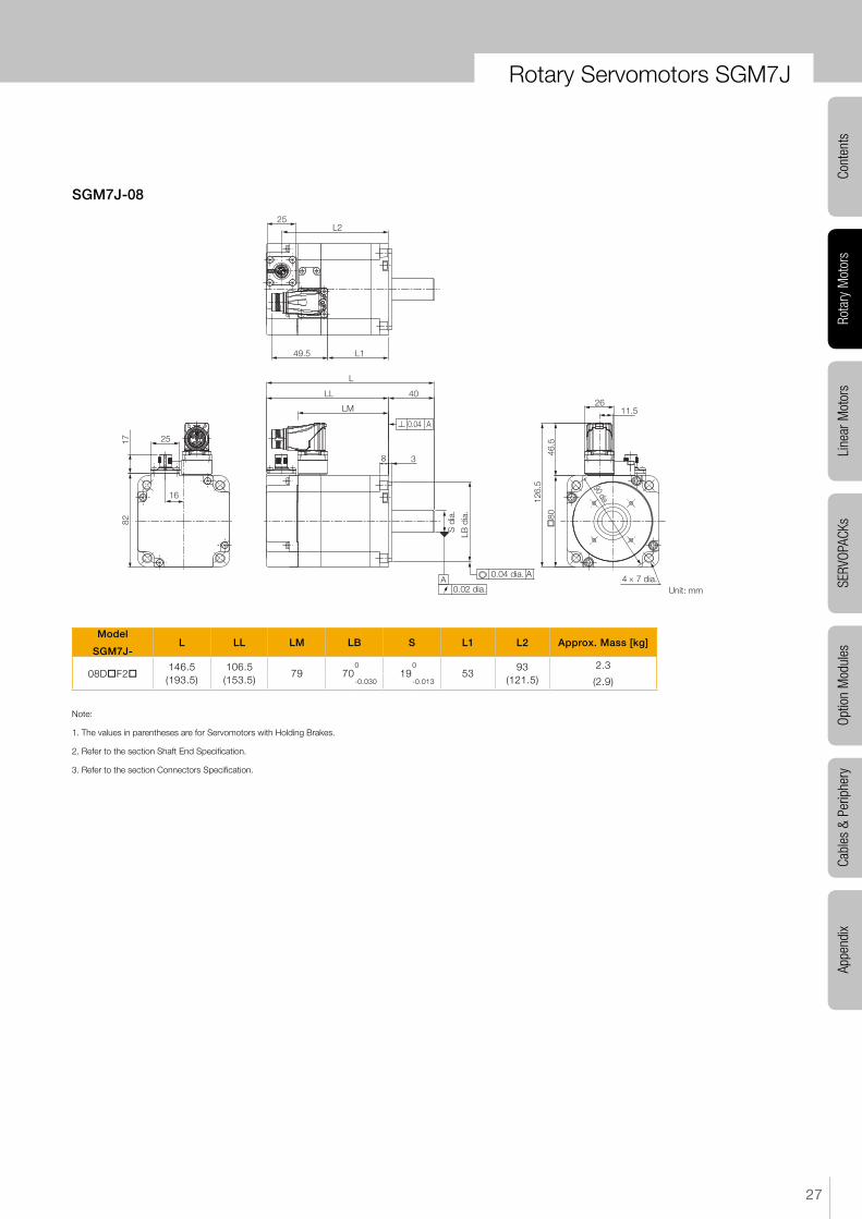
SGM7J-08
Model
SGM7J-L LL LM LB S L1 L2 Approx. Mass [kg]
08DoF2o146.5(193.5)
106.5(153.5)
79 700
190
5393
(121.5)2.3
-0.030 -0.013 (2.9)
Note:
1. The values in parentheses are for Servomotors with Holding Brakes.
2. Refer to the section Shaft End Specification.
3. Refer to the section Connectors Specification.
Unit: mm
25
16
8217
L1
L2
49.5
25
80
4 × 7 dia.
11.526
90 dia.126.
5
46.5
38
0.04 A
LB d
ia.
40
S d
ia.
0.02 dia.
0.04 dia. A
L
LL
LM
A
Rotary Servomotors SGM7J

28 YASKAWA SIGMA-7 | CATALOG
SGM7J-15
Model
SGM7J-L LL LM LB S L1 L2 Approx. Mass [kg]
15DoF2o163.5(196.5)
123.5(156.5)
95.6 1100
190
72110(143)
6.4
-0.035 -0.013 (8.1)
Note:
1. The values in parentheses are for Servomotors with Holding Brakes.
2. Refer to the section Shaft End Specification.
3. Refer to the section Connectors Specification SGM7J-15D.
Rotary Servomotors SGM7J
(without holding brake)
Unit: mm
25
25
27.5
0.04 dia. A
0.02
S d
ia.
LB d
ia.
10 3.5
L
LM
(3)(without holding brake)
LL
40
0.04 A
A4 × 10.2 dia.
28
173.
5
120
53.5
145 dia.
54
25L2
L1

29
Rota
ry M
otor
sCo
nten
tsLi
near
Mot
ors
Cabl
es &
Per
iphe
rySE
RVOP
ACKs
Optio
n M
odul
esAp
pend
ix
Shaft End Specifications
SGM7J-ooooooo
Code Specification
2 Straight without key
6Straight with key and tap for one location
(Key slot is JIS B1301-1996 fastening type.)
Shaft End DetailsServomotor Model SGM7J-
02 04 08 15
Code: 2 (Straight without Key)
LR
S d
ia.
LR 30 40
S 140
190
-0.011 -0.013
Code: 6 (Straight with Key and Tap)
QK
Y
Y
LR
W
T
UP
S di
a.
Cross section Y-Y
LR 30 40
QK 14 22
S 140
190
-0.011 -0.013
W 5 6
T 5 6
U 3 3.5
P M5 × 8L M6 × 10L
� � �
Rotary Servomotors SGM7J

30 YASKAWA SIGMA-7 | CATALOG
Rotary Servomotors SGM7J
Connector Specifications
SGM7J-02 to -15
SGM7J-02 to -08
SGM7J-15
• Encoder Connector Specifications
• Servomotor Connector Specifications
• Servomotor Connector Specifications
Receptacle Size: M12 Part number: 1419959
Model: SACC-MSQ-M12MS-25-3,2 SCO
Manufacturer: Phoenix Contact
Receptacle Size: M23 Part number: 1617905
Model: ST-5EP1N8AAD00S
Manufacturer: Phoenix Contact
Receptacle Size: M17 Part number: 1620448
Model: ST-5EP1N8AA500S
Manufacturer: Phoenix Contact
1 PG 5V2 PG 0V3 FG4 BAT (+)5 BAT (-)6 Data (+)7 Data (-)8 EmptyHousing Shield
1 (Brake)3 U4 V5 Empty6 (Brake)7 WFG FGHousing Shield
1 V2 (Brake)4 (Brake)5 U6 WFG FGHousing Shield
Servomotor Connector Rotational AngleAllowable number of rotations: 10
SGM7G-02 to -15