ROTARY MIXING VALVE WITH BY-PASSbarberi.it/materiale/PDF/ST00119_en.pdf · ROTARY MIXING VALVE WITH...
8
art.41D 1 ROTARY MIXING VALVE WITH BY-PASS art. 41D EN DATA SHEET rev. A ST00119 Barberi ® reserves the right to modify the present information without notice; Barberi ® is not liable for injuries or damages which could occur to things, people or materials due to unsuitable and different applications, other than the suggested, of its articles. Barberi Rubinetterie Industriali s.r.l. • 13018 VALDUGGIA (VC) ITALY • Via Monte Fenera, 7 • Tel. 0039 0163 48.284 r.a. • Fax 0039 0163 48.287 • e-mail: [email protected] • website: http://www.barberi.it Description Barberi ® mixing valves with or without actuator are devices that allow the mixing between two fluids (e.g. warm and cold water) to get the desired temperature. They could be used in heating and refreshing installations, in heating plants, in heat generators (hang-wall boil- ers, wood boilers, heating pumps), in distribution groups. The mixing between fluids is obtained through a shaped rotor that regulates the fluid’s pas- sage. The mixing valves can be used in manual mode or with electrical actuator. Features of these valves are the running nut for pump connection, the male connection to the mani- fold and the bypass on the way back. The by pass on the return will improve the regulation especially when electrical actuators are used. Article range art. 41D 3-ways rotary mixing valve with by-pass / pump connection Technical features Min - max. acceptable temperature(peaks): -20 °C (see suitable fluids) – 130 °C Min - max. working temperature: 0 °C (no frost) – 110 °C Max working pressure: 10 bar Rotor’s torque: under 5 Nm Rotor’s rotation’s angle: 90° Leakage: <0,1% Suitable fluids: water for heating installation, glycoled water(max 50%) Installation connection: M threaded connections UNI ISO 228-1 Materials Valve’s body: brass UNI EN 12165 CW617N Flanges: brass UNI EN 12164 CW614N Rotor: brass UNI EN 12165 CW617N Washers: EPDM Numbered plate: PVC Handle: ABS Working way Mix with closed By-pass Only hot with closed By-pass Only hot with opened By-pass Working way as mixing valve
Transcript of ROTARY MIXING VALVE WITH BY-PASSbarberi.it/materiale/PDF/ST00119_en.pdf · ROTARY MIXING VALVE WITH...

art.41D
1
ROTARY MIXING VALVE WITH BY-PASS
art. 41D
EN DATA SHEETrev.A
ST00119
Barberi® reserves the right to modify the present information without notice; Barberi® is not liable for injuries or damages which could occur to things, people or materials due to unsuitable and different applications, other than the suggested, of its articles.
Barberi Rubinetterie Industriali s.r.l. • 13018 VALDUGGIA (VC) ITALY • Via Monte Fenera, 7 • Tel. 0039 0163 48.284 r.a. • Fax 0039 0163 48.287 • e-mail: [email protected] • website: http://www.barberi.it
Description
Barberi® mixing valves with or without actuator are devices that allow the mixing between two fluids (e.g. warm and cold water) to get the desired temperature. They could be used in heating and refreshing installations, in heating plants, in heat generators (hang-wall boil-ers, wood boilers, heating pumps), in distribution groups.The mixing between fluids is obtained through a shaped rotor that regulates the fluid’s pas-sage. The mixing valves can be used in manual mode or with electrical actuator. Features of these valves are the running nut for pump connection, the male connection to the mani-fold and the bypass on the way back. The by pass on the return will improve the regulation especially when electrical actuators are used.
Article range
art. 41D 3-ways rotary mixing valve with by-pass / pump connection
Technical features
Min - max. acceptable temperature(peaks): -20 °C (see suitable fluids) – 130 °CMin - max. working temperature: 0 °C (no frost) – 110 °CMax working pressure: 10 barRotor’s torque: under 5 NmRotor’s rotation’s angle: 90°Leakage: <0,1%Suitable fluids: water for heating installation, glycoled water(max 50%)Installation connection: M threaded connections UNI ISO 228-1
Materials
Valve’s body: brass UNI EN 12165 CW617N Flanges: brass UNI EN 12164 CW614NRotor: brass UNI EN 12165 CW617NWashers: EPDMNumbered plate: PVCHandle: ABS
Working way
Mix with closed By-pass
Only hot with closed By-pass
Only hot with opened By-pass
Working way as mixing valve
2
ROTARY MIXING VALVE WITH BY-PASS
art. 41D
EN DATA SHEETrev.A
ST00119
Barberi® reserves the right to modify the present information without notice; Barberi® is not liable for injuries or damages which could occur to things, people or materials due to unsuitable and different applications, other than the suggested, of its articles.
Barberi Rubinetterie Industriali s.r.l. • 13018 VALDUGGIA (VC) ITALY • Via Monte Fenera, 7 • Tel. 0039 0163 48.284 r.a. • Fax 0039 0163 48.287 • e-mail: [email protected] • website: http://www.barberi.it
Working way as diverting valve
Deviation with closed By-pass
Only straight way with closed By-pass
Only straight way with opened By-pass
Rotary mixing valve sets the fluid temperature of supply. This setting is obtained by mixing a warm fluid at higher temperature with a warm fluid at a lower temperature within the mixing chamber. The mixing is done by a shaped rotor which allows the closure or the opening of fluids’ passage bores.The three ways valves can be used as mixing valves (by setting the installation’s temperature before the valve) or as diverting valve (by setting the installation’s flow rate before the valve).
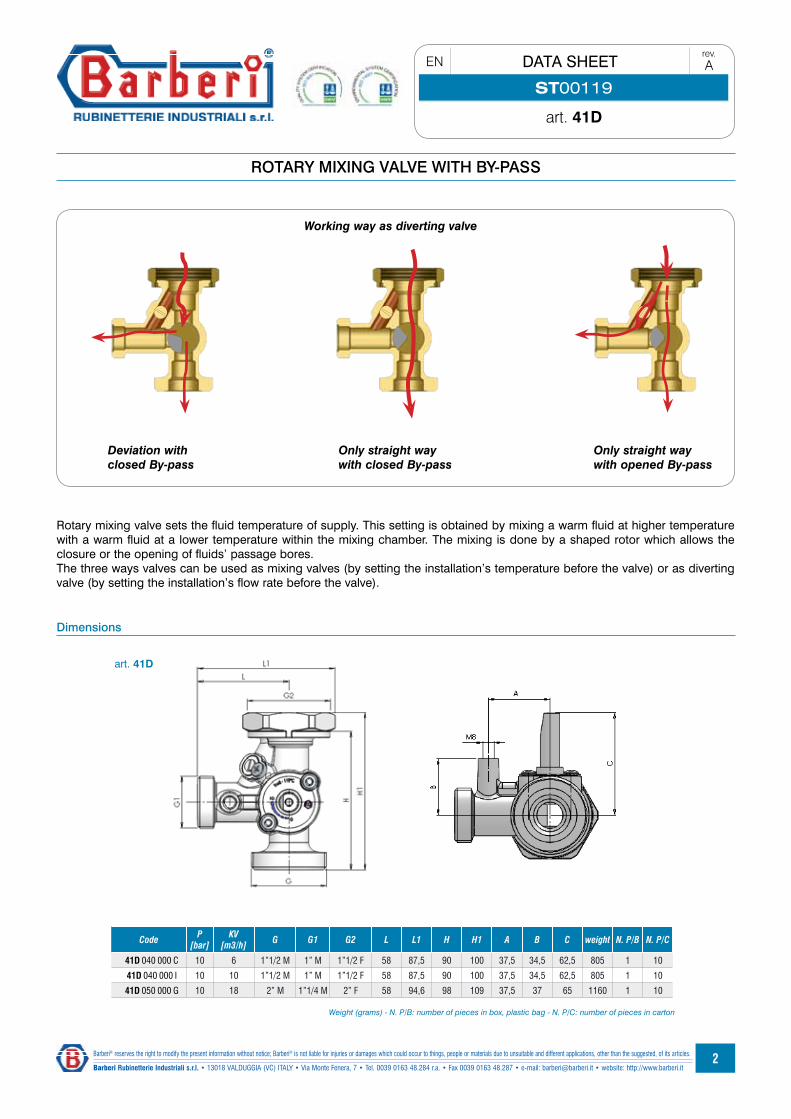
Dimensions
Code P [bar]
KV[m3/h] G G1 G2 L L1 H H1 A B C weight N. P/B N. P/C
41D 040 000 C 10 6 1”1/2 M 1” M 1”1/2 F 58 87,5 90 100 37,5 34,5 62,5 805 1 10
41D 040 000 I 10 10 1”1/2 M 1” M 1”1/2 F 58 87,5 90 100 37,5 34,5 62,5 805 1 10
41D 050 000 G 10 18 2” M 1”1/4 M 2” F 58 94,6 98 109 37,5 37 65 1160 1 10
Weight (grams) - N. P/B: number of pieces in box, plastic bag - N. P/C: number of pieces in carton
art. 41D
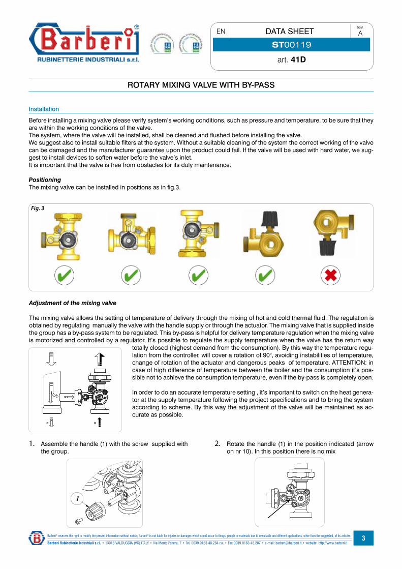
Fig. 3
G
G
1
G
HC
3
ROTARY MIXING VALVE WITH BY-PASS
art. 41D
EN DATA SHEETrev.A
ST00119
Barberi® reserves the right to modify the present information without notice; Barberi® is not liable for injuries or damages which could occur to things, people or materials due to unsuitable and different applications, other than the suggested, of its articles.
Barberi Rubinetterie Industriali s.r.l. • 13018 VALDUGGIA (VC) ITALY • Via Monte Fenera, 7 • Tel. 0039 0163 48.284 r.a. • Fax 0039 0163 48.287 • e-mail: [email protected] • website: http://www.barberi.it
Installation
Before installing a mixing valve please verify system’s working conditions, such as pressure and temperature, to be sure that they are within the working conditions of the valve.The system, where the valve will be installed, shall be cleaned and flushed before installing the valve.We suggest also to install suitable filters at the system. Without a suitable cleaning of the system the correct working of the valve can be damaged and the manufacturer guarantee upon the product could fail. If the valve will be used with hard water, we sug-gest to install devices to soften water before the valve’s inlet.It is important that the valve is free from obstacles for its duly maintenance.
PositioningThe mixing valve can be installed in positions as in fig.3.
Adjustment of the mixing valve
The mixing valve allows the setting of temperature of delivery through the mixing of hot and cold thermal fluid. The regulation is obtained by regulating manually the valve with the handle supply or through the actuator. The mixing valve that is supplied inside the group has a by-pass system to be regulated. This by-pass is helpful for delivery temperature regulation when the mixing valve is motorized and controlled by a regulator. It’s possible to regulate the supply temperature when the valve has the return way
totally closed (highest demand from the consumption). By this way the temperature regu-lation from the controller, will cover a rotation of 90°, avoiding instabilities of temperature, change of rotation of the actuator and dangerous peaks of temperature. ATTENTION: in case of high difference of temperature between the boiler and the consumption it’s pos-sible not to achieve the consumption temperature, even if the by-pass is completely open.
In order to do an accurate temperature setting , it’s important to switch on the heat genera-tor at the supply temperature following the project specifications and to bring the system according to scheme. By this way the adjustment of the valve will be maintained as ac-curate as possible.
1. Assemble the handle (1) with the screw supplied with the group.
2. Rotate the handle (1) in the position indicated (arrow on nr 10). In this position there is no mix

4 3
1
2
1
2
7
8
4
2
1
2
3
4
5
GG
Open
I
G
Close
H
G
2
3
4
ROTARY MIXING VALVE WITH BY-PASS
art. 41D
EN DATA SHEETrev.A
ST00119
Barberi® reserves the right to modify the present information without notice; Barberi® is not liable for injuries or damages which could occur to things, people or materials due to unsuitable and different applications, other than the suggested, of its articles.
Barberi Rubinetterie Industriali s.r.l. • 13018 VALDUGGIA (VC) ITALY • Via Monte Fenera, 7 • Tel. 0039 0163 48.284 r.a. • Fax 0039 0163 48.287 • e-mail: [email protected] • website: http://www.barberi.it
3. Switch on the pump4. Loosen the screw (2) of
the by-pass5. Regulate the screw (3)
of the by-pass to get the correct temperature. Consider that by-pass in the picture on the left is totally closed, the one in the centre is totally open. Close the screw (2) 6. In case the by-pass regulation is not enough, bring the
handle (1) in the position to reach the temperature of the project. By this way if the handle was tampered, the by-pass would limit the supply temperature.
Installation of actuator
The actuator for distribution group is supplied with the com-
ponents you can see in the picture . Actuator(1), Graduated ring (2), Mixing adapt-er (3), Actuator stop screw(4), clamping screw (5). Follow these steps for the installation on the mixing valve.
2. Insert the ring (2) inside the guide of the actuator (1)
3. By pressing and rotating clockwise, turn the handle until the end and stop it.
4. Insert the adaptor (3) and screw the actuator stop screw(4).
1. Look at the graduated ring (2) for the percentage of hot water. Turn the ring as in the picture on the right.
5. Look at the mark on the adapter.
0,0
1,0
2,0
3,0
4,0
5,0
6,0
7,0
8,0
9,0
10,0
11,0
0 1 2 3 4 5 6 7 8 9 10 11 12 13 14 15 16 17 18 19
Q[m3/h]
DP
[m]
0,00
0,10
0,20
0,30
0,40
0,50
0,60
0,70
0,80
0,90
1,00
1,100 2000 4000 6000 8000 10000 12000 14000 16000 18000
Q[l/h]
DP
[bar
]
41D-CKV6
41D-IKV10
41D-GKV18
Q[l/h]
Q[m3/h]
DP
[bar
]
DP
[m]
K
5
ROTARY MIXING VALVE WITH BY-PASS
art. 41D
EN DATA SHEETrev.A
ST00119
Barberi® reserves the right to modify the present information without notice; Barberi® is not liable for injuries or damages which could occur to things, people or materials due to unsuitable and different applications, other than the suggested, of its articles.
Barberi Rubinetterie Industriali s.r.l. • 13018 VALDUGGIA (VC) ITALY • Via Monte Fenera, 7 • Tel. 0039 0163 48.284 r.a. • Fax 0039 0163 48.287 • e-mail: [email protected] • website: http://www.barberi.it
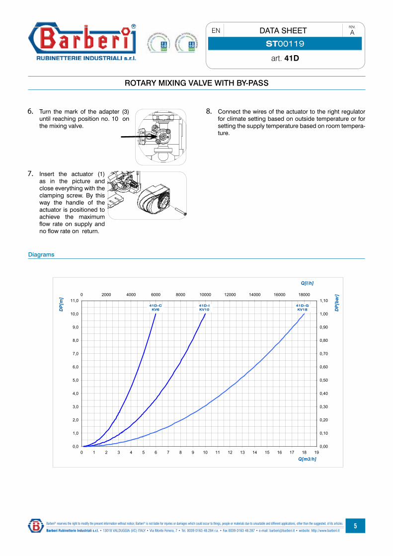
Diagrams
6. Turn the mark of the adapter (3) until reaching position no. 10 on the mixing valve.
7. Insert the actuator (1) as in the picture and close everything with the clamping screw. By this way the handle of the actuator is positioned to achieve the maximum flow rate on supply and no flow rate on return.
8. Connect the wires of the actuator to the right regulator for climate setting based on outside temperature or for setting the supply temperature based on room tempera-ture.

6
ROTARY MIXING VALVE WITH BY-PASS
art. 41D
EN DATA SHEETrev.A
ST00119
Barberi® reserves the right to modify the present information without notice; Barberi® is not liable for injuries or damages which could occur to things, people or materials due to unsuitable and different applications, other than the suggested, of its articles.
Barberi Rubinetterie Industriali s.r.l. • 13018 VALDUGGIA (VC) ITALY • Via Monte Fenera, 7 • Tel. 0039 0163 48.284 r.a. • Fax 0039 0163 48.287 • e-mail: [email protected] • website: http://www.barberi.it
Accessories
Specifications
The specification’s text refers to a specific article reference. Each version of the product obliges the engineer to modify the speci-fication’s text
Art.Ref. 41D 040 000 C3ways rotary mixing valve KV6 with by-pass, handle for manual setting and possibility to assemble an actuator (stroke 90°). Threaded connections G 1”1/2M, G 1”M, running nut G 1”1/2F, 90mm hit’s distance. Body in brass material UNI EN 12165 CW617N. Closing flange UNI EN 12164 CW614N. EPDM washers. PVC numbered plate. ABS handle. Max working pressure 10bar. Max working temperature 110°C. Suitable fluids water or glycoled water (max.50%)
Art.Ref. 41D 040 000 I3ways rotary mixing valve KV10 with by-pass, handle for manual setting and possibility to assemble an actuator (stroke 90°). Threaded connections G 1”1/2M, G 1”M, running nut G 1”1/2F, 90mm hit’s distance. Body in brass material UNI EN 12165 CW617N. Closing flange UNI EN 12164 CW614N. EPDM washers. PVC numbered plate. ABS handle. Max working pressure 10bar. Max working temperature 110°C. Suitable fluids water or glycoled water (max.50%)
Art.Ref. 41D 050 000 G3ways rotary mixing valve KV6 with by-pass, handle for manual setting and possibility to assemble an actuator (stroke 90°). Threaded connections G 2”M, G 1”1/4M, running nut G 2”F, 98mm hit’s distance. Body in brass material UNI EN 12165 CW617N. Closing flange UNI EN 12164 CW614N. EPDM washers. PVC numbered plate. ABS handle. Max working pressure 10bar. Max working temperature 110°C. Suitable fluids water or glycoled water (max.50%)
Art. M03Compact actuator for mixing valves, running angle 90°, for 3 points and on/off setting. Comes complete with blocking screw, mixing valve adaptors, anti-rotation pin, 1,5m integrated cable.
Torque: 10 NmRunning time: 60 s, 120 sPower supply: 230 V , 24 VFrequency: 50 Hz
code V control running time [s] N° poles
Torque [Nm]
M030101DAB 230 V 3 pt. 120 3 10
M030101GAB 230 V 3 pt. 120 6 10
M030101DBB 230 V 3 pt. 60 3 10
M030101GBB 230 V 3 pt. 60 6 10
M030101AAB 230 V on/off 120 3 10
M030101HAB 230 V on/off 120 6 10
M030101ABB 230 V on/off 60 3 10
M030101HBB 230 V on/off 60 6 10
M030102DAB 24 V 3 pt. 120 3 10
M030102GAB 24 V 3 pt. 120 6 10
M030102DBB 24 V 3 pt. 60 3 10
M030102GBB 24 V 3 pt. 60 6 10
M030102AAB 24 V on/off 120 3 10
M030102ABB 24 V on/off 60 3 10
7
ROTARY MIXING VALVE WITH BY-PASS
art. 41D
EN DATA SHEETrev.A
ST00119
Barberi® reserves the right to modify the present information without notice; Barberi® is not liable for injuries or damages which could occur to things, people or materials due to unsuitable and different applications, other than the suggested, of its articles.
Barberi Rubinetterie Industriali s.r.l. • 13018 VALDUGGIA (VC) ITALY • Via Monte Fenera, 7 • Tel. 0039 0163 48.284 r.a. • Fax 0039 0163 48.287 • e-mail: [email protected] • website: http://www.barberi.it
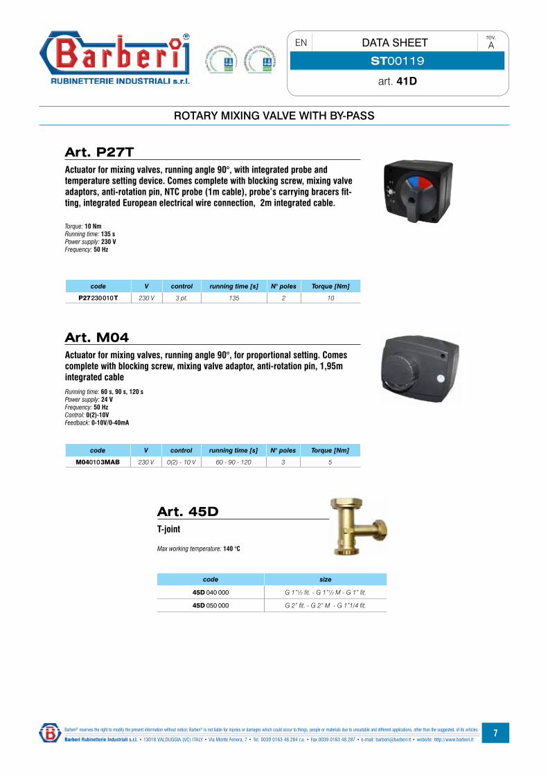
Running time: 60 s, 90 s, 120 sPower supply: 24 VFrequency: 50 HzControl: 0(2)-10VFeedback: 0-10V/0-40mA
Torque: 10 NmRunning time: 135 sPower supply: 230 VFrequency: 50 Hz
code V control running time [s] N° poles Torque [Nm]
M040103MAB 230 V 0(2) - 10 V 60 - 90 - 120 3 5
code V control running time [s] N° poles Torque [Nm]
P27230010T 230 V 3 pt. 135 2 10
Art. P27TActuator for mixing valves, running angle 90°, with integrated probe and temperature setting device. Comes complete with blocking screw, mixing valve adaptors, anti-rotation pin, NTC probe (1m cable), probe’s carrying bracers fit-ting, integrated European electrical wire connection, 2m integrated cable.
Art. M04Actuator for mixing valves, running angle 90°, for proportional setting. Comes complete with blocking screw, mixing valve adaptor, anti-rotation pin, 1,95m integrated cable
Art. 45DT-joint
Max working temperature: 140 °C
code size
45D 040 000 G 1”½ fit. - G 1”½ M - G 1” fit.
45D 050 000 G 2” fit. - G 2” M - G 1”1/4 fit.
8
ROTARY MIXING VALVE WITH BY-PASS
art. 41D
EN DATA SHEETrev.A
ST00119
Barberi® reserves the right to modify the present information without notice; Barberi® is not liable for injuries or damages which could occur to things, people or materials due to unsuitable and different applications, other than the suggested, of its articles.
Barberi Rubinetterie Industriali s.r.l. • 13018 VALDUGGIA (VC) ITALY • Via Monte Fenera, 7 • Tel. 0039 0163 48.284 r.a. • Fax 0039 0163 48.287 • e-mail: [email protected] • website: http://www.barberi.it
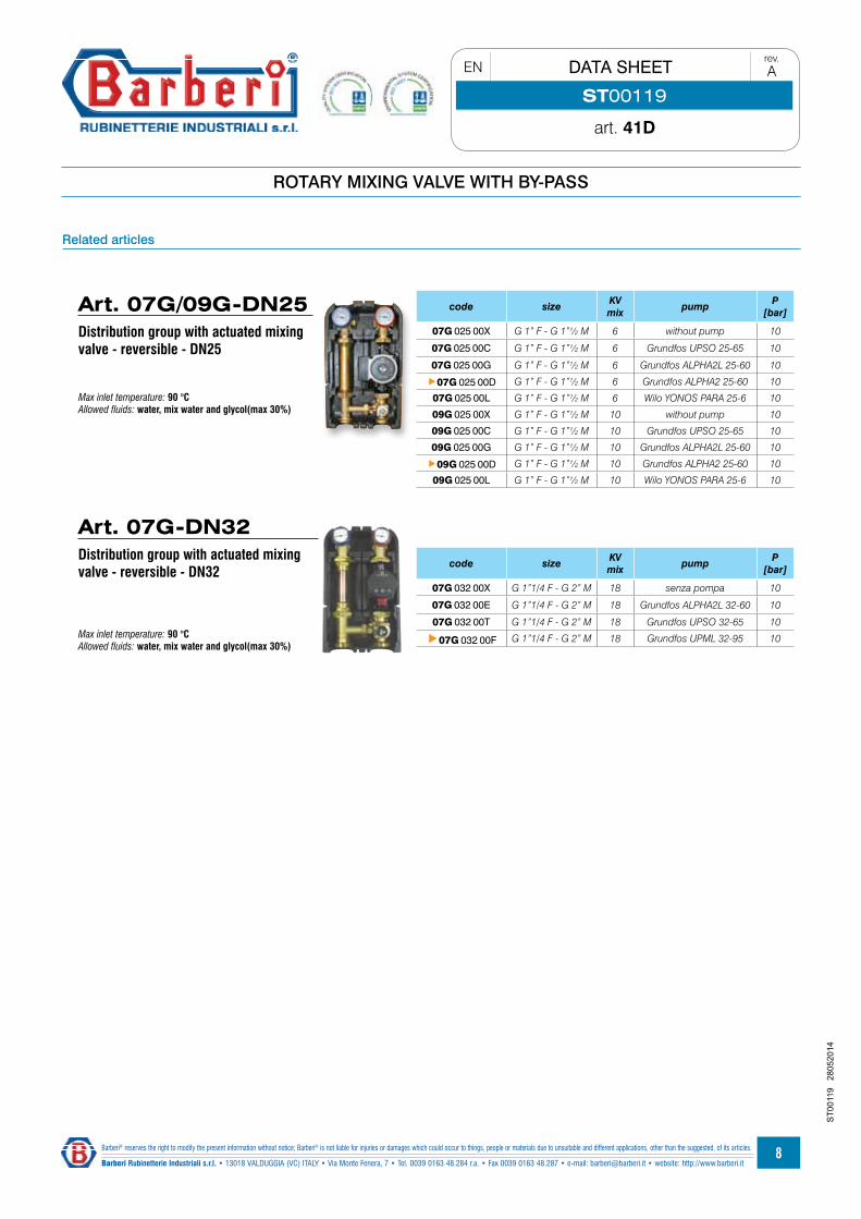
Max inlet temperature: 90 °CAllowed fluids: water, mix water and glycol(max 30%)
code size KV mix pump P
[bar]
07G 032 00X G 1”1/4 F - G 2” M 18 senza pompa 10
07G 032 00E G 1”1/4 F - G 2” M 18 Grundfos ALPHA2L 32-60 10
07G 032 00T G 1”1/4 F - G 2” M 18 Grundfos UPSO 32-65 10
07G 032 00F G 1”1/4 F - G 2” M 18 Grundfos UPML 32-95 10
Related articles
ST0
0119
28
0520
14
Art. 07G/09G-DN25Distribution group with actuated mixing valve - reversible - DN25
Max inlet temperature: 90 °CAllowed fluids: water, mix water and glycol(max 30%)
code size KV mix pump P
[bar]
07G 025 00X G 1” F - G 1”½ M 6 without pump 10
07G 025 00C G 1” F - G 1”½ M 6 Grundfos UPSO 25-65 10
07G 025 00G G 1” F - G 1”½ M 6 Grundfos ALPHA2L 25-60 10
07G 025 00D G 1” F - G 1”½ M 6 Grundfos ALPHA2 25-60 10
07G 025 00L G 1” F - G 1”½ M 6 Wilo YONOS PARA 25-6 10
09G 025 00X G 1” F - G 1”½ M 10 without pump 10
09G 025 00C G 1” F - G 1”½ M 10 Grundfos UPSO 25-65 10
09G 025 00G G 1” F - G 1”½ M 10 Grundfos ALPHA2L 25-60 10
09G 025 00D G 1” F - G 1”½ M 10 Grundfos ALPHA2 25-60 10
09G 025 00L G 1” F - G 1”½ M 10 Wilo YONOS PARA 25-6 10
Art. 07G-DN32Distribution group with actuated mixing valve - reversible - DN32