ROTARY HEAT EXCHANGER - HOLTOP · ROTARY HEAT EXCHANGER Beijing Holtop Artificial Environment...
16
ROTARY HEAT EXCHANGER Beijing Holtop Artificial Environment Technology Co., Ltd ISO9001:2000 approved company Energy Recovery Ventilation Specialist
Transcript of ROTARY HEAT EXCHANGER - HOLTOP · ROTARY HEAT EXCHANGER Beijing Holtop Artificial Environment...

ROTARY HEAT EXCHANGER
Beijing Holtop Artificial Environment Technology Co., Ltd ISO9001:2000 approved company
Energy Recovery Ventilation Specialist

Holtop is dedicated to the research and technology development in the filed of indoor air quality. It is the leading company in China who professionally produces heat recovery ventilation system.
Covering a land of 20000 square meters, Holtop was created in May, 2002 furnished with first-class plants and equipments. Through innovation, it developed its own key components like plate and ro-tary heat exchangers for various heat & energy recovery systems. It provides now full lines of prod-ucts covering 5 series and 98 specifications which can basically satisfy the needs of various airflows and installations worldwidely.
Holtop is trusted by the users for its advanced technology, superb product quality and all-around ser-vices. By the end of year 2006, Holtop has supplied successfully to over 3000 customers in the do-mestic market and exported its products to Japan, Korea, Russia, Italy, Belgium, Australia, New Zea-land, etc.
Let's join together to contribute to our commitment of energy saving and pollution reduction.
COMPANY BRIEF INTRODUCTION TO COMPANY
ENERGY RECOVERY VENTILATION SPECIALIST
2

CONTENTS
BRIEF INTRODUTION TO COMPANY WORKING PRINCIPLE TECHNICAL SUMMERIZATION SPECIFICATIONS AND DIMENSIONS APPLICATIONS
01
03
04
10
12

SELECTION GUIDE
Working Principle Rotary heat exchanger is composed of alveolate heat wheel, case, drive system and sealing parts. The ex-haust and outdoor air pass through half of the wheel separately, when the wheel rotates, the heat and mois-ture are exchanged between the exhaust and outdoor air. The energy recovery efficiency is up to 70% to 90%.
Entering the cold air half When the wheel enters the cold air half suddenly from warm air half, temperature drops quickly. Heat is absorbed by cold air and the temperature of cold air rises slightly. Heat exchange efficiency is high at this moment due to the bigger temperature difference. Mean-while, the moisture on the wheel goes into the dry and cold air.
1
2
3
4
5
6
In the middle of cold air half When the wheel rotates to the mid-dle of cold air half, the air tempera-ture continues to drop and moisture continues to dissipate. The dry and cold air is heated and humidified continually. Heat exchange effi-ciency drops due to the reducing temperature difference.
Leaving the cold air half When the wheel is leaving the cold air half, its temperature and humidity become same as the cold air. The heat exchange between the wheel and cold air ends. The temperature and hu-midity of the cold air stop changing. Wheel temperature drops to minimum and wheel dryness increases to maximum.
Entering the warm air half Warm air passes though the wheel in reverse direction. Heat exchange efficiency is high at this moment due to the bigger temperature difference. Tempera-ture of this humid and warm air drops quickly, and its moisture is absorbed heavily by the wheel.
In the middle of warm air half When the wheel rotates to the middle of the warm half, efficiency drops because the wheel temperature rises and the temperature difference drops. The moisture absorbent coated on the surface of the wheel is becoming saturated, the moisture absorption capacity decrease.
Leaving the warm air half The wheel is heated completely. Its temperature is same as the warm air and the humidity ex-change stops. The efficiency is zero.
Dry and cold air
Humid and warm air
4

5
TECHNICAL SUMMERIZATION
HR T-3000-4 D A-A 2-E ① ② ③ ④⑤⑥⑦⑧⑨ ① Stands for Holtop rotary heat exchanger ② T/S T stands for total heat wheel. The wheel is made by aluminum foils coated with 3A molecular sieve moisture absor-bent, which enables the wheel to exchange both temperature and humidity, in another word to exchange both sensi-ble heat and latent heat. S stands for sensible heat wheel. It generally recovers no latent heat, only when the condensation occurs, can it recover part of that latent heat. ③ Stands for effective wheel diameter
④ 1/4/8/16/24 stands for segment amount of the heat wheel, see P6.
⑤ A/B/C/D/E stands for the casing code, see P5
⑥A/D stands for type of casing. A stands for inner-loaded type which has no side panels and usually is loaded inside the AHU. D stands for open type which has side panels and is installed between the ducts. ⑦ A/B/C/D/E/┄P stands for the type of installation, see P8. ⑧ 1/2/3/4 stands for the motor position, see P8. ⑨ Stands for intelligent control. It’s optional, users can use their own control device to control the ON/OFF of wheel.
Model Description
Wheel Materials
The sensible heat wheel is made by aluminum foils of 0.05mm thickness. And the total heat wheel is made by aluminum foils coated with 3A molecular sieve of 0.07mm thick-ness.
Silicon gel absorbs both moisture and odor by capillarity.
Moisture absorption coating Aluminum foil Adhesive
Molecular sieve selectively absorbs moisture and expels odor by molecular lattice.

TECHNICAL SUMMERIZATION
Casing Construction
Specifications
Casing A Plate structure, made of aluzinc, one-piece.
Casing B Plate structure, made of aluzinc, one-piece. For right and left ducted, the upper side should add a vertical beam.
Casing C Plate structure, made of aluzinc, in two sections. For right and left ducted, the upper side should add a vertical beam.
Casing D Frame structure, made of aluminum profiles with aluzinc plates, in two sections, assembly at installation.
Casing E Frame structure, made of aluminum profiles with aluzinc plates, casing delivered in parts and assembled at installation.
The ways of casing should be selected according to the application spaces as well as transportation capability and conditions at installation. Over segmentation will increase the assembly work, and overlarge size will cause difficulties in transportation.
Casing Type
6

7
TECHNICAL SUMMERIZATION
Wheel Construction The wheel of the rotary heat exchanger is made of alternating layers of flat and corrugated aluminum foil to form the alveolate shape. Various height of corrugation is available. Flat surface ensures minimum leakage. Interior spokes are used to mechanically bond the rotor’s laminations. These are threaded at the hub and welded at the periphery.
The segmentations of rotor should be selected according to the application spaces as well as transporta-tion capability and conditions at installation. Over segmentation will increase the assembly work, and overlarge size will cause difficulties in transportation.
Specifications
Whe
el S
egm
enta
tions
Type 1 One-piece
Type 4 4 segments, assembly at installa-tion.
Type 8/16/24 8 segments along circle, assem-bly at installation. 2600≤d≤3200, no segment along diameter 3400≤d≤4000, 2 segments along diameter 4200≤d≤5000, 3 segments along diameter
TECHNICAL SUMMERIZATION
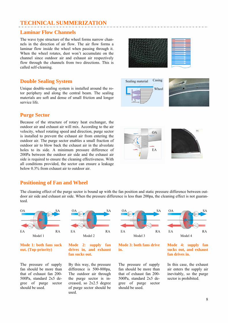
Laminar Flow Channels The wave type structure of the wheel forms narrow chan-nels in the direction of air flow. The air flow forms a laminar flow inside the wheel when passing through it. When the wheel rotates, dust won’t accumulate on the channel since outdoor air and exhaust air respectively flow through the channels from two directions. This is called self-cleaning.
Double Sealing System
Unique double-sealing system is installed around the ro-tor periphery and along the central beam. The sealing materials are soft and dense of small friction and longer service life.
Sealing material Casing
Wheel
Purge Sector Because of the structure of rotary heat exchanger, the outdoor air and exhaust air will mix. According to the air velocity, wheel rotating speed and direction, purge sector is installed to prevent the exhaust air from entering the outdoor air. The purge sector enables a small fraction of outdoor air to blow back the exhaust air in the alveolate holes to its side. A minimum pressure difference of 200Pa between the outdoor air side and the exhaust air side is required to ensure the cleaning effectiveness. With all conditions provided, the sector can ensure a leakage below 0.3% from exhaust air to outdoor air.
OA
EA
Positioning of Fan and Wheel The cleaning effect of the purge sector is bound up with the fan position and static pressure difference between out-door air side and exhaust air side. When the pressure difference is less than 200pa, the cleaning effect is not guaran-teed.
Model 1 Model 2 Model 3 Model 4
Mode 1: both fans suck out. (Top-priority)
Mode 2: supply fan drives in, and exhaust fan sucks out.
Mode 3: both fans drive in.
Mode 4: supply fan sucks out, and exhaust fan drives in.
8
The pressure of supply fan should be more than that of exhaust fan 200-500Pa, standard 2x5 de-gree of purge sector should be used.
By this way, the pressure difference is 500-800pa, The outdoor air through the purge sector is in-creased, so 2x2.5 degree of purge sector should be used.
The pressure of supply fan should be more than that of exhaust fan 200-500Pa, standard 2x5 de-gree of purge sector should be used.
In this case, the exhaust air enters the supply air inevitably, so the purge sector is prohibited.
OA OA OA OA SA SA SA SA
EA EA EA EA RA RA RA RA

TECHNICAL SUMMERIZATION
Bearing and Lubrication
The hub of the wheel is equipped with life-time- lubricated ball bearing or roller bearing, and with covers at both sides. No maintenance is required under normal usage.
Installation Types and Motor Position
The motor is installed at the corner of the rotary heat exchanger, the position of the corner is marked from no. 1 to 4, and the motor positions is optional.
Exhaust air Outdoor air
9

10
TECHNICAL SUMMERIZATION
Driving System
The wheel is drove to rotate by this system. The drive system is composed of motor, turbine-worm reducer, belt pulley and V belt. The motor is installed on the special bracket tension-ing by the spring, it can ensure the gradually loose of V-belt in case of sudden stop.
Operation control
Motor voltage is 380V/3ph/50Hz, with the turbine-worm reducer, the wheel rotates at about 10 rpm steadily.
Standardly, we offer wheels without operation control device. However as an option, we offer ZK-100 intelligent controller which has following functions:
● Various rotary speed control by instruction signal from the exterior sensor. Speed can be steplessly ad-justed.
● Manual set of rotary speed
● Automatic temperature sensing and running mode selection.
● Fault alarm and display
● Overload and undervoltage protection
Winter Operation Absolute Humidity d(g/kg)
Temperature t (
C)
Enthalpy i(kj/kg)
OA-RA frost condition
Frost on rotary heat exchanger
OA-OA1 preheat OA
RA-RA1 preheat RA
RA-RA2 reduce RA temperature
The rotary heat exchanger may frost in the ex-tremely cold winter. Frost usually occurs in the exhaust air side. It would result in blockage and airflow reducing, but do no harm to the wheel. As shown on the graph, when the line connecting OA to RA across the 100% relative humidity curve, the wheel will frost. To prevent this, the air should be pre-handled till conditions such as OA1, RA1 or RA2, thus connecting line between OA1 and RA1(RA2) would not pass across the saturation humidity curve.
To avoid the frost blockage, the wheel should rotate at low speed of 2rpm or intermittently, for example stops 10 seconds each 10 minutes of operation. However, under no circumstance should the wheel stop for long period since dusts will get gathered on the wheel, resulting in lower recovery efficiency and ventilation deficiency in a worse case.
Ways of frost protection
30
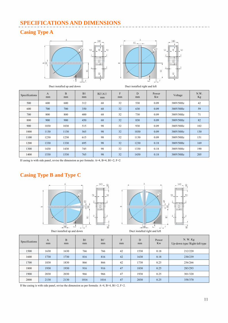
SPECIFICATIONS AND DIMENSIONS Casing Type A
Specifications A mm
B mm
B1 mm
B2(A1) mm
F mm
D mm
Power Kw
Voltage N.W. Kg
500 600 600 312 68 32 530 0.09 380V50Hz 42
600 700 700 350 68 32 630 0.09 380V50Hz 59
700 800 800 400 68 32 730 0.09 380V50Hz 71
800 900 900 450 68 32 830 0.09 380V50Hz 82
900 1030 1030 515 98 32 930 0.09 380V50Hz 102
1000 1130 1130 565 98 32 1030 0.09 380V50Hz 130
1100 1230 1230 615 98 32 1130 0.09 380V50Hz 151
1200 1330 1330 695 98 32 1230 0.18 380V50Hz 169
1300 1430 1430 745 98 32 1330 0.18 380V50Hz 190
1400 1530 1530 765 98 32 1430 0.18 380V50Hz 205
Duct installed up and down Duct installed right and left
Casing Type B and Type C
Specifications A mm
B mm
B1 mm
F mm
D mm
Power Kw
N. W. Kg Up-down type/Right-left type
1500 1630 1630 766 42 1530 0.18 212/220
1600 1730 1730 816 42 1630 0.18 230/239
1700 1830 1830 866 42 1730 0.25 256/266
1800 1930 1930 916 47 1830 0.25 283/293
1900 2030 2030 966 47 1930 0.25 301/320
2000 2130 2130 1016 47 2030 0.25 358/370
B1` mm
766
816
866
916
966
1016
If casing is with side panel, revise the dimension as per formula: A+4, B+4, B1+2, F+2
Duct installed up and down Duct installed right and left
If the casing is with side panel, revise the dimension as per formula: A+4, B+4, B1+2, F+2.
11

SPECIFICATIONS AND DIMENSIONS
Casing Type D and Type E
Specifications A mm
B mm
C mm
F mm
D mm
Power Kw
Weight Kg
2200 2400 2400 400 40 2230 0.37 420
2400 2600 2600 400 40 2430 0.37 500
2600 2800 2800 400 40 2630 0.37 570
2800 3000 3000 400 40 2830 0.37 860
3000 3200 3200 430 70 3030 0.55 950
3200 3400 3400 430 70 3230 0.55 1039
E mm
50
50
50
50
70
70
3400 3600 3600 430 70 70 3430 0.55 1110
3600 3800 3800 430 70 70 3630 0.55 1220
3800 4000 4000 430 70 70 3830 0.55 1360
4000 4200 4200 430 70 70 4030 0.75 1500
4200 4400 4400 430 70 70 4230 0.75 1645
4400 4600 4600 430 70 70 4430 0.75 1750
4600 4800 4800 430 70 70 4630 1.1 1830
4800 5000 5000 430 70 70 4830 1.1 1980
5000 5200 5200 430 70 70 5030 1.1 2100
Duct installed up and down Duct installed right and left
12

APPLICATIONS
Selection Program
We have developed a calculation program for simple selection of a rotary heat exchanger model. It can not only be used as a single design selection program, but can also be combined into your program by DLL. We can add it to your program upon your request, too. Please contact us for the selection program.
13

Airflow (m3/h)
Wheel diameter (mm)
Air resistance (Pa)
Temperature efficiency (%)
Outdoor air Exhaust air
Airflow velocity (m/s)
APPLICATIONS
Selection Chart
14
APPLICATIONS
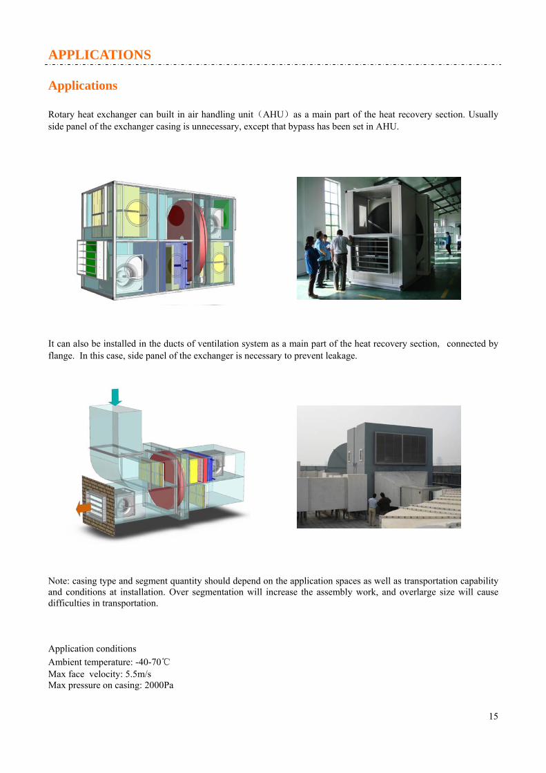
Applications
Rotary heat exchanger can built in air handling unit(AHU)as a main part of the heat recovery section. Usually side panel of the exchanger casing is unnecessary, except that bypass has been set in AHU.
It can also be installed in the ducts of ventilation system as a main part of the heat recovery section, connected by flange. In this case, side panel of the exchanger is necessary to prevent leakage.
Note: casing type and segment quantity should depend on the application spaces as well as transportation capability and conditions at installation. Over segmentation will increase the assembly work, and overlarge size will cause difficulties in transportation.
Application conditions Ambient temperature: -40-70℃ Max face velocity: 5.5m/s Max pressure on casing: 2000Pa
15

Beijing Holtop Artificial Environment Technology Co., Ltd Factory address : No.158 Hanjiachuan Road, Haidian District, Beijing China International marketing center Address: Room 2-1108 Industrial Plaza, Tina An Hi-Tech Ecological Park, No. 730 Yingbin Road, Panyu District, Guangzhou, China
Tel:0086-20-39388201
Fax: 0086-20-39388202
Website:www.holtop.com E-mail: [email protected]
Data is subject to changes without notification due to product improvement