Rotary Dampers · s 2 Vane Dashpots Continuous Rotation Dashpots Certificate No. FM22163 Angle of...
20
® Rotary Dampers
Transcript of Rotary Dampers · s 2 Vane Dashpots Continuous Rotation Dashpots Certificate No. FM22163 Angle of...
®
Rotary Dampers
1
Cat
alog
ue In
dex
S-CRD
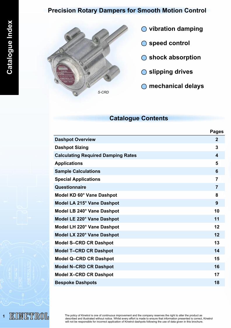
vibration damping
speed control
shock absorption
slipping drives
mechanical delays
Precision Rotary Dampers for Smooth Motion Control
Catalogue Contents
PagesDashpot Overview 2Dashpot Sizing 3Calculating Required Damping Rates 4Applications 5Sample Calculations 6Special Applications 7Questionnaire 7Model KD 60° Vane Dashpot 8Model LA 215° Vane Dashpot 9Model LB 240° Vane Dashpot 10Model LE 220° Vane Dashpot 11Model LH 220° Vane Dashpot 12Model LX 220° Vane Dashpot 12Model S–CRD CR Dashpot 13Model T–CRD CR Dashpot 14Model Q–CRD CR Dashpot 15Model N–CRD CR Dashpot 16Model X–CRD CR Dashpot 17Bespoke Dashpots 18
The policy of Kinetrol is one of continuous improvement and the company reserves the right to alter the product asdescribed and illustrated without notice. Whilst every effort is made to ensure that information presented is correct, Kinetrolwill not be responsible for incorrect application of Kinetrol dashpots following the use of data given in this brochure.
Dashpots
2
Vane Dashpots
Continuous Rotation Dashpots
Certificate No. FM22163
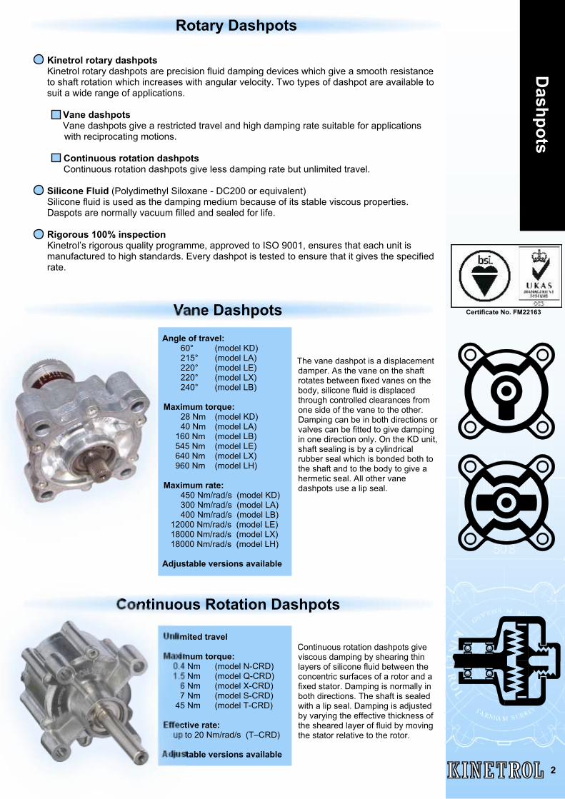
Angle of travel:60° (model KD)215° (model LA)220° (model LE)220° (model LX)240° (model LB)
Maximum torque:28 Nm (model KD)40 Nm (model LA)
160 Nm (model LB) 545 Nm (model LE) 640 Nm (model LX) 960 Nm (model LH)
Maximum rate:450 Nm/rad/s (model KD)300 Nm/rad/s (model LA)400 Nm/rad/s (model LB)
12000 Nm/rad/s (model LE) 18000 Nm/rad/s (model LX) 18000 Nm/rad/s (model LH)
Adjustable versions available
The vane dashpot is a displacementdamper. As the vane on the shaftrotates between fixed vanes on thebody, silicone fluid is displacedthrough controlled clearances fromone side of the vane to the other.Damping can be in both directions orvalves can be fitted to give dampingin one direction only. On the KD unit,shaft sealing is by a cylindricalrubber seal which is bonded both tothe shaft and to the body to give ahermetic seal. All other vanedashpots use a lip seal.
Unlimited travel
Maximum torque: 0.4 Nm (model N-CRD) 1.5 Nm (model Q-CRD) 6 Nm (model X-CRD) 7 Nm (model S-CRD) 45 Nm (model T-CRD)
Effective rate: up to 20 Nm/rad/s (T–CRD)
Adjustable versions available
Continuous rotation dashpots giveviscous damping by shearing thinlayers of silicone fluid between theconcentric surfaces of a rotor and afixed stator. Damping is normally inboth directions. The shaft is sealedwith a lip seal. Damping is adjustedby varying the effective thickness ofthe sheared layer of fluid by movingthe stator relative to the rotor.
Kinetrol rotary dashpotsKinetrol rotary dashpots are precision fluid damping devices which give a smooth resistanceto shaft rotation which increases with angular velocity. Two types of dashpot are available tosuit a wide range of applications.
Vane dashpotsVane dashpots give a restricted travel and high damping rate suitable for applications
with reciprocating motions.
Continuous rotation dashpotsContinuous rotation dashpots give less damping rate but unlimited travel.
Silicone Fluid (Polydimethyl Siloxane - DC200 or equivalent)Silicone fluid is used as the damping medium because of its stable viscous properties.Daspots are normally vacuum filled and sealed for life.
Rigorous 100% inspectionKinetrol’s rigorous quality programme, approved to ISO 9001, ensures that each unit ismanufactured to high standards. Every dashpot is tested to ensure that it gives the specifiedrate.
Rotary Dashpots
Das
hpot
Siz
ing
3
General Notes
For calculation purposes the rotation speed of the dashpot is given in RADIANS per second (1 radian =57.3°). The significance of a radian is that if, for example, a 1 metre radius lever rotates through 1 radian,the end of the lever moves 1 metre, a distance equal to the radius.
Damping RATE is defined here as TORQUE divided by ROTATION SPEED. Note that a dashpot with ahigh rate may not necessarily be working at a high torque. For example, may have a rate of 100Nm/rad/s; however, it may be rotated at 1/10 rad/s so that the damping torque produced is 10 Nm whichis not numerically equal to the rate.
Dashpot Selection
To select a suitable dashpot for an application, the suggested procedure is to first establish the RATErequired. Most applications can be reduced to one of the cases shown opposite. The formula concernedwill give the RATE.
Having established the rate required, the type of dashpot (vane or continuous rotation) must be selected.This usually depends on the angle of travel required.
It is recommended that initially an adjustable dashpot is used in an application. This allows the exactdamping rate to be established. Subsequent units can then be supplied with fixed rates based onmeasurement of the adjustable unit as set on the application.
Vane Dashpots - (High rate, restricted travel)
Establish the rate from the formula for one of the cases opposite (or otherwise).
Check that the maximum shaft torque does not exceed the maximum allowable.Note that max. torque = RATE x max. speed of rotation.
For a vane dashpot the RATE does not vary much with speed and so can be used tospecify the unit.
Temperature Effects
-10 0 10 80706050403020Temperature (°C)
250
0
50
100
150
200
Act
ual R
ate/
Sta
ted
Rat
e (%
)
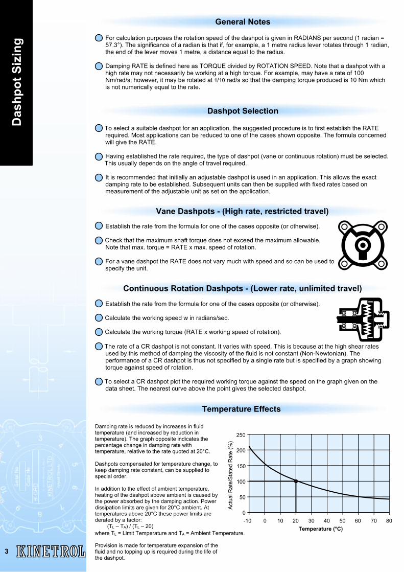
Damping rate is reduced by increases in fluidtemperature (and increased by reduction intemperature). The graph opposite indicates thepercentage change in damping rate withtemperature, relative to the rate quoted at 20°C.
Dashpots compensated for temperature change, tokeep damping rate constant, can be supplied tospecial order.
In addition to the effect of ambient temperature,heating of the dashpot above ambient is caused bythe power absorbed by the damping action. Powerdissipation limits are given for 20°C ambient. Attemperatures above 20°C these power limits arederated by a factor:
(TL – TA) / (TL – 20)
Provision is made for temperature expansion of thefluid and no topping up is required during the life ofthe dashpot.
where TL = Limit Temperature and TA = Ambient Temperature.
Continuous Rotation Dashpots - (Lower rate, unlimited travel)
Establish the rate from the formula for one of the cases opposite (or otherwise).
Calculate the working speed w in radians/sec.
Calculate the working torque (RATE x working speed of rotation).
The rate of a CR dashpot is not constant. It varies with speed. This is because at the high shear ratesused by this method of damping the viscosity of the fluid is not constant (Non-Newtonian). Theperformance of a CR dashpot is thus not specified by a single rate but is specified by a graph showingtorque against speed of rotation.
To select a CR dashpot plot the required working torque against the speed on the graph given on thedata sheet. The nearest curve above the point gives the selected dashpot.
Calculating R
equiredD
amping R
ates
4
T
W
Conversion factors
English Units
Metric Units
1 rad = 57.3°1 Nm = 8.85 lbf.ins
1 RPM = 0.1047 rad/s1 lbf = 4.45 N
1 lbf.ins = 0.113 Nm9.81 N = 1 kgf = 1 kp
Given quantity and unit
F N = force of weight on end of lever t s = time taken to move thisdistance
M kg = mass
L m = effective length of lever w rad/s = speed of rotation V m/s = velocity of massd m = distance moved by end of lever T Nm = torque applied to shaft f Hz = frequency of vibration
Given quantity and unit
F lbf = force of weight on end of lever t s = time taken to move thisdistance
M lbf = mass
L in = effective length of lever w rad/s = speed of rotation V in/s = velocity of massd in = distance moved by end of lever T lbf.ins = torque applied to shaft f Hz = frequency of vibration
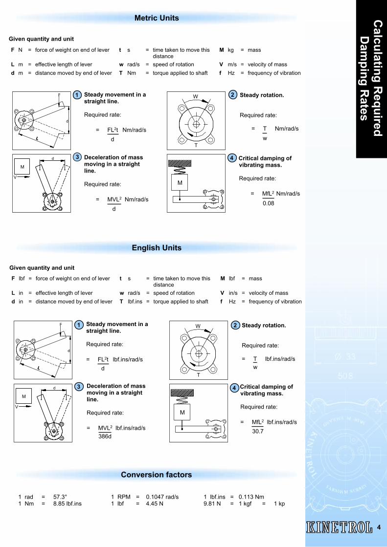
Deceleration of massmoving in a straightline.
Required rate:
= MVL2 lbf.ins/rad/s386d
3
Steady movement in astraight line.
Required rate:
= FL2t lbf.ins/rad/sd
1 Steady rotation.
Required rate:
= T lbf.ins/rad/sw
2
Critical damping ofvibrating mass.
Required rate:
= MfL2 lbf.ins/rad/s30.7
4
Steady movement in astraight line.
Required rate:
= FL2t Nm/rad/sd
1 Steady rotation.
Required rate:
= T Nm/rad/sw
2
Deceleration of massmoving in a straightline.
Required rate:
= MVL2 Nm/rad/sd
3 Critical damping ofvibrating mass.
Required rate:
= MfL2 Nm/rad/s0.08
4
L
d
F
T
W
M
V
d
M
M
L
d
F
M
V
d
App
licat
ions
5
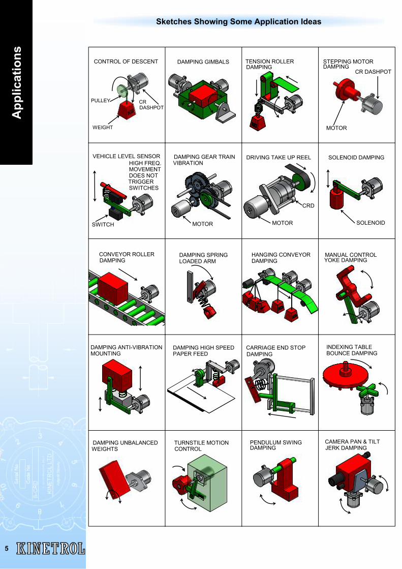
Sketches Showing Some Application Ideas
WEIGHT
CONTROL OF DESCENT
CRDASHPOT
PULLEY
DAMPING GIMBALS TENSION ROLLERDAMPING
MOTOR
STEPPING MOTORDAMPING CR DASHPOT
VEHICLE LEVEL SENSOR
SWITCH
HIGH FREQ.MOVEMENTDOES NOTTRIGGERSWITCHES
DAMPING GEAR TRAINVIBRATION
MOTOR
SOLENOID DAMPING
SOLENOID
CONVEYOR ROLLERDAMPING
DAMPING SPRINGLOADED ARM
HANGING CONVEYORDAMPING
MANUAL CONTROLYOKE DAMPING
DAMPING ANTI-VIBRATIONMOUNTING
DAMPING HIGH SPEEDPAPER FEED
CARRIAGE END STOPDAMPING
INDEXING TABLEBOUNCE DAMPING
DAMPING UNBALANCEDWEIGHTS
TURNSTILE MOTIONCONTROL
PENDULUM SWINGDAMPING
CAMERA PAN & TILTJERK DAMPING
MOTOR
CRD
DRIVING TAKE UP REEL
Sample C
alculations
6
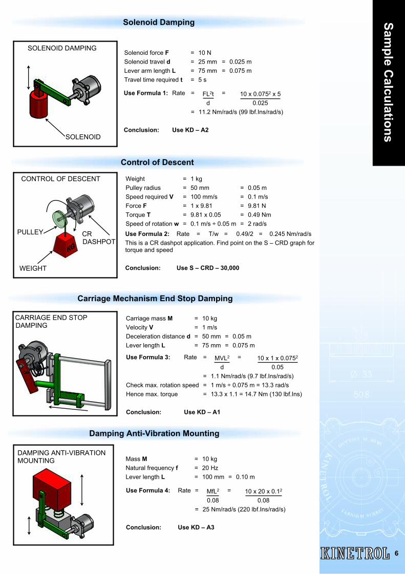
Control of Descent
Carriage Mechanism End Stop Damping
Damping Anti-Vibration Mounting
Mass M = 10 kgNatural frequency f = 20 HzLever length L = 100 mm = 0.10 m
Use Formula 4: Rate = MfL2 = 10 x 20 x 0.12
0.08 0.08= 25 Nm/rad/s (220 lbf.Ins/rad/s)
Conclusion: Use KD – A3
Weight = 1 kgPulley radius = 50 mm = 0.05 mSpeed required V = 100 mm/s = 0.1 m/sForce F = 1 x 9.81 = 9.81 NTorque T = 9.81 x 0.05 = 0.49 NmSpeed of rotation w = 0.1 m/s ÷ 0.05 m = 2 rad/sUse Formula 2: Rate = T/w = 0.49/2 = 0.245 Nm/rad/sThis is a CR dashpot application. Find point on the S – CRD graph fortorque and speed
Conclusion: Use S – CRD – 30,000
Solenoid force F = 10 NSolenoid travel d = 25 mm = 0.025 mLever arm length L = 75 mm = 0.075 mTravel time required t = 5 s
Use Formula 1: Rate = FL2t = 10 x 0.0752 x 5d 0.025
= 11.2 Nm/rad/s (99 lbf.Ins/rad/s)
Conclusion: Use KD – A2
Solenoid Damping
Carriage mass M = 10 kgVelocity V = 1 m/sDeceleration distance d = 50 mm = 0.05 mLever length L = 75 mm = 0.075 m
Use Formula 3: Rate = MVL2 = 10 x 1 x 0.0752
d 0.05= 1.1 Nm/rad/s (9.7 lbf.Ins/rad/s)
Check max. rotation speed = 1 m/s ÷ 0.075 m = 13.3 rad/sHence max. torque = 13.3 x 1.1 = 14.7 Nm (130 lbf.Ins)
Conclusion: Use KD – A1
SOLENOID DAMPING
SOLENOID
WEIGHT
CONTROL OF DESCENT
CRDASHPOT
PULLEY
CARRIAGE END STOPDAMPING
DAMPING ANTI-VIBRATIONMOUNTING
Spec
ial A
pplic
atio
ns
7
SPECIAL DASHPOT QUESTIONNAIREWhen standard dashpots are not suitable, special dampers (metal or plastic) may beoffered for high volume applications. To engineer a special unit the following informationis required:1 *Continuous rotation or reciprocating (state angle of travel) type.2 *Fixed rate or adjustable rate.3 *Unidirectional or bi-directional damping.4 Maximum operating speed.5 *Maximum operating torque (for strength).6 *Nominal torque and tolerance at specified speed and at 20°C (for damping rate).7 Maximum allowable frictional torque in each direction.8 *Maximum and minimum ambient temperatures.9 *Energy dissipation (watts).
10 *Typical cycle description and period between cycles/sequences11 *Maximum acceptable dimensions.12 Mounting arrangement, eg 2 or 4 lugs, clamped body, central or end flange.13 Drive arrangement, eg male or female, square or round with splines or keyway.14 Maximum side load.15 Maximum end load.16 Materials, eg zinc alloy, aluminium or acetal polymer.17 Surface finish, eg natural or painted.18 *Maximum weight.19 Any production test requirements.20 *Volume requirements.21 *Target unit price.22 Storage periods and conditions.
The data marked with an * is essential to initiate any study but all of the above data will berequired before a product can be produced.
KF-681 3/11
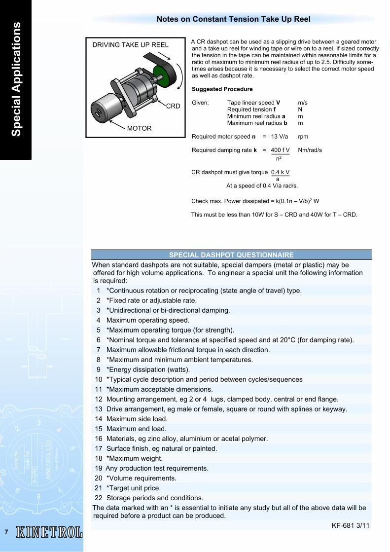
Notes on Constant Tension Take Up Reel
A CR dashpot can be used as a slipping drive between a geared motorand a take up reel for winding tape or wire on to a reel. If sized correctlythe tension in the tape can be maintained within reasonable limits for aratio of maximum to minimum reel radius of up to 2.5. Difficulty some-times arises because it is necessary to select the correct motor speedas well as dashpot rate.
Suggested Procedure
Given: Tape linear speed V m/sRequired tension f NMinimum reel radius a mMaximum reel radius b m
Required motor speed n = 13 V/a rpm
Required damping rate k = 400 f V Nm/rad/s n2
CR dashpot must give torque 0.4 k V a
At a speed of 0.4 V/a rad/s.
Check max. Power dissipated = k(0.1n – V/b)2 W
This must be less than 10W for S – CRD and 40W for T – CRD.
DRIVING TAKE UP REEL
MOTOR
CRD
Has an adjuster which permits any damping rate to beobtained within one of the following ranges. This range mustbe specified when ordering the dashpot.
A1: 0.8 to 10 lbf.ins/rad/s / 0.09 to 1.13 Nm/rad/s
A2: 10 to 100 lbf.ins/rad/s / 1.13 to 11.3 Nm/rad/s
A3: 100 to 1100 lbf.ins/rad/s / 11.3 to 124 Nm/rad/s
A4: 260 to 2600 lbf.ins/rad/s / 29 to 293 Nm/rad/s
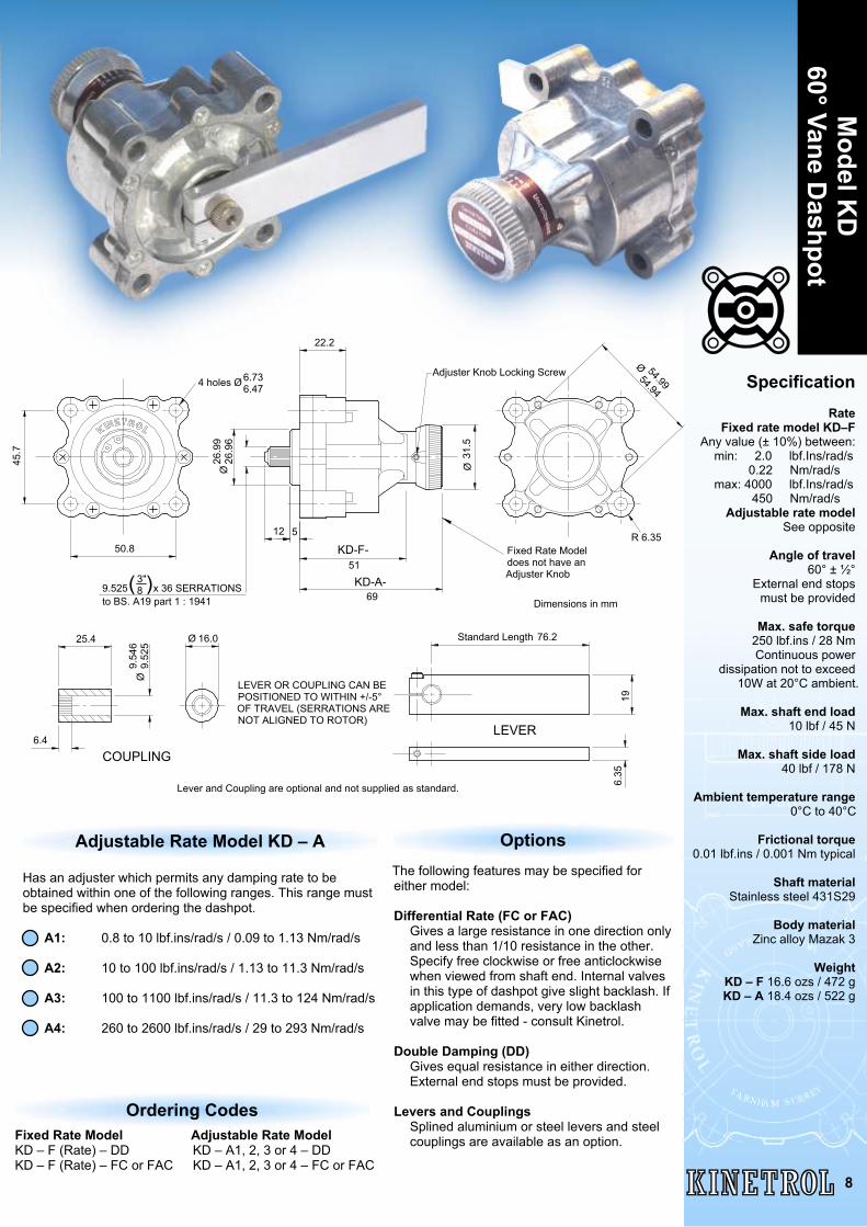
Adjustable Rate Model KD – A
SpecificationRate
Fixed rate model KD–FAny value (± 10%) between:
min: 2.0 lbf.Ins/rad/s 0.22 Nm/rad/s max: 4000 lbf.Ins/rad/s 450 Nm/rad/s
Adjustable rate modelSee opposite
Angle of travel60° ± ½°
External end stopsmust be provided
Max. safe torque250 lbf.ins / 28 NmContinuous power
dissipation not to exceed10W at 20°C ambient.
Max. shaft end load10 lbf / 45 N
Max. shaft side load40 lbf / 178 N
Ambient temperature range0°C to 40°C
Frictional torque0.01 lbf.ins / 0.001 Nm typical
Shaft materialStainless steel 431S29
Body materialZinc alloy Mazak 3
WeightKD – F 16.6 ozs / 472 gKD – A 18.4 ozs / 522 g
Fixed Rate ModelKD – F (Rate) – DDKD – F (Rate) – FC or FAC
Ordering CodesAdjustable Rate ModelKD – A1, 2, 3 or 4 – DDKD – A1, 2, 3 or 4 – FC or FAC
The following features may be specified foreither model:
Differential Rate (FC or FAC)Gives a large resistance in one direction onlyand less than 1/10 resistance in the other.Specify free clockwise or free anticlockwisewhen viewed from shaft end. Internal valvesin this type of dashpot give slight backlash. Ifapplication demands, very low backlashvalve may be fitted - consult Kinetrol.
Double Damping (DD)Gives equal resistance in either direction.External end stops must be provided.
Levers and CouplingsSplined aluminium or steel levers and steelcouplings are available as an option.
Options
50.8
45.7
6.736.47
R 6.35
54.9954.94
31.5
Ø
Adjuster Knob Locking Screw
22.2
26.9
926
.96
Ø
51
5
Fixed Rate Modeldoes not have anAdjuster Knob
12
4 holes Ø
KD-A-
Dimensions in mm
KD-F-
6.35
25.4
6.4
9.54
69.
525
Ø
16.0Ø
LEVER
COUPLING
76.2Standard Length
LEVER OR COUPLING CAN BEPOSITIONED TO WITHIN +/-5°OF TRAVEL (SERRATIONS ARENOT ALIGNED TO ROTOR)
Ø
19
to BS. A19 part 1 : 19419.525 x 36 SERRATIONS
3"8( )
69
Model K
D60° Vane D
ashpot
8
Lever and Coupling are optional and not supplied as standard.
Mod
el L
A21
5° V
ane
Das
hpot
9
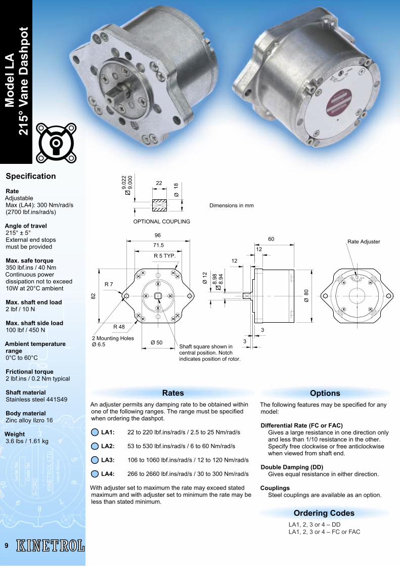
Specification
RateAdjustableMax (LA4): 300 Nm/rad/s(2700 lbf.ins/rad/s)
Angle of travel215° ± 5°External end stopsmust be provided
Max. safe torque350 lbf.ins / 40 NmContinuous powerdissipation not to exceed10W at 20°C ambient
Max. shaft end load2 lbf / 10 N
Max. shaft side load100 lbf / 450 N
Ambient temperaturerange0°C to 60°C
Frictional torque2 lbf.ins / 0.2 Nm typical
Shaft materialStainless steel 441S49
Body materialZinc alloy Ilzro 16
Weight3.6 lbs / 1.61 kg
The following features may be specified for anymodel:
Differential Rate (FC or FAC)Gives a large resistance in one direction onlyand less than 1/10 resistance in the other.Specify free clockwise or free anticlockwisewhen viewed from shaft end.
Double Damping (DD)Gives equal resistance in either direction.
CouplingsSteel couplings are available as an option.
Options
LA1, 2, 3 or 4 – DDLA1, 2, 3 or 4 – FC or FAC
Ordering Codes
An adjuster permits any damping rate to be obtained withinone of the following ranges. The range must be specifiedwhen ordering the dashpot.
LA1: 22 to 220 lbf.ins/rad/s / 2.5 to 25 Nm/rad/s
LA2: 53 to 530 lbf.ins/rad/s / 6 to 60 Nm/rad/s
LA3: 106 to 1060 lbf.ins/rad/s / 12 to 120 Nm/rad/s
LA4: 266 to 2660 lbf.ins/rad/s / 30 to 300 Nm/rad/s
With adjuster set to maximum the rate may exceed statedmaximum and with adjuster set to minimum the rate may beless than stated minimum.
Rates
2 Mounting HolesØ 6.5
Rate Adjuster
80Ø
6071.5
96
R 5 TYP.
82
R 7
R 48
Ø 50Shaft square shown incentral position. Notchindicates position of rotor.
12
3
3
12
12
8.98
8.94
OPTIONAL COUPLING
Dimensions in mm
2218
Ø
9.02
29.
000
Ø
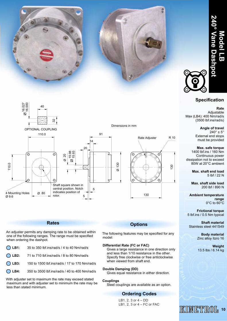
Model LB
240° Vane Dashpot
10
The following features may be specified for anymodel:
Differential Rate (FC or FAC)Gives a large resistance in one direction onlyand less than 1/10 resistance in the other.Specify free clockwise or free anticlockwisewhen viewed from shaft end.
Double Damping (DD)Gives equal resistance in either direction.
CouplingsSteel couplings are available as an option.
Options
LB1, 2, 3 or 4 – DDLB1, 2, 3 or 4 – FC or FAC
Ordering Codes
An adjuster permits any damping rate to be obtained withinone of the following ranges. The range must be specifiedwhen ordering the dashpot.
LB1: 35 to 350 lbf.ins/rad/s / 4 to 40 Nm/rad/s
LB2: 71 to 710 lbf.ins/rad/s / 8 to 80 Nm/rad/s
LB3: 150 to 1500 lbf.ins/rad/s / 17 to 170 Nm/rad/s
LB4: 350 to 3500 lbf.ins/rad/s / 40 to 400 Nm/rad/s
With adjuster set to maximum the rate may exceed statedmaximum and with adjuster set to minimum the rate may beless than stated minimum.
Rates
Specification
RateAdjustable
Max (LB4): 400 Nm/rad/s(3500 lbf.ins/rad/s)
Angle of travel240° ± 5°
External end stopsmust be provided
Max. safe torque1400 lbf.ins / 160 Nm
Continuous powerdissipation not to exceed
80W at 20°C ambient
Max. shaft end load5 lbf / 22 N
Max. shaft side load200 lbf / 890 N
Ambient temperaturerange
0°C to 60°C
Frictional torque5 lbf.ins / 0.5 Nm typical
Shaft materialStainless steel 441S49
Body materialZinc alloy Ilzro 16
Weight13.5 lbs / 6.14 kg
130
R 10
130
Rate Adjuster
130
Ø
91
14
20
5
5
15.9
815
.93
20Ø
110.0
110.
0
80Ø4 Mounting HolesØ 9.6
Shaft square shown incentral position. Notchindicates position ofrotor.
40
32
16.0
2716
.000
Dimensions in mmOPTIONAL COUPLING
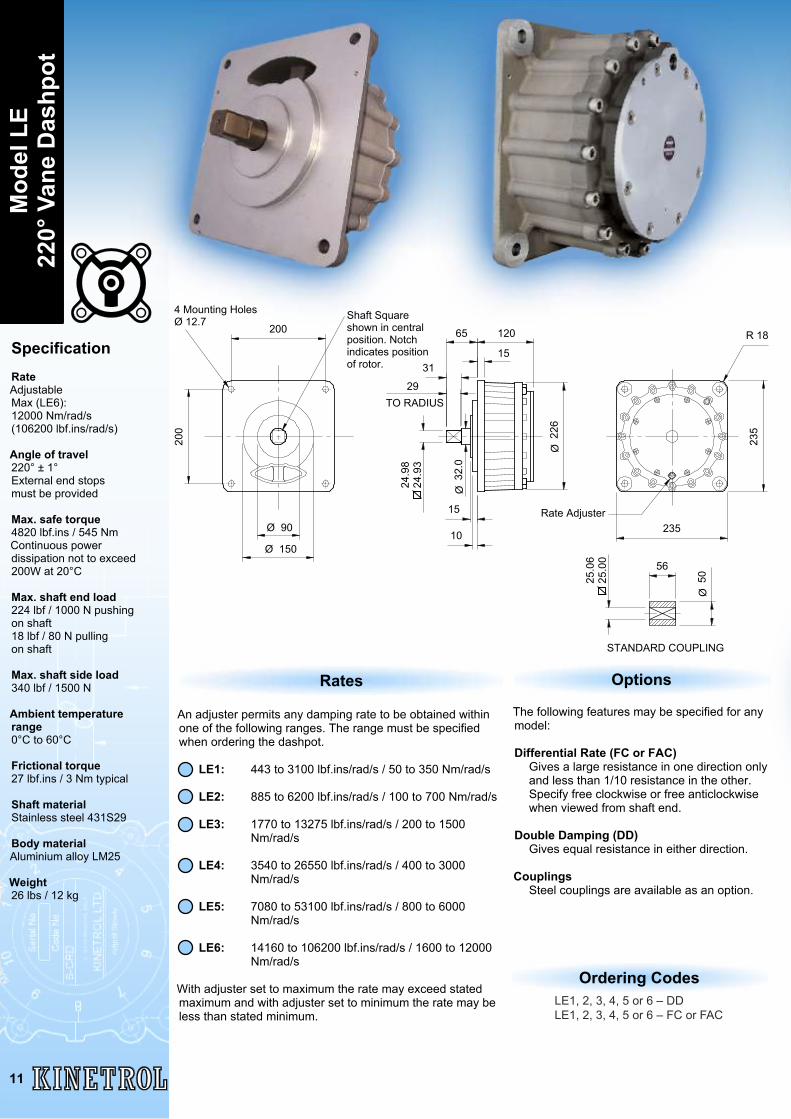
SpecificationRateAdjustableMax (LE6):12000 Nm/rad/s(106200 lbf.ins/rad/s)
Angle of travel220° ± 1°External end stopsmust be provided
Max. safe torque4820 lbf.ins / 545 NmContinuous powerdissipation not to exceed200W at 20°C
Max. shaft end load224 lbf / 1000 N pushingon shaft18 lbf / 80 N pullingon shaft
Max. shaft side load340 lbf / 1500 N
Ambient temperaturerange0°C to 60°C
Frictional torque27 lbf.ins / 3 Nm typical
Shaft materialStainless steel 431S29
Body materialAluminium alloy LM25
Weight26 lbs / 12 kg
The following features may be specified for anymodel:
Differential Rate (FC or FAC)Gives a large resistance in one direction onlyand less than 1/10 resistance in the other.Specify free clockwise or free anticlockwisewhen viewed from shaft end.
Double Damping (DD)Gives equal resistance in either direction.
CouplingsSteel couplings are available as an option.
Options
LE1, 2, 3, 4, 5 or 6 – DDLE1, 2, 3, 4, 5 or 6 – FC or FAC
Ordering Codes
An adjuster permits any damping rate to be obtained withinone of the following ranges. The range must be specifiedwhen ordering the dashpot.
LE1: 443 to 3100 lbf.ins/rad/s / 50 to 350 Nm/rad/s
LE2: 885 to 6200 lbf.ins/rad/s / 100 to 700 Nm/rad/s
LE3: 1770 to 13275 lbf.ins/rad/s / 200 to 1500 Nm/rad/s
LE4: 3540 to 26550 lbf.ins/rad/s / 400 to 3000 Nm/rad/s
LE5: 7080 to 53100 lbf.ins/rad/s / 800 to 6000 Nm/rad/s
LE6: 14160 to 106200 lbf.ins/rad/s / 1600 to 12000 Nm/rad/s
With adjuster set to maximum the rate may exceed statedmaximum and with adjuster set to minimum the rate may beless than stated minimum.
Rates
11
Mod
el L
E22
0° V
ane
Das
hpot
235
235
226
Ø200
200
Ø 90
Ø 15010
15
12065
15
TO RADIUS
R 18
Rate Adjuster
Shaft Squareshown in centralposition. Notchindicates positionof rotor.
4 Mounting HolesØ 12.7
24.9
824
.93
32.0
Ø
31
29
25.0
625
.00
STANDARD COUPLING
50Ø
56
12
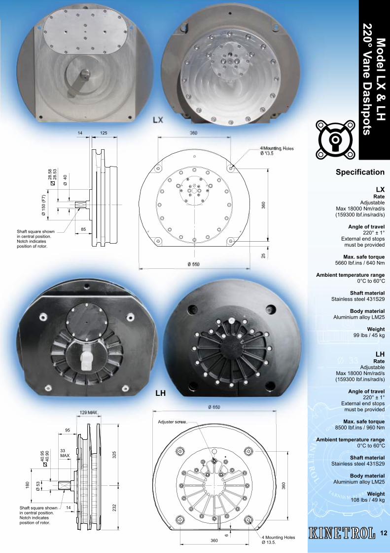
Model LX &
LH220° Vane D
ashpotsLX
Specification
LXRate
AdjustableMax 18000 Nm/rad/s(159300 lbf.ins/rad/s)
Angle of travel220° ± 1°
External end stopsmust be provided
Max. safe torque5660 lbf.ins / 640 Nm
Ambient temperature range0°C to 60°C
Shaft materialStainless steel 431S29
Body materialAluminium alloy LM25
Weight99 lbs / 45 kg
LHRate
AdjustableMax 18000 Nm/rad/s(159300 lbf.ins/rad/s)
Angle of travel220° ± 1°
External end stopsmust be provided
Max. safe torque8500 lbf.ins / 960 Nm
Ambient temperature range0°C to 60°C
Shaft materialStainless steel 431S29
Body materialAluminium alloy LM25
Weight108 lbs / 49 kg
25550Ø
360
360
Ø 1
50 (F
7)
85
40Ø
28.5
828
.53
14 125
4 Mounting HolesØ 13.5
Shaft square shownin central position.Notch indicatesposition of rotor.
360
325
232
129 MAX.
360
650Ø
95
33MAX
14
6
180
Adjuster screw.
4 Mounting HolesØ 13.5.
Shaft square shownin central position.Notch indicatesposition of rotor.
53Ø
40.9
540
.90
LH
1
SPEED - Rev / min.
1
2
46
0.1
8
0.01
10
LBF IN.
SPEED - Radians / sec
NmTORQUE
25
0.1
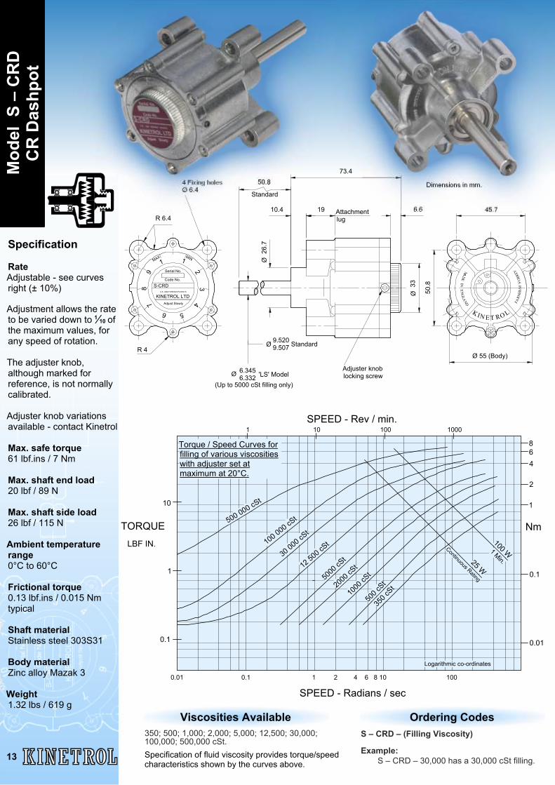
500 000 cSt
30 000 cSt
12 500 cSt
5000
cSt
2000
cSt
1000
cSt
500 c
St
350 c
St
Continuous Rating
100 W1 Min.25 W
100 000 cSt
Logarithmic co-ordinates
Torque / Speed Curves forfilling of various viscositieswith adjuster set atmaximum at 20°C.
0.01 0.1 1 2 4 6 8 10 100
1 10 100 1000
Specification
RateAdjustable - see curvesright (± 10%)
Adjustment allows the rateto be varied down to ofthe maximum values, forany speed of rotation.
The adjuster knob,although marked forreference, is not normallycalibrated.
Adjuster knob variationsavailable - contact Kinetrol
Max. safe torque61 lbf.ins / 7 Nm
Max. shaft end load20 lbf / 89 N
Max. shaft side load26 lbf / 115 N
Ambient temperaturerange0°C to 60°C
Frictional torque0.13 lbf.ins / 0.015 Nmtypical
Shaft materialStainless steel 303S31
Body materialZinc alloy Mazak 3
Weight1.32 lbs / 619 g
56
78
9
MAX1
MIN1
23
4 FARN
HAM
SU
RREY
NE
NG
LAND
IA
DE
M
K I E T RO LN
S-CRD
Serial No.
Code No.
U.K. AND FOREIGN PATENTS
Adjust Slowly
73.4
6.6
33Ø
Ø 55 (Body)
45.7
50.8
1910.4
50.8
Attachmentlug
26.7
Ø
Adjuster knoblocking screw
6.3456.332
4 Fixing holesØ 6.4
R 6.4
9.5209.507 Standard
Ø
StandardDimensions in mm.
'LS' Model
KINETROL LTD
R 4Ø
(Up to 5000 cSt filling only)
Ordering CodesS – CRD – (Filling Viscosity)
Example:S – CRD – 30,000 has a 30,000 cSt filling.
Mod
el S
– C
RD
CR
Das
hpot
13
Viscosities Available350; 500; 1,000; 2,000; 5,000; 12,500; 30,000;100,000; 500,000 cSt.Specification of fluid viscosity provides torque/speedcharacteristics shown by the curves above.
1∕10
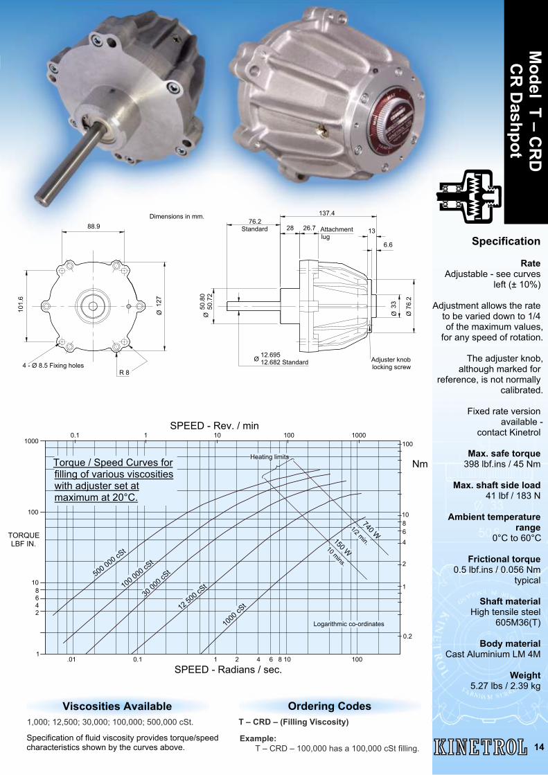
Specification
RateAdjustable - see curves
left (± 10%)
Adjustment allows the rateto be varied down to 1/4of the maximum values,
for any speed of rotation.
The adjuster knob,although marked for
reference, is not normallycalibrated.
Fixed rate versionavailable -
contact Kinetrol
Max. safe torque398 lbf.ins / 45 Nm
Max. shaft side load41 lbf / 183 N
Ambient temperaturerange
0°C to 60°C
Frictional torque0.5 lbf.ins / 0.056 Nm
typical
Shaft materialHigh tensile steel
605M36(T)
Body materialCast Aluminium LM 4M
Weight5.27 lbs / 2.39 kg
Ordering CodesT – CRD – (Filling Viscosity)
Example:T – CRD – 100,000 has a 100,000 cSt filling.
Model T – C
RD
CR
Dashpot
14
Ø Ø 7
6.2
101.
6
88.9
127
Ø
4 - Ø 8.5 Fixing holes
33
13
12.69512.682 Standard
50.8
050
.72
Ø
Adjuster knoblocking screw
Dimensions in mm.
Attachmentlug
76.2Standard
137.4
28 26.7
6.6
R 8
Ø
.01 0.1 1 2 4 6 8 10 1001
10
100
1000
SPEED - Radians / sec.
SPEED - Rev. / min0.1 1 10 100 1000
10
100
8
0.2
Nm
8642
Logarithmic co-ordinates
Heating limits
500 000 cSt
100 000 cSt
30 00
0 cSt
12 500 cSt
1000
cSt
740 W
1/2 min.150 W10 mins.
TORQUE LBF IN.
1
2
46
Torque / Speed Curves forfilling of various viscositieswith adjuster set atmaximum at 20°C.
Viscosities Available1,000; 12,500; 30,000; 100,000; 500,000 cSt.
Specification of fluid viscosity provides torque/speedcharacteristics shown by the curves above.
Mod
el Q
– C
RD
CR
Das
hpot
15
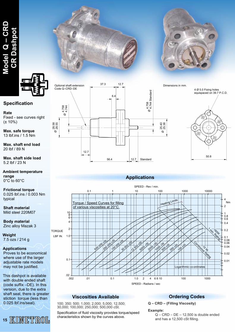
Specification
RateFixed - see curves right(± 10%)
Max. safe torque13 lbf.ins / 1.5 Nm
Max. shaft end load20 lbf / 89 N
Max. shaft side load5.2 lbf / 23 N
Ambient temperaturerange0°C to 60°C
Frictional torque0.025 lbf.ins / 0.003 Nmtypical
Shaft materialMild steel 220M07
Body materialZinc alloy Mazak 3
Weight7.5 ozs / 214 g
ApplicationsProves to be economicalwhere use of the largeradjustable rate modelsmay not be justified.
This dashpot is availablewith double ended shaft(code suffix –DE). In thisversion, due to the extrashaft seal, there is greaterstiction torque (less than0.025 lbf.ins/seal).
56.4 12.7
4.75
84.
744
Sta
ndar
d
25.4
025
.38
Ø
12.737.3
6.4
28.5
828
.55
Ø
50.8
4 Ø 5.0 Fixing holesequispaced on 39.7 P.C.D.
12.7
Optional shaft extensionCode Q–CRD–DE
4.75
84.
744
Ø
Standard
Dimensions in mm.
Ø
SPEED - Radians / sec
Nm
LBF IN.
TORQUE
0.01
.002 .01 0.1 1.0 2 4 6 8 10 100 1000
0.1
1.0
2
468
10
0.1 1 10 100 1000
4
.02
Logarithmic co-ordinates
5000
cSt
10000
Continuous Rating
15 W
160W1 min. Rating
SPEED - Rev / min.
Heating Limits
500 000 cSt
250 0
00 cS
t
100 000 cSt
30 000 cSt
12 500 cSt
100 cSt
350 cSt
500 cSt
1000
cSt
2000
cSt
0.60.81
2
0.4
0.02
0.040.060.080.1
0.2
Torque / Speed Curves for fillingof various viscosities at 20°C.
Ordering CodesQ – CRD – (Filling Viscosity)
Example:Q – CRD – DE – 12,500 is double endedand has a 12,500 cSt filling.
Applications
Viscosities Available100; 350; 500; 1,000; 2,000; 5,000; 12,500;30,000; 100,000; 250,000; 500,000 cSt.Specification of fluid viscosity provides torque/speedcharacteristics shown by the curves above.
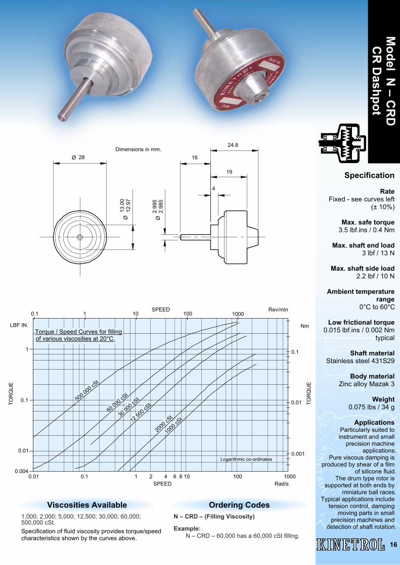
Ordering CodesN – CRD – (Filling Viscosity)
Example:N – CRD – 60,000 has a 60,000 cSt filling.
Specification
RateFixed - see curves left
(± 10%)
Max. safe torque3.5 lbf.ins / 0.4 Nm
Max. shaft end load3 lbf / 13 N
Max. shaft side load2.2 lbf / 10 N
Ambient temperaturerange
0°C to 60°C
Low frictional torque0.015 lbf.ins / 0.002 Nm
typical
Shaft materialStainless steel 431S29
Body materialZinc alloy Mazak 3
Weight0.075 lbs / 34 g
ApplicationsParticularly suited toinstrument and small
precision machineapplications.
Pure viscous damping isproduced by shear of a film
of silicone fluid. The drum type rotor is
supported at both ends byminiature ball races.
Typical applications includetension control, damping
moving parts in smallprecision machines and
detection of shaft rotation.
Model N
– CR
DC
R D
ashpot
16
Viscosities Available1,000; 2,000; 5,000; 12,500; 30,000; 60,000;500,000 cSt.Specification of fluid viscosity provides torque/speedcharacteristics shown by the curves above.
24.8
19
16
4
2.99
52.
985
Ø28Ø
13.0
012
.97
Ø
Dimensions in mm.
SPEED0.01 0.1 1 2 4 6 8 10 100 1000
TOR
QU
E
LBF IN.
TOR
QU
E
Rad/s
Nm
0.1 1 10 100
0.1
SPEED Rev/min
0.004
0.1
1
0.01
1000
0.001
0.01
Logarithmic co-ordinates
1000
cSt
500 000 cSt
60 000 cSt
12 50
0 cSt
2000
cSt30
000 c
St
Torque / Speed Curves for fillingof various viscosities at 20°C.
1 10 100 1000
0.1 1 2 4 6 8 10 100 1000
LBF. IN
SPEED
Nm
TOR
QU
E
SPEED
TOR
QU
E
100
0.1
1
2
4
68
10
0.02
0.1
2
4
6
8
1
Rad/s
Rev/min
500 000 cSt
1000 cSt2000 cSt
5000 cSt
12 50
0 cSt
30 000 cSt100 000 cS
t
250 000 cSt
Logarithmic co-ordinates
Continuous rating 10 W
60 000 cSt
Torque / Speed Curves for fillingof various viscosities at 20°C.
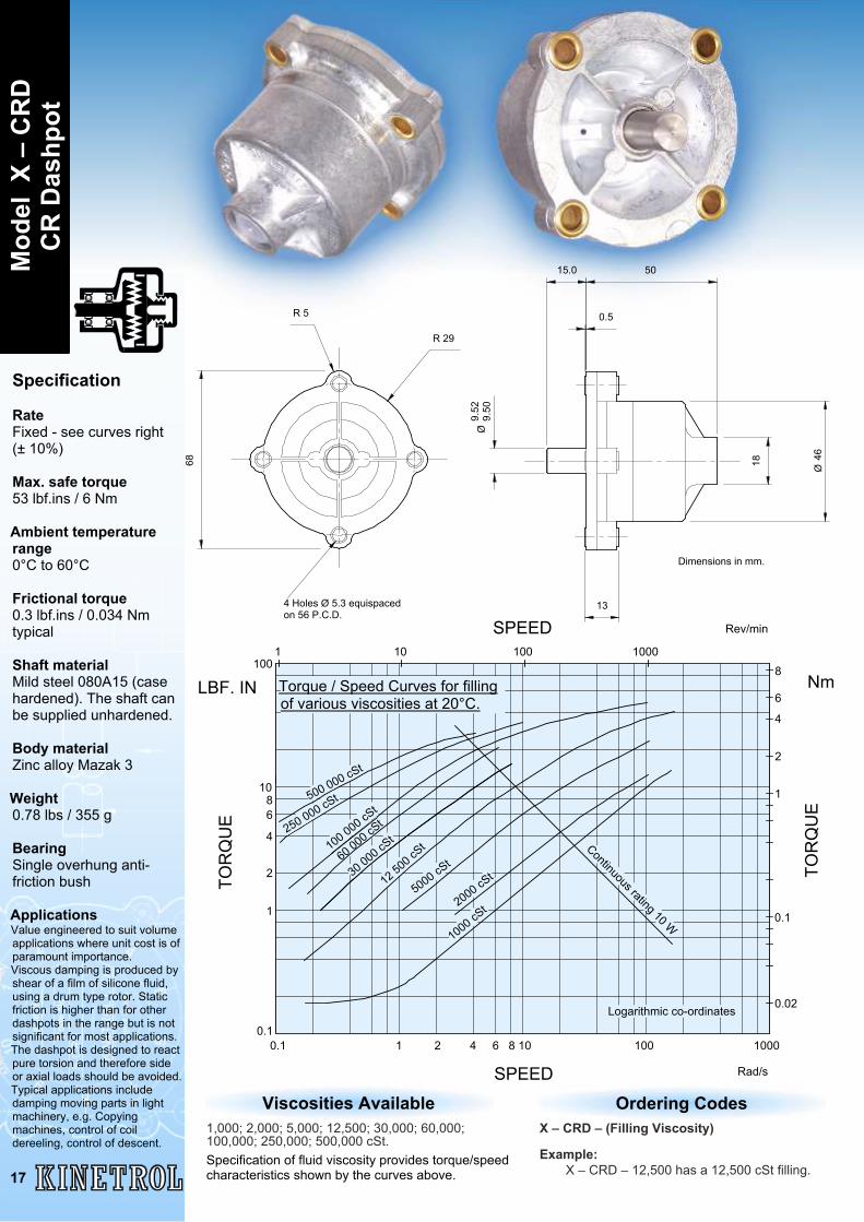
Specification
RateFixed - see curves right(± 10%)
Max. safe torque53 lbf.ins / 6 Nm
Ambient temperaturerange0°C to 60°C
Frictional torque0.3 lbf.ins / 0.034 Nmtypical
Shaft materialMild steel 080A15 (casehardened). The shaft canbe supplied unhardened.
Body materialZinc alloy Mazak 3
Weight0.78 lbs / 355 g
BearingSingle overhung anti-friction bush
ApplicationsValue engineered to suit volumeapplications where unit cost is ofparamount importance.Viscous damping is produced byshear of a film of silicone fluid,using a drum type rotor. Staticfriction is higher than for otherdashpots in the range but is notsignificant for most applications.The dashpot is designed to reactpure torsion and therefore sideor axial loads should be avoided.Typical applications includedamping moving parts in lightmachinery, e.g. Copyingmachines, control of coildereeling, control of descent.
Ordering CodesX – CRD – (Filling Viscosity)
Example:X – CRD – 12,500 has a 12,500 cSt filling.
46Ø
50
0.5
15.0
68
R 29
R 5
4 Holes Ø 5.3 equispacedon 56 P.C.D.
9.52
9.50
Ø
13
Dimensions in mm.
18
Mod
el X
– C
RD
CR
Das
hpot
17
Viscosities Available1,000; 2,000; 5,000; 12,500; 30,000; 60,000;100,000; 250,000; 500,000 cSt.Specification of fluid viscosity provides torque/speedcharacteristics shown by the curves above.
Bespoke D
ashpots
18
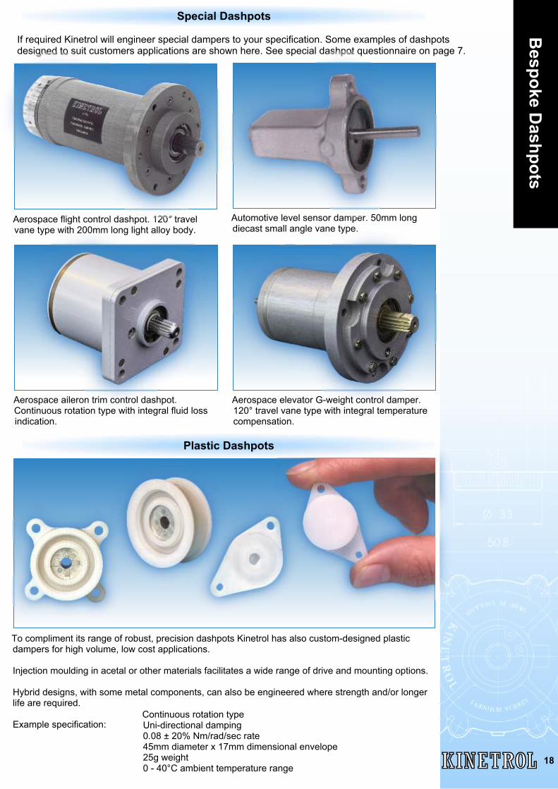
If required Kinetrol will engineer special dampers to your specification. Some examples of dashpotsdesigned to suit customers applications are shown here. See special dashpot questionnaire on page 7.
Automotive level sensor damper. 50mm longdiecast small angle vane type.
Aerospace flight control dashpot. 120° travelvane type with 200mm long light alloy body.
Aerospace elevator G-weight control damper.120° travel vane type with integral temperaturecompensation.
Special Dashpots
Aerospace aileron trim control dashpot.Continuous rotation type with integral fluid lossindication.
To compliment its range of robust, precision dashpots Kinetrol has also custom-designed plasticdampers for high volume, low cost applications.
Injection moulding in acetal or other materials facilitates a wide range of drive and mounting options.
Hybrid designs, with some metal components, can also be engineered where strength and/or longerlife are required.
Example specification:Continuous rotation typeUni-directional damping0.08 ± 20% Nm/rad/sec rate45mm diameter x 17mm dimensional envelope25g weight0 - 40°C ambient temperature range
Plastic Dashpots

Kinetrol Ltd, Trading Estate, Farnham, Surrey, GU9 9NU, EnglandTelephone: +44 (0)1252 733838 Fax: +44 (0)1252 713042
www.kinetrol.com e-mail: [email protected] KF
- 72
OC
T/17
Distributed by:
AustriaDietrich Schwabe GmbHEinsteinstrasse 26D-64859 EppertshausenDeutschlandTel - (49) 6071 922290Fax - (49) 6071 9222911email - [email protected]
BelgiumNV Prodim SAAv. Antoon Van Osslaan 1/20B-1120 Neder-over-HeembeekTel - 02 726 3300Fax - 02 726 3633email - [email protected]
ChinaShanghai KinetrolControl Equipment Co. Ltd.Building 112 (G1)456 Dieqiao Road, Kangqiao TownPudong New DistrictShanghai 201315Tel - 21 5431 2366Fax - 21 5431 2399email - [email protected]
FranceKinetrol SarlActigone 3 - BP1028 - MEYTHET74960 ANNECYTel - 0450 22 19 26Fax - 0450 22 31 54email - [email protected]
GermanyDietrich Schwabe GmbHEinsteinstrasse 26, D-64859EppertshausenTel - 6071 922290Fax - 6071 9222911email - [email protected]
ItalyBellkin S.R.L.Via Trieste, 60/E20821 - Meda - MBTel - 0362 330269Fax - 0362 327069email - [email protected]
JapanSankyo Shoji Co. Ltd3-2-13 Kitahama, Chuo-ku,Osaka-shi, Osaka, 541-0041Tel - 81 6 6202 8121Fax - 81 6 6202 8127email - [email protected]
MexicoERCO Equipos Refacciones yControles de OccidenteS.A. de C.V.No. 904 Fracc Zenzontle. 8 de JulioC.P. 44910, Guadalajara, JaliscoTel - 33 3810 4714 - 33 3812 2617 - 33 3812 4428Fax - 33 3810 1080email - [email protected]
PolandDietrich Schwabe GmbHEinsteinstrasse 26D-64859 EppertshausenDeutschlandTel - (49) 6071 922290Fax - (49) 6071 9222911email - [email protected]
SpainKinetrol SLUC/Salmeron, 25008226-Terrassa, BarcelonaTel - 93 7862496Fax - 93 7851368email - [email protected]
SwitzerlandDietrich Schwabe GmbHEinsteinstrasse 26D-64859 EppertshausenDeutschlandTel - (49) 6071 922290Fax - (49) 6071 9222911email - [email protected]
USA - KansasEfdyn Incorporated7734 East 11th Street, TulsaOklahoma 74112-5718Tel - 918 838 1170Fax - 918 835 3334email - [email protected]
USA - OhioOhio Fluid Power Inc.3660 Center Road#305 Brunswick, OH 44212Tel - 440 238 5656Fax - 440 238 1466email - [email protected]
USA - OklahomaEfdyn Incorporated7734 East 11th Street, TulsaOklahoma 74112-5718Tel - 918 838 1170Fax - 918 835 3334email - [email protected]
Worldwide Distribution
All other locations please contact Kinetrol at the address below
Kinetrol is a registered trade mark Copyright 2015 Kinetrol Ltd