Rotary Cam Switches - Amazon Web Services
34
K1 visit www.sprecherschuh.com/ecatalog for the most up to date information SSNA2014 K Rotary Cam Switches Rotary Cam Switches Series L2 Rotary Cam Switches ................................................................. K2 Handle Assemblies................................................................................. K6 Accessories ......................................................................................... K10 Circuit Diagrams .................................................................................. K11 Technical Information........................................................................... K14 Dimensions.......................................................................................... K19 Series R-Line Rotary Cam Switches......................................................... K22 Handles and Accessories ..................................................................... K25 Circuit Diagrams .................................................................................. K28 Technical Information........................................................................... K29 Dimensions.......................................................................................... K30 REVISED February 2015 This section has been revised since publication. Catalog Numbers not shown have been obsoleted.
Transcript of Rotary Cam Switches - Amazon Web Services

K1visit www.sprecherschuh.com/ecatalog for the most up to date informationSSNA2014
K
Rot
ary
Cam
Sw
itche
s
Rotary Cam Switches
Series L2 Rotary Cam Switches ................................................................. K2Handle Assemblies................................................................................. K6Accessories ......................................................................................... K10Circuit Diagrams .................................................................................. K11Technical Information ........................................................................... K14Dimensions .......................................................................................... K19
Series R-Line Rotary Cam Switches ......................................................... K22Handles and Accessories ..................................................................... K25Circuit Diagrams .................................................................................. K28Technical Information ........................................................................... K29Dimensions .......................................................................................... K30
REVISED February 2015This section has been revised since publication. Catalog Numbers not shown have been obsoleted.

K
L2
Rota
ry C
am S
witc
hes
K2visit www.sprecherschuh.com/ecatalog for the most up to date information SSNA2014
Series L2 Rotary Cam Switches
Attractive design, reliable operation and high quality for any application up to 25 Amps
Sprecher + Schuh’s comprehensive line of L2 rotary cam switches are available for all control and load applications up to 25 amps. The line is modular and has many convenience and safety features. A well thought out ordering system provides many standard and nonstandard configurations, that are many times available off the shelf.
Any switch configuration…Two frame sizes provide control and load switching up to 25 amps. Both frame sizes are available in panel mount and base mount for total flex-ibility. A wide range of switching configurations are offered from stock and in many cases custom switches can be fabricated to order.
…For any applicationL2 control and load switches are UL listed, CSA approved and comply with the most important international standards for use as:
• Control switches - for process control, making and breaking circuits and as instrument selector switches.
• Motor switches - as ON/OFF and reversing switches.
• Multi-position load switches - for the step control of loads such as heat-ers and furnaces.
• Motor load disconnect switches - for safely isolating circuits during repair and maintenance.
• Emergency OFF switches - for isolating circuits in case of danger or emergency situations. Can be equipped for locking in the OFF position.
Safety and qualityThe L2’s sturdy design incorporates a positive switching action with a clearly
designed switching point. Switch bod-ies are touch-safe (IP20) and manufac-tured from self-extinguishing materials corresponding to Class UL 94 V0. All control knobs and shafts are spray proof and dust proof to IP65.
Modular and flexibleThe same switch handle assemblies and shaft extension systems are used for both our L2 control switches and L7 disconnect switches. This reduces in-ventory, simplifies stocking and allows you to put together the ideal switch for your application quickly and easily.
Simple assembly and fast installationShaft extensions and door interlocks snap-on quickly without tools, sav-ing time during assembly. Captive terminals are shipped open and are totally accessible regardless of whether the switch is base mounted or panel mounted. Screwdriver guides and clear terminal markings reduce wiring mistakes and speed installation.
In addition, most switch handle as-semblies are available with either screw fixing or the new central nut mounting system for total flexibility.
To learn the basic differences between control, load and fusible disconnect switches and how to apply them, ask your Sprecher + Schuh representative for publication no. Tech-LMSD.
®
TIP!Manual Switching Devices:
Control, Load or Fusible Disconnect Switches…
Which is Best For Your Application?
Application Data
Typical Control SwitchTypical Load Break Switch
Typical Fusible Disconnect Switch
Industrial DesignForum Hannover
Prize forgood design
REVISED April 2016This section has been revised since publication. Catalog Numbers not shown have been obsoleted.

K
L2
Rota
ry C
am S
witc
hes
K3visit www.sprecherschuh.com/ecatalog for the most up to date informationSSNA2014
Discount Schedule K1
REVISED
How to order L2 control and load switchesA complete L2 switch is ordered with just two catalog numbers. The first number specifies the switch body and the second specifies the switch handle assembly. All L2 switch bodies come standard with a shaft and mounting screws for the switch handle assembly. Accessories such as shaft extensions and enclosures are ordered separately.
First determine the switch body you need from pages K4 through K5. Then turn to page K6 to choose a switch handle assembly. If neces-sary, turn to page K8 and K9 to determine the type and length of shaft extension you require.
Switch Handle Assemblies - page K6
Switch Body Assemblies - pages K4 through K5
A comprehensive family of switchesThe L2 line is part of an entire family of control and load switches available from Sprecher + Schuh.
For specialized switching requirements or large ampere applications up to 40A (@600V), our R-Line Rotary Cam Switches offer a broad selection and rugged quality. See the next chapter in this section entitled “R-Line Rotary Cam Switches” (K22) for ordering information.
Our modular L7 disconnect switches are rated to 100 amps for motor, loads and disconnect switching. They share many of the same components with the L2 line. A complete descrip-tion and ordering information can be found in Section L of this catalog.
Rounding out our selection of “man-machine interfaces,” Sprecher + Schuh also offers a broad selection of 22mm pilot devices. See “Section H” in this catalog for ordering information.
L7 Line
R-Line
Rotary Cam SwitchesSeries L2

K
L2
Rota
ry C
am S
witc
hes
K4visit www.sprecherschuh.com/ecatalog for the most up to date information SSNA2014
Discount Schedule K1
REVISED Rotary Cam SwitchesSeries L2
Switch Body Description Circuit Diagram Number
(▲)
Switch Body Catalog Number & PriceSwitch HandleCodeFunction Switch
Angle
Poles/ Switch Wafers
Panel Mount Base Mount
12 Amp 16 Amp 20 Amp 25 Amp 12 Amp 16 Amp 20 Amp 25 AmpLE2-12-▲ LE2-16-▲ LE2-20-▲ LE2-25-▲ LA2-12-▲ LA2-16-▲ LA2-20-▲ LA2-25-▲
ON - OFF
90°
1 / 1 1751 28.00 31.00 47.00 56.50 34.50 39.75 54.50 65.50
175175I
2 / 1 1752 34.00 41.00 56.50 69.00 41.00 47.50 64.00 76.503 / 2 1753 45.00 55.00 74.50 89.00 48.50 61.50 82.00 97.004 / 2 1754 51.50 62.50 84.00 100.00 58.00 69.00 92.00 107.005 / 3 1755 62.00 76.50 102.00 120.00 69.00 83.00 109.00 128.006 / 3 1756 68.50 84.00 111.00 131.00 75.00 90.50 119.00 138.00
90°
1 / 1 1781 28.00 31.00 47.00 56.50 34.50 39.75 54.50 65.50178178I
2 / 1 1782 34.00 41.00 56.50 69.00 41.00 47.50 64.00 72.003 / 2 1783 45.00 55.00 74.50 89.00 51.50 61.50 82.00 97.004 / 2 1784 51.50 62.50 84.00 100.00 57.00 69.00 92.00 107.00
Double Throw
45°
1 / 1 2251 34.00 41.00 56.50 69.00 41.00 47.50 64.00 72.00
2252 / 2 2252 51.50 62.50 84.00 100.00 58.00 69.00 92.00 107.003 / 3 2253 68.50 84.00 111.00 131.004 / 4 2254 86.00 106.00 136.00 162.005 / 5 2255 113.00 22.55 178.00 204.00
60°
1 / 1 2501 34.00 41.00 56.50 69.00
2502 / 2 2502 51.50 62.50 84.00 100.003 / 3 2503 68.50 84.00 111.00 131.004 / 4 2504 86.00 106.00 139.00 162.005 / 5 2505 113.00 137.00 178.00 204.00
45°325
325R
1 / 1 3251 34.00 41.00 56.50 69.00 41.00 47.50 64.002 / 2 3252 51.00 62.50 84.00 100.00 58.00 69.00 92.003 / 3 3253 68.50 84.00 111.00 131.00 75.00 90.50 119.004 / 4 3254 86.00 106.00 139.00 162.00 92.00 112.00 147.00
60° 350
1 / 1 3501 34.00 41.00 56.50 69.002 / 2 3502 51.00 62.50 84.00 100.003 / 3 3503 68.50 84.00 111.00 131.004 / 4 3504 86.00 106.00 139.00 162.00
90° 375
1 / 1 3751 34.00 41.00 56.50 69.002 / 2 3752 51.00 62.50 84.00 100.003 / 3 3753 68.50 84.00 111.00 131.004 / 4 3754 86.00 106.00 139.00 162.00
45° 3251 /1 3261 34.00 41.00 56.50 69.002 / 2 3262 51.00 62.50 84.00 100.003 / 3 3263 68.50 84.00 111.00 131.00
Ordering Instructions● Specify Switch Body catalog# from top of column.● Replace (▲) with Circuit Diagram Number (refer to
pages K11-K13 for diagrams).
● Select Switch Handle Assembly from pages K6 using Switch Handle Code above (switch handles sold separately).
● Example: LE2-16-1753 (Switch Body)LFS2-A-4-175 (Switch Handle Assembly)

K
L2
Rota
ry C
am S
witc
hes
K5visit www.sprecherschuh.com/ecatalog for the most up to date informationSSNA2014
Discount Schedule K1
REVISED Rotary Cam SwitchesSeries L2
Switch Body Description Circuit Diagram Number
(▲)
Switch Body Catalog Number & PriceSwitch HandleCodeFunction Switch
Angle
Poles/ Switch Wafers
Panel Mount Base Mount
12 Amp 16 Amp 20 Amp 25 Amp 12 Amp 16 Amp 20 Amp 25 AmpLE2-12-▲ LE2-16-▲ LE2-20-▲ LE2-25-▲ LA2-12-▲ LA2-16-▲ LA2-20-▲ LA2-25-▲
3 Position
60° 4501 / 2 4501 45.00 55.00 74.50 89.002 / 3 4502 68.50 84.00 111.00 131.003 / 5 4503 106.00 129.00 168.00 193.00
3 Position (with OFF)
45° 5251 / 1 5251 34.00 41.00 56.50 69.002 / 2 5252 51.00 62.50 84.00 100.003 / 3 5253 68.50 84.00 111.00 131.00
4 Position
60° 4511 /2 4511 51.00 61.50 84.00 100.002 / 4 4512 86.00 106.00 139.00 162.003 / 6 4513 130.00 159.00 205.00 235.00
4 Position (with OFF)
45° 5261 / 2 5261 45.00 55.00 74.50 89.00 52.00 61.50 82.00 97.002 / 3 5262 68.50 84.00 111.00 131.003 / 5 5263 106.00 129.00 168.00 193.00
5 Position (with OFF)
45° 5271 / 2 5271 51.00 62.50 84.00 100.00 58.00 69.00 92.00 107.002 / 4 5272 86.00 106.00 139.00 162.003 / 6 5273 130.00 159.00 205.00 235.00
6 Position
60° 1 / 3 4531 68.50 84.00 111.00 131.00 453
6 Position (with OFF)
60° 5531 /3 5531 62.00 76.50 102.00 120.002 / 5 5532 113.00 137.00 178.00 204.003 / 8 5533 158.00 194.00 251.00 286.00
Ordering Instructions● Specify Switch Body catalog# from top of column.● Replace (▲) with Circuit Diagram Number (refer to
pages K11-K13 for diagrams).
● Select Switch Handle Assembly from pages K6 using Switch Handle Code above (switch handles sold separately).
● Example: LE2-16-1753 (Switch Body)LFS2-A-4-175 (Switch Handle Assembly)

K
L2
Rota
ry C
am S
witc
hes
K5.1visit www.sprecherschuh.com/ecatalog for the most up to date informationSSNA2014
Discount Schedule K1
REVISED Rotary Cam SwitchesSeries L2
Ordering Instructions● Specify Switch Body catalog# from top of column.● Replace (▲) with Circuit Diagram Number (refer to
pages K11-K13 for diagrams).
● Select Switch Handle Assembly from pages K6 using Switch Handle Code above (switch handles sold separately).
● Example: LE2-16-1753 (Switch Body)LFS2-A-4-175 (Switch Handle Assembly)
Switch Body Description Circuit Diagram Number
(▲)
Switch Body Catalog Number & PriceSwitch HandleCodeFunction Switch
Angle
Poles/ Switch Wafers
Panel Mount Base Mount
12 Amp 16 Amp 20 Amp 25 Amp 12 Amp 16 Amp 20 Amp 25 AmpLE2-12-▲ LE2-16-▲ LE2-20-▲ LE2-25-▲ LA2-12-▲ LA2-16-▲ LA2-20-▲ LA2-25-▲
START - STOP
45° 1 / 1 9251 34.00 41.00 56.50 69.00 41.00 47.50 64.00 76.50 925
REVERSING
45 ° 3 / 3 7303 62.00 76.50 102.00 120.00 69.00 83.00 109.00 128.00 325
Two Speed Single Winding (Dahlander)
45° 3 / 4 7293 86.00 106.00 139.00 162.00 325
Voltmeter
45 NA / 3 8251 68.50 84.00 111.00 131.00 75.00 90.50 119.00 138.00825
825A
45° NA / 2 8271 51.00 62.50 84.00 100.00 58.00827
827A
Ammeter
3 Current Transformers
90°1 / 32 / 5
87518752
68.50106.00
84.00129.00
111.00130.00
131.00193.00
75.00 90.50 119.00 138.00 875

K
L2
Rota
ry C
am S
witc
hes
K6visit www.sprecherschuh.com/ecatalog for the most up to date information SSNA2014
Discount Schedule B-5
REVISED
Ordering Instructions● Specify Switch Body catalog# from top of column.● Replace (✱) with Switch Handle Code Number
(refer to pages K7) for Legend Plate desired.
● Where applicable replace (◆) with Key Withdraw Code.
● Example: LFC2-C◆-4-✱ = LFC2-CK-4-553
Switch Handle Assembly
Mounting Method
Frame Size
Catalog Number
Price Each
Type A - Type 12Silver Legend Plate - Black Knob
Screw➊➌
48 x 48 LFS2-A-4-✱ 8.50
64 x 64 LFS2-A-6-✱ 10.75
Central Nut ➋➌
48 x 48 LFC2-A-4-✱ 11.75
Type E - Type 12Silver Legend Plate - Black Knob
Screw➊➌
48 x 48 LFS2-E-4-✱ 12.50
64 x 64 LFS2-E-6-✱ 15.00
Central Nut ➋➌
48 x 48 LFC2-E-4-✱ 18.00
Type I - Type 12Yellow Legend Plate - Red Knob
Screw➊➌
48 x 48 LFS2-I-4-✱ 8.50
64 x 64 LFS2-I-6-✱ 10.75
Central Nut ➋➌
48 x 48 LFC2-I-4-✱ 11.75
Type L - Type 12Yellow Legend Plate - Red Knob
Screw➊➌
48 x 48 LFS2-L-4-✱ 12.50
64 x 64 LFS2-L-6-✱ 15.00
Central Nut ➋➌
48 x 48 LFC2-L-4-✱ 18.00
Switch Handle Assembly
Mounting Method
Frame Size
Catalog Number
Price Each
Type G - Type 12Grey Frame - Black Handle
Screw➊
67 x 67 LFS2-G-6-175 21
Central Nut ➋
67 x 67 LFC2-G-6-175 32
Type N - Type 12Yellow Frame - Red Handle
Screw➊
67 x 67 LFS2-N-6-175 21
Central Nut ➋
67 x 67 LFC2-N-6-175 32
Type B - Type 12Grey Ring - Black Knob
Central Nut ➋
NA LFC2-B-001 8.50
Type C - Type 12Silver Legend Plate
Central Nut ➋
48x48 LFC2-C◆-4-✱ 55
Rotary Cam SwitchesSeries L2
Switch Handle Assemblies
➊ Mounting screws included with Switch Body Assy.➋ Central Nut mounting method cannot be used on LA style
Switch Body Assemblies.➌ To order Switch Handle Assembly without legend plate, replace
(✱) with “001” and deduct $2.70.➍ LFS(C)2-G(N)-6-175 handles are marked “I-ON” and “O-OFF”.

K
L2
Rota
ry C
am S
witc
hes
K7visit www.sprecherschuh.com/ecatalog for the most up to date informationSSNA2014
Discount Schedule B-5
REVISED Rotary Cam SwitchesSeries L2
Switch Handle CodesSwitch Handle Code
Standard Legend
Markings ➊Frame Size ➋
Switch Handle Assembly TypeScrew Mount Central Nut
A E I L G N A E I L C G N
000Standard l l l l l l l l l
Larger l l l l l
175Standard l l l l
l
➍
l
➍l l l l l
l
➍
l
➍
Larger l l l l l
175IStandard l l l l l l l l l l l
l
➍
l
➍
Larger l l l l l
178Standard l l l l l l l l l
Larger l l l l l
178IStandard l l l l l l l l l
Larger l l l l l
225Standard l l l
Larger l
250Standard l l l
Larger l
325Standard l l l
Larger l
325RStandard l l l
Larger l
350 ➌Standard l l l
Larger l
375Standard l l l
Larger l
450Standard l l l
Larger l
Switch Handle Code
Standard Legend
Markings ➊Frame Size ➋
Switch Handle Assembly TypeScrew Mount Central Nut
A E I L G N A E I L C G N
451Standard l l l
Larger l
453Standard l l l
Larger l
525Standard l l l
Larger l
526Standard l l l
Larger l
527Standard l l l
Larger l
553Standard l l l
Larger l
825Standard l l
Larger l
825AL1-N
L2-N
L3-NL3-L1
L2-L3
L1-L2Standard l l
Larger l
827Standard l l
Larger l
827AL3-L1
L2-L3L1-L2
Standard l l
Larger l
875Standard l l l
Larger l
925Standard l l
Larger l
➊ For custom legend markings not included here, add the following to the Switch Handle Assembly list prices noted on page K6: See page K15 for order form.
Quantity: 1-4 5-19 20-99 100-199 200-499 500+Price Adder: $21.50 $11.90 $7.80 $3.80 $2.50 $0.00
NOTE: Types “N” and “G” are not available with custom markings.
➋ Frame Size descriptions:
Type: A,E,I & L C N & G Standard: 48x48 48x48 67X67Larger: 64x64
➌ Available with “MAN-O-AUTO” or “HAND-O-AUTO” legend marking.➍ LFS(C)2-G(N)-6-175 handles are marked “I-ON” and “O-OFF”.
K
L2
Rota
ry C
am S
witc
hes
K8visit www.sprecherschuh.com/ecatalog for the most up to date information SSNA2014
Discount Schedule B-5
REVISED
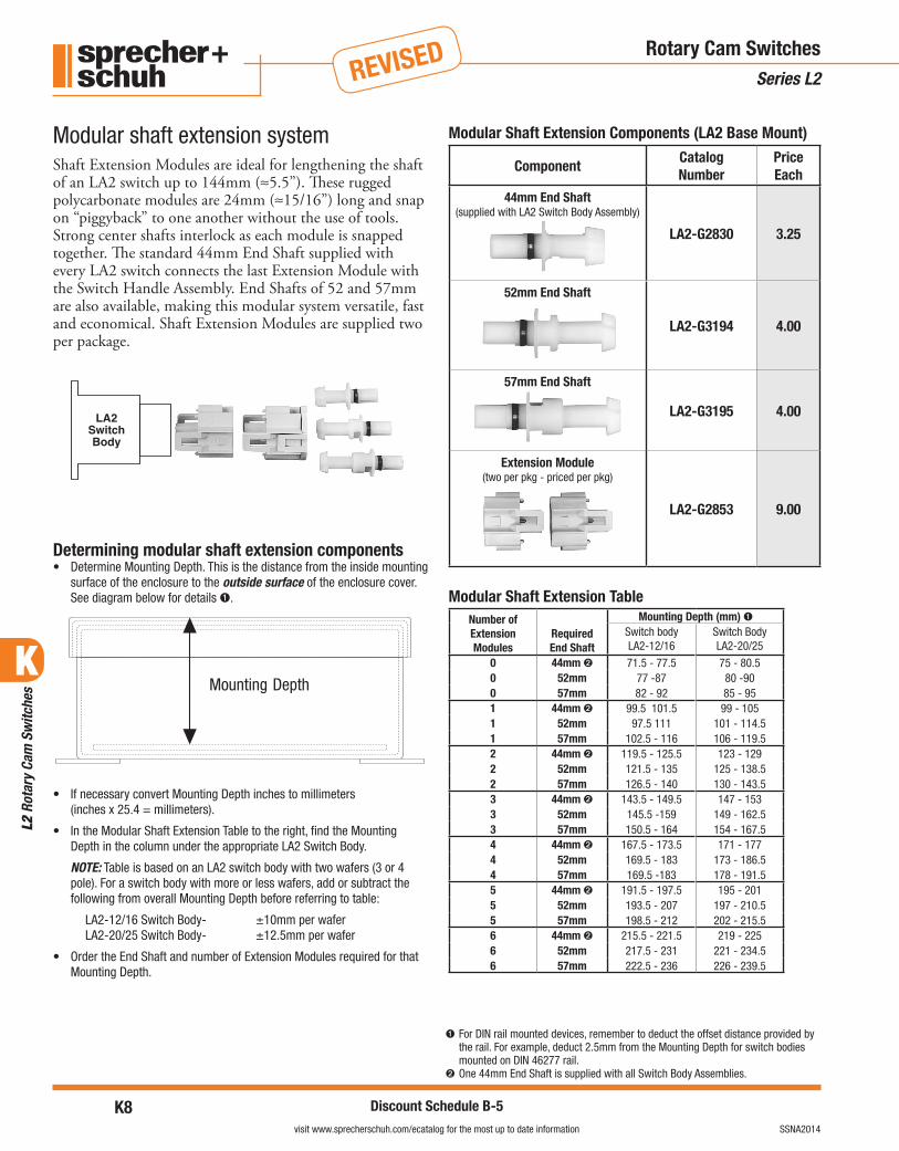
Modular Shaft Extension Components (LA2 Base Mount)
ComponentCatalog Number
Price Each
44mm End Shaft (supplied with LA2 Switch Body Assembly)
LA2-G2830 3.25
52mm End Shaft
LA2-G3194 4.00
57mm End Shaft
LA2-G3195 4.00
Extension Module(two per pkg - priced per pkg)
LA2-G2853 9.00
Modular Shaft Extension TableNumber of Extension Modules
Required End Shaft
Mounting Depth (mm) ➊Switch body LA2-12/16
Switch Body LA2-20/25
0 44mm ➋ 71.5 - 77.5 75 - 80.50 52mm 77 -87 80 -900 57mm 82 - 92 85 - 951 44mm ➋ 99.5 101.5 99 - 1051 52mm 97.5 111 101 - 114.51 57mm 102.5 - 116 106 - 119.52 44mm ➋ 119.5 - 125.5 123 - 1292 52mm 121.5 - 135 125 - 138.52 57mm 126.5 - 140 130 - 143.53 44mm ➋ 143.5 - 149.5 147 - 1533 52mm 145.5 -159 149 - 162.53 57mm 150.5 - 164 154 - 167.54 44mm ➋ 167.5 - 173.5 171 - 1774 52mm 169.5 - 183 173 - 186.54 57mm 169.5 -183 178 - 191.55 44mm ➋ 191.5 - 197.5 195 - 2015 52mm 193.5 - 207 197 - 210.55 57mm 198.5 - 212 202 - 215.56 44mm ➋ 215.5 - 221.5 219 - 2256 52mm 217.5 - 231 221 - 234.56 57mm 222.5 - 236 226 - 239.5
Modular shaft extension systemShaft Extension Modules are ideal for lengthening the shaft of an LA2 switch up to 144mm (≈5.5”). These rugged polycarbonate modules are 24mm (≈15/16”) long and snap on “piggyback” to one another without the use of tools. Strong center shafts interlock as each module is snapped together. The standard 44mm End Shaft supplied with every LA2 switch connects the last Extension Module with the Switch Handle Assembly. End Shafts of 52 and 57mm are also available, making this modular system versatile, fast and economical. Shaft Extension Modules are supplied two per package.
Determining modular shaft extension components• Determine Mounting Depth. This is the distance from the inside mounting
surface of the enclosure to the outside surface of the enclosure cover. See diagram below for details ➊.
• If necessary convert Mounting Depth inches to millimeters (inches x 25.4 = millimeters).
• In the Modular Shaft Extension Table to the right, find the Mounting Depth in the column under the appropriate LA2 Switch Body.
NOTE: Table is based on an LA2 switch body with two wafers (3 or 4 pole). For a switch body with more or less wafers, add or subtract the following from overall Mounting Depth before referring to table:
LA2-12/16 Switch Body- ±10mm per waferLA2-20/25 Switch Body- ±12.5mm per wafer
• Order the End Shaft and number of Extension Modules required for that Mounting Depth.
➊ For DIN rail mounted devices, remember to deduct the offset distance provided by the rail. For example, deduct 2.5mm from the Mounting Depth for switch bodies mounted on DIN 46277 rail.
➋ One 44mm End Shaft is supplied with all Switch Body Assemblies.
Rotary Cam SwitchesSeries L2

K
L2
Rota
ry C
am S
witc
hes
K9visit www.sprecherschuh.com/ecatalog for the most up to date informationSSNA2014
Discount Schedule B-5
REVISED
Metal Shaft Extension Components (LA2 Base Mount)
ComponentCatalog Number
Price Each
Short Metal Shaft
Length: 10 . . . 235mm (4-21/64…9-1/4 in.)
LA2-G3393 37
Long Metal Shaft
Length: 230 . . . 350mm (9-3/64…13-51/64 in.)
LA2-G3394 47
Insert - For modifying metal shaft to switch position LA2-G3398 4
Insert - For modifying metal shaft to switch any position (not lockable)
LA2-G3399 4
Metal Shaft Extension TableMetal Shaft Extension
Mounting Depth (mm) ➊Switch body LA2-12/16 Switch Body LA2-20/25
LA2-G3393 178 ➋ - 309 181.5 ➋ - 312.5
LA2-G3394 298 - 424 301.5 - 427.5
Rotary Cam SwitchesSeries L2
Metal shaft extension systemAdjustable metal shaft extensions snap on securely to LA2 switches via the same quick-connect design as shaft exten-sion modules. Metal shafts are equipped with a door in-terlock and a padlock hasp for locking out the switch after the enclosure is opened (for outside lockout, select a Switch Handle Assembly with lockout capability).
Two standard lengths of these unique adjustable shafts are available. Metal shaft extensions mate with any of the standard Switch Handle Assemblies. All necessary hardware is supplied with the shaft.
Determining metal shaft extension• Determine Mounting Depth. This is the distance from the inside mounting
surface of the enclosure to the outside surface of the enclosure cover. See diagram below for details ➊.
• If necessary convert Mounting Depth inches to millimeters (inches x 25.4 = millimeters).
• In the Metal Shaft Extension Table to the right, find the Mounting Depth in the column under the appropriate LA2 Switch Body.
NOTE: Table is based on an LA2 switch body with two wafers (3 or 4 pole). For a switch body with more or less wafers, add or subtract the following from overall Mounting Depth before referring to table:
LA2-12/16 Switch Body- ±10mm per waferLA2-20/25 Switch Body- ±12.5mm per wafer
• Order the Metal Shaft Extension required for that Mounting Depth.
➊ For DIN rail mounted devices, remember to deduct the offset distance provided by the rail. For example, deduct 2.5mm from the Mounting Depth for switch bodies mounted on DIN 46277 rail.
➋ This dimension can be reduced by another 55mm by cutting the plastic sleeve and further cutting the metal shaft.

K
L2
Rota
ry C
am S
witc
hes
K10visit www.sprecherschuh.com/ecatalog for the most up to date information SSNA2014
Discount Schedule B-5
REVISED
Accessory Description Catalog No.Price Each
(Plastic Reducer included)
End Shaft for LE switch• Replacement 44mm
shaft supplied standard with all switches
• Sold only in packages of 5. Order 5 pieces to receive 1 pkg of 5.
L2-G3380 5.00
Terminal cover3 or 4 pole
LE2-12/16LE2-20/25LA2-12/16LA2-20/25
LE2-12-C4LE2-20-C4LA2-12-C4LA2-20-C4
6.006.006.007.00
Standard knobBlack 37.5mmBlack 48mmRed 37.5mmRed 48mm
L2-G3154NL2-G3155NL2-G3154RL2-G3155R
3.503.503.503.50
Padlockable knobBlackRed
L2-G2864NL2-G2864R
7.157.15
Type “P” knobBlackRed
L2-G2888NL2-G2888R
5.005.00
Self contained knob - allows mounting LE2 switches without Switch Handle Assembly
IP40 protectionIP65 protection
L2-G2851NL2-G2854N
6.509.00
Legend Plate - Blank for engraving
SilverFor 48 x 48 (or 62)For 64 x 64 (or 78)
LL2-A-4-000LL2-A-6-000
2.552.95
YellowFor 48 x 48 (or 62)For 64 x 64 (or 78)
LL2-I-4-000LL2-I-6-000
2.552.95
Accessory Description Catalog No.Price Each
Switch handle assembly for 45mm standard cutout
O-IOFF-ONBlank
LFS2-P-4-175LFS2-P-4-175ILFS2-P-4-000
11.5011.5011.50
ABS Enclosure – For High Impact Applications (IP66, UL 94 Flame Resistance - HB)
With pre-drilled holes for 64 x 64 operator or larger
95x150x86mm95x150x111mm
LA2-G3572LA2-G3573
50.5050.50
Without holes95x150x86mm95x150x111mm
LA2-G3574LA2-G3575
44.0048.50
Noryl Enclosure – For Corrosion Prone Applications (IP66, UL 94 Flame Resistance - V0)
With pre-drilled holes for 64 x 64 operator or larger
95x150x86mm 95x150x111mm
LA2-G3576LA2-G3577
69.0083.00
Without holes95x150x86mm95x150x111mm
LA2-G3578LA2-G3579
67.7576.25
Enclosure Selection GuideDetermine switch & number of poles; order enclosure and shaft required
Base Mount Switch Poles Use Enclosure... Shaft Required ➊
LA2-12 & 161
LA2-G357(2,4,6,8)
LA2-G3195Standard2
LA2-20 & 251 LA2-G3194
Standard2
LA2-12 & 163
LA2-G357(3,5,7,9)
LA2-G3195LA2-G3194Standard
45
LA2-20 & 253 LA2-G31944 Standard
AccessoriesSeries L2 Rotary Cam Switches
➊ Order shafts from page K9.
L2 Switch Accessories

K
L2
Rota
ry C
am S
witc
hes
K11visit www.sprecherschuh.com/ecatalog for the most up to date informationSSNA2014
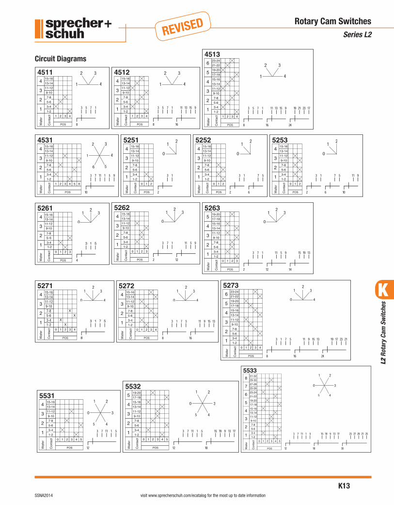
REVISED Rotary Cam SwitchesSeries L2
Circuit Diagrams

K
L2
Rota
ry C
am S
witc
hes
K12visit www.sprecherschuh.com/ecatalog for the most up to date information SSNA2014
REVISED Rotary Cam SwitchesSeries L2
Circuit Diagrams
8 168
K
L2
Rota
ry C
am S
witc
hes
K13visit www.sprecherschuh.com/ecatalog for the most up to date informationSSNA2014
REVISED Rotary Cam SwitchesSeries L2
Circuit Diagrams
X
15-1613-1411-129-107-85-63-41-2
XX
X

K
L2
Rota
ry C
am S
witc
hes
K13.1visit www.sprecherschuh.com/ecatalog for the most up to date informationSSNA2014
REVISED Rotary Cam SwitchesSeries L2
Circuit Diagrams
1U
2U
1W
2W
2V 1V
10 12

K
L2
Rota
ry C
am S
witc
hes
K14visit www.sprecherschuh.com/ecatalog for the most up to date information SSNA2014
REVISED
IP0…
No protection Protected againstvertically fallingdrops of water(condensation)
Protectedagainst drippingwater with en-closure up to 15°from vertical
Protectedagainst sprayedwater up to 60°from vertical
Protected againstsprayed waterfrom all directions(limited ingresspermitted)
Protected againstlow pressure wa-ter jets from alldirections (limitedingress permitted)
Protected againststrong jets of wa-ter from all direc-tions
Protected againstimmersion up toone meter
Protected againstlong periods ofimmersion underpressure
IP…0 IP…1 IP…2 IP…3 IP…4 IP…5 IP…6 IP…7 IP…8
IP00
IP10 IP11 IP12
IP20 IP21 IP22 IP23
IP30 IP31 IP32 IP33 IP34
IP40 IP41 IP42 IP43 IP44
IP50 IP53 IP54 IP55 IP56
IP60 IP65 IP66 IP67
No protection
Protected againstsolid objects up to50mm (accidentaltouch by hands)
Protected againstsolid objects up to12mm (fingers,knuckles)
Protected againstsolid objects up to2.5mm (tools, wires)
Protected againstsolid objects up to1mm (wires)
Protected againstdust (limited engresspermitted)
Totally protectedagainst dust
IP1…
IP2…
IP3…
IP4…
IP5…
IP6…
1 meter
IP RatingsDefinitionsThe first IP number (leftside of chart) isprotection against solidobjects. The second IPnumber (across top) isprotection againstliquids. The chart itselfshows degrees ofprotection according toIEC 529.
Technical InformationIP Ratings Definitions
IP Ratings Definitions
K
L2
Rota
ry C
am S
witc
hes
K15visit www.sprecherschuh.com/ecatalog for the most up to date informationSSNA2014
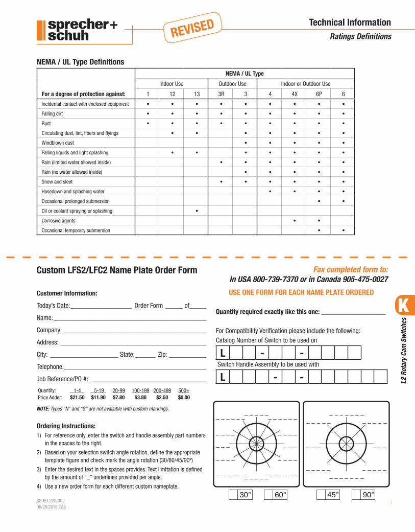
REVISED Technical InformationRatings Definitions
For a degree of protection against:
NEMA / UL Type
Indoor Use Outdoor Use Indoor or Outdoor Use
1 12 13 3R 3 4 4X 6P 6
Incidental contact with enclosed equipment • • • • • • • • •
Falling dirt • • • • • • • • •
Rust • • • • • • • • •
Circulating dust, lint, fibers and flyings • • • • • • •
Windblown dust • • • • •
Falling liquids and light splashing • • • • • • •
Rain (limited water allowed inside) • • • • • •
Rain (no water allowed inside) • • • • •
Snow and sleet • • • • • •
Hosedown and splashing water • • • •
Occasional prolonged submersion • •
Oil or coolant spraying or splashing •
Corrosive agents • •
Occasional temporary submersion • •
NEMA / UL Type Definitions
Customer Information:
Today’s Date: __________________ Order Form _____ of_____
Name: _____________________________________________
Company: __________________________________________
Address: ___________________________________________
City: ____________________ State: ______ Zip: ___________
Telephone: __________________________________________
Job Reference/PO #: __________________________________
Quantity: 1-4 5-19 20-99 100-199 200-499 500+Price Adder: $21.50 $11.90 $7.80 $3.80 $2.50 $0.00
NOTE: Types “N” and “G” are not available with custom markings.
Ordering Instructions:1) For reference only, enter the switch and handle assembly part numbers
in the spaces to the right.
2) Based on your selection switch angle rotation, define the appropriate template figure and check mark the angle rotation (30/60/45/90º)
3) Enter the desired text in the spaces provides. Text limitation is defined by the amount of “_” underlines provided per angle.
4) Use a new order form for each different custom nameplate.
SS-99-220-30206/26/2016 CAS
USE ONE FORM FOR EACH NAME PLATE ORDERED
Quantity required exactly like this one: ___________________
For Compatibility Verification please include the following:Catalog Number of Switch to be used on
L - - Switch Handle Assembly to be used with
L - -
Fax completed form to:In USA 800-739-7370 or in Canada 905-475-0027
Custom LFS2/LFC2 Name Plate Order Form

K
L2
Rota
ry C
am S
witc
hes
K16visit www.sprecherschuh.com/ecatalog for the most up to date information SSNA2014
REVISED Technical InformationSeries L2 Rotary Cam Switches
Technical InformationUL/CSA L2-12 L2-16 L2-20 L2-25General use
1-phase/2-phase, 3-phase/3 poles Rated current 600 V 12 16 20 25Heavy Pilot Duty code designation AC A600 A600 ~ ~Standard Duty code designation DC ~ ~ ~ ~
Alternating Current (IEC / EN 60947-3)
Rated Voltage Ue IEC-EN / UL-CSA (V) 690/600 690/600 690/600 690/600Rated Isolation Voltage Ui IEC / UL-CSA (V) 690/600 690/600 690/600 690/600Rated impulse voltage Uimp IEC (kV) 6 6 6 6
Test voltage Ui 1 min. (kV) 2.5 2.5 2.5 2.5
Rated frequency (Hz) 50/60 50/60 50/60 50/60
Thermal rated current Ith open (A) 16 20 25 30
Thermal rated current Ithe enclosed (A) 12 16 20 25Wasted power by 1 pole at thermal rated current Ithe (W) 0.3 0.5 0.6 0.9
Rated Operating Current Ie
AC-1/ AC21A
Switching resistive loads with slight overload
IEC947 690V (A) 12 16 20 25
AC-1 Non-inductive or slightly inductive loads inductive loads SEV 690V (A) 12 16 20 25
AC-22A Switching mixed resistive and inductive loads at slight overload
IEC947
220-500V (A) 12 16 20 25
600V (A) 12 16 20 25AC-15 Switching magnetic drives, motors,
valves and solenoidsIEC 220-240V (A) 5 6 7 8
380-415V (A) 3 4 5 6
500V (A) 2 2.5 3 4
Pilot Duty
Rated current
Non-inductive or slightly inductive loads
UL/CSA – Heavy VAC A600 A600 — —UL/CSA ➊ (A) 12 16 20 25
Short Circuit Current
Max. fuse rating of circuit (gL characteristic) (A) 35 35 60 80Rated conditional (kA) 5 5 5 5
Rated Operating Powers IEC/VDE/BS
AC-2 Slip ring motors, starting induction motors, reversing and plugging, wye-delta starting
240V (kW) 3 4 5.5 5.5
380V (kW) 5.5 7.5 9 133Ø 415V (kW) 5.5 7.5 9 133 pole 440V (kW) 5.5 7.5 9 13
500V (kW) 7.5 10 11 15
660V (kW) 7.5 10 11 15AC-3 Starting squirrel-cage motors,
interruption while running3Ø 220-240V (kW) 2.2 3 4.5 5.53 pole 380-440V (kW) 4 5.5 7.5 11
500V (kW) 5.5 7.5 10 13
660V (kW) 5.5 7.5 8 111Ø 110V (kW) 0.75 1.1 1.2 1.62 pole 220-240V (kW) 1.3 2.2 2.5 3.2
380-440V (kW) 2.2 3.7 4.5 5.5
➊ Suitable for switching off load (AC-20) above 660V, but only up to 660V for switches with screws at the rear (LE switches).

K
L2
Rota
ry C
am S
witc
hes
K17visit www.sprecherschuh.com/ecatalog for the most up to date informationSSNA2014
REVISED
Technical InformationL2-12 L2-16 L2-20 L2-25
Rated Operating Loads (cont.) IEC/VDE/BSAC-4 Starting squirrel-cage
motors, reversing, braking, plugging
3Ø 220-240V (kW) 0.75 1.5 3 43 pole 380-415V (kW) 1.5 2.2 3.7 5.5
440-550V (kW) 1.5 2.2 3.7 5.5660V (kW) — — — —
AC-23A Periodic switching of motors or other highly inductive loads.
3Ø 220-240V (kW) 2.2 3 4.5 5.53 pole 380-440V (kW) 4 5.5 7.5 11
500V (kW) 5.5 7.5 10 13660V (kW) 5.5 7.5 8 11
1Ø 110V (kW) 0.75 1.1 1.2 1.62 pole 220-240V (kW) 1.3 2.2 2.5 3.2
380-440V (kW) 2.2 3.7 4.5 5.5Rated Power UL/CSA (FLA) (FLA) (FLA) (FLA)
Normal motor load full voltage rating (similar to AC-3)
120V (HP) 1 (7.2) 1.5 (12.0) 2 (13.6) 3 (19.2)3Ø 240V (HP) 2 (6.8) 3 (9.6) 4 (12.4) 6 (18.0)3 pole 480V (HP) 5 (7.6) 7.5 (11.0) 8 (11.6) 12 (17.0)
600V (HP) 5 (6.1) 7.5 (9.0) 10 (11.0) 15 (17.0)1Ø 120V (HP) 0.5 (9.8) 0.75 (13.8) 1 (16) 1.5 (20.0)2 pole 240V (HP) 1 (8.0) 1.5 (10.0) 2 (12) 3 (17.0)
DC Switch Ratings Contacts in Series1 2 3 4 5 6 8
Rated Current IeRated Voltage [V] 24 48 72 96 120 144 192 [A] 12 16 20 22
DC-21A 48 96 144 192 240 288 384 [A] 10 12 16 18For resistive loads T ≤ 1ms Ue max = 600V
60 120 180 240 300 360 450 [A] 8 10 12 14110 220 330 440 550 660 – [A] 2 2.5 4 5220 440 660 – – – – [A] 0.5 0.6 0.7 0.8440 – – – – – – [A] 0.4 0.4 0.5 0.5
Rated Making/Breaking Capacity (=1.5 x Ie)1.05 x rated voltage [V] 25.2 50.4 75.6 100.8 126 151.2 201.6 [A] 18 24 30 33
50.4 100.8 151.2 201.6 252 302.4 403.2 [A] 15 21 24 27For resistive loads T ≤ 1msUe max = 600V
63 126 189 252 315 378 504 [A] 12 18 18 21
115.5 231 346.5 462 577.5 – – [A] 3 4.5 6 7.5231 462 – – – – – [A] 0.75 1.12 1.05 1.2462 – – – – – – [A] 0.52 0.78 0.47 0.75
Rated Current IeRated voltage [V] 24 48 72 96 120 144 192 [A] 8 10 12 14
30 60 90 120 150 180 240 [A] 4.5 5.5 7 8For inductive loads T = 50ms Ue max = 600V
48 96 144 192 240 288 384 [A] 1.5 2 2.5 360 120 180 240 300 360 450 [A] 1 1.2 1.5 1.8110 220 330 440 550 660 – [A] 0.4 0.5 0.6 0.7
Rated Making/Breaking Capacity (=1.1 x Ie)1.1 x rated voltage [V] 26.4 52.8 79.2 105.6 132 158.4 184.8 [A] 8.8 11 13.2 1.54
33 66 99 132 165 198 231 [A] 4.95 6.05 7.7 8.8For inductive loads T = 50ms 52.8 105.6 158.4 211.2 264 316.8 369.6 [A] 1.65 2.2 2.75 3.3Ue max = 600V 66 132 198 264 330 396 462 [A] 1.1 1.32 1.65 1.98
121 242 363 484 605 – – [A] 4.95 6.05 7.7 8.8Rated Power Pe
Rated voltage [V] Contacts in Series24 1 [kW] 0.12 0.15 0.20 0.25
DC-23A, DC-3, DC-5For inductive loads T ≤ 1ms
24 2 [kW] 0.20 0.25 0.30 0.3748 2 [kW] 0.25 0.30 0.37 0.5048 3 [kW] 0.30 0.37 0.50 0.7560 2 [kW] 0.25 0.30 0.37 0.5060 4 [kW] 0.37 0.50 0.75 1.00
110 4 [kW] 0.50 0.75 1.00 1.20110 6 [kW] 1.00 1.20 1.40 1.60220 4 [kW] 0.37 0.50 0.75 1.00220 6 [kW] 1.00 1.20 1.40 1.50
Technical InformationSeries L2 Rotary Cam Switches

K
L2
Rota
ry C
am S
witc
hes
K18visit www.sprecherschuh.com/ecatalog for the most up to date information SSNA2014
REVISED
Technical InformationL2-12 L2-16 L2-20 L2-25
Rated Making/Breaking Capacity(=4 x Ie)
1.05 x rated voltage [V] Contacts in Series25.2 1 [kW] 20.0 25.0 33.3 41.625.2 2 [kW] 33.3 41.6 50.0 61.6
DC-23A, DC-3, DC-5For inductive loads T ≤ 7.5ms
50.4 2 [kW] 21.0 25.0 30.8 41.650.4 3 [kW] 25.0 30.8 42.0 62.4
63 2 [kW] 16.6 20.0 24.6 33.263 4 [kW] 24.6 33.3 50.0 66.4
115.5 4 [kW] 18.1 27.2 36.4 44.0115.5 6 [kW] 36.4 43.6 51.0 58.2
231 4 [kW] 6.7 9.1 13.6 18.2231 6 [kW] 18.1 21.8 25.2 27.2
Maximum Wire GaugesRigid Wire AWG (2)18…12 (2)18…12 (2)16…10 (2)16…10
[mm2] (2)1…2.5 (2)1…2.5 (2)1.5…6 (2)1.5…6Fine Strands AWG (2)18…12 (2)18…12 (2)16…10 (2)16…10
[mm2] (2)1…2.5 (2)1…2.5 (2)1.5…4 (2)1.5…4Max. Torque Ratings [lb-in] 9 9 10.6 10.6
[Nm] 1 1 1.2 1.2Protection Class
Switch Handle AssemblyLFS2-G(N)-6… UL Type 12 Type 12 Type 12 Type 12All others IEC 529 IP66 IP66 IP66 IP66Switch Body IEC 529 IP20 IP20 IP20 IP20
Mechanical Life Millions of operations 1 1 1 1Rated Breaking Capacity 220V (A) 72 96 128 176
Power factor 0.65 0.65 0.65 0.35380V (A) 72 96 128 176Power factor 0.65 0.65 0.65 0.35660V (A) 53 72 86 112Power factor 0.65 0.65 0.65 0.65
Ambient Temperature (Fº) (Fº) (Fº) (Fº)Operation Min…Max (C°) -25…+60
(-13…+140)-25…+60
(-13…+140)-25…+60
(-13…+140)-25…+60
(-13…+140)Storage only Min…Max (C°) -40…+80
(-40…+176)-40…+80
(-40…+176)-40…+80
(-40…+176)-40…+80
(-40…+176)Maximum Altitude (without derating) (m) ≤2000 ≤2000 ≤2000 ≤2000
(ft.) ≤6561 ≤6561 ≤6561 ≤6561Maximum MechanicalOperations (without derating) (cycle/hr.) 1200 1200 1200 1200Maximum Electrical Operation (without derating) (cycle/hr.) 120 120 120 120
Technical InformationSeries L2 Rotary Cam Switches
K
L2
Rota
ry C
am S
witc
hes
K19visit www.sprecherschuh.com/ecatalog for the most up to date informationSSNA2014
REVISED
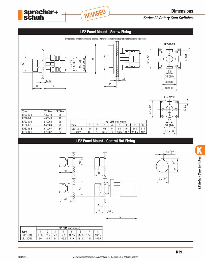
LE2-12/16
LE2-20/25
LE2 Panel Mount - Screw Fixing
LE2 Panel Mount - Central Nut Fixing
DimensionsSeries L2 Rotary Cam Switches
Type “Q” Dim “P” DimLFS2-A-4 48 X 48 28LFS2-I-4 48 X 48 28LFS2-A-6 64 X 64 28LFS2-I-6 64 X 64 28LFS2-N-6 67 X 67 34LFS2-G-6 67 X 67 34
Type“L” DIM (# of wafers)
1 2 3 4 5 6 7 8LE2-12/16 44 54 64 74 84 94 104 114LE2-20/25 44.5 57 69.5 82 94.5 107 119.5 132
Type“L” DIM (# of wafers)
1 2 3 4 5 6 7 8LE2-12/16 67.5 77.5 87.5 97.5 107.5 117.5 127.5 137.5LE2-20/25 69 81.5 94 106.5 119 131.5 144 156.5
Dimensions are in millimeters (inches). Dimensions not intended for manufacturing purposes.

K
L2
Rota
ry C
am S
witc
hes
K20visit www.sprecherschuh.com/ecatalog for the most up to date information SSNA2014
REVISED
LA2 Base Mount
LA2 Base Mount with Modular Shaft Extensions
DimensionsSeries L2 Rotary Cam Switches
“R”
“L” Dim (# of wafers)
LA2-12/16 LA2-20/25
1 2 3 4 1 2 3 4
1 Module 82 92 102 112 83 95.5 108 120.5
2 Modules 106 116 126 136 107 119.5 132 144.5
3 Modules 130 140 150 160 131 143.5 156 168.5
4 Modules 154 164 174 184 155 167.5 180 192.5
5 Modules 178 188 198 208 179 191.5 204 216.5
6 Modules 202 212 222 232 203 215.5 228 240.5
* Add 2.5mm for DIN rail 46277.
• With more than 4 modules attach the first one to the switch with the screws supplied with the LA2-G2853.
Type “Q” Dim “P” Dim “B” DimLFS2-A-4 48 X 48 28 36LFS2-I-4 48 X 48 28 36LFS2-A-6 64 X 64 28 48LFS2-I-6 64 X 64 28 48LFS2-N-6 67 X 67 34 48LFS2-G-6 67 X 67 34 48
Type“L” DIM (# of wafers)
1 2 3 4LA2-12/16 58 68 78 88LA2-20/25 59 71.5 84 96.5
* Add 2.5mm for DIN rail 46277.
Type “Q” Dim “B” DimLFS2-A-4 48 X 48 36LFS2-I-4 48 X 48 36LFS2-A-6 64 X 64 48LFS2-I-6 64 X 64 48LFS2-N-6 67 X 67 48LFS2-G-6 67 X 67 48
Shaft “F” “Y” DimLA2-G2830 2.5-9.5LA2-G3194 9 - 18LA2-G3195 14 - 23
Dimensions are in millimeters (inches). Dimensions not intended for manufacturing purposes.

K
L2
Rota
ry C
am S
witc
hes
K21visit www.sprecherschuh.com/ecatalog for the most up to date informationSSNA2014
REVISED
LA2 Base Mount with Metal Shaft Extension
LA2 Base Mount with LFS2-P-4
DimensionsSeries L2 Rotary Cam Switches
Type“L” DIM (# of wafers)
1 2 3 4LA2-12/16 54 64 74 84LA2-20/25 55 67.5 80 92.5
* Add 2.5mm for DIN rail 46277.
Type “A” DimLA2-G3393 110 - 235LA2-G3394 230 - 350
Type“L” DIM (# of wafers)
1 2 3 4LA2-12/16 35 45 55 65LA2-20/25 35.5 48 60.5 73
* Add 2.5mm for DIN rail 46277.
Dimensions are in millimeters (inches). Dimensions not intended for manufacturing purposes.

K
R-L
ine
Rota
ry C
am S
witc
hes
K22visit www.sprecherschuh.com/ecatalog for the most up to date information SSNA2014
Upda
ted
02-0
9-15
R-Line Series 40 Amp Rotary CamSwitches
Rugged and dependable 40 amp switches for industrial applications
Sprecher + Schuh’s rugged R-Line rota-ry cam switches are available for most control and load applications up to 40 amps. A well thought out ordering system provides many standard and nonstandard configurations, that are often available “off the shelf.” Many popular switching configurations are offered from stock.
…For many applicationsR-Line control and load switches com-ply with the most important interna-tional standards for use as:
• Changeover Switches - for switching between alternate electrical supplies.
• ON/OFF switches - to connect and disconnect any electrical supply.
• Multi-position load switches - for the step control of loads such as heat-ers and furnaces.
• Motor load disconnect switches - for safely isolating circuits during repair and maintenance.
• Reversing switches - to change the direction or rotation of a motor.
• Wye-Delta switches - To manually control reduced voltage starting of a motor.
Rugged qualityThe R-Line’s sturdy design incorpo-rates a positive switching action with a clearly defined switch position. The contact assemblies themselves are brass plated and have generous copper con-tent to help dissipate heat.
Solid connectionsThe terminal connections are a captive screw design with self-lifting saddle clamps. The saddle clamp design guarantees reliable connections on the R-40. The switch connection terminals are finger safe with IP20 protection.
Choose from various switch handle assembliesSwitch handle assemblies for our Changeover and ON-OFF switches are available with either traditional screw fixing or the new central nut fixing system. All switch handles offer Type 12 IP66 protection. A UL 4X handle is also available ordered separately.
REVISED February 2015This section has been revised since publication. Catalog Numbers not shown have been obsoleted.

K
R-Li
ne R
otar
y Ca
m S
witc
hes
K23visit www.sprecherschuh.com/ecatalog for the most up to date informationSSNA2014
Discount Schedule K1
Upda
ted
03-1
8-15
Switch Body Description
Catalog Number ➋ Price
Switch Handle Type 12/ IP66 ➌ Function Switch
Angle
Poles/Switch Wafers
Step
Screw Fixing
45° 1 / 2 RE-40-5261-A 175
Reversing
Screw Fixing
45° 3 / 3 RE-40-7303-A 187
Wye-Delta
Screw Fixing
45°/90° 3 / 4 RE-40-7323-A 238
Single Winding (Two Speed)
Screw Fixing
45° 3 / 4 RE-40-7293-A 238
Switch Description
Catalog Number ➋ Price
Switch Handle Type 12/ IP66 ➌ Function Switch
Angle
Poles/Switch Wafers
ON - OFF
Screw Fixing
90° 1 / 1 RE-40-1751-A 10190° 2 / 1 RE-40-1752-A 11890° 3 / 2 RE-40-1753-A 13590° 4 / 2 RE-40-1754-A 14990° 6 / 3 RE-40-1756-A 192
Screw Fixing
90° 3 / 2 RE-40-1753-N 16090° 4 / 2 RE-40-1754-N 18790° 6 / 3 RE-40-1756-N 232
Central Nut Fixing
90° 2 / 1 RC-40-1752-B 14990° 3 / 2 RC-40-1753-B 16690° 4 / 2 RC-40-1754-B 18190° 6 / 3 RC-40-1756-B 223
Central Nut Fixing
Key removal
90° 2 / 1 RC-40-1752-DD 19490° 3 / 2 RC-40-1753-DD 21190° 4 / 2 RC-40-1754-DD 22590° 6 / 3 RC-40-1756-DD 268
Changeover
Screw Fixing
45° 1 / 1 RE-40-3251-A 11845° 2 / 2 RE-40-3252-A 15645° 3 / 3 RE-40-3253-A 19345° 4 / 4 RE-40-3254-A 250
Screw Fixing
45° 3 / 3 RC-40-3253-B 22545° 4 / 4 RC-40-3254-B 281
Central Nut Fixing
Key removal
45° 3 / 3 RC-40-3253-DC 26945° 4 / 4 RC-40-3254-DC 326
➊ Rated current can be lower depending on application. Check R-Line Technical Section before selecting switch size.➋ See K28 for Circuit Diagrams.➌ See page K6 for description of switch handles.
Rotary Cam SwitchesSeries R-Line
R-Line Front Mounted 40 Amp Rotary Switches with Handle ➊
See Ordering Instructions on next page. ➠
REVISED

K
R-L
ine
Rota
ry C
am S
witc
hes
K24visit www.sprecherschuh.com/ecatalog for the most up to date information SSNA2014
Discount Schedule K1
Upda
ted
07-2
9-15
Switch Body Description
Catalog Number ➋ Price
Switch Handle Type 12/ IP66 ➌
Function Switch Angle
Poles/Switch Wafers
ON-OFF
Screw Fixing
90° 3 / 2 RA-40-1753-A 17990° 4 / 2 RA-40-1754-A 19490° 6 / 3 RA-40-1756-A 236
Screw Fixing
90° 3 / 2 RA-40-1753-N 18790° 4 / 2 RA-40-1754-N 20090° 6 / 3 RA-40-1756-N 240
Rotary Cam SwitchesSeries R-Line
R-Line Base Mounted 40 Amp Rotary Switches with Handle ➊
A UL Type 4X switch handle is available for RA-40 switches. First select switch from this page, then turn to Accessories Section (page K40) and order Type R switch handle separately.
➊ Rated current can be lower depending on application. Check R-Line Technical Section before selecting switch size.
➋ See K28 for Circuit Diagrams.➌ See page K6 for description of switch handles.➍ Not available on RA-40 Base Mounted switches.
RE-40 – 1753 – ASwitch Configuration Circuit Diagram # ➋ Handle Code ➌ for use with
RE -
RA -
RC -
Front (Panel) Mounted 40 amp switch
Base Mounted 40 amp switch
Front (Panel mounted Central Nut fixing
1751-1756 ON-OFF3251-3504 Changeover5261 Step7293 Single Winding7303 Reversing7323 Wye-Delta
A -B -N -
DC -DD -
Type AType B ➍Type NType DC ➍Type DD ➍
RE/RA switchRC switchRE/RA switchRC switchRC switch
Catalog numbers include a complete switch and handle kit.
Ordering Instructions
REVISED

K
R-Li
ne R
otar
y Ca
m S
witc
hes
K25visit www.sprecherschuh.com/ecatalog for the most up to date informationSSNA2014
Discount Schedule B-5
Upda
ted
04-1
7-17
Accessory Description Catalog No. Price
(Reducer not included)
Shaft for RE switch(One supplied with each LE switch)
L2-G3380 5.00
Standard knob37.5 mm Black Red48 mm Black Red
L2-G3154NL2-G3154R
L2-G3155NL2-G3155R
3.50
3.50
Padlockable knobBlack L2-G2864N 7.15Red L2-G2864R
Self-contained knoballows mounting RE-40 switches without Switch Handle Assembly
IP40 protection L2-G2851N 6.50
IP65 protection L2-G2854N 9.00
LFS2-N
“ON-OFF” SwitchHandle AssemblyType 12, IP66, accepts 3 padlocks
Yellow and Red LFS2-N-6-175 21.00Gray and black LFS2-G-6-175
Type R “ON-OFF” SwitchHandle Assembly ➊➋Screw fixing. Type 3R, 3, 12, 4, 4X, and IP66
See page
L9
Black and Black LA7-SBYellow and Red LA7-SY
Type R “ON-OFF” SwitchHandle Assembly ➊➋➌ Screw fixing. Type 3R, 3, 12, 4, 4X, and IP66
See page L31
Black and Black L11-PBYellow and Red L11-PY
R-Line Switch Accessories
AccessoriesSeries R-Line
➊ Switch handle can be field modified to be defeatable or non-defeatable.➋ Handles LA7-S_ and L11-P_ require R-type Switch Handle Shaft Extension. See page L13.➌ Switch handle can be field modified to be defeatable or non-defeatable.
Accessory Description Catalog No. Price
Front frame(blank nameplate) L2-G3196 11.50
Legend plate -blank for engravingSilver LL2-A-6-000 2.95Yellow LL2-I-6-000
Legend plate -O - I, 90°
Yellow LL2-I-6-175 2.95
Terminal cover -3 or 4 pole
For RA-40 RA-40-C4 15.50For RE-40 RE-40-C4 11.35
Dust Cover(not IP rated)FOR RE-40
1 or 2 switch wafers RE-G3180 32.753 or 4 switch wafers RE-G3181 37.005 or 6 switch wafers RE-G3182 43.00

K
R-L
ine
Rota
ry C
am S
witc
hes
K26visit www.sprecherschuh.com/ecatalog for the most up to date information SSNA2014
Discount Schedule B-5
Upda
ted
02-0
9-15
Component Catalog Number Price
44mm End Shaft (suppliedwith RA-40 Switch Body Assembly)
LA2-G2830 3.25
52mm End Shaft
LA2-G3194 4.00
57mm End Shaft
LA2-G3195 4.00
Extension Module(two per pkg - priced per pkg)
LA2-G2853 9.00
➊ For Type R (4X) switch handle shaft extensions, see “Type R Switch Handle Extension” table on opposite page.
➋ One 44mm End Shaft is supplied with all Switch Body Assemblies.
Rotary Cam SwitchesSeries R-Line
Modular Shaft Extension Components (RA40 Base Mount)
RA-40SwitchBody
Modular Shaft Extension system ➊Shaft Extension Modules are ideal for lengthening the shaft of an RA-40 switch up to 144mm (≈5.5”). These rugged polycarbonate modules are 24mm (≈15/16”) long and snap on “piggyback” to one another without the use of tools. Strong center shafts interlock as each module is snapped together. The standard 44mm end shaft supplied with every RA-40 switch connects the last Extension Module to the Switch Handle Assembly. End shafts of 52 and 57mm are also available, making this modular system versatile, fast and economical. Shaft Extension Modules are supplied two per package.
Determining modular shaft extension components• Determine mounting depth. This is the distance from the inside mounting
surface of the enclosure to the outside surface of the enclosure cover. See diagram below for details.
• If necessary, convert mounting depth inches to millimeters (inches x 25.4 = millimeters).
• In the Modular Shaft Extension Table to the right, find the correct range for your enclosure in the Mounting Depth column.
NOTE: Table is based on an RA-40 switch body with two wafers (3 or 4 pole). For a switch body with more or less wafers, add or subtract the following from overall Mounting Depth before referring to table:
RA-40 Switch Body - ±17.5mm per wafer
• Order the End Shaft and number of Extension Modules required for that mounting depth.
Number of Extension Modules
Required End Shaft
Mounting Depth (mm)
Switch BodyRA-40
0 44mm ➋ 98.5 - 104.50 52mm 100.5 - 1140 57mm 109 - 1191 44mm ➋ 122.5 - 128.51 52mm 124.5 - 1381 57mm 133 - 1432 44mm ➋ 146.5 - 152.52 52mm 148.5 - 1622 57mm 157 - 1673 44mm ➋ 170.5 - 176.53 52mm 172.5 - 1863 57mm 181 - 1914 44mm ➋ 194.5 - 200.54 52mm 196.5 - 2104 57mm 205 - 215
Modular Shaft Extension Table

K
R-Li
ne R
otar
y Ca
m S
witc
hes
K27visit www.sprecherschuh.com/ecatalog for the most up to date informationSSNA2014
Discount Schedule B-5
Upda
ted
02-0
9-15
Metal shaft extension system ➊Adjustable metal shaft extensions snap on securely to RA-40 switches via the same quick-connect design as shaft extension modules. Metal shafts are equipped with a door interlock and a padlock hasp for locking out the switch after the enclosure is opened (for outside lockout, select a Switch Handle with lockout capability).
Two standard lengths of these unique adjustable shafts are available. Metal shaft extensions mate with any of the standard Switch Handles. All necessary hardware is sup-plied with the shaft.
Determining metal shaft extension• Determine Mounting Depth. This is the distance from the inside
mounting surface of the enclosure to the outside surface of the enclosure cover. See diagram below for details.
• If necessary convert Mounting Depth inches to millimeters (inches x 25.4 = millimeters).
• In the appropriate table to the right, find the correct range for your enclosure in the Mounting Depth column.
NOTE: Tables are based on an RA-40 switch body with two wafers (3 or 4 pole). For a switch body with more or less wafers, add or subtract the following from overall Mounting Depth before referring to table:
RA-40 Switch Body- ±17.5mm per wafer
• Order the Metal Shaft Extension required for that Mounting Depth and switch handle.
➊ Not for Type R (UL 4X) switch handles. Use Type R Switch Handle Extension table on this page.
➋ This dimension can be reduced by another 55mm by cutting the plastic sleeve and further cutting the metal shaft.
➌ Shaft included in package is designed for LA7-S_ and L11-P_ only. Not designed for use with previous L10-H_ handles.
Rotary Cam SwitchesSeries R-Line
RA-40SwitchBody
Type R Switch Handle Shaft Extensions ➌Only select shaft extension from this table if ordering the Type R (UL Type 4X) Switch Handle from the Accessories Section (page K25). Select shaft after figuring overall Mounting Depth.
Type R Switch Handle Shaft Extension (typical)
Mounting Depth (mm)
Catalog Number PriceSwitch Body RA-40
119 - 143 LA7-S-67
See page L13
124 - 148 LA7-S-72131 - 155 LA7-S-79139 - 163 LA7-S-87142 - 166 LA7-S-90149 - 173 LA7-S-97156 - 180 LA7-S-104167 - 191 LA7-S-115
Adjustable R-type Switch Handle Shaft Extension (LA7-S1-P shown)
Maximum length of 368 mm (14.5")
119 - 191 LA7-S1-P See page L13
Includes all parts except L11-S1 shaft, order separately
LA7-NS-P
Metal Shaft Extension Components (RA40 Base Mount)
ComponentCatalog Number
Price
Short Metal Shaft
Length: 10 . . . 235mm (4-21/64…9-1/4 in.)
LA2-G3393 37
Long Metal Shaft
Length: 230 . . . 350mm (9-3/64…13-51/64 in.)
LA2-G3394 47
Metal Shaft Extension TableMetal Shaft
Extension
Mounting Depth (mm)Switch Body
RA-40LA2-G3393 205 ➋ - 336
LA2-G3394 325 - 451

K
R-L
ine
Rota
ry C
am S
witc
hes
K28visit www.sprecherschuh.com/ecatalog for the most up to date information SSNA2014
Upda
ted
02-0
9-15
Circuit Diagrams
8
1U
2U
1W
2W
2V 1V
Y
∆
0
168
Rotary Cam SwitchesSeries R-Line

K
R-Li
ne R
otar
y Ca
m S
witc
hes
K29visit www.sprecherschuh.com/ecatalog for the most up to date informationSSNA2014
Upda
ted
02-0
9-15
Technical InformationSeries R-Line Rotary Cam Switches
➊ Values approved by IMQ
* approved resp. testing successful
Approvals*
Technical InformationR-40
Rated Operating Voltage UL/CSA [V] 600IEC/VDE/BS [V] 690
Rated Isolation VoltageImpulse [V] 8Continuous 690
Rated Thermal Current Ith UL/CSA [A] 40IEC/VDE/BS [A] 45
Rated Thermal Current Ithe IEC/VDE/BS [A] 45
Rated Operating Current Ie
AC-1/ AC21A
Switching resistive loads with slight overload
IEC947 690V [A] 40
AC-22A Switching mixed resistive and inductive loads at slight overload
IEC947
220-500V600V [A] 40
Short Circuit Current
Rated conditional (note type & fuse size) [kA] 5Maximum fuse rating of circuit, non-enclosed [A] 40UL fuse type Class J
Rated Operating Powers Pe ➊
AC-3 Squirrel-cage motors: starting and stopping of running motors
3Ø 230V [kW] 7.53 pole 400V [kW] 18.5
690V [kW] 18.5AC-4 Starting squirrel-cage
motor starting, reversing, electric braking, inching
3Ø 230V [kW] 5.5
3 pole 400V [kW] 7.5
500V [kW] 11
AC-23A Periodic switching ofmotors or other highlyinductive loads.
3Ø 230V [kW] 113 pole 400V [kW] 11
690V [kW] 22Rated Power UL/CSA
Across the line AC motor starting DOL-rating
120V [HP] 53Ø 240V [HP] 103 pole 480V [HP] 25
600V [HP] 251Ø 120V [HP] 22 pole 240V [HP] 5
480V [HP] 10
600V [HP] 15General use 600VAC [A] 40
Rated Breaking Capacity 690V [A] 196Power factor 0.45
DC-20 SwitchingRated operating current I
e [A] 40DC-1 Switching
DC-21A SwitchingRated operating current Ie [A] 25
V max pole [V] 60DC-23 Switching 24VDC [kW] 0.3 (1)Rated power 48VDC [kW] 0.5 (2)(the numbers in brackets indicate the number
60VDC [kW] 1 (2)
of poles that must be connected in series) 110VDC [kW] 2 (3)220VDC [kW] 2.2 (5)
R-40
DC-13 Switching 24VDC [A] 16L/R = 40ms 48VDC [A] 8
60VDC [A] 4.8110VDC [A] 2220VDC [A] 0.6380VDC [A] 0.4500VDC [A] 0.3
Maximum Wire GaugesSingle/multi-core wire (1 wire) [mm2] 10/6
[AWG] 8/10
Single/multi-core wire (2 wires) 10/10 10/10[AWG] 8/10
Minimum Wire Gauges (1 wire)Single/multi-core wire [mm2] 4/2.5
[AWG] 12/14Terminals Screw
Terminal Type M4Protection Class
Switch Handle AssemblyLFS2-G(N)-6… UL / IEC 529 Type 12 / IP66LA7-SB/SY UL 4/4XLFS(C)2-…4(6, 8, 13)… UL / IEC 529 Type 12 / IP66
Switch Body IEC 529 IP20Mechanical Life [Millions of ops.] 1Maximum MechanicalOperations (without derating) [cycle/hr.] 1200Maximum Electrical Operation (without derating) [cycle/hr.] 120
Ambient TemperatureOperation Min…Max [C°] -25…+60Storage only Min…Max [C°] -40…+80
Maximum Altitude (without derating) [m] ≤2000[ft.] ≤6561

K
R-L
ine
Rota
ry C
am S
witc
hes
K30visit www.sprecherschuh.com/ecatalog for the most up to date information SSNA2014
Upda
ted
04-1
7-17
DimensionsSeries R-Line Rotary Cam Switches
RE-40 Panel MountingDimensions are in millimeters (inches). Dimensions not intended for manufacturing purposes.
Type G/N Type A
Drill Plan (operator)
Type D (RC-40) Type B (RC-40)
Type“L” Dim (# of wafers)
1 2 3 4RE-40 41 58.5 76 93.5
Screw Fixing (RE-40)
Type
“L” Dim (# of wafers)1 2 3 4 5 6 7 8
RC-40 86 103.5 121 138.5 156 173.5 191 208.5
Central Fixing (RC-40)
Drill Plan (operator)
67x6
7
34
1...4 mm 1...4 mm
64x6
4
28
61
L
36x36 or48x48
9.5
33
ø 3.2
ø 3.2
41
ø 30
28 24.5
L
1...6 mm
RA-40 Base Mounting
For LA7-SB/SY Handle Dimensions see page L24For L11-PB/PY Handle Dimensions see page L53
Type G/N Type A
Drill Plan (operator) Drill Plan (base)
Type
“L” Dim (# of wafers)
1 2 3 4
RA-40 42.5 60 77.5 95
67x6
7
34
64x6
4
X
Y
28
70
L
36x36 or48x48
17
ø 3.2
70
70
M4

K
R-Li
ne R
otar
y Ca
m S
witc
hes
K31visit www.sprecherschuh.com/ecatalog for the most up to date informationSSNA2014
Upda
ted
02-0
9-15
DimensionsSeries R-Line Rotary Cam Switches
RA-40 Base Mount with LA2-G339_ Metal Shaft Extension
Dimensions are in millimeters (inches). Dimensions not intended for manufacturing purposes.
* Add 2.5mm for DIN rail 46277.
Type “A” DimLA2-G3393 110 - 235
LA2-G3394 230 - 350
Type
“L” Dim (# of wafers)
1 2 3 4
RA-40 42.5 60 77.5 95

K
R-L
ine
Rota
ry C
am S
witc
hes
K32visit www.sprecherschuh.com/ecatalog for the most up to date information SSNA2014
Upda
ted
02-0
9-15
Rotary Cam Switches
Notes