Ross et al. Date of Patent
15
111111111111111111111111111111111111111111111111111111111111111111111111111 US007029561B2 (12) United States Patent (10) Patent No.: US 7,029,561 B2 Ross et al. (54) FLUIDIC TEMPERATURE GRADIENT FOCUSING (75) Inventors: David Ross, Silver Spring, MD (US); Lauric E. Locascio, North Potomac, MD (US) (73) Assignee: The United States of America as represented by the Secretary of Commerce, Washington, DC (US) ( *) Notice: Subject to any disclaimer, the tenn of this patent is extended or adjusted under 35 u.s.c. 154(b) by 483 days. (21) App!. No.: 10/197,331 (22) Filed: Jul. 18, 2002 (65) Prior Publication Data US 2003/0019752 Al Jan. 30, 2003 Related U.S. Application Data (60) Provisional application No. 60/323,404, filed on Sep. 19, 2001, provisional application No. 60/307,691, filed on Jul. 25, 2001. (51 ) Int. Cl. GOIN 271447 (2006.01) GOIN 271453 (2006.01) (52) U.S. Cl. ...................... 204/451; 204/601; 204/450; 204/600 (58) Field of Classification Search ........ 204/451-455, 204/601-605,450,600 See application file for complete search history. (56) References Cited U.S. PATENT DOCUMENTS 3,664,939 A 5/1972 Luner et al. 5,021,646 A * 6/1991 Weinberger et al. ... 250/227.11 5,759,370 A 6/1998 Pawliszyn (45) Date of Patent: Apr. 18, 2006 5,795,720 A * 8/1998 Henco et al. .................. 435/6 6,277,258 BI * 8/2001 Ivory et al. ................. 204/450 6,749,735 Bl * 6/2004 Le Febre .................... 204/601 OTHER PUBLICATIONS Grushka et al. (Effect of Temperature Gradients on the Efficiency of Capillary Zone Electrophoresis Separations, Ana!' Chem. 1989, 61, 241-246), Feb.* Hinckley ("Electrophoretic Thermal Theory: I Temperature Gradients and their Effects," Journal of Chromatography, 109 (1975 209-217), Jun.* Knox et al. (Temperature Effects in Capillary Electrophoresis. 1: Internal Capillary Temperature and Eftect upon Performance. Chromatographia vol. 38, No. 3 / 4 Feb. 1994).* Birmes et a!. ("Analysis of the conformational transitions of proteins by temperature-gradient gel electrophoresis," Electrophoresis 1990, 11, 795-801), month unknown.* (Continued) Primary Examiner-Alex Noguerola (74) Attorney, Agent, or Firm-Stites & Harbison PLLC; Ross F. Hunt, Jr. (57) ABSTRACT A method and device are provided for concentrating and separating ionic species in solution within a fluidic device having a fluid conduit such as a channel or capillary. The concentration is achieved by balancing the electrophoretic velocity of an analyte against the bulk flow of solution in the presence of a temperature gradient. Using an appropriate buffer, the temperature gradient can generate a correspond- ing gradient in the electrophoretic velocity so that the electrophoretic and bulk velocities sum to zero at a unique point and the analyte will be focused at that point. The method and device may be adapted for use with a variety of analytes including fluorescent dyes, amino acids, proteins, DNA and to concentrate a dilute analyte. 37 Claims, 6 Drawing Sheets x ---------UEP / / -------_/ / u x ................................... UT •... ... .... .,', .. "....................... . UB
Transcript of Ross et al. Date of Patent
111111111111111111111111111111111111111111111111111111111111111111111111111 US007029561B2
(12) United States Patent (10) Patent No US 7029561 B2 Ross et al
(54) FLUIDIC TEMPERATURE GRADIENT FOCUSING
(75) Inventors David Ross Silver Spring MD (US) Lauric E Locascio North Potomac MD (US)
(73) Assignee The United States of America as represented by the Secretary of Commerce Washington DC (US)
( ) Notice Subject to any disclaimer the tenn of this patent is extended or adjusted under 35 usc 154(b) by 483 days
(21) App No 10197331
(22) Filed Jul 18 2002
(65) Prior Publication Data
US 20030019752 Al Jan 30 2003
Related US Application Data
(60) Provisional application No 60323404 filed on Sep 19 2001 provisional application No 60307691 filed on Jul 25 2001
(51 ) Int Cl GOIN 271447 (200601) GOIN 271453 (200601)
(52) US Cl 204451 204601 204450 204600
(58) Field of Classification Search 204451-455 204601-605450600
See application file for complete search history
(56) References Cited
US PATENT DOCUMENTS
3664939 A 51972 Luner et al 5021646 A 61991 Weinberger et al 25022711 5759370 A 61998 Pawliszyn
(45) Date of Patent Apr 18 2006
5795720 A 81998 Henco et al 4356 6277258 BI 82001 Ivory et al 204450 6749735 Bl 62004 Le Febre 204601
OTHER PUBLICATIONS
Grushka et al (Effect of Temperature Gradients on the Efficiency of Capillary Zone Electrophoresis Separations Ana Chem 1989 61 241-246) Feb Hinckley (Electrophoretic Thermal Theory I Temperature Gradients and their Effects Journal of Chromatography 109 (1975 209-217) Jun Knox et al (Temperature Effects in Capillary Electrophoresis 1 Internal Capillary Temperature and Eftect upon Performance Chromatographia vol 38 No
3 4 Feb 1994) Birmes et a (Analysis of the conformational transitions of proteins by temperature-gradient gel electrophoresis Electrophoresis 1990 11 795-801) month unknown
(Continued)
Primary Examiner-Alex Noguerola (74) Attorney Agent or Firm-Stites amp Harbison PLLC Ross F Hunt Jr
(57) ABSTRACT
A method and device are provided for concentrating and separating ionic species in solution within a fluidic device having a fluid conduit such as a channel or capillary The concentration is achieved by balancing the electrophoretic velocity ofan analyte against the bulk flow of solution in the presence of a temperature gradient Using an appropriate buffer the temperature gradient can generate a correspondshying gradient in the electrophoretic velocity so that the electrophoretic and bulk velocities sum to zero at a unique point and the analyte will be focused at that point The method and device may be adapted for use with a variety of analytes including fluorescent dyes amino acids proteins DNA and to concentrate a dilute analyte
37 Claims 6 Drawing Sheets
x
- - - - - - - - - UEP
-------_
u x UT
bull
UB
US 7029561 B2 Page 2
OTHER PUBLICATIONS
[iu et al (Separation of Chlorophenols by Capillary Zone Electrophoresis The influence of pH of the Electrophoretic Buffer on Selectivity Short Communications 1 High Resol Chromatogr vol 21 May 1998) Grossman et al (Effect of Buffer pH and Peptide Composhysition on the Selectivity of Peptide Separations by Capillary Zone Electrophoresis Analytical Biochemistry 173 265shy270 (1988)) Sep Lochmiiller et al Open-Channel Isoelectric Focusing In Thermally Engendered pH Gradients Journal 0 Chromashytography 480 (1989) pp 293-399 Liang Zhu Hian Kee Lee Bingcheng Lin and Edward S Yeung Spatial temperature gradient capillary electrophoresis for DNA mutation detection
Electrophoresis 22 3683-3687 (2001) Roger M Wartell Seyed Hosseini Sandra Powell and Jian Zhu Detecting single base substitutions mismatches and bulges in DNA by temperature gradient gel electrophoresis and related methods Journal 0 Chromatography A 806 169-185 (1998) Chen-Wen Whang and Edward S Yeung Temperature Programming in Capillary Zone Electrophoresis Anal Chem 64 502-506 (1992) B Crane C Hogan L Lemlan and IW Hunter DNA mutation detection via fluorescence imaging in a spatial themlal gradient capillary electrophoresis system Review aScientific Instruments vol 72 114245-4251 (2001)
cited by examiner
us Patent Apr 182006 Sheet 1 of 6 US 7029561 B2
PRIOR ART
4 Electrodes
3 ~ =-I---------~ 5
~______V_----A---__
V __----)
Section 1
Section 2
Microchannel
Fig l(a)
4
x
Fig 1(b)
us Patent Apr 182006 Sheet 2 of 6 US 7029561 B2
PRIOR ART
-------- - - - - - - - - - UEP
u(z) 1------~----_3to --____z_ LIT
bullbullbullbullbullbullbullbullbullbullbullbullbullbullbullbullbullbullbullbullbullbullbullbullbullbullbullbullbullbullbullbullbullbull 1 bullbullbullbullbullbullbullbullbullbullbullbullbullbullbull Uf3
Fig 2
us Patent Apr 182006 Sheet 3 of 6 US 7029561 B2
1 12
hot cold ~ 14 Fig3(a) high
Ir-_-_-=-__~~________ voltage-L microchannel 10
1 ____
Fig 3(b) T(z) ~ ----- shyz
Fig 3 (c) f(7(zraquo -------- z
Un bullbullbullbullbullbullbullbull 11 bullbullbullbull _bullbullbull It
Fig 3 (d) u(z) I--______~-___--
z _ _-_ -
-----_ - shy
us Patent Apr 182006 Sheet 4 of 6 US 7029561 B2
29
V2
24 22 ~ 27
20
Fig4(a)
) x
Fig4(b)
f(T)
Fig 4 (c)
x
- - - - - - - - - UEP
-------_
U~--------~--------__7 --___X_ UT
Ua
Fig 4 Cd)
us Patent Apr 182006 Sheet 5 of 6 US 7029561 B2
5561
54
51
Fig 5
us Patent Apr 182006 Sheet 6 of 6 US 7029561 B2
70 80 ___ r ~ detector
--___--I
74
77
77
Fig 6
10
20
30
40
50
60
US 7029561 B2 1
FLUIDIC TEMPERATURE GRADIENT FOCUSING
CROSS-REFERENCE TO RELATED APPLICATIONS
This application claims benefit of the filing date of both copending Provisional Patent Application Nos 60307691 filed on Jul 25 2001 and 60323404 filed on Sep 19 2001
STATEMENT REGARDING FEDERALLY SPONSORED RESEARCH
This invention was made by employees of the United 15 States Government and may be manufactured and used by or for the Govenunent for governmental purposes without the payment of any royalties
FIELD OF THE INVENTION
The present invention relates to a method for electrokishynetic focusing of samples and in particular methods for electro-focusing samples in fluidic devices using electric field gradients 25
BACKGROUND OF THE INVENTION
Over the past decade a great deal of research has been focused on the development of teclmology related to microshytotal-analytical systems This technology is based on the concept of a series of microfluidic chatmels also known as microchatmels for the movement separation reaction and or detection of various chemicals or biological compounds such as amino acids proteins atld DNA
35One disadvantage with prior micro fluidic devices is that
there is frequently a mismatch between the extremely small quatltities of sample used for analysis atld the often much larger quatltities needed for loading the sample into the microfluidic device atld transporting the sample to the point of analysis For example a typical analysis sample may be around one nanoliter or less of a liquid containing sample that is injected into a separation chatmel and then separated electrokinetic ally as it moves down the chatmel to a detecshytion region However the channels used to transport the 45
sample to the injection point are typically also filled with the Satllple thus increasing the required amount of the sample by a factor of 100 or more In addition the sample is typically loaded onto the micro fluidic device into a reservoir from a pipette so that in all approximately 999 of the sample is discarded as waste
Electric field gradient focusing is one way of addressing the problem of requiring a large sample for atlalysis due to the inefficiencies of conventional devices which result in wasted sample Electric field gradient focusing can be used 55
to concentrate samples at a given point within a micro fluidic device before the analysis step Further the electric field gradient can be used to concentrate all of the sample at the begiuning of the separation chatmel so that very little of the sample would be wasted
Electric field gradient focusing is accomplished by the application of an electric field gradient within a microchanshynel In response to the electric field gradient there is a corresponding gradient in the electrophoretic velocity ofany ion within the microchatmel The total velocity of the ion is 65
the sum of its electrophoretic velocity atld the bulk fluid velocity If these two components of the velocity are in
2 opposite directions they can be balanced so that the molshyecule will have zero total velocity
When there is a gradient in the electrophoretic velocity the balance between bulk and electrokinetic velocities can occur at a single point within the microcha11l1el and therefore can result in focusing of ions at that point Typically the electric field gradient used in focusing is generated by the external manipulation of the electric field in the middle of the microcha11l1el through the use of conducting wires salt bridges porous membranes or other structures that will pass electric current but will restrict the flow of bulk fluid and analytes that are to be focused
Several recent developments with regard to focusing methods in microfluidics and in particular the use of electric field gradients have been made A description of related methods of focusing can be found in C F Ivory W S Koegler R L Greenlee and V Surdigio Abstracts of Papers of the Americatl Chemical Society 207 177-BTEC (1994) c F Ivory Separation Science and Teclmology 35 1777 (2000) Z Huang and C F Ivory Analytical Chemistry 71 1628 (1999) W S Koegler and C F Ivory Journal of Chromatography a 726 229 (1996) and P II Ofarrell Science 227 1586 (1985) all of which are hereby incorposhyrated by reference
To illustrate the basic principles disclosed in these pubshylications reference is made to FIG lea) which depicts a length of buffer-filled microcha11l1el of constant cross-secshytional area with an electrode denoted 4 in the middle and two further electrodes at each end denoted 3 and 5 so that the voltages Vj V3 at the ends and the voltage at the middle of the chatmel can be controlled A single species of negatively charged analyte is present in a buffer that is provided to the microcha11l1el The electrical comlection represented as electrode 4 can be accomplished with a simple metal wire as depicted in FIG lea) or through a more complicated structure consisting of additional fluid chatmels and porous membrane structures or salt bridges
The electric field in the section 1 ie the cha11l1el between electrodes 3 and 4 is Ej=(V2-Vj)(l2) and the electric field in section 2 ie between electrodes 4 and 5 is E2=(V3 shy
V2)(l2) where Vjl V2 and V3 are the voltages applied to the three electrodes 3 4 and 5 and I is the length of the microchatmel If E j differs trom E2 as shown in FIG l(b) the electrophoretic velocity of the analyte in the cha11l1el uEF will be different in section 1 than in section 2 If an overall bulk fluid velocity uBltO is applied eg either electro-osmotic or pressure-driven the bulk fluid velocity must be the same due to continuity in all parts of the microchatmel The total velocity of the analyte ur=UB+UEP
will then be the sum of the electrophoretic and bulk velocishyties which can differ in section 1 from section 2
The use of the microchannel device of FIG lea) for focusing of the ions is illustrated in FIG 2 where U T jgtOgtuT
2 so that the ions flow into the middle from both directions and are thus focused in the middle of the cha11l1el near electrode 4
One major drawback to electric field gradient focusing is that the microchatmel device tends to be difficult to construct and that it requires the control of voltage on an additional electrode eg 4 of FIG lea) that is used to apply the electric field gradient In addition if electrodes are used to generate electric field gradients unwanted chemical prodshyucts will be generated electrochemically at the buffer-elecshytrode interface If the electric field gradient is produced through the use of a salt bridge or membrane the electroshy
10
20
30
40
50
60
US 7029561 B2 3 4
chemical products can be avoided however only chemical species that cannot pass through the membrane or salt bridge can be focused
Two additional methods for concentrating a sample include sample stacking and field amplified sample injection in which a sample is concentrated as the sample crosses a boundary between low and high conductivity buffers These methods can achieve preconcentration factors of 100 to 1000-fold although these methods require multiple buffers Sweeping is yet another concentration method which is capable of a very high degree of sample concentration (eg up to 5000-fold) but is useful only for small hydrophoic analytes with a high affinity for a mobile micellular phase
An additional teclmique for concentrating an ionic sanlple includes isoelectric focusing Isoelectric focusing is comshy 15 monly used for the concentration and separation of proteins and involves the focusing of analytes at their respective isoelectric points (pIs) along a pH gradient
Two examples of recent isoelectric focusing techniques are provided by US Pat No 3664939 to Luner et al and US Pat No 5759370 to Pawliszyn Both references relate to isoelectric focusing with pH gradients that are created by the application of a temperature gradient The isoelectric focusing uses a pH gradient to focus analytes and in parshyticular proteins at their isoelectric points The isoelectric 25
point is the pH at which the analyte has zero electrophoretic mobility ie approximately zero charge pH gradients for isoelectric focusing are typically generated using ampholyte mixtures or illllllObilized ampholytes in gels The two above referenced patents are included here as examples of prior art uses of temperature gradients for focusing It is actually very unusual for isoelectric focusing to be done with a pH gradient generated with using a temperature gradient
One disadvantage with isoelectric focusing is that it is limited in application because it can only be used with 35
analytes with an accessible pI Additionally the concentrashytion to which a protein can be focused with isoelectric focusing is severely limited due to the low solubility of most proteins at their pIs
BRIEF SUMMARY OF THE INVENTION
The present invention concerns a method and device for concentrating and separating ionic species in solution within fluid conduits which include chmmels microchaunels and 45
capillary tubes The concentration is achieved by balancing the electrophoretic velocity of an analyte against the bulk flow of solution in the presence of a temperature gradient Using an appropriate buffer the temperature gradient can generate a corresponding gradient in the electrophoretic velocity so that the electrophoretic and bulk velocities sum to zero at a unique point and the analyte will be focused at that point The present invention may be adapted for use with any charged analyte including fluorescent dyes amino acids proteins DNA cells and particles and may provide 55
up to or in some instances exceed a 10000-fold concentrashytion of a dilute analyte
One aspect of the present invention concerns a method for directing ionic analytes contained in an ionic buffer solution of a system and which may include concentrating or sepashyrating analytes present in the buffer solution The method includes producing an electric current flow in an ionic buffer solution containing at least one species of ionic analyte to cause the analyte ions to migrate electrophoretic ally A temperature gradient is established in the buffer solution to 65
have a significant component substantially aligned with the current flow to thereby generating a gradient of the elecshy
trophoretic velocity of the analytes A bulk flow is produced in the buffer solution such that the bulk flow has a significant component substantially aligned in the direction opposite the direction of the electrophoretic migration of one or more of the analytes so that the total velocity of one or more of the analytes is equal to zero at some point in the system
According to another aspect of the present invention a fluidic device includes a fluid conduit and an ionic buffer disposed in the conduit At least one source or sink of heat thennally coupled to the fluid conduit is provided for establishing a temperature gradient having a significant component substantially aligned with the current flow so as to fonn an electrophoretic velocity gradient within the fluid conduit A voltage potential source is provided for applying an electric field along a length of the fluid conduit and a current source provides an electric current flow through the ionic buffer in the fluid conduit A source of bulk fluid flow provides for an opposing flow of the buffer in the fluid conduit In alternate further embodiments the ionic buffer has either a temperature dependent ionic strength or a temperature dependent pH such that when a temperature gradient is applied to the fluid conduit an electrophoretic velocity gradient is established in the ionic buffer present in the fluid conduit
One advantage or feature of the present invention is provided by a technique that allows for simultaneous conshycentration and separation in a mauner similar to isoelectric focusing but which is adoptable for use with any charged analyte and is not limited to molecules for a specific pI or range of pIs Further the temperature gradient focusing of the present invention can be used to achieve higher degrees of salllple concentration eg more than 10000 fold conshycentration of a dilute sample when compared with any prior single sample preconcentration method
A further feature of the present invention is that the electrophoretic velocity gradient is formed within the chanshynel or capillary in response to the temperature gradient without the need for externally manipulated voltages or complicated and difficult to fabricate semi-permeable strucshytures
Further features and advantages of the present invention will be set forth in or apparent from the detailed description of preferred embodiments thereof which follows
BRIEF DESCRIPTION OF THE DRAWINGS
The invention will now be described in detail with respect to preferred embodiments with reference to the accompashynying drawings wherein
FIG lea) is a schematic depicting a prior art micro chanshynel device which provides for electric field gradient and FIG l(b) is a plot of the electric field versus distance (x) along the microchannel of FIG lea)
FIG 2 is a plot of velocity versus distance along the microchallllel of FIG lea)
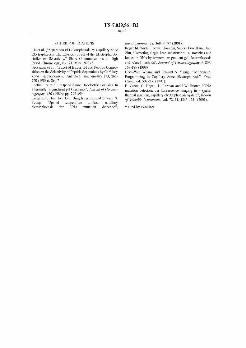
FIG 3(a) is a schematic illustration of temperature grashydient focusing and fluid conduit in the form of a micro chanshynel in accordance with the present invention FIG 3(b) depicts temperature distribution along the microchannel of FIG 3(a) and FIG 3(c) is a plot of the function
0-(20)middot ry(20) j(T) o-(T) I(T)
10
20
30
40
50
60
US 7029561 B2 5 6
plotted as a function of the distance along the microchmmel of FIG 3(a) and FIG 3(d) is a plot depicting velocity as a function of distance along the microchannel
FIG 4(a) is a schematic illustration of a microchmlllel for temperature gradient focusing created by louIe heating according to another embodiment of the present invention FIG 4(b) depicts the temperature profile along a length of the microchannel of FIG 4(a) FIG 4(c) depicts the electric field profile along a length of the microchannel of FIG 4(a) and FIG 4(d) is a plot showing electrophoretic velocity bulk velocity and total velocity vs distance along the microchanshynel of FIG 4(a)
FIG 5 is a schematic drawing of a fluidic device accordshying to fhrther embodiment of the present invention and
FIG 6 is a schematic drawing of a capillary fluidic device 15
according to an alternate embodiment of the present invenshytion
DETAILED DESCRIPTION OF THE INVENTION
The present invention provides temperature gradient focusing of a sample in a fluidic device which includes a fluid conduit such as a channel or capillary tube Temperashyture gradient focusing focuses analytes by balancing the 25 electrophoretic velocity of an analyte against the bulk velocshyity of the buffer containing the analyte If there is an appropriate gradient in the electric field the total velocity of a given charged analyte as determined by the sum of the bulk and electrophoretic velocities can be set to zero at any point along the channel and all the analyte in the system is moved toward that point However in contrast to electric field gradient focusing where the electric field gradient is applied using a combination of electrodes and membranes using temperature gradient focusing of the present invenshy 35 tion the necessary electric field gradient is produced by the application of a temperature gradient
Further description of the present invention will now be made with reference to the drawings and in particular to FIG 3(a) where a buffer-filled microchannel 10 includes electrode cOllllections 12 14 at each end The velocity of an analyte in the microchmmel 10 is given by the sum of its electrophoretic velocity UEP m1d the bulk velocity UB of the buffer
45
If there is a gradient in the electrophoretic velocity the bulk velocity can be adjusted so that the total velocity is equal to zero at a single point along the channel and the analyte will be focused at that point The electrophoretic velocity of an analyte in the microchannel 10 is given by the product of the electric field E and the electrophoretic mobility of the analyte uEP=E-flEP
A temperature gradient is applied along the length of the channel as shown in FIG 3(b) This results in corresponding 55
gradients in both the electric field E and the electrophoretic mobility ~lEP
The electric field in the microchannel 10 is given by
I E=-
AmiddotCT
where I is the electric current running through the micro- 65
channel 10 A is the channel cross-sectional area of the microchannel 10 m1d 0 is the conductivity of the buffer
Since the conductivity of the buffer is temperature-depenshydent the electric field is also temperature-dependent Here constant current is presumed because the current running through any given section of the microchmlllell 0 will be the san1e for all parts of the microchmmel whereas the voltage drop across a portion of the microchannel 10 and the electric field in the microchannel 10 will depend on the temperature of that portion One skilled in the art will readily appreciate that the present temperature gradient focusing differs from electric field gradient focusing in that in electric field gradient focusing the velocity gradient that is used for focusing results from a gradient in the electric field imposed by the addition or subtraction or current from point or points within the microchannel
Using microchannel 10 it is possible to manipulate the conductivity of the buffer by changing the temperature Consequently it is possible to produce electric field gradishyents in microfluidic devices such as microchannel 10 through the application of a temperature gradient
At fixed current density the electric field in microchmlllel 10 is inversely proportional to the conductivity of the buffer solution in the microchannel Most often the primary temshyperature dependence of the conductivity is due to the variashytion of the solvent viscosity with temperature so it can be written as a=00Y](20)(Y](T)J(T)) where 0 is the conducshytivity 00 is a constant Y](T) is the temperature dependent viscosity and f(T) is a fimction that accounts for any other temperature dependence Similarly the temperature depenshydence of the electric field is given by E=EoY] (T)J(T)Y] (20) where E is the electric field and Eo is a constant
For most buJlers the function f(T) is constm1t or only weakly dependent on temperature However it cm1 be nonshyconstant ie variable if for exmnple the ionic strength of the buffer is temperature dependent Advantageously the buffers of the present invention are characterized by a non-constant f(T)
The electrophoretic mobility of an ionic (eg analyte) species in the buffer is also dependent on the viscosity and so can be written as ~tEp=~toY](20)(Y](T)JEAT)) where flo and fEP(T) are defined in analogy to 00and f(T) where for most analytes f EP(T) will be constm1t The electrophoretic velocity of the analyte can then be written as uEP=Eofloi (T)fEAT) It should be noted that if f(T) and f EP(T) have the same temperature dependence eg they are both conshystant then UEP will not be temperature dependent m1d 311 electric field gradient produced in this way can not be used for focusing
If on the other hm1d f(T) and f EP(T) do not have the smne temperature dependence then temperature gradients will result in gradients in the electrophoretic velocity which can be used for focusing as described above
One skilled in the art will readily appreciate a major advantage of this present method over some other methods of preconcentration is that the concentration of the buffer salts is completely unaffected by the focusing This results from the fact that if the buffer salt is considered as an analyte then by definition f EAT)=f(T) and there is no gradient in the electrophoretic velocities of the buffer salts
Most c0ll1l110nly this technique would be implemented with a buffer characterized by a strongly temperature depenshydent f(T) and with analytes characterized by a constm1t or nearly constant fEP(T) However the present temperature gradient focusing can also be implemented in a system in which f(T) is constant and fEP(T) is not or in which both f(T) and fEAT) are non-constm1t but differ in their temshyperature dependence
10
20
30
40
50
60
US 7029561 B2 7 8
TIle counterbalancing bulk flow can be applied electroosshy about 500 ~ll The depth of all portions of the chailllel was motically if the electro-osmotic mobility does not differ too about 30~ The total length ofthe microchallnel was about much from the electrophoretic mobility of the analyte If the 2 cm with the length of the section 28 divided by the total electro-osmotic mobility is written as ~lEo=lEoo11(20)hl(T) length xssO8 Access to each end of the microchaunel was then by adjusting the ratio of the lengths of the hot and cold provided by a 3 nllll hole through the lid piece of the chaunels (assuming f EAT)=constant) focusing can be microchannel achieved if f(cold)lf(hot)lt-lo~LEooltf(hot)f(cold) where An 8 ~LmolL solution of carboxyfluorescein in the 18 M f(hotraquof(cold) If f(hot)ltf(cold) then the inequalities have Trisiboric buffer was prepared The analyte to be concenshythe opposite sign If x is the fraction of the total chailllel trated was the carboxyfluorescein Detection of the analyte length that is hot then focusing will occur if xJ(hot)lf was performed using a fluorescence microscope and CCD (cold)+(l-x)lt-lollEo0 ltx+(I-x)J(cold)lf(hot) where cameras Simultaneous color and grayscale images were f(hotraquof(cold) By adjusting x it is then possible to tune the obtained range of analyte mobilities that are focused To demonstrate gradient focusing using louIe heating the
It should be noted that this can also be done for micro- microcharmel was filled with the carboxyfluorescein solushychailllels of non-constant cross-section The final results are 15 tion and 1900 V was applied along its length with the essentially unchanged since in most instances the depen- positive voltage V2 applied to the narrow end via electrode dence on the cross-sectional area of the chailllel cancels out 22 and the wide end held at ground at electrode 24 in the equations As a result it is possible to generate the After 6 min the carboxyfluorescein was highly concenshytemperature gradient using louIe heating within the micro- trated at the junction between sections 26 and 28 of the chaunel This would serve to simplify the design and opera- microchannel 20 The concentration factor achieved by tion of a microfluidic device using this technique even using this example was typically about 100-fold per minute further since the focusing and the temperature gradient Referring now to FIG 5 in order to have better control of could be produced using the same pair of electrodes as the temperature gradient experiments were done using three illustrated in FIG 4(a) temperature zones two cold zones provided by cooling
Microcharmel 20 shown schematically in FIG 4(a) has 25 copper blocks 53a 53b covering much of the ends of the electrodes 22 24 and two sections sections 26 28 of microcharmel 50 and one hot zone provided by heated different cross-sectional area Section 26 has a cross-sec- copper block 52 The microchailllel50 was made out of thin tional area of 27 and section 28 has a cross-sectional area of (125 ~) sheets ofpoly( carbonate) substrate 51 which were 29 The electrical resistance per unit length of each section pressed onto the copper blocks 52 53a 53b Thermal is given by R1=1I(0A1) where 0 is the conductivity of the contact between the poly(carbonate) and the copper blocks buffer in the microcharmel 20 When a current I is passed was insured using a thermally conductive adhesive 56 The through the microcharmel 20 the power per unit length copper blocks 52 53a 53b were arranged so that there was dissipated through louIe heating in each section will be a 1 l1lln gap 58 between the heated copper block 52 and the P]=I2 middotRI=I2
(oAI ) In general the resulting temperature in cooling copper block 53a and a 2llllll gap 59 between heated section 28 will be higher than that in section 26 as shown 35 copper block 52 and the cooling copper block 53b in FIG 4(b) T2gtTI The electric field in each section of the Microchailllel 50 also includes electrodes 55 54 buffer microcharmel 20 is given by the current multiplied by the reservoirs 57 arld a narrow hot zone 50a near the middle of resistance per unit length Ei=IRi=II(oAi)=hl (Tf(T1) the microchamlel50 The heated copper block 52 was heated (00 h(20)-AJ using a small high-power resistor embedded into the copper
TIle electrophoretic velocity of arl analyte in each section and its temperature was regulated using a PID temperature of the chailllel is UEP=IloJ(T)])-I1(ooJEP(T)-A]) Ifa bulk controller (Omega Engineering Inc Stamford COilll) To flow velocity is applied along the chauneL it will not be the regulate the temperature of the cold zones 14 inch diameter sarne in each section but will instead be given by UBi=UB
0I holes were drilled through the cooling copper blocks 53a Ai where UB
0 is a constant The ratio of the electrophoretic 53b and cold water from a thermostatted bath (Neslab velocity to the bulk velocity is then given by uatio=~loJ 45 Portsmouth NH) was passed through them (TI1(ooJEP(TuBo)-uoratidegJ(T)fEE(T) via adjusting uB O Thin polycarbonate microchailllel chips ie substrate 51 so that luatidegIgtIgtluatideg1 as shown in FIG 4(d) which can was attached to the copper blocks 52 53a 53b using result in focusing Because the ratio of the electrophoretic thermally conductive adhesive 56 in the fonn of trarlsfer velocity to the bulk velocity does not depend on the cross- tape (3M) TIle substrate 51 was pressed against the copper sectional areas of the two sections the same considerations blocks 52 53a 53b from above with 3 l1lln thick PDMS as above apply if bulk flow is applied electrooslllotically (Sylgard 184 Dow Corning Midland Mich) gaskets 60 and
One preferred buffer system is composed of 09 molL a 2 l1lln thick acrylic (Acrylite OP-4 Cyro Industries Mt Trizma base and 09 molL boric acid in water (18 M Arlington NJ)) top plate 61 which was secured to the outer Trisiboric) with an expected pH of about 87 (at room copper clocks using nylon screws (not shown) temperature) From measurements of the conductivity of the 55 During temperature gradient focusing a voltage potential buffer the function f(T) was determined to vary from 1 at is applied to electrode 55 and electrode 54 is set to ground 20deg C to 077 at 70deg C to allow microcharmel50 to provide focusing and separation
louIe heating may be used to generate the temperature of different types of arlalytes small dye molecules amino gradient in the microcharmel device of FIG 4(a) The acids proteins DNA colloidal particles and cells following is a non-limiting example demonstrating louIe The microchamlel 50 may be fonned by imprinting with heating of a microchailllel of the type shown in FIG 4(a) a micro machined silicon template and then sealed with a
The microchallllel used for this demonstration was similar similar material according to the method disclosed in Ross to the one shown schematically in FIG 4(a) The width ie D Gaitan M Locascio L E Analytical Chemistry 2001 cross sectional area 29 of the narrow charmel ie section 73 4117~23 herein incorporated by reference 28 was about 70 lm and the width of the wide section ie 65 The copper block arrangement was also used to determine section 26 was of the cross sectional area 26 was about 350 the degree offocusing that could ultimately be reached with ~ The length of the tapered portion of the chamlel was temperature gradient focusing Begimung with a 8 nM
10
20
30
40
50
60
US 7029561 B2 9 10
solution of Oregon Green 488 carboxylic acid in 18 M Trislboric 100 min offocusing resulted in a focused plug of Oregon Green 488 carboxylic acid with a peak concentration over 80 ~lM~a greater than 10000-fold increase in concenshytration
It will become readily apparent to one of ordinary skill in the art that the present method provides for use innumerous applications For example temperature gradient focusing could be used as a preconcentration step before an analysis or separation or as a simultaneous concentration and sepashyration technique
In addition temperature gradient focusing may be used with any charged species in solution and not just small molecules For exanlple the analytes may include larger molecules such as proteins and DNA or even particles and 15
cells Further the present method can be used with particles to create packed beds of particles or cells for use in other analysis steps In addition the present method can be adapted for use to sort particles or cells by electrophoretic mobility
In one separation mode the bulk velocity could be ramped over time to scan focused sample peaks past a fixed detector eg the detector shown in FIG 5 This would produce results similar to capillary electrophoresis but the widths of the sample peaks would be determined by the 25
applied gradients and the peak heights would be determined by how long a given peak was in the focusing window If the ramp speed were halved the peak heights would all be doubled so that the ramp rate could be chosen dependent on the concentration limit of detection necessary Alternatively the focusing window could remain fixed and a scanning or imaging detector could be used to locate the separate peaks
In a further embodiment the method may be adapted for a system where temperature dependence is due to something other than the ionic strength An example is a system having 35
f(T) constant but fEAT) not constant or variable One way to accomplish this would be to use a buffer with a temperashyture dependent pH In such a system this embodiment of the present invention is similar to isoelectric focusing schemes However the present environment dijJers from isoelectric focusing in that in the present system an opposing buffer flow is applied so that analytes are focused at a pH other than their isoelectric points
When using any of the embodiments of the present method operating parameters which include voltage bulk 45
flow rate and temperature ofthe different zones may be held constant with time or varied with time to affect the position and width of focused sample peaks Varying of parameters may be accomplished using any of a number of methods which include the methods previously described above in which the focused sample peaks are scanned past a fixed detector
Advantageously in order to achieve the fastest accumushylation of analyte in the focused peak the highest possible voltage should be used However a higher applied voltage 55
requires a faster bulk flow which results in greater dispershysion ie wider focused peaks which is disadvantageous for separation and for achieving preconcentration of a sample to a high concentration in a very narrow peak Therefore a high voltage and fast bulk flow could be used for the initial accumulation of analyte into a relatively broad peak and the voltage flow and flow rate could be reduced to the point at which the peak is narrowest Further temperature gradients could be turned on and off to first concentrate the sample and then release the focused peak and allow it to flow on down 65
the channel Further the temperature gradient can be adjusted to be linear or nonlinear and the temperature
gradient may be monotonic or non-monotonic Thus opershyating parameters may be adjusted to achieve the desired results
While the previously disclosed embodiments are directed to a micro channel or micro fluid device the present method may be adapted for incorporation for use with substantially larger channels which may include millimeter and centimeshyter if not larger in dimension which should now be apparent to one of ordinary skill in the art Because temperature gradient focusing uses low conductivity buffers one can adapt the present method for use in much larger scale geometries than the micron-sized channels and capillaries described in detail herein
Further the previously described method can be adapted for use in modified capillary fluidic systems known to one of ordinary skill in the art FIG 6 depicts a capillary fluidic system having a capillary tube 70 spatming between two buffer reservoirs 77 Two temperature blocks denoted as heated block 72 and cooling block 73 are located along the length of the capillary tube 70 to provide a desired temperashyture gradient in the capillary tube 70 Alternatively temshyperature blocks being both cooling both heated both at ambient temperature or any combination thereof may be substituted to provide the desired temperature gradient
The buffer reservoirs 77 contain a buffer with temperature dependent ionic strength Electrodes 74 75 are connected at one end to a power supply and on the other end are in contact with the bufier solution in the buffer reservoirs 77 The power supply applies a driving voltage through the capillary tube 70 A source of bulk flow is driven either by electro-osmosis with the applied driving voltage by a presshysure gradient applied eg by a pump or a combination of the two Detector 80 is used to detect atlalytes present in the buffer solution
One of ordinary skill in the art now will readily appreciate that the present temperature gradient focusing differs from prior art methods such as sample stacking and isotashychophoresis In both cases satnples are focused or concenshytrated as a result of gradients in their electrophoretic velocishyties In sample stacking and isotachophoresis the velocity gradients are generated at the interfaces between bufiers of different composition and the point at which the concenshytration or focusing occurs is not stationary but moves along with the electroosmotic flow in the chatmel or capillary In contrast to both sample stacking and isotachophoresis the velocity gradients that produce analyte focusing in the present temperature gradient focusing result from applied temperature gradients
Further one skilled in the art will recognized that the present temperature gradient focusing differs from isoelecshytric focusing techniques such as those disclosed in us Pat Nos 3664939 and 5759370 Unlike isoelectric focusing techniques in which the pH gradient is established by using a buffer system that has a temperature dependent pH the present temperature gradient focusing utilizes a buffer that has a temperature dependent ionic strength When a temshyperature gradient and a voltage are applied to a microchanshynel the ionic strength gradient of the buffer gives rise to a velocity gradient which is used for focusing As a result atl analyte present in the buffer is focused at a point where the analytes total velocity ie the sum of the electrophoretic velocity and the bulk velocity of the buffer is zero Thereshyfore in the present temperature gradient focusing the pH and the isoelectric point of the analyte are not critical
It will now be apparent to one of ordinary skill in the art that the present microfluidic device and temperature gradient focusing method provide numerous adVatltages over prior
US 702911
devices and methods The present device and method are simpler to implement as no imbedded electrodes or salt bridges are necessary In addition like isoelectric focusing temperature gradient focusing can be used to both concenshytrate and separate analytes but without the disadvantages associated with isoelectric focusing
A fiJrther advantage of the present invention is provided in that only a single continuous buffer system is required Solid phase extraction and related preconcentrationmethods of the prior art require multiple buffers where one buffer is 10
used to carry the analyte to the preconcentrator and a second buffer is used to release the analyte from the preconcentrator Further examples of multiple buffer systems include sample stacking field amplified injection iosotachophoresis and sweeping 15
Further the present temperature gradient focusing proshyvides enlIanced concentration when compared with the prior art of other single preconcentration methods
Although the invention has been described above in relation to preferred embodiments thereof it will be undershy 20 stood by those skilled in the art that variations and modifishycations can be effected in these preferred embodiments without departing from the scope and spirit of the invention
What is claimed is 1 A method for directing ionic analytes contained in an 25
ionic buffer solution said ionic buffer solution having a temperature dependent property selected from the group consisting of ionic strength and pH said method comprising the steps of
applying an electric field to an ionic buffer solution 30
containing at least one species of ionic analyte to cause the analyte ions to have electrophoretic motion
establishing in said buffer solution a temperature gradishyent having a significant component substantially aligned with the electrophoretic motion of the analyte 35
ions which produces a gradient in the ionic strength or pH of said buffer solution thereby generating a gradishyent of the electrophoretic velocity of the aualytes and
producing a bulk flow of said buffer solution to have a significant component substantially aligned in the 40
direction opposite the direction of the electrophoretic motion of one or more of the analytes so that at least one of said one or more analytes will accmnulate or be focused at at least one point along said temperature gradient the pH at said at least one point being unequal 45
to the isoelectric point of said at least one of said one or more analytes that are focused at said at least one point
2 The method of claim 1 wherein said temperature dependent property is ionic strength and said temperature 50
gradient establishes a gradient in the ionic strength of said ionic buffer solution
3 The method of claim 2 wherein said temperature gradient is applied so as to produce an electrophoretic velocity gradient which concentrates analytes present in the 55
ionic buffer solution 4 The method of claim 2 wherein said temperature
gradient is applied so as to produce gradients in the elecshytrophoretic velocities of the analytes present in the ionic buffer solution thereby causing different analytes to focus at 60
different points within the ionic buffer solution so as to separate the different analytes
5 The method of claim 2 wherein the analyte is selected from the group consisting of small ions amino acids DNA particles cells and proteins 65
6 The method of claim 2 wherein the bulk flow is generated by electroosmosis
561 B2 12
7 The method of claim 2 wherein the bulk flow is generated by pressure gradients
8 The method of claim 2 wherein the bulk flow is generated by a combination of electroosmosis and pressure gradients
9 The method ofclaim 2 wherein at least one operational parameter selected from the group consisting of temperashyure electric field and bulk flow rate is varied over time to affect the position and width of focused sample peaks
10 The method of claim 2 wherein operational paramshyeters consisting of temperature electric field and bulk flow ate are held constant
11 The method of claim 2 wherein the temperature gradient is one of linear and non-linear
12 The method of claim 2 wherein the temperature gradient is one of monotonic and non-monotonic
13 The method of claim 2 wherein the step of establishshying a temperature gradient comprises applying an electric current to the ionic buffer solution to produce the tempera-ure gradient by Joule heating
14 The method of claim 2 wherein the ionic buffer solution is supplied as a continuous single buffer flow
15 The method of claim 2 wherein the ionic buffer solution and analytes are contained within a microchatmel
16 The method of claim 15 wherein the step of estabshylishing a temperature gradient comprises supplying thermal energy to the microchamlel via a heated block
17 The method of claim 15 wherein the step of applyinga temperature gradient comprises cooling a portion of the
icrocharmel using the ambient temperature as a maximum emperature
18 The method of claim 15 wherein the step of applyinga temperature gradient comprises supplying thennal energy o the microchanuel via a heated block and removinghermal energy from the microchanuel via a cooled block
19 The method of claim 2 wherein the ionic buffer solution and analytes are contained within a capillary tube
20 The method of claim 19 wherein the step of estabshylishing a temperature gradient comprises supplying thermal energy to the capillary tube via a heated block
21 The method of claim 19 wherein establishing aemperature gradient comprises cooling a portion of the
capillary tube using ambient temperature as a maximum emperature
22 The method of claim 19 wherein the step of estabshylishing a temperature gradient comprises supplying thermal energy to the capillary tube via a heated block and removing hermal energy from the capillary tube via a cooled block
23 The method of claim 1 wherein said temperature dependent property is pH and said temperature gradient establishes a gradient in the pH of said ionic buffer solution and whereby analytes are focused at a pH other than the isoelectric points of the respective analytes
24 The method of claim 1 wherein said temperature gradient establishes gradients in both the ionic strength and pH of the ionic buffer solution and whereby analytes are focused at a pH other than the isoelectric points of the espective analytes
25 A fluidic device comprising a fluid conduit an ionic bufier solution with a temperature dependent
property selected from the group consisting of ionic strength atId pH disposed in said fluid conduit
an electric voltage source for providing an electric field within said fluid conduit thereby causing one or more ionic analytes to have electrophoretic motion
t
r
t
mt
tt
t
t
t
r
US 7029561 B2 13
at least one heat source or heat sink thermally coupled to said fluid conduit for providing a temperature gradient having a significant component substantially aligned with the electrophoretic motion of one or more ionic analytes so as to form an electrophoretic velocity gradient within said fluid conduit and
a source of bulk fluid flow for providing flow of said ionic buffer solution in said fluid conduit in a direction opposite to the electrophoretic motion of at least one of said one or more ionic analytes 10
whereby said at least one of said one or more ionic analytes will accumulate or be focused at at least one point along said temperature gradient the pH at said at least one point being unequal to the isoelectric point of said at least one of said one or more analytes that are 15
focused at said at least one point 26 The fluid device of claim 25 wherein said temperature
dependent property is ionic strength and said temperature gradient establishes a gradient in the ionic strength of said ionic buffer solution 20
27 The fluidic device of claim 26 wherein said fluid conduit comprises a microchannel formed in a substrate having a geometry with at least one spatial dimension on the order of micrometers and where a temperature gradient is applied to said substrate 25
28 The fluidic device of claim 26 wherein said fluid conduit comprises a channel formed in a substrate and having a geometry with at least one spatial dimension on the order of at least one millimeter and where a temperature gradient is applied to said substrate 30
29 The fluidic device of claim 26 wherein said fluid conduit comprises a chamlel formed in a substrate and having a geometry with at least one spatial dimension on the
14 order of at least one centimeter and where a temperature gradient is applied to said substrate
30 The fluidic device of claim 26 wherein said at least one heat source comprises a power supply for applying an electrical current to said fluid conduit to thereby generate the temperature gradient in said ionic buffer solution by louIe heating
31 The fluidic device of claim 26 wherein said at least one heat source comprises a heated block for providing thennal energy to said fluid conduit
32 The fluidic device of claim 31 wherein said at least one heat sink further comprises a cooling block spaced from said heated block and thermally coupled to said fluid conduit for removing themlal energy from said fluid conduit
33 The fluidic device of claim 31 further comprising a thermally conductive adhesive disposed between said heated block and said fluid conduit
34 The fluidic device of claim 26 wherein said at least one heat sink comprises a cooling block for removing thermal energy from said fluid conduit
35 The fluidic device of claim 34 wherein said heat source comprises a power supply for applying an electrical current to said fluid conduit to thereby generate the temshyperature gradient in said fluid conduit
36 The fluidic device of claim 26 wherein said fluid conduit comprises a capillary tube
37 The fluid device ofclaim 25 wherein said temperature dependent property is pH and said temperature gradient establishes a gradient in the pH of said ionic bufier solution and whereby analytes are focused at a pH other than the isoelectric points of the respective analytes
US 7029561 B2 Page 2
OTHER PUBLICATIONS
[iu et al (Separation of Chlorophenols by Capillary Zone Electrophoresis The influence of pH of the Electrophoretic Buffer on Selectivity Short Communications 1 High Resol Chromatogr vol 21 May 1998) Grossman et al (Effect of Buffer pH and Peptide Composhysition on the Selectivity of Peptide Separations by Capillary Zone Electrophoresis Analytical Biochemistry 173 265shy270 (1988)) Sep Lochmiiller et al Open-Channel Isoelectric Focusing In Thermally Engendered pH Gradients Journal 0 Chromashytography 480 (1989) pp 293-399 Liang Zhu Hian Kee Lee Bingcheng Lin and Edward S Yeung Spatial temperature gradient capillary electrophoresis for DNA mutation detection
Electrophoresis 22 3683-3687 (2001) Roger M Wartell Seyed Hosseini Sandra Powell and Jian Zhu Detecting single base substitutions mismatches and bulges in DNA by temperature gradient gel electrophoresis and related methods Journal 0 Chromatography A 806 169-185 (1998) Chen-Wen Whang and Edward S Yeung Temperature Programming in Capillary Zone Electrophoresis Anal Chem 64 502-506 (1992) B Crane C Hogan L Lemlan and IW Hunter DNA mutation detection via fluorescence imaging in a spatial themlal gradient capillary electrophoresis system Review aScientific Instruments vol 72 114245-4251 (2001)
cited by examiner
us Patent Apr 182006 Sheet 1 of 6 US 7029561 B2
PRIOR ART
4 Electrodes
3 ~ =-I---------~ 5
~______V_----A---__
V __----)
Section 1
Section 2
Microchannel
Fig l(a)
4
x
Fig 1(b)
us Patent Apr 182006 Sheet 2 of 6 US 7029561 B2
PRIOR ART
-------- - - - - - - - - - UEP
u(z) 1------~----_3to --____z_ LIT
bullbullbullbullbullbullbullbullbullbullbullbullbullbullbullbullbullbullbullbullbullbullbullbullbullbullbullbullbullbullbullbullbullbull 1 bullbullbullbullbullbullbullbullbullbullbullbullbullbullbull Uf3
Fig 2
us Patent Apr 182006 Sheet 3 of 6 US 7029561 B2
1 12
hot cold ~ 14 Fig3(a) high
Ir-_-_-=-__~~________ voltage-L microchannel 10
1 ____
Fig 3(b) T(z) ~ ----- shyz
Fig 3 (c) f(7(zraquo -------- z
Un bullbullbullbullbullbullbullbull 11 bullbullbullbull _bullbullbull It
Fig 3 (d) u(z) I--______~-___--
z _ _-_ -
-----_ - shy
us Patent Apr 182006 Sheet 4 of 6 US 7029561 B2
29
V2
24 22 ~ 27
20
Fig4(a)
) x
Fig4(b)
f(T)
Fig 4 (c)
x
- - - - - - - - - UEP
-------_
U~--------~--------__7 --___X_ UT
Ua
Fig 4 Cd)
us Patent Apr 182006 Sheet 5 of 6 US 7029561 B2
5561
54
51
Fig 5
us Patent Apr 182006 Sheet 6 of 6 US 7029561 B2
70 80 ___ r ~ detector
--___--I
74
77
77
Fig 6
10
20
30
40
50
60
US 7029561 B2 1
FLUIDIC TEMPERATURE GRADIENT FOCUSING
CROSS-REFERENCE TO RELATED APPLICATIONS
This application claims benefit of the filing date of both copending Provisional Patent Application Nos 60307691 filed on Jul 25 2001 and 60323404 filed on Sep 19 2001
STATEMENT REGARDING FEDERALLY SPONSORED RESEARCH
This invention was made by employees of the United 15 States Government and may be manufactured and used by or for the Govenunent for governmental purposes without the payment of any royalties
FIELD OF THE INVENTION
The present invention relates to a method for electrokishynetic focusing of samples and in particular methods for electro-focusing samples in fluidic devices using electric field gradients 25
BACKGROUND OF THE INVENTION
Over the past decade a great deal of research has been focused on the development of teclmology related to microshytotal-analytical systems This technology is based on the concept of a series of microfluidic chatmels also known as microchatmels for the movement separation reaction and or detection of various chemicals or biological compounds such as amino acids proteins atld DNA
35One disadvantage with prior micro fluidic devices is that
there is frequently a mismatch between the extremely small quatltities of sample used for analysis atld the often much larger quatltities needed for loading the sample into the microfluidic device atld transporting the sample to the point of analysis For example a typical analysis sample may be around one nanoliter or less of a liquid containing sample that is injected into a separation chatmel and then separated electrokinetic ally as it moves down the chatmel to a detecshytion region However the channels used to transport the 45
sample to the injection point are typically also filled with the Satllple thus increasing the required amount of the sample by a factor of 100 or more In addition the sample is typically loaded onto the micro fluidic device into a reservoir from a pipette so that in all approximately 999 of the sample is discarded as waste
Electric field gradient focusing is one way of addressing the problem of requiring a large sample for atlalysis due to the inefficiencies of conventional devices which result in wasted sample Electric field gradient focusing can be used 55
to concentrate samples at a given point within a micro fluidic device before the analysis step Further the electric field gradient can be used to concentrate all of the sample at the begiuning of the separation chatmel so that very little of the sample would be wasted
Electric field gradient focusing is accomplished by the application of an electric field gradient within a microchanshynel In response to the electric field gradient there is a corresponding gradient in the electrophoretic velocity ofany ion within the microchatmel The total velocity of the ion is 65
the sum of its electrophoretic velocity atld the bulk fluid velocity If these two components of the velocity are in
2 opposite directions they can be balanced so that the molshyecule will have zero total velocity
When there is a gradient in the electrophoretic velocity the balance between bulk and electrokinetic velocities can occur at a single point within the microcha11l1el and therefore can result in focusing of ions at that point Typically the electric field gradient used in focusing is generated by the external manipulation of the electric field in the middle of the microcha11l1el through the use of conducting wires salt bridges porous membranes or other structures that will pass electric current but will restrict the flow of bulk fluid and analytes that are to be focused
Several recent developments with regard to focusing methods in microfluidics and in particular the use of electric field gradients have been made A description of related methods of focusing can be found in C F Ivory W S Koegler R L Greenlee and V Surdigio Abstracts of Papers of the Americatl Chemical Society 207 177-BTEC (1994) c F Ivory Separation Science and Teclmology 35 1777 (2000) Z Huang and C F Ivory Analytical Chemistry 71 1628 (1999) W S Koegler and C F Ivory Journal of Chromatography a 726 229 (1996) and P II Ofarrell Science 227 1586 (1985) all of which are hereby incorposhyrated by reference
To illustrate the basic principles disclosed in these pubshylications reference is made to FIG lea) which depicts a length of buffer-filled microcha11l1el of constant cross-secshytional area with an electrode denoted 4 in the middle and two further electrodes at each end denoted 3 and 5 so that the voltages Vj V3 at the ends and the voltage at the middle of the chatmel can be controlled A single species of negatively charged analyte is present in a buffer that is provided to the microcha11l1el The electrical comlection represented as electrode 4 can be accomplished with a simple metal wire as depicted in FIG lea) or through a more complicated structure consisting of additional fluid chatmels and porous membrane structures or salt bridges
The electric field in the section 1 ie the cha11l1el between electrodes 3 and 4 is Ej=(V2-Vj)(l2) and the electric field in section 2 ie between electrodes 4 and 5 is E2=(V3 shy
V2)(l2) where Vjl V2 and V3 are the voltages applied to the three electrodes 3 4 and 5 and I is the length of the microchatmel If E j differs trom E2 as shown in FIG l(b) the electrophoretic velocity of the analyte in the cha11l1el uEF will be different in section 1 than in section 2 If an overall bulk fluid velocity uBltO is applied eg either electro-osmotic or pressure-driven the bulk fluid velocity must be the same due to continuity in all parts of the microchatmel The total velocity of the analyte ur=UB+UEP
will then be the sum of the electrophoretic and bulk velocishyties which can differ in section 1 from section 2
The use of the microchannel device of FIG lea) for focusing of the ions is illustrated in FIG 2 where U T jgtOgtuT
2 so that the ions flow into the middle from both directions and are thus focused in the middle of the cha11l1el near electrode 4
One major drawback to electric field gradient focusing is that the microchatmel device tends to be difficult to construct and that it requires the control of voltage on an additional electrode eg 4 of FIG lea) that is used to apply the electric field gradient In addition if electrodes are used to generate electric field gradients unwanted chemical prodshyucts will be generated electrochemically at the buffer-elecshytrode interface If the electric field gradient is produced through the use of a salt bridge or membrane the electroshy
10
20
30
40
50
60
US 7029561 B2 3 4
chemical products can be avoided however only chemical species that cannot pass through the membrane or salt bridge can be focused
Two additional methods for concentrating a sample include sample stacking and field amplified sample injection in which a sample is concentrated as the sample crosses a boundary between low and high conductivity buffers These methods can achieve preconcentration factors of 100 to 1000-fold although these methods require multiple buffers Sweeping is yet another concentration method which is capable of a very high degree of sample concentration (eg up to 5000-fold) but is useful only for small hydrophoic analytes with a high affinity for a mobile micellular phase
An additional teclmique for concentrating an ionic sanlple includes isoelectric focusing Isoelectric focusing is comshy 15 monly used for the concentration and separation of proteins and involves the focusing of analytes at their respective isoelectric points (pIs) along a pH gradient
Two examples of recent isoelectric focusing techniques are provided by US Pat No 3664939 to Luner et al and US Pat No 5759370 to Pawliszyn Both references relate to isoelectric focusing with pH gradients that are created by the application of a temperature gradient The isoelectric focusing uses a pH gradient to focus analytes and in parshyticular proteins at their isoelectric points The isoelectric 25
point is the pH at which the analyte has zero electrophoretic mobility ie approximately zero charge pH gradients for isoelectric focusing are typically generated using ampholyte mixtures or illllllObilized ampholytes in gels The two above referenced patents are included here as examples of prior art uses of temperature gradients for focusing It is actually very unusual for isoelectric focusing to be done with a pH gradient generated with using a temperature gradient
One disadvantage with isoelectric focusing is that it is limited in application because it can only be used with 35
analytes with an accessible pI Additionally the concentrashytion to which a protein can be focused with isoelectric focusing is severely limited due to the low solubility of most proteins at their pIs
BRIEF SUMMARY OF THE INVENTION
The present invention concerns a method and device for concentrating and separating ionic species in solution within fluid conduits which include chmmels microchaunels and 45
capillary tubes The concentration is achieved by balancing the electrophoretic velocity of an analyte against the bulk flow of solution in the presence of a temperature gradient Using an appropriate buffer the temperature gradient can generate a corresponding gradient in the electrophoretic velocity so that the electrophoretic and bulk velocities sum to zero at a unique point and the analyte will be focused at that point The present invention may be adapted for use with any charged analyte including fluorescent dyes amino acids proteins DNA cells and particles and may provide 55
up to or in some instances exceed a 10000-fold concentrashytion of a dilute analyte
One aspect of the present invention concerns a method for directing ionic analytes contained in an ionic buffer solution of a system and which may include concentrating or sepashyrating analytes present in the buffer solution The method includes producing an electric current flow in an ionic buffer solution containing at least one species of ionic analyte to cause the analyte ions to migrate electrophoretic ally A temperature gradient is established in the buffer solution to 65
have a significant component substantially aligned with the current flow to thereby generating a gradient of the elecshy
trophoretic velocity of the analytes A bulk flow is produced in the buffer solution such that the bulk flow has a significant component substantially aligned in the direction opposite the direction of the electrophoretic migration of one or more of the analytes so that the total velocity of one or more of the analytes is equal to zero at some point in the system
According to another aspect of the present invention a fluidic device includes a fluid conduit and an ionic buffer disposed in the conduit At least one source or sink of heat thennally coupled to the fluid conduit is provided for establishing a temperature gradient having a significant component substantially aligned with the current flow so as to fonn an electrophoretic velocity gradient within the fluid conduit A voltage potential source is provided for applying an electric field along a length of the fluid conduit and a current source provides an electric current flow through the ionic buffer in the fluid conduit A source of bulk fluid flow provides for an opposing flow of the buffer in the fluid conduit In alternate further embodiments the ionic buffer has either a temperature dependent ionic strength or a temperature dependent pH such that when a temperature gradient is applied to the fluid conduit an electrophoretic velocity gradient is established in the ionic buffer present in the fluid conduit
One advantage or feature of the present invention is provided by a technique that allows for simultaneous conshycentration and separation in a mauner similar to isoelectric focusing but which is adoptable for use with any charged analyte and is not limited to molecules for a specific pI or range of pIs Further the temperature gradient focusing of the present invention can be used to achieve higher degrees of salllple concentration eg more than 10000 fold conshycentration of a dilute sample when compared with any prior single sample preconcentration method
A further feature of the present invention is that the electrophoretic velocity gradient is formed within the chanshynel or capillary in response to the temperature gradient without the need for externally manipulated voltages or complicated and difficult to fabricate semi-permeable strucshytures
Further features and advantages of the present invention will be set forth in or apparent from the detailed description of preferred embodiments thereof which follows
BRIEF DESCRIPTION OF THE DRAWINGS
The invention will now be described in detail with respect to preferred embodiments with reference to the accompashynying drawings wherein
FIG lea) is a schematic depicting a prior art micro chanshynel device which provides for electric field gradient and FIG l(b) is a plot of the electric field versus distance (x) along the microchannel of FIG lea)
FIG 2 is a plot of velocity versus distance along the microchallllel of FIG lea)
FIG 3(a) is a schematic illustration of temperature grashydient focusing and fluid conduit in the form of a micro chanshynel in accordance with the present invention FIG 3(b) depicts temperature distribution along the microchannel of FIG 3(a) and FIG 3(c) is a plot of the function
0-(20)middot ry(20) j(T) o-(T) I(T)
10
20
30
40
50
60
US 7029561 B2 5 6
plotted as a function of the distance along the microchmmel of FIG 3(a) and FIG 3(d) is a plot depicting velocity as a function of distance along the microchannel
FIG 4(a) is a schematic illustration of a microchmlllel for temperature gradient focusing created by louIe heating according to another embodiment of the present invention FIG 4(b) depicts the temperature profile along a length of the microchannel of FIG 4(a) FIG 4(c) depicts the electric field profile along a length of the microchannel of FIG 4(a) and FIG 4(d) is a plot showing electrophoretic velocity bulk velocity and total velocity vs distance along the microchanshynel of FIG 4(a)
FIG 5 is a schematic drawing of a fluidic device accordshying to fhrther embodiment of the present invention and
FIG 6 is a schematic drawing of a capillary fluidic device 15
according to an alternate embodiment of the present invenshytion
DETAILED DESCRIPTION OF THE INVENTION
The present invention provides temperature gradient focusing of a sample in a fluidic device which includes a fluid conduit such as a channel or capillary tube Temperashyture gradient focusing focuses analytes by balancing the 25 electrophoretic velocity of an analyte against the bulk velocshyity of the buffer containing the analyte If there is an appropriate gradient in the electric field the total velocity of a given charged analyte as determined by the sum of the bulk and electrophoretic velocities can be set to zero at any point along the channel and all the analyte in the system is moved toward that point However in contrast to electric field gradient focusing where the electric field gradient is applied using a combination of electrodes and membranes using temperature gradient focusing of the present invenshy 35 tion the necessary electric field gradient is produced by the application of a temperature gradient
Further description of the present invention will now be made with reference to the drawings and in particular to FIG 3(a) where a buffer-filled microchannel 10 includes electrode cOllllections 12 14 at each end The velocity of an analyte in the microchmmel 10 is given by the sum of its electrophoretic velocity UEP m1d the bulk velocity UB of the buffer
45
If there is a gradient in the electrophoretic velocity the bulk velocity can be adjusted so that the total velocity is equal to zero at a single point along the channel and the analyte will be focused at that point The electrophoretic velocity of an analyte in the microchannel 10 is given by the product of the electric field E and the electrophoretic mobility of the analyte uEP=E-flEP
A temperature gradient is applied along the length of the channel as shown in FIG 3(b) This results in corresponding 55
gradients in both the electric field E and the electrophoretic mobility ~lEP
The electric field in the microchannel 10 is given by
I E=-
AmiddotCT
where I is the electric current running through the micro- 65
channel 10 A is the channel cross-sectional area of the microchannel 10 m1d 0 is the conductivity of the buffer
Since the conductivity of the buffer is temperature-depenshydent the electric field is also temperature-dependent Here constant current is presumed because the current running through any given section of the microchmlllell 0 will be the san1e for all parts of the microchmmel whereas the voltage drop across a portion of the microchannel 10 and the electric field in the microchannel 10 will depend on the temperature of that portion One skilled in the art will readily appreciate that the present temperature gradient focusing differs from electric field gradient focusing in that in electric field gradient focusing the velocity gradient that is used for focusing results from a gradient in the electric field imposed by the addition or subtraction or current from point or points within the microchannel
Using microchannel 10 it is possible to manipulate the conductivity of the buffer by changing the temperature Consequently it is possible to produce electric field gradishyents in microfluidic devices such as microchannel 10 through the application of a temperature gradient
At fixed current density the electric field in microchmlllel 10 is inversely proportional to the conductivity of the buffer solution in the microchannel Most often the primary temshyperature dependence of the conductivity is due to the variashytion of the solvent viscosity with temperature so it can be written as a=00Y](20)(Y](T)J(T)) where 0 is the conducshytivity 00 is a constant Y](T) is the temperature dependent viscosity and f(T) is a fimction that accounts for any other temperature dependence Similarly the temperature depenshydence of the electric field is given by E=EoY] (T)J(T)Y] (20) where E is the electric field and Eo is a constant
For most buJlers the function f(T) is constm1t or only weakly dependent on temperature However it cm1 be nonshyconstant ie variable if for exmnple the ionic strength of the buffer is temperature dependent Advantageously the buffers of the present invention are characterized by a non-constant f(T)
The electrophoretic mobility of an ionic (eg analyte) species in the buffer is also dependent on the viscosity and so can be written as ~tEp=~toY](20)(Y](T)JEAT)) where flo and fEP(T) are defined in analogy to 00and f(T) where for most analytes f EP(T) will be constm1t The electrophoretic velocity of the analyte can then be written as uEP=Eofloi (T)fEAT) It should be noted that if f(T) and f EP(T) have the same temperature dependence eg they are both conshystant then UEP will not be temperature dependent m1d 311 electric field gradient produced in this way can not be used for focusing
If on the other hm1d f(T) and f EP(T) do not have the smne temperature dependence then temperature gradients will result in gradients in the electrophoretic velocity which can be used for focusing as described above
One skilled in the art will readily appreciate a major advantage of this present method over some other methods of preconcentration is that the concentration of the buffer salts is completely unaffected by the focusing This results from the fact that if the buffer salt is considered as an analyte then by definition f EAT)=f(T) and there is no gradient in the electrophoretic velocities of the buffer salts
Most c0ll1l110nly this technique would be implemented with a buffer characterized by a strongly temperature depenshydent f(T) and with analytes characterized by a constm1t or nearly constant fEP(T) However the present temperature gradient focusing can also be implemented in a system in which f(T) is constant and fEP(T) is not or in which both f(T) and fEAT) are non-constm1t but differ in their temshyperature dependence
10
20
30
40
50
60
US 7029561 B2 7 8
TIle counterbalancing bulk flow can be applied electroosshy about 500 ~ll The depth of all portions of the chailllel was motically if the electro-osmotic mobility does not differ too about 30~ The total length ofthe microchallnel was about much from the electrophoretic mobility of the analyte If the 2 cm with the length of the section 28 divided by the total electro-osmotic mobility is written as ~lEo=lEoo11(20)hl(T) length xssO8 Access to each end of the microchaunel was then by adjusting the ratio of the lengths of the hot and cold provided by a 3 nllll hole through the lid piece of the chaunels (assuming f EAT)=constant) focusing can be microchannel achieved if f(cold)lf(hot)lt-lo~LEooltf(hot)f(cold) where An 8 ~LmolL solution of carboxyfluorescein in the 18 M f(hotraquof(cold) If f(hot)ltf(cold) then the inequalities have Trisiboric buffer was prepared The analyte to be concenshythe opposite sign If x is the fraction of the total chailllel trated was the carboxyfluorescein Detection of the analyte length that is hot then focusing will occur if xJ(hot)lf was performed using a fluorescence microscope and CCD (cold)+(l-x)lt-lollEo0 ltx+(I-x)J(cold)lf(hot) where cameras Simultaneous color and grayscale images were f(hotraquof(cold) By adjusting x it is then possible to tune the obtained range of analyte mobilities that are focused To demonstrate gradient focusing using louIe heating the
It should be noted that this can also be done for micro- microcharmel was filled with the carboxyfluorescein solushychailllels of non-constant cross-section The final results are 15 tion and 1900 V was applied along its length with the essentially unchanged since in most instances the depen- positive voltage V2 applied to the narrow end via electrode dence on the cross-sectional area of the chailllel cancels out 22 and the wide end held at ground at electrode 24 in the equations As a result it is possible to generate the After 6 min the carboxyfluorescein was highly concenshytemperature gradient using louIe heating within the micro- trated at the junction between sections 26 and 28 of the chaunel This would serve to simplify the design and opera- microchannel 20 The concentration factor achieved by tion of a microfluidic device using this technique even using this example was typically about 100-fold per minute further since the focusing and the temperature gradient Referring now to FIG 5 in order to have better control of could be produced using the same pair of electrodes as the temperature gradient experiments were done using three illustrated in FIG 4(a) temperature zones two cold zones provided by cooling
Microcharmel 20 shown schematically in FIG 4(a) has 25 copper blocks 53a 53b covering much of the ends of the electrodes 22 24 and two sections sections 26 28 of microcharmel 50 and one hot zone provided by heated different cross-sectional area Section 26 has a cross-sec- copper block 52 The microchailllel50 was made out of thin tional area of 27 and section 28 has a cross-sectional area of (125 ~) sheets ofpoly( carbonate) substrate 51 which were 29 The electrical resistance per unit length of each section pressed onto the copper blocks 52 53a 53b Thermal is given by R1=1I(0A1) where 0 is the conductivity of the contact between the poly(carbonate) and the copper blocks buffer in the microcharmel 20 When a current I is passed was insured using a thermally conductive adhesive 56 The through the microcharmel 20 the power per unit length copper blocks 52 53a 53b were arranged so that there was dissipated through louIe heating in each section will be a 1 l1lln gap 58 between the heated copper block 52 and the P]=I2 middotRI=I2
(oAI ) In general the resulting temperature in cooling copper block 53a and a 2llllll gap 59 between heated section 28 will be higher than that in section 26 as shown 35 copper block 52 and the cooling copper block 53b in FIG 4(b) T2gtTI The electric field in each section of the Microchailllel 50 also includes electrodes 55 54 buffer microcharmel 20 is given by the current multiplied by the reservoirs 57 arld a narrow hot zone 50a near the middle of resistance per unit length Ei=IRi=II(oAi)=hl (Tf(T1) the microchamlel50 The heated copper block 52 was heated (00 h(20)-AJ using a small high-power resistor embedded into the copper
TIle electrophoretic velocity of arl analyte in each section and its temperature was regulated using a PID temperature of the chailllel is UEP=IloJ(T)])-I1(ooJEP(T)-A]) Ifa bulk controller (Omega Engineering Inc Stamford COilll) To flow velocity is applied along the chauneL it will not be the regulate the temperature of the cold zones 14 inch diameter sarne in each section but will instead be given by UBi=UB
0I holes were drilled through the cooling copper blocks 53a Ai where UB
0 is a constant The ratio of the electrophoretic 53b and cold water from a thermostatted bath (Neslab velocity to the bulk velocity is then given by uatio=~loJ 45 Portsmouth NH) was passed through them (TI1(ooJEP(TuBo)-uoratidegJ(T)fEE(T) via adjusting uB O Thin polycarbonate microchailllel chips ie substrate 51 so that luatidegIgtIgtluatideg1 as shown in FIG 4(d) which can was attached to the copper blocks 52 53a 53b using result in focusing Because the ratio of the electrophoretic thermally conductive adhesive 56 in the fonn of trarlsfer velocity to the bulk velocity does not depend on the cross- tape (3M) TIle substrate 51 was pressed against the copper sectional areas of the two sections the same considerations blocks 52 53a 53b from above with 3 l1lln thick PDMS as above apply if bulk flow is applied electrooslllotically (Sylgard 184 Dow Corning Midland Mich) gaskets 60 and
One preferred buffer system is composed of 09 molL a 2 l1lln thick acrylic (Acrylite OP-4 Cyro Industries Mt Trizma base and 09 molL boric acid in water (18 M Arlington NJ)) top plate 61 which was secured to the outer Trisiboric) with an expected pH of about 87 (at room copper clocks using nylon screws (not shown) temperature) From measurements of the conductivity of the 55 During temperature gradient focusing a voltage potential buffer the function f(T) was determined to vary from 1 at is applied to electrode 55 and electrode 54 is set to ground 20deg C to 077 at 70deg C to allow microcharmel50 to provide focusing and separation
louIe heating may be used to generate the temperature of different types of arlalytes small dye molecules amino gradient in the microcharmel device of FIG 4(a) The acids proteins DNA colloidal particles and cells following is a non-limiting example demonstrating louIe The microchamlel 50 may be fonned by imprinting with heating of a microchailllel of the type shown in FIG 4(a) a micro machined silicon template and then sealed with a
The microchallllel used for this demonstration was similar similar material according to the method disclosed in Ross to the one shown schematically in FIG 4(a) The width ie D Gaitan M Locascio L E Analytical Chemistry 2001 cross sectional area 29 of the narrow charmel ie section 73 4117~23 herein incorporated by reference 28 was about 70 lm and the width of the wide section ie 65 The copper block arrangement was also used to determine section 26 was of the cross sectional area 26 was about 350 the degree offocusing that could ultimately be reached with ~ The length of the tapered portion of the chamlel was temperature gradient focusing Begimung with a 8 nM
10
20
30
40
50
60
US 7029561 B2 9 10
solution of Oregon Green 488 carboxylic acid in 18 M Trislboric 100 min offocusing resulted in a focused plug of Oregon Green 488 carboxylic acid with a peak concentration over 80 ~lM~a greater than 10000-fold increase in concenshytration
It will become readily apparent to one of ordinary skill in the art that the present method provides for use innumerous applications For example temperature gradient focusing could be used as a preconcentration step before an analysis or separation or as a simultaneous concentration and sepashyration technique
In addition temperature gradient focusing may be used with any charged species in solution and not just small molecules For exanlple the analytes may include larger molecules such as proteins and DNA or even particles and 15
cells Further the present method can be used with particles to create packed beds of particles or cells for use in other analysis steps In addition the present method can be adapted for use to sort particles or cells by electrophoretic mobility
In one separation mode the bulk velocity could be ramped over time to scan focused sample peaks past a fixed detector eg the detector shown in FIG 5 This would produce results similar to capillary electrophoresis but the widths of the sample peaks would be determined by the 25
applied gradients and the peak heights would be determined by how long a given peak was in the focusing window If the ramp speed were halved the peak heights would all be doubled so that the ramp rate could be chosen dependent on the concentration limit of detection necessary Alternatively the focusing window could remain fixed and a scanning or imaging detector could be used to locate the separate peaks
In a further embodiment the method may be adapted for a system where temperature dependence is due to something other than the ionic strength An example is a system having 35
f(T) constant but fEAT) not constant or variable One way to accomplish this would be to use a buffer with a temperashyture dependent pH In such a system this embodiment of the present invention is similar to isoelectric focusing schemes However the present environment dijJers from isoelectric focusing in that in the present system an opposing buffer flow is applied so that analytes are focused at a pH other than their isoelectric points
When using any of the embodiments of the present method operating parameters which include voltage bulk 45
flow rate and temperature ofthe different zones may be held constant with time or varied with time to affect the position and width of focused sample peaks Varying of parameters may be accomplished using any of a number of methods which include the methods previously described above in which the focused sample peaks are scanned past a fixed detector
Advantageously in order to achieve the fastest accumushylation of analyte in the focused peak the highest possible voltage should be used However a higher applied voltage 55
requires a faster bulk flow which results in greater dispershysion ie wider focused peaks which is disadvantageous for separation and for achieving preconcentration of a sample to a high concentration in a very narrow peak Therefore a high voltage and fast bulk flow could be used for the initial accumulation of analyte into a relatively broad peak and the voltage flow and flow rate could be reduced to the point at which the peak is narrowest Further temperature gradients could be turned on and off to first concentrate the sample and then release the focused peak and allow it to flow on down 65
the channel Further the temperature gradient can be adjusted to be linear or nonlinear and the temperature
gradient may be monotonic or non-monotonic Thus opershyating parameters may be adjusted to achieve the desired results
While the previously disclosed embodiments are directed to a micro channel or micro fluid device the present method may be adapted for incorporation for use with substantially larger channels which may include millimeter and centimeshyter if not larger in dimension which should now be apparent to one of ordinary skill in the art Because temperature gradient focusing uses low conductivity buffers one can adapt the present method for use in much larger scale geometries than the micron-sized channels and capillaries described in detail herein
Further the previously described method can be adapted for use in modified capillary fluidic systems known to one of ordinary skill in the art FIG 6 depicts a capillary fluidic system having a capillary tube 70 spatming between two buffer reservoirs 77 Two temperature blocks denoted as heated block 72 and cooling block 73 are located along the length of the capillary tube 70 to provide a desired temperashyture gradient in the capillary tube 70 Alternatively temshyperature blocks being both cooling both heated both at ambient temperature or any combination thereof may be substituted to provide the desired temperature gradient
The buffer reservoirs 77 contain a buffer with temperature dependent ionic strength Electrodes 74 75 are connected at one end to a power supply and on the other end are in contact with the bufier solution in the buffer reservoirs 77 The power supply applies a driving voltage through the capillary tube 70 A source of bulk flow is driven either by electro-osmosis with the applied driving voltage by a presshysure gradient applied eg by a pump or a combination of the two Detector 80 is used to detect atlalytes present in the buffer solution
One of ordinary skill in the art now will readily appreciate that the present temperature gradient focusing differs from prior art methods such as sample stacking and isotashychophoresis In both cases satnples are focused or concenshytrated as a result of gradients in their electrophoretic velocishyties In sample stacking and isotachophoresis the velocity gradients are generated at the interfaces between bufiers of different composition and the point at which the concenshytration or focusing occurs is not stationary but moves along with the electroosmotic flow in the chatmel or capillary In contrast to both sample stacking and isotachophoresis the velocity gradients that produce analyte focusing in the present temperature gradient focusing result from applied temperature gradients
Further one skilled in the art will recognized that the present temperature gradient focusing differs from isoelecshytric focusing techniques such as those disclosed in us Pat Nos 3664939 and 5759370 Unlike isoelectric focusing techniques in which the pH gradient is established by using a buffer system that has a temperature dependent pH the present temperature gradient focusing utilizes a buffer that has a temperature dependent ionic strength When a temshyperature gradient and a voltage are applied to a microchanshynel the ionic strength gradient of the buffer gives rise to a velocity gradient which is used for focusing As a result atl analyte present in the buffer is focused at a point where the analytes total velocity ie the sum of the electrophoretic velocity and the bulk velocity of the buffer is zero Thereshyfore in the present temperature gradient focusing the pH and the isoelectric point of the analyte are not critical
It will now be apparent to one of ordinary skill in the art that the present microfluidic device and temperature gradient focusing method provide numerous adVatltages over prior
US 702911
devices and methods The present device and method are simpler to implement as no imbedded electrodes or salt bridges are necessary In addition like isoelectric focusing temperature gradient focusing can be used to both concenshytrate and separate analytes but without the disadvantages associated with isoelectric focusing
A fiJrther advantage of the present invention is provided in that only a single continuous buffer system is required Solid phase extraction and related preconcentrationmethods of the prior art require multiple buffers where one buffer is 10
used to carry the analyte to the preconcentrator and a second buffer is used to release the analyte from the preconcentrator Further examples of multiple buffer systems include sample stacking field amplified injection iosotachophoresis and sweeping 15
Further the present temperature gradient focusing proshyvides enlIanced concentration when compared with the prior art of other single preconcentration methods
Although the invention has been described above in relation to preferred embodiments thereof it will be undershy 20 stood by those skilled in the art that variations and modifishycations can be effected in these preferred embodiments without departing from the scope and spirit of the invention
What is claimed is 1 A method for directing ionic analytes contained in an 25
ionic buffer solution said ionic buffer solution having a temperature dependent property selected from the group consisting of ionic strength and pH said method comprising the steps of
applying an electric field to an ionic buffer solution 30
containing at least one species of ionic analyte to cause the analyte ions to have electrophoretic motion
establishing in said buffer solution a temperature gradishyent having a significant component substantially aligned with the electrophoretic motion of the analyte 35
ions which produces a gradient in the ionic strength or pH of said buffer solution thereby generating a gradishyent of the electrophoretic velocity of the aualytes and
producing a bulk flow of said buffer solution to have a significant component substantially aligned in the 40
direction opposite the direction of the electrophoretic motion of one or more of the analytes so that at least one of said one or more analytes will accmnulate or be focused at at least one point along said temperature gradient the pH at said at least one point being unequal 45
to the isoelectric point of said at least one of said one or more analytes that are focused at said at least one point
2 The method of claim 1 wherein said temperature dependent property is ionic strength and said temperature 50
gradient establishes a gradient in the ionic strength of said ionic buffer solution
3 The method of claim 2 wherein said temperature gradient is applied so as to produce an electrophoretic velocity gradient which concentrates analytes present in the 55
ionic buffer solution 4 The method of claim 2 wherein said temperature
gradient is applied so as to produce gradients in the elecshytrophoretic velocities of the analytes present in the ionic buffer solution thereby causing different analytes to focus at 60
different points within the ionic buffer solution so as to separate the different analytes
5 The method of claim 2 wherein the analyte is selected from the group consisting of small ions amino acids DNA particles cells and proteins 65
6 The method of claim 2 wherein the bulk flow is generated by electroosmosis
561 B2 12
7 The method of claim 2 wherein the bulk flow is generated by pressure gradients
8 The method of claim 2 wherein the bulk flow is generated by a combination of electroosmosis and pressure gradients
9 The method ofclaim 2 wherein at least one operational parameter selected from the group consisting of temperashyure electric field and bulk flow rate is varied over time to affect the position and width of focused sample peaks
10 The method of claim 2 wherein operational paramshyeters consisting of temperature electric field and bulk flow ate are held constant
11 The method of claim 2 wherein the temperature gradient is one of linear and non-linear
12 The method of claim 2 wherein the temperature gradient is one of monotonic and non-monotonic
13 The method of claim 2 wherein the step of establishshying a temperature gradient comprises applying an electric current to the ionic buffer solution to produce the tempera-ure gradient by Joule heating
14 The method of claim 2 wherein the ionic buffer solution is supplied as a continuous single buffer flow
15 The method of claim 2 wherein the ionic buffer solution and analytes are contained within a microchatmel
16 The method of claim 15 wherein the step of estabshylishing a temperature gradient comprises supplying thermal energy to the microchamlel via a heated block
17 The method of claim 15 wherein the step of applyinga temperature gradient comprises cooling a portion of the
icrocharmel using the ambient temperature as a maximum emperature
18 The method of claim 15 wherein the step of applyinga temperature gradient comprises supplying thennal energy o the microchanuel via a heated block and removinghermal energy from the microchanuel via a cooled block
19 The method of claim 2 wherein the ionic buffer solution and analytes are contained within a capillary tube
20 The method of claim 19 wherein the step of estabshylishing a temperature gradient comprises supplying thermal energy to the capillary tube via a heated block
21 The method of claim 19 wherein establishing aemperature gradient comprises cooling a portion of the
capillary tube using ambient temperature as a maximum emperature
22 The method of claim 19 wherein the step of estabshylishing a temperature gradient comprises supplying thermal energy to the capillary tube via a heated block and removing hermal energy from the capillary tube via a cooled block
23 The method of claim 1 wherein said temperature dependent property is pH and said temperature gradient establishes a gradient in the pH of said ionic buffer solution and whereby analytes are focused at a pH other than the isoelectric points of the respective analytes
24 The method of claim 1 wherein said temperature gradient establishes gradients in both the ionic strength and pH of the ionic buffer solution and whereby analytes are focused at a pH other than the isoelectric points of the espective analytes
25 A fluidic device comprising a fluid conduit an ionic bufier solution with a temperature dependent
property selected from the group consisting of ionic strength atId pH disposed in said fluid conduit
an electric voltage source for providing an electric field within said fluid conduit thereby causing one or more ionic analytes to have electrophoretic motion
t
r
t
mt
tt
t
t
t
r
US 7029561 B2 13
at least one heat source or heat sink thermally coupled to said fluid conduit for providing a temperature gradient having a significant component substantially aligned with the electrophoretic motion of one or more ionic analytes so as to form an electrophoretic velocity gradient within said fluid conduit and
a source of bulk fluid flow for providing flow of said ionic buffer solution in said fluid conduit in a direction opposite to the electrophoretic motion of at least one of said one or more ionic analytes 10
whereby said at least one of said one or more ionic analytes will accumulate or be focused at at least one point along said temperature gradient the pH at said at least one point being unequal to the isoelectric point of said at least one of said one or more analytes that are 15
focused at said at least one point 26 The fluid device of claim 25 wherein said temperature
dependent property is ionic strength and said temperature gradient establishes a gradient in the ionic strength of said ionic buffer solution 20
27 The fluidic device of claim 26 wherein said fluid conduit comprises a microchannel formed in a substrate having a geometry with at least one spatial dimension on the order of micrometers and where a temperature gradient is applied to said substrate 25
28 The fluidic device of claim 26 wherein said fluid conduit comprises a channel formed in a substrate and having a geometry with at least one spatial dimension on the order of at least one millimeter and where a temperature gradient is applied to said substrate 30
29 The fluidic device of claim 26 wherein said fluid conduit comprises a chamlel formed in a substrate and having a geometry with at least one spatial dimension on the
14 order of at least one centimeter and where a temperature gradient is applied to said substrate
30 The fluidic device of claim 26 wherein said at least one heat source comprises a power supply for applying an electrical current to said fluid conduit to thereby generate the temperature gradient in said ionic buffer solution by louIe heating
31 The fluidic device of claim 26 wherein said at least one heat source comprises a heated block for providing thennal energy to said fluid conduit
32 The fluidic device of claim 31 wherein said at least one heat sink further comprises a cooling block spaced from said heated block and thermally coupled to said fluid conduit for removing themlal energy from said fluid conduit
33 The fluidic device of claim 31 further comprising a thermally conductive adhesive disposed between said heated block and said fluid conduit
34 The fluidic device of claim 26 wherein said at least one heat sink comprises a cooling block for removing thermal energy from said fluid conduit
35 The fluidic device of claim 34 wherein said heat source comprises a power supply for applying an electrical current to said fluid conduit to thereby generate the temshyperature gradient in said fluid conduit
36 The fluidic device of claim 26 wherein said fluid conduit comprises a capillary tube
37 The fluid device ofclaim 25 wherein said temperature dependent property is pH and said temperature gradient establishes a gradient in the pH of said ionic bufier solution and whereby analytes are focused at a pH other than the isoelectric points of the respective analytes
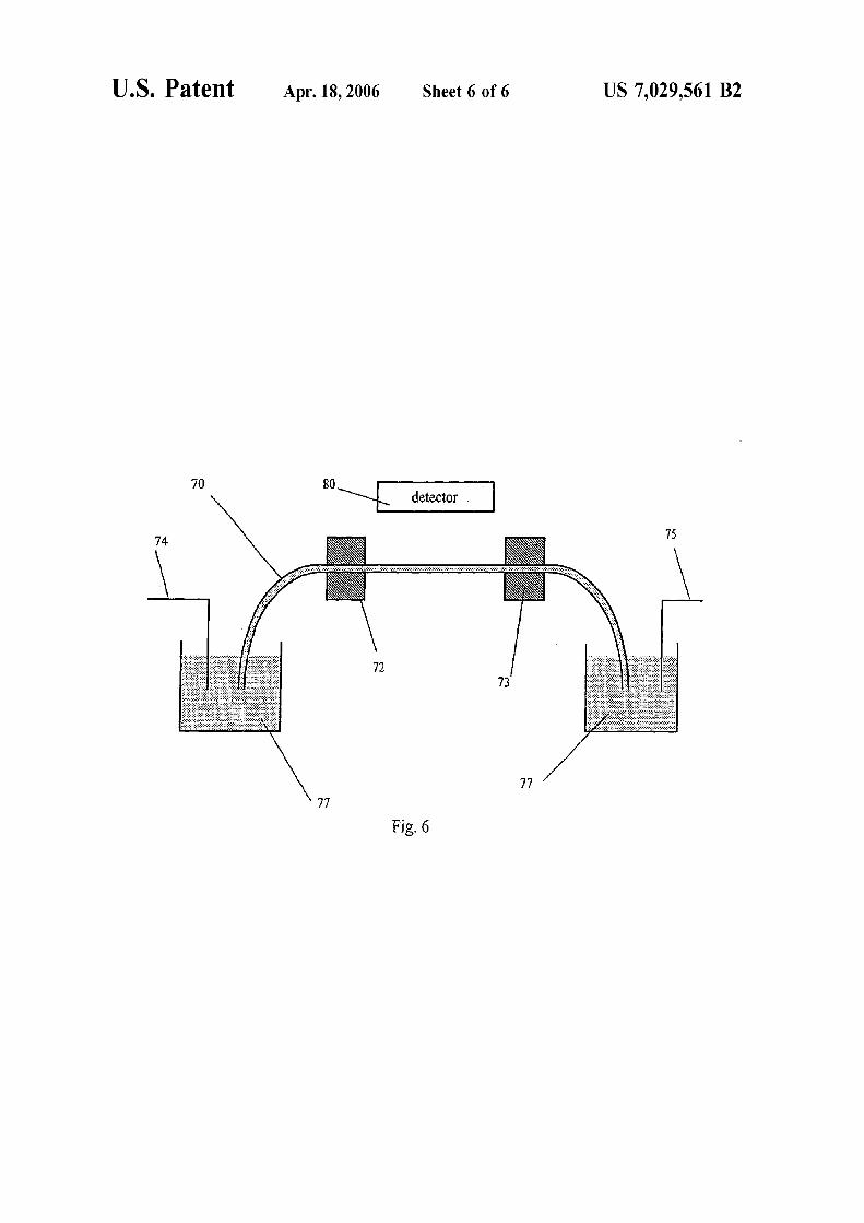
10
20
30
40
50
60
US 7029561 B2 3 4
chemical products can be avoided however only chemical species that cannot pass through the membrane or salt bridge can be focused
Two additional methods for concentrating a sample include sample stacking and field amplified sample injection in which a sample is concentrated as the sample crosses a boundary between low and high conductivity buffers These methods can achieve preconcentration factors of 100 to 1000-fold although these methods require multiple buffers Sweeping is yet another concentration method which is capable of a very high degree of sample concentration (eg up to 5000-fold) but is useful only for small hydrophoic analytes with a high affinity for a mobile micellular phase
An additional teclmique for concentrating an ionic sanlple includes isoelectric focusing Isoelectric focusing is comshy 15 monly used for the concentration and separation of proteins and involves the focusing of analytes at their respective isoelectric points (pIs) along a pH gradient
Two examples of recent isoelectric focusing techniques are provided by US Pat No 3664939 to Luner et al and US Pat No 5759370 to Pawliszyn Both references relate to isoelectric focusing with pH gradients that are created by the application of a temperature gradient The isoelectric focusing uses a pH gradient to focus analytes and in parshyticular proteins at their isoelectric points The isoelectric 25
point is the pH at which the analyte has zero electrophoretic mobility ie approximately zero charge pH gradients for isoelectric focusing are typically generated using ampholyte mixtures or illllllObilized ampholytes in gels The two above referenced patents are included here as examples of prior art uses of temperature gradients for focusing It is actually very unusual for isoelectric focusing to be done with a pH gradient generated with using a temperature gradient
One disadvantage with isoelectric focusing is that it is limited in application because it can only be used with 35
analytes with an accessible pI Additionally the concentrashytion to which a protein can be focused with isoelectric focusing is severely limited due to the low solubility of most proteins at their pIs
BRIEF SUMMARY OF THE INVENTION
The present invention concerns a method and device for concentrating and separating ionic species in solution within fluid conduits which include chmmels microchaunels and 45
capillary tubes The concentration is achieved by balancing the electrophoretic velocity of an analyte against the bulk flow of solution in the presence of a temperature gradient Using an appropriate buffer the temperature gradient can generate a corresponding gradient in the electrophoretic velocity so that the electrophoretic and bulk velocities sum to zero at a unique point and the analyte will be focused at that point The present invention may be adapted for use with any charged analyte including fluorescent dyes amino acids proteins DNA cells and particles and may provide 55
up to or in some instances exceed a 10000-fold concentrashytion of a dilute analyte
One aspect of the present invention concerns a method for directing ionic analytes contained in an ionic buffer solution of a system and which may include concentrating or sepashyrating analytes present in the buffer solution The method includes producing an electric current flow in an ionic buffer solution containing at least one species of ionic analyte to cause the analyte ions to migrate electrophoretic ally A temperature gradient is established in the buffer solution to 65
have a significant component substantially aligned with the current flow to thereby generating a gradient of the elecshy
trophoretic velocity of the analytes A bulk flow is produced in the buffer solution such that the bulk flow has a significant component substantially aligned in the direction opposite the direction of the electrophoretic migration of one or more of the analytes so that the total velocity of one or more of the analytes is equal to zero at some point in the system
According to another aspect of the present invention a fluidic device includes a fluid conduit and an ionic buffer disposed in the conduit At least one source or sink of heat thennally coupled to the fluid conduit is provided for establishing a temperature gradient having a significant component substantially aligned with the current flow so as to fonn an electrophoretic velocity gradient within the fluid conduit A voltage potential source is provided for applying an electric field along a length of the fluid conduit and a current source provides an electric current flow through the ionic buffer in the fluid conduit A source of bulk fluid flow provides for an opposing flow of the buffer in the fluid conduit In alternate further embodiments the ionic buffer has either a temperature dependent ionic strength or a temperature dependent pH such that when a temperature gradient is applied to the fluid conduit an electrophoretic velocity gradient is established in the ionic buffer present in the fluid conduit
One advantage or feature of the present invention is provided by a technique that allows for simultaneous conshycentration and separation in a mauner similar to isoelectric focusing but which is adoptable for use with any charged analyte and is not limited to molecules for a specific pI or range of pIs Further the temperature gradient focusing of the present invention can be used to achieve higher degrees of salllple concentration eg more than 10000 fold conshycentration of a dilute sample when compared with any prior single sample preconcentration method
A further feature of the present invention is that the electrophoretic velocity gradient is formed within the chanshynel or capillary in response to the temperature gradient without the need for externally manipulated voltages or complicated and difficult to fabricate semi-permeable strucshytures
Further features and advantages of the present invention will be set forth in or apparent from the detailed description of preferred embodiments thereof which follows
BRIEF DESCRIPTION OF THE DRAWINGS
The invention will now be described in detail with respect to preferred embodiments with reference to the accompashynying drawings wherein
FIG lea) is a schematic depicting a prior art micro chanshynel device which provides for electric field gradient and FIG l(b) is a plot of the electric field versus distance (x) along the microchannel of FIG lea)
FIG 2 is a plot of velocity versus distance along the microchallllel of FIG lea)
FIG 3(a) is a schematic illustration of temperature grashydient focusing and fluid conduit in the form of a micro chanshynel in accordance with the present invention FIG 3(b) depicts temperature distribution along the microchannel of FIG 3(a) and FIG 3(c) is a plot of the function
0-(20)middot ry(20) j(T) o-(T) I(T)
10
20
30
40
50
60
US 7029561 B2 5 6
plotted as a function of the distance along the microchmmel of FIG 3(a) and FIG 3(d) is a plot depicting velocity as a function of distance along the microchannel
FIG 4(a) is a schematic illustration of a microchmlllel for temperature gradient focusing created by louIe heating according to another embodiment of the present invention FIG 4(b) depicts the temperature profile along a length of the microchannel of FIG 4(a) FIG 4(c) depicts the electric field profile along a length of the microchannel of FIG 4(a) and FIG 4(d) is a plot showing electrophoretic velocity bulk velocity and total velocity vs distance along the microchanshynel of FIG 4(a)
FIG 5 is a schematic drawing of a fluidic device accordshying to fhrther embodiment of the present invention and
FIG 6 is a schematic drawing of a capillary fluidic device 15
according to an alternate embodiment of the present invenshytion
DETAILED DESCRIPTION OF THE INVENTION
The present invention provides temperature gradient focusing of a sample in a fluidic device which includes a fluid conduit such as a channel or capillary tube Temperashyture gradient focusing focuses analytes by balancing the 25 electrophoretic velocity of an analyte against the bulk velocshyity of the buffer containing the analyte If there is an appropriate gradient in the electric field the total velocity of a given charged analyte as determined by the sum of the bulk and electrophoretic velocities can be set to zero at any point along the channel and all the analyte in the system is moved toward that point However in contrast to electric field gradient focusing where the electric field gradient is applied using a combination of electrodes and membranes using temperature gradient focusing of the present invenshy 35 tion the necessary electric field gradient is produced by the application of a temperature gradient
Further description of the present invention will now be made with reference to the drawings and in particular to FIG 3(a) where a buffer-filled microchannel 10 includes electrode cOllllections 12 14 at each end The velocity of an analyte in the microchmmel 10 is given by the sum of its electrophoretic velocity UEP m1d the bulk velocity UB of the buffer
45
If there is a gradient in the electrophoretic velocity the bulk velocity can be adjusted so that the total velocity is equal to zero at a single point along the channel and the analyte will be focused at that point The electrophoretic velocity of an analyte in the microchannel 10 is given by the product of the electric field E and the electrophoretic mobility of the analyte uEP=E-flEP
A temperature gradient is applied along the length of the channel as shown in FIG 3(b) This results in corresponding 55
gradients in both the electric field E and the electrophoretic mobility ~lEP
The electric field in the microchannel 10 is given by
I E=-
AmiddotCT
where I is the electric current running through the micro- 65
channel 10 A is the channel cross-sectional area of the microchannel 10 m1d 0 is the conductivity of the buffer
Since the conductivity of the buffer is temperature-depenshydent the electric field is also temperature-dependent Here constant current is presumed because the current running through any given section of the microchmlllell 0 will be the san1e for all parts of the microchmmel whereas the voltage drop across a portion of the microchannel 10 and the electric field in the microchannel 10 will depend on the temperature of that portion One skilled in the art will readily appreciate that the present temperature gradient focusing differs from electric field gradient focusing in that in electric field gradient focusing the velocity gradient that is used for focusing results from a gradient in the electric field imposed by the addition or subtraction or current from point or points within the microchannel
Using microchannel 10 it is possible to manipulate the conductivity of the buffer by changing the temperature Consequently it is possible to produce electric field gradishyents in microfluidic devices such as microchannel 10 through the application of a temperature gradient
At fixed current density the electric field in microchmlllel 10 is inversely proportional to the conductivity of the buffer solution in the microchannel Most often the primary temshyperature dependence of the conductivity is due to the variashytion of the solvent viscosity with temperature so it can be written as a=00Y](20)(Y](T)J(T)) where 0 is the conducshytivity 00 is a constant Y](T) is the temperature dependent viscosity and f(T) is a fimction that accounts for any other temperature dependence Similarly the temperature depenshydence of the electric field is given by E=EoY] (T)J(T)Y] (20) where E is the electric field and Eo is a constant
For most buJlers the function f(T) is constm1t or only weakly dependent on temperature However it cm1 be nonshyconstant ie variable if for exmnple the ionic strength of the buffer is temperature dependent Advantageously the buffers of the present invention are characterized by a non-constant f(T)
The electrophoretic mobility of an ionic (eg analyte) species in the buffer is also dependent on the viscosity and so can be written as ~tEp=~toY](20)(Y](T)JEAT)) where flo and fEP(T) are defined in analogy to 00and f(T) where for most analytes f EP(T) will be constm1t The electrophoretic velocity of the analyte can then be written as uEP=Eofloi (T)fEAT) It should be noted that if f(T) and f EP(T) have the same temperature dependence eg they are both conshystant then UEP will not be temperature dependent m1d 311 electric field gradient produced in this way can not be used for focusing
If on the other hm1d f(T) and f EP(T) do not have the smne temperature dependence then temperature gradients will result in gradients in the electrophoretic velocity which can be used for focusing as described above
One skilled in the art will readily appreciate a major advantage of this present method over some other methods of preconcentration is that the concentration of the buffer salts is completely unaffected by the focusing This results from the fact that if the buffer salt is considered as an analyte then by definition f EAT)=f(T) and there is no gradient in the electrophoretic velocities of the buffer salts
Most c0ll1l110nly this technique would be implemented with a buffer characterized by a strongly temperature depenshydent f(T) and with analytes characterized by a constm1t or nearly constant fEP(T) However the present temperature gradient focusing can also be implemented in a system in which f(T) is constant and fEP(T) is not or in which both f(T) and fEAT) are non-constm1t but differ in their temshyperature dependence
10
20
30
40
50
60
US 7029561 B2 7 8
TIle counterbalancing bulk flow can be applied electroosshy about 500 ~ll The depth of all portions of the chailllel was motically if the electro-osmotic mobility does not differ too about 30~ The total length ofthe microchallnel was about much from the electrophoretic mobility of the analyte If the 2 cm with the length of the section 28 divided by the total electro-osmotic mobility is written as ~lEo=lEoo11(20)hl(T) length xssO8 Access to each end of the microchaunel was then by adjusting the ratio of the lengths of the hot and cold provided by a 3 nllll hole through the lid piece of the chaunels (assuming f EAT)=constant) focusing can be microchannel achieved if f(cold)lf(hot)lt-lo~LEooltf(hot)f(cold) where An 8 ~LmolL solution of carboxyfluorescein in the 18 M f(hotraquof(cold) If f(hot)ltf(cold) then the inequalities have Trisiboric buffer was prepared The analyte to be concenshythe opposite sign If x is the fraction of the total chailllel trated was the carboxyfluorescein Detection of the analyte length that is hot then focusing will occur if xJ(hot)lf was performed using a fluorescence microscope and CCD (cold)+(l-x)lt-lollEo0 ltx+(I-x)J(cold)lf(hot) where cameras Simultaneous color and grayscale images were f(hotraquof(cold) By adjusting x it is then possible to tune the obtained range of analyte mobilities that are focused To demonstrate gradient focusing using louIe heating the
It should be noted that this can also be done for micro- microcharmel was filled with the carboxyfluorescein solushychailllels of non-constant cross-section The final results are 15 tion and 1900 V was applied along its length with the essentially unchanged since in most instances the depen- positive voltage V2 applied to the narrow end via electrode dence on the cross-sectional area of the chailllel cancels out 22 and the wide end held at ground at electrode 24 in the equations As a result it is possible to generate the After 6 min the carboxyfluorescein was highly concenshytemperature gradient using louIe heating within the micro- trated at the junction between sections 26 and 28 of the chaunel This would serve to simplify the design and opera- microchannel 20 The concentration factor achieved by tion of a microfluidic device using this technique even using this example was typically about 100-fold per minute further since the focusing and the temperature gradient Referring now to FIG 5 in order to have better control of could be produced using the same pair of electrodes as the temperature gradient experiments were done using three illustrated in FIG 4(a) temperature zones two cold zones provided by cooling
Microcharmel 20 shown schematically in FIG 4(a) has 25 copper blocks 53a 53b covering much of the ends of the electrodes 22 24 and two sections sections 26 28 of microcharmel 50 and one hot zone provided by heated different cross-sectional area Section 26 has a cross-sec- copper block 52 The microchailllel50 was made out of thin tional area of 27 and section 28 has a cross-sectional area of (125 ~) sheets ofpoly( carbonate) substrate 51 which were 29 The electrical resistance per unit length of each section pressed onto the copper blocks 52 53a 53b Thermal is given by R1=1I(0A1) where 0 is the conductivity of the contact between the poly(carbonate) and the copper blocks buffer in the microcharmel 20 When a current I is passed was insured using a thermally conductive adhesive 56 The through the microcharmel 20 the power per unit length copper blocks 52 53a 53b were arranged so that there was dissipated through louIe heating in each section will be a 1 l1lln gap 58 between the heated copper block 52 and the P]=I2 middotRI=I2
(oAI ) In general the resulting temperature in cooling copper block 53a and a 2llllll gap 59 between heated section 28 will be higher than that in section 26 as shown 35 copper block 52 and the cooling copper block 53b in FIG 4(b) T2gtTI The electric field in each section of the Microchailllel 50 also includes electrodes 55 54 buffer microcharmel 20 is given by the current multiplied by the reservoirs 57 arld a narrow hot zone 50a near the middle of resistance per unit length Ei=IRi=II(oAi)=hl (Tf(T1) the microchamlel50 The heated copper block 52 was heated (00 h(20)-AJ using a small high-power resistor embedded into the copper
TIle electrophoretic velocity of arl analyte in each section and its temperature was regulated using a PID temperature of the chailllel is UEP=IloJ(T)])-I1(ooJEP(T)-A]) Ifa bulk controller (Omega Engineering Inc Stamford COilll) To flow velocity is applied along the chauneL it will not be the regulate the temperature of the cold zones 14 inch diameter sarne in each section but will instead be given by UBi=UB
0I holes were drilled through the cooling copper blocks 53a Ai where UB
0 is a constant The ratio of the electrophoretic 53b and cold water from a thermostatted bath (Neslab velocity to the bulk velocity is then given by uatio=~loJ 45 Portsmouth NH) was passed through them (TI1(ooJEP(TuBo)-uoratidegJ(T)fEE(T) via adjusting uB O Thin polycarbonate microchailllel chips ie substrate 51 so that luatidegIgtIgtluatideg1 as shown in FIG 4(d) which can was attached to the copper blocks 52 53a 53b using result in focusing Because the ratio of the electrophoretic thermally conductive adhesive 56 in the fonn of trarlsfer velocity to the bulk velocity does not depend on the cross- tape (3M) TIle substrate 51 was pressed against the copper sectional areas of the two sections the same considerations blocks 52 53a 53b from above with 3 l1lln thick PDMS as above apply if bulk flow is applied electrooslllotically (Sylgard 184 Dow Corning Midland Mich) gaskets 60 and
One preferred buffer system is composed of 09 molL a 2 l1lln thick acrylic (Acrylite OP-4 Cyro Industries Mt Trizma base and 09 molL boric acid in water (18 M Arlington NJ)) top plate 61 which was secured to the outer Trisiboric) with an expected pH of about 87 (at room copper clocks using nylon screws (not shown) temperature) From measurements of the conductivity of the 55 During temperature gradient focusing a voltage potential buffer the function f(T) was determined to vary from 1 at is applied to electrode 55 and electrode 54 is set to ground 20deg C to 077 at 70deg C to allow microcharmel50 to provide focusing and separation
louIe heating may be used to generate the temperature of different types of arlalytes small dye molecules amino gradient in the microcharmel device of FIG 4(a) The acids proteins DNA colloidal particles and cells following is a non-limiting example demonstrating louIe The microchamlel 50 may be fonned by imprinting with heating of a microchailllel of the type shown in FIG 4(a) a micro machined silicon template and then sealed with a
The microchallllel used for this demonstration was similar similar material according to the method disclosed in Ross to the one shown schematically in FIG 4(a) The width ie D Gaitan M Locascio L E Analytical Chemistry 2001 cross sectional area 29 of the narrow charmel ie section 73 4117~23 herein incorporated by reference 28 was about 70 lm and the width of the wide section ie 65 The copper block arrangement was also used to determine section 26 was of the cross sectional area 26 was about 350 the degree offocusing that could ultimately be reached with ~ The length of the tapered portion of the chamlel was temperature gradient focusing Begimung with a 8 nM
10
20
30
40
50
60
US 7029561 B2 9 10
solution of Oregon Green 488 carboxylic acid in 18 M Trislboric 100 min offocusing resulted in a focused plug of Oregon Green 488 carboxylic acid with a peak concentration over 80 ~lM~a greater than 10000-fold increase in concenshytration
It will become readily apparent to one of ordinary skill in the art that the present method provides for use innumerous applications For example temperature gradient focusing could be used as a preconcentration step before an analysis or separation or as a simultaneous concentration and sepashyration technique
In addition temperature gradient focusing may be used with any charged species in solution and not just small molecules For exanlple the analytes may include larger molecules such as proteins and DNA or even particles and 15
cells Further the present method can be used with particles to create packed beds of particles or cells for use in other analysis steps In addition the present method can be adapted for use to sort particles or cells by electrophoretic mobility
In one separation mode the bulk velocity could be ramped over time to scan focused sample peaks past a fixed detector eg the detector shown in FIG 5 This would produce results similar to capillary electrophoresis but the widths of the sample peaks would be determined by the 25
applied gradients and the peak heights would be determined by how long a given peak was in the focusing window If the ramp speed were halved the peak heights would all be doubled so that the ramp rate could be chosen dependent on the concentration limit of detection necessary Alternatively the focusing window could remain fixed and a scanning or imaging detector could be used to locate the separate peaks
In a further embodiment the method may be adapted for a system where temperature dependence is due to something other than the ionic strength An example is a system having 35
f(T) constant but fEAT) not constant or variable One way to accomplish this would be to use a buffer with a temperashyture dependent pH In such a system this embodiment of the present invention is similar to isoelectric focusing schemes However the present environment dijJers from isoelectric focusing in that in the present system an opposing buffer flow is applied so that analytes are focused at a pH other than their isoelectric points
When using any of the embodiments of the present method operating parameters which include voltage bulk 45
flow rate and temperature ofthe different zones may be held constant with time or varied with time to affect the position and width of focused sample peaks Varying of parameters may be accomplished using any of a number of methods which include the methods previously described above in which the focused sample peaks are scanned past a fixed detector
Advantageously in order to achieve the fastest accumushylation of analyte in the focused peak the highest possible voltage should be used However a higher applied voltage 55
requires a faster bulk flow which results in greater dispershysion ie wider focused peaks which is disadvantageous for separation and for achieving preconcentration of a sample to a high concentration in a very narrow peak Therefore a high voltage and fast bulk flow could be used for the initial accumulation of analyte into a relatively broad peak and the voltage flow and flow rate could be reduced to the point at which the peak is narrowest Further temperature gradients could be turned on and off to first concentrate the sample and then release the focused peak and allow it to flow on down 65
the channel Further the temperature gradient can be adjusted to be linear or nonlinear and the temperature
gradient may be monotonic or non-monotonic Thus opershyating parameters may be adjusted to achieve the desired results
While the previously disclosed embodiments are directed to a micro channel or micro fluid device the present method may be adapted for incorporation for use with substantially larger channels which may include millimeter and centimeshyter if not larger in dimension which should now be apparent to one of ordinary skill in the art Because temperature gradient focusing uses low conductivity buffers one can adapt the present method for use in much larger scale geometries than the micron-sized channels and capillaries described in detail herein
Further the previously described method can be adapted for use in modified capillary fluidic systems known to one of ordinary skill in the art FIG 6 depicts a capillary fluidic system having a capillary tube 70 spatming between two buffer reservoirs 77 Two temperature blocks denoted as heated block 72 and cooling block 73 are located along the length of the capillary tube 70 to provide a desired temperashyture gradient in the capillary tube 70 Alternatively temshyperature blocks being both cooling both heated both at ambient temperature or any combination thereof may be substituted to provide the desired temperature gradient
The buffer reservoirs 77 contain a buffer with temperature dependent ionic strength Electrodes 74 75 are connected at one end to a power supply and on the other end are in contact with the bufier solution in the buffer reservoirs 77 The power supply applies a driving voltage through the capillary tube 70 A source of bulk flow is driven either by electro-osmosis with the applied driving voltage by a presshysure gradient applied eg by a pump or a combination of the two Detector 80 is used to detect atlalytes present in the buffer solution
One of ordinary skill in the art now will readily appreciate that the present temperature gradient focusing differs from prior art methods such as sample stacking and isotashychophoresis In both cases satnples are focused or concenshytrated as a result of gradients in their electrophoretic velocishyties In sample stacking and isotachophoresis the velocity gradients are generated at the interfaces between bufiers of different composition and the point at which the concenshytration or focusing occurs is not stationary but moves along with the electroosmotic flow in the chatmel or capillary In contrast to both sample stacking and isotachophoresis the velocity gradients that produce analyte focusing in the present temperature gradient focusing result from applied temperature gradients
Further one skilled in the art will recognized that the present temperature gradient focusing differs from isoelecshytric focusing techniques such as those disclosed in us Pat Nos 3664939 and 5759370 Unlike isoelectric focusing techniques in which the pH gradient is established by using a buffer system that has a temperature dependent pH the present temperature gradient focusing utilizes a buffer that has a temperature dependent ionic strength When a temshyperature gradient and a voltage are applied to a microchanshynel the ionic strength gradient of the buffer gives rise to a velocity gradient which is used for focusing As a result atl analyte present in the buffer is focused at a point where the analytes total velocity ie the sum of the electrophoretic velocity and the bulk velocity of the buffer is zero Thereshyfore in the present temperature gradient focusing the pH and the isoelectric point of the analyte are not critical
It will now be apparent to one of ordinary skill in the art that the present microfluidic device and temperature gradient focusing method provide numerous adVatltages over prior
US 702911
devices and methods The present device and method are simpler to implement as no imbedded electrodes or salt bridges are necessary In addition like isoelectric focusing temperature gradient focusing can be used to both concenshytrate and separate analytes but without the disadvantages associated with isoelectric focusing
A fiJrther advantage of the present invention is provided in that only a single continuous buffer system is required Solid phase extraction and related preconcentrationmethods of the prior art require multiple buffers where one buffer is 10
used to carry the analyte to the preconcentrator and a second buffer is used to release the analyte from the preconcentrator Further examples of multiple buffer systems include sample stacking field amplified injection iosotachophoresis and sweeping 15
Further the present temperature gradient focusing proshyvides enlIanced concentration when compared with the prior art of other single preconcentration methods
Although the invention has been described above in relation to preferred embodiments thereof it will be undershy 20 stood by those skilled in the art that variations and modifishycations can be effected in these preferred embodiments without departing from the scope and spirit of the invention
What is claimed is 1 A method for directing ionic analytes contained in an 25
ionic buffer solution said ionic buffer solution having a temperature dependent property selected from the group consisting of ionic strength and pH said method comprising the steps of
applying an electric field to an ionic buffer solution 30
containing at least one species of ionic analyte to cause the analyte ions to have electrophoretic motion
establishing in said buffer solution a temperature gradishyent having a significant component substantially aligned with the electrophoretic motion of the analyte 35
ions which produces a gradient in the ionic strength or pH of said buffer solution thereby generating a gradishyent of the electrophoretic velocity of the aualytes and
producing a bulk flow of said buffer solution to have a significant component substantially aligned in the 40
direction opposite the direction of the electrophoretic motion of one or more of the analytes so that at least one of said one or more analytes will accmnulate or be focused at at least one point along said temperature gradient the pH at said at least one point being unequal 45
to the isoelectric point of said at least one of said one or more analytes that are focused at said at least one point
2 The method of claim 1 wherein said temperature dependent property is ionic strength and said temperature 50
gradient establishes a gradient in the ionic strength of said ionic buffer solution
3 The method of claim 2 wherein said temperature gradient is applied so as to produce an electrophoretic velocity gradient which concentrates analytes present in the 55
ionic buffer solution 4 The method of claim 2 wherein said temperature
gradient is applied so as to produce gradients in the elecshytrophoretic velocities of the analytes present in the ionic buffer solution thereby causing different analytes to focus at 60
different points within the ionic buffer solution so as to separate the different analytes
5 The method of claim 2 wherein the analyte is selected from the group consisting of small ions amino acids DNA particles cells and proteins 65
6 The method of claim 2 wherein the bulk flow is generated by electroosmosis
561 B2 12
7 The method of claim 2 wherein the bulk flow is generated by pressure gradients
8 The method of claim 2 wherein the bulk flow is generated by a combination of electroosmosis and pressure gradients
9 The method ofclaim 2 wherein at least one operational parameter selected from the group consisting of temperashyure electric field and bulk flow rate is varied over time to affect the position and width of focused sample peaks
10 The method of claim 2 wherein operational paramshyeters consisting of temperature electric field and bulk flow ate are held constant
11 The method of claim 2 wherein the temperature gradient is one of linear and non-linear
12 The method of claim 2 wherein the temperature gradient is one of monotonic and non-monotonic
13 The method of claim 2 wherein the step of establishshying a temperature gradient comprises applying an electric current to the ionic buffer solution to produce the tempera-ure gradient by Joule heating
14 The method of claim 2 wherein the ionic buffer solution is supplied as a continuous single buffer flow
15 The method of claim 2 wherein the ionic buffer solution and analytes are contained within a microchatmel
16 The method of claim 15 wherein the step of estabshylishing a temperature gradient comprises supplying thermal energy to the microchamlel via a heated block
17 The method of claim 15 wherein the step of applyinga temperature gradient comprises cooling a portion of the
icrocharmel using the ambient temperature as a maximum emperature
18 The method of claim 15 wherein the step of applyinga temperature gradient comprises supplying thennal energy o the microchanuel via a heated block and removinghermal energy from the microchanuel via a cooled block
19 The method of claim 2 wherein the ionic buffer solution and analytes are contained within a capillary tube
20 The method of claim 19 wherein the step of estabshylishing a temperature gradient comprises supplying thermal energy to the capillary tube via a heated block
21 The method of claim 19 wherein establishing aemperature gradient comprises cooling a portion of the
capillary tube using ambient temperature as a maximum emperature
22 The method of claim 19 wherein the step of estabshylishing a temperature gradient comprises supplying thermal energy to the capillary tube via a heated block and removing hermal energy from the capillary tube via a cooled block
23 The method of claim 1 wherein said temperature dependent property is pH and said temperature gradient establishes a gradient in the pH of said ionic buffer solution and whereby analytes are focused at a pH other than the isoelectric points of the respective analytes
24 The method of claim 1 wherein said temperature gradient establishes gradients in both the ionic strength and pH of the ionic buffer solution and whereby analytes are focused at a pH other than the isoelectric points of the espective analytes
25 A fluidic device comprising a fluid conduit an ionic bufier solution with a temperature dependent
property selected from the group consisting of ionic strength atId pH disposed in said fluid conduit
an electric voltage source for providing an electric field within said fluid conduit thereby causing one or more ionic analytes to have electrophoretic motion
t
r
t
mt
tt
t
t
t
r
US 7029561 B2 13
at least one heat source or heat sink thermally coupled to said fluid conduit for providing a temperature gradient having a significant component substantially aligned with the electrophoretic motion of one or more ionic analytes so as to form an electrophoretic velocity gradient within said fluid conduit and
a source of bulk fluid flow for providing flow of said ionic buffer solution in said fluid conduit in a direction opposite to the electrophoretic motion of at least one of said one or more ionic analytes 10
whereby said at least one of said one or more ionic analytes will accumulate or be focused at at least one point along said temperature gradient the pH at said at least one point being unequal to the isoelectric point of said at least one of said one or more analytes that are 15
focused at said at least one point 26 The fluid device of claim 25 wherein said temperature
dependent property is ionic strength and said temperature gradient establishes a gradient in the ionic strength of said ionic buffer solution 20
27 The fluidic device of claim 26 wherein said fluid conduit comprises a microchannel formed in a substrate having a geometry with at least one spatial dimension on the order of micrometers and where a temperature gradient is applied to said substrate 25
28 The fluidic device of claim 26 wherein said fluid conduit comprises a channel formed in a substrate and having a geometry with at least one spatial dimension on the order of at least one millimeter and where a temperature gradient is applied to said substrate 30
29 The fluidic device of claim 26 wherein said fluid conduit comprises a chamlel formed in a substrate and having a geometry with at least one spatial dimension on the
14 order of at least one centimeter and where a temperature gradient is applied to said substrate
30 The fluidic device of claim 26 wherein said at least one heat source comprises a power supply for applying an electrical current to said fluid conduit to thereby generate the temperature gradient in said ionic buffer solution by louIe heating
31 The fluidic device of claim 26 wherein said at least one heat source comprises a heated block for providing thennal energy to said fluid conduit
32 The fluidic device of claim 31 wherein said at least one heat sink further comprises a cooling block spaced from said heated block and thermally coupled to said fluid conduit for removing themlal energy from said fluid conduit
33 The fluidic device of claim 31 further comprising a thermally conductive adhesive disposed between said heated block and said fluid conduit
34 The fluidic device of claim 26 wherein said at least one heat sink comprises a cooling block for removing thermal energy from said fluid conduit
35 The fluidic device of claim 34 wherein said heat source comprises a power supply for applying an electrical current to said fluid conduit to thereby generate the temshyperature gradient in said fluid conduit
36 The fluidic device of claim 26 wherein said fluid conduit comprises a capillary tube
37 The fluid device ofclaim 25 wherein said temperature dependent property is pH and said temperature gradient establishes a gradient in the pH of said ionic bufier solution and whereby analytes are focused at a pH other than the isoelectric points of the respective analytes

10
20
30
40
50
60
US 7029561 B2 9 10
solution of Oregon Green 488 carboxylic acid in 18 M Trislboric 100 min offocusing resulted in a focused plug of Oregon Green 488 carboxylic acid with a peak concentration over 80 ~lM~a greater than 10000-fold increase in concenshytration
It will become readily apparent to one of ordinary skill in the art that the present method provides for use innumerous applications For example temperature gradient focusing could be used as a preconcentration step before an analysis or separation or as a simultaneous concentration and sepashyration technique
In addition temperature gradient focusing may be used with any charged species in solution and not just small molecules For exanlple the analytes may include larger molecules such as proteins and DNA or even particles and 15
cells Further the present method can be used with particles to create packed beds of particles or cells for use in other analysis steps In addition the present method can be adapted for use to sort particles or cells by electrophoretic mobility
In one separation mode the bulk velocity could be ramped over time to scan focused sample peaks past a fixed detector eg the detector shown in FIG 5 This would produce results similar to capillary electrophoresis but the widths of the sample peaks would be determined by the 25
applied gradients and the peak heights would be determined by how long a given peak was in the focusing window If the ramp speed were halved the peak heights would all be doubled so that the ramp rate could be chosen dependent on the concentration limit of detection necessary Alternatively the focusing window could remain fixed and a scanning or imaging detector could be used to locate the separate peaks
In a further embodiment the method may be adapted for a system where temperature dependence is due to something other than the ionic strength An example is a system having 35
f(T) constant but fEAT) not constant or variable One way to accomplish this would be to use a buffer with a temperashyture dependent pH In such a system this embodiment of the present invention is similar to isoelectric focusing schemes However the present environment dijJers from isoelectric focusing in that in the present system an opposing buffer flow is applied so that analytes are focused at a pH other than their isoelectric points
When using any of the embodiments of the present method operating parameters which include voltage bulk 45
flow rate and temperature ofthe different zones may be held constant with time or varied with time to affect the position and width of focused sample peaks Varying of parameters may be accomplished using any of a number of methods which include the methods previously described above in which the focused sample peaks are scanned past a fixed detector
Advantageously in order to achieve the fastest accumushylation of analyte in the focused peak the highest possible voltage should be used However a higher applied voltage 55
requires a faster bulk flow which results in greater dispershysion ie wider focused peaks which is disadvantageous for separation and for achieving preconcentration of a sample to a high concentration in a very narrow peak Therefore a high voltage and fast bulk flow could be used for the initial accumulation of analyte into a relatively broad peak and the voltage flow and flow rate could be reduced to the point at which the peak is narrowest Further temperature gradients could be turned on and off to first concentrate the sample and then release the focused peak and allow it to flow on down 65
the channel Further the temperature gradient can be adjusted to be linear or nonlinear and the temperature
gradient may be monotonic or non-monotonic Thus opershyating parameters may be adjusted to achieve the desired results
While the previously disclosed embodiments are directed to a micro channel or micro fluid device the present method may be adapted for incorporation for use with substantially larger channels which may include millimeter and centimeshyter if not larger in dimension which should now be apparent to one of ordinary skill in the art Because temperature gradient focusing uses low conductivity buffers one can adapt the present method for use in much larger scale geometries than the micron-sized channels and capillaries described in detail herein
Further the previously described method can be adapted for use in modified capillary fluidic systems known to one of ordinary skill in the art FIG 6 depicts a capillary fluidic system having a capillary tube 70 spatming between two buffer reservoirs 77 Two temperature blocks denoted as heated block 72 and cooling block 73 are located along the length of the capillary tube 70 to provide a desired temperashyture gradient in the capillary tube 70 Alternatively temshyperature blocks being both cooling both heated both at ambient temperature or any combination thereof may be substituted to provide the desired temperature gradient
The buffer reservoirs 77 contain a buffer with temperature dependent ionic strength Electrodes 74 75 are connected at one end to a power supply and on the other end are in contact with the bufier solution in the buffer reservoirs 77 The power supply applies a driving voltage through the capillary tube 70 A source of bulk flow is driven either by electro-osmosis with the applied driving voltage by a presshysure gradient applied eg by a pump or a combination of the two Detector 80 is used to detect atlalytes present in the buffer solution
One of ordinary skill in the art now will readily appreciate that the present temperature gradient focusing differs from prior art methods such as sample stacking and isotashychophoresis In both cases satnples are focused or concenshytrated as a result of gradients in their electrophoretic velocishyties In sample stacking and isotachophoresis the velocity gradients are generated at the interfaces between bufiers of different composition and the point at which the concenshytration or focusing occurs is not stationary but moves along with the electroosmotic flow in the chatmel or capillary In contrast to both sample stacking and isotachophoresis the velocity gradients that produce analyte focusing in the present temperature gradient focusing result from applied temperature gradients
Further one skilled in the art will recognized that the present temperature gradient focusing differs from isoelecshytric focusing techniques such as those disclosed in us Pat Nos 3664939 and 5759370 Unlike isoelectric focusing techniques in which the pH gradient is established by using a buffer system that has a temperature dependent pH the present temperature gradient focusing utilizes a buffer that has a temperature dependent ionic strength When a temshyperature gradient and a voltage are applied to a microchanshynel the ionic strength gradient of the buffer gives rise to a velocity gradient which is used for focusing As a result atl analyte present in the buffer is focused at a point where the analytes total velocity ie the sum of the electrophoretic velocity and the bulk velocity of the buffer is zero Thereshyfore in the present temperature gradient focusing the pH and the isoelectric point of the analyte are not critical
It will now be apparent to one of ordinary skill in the art that the present microfluidic device and temperature gradient focusing method provide numerous adVatltages over prior
US 702911
devices and methods The present device and method are simpler to implement as no imbedded electrodes or salt bridges are necessary In addition like isoelectric focusing temperature gradient focusing can be used to both concenshytrate and separate analytes but without the disadvantages associated with isoelectric focusing
A fiJrther advantage of the present invention is provided in that only a single continuous buffer system is required Solid phase extraction and related preconcentrationmethods of the prior art require multiple buffers where one buffer is 10
used to carry the analyte to the preconcentrator and a second buffer is used to release the analyte from the preconcentrator Further examples of multiple buffer systems include sample stacking field amplified injection iosotachophoresis and sweeping 15
Further the present temperature gradient focusing proshyvides enlIanced concentration when compared with the prior art of other single preconcentration methods
Although the invention has been described above in relation to preferred embodiments thereof it will be undershy 20 stood by those skilled in the art that variations and modifishycations can be effected in these preferred embodiments without departing from the scope and spirit of the invention
What is claimed is 1 A method for directing ionic analytes contained in an 25
ionic buffer solution said ionic buffer solution having a temperature dependent property selected from the group consisting of ionic strength and pH said method comprising the steps of
applying an electric field to an ionic buffer solution 30
containing at least one species of ionic analyte to cause the analyte ions to have electrophoretic motion
establishing in said buffer solution a temperature gradishyent having a significant component substantially aligned with the electrophoretic motion of the analyte 35
ions which produces a gradient in the ionic strength or pH of said buffer solution thereby generating a gradishyent of the electrophoretic velocity of the aualytes and
producing a bulk flow of said buffer solution to have a significant component substantially aligned in the 40
direction opposite the direction of the electrophoretic motion of one or more of the analytes so that at least one of said one or more analytes will accmnulate or be focused at at least one point along said temperature gradient the pH at said at least one point being unequal 45
to the isoelectric point of said at least one of said one or more analytes that are focused at said at least one point
2 The method of claim 1 wherein said temperature dependent property is ionic strength and said temperature 50
gradient establishes a gradient in the ionic strength of said ionic buffer solution
3 The method of claim 2 wherein said temperature gradient is applied so as to produce an electrophoretic velocity gradient which concentrates analytes present in the 55
ionic buffer solution 4 The method of claim 2 wherein said temperature
gradient is applied so as to produce gradients in the elecshytrophoretic velocities of the analytes present in the ionic buffer solution thereby causing different analytes to focus at 60
different points within the ionic buffer solution so as to separate the different analytes
5 The method of claim 2 wherein the analyte is selected from the group consisting of small ions amino acids DNA particles cells and proteins 65
6 The method of claim 2 wherein the bulk flow is generated by electroosmosis
561 B2 12
7 The method of claim 2 wherein the bulk flow is generated by pressure gradients
8 The method of claim 2 wherein the bulk flow is generated by a combination of electroosmosis and pressure gradients
9 The method ofclaim 2 wherein at least one operational parameter selected from the group consisting of temperashyure electric field and bulk flow rate is varied over time to affect the position and width of focused sample peaks
10 The method of claim 2 wherein operational paramshyeters consisting of temperature electric field and bulk flow ate are held constant
11 The method of claim 2 wherein the temperature gradient is one of linear and non-linear
12 The method of claim 2 wherein the temperature gradient is one of monotonic and non-monotonic
13 The method of claim 2 wherein the step of establishshying a temperature gradient comprises applying an electric current to the ionic buffer solution to produce the tempera-ure gradient by Joule heating
14 The method of claim 2 wherein the ionic buffer solution is supplied as a continuous single buffer flow
15 The method of claim 2 wherein the ionic buffer solution and analytes are contained within a microchatmel
16 The method of claim 15 wherein the step of estabshylishing a temperature gradient comprises supplying thermal energy to the microchamlel via a heated block
17 The method of claim 15 wherein the step of applyinga temperature gradient comprises cooling a portion of the
icrocharmel using the ambient temperature as a maximum emperature
18 The method of claim 15 wherein the step of applyinga temperature gradient comprises supplying thennal energy o the microchanuel via a heated block and removinghermal energy from the microchanuel via a cooled block
19 The method of claim 2 wherein the ionic buffer solution and analytes are contained within a capillary tube
20 The method of claim 19 wherein the step of estabshylishing a temperature gradient comprises supplying thermal energy to the capillary tube via a heated block
21 The method of claim 19 wherein establishing aemperature gradient comprises cooling a portion of the
capillary tube using ambient temperature as a maximum emperature
22 The method of claim 19 wherein the step of estabshylishing a temperature gradient comprises supplying thermal energy to the capillary tube via a heated block and removing hermal energy from the capillary tube via a cooled block
23 The method of claim 1 wherein said temperature dependent property is pH and said temperature gradient establishes a gradient in the pH of said ionic buffer solution and whereby analytes are focused at a pH other than the isoelectric points of the respective analytes
24 The method of claim 1 wherein said temperature gradient establishes gradients in both the ionic strength and pH of the ionic buffer solution and whereby analytes are focused at a pH other than the isoelectric points of the espective analytes
25 A fluidic device comprising a fluid conduit an ionic bufier solution with a temperature dependent
property selected from the group consisting of ionic strength atId pH disposed in said fluid conduit
an electric voltage source for providing an electric field within said fluid conduit thereby causing one or more ionic analytes to have electrophoretic motion
t
r
t
mt
tt
t
t
t
r
US 7029561 B2 13
at least one heat source or heat sink thermally coupled to said fluid conduit for providing a temperature gradient having a significant component substantially aligned with the electrophoretic motion of one or more ionic analytes so as to form an electrophoretic velocity gradient within said fluid conduit and
a source of bulk fluid flow for providing flow of said ionic buffer solution in said fluid conduit in a direction opposite to the electrophoretic motion of at least one of said one or more ionic analytes 10
whereby said at least one of said one or more ionic analytes will accumulate or be focused at at least one point along said temperature gradient the pH at said at least one point being unequal to the isoelectric point of said at least one of said one or more analytes that are 15
focused at said at least one point 26 The fluid device of claim 25 wherein said temperature
dependent property is ionic strength and said temperature gradient establishes a gradient in the ionic strength of said ionic buffer solution 20
27 The fluidic device of claim 26 wherein said fluid conduit comprises a microchannel formed in a substrate having a geometry with at least one spatial dimension on the order of micrometers and where a temperature gradient is applied to said substrate 25
28 The fluidic device of claim 26 wherein said fluid conduit comprises a channel formed in a substrate and having a geometry with at least one spatial dimension on the order of at least one millimeter and where a temperature gradient is applied to said substrate 30
29 The fluidic device of claim 26 wherein said fluid conduit comprises a chamlel formed in a substrate and having a geometry with at least one spatial dimension on the
14 order of at least one centimeter and where a temperature gradient is applied to said substrate
30 The fluidic device of claim 26 wherein said at least one heat source comprises a power supply for applying an electrical current to said fluid conduit to thereby generate the temperature gradient in said ionic buffer solution by louIe heating
31 The fluidic device of claim 26 wherein said at least one heat source comprises a heated block for providing thennal energy to said fluid conduit
32 The fluidic device of claim 31 wherein said at least one heat sink further comprises a cooling block spaced from said heated block and thermally coupled to said fluid conduit for removing themlal energy from said fluid conduit
33 The fluidic device of claim 31 further comprising a thermally conductive adhesive disposed between said heated block and said fluid conduit
34 The fluidic device of claim 26 wherein said at least one heat sink comprises a cooling block for removing thermal energy from said fluid conduit
35 The fluidic device of claim 34 wherein said heat source comprises a power supply for applying an electrical current to said fluid conduit to thereby generate the temshyperature gradient in said fluid conduit
36 The fluidic device of claim 26 wherein said fluid conduit comprises a capillary tube
37 The fluid device ofclaim 25 wherein said temperature dependent property is pH and said temperature gradient establishes a gradient in the pH of said ionic bufier solution and whereby analytes are focused at a pH other than the isoelectric points of the respective analytes


![(12) United States Patent US 8,346,887 B1 Kembel et a ... · (12) United States Patent Kembel et a]. US008346887B1 US 8,346,887 B1 *Jan. 1, 2013 (10) Patent N0.: (45) Date of Patent:](https://static.fdocuments.in/doc/165x107/5f51c9b29b67183a91659d37/12-united-states-patent-us-8346887-b1-kembel-et-a-12-united-states-patent.jpg)