Rosemount Wind Turbine Simulations · (1979) Human dimension and interior space: A source book of...
17
Barr Engineering Statement of Methodology Rosemount Wind Turbine Simulations
Transcript of Rosemount Wind Turbine Simulations · (1979) Human dimension and interior space: A source book of...
Barr Engineering Statement of Methodology
Rosemount Wind Turbine Simulations
TRUESCAPE CREDENTIALS
Truescape has over 12 years experience working in the 3D Photo and Video Simulation industry. Truescape has completed a wide range of different visualisation projects from Photo Simulations for simple projects to full computer generated 3D video simulations for complex projects. Truescape’s client base spans many industries, from Landscape Architecture and Engineering firms through to major New Zealand and Australian and US corporates.
Truescape adopts a team approach for project completion as each type and phase of a project calls for a different mix of specialised skill sets. This expertise spans many disciplines including photography, engineering, architecture, surveying, landscape architecture, 3D computer modelling, evidence preparation and presenting evidence as expert witnesses. All members of our staff have either formal qualifications or have undergone professional training and have direct experience working in each these specialised areas.
Truescape simulations have been produced as evidence in forums such as the New Zealand Environment and High Courts, Australia’s Victorian Civil and Administrative Tribunal and the Supreme Court. Members of Truescape’s staff have presented evidence as expert witnesses in these Courts, where our work has been subjected to cross-examination and accepted as evidence.
Truescape has assisted in providing survey controlled Photo Simulations for the following Wind Farm developments:
• 2003 – Meridian Energy, Te Apiti Farm, Council Hearing;
• 2004 – Meridian Energy, White Hill Farm, Council Hearing;
• 2004 – Southern Hydro, Dollar Wind Farm South Australia, Panel Hearing;
• 2005 – Genesis Energy, Awhitu Wind Farm, Environment Court;
• 2005 – Unison Energy, Hawkes Bay Wind Farm, Environment Court;
• 2006 – Meridian Energy, Project West Wind, Environment Court;
• 2006 – Acciona Energy, Wind Farm South Australia, Panel Hearing;
• 2007 – Invenergy, Moresville Wind Energy Park, New York; USA Permitting Hearing;
• 2008 – Bluewater Wind, Offshore Wind Farm, Maryland, USA; Permitting Hearing;
• 2008 – Bluewater Wind, Offshore Wind Farm, New Jersey, USA; Permitting Hearing
• 2008 – BP Alternative Energy – White Pines Project, Michigan, USA; Permitting
• 2008 - Meridian Energy, Project Mill Creek, Council Hearing
• 2008 – Meridian Energy, Project Hayes, Environment Court;
• 2008 – Shell Wind Energy Inc, New York State, USA; Preliminary Planning;
• 2009 – Meridian Energy, Project Central Wind, Environment Court

SCOPE OF WORK
Barr Engineering, Minneapolis engaged Truescape in Mai 2010 to:.
Provide a series of TrueView™2 “human field of view” survey controlled photo
simulations from pre-determined viewpoint locations to assist with the
assessment of the potential visibility of a proposed turbine.
Simulate two different height options for the turbine tower, being
80m vs. 100m.
VIEWPOINT LOCATIONS
The map below references the viewpoint locations photo simulations were created for:
VP 01 - Corner of Clayton Ave E and 160th St E VP 02 - Co Road 42 VP 03 - 145th St W

VALIDATION OF METHODOLOGY We have attached below some post construction analysis of the “Project West Wind”
wind farm that compared a simulation submitted built using the construction layout plan
against the completed project. This comparison of the photograph to the simulation
demonstrates the accuracy of the TrueView™ simulations.
In particular, it can be seen that the size and placement of the turbines in this simulation
is identical to the wind farm that was constructed. It should be noted that the turbines in
the simulation seem more obvious than the actual turbines in the photograph due to the
atmospheric conditions experienced on the day the photograph was taken.
The simulation and photograph were produced 2 years and 7 days apart and both are
taken at the same time of day so as to produce the same lighting and shadow
conditions.
SIMULATION OF PROJECT WEST WIND PRE CONSTRUCTION (February 2008)
PHOTOGRAPH OF PROJECT WEST WIND POST CONSTRUCTION (February 2010)
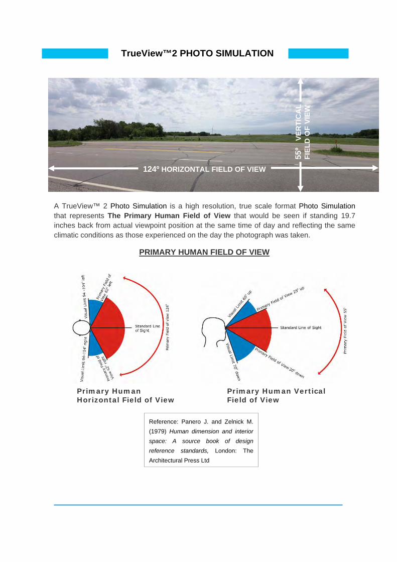
TrueView™2 PHOTO SIMULATION
55º
VER
TIC
AL
FIEL
D O
F VI
EW
124º HORIZONTAL FIELD OF VIEW
A TrueView™ 2 Photo Simulation is a high resolution, true scale format Photo Simulation that represents The Primary Human Field of View that would be seen if standing 19.7 inches back from actual viewpoint position at the same time of day and reflecting the same climatic conditions as those experienced on the day the photograph was taken.
PRIMARY HUMAN FIELD OF VIEW
Primary Human Horizontal Field of View
Primary Human Vertical Field of View
Reference: Panero J. and Zelnick M. (1979) Human dimension and interior space: A source book of design reference standards, London: The Architectural Press Ltd

TrueView™2 PHOTO SIMULATION
55º
VER
TIIC
AL
EW
FIEL
D O
F V
The TrueView™ 2 Photo Simulation when viewed at the correct height and from a distance of 19.7 inches from the centre of the image completely fills your field of view with the same view you would see at the viewpoint position.
Correct Viewing of TrueView™2 Photo Simulations
The image should be displayed level at such a height to allow the viewer’s line of sight to be directly at the centre of the image.
The viewer should be looking forward at the centre of the image at all times to ensure correct viewing as shown below.
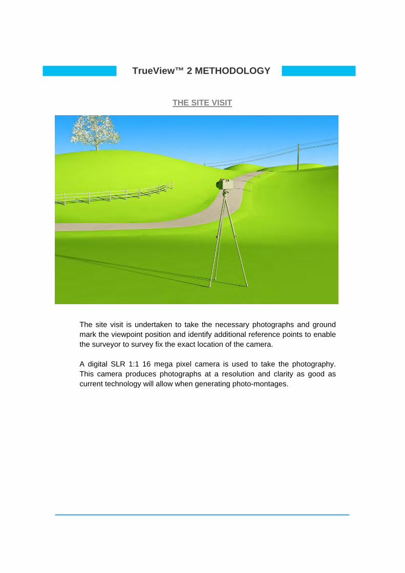
TrueView™ 2 METHODOLOGY
THE SITE VISIT
The site visit is undertaken to take the necessary photographs and ground mark the viewpoint position and identify additional reference points to enable the surveyor to survey fix the exact location of the camera.
A digital SLR 1:1 16 mega pixel camera is used to take the photography. This camera produces photographs at a resolution and clarity as good as current technology will allow when generating photo-montages.

METHODOLOGY
CREATING THE PRIMARY HUMAN FIELD OF VIEW IMAGE
erlap precisely to allow both the View to be recreated into a
single primary human field of view image.
The photographs are taken so that they ovPrimary Human Vertical and Horizontal Field of

METHODOLOGY
THE FINAL COLOUR ADJUSTED TrueView™2 PHOTOGRAPHY
55º
VER
TIC
AL
FIEL
D O
F VI
EW
Using the middle photographs as the benchmark, each of the adjoining photographs are colour adjusted to ensure consistency throughout the image. The TrueView™2 photograph is now complete.
124º HORIZONTAL FIELD OF VIEW
METHODOLOGY
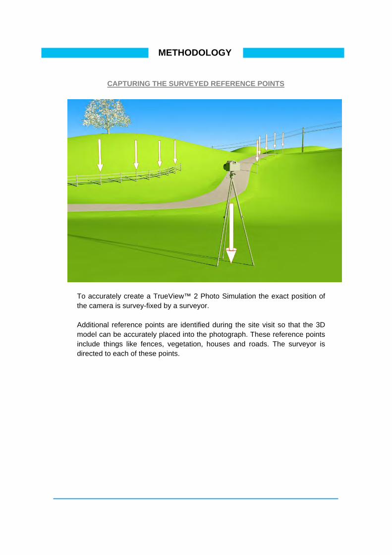
CAPTURING THE SURVEYED REFERENCE POINTS
To accurately create a TrueView™ 2 Photo Simulation the exact position of the camera is survey-fixed by a surveyor.
Additional reference points are identified during the site visit so that the 3D model can be accurately placed into the photograph. These reference points include things like fences, vegetation, houses and roads. The surveyor is directed to each of these points.
METHODOLOGY
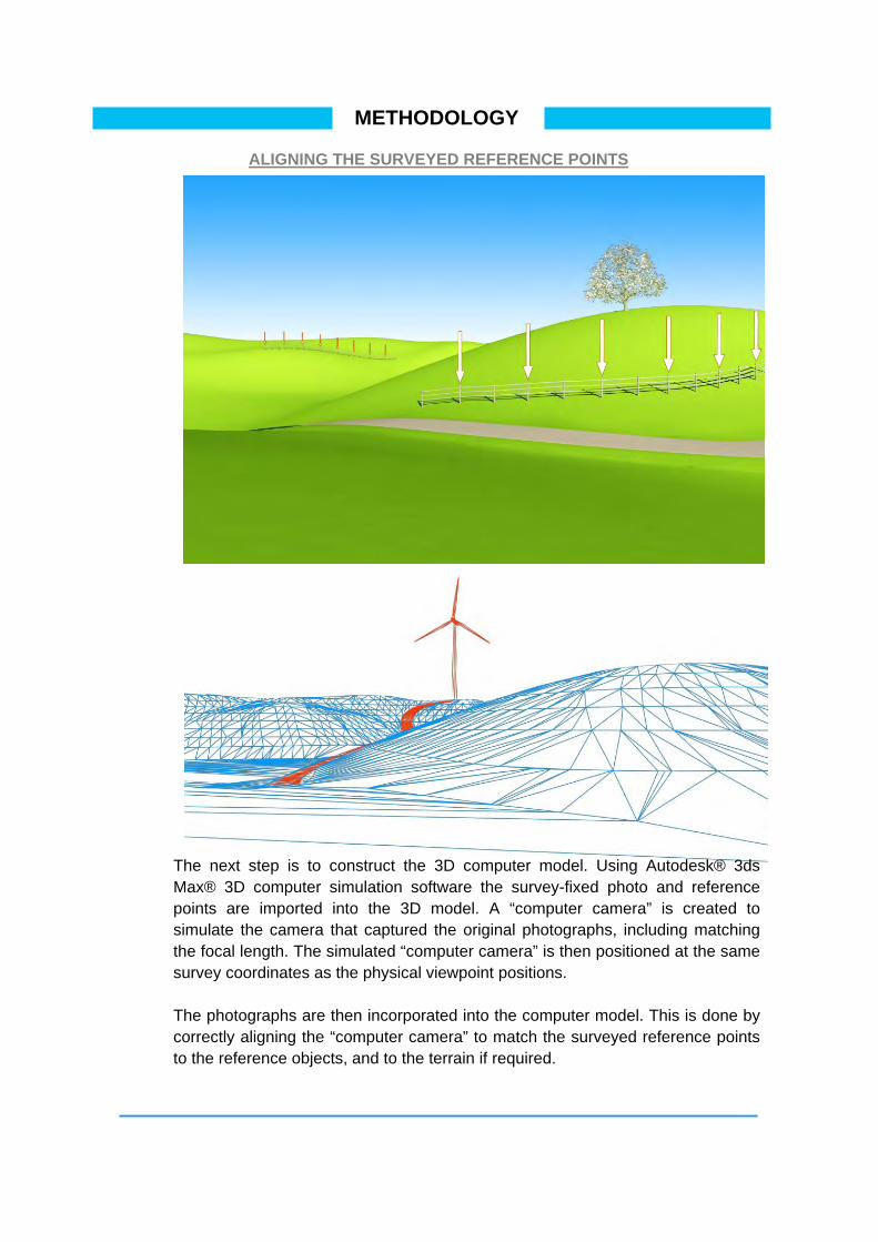
ALIGNING THE SURVEYED REFERENCE POINTS
The next step is to construct the 3D computer model. Using Autodesk® 3ds Max® 3D computer simulation software the survey-fixed photo and reference points are imported into the 3D model. A “computer camera” is created to simulate the camera that captured the original photographs, including matching the focal length. The simulated “computer camera” is then positioned at the same survey coordinates as the physical viewpoint positions.
The photographs are then incorporated into the computer model. This is done by correctly aligning the “computer camera” to match the surveyed reference points to the reference objects, and to the terrain if required.

METHODOLOGY
BUILDING THE PROPOSED PROJECT IN 3D
Option A) Clipper: Liberty 2.5 MW on Standard 80m Steel Tower
Option B) Clipper: Liberty 2.5 MW on POSTENSA 100m Concrete Tower
The proposed turbines and MET tower are then modelled in 3D in accordance with all dimensions, site layouts, colours and textures

A) Met Tower Model (130m height)
B) Met Tower Specifications

METHODOLOGY
BUILDING THE PROPOSED PROJECT IN 3D
The 3D terrain model of the site has been generated using the land contour data. The proposed development has now been modelled in 3D and is imported and positioned accurately into the scene.
The simulation software allows the sun to be simulated at the precise time the original photography was captured. This ensures the lighting of the turbines as well as the shadows they cast are an accurate depiction of how the Project would appear in the photograph at the same time of day and reflecting the same climatic conditions as those experienced at the time the photograph was taken.
METHODOLOGY
THE FINAL TrueView™2 Photo-montage
55º V
ERTI
CA
L FI
ELD
OF
VIEW
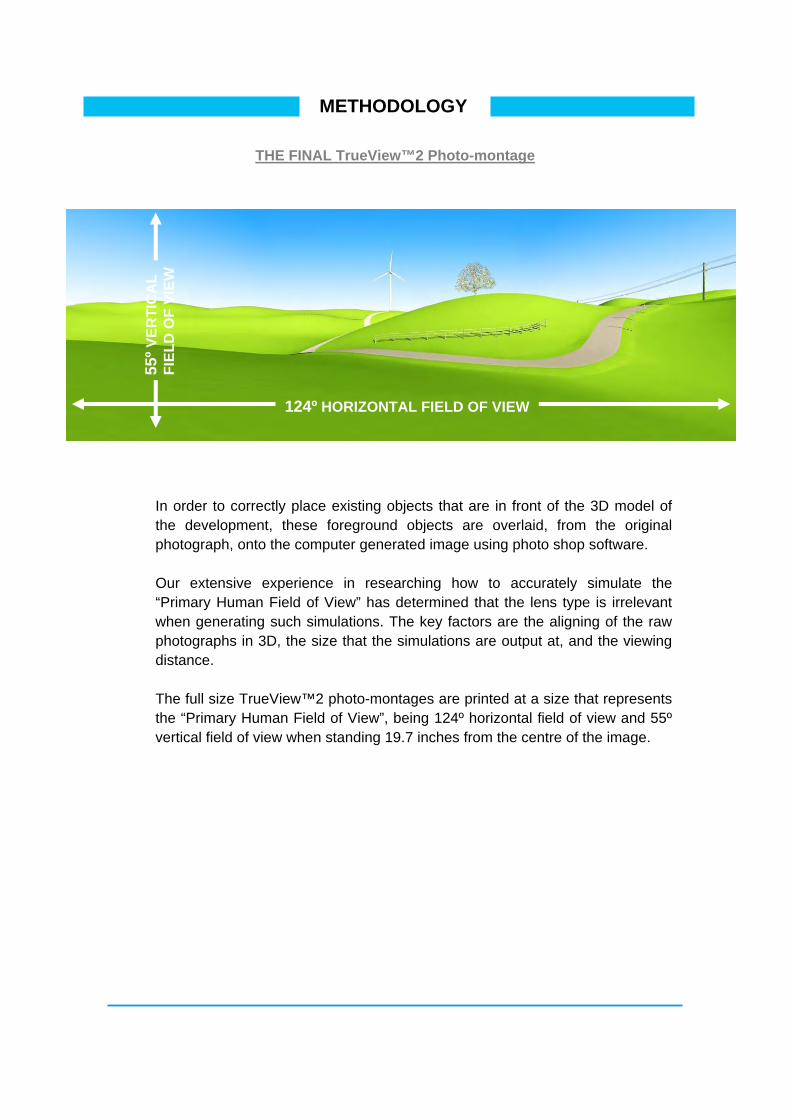
In order to correctly place existing objects that are in front of the 3D model of the development, these foreground objects are overlaid, from the original photograph, onto the computer generated image using photo shop software.
Our extensive experience in researching how to accurately simulate the “Primary Human Field of View” has determined that the lens type is irrelevant when generating such simulations. The key factors are the aligning of the raw photographs in 3D, the size that the simulations are output at, and the viewing distance.
The full size TrueView™2 photo-montages are printed at a size that represents the “Primary Human Field of View”, being 124º horizontal field of view and 55º vertical field of view when standing 19.7 inches from the centre of the image.
124º HORIZONTAL FIELD OF VIEW

SURVEY CONTROL
Using Viewpoint 02 as an example the images below represent the survey accurate alignment of reference points and terrain. All surveying was carried out by Barr Engineering, Minneapolis.
Reference points requested for survey
Reference points depicted by coloured lines have been survey fixed and used to
accurately position the wind turbine into the photograph.
The final TrueView™ 2 Photo Simulation