Rosemount 3144P Temperature 3144P Temperature Transmitter ... Calibration Trim the transmitter ......
252
Reference Manual 00809-0100-4021, Rev GC April 2014 Rosemount ® 3144P Temperature Transmitter
Transcript of Rosemount 3144P Temperature 3144P Temperature Transmitter ... Calibration Trim the transmitter ......
Reference Manual00809-0100-4021, Rev GC
April 2014
Rosemount® 3144P Temperature Transmitter

Reference Manual 00809-0100-4021, Rev GC
Title PageApril 2014
iii
Rosemount® 3144P Temperature Transmitter
NOTICE
Read this manual before working with the product. For personal and system safety, and for optimum product performance, make sure you thoroughly understand the contents before installing, using, or maintaining this product.
Within the United States, Emerson Process Management has two toll-free assistance numbers:
Customer CentralTechnical support, quoting, and order-related questions.1-800-999-9307 (7:00 am to 7:00 pm CST)
North American Response CenterEquipment service needs.1-800-654-7768 (24 hours)
International(952)-906-8888
The products described in this document are NOT designed for nuclear-qualified applications. Using non-nuclear qualified products in applications that require nuclear-qualified hardware or products may cause inaccurate readings.
For information on Rosemount nuclear-qualified products, contact your local Emerson Process Management Sales Representative.

iv
Reference Manual00809-0100-4021, Rev GC
Title PageApril 2014
v
Reference Manual 00809-0100-4021, Rev GC
Table of ContentsApril 2014
Table of Contents
1Section 1: Introduction1.1 Overview . . . . . . . . . . . . . . . . . . . . . . . . . . . . . . . . . . . . . . . . . . . . . . . . . . . . . . . . . . . . . . 1
1.1.1 Manual . . . . . . . . . . . . . . . . . . . . . . . . . . . . . . . . . . . . . . . . . . . . . . . . . . . . . . . . . . 1
1.1.2 Transmitter . . . . . . . . . . . . . . . . . . . . . . . . . . . . . . . . . . . . . . . . . . . . . . . . . . . . . . 2
1.2 Considerations . . . . . . . . . . . . . . . . . . . . . . . . . . . . . . . . . . . . . . . . . . . . . . . . . . . . . . . . . 3
1.2.1 General . . . . . . . . . . . . . . . . . . . . . . . . . . . . . . . . . . . . . . . . . . . . . . . . . . . . . . . . . . 3
1.2.2 Electrical . . . . . . . . . . . . . . . . . . . . . . . . . . . . . . . . . . . . . . . . . . . . . . . . . . . . . . . . . 3
1.2.3 Environmental . . . . . . . . . . . . . . . . . . . . . . . . . . . . . . . . . . . . . . . . . . . . . . . . . . . . 3
1.2.4 Moist or corrosive environments . . . . . . . . . . . . . . . . . . . . . . . . . . . . . . . . . . . . 4
1.2.5 Installation . . . . . . . . . . . . . . . . . . . . . . . . . . . . . . . . . . . . . . . . . . . . . . . . . . . . . . . 5
1.2.6 Software compatibility . . . . . . . . . . . . . . . . . . . . . . . . . . . . . . . . . . . . . . . . . . . . 5
1.3 Return of materials . . . . . . . . . . . . . . . . . . . . . . . . . . . . . . . . . . . . . . . . . . . . . . . . . . . . . 5
1.4 3144P revisions. . . . . . . . . . . . . . . . . . . . . . . . . . . . . . . . . . . . . . . . . . . . . . . . . . . . . . . . . 6
1.5 Confirm HART revision capability . . . . . . . . . . . . . . . . . . . . . . . . . . . . . . . . . . . . . . . . . 8
2Section 2: Installation2.1 Safety messages . . . . . . . . . . . . . . . . . . . . . . . . . . . . . . . . . . . . . . . . . . . . . . . . . . . . . . . . 9
2.2 Commissioning. . . . . . . . . . . . . . . . . . . . . . . . . . . . . . . . . . . . . . . . . . . . . . . . . . . . . . . .10
2.2.1 Setting the loop to manual . . . . . . . . . . . . . . . . . . . . . . . . . . . . . . . . . . . . . . . .10
2.2.2 Set the switches . . . . . . . . . . . . . . . . . . . . . . . . . . . . . . . . . . . . . . . . . . . . . . . . .11
2.3 Mounting . . . . . . . . . . . . . . . . . . . . . . . . . . . . . . . . . . . . . . . . . . . . . . . . . . . . . . . . . . . . .13
2.4 Installation. . . . . . . . . . . . . . . . . . . . . . . . . . . . . . . . . . . . . . . . . . . . . . . . . . . . . . . . . . . .15
2.4.1 Typical North American installation . . . . . . . . . . . . . . . . . . . . . . . . . . . . . . . .15
2.4.2 Typical European installation . . . . . . . . . . . . . . . . . . . . . . . . . . . . . . . . . . . . . .16
2.4.3 In conjunction with a Rosemount 333 HART Tri-Loop™(HART / 4–20 mA only) . . . . . . . . . . . . . . . . . . . . . . . . . . . . . . . . . . . . . . . . . . .17
2.4.4 LCD display. . . . . . . . . . . . . . . . . . . . . . . . . . . . . . . . . . . . . . . . . . . . . . . . . . . . . .18
2.4.5 Multichannel installation (HART / 4–20 mA only). . . . . . . . . . . . . . . . . . . . .20
2.5 Wiring. . . . . . . . . . . . . . . . . . . . . . . . . . . . . . . . . . . . . . . . . . . . . . . . . . . . . . . . . . . . . . . .20
2.5.1 HART / 4–20 mA . . . . . . . . . . . . . . . . . . . . . . . . . . . . . . . . . . . . . . . . . . . . . . . . .20
2.5.2 Foundation fieldbus . . . . . . . . . . . . . . . . . . . . . . . . . . . . . . . . . . . . . . . . . . . . . .23
2.5.3 Sensor connections . . . . . . . . . . . . . . . . . . . . . . . . . . . . . . . . . . . . . . . . . . . . . .23
2.6 Power supply. . . . . . . . . . . . . . . . . . . . . . . . . . . . . . . . . . . . . . . . . . . . . . . . . . . . . . . . . .24
2.6.1 Surges/transients . . . . . . . . . . . . . . . . . . . . . . . . . . . . . . . . . . . . . . . . . . . . . . . .25
2.6.2 Grounding . . . . . . . . . . . . . . . . . . . . . . . . . . . . . . . . . . . . . . . . . . . . . . . . . . . . . .25
Table of Contents

vi
Reference Manual00809-0100-4021, Rev GC
Table of ContentsApril 2014
Table of Contents
3Section 3: HART® commissioning3.1 Overview . . . . . . . . . . . . . . . . . . . . . . . . . . . . . . . . . . . . . . . . . . . . . . . . . . . . . . . . . . . . .29
3.2 Confirm HART revision capability . . . . . . . . . . . . . . . . . . . . . . . . . . . . . . . . . . . . . . . .29
3.3 Safety messages . . . . . . . . . . . . . . . . . . . . . . . . . . . . . . . . . . . . . . . . . . . . . . . . . . . . . . .30
3.4 Field communicator. . . . . . . . . . . . . . . . . . . . . . . . . . . . . . . . . . . . . . . . . . . . . . . . . . . .30
3.4.1 Updating the HART communication software . . . . . . . . . . . . . . . . . . . . . . .30
3.4.2 Device dashboard menu tree . . . . . . . . . . . . . . . . . . . . . . . . . . . . . . . . . . . . . .32
3.4.3 Device dashboard Fast Key sequences . . . . . . . . . . . . . . . . . . . . . . . . . . . . . .38
3.5 Review configuration data . . . . . . . . . . . . . . . . . . . . . . . . . . . . . . . . . . . . . . . . . . . . . .40
3.5.1 Review. . . . . . . . . . . . . . . . . . . . . . . . . . . . . . . . . . . . . . . . . . . . . . . . . . . . . . . . . .40
3.6 Check output . . . . . . . . . . . . . . . . . . . . . . . . . . . . . . . . . . . . . . . . . . . . . . . . . . . . . . . . .40
3.6.1 Analog output . . . . . . . . . . . . . . . . . . . . . . . . . . . . . . . . . . . . . . . . . . . . . . . . . . .40
3.7 Configuration . . . . . . . . . . . . . . . . . . . . . . . . . . . . . . . . . . . . . . . . . . . . . . . . . . . . . . . . .40
3.7.1 Variable mapping . . . . . . . . . . . . . . . . . . . . . . . . . . . . . . . . . . . . . . . . . . . . . . . .41
3.7.2 Sensor configuration . . . . . . . . . . . . . . . . . . . . . . . . . . . . . . . . . . . . . . . . . . . . .41
3.7.3 Change type and connections . . . . . . . . . . . . . . . . . . . . . . . . . . . . . . . . . . . . .41
3.7.4 Output units . . . . . . . . . . . . . . . . . . . . . . . . . . . . . . . . . . . . . . . . . . . . . . . . . . . .42
3.7.5 Sensor 1 serial number . . . . . . . . . . . . . . . . . . . . . . . . . . . . . . . . . . . . . . . . . . .42
3.7.6 Sensor 2 serial number . . . . . . . . . . . . . . . . . . . . . . . . . . . . . . . . . . . . . . . . . . .42
3.7.7 2-wire RTD offset . . . . . . . . . . . . . . . . . . . . . . . . . . . . . . . . . . . . . . . . . . . . . . . .42
3.7.8 Terminal (body) temperature. . . . . . . . . . . . . . . . . . . . . . . . . . . . . . . . . . . . . .43
3.7.9 Dual-sensor configuration. . . . . . . . . . . . . . . . . . . . . . . . . . . . . . . . . . . . . . . . .43
3.8 Device output configuration . . . . . . . . . . . . . . . . . . . . . . . . . . . . . . . . . . . . . . . . . . . .91
3.8.1 PV range values . . . . . . . . . . . . . . . . . . . . . . . . . . . . . . . . . . . . . . . . . . . . . . . . . .91
3.8.2 Process variable damping . . . . . . . . . . . . . . . . . . . . . . . . . . . . . . . . . . . . . . . . .92
3.8.3 Alarm and saturation . . . . . . . . . . . . . . . . . . . . . . . . . . . . . . . . . . . . . . . . . . . . .93
3.8.4 HART output . . . . . . . . . . . . . . . . . . . . . . . . . . . . . . . . . . . . . . . . . . . . . . . . . . . .94
3.8.5 LCD display options . . . . . . . . . . . . . . . . . . . . . . . . . . . . . . . . . . . . . . . . . . . . . .94
3.9 Device information . . . . . . . . . . . . . . . . . . . . . . . . . . . . . . . . . . . . . . . . . . . . . . . . . . . .94
3.9.1 Tag. . . . . . . . . . . . . . . . . . . . . . . . . . . . . . . . . . . . . . . . . . . . . . . . . . . . . . . . . . . . .94
3.9.2 Long tag . . . . . . . . . . . . . . . . . . . . . . . . . . . . . . . . . . . . . . . . . . . . . . . . . . . . . . . .94
3.9.3 Date. . . . . . . . . . . . . . . . . . . . . . . . . . . . . . . . . . . . . . . . . . . . . . . . . . . . . . . . . . . .95
3.9.4 Descriptor . . . . . . . . . . . . . . . . . . . . . . . . . . . . . . . . . . . . . . . . . . . . . . . . . . . . . .95
3.9.5 Message . . . . . . . . . . . . . . . . . . . . . . . . . . . . . . . . . . . . . . . . . . . . . . . . . . . . . . . .95
3.10Measurement filtering . . . . . . . . . . . . . . . . . . . . . . . . . . . . . . . . . . . . . . . . . . . . . . . . .95
3.10.150/60 Hz filter . . . . . . . . . . . . . . . . . . . . . . . . . . . . . . . . . . . . . . . . . . . . . . . . . . .95
3.10.2Master reset. . . . . . . . . . . . . . . . . . . . . . . . . . . . . . . . . . . . . . . . . . . . . . . . . . . . .96
vii
Reference Manual 00809-0100-4021, Rev GC
Table of ContentsApril 2014
Table of Contents
3.10.3Intermittent sensor detect . . . . . . . . . . . . . . . . . . . . . . . . . . . . . . . . . . . . . . . .96
3.10.4Intermittent threshold. . . . . . . . . . . . . . . . . . . . . . . . . . . . . . . . . . . . . . . . . . . .96
3.10.5Open sensor holdoff. . . . . . . . . . . . . . . . . . . . . . . . . . . . . . . . . . . . . . . . . . . . . .97
3.11Diagnostics and service . . . . . . . . . . . . . . . . . . . . . . . . . . . . . . . . . . . . . . . . . . . . . . . .97
3.11.1Loop test . . . . . . . . . . . . . . . . . . . . . . . . . . . . . . . . . . . . . . . . . . . . . . . . . . . . . . .98
3.12Multidrop communication. . . . . . . . . . . . . . . . . . . . . . . . . . . . . . . . . . . . . . . . . . . . . .98
3.13Use with the HART Tri-Loop. . . . . . . . . . . . . . . . . . . . . . . . . . . . . . . . . . . . . . . . . . . . .99
3.14Calibration . . . . . . . . . . . . . . . . . . . . . . . . . . . . . . . . . . . . . . . . . . . . . . . . . . . . . . . . . 121
3.14.1Calibration frequency . . . . . . . . . . . . . . . . . . . . . . . . . . . . . . . . . . . . . . . . . . 121
3.15Trim the transmitter . . . . . . . . . . . . . . . . . . . . . . . . . . . . . . . . . . . . . . . . . . . . . . . . . 122
3.15.1Sensor input trim . . . . . . . . . . . . . . . . . . . . . . . . . . . . . . . . . . . . . . . . . . . . . . 123
3.15.2Active calibrator and EMF compensation. . . . . . . . . . . . . . . . . . . . . . . . . . 124
3.15.3Transmitter-sensor matching . . . . . . . . . . . . . . . . . . . . . . . . . . . . . . . . . . . 125
3.15.4D/A output trim or scaled output trim . . . . . . . . . . . . . . . . . . . . . . . . . . . . 132
3.15.5Output trim . . . . . . . . . . . . . . . . . . . . . . . . . . . . . . . . . . . . . . . . . . . . . . . . . . . 132
3.15.6Scaled output trim . . . . . . . . . . . . . . . . . . . . . . . . . . . . . . . . . . . . . . . . . . . . . 133
3.16Troubleshooting . . . . . . . . . . . . . . . . . . . . . . . . . . . . . . . . . . . . . . . . . . . . . . . . . . . . 133
3.16.1Overview . . . . . . . . . . . . . . . . . . . . . . . . . . . . . . . . . . . . . . . . . . . . . . . . . . . . . 133
3.16.2LCD display . . . . . . . . . . . . . . . . . . . . . . . . . . . . . . . . . . . . . . . . . . . . . . . . . . . 137
3.16.3Spare parts. . . . . . . . . . . . . . . . . . . . . . . . . . . . . . . . . . . . . . . . . . . . . . . . . . . . 138
4Section 4: Foundation™ fieldbus configuration4.1 Overview . . . . . . . . . . . . . . . . . . . . . . . . . . . . . . . . . . . . . . . . . . . . . . . . . . . . . . . . . . . 139
4.2 Safety messages . . . . . . . . . . . . . . . . . . . . . . . . . . . . . . . . . . . . . . . . . . . . . . . . . . . . . 139
4.3 General block information . . . . . . . . . . . . . . . . . . . . . . . . . . . . . . . . . . . . . . . . . . . . 140
4.3.1 Device description . . . . . . . . . . . . . . . . . . . . . . . . . . . . . . . . . . . . . . . . . . . . . 140
4.3.2 Node address. . . . . . . . . . . . . . . . . . . . . . . . . . . . . . . . . . . . . . . . . . . . . . . . . . 140
4.3.3 Modes . . . . . . . . . . . . . . . . . . . . . . . . . . . . . . . . . . . . . . . . . . . . . . . . . . . . . . . . 140
4.3.4 Link Active Scheduler . . . . . . . . . . . . . . . . . . . . . . . . . . . . . . . . . . . . . . . . . . . 141
4.3.5 Capabilities. . . . . . . . . . . . . . . . . . . . . . . . . . . . . . . . . . . . . . . . . . . . . . . . . . . . 142
4.4 Foundation fieldbus function blocks . . . . . . . . . . . . . . . . . . . . . . . . . . . . . . . . . . . 142
4.5 Resource block . . . . . . . . . . . . . . . . . . . . . . . . . . . . . . . . . . . . . . . . . . . . . . . . . . . . . . 144
4.5.1 Features and Features_Sel . . . . . . . . . . . . . . . . . . . . . . . . . . . . . . . . . . . . . . 144
4.5.2 PlantWeb™ alerts . . . . . . . . . . . . . . . . . . . . . . . . . . . . . . . . . . . . . . . . . . . . . . 145
4.5.3 Recommended actions for PlantWeb alerts . . . . . . . . . . . . . . . . . . . . . . . 148
4.5.4 Recommended actions for field diagnostics per NE107 . . . . . . . . . . . . . 149
4.5.5 Resource block diagnostics. . . . . . . . . . . . . . . . . . . . . . . . . . . . . . . . . . . . . . 149
4.6 Sensor transducer block . . . . . . . . . . . . . . . . . . . . . . . . . . . . . . . . . . . . . . . . . . . . . . 150
4.6.1 Sensor transducer block diagnostics. . . . . . . . . . . . . . . . . . . . . . . . . . . . . . 151

viii
Reference Manual00809-0100-4021, Rev GC
Table of ContentsApril 2014
Table of Contents
4.7 LCD display transducer block . . . . . . . . . . . . . . . . . . . . . . . . . . . . . . . . . . . . . . . . . . 152
4.7.1 Custom meter configuration . . . . . . . . . . . . . . . . . . . . . . . . . . . . . . . . . . . . 152
4.7.2 LCD display transducer block diagnostics . . . . . . . . . . . . . . . . . . . . . . . . . 153
4.8 Hot Backup™ transducer. . . . . . . . . . . . . . . . . . . . . . . . . . . . . . . . . . . . . . . . . . . . . . 154
4.9 Analog Input (AI) . . . . . . . . . . . . . . . . . . . . . . . . . . . . . . . . . . . . . . . . . . . . . . . . . . . . 155
4.9.1 Simulation . . . . . . . . . . . . . . . . . . . . . . . . . . . . . . . . . . . . . . . . . . . . . . . . . . . . 155
4.9.2 Configure the AI block . . . . . . . . . . . . . . . . . . . . . . . . . . . . . . . . . . . . . . . . . . 156
4.9.3 Filtering. . . . . . . . . . . . . . . . . . . . . . . . . . . . . . . . . . . . . . . . . . . . . . . . . . . . . . . 159
4.9.4 Process alarms. . . . . . . . . . . . . . . . . . . . . . . . . . . . . . . . . . . . . . . . . . . . . . . . . 159
4.9.5 Status . . . . . . . . . . . . . . . . . . . . . . . . . . . . . . . . . . . . . . . . . . . . . . . . . . . . . . . . 160
4.9.6 Advanced features . . . . . . . . . . . . . . . . . . . . . . . . . . . . . . . . . . . . . . . . . . . . . 160
4.9.7 Analog input diagnostics. . . . . . . . . . . . . . . . . . . . . . . . . . . . . . . . . . . . . . . . 161
4.10Operation . . . . . . . . . . . . . . . . . . . . . . . . . . . . . . . . . . . . . . . . . . . . . . . . . . . . . . . . . . 162
4.10.1Overview . . . . . . . . . . . . . . . . . . . . . . . . . . . . . . . . . . . . . . . . . . . . . . . . . . . . . 162
4.10.2Trim the transmitter . . . . . . . . . . . . . . . . . . . . . . . . . . . . . . . . . . . . . . . . . . . 162
4.10.3Advanced diagnostics . . . . . . . . . . . . . . . . . . . . . . . . . . . . . . . . . . . . . . . . . . 164
4.10.4Statistical process monitoring (SPM) . . . . . . . . . . . . . . . . . . . . . . . . . . . . . 166
4.10.5SPM configuration . . . . . . . . . . . . . . . . . . . . . . . . . . . . . . . . . . . . . . . . . . . 167
4.11Troubleshooting guides . . . . . . . . . . . . . . . . . . . . . . . . . . . . . . . . . . . . . . . . . . . . . . 168
4.11.1Foundation fieldbus . . . . . . . . . . . . . . . . . . . . . . . . . . . . . . . . . . . . . . . . . . . . 171
4.11.2LCD display . . . . . . . . . . . . . . . . . . . . . . . . . . . . . . . . . . . . . . . . . . . . . . . . . . . 172
5Section 5: Maintenance5.1 Safety messages . . . . . . . . . . . . . . . . . . . . . . . . . . . . . . . . . . . . . . . . . . . . . . . . . . . . . 175
5.2 Maintenance . . . . . . . . . . . . . . . . . . . . . . . . . . . . . . . . . . . . . . . . . . . . . . . . . . . . . . . . 176
5.2.1 Test terminal (HART / 4–20 mA only) . . . . . . . . . . . . . . . . . . . . . . . . . . . . . 176
5.2.2 Sensor checkout . . . . . . . . . . . . . . . . . . . . . . . . . . . . . . . . . . . . . . . . . . . . . . . 176
5.2.3 Electronics housing . . . . . . . . . . . . . . . . . . . . . . . . . . . . . . . . . . . . . . . . . . . . 176
5.2.4 Transmitter diagnostics logging . . . . . . . . . . . . . . . . . . . . . . . . . . . . . . . . . 177
6Section 6: Certified safety instrumented system (safety-certified)
6.1 Safety instrumented systems (SIS) certification. . . . . . . . . . . . . . . . . . . . . . . . . . 179
6.2 Rosemount® 3144P safety certified identification . . . . . . . . . . . . . . . . . . . . . . . 179
6.3 Installation. . . . . . . . . . . . . . . . . . . . . . . . . . . . . . . . . . . . . . . . . . . . . . . . . . . . . . . . . . 180
6.4 Commissioning. . . . . . . . . . . . . . . . . . . . . . . . . . . . . . . . . . . . . . . . . . . . . . . . . . . . . . 180
6.5 Configuration . . . . . . . . . . . . . . . . . . . . . . . . . . . . . . . . . . . . . . . . . . . . . . . . . . . . . . . 180

ix
Reference Manual 00809-0100-4021, Rev GC
Table of ContentsApril 2014
Table of Contents
6.6 Safety messages . . . . . . . . . . . . . . . . . . . . . . . . . . . . . . . . . . . . . . . . . . . . . . . . . . . . . 180
6.7 Certification. . . . . . . . . . . . . . . . . . . . . . . . . . . . . . . . . . . . . . . . . . . . . . . . . . . . . . . . . 181
6.8 3144P safety-certified identification . . . . . . . . . . . . . . . . . . . . . . . . . . . . . . . . . . . 181
6.9 Installation. . . . . . . . . . . . . . . . . . . . . . . . . . . . . . . . . . . . . . . . . . . . . . . . . . . . . . . . . . 181
6.10Commissioning . . . . . . . . . . . . . . . . . . . . . . . . . . . . . . . . . . . . . . . . . . . . . . . . . . . . . 181
6.11Configuration . . . . . . . . . . . . . . . . . . . . . . . . . . . . . . . . . . . . . . . . . . . . . . . . . . . . . . . 181
6.12Operation and maintenance . . . . . . . . . . . . . . . . . . . . . . . . . . . . . . . . . . . . . . . . . . 182
6.12.1Proof test . . . . . . . . . . . . . . . . . . . . . . . . . . . . . . . . . . . . . . . . . . . . . . . . . . . . . 182
6.12.2Inspection . . . . . . . . . . . . . . . . . . . . . . . . . . . . . . . . . . . . . . . . . . . . . . . . . . . . 184
6.13Specifications . . . . . . . . . . . . . . . . . . . . . . . . . . . . . . . . . . . . . . . . . . . . . . . . . . . . . . . 184
6.13.1Failure rate data . . . . . . . . . . . . . . . . . . . . . . . . . . . . . . . . . . . . . . . . . . . . . . . 184
6.13.2Product life. . . . . . . . . . . . . . . . . . . . . . . . . . . . . . . . . . . . . . . . . . . . . . . . . . . . 184
6.14Spare parts . . . . . . . . . . . . . . . . . . . . . . . . . . . . . . . . . . . . . . . . . . . . . . . . . . . . . . . . . 184
7Section 7: Prior use (PU) safety instrumented system7.1 Overview . . . . . . . . . . . . . . . . . . . . . . . . . . . . . . . . . . . . . . . . . . . . . . . . . . . . . . . . . . . 187
7.2 Safe failure fraction . . . . . . . . . . . . . . . . . . . . . . . . . . . . . . . . . . . . . . . . . . . . . . . . . . 188
7.3 Installation. . . . . . . . . . . . . . . . . . . . . . . . . . . . . . . . . . . . . . . . . . . . . . . . . . . . . . . . . . 188
7.3.1 Switches . . . . . . . . . . . . . . . . . . . . . . . . . . . . . . . . . . . . . . . . . . . . . . . . . . . . . . 188
7.3.2 Changing switch position . . . . . . . . . . . . . . . . . . . . . . . . . . . . . . . . . . . . . . . 188
7.3.3 Proof test . . . . . . . . . . . . . . . . . . . . . . . . . . . . . . . . . . . . . . . . . . . . . . . . . . . . . 190
AAppendix A: Reference dataA.1 HART® and Foundation™ fieldbus specifications . . . . . . . . . . . . . . . . . . . . . . . . 191
A.1.1 Functional specifications . . . . . . . . . . . . . . . . . . . . . . . . . . . . . . . . . . . . . . . . 191
A.1.2 Physical specifications . . . . . . . . . . . . . . . . . . . . . . . . . . . . . . . . . . . . . . . . . . 191
A.1.3 Performance specifications. . . . . . . . . . . . . . . . . . . . . . . . . . . . . . . . . . . . . . 192
A.2 HART / 4–20 mA specifications . . . . . . . . . . . . . . . . . . . . . . . . . . . . . . . . . . . . . . . . 198
A.3 Foundation fieldbus specifications . . . . . . . . . . . . . . . . . . . . . . . . . . . . . . . . . . . . . 200
A.4 Dimensional drawings. . . . . . . . . . . . . . . . . . . . . . . . . . . . . . . . . . . . . . . . . . . . . . . . 203
A.5 Ordering information . . . . . . . . . . . . . . . . . . . . . . . . . . . . . . . . . . . . . . . . . . . . . . . . 206
A.6 Spare parts list . . . . . . . . . . . . . . . . . . . . . . . . . . . . . . . . . . . . . . . . . . . . . . . . . . . . . . 211
BAppendix B: Product CertificationsB.1 Approved Manufacturing Locations . . . . . . . . . . . . . . . . . . . . . . . . . . . . . . . . . . . . 217
B.2 European Directive Information . . . . . . . . . . . . . . . . . . . . . . . . . . . . . . . . . . . . . . . 217
B.3 Ordinary Location Certification from FM Approvals . . . . . . . . . . . . . . . . . . . . . . 217

x
Reference Manual00809-0100-4021, Rev GC
Table of ContentsApril 2014
Table of Contents
Reference Manual 00809-0100-4021, Rev GC
Section 1: IntroductionApril 2014
1Introduction
Section 1 Introduction
Overview . . . . . . . . . . . . . . . . . . . . . . . . . . . . . . . . . . . . . . . . . . . . . . . . . . . . . . . . . . . . . . . . . . page 1Considerations . . . . . . . . . . . . . . . . . . . . . . . . . . . . . . . . . . . . . . . . . . . . . . . . . . . . . . . . . . . . . page 3Return of materials . . . . . . . . . . . . . . . . . . . . . . . . . . . . . . . . . . . . . . . . . . . . . . . . . . . . . . . . . . page 53144P revisions . . . . . . . . . . . . . . . . . . . . . . . . . . . . . . . . . . . . . . . . . . . . . . . . . . . . . . . . . . . . . page 6Confirm HART revision capability . . . . . . . . . . . . . . . . . . . . . . . . . . . . . . . . . . . . . . . . . . . . . page 8
1.1 Overview
1.1.1 Manual
This manual is designed to assist in the installation, operation, and maintenance of the Rosemount® 3144P.
Section 1: Introduction
Transmitter and Manual overview
Considerations
Return of material
Section 2: Installation
Mounting
Installation
Wiring
Power supply
Section 3: HART® commissioning
Field communicator
Configuration
Multidrop communication
Calibration
Trim the transmitter
Section 4: Foundation™ fieldbus configuration
Calibration
Hardware maintenance
Diagnostic messaging
Trim the transmitter

2
Reference Manual00809-0100-4021, Rev GC
Section 1: IntroductionApril 2014
Introduction
Section 5: Maintenance
Maintenance
Troubleshooting
Section 6: Certified safety instrumented system (safety-certified)
Information regarding Safety Certified transmitters
Appendix A: Reference data
Specifications
Dimensional drawings
Ordering information
Appendix B: Product Certifications
Product certifications
Installation drawings
1.1.2 Transmitter
Industry-leading temperature transmitter delivers unmatched field reliability and innovative process measurement solutions:
Superior accuracy and stability
Dual and single sensor capability with universal sensor inputs (RTD, T/C, mV, ohms)
Comprehensive sensor and process diagnostics offering
IEC 61508 safety certification
Dual-compartment housing
Large LCD display
Selectable HART Revision (5 and 7) or FOUNDATION fieldbus protocols
Improve efficiency with best-in-class product specifications and capabilities:
Reduce maintenance and improve performance with industry leading accuracy and stability
Improve measurement accuracy by 75% with Transmitter-Sensor Matching
Ensure process health with system alerts and easy to use Device Dashboards
Easily check device status and values on local LCD display with large percent range graph
Achieve high reliability and installation ease with the industry's most rugged dual compartment design
3
Reference Manual 00809-0100-4021, Rev GC
Section 1: IntroductionApril 2014
Introduction
Optimize measurement reliability with diagnostics designed for any protocol on any host system.
Thermocouple Degradation Diagnostic monitors the health of a thermocouple loop, enabling preventative maintenance
Minimum and Maximum Temperature Tracking tracks and records temperature extremes of the process sensors and the ambient environment
Sensor Drift Alert detects sensor drift and alerts the user
the Hot Backup™ feature provides temperature measurement redundancy
Refer to the following literature for a full range of compatible connection heads, sensors, and thermowells provided by Emerson® Process Management:
Temperature Sensors and Assemblies Product Data Sheet, Volume 1 (document number 00813-0100-2654)
Temperature Sensors and Assemblies Product Data Sheet, Metric (document number 00813-0200-2654)
1.2 Considerations
1.2.1 General
Electrical temperature sensors, such as resistance temperature detectors (RTDs) and thermocouples (T/Cs), produce low-level signals proportional to temperature. The 3144P transmitter converts low-level signals to HART or FOUNDATION fieldbus and then transmits the signals to the control system via two power/signal wires.
1.2.2 Electrical
Proper electrical installation is essential to prevent errors due to sensor lead resistance and electrical noise. For HART communications, the current loop must have between 250 and 1100 ohms resistance. Refer to Figure 2-11 on page 22 for sensor and current loop connections. FOUNDATION fieldbus devices must have proper termination and power conditioning for reliable operation. Shielded cables must be used for FOUNDATION fieldbus and may only be grounded in one place.
1.2.3 Environmental
Temperature effects
The transmitter will operate within specifications for ambient temperatures between –40 and 185 °F (–40 and 85 °C). Since heat from the process is transferred from the thermowell to the transmitter housing, if the expected process temperature is near or beyond specification limits, consider using additional thermowell lagging, an extension nipple, or a remote mounting configuration to isolate the transmitter from the process. Figure 1-1 details the relationship between housing temperature rise and extension length.

4
Reference Manual00809-0100-4021, Rev GC
Section 1: IntroductionApril 2014
Introduction
Figure 1-1. 3144P Transmitter Housing Temperature Rise versus Extension Length for a Test Installation
Example:
The maximum permissible housing temperature rise (T) can be calculated by subtracting the maximum ambient temperature (A) from the transmitter’s ambient temperature specification limit (S). For instance, if A = 40 °C.
T = S - A
T = 85 °C – 40 °C
T = 45 °C
For a process temperature of 540 °C (1004 °F), an extension length of 3.6 inches (91.4 mm) yields a housing temperature rise (R) of 22 °C (72 °F), providing a safety margin of 23 °C (73 °F). A 6.0 inch (152.4 mm) extension length [R = 10 °C (50 °F)] offers a higher safety margin [35 °C (95 °F)] and reduces temperature-effect errors but would probably require extra transmitter support. Gauge the requirements for individual applications along this scale. If a thermowell with lagging is used, the extension length may be reduced by the length of the lagging.
1.2.4 Moist or corrosive environments
The 3144P temperature transmitter has a highly reliable dual compartment housing designed to resist moisture and corrosion. The sealed electronics module is mounted in a compartment that is isolated from the terminal side with conduit entries. O-ring seals protect the interior when the covers are properly installed. In humid environments, however, it is possible for moisture to accumulate in conduit lines and drain into the housing.
NoteEach transmitter is marked with a tag indicating the approvals. Install the transmitter according to all applicable installation codes, and approval and installation drawings (see Appendix B: Product Certifications). Verify that the operating atmosphere of the transmitter is consistent with the hazardous locations certifications. Once a device labeled with multiple approval types is installed, it should not be reinstalled using any of the other labeled approval types. To ensure this, the approval label should be permanently marked to distinguish the approval type(s) used.
(1,500 °F) Temperature
Oven(1,000 °F) Temperature
Oven(482 °F) TemperatureOven
Housing TemperatureRise Above
Ambient °C (°F)
60 (108)
50 (90)
40 (72)
0
30 (54)
20 (36)
10 (18)
3 4 5 6 7 8 9 Extension Length (in.)
815 °C
250 °C
540 °C 22
3.6

5
Reference Manual 00809-0100-4021, Rev GC
Section 1: IntroductionApril 2014
Introduction
1.2.5 Installation
When choosing an installation location and position, take access to the transmitter into account.
Terminal side of electronics housing
Mount the transmitter so the terminal side is accessible, allowing adequate clearance for cover removal. Best practice is to mount the transmitter with the conduit entries in a vertical position to allow for moisture drainage.
Circuit side of electronics housing
Mount the transmitter so the circuit side is accessible, providing adequate clearance for cover removal. Additional room is required for LCD display installation. The transmitter may be mounted directly to or remotely from the sensor. Using optional mounting brackets, the transmitter may be mounted to a flat surface or a 2.0 inch (50.8 mm) diameter pipe (see “Mounting” on page 192).
1.2.6 Software compatibility
Replacement transmitters may contain revised software that is not fully compatible with the existing software. The latest device descriptors (DD) are available with new field communicators or they can be loaded into existing communicators at any Emerson Process Management Service Center or via the Easy Upgrade process. For more information on upgrading a field communicator, see Section 3. To download new device drivers, visit www.AMSSuite.com.
1.3 Return of materials
To expedite the return process in North America, call the Emerson Process Management National Response Center (800-654-7768) for assistance with any needed information or materials.
The center will ask for the following information:
Product model
Serial numbers
The last process material to which the product was exposed
The center will provide
A Return Material Authorization (RMA) number
Instructions and procedures to return goods that were exposed to hazardous substances
For other locations, contact an Emerson Process Management representative.
NoteIf a hazardous substance is identified, a Material Safety Data Sheet (MSDS), required by law to be available to people exposed to specific hazardous substances, must be included with the returned materials.
6
Reference Manual00809-0100-4021, Rev GC
Section 1: IntroductionApril 2014
Introduction
1.4 3144P revisions
HART
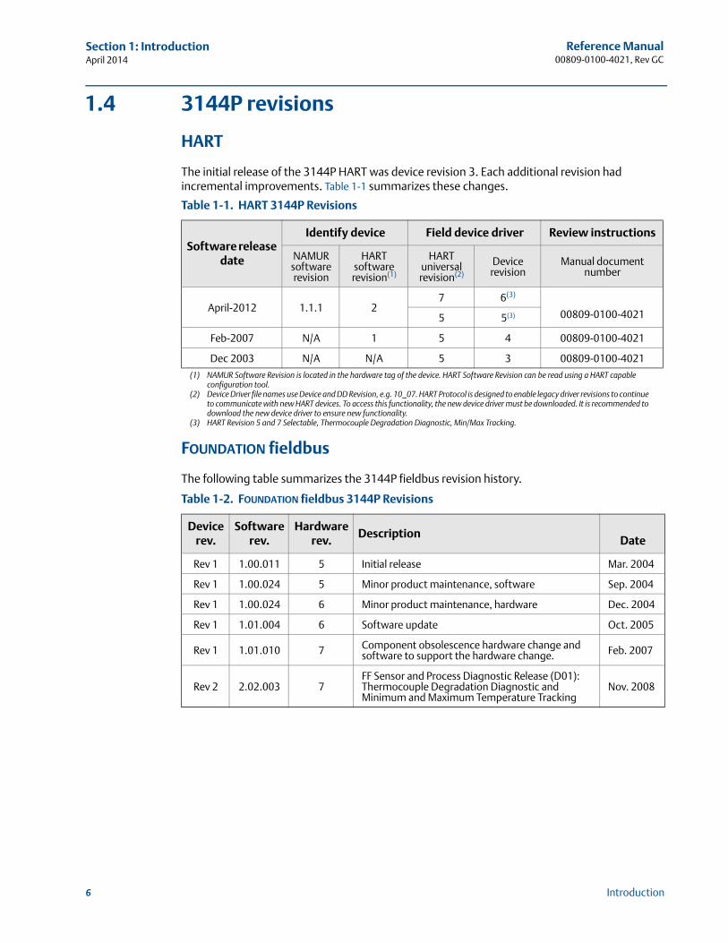
The initial release of the 3144P HART was device revision 3. Each additional revision had incremental improvements. Table 1-1 summarizes these changes.
Table 1-1. HART 3144P Revisions
Software release date
Identify device Field device driver Review instructions
NAMUR software revision
HART software revision(1)
(1) NAMUR Software Revision is located in the hardware tag of the device. HART Software Revision can be read using a HART capable configuration tool.
HART universal revision(2)
(2) Device Driver file names use Device and DD Revision, e.g. 10_07. HART Protocol is designed to enable legacy driver revisions to continue to communicate with new HART devices. To access this functionality, the new device driver must be downloaded. It is recommended to download the new device driver to ensure new functionality.
Device revision
Manual document number
April-2012 1.1.1 27 6(3)
(3) HART Revision 5 and 7 Selectable, Thermocouple Degradation Diagnostic, Min/Max Tracking.
FOUNDATION fieldbus
The following table summarizes the 3144P fieldbus revision history.
00809-0100-40215 5(3)
Feb-2007 N/A 1 5 4 00809-0100-4021
Dec 2003 N/A N/A 5 3 00809-0100-4021
Table 1-2. FOUNDATION fieldbus 3144P Revisions
Device rev.
Softwarerev.
Hardwarerev.
DescriptionDate
Rev 1 1.00.011 5 Initial release Mar. 2004
Rev 1 1.00.024 5 Minor product maintenance, software Sep. 2004
Rev 1 1.00.024 6 Minor product maintenance, hardware Dec. 2004
Rev 1 1.01.004 6 Software update Oct. 2005
Rev 1 1.01.010 7 Component obsolescence hardware change and software to support the hardware change. Feb. 2007
Rev 2 2.02.003 7FF Sensor and Process Diagnostic Release (D01): Thermocouple Degradation Diagnostic and Minimum and Maximum Temperature Tracking
Nov. 2008
7
Reference Manual 00809-0100-4021, Rev GC
Section 1: IntroductionApril 2014
Introduction
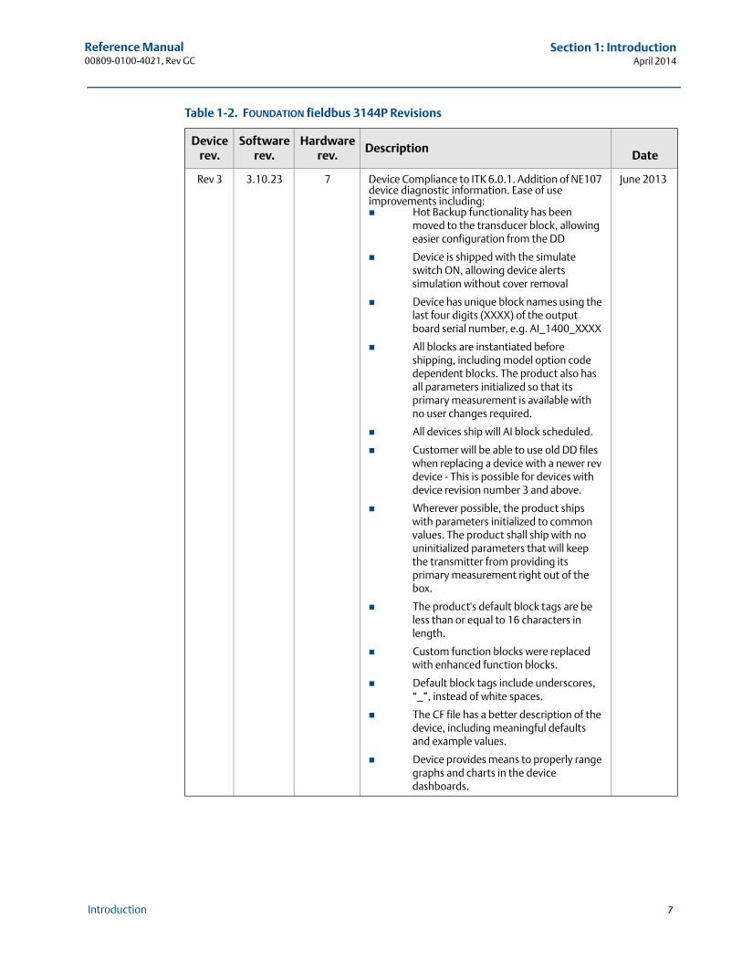
Rev 3 3.10.23 7 Device Compliance to ITK 6.0.1. Addition of NE107 device diagnostic information. Ease of use improvements including: Hot Backup functionality has been
moved to the transducer block, allowing easier configuration from the DD
Device is shipped with the simulate switch ON, allowing device alerts simulation without cover removal
Device has unique block names using the last four digits (XXXX) of the output board serial number, e.g. AI_1400_XXXX
All blocks are instantiated before shipping, including model option code dependent blocks. The product also has all parameters initialized so that its primary measurement is available with no user changes required.
All devices ship will AI block scheduled.
Customer will be able to use old DD files when replacing a device with a newer rev device - This is possible for devices with device revision number 3 and above.
Wherever possible, the product ships with parameters initialized to common values. The product shall ship with no uninitialized parameters that will keep the transmitter from providing its primary measurement right out of the box.
The product's default block tags are be less than or equal to 16 characters in length.
Custom function blocks were replaced with enhanced function blocks.
Default block tags include underscores, “_”, instead of white spaces.
The CF file has a better description of the device, including meaningful defaults and example values.
Device provides means to properly range graphs and charts in the device dashboards.
June 2013
Table 1-2. FOUNDATION fieldbus 3144P Revisions
Device rev.
Softwarerev.
Hardwarerev.
DescriptionDate
8
Reference Manual00809-0100-4021, Rev GC
Section 1: IntroductionApril 2014
Introduction
1.5 Confirm HART revision capabilityIf using HART based control or asset management systems, confirm the HART capability of those systems prior to transmitter installation. Not all systems are capable of communicating with HART Revision 7 protocol. This transmitter can be configured for either HART Revision 5 or Revision 7.
Switch HART revision mode
If the HART configuration tool is not capable of communicating with HART Revision 7, the 3144P will load a Generic Menu with limited capability. The following procedures will switch the HART revision mode from the Generic Menu.
1. Manual Setup>Device Information>Identification>Message
a. To change to HART Revision 5, Enter: “HART5” in the Message field
b. To change to HART Revision 7, Enter: “HART7” in the Message field

Reference Manual 00809-0100-4021, Rev GC
Section 2: InstallationApril 2014
9Installation
Section 2 Installation
Safety messages . . . . . . . . . . . . . . . . . . . . . . . . . . . . . . . . . . . . . . . . . . . . . . . . . . . . . . . . . . . . page 9Commissioning . . . . . . . . . . . . . . . . . . . . . . . . . . . . . . . . . . . . . . . . . . . . . . . . . . . . . . . . . . . . . page 10Mounting . . . . . . . . . . . . . . . . . . . . . . . . . . . . . . . . . . . . . . . . . . . . . . . . . . . . . . . . . . . . . . . . . . page 13Installation . . . . . . . . . . . . . . . . . . . . . . . . . . . . . . . . . . . . . . . . . . . . . . . . . . . . . . . . . . . . . . . . . page 15Wiring . . . . . . . . . . . . . . . . . . . . . . . . . . . . . . . . . . . . . . . . . . . . . . . . . . . . . . . . . . . . . . . . . . . . . page 20Power supply . . . . . . . . . . . . . . . . . . . . . . . . . . . . . . . . . . . . . . . . . . . . . . . . . . . . . . . . . . . . . . . page 24
2.1 Safety messages
Instructions and procedures in this section may require special precautions to ensure the safety of the personnel performing the operations. Information that potentially raises safety issues is indicated by a warning symbol ( ). Please refer to the following safety messages before performing an operation preceded by this symbol.
Explosions could result in death or serious injury.
Do not remove the transmitter cover in explosive atmospheres when the circuit is live. Before connecting a Field Communicator in an explosive atmosphere, make sure the
instruments in the loop are installed in accordance with intrinsically safe or non-incendive field wiring practices.
Verify that the operating atmosphere of the transmitter is consistent with the appropriate hazardous locations certifications.
Both transmitter covers must be fully engaged to meet explosion-proof requirements.Failure to follow these installation guidelines could result in death or serious injury.
Make sure only qualified personnel perform the installation.Process leaks could result in death or serious injury.
Install and tighten thermowells or sensors before applying pressure, or process leakage may result.
Do not remove the thermowell while in operation. Removing while in operation may cause process fluid leaks.
Electrical shock could cause death or serious injury. If the sensor is installed in a high-voltage environment and a fault or installation error occurs, high voltage may be present on the transmitter leads and terminals.
Use extreme caution when making contact with the leads and terminals.
10
Reference Manual00809-0100-4021, Rev GC
Section 2: InstallationApril 2014
Installation
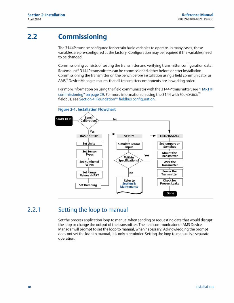
2.2 Commissioning
The 3144P must be configured for certain basic variables to operate. In many cases, these variables are pre-configured at the factory. Configuration may be required if the variables need to be changed.
Commissioning consists of testing the transmitter and verifying transmitter configuration data. Rosemount® 3144P transmitters can be commissioned either before or after installation. Commissioning the transmitter on the bench before installation using a field communicator or AMS™ Device Manager ensures that all transmitter components are in working order.
For more information on using the field communicator with the 3144P transmitter, see “HART® commissioning” on page 29. For more information on using the 3144 with FOUNDATION™ fieldbus, see Section 4: Foundation™ fieldbus configuration.
Figure 2-1. Installation Flowchart
2.2.1 Setting the loop to manual
Set the process application loop to manual when sending or requesting data that would disrupt the loop or change the output of the transmitter. The field communicator or AMS Device Manager will prompt to set the loop to manual, when necessary. Acknowledging the prompt does not set the loop to manual, it is only a reminder. Setting the loop to manual is a separate operation.
No
Yes
No
Yes
Bench Calibration?
BASIC SETUP
Refer to Section 5:
Maintenance
Set Units
Set Range Values - HART
Set Sensor Types
Set Number of Wires
VERIFY
Simulate Sensor Input
FIELD INSTALL
Set Jumpers or Switches
Mount the Transmitter
Power the Transmitter
Check for Process Leaks
Wire the Transmitter
START HERE
Done
Within Specifications?
Set Damping
11
Reference Manual 00809-0100-4021, Rev GC
Section 2: InstallationApril 2014
Installation
2.2.2 Set the switches
HART®
Without an LCD display
1. If the transmitter is installed in a loop, set the loop to manual mode and disconnect the power.
2. Remove the housing cover on the electronics side of the transmitter. Do not remove the transmitter cover in explosive atmospheres with a live circuit.
3. Set the switches to the desired position (see Figure 2-2).
4. Replace the transmitter cover. Both transmitter covers must be fully engaged to meet explosion-proof requirements.
5. Apply power and set the loop to automatic mode.
With an LCD display
1. If the transmitter is installed in a loop, set the loop to manual mode and disconnect the power.
2. Remove the housing cover on the electronics side of the transmitter. Do not remove the transmitter cover in explosive atmospheres with a live circuit.
3. Unscrew the LCD display screws and gently slide the meter straight off.
4. Set the switches to the desired position (see Figure 2-2).
5. Gently slide the LCD display back into place, taking extra precautions with the 10 pin connection.
6. Replace and tighten the LCD display screws to secure the LCD display.
7. Replace the transmitter cover. Both transmitter covers must be fully engaged to meet explosion-proof requirements.
8. Apply power and set the loop to automatic mode.
12
Reference Manual00809-0100-4021, Rev GC
Section 2: InstallationApril 2014
Installation
FOUNDATION fieldbus
Without an LCD display
1. If the transmitter is installed in a loop, set the loop to Out-of-Service (OOS) mode (if applicable) and disconnect the power.
2. Remove the housing cover on the electronics side of the transmitter. Do not remove the transmitter cover in explosive atmospheres with a live circuit.
3. Set the switches to the desired position (see Figure 2-1).
4. Replace the transmitter cover. Both transmitter covers must be fully engaged to meet explosion-proof requirements.
5. Apply power and set the loop to In-Service mode.
With an LCD display
1. If the transmitter is installed in a loop, set the loop to OOS (if applicable) and disconnect the power.
2. Remove the housing cover on the electronics side of the transmitter. Do not remove the transmitter cover in explosive atmospheres with a live circuit.
3. Unscrew the LCD display screws and gently pull the meter straight off.
4. Set the switches to the desired position.
5. Replace and tighten the LCD display screws to secure the LCD display.
6. Replace the transmitter cover. Both transmitter covers must be fully engaged to meet explosion-proof requirements.
7. Apply power and set the loop to In-Service mode.
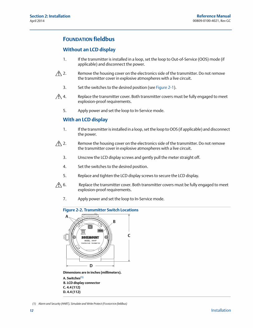
Figure 2-2. Transmitter Switch Locations
Dimensions are in inches (millimeters).
A. Switches(1)
B. LCD display connectorC. 4.4 (112)D. 4.4 (112)
(1) Alarm and Security (HART), Simulate and Write Protect (FOUNDATION fieldbus)
A
C
D
B
13
Reference Manual 00809-0100-4021, Rev GC
Section 2: InstallationApril 2014
Installation
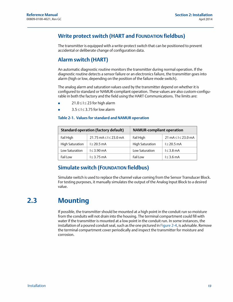
Write protect switch (HART and FOUNDATION fieldbus)
The transmitter is equipped with a write-protect switch that can be positioned to prevent accidental or deliberate change of configuration data.
Alarm switch (HART)
An automatic diagnostic routine monitors the transmitter during normal operation. If the diagnostic routine detects a sensor failure or an electronics failure, the transmitter goes into alarm (high or low, depending on the position of the failure mode switch).
The analog alarm and saturation values used by the transmitter depend on whether it is configured to standard or NAMUR-compliant operation. These values are also custom-configu-rable in both the factory and the field using the HART Communications. The limits are:
21.0 I 23 for high alarm
3.5 I 3.75 for low alarm
Table 2-1. Values for standard and NAMUR operation
Simulate switch (FOUNDATION fieldbus)
Simulate switch is used to replace the channel value coming from the Sensor Transducer Block. For testing purposes, it manually simulates the output of the Analog Input Block to a desired value.
2.3 Mounting
If possible, the transmitter should be mounted at a high point in the conduit run so moisture from the conduits will not drain into the housing. The terminal compartment could fill with water if the transmitter is mounted at a low point in the conduit run. In some instances, the installation of a poured conduit seal, such as the one pictured in Figure 2-4, is advisable. Remove the terminal compartment cover periodically and inspect the transmitter for moisture and corrosion.
Standard operation (factory default) NAMUR-compliant operation
Fail High 21.75 mA I 23.0 mA Fail High 21 mA I 23.0 mA
High Saturation I 20.5 mA High Saturation I 20.5 mA
Low Saturation I 3.90 mA Low Saturation I 3.8 mA
Fail Low I 3.75 mA Fail Low I 3.6 mA
14
Reference Manual00809-0100-4021, Rev GC
Section 2: InstallationApril 2014
Installation
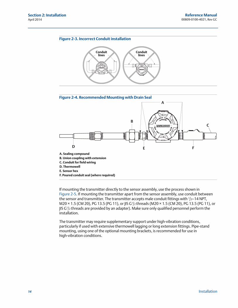
Figure 2-3. Incorrect Conduit installation
Figure 2-4. Recommended Mounting with Drain Seal
A. Sealing compoundB. Union coupling with extensionC. Conduit for field wiringD. ThermowellE. Sensor hexF. Poured conduit seal (where required)
If mounting the transmitter directly to the sensor assembly, use the process shown in Figure 2-5. If mounting the transmitter apart from the sensor assembly, use conduit between the sensor and transmitter. The transmitter accepts male conduit fittings with 1/2–14 NPT, M20 × 1.5 (CM 20), PG 13.5 (PG 11), or JIS G1/2 threads (M20 × 1.5 (CM 20), PG 13.5 (PG 11), or JIS G1/2 threads are provided by an adapter). Make sure only qualified personnel perform the installation.
The transmitter may require supplementary support under high-vibration conditions, particularly if used with extensive thermowell lagging or long extension fittings. Pipe-stand mounting, using one of the optional mounting brackets, is recommended for use in high-vibration conditions.
Conduit lines
Conduit lines
A
D
B
E F
C
15
Reference Manual 00809-0100-4021, Rev GC
Section 2: InstallationApril 2014
Installation
2.4 Installation
2.4.1 Typical North American installation
1. Attach the thermowell to the pipe or process container wall. Install and tighten thermowells and sensors, then apply process pressure to perform a leak test.
2. Attach necessary unions, couplings, and extension fittings. Seal the fitting threads with PTFE tape (if required).
3. Turn the sensor into the thermowell or directly into the process (depending on installation requirements).
4. Verify all sealing requirements for severe environments or to satisfy code requirements.
5. Attach the transmitter to the thermowell/sensor assembly. Seal all threads with PTFE tape (if required).
6. Pull sensor leads through the extensions, unions, or couplings into the terminal side of the transmitter housing.
7. Install field wiring conduit to the remaining transmitter conduit entry.
8. Pull the field wiring leads into the terminal side of the transmitter housing.
9. Attach the sensor leads to the transmitter sensor terminals. Attach the power leads to the transmitter power terminals.
10. Attach and tighten both transmitter covers since both transmitter covers must be fully engaged to meet explosion-proof requirements.
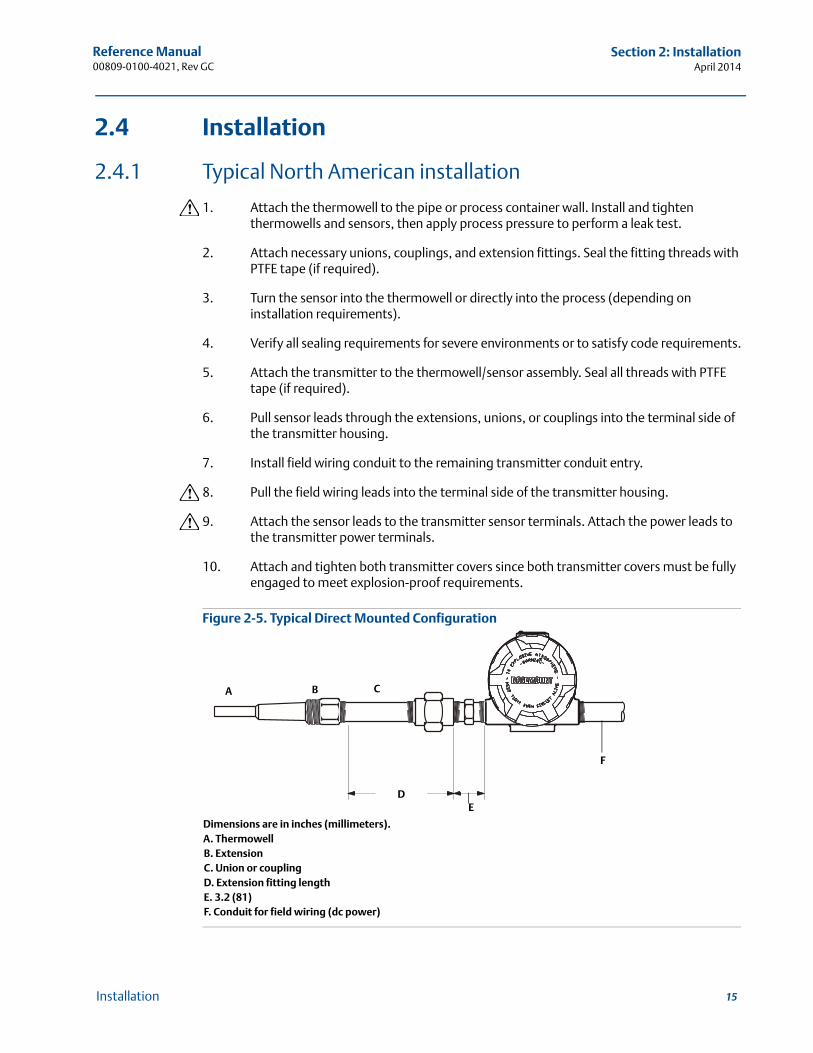
Figure 2-5. Typical Direct Mounted Configuration
Dimensions are in inches (millimeters).A. ThermowellB. ExtensionC. Union or couplingD. Extension fitting lengthE. 3.2 (81)F. Conduit for field wiring (dc power)
A B
F
ED
C
16
Reference Manual00809-0100-4021, Rev GC
Section 2: InstallationApril 2014
Installation
NoteThe National Electrical Code requires that a barrier or seal be used in addition to the primary (sensor) seal to prevent process fluid from entering the electrical conduit and continuing to the control room. Professional safety assistance is recommended for installation in potentially hazardous processes.
2.4.2 Typical European installation
1. Mount the thermowell to the pipe or the process container wall. Install and tighten thermowells and sensors then apply pressure and perform a leak check before starting the process.
2. Attach a connection head to the thermowell.
3. Insert the sensor into the thermowell and wire it to the connection head, using the wiring diagram located on the inside of the connection head.
4. Mount the transmitter to a 2-inch (50 mm) pipe or a suitable panel using one of the optional mounting brackets. The B4 bracket is shown in Figure 2-6.
5. Attach cable glands to the shielded cable running from the connection head to the transmitter conduit entry.
6. Run the shielded cable from the opposite conduit entry on the transmitter back to the control room.
7. Insert the shielded cable leads through the cable entries into the connection head and the transmitter. Connect and tighten the cable glands.
8. Connect the shielded cable leads to the connection head terminals, located inside of the connection head, and the sensor wiring terminals, located inside of the transmitter housing. Avoid contact with the leads and the terminals.
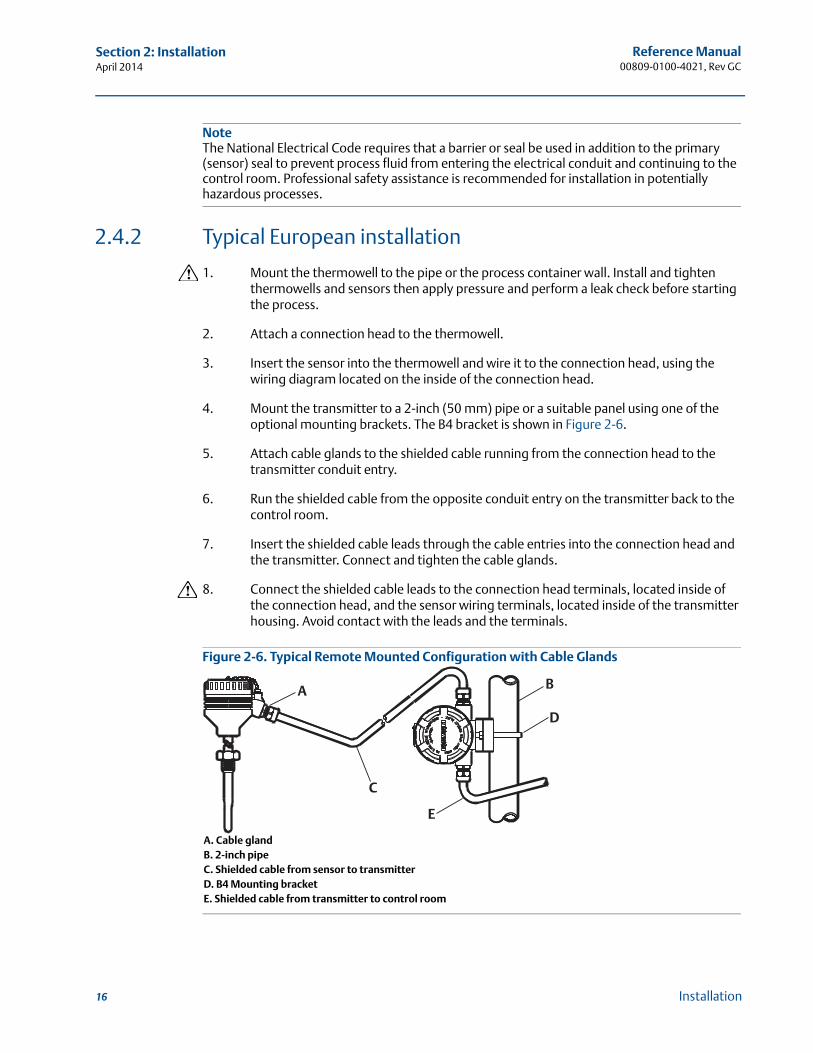
Figure 2-6. Typical Remote Mounted Configuration with Cable Glands
A. Cable glandB. 2-inch pipeC. Shielded cable from sensor to transmitterD. B4 Mounting bracketE. Shielded cable from transmitter to control room
BA
C
D
E
17
Reference Manual 00809-0100-4021, Rev GC
Section 2: InstallationApril 2014
Installation
2.4.3 In conjunction with a Rosemount 333 HART Tri-Loop™
(HART / 4–20 mA only)
Use the dual-sensor option 3144P transmitter that is operating with two sensors in conjunction with a 333 HART Tri-Loop HART-to-Analog Signal Converter to acquire an independent 4–20 mA analog output signal for each sensor input. The 3144P transmitter can be configured to output four of the six following digital process variables:
Sensor 1
Sensor 2
Differential temperature
Average temperature
First good temperature
Transmitter terminal temperature
The HART Tri-Loop reads the digital signal and outputs any or all of these variables into as many as three separate 4–20 mA analog channels.
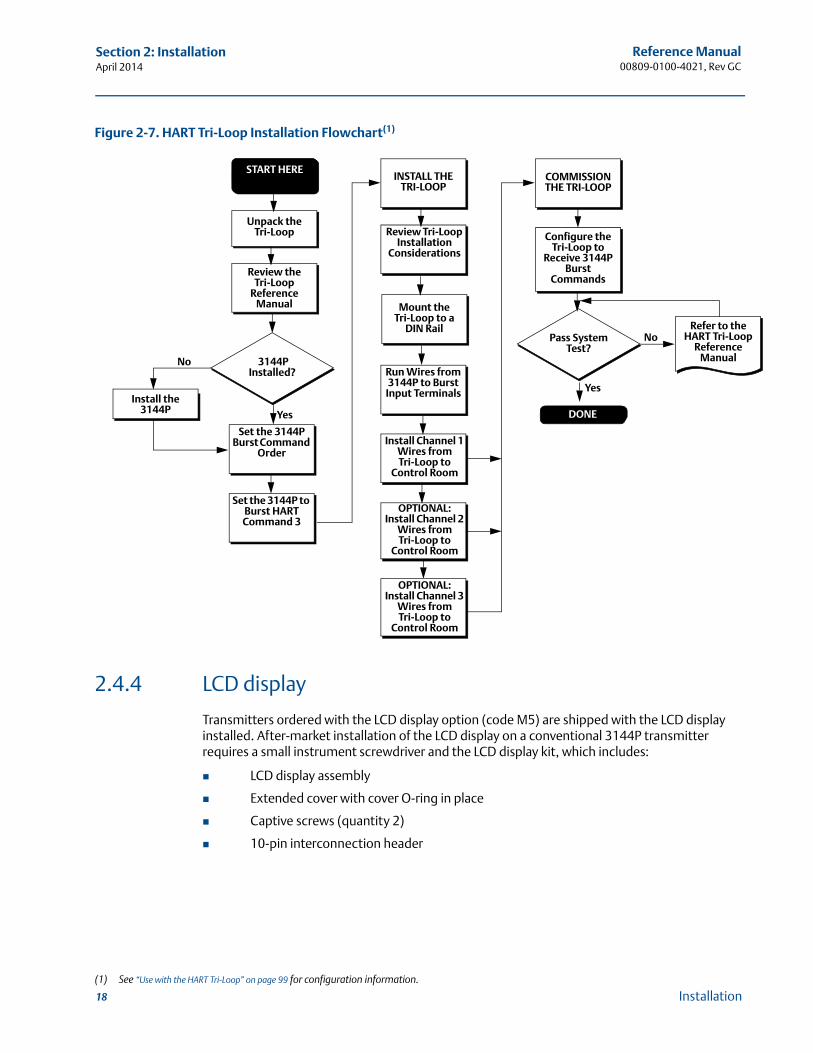
Refer to Figure 2-7 for basic installation information. Refer to the 333 HART Tri-Loop HART-to-Analog Signal Converter Reference Manual (document number 00809-0100-4754) for complete installation information.
18
Reference Manual00809-0100-4021, Rev GC
Section 2: InstallationApril 2014
Installation
Figure 2-7. HART Tri-Loop Installation Flowchart(1)
2.4.4 LCD display
Transmitters ordered with the LCD display option (code M5) are shipped with the LCD display installed. After-market installation of the LCD display on a conventional 3144P transmitter requires a small instrument screwdriver and the LCD display kit, which includes:
LCD display assembly
Extended cover with cover O-ring in place
Captive screws (quantity 2)
10-pin interconnection header
(1) See “Use with the HART Tri-Loop” on page 99 for configuration information.
START HERE
Unpack the Tri-Loop
Review the Tri-Loop
Reference Manual
Install the 3144P
Set the 3144P Burst Command
Order
Set the 3144P to Burst HART Command 3
Review Tri-Loop Installation
Considerations
Mount the Tri-Loop to a
DIN Rail
Run Wires from 3144P to Burst
Input Terminals
Install Channel 1 Wires from Tri-Loop to
Control Room
INSTALL THE TRI-LOOP
OPTIONAL: Install Channel 2
Wires from Tri-Loop to
Control Room
OPTIONAL: Install Channel 3
Wires from Tri-Loop to
Control Room
Pass System Test?
COMMISSION THE TRI-LOOP
Configure the Tri-Loop to
Receive 3144P Burst
Commands
3144P Installed?
Refer to the HART Tri-Loop
Reference Manual
DONE
No
Yes
Yes
No
19
Reference Manual 00809-0100-4021, Rev GC
Section 2: InstallationApril 2014
Installation
To install the LCD display:
1. If the transmitter is installed in a loop, set the loop to manual (HART) / out-of-service (FOUNDATION fieldbus) mode and disconnect the power.
2. Remove the housing cover from the electronics side of the transmitter. Do not remove the transmitter covers in explosive atmospheres with a live circuit.
3. Ensure that the transmitter write protect switch is set to the Off position. If transmitter security is On, the transmitter cannot be configured to recognize the LCD display. If security On is desired, configure the transmitter for the LCD display, and then install the meter.
4. Insert the interconnection header in the 10-pin socket on the face of the electronics module. Insert the pins into the electronics LCD display interface.
5. The meter can be rotated in 90-degree increments for easy viewing. Position one of the four 10-pin sockets on the back of the meter to accept the interconnection header.
6. Attach the LCD display assembly to the interconnection pins, then thread and tighten the LCD display screws into the holes on the electronics module.
7. Attach the extended cover; tighten at least one-third turn after the O-ring contacts the transmitter housing. Both transmitter covers must be fully engaged to meet explosion proof requirements.
8. Apply power and set the loop to automatic (HART) / in-service (FOUNDATION fieldbus) mode.
Once the LCD display is installed, configure the transmitter to recognize the meter option. Refer to “LCD display options” on page 94 (HART) or “LCD display transducer block” on page 152 (FOUNDATION fieldbus).
NoteObserve the following LCD display temperature limits:Operating:–4 to 185 °F (–20 to 85 °C)Storage:–50 to 185 °F (–45 to 85 °C)
20
Reference Manual00809-0100-4021, Rev GC
Section 2: InstallationApril 2014
Installation
2.4.5 Multichannel installation (HART / 4–20 mA only)
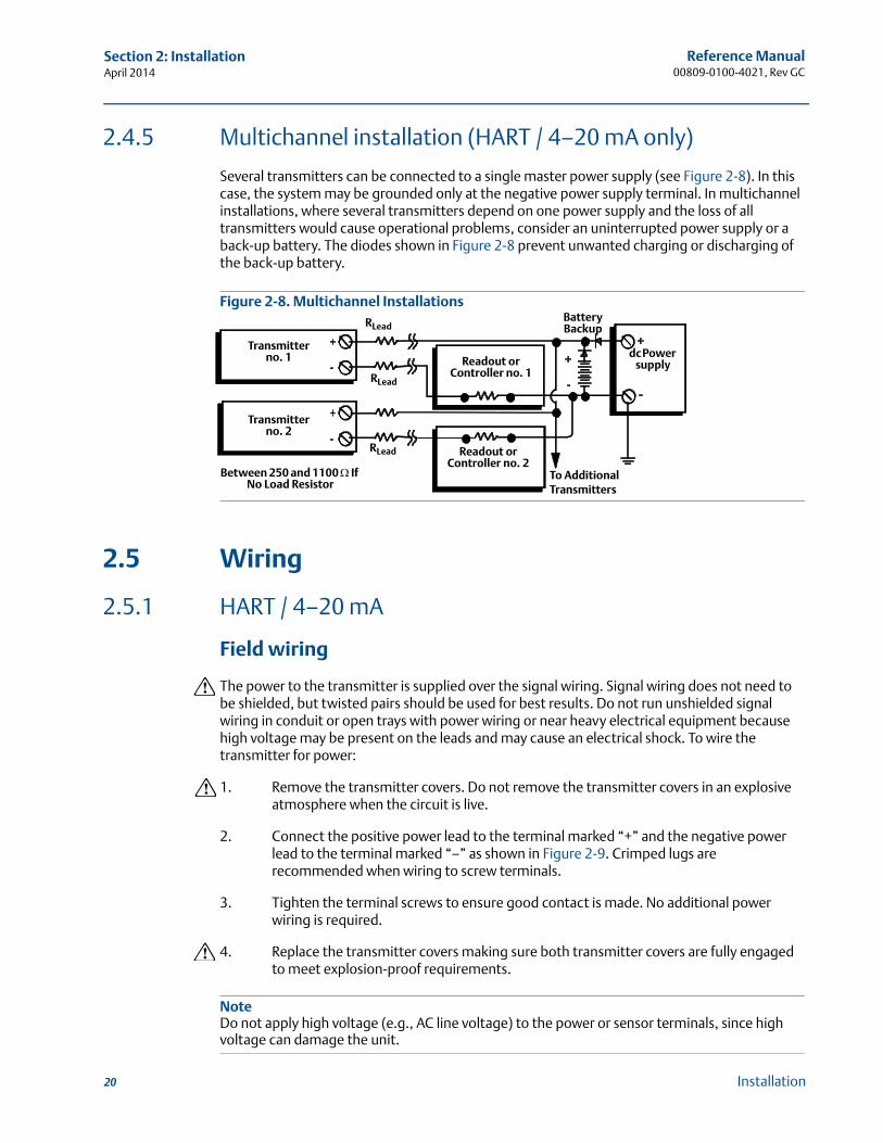
Several transmitters can be connected to a single master power supply (see Figure 2-8). In this case, the system may be grounded only at the negative power supply terminal. In multichannel installations, where several transmitters depend on one power supply and the loss of all transmitters would cause operational problems, consider an uninterrupted power supply or a back-up battery. The diodes shown in Figure 2-8 prevent unwanted charging or discharging of the back-up battery.
Figure 2-8. Multichannel Installations
2.5 Wiring
2.5.1 HART / 4–20 mA
Field wiring
The power to the transmitter is supplied over the signal wiring. Signal wiring does not need to be shielded, but twisted pairs should be used for best results. Do not run unshielded signal wiring in conduit or open trays with power wiring or near heavy electrical equipment because high voltage may be present on the leads and may cause an electrical shock. To wire the transmitter for power:
1. Remove the transmitter covers. Do not remove the transmitter covers in an explosive atmosphere when the circuit is live.
2. Connect the positive power lead to the terminal marked “+” and the negative power lead to the terminal marked “–” as shown in Figure 2-9. Crimped lugs are recommended when wiring to screw terminals.
3. Tighten the terminal screws to ensure good contact is made. No additional power wiring is required.
4. Replace the transmitter covers making sure both transmitter covers are fully engaged to meet explosion-proof requirements.
NoteDo not apply high voltage (e.g., AC line voltage) to the power or sensor terminals, since high voltage can damage the unit.
Transmitter no. 1 Readout or
Controller no. 1
Transmitter no. 2
Readout or Controller no. 2
Battery Backup
To Additional Transmitters
dc Power supply
Between 250 and 1100 If No Load Resistor
RLead
RLead
RLead

21
Reference Manual 00809-0100-4021, Rev GC
Section 2: InstallationApril 2014
Installation
Figure 2-9. Transmitter Terminal Block
A. Sensor terminals (1 – 5)B. Ground
Figure 2-10. Sensor Wiring Diagram for HART / 4–20 mA
3144P Single-sensor connections diagram
3144P dual-sensor connections diagram
(1) Transmitter must be configured for a 3-wire RTD in order to recognize an RTD with a compensation loop.(2) Emerson Process Management provides 4-wire sensors for all single-element RTDs. Use these RTDs in 2-wire or 3-wire configurations by leaving the unneeded leads
disconnected and insulated with electrical tape.
“+”
A
Test
B
“-”
“+”“-”
B
A
Wiring connections Wiring connections(with “T1” integral transient protection option)
4-wire RTD and Ohms
T/Cs and Millivolts
RTD with Compensation Loop(1)
2-wire RTD and Ohms
3-wire RTD and Ohms(2)
T/Hot Backup/Dual Sensor with
2 RTDs
T/Hot Backup/Dual Sensor with 2
Thermocouples
T/Hot Backup/Dual
Sensor with RTDs/ Thermocouples(2)
T/Hot Backup/Dual Sensor with
RTDs/ Thermocouples(2)
T/Hot Backup/DualSensor with 2 RTDs with Compensation
Loop(2)
22
Reference Manual00809-0100-4021, Rev GC
Section 2: InstallationApril 2014
Installation
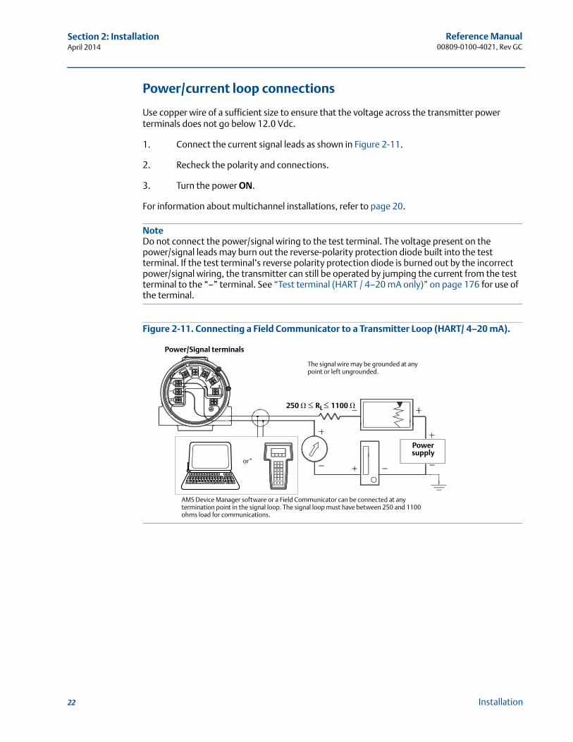
Power/current loop connections
Use copper wire of a sufficient size to ensure that the voltage across the transmitter power terminals does not go below 12.0 Vdc.
1. Connect the current signal leads as shown in Figure 2-11.
2. Recheck the polarity and connections.
3. Turn the power ON.
For information about multichannel installations, refer to page 20.
NoteDo not connect the power/signal wiring to the test terminal. The voltage present on the power/signal leads may burn out the reverse-polarity protection diode built into the test terminal. If the test terminal’s reverse polarity protection diode is burned out by the incorrect power/signal wiring, the transmitter can still be operated by jumping the current from the test terminal to the “–” terminal. See “Test terminal (HART / 4–20 mA only)” on page 176 for use of the terminal.
Figure 2-11. Connecting a Field Communicator to a Transmitter Loop (HART/ 4–20 mA).
Power/Signal terminals
The signal wire may be grounded at any point or left ungrounded.
Powersupply
250 � RL 1100 �
AMS Device Manager software or a Field Communicator can be connected at any termination point in the signal loop. The signal loop must have between 250 and 1100 ohms load for communications.
or*
23
Reference Manual 00809-0100-4021, Rev GC
Section 2: InstallationApril 2014
Installation
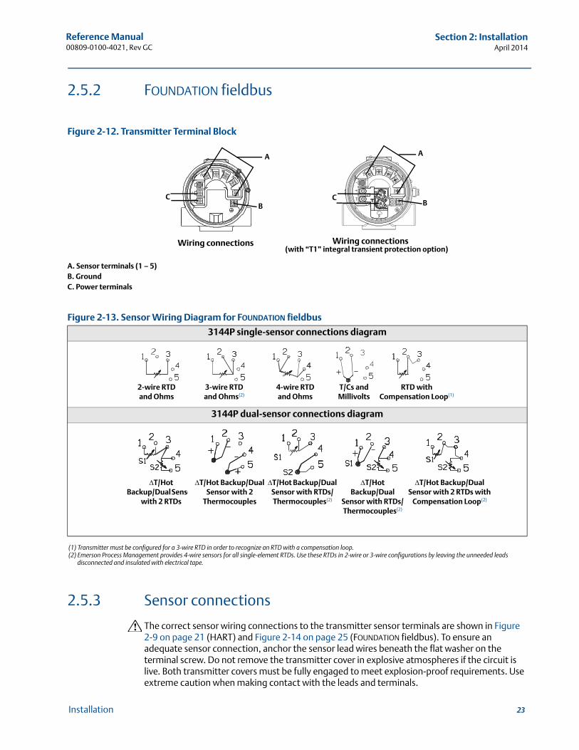
2.5.2 FOUNDATION fieldbus
Figure 2-12. Transmitter Terminal Block
A. Sensor terminals (1 – 5)B. GroundC. Power terminals
2.5.3 Sensor connections
The correct sensor wiring connections to the transmitter sensor terminals are shown in Figure 2-9 on page 21 (HART) and Figure 2-14 on page 25 (FOUNDATION fieldbus). To ensure an adequate sensor connection, anchor the sensor lead wires beneath the flat washer on the terminal screw. Do not remove the transmitter cover in explosive atmospheres if the circuit is live. Both transmitter covers must be fully engaged to meet explosion-proof requirements. Use extreme caution when making contact with the leads and terminals.
Figure 2-13. Sensor Wiring Diagram for FOUNDATION fieldbus
3144P single-sensor connections diagram
3144P dual-sensor connections diagram
(1) Transmitter must be configured for a 3-wire RTD in order to recognize an RTD with a compensation loop.(2) Emerson Process Management provides 4-wire sensors for all single-element RTDs. Use these RTDs in 2-wire or 3-wire configurations by leaving the unneeded leads
disconnected and insulated with electrical tape.
A
BC C
B
A
Wiring connections Wiring connections(with “T1” integral transient protection option)
4-wire RTD and Ohms
T/Cs and Millivolts
RTD with Compensation Loop(1)
2-wire RTD and Ohms
3-wire RTD and Ohms(2)
T/Hot Backup/Dual Sensor
with 2 RTDs
T/Hot Backup/Dual Sensor with 2
Thermocouples
T/Hot Backup/Dual
Sensor with RTDs/ Thermocouples(2)
T/Hot Backup/Dual Sensor with RTDs/ Thermocouples(2)
T/Hot Backup/DualSensor with 2 RTDs with
Compensation Loop(2)

24
Reference Manual00809-0100-4021, Rev GC
Section 2: InstallationApril 2014
Installation
RTD or ohm inputs
If the transmitter is mounted remotely from a 3- or 4-wire RTD, it will operate within specifica-tions, without recalibration, for lead wire resistances of up to 60 ohms per lead (equivalent to 1,000 feet of 20 AWG wire). In this case, the leads between the RTD and transmitter should be shielded. If using only two leads (or a compensation loop lead wire configuration), both RTD leads are in series with the sensor element, so significant errors can occur if the lead lengths exceed one foot of 20 AWG wire. For longer runs, attach a third or fourth lead as described above. To eliminate 2-wire lead resistance error, the 2-wire offset command can be used. This allows the user to input the measured lead wire resistance, resulting in the transmitter adjusting the temperature to correct the error.
Thermocouple or millivolt inputs
For direct-mount applications, connect the thermocouple directly to the transmitter. If mounting the transmitter remotely from the sensor, use appropriate thermocouple extension wire. Make connections for millivolt inputs with copper wire. Use shielding for long runs of wire.
NoteFor HART transmitters, the use of two grounded thermocouples with a dual option 3144P transmitter is not recommended. For applications in which the use of two thermocouples is desired, connect either two ungrounded thermocouples, one grounded and one ungrounded thermocouple, or one dual element thermocouple.
2.6 Power supply
HART
An external power supply is required to operate the 3144P (not included). The input voltage range of the transmitter is 12 to 42.4 Vdc. This is the power required across the transmitter power terminals. The power terminals are rated to 42.4 Vdc. With 250 ohms of resistance in the loop, the transmitter requires a minimum of 18.1 Vdc for communication.
The power supplied to the transmitter is determined by the total loop resistance and should not drop below the lift-off voltage. The lift-off voltage is the minimum supply voltage required for any given total loop resistance. See Figure 2-14 to determine the required supply voltage. If the power drops below the lift-off voltage while the transmitter is being configured, the transmitter may output incorrect information.
The dc power supply should provide power with less than 2% ripple. The total resistance load is the sum of the resistance of the signal leads and the load resistance of any controller, indicator, or related piece of equipment in the loop. Note that the resistance of intrinsic safety barriers, if used, must be included.
NotePermanent damage to the transmitter could result if the voltage drops below 12.0 Vdc at the power terminals, when changing transmitter configuration parameters.
25
Reference Manual 00809-0100-4021, Rev GC
Section 2: InstallationApril 2014
Installation
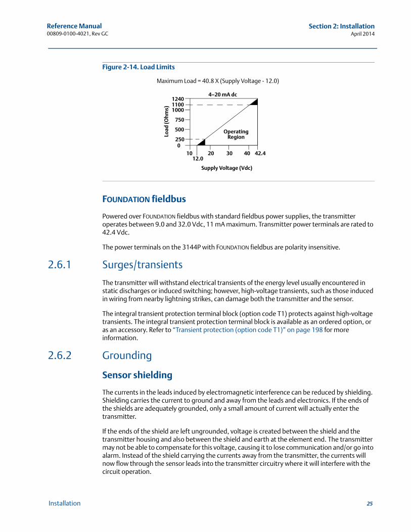
Figure 2-14. Load Limits
FOUNDATION fieldbus
Powered over FOUNDATION fieldbus with standard fieldbus power supplies, the transmitter operates between 9.0 and 32.0 Vdc, 11 mA maximum. Transmitter power terminals are rated to 42.4 Vdc.
The power terminals on the 3144P with FOUNDATION fieldbus are polarity insensitive.
2.6.1 Surges/transients
The transmitter will withstand electrical transients of the energy level usually encountered in static discharges or induced switching; however, high-voltage transients, such as those induced in wiring from nearby lightning strikes, can damage both the transmitter and the sensor.
The integral transient protection terminal block (option code T1) protects against high-voltage transients. The integral transient protection terminal block is available as an ordered option, or as an accessory. Refer to “Transient protection (option code T1)” on page 198 for more information.
2.6.2 Grounding
Sensor shielding
The currents in the leads induced by electromagnetic interference can be reduced by shielding. Shielding carries the current to ground and away from the leads and electronics. If the ends of the shields are adequately grounded, only a small amount of current will actually enter the transmitter.
If the ends of the shield are left ungrounded, voltage is created between the shield and the transmitter housing and also between the shield and earth at the element end. The transmitter may not be able to compensate for this voltage, causing it to lose communication and/or go into alarm. Instead of the shield carrying the currents away from the transmitter, the currents will now flow through the sensor leads into the transmitter circuitry where it will interfere with the circuit operation.
Maximum Load = 40.8 X (Supply Voltage - 12.0)
1240
1000
750
2500
1012.0
20 30 40 42.4
Supply Voltage (Vdc)
Operating Region
4–20 mA dc
Load
(Oh
ms)
500
1100
26
Reference Manual00809-0100-4021, Rev GC
Section 2: InstallationApril 2014
Installation
Shielding recommendations
The following are recommended practices from API Standard 552 (Transmission Standard) section 20.7, and from field and laboratory testing. If more than one recommendation is given for a sensor type, start with the first technique shown or the technique that is recommended for the facility by its installation drawings. If the technique does not eliminate the transmitter alarms, try another technique. If all of the techniques do not eliminate or prevent the transmitter alarms because of high EMI, contact an Emerson Process Management representa-tive.
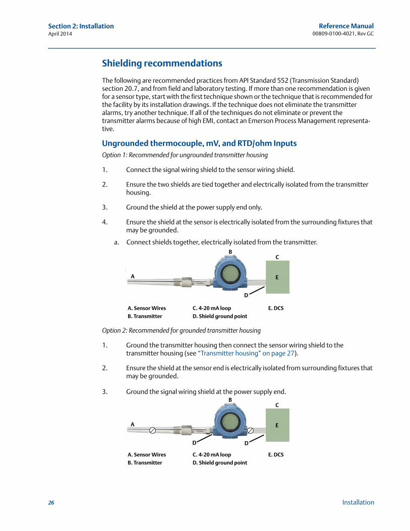
Ungrounded thermocouple, mV, and RTD/ohm InputsOption 1: Recommended for ungrounded transmitter housing
1. Connect the signal wiring shield to the sensor wiring shield.
2. Ensure the two shields are tied together and electrically isolated from the transmitter housing.
3. Ground the shield at the power supply end only.
4. Ensure the shield at the sensor is electrically isolated from the surrounding fixtures that may be grounded.
a. Connect shields together, electrically isolated from the transmitter.
Option 2: Recommended for grounded transmitter housing
1. Ground the transmitter housing then connect the sensor wiring shield to the transmitter housing (see “Transmitter housing” on page 27).
2. Ensure the shield at the sensor end is electrically isolated from surrounding fixtures that may be grounded.
3. Ground the signal wiring shield at the power supply end.
A. Sensor Wires C. 4-20 mA loop E. DCS
B. Transmitter D. Shield ground point
A. Sensor Wires C. 4-20 mA loop E. DCS
B. Transmitter D. Shield ground point
A
B
D
C
E
A
B
D
C
E
D
27
Reference Manual 00809-0100-4021, Rev GC
Section 2: InstallationApril 2014
Installation
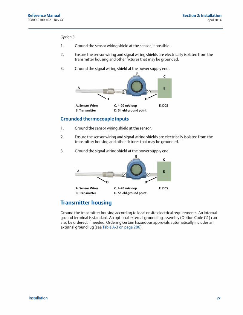
Option 3
1. Ground the sensor wiring shield at the sensor, if possible.
2. Ensure the sensor wiring and signal wiring shields are electrically isolated from the transmitter housing and other fixtures that may be grounded.
3. Ground the signal wiring shield at the power supply end.
Grounded thermocouple inputs
1. Ground the sensor wiring shield at the sensor.
2. Ensure the sensor wiring and signal wiring shields are electrically isolated from the transmitter housing and other fixtures that may be grounded.
3. Ground the signal wiring shield at the power supply end.
Transmitter housing
Ground the transmitter housing according to local or site electrical requirements. An internal ground terminal is standard. An optional external ground lug assembly (Option Code G1) can also be ordered, if needed. Ordering certain hazardous approvals automatically includes an external ground lug (see Table A-3 on page 206).
A. Sensor Wires C. 4-20 mA loop E. DCS
B. Transmitter D. Shield ground point
A. Sensor Wires C. 4-20 mA loop E. DCS
B. Transmitter D. Shield ground point
A
B
D
C
E
D
A
B
D
C
E
D

28
Reference Manual00809-0100-4021, Rev GC
Section 2: InstallationApril 2014
Installation
29
Reference Manual 00809-0100-4021, Rev GC
Section 3: HART commissioningApril 2014
HART® commissioning
Section 3 HART® commissioning
Overview . . . . . . . . . . . . . . . . . . . . . . . . . . . . . . . . . . . . . . . . . . . . . . . . . . . . . . . . . . . . . . . . . . page 29Confirm HART revision capability . . . . . . . . . . . . . . . . . . . . . . . . . . . . . . . . . . . . . . . . . . . . . page 29Safety messages . . . . . . . . . . . . . . . . . . . . . . . . . . . . . . . . . . . . . . . . . . . . . . . . . . . . . . . . . . . . page 30Field communicator . . . . . . . . . . . . . . . . . . . . . . . . . . . . . . . . . . . . . . . . . . . . . . . . . . . . . . . . . page 30Review configuration data . . . . . . . . . . . . . . . . . . . . . . . . . . . . . . . . . . . . . . . . . . . . . . . . . . . . page 40Check output . . . . . . . . . . . . . . . . . . . . . . . . . . . . . . . . . . . . . . . . . . . . . . . . . . . . . . . . . . . . . . . page 40Configuration . . . . . . . . . . . . . . . . . . . . . . . . . . . . . . . . . . . . . . . . . . . . . . . . . . . . . . . . . . . . . . page 40Device output configuration . . . . . . . . . . . . . . . . . . . . . . . . . . . . . . . . . . . . . . . . . . . . . . . . . . page 91Device information . . . . . . . . . . . . . . . . . . . . . . . . . . . . . . . . . . . . . . . . . . . . . . . . . . . . . . . . . . page 94Measurement filtering . . . . . . . . . . . . . . . . . . . . . . . . . . . . . . . . . . . . . . . . . . . . . . . . . . . . . . . page 95Diagnostics and service . . . . . . . . . . . . . . . . . . . . . . . . . . . . . . . . . . . . . . . . . . . . . . . . . . . . . . page 97Multidrop communication . . . . . . . . . . . . . . . . . . . . . . . . . . . . . . . . . . . . . . . . . . . . . . . . . . . page 98Use with the HART Tri-Loop . . . . . . . . . . . . . . . . . . . . . . . . . . . . . . . . . . . . . . . . . . . . . . . . . . page 99Calibration . . . . . . . . . . . . . . . . . . . . . . . . . . . . . . . . . . . . . . . . . . . . . . . . . . . . . . . . . . . . . . . . . page 121Trim the transmitter . . . . . . . . . . . . . . . . . . . . . . . . . . . . . . . . . . . . . . . . . . . . . . . . . . . . . . . . . page 122Troubleshooting . . . . . . . . . . . . . . . . . . . . . . . . . . . . . . . . . . . . . . . . . . . . . . . . . . . . . . . . . . . . page 133
3.1 OverviewThis section contains information on commissioning and tasks that should be performed on the bench prior to installation. This section contains 3144P HART configuration information only. The field communicator and instructions are given to perform configuration functions.
For convenience, field communicator fast key sequences are labeled “Fast Keys” for each software function below the appropriate headings.
AMS™ Device Manager help can be found in the AMS Device Manager on-line guides within the AMS Device Manager system.
3.2 Confirm HART revision capabilityIf using HART based control or asset management systems, confirm the HART capability of those systems prior to transmitter installation. Not all systems are capable of communicating with HART Revision 7 protocol. This transmitter can be configured for either HART Revision 5 or Revision 7.
Switch HART revision mode
If the HART configuration tool is not capable of communicating with HART Revision 7, the 3144P will load a generic menu with limited capability. The following procedures will switch the HART revision mode from the generic menu.
1. Manual Setup>Device Information>Identification>Message.
a. To change to HART Revision 5, Enter: “HART5” in the Message field
b. To change to HART Revision 7, Enter: “HART7” in the Message field
HART 7 Fast Keys 1, 2, 3, etc.
30
Reference Manual00809-0100-4021, Rev GC
Section 3: HART commissioningApril 2014
HART® commissioning
3.3 Safety messages
Instructions and procedures in this section may require special precautions to ensure the safety of the personnel performing the operations. Information that raises potential safety issues is indicated by a warning symbol ( ). Please refer to the following safety messages before performing an operation preceded by this symbol.
3.4 Field communicator
The Menu Tree and Fast Key sequences use the following device revisions:
Device Dashboard: Device Revision 5 and 6, DD v1
The field communicator exchanges information with the transmitter from the control room, the instrument site, or any wiring termination point in the loop. To facilitate communication, connect the field communicator in parallel with the transmitter (see Figure 2-11) using the loop connection ports on the top of the field communicator. The connections are non-polarized. Do not make connections to the NiCad recharger jack in explosive atmospheres. Before connecting the field communicator in an explosive atmosphere, make sure the instruments in the loop are installed according to intrinsically safe or non-incendive field wiring practices
3.4.1 Updating the HART communication software
The field communicator software may need to be updated to take advantage of the additional features available in the latest 3144P. Perform the following steps to determine if an upgrade is necessary.
1. Choose “Rosemount” from the list of manufacturers 5 and 6 and “3144 Temp” from the list of models.
2. If the Field Device Rev choices include “Dev v1,” “Dev v2,” “Dev v3,” or “Dev v4” (with any DD version), then the user will be able to connect to the device with reduced functionality. To unlock full functionality, download and install the new DD.
NoteThe original release of the safety-certified 3144P uses the name “3144P SIS” from the model list and requires “Dev v2, DD v1.”
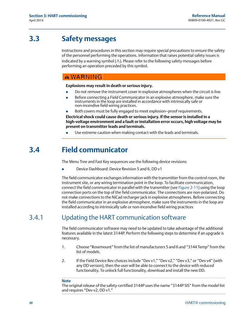
Explosions may result in death or serious injury.
Do not remove the instrument cover in explosive atmospheres when the circuit is live. Before connecting a Field Communicator in an explosive atmosphere, make sure the
instruments in the loop are installed in accordance with intrinsically safe or non-incendive field wiring practices.
Both covers must be fully engaged to meet explosion–proof requirements.Electrical shock could cause death or serious injury. If the sensor is installed in a high-voltage environment and a fault or installation error occurs, high voltage may be present on transmitter leads and terminals.
Use extreme caution when making contact with the leads and terminals.
31
Reference Manual 00809-0100-4021, Rev GC
Section 3: HART commissioningApril 2014
HART® commissioning
NoteIf communication is initiated with an improved 3144P using a communicator that only has a previous version of the transmitter device descriptors (DDs), the communicator will display the following message:
NOTICE: Upgrade to the field communicator software to access new XMTR functions.Continue with old description?
YES: The communicator will communicate properly with the transmitter using the existing transmitter DDs. However, new software features of the DD in the communicator will not be accessible.NO: The communicator will default to a generic transmitter functionality.
If YES is selected after the transmitter is configured to utilize the new features of the improved transmitters (such as Dual Input configuration or one of the added sensor input types–DIN Type L or DIN Type U), the user will experience trouble communicating with the transmitter and will be prompted to turn the communicator off. To prevent this from happening, either upgrade the communicator to the latest DD or answer NO to the above question and default to the generic transmitter functionality.
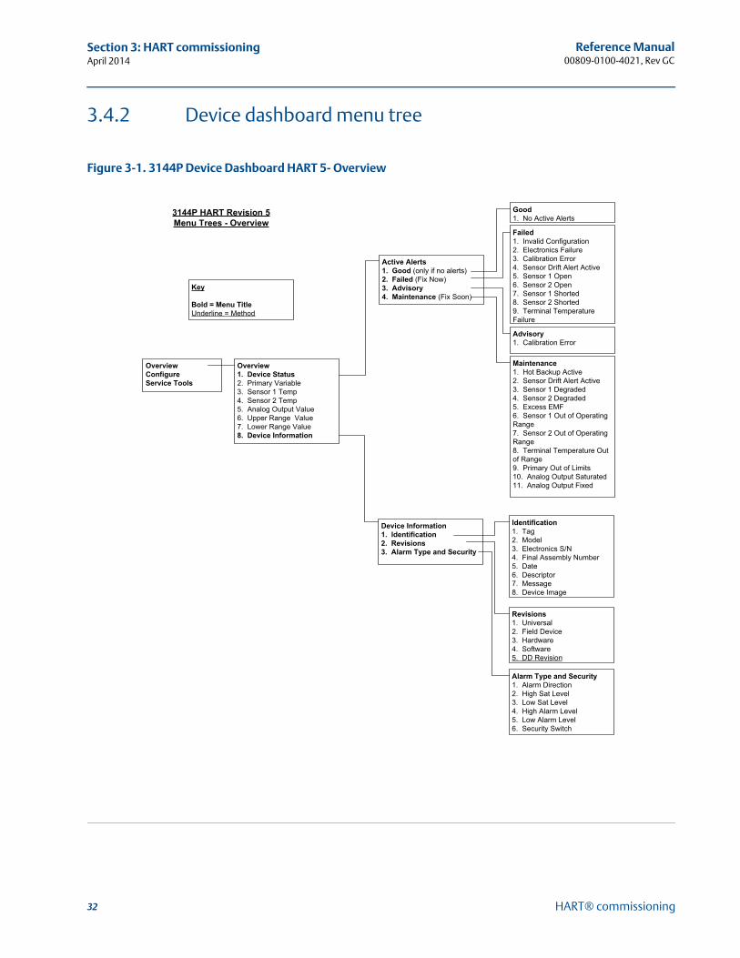
32
Reference Manual00809-0100-4021, Rev GC
Section 3: HART commissioningApril 2014
HART® commissioning
3.4.2 Device dashboard menu tree
Figure 3-1. 3144P Device Dashboard HART 5- Overview
OverviewConfigureService Tools
Active Alerts1. Good (only if no alerts)2. Failed (Fix Now)3. Advisory4. Maintenance (Fix Soon)
Failed1. Invalid Configuration2. Electronics Failure3. Calibration Error4. Sensor Drift Alert Active5. Sensor 1 Open6. Sensor 2 Open7. Sensor 1 Shorted8. Sensor 2 Shorted9. Terminal Temperature Failure
Advisory1. Calibration Error
Good1. No Active Alerts
Maintenance1. Hot Backup Active2. Sensor Drift Alert Active3. Sensor 1 Degraded4. Sensor 2 Degraded5. Excess EMF6. Sensor 1 Out of Operating Range7. Sensor 2 Out of Operating Range8. Terminal Temperature Out of Range9. Primary Out of Limits10. Analog Output Saturated11. Analog Output Fixed
Overview1. Device Status 2. Primary Variable 3. Sensor 1 Temp4. Sensor 2 Temp5. Analog Output Value6. Upper Range Value 7. Lower Range Value8. Device Information
Device Information1. Identification2. Revisions3. Alarm Type and Security
Revisions1. Universal2. Field Device3. Hardware4. Software5. DD Revision
Key
Bold = Menu TitleUnderline = Method
Identification1. Tag2. Model3. Electronics S/N4. Final Assembly Number5. Date6. Descriptor7. Message8. Device Image
Alarm Type and Security1. Alarm Direction2. High Sat Level3. Low Sat Level4. High Alarm Level5. Low Alarm Level6. Security Switch
3144P HART Revision 5 Menu Trees - Overview
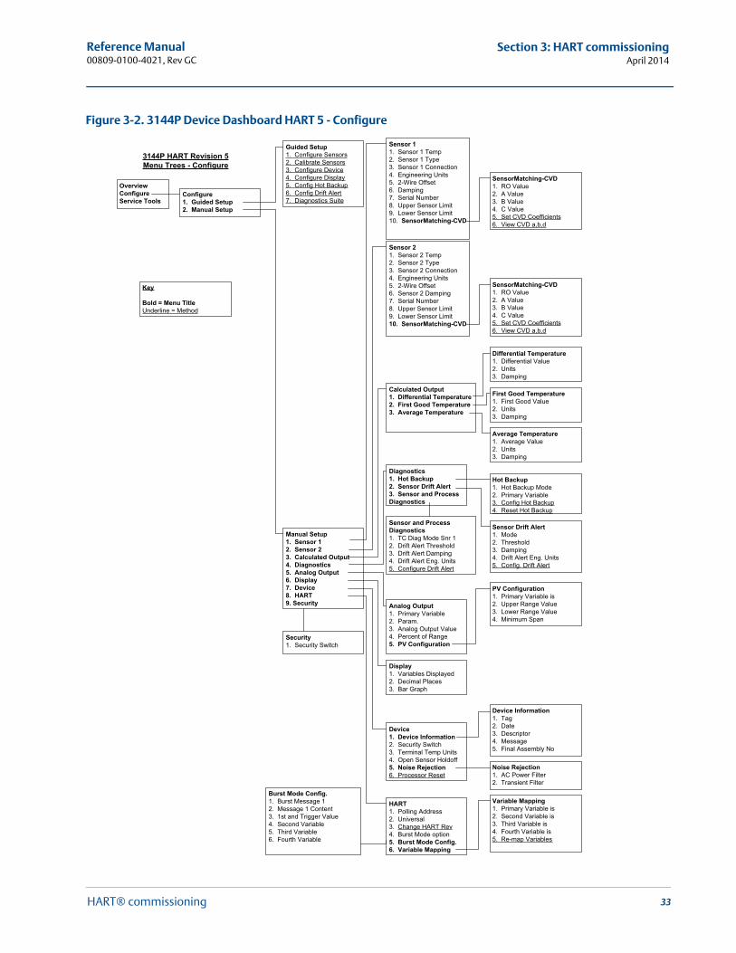
33
Reference Manual 00809-0100-4021, Rev GC
Section 3: HART commissioningApril 2014
HART® commissioning
Figure 3-2. 3144P Device Dashboard HART 5 - Configure
OverviewConfigureService Tools
Guided Setup1. Configure Sensors2. Calibrate Sensors3. Configure Device 4. Configure Display5. Config Hot Backup6. Config Drift Alert7. Diagnostics Suite
Manual Setup1. Sensor 12. Sensor 23. Calculated Output4. Diagnostics5. Analog Output6. Display7. Device8. HART9. Security
Configure1. Guided Setup2. Manual Setup
Sensor 11. Sensor 1 Temp2. Sensor 1 Type3. Sensor 1 Connection4. Engineering Units5. 2-Wire Offset6. Damping7. Serial Number8. Upper Sensor Limit9. Lower Sensor Limit10. SensorMatching-CVD
SensorMatching-CVD1. RO Value2. A Value3. B Value4. C Value5. Set CVD Coefficients6. View CVD a,b,d
Sensor 21. Sensor 2 Temp2. Sensor 2 Type3. Sensor 2 Connection4. Engineering Units5. 2-Wire Offset6. Sensor 2 Damping7. Serial Number8. Upper Sensor Limit9. Lower Sensor Limit10. SensorMatching-CVD
SensorMatching-CVD1. RO Value2. A Value3. B Value4. C Value5. Set CVD Coefficients6. View CVD a,b,d
Calculated Output1. Differential Temperature2. First Good Temperature3. Average Temperature
Diagnostics1. Hot Backup2. Sensor Drift Alert3. Sensor and Process Diagnostics
Display1. Variables Displayed2. Decimal Places3. Bar Graph
Device1. Device Information2. Security Switch3. Terminal Temp Units4. Open Sensor Holdoff5. Noise Rejection6. Processor Reset
Analog Output1. Primary Variable 2. Param.3. Analog Output Value4. Percent of Range5. PV Configuration
HART1. Polling Address2. Universal3. Change HART Rev4. Burst Mode option5. Burst Mode Config.6. Variable Mapping
Differential Temperature1. Differential Value2. Units3. Damping
First Good Temperature1. First Good Value2. Units3. Damping
Average Temperature1. Average Value 2. Units3. Damping
Hot Backup1. Hot Backup Mode2. Primary Variable 3. Config Hot Backup4. Reset Hot Backup
Sensor Drift Alert1. Mode2. Threshold3. Damping4. Drift Alert Eng. Units5. Config. Drift Alert
PV Configuration1. Primary Variable is2. Upper Range Value3. Lower Range Value4. Minimum Span
Device Information1. Tag2. Date3. Descriptor4. Message5. Final Assembly No
Noise Rejection1. AC Power Filter2. Transient Filter
Variable Mapping1. Primary Variable is2. Second Variable is3. Third Variable is4. Fourth Variable is5. Re-map Variables
Security1. Security Switch
Sensor and Process Diagnostics1. TC Diag Mode Snr 12. Drift Alert Threshold3. Drift Alert Damping4. Drift Alert Eng. Units5. Configure Drift Alert
Burst Mode Config.1. Burst Message 12. Message 1 Content3. 1st and Trigger Value4. Second Variable5. Third Variable6. Fourth Variable
Key
Bold = Menu TitleUnderline = Method
3144P HART Revision 5 Menu Trees - Configure
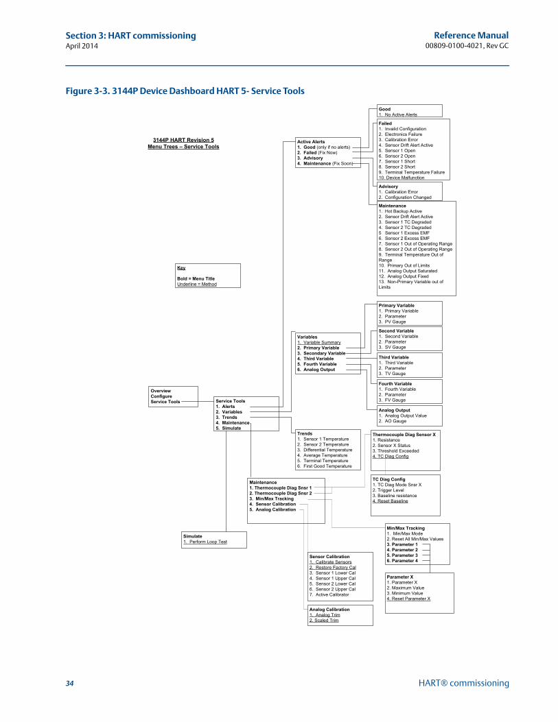
34
Reference Manual00809-0100-4021, Rev GC
Section 3: HART commissioningApril 2014
HART® commissioning
Figure 3-3. 3144P Device Dashboard HART 5- Service Tools
OverviewConfigureService Tools Service Tools
1. Alerts2. Variables3. Trends4. Maintenance5. Simulate
Variables1. Variable Summary2. Primary Variable3. Secondary Variable4. Third Variable5. Fourth Variable6. Analog Output
Trends1. Sensor 1 Temperature2. Sensor 2 Temperature3. Differential Temperature4. Average Temperature5. Terminal Temperature6. First Good Temperature
Primary Variable1. Primary Variable 2. Parameter3. PV Gauge
Second Variable1. Second Variable 2. Parameter3. SV Gauge
Third Variable1. Third Variable 2. Parameter3. TV Gauge
Fourth Variable1. Fourth Variable 2. Parameter3. FV Gauge
Analog Output1. Analog Output Value2. AO Gauge
Maintenance1. Thermocouple Diag Snsr 12. Thermocouple Diag Snsr 23. Min/Max Tracking4. Sensor Calibration5. Analog Calibration
Simulate1. Perform Loop Test
Sensor Calibration1. Calibrate Sensors2. Restore Factory Cal3. Sensor 1 Lower Cal4. Sensor 1 Upper Cal5. Sensor 2 Lower Cal6. Sensor 2 Upper Cal7. Active Calibrator
Active Alerts1. Good (only if no alerts)2. Failed (Fix Now)3. Advisory4. Maintenance (Fix Soon)
Failed1. Invalid Configuration2. Electronics Failure3. Calibration Error4. Sensor Drift Alert Active5. Sensor 1 Open6. Sensor 2 Open7. Sensor 1 Short8. Sensor 2 Short9. Terminal Temperature Failure10. Device Malfunction
Advisory1. Calibration Error2. Configuration Changed
Good1. No Active Alerts
Maintenance1. Hot Backup Active2. Sensor Drift Alert Active3. Sensor 1 TC Degraded4. Sensor 2 TC Degraded5 Sensor 1 Excess EMF6. Sensor 2 Excess EMF7. Sensor 1 Out of Operating Range8. Sensor 2 Out of Operating Range9. Terminal Temperature Out of Range10. Primary Out of Limits11. Analog Output Saturated12. Analog Output Fixed13. Non-Primary Variable out of Limits
Analog Calibration1. Analog Trim2. Scaled Trim
Thermocouple Diag Sensor X1. Resistance2. Sensor X Status3. Threshold Exceeded4. TC Diag Config
TC Diag Config1. TC Diag Mode Snsr X2. Trigger Level3. Baseline resistance4. Reset Baseline
Min/Max Tracking1. Min/Max Mode2. Reset All Min/Max Values3. Parameter 14. Parameter 25. Parameter 36. Parameter 4
Parameter X1. Parameter X2. Maximum Value3. Minimum Value4. Reset Parameter X
Key
Bold = Menu TitleUnderline = Method
3144P HART Revision 5 Menu Trees – Service Tools
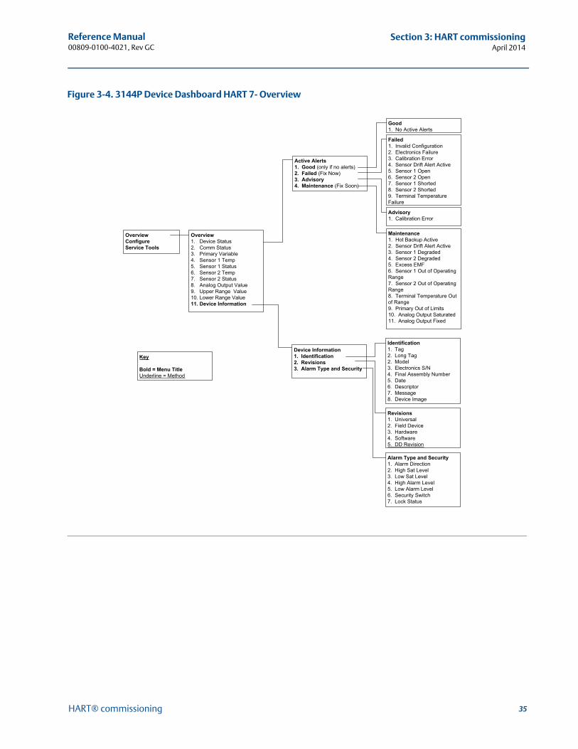
35
Reference Manual 00809-0100-4021, Rev GC
Section 3: HART commissioningApril 2014
HART® commissioning
Figure 3-4. 3144P Device Dashboard HART 7- Overview
OverviewConfigureService Tools
Active Alerts1. Good (only if no alerts)2. Failed (Fix Now)3. Advisory4. Maintenance (Fix Soon)
Failed1. Invalid Configuration2. Electronics Failure3. Calibration Error4. Sensor Drift Alert Active5. Sensor 1 Open6. Sensor 2 Open7. Sensor 1 Shorted8. Sensor 2 Shorted9. Terminal Temperature Failure
Advisory1. Calibration Error
Good1. No Active Alerts
Maintenance1. Hot Backup Active2. Sensor Drift Alert Active3. Sensor 1 Degraded4. Sensor 2 Degraded5. Excess EMF6. Sensor 1 Out of Operating Range7. Sensor 2 Out of Operating Range8. Terminal Temperature Out of Range9. Primary Out of Limits10. Analog Output Saturated11. Analog Output Fixed
Overview1. Device Status2. Comm Status 3. Primary Variable 4. Sensor 1 Temp5. Sensor 1 Status6. Sensor 2 Temp7. Sensor 2 Status8. Analog Output Value9. Upper Range Value 10. Lower Range Value11. Device Information
Device Information1. Identification2. Revisions3. Alarm Type and Security
Revisions1. Universal2. Field Device3. Hardware4. Software5. DD Revision
Key
Bold = Menu TitleUnderline = Method
Identification1. Tag2. Long Tag2. Model3. Electronics S/N4. Final Assembly Number5. Date6. Descriptor7. Message8. Device Image
Alarm Type and Security1. Alarm Direction2. High Sat Level3. Low Sat Level4. High Alarm Level5. Low Alarm Level6. Security Switch7. Lock Status
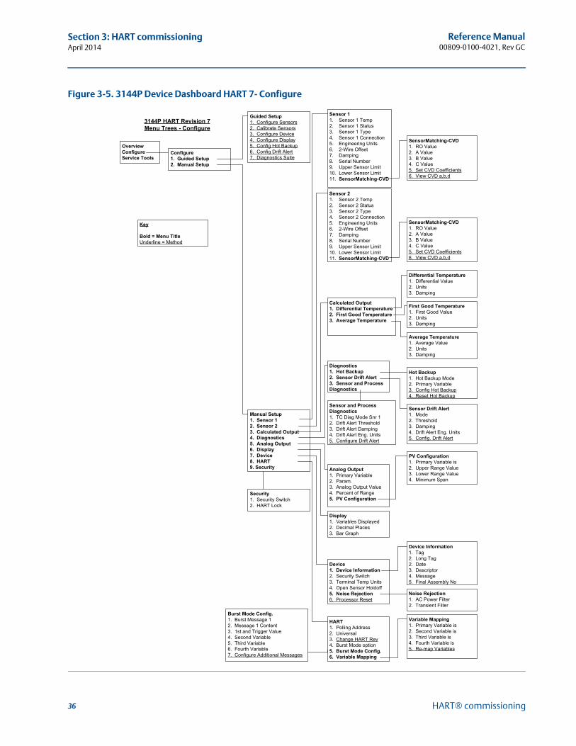
36
Reference Manual00809-0100-4021, Rev GC
Section 3: HART commissioningApril 2014
HART® commissioning
Figure 3-5. 3144P Device Dashboard HART 7- Configure
OverviewConfigureService Tools
Guided Setup1. Configure Sensors2. Calibrate Sensors3. Configure Device 4. Configure Display5. Config Hot Backup6. Config Drift Alert7. Diagnostics Suite
Manual Setup1. Sensor 12. Sensor 23. Calculated Output4. Diagnostics5. Analog Output6. Display7. Device8. HART9. Security
Configure1. Guided Setup2. Manual Setup
Sensor 11. Sensor 1 Temp2. Sensor 1 Status3. Sensor 1 Type4. Sensor 1 Connection5. Engineering Units6. 2-Wire Offset7. Damping8. Serial Number9. Upper Sensor Limit10. Lower Sensor Limit11. SensorMatching-CVD
SensorMatching-CVD1. RO Value2. A Value3. B Value4. C Value5. Set CVD Coefficients6. View CVD a,b,d
Sensor 21. Sensor 2 Temp2. Sensor 2 Status3. Sensor 2 Type4. Sensor 2 Connection5. Engineering Units6. 2-Wire Offset7. Damping8. Serial Number9. Upper Sensor Limit10. Lower Sensor Limit11. SensorMatching-CVD
SensorMatching-CVD1. RO Value2. A Value3. B Value4. C Value5. Set CVD Coefficients6. View CVD a,b,d
Calculated Output1. Differential Temperature2. First Good Temperature3. Average Temperature
Diagnostics1. Hot Backup2. Sensor Drift Alert3. Sensor and Process Diagnostics
Display1. Variables Displayed2. Decimal Places3. Bar Graph
Device1. Device Information2. Security Switch3. Terminal Temp Units4. Open Sensor Holdoff5. Noise Rejection6. Processor Reset
Analog Output1. Primary Variable 2. Param.3. Analog Output Value4. Percent of Range5. PV Configuration
HART1. Polling Address2. Universal3. Change HART Rev4. Burst Mode option5. Burst Mode Config.6. Variable Mapping
Differential Temperature1. Differential Value2. Units3. Damping
First Good Temperature1. First Good Value2. Units3. Damping
Average Temperature1. Average Value 2. Units3. Damping
Hot Backup1. Hot Backup Mode2. Primary Variable 3. Config Hot Backup4. Reset Hot Backup
Sensor Drift Alert1. Mode2. Threshold3. Damping4. Drift Alert Eng. Units5. Config. Drift Alert
PV Configuration1. Primary Variable is2. Upper Range Value3. Lower Range Value4. Minimum Span
Device Information1. Tag2. Long Tag2. Date3. Descriptor4. Message5. Final Assembly No
Noise Rejection1. AC Power Filter2. Transient Filter
Variable Mapping1. Primary Variable is2. Second Variable is3. Third Variable is4. Fourth Variable is5. Re-map Variables
Security1. Security Switch2. HART Lock
Sensor and Process Diagnostics1. TC Diag Mode Snr 12. Drift Alert Threshold3. Drift Alert Damping4. Drift Alert Eng. Units5. Configure Drift Alert
Burst Mode Config.1. Burst Message 12. Message 1 Content3. 1st and Trigger Value4. Second Variable5. Third Variable6. Fourth Variable7. Configure Additional Messages
Key
Bold = Menu TitleUnderline = Method
3144P HART Revision 7 Menu Trees - Configure
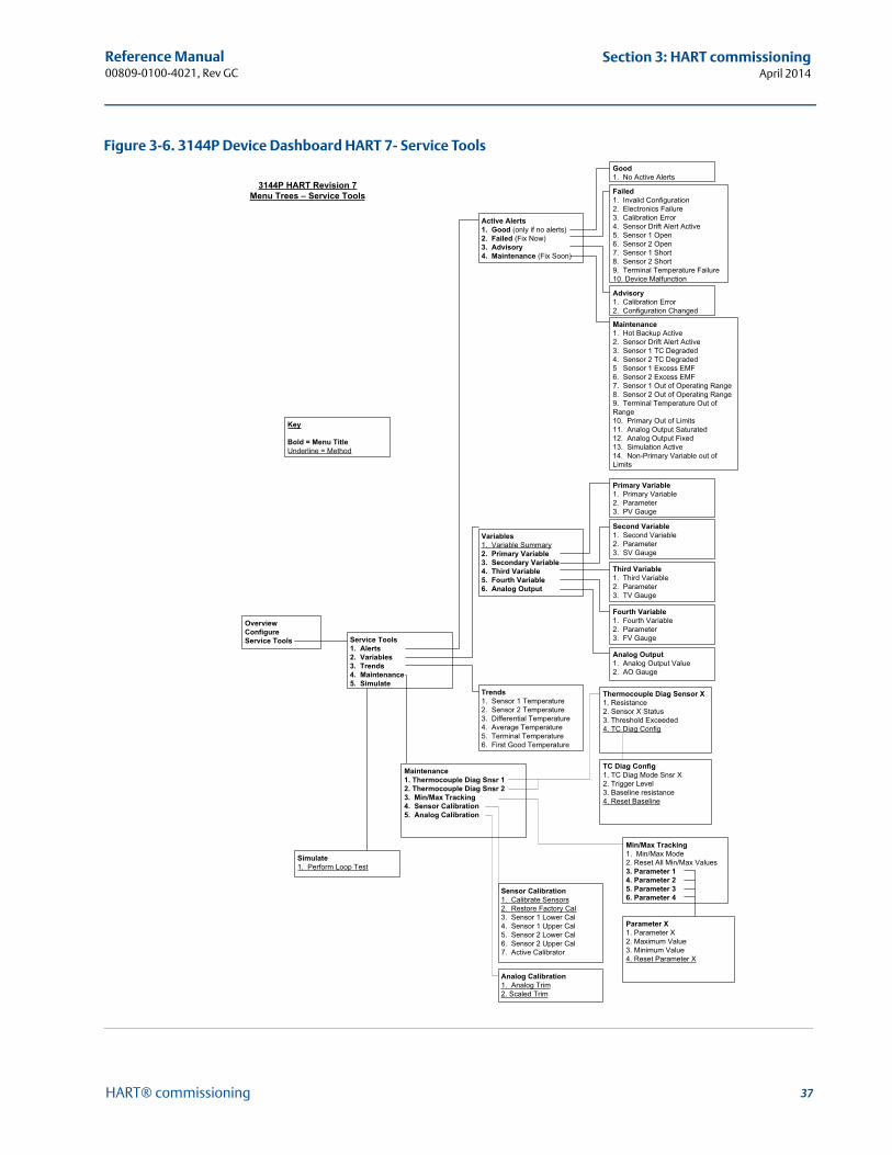
37
Reference Manual 00809-0100-4021, Rev GC
Section 3: HART commissioningApril 2014
HART® commissioning
Figure 3-6. 3144P Device Dashboard HART 7- Service Tools
OverviewConfigureService Tools Service Tools
1. Alerts2. Variables3. Trends4. Maintenance5. Simulate
Variables1. Variable Summary2. Primary Variable3. Secondary Variable4. Third Variable5. Fourth Variable6. Analog Output
Trends1. Sensor 1 Temperature2. Sensor 2 Temperature3. Differential Temperature4. Average Temperature5. Terminal Temperature6. First Good Temperature
Primary Variable1. Primary Variable 2. Parameter3. PV Gauge
Second Variable1. Second Variable 2. Parameter3. SV Gauge
Third Variable1. Third Variable 2. Parameter3. TV Gauge
Fourth Variable1. Fourth Variable 2. Parameter3. FV Gauge
Analog Output1. Analog Output Value2. AO Gauge
Maintenance1. Thermocouple Diag Snsr 12. Thermocouple Diag Snsr 23. Min/Max Tracking4. Sensor Calibration5. Analog Calibration
Simulate1. Perform Loop Test
Sensor Calibration1. Calibrate Sensors2. Restore Factory Cal3. Sensor 1 Lower Cal4. Sensor 1 Upper Cal5. Sensor 2 Lower Cal6. Sensor 2 Upper Cal7. Active Calibrator
Active Alerts1. Good (only if no alerts)2. Failed (Fix Now)3. Advisory4. Maintenance (Fix Soon)
Failed1. Invalid Configuration2. Electronics Failure3. Calibration Error4. Sensor Drift Alert Active5. Sensor 1 Open6. Sensor 2 Open7. Sensor 1 Short8. Sensor 2 Short9. Terminal Temperature Failure10. Device Malfunction
Advisory1. Calibration Error2. Configuration Changed
Good1. No Active Alerts
Maintenance1. Hot Backup Active2. Sensor Drift Alert Active3. Sensor 1 TC Degraded4. Sensor 2 TC Degraded5 Sensor 1 Excess EMF6. Sensor 2 Excess EMF7. Sensor 1 Out of Operating Range8. Sensor 2 Out of Operating Range9. Terminal Temperature Out of Range10. Primary Out of Limits11. Analog Output Saturated12. Analog Output Fixed13. Simulation Active14. Non-Primary Variable out of Limits
Analog Calibration1. Analog Trim2. Scaled Trim
Thermocouple Diag Sensor X1. Resistance2. Sensor X Status3. Threshold Exceeded4. TC Diag Config
TC Diag Config1. TC Diag Mode Snsr X2. Trigger Level3. Baseline resistance4. Reset Baseline
Min/Max Tracking1. Min/Max Mode2. Reset All Min/Max Values3. Parameter 14. Parameter 25. Parameter 36. Parameter 4
Parameter X1. Parameter X2. Maximum Value3. Minimum Value4. Reset Parameter X
Key
Bold = Menu TitleUnderline = Method
3144P HART Revision 7 Menu Trees – Service Tools
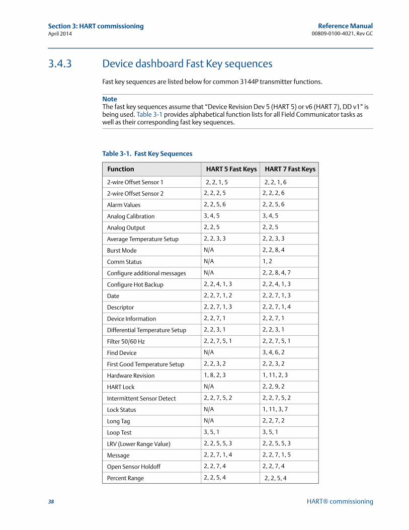
38
Reference Manual00809-0100-4021, Rev GC
Section 3: HART commissioningApril 2014
HART® commissioning
3.4.3 Device dashboard Fast Key sequences
Fast key sequences are listed below for common 3144P transmitter functions.
NoteThe fast key sequences assume that “Device Revision Dev 5 (HART 5) or v6 (HART 7), DD v1” is being used. Table 3-1 provides alphabetical function lists for all Field Communicator tasks as well as their corresponding fast key sequences.
Table 3-1. Fast Key Sequences
Function HART 5 Fast Keys HART 7 Fast Keys
2-wire Offset Sensor 1 2, 2, 1, 5 2, 2, 1, 6
2-wire Offset Sensor 2 2, 2, 2, 5 2, 2, 2, 6
Alarm Values 2, 2, 5, 6 2, 2, 5, 6
Analog Calibration 3, 4, 5 3, 4, 5
Analog Output 2, 2, 5 2, 2, 5
Average Temperature Setup 2, 2, 3, 3 2, 2, 3, 3
Burst Mode N/A 2, 2, 8, 4
Comm Status N/A 1, 2
Configure additional messages N/A 2, 2, 8, 4, 7
Configure Hot Backup 2, 2, 4, 1, 3 2, 2, 4, 1, 3
Date 2, 2, 7, 1, 2 2, 2, 7, 1, 3
Descriptor 2, 2, 7, 1, 3 2, 2, 7, 1, 4
Device Information 2, 2, 7, 1 2, 2, 7, 1
Differential Temperature Setup 2, 2, 3, 1 2, 2, 3, 1
Filter 50/60 Hz 2, 2, 7, 5, 1 2, 2, 7, 5, 1
Find Device N/A 3, 4, 6, 2
First Good Temperature Setup 2, 2, 3, 2 2, 2, 3, 2
Hardware Revision 1, 8, 2, 3 1, 11, 2, 3
HART Lock N/A 2, 2, 9, 2
Intermittent Sensor Detect 2, 2, 7, 5, 2 2, 2, 7, 5, 2
Lock Status N/A 1, 11, 3, 7
Long Tag N/A 2, 2, 7, 2
Loop Test 3, 5, 1 3, 5, 1
LRV (Lower Range Value) 2, 2, 5, 5, 3 2, 2, 5, 5, 3
Message 2, 2, 7, 1, 4 2, 2, 7, 1, 5
Open Sensor Holdoff 2, 2, 7, 4 2, 2, 7, 4
Percent Range 2, 2, 5, 4 2, 2, 5, 4
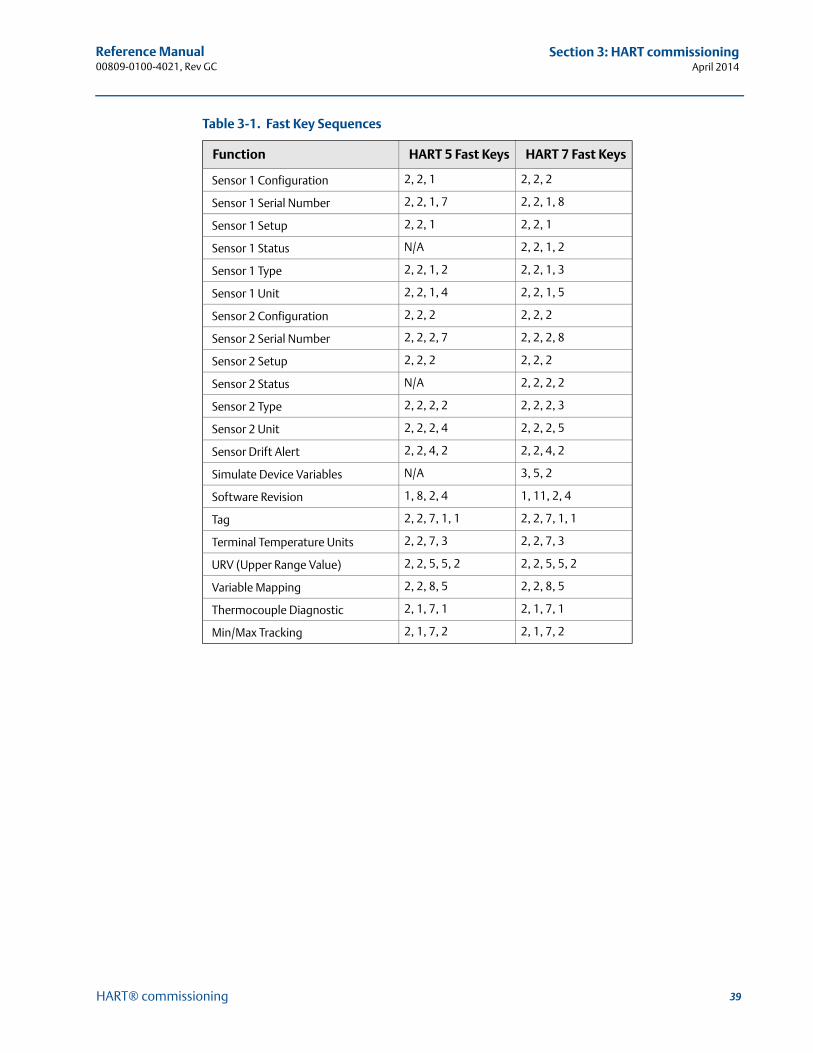
39
Reference Manual 00809-0100-4021, Rev GC
Section 3: HART commissioningApril 2014
HART® commissioning
Function HART 5 Fast Keys HART 7 Fast Keys
Sensor 1 Configuration 2, 2, 1 2, 2, 2
Sensor 1 Serial Number 2, 2, 1, 7 2, 2, 1, 8
Sensor 1 Setup 2, 2, 1 2, 2, 1
Sensor 1 Status N/A 2, 2, 1, 2
Sensor 1 Type 2, 2, 1, 2 2, 2, 1, 3
Sensor 1 Unit 2, 2, 1, 4 2, 2, 1, 5
Sensor 2 Configuration 2, 2, 2 2, 2, 2
Sensor 2 Serial Number 2, 2, 2, 7 2, 2, 2, 8
Sensor 2 Setup 2, 2, 2 2, 2, 2
Sensor 2 Status N/A 2, 2, 2, 2
Sensor 2 Type 2, 2, 2, 2 2, 2, 2, 3
Sensor 2 Unit 2, 2, 2, 4 2, 2, 2, 5
Sensor Drift Alert 2, 2, 4, 2 2, 2, 4, 2
Simulate Device Variables N/A 3, 5, 2
Software Revision 1, 8, 2, 4 1, 11, 2, 4
Tag 2, 2, 7, 1, 1 2, 2, 7, 1, 1
Terminal Temperature Units 2, 2, 7, 3 2, 2, 7, 3
URV (Upper Range Value) 2, 2, 5, 5, 2 2, 2, 5, 5, 2
Variable Mapping 2, 2, 8, 5 2, 2, 8, 5
Thermocouple Diagnostic 2, 1, 7, 1 2, 1, 7, 1
Min/Max Tracking 2, 1, 7, 2 2, 1, 7, 2
Table 3-1. Fast Key Sequences
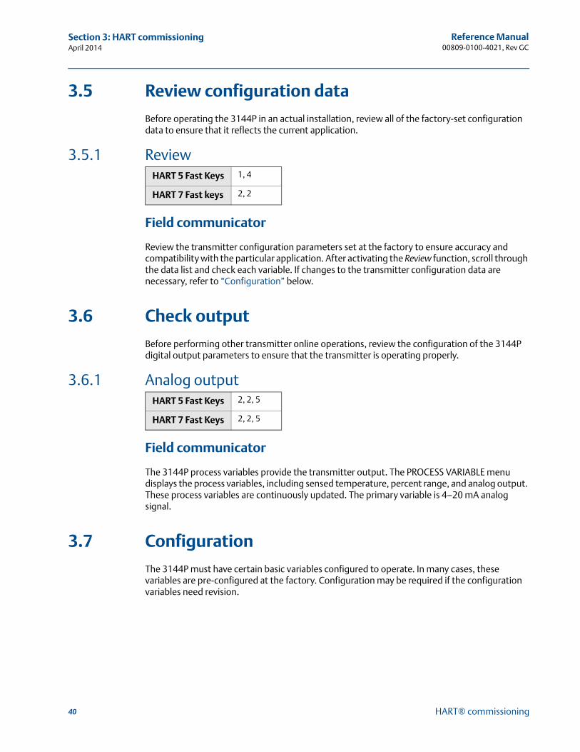
40
Reference Manual00809-0100-4021, Rev GC
Section 3: HART commissioningApril 2014
HART® commissioning
3.5 Review configuration data
Before operating the 3144P in an actual installation, review all of the factory-set configuration data to ensure that it reflects the current application.
3.5.1 Review
Field communicator
Review the transmitter configuration parameters set at the factory to ensure accuracy and compatibility with the particular application. After activating the Review function, scroll through the data list and check each variable. If changes to the transmitter configuration data are necessary, refer to “Configuration” below.
3.6 Check output
Before performing other transmitter online operations, review the configuration of the 3144P digital output parameters to ensure that the transmitter is operating properly.
3.6.1 Analog output
Field communicator
The 3144P process variables provide the transmitter output. The PROCESS VARIABLE menu displays the process variables, including sensed temperature, percent range, and analog output. These process variables are continuously updated. The primary variable is 4–20 mA analog signal.
3.7 Configuration
The 3144P must have certain basic variables configured to operate. In many cases, these variables are pre-configured at the factory. Configuration may be required if the configuration variables need revision.
HART 5 Fast Keys 1, 4
HART 7 Fast keys 2, 2
HART 5 Fast Keys 2, 2, 5
HART 7 Fast Keys 2, 2, 5
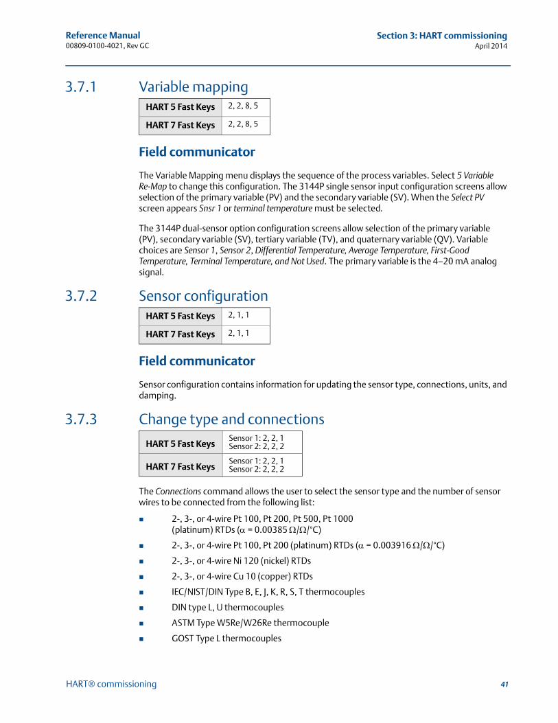
41
Reference Manual 00809-0100-4021, Rev GC
Section 3: HART commissioningApril 2014
HART® commissioning
3.7.1 Variable mapping
Field communicator
The Variable Mapping menu displays the sequence of the process variables. Select 5 Variable Re-Map to change this configuration. The 3144P single sensor input configuration screens allow selection of the primary variable (PV) and the secondary variable (SV). When the Select PV screen appears Snsr 1 or terminal temperature must be selected.
The 3144P dual-sensor option configuration screens allow selection of the primary variable (PV), secondary variable (SV), tertiary variable (TV), and quaternary variable (QV). Variable choices are Sensor 1, Sensor 2, Differential Temperature, Average Temperature, First-Good Temperature, Terminal Temperature, and Not Used. The primary variable is the 4–20 mA analog signal.
3.7.2 Sensor configuration
Field communicator
Sensor configuration contains information for updating the sensor type, connections, units, and damping.
3.7.3 Change type and connections
The Connections command allows the user to select the sensor type and the number of sensor wires to be connected from the following list:
2-, 3-, or 4-wire Pt 100, Pt 200, Pt 500, Pt 1000(platinum) RTDs ( = 0.00385 //°C)
2-, 3-, or 4-wire Pt 100, Pt 200 (platinum) RTDs ( = 0.003916 //°C)
2-, 3-, or 4-wire Ni 120 (nickel) RTDs
2-, 3-, or 4-wire Cu 10 (copper) RTDs
IEC/NIST/DIN Type B, E, J, K, R, S, T thermocouples
DIN type L, U thermocouples
ASTM Type W5Re/W26Re thermocouple
GOST Type L thermocouples
HART 5 Fast Keys 2, 2, 8, 5
HART 7 Fast Keys 2, 2, 8, 5
HART 5 Fast Keys 2, 1, 1
HART 7 Fast Keys 2, 1, 1
HART 5 Fast KeysSensor 1: 2, 2, 1Sensor 2: 2, 2, 2
HART 7 Fast KeysSensor 1: 2, 2, 1Sensor 2: 2, 2, 2
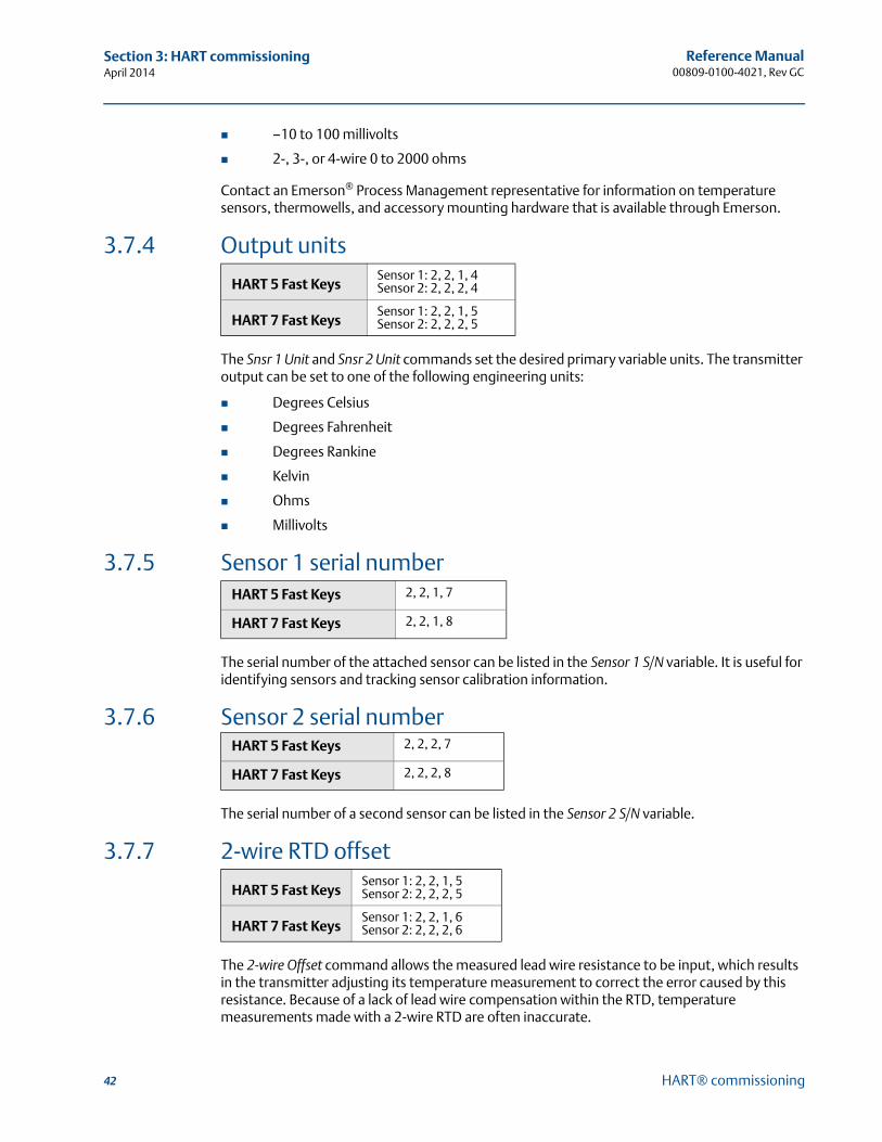
42
Reference Manual00809-0100-4021, Rev GC
Section 3: HART commissioningApril 2014
HART® commissioning
–10 to 100 millivolts
2-, 3-, or 4-wire 0 to 2000 ohms
Contact an Emerson® Process Management representative for information on temperature sensors, thermowells, and accessory mounting hardware that is available through Emerson.
3.7.4 Output units
The Snsr 1 Unit and Snsr 2 Unit commands set the desired primary variable units. The transmitter output can be set to one of the following engineering units:
Degrees Celsius
Degrees Fahrenheit
Degrees Rankine
Kelvin
Ohms
Millivolts
3.7.5 Sensor 1 serial number
The serial number of the attached sensor can be listed in the Sensor 1 S/N variable. It is useful for identifying sensors and tracking sensor calibration information.
3.7.6 Sensor 2 serial number
The serial number of a second sensor can be listed in the Sensor 2 S/N variable.
3.7.7 2-wire RTD offset
The 2-wire Offset command allows the measured lead wire resistance to be input, which results in the transmitter adjusting its temperature measurement to correct the error caused by this resistance. Because of a lack of lead wire compensation within the RTD, temperature measurements made with a 2-wire RTD are often inaccurate.
HART 5 Fast KeysSensor 1: 2, 2, 1, 4Sensor 2: 2, 2, 2, 4
HART 7 Fast KeysSensor 1: 2, 2, 1, 5Sensor 2: 2, 2, 2, 5
HART 5 Fast Keys 2, 2, 1, 7
HART 7 Fast Keys 2, 2, 1, 8
HART 5 Fast Keys 2, 2, 2, 7
HART 7 Fast Keys 2, 2, 2, 8
HART 5 Fast KeysSensor 1: 2, 2, 1, 5Sensor 2: 2, 2, 2, 5
HART 7 Fast KeysSensor 1: 2, 2, 1, 6Sensor 2: 2, 2, 2, 6
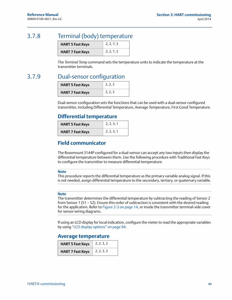
43
Reference Manual 00809-0100-4021, Rev GC
Section 3: HART commissioningApril 2014
HART® commissioning
3.7.8 Terminal (body) temperature
The Terminal Temp command sets the temperature units to indicate the temperature at the transmitter terminals.
3.7.9 Dual-sensor configuration
Dual-sensor configuration sets the functions that can be used with a dual-sensor configured transmitter, including Differential Temperature, Average Temperature, First Good Temperature.
Differential temperature
Field communicator
The Rosemount 3144P configured for a dual-sensor can accept any two inputs then display the differential temperature between them. Use the following procedure with Traditional Fast Keys to configure the transmitter to measure differential temperature:
NoteThis procedure reports the differential temperature as the primary variable analog signal. If this is not needed, assign differential temperature to the secondary, tertiary, or quaternary variable.
NoteThe transmitter determines the differential temperature by subtracting the reading of Sensor 2 from Sensor 1 (S1 – S2). Ensure this order of subtraction is consistent with the desired reading for the application. Refer to Figure 2-3 on page 14, or inside the transmitter terminal-side cover for sensor wiring diagrams.
If using an LCD display for local indication, configure the meter to read the appropriate variables by using “LCD display options” on page 94.
Average temperature
HART 5 Fast Keys 2, 2, 7, 3
HART 7 Fast Keys 2, 2, 7, 3
HART 5 Fast Keys 2, 2, 3
HART 7 Fast Keys 2, 2, 3
HART 5 Fast Keys 2, 2, 3, 1
HART 7 Fast Keys 2, 2, 3, 1
HART 5 Fast Keys 2, 2, 3, 3
HART 7 Fast Keys 2, 2, 3, 3
44
Reference Manual00809-0100-4021, Rev GC
Section 3: HART commissioningApril 2014
HART® commissioning
Field communicator
The 3144P transmitter configured for dual-sensors can output and display the average temperature of any two inputs. Use the following procedure with Traditional Fast Keys to configure the transmitter to measure the average temperature:
Configure Sensor 1 and Sensor 2 appropriately. Select 1 Device Setup, 3 Configuration, 2 Sensor Configuration, 1 Change Type and Conn. to set the sensor type and number of wires for Sensor 1. Repeat for Sensor 2.
NoteThis procedure configures the average temperature as the primary variable analog signal. If this is not needed, assign the average temperature to the secondary, tertiary, or quaternary variable.
If using an LCD display, configure it to read the appropriate variables using “LCD display options” on page 94.
NoteIf Sensor 1 and/or Sensor 2 should fail while PV is configured for average temperature and the Hot Backup™ feature is not enabled, the transmitter will go into alarm. For this reason, it is recommended when PV is Sensor Average, that the Hot Backup feature be enabled when dual-element sensors are used, or when two temperature measurements are taken from the same point in the process. If a sensor failure occurs when the Hot Backup feature is enabled, while PV is Sensor Average, three scenarios could result: If Sensor 1 fails, the average will only be reading from Sensor 2, the working sensor
If Sensor 2 fails, the average will only be reading from Sensor 1, the working sensor
If both sensors fail simultaneously, the transmitter will go into alarm and the status available (via HART) states that both Sensor 1 and Sensor 2 have failed
In the first two scenarios, the 4-20 mA signal is not disrupted and the status available to the control system (via HART) specifies which sensor has failed.
First good configuration
Field communicator
The First Good device variable is useful for applications where dual-sensors (or a single dual element sensor) are used in a single process. The first good variable will report the Sensor 1 value, unless Sensor 1 fails. When Sensor 1 fails, the Sensor 2 value will be reported as the first good variable. Once the first good variable has switched to Sensor 2, it will not revert back to Sensor 1 until a master reset occurs or “Suspend Non-PV alarms” is disabled. When the PV is mapped to first good variable and either Sensor 1 or Sensor 2 fails, the analog output will go to the alarm level, but the digital PV value read through the HART interface will still report the proper first good sensor value.
If the user does not want the transmitter to go into analog output alarm when the PV is mapped to first good and Sensor 1 fails, enable “Suspend Non-PV Alarm” mode. This combination prevents the analog output from going to the alarm level unless BOTH sensors fail.
HART 5 Fast Keys 2, 2, 3, 2
HART 7 Fast Keys 2, 2, 3, 2
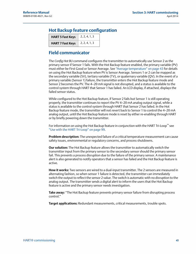
45
Reference Manual 00809-0100-4021, Rev GC
Section 3: HART commissioningApril 2014
HART® commissioning
Hot Backup feature configuration
Field communicator
The Config Hot BU command configures the transmitter to automatically use Sensor 2 as the primary sensor if Sensor 1 fails. With the Hot Backup feature enabled, the primary variable (PV) must either be First Good or Sensor Average. See “Average temperature” on page 43 for details on using the Hot Backup feature when PV is Sensor Average. Sensors 1 or 2 can be mapped as the secondary variable (SV), tertiary variable (TV), or quaternary variable (QV). In the event of a primary variable (Sensor 1) failure, the transmitter enters the Hot Backup feature mode and Sensor 2 becomes the PV. The 4–20 mA signal is not disrupted, and a status is available to the control system through HART that Sensor 1 has failed. An LCD display, if attached, displays the failed sensor status.
While configured to the Hot Backup feature, if Sensor 2 fails but Sensor 1 is still operating properly, the transmitter continues to report the PV 4–20 mA analog output signal, while a status is available to the control system through HART that Sensor 2 has failed. In the Hot Backup feature mode, the transmitter will not revert back to Sensor 1 to control the 4–20 mA analog output, until the Hot Backup feature mode is reset by either re-enabling through HART or by briefly powering down the transmitter.
For information on using the Hot Backup feature in conjunction with the HART Tri-Loop™ see “Use with the HART Tri-Loop” on page 99.
Problem description: The unexpected failure of a critical temperature measurement can cause safety issues, environmental or regulatory concerns, and process shutdowns.
Our solution: The Hot Backup feature allows the transmitter to automatically switch the transmitter input from the primary sensor to the secondary sensor should the primary sensor fail. This prevents a process disruption due to the failure of the primary sensor. A maintenance alert is also generated to notify operators that a sensor has failed and the Hot Backup feature is active.
How it works: Two sensors are wired to a dual-input transmitter. The 2 sensors are measured in alternating fashion, so when sensor 1 failure is detected, the transmitter can immediately switch the output to reflect the sensor 2 value. The switch is automatic with no disruption to the analog output. The transmitter sends a digital alert to inform the users that the Hot Backup feature is active and the primary sensor needs investigation.
Take away: “The Hot Backup feature prevents primary sensor failure from disrupting process control.”
Target applications: Redundant measurements, critical measurements, trouble spots.
HART 5 Fast Keys 2, 2, 4, 1, 3
HART 7 Fast Keys 2, 2, 4, 1, 3
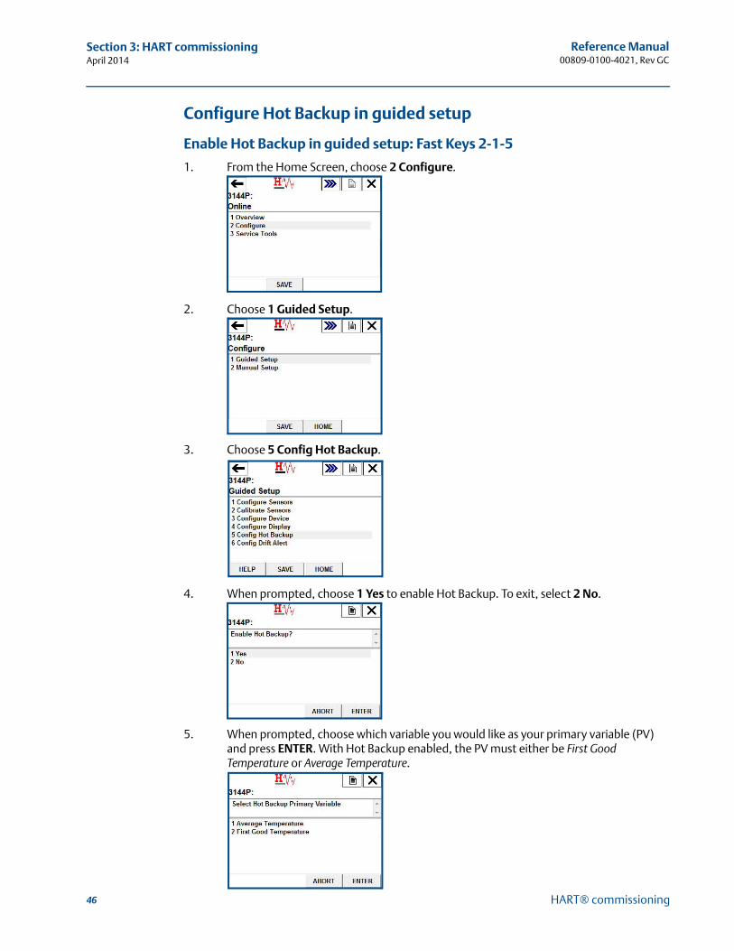
46
Reference Manual00809-0100-4021, Rev GC
Section 3: HART commissioningApril 2014
HART® commissioning
Configure Hot Backup in guided setup
Enable Hot Backup in guided setup: Fast Keys 2-1-5
1. From the Home Screen, choose 2 Configure.
2. Choose 1 Guided Setup.
3. Choose 5 Config Hot Backup.
4. When prompted, choose 1 Yes to enable Hot Backup. To exit, select 2 No.
5. When prompted, choose which variable you would like as your primary variable (PV) and press ENTER. With Hot Backup enabled, the PV must either be First Good Temperature or Average Temperature.
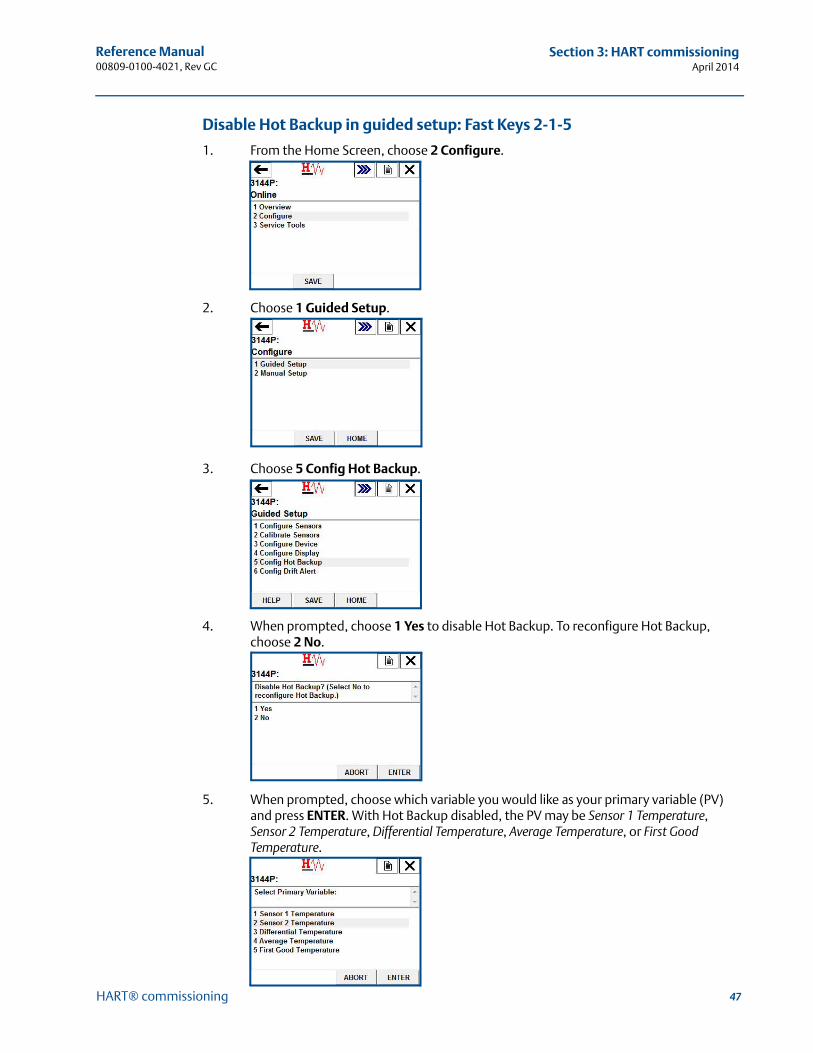
47
Reference Manual 00809-0100-4021, Rev GC
Section 3: HART commissioningApril 2014
HART® commissioning
Disable Hot Backup in guided setup: Fast Keys 2-1-5
1. From the Home Screen, choose 2 Configure.
2. Choose 1 Guided Setup.
3. Choose 5 Config Hot Backup.
4. When prompted, choose 1 Yes to disable Hot Backup. To reconfigure Hot Backup, choose 2 No.
5. When prompted, choose which variable you would like as your primary variable (PV) and press ENTER. With Hot Backup disabled, the PV may be Sensor 1 Temperature, Sensor 2 Temperature, Differential Temperature, Average Temperature, or First Good Temperature.
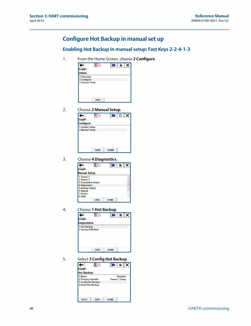
48
Reference Manual00809-0100-4021, Rev GC
Section 3: HART commissioningApril 2014
HART® commissioning
Configure Hot Backup in manual set up
Enabling Hot Backup in manual setup: Fast Keys 2-2-4-1-3
1. From the Home Screen, choose 2 Configure.
2. Choose 2 Manual Setup.
3. Choose 4 Diagnostics.
4. Choose 1 Hot Backup.
5. Select 3 Config Hot Backup.
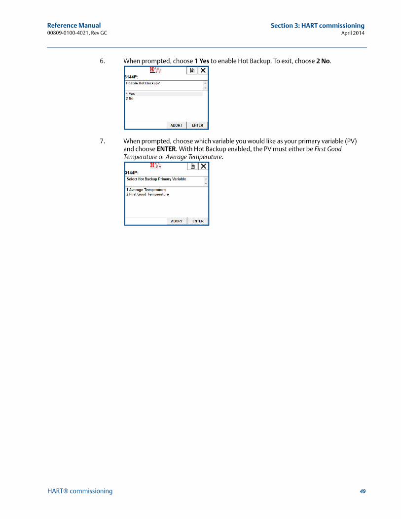
49
Reference Manual 00809-0100-4021, Rev GC
Section 3: HART commissioningApril 2014
HART® commissioning
6. When prompted, choose 1 Yes to enable Hot Backup. To exit, choose 2 No.
7. When prompted, choose which variable you would like as your primary variable (PV) and choose ENTER. With Hot Backup enabled, the PV must either be First Good Temperature or Average Temperature.
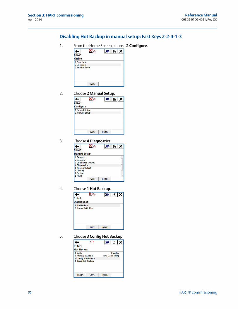
50
Reference Manual00809-0100-4021, Rev GC
Section 3: HART commissioningApril 2014
HART® commissioning
Disabling Hot Backup in manual setup: Fast Keys 2-2-4-1-3
1. From the Home Screen, choose 2 Configure.
2. Choose 2 Manual Setup.
3. Choose 4 Diagnostics.
4. Choose 1 Hot Backup.
5. Choose 3 Config Hot Backup.
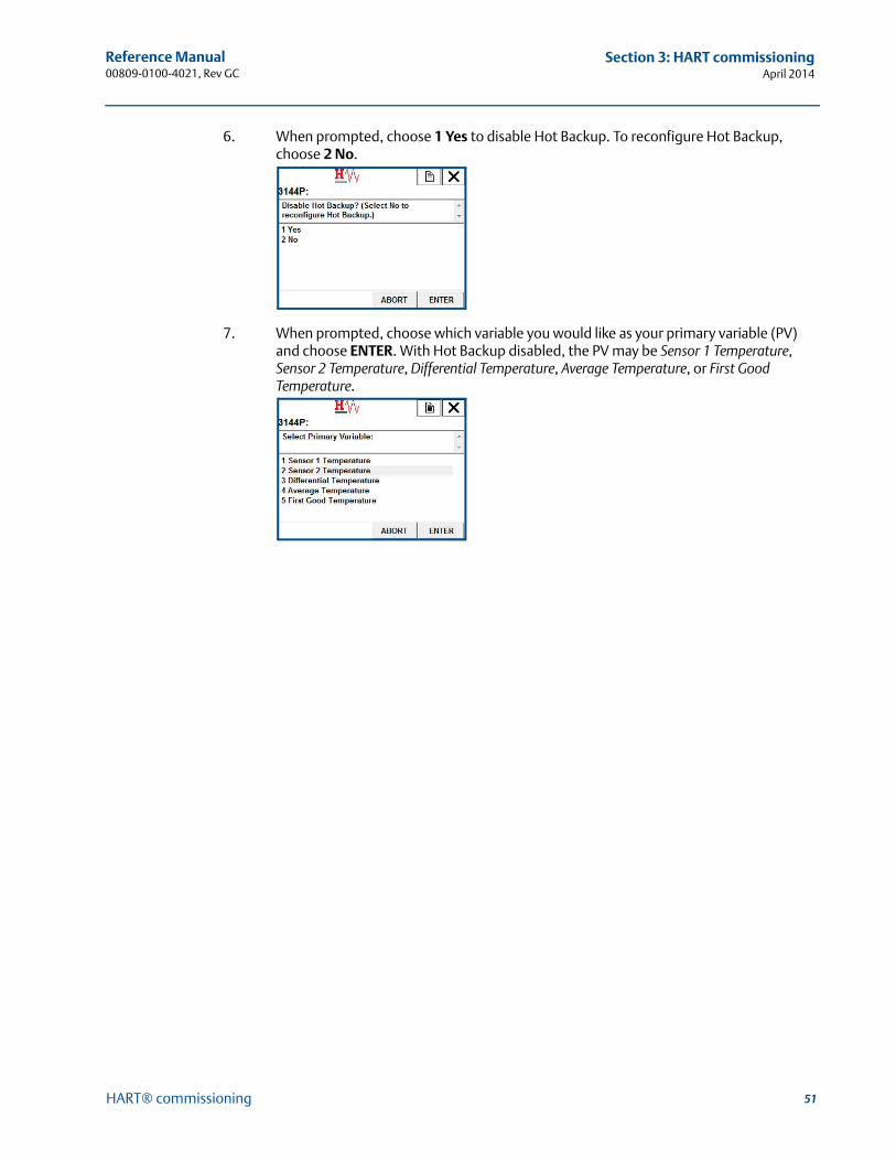
51
Reference Manual 00809-0100-4021, Rev GC
Section 3: HART commissioningApril 2014
HART® commissioning
6. When prompted, choose 1 Yes to disable Hot Backup. To reconfigure Hot Backup, choose 2 No.
7. When prompted, choose which variable you would like as your primary variable (PV) and choose ENTER. With Hot Backup disabled, the PV may be Sensor 1 Temperature, Sensor 2 Temperature, Differential Temperature, Average Temperature, or First Good Temperature.
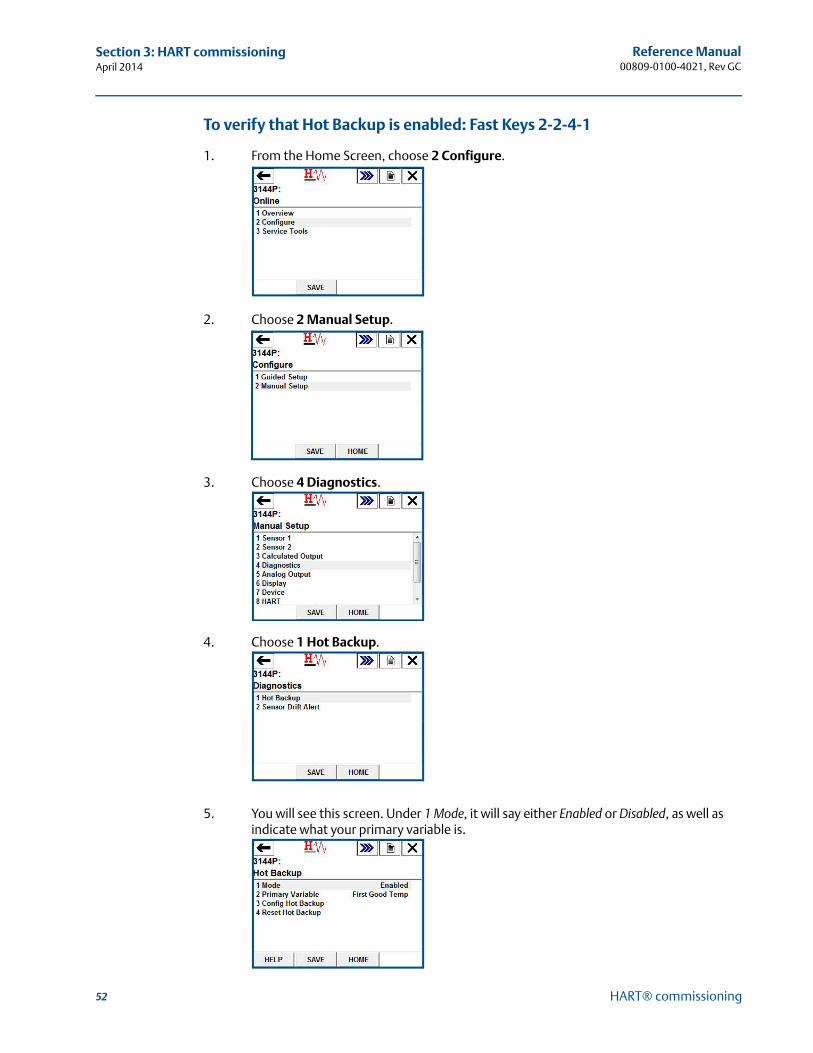
52
Reference Manual00809-0100-4021, Rev GC
Section 3: HART commissioningApril 2014
HART® commissioning
To verify that Hot Backup is enabled: Fast Keys 2-2-4-1
1. From the Home Screen, choose 2 Configure.
2. Choose 2 Manual Setup.
3. Choose 4 Diagnostics.
4. Choose 1 Hot Backup.
5. You will see this screen. Under 1 Mode, it will say either Enabled or Disabled, as well as indicate what your primary variable is.
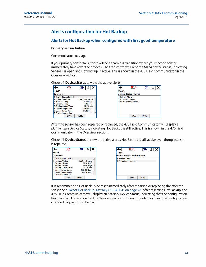
53
Reference Manual 00809-0100-4021, Rev GC
Section 3: HART commissioningApril 2014
HART® commissioning
Alerts configuration for Hot Backup
Alerts for Hot Backup when configured with first good temperature
Primary sensor failure
Communicator message
If your primary sensor fails, there will be a seamless transition where your second sensor immediately takes over the process. The transmitter will report a Failed device status, indicating Sensor 1 is open and Hot Backup is active. This is shown in the 475 Field Communicator in the Overview section.
Choose 1 Device Status to view the active alerts.
After the sensor has been repaired or replaced, the 475 Field Communicator will display a Maintenance Device Status, indicating Hot Backup is still active. This is shown in the 475 Field Communicator in the Overview section.
Choose 1 Device Status to view the active alerts. Hot Backup is still active even though sensor 1 is repaired.
It is recommended Hot Backup be reset immediately after repairing or replacing the affected sensor. See “Reset Hot Backup: Fast Keys 2-2-4-1-4” on page 78. After resetting Hot Backup, the 475 Field Communicator will display an Advisory Device Status, indicating that the configuration has changed. This is shown in the Overview section. To clear this advisory, clear the configuration changed flag, as shown below.
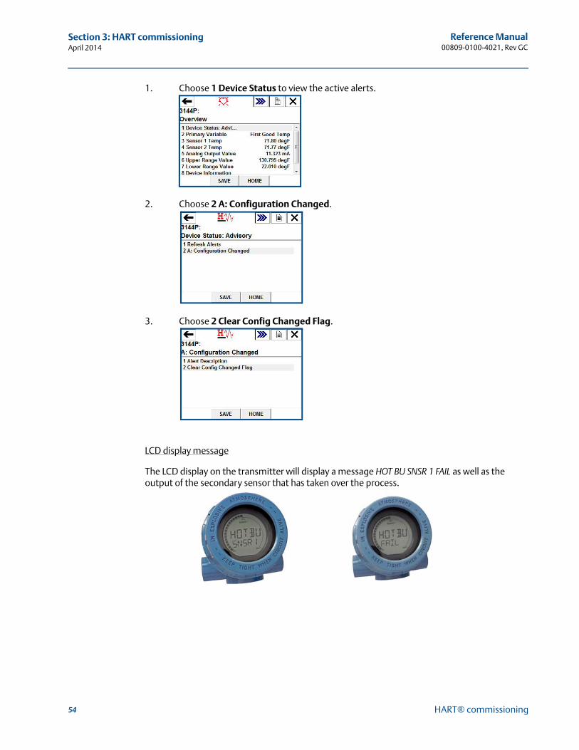
54
Reference Manual00809-0100-4021, Rev GC
Section 3: HART commissioningApril 2014
HART® commissioning
1. Choose 1 Device Status to view the active alerts.
2. Choose 2 A: Configuration Changed.
3. Choose 2 Clear Config Changed Flag.
LCD display message
The LCD display on the transmitter will display a message HOT BU SNSR 1 FAIL as well as the output of the secondary sensor that has taken over the process.
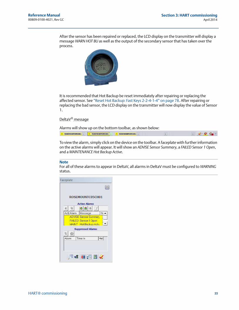
55
Reference Manual 00809-0100-4021, Rev GC
Section 3: HART commissioningApril 2014
HART® commissioning
After the sensor has been repaired or replaced, the LCD display on the transmitter will display a message WARN HOT BU as well as the output of the secondary sensor that has taken over the process.
It is recommended that Hot Backup be reset immediately after repairing or replacing the affected sensor. See “Reset Hot Backup: Fast Keys 2-2-4-1-4” on page 78. After repairing or replacing the bad sensor, the LCD display on the transmitter will now display the value of Sensor 1.
DeltaV® message
Alarms will show up on the bottom toolbar, as shown below:
To view the alarm, simply click on the device on the toolbar. A faceplate with further information on the active alarms will appear. It will show an ADVISE Sensor Summary, a FAILED Sensor 1 Open, and a MAINTENANCE Hot Backup Active.
NoteFor all of these alarms to appear in DeltaV, all alarms in DeltaV must be configured to WARNING status.
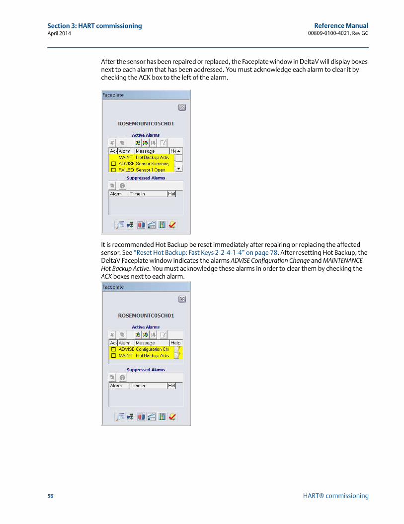
56
Reference Manual00809-0100-4021, Rev GC
Section 3: HART commissioningApril 2014
HART® commissioning
After the sensor has been repaired or replaced, the Faceplate window in DeltaV will display boxes next to each alarm that has been addressed. You must acknowledge each alarm to clear it by checking the ACK box to the left of the alarm.
It is recommended Hot Backup be reset immediately after repairing or replacing the affected sensor. See “Reset Hot Backup: Fast Keys 2-2-4-1-4” on page 78. After resetting Hot Backup, the DeltaV Faceplate window indicates the alarms ADVISE Configuration Change and MAINTENANCE Hot Backup Active. You must acknowledge these alarms in order to clear them by checking the ACK boxes next to each alarm.

57
Reference Manual 00809-0100-4021, Rev GC
Section 3: HART commissioningApril 2014
HART® commissioning
Yokogawa’s Centum PRM/DTM™ messages
When the primary sensor fails, alarms will be displayed in the PRM (Plant Resource Manager) via yellow circles next to the device, as shown below. These yellow circles indicate that something in your process needs attention. To investigate this further, right click on the affected device, and choose DTM Works… This will open the DTM (Device Task Manager).
In the DTM, the device status will indicate a Failed status in the Process Variable Overview section, shown below.
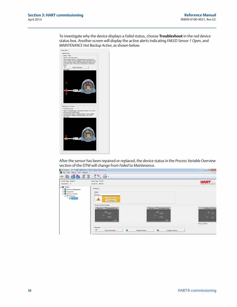
58
Reference Manual00809-0100-4021, Rev GC
Section 3: HART commissioningApril 2014
HART® commissioning
To investigate why the device displays a Failed status, choose Troubleshoot in the red device status box. Another screen will display the active alerts indicating FAILED Sensor 1 Open, and MAINTENANCE Hot Backup Active, as shown below.
After the sensor has been repaired or replaced, the device status in the Process Variable Overview section of the DTM will change from Failed to Maintenance.
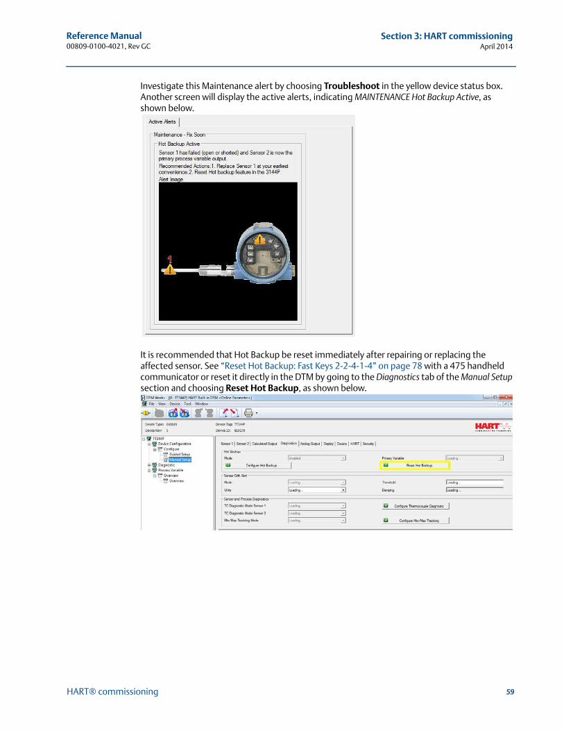
59
Reference Manual 00809-0100-4021, Rev GC
Section 3: HART commissioningApril 2014
HART® commissioning
Investigate this Maintenance alert by choosing Troubleshoot in the yellow device status box. Another screen will display the active alerts, indicating MAINTENANCE Hot Backup Active, as shown below.
It is recommended that Hot Backup be reset immediately after repairing or replacing the affected sensor. See “Reset Hot Backup: Fast Keys 2-2-4-1-4” on page 78 with a 475 handheld communicator or reset it directly in the DTM by going to the Diagnostics tab of the Manual Setup section and choosing Reset Hot Backup, as shown below.
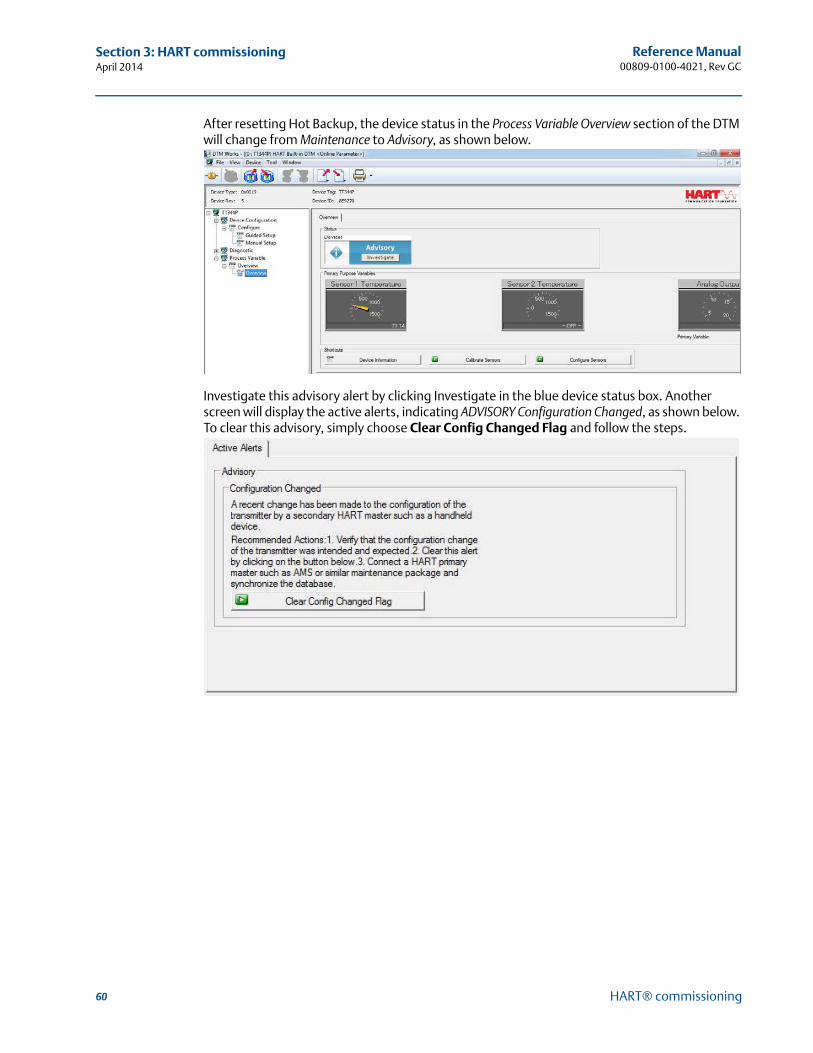
60
Reference Manual00809-0100-4021, Rev GC
Section 3: HART commissioningApril 2014
HART® commissioning
After resetting Hot Backup, the device status in the Process Variable Overview section of the DTM will change from Maintenance to Advisory, as shown below.
Investigate this advisory alert by clicking Investigate in the blue device status box. Another screen will display the active alerts, indicating ADVISORY Configuration Changed, as shown below. To clear this advisory, simply choose Clear Config Changed Flag and follow the steps.
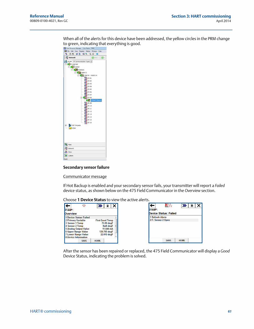
61
Reference Manual 00809-0100-4021, Rev GC
Section 3: HART commissioningApril 2014
HART® commissioning
When all of the alerts for this device have been addressed, the yellow circles in the PRM change to green, indicating that everything is good.
Secondary sensor failure
Communicator message
If Hot Backup is enabled and your secondary sensor fails, your transmitter will report a Failed device status, as shown below on the 475 Field Communicator in the Overview section.
Choose 1 Device Status to view the active alerts.
After the sensor has been repaired or replaced, the 475 Field Communicator will display a Good Device Status, indicating the problem is solved.
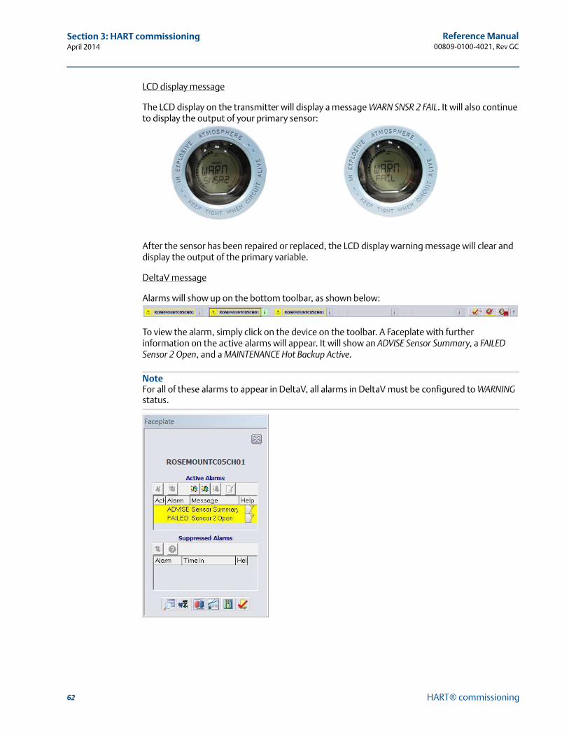
62
Reference Manual00809-0100-4021, Rev GC
Section 3: HART commissioningApril 2014
HART® commissioning
LCD display message
The LCD display on the transmitter will display a message WARN SNSR 2 FAIL. It will also continue to display the output of your primary sensor:
After the sensor has been repaired or replaced, the LCD display warning message will clear and display the output of the primary variable.
DeltaV message
Alarms will show up on the bottom toolbar, as shown below:
To view the alarm, simply click on the device on the toolbar. A Faceplate with further information on the active alarms will appear. It will show an ADVISE Sensor Summary, a FAILED Sensor 2 Open, and a MAINTENANCE Hot Backup Active.
NoteFor all of these alarms to appear in DeltaV, all alarms in DeltaV must be configured to WARNING status.
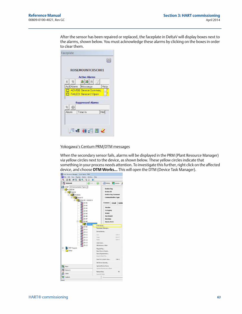
63
Reference Manual 00809-0100-4021, Rev GC
Section 3: HART commissioningApril 2014
HART® commissioning
After the sensor has been repaired or replaced, the faceplate in DeltaV will display boxes next to the alarms, shown below. You must acknowledge these alarms by clicking on the boxes in order to clear them.
Yokogawa’s Centum PRM/DTM messages
When the secondary sensor fails, alarms will be displayed in the PRM (Plant Resource Manager) via yellow circles next to the device, as shown below. These yellow circles indicate that something in your process needs attention. To investigate this further, right click on the affected device, and choose DTM Works… This will open the DTM (Device Task Manager).
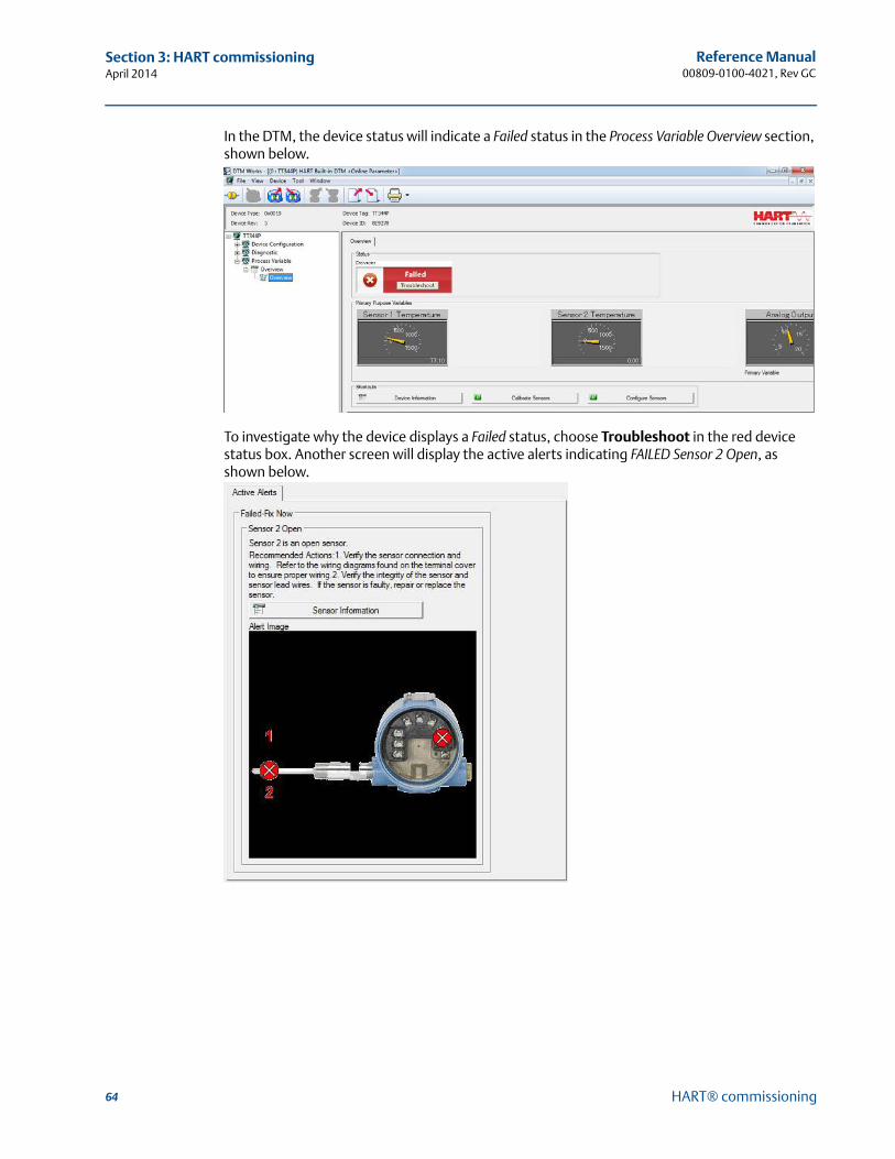
64
Reference Manual00809-0100-4021, Rev GC
Section 3: HART commissioningApril 2014
HART® commissioning
In the DTM, the device status will indicate a Failed status in the Process Variable Overview section, shown below.
To investigate why the device displays a Failed status, choose Troubleshoot in the red device status box. Another screen will display the active alerts indicating FAILED Sensor 2 Open, as shown below.
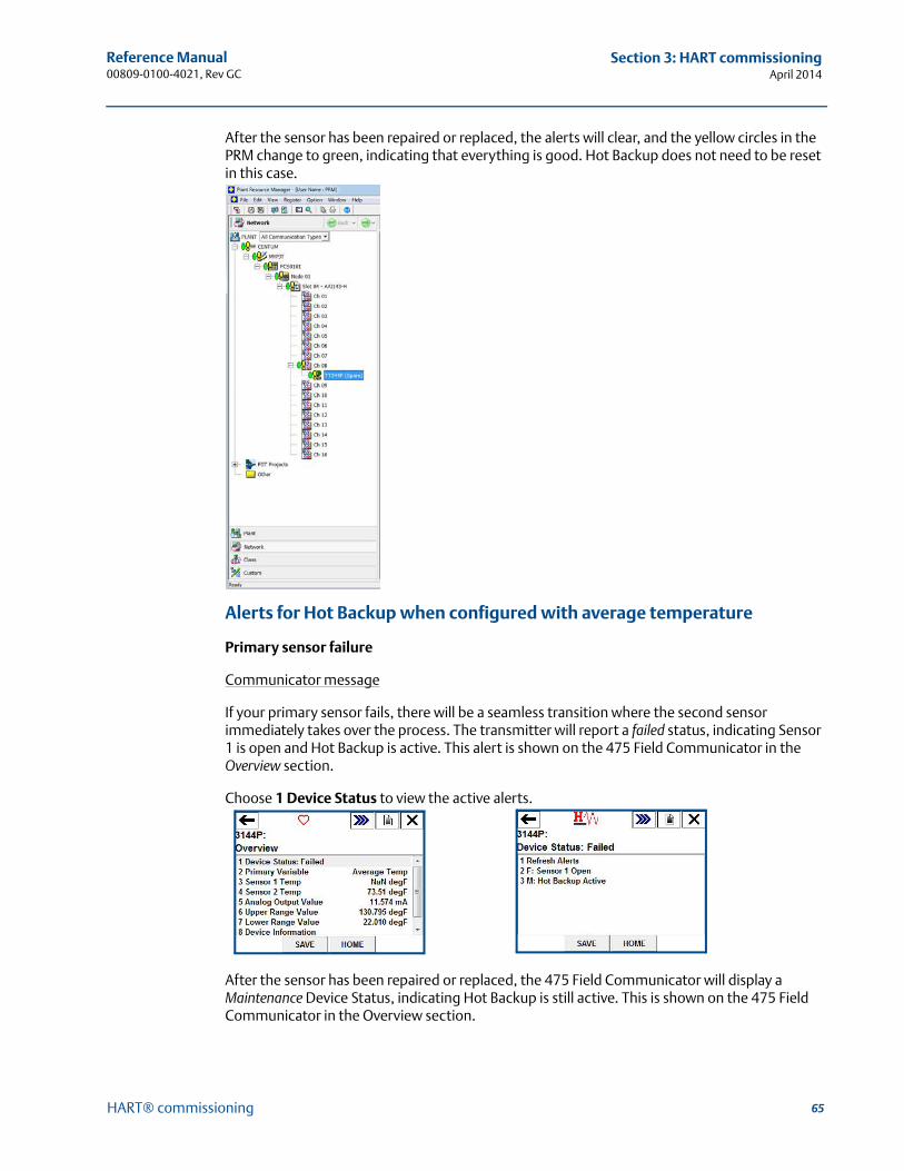
65
Reference Manual 00809-0100-4021, Rev GC
Section 3: HART commissioningApril 2014
HART® commissioning
After the sensor has been repaired or replaced, the alerts will clear, and the yellow circles in the PRM change to green, indicating that everything is good. Hot Backup does not need to be reset in this case.
Alerts for Hot Backup when configured with average temperature
Primary sensor failure
Communicator message
If your primary sensor fails, there will be a seamless transition where the second sensor immediately takes over the process. The transmitter will report a failed status, indicating Sensor 1 is open and Hot Backup is active. This alert is shown on the 475 Field Communicator in the Overview section.
Choose 1 Device Status to view the active alerts.
After the sensor has been repaired or replaced, the 475 Field Communicator will display a Maintenance Device Status, indicating Hot Backup is still active. This is shown on the 475 Field Communicator in the Overview section.
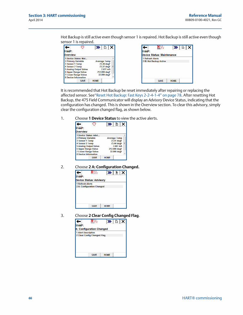
66
Reference Manual00809-0100-4021, Rev GC
Section 3: HART commissioningApril 2014
HART® commissioning
Hot Backup is still active even though sensor 1 is repaired. Hot Backup is still active even though sensor 1 is repaired.
It is recommended that Hot Backup be reset immediately after repairing or replacing the affected sensor. See“Reset Hot Backup: Fast Keys 2-2-4-1-4” on page 78. After resetting Hot Backup, the 475 Field Communicator will display an Advisory Device Status, indicating that the configuration has changed. This is shown in the Overview section. To clear this advisory, simply clear the configuration changed flag, as shown below.
1. Choose 1 Device Status to view the active alerts.
2. Choose 2 A: Configuration Changed.
3. Choose 2 Clear Config Changed Flag.
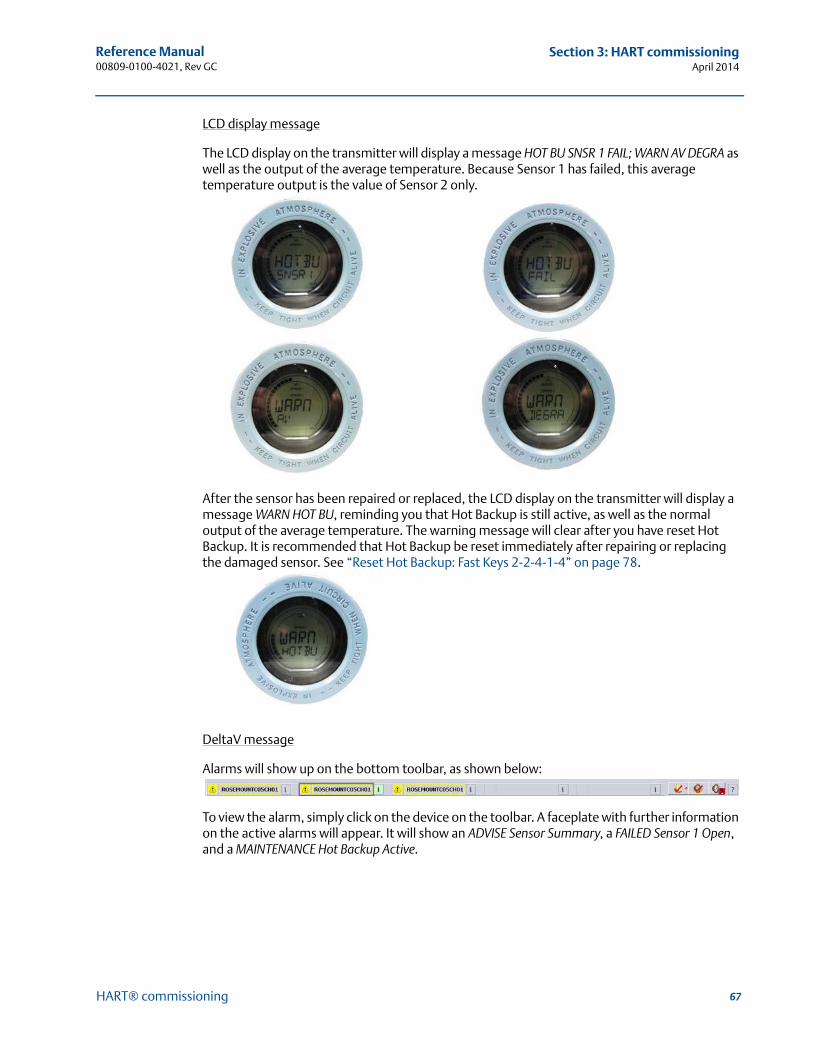
67
Reference Manual 00809-0100-4021, Rev GC
Section 3: HART commissioningApril 2014
HART® commissioning
LCD display message
The LCD display on the transmitter will display a message HOT BU SNSR 1 FAIL; WARN AV DEGRA as well as the output of the average temperature. Because Sensor 1 has failed, this average temperature output is the value of Sensor 2 only.
After the sensor has been repaired or replaced, the LCD display on the transmitter will display a message WARN HOT BU, reminding you that Hot Backup is still active, as well as the normal output of the average temperature. The warning message will clear after you have reset Hot Backup. It is recommended that Hot Backup be reset immediately after repairing or replacing the damaged sensor. See “Reset Hot Backup: Fast Keys 2-2-4-1-4” on page 78.
DeltaV message
Alarms will show up on the bottom toolbar, as shown below:
To view the alarm, simply click on the device on the toolbar. A faceplate with further information on the active alarms will appear. It will show an ADVISE Sensor Summary, a FAILED Sensor 1 Open, and a MAINTENANCE Hot Backup Active.
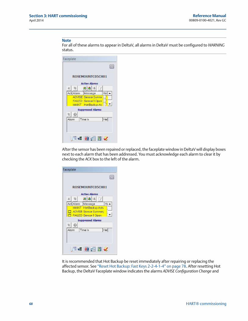
68
Reference Manual00809-0100-4021, Rev GC
Section 3: HART commissioningApril 2014
HART® commissioning
NoteFor all of these alarms to appear in DeltaV, all alarms in DeltaV must be configured to WARNING status.
After the sensor has been repaired or replaced, the faceplate window in DeltaV will display boxes next to each alarm that has been addressed. You must acknowledge each alarm to clear it by checking the ACK box to the left of the alarm.
It is recommended that Hot Backup be reset immediately after repairing or replacing the affected sensor. See “Reset Hot Backup: Fast Keys 2-2-4-1-4” on page 78. After resetting Hot Backup, the DeltaV Faceplate window indicates the alarms ADVISE Configuration Change and
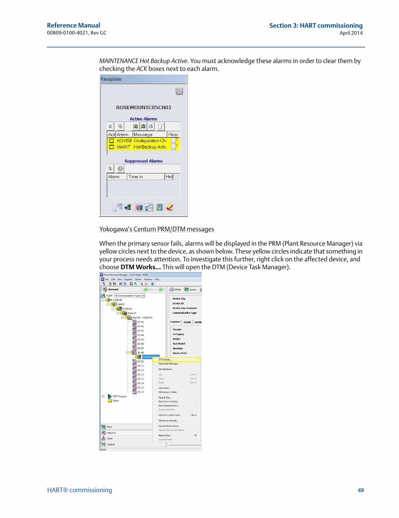
69
Reference Manual 00809-0100-4021, Rev GC
Section 3: HART commissioningApril 2014
HART® commissioning
MAINTENANCE Hot Backup Active. You must acknowledge these alarms in order to clear them by checking the ACK boxes next to each alarm.
Yokogawa’s Centum PRM/DTM messages
When the primary sensor fails, alarms will be displayed in the PRM (Plant Resource Manager) via yellow circles next to the device, as shown below. These yellow circles indicate that something in your process needs attention. To investigate this further, right click on the affected device, and choose DTM Works… This will open the DTM (Device Task Manager).
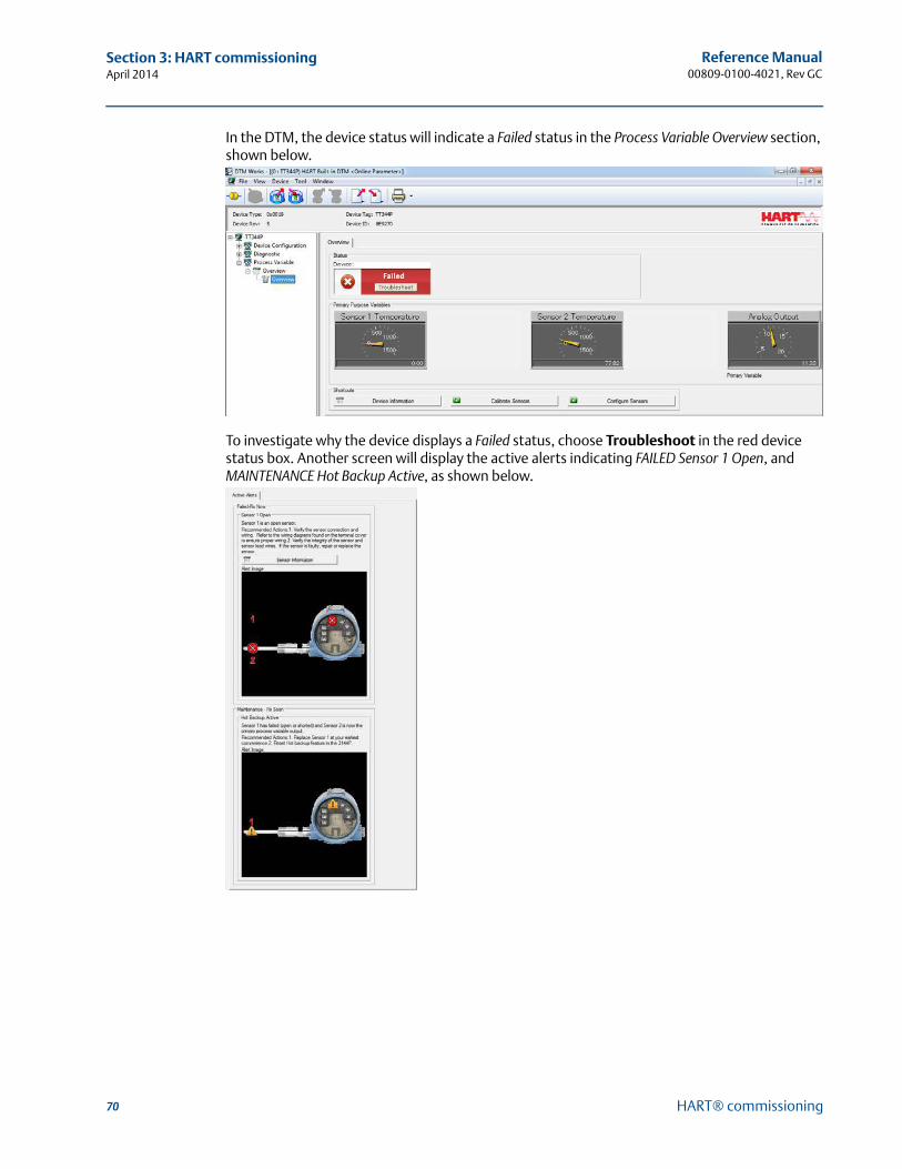
70
Reference Manual00809-0100-4021, Rev GC
Section 3: HART commissioningApril 2014
HART® commissioning
In the DTM, the device status will indicate a Failed status in the Process Variable Overview section, shown below.
To investigate why the device displays a Failed status, choose Troubleshoot in the red device status box. Another screen will display the active alerts indicating FAILED Sensor 1 Open, and MAINTENANCE Hot Backup Active, as shown below.
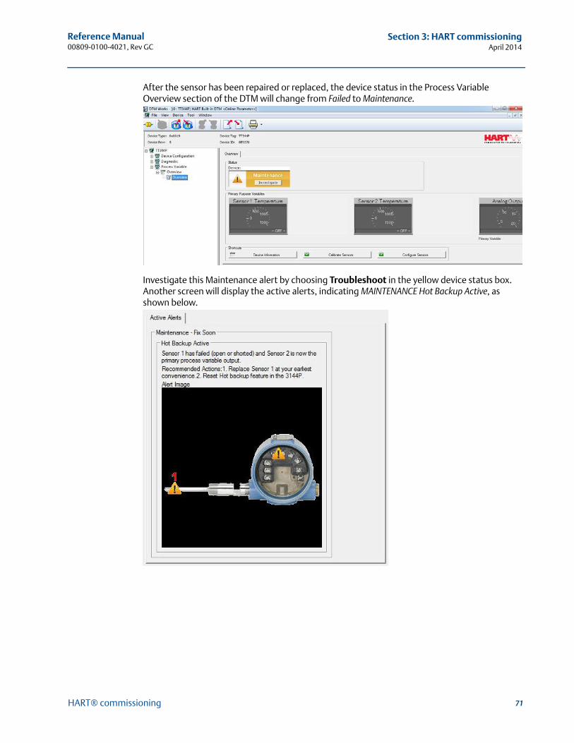
71
Reference Manual 00809-0100-4021, Rev GC
Section 3: HART commissioningApril 2014
HART® commissioning
After the sensor has been repaired or replaced, the device status in the Process Variable Overview section of the DTM will change from Failed to Maintenance.
Investigate this Maintenance alert by choosing Troubleshoot in the yellow device status box. Another screen will display the active alerts, indicating MAINTENANCE Hot Backup Active, as shown below.
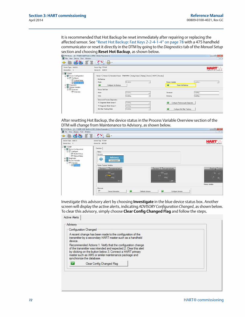
72
Reference Manual00809-0100-4021, Rev GC
Section 3: HART commissioningApril 2014
HART® commissioning
It is recommended that Hot Backup be reset immediately after repairing or replacing the affected sensor. See “Reset Hot Backup: Fast Keys 2-2-4-1-4” on page 78 with a 475 handheld communicator or reset it directly in the DTM by going to the Diagnostics tab of the Manual Setup section and choosing Reset Hot Backup, as shown below.
After resetting Hot Backup, the device status in the Process Variable Overview section of the DTM will change from Maintenance to Advisory, as shown below.
Investigate this advisory alert by choosing Investigate in the blue device status box. Another screen will display the active alerts, indicating ADVISORY Configuration Changed, as shown below. To clear this advisory, simply choose Clear Config Changed Flag and follow the steps.

73
Reference Manual 00809-0100-4021, Rev GC
Section 3: HART commissioningApril 2014
HART® commissioning
When all of the alerts for this device have been addressed, the yellow circles in the PRM change to green, indicating that everything is good.
Secondary sensor failure
Communicator message
If Hot Backup is enabled and your secondary sensor fails, your transmitter will report a Failed device status. The alerts show that Sensor 2 is open, but Hot Backup is not active, as shown below on the 475 Field Communicator in the Overview section:
Choose 1 Device Status to view the active alerts.
After the sensor has been repaired or replaced, the 475 Field Communicator will display a Good Device Status, indicating the problem is solved.
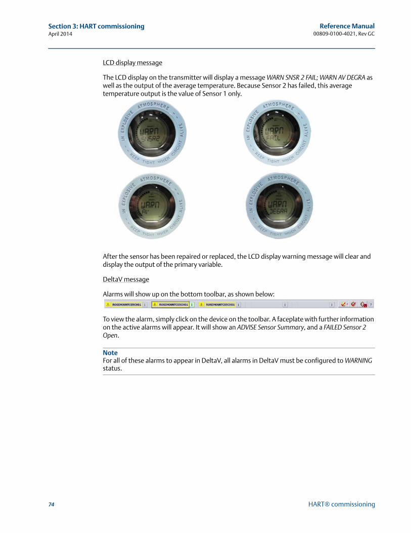
74
Reference Manual00809-0100-4021, Rev GC
Section 3: HART commissioningApril 2014
HART® commissioning
LCD display message
The LCD display on the transmitter will display a message WARN SNSR 2 FAIL; WARN AV DEGRA as well as the output of the average temperature. Because Sensor 2 has failed, this average temperature output is the value of Sensor 1 only.
After the sensor has been repaired or replaced, the LCD display warning message will clear and display the output of the primary variable.
DeltaV message
Alarms will show up on the bottom toolbar, as shown below:
To view the alarm, simply click on the device on the toolbar. A faceplate with further information on the active alarms will appear. It will show an ADVISE Sensor Summary, and a FAILED Sensor 2 Open.
NoteFor all of these alarms to appear in DeltaV, all alarms in DeltaV must be configured to WARNING status.

75
Reference Manual 00809-0100-4021, Rev GC
Section 3: HART commissioningApril 2014
HART® commissioning
After the sensor has been repaired or replaced, the faceplate in DeltaV will display boxes next to the alarms, shown below. You must acknowledge these alarms by clicking on the boxes in order to clear them.
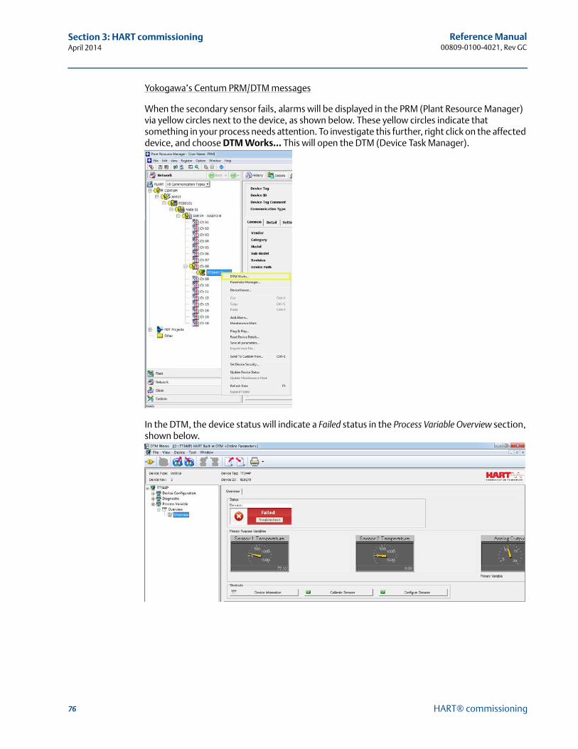
76
Reference Manual00809-0100-4021, Rev GC
Section 3: HART commissioningApril 2014
HART® commissioning
Yokogawa’s Centum PRM/DTM messages
When the secondary sensor fails, alarms will be displayed in the PRM (Plant Resource Manager) via yellow circles next to the device, as shown below. These yellow circles indicate that something in your process needs attention. To investigate this further, right click on the affected device, and choose DTM Works… This will open the DTM (Device Task Manager).
In the DTM, the device status will indicate a Failed status in the Process Variable Overview section, shown below.
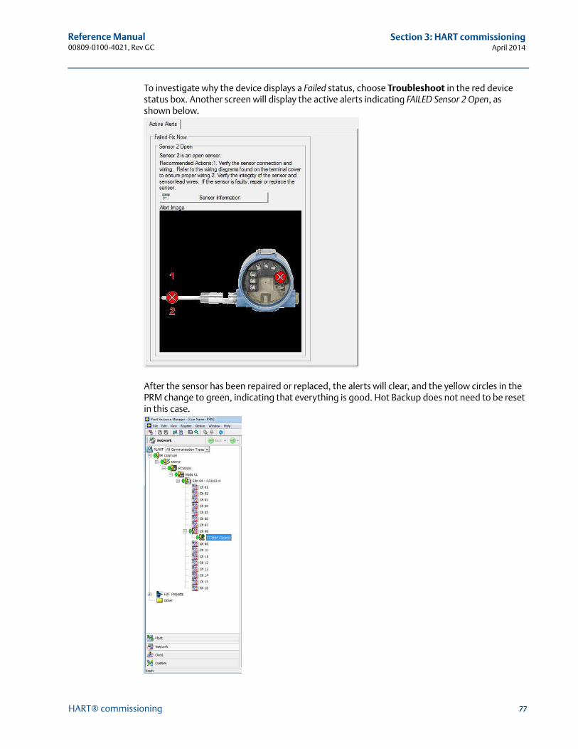
77
Reference Manual 00809-0100-4021, Rev GC
Section 3: HART commissioningApril 2014
HART® commissioning
To investigate why the device displays a Failed status, choose Troubleshoot in the red device status box. Another screen will display the active alerts indicating FAILED Sensor 2 Open, as shown below.
After the sensor has been repaired or replaced, the alerts will clear, and the yellow circles in the PRM change to green, indicating that everything is good. Hot Backup does not need to be reset in this case.
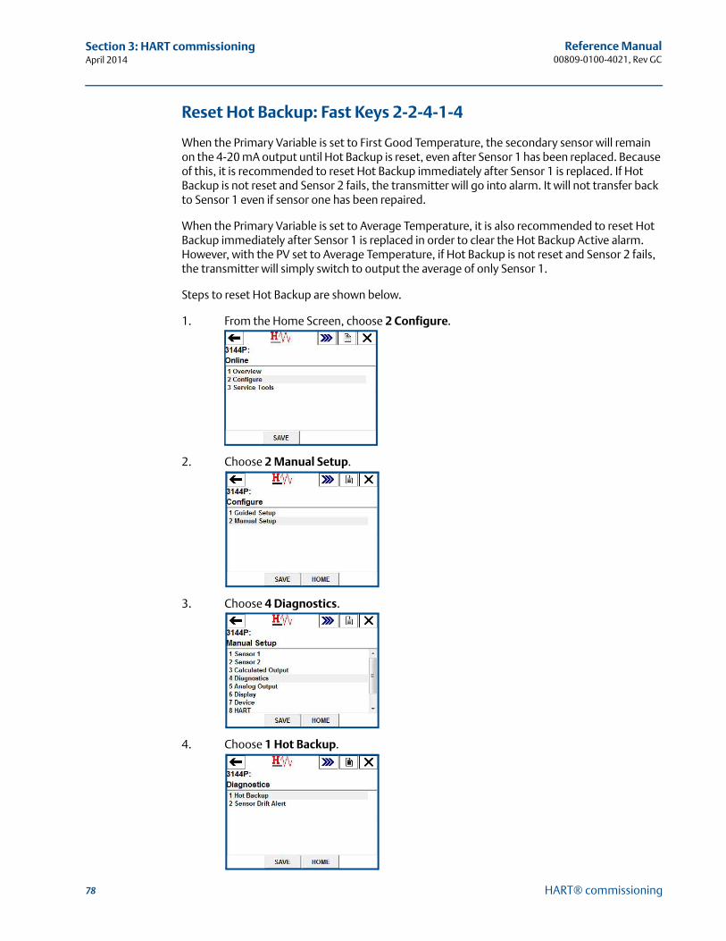
78
Reference Manual00809-0100-4021, Rev GC
Section 3: HART commissioningApril 2014
HART® commissioning
Reset Hot Backup: Fast Keys 2-2-4-1-4
When the Primary Variable is set to First Good Temperature, the secondary sensor will remain on the 4-20 mA output until Hot Backup is reset, even after Sensor 1 has been replaced. Because of this, it is recommended to reset Hot Backup immediately after Sensor 1 is replaced. If Hot Backup is not reset and Sensor 2 fails, the transmitter will go into alarm. It will not transfer back to Sensor 1 even if sensor one has been repaired.
When the Primary Variable is set to Average Temperature, it is also recommended to reset Hot Backup immediately after Sensor 1 is replaced in order to clear the Hot Backup Active alarm. However, with the PV set to Average Temperature, if Hot Backup is not reset and Sensor 2 fails, the transmitter will simply switch to output the average of only Sensor 1.
Steps to reset Hot Backup are shown below.
1. From the Home Screen, choose 2 Configure.
2. Choose 2 Manual Setup.
3. Choose 4 Diagnostics.
4. Choose 1 Hot Backup.
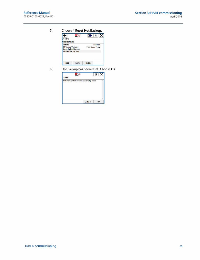
79
Reference Manual 00809-0100-4021, Rev GC
Section 3: HART commissioningApril 2014
HART® commissioning
5. Choose 4 Reset Hot Backup.
6. Hot Backup has been reset. Choose OK.
80
Reference Manual00809-0100-4021, Rev GC
Section 3: HART commissioningApril 2014
HART® commissioning
Sensor drift alert configuration
Field communicator
The Sensor Drift Alert command allows the transmitter to set a warning flag (through HART), or go into analog alarm when the temperature difference between Sensor 1 and Sensor 2 exceeds a user-defined limit. This feature is useful when measuring the same process temperature with two sensors, ideally when using a dual-element sensor. When Sensor Drift Alert mode is enabled, the user sets the maximum allowable difference, in engineering units, between Sensor 1 and Sensor 2. If this maximum difference is exceeded, a Sensor Drift Alert warning flag will be set.
When configuring the transmitter for Sensor Drift Alert, the user also has the option of specifying that the analog output of the transmitter go into alarm when sensor drifting is detected.
NoteUsing dual sensor configuration in the 3144P, the temperature transmitter supports the configuration and simultaneous use of the Hot Backup® feature and Sensor Drift Alert. If one sensor fails, the transmitter switches output to use the remaining good sensor. Should the difference between the two sensor readings exceed the configured threshold, the AO will go to alarm indicating the sensor drift condition. The combination of Sensor Drift Alert and the Hot Backup® feature improves sensor diagnostic coverage while maintaining a high level of availability. Refer to the 3144P FMEDA report for the impact on safety.
Problem description: Sensors often drift before they fail. This causes issues because during the drift period, the sensor is not reporting as accurate measurement. In control loops, and especially safety loops this can lead to improper process control and potential safety hazards.
Our solution: The Sensor Drift Alert continuously monitors two sensor readings to detect a drifting sensor. The diagnostic monitors the difference between the two sensors, and when the difference becomes greater than a value entered by the user, the transmitter sends an alert to indicate a sensor drift condition.
How it works: Two sensors are connected to a dual-input transmitter where the difference in sensor readings is continuously being measured. A threshold is set by the user to determine when an excessive drift (i.e. a significant delta) occurs between the two sensors. The temperature delta between the two sensors is calculated by taking the absolute value of the difference between sensor 1 and sensor 2. The user configures the transmitter to send a digital alert or analog alarm when the alert has been triggered. The Sensor Drift Alert does not indicate which sensor is failing. Rather the diagnostic provides an indication of a sensor drifting. The user should view the individual sensor output trends on the host to determine which sensor is drifting.
Take away: “Sensor Drift Alert detects a degrading sensor.”
Target applications: Redundant measurements, critical measurements, severe applications.
HART 5 Fast Keys 2, 2, 4, 2
HART 7 Fast Keys 2, 2, 4, 2
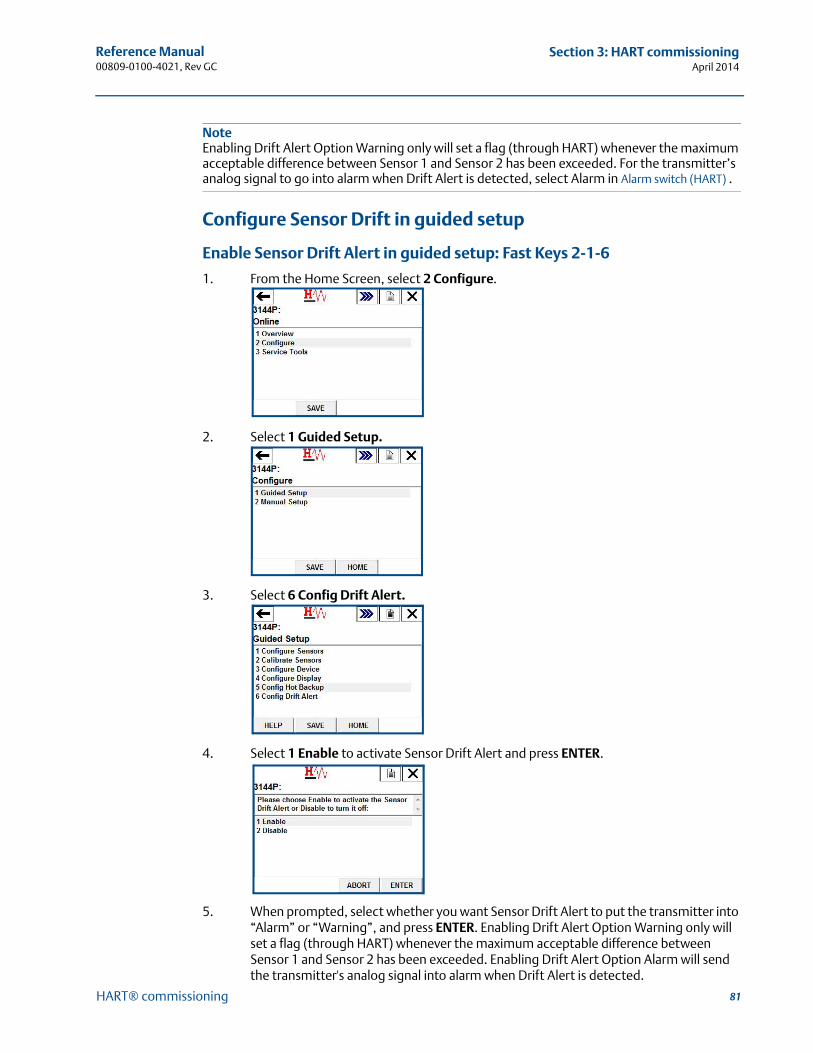
81
Reference Manual 00809-0100-4021, Rev GC
Section 3: HART commissioningApril 2014
HART® commissioning
NoteEnabling Drift Alert Option Warning only will set a flag (through HART) whenever the maximum acceptable difference between Sensor 1 and Sensor 2 has been exceeded. For the transmitter’s analog signal to go into alarm when Drift Alert is detected, select Alarm in Alarm switch (HART) .
Configure Sensor Drift in guided setup
Enable Sensor Drift Alert in guided setup: Fast Keys 2-1-6
1. From the Home Screen, select 2 Configure.
2. Select 1 Guided Setup.
3. Select 6 Config Drift Alert.
4. Select 1 Enable to activate Sensor Drift Alert and press ENTER.
5. When prompted, select whether you want Sensor Drift Alert to put the transmitter into “Alarm” or “Warning”, and press ENTER. Enabling Drift Alert Option Warning only will set a flag (through HART) whenever the maximum acceptable difference between Sensor 1 and Sensor 2 has been exceeded. Enabling Drift Alert Option Alarm will send the transmitter's analog signal into alarm when Drift Alert is detected.
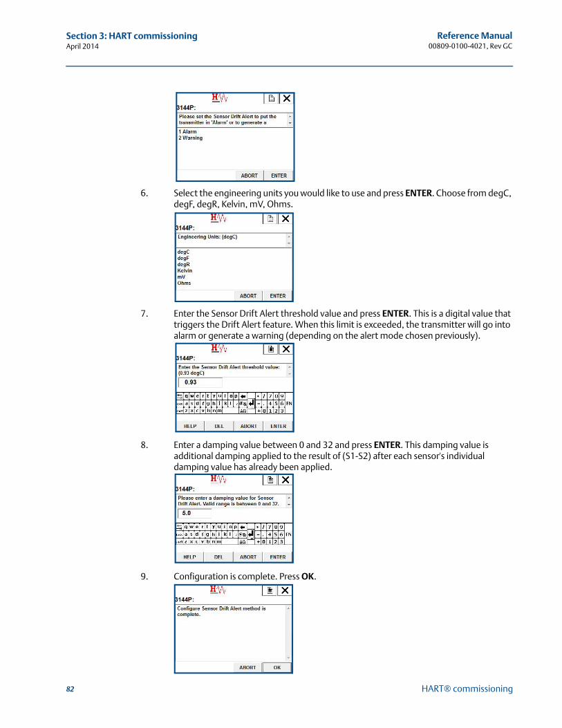
82
Reference Manual00809-0100-4021, Rev GC
Section 3: HART commissioningApril 2014
HART® commissioning
6. Select the engineering units you would like to use and press ENTER. Choose from degC, degF, degR, Kelvin, mV, Ohms.
7. Enter the Sensor Drift Alert threshold value and press ENTER. This is a digital value that triggers the Drift Alert feature. When this limit is exceeded, the transmitter will go into alarm or generate a warning (depending on the alert mode chosen previously).
8. Enter a damping value between 0 and 32 and press ENTER. This damping value is additional damping applied to the result of (S1-S2) after each sensor's individual damping value has already been applied.
9. Configuration is complete. Press OK.
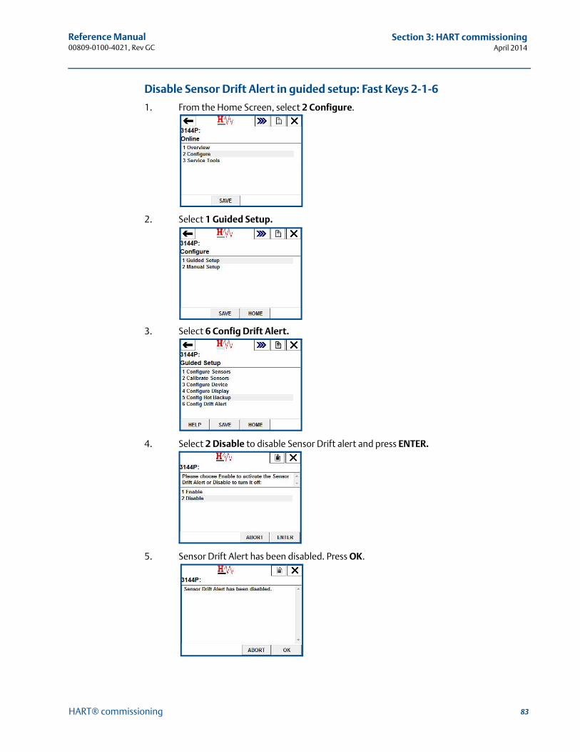
83
Reference Manual 00809-0100-4021, Rev GC
Section 3: HART commissioningApril 2014
HART® commissioning
Disable Sensor Drift Alert in guided setup: Fast Keys 2-1-6
1. From the Home Screen, select 2 Configure.
2. Select 1 Guided Setup.
3. Select 6 Config Drift Alert.
4. Select 2 Disable to disable Sensor Drift alert and press ENTER.
5. Sensor Drift Alert has been disabled. Press OK.
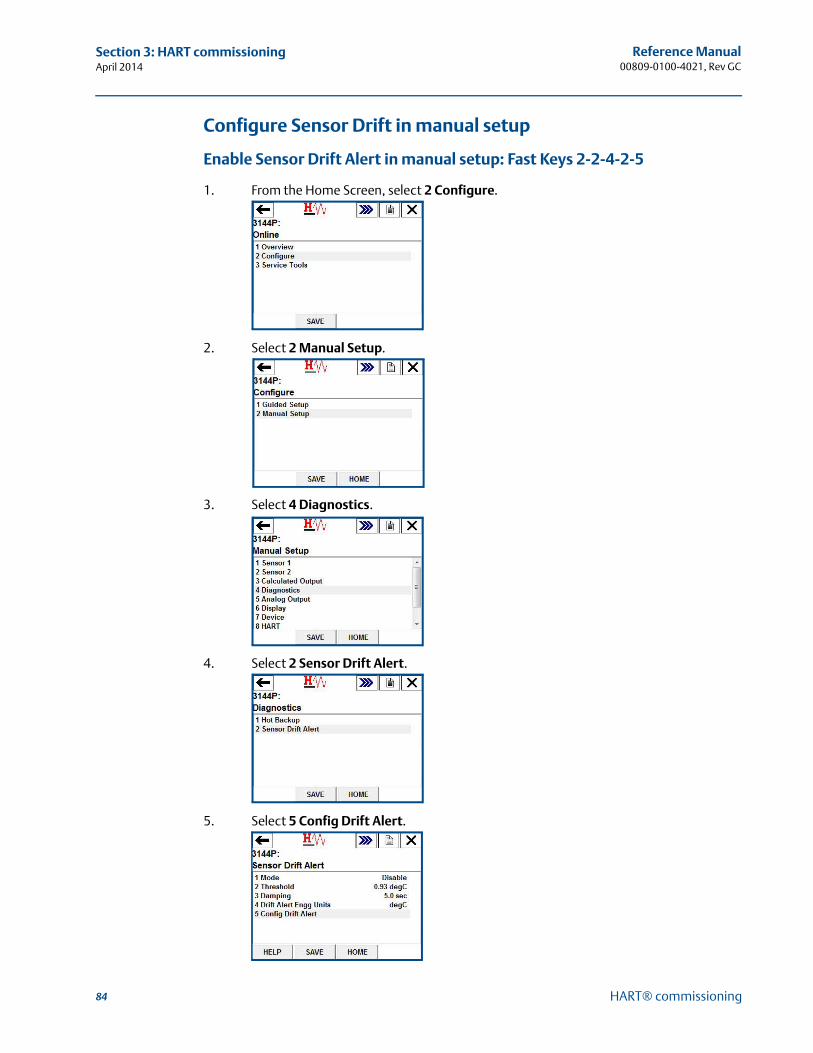
84
Reference Manual00809-0100-4021, Rev GC
Section 3: HART commissioningApril 2014
HART® commissioning
Configure Sensor Drift in manual setup
Enable Sensor Drift Alert in manual setup: Fast Keys 2-2-4-2-5
1. From the Home Screen, select 2 Configure.
2. Select 2 Manual Setup.
3. Select 4 Diagnostics.
4. Select 2 Sensor Drift Alert.
5. Select 5 Config Drift Alert.
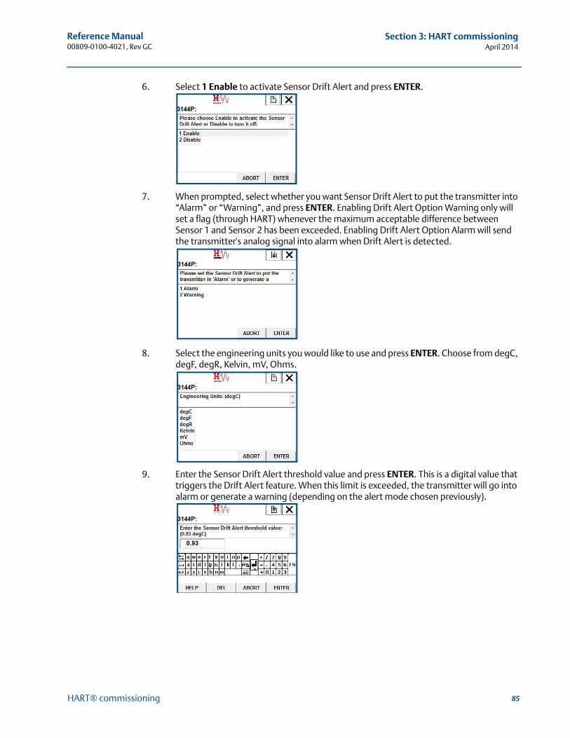
85
Reference Manual 00809-0100-4021, Rev GC
Section 3: HART commissioningApril 2014
HART® commissioning
6. Select 1 Enable to activate Sensor Drift Alert and press ENTER.
7. When prompted, select whether you want Sensor Drift Alert to put the transmitter into “Alarm” or “Warning”, and press ENTER. Enabling Drift Alert Option Warning only will set a flag (through HART) whenever the maximum acceptable difference between Sensor 1 and Sensor 2 has been exceeded. Enabling Drift Alert Option Alarm will send the transmitter's analog signal into alarm when Drift Alert is detected.
8. Select the engineering units you would like to use and press ENTER. Choose from degC, degF, degR, Kelvin, mV, Ohms.
9. Enter the Sensor Drift Alert threshold value and press ENTER. This is a digital value that triggers the Drift Alert feature. When this limit is exceeded, the transmitter will go into alarm or generate a warning (depending on the alert mode chosen previously).
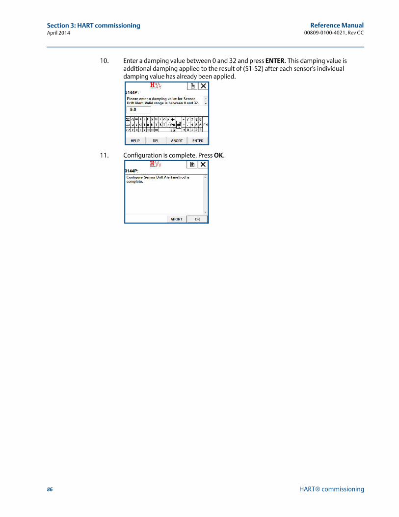
86
Reference Manual00809-0100-4021, Rev GC
Section 3: HART commissioningApril 2014
HART® commissioning
10. Enter a damping value between 0 and 32 and press ENTER. This damping value is additional damping applied to the result of (S1-S2) after each sensor's individual damping value has already been applied.
11. Configuration is complete. Press OK.

87
Reference Manual 00809-0100-4021, Rev GC
Section 3: HART commissioningApril 2014
HART® commissioning
Disable Sensor Drift Alert in manual setup: Fast Keys 2-2-4-2-5
1. From the Home Screen, select 2 Configure.
2. Select 2 Manual Setup.
3. Select 4 Diagnostics.
4. Select 2 Sensor Drift Alert.
5. Select 5 Config Drift Alert.
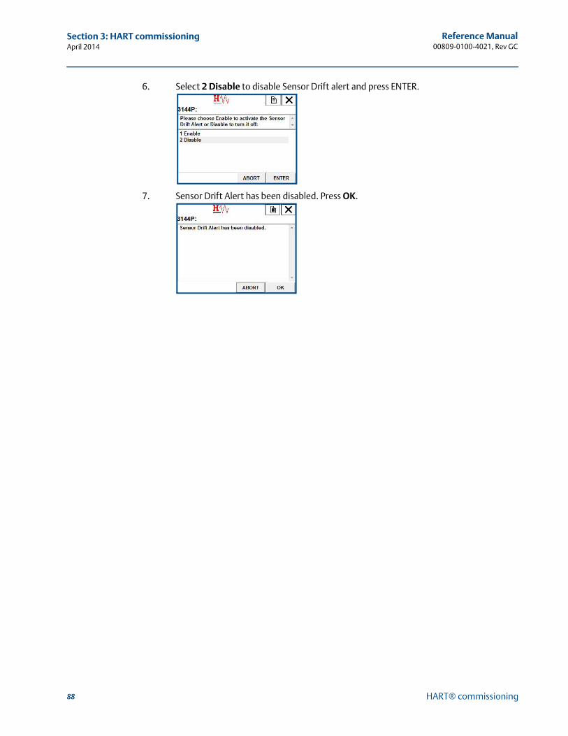
88
Reference Manual00809-0100-4021, Rev GC
Section 3: HART commissioningApril 2014
HART® commissioning
6. Select 2 Disable to disable Sensor Drift alert and press ENTER.
7. Sensor Drift Alert has been disabled. Press OK.
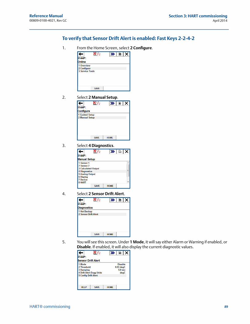
89
Reference Manual 00809-0100-4021, Rev GC
Section 3: HART commissioningApril 2014
HART® commissioning
To verify that Sensor Drift Alert is enabled: Fast Keys 2-2-4-2
1. From the Home Screen, select 2 Configure.
2. Select 2 Manual Setup.
3. Select 4 Diagnostics.
4. Select 2 Sensor Drift Alert.
5. You will see this screen. Under 1 Mode, it will say either Alarm or Warning if enabled, or Disable. If enabled, it will also display the current diagnostic values.
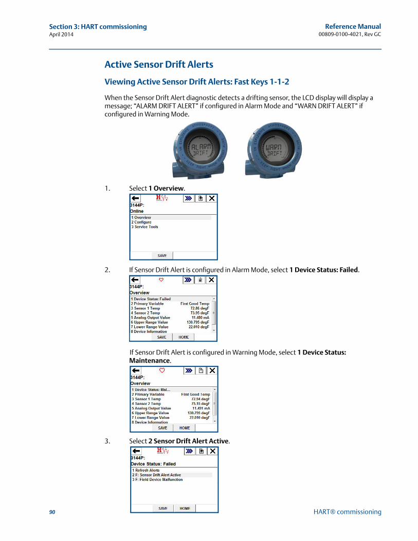
90
Reference Manual00809-0100-4021, Rev GC
Section 3: HART commissioningApril 2014
HART® commissioning
Active Sensor Drift Alerts
Viewing Active Sensor Drift Alerts: Fast Keys 1-1-2
When the Sensor Drift Alert diagnostic detects a drifting sensor, the LCD display will display a message; “ALARM DRIFT ALERT” if configured in Alarm Mode and “WARN DRIFT ALERT” if configured in Warning Mode.
1. Select 1 Overview.
2. If Sensor Drift Alert is configured in Alarm Mode, select 1 Device Status: Failed.
If Sensor Drift Alert is configured in Warning Mode, select 1 Device Status: Maintenance.
3. Select 2 Sensor Drift Alert Active.
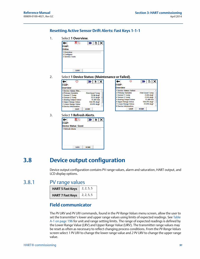
91
Reference Manual 00809-0100-4021, Rev GC
Section 3: HART commissioningApril 2014
HART® commissioning
Resetting Active Sensor Drift Alerts: Fast Keys 1-1-1
1. Select 1 Overview.
2. Select 1 Device Status: (Maintenance or Failed).
3. Select 1 Refresh Alerts.
3.8 Device output configuration
Device output configuration contains PV range values, alarm and saturation, HART output, and LCD display options.
3.8.1 PV range values
Field communicator
The PV URV and PV LRV commands, found in the PV Range Values menu screen, allow the user to set the transmitter’s lower and upper range values using limits of expected readings. See Table A-1 on page 196 for unit and range setting limits. The range of expected readings is defined by the Lower Range Value (LRV) and Upper Range Value (URV). The transmitter range values may be reset as often as necessary to reflect changing process conditions. From the PV Range Values screen select 1 PV LRV to change the lower range value and 2 PV URV to change the upper range value.
HART 5 Fast Keys 2, 2, 5, 5
HART 7 Fast Keys 2, 2, 5, 5
92
Reference Manual00809-0100-4021, Rev GC
Section 3: HART commissioningApril 2014
HART® commissioning
Reranging the transmitter sets the measurement range to the limits of the expected readings, which maximizes transmitter performance; the transmitter is most accurate when operated within the expected temperature range for the application.
The re-range functions should not be confused with the trim function. Although re-ranging the transmitter matches a sensor input to a 4-20 mA output, as in conventional calibration, it does not affect the transmitter’s interpretation of the input.
3.8.2 Process variable damping
Field communicator
The PV Damp command changes the response time of the transmitter to smooth variations in output readings caused by rapid changes in input. Determine the appropriate damping setting based on the necessary response time, signal stability, and other requirements of the loop dynamics of the system. The default damping value is 5.0 seconds and can be reset to any value between 1 and 32 seconds.
The value chosen for damping affects the response time of the transmitter. When set to zero (disabled), the damping function is off and the transmitter output reacts to changes in input as quickly as the intermittent sensor algorithm allows. Increasing the damping value increases transmitter response time.
Damping
Damping values may be used for, and should equal, the update rate for Sensor 1, Sensor 2, and sensor differential. Sensor configuration automatically calculates a damping value. The default damping value is 5 seconds. Damping may be disabled by setting the parameter damping value to 0 seconds. The maximum damping value allowed is 32 seconds.
An alternate damping value may be entered with the following restrictions:
1. Single Sensor Configuration:
50 Hz or 60 Hz Line Voltage Filters have a minimum user-configurable damping value of 0.5 seconds
2. Dual Sensor Configuration:
50 Hz Line Voltage Filter a minimum user-configurable damping value of 0.9 seconds
60 Hz Line Voltage Filter a minimum user-configurable damping value of 0.7 seconds
HART 5 Fast KeysSensor 1: 2, 2, 1, 6Sensor 2: 2, 2, 2, 6
HART 7 Fast KeysSensor 1: 2, 2, 1, 7Sensor 1: 2, 2, 2, 7
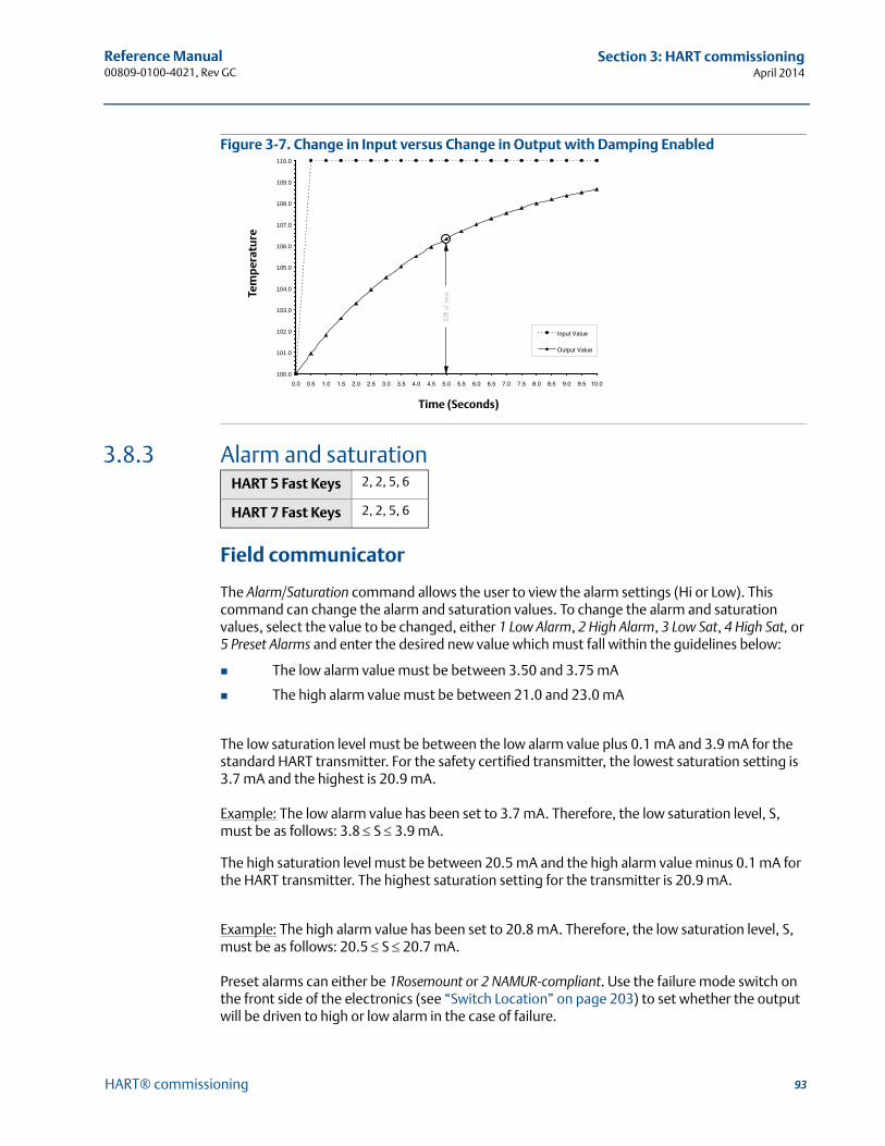
93
Reference Manual 00809-0100-4021, Rev GC
Section 3: HART commissioningApril 2014
HART® commissioning
Figure 3-7. Change in Input versus Change in Output with Damping Enabled
3.8.3 Alarm and saturation
Field communicator
The Alarm/Saturation command allows the user to view the alarm settings (Hi or Low). This command can change the alarm and saturation values. To change the alarm and saturation values, select the value to be changed, either 1 Low Alarm, 2 High Alarm, 3 Low Sat, 4 High Sat, or 5 Preset Alarms and enter the desired new value which must fall within the guidelines below:
The low alarm value must be between 3.50 and 3.75 mA
The high alarm value must be between 21.0 and 23.0 mA
The low saturation level must be between the low alarm value plus 0.1 mA and 3.9 mA for the standard HART transmitter. For the safety certified transmitter, the lowest saturation setting is 3.7 mA and the highest is 20.9 mA.
Example: The low alarm value has been set to 3.7 mA. Therefore, the low saturation level, S, must be as follows: 3.8 S 3.9 mA.
The high saturation level must be between 20.5 mA and the high alarm value minus 0.1 mA for the HART transmitter. The highest saturation setting for the transmitter is 20.9 mA.
Example: The high alarm value has been set to 20.8 mA. Therefore, the low saturation level, S, must be as follows: 20.5 S 20.7 mA.
Preset alarms can either be 1Rosemount or 2 NAMUR-compliant. Use the failure mode switch on the front side of the electronics (see “Switch Location” on page 203) to set whether the output will be driven to high or low alarm in the case of failure.
HART 5 Fast Keys 2, 2, 5, 6
HART 7 Fast Keys 2, 2, 5, 6
100.0
101.0
102.0
103.0
104.0
105.0
106.0
107.0
108.0
109.0
110.0
0.0 0.5 1.0 1.5 2.0 2.5 3.0 3.5 4.0 4.5 5.0 5.5 6.0 6.5 7.0 7.5 8.0 8.5 9.0 9.5 10.0
Input Value
Output Value
Time (Seconds)
Tem
per
atu
re
94
Reference Manual00809-0100-4021, Rev GC
Section 3: HART commissioningApril 2014
HART® commissioning
3.8.4 HART output
The HART Output command allows the user to make changes to the multidrop address, initiate burst mode, or make changes to the burst options.
3.8.5 LCD display options
The LCD Display Option command sets the meter options, including engineering units and decimal point. Change the LCD display settings to reflect necessary configuration parameters when adding a LCD display or reconfiguring the transmitter. Transmitters without LCD displays are shipped with the meter configuration set to “Not Used.”
3.9 Device information
Access the transmitter information variables online using the Field Communicator or other suitable communications device. The following is a list of transmitter information variables, including device identifiers, factory-set configuration variables, and other information. A description of each variable, the corresponding fast key sequence, and a review are provided.
3.9.1 Tag
The Tag variable is the easiest way to identify and distinguish between transmitters in multi-transmitter environments. It is used to label transmitters electronically according to the requirements of the application. The defined tag is automatically displayed when a HART-based communicator establishes contact with the transmitter at power-up. The tag may be up to eight characters long and has no impact on the primary variable readings of the transmitter.
3.9.2 Long tag
Long Tag is similar to Tag. The long tag is different in that the Long tag can be up to 32 Characters instead of the 8 characters in traditional Tag.
HART 5 Fast Keys 2, 2, 8
HART 7 Fast Keys 2, 2, 8
HART 5 Fast Keys 2, 2, 6
HART 7 Fast Keys 2, 2, 6
HART 5 Fast Keys 2, 2, 7, 1, 1
HART 7 Fast Keys 2, 2, 7, 1, 1
HART 5 Fast Keys HART 7 Only
HART 7 Fast Keys 2, 2, 7, 1, 2
95
Reference Manual 00809-0100-4021, Rev GC
Section 3: HART commissioningApril 2014
HART® commissioning
3.9.3 Date
The Date command is a user-defined variable that provides a place to save the date of the last revision of configuration information. It has no impact on the operation of the transmitter or the HART-based communicator.
3.9.4 Descriptor
The Descriptor variable provides a longer user-defined electronic label to assist with more specific transmitter identification than is available with tag. The descriptor may be up to 16 characters long and has no impact on the operation of the transmitter or the HART-based communicator.
3.9.5 Message
The Message variable provides the most specific user-defined means for identifying individual transmitters in multi-transmitter environments. It allows for 32 characters of information and is stored with the other configuration data. The message variable has no impact on the operation of the transmitter or the HART-based communicator.
3.10 Measurement filtering
3.10.1 50/60 Hz filter
The 50/60 Hz Filter (also known as Line Voltage Filter or AC Power Filter) command sets the transmitter electronic filter to reject the frequency of the AC power supply in the plant. The 60 Hz or 50 Hz mode can be chosen. The factory default for this setting is 60 Hz.
NoteIn high noise environments, normal mode is recommended.
HART 5 Fast Keys 2, 2, 7, 1, 2
HART 7 Fast Keys 2, 2, 7, 1, 3
HART 5 Fast Keys 2, 2, 7, 1, 3
HART 7 Fast Keys 2, 2, 7, 1, 4
HART 5 Fast Keys 2, 2, 7, 1, 4
HART 7 Fast Keys 2, 2, 7, 1, 5
HART 5 Fast Keys 2, 2, 7, 5, 1
HART 7 Fast Keys 2, 2, 7, 5, 1
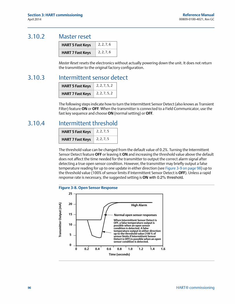
96
Reference Manual00809-0100-4021, Rev GC
Section 3: HART commissioningApril 2014
HART® commissioning
3.10.2 Master reset
Master Reset resets the electronics without actually powering down the unit. It does not return the transmitter to the original factory configuration.
3.10.3 Intermittent sensor detect
The following steps indicate how to turn the Intermittent Sensor Detect (also knows as Transient Filter) feature ON or OFF. When the transmitter is connected to a Field Communicator, use the fast key sequence and choose ON (normal setting) or OFF.
3.10.4 Intermittent threshold
The threshold value can be changed from the default value of 0.2%. Turning the Intermittent Sensor Detect feature OFF or leaving it ON and increasing the threshold value above the default does not affect the time needed for the transmitter to output the correct alarm signal after detecting a true open sensor condition. However, the transmitter may briefly output a false temperature reading for up to one update in either direction (see Figure 3-9 on page 98) up to the threshold value (100% of sensor limits if Intermittent Sensor Detect is OFF). Unless a rapid response rate is necessary, the suggested setting is ON with 0.2% threshold.
Figure 3-8. Open Sensor Response
HART 5 Fast Keys 2, 2, 7, 6
HART 7 Fast Keys 2, 2, 7, 6
HART 5 Fast Keys 2, 2, 7, 5, 2
HART 7 Fast Keys 2, 2, 7, 5, 2
HART 5 Fast Keys 2, 2, 7, 5
HART 7 Fast Keys 2, 2, 7, 5
00
5
10
15
20
25
0.2 0.4 0.6 0.8 1.0 1.2 1.4 1.6
Tran
smit
ter
Ou
tpu
t (m
A)
Time (seconds)
When Intermittent Sensor Detect is OFF, a false temperature output is possible when an open sensor condition is detected. A false temperature output in either direction up to the threshold value (100 % of sensor limits if Intermittent Sensor Detect is OFF) is possible when an open sensor condition is detected.
Normal open sensor responses
High Alarm
97
Reference Manual 00809-0100-4021, Rev GC
Section 3: HART commissioningApril 2014
HART® commissioning
Intermittent Sensor Detect (advanced feature)
The Intermittent Sensor Detect feature is designed to guard against process temperature readings caused by intermittent open sensor conditions. An intermittent sensor condition is an open sensor condition that lasts less than one update. By default, the transmitter is shipped with the Intermittent Sensor Detect feature switched ON and the threshold value set at 0.2% of sensor limits. The Intermittent Sensor Detect feature can be switched ON or OFF and the threshold value can be changed to any value between 0 and 100% of the sensor limits with a Field Communicator.
Transmitter behavior with Intermittent Sensor Detect ON
When the Intermittent Sensor Detect feature is switched ON, the transmitter can eliminate the output pulse caused by intermittent open sensor conditions. Process temperature changes (T) within the threshold value will be tracked normally by the transmitter’s output. A T greater than the threshold value will activate the intermittent sensor algorithm. True open sensor conditions will cause the transmitter to go into alarm.
The threshold value of the 3144P should be set at a level that allows the normal range of process temperature fluctuations; too high and the algorithm will not be able to filter out intermittent conditions; too low and the algorithm will be activated unnecessarily. The default threshold value is 0.2% of the sensor limits.
Transmitter behavior with Intermittent Sensor Detect OFF
When the Intermittent Sensor Detect feature is switched OFF, the transmitter tracks all process temperature changes, even from an intermittent sensor. (The transmitter in effect behaves as though the threshold value had been set at 100%.) The output delay due to the intermittent sensor algorithm will be eliminated.
3.10.5 Open sensor holdoff
The Open Sensor Holdoff option, at the normal setting, enables the 3144P to be more robust under heavy EMI conditions. This is accomplished by the software having the transmitter perform additional verification of the open sensor status prior to activating the transmitter alarm. If the additional verification shows that the open sensor condition is not valid, the transmitter will not go into alarm.
For users of the 3144P that desire a more vigorous open sensor detection, the Open Sensor Holdoff option can be changed to a fast setting where the transmitter will report an open sensor condition without additional verification of the open condition.
3.11 Diagnostics and service
Diagnostics and service functions listed below are primarily for use after field installation. The Transmitter Test feature is designed to verify that the transmitter is operating properly, and can be performed either on the bench or in the field. The Loop Test feature is designed to verify proper loop wiring and transmitter output, and should only be performed after you install the transmitter.
HART 5 Fast Keys 2, 2, 7, 4
HART 7 Fast Keys 2, 2, 7, 4
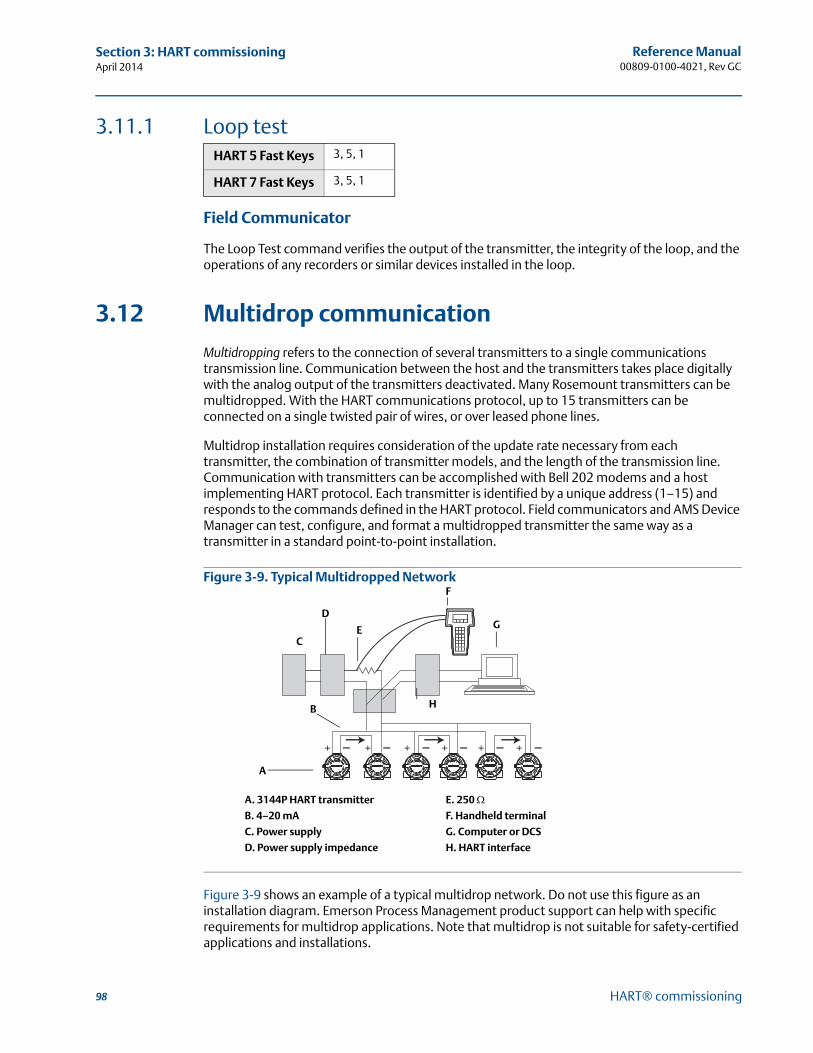
98
Reference Manual00809-0100-4021, Rev GC
Section 3: HART commissioningApril 2014
HART® commissioning
3.11.1 Loop test
Field Communicator
The Loop Test command verifies the output of the transmitter, the integrity of the loop, and the operations of any recorders or similar devices installed in the loop.
3.12 Multidrop communication
Multidropping refers to the connection of several transmitters to a single communications transmission line. Communication between the host and the transmitters takes place digitally with the analog output of the transmitters deactivated. Many Rosemount transmitters can be multidropped. With the HART communications protocol, up to 15 transmitters can be connected on a single twisted pair of wires, or over leased phone lines.
Multidrop installation requires consideration of the update rate necessary from each transmitter, the combination of transmitter models, and the length of the transmission line. Communication with transmitters can be accomplished with Bell 202 modems and a host implementing HART protocol. Each transmitter is identified by a unique address (1–15) and responds to the commands defined in the HART protocol. Field communicators and AMS Device Manager can test, configure, and format a multidropped transmitter the same way as a transmitter in a standard point-to-point installation.
Figure 3-9. Typical Multidropped Network
Figure 3-9 shows an example of a typical multidrop network. Do not use this figure as an installation diagram. Emerson Process Management product support can help with specific requirements for multidrop applications. Note that multidrop is not suitable for safety-certified applications and installations.
HART 5 Fast Keys 3, 5, 1
HART 7 Fast Keys 3, 5, 1
A. 3144P HART transmitter E. 250 B. 4–20 mA F. Handheld terminal
C. Power supply G. Computer or DCS
D. Power supply impedance H. HART interface
C
D
F
G
A
B H
E

99
Reference Manual 00809-0100-4021, Rev GC
Section 3: HART commissioningApril 2014
HART® commissioning
A HART-based communicator can test, configure, and format a multidropped 3144P transmitter the same as in a standard point-to-point installation.
NoteThe 3144P is set to address 0 at the factory, allowing it to operate in the standard point-to-point manner with a 4–20 mA output signal. To activate multidrop communication, the transmitter address must be changed to a number between 1 and 15, which deactivates the 4–20 mA analog output, sending it to a fixed 4 mA output. The failure mode current is also disabled. It also disables the failure mode alarm signal, which is controlled by the upscale/downscale switch/jumper position. Failure signals in multidropped transmitters are communicated through HART messages.
3.13 Use with the HART Tri-Loop
To prepare the 3144P transmitter with dual-sensor option for use with a Rosemount 333 HART Tri-Loop, the transmitter must be configured to Burst Mode and the process variable output order must be set. In Burst Mode, the transmitter provides digital information for the four process variables to the HART Tri-Loop. The HART Tri-Loop divides the signal into separate 4–20 mA loops for up to three of the following choices:
primary variable (PV)
secondary variable (SV)
tertiary variable (TV)
quaternary variable (QV)
When using the 3144P transmitter with dual-sensor option in conjunction with the HART Tri-Loop, consider the configuration of the differential, average, first good temperatures, Sensor Drift Alert, and the Hot Backup feature (if applicable).
NoteThe procedures are to be used when the sensors and transmitters are connected, powered, and functioning properly. Also, a field communicator must be connected and communicating to the transmitter control loop. For communicator usage instructions, see “Commissioning” on page 10.
Set the transmitter to Burst Mode
Set process variable output order
NoteTake careful note of the process variable output order. The HART Tri-Loop must be configured to read the variables in the same order.
HART 5 Fast Keys 2, 2, 8, 4
HART 7 Fast Keys 2, 2, 8, 4
HART 5 Fast Keys 2, 2, 8, 5
HART 7 Fast Keys 2, 2, 8, 5
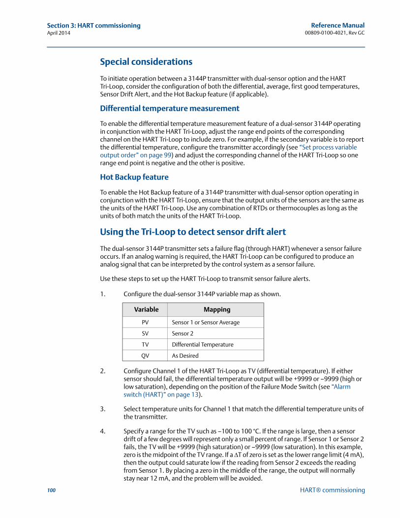
100
Reference Manual00809-0100-4021, Rev GC
Section 3: HART commissioningApril 2014
HART® commissioning
Special considerations
To initiate operation between a 3144P transmitter with dual-sensor option and the HART Tri-Loop, consider the configuration of both the differential, average, first good temperatures, Sensor Drift Alert, and the Hot Backup feature (if applicable).
Differential temperature measurement
To enable the differential temperature measurement feature of a dual-sensor 3144P operating in conjunction with the HART Tri-Loop, adjust the range end points of the corresponding channel on the HART Tri-Loop to include zero. For example, if the secondary variable is to report the differential temperature, configure the transmitter accordingly (see “Set process variable output order” on page 99) and adjust the corresponding channel of the HART Tri-Loop so one range end point is negative and the other is positive.
Hot Backup feature
To enable the Hot Backup feature of a 3144P transmitter with dual-sensor option operating in conjunction with the HART Tri-Loop, ensure that the output units of the sensors are the same as the units of the HART Tri-Loop. Use any combination of RTDs or thermocouples as long as the units of both match the units of the HART Tri-Loop.
Using the Tri-Loop to detect sensor drift alert
The dual-sensor 3144P transmitter sets a failure flag (through HART) whenever a sensor failure occurs. If an analog warning is required, the HART Tri-Loop can be configured to produce an analog signal that can be interpreted by the control system as a sensor failure.
Use these steps to set up the HART Tri-Loop to transmit sensor failure alerts.
1. Configure the dual-sensor 3144P variable map as shown.
2. Configure Channel 1 of the HART Tri-Loop as TV (differential temperature). If either sensor should fail, the differential temperature output will be +9999 or –9999 (high or low saturation), depending on the position of the Failure Mode Switch (see “Alarm switch (HART)” on page 13).
3. Select temperature units for Channel 1 that match the differential temperature units of the transmitter.
4. Specify a range for the TV such as –100 to 100 °C. If the range is large, then a sensor drift of a few degrees will represent only a small percent of range. If Sensor 1 or Sensor 2 fails, the TV will be +9999 (high saturation) or –9999 (low saturation). In this example, zero is the midpoint of the TV range. If a T of zero is set as the lower range limit (4 mA), then the output could saturate low if the reading from Sensor 2 exceeds the reading from Sensor 1. By placing a zero in the middle of the range, the output will normally stay near 12 mA, and the problem will be avoided.
Variable Mapping
PV Sensor 1 or Sensor Average
SV Sensor 2
TV Differential Temperature
QV As Desired
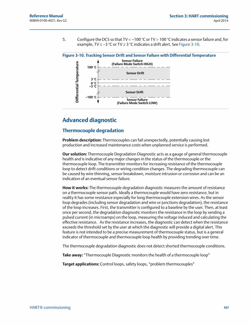
101
Reference Manual 00809-0100-4021, Rev GC
Section 3: HART commissioningApril 2014
HART® commissioning
5. Configure the DCS so that TV –100 °C or TV 100 °C indicates a sensor failure and, for example, TV –3 °C or TV 3 °C indicates a drift alert. See Figure 3-10.
Figure 3-10. Tracking Sensor Drift and Sensor Failure with Differential Temperature
Advanced diagnostic
Thermocouple degradation
Problem description: Thermocouples can fail unexpectedly, potentially causing lost production and increased maintenance costs when unplanned service is performed.
Our solution: Thermocouple Degradation Diagnostic acts as a gauge of general thermocouple health and is indicative of any major changes in the status of the thermocouple or the thermocouple loop. The transmitter monitors for increasing resistance of the thermocouple loop to detect drift conditions or wiring condition changes. The degrading thermocouple can be caused by wire thinning, sensor breakdown, moisture intrusion or corrosion and can be an indication of an eventual sensor failure.
How it works: The thermocouple degradation diagnostic measures the amount of resistance on a thermocouple sensor path. Ideally a thermocouple would have zero resistance, but in reality it has some resistance especially for long thermocouple extension wires. As the sensor loop degrades (including sensor degradation and wire or junctions degradation), the resistance of the loop increases. First, the transmitter is configured to a baseline by the user. Then, at least once per second, the degradation diagnostic monitors the resistance in the loop by sending a pulsed current (in microamps) on the loop, measuring the voltage induced and calculating the effective resistance. As the resistance increases, the diagnostic can detect when the resistance exceeds the threshold set by the user at which the diagnostic will provide a digital alert. This feature is not intended to be a precise measurement of thermocouple status, but is a general indicator of thermocouple and thermocouple loop health by providing trending over time.
The thermocouple degradation diagnostic does not detect shorted thermocouple conditions.
Take away: “Thermocouple Diagnostic monitors the health of a thermocouple loop”
Target applications: Control loops, safety loops, “problem thermocouples”
3 °C0 °C
–3 °C
100 °C
Sensor Drift
Sensor Drift
Sensor Failure(Failure Mode Switch HIGH)
Dif
fere
ntia
l Tem
per
atu
re
Sensor Failure(Failure Mode Switch LOW)
–100 °C
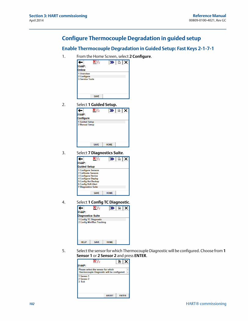
102
Reference Manual00809-0100-4021, Rev GC
Section 3: HART commissioningApril 2014
HART® commissioning
Configure Thermocouple Degradation in guided setup
Enable Thermocouple Degradation in Guided Setup: Fast Keys 2-1-7-1
1. From the Home Screen, select 2 Configure.
2. Select 1 Guided Setup.
3. Select 7 Diagnostics Suite.
4. Select 1 Config TC Diagnostic.
5. Select the sensor for which Thermocouple Diagnostic will be configured. Choose from 1 Sensor 1 or 2 Sensor 2 and press ENTER.
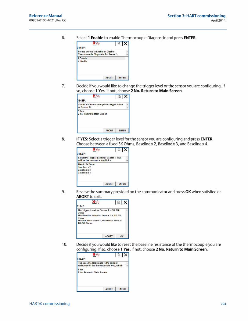
103
Reference Manual 00809-0100-4021, Rev GC
Section 3: HART commissioningApril 2014
HART® commissioning
6. Select 1 Enable to enable Thermocouple Diagnostic and press ENTER.
7. Decide if you would like to change the trigger level or the sensor you are configuring. If so, choose 1 Yes. If not, choose 2 No. Return to Main Screen.
8. IF YES: Select a trigger level for the sensor you are configuring and press ENTER. Choose between a fixed 5K Ohms, Baseline x 2, Baseline x 3, and Baseline x 4.
9. Review the summary provided on the communicator and press OK when satisfied or ABORT to exit.
10. Decide if you would like to reset the baseline resistance of the thermocouple you are configuring. If so, choose 1 Yes. If not, choose 2 No. Return to Main Screen.
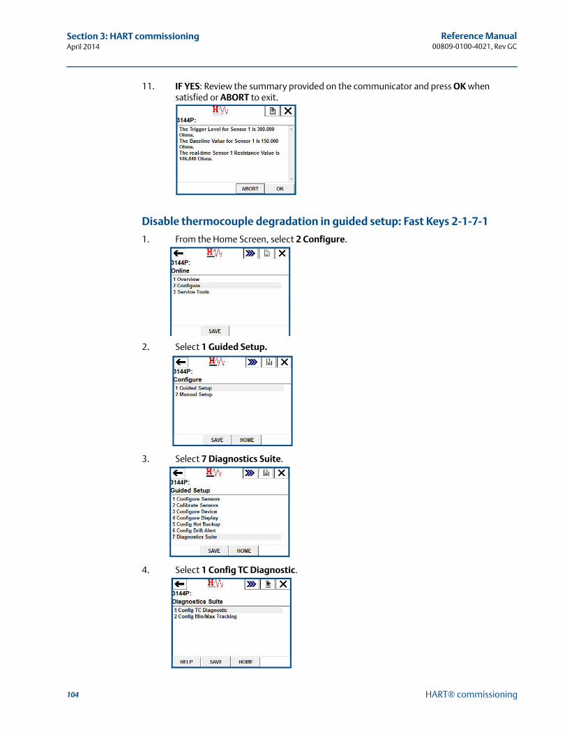
104
Reference Manual00809-0100-4021, Rev GC
Section 3: HART commissioningApril 2014
HART® commissioning
11. IF YES: Review the summary provided on the communicator and press OK when satisfied or ABORT to exit.
Disable thermocouple degradation in guided setup: Fast Keys 2-1-7-1
1. From the Home Screen, select 2 Configure.
2. Select 1 Guided Setup.
3. Select 7 Diagnostics Suite.
4. Select 1 Config TC Diagnostic.
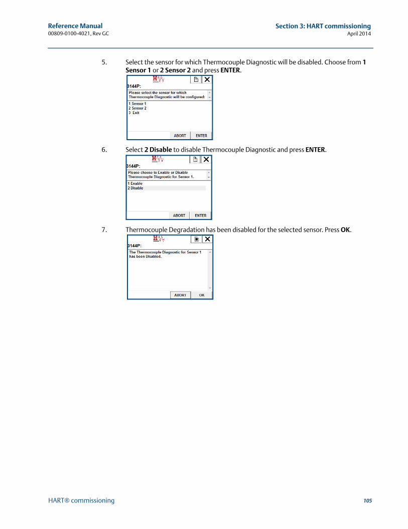
105
Reference Manual 00809-0100-4021, Rev GC
Section 3: HART commissioningApril 2014
HART® commissioning
5. Select the sensor for which Thermocouple Diagnostic will be disabled. Choose from 1 Sensor 1 or 2 Sensor 2 and press ENTER.
6. Select 2 Disable to disable Thermocouple Diagnostic and press ENTER.
7. Thermocouple Degradation has been disabled for the selected sensor. Press OK.
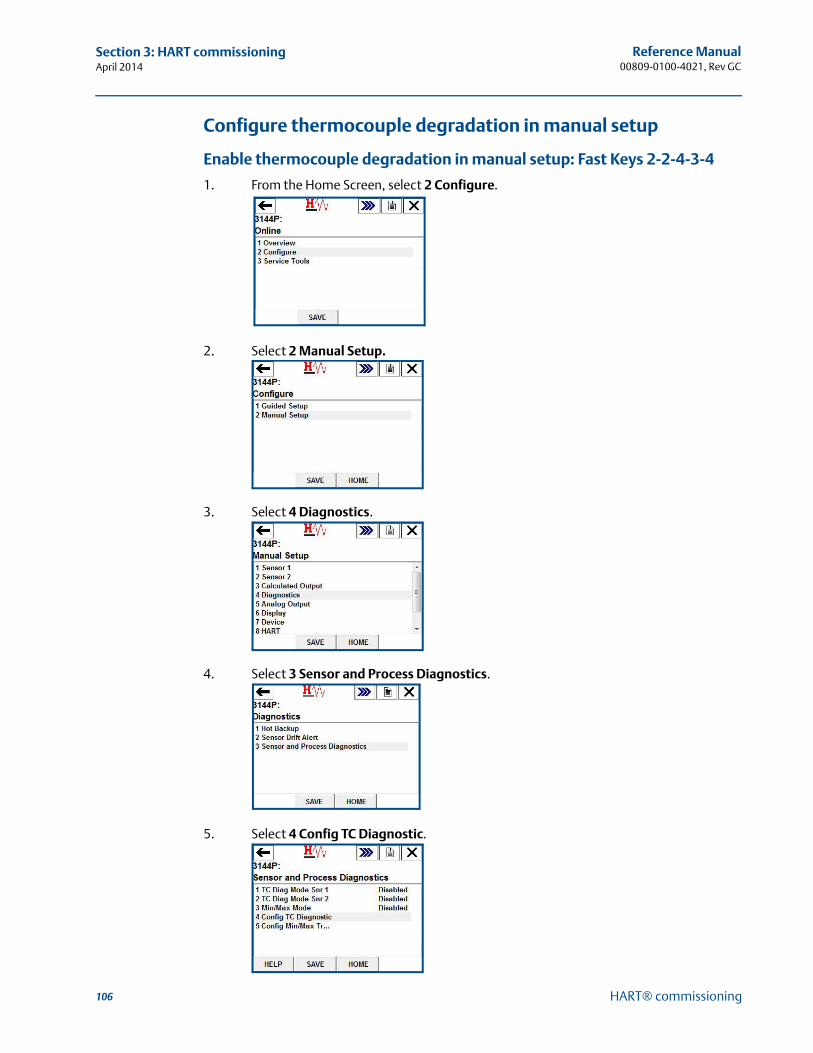
106
Reference Manual00809-0100-4021, Rev GC
Section 3: HART commissioningApril 2014
HART® commissioning
Configure thermocouple degradation in manual setup
Enable thermocouple degradation in manual setup: Fast Keys 2-2-4-3-4
1. From the Home Screen, select 2 Configure.
2. Select 2 Manual Setup.
3. Select 4 Diagnostics.
4. Select 3 Sensor and Process Diagnostics.
5. Select 4 Config TC Diagnostic.

107
Reference Manual 00809-0100-4021, Rev GC
Section 3: HART commissioningApril 2014
HART® commissioning
6. Select the sensor for which Thermocouple Diagnostic will be configured. Choose from 1 Sensor 1 or 2 Sensor 2 and press ENTER. Select 3 Exit to exit the setup.
7. Select 1 Enable to enable Thermocouple Diagnostic and press ENTER.
8. Decide if you would like to change the trigger level or the sensor you are configuring. If so, choose 1 Yes. If not, choose 2 No. Return to Main Screen.
9. IF YES: Select a trigger level for the sensor you are configuring and press ENTER. Choose between a fixed 5K Ohms, Baseline x 2, Baseline x 3, and Baseline x 4.
10. Review the summary provided on the communicator and press OK when satisfied or ABORT to exit.
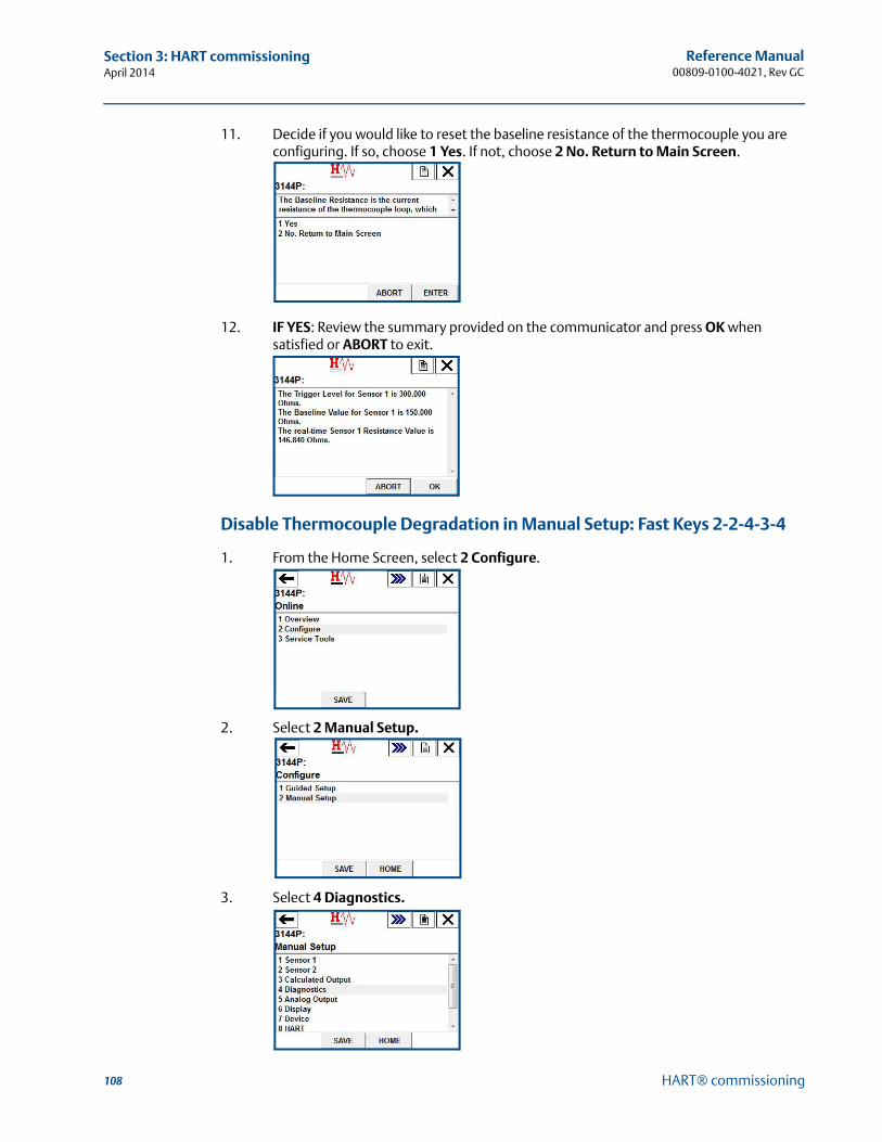
108
Reference Manual00809-0100-4021, Rev GC
Section 3: HART commissioningApril 2014
HART® commissioning
11. Decide if you would like to reset the baseline resistance of the thermocouple you are configuring. If so, choose 1 Yes. If not, choose 2 No. Return to Main Screen.
12. IF YES: Review the summary provided on the communicator and press OK when satisfied or ABORT to exit.
Disable Thermocouple Degradation in Manual Setup: Fast Keys 2-2-4-3-4
1. From the Home Screen, select 2 Configure.
2. Select 2 Manual Setup.
3. Select 4 Diagnostics.
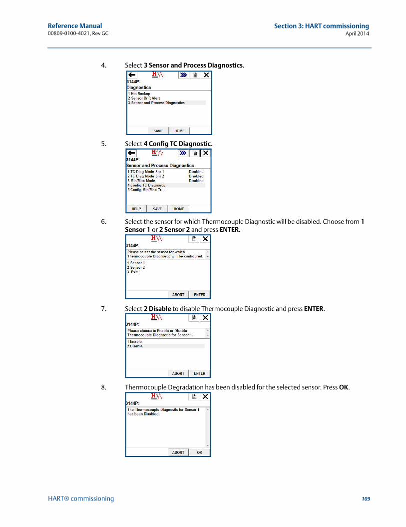
109
Reference Manual 00809-0100-4021, Rev GC
Section 3: HART commissioningApril 2014
HART® commissioning
4. Select 3 Sensor and Process Diagnostics.
5. Select 4 Config TC Diagnostic.
6. Select the sensor for which Thermocouple Diagnostic will be disabled. Choose from 1 Sensor 1 or 2 Sensor 2 and press ENTER.
7. Select 2 Disable to disable Thermocouple Diagnostic and press ENTER.
8. Thermocouple Degradation has been disabled for the selected sensor. Press OK.

110
Reference Manual00809-0100-4021, Rev GC
Section 3: HART commissioningApril 2014
HART® commissioning
Active Thermocouple Degradation alertsTo verify that Thermocouple Degradation is enabled: Fast Keys 2-2-41. From the Home Screen, select 2 Configure.
2. Select 2 Manual Setup.
3. Select 4 Diagnostics.
4. Select 3 Sensor and Process Diagnostics.
5. 1 TC Diag Mode Snr 1 will show Enabled if Thermocouple Diagnostic is enabled for Sensor 1, and Disabled if Thermocouple Diagnostic is disabled.
2 TC Diag Mode Snr 2 will show Enabled if Thermocouple Diagnostic is enabled for Sensor 2, and Disabled if Thermocouple Diagnostic is disabled.
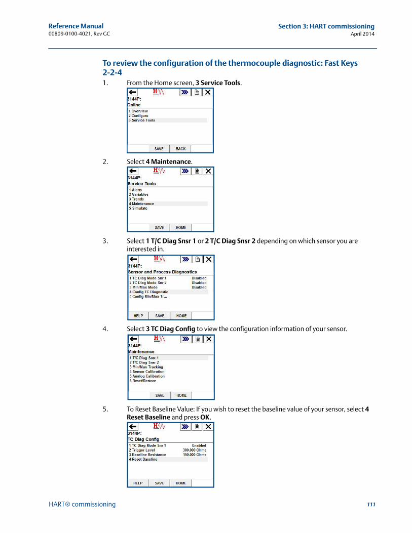
111
Reference Manual 00809-0100-4021, Rev GC
Section 3: HART commissioningApril 2014
HART® commissioning
To review the configuration of the thermocouple diagnostic: Fast Keys 2-2-41. From the Home screen, 3 Service Tools.
2. Select 4 Maintenance.
3. Select 1 T/C Diag Snsr 1 or 2 T/C Diag Snsr 2 depending on which sensor you are interested in.
4. Select 3 TC Diag Config to view the configuration information of your sensor.
5. To Reset Baseline Value: If you wish to reset the baseline value of your sensor, select 4 Reset Baseline and press OK.
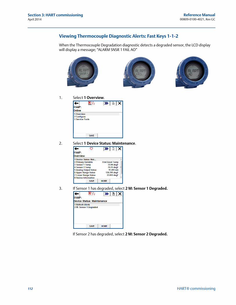
112
Reference Manual00809-0100-4021, Rev GC
Section 3: HART commissioningApril 2014
HART® commissioning
Viewing Thermocouple Diagnostic Alerts: Fast Keys 1-1-2
When the Thermocouple Degradation diagnostic detects a degraded sensor, the LCD display will display a message; “ALARM SNSR 1 FAIL AO”
1. Select 1 Overview.
2. Select 1 Device Status: Maintenance.
3. If Sensor 1 has degraded, select 2 M: Sensor 1 Degraded.
If Sensor 2 has degraded, select 2 M: Sensor 2 Degraded.
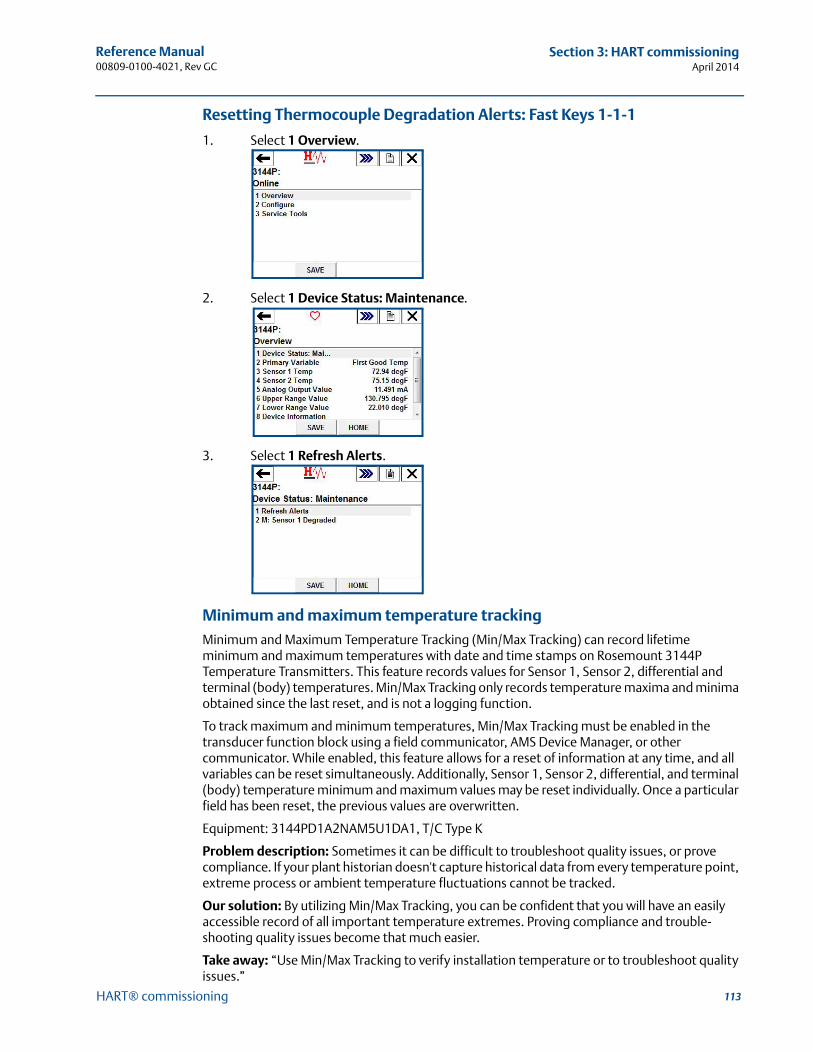
113
Reference Manual 00809-0100-4021, Rev GC
Section 3: HART commissioningApril 2014
HART® commissioning
Resetting Thermocouple Degradation Alerts: Fast Keys 1-1-1
1. Select 1 Overview.
2. Select 1 Device Status: Maintenance.
3. Select 1 Refresh Alerts.
Minimum and maximum temperature tracking
Minimum and Maximum Temperature Tracking (Min/Max Tracking) can record lifetime minimum and maximum temperatures with date and time stamps on Rosemount 3144P Temperature Transmitters. This feature records values for Sensor 1, Sensor 2, differential and terminal (body) temperatures. Min/Max Tracking only records temperature maxima and minima obtained since the last reset, and is not a logging function.
To track maximum and minimum temperatures, Min/Max Tracking must be enabled in the transducer function block using a field communicator, AMS Device Manager, or other communicator. While enabled, this feature allows for a reset of information at any time, and all variables can be reset simultaneously. Additionally, Sensor 1, Sensor 2, differential, and terminal (body) temperature minimum and maximum values may be reset individually. Once a particular field has been reset, the previous values are overwritten.
Equipment: 3144PD1A2NAM5U1DA1, T/C Type K
Problem description: Sometimes it can be difficult to troubleshoot quality issues, or prove compliance. If your plant historian doesn't capture historical data from every temperature point, extreme process or ambient temperature fluctuations cannot be tracked.
Our solution: By utilizing Min/Max Tracking, you can be confident that you will have an easily accessible record of all important temperature extremes. Proving compliance and trouble-shooting quality issues become that much easier.
Take away: “Use Min/Max Tracking to verify installation temperature or to troubleshoot quality issues.”

114
Reference Manual00809-0100-4021, Rev GC
Section 3: HART commissioningApril 2014
HART® commissioning
Configure Min/Max Tracking in guided setup
Enable Min/Max Tracking in guided setup: Fast Keys 2-1-7-2
1. From the Home screen, select 2 Configure.
2. Select 1 Guided Setup.
3. Select 7 Diagnostics Suite.
4. Select 2 Config Min/Max Tracking.
5. Select 1 Enable to enable the Min/Max Tracking feature and press ENTER.
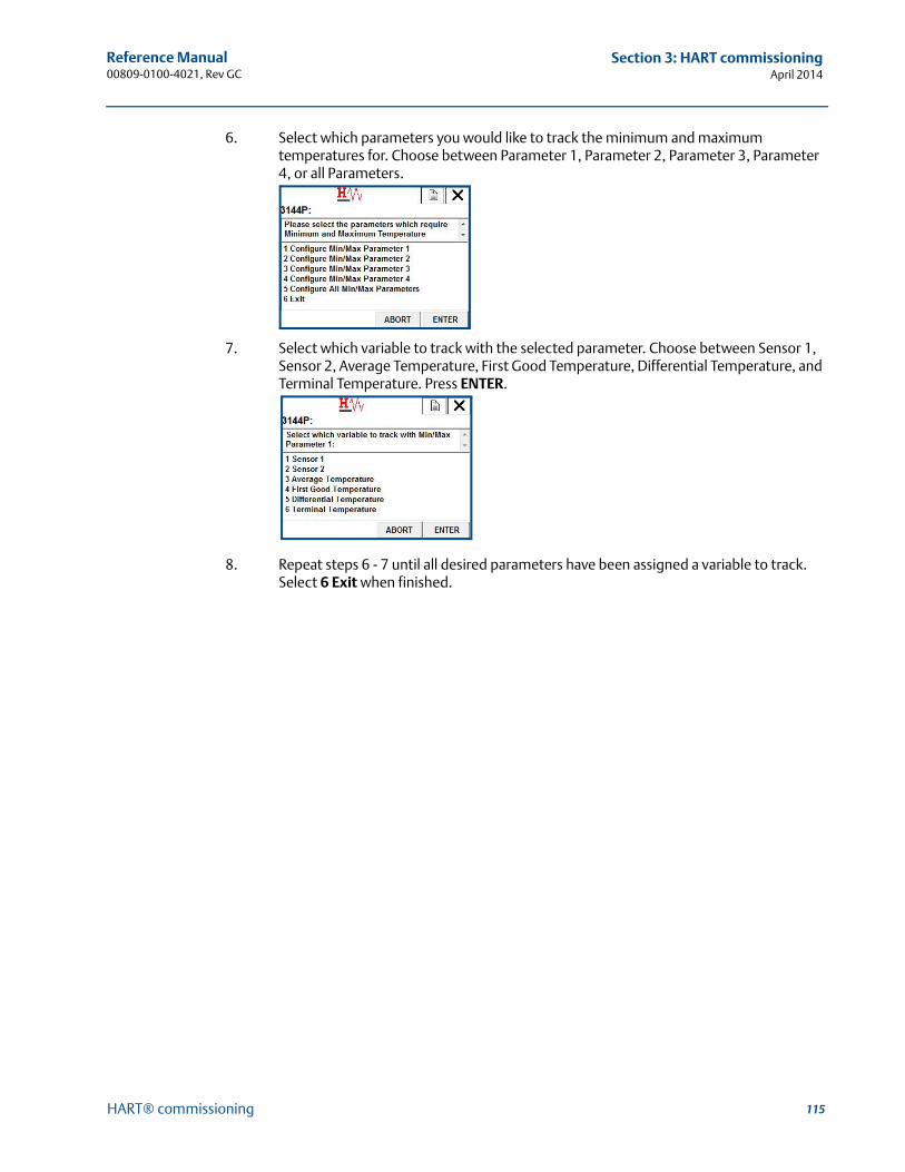
115
Reference Manual 00809-0100-4021, Rev GC
Section 3: HART commissioningApril 2014
HART® commissioning
6. Select which parameters you would like to track the minimum and maximum temperatures for. Choose between Parameter 1, Parameter 2, Parameter 3, Parameter 4, or all Parameters.
7. Select which variable to track with the selected parameter. Choose between Sensor 1, Sensor 2, Average Temperature, First Good Temperature, Differential Temperature, and Terminal Temperature. Press ENTER.
8. Repeat steps 6 - 7 until all desired parameters have been assigned a variable to track. Select 6 Exit when finished.
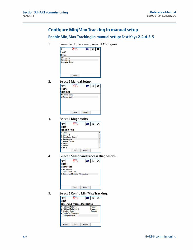
116
Reference Manual00809-0100-4021, Rev GC
Section 3: HART commissioningApril 2014
HART® commissioning
Configure Min/Max Tracking in manual setup
Enable Min/Max Tracking in manual setup: Fast Keys 2-2-4-3-5
1. From the Home screen, select 2 Configure.
2. Select 2 Manual Setup.
3. Select 4 Diagnostics.
4. Select 3 Sensor and Process Diagnostics.
5. Select 5 Config Min/Max Tracking.
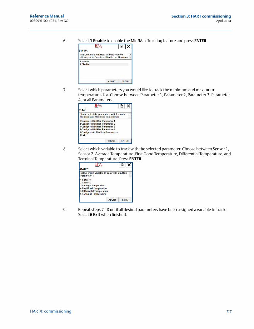
117
Reference Manual 00809-0100-4021, Rev GC
Section 3: HART commissioningApril 2014
HART® commissioning
6. Select 1 Enable to enable the Min/Max Tracking feature and press ENTER.
7. Select which parameters you would like to track the minimum and maximum temperatures for. Choose between Parameter 1, Parameter 2, Parameter 3, Parameter 4, or all Parameters.
8. Select which variable to track with the selected parameter. Choose between Sensor 1, Sensor 2, Average Temperature, First Good Temperature, Differential Temperature, and Terminal Temperature. Press ENTER.
9. Repeat steps 7 - 8 until all desired parameters have been assigned a variable to track. Select 6 Exit when finished.
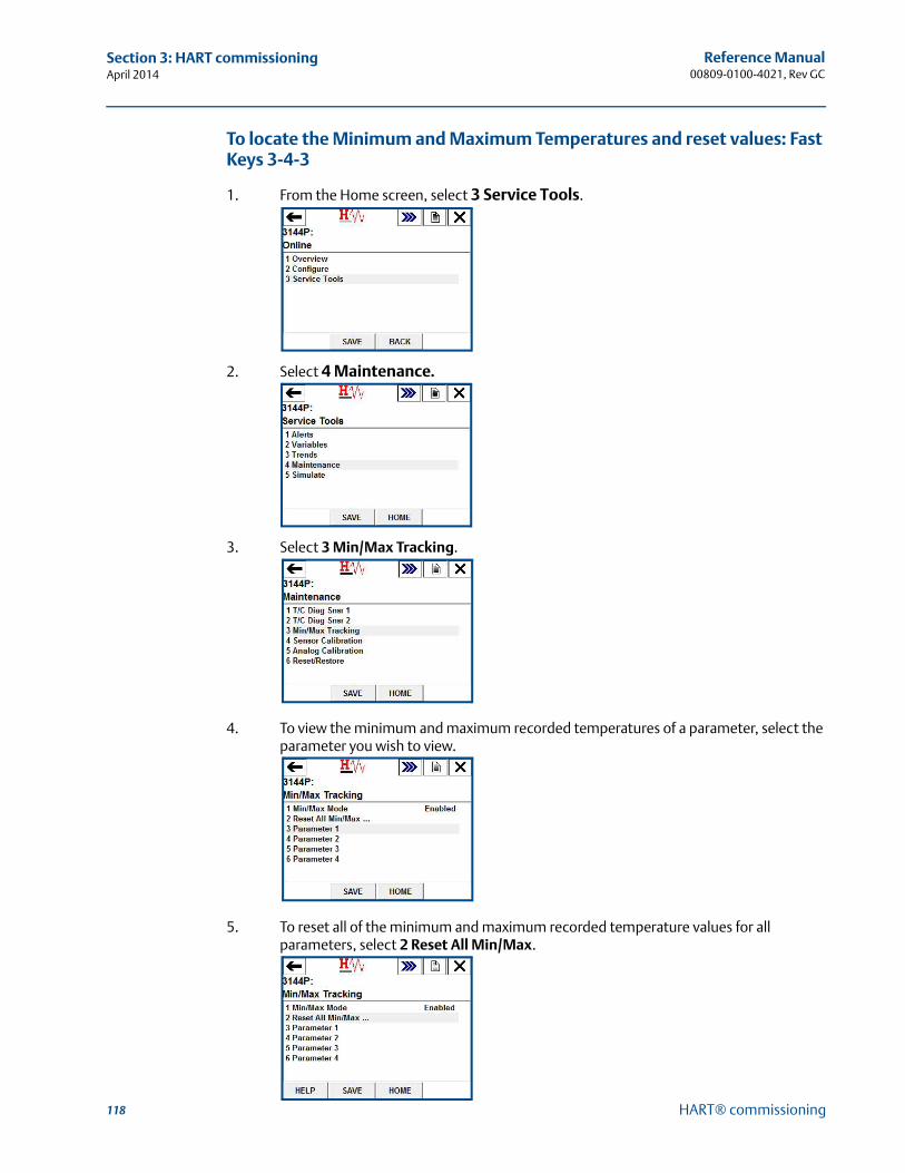
118
Reference Manual00809-0100-4021, Rev GC
Section 3: HART commissioningApril 2014
HART® commissioning
To locate the Minimum and Maximum Temperatures and reset values: Fast Keys 3-4-3
1. From the Home screen, select 3 Service Tools.
2. Select 4 Maintenance.
3. Select 3 Min/Max Tracking.
4. To view the minimum and maximum recorded temperatures of a parameter, select the parameter you wish to view.
5. To reset all of the minimum and maximum recorded temperature values for all parameters, select 2 Reset All Min/Max.
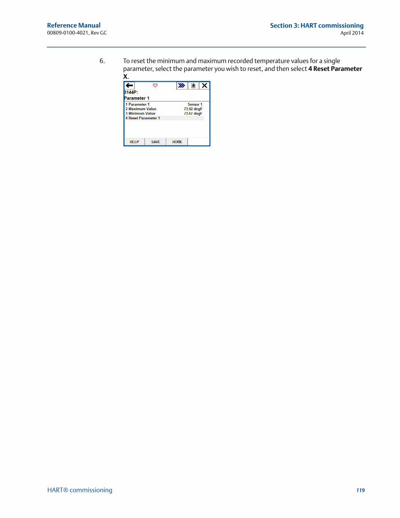
119
Reference Manual 00809-0100-4021, Rev GC
Section 3: HART commissioningApril 2014
HART® commissioning
6. To reset the minimum and maximum recorded temperature values for a single parameter, select the parameter you wish to reset, and then select 4 Reset Parameter X.
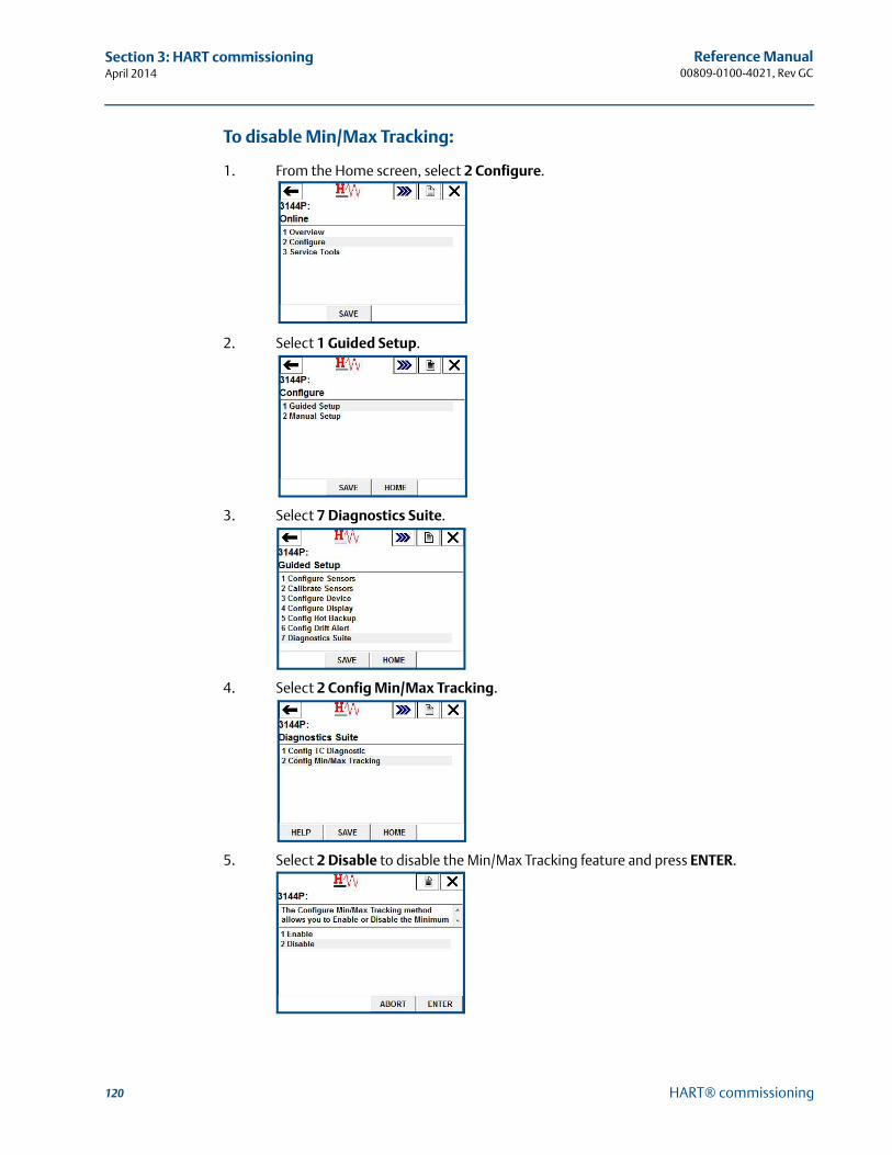
120
Reference Manual00809-0100-4021, Rev GC
Section 3: HART commissioningApril 2014
HART® commissioning
To disable Min/Max Tracking:
1. From the Home screen, select 2 Configure.
2. Select 1 Guided Setup.
3. Select 7 Diagnostics Suite.
4. Select 2 Config Min/Max Tracking.
5. Select 2 Disable to disable the Min/Max Tracking feature and press ENTER.
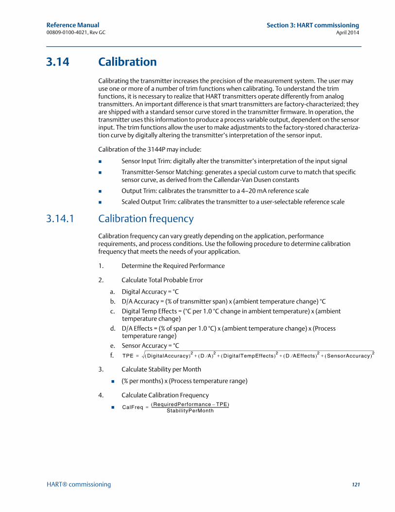
121
Reference Manual 00809-0100-4021, Rev GC
Section 3: HART commissioningApril 2014
HART® commissioning
3.14 Calibration
Calibrating the transmitter increases the precision of the measurement system. The user may use one or more of a number of trim functions when calibrating. To understand the trim functions, it is necessary to realize that HART transmitters operate differently from analog transmitters. An important difference is that smart transmitters are factory-characterized; they are shipped with a standard sensor curve stored in the transmitter firmware. In operation, the transmitter uses this information to produce a process variable output, dependent on the sensor input. The trim functions allow the user to make adjustments to the factory-stored characteriza-tion curve by digitally altering the transmitter’s interpretation of the sensor input.
Calibration of the 3144P may include:
Sensor Input Trim: digitally alter the transmitter’s interpretation of the input signal
Transmitter-Sensor Matching: generates a special custom curve to match that specific sensor curve, as derived from the Callendar-Van Dusen constants
Output Trim: calibrates the transmitter to a 4–20 mA reference scale
Scaled Output Trim: calibrates the transmitter to a user-selectable reference scale
3.14.1 Calibration frequency
Calibration frequency can vary greatly depending on the application, performance requirements, and process conditions. Use the following procedure to determine calibration frequency that meets the needs of your application.
1. Determine the Required Performance
2. Calculate Total Probable Error
a. Digital Accuracy = °C
b. D/A Accuracy = (% of transmitter span) x (ambient temperature change) °C
c. Digital Temp Effects = (°C per 1.0 °C change in ambient temperature) x (ambient temperature change)
d. D/A Effects = (% of span per 1.0 °C) x (ambient temperature change) x (Process temperature range)
e. Sensor Accuracy = °C
f.
3. Calculate Stability per Month
(% per months) x (Process temperature range)
4. Calculate Calibration Frequency
TPE DigitalAccuracy 2 D A 2 DigitalTempEffects 2 D A Effects 2 SensorAccuracy 2+ + + +=
CalFreq RequiredPerformance TPE– Stabil ityPerMonth
------------------------------------------------------------------------------------------=
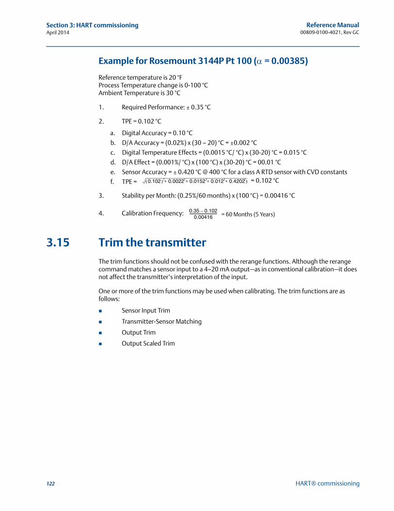
122
Reference Manual00809-0100-4021, Rev GC
Section 3: HART commissioningApril 2014
HART® commissioning
Example for Rosemount 3144P Pt 100 ( = 0.00385)
Reference temperature is 20 °FProcess Temperature change is 0-100 °CAmbient Temperature is 30 °C
1. Required Performance: ± 0.35 °C
2. TPE = 0.102 °C
a. Digital Accuracy = 0.10 °C
b. D/A Accuracy = (0.02%) x (30 – 20) °C = ±0.002 °C
c. Digital Temperature Effects = (0.0015 °C/ °C) x (30-20) °C = 0.015 °C
d. D/A Effect = (0.001%/ °C) x (100 °C) x (30-20) °C = 00.01 °C
e. Sensor Accuracy = ± 0.420 °C @ 400 °C for a class A RTD sensor with CVD constants
f. TPE =
3. Stability per Month: (0.25%/60 months) x (100 °C) = 0.00416 °C
4. Calibration Frequency:
3.15 Trim the transmitter
The trim functions should not be confused with the rerange functions. Although the rerange command matches a sensor input to a 4–20 mA output—as in conventional calibration—it does not affect the transmitter’s interpretation of the input.
One or more of the trim functions may be used when calibrating. The trim functions are as follows:
Sensor Input Trim
Transmitter-Sensor Matching
Output Trim
Output Scaled Trim
0.102 0.0022 0.0152 0.012 0.4202 + + + + = 0.102 °C22222
0.35 0.102–0.00416
-------------------------------- = 60 Months (5 Years)
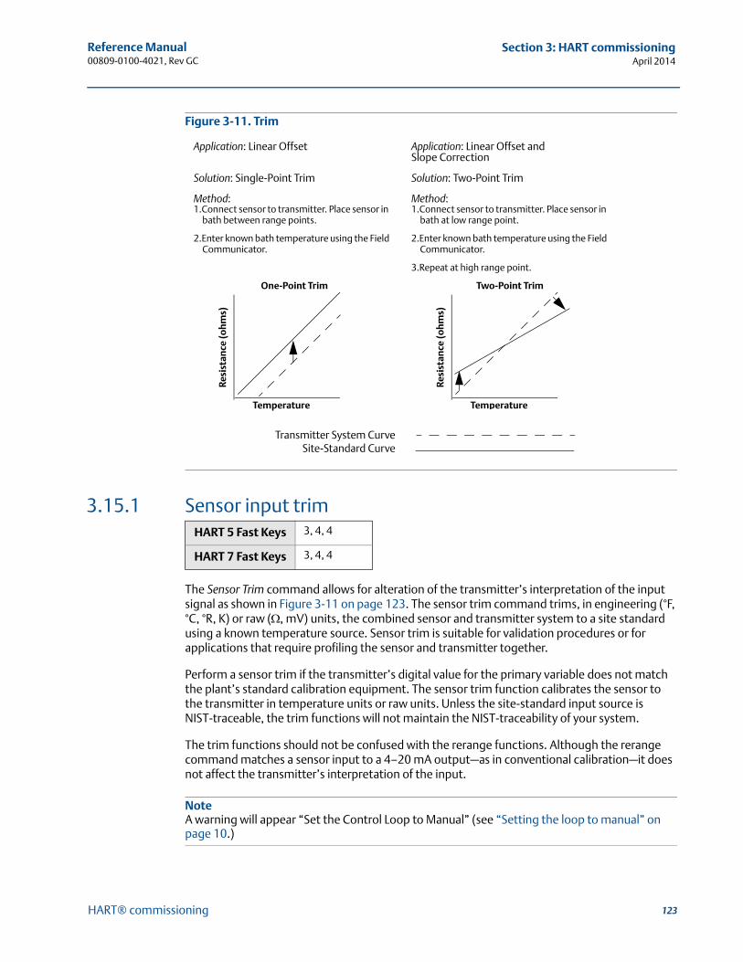
123
Reference Manual 00809-0100-4021, Rev GC
Section 3: HART commissioningApril 2014
HART® commissioning
Figure 3-11. Trim
3.15.1 Sensor input trim
The Sensor Trim command allows for alteration of the transmitter’s interpretation of the input signal as shown in Figure 3-11 on page 123. The sensor trim command trims, in engineering (°F, °C, °R, K) or raw (, mV) units, the combined sensor and transmitter system to a site standard using a known temperature source. Sensor trim is suitable for validation procedures or for applications that require profiling the sensor and transmitter together.
Perform a sensor trim if the transmitter’s digital value for the primary variable does not match the plant’s standard calibration equipment. The sensor trim function calibrates the sensor to the transmitter in temperature units or raw units. Unless the site-standard input source is NIST-traceable, the trim functions will not maintain the NIST-traceability of your system.
The trim functions should not be confused with the rerange functions. Although the rerange command matches a sensor input to a 4–20 mA output—as in conventional calibration—it does not affect the transmitter’s interpretation of the input.
NoteA warning will appear “Set the Control Loop to Manual” (see “Setting the loop to manual” on page 10.)
Application: Linear Offset Application: Linear Offset and Slope Correction
Solution: Single-Point Trim Solution: Two-Point Trim
Method:1.Connect sensor to transmitter. Place sensor in
bath between range points.
2.Enter known bath temperature using the Field Communicator.
Method:1.Connect sensor to transmitter. Place sensor in
bath at low range point.
2.Enter known bath temperature using the Field Communicator.
3.Repeat at high range point.
One-Point Trim Two-Point Trim
Transmitter System Curve Site-Standard Curve
HART 5 Fast Keys 3, 4, 4
HART 7 Fast Keys 3, 4, 4
Resi
stan
ce (o
hm
s)
Temperature
Resi
stan
ce (o
hm
s)
Temperature
124
Reference Manual00809-0100-4021, Rev GC
Section 3: HART commissioningApril 2014
HART® commissioning
3.15.2 Active calibrator and EMF compensation
The transmitter operates with a pulsating sensor current to allow EMF compensation and detection of open sensor conditions. Because some calibration equipment requires a steady sensor current to function properly, the “Active Calibrator Mode” feature should be used when an active calibrator is connected. Enabling this mode temporarily sets the transmitter to provide steady sensor current unless two sensor inputs are configured. Disable this mode before putting the transmitter back into the process to set the transmitter back to pulsating current. “Active Calibrator Mode” is volatile and will automatically be disabled when a Master Reset is performed (through HART) or when the power is cycled.
EMF compensation allows the transmitter to provide sensor measurements that are unaffected by unwanted voltages, typically due to thermal EMFs in the equipment connected to the transmitter, or by some types of calibration equipment. If this equipment also requires steady sensor current, the transmitter must be set to “Active Calibrator Mode.” However, the steady current does not allow the transmitter to perform EMF compensation and as a result, a difference in readings between the active calibrator and actual sensor may exist.
If a reading difference is experienced and is greater than the plant’s accuracy specification allows, perform a sensor trim with “Active Calibrator Mode” disabled. In this case, an active calibrator capable of tolerating pulsating sensor current must be used or the actual sensors must be connected to the transmitter. When the field communicator or AMS Device Manager asks if an active calibrator is being used when the sensor trim routine is entered, select No to leave the “Active Calibrator Mode” disabled.
In temperature measurement loops using RTDs, small voltages, called EMFs, can be induced on the sensor wires, increasing the effective resistance and causing false temperature readings. For example, a 12 mV reading equates to 390F or 60ohm error for a PT100 385 RTD. The Emerson EMF Compensation detects these externally induced voltages and eliminates the erroneous voltages from the calculations performed by the transmitters. Externally induced voltages come from motors, calibration devices (dry block calibrator), etc.
How it works: Our transmitter provides RTD measurement updates at a rate of less than one second for a single sensor. This measurement update consists of a series of smaller measurement scans. A part of these smaller measurement scans is a check for EMF induced voltage, up to 12 mV, on the sensor loop. The transmitter is designed to compensate out the induced voltage up to 12 mV and provide a corrected temperature value. Beyond 12 mV, the transmitter will notify the user that “Excess EMF” is present and warn them of possible inaccuracies in the temperature measurement due to excessive induced voltage on the RTD sensor loop. In the case of excessive EMF in the transmitter, it is recommended that the user identify the external sources of electromagnetic interference and isolate them from the transmitter and RTD sensor wiring.
HART 5 Fast Keys 3, 4, 4, 4
HART 7 Fast Keys 3, 4, 4, 4
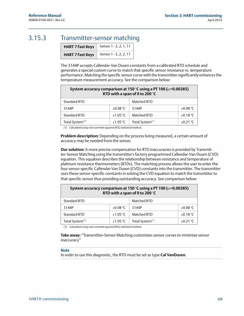
125
Reference Manual 00809-0100-4021, Rev GC
Section 3: HART commissioningApril 2014
HART® commissioning
3.15.3 Transmitter-sensor matching
The 3144P accepts Callendar-Van Dusen constants from a calibrated RTD schedule and generates a special custom curve to match that specific sensor resistance vs. temperature performance. Matching the specific sensor curve with the transmitter significantly enhances the temperature measurement accuracy. See the comparison below:
Problem description: Depending on the process being measured, a certain amount of accuracy may be needed from the sensor.
Our solution: A more precise compensation for RTD inaccuracies is provided by Transmit-ter-Sensor Matching using the transmitter's factory programmed Callendar-Van Dusen (CVD) equation. This equation describes the relationship between resistance and temperature of platinum resistance thermometers (RTDs). The matching process allows the user to enter the four sensor specific Callendar-Van Dusen (CVD) constants into the transmitter. The transmitter uses these sensor-specific constants in solving the CVD equation to match the transmitter to that specific sensor thus providing outstanding accuracy. See comparison below:
Take away: “Transmitter-Sensor Matching customizes sensor curves to minimize sensor inaccuracy”
NoteIn order to use this diagnostic, the RTD must be set as type Cal VanDusen.
HART 7 Fast Keys Sensor 1 - 2, 2, 1, 11
HART 7 Fast Keys Sensor 1 - 2, 2, 2, 11
System accuracy comparison at 150 °C using a PT 100 (=0.00385) RTD with a span of 0 to 200 °C
Standard RTD Matched RTD
3144P ±0.08 °C 3144P ±0.08 °C
Standard RTD ±1.05 °C Matched RTD ±0.18 °C
Total System(1)
(1) Calculated using root-summed-squared (RSS) statistical method.
±1.05 °C Total System(1) ±0.21 °C
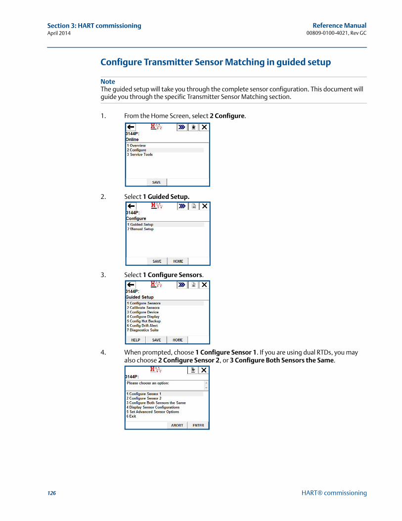
126
Reference Manual00809-0100-4021, Rev GC
Section 3: HART commissioningApril 2014
HART® commissioning
Configure Transmitter Sensor Matching in guided setup
NoteThe guided setup will take you through the complete sensor configuration. This document will guide you through the specific Transmitter Sensor Matching section.
1. From the Home Screen, select 2 Configure.
2. Select 1 Guided Setup.
3. Select 1 Configure Sensors.
4. When prompted, choose 1 Configure Sensor 1. If you are using dual RTDs, you may also choose 2 Configure Sensor 2, or 3 Configure Both Sensors the Same.
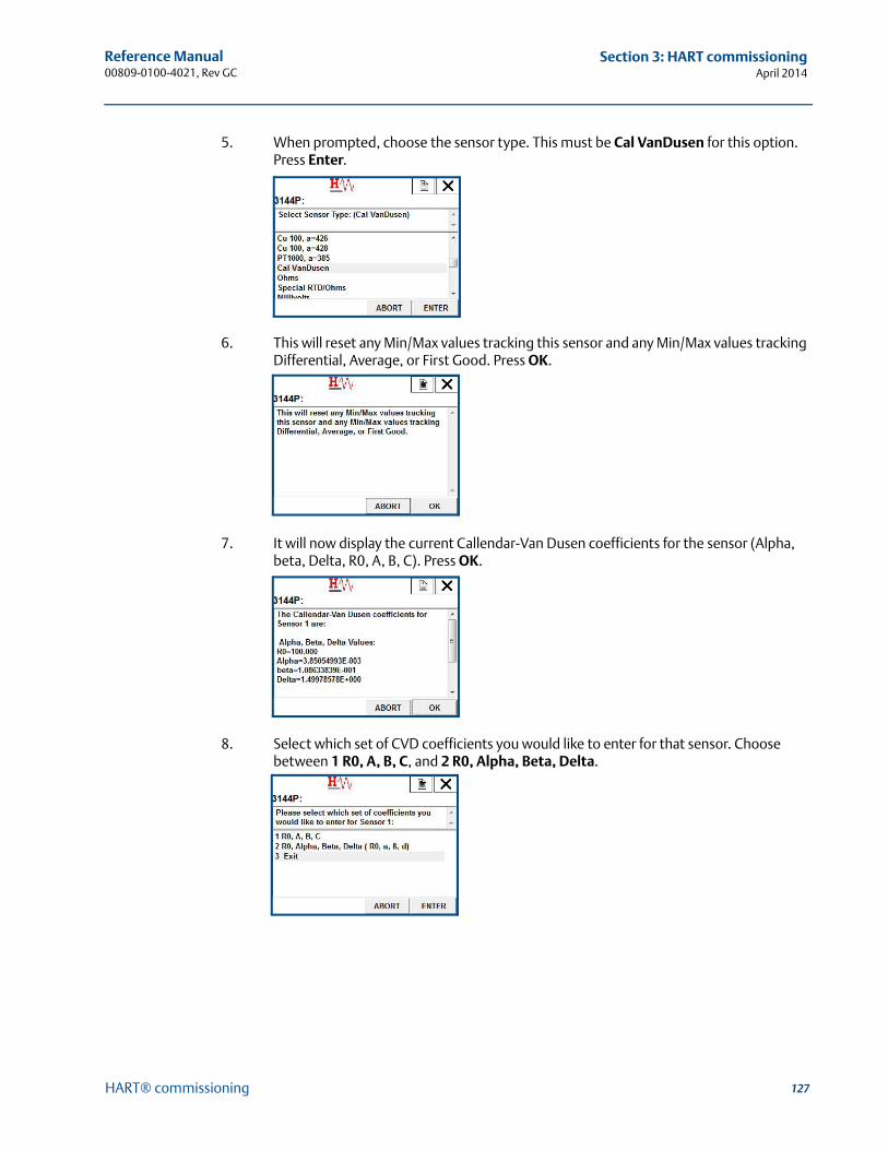
127
Reference Manual 00809-0100-4021, Rev GC
Section 3: HART commissioningApril 2014
HART® commissioning
5. When prompted, choose the sensor type. This must be Cal VanDusen for this option. Press Enter.
6. This will reset any Min/Max values tracking this sensor and any Min/Max values tracking Differential, Average, or First Good. Press OK.
7. It will now display the current Callendar-Van Dusen coefficients for the sensor (Alpha, beta, Delta, R0, A, B, C). Press OK.
8. Select which set of CVD coefficients you would like to enter for that sensor. Choose between 1 R0, A, B, C, and 2 R0, Alpha, Beta, Delta.
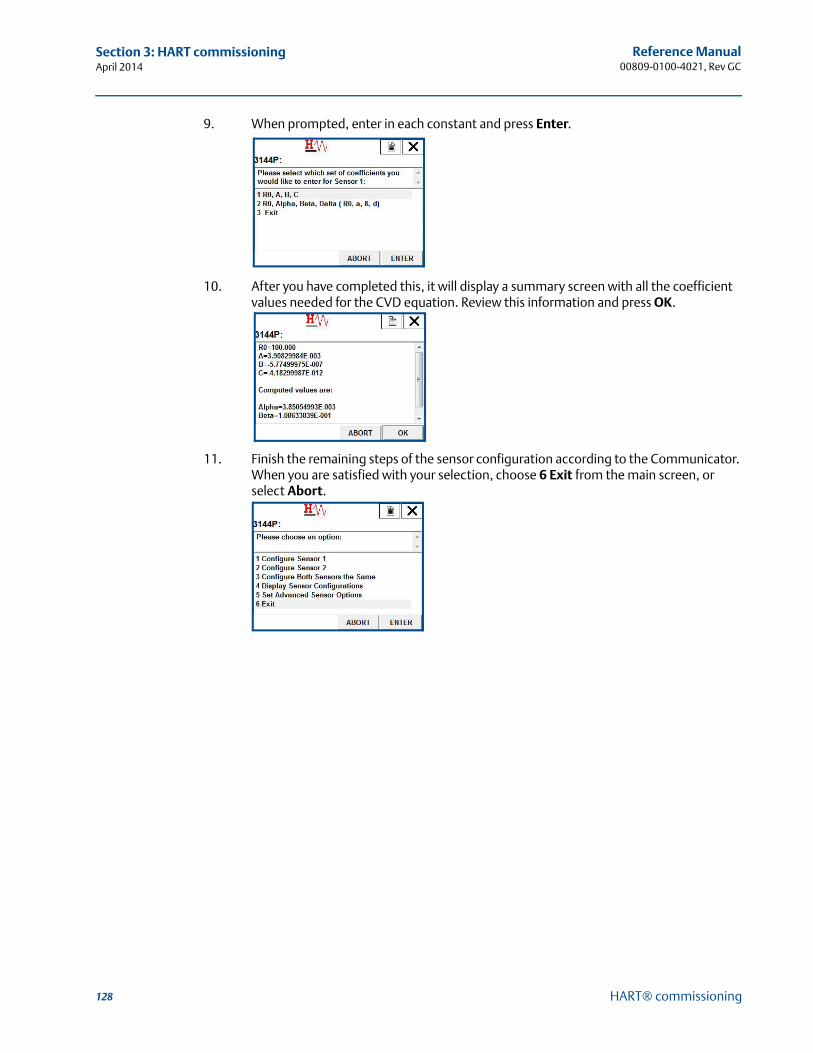
128
Reference Manual00809-0100-4021, Rev GC
Section 3: HART commissioningApril 2014
HART® commissioning
9. When prompted, enter in each constant and press Enter.
10. After you have completed this, it will display a summary screen with all the coefficient values needed for the CVD equation. Review this information and press OK.
11. Finish the remaining steps of the sensor configuration according to the Communicator. When you are satisfied with your selection, choose 6 Exit from the main screen, or select Abort.
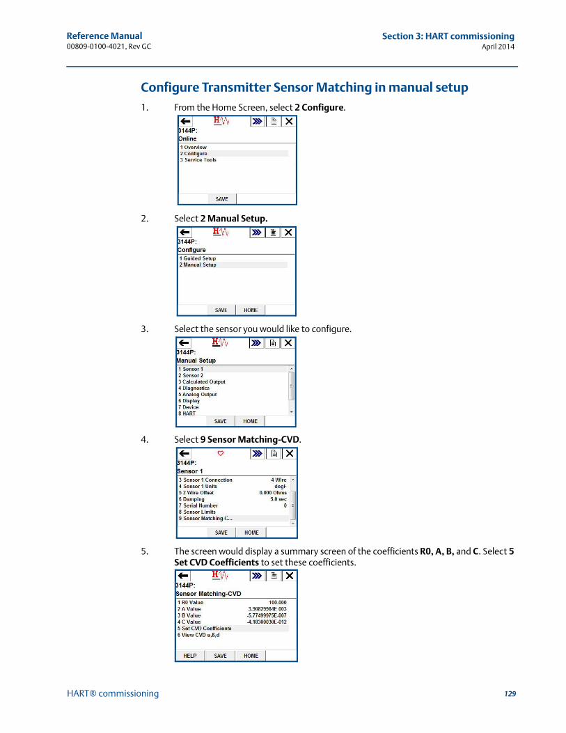
129
Reference Manual 00809-0100-4021, Rev GC
Section 3: HART commissioningApril 2014
HART® commissioning
Configure Transmitter Sensor Matching in manual setup1. From the Home Screen, select 2 Configure.
2. Select 2 Manual Setup.
3. Select the sensor you would like to configure.
4. Select 9 Sensor Matching-CVD.
5. The screen would display a summary screen of the coefficients R0, A, B, and C. Select 5 Set CVD Coefficients to set these coefficients.
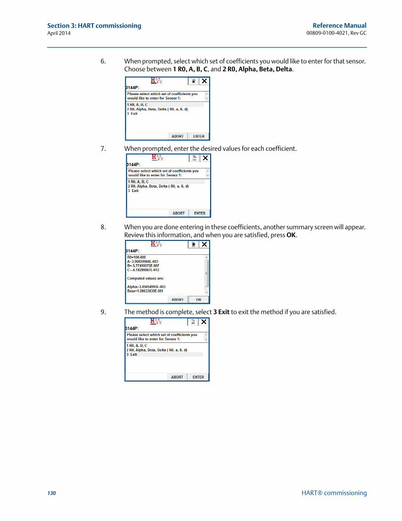
130
Reference Manual00809-0100-4021, Rev GC
Section 3: HART commissioningApril 2014
HART® commissioning
6. When prompted, select which set of coefficients you would like to enter for that sensor. Choose between 1 R0, A, B, C, and 2 R0, Alpha, Beta, Delta.
7. When prompted, enter the desired values for each coefficient.
8. When you are done entering in these coefficients, another summary screen will appear. Review this information, and when you are satisfied, press OK.
9. The method is complete, select 3 Exit to exit the method if you are satisfied.

131
Reference Manual 00809-0100-4021, Rev GC
Section 3: HART commissioningApril 2014
HART® commissioning
View the set CVD coefficients
1. From the Home Screen, select 2 Configure.
2. Select 2 Manual Setup.
3. Select the sensor you would like to configure.
4. Select 9 Sensor Matching-CVD.
5. The screen would display a summary screen of the coefficients R0, A, B, and C. Select 6 View CVD to view those.

132
Reference Manual00809-0100-4021, Rev GC
Section 3: HART commissioningApril 2014
HART® commissioning
The following input constants, included with specially-ordered Rosemount temperature sensors, are required:
R0 = Resistance at Ice PointAlpha = Sensor Specific ConstantBeta = Sensor Specific ConstantDelta = Sensor Specific ConstantOther sensor may have “A, B, or C” values for constants.
NoteWhen the Transmitter-Sensor Matching is disabled, the transmitter reverts to factory trim input. Make certain the transmitter engineering units default correctly before placing the transmitter into service.
3.15.4 D/A output trim or scaled output trim
Perform a D/A output trim (scaled output trim) if the digital value for the primary variable matches the plant standard, but the transmitter’s analog output does not match the digital value on the output device (such as the ampmeter). The output trim function calibrates the transmitter analog output to a 4–20 mA reference scale; the scaled output trim function calibrates to a user-selectable reference scale. To determine the need for an output trim or a scaled output trim, perform a loop test (see “Loop test” on page 98).
Figure 3-12. Dynamics of Smart Temperature Measurement
3.15.5 Output trim
The D/A Trim command allows the user to alter the transmitter’s conversion of the input signal to a 4–20 mA output (see Figure 3-12 on page 132). Calibrate the analog output signal at regular intervals to maintain measurement precision. To perform a digital-to-analog trim, perform the following procedure with the Traditional Fast Key sequence.
HART 5 Fast Keys 3, 4, 5, 1
HART 7 Fast Keys 3, 4, 5, 1
Microprocessor Digital-to-Analog Signal Conversion
Analog-to-Digital Signal Conversion
Transmitter Electronics Module
Sensor and Ohm/mV Trim adjust the signal here
Output and Scaled Output Trim adjust the signal here
Analog Input
Analog Output Field
Communicator
HARTOutput
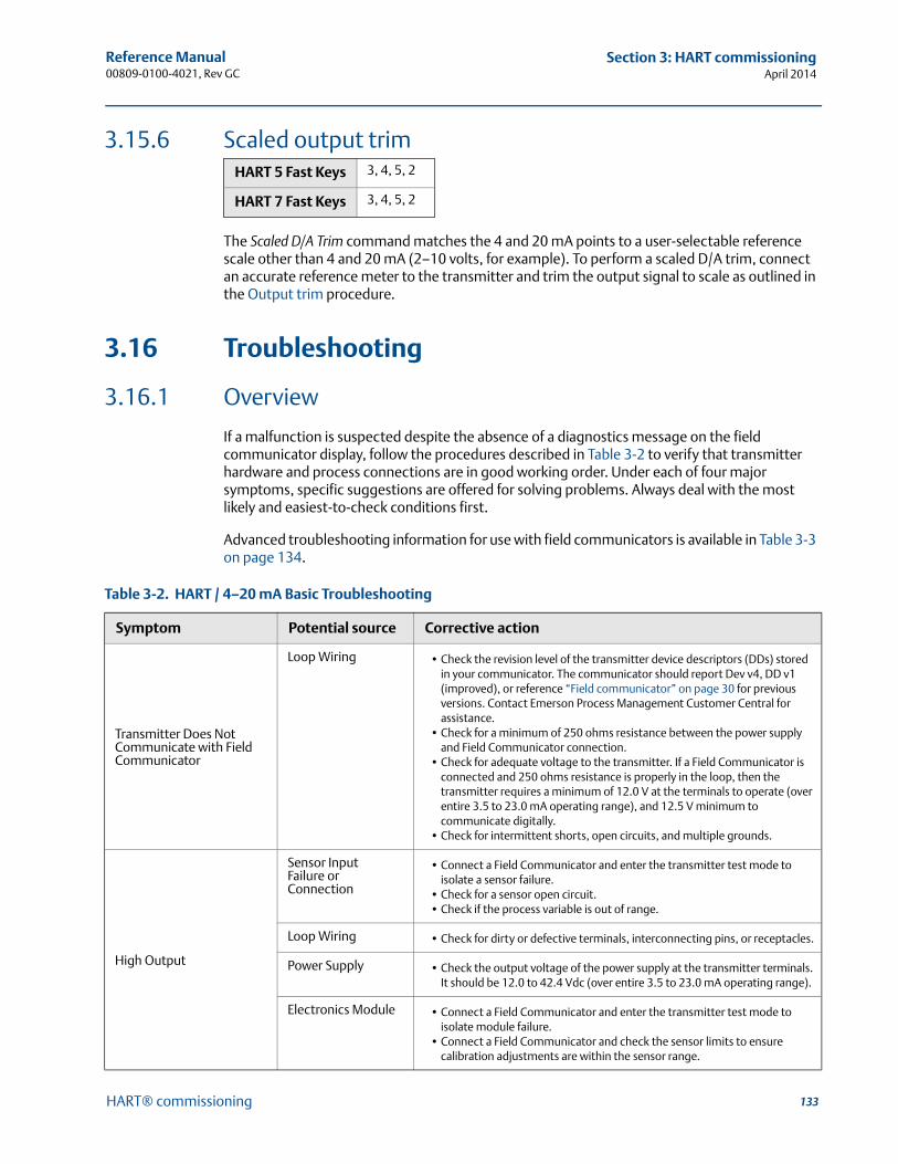
133
Reference Manual 00809-0100-4021, Rev GC
Section 3: HART commissioningApril 2014
HART® commissioning
3.15.6 Scaled output trim
The Scaled D/A Trim command matches the 4 and 20 mA points to a user-selectable reference scale other than 4 and 20 mA (2–10 volts, for example). To perform a scaled D/A trim, connect an accurate reference meter to the transmitter and trim the output signal to scale as outlined in the Output trim procedure.
3.16 Troubleshooting
3.16.1 Overview
If a malfunction is suspected despite the absence of a diagnostics message on the field communicator display, follow the procedures described in Table 3-2 to verify that transmitter hardware and process connections are in good working order. Under each of four major symptoms, specific suggestions are offered for solving problems. Always deal with the most likely and easiest-to-check conditions first.
Advanced troubleshooting information for use with field communicators is available in Table 3-3 on page 134.
HART 5 Fast Keys 3, 4, 5, 2
HART 7 Fast Keys 3, 4, 5, 2
Table 3-2. HART / 4–20 mA Basic Troubleshooting
Symptom Potential source Corrective action
Transmitter Does Not Communicate with Field Communicator
Loop Wiring • Check the revision level of the transmitter device descriptors (DDs) stored in your communicator. The communicator should report Dev v4, DD v1 (improved), or reference “Field communicator” on page 30 for previous versions. Contact Emerson Process Management Customer Central for assistance.
• Check for a minimum of 250 ohms resistance between the power supply and Field Communicator connection.
• Check for adequate voltage to the transmitter. If a Field Communicator is connected and 250 ohms resistance is properly in the loop, then the transmitter requires a minimum of 12.0 V at the terminals to operate (over entire 3.5 to 23.0 mA operating range), and 12.5 V minimum to communicate digitally.
• Check for intermittent shorts, open circuits, and multiple grounds.
High Output
Sensor Input Failure or Connection
• Connect a Field Communicator and enter the transmitter test mode to isolate a sensor failure.
• Check for a sensor open circuit. • Check if the process variable is out of range.
Loop Wiring • Check for dirty or defective terminals, interconnecting pins, or receptacles.
Power Supply • Check the output voltage of the power supply at the transmitter terminals. It should be 12.0 to 42.4 Vdc (over entire 3.5 to 23.0 mA operating range).
Electronics Module • Connect a Field Communicator and enter the transmitter test mode to isolate module failure.
• Connect a Field Communicator and check the sensor limits to ensure calibration adjustments are within the sensor range.
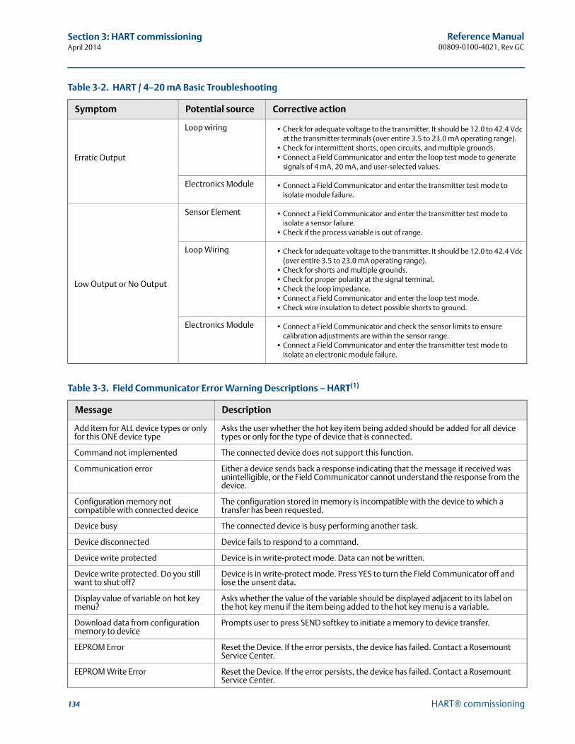
134
Reference Manual00809-0100-4021, Rev GC
Section 3: HART commissioningApril 2014
HART® commissioning
Erratic Output
Loop wiring • Check for adequate voltage to the transmitter. It should be 12.0 to 42.4 Vdc at the transmitter terminals (over entire 3.5 to 23.0 mA operating range).
• Check for intermittent shorts, open circuits, and multiple grounds.• Connect a Field Communicator and enter the loop test mode to generate
signals of 4 mA, 20 mA, and user-selected values.
Electronics Module • Connect a Field Communicator and enter the transmitter test mode to isolate module failure.
Low Output or No Output
Sensor Element • Connect a Field Communicator and enter the transmitter test mode to isolate a sensor failure.
• Check if the process variable is out of range.
Loop Wiring • Check for adequate voltage to the transmitter. It should be 12.0 to 42.4 Vdc (over entire 3.5 to 23.0 mA operating range).
• Check for shorts and multiple grounds. • Check for proper polarity at the signal terminal.• Check the loop impedance.• Connect a Field Communicator and enter the loop test mode.• Check wire insulation to detect possible shorts to ground.
Electronics Module • Connect a Field Communicator and check the sensor limits to ensure calibration adjustments are within the sensor range.
• Connect a Field Communicator and enter the transmitter test mode to isolate an electronic module failure.
Table 3-3. Field Communicator Error Warning Descriptions – HART(1)
Message Description
Add item for ALL device types or only for this ONE device type
Asks the user whether the hot key item being added should be added for all device types or only for the type of device that is connected.
Command not implemented The connected device does not support this function.
Communication error Either a device sends back a response indicating that the message it received was unintelligible, or the Field Communicator cannot understand the response from the device.
Configuration memory not compatible with connected device
The configuration stored in memory is incompatible with the device to which a transfer has been requested.
Device busy The connected device is busy performing another task.
Device disconnected Device fails to respond to a command.
Device write protected Device is in write-protect mode. Data can not be written.
Device write protected. Do you still want to shut off?
Device is in write-protect mode. Press YES to turn the Field Communicator off and lose the unsent data.
Display value of variable on hot key menu?
Asks whether the value of the variable should be displayed adjacent to its label on the hot key menu if the item being added to the hot key menu is a variable.
Download data from configuration memory to device
Prompts user to press SEND softkey to initiate a memory to device transfer.
EEPROM Error Reset the Device. If the error persists, the device has failed. Contact a Rosemount Service Center.
EEPROM Write Error Reset the Device. If the error persists, the device has failed. Contact a Rosemount Service Center.
Table 3-2. HART / 4–20 mA Basic Troubleshooting
Symptom Potential source Corrective action
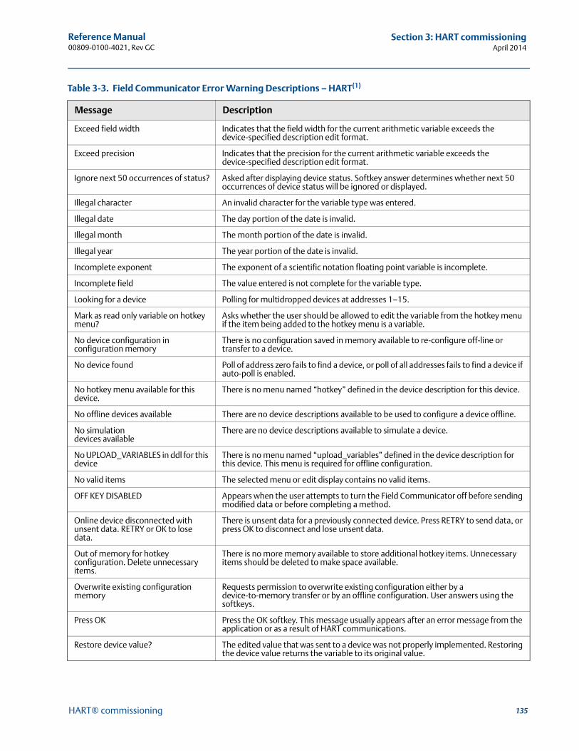
135
Reference Manual 00809-0100-4021, Rev GC
Section 3: HART commissioningApril 2014
HART® commissioning
Exceed field width Indicates that the field width for the current arithmetic variable exceeds the device-specified description edit format.
Exceed precision Indicates that the precision for the current arithmetic variable exceeds the device-specified description edit format.
Ignore next 50 occurrences of status? Asked after displaying device status. Softkey answer determines whether next 50 occurrences of device status will be ignored or displayed.
Illegal character An invalid character for the variable type was entered.
Illegal date The day portion of the date is invalid.
Illegal month The month portion of the date is invalid.
Illegal year The year portion of the date is invalid.
Incomplete exponent The exponent of a scientific notation floating point variable is incomplete.
Incomplete field The value entered is not complete for the variable type.
Looking for a device Polling for multidropped devices at addresses 1–15.
Mark as read only variable on hotkey menu?
Asks whether the user should be allowed to edit the variable from the hotkey menu if the item being added to the hotkey menu is a variable.
No device configuration in configuration memory
There is no configuration saved in memory available to re-configure off-line or transfer to a device.
No device found Poll of address zero fails to find a device, or poll of all addresses fails to find a device if auto-poll is enabled.
No hotkey menu available for this device.
There is no menu named “hotkey” defined in the device description for this device.
No offline devices available There are no device descriptions available to be used to configure a device offline.
No simulation devices available
There are no device descriptions available to simulate a device.
No UPLOAD_VARIABLES in ddl for this device
There is no menu named “upload_variables” defined in the device description for this device. This menu is required for offline configuration.
No valid items The selected menu or edit display contains no valid items.
OFF KEY DISABLED Appears when the user attempts to turn the Field Communicator off before sending modified data or before completing a method.
Online device disconnected with unsent data. RETRY or OK to lose data.
There is unsent data for a previously connected device. Press RETRY to send data, or press OK to disconnect and lose unsent data.
Out of memory for hotkey configuration. Delete unnecessary items.
There is no more memory available to store additional hotkey items. Unnecessary items should be deleted to make space available.
Overwrite existing configuration memory
Requests permission to overwrite existing configuration either by a device-to-memory transfer or by an offline configuration. User answers using the softkeys.
Press OK Press the OK softkey. This message usually appears after an error message from the application or as a result of HART communications.
Restore device value? The edited value that was sent to a device was not properly implemented. Restoring the device value returns the variable to its original value.
Table 3-3. Field Communicator Error Warning Descriptions – HART(1)
Message Description
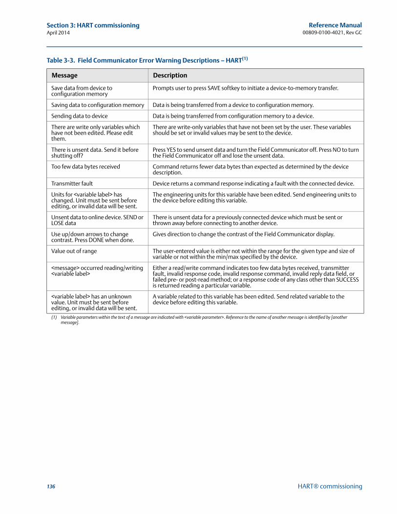
136
Reference Manual00809-0100-4021, Rev GC
Section 3: HART commissioningApril 2014
HART® commissioning
Save data from device to configuration memory
Prompts user to press SAVE softkey to initiate a device-to-memory transfer.
Saving data to configuration memory Data is being transferred from a device to configuration memory.
Sending data to device Data is being transferred from configuration memory to a device.
There are write only variables which have not been edited. Please edit them.
There are write-only variables that have not been set by the user. These variables should be set or invalid values may be sent to the device.
There is unsent data. Send it before shutting off?
Press YES to send unsent data and turn the Field Communicator off. Press NO to turn the Field Communicator off and lose the unsent data.
Too few data bytes received Command returns fewer data bytes than expected as determined by the device description.
Transmitter fault Device returns a command response indicating a fault with the connected device.
Units for <variable label> has changed. Unit must be sent before editing, or invalid data will be sent.
The engineering units for this variable have been edited. Send engineering units to the device before editing this variable.
Unsent data to online device. SEND or LOSE data
There is unsent data for a previously connected device which must be sent or thrown away before connecting to another device.
Use up/down arrows to change contrast. Press DONE when done.
Gives direction to change the contrast of the Field Communicator display.
Value out of range The user-entered value is either not within the range for the given type and size of variable or not within the min/max specified by the device.
<message> occurred reading/writing <variable label>
Either a read/write command indicates too few data bytes received, transmitter fault, invalid response code, invalid response command, invalid reply data field, or failed pre- or post-read method; or a response code of any class other than SUCCESS is returned reading a particular variable.
<variable label> has an unknown value. Unit must be sent before editing, or invalid data will be sent.
A variable related to this variable has been edited. Send related variable to the device before editing this variable.
(1) Variable parameters within the text of a message are indicated with <variable parameter>. Reference to the name of another message is identified by [another message].
Table 3-3. Field Communicator Error Warning Descriptions – HART(1)
Message Description
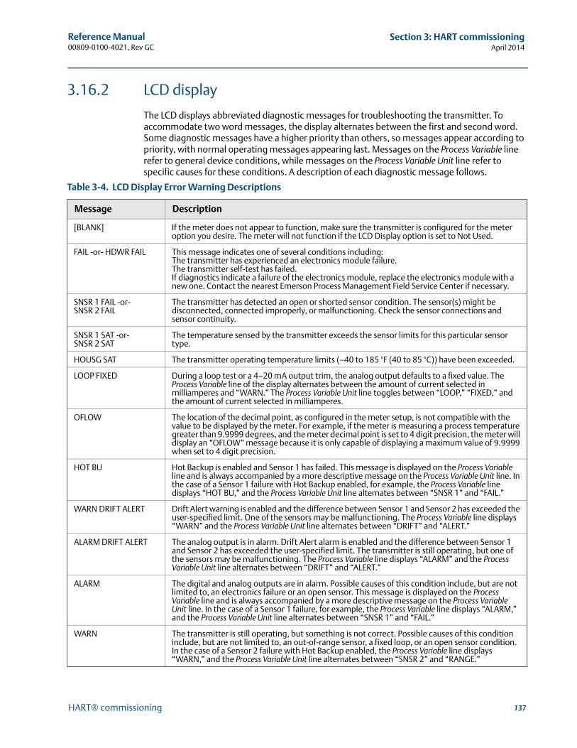
137
Reference Manual 00809-0100-4021, Rev GC
Section 3: HART commissioningApril 2014
HART® commissioning
3.16.2 LCD display
The LCD displays abbreviated diagnostic messages for troubleshooting the transmitter. To accommodate two word messages, the display alternates between the first and second word. Some diagnostic messages have a higher priority than others, so messages appear according to priority, with normal operating messages appearing last. Messages on the Process Variable line refer to general device conditions, while messages on the Process Variable Unit line refer to specific causes for these conditions. A description of each diagnostic message follows.
Table 3-4. LCD Display Error Warning Descriptions
Message Description
[BLANK] If the meter does not appear to function, make sure the transmitter is configured for the meter option you desire. The meter will not function if the LCD Display option is set to Not Used.
FAIL -or- HDWR FAIL This message indicates one of several conditions including:The transmitter has experienced an electronics module failure.The transmitter self-test has failed.If diagnostics indicate a failure of the electronics module, replace the electronics module with a new one. Contact the nearest Emerson Process Management Field Service Center if necessary.
SNSR 1 FAIL -or- SNSR 2 FAIL
The transmitter has detected an open or shorted sensor condition. The sensor(s) might be disconnected, connected improperly, or malfunctioning. Check the sensor connections and sensor continuity.
SNSR 1 SAT -or- SNSR 2 SAT
The temperature sensed by the transmitter exceeds the sensor limits for this particular sensor type.
HOUSG SAT The transmitter operating temperature limits (–40 to 185 °F (40 to 85 °C)) have been exceeded.
LOOP FIXED During a loop test or a 4–20 mA output trim, the analog output defaults to a fixed value. The Process Variable line of the display alternates between the amount of current selected in milliamperes and “WARN.” The Process Variable Unit line toggles between “LOOP,” “FIXED,” and the amount of current selected in milliamperes.
OFLOW The location of the decimal point, as configured in the meter setup, is not compatible with the value to be displayed by the meter. For example, if the meter is measuring a process temperature greater than 9.9999 degrees, and the meter decimal point is set to 4 digit precision, the meter will display an “OFLOW” message because it is only capable of displaying a maximum value of 9.9999 when set to 4 digit precision.
HOT BU Hot Backup is enabled and Sensor 1 has failed. This message is displayed on the Process Variable line and is always accompanied by a more descriptive message on the Process Variable Unit line. In the case of a Sensor 1 failure with Hot Backup enabled, for example, the Process Variable line displays “HOT BU,” and the Process Variable Unit line alternates between “SNSR 1” and “FAIL.”
WARN DRIFT ALERT Drift Alert warning is enabled and the difference between Sensor 1 and Sensor 2 has exceeded the user-specified limit. One of the sensors may be malfunctioning. The Process Variable line displays “WARN” and the Process Variable Unit line alternates between “DRIFT” and “ALERT.”
ALARM DRIFT ALERT The analog output is in alarm. Drift Alert alarm is enabled and the difference between Sensor 1 and Sensor 2 has exceeded the user-specified limit. The transmitter is still operating, but one of the sensors may be malfunctioning. The Process Variable line displays “ALARM” and the Process Variable Unit line alternates between “DRIFT” and “ALERT.”
ALARM The digital and analog outputs are in alarm. Possible causes of this condition include, but are not limited to, an electronics failure or an open sensor. This message is displayed on the Process Variable line and is always accompanied by a more descriptive message on the Process Variable Unit line. In the case of a Sensor 1 failure, for example, the Process Variable line displays “ALARM,” and the Process Variable Unit line alternates between “SNSR 1” and “FAIL.”
WARN The transmitter is still operating, but something is not correct. Possible causes of this condition include, but are not limited to, an out-of-range sensor, a fixed loop, or an open sensor condition. In the case of a Sensor 2 failure with Hot Backup enabled, the Process Variable line displays “WARN,” and the Process Variable Unit line alternates between “SNSR 2” and “RANGE.”

138
Reference Manual00809-0100-4021, Rev GC
Section 3: HART commissioningApril 2014
HART® commissioning
3.16.3 Spare parts
This spare part is available for the 3144P Transmitter.
Description Part number
Replacement electronics module assembly 03144-3111-0001
Reference Manual 00809-0100-4021, Rev GC
Section 4: FOUNDATION fieldbus ConfigurationApril 2014
139Foundation™ fieldbus configuration
Section 4 FOUNDATION™ fieldbus configuration
Overview . . . . . . . . . . . . . . . . . . . . . . . . . . . . . . . . . . . . . . . . . . . . . . . . . . . . . . . . . . . . . . . . . . page 139Safety messages . . . . . . . . . . . . . . . . . . . . . . . . . . . . . . . . . . . . . . . . . . . . . . . . . . . . . . . . . . . . page 139General block information . . . . . . . . . . . . . . . . . . . . . . . . . . . . . . . . . . . . . . . . . . . . . . . . . . . page 140Foundation fieldbus function blocks . . . . . . . . . . . . . . . . . . . . . . . . . . . . . . . . . . . . . . . . . . . page 142Resource block . . . . . . . . . . . . . . . . . . . . . . . . . . . . . . . . . . . . . . . . . . . . . . . . . . . . . . . . . . . . . page 144Sensor transducer block . . . . . . . . . . . . . . . . . . . . . . . . . . . . . . . . . . . . . . . . . . . . . . . . . . . . . page 150LCD display transducer block . . . . . . . . . . . . . . . . . . . . . . . . . . . . . . . . . . . . . . . . . . . . . . . . . page 152Analog Input (AI) . . . . . . . . . . . . . . . . . . . . . . . . . . . . . . . . . . . . . . . . . . . . . . . . . . . . . . . . . . . page 155Operation . . . . . . . . . . . . . . . . . . . . . . . . . . . . . . . . . . . . . . . . . . . . . . . . . . . . . . . . . . . . . . . . . . page 162Troubleshooting guides . . . . . . . . . . . . . . . . . . . . . . . . . . . . . . . . . . . . . . . . . . . . . . . . . . . . . . page 168
4.1 OverviewThis section provides information on configuring, troubleshooting, operating, and maintaining the Rosemount® 3144P transmitter using FOUNDATION fieldbus protocol. There are many common attributes with the HART® transmitter, and if the information cannot be found in this section, refer to Section 3: HART® commissioning.
4.2 Safety messagesInstructions and procedures in this section may require special precautions to ensure the safety of the personnel performing the operations. Information that potentially raises safety issues is indicated by a warning symbol ( ). Please refer to the following safety messages before performing an operation preceded by this symbol.
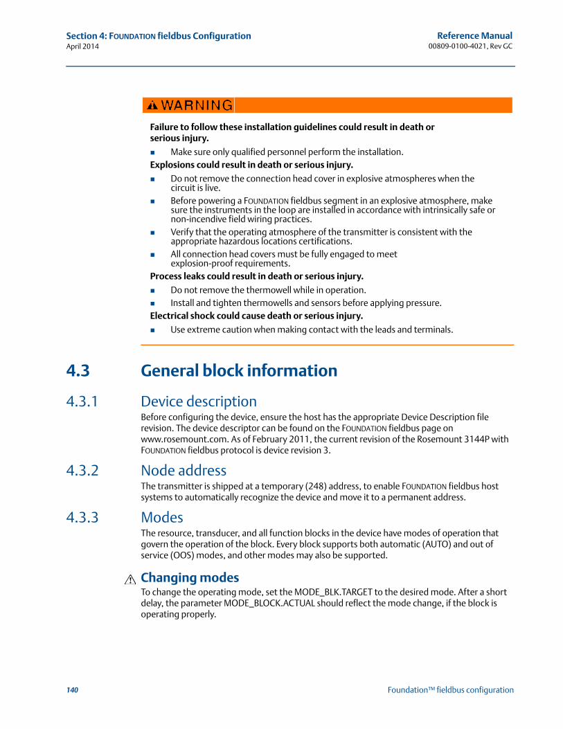
140
Reference Manual00809-0100-4021, Rev GC
Section 4: FOUNDATION fieldbus ConfigurationApril 2014
Foundation™ fieldbus configuration
4.3 General block information
4.3.1 Device descriptionBefore configuring the device, ensure the host has the appropriate Device Description file revision. The device descriptor can be found on the FOUNDATION fieldbus page on www.rosemount.com. As of February 2011, the current revision of the Rosemount 3144P with FOUNDATION fieldbus protocol is device revision 3.
4.3.2 Node addressThe transmitter is shipped at a temporary (248) address, to enable FOUNDATION fieldbus host systems to automatically recognize the device and move it to a permanent address.
4.3.3 ModesThe resource, transducer, and all function blocks in the device have modes of operation that govern the operation of the block. Every block supports both automatic (AUTO) and out of service (OOS) modes, and other modes may also be supported.
Changing modesTo change the operating mode, set the MODE_BLK.TARGET to the desired mode. After a short delay, the parameter MODE_BLOCK.ACTUAL should reflect the mode change, if the block is operating properly.
Failure to follow these installation guidelines could result in death orserious injury.
Make sure only qualified personnel perform the installation.Explosions could result in death or serious injury.
Do not remove the connection head cover in explosive atmospheres when the circuit is live.
Before powering a FOUNDATION fieldbus segment in an explosive atmosphere, make sure the instruments in the loop are installed in accordance with intrinsically safe or non-incendive field wiring practices.
Verify that the operating atmosphere of the transmitter is consistent with the appropriate hazardous locations certifications.
All connection head covers must be fully engaged to meet explosion-proof requirements.
Process leaks could result in death or serious injury.
Do not remove the thermowell while in operation. Install and tighten thermowells and sensors before applying pressure.Electrical shock could cause death or serious injury.
Use extreme caution when making contact with the leads and terminals.
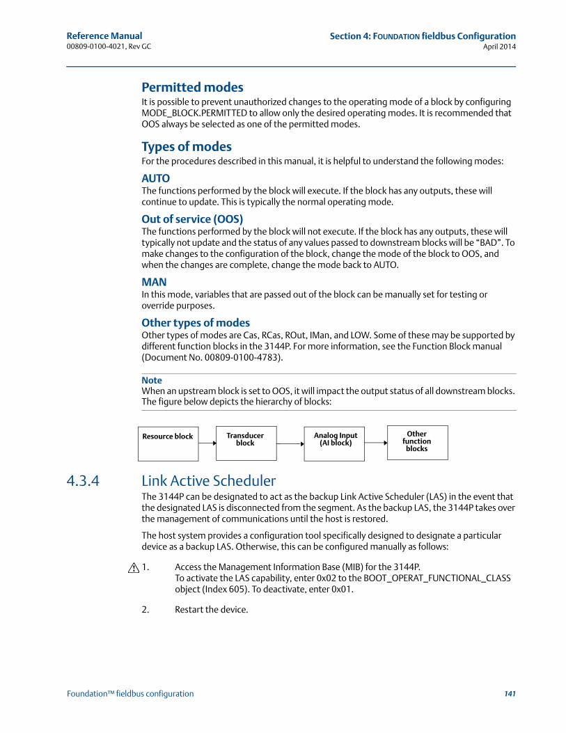
141
Reference Manual 00809-0100-4021, Rev GC
Section 4: FOUNDATION fieldbus ConfigurationApril 2014
Foundation™ fieldbus configuration
Permitted modesIt is possible to prevent unauthorized changes to the operating mode of a block by configuring MODE_BLOCK.PERMITTED to allow only the desired operating modes. It is recommended that OOS always be selected as one of the permitted modes.
Types of modesFor the procedures described in this manual, it is helpful to understand the following modes:
AUTOThe functions performed by the block will execute. If the block has any outputs, these will continue to update. This is typically the normal operating mode.
Out of service (OOS)The functions performed by the block will not execute. If the block has any outputs, these will typically not update and the status of any values passed to downstream blocks will be “BAD”. To make changes to the configuration of the block, change the mode of the block to OOS, and when the changes are complete, change the mode back to AUTO.
MANIn this mode, variables that are passed out of the block can be manually set for testing or override purposes.
Other types of modesOther types of modes are Cas, RCas, ROut, IMan, and LOW. Some of these may be supported by different function blocks in the 3144P. For more information, see the Function Block manual (Document No. 00809-0100-4783).
NoteWhen an upstream block is set to OOS, it will impact the output status of all downstream blocks. The figure below depicts the hierarchy of blocks:
4.3.4 Link Active SchedulerThe 3144P can be designated to act as the backup Link Active Scheduler (LAS) in the event that the designated LAS is disconnected from the segment. As the backup LAS, the 3144P takes over the management of communications until the host is restored.
The host system provides a configuration tool specifically designed to designate a particular device as a backup LAS. Otherwise, this can be configured manually as follows:
1. Access the Management Information Base (MIB) for the 3144P.To activate the LAS capability, enter 0x02 to the BOOT_OPERAT_FUNCTIONAL_CLASS object (Index 605). To deactivate, enter 0x01.
2. Restart the device.
Resource block Transducer block
Analog Input (AI block)
Other function
blocks
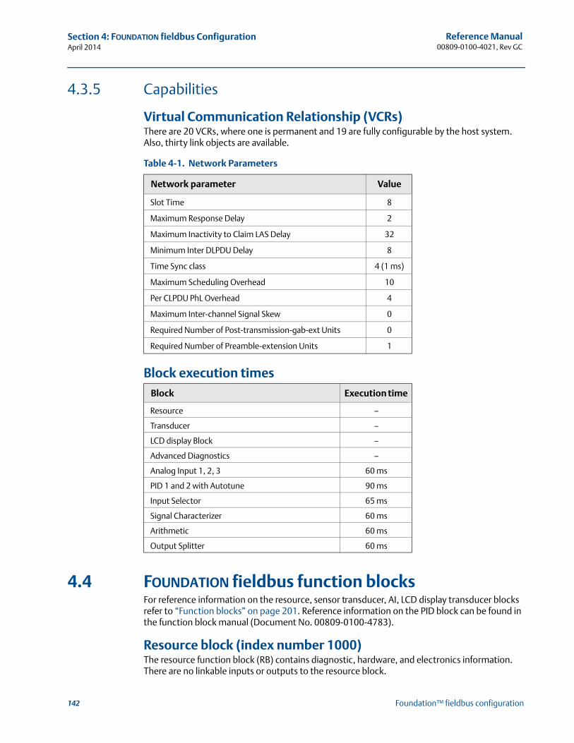
142
Reference Manual00809-0100-4021, Rev GC
Section 4: FOUNDATION fieldbus ConfigurationApril 2014
Foundation™ fieldbus configuration
4.3.5 Capabilities
Virtual Communication Relationship (VCRs) There are 20 VCRs, where one is permanent and 19 are fully configurable by the host system. Also, thirty link objects are available.
Table 4-1. Network Parameters
Block execution times
4.4 FOUNDATION fieldbus function blocks For reference information on the resource, sensor transducer, AI, LCD display transducer blocks refer to “Function blocks” on page 201. Reference information on the PID block can be found in the function block manual (Document No. 00809-0100-4783).
Resource block (index number 1000)The resource function block (RB) contains diagnostic, hardware, and electronics information. There are no linkable inputs or outputs to the resource block.
Network parameter Value
Slot Time 8
Maximum Response Delay 2
Maximum Inactivity to Claim LAS Delay 32
Minimum Inter DLPDU Delay 8
Time Sync class 4 (1 ms)
Maximum Scheduling Overhead 10
Per CLPDU PhL Overhead 4
Maximum Inter-channel Signal Skew 0
Required Number of Post-transmission-gab-ext Units 0
Required Number of Preamble-extension Units 1
Block Execution time
Resource –
Transducer –
LCD display Block –
Advanced Diagnostics –
Analog Input 1, 2, 3 60 ms
PID 1 and 2 with Autotune 90 ms
Input Selector 65 ms
Signal Characterizer 60 ms
Arithmetic 60 ms
Output Splitter 60 ms

143
Reference Manual 00809-0100-4021, Rev GC
Section 4: FOUNDATION fieldbus ConfigurationApril 2014
Foundation™ fieldbus configuration
Sensor transducer block (index number 1100)The Sensor Transducer Function Block (STB) temperature measurement data, includes sensor and terminal (body) temperature. The STB also includes information about sensor type, engineering units, linearization, reranging, damping, temperature compensation, and diagnostics. Transmitter Revision 3 and above also contain Hot Backup™ functionality in the STB.
LCD display transducer block (index number 1200)The LCD display transducer block is used to configure the LCD display.
Analog input block (index number 1400, 1500, 1600, and 1700)The Analog Input Function Block (AI) processes the measurements from the sensor and makes them available to other function blocks. The output value from the AI block is in engineering units and contains a status indicating the quality of the measurement. The AI block is used for scaling functionality.
PID block (index number 1800 and 1900)The PID function block combines all of the necessary logic to perform proportional/inte-gral/derivative (PID) control. The block supports mode control, signal scaling and limiting, feed forward control, override tracking, alarm limit detection, and signal status propagation.
The block supports two forms of the PID equation: Standard and Series. Choose the appropriate equation using the MATHFORM parameter. The Standard ISA PID equation is the default selection and autotune.
Input selector (index number 2000)The signal selector block provides selection of up to four inputs and generates an output based on the configured action. This block normally receives its inputs from AI blocks. The block performs maximum, minimum, middle, average, and ‘first good’ signal selection.
Output splitter (index number OSPL 2300)The output splitter block provides the capability to drive two control outputs from a single input. Each output is a linear function of some portion of the input.
Arithmetic (index number 2200)This block is designed to permit simple use of popular measurement math functions. The user does not have to know how to write equations. The math algorithm is selected by name, chosen by the user for the function to be done.
Signal characterizer (index number 2100)The signal characterizer block has two sections, each with an output that is a non-linear function of the respective input. The non-linear function is determined by a single look-up table with 21 arbitrary x-y pairs. The status of an input is copied to the corresponding output, so the block may be used in the control or process signal path.
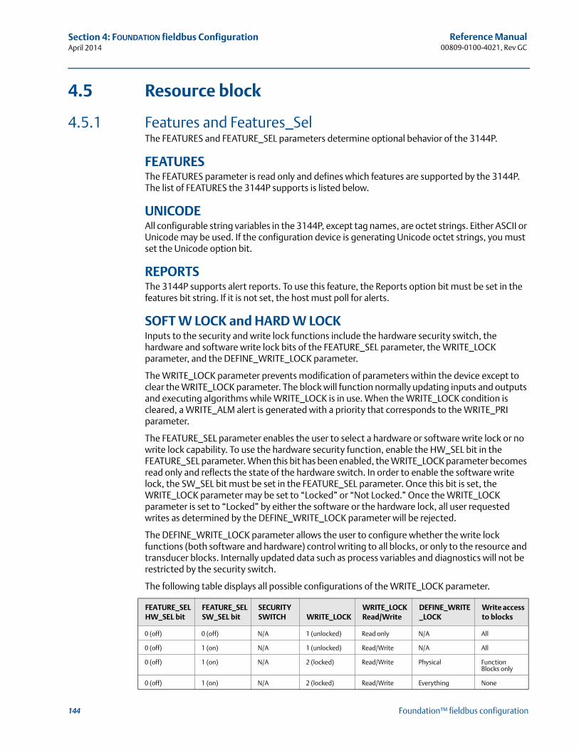
144
Reference Manual00809-0100-4021, Rev GC
Section 4: FOUNDATION fieldbus ConfigurationApril 2014
Foundation™ fieldbus configuration
4.5 Resource block
4.5.1 Features and Features_SelThe FEATURES and FEATURE_SEL parameters determine optional behavior of the 3144P.
FEATURESThe FEATURES parameter is read only and defines which features are supported by the 3144P. The list of FEATURES the 3144P supports is listed below.
UNICODEAll configurable string variables in the 3144P, except tag names, are octet strings. Either ASCII or Unicode may be used. If the configuration device is generating Unicode octet strings, you must set the Unicode option bit.
REPORTSThe 3144P supports alert reports. To use this feature, the Reports option bit must be set in the features bit string. If it is not set, the host must poll for alerts.
SOFT W LOCK and HARD W LOCKInputs to the security and write lock functions include the hardware security switch, the hardware and software write lock bits of the FEATURE_SEL parameter, the WRITE_LOCK parameter, and the DEFINE_WRITE_LOCK parameter.
The WRITE_LOCK parameter prevents modification of parameters within the device except to clear the WRITE_LOCK parameter. The block will function normally updating inputs and outputs and executing algorithms while WRITE_LOCK is in use. When the WRITE_LOCK condition is cleared, a WRITE_ALM alert is generated with a priority that corresponds to the WRITE_PRI parameter.
The FEATURE_SEL parameter enables the user to select a hardware or software write lock or no write lock capability. To use the hardware security function, enable the HW_SEL bit in the FEATURE_SEL parameter. When this bit has been enabled, the WRITE_LOCK parameter becomes read only and reflects the state of the hardware switch. In order to enable the software write lock, the SW_SEL bit must be set in the FEATURE_SEL parameter. Once this bit is set, the WRITE_LOCK parameter may be set to “Locked” or “Not Locked.” Once the WRITE_LOCK parameter is set to “Locked” by either the software or the hardware lock, all user requested writes as determined by the DEFINE_WRITE_LOCK parameter will be rejected.
The DEFINE_WRITE_LOCK parameter allows the user to configure whether the write lock functions (both software and hardware) control writing to all blocks, or only to the resource and transducer blocks. Internally updated data such as process variables and diagnostics will not be restricted by the security switch.
The following table displays all possible configurations of the WRITE_LOCK parameter.
FEATURE_SELHW_SEL bit
FEATURE_SEL SW_SEL bit
SECURITY SWITCH WRITE_LOCK
WRITE_LOCK Read/Write
DEFINE_WRITE_LOCK
Write access to blocks
0 (off) 0 (off) N/A 1 (unlocked) Read only N/A All
0 (off) 1 (on) N/A 1 (unlocked) Read/Write N/A All
0 (off) 1 (on) N/A 2 (locked) Read/Write Physical Function Blocks only
0 (off) 1 (on) N/A 2 (locked) Read/Write Everything None
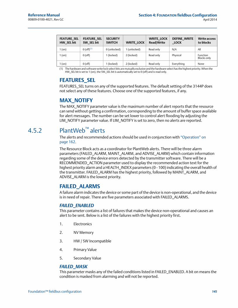
145
Reference Manual 00809-0100-4021, Rev GC
Section 4: FOUNDATION fieldbus ConfigurationApril 2014
Foundation™ fieldbus configuration
FEATURES_SELFEATURES_SEL turns on any of the supported features. The default setting of the 3144P does not select any of these features. Choose one of the supported features, if any.
MAX_NOTIFYThe MAX_NOTIFY parameter value is the maximum number of alert reports that the resource can send without getting a confirmation, corresponding to the amount of buffer space available for alert messages. The number can be set lower to control alert flooding by adjusting the LIM_NOTIFY parameter value. If LIM_NOTIFY is set to zero, then no alerts are reported.
4.5.2 PlantWeb™ alertsThe alerts and recommended actions should be used in conjunction with “Operation” on page 162.
The Resource Block acts as a coordinator for PlantWeb alerts. There will be three alarm parameters (FAILED_ALARM, MAINT_ALARM, and ADVISE_ALARM) which contain information regarding some of the device errors detected by the transmitter software. There will be a RECOMMENDED_ACTION parameter used to display the recommended action text for the highest priority alarm and a HEALTH_INDEX parameters (0 - 100) indicating the overall health of the transmitter. FAILED_ALARM has the highest priority, followed by MAINT_ALARM, and ADVISE_ALARM is the lowest priority.
FAILED_ALARMSA failure alarm indicates the device or some part of the device is non-operational, and the device is in need of repair. There are five parameters associated with FAILED_ALARMS.
FAILED_ENABLEDThis parameter contains a list of failures that makes the device non-operational and causes an alert to be sent. Below is a list of the failures with the highest priority first.
1. Electronics
2. NV Memory
3. HW / SW Incompatible
4. Primary Value
5. Secondary Value
FAILED_MASKThis parameter masks any of the failed conditions listed in FAILED_ENABLED. A bit on means the condition is masked from alarming and will not be reported.
1 (on) 0 (off)(1) 0 (unlocked) 1 (unlocked) Read only N/A All
1 (on) 0 (off) 1 (locked) 2 (locked) Read only Physical Function Blocks only
1 (on) 0 (off) 1 (locked) 2 (locked) Read only Everything None
(1) The hardware and software write lock select bits are mutually exclusive and the hardware select has the highest priority. When the HW_SEL bit is set to 1 (on), the SW_SEL bit is automatically set to 0 (off) and is read only.
FEATURE_SELHW_SEL bit
FEATURE_SEL SW_SEL bit
SECURITY SWITCH WRITE_LOCK
WRITE_LOCK Read/Write
DEFINE_WRITE_LOCK
Write access to blocks
146
Reference Manual00809-0100-4021, Rev GC
Section 4: FOUNDATION fieldbus ConfigurationApril 2014
Foundation™ fieldbus configuration
FAILED_PRIDesignates the alerting priority of the FAILED_ALM, see “Alarm priority” on page 159. The default is 0, and the recommended values are between 8 and 15.
FAILED_ACTIVEThis parameter displays the active alarms. Only the highest priority alarm will be displayed. This priority is not the same as the FAILED_PRI parameter described above, but is hard coded within the device and is not user configurable.
FAILED_ALMAlarm indicating a failure within a device which makes the device non-operational.
MAINT_ALARMSA maintenance alarm indicates the device, or some part of the device, needs maintenance soon. If the condition is ignored, the device will eventually fail. There are five parameters associated with MAINT_ALARMS:
MAINT_ENABLEDThe MAINT_ENABLED parameter contains a list of conditions indicating the device, or some part of the device, needs maintenance soon.
Below is a list of the conditions, with the highest priority first.
1. Primary Value Degraded
2. Secondary Value Degraded
3. Configuration Error
4. Calibration Error
MAINT_MASKThe MAINT_MASK parameter masks any of the failed conditions listed in MAINT_ENABLED. A bit on means that the condition is masked out from alarming and will not be reported.
MAINT_PRIMAINT_PRI designates the alarming priority of the MAINT_ALM, see “Process alarms” on page 159. The default is 0 and the recommended values is 3 to 7.
MAINT_ACTIVEThe MAINT_ACTIVE parameter displays which of the alarms is active. Only the condition with the highest priority will be displayed. This priority is not the same as the MAINT_PRI parameter described above. This priority is hard coded within the device and is not user configurable.
MAINT_ALMAn alarm indicating the device needs maintenance soon. If the condition is ignored, the device will eventually fail.
Advisory alarmsAn advisory alarm indicates informative conditions that do not have a direct impact on the device's primary functions. There are five parameters associated with ADVISE_ALARMS. They are described below.
147
Reference Manual 00809-0100-4021, Rev GC
Section 4: FOUNDATION fieldbus ConfigurationApril 2014
Foundation™ fieldbus configuration
ADVISE_ENABLEDThe ADVISE_ENABLED parameter contains a list of informative conditions that do not have a direct impact on the device's primary functions. Below is a list of the advisories with the highest priority first.
1. NV Writes Deferred
2. SPM Process Anomaly detected
ADVISE_MASKThe ADVISE_MASK parameter will mask any of the failed conditions listed in ADVISE_ENABLED. A bit on means the condition is masked from alarming and will not be reported.
ADVISE_PRIADVISE_PRI designates the alarming priority of the ADVISE_ALM, see “Process alarms” on page 159. The default is 0, and the recommended values are 1 or 2.
ADVISE_ACTIVEThe ADVISE_ACTIVE parameter displays the active advisories. Only the advisory with the highest priority is displayed. This priority is not the same as the ADVISE_PRI parameter described above, but is hard coded within the device and is not user configurable.
ADVISE_ALMADVISE_ALM indicates advisory alarms. These conditions do not have a direct impact on the process or device integrity.
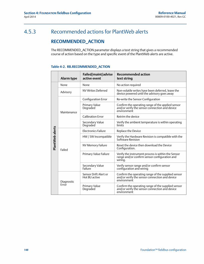
148
Reference Manual00809-0100-4021, Rev GC
Section 4: FOUNDATION fieldbus ConfigurationApril 2014
Foundation™ fieldbus configuration
4.5.3 Recommended actions for PlantWeb alerts
RECOMMENDED_ACTION
The RECOMMENDED_ACTION parameter displays a text string that gives a recommended course of action based on the type and specific event of the PlantWeb alerts are active.
Table 4-2. RB.RECOMMENDED_ACTION
Alarm typeFailed/maint/adviseactive event
Recommended action text string
Plan
tWeb
ale
rts
None None No action required
Advisory NV Writes Deferred Non-volatile writes have been deferred, leave the device powered until the advisory goes away
Maintenance
Configuration Error Re-write the Sensor Configuration
Primary Value Degraded
Confirm the operating range of the applied sensor and/or verify the sensor connection and device environment
Calibration Error Retrim the device
Secondary Value Degraded
Verify the ambient temperature is within operating limits
Failed
Electronics Failure Replace the Device
HW / SW Incompatible Verify the Hardware Revision is compatible with the Software Revision
NV Memory Failure Reset the device then download the Device Configuration.
Primary Value Failure Verify the instrument process is within the Sensor range and/or confirm sensor configuration and wiring.
Secondary Value Failure
Verify sensor range and/or confirm sensor configuration and wiring
Diagnostic Error
Sensor Drift Alert or Hot BU active
Confirm the operating range of the supplied sensor and/or verify the sensor connection and device environment
Primary Value Degraded
Confirm the operating range of the supplied sensor and/or verify the sensor connection and device environment
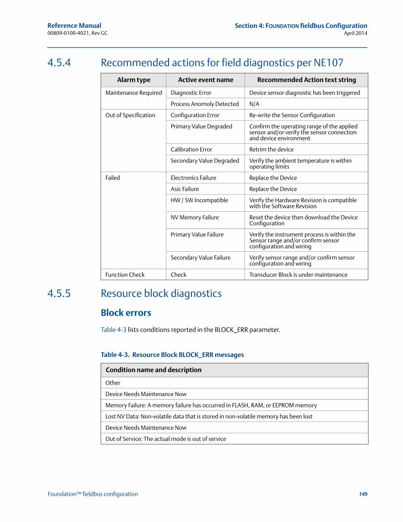
149
Reference Manual 00809-0100-4021, Rev GC
Section 4: FOUNDATION fieldbus ConfigurationApril 2014
Foundation™ fieldbus configuration
4.5.4 Recommended actions for field diagnostics per NE107
4.5.5 Resource block diagnostics
Block errors
Table 4-3 lists conditions reported in the BLOCK_ERR parameter.
Alarm type Active event name Recommended Action text string
Maintenance Required Diagnostic Error Device sensor diagnostic has been triggered
Process Anomoly Detected N/A
Out of Specification Configuration Error Re-write the Sensor Configuration
Primary Value Degraded Confirm the operating range of the applied sensor and/or verify the sensor connection and device environment
Calibration Error Retrim the device
Secondary Value Degraded Verify the ambient temperature is within operating limits
Failed Electronics Failure Replace the Device
Asic Failure Replace the Device
HW / SW Incompatible Verify the Hardware Revision is compatible with the Software Revision
NV Memory Failure Reset the device then download the Device Configuration
Primary Value Failure Verify the instrument process is within the Sensor range and/or confirm sensor configuration and wiring
Secondary Value Failure Verify sensor range and/or confirm sensor configuration and wiring
Function Check Check Transducer Block is under maintenance
Table 4-3. Resource Block BLOCK_ERR messages
Condition name and description
Other
Device Needs Maintenance Now
Memory Failure: A memory failure has occurred in FLASH, RAM, or EEPROM memory
Lost NV Data: Non-volatile data that is stored in non-volatile memory has been lost
Device Needs Maintenance Now
Out of Service: The actual mode is out of service
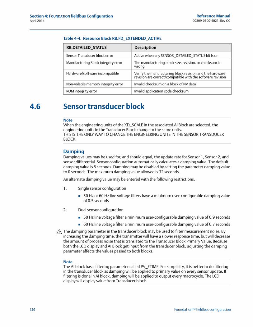
150
Reference Manual00809-0100-4021, Rev GC
Section 4: FOUNDATION fieldbus ConfigurationApril 2014
Foundation™ fieldbus configuration
Table 4-4. Resource Block RB.FD_EXTENDED_ACTIVE
4.6 Sensor transducer block
NoteWhen the engineering units of the XD_SCALE in the associated AI Block are selected, the engineering units in the Transducer Block change to the same units. THIS IS THE ONLY WAY TO CHANGE THE ENGINEERING UNITS IN THE SENSOR TRANSDUCER BLOCK.
DampingDamping values may be used for, and should equal, the update rate for Sensor 1, Sensor 2, and sensor differential. Sensor configuration automatically calculates a damping value. The default damping value is 5 seconds. Damping may be disabled by setting the parameter damping value to 0 seconds. The maximum damping value allowed is 32 seconds.
An alternate damping value may be entered with the following restrictions.
1. Single sensor configuration
50 Hz or 60 Hz line voltage filters have a minimum user-configurable damping value of 0.5 seconds
2. Dual sensor configuration
50 Hz line voltage filter a minimum user-configurable damping value of 0.9 seconds
60 Hz line voltage filter a minimum user-configurable damping value of 0.7 seconds
The damping parameter in the transducer block may be used to filter measurement noise. By increasing the damping time, the transmitter will have a slower response time, but will decrease the amount of process noise that is translated to the Transducer Block Primary Value. Because both the LCD display and AI Block get input from the transducer block, adjusting the damping parameter affects the values passed to both blocks.
NoteThe AI block has a filtering parameter called PV_FTIME. For simplicity, it is better to do filtering in the transducer block as damping will be applied to primary value on every sensor update. If filtering is done in AI block, damping will be applied to output every macrocycle. The LCD display will display value from Transducer block.
RB.DETAILED_STATUS Description
Sensor Transducer block error Active when any SENSOR_DETAILED_STATUS bit is on
Manufacturing Block integrity error The manufacturing block size, revision, or checksum is wrong
Hardware/software incompatible Verify the manufacturing block revision and the hardware revision are correct/compatible with the software revision
Non-volatile memory integrity error Invalid checksum on a block of NV data
ROM integrity error Invalid application code checksum
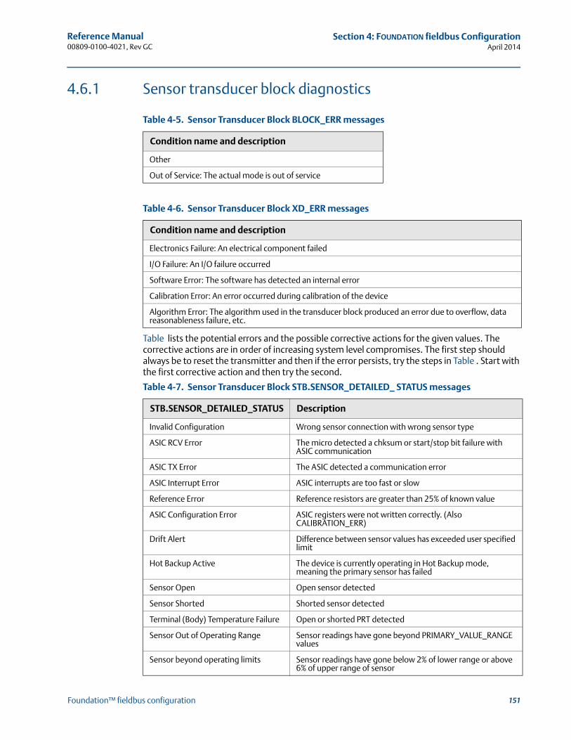
151
Reference Manual 00809-0100-4021, Rev GC
Section 4: FOUNDATION fieldbus ConfigurationApril 2014
Foundation™ fieldbus configuration
4.6.1 Sensor transducer block diagnostics
Table lists the potential errors and the possible corrective actions for the given values. The corrective actions are in order of increasing system level compromises. The first step should always be to reset the transmitter and then if the error persists, try the steps in Table . Start with the first corrective action and then try the second.
Table 4-5. Sensor Transducer Block BLOCK_ERR messages
Condition name and description
Other
Out of Service: The actual mode is out of service
Table 4-6. Sensor Transducer Block XD_ERR messages
Condition name and description
Electronics Failure: An electrical component failed
I/O Failure: An I/O failure occurred
Software Error: The software has detected an internal error
Calibration Error: An error occurred during calibration of the device
Algorithm Error: The algorithm used in the transducer block produced an error due to overflow, data reasonableness failure, etc.
Table 4-7. Sensor Transducer Block STB.SENSOR_DETAILED_ STATUS messages
STB.SENSOR_DETAILED_STATUS Description
Invalid Configuration Wrong sensor connection with wrong sensor type
ASIC RCV Error The micro detected a chksum or start/stop bit failure with ASIC communication
ASIC TX Error The ASIC detected a communication error
ASIC Interrupt Error ASIC interrupts are too fast or slow
Reference Error Reference resistors are greater than 25% of known value
ASIC Configuration Error ASIC registers were not written correctly. (Also CALIBRATION_ERR)
Drift Alert Difference between sensor values has exceeded user specified limit
Hot Backup Active The device is currently operating in Hot Backup mode, meaning the primary sensor has failed
Sensor Open Open sensor detected
Sensor Shorted Shorted sensor detected
Terminal (Body) Temperature Failure Open or shorted PRT detected
Sensor Out of Operating Range Sensor readings have gone beyond PRIMARY_VALUE_RANGE values
Sensor beyond operating limits Sensor readings have gone below 2% of lower range or above 6% of upper range of sensor
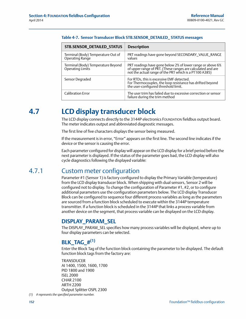
152
Reference Manual00809-0100-4021, Rev GC
Section 4: FOUNDATION fieldbus ConfigurationApril 2014
Foundation™ fieldbus configuration
4.7 LCD display transducer blockThe LCD display connects directly to the 3144P electronics FOUNDATION fieldbus output board. The meter indicates output and abbreviated diagnostic messages.
The first line of five characters displays the sensor being measured.
If the measurement is in error, “Error” appears on the first line. The second line indicates if the device or the sensor is causing the error.
Each parameter configured for display will appear on the LCD display for a brief period before the next parameter is displayed. If the status of the parameter goes bad, the LCD display will also cycle diagnostics following the displayed variable:
4.7.1 Custom meter configurationParameter #1 (Sensor 1) is factory configured to display the Primary Variable (temperature) from the LCD display transducer block. When shipping with dual sensors, Sensor 2 will be configured not to display. To change the configuration of Parameter #1, #2, or to configure additional parameters use the configuration parameters below. The LCD display Transducer Block can be configured to sequence four different process variables as long as the parameters are sourced from a function block scheduled to execute within the 3144P temperature transmitter. If a function block is scheduled in the 3144P that links a process variable from another device on the segment, that process variable can be displayed on the LCD display.
DISPLAY_PARAM_SELThe DISPLAY_PARAM_SEL specifies how many process variables will be displayed, where up to four display parameters can be selected.
BLK_TAG_#(1)
Enter the Block Tag of the function block containing the parameter to be displayed. The default function block tags from the factory are:
TRANSDUCERAI 1400, 1500, 1600, 1700PID 1800 and 1900ISEL 2000CHAR 2100ARTH 2200Output Splitter OSPL 2300
Terminal (Body) Temperature Out of Operating Range
PRT readings have gone beyond SECONDARY_VALUE_RANGE values
Terminal (Body) Temperature Beyond Operating Limits
PRT readings have gone below 2% of lower range or above 6% of upper range of PRT. (These ranges are calculated and are not the actual range of the PRT which is a PT100 A385)
Sensor Degraded For RTDs, this is excessive EMF detected.For Thermocouples, the loop resistance has drifted beyond the user-configured threshold limit.
Calibration Error The user trim has failed due to excessive correction or sensor failure during the trim method
(1) # represents the specified parameter number.
Table 4-7. Sensor Transducer Block STB.SENSOR_DETAILED_ STATUS messages
STB.SENSOR_DETAILED_STATUS Description
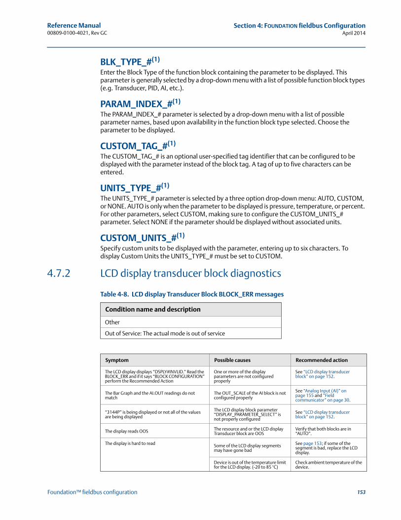
153
Reference Manual 00809-0100-4021, Rev GC
Section 4: FOUNDATION fieldbus ConfigurationApril 2014
Foundation™ fieldbus configuration
BLK_TYPE_#(1)
Enter the Block Type of the function block containing the parameter to be displayed. This parameter is generally selected by a drop-down menu with a list of possible function block types (e.g. Transducer, PID, AI, etc.).
PARAM_INDEX_#(1)
The PARAM_INDEX_# parameter is selected by a drop-down menu with a list of possible parameter names, based upon availability in the function block type selected. Choose the parameter to be displayed.
CUSTOM_TAG_#(1)
The CUSTOM_TAG_# is an optional user-specified tag identifier that can be configured to be displayed with the parameter instead of the block tag. A tag of up to five characters can be entered.
UNITS_TYPE_#(1)
The UNITS_TYPE_# parameter is selected by a three option drop-down menu: AUTO, CUSTOM, or NONE. AUTO is only when the parameter to be displayed is pressure, temperature, or percent. For other parameters, select CUSTOM, making sure to configure the CUSTOM_UNITS_# parameter. Select NONE if the parameter should be displayed without associated units.
CUSTOM_UNITS_#(1)
Specify custom units to be displayed with the parameter, entering up to six characters. To display Custom Units the UNITS_TYPE_# must be set to CUSTOM.
4.7.2 LCD display transducer block diagnostics
Table 4-8. LCD display Transducer Block BLOCK_ERR messages
Condition name and description
Other
Out of Service: The actual mode is out of service
Symptom Possible causes Recommended action
The LCD display displays “DSPLY#INVLID.” Read the BLOCK_ERR and if it says “BLOCK CONFIGURATION” perform the Recommended Action
One or more of the display parameters are not configured properly
See “LCD display transducer block” on page 152.
The Bar Graph and the AI.OUT readings do not match
The OUT_SCALE of the AI block is not configured properly
See “Analog Input (AI)” on page 155 and “Field communicator” on page 30.
“3144P” is being displayed or not all of the values are being displayed
The LCD display block parameter “DISPLAY_PARAMETER_SELECT” is not properly configured
See “LCD display transducer block” on page 152.
The display reads OOS The resource and or the LCD display Transducer block are OOS
Verify that both blocks are in “AUTO”.
The display is hard to read Some of the LCD display segments may have gone bad
See page 153; if some of the segment is bad, replace the LCD display.
Device is out of the temperature limit for the LCD display. (-20 to 85 °C)
Check ambient temperature of the device.
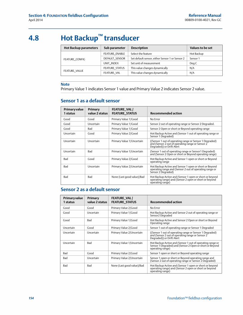
154
Reference Manual00809-0100-4021, Rev GC
Section 4: FOUNDATION fieldbus ConfigurationApril 2014
Foundation™ fieldbus configuration
4.8 Hot Backup™ transducer
NotePrimary Value 1 indicates Sensor 1 value and Primary Value 2 indicates Sensor 2 value.
Sensor 1 as a default sensor
Sensor 2 as a default sensor
Hot Backup parameters Sub parameter Description Values to be set
FEATURE_CONFIG
FEATURE_ENABLE Select the feature Hot Backup
DEFAULT_SENSOR Set default sensor, either Sensor 1 or Sensor 2 Sensor 1
UNIT_INDEX Set unit of measurement Deg C
FEATURE_VALUEFEATURE_STATUS This value changes dynamically N/A
FEATURE_VAL This value changes dynamically N/A
Primary value 1 status
Primary value 2 status
FEATURE_VAL / FEATURE_STATUS Recommended action
Good Good Primary Value 1/Good No Error
Good Uncertain Primary Value 1/Good Sensor 2 out of operating range or Sensor 2 Degraded.
Good Bad Primary Value 1/Good Sensor 2 Open or short or Beyond operating range
Uncertain Good Primary Value 2/Good Hot Backup Active and (Sensor 1 out of operating range or Sensor 1 Degraded)
Uncertain Uncertain Primary Value 1/Uncertain ((Sensor 1 out of operating range or Sensor 1 Degraded) and (Sensor 2 out of operating range or Sensor 2 Degraded)) or Drift Alert
Uncertain Bad Primary Value 1/Uncertain (Sensor 1 out of operating range or Sensor1 Degraded) and (Sensor 2 Open or short or Beyond operating range)
Bad Good Primary Value 2/Good Hot Backup Active and Sensor 1 open or short or Beyond operating range
Bad Uncertain Primary Value 2/Uncertain Hot Backup Active and Sensor 1 open or short or Beyond operating range and (Sensor 2 out of operating range or Sensor 2 Degraded)
Bad Bad None (Last good value)/Bad Hot Backup Active and (Sensor 1 open or short or beyond operating range) and (Sensor 2 open or short or beyond operating range)
Primary value 1 status
Primary value 2 status
FEATURE_VAL / FEATURE_STATUS Recommended action
Good Good Primary Value 2/Good No Error
Good Uncertain Primary Value 1/Good Hot Backup Active and Sensor 2 out of operating range or Sensor2 Degraded
Good Bad Primary Value 1/Good Hot Backup Active and Sensor 2 Open or short or Beyond Operating range
Uncertain Good Primary Value 2/Good Sensor 1 out of operating range or Sensor 1 Degraded
Uncertain Uncertain Primary Value 2/Uncertain ((Sensor 1 out of operating range or Sensor 1 Degraded) and (Sensor 2 out of operating range or Sensor 2 Degraded)) or Drift Alert
Uncertain Bad Primary Value 1/Uncertain Hot Backup Active and (Sensor 1 out of operating range or Sensor 1 Degraded) and (Sensor 2 Open or short or Beyond operating range)
Bad Good Primary Value 2/Good Sensor 1 open or short or Beyond operating range
Bad Uncertain Primary Value 2/Uncertain Sensor 1 open or short or Beyond operating range and (Sensor 2 out of operating range or Sensor 2 Degraded)
Bad Bad None (Last good value)/Bad Hot Backup Active and (Sensor 1 open or short or beyond operating range) and (Sensor 2 open or short or beyond operating range)
155
Reference Manual 00809-0100-4021, Rev GC
Section 4: FOUNDATION fieldbus ConfigurationApril 2014
Foundation™ fieldbus configuration
4.9 Analog Input (AI)
4.9.1 SimulationSimulate replaces the channel value coming from the sensor transducer block. For testing purposes, there are two ways to manually drive the output of the Analog Input Block to a desired value.
Manual modeTo change only the OUT_VALUE and not the OUT_STATUS of the AI Block, place the TARGET MODE of the block to MANUAL, then change the OUT_VALUE to the desired value.
Simulate
1. If the SIMULATE switch is in the OFF position, move it to the ON position. If the SIMULATE switch is already in the ON position, move it to OFF and switch it back to the ON position.
NoteAs a safety measure, the switch must be reset every time power is interrupted to the device to enable SIMULATE. This prevents a device that is tested on the bench from being installed in the process with SIMULATE still active.
2. To change both the OUT_VALUE and OUT_STATUS of the AI Block, set the TARGET MODE to AUTO.
3. Set SIMULATE_ENABLE_DISABLE to ‘Active.’
4. Enter the desired SIMULATE_VALUE to change the OUT_VALUE and SIMULATE_STATUS_QUALITY to change the OUT_STATUS.If errors occur when performing the above steps, make sure that the SIMULATE jumper has been reset after powering the device.
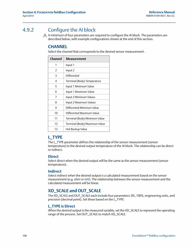
156
Reference Manual00809-0100-4021, Rev GC
Section 4: FOUNDATION fieldbus ConfigurationApril 2014
Foundation™ fieldbus configuration
4.9.2 Configure the AI blockA minimum of four parameters are required to configure the AI block. The parameters are described below, with example configurations shown at the end of this section.
CHANNELSelect the channel that corresponds to the desired sensor measurement .
L_TYPEThe L_TYPE parameter defines the relationship of the sensor measurement (sensor temperature) to the desired output temperature of the AI block. The relationship can be direct or indirect.
DirectSelect direct when the desired output will be the same as the sensor measurement (sensor temperature).
IndirectSelect indirect when the desired output is a calculated measurement based on the sensor measurement (e.g. ohm or mV). The relationship between the sensor measurement and the calculated measurement will be linear.
XD_SCALE and OUT_SCALEThe XD_SCALE and OUT_SCALE each include four parameters: 0%, 100%, engineering units, and precision (decimal point). Set these based on the L_TYPE:
L_TYPE is DirectWhen the desired output is the measured variable, set the XD_SCALE to represent the operating range of the process. Set OUT_SCALE to match XD_SCALE.
Channel Measurement
1 Input 1
2 Input 2
3 Differential
4 Terminal (Body) Temperature
5 Input 1 Minimum Value
6 Input 1 Maximum Value
7 Input 2 Minimum Values
8 Input 2 Maximum Values
9 Differential Minimum Value
10 Differential Maximum Value
11 Terminal (Body) Minimum Value
12 Terminal (Body) Maximum Value
13 Hot Backup Value
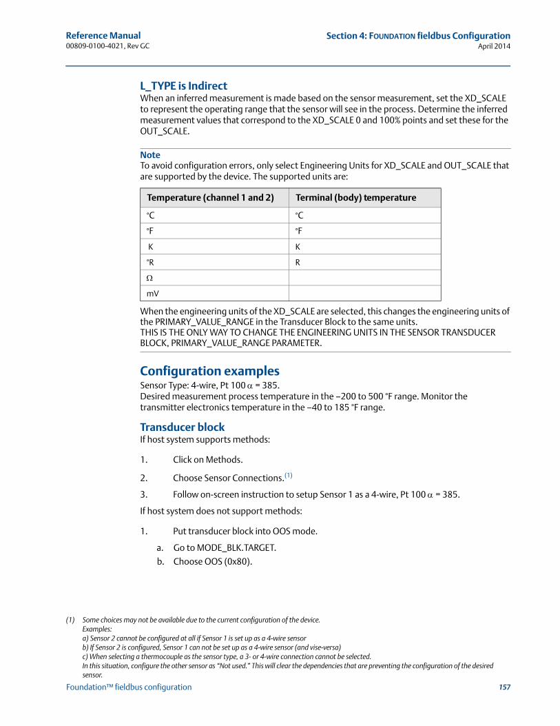
157
Reference Manual 00809-0100-4021, Rev GC
Section 4: FOUNDATION fieldbus ConfigurationApril 2014
Foundation™ fieldbus configuration
L_TYPE is IndirectWhen an inferred measurement is made based on the sensor measurement, set the XD_SCALE to represent the operating range that the sensor will see in the process. Determine the inferred measurement values that correspond to the XD_SCALE 0 and 100% points and set these for the OUT_SCALE.
NoteTo avoid configuration errors, only select Engineering Units for XD_SCALE and OUT_SCALE that are supported by the device. The supported units are:
When the engineering units of the XD_SCALE are selected, this changes the engineering units of the PRIMARY_VALUE_RANGE in the Transducer Block to the same units.THIS IS THE ONLY WAY TO CHANGE THE ENGINEERING UNITS IN THE SENSOR TRANSDUCER BLOCK, PRIMARY_VALUE_RANGE PARAMETER.
Configuration examplesSensor Type: 4-wire, Pt 100 = 385. Desired measurement process temperature in the –200 to 500 °F range. Monitor the transmitter electronics temperature in the –40 to 185 °F range.
Transducer blockIf host system supports methods:
1. Click on Methods.
2. Choose Sensor Connections.(1)
3. Follow on-screen instruction to setup Sensor 1 as a 4-wire, Pt 100 = 385.
If host system does not support methods:
1. Put transducer block into OOS mode.
a. Go to MODE_BLK.TARGET.
b. Choose OOS (0x80).
Temperature (channel 1 and 2) Terminal (body) temperature
°C °C
°F °F
K K
°R R
mV
(1) Some choices may not be available due to the current configuration of the device. Examples: a) Sensor 2 cannot be configured at all if Sensor 1 is set up as a 4-wire sensorb) If Sensor 2 is configured, Sensor 1 can not be set up as a 4-wire sensor (and vise-versa)c) When selecting a thermocouple as the sensor type, a 3- or 4-wire connection cannot be selected.In this situation, configure the other sensor as “Not used.” This will clear the dependencies that are preventing the configuration of the desired sensor.
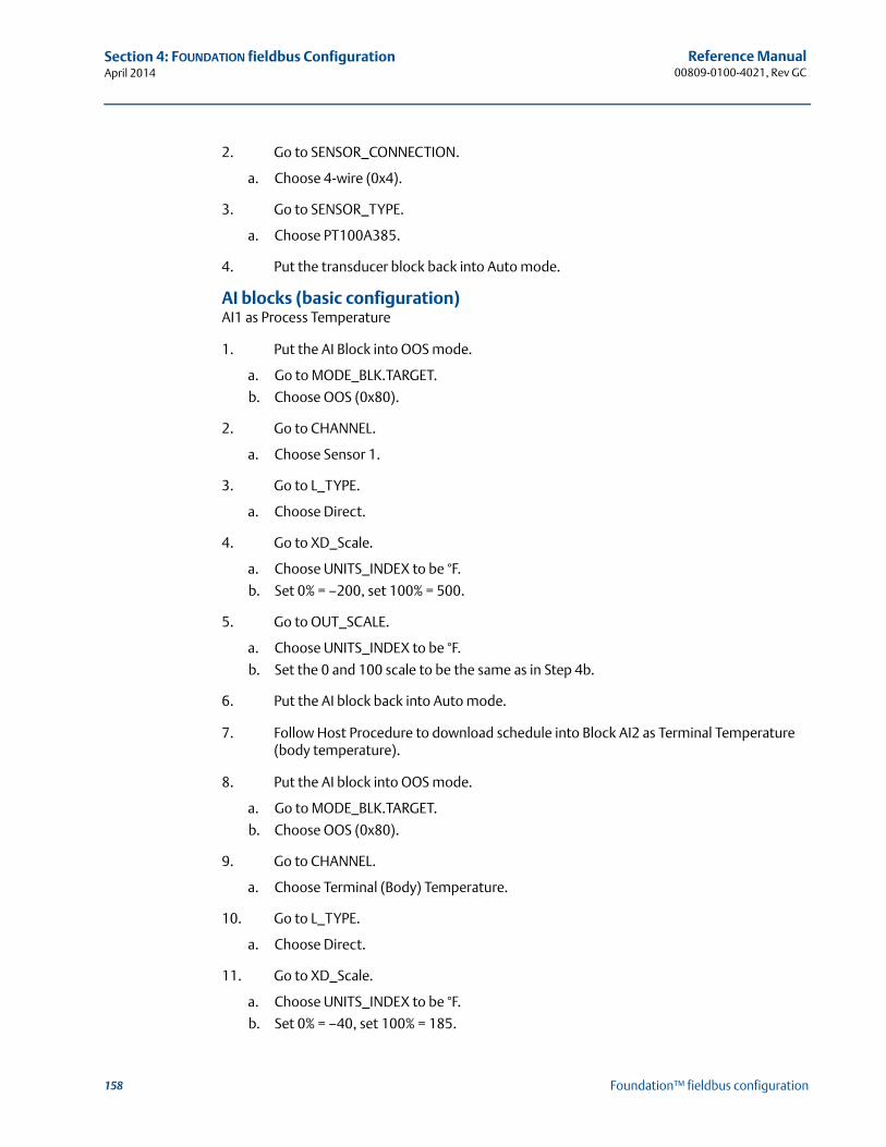
158
Reference Manual00809-0100-4021, Rev GC
Section 4: FOUNDATION fieldbus ConfigurationApril 2014
Foundation™ fieldbus configuration
2. Go to SENSOR_CONNECTION.
a. Choose 4-wire (0x4).
3. Go to SENSOR_TYPE.
a. Choose PT100A385.
4. Put the transducer block back into Auto mode.
AI blocks (basic configuration)AI1 as Process Temperature
1. Put the AI Block into OOS mode.
a. Go to MODE_BLK.TARGET.
b. Choose OOS (0x80).
2. Go to CHANNEL.
a. Choose Sensor 1.
3. Go to L_TYPE.
a. Choose Direct.
4. Go to XD_Scale.
a. Choose UNITS_INDEX to be °F.
b. Set 0% = –200, set 100% = 500.
5. Go to OUT_SCALE.
a. Choose UNITS_INDEX to be °F.
b. Set the 0 and 100 scale to be the same as in Step 4b.
6. Put the AI block back into Auto mode.
7. Follow Host Procedure to download schedule into Block AI2 as Terminal Temperature (body temperature).
8. Put the AI block into OOS mode.
a. Go to MODE_BLK.TARGET.
b. Choose OOS (0x80).
9. Go to CHANNEL.
a. Choose Terminal (Body) Temperature.
10. Go to L_TYPE.
a. Choose Direct.
11. Go to XD_Scale.
a. Choose UNITS_INDEX to be °F.
b. Set 0% = –40, set 100% = 185.
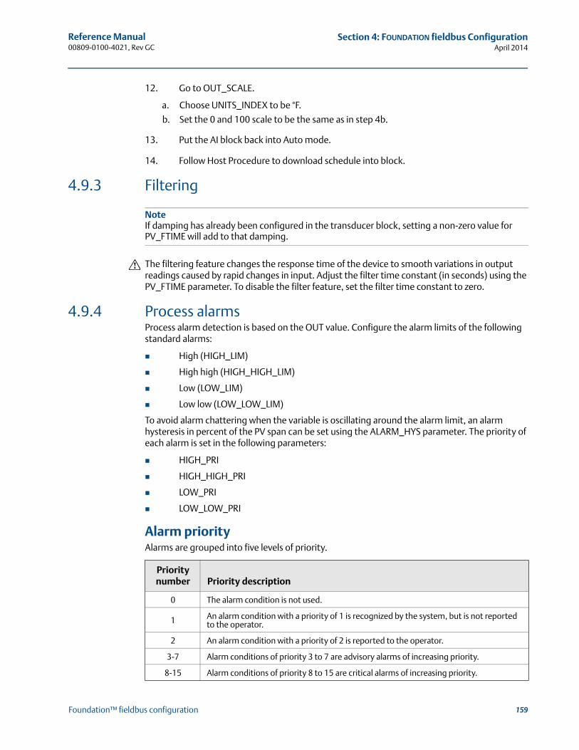
159
Reference Manual 00809-0100-4021, Rev GC
Section 4: FOUNDATION fieldbus ConfigurationApril 2014
Foundation™ fieldbus configuration
12. Go to OUT_SCALE.
a. Choose UNITS_INDEX to be °F.
b. Set the 0 and 100 scale to be the same as in step 4b.
13. Put the AI block back into Auto mode.
14. Follow Host Procedure to download schedule into block.
4.9.3 Filtering
NoteIf damping has already been configured in the transducer block, setting a non-zero value for PV_FTIME will add to that damping.
The filtering feature changes the response time of the device to smooth variations in output readings caused by rapid changes in input. Adjust the filter time constant (in seconds) using the PV_FTIME parameter. To disable the filter feature, set the filter time constant to zero.
4.9.4 Process alarmsProcess alarm detection is based on the OUT value. Configure the alarm limits of the following standard alarms:
High (HIGH_LIM)
High high (HIGH_HIGH_LIM)
Low (LOW_LIM)
Low low (LOW_LOW_LIM)
To avoid alarm chattering when the variable is oscillating around the alarm limit, an alarm hysteresis in percent of the PV span can be set using the ALARM_HYS parameter. The priority of each alarm is set in the following parameters:
HIGH_PRI
HIGH_HIGH_PRI
LOW_PRI
LOW_LOW_PRI
Alarm priorityAlarms are grouped into five levels of priority.
Priority number Priority description
0 The alarm condition is not used.
1 An alarm condition with a priority of 1 is recognized by the system, but is not reported to the operator.
2 An alarm condition with a priority of 2 is reported to the operator.
3-7 Alarm conditions of priority 3 to 7 are advisory alarms of increasing priority.
8-15 Alarm conditions of priority 8 to 15 are critical alarms of increasing priority.
160
Reference Manual00809-0100-4021, Rev GC
Section 4: FOUNDATION fieldbus ConfigurationApril 2014
Foundation™ fieldbus configuration
4.9.5 StatusWhen a PV is passed from one function block to another, it passes a STATUS along with the PV. The STATUS can be: GOOD, BAD, or UNCERTAIN. When a fault occurs in the device, the PV will look at the last value with a STATUS of GOOD and the STATUS will change from GOOD to BAD, or from GOOD to UNCERTAIN. It is important that the control strategy that uses the PV also monitors the STATUS to take appropriate action when the STATUS changes from GOOD to either BAD or UNCERTAIN.
Status optionsStatus Options (STATUS_OPTS) supported by the AI block are shown below:
Propagate fault forwardIf the status from the sensor is Bad, Device failure or Bad, Sensor failure, propagate it to OUT without generating an alarm. The use of these sub-status in OUT is determined by this option. Through this option, the user determines whether alarming (sending of an alert) will be done by the block or propagated downstream for alarming.
Uncertain if limitedSet the output status of the Analog Input block to uncertain if the measured or calculated value is limited.
BAD Set the output status to Bad if the sensor is violating a high or low limit.
Uncertain if man modeSet the output status of the Analog Input block to uncertain if the actual mode of the block is Man.
NoteThe instrument must be in Out of Service mode to set the status option.
4.9.6 Advanced featuresThe following parameters provide the capabilities to drive a discrete output alarm in the event that a process alarm (HI_HI_LIM, HI_LIM, LO_LO_LIM, LO_LIM) has been exceeded.
ALARM_TYPE ALARM_TYPE allows one or more of the process alarm conditions (HI_HI_LIM, HI_LIM, LO_LO_LIM, LO_LIM) detected by the AI function block to be used in setting its OUT_D parameter.
OUT_DOUT_D is the discrete output of the AI function block based on the detection of process alarm condition(s). This parameter may be linked to other function blocks that require a discrete input based on the detected alarm condition.
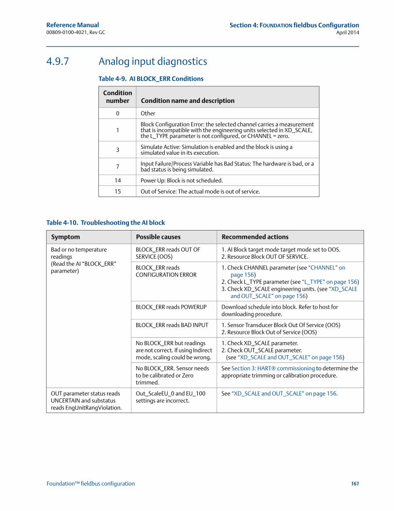
161
Reference Manual 00809-0100-4021, Rev GC
Section 4: FOUNDATION fieldbus ConfigurationApril 2014
Foundation™ fieldbus configuration
4.9.7 Analog input diagnostics
Table 4-9. AI BLOCK_ERR Conditions
Table 4-10. Troubleshooting the AI block
Condition number Condition name and description
0 Other
1Block Configuration Error: the selected channel carries a measurement that is incompatible with the engineering units selected in XD_SCALE, the L_TYPE parameter is not configured, or CHANNEL = zero.
3 Simulate Active: Simulation is enabled and the block is using a simulated value in its execution.
7 Input Failure/Process Variable has Bad Status: The hardware is bad, or a bad status is being simulated.
14 Power Up: Block is not scheduled.
15 Out of Service: The actual mode is out of service.
Symptom Possible causes Recommended actions
Bad or no temperature readings(Read the AI “BLOCK_ERR” parameter)
BLOCK_ERR reads OUT OF SERVICE (OOS)
1. AI Block target mode target mode set to OOS.2. Resource Block OUT OF SERVICE.
BLOCK_ERR reads CONFIGURATION ERROR
1. Check CHANNEL parameter (see “CHANNEL” on page 156)
2. Check L_TYPE parameter (see “L_TYPE” on page 156)3. Check XD_SCALE engineering units. (see “XD_SCALE
and OUT_SCALE” on page 156)
BLOCK_ERR reads POWERUP Download schedule into block. Refer to host for downloading procedure.
BLOCK_ERR reads BAD INPUT 1. Sensor Transducer Block Out Of Service (OOS)2. Resource Block Out of Service (OOS)
No BLOCK_ERR but readings are not correct. If using Indirect mode, scaling could be wrong.
1. Check XD_SCALE parameter.2. Check OUT_SCALE parameter.
(see “XD_SCALE and OUT_SCALE” on page 156)
No BLOCK_ERR. Sensor needs to be calibrated or Zero trimmed.
See Section 3: HART® commissioning to determine the appropriate trimming or calibration procedure.
OUT parameter status reads UNCERTAIN and substatus reads EngUnitRangViolation.
Out_ScaleEU_0 and EU_100 settings are incorrect.
See “XD_SCALE and OUT_SCALE” on page 156.
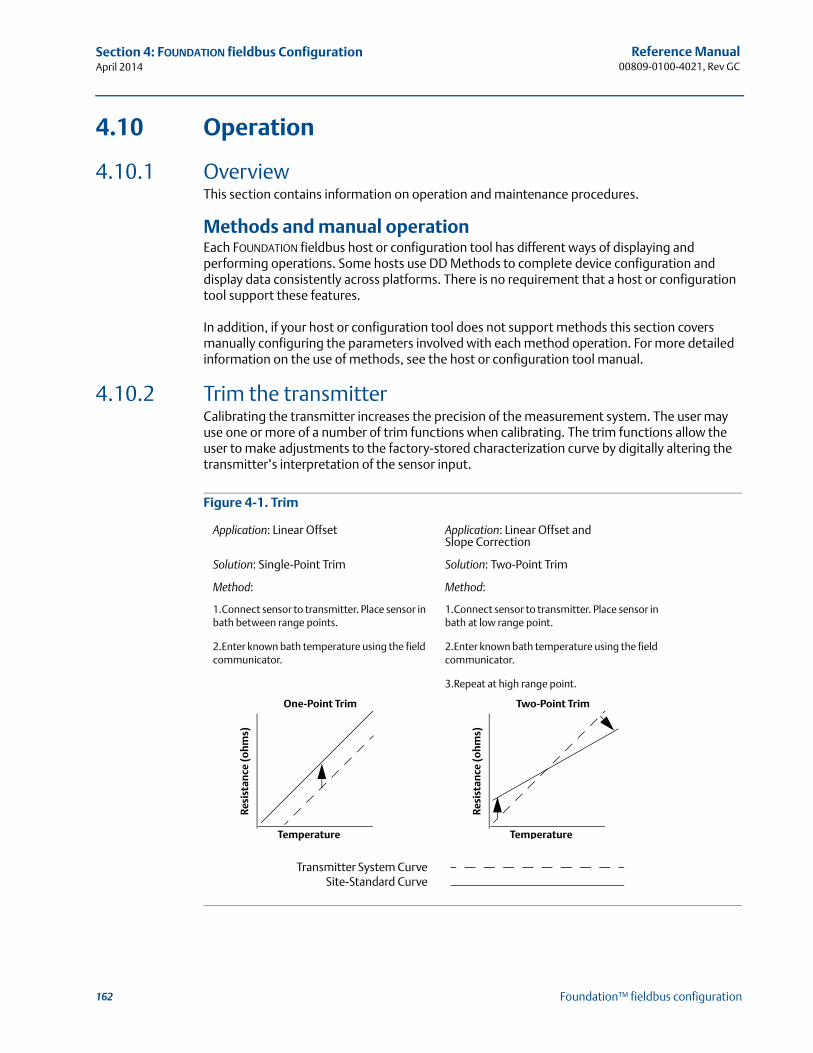
162
Reference Manual00809-0100-4021, Rev GC
Section 4: FOUNDATION fieldbus ConfigurationApril 2014
Foundation™ fieldbus configuration
4.10 Operation
4.10.1 OverviewThis section contains information on operation and maintenance procedures.
Methods and manual operationEach FOUNDATION fieldbus host or configuration tool has different ways of displaying and performing operations. Some hosts use DD Methods to complete device configuration and display data consistently across platforms. There is no requirement that a host or configuration tool support these features.
In addition, if your host or configuration tool does not support methods this section covers manually configuring the parameters involved with each method operation. For more detailed information on the use of methods, see the host or configuration tool manual.
4.10.2 Trim the transmitterCalibrating the transmitter increases the precision of the measurement system. The user may use one or more of a number of trim functions when calibrating. The trim functions allow the user to make adjustments to the factory-stored characterization curve by digitally altering the transmitter’s interpretation of the sensor input.
Figure 4-1. Trim
Application: Linear Offset Application: Linear Offset and Slope Correction
Solution: Single-Point Trim Solution: Two-Point Trim
Method:
1.Connect sensor to transmitter. Place sensor in bath between range points.
2.Enter known bath temperature using the field communicator.
Method:
1.Connect sensor to transmitter. Place sensor in bath at low range point.
2.Enter known bath temperature using the field communicator.
3.Repeat at high range point.
One-Point Trim Two-Point Trim
Transmitter System Curve Site-Standard Curve
Resi
stan
ce (o
hms)
Temperature
Resi
stan
ce (o
hms)
Temperature
163
Reference Manual 00809-0100-4021, Rev GC
Section 4: FOUNDATION fieldbus ConfigurationApril 2014
Foundation™ fieldbus configuration
Sensor calibration, lower and upper trim methodsIn order to calibrate the transmitter, run the Lower and Upper Trim Methods. If your system does not support methods, manually configure the Transducer Block parameters listed below.
1. Set MODE_BLK.TARGET_X to OOS.
2. Set SENSOR_CAL_METHOD_X to User Trim.
3. Set CAL_UNIT_X to supported engineering units in the transducer block.
4. Apply temperature that corresponds to the lower calibration point and allow the temperature to stabilize. The temperature must be between the range limits defined in PRIMRY_VALUE_RANGE_X.
5. Set values of CAL_POINT_LO_X to correspond to the temperature applied by the sensor.
6. Apply temperature, temperature corresponding to the upper calibration.
7. Allow temperature to stabilize.
8. Set CAL_POINT_HI_X.
NoteCAL_POINT_HI_X must be within PRIMARY_VALUE_RANGE_X and greater than CAL_POINT_LO_X + CAL_MIN_SPAN_X.
9. Set SENSOR_CAL_DATE_X to the current date.
10. Set SENSOR_CAL_WHO_X to the person responsible for the calibration.
11. Set SENSOR _CAL_LOC_X to the calibration location.
12. Set MODE_BLK.TARGET_X to AUTO.
NoteIf trim fails the transmitter will automatically revert to factory trim.Excessive correction or sensor failure could cause device status to read “calibration error.” To clear this, trim the transmitter.
Recall factory trim To recall a factory trim on the transmitter, run the Recall Factory Trim. If your system does not support methods, manually configure the transducer block parameters listed below.
1. Set MODE_BLK.TARGET_X to OOS.
2. Set SENSOR_CAL_METHOD_X to Factory Trim.
3. Set SET_FACTORY_TRIM_X to Recall.
4. Set SENSOR_CAL_DATE_X to the current date.
5. Set SENSOR_CAL_WHO_X to the person responsible for the calibration.

164
Reference Manual00809-0100-4021, Rev GC
Section 4: FOUNDATION fieldbus ConfigurationApril 2014
Foundation™ fieldbus configuration
6. Set SENSOR _CAL_LOC_X to the calibration location.
7. Set MODE_BLK.TARGET_X to AUTO.
NoteWhen changing the sensor type, the transmitter reverts to the factory trim and any other trim performed on the transmitter is lost.
4.10.3 Advanced diagnostics
Thermocouple degradation diagnosticThermocouple Degradation Diagnostic acts as a gauge of general thermocouple health and is indicative of any major changes in the status of the thermocouple or the thermocouple loop. The transmitter monitors for increasing resistance of the thermocouple loop to detect drift conditions or wiring condition changes. The degrading thermocouple can be caused by wire thinning, sensor breakdown, moisture intrusion or corrosion and can be an indication of an eventual sensor failure.
How it works: The thermocouple degradation diagnostic measures the amount of resistance on a thermocouple sensor path. Ideally a thermocouple would have zero resistance, but in reality it has some resistance especially for long thermocouple extension wires. As the sensor loop degrades (including sensor degradation and wire or junctions degradation), the resistance of the loop increases. First, the transmitter is configured to a baseline by the user. Then, at least once per second, the degradation diagnostic monitors the resistance in the loop by sending a pulsed current (in microamps) on the loop, measuring the voltage induced and calculating the effective resistance. As the resistance increases, the diagnostic can detect when the resistance exceeds the threshold set by the user at which the diagnostic will provide a digital alert. This feature is not intended to be a precise measurement of thermocouple status, but is a general indicator of thermocouple and thermocouple loop health by providing trending over time.
The thermocouple degradation diagnostic does not detect shorted thermocouple conditions.
Thermocouple diagnostic must be connected, configured, and enabled to read a thermocouple. Once the diagnostic has been activated, a Baseline resistance value is calculated. Then a threshold Trigger must be selected, which can be two, three, or four times the Baseline resistance, or the default of 5000 ohms. If the thermocouple loop resistance reaches the Trigger Level, a maintenance alert is generated.
CautionThe Thermocouple Degradation Diagnostic monitors the health of the entire thermocouple loop, including wiring, terminations, junctions, and the sensor itself. Therefore, it is imperative that the diagnostic baseline resistance be measured with the sensor fully installed and wired in the process, and not on the bench.
NoteThe thermocouple resistance algorithm does not calculate resistance values while the active calibrator mode is enabled.
165
Reference Manual 00809-0100-4021, Rev GC
Section 4: FOUNDATION fieldbus ConfigurationApril 2014
Foundation™ fieldbus configuration
Glossary of AMS Device Manager termsTrigger Level: Threshold resistance value for the thermocouple loop. The Trigger Level may be set for 2, 3, or 4 x Baseline or the default of 5000 Ohms. If the resistance of the thermocouple loop surpasses the Trigger Level, a PlantWeb maintenance alert will be generated.
Resistance: This is the existing resistance reading of the thermocouple loop.
Baseline Value: The resistance of the thermocouple loop obtained after installation, or after resetting the Baseline value. The Trigger Level may be calculated from the Baseline Value.
Trigger Setting: May be set for 2, 3, or 4 x Baseline or the default of 5000 Ohms.
Sensor 1 Degraded: A PlantWeb maintenance alert generated when the Thermocouple Degradation Diagnostic is enabled and the resistance in the loop exceeds the user-configured Trigger Level. This alert indicates maintenance may be necessary or that the thermocouple may have degraded.
Configure: Launches a method so the user can enable or disable the Thermocouple Degradation Diagnostic, select the Trigger Level, and automatically calculates the Baseline value (which may take several seconds).
Reset Baseline Value: Launches a method to recalculate the Baseline value (which may take several seconds).
Enabled: Indicates when the Thermocouple Degradation Diagnostic is enabled for the sensor.
Learning: Indicates when checked that the Baseline Value is being calculated.
Licensed: The check box indicates if Thermocouple Degradation Diagnostic is available for the specific transmitter.
Minimum and maximum temperature trackingMinimum and Maximum Temperature Tracking (Min/Max Tracking) can record lifetime minimum and maximum temperatures with date and time stamps on Rosemount 3144P Temperature Transmitters. This feature records values for Sensor 1, Sensor 2, differential and terminal (body) temperatures. Min/Max Tracking only records temperature maxima and minima obtained since the last reset, and is not a logging function.
To track maximum and minimum temperatures, Min/Max Tracking must be enabled in the transducer function block using a field communicator, AMS Device Manager, or other communicator. While enabled, this feature allows for a reset of information at any time, and all variables can be reset simultaneously. Additionally, Sensor 1, Sensor 2, differential, and terminal (body) temperature minimum and maximum values may be reset individually. Once a particular field has been reset, the previous values are overwritten.
166
Reference Manual00809-0100-4021, Rev GC
Section 4: FOUNDATION fieldbus ConfigurationApril 2014
Foundation™ fieldbus configuration
4.10.4 Statistical process monitoring (SPM) SPM algorithm provides basic information regarding the behavior of process measurements such as PID control block and actual valve position. The algorithm can monitor up to four user selected variables. All variables must reside in a scheduled function block contained in the device. This algorithm can perform higher levels of diagnostics by distribution of computational power to field devices. The two statistical parameters monitored by the SPM are mean and standard deviation. By using the mean and standard deviation, the process or control levels and dynamics can be monitored for change over time. The algorithm also provides:
Configurable limits/alarms for High variation, low dynamics, and mean changes with respect to the learned levels
Necessary statistical information for Regulatory Control Loop Diagnostics, Root Cause Diagnostics, and Operations Diagnostics
NoteFieldbus devices offer a wealth of information to the user. Both process measurement and control is feasible at the device level. The devices contain both the process measurements and control signals that are necessary to not only control the process, but to determine if the process and control is healthy. By looking at the process measurement data and control output over time, additional insight into the process can be gained. Under some load conditions and process demands, changes could be interpreted as degradation of instruments, valves, or major components such as pumps, compressors, heat exchangers, etc. This degradation may indicate that the loop control scheme should be re-tuned or re-evaluated. By learning a healthy process and continually comparing current information to the known healthy information, problems from degradation and eventual failure can be remedied ahead of time. These diagnostics aid in the engineering and maintenance of the devices. False alarms and missed detections may occur. If a reoccurring problem in the process exists, contact Emerson Process Management for assistance.
Configuration phaseThe configuration phase is an inactive state when the SPM algorithm can be configured. In this phase, the block tags, block type, parameter, limits for high variation, low dynamics, and mean change detection can be set by the user. The “Statistical Process Monitoring Activation” parameter must be set to “disabled” to configure any SPM parameter. SPM can monitor any linkable input or output parameter of a scheduled function block that resides in the device.
Learning phaseIn the learning phase of SPM, the algorithm establishes a baseline of the mean and dynamics of a SPM variable. The baseline data is compared to current data for calculating any changes in mean or dynamics of the SPM variables.
Monitoring phaseThe monitoring phase starts once the learning process is complete. The algorithm compares the current values to the baseline values of the mean and standard deviation. During this phase the algorithm computes the percent change in mean and standard deviation to determine if the defined limits are violated.
167
Reference Manual 00809-0100-4021, Rev GC
Section 4: FOUNDATION fieldbus ConfigurationApril 2014
Foundation™ fieldbus configuration
4.10.5 SPM configuration
SPM_Bypass_Verification“Yes” means that the verification of the baseline is turned off while “No” indicates the learned baseline is compared to the next current calculated value to ensure a good baseline value. The recommended value is NO.
SPM_Monitoring_CycleSPM_Monitoring_Cycle is the length of time the process values are taken and used in each calculation. A longer monitoring cycle may provide a more stable mean value with the default set at 15 minutes.
SPM#_Block_Tag Enter the Block Tag of the function block containing the parameter to be monitored. Block tag must be entered, since there is no pull-down menu to select the tag. The tag must be a valid “Block Tag” in the device. The default block tags from the factory are:
AI 1400
AI 1500
PID 1600
ISEL 1700
CHAR 1800
ARITH 1900
SPM can also monitor “out” parameters from other devices. Link the “out” parameter to an input parameter of a function block residing in the device, and set up SPM to monitor the input parameter.
SPM#_Block Type Enter the Block Type of the function block containing the parameter to be monitored.
SPM#_Parameter Index Enter the Parameter Index of the parameter to be monitored.
SPM#_ThresholdsThe SPM#_Thresholds allow alerts to be sent when the values are beyond the threshold values that set for each parameter.
Mean limit Alert Limit value in percent change of the Mean compared with the baseline mean value.
High variationAlert Limit value in percent change of the Stdev compared with the baseline Stdev value.
Low dynamicsAlert Limit value in percent change of the Stdev compared with the baseline Stdev value.
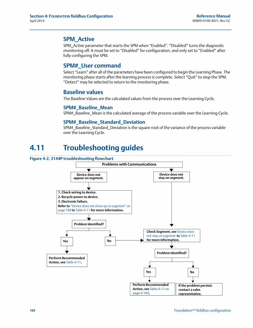
168
Reference Manual00809-0100-4021, Rev GC
Section 4: FOUNDATION fieldbus ConfigurationApril 2014
Foundation™ fieldbus configuration
SPM_ActiveSPM_Active parameter that starts the SPM when “Enabled”. “Disabled” turns the diagnostic monitoring off. It must be set to “Disabled” for configuration, and only set to “Enabled” after fully configuring the SPM.
SPM#_User command Select “Learn” after all of the parameters have been configured to begin the Learning Phase. The monitoring phase starts after the learning process is complete. Select “Quit” to stop the SPM. “Detect” may be selected to return to the monitoring phase.
Baseline values The Baseline Values are the calculated values from the process over the Learning Cycle.
SPM#_Baseline_Mean SPM#_Baseline_Mean is the calculated average of the process variable over the Learning Cycle.
SPM#_Baseline_Standard_DeviationSPM#_Baseline_Standard_Deviation is the square root of the variance of the process variable over the Learning Cycle.
4.11 Troubleshooting guidesFigure 4-2. 3144P troubleshooting flowchart
Device does not appear on segment.
Problem Identified?
Yes No
Perform Recommended Action, see Table 4-11.
Check Segment, see Device does not stay on segment in Table 4-11 for more information.
Problem Identified?
Yes No
Perform Recommended Action, see Table 4-11 on page 4-169.
If the problem persists contact a sales representative.
Problems with Communications
Device does not stay on segment.
1. Check wiring to device. 2. Recycle power to device.3. Electronic failure.Refer to “Device does not show up on segment” on page 169 in Table 4-11 for more information.
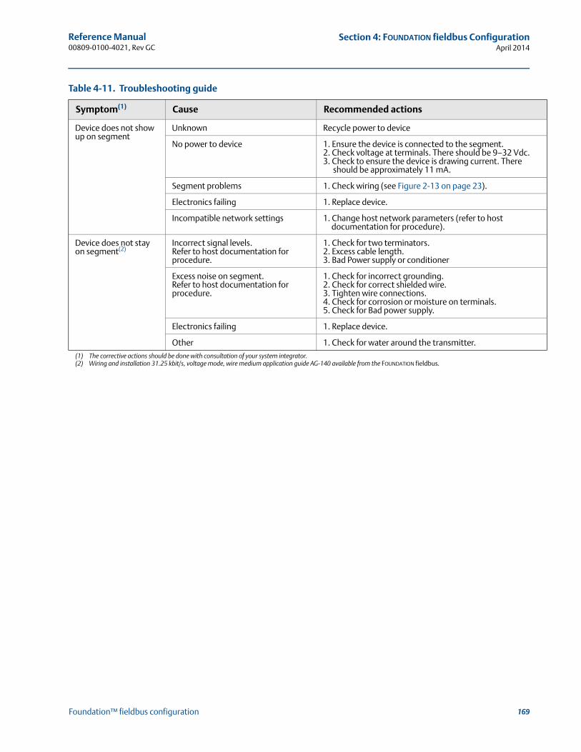
169
Reference Manual 00809-0100-4021, Rev GC
Section 4: FOUNDATION fieldbus ConfigurationApril 2014
Foundation™ fieldbus configuration
Table 4-11. Troubleshooting guide
Symptom(1)
(1) The corrective actions should be done with consultation of your system integrator.
Cause Recommended actions
Device does not show up on segment
Unknown Recycle power to device
No power to device 1. Ensure the device is connected to the segment.2. Check voltage at terminals. There should be 9–32 Vdc.3. Check to ensure the device is drawing current. There
should be approximately 11 mA.
Segment problems 1. Check wiring (see Figure 2-13 on page 23).
Electronics failing 1. Replace device.
Incompatible network settings 1. Change host network parameters (refer to host documentation for procedure).
Device does not stay on segment(2)
(2) Wiring and installation 31.25 kbit/s, voltage mode, wire medium application guide AG-140 available from the FOUNDATION fieldbus.
Incorrect signal levels. Refer to host documentation for procedure.
1. Check for two terminators.2. Excess cable length.3. Bad Power supply or conditioner
Excess noise on segment.Refer to host documentation for procedure.
1. Check for incorrect grounding.2. Check for correct shielded wire.3. Tighten wire connections.4. Check for corrosion or moisture on terminals.5. Check for Bad power supply.
Electronics failing 1. Replace device.
Other 1. Check for water around the transmitter.
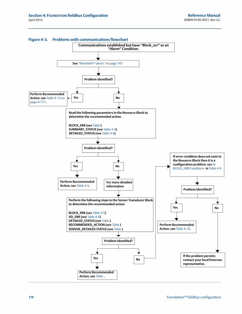
170
Reference Manual00809-0100-4021, Rev GC
Section 4: FOUNDATION fieldbus ConfigurationApril 2014
Foundation™ fieldbus configuration
Figure 4-3. Problems with communications flowchartCommunications established but have “Block_err” or an
“Alarm” Condition.
See “PlantWeb™ alerts” on page 145
Read the following parameters in the Resource Block to determine the recommended action.
BLOCK_ERR (see Table )SUMMARY_STATUS (see Table 4-4)DETAILED_STATUS (see Table 4-4)
Problem Identified?
Yes No
Perform Recommended Action, see Table 4-4.
For more detailed information
Perform the following steps in the Sensor Transducer Block to determine the recommended action.
BLOCK_ERR (see Table 4-5)XD_ERR (see Table 4-6)DETAILED_STATUS (see Table )RECOMMENDED_ACTION (see Table )SENSOR_DETAILED STATUS (see Table )
If error condition does not exist in the Resource Block then it is a configuration problem, see AI BLOCK_ERR Conditions in Table 4-9
Problem Identified?
Yes No
If the problem persists contact your local Emerson representative.
Problem Identified?
Perform Recommended Action, see Table .
Yes No
Perform Recommended Action, see Table 4-10.
Yes NoPerform Recommended Action, see Table 4-12 on page 4-171.
Problem Identified?
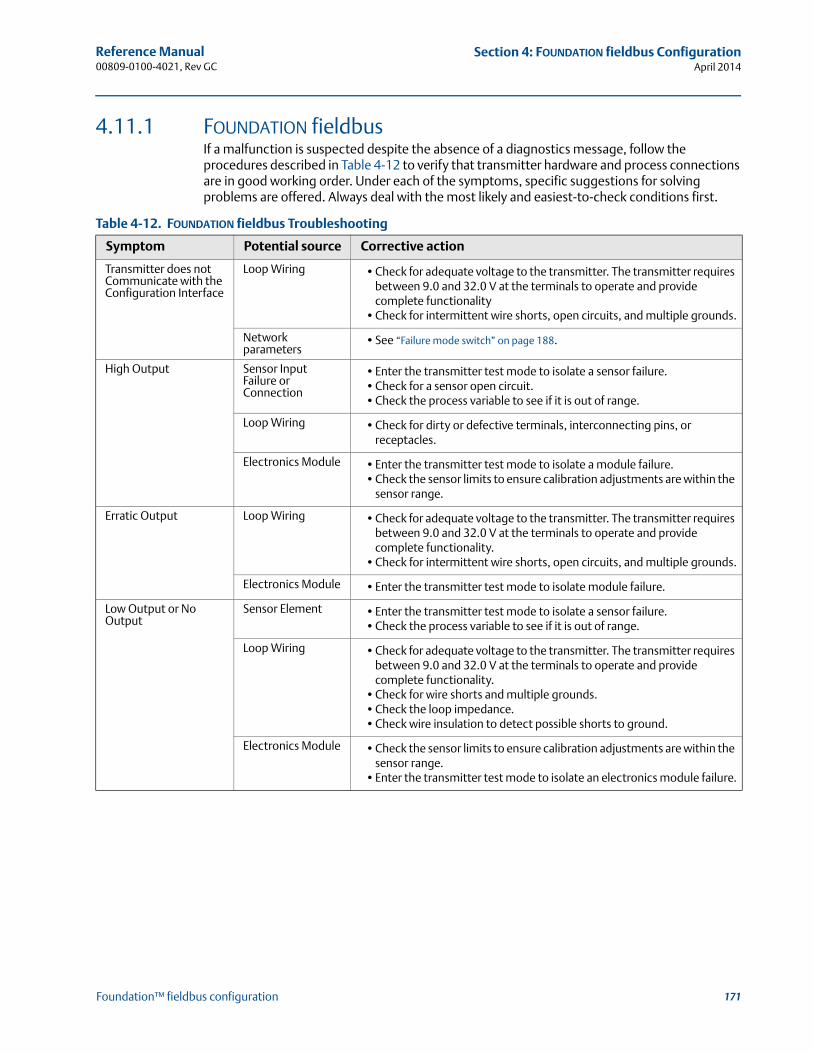
171
Reference Manual 00809-0100-4021, Rev GC
Section 4: FOUNDATION fieldbus ConfigurationApril 2014
Foundation™ fieldbus configuration
4.11.1 FOUNDATION fieldbusIf a malfunction is suspected despite the absence of a diagnostics message, follow the procedures described in Table 4-12 to verify that transmitter hardware and process connections are in good working order. Under each of the symptoms, specific suggestions for solving problems are offered. Always deal with the most likely and easiest-to-check conditions first.
Table 4-12. FOUNDATION fieldbus Troubleshooting
Symptom Potential source Corrective action
Transmitter does not Communicate with the Configuration Interface
Loop Wiring •Check for adequate voltage to the transmitter. The transmitter requires between 9.0 and 32.0 V at the terminals to operate and provide complete functionality
•Check for intermittent wire shorts, open circuits, and multiple grounds.
Network parameters
•See “Failure mode switch” on page 188.
High Output Sensor Input Failure or Connection
•Enter the transmitter test mode to isolate a sensor failure. •Check for a sensor open circuit. •Check the process variable to see if it is out of range.
Loop Wiring •Check for dirty or defective terminals, interconnecting pins, or receptacles.
Electronics Module •Enter the transmitter test mode to isolate a module failure.•Check the sensor limits to ensure calibration adjustments are within the
sensor range.
Erratic Output Loop Wiring •Check for adequate voltage to the transmitter. The transmitter requires between 9.0 and 32.0 V at the terminals to operate and provide complete functionality.
•Check for intermittent wire shorts, open circuits, and multiple grounds.
Electronics Module •Enter the transmitter test mode to isolate module failure.
Low Output or No Output
Sensor Element •Enter the transmitter test mode to isolate a sensor failure.•Check the process variable to see if it is out of range.
Loop Wiring •Check for adequate voltage to the transmitter. The transmitter requires between 9.0 and 32.0 V at the terminals to operate and provide complete functionality.
•Check for wire shorts and multiple grounds. •Check the loop impedance.•Check wire insulation to detect possible shorts to ground.
Electronics Module •Check the sensor limits to ensure calibration adjustments are within the sensor range.
•Enter the transmitter test mode to isolate an electronics module failure.

172
Reference Manual00809-0100-4021, Rev GC
Section 4: FOUNDATION fieldbus ConfigurationApril 2014
Foundation™ fieldbus configuration
4.11.2 LCD displayNoteFor Rosemount 3144P transmitters with FOUNDATION fieldbus, the following LCD display options are not used: Bar graph, Sensor 1, Sensor 2, Differential, Multidrop, and Burst Mode.”
Table 4-13. LCD Display Error Warning Descriptions
MessageLCD display top line
LCD display bottom line
RB.DETAILED_STATUS
Sensor Transducer Block Error “Error” “DVICE”
Manufacturing Block Integrity Error “Error” “DVICE”
Hardware/Software Incompatible “Error” “DVICE”
Non-volatile Memory Integrity Error “Error” “DVICE”
ROM Integrity Error “Error” “DVICE”
Lost Deferred NV Data “Error” “DVICE”
NV Writes Deferred No Errors Displayed
ADB Transducer Block Error No Errors Displayed
STB.SENSR_DETAILED_STATUS
Invalid Configuration “Error” “SNSOR”
ASIC RCV Error “Error” “SNSOR”
ASIC TX Error “Error” “SNSOR”
ASIC Interrupt Error “Error” “SNSOR”
Reference Error “Error” “SNSOR”
ASIC Configuration Error “Error” “SNSOR”
Sensor 1 Open “Error” “SNSOR”
Sensor 1 Shorted “Error” “SNSOR”
Terminal (Body) Temperature Failure “Error” “SNSOR”
Sensor 1 Out of Operating Range No Errors Displayed
Sensor 1 Beyond Operating Limits “Error” “SNSOR”
Terminal (Body) Temperature Out of Operating Range No Errors Displayed
Terminal (Body) Temperature Beyond Operating Limits “Error” “SNSOR”
Sensor 1 Degraded “Error” “SNSOR”
Calibration Error “Error” “SNSOR”
Sensor 2 Open “Error” “SNSOR”
Sensor 2 Shorted “Error” “SNSOR”
Sensor 2 Out of Operating Range No Errors Displayed
Sensor 2 Beyond Operating Limits “Error” “SNSOR”
Sensor 2 Degraded “Error” “SNSOR”
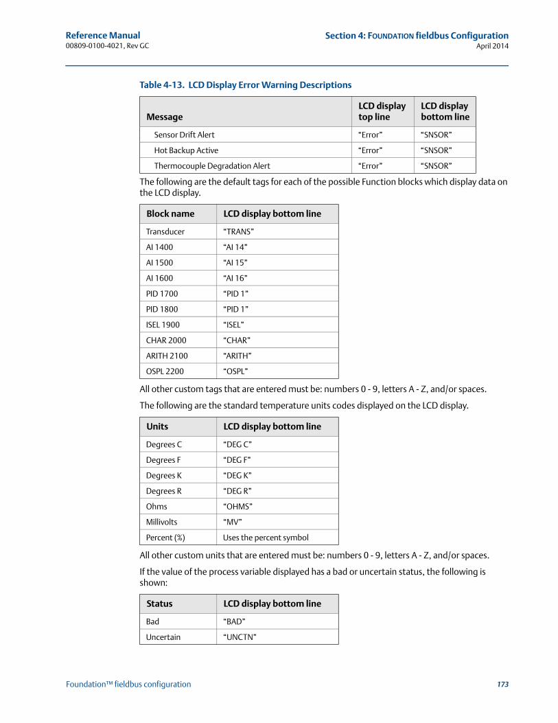
173
Reference Manual 00809-0100-4021, Rev GC
Section 4: FOUNDATION fieldbus ConfigurationApril 2014
Foundation™ fieldbus configuration
The following are the default tags for each of the possible Function blocks which display data on the LCD display.
All other custom tags that are entered must be: numbers 0 - 9, letters A - Z, and/or spaces.
The following are the standard temperature units codes displayed on the LCD display.
All other custom units that are entered must be: numbers 0 - 9, letters A - Z, and/or spaces.
If the value of the process variable displayed has a bad or uncertain status, the following is shown:
Sensor Drift Alert “Error” “SNSOR”
Hot Backup Active “Error” “SNSOR”
Thermocouple Degradation Alert “Error” “SNSOR”
Block name LCD display bottom line
Transducer “TRANS”
AI 1400 “AI 14”
AI 1500 “AI 15”
AI 1600 “AI 16”
PID 1700 “PID 1”
PID 1800 “PID 1”
ISEL 1900 “ISEL”
CHAR 2000 “CHAR”
ARITH 2100 “ARITH”
OSPL 2200 “OSPL”
Units LCD display bottom line
Degrees C “DEG C”
Degrees F “DEG F”
Degrees K “DEG K”
Degrees R “DEG R”
Ohms “OHMS”
Millivolts “MV”
Percent (%) Uses the percent symbol
Status LCD display bottom line
Bad “BAD”
Uncertain “UNCTN”
Table 4-13. LCD Display Error Warning Descriptions
MessageLCD display top line
LCD display bottom line
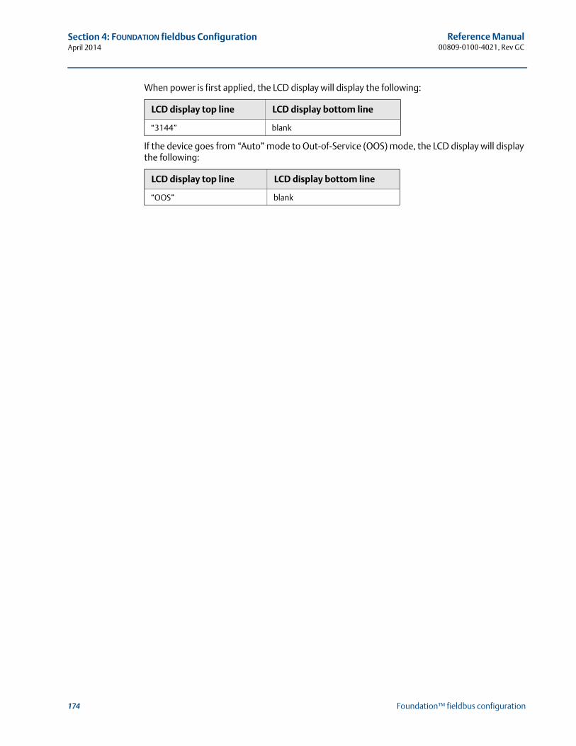
174
Reference Manual00809-0100-4021, Rev GC
Section 4: FOUNDATION fieldbus ConfigurationApril 2014
Foundation™ fieldbus configuration
When power is first applied, the LCD display will display the following:
If the device goes from “Auto” mode to Out-of-Service (OOS) mode, the LCD display will display the following:
LCD display top line LCD display bottom line
“3144” blank
LCD display top line LCD display bottom line
“OOS” blank

Reference Manual 00809-0100-4021, Rev GC
Section 5: MaintenanceApril 2014
175Maintenance
Section 5 Maintenance
Safety messages . . . . . . . . . . . . . . . . . . . . . . . . . . . . . . . . . . . . . . . . . . . . . . . . . . . . . . . . . . . . page 175Maintenance . . . . . . . . . . . . . . . . . . . . . . . . . . . . . . . . . . . . . . . . . . . . . . . . . . . . . . . . . . . . . . . page 176
5.1 Safety messagesInstructions and procedures in this section may require special precautions to ensure the safety of the personnel performing the operations. Information that raises potential safety issues is indicated by a warning symbol ( ). Please refer to the following safety messages before performing an operation preceded by this symbol.
Explosions may result in death or serious injury.
Do not remove the instrument cover in explosive atmospheres when the circuit is live. Before connecting a Field Communicator in an explosive atmosphere, make sure the
instruments in the loop are installed in accordance with intrinsically safe or non-incendive field wiring practices.
Both transmitter covers must be fully engaged to meet explosion-proof requirements.
Electrical shock could cause death or serious injury. If the sensor is installed in a high-voltage environment and a fault or installation error occurs, high voltage may be present on transmitter leads and terminals.
Use extreme caution when making contact with the leads and terminals.Failure to follow these installation guidelines could result in death or serious injury:
Make sure only qualified personnel perform the installation.Process leaks could result in death or serious injury:
Install and tighten thermowells or sensors before applying pressure, or process leakage may result.
Do not remove the thermowell while in operation. Removing while in operation may cause process fluid leaks.
176
Reference Manual00809-0100-4021, Rev GC
Section 5: MaintenanceApril 2014
Maintenance
5.2 MaintenanceThe 3144P Transmitter has no moving parts and requires a minimum amount of scheduled maintenance and features a modular design for easy maintenance. If a malfunction is suspected, check for an external cause before performing the diagnostics discussed in this section.
5.2.1 Test terminal (HART / 4–20 mA only)The test terminal, marked as TEST or (“T”) on the terminal block, and the negative (-) terminal accept MINIGRABBER™, or alligator clips, facilitate in-process checks (see Figure 2-9 on page 21). The test and the negative terminals are connected across a diode through the loop signal current. The current measuring equipment shunts the diode when connected across the test (T) and negative (-) terminals; so as long as the voltage across the terminals is kept below the diode threshold voltage, no current passes through the diode. To ensure there is no leakage current through the diode while making a test reading, or while an indicating meter is connected, the resistance of the test connection or meter should not exceed 10 ohms. A resistance value of 30 ohms will cause an error of approximately 1.0 percent of reading.
5.2.2 Sensor checkoutIf the sensor is installed in a high-voltage environment and a fault condition or installation error occurs, the sensor leads and transmitter terminals could carry lethal voltages. Use extreme caution when making contact with the leads and terminals.
To determine whether the sensor is at fault, replace it with another sensor or connect a test sensor locally at the transmitter to test remote sensor wiring. Transmitters with Option Code C7 (Trim to Special Sensor), are matched to a specific sensor. Select a standard, off-the-shelf sensor for use with the transmitter, or consult the factory for a replacement special sensor/transmitter combination.
5.2.3 Electronics housingThe transmitter is designed with a dual-compartment housing. One compartment contains the electronics module, and the other contains all wiring terminals and communication receptacles.
Removing the electronics module
NoteThe electronics are sealed in a moisture-resistant plastic enclosure referred to as the electronics module. This module is a non-repairable unit and the entire unit must be replaced if a malfunction occurs.
The 3144P electronics module is located in the compartment opposite the wiring terminals.
Use the following procedure to remove the electronics module:
1. Disconnect the power to the transmitter.
2. Remove the cover from the electronics side of the transmitter housing (see “Transmitter Exploded View” on page 203). Do not remove the covers in explosive atmospheres with a live circuit. Remove the LCD display, if applicable.
3. Loosen the two screws anchoring the electronics module assembly to the transmitter housing.
177
Reference Manual 00809-0100-4021, Rev GC
Section 5: MaintenanceApril 2014
Maintenance
4. Firmly grasp the screws and assembly and pull straight out of the housing, taking care not to damage the interconnecting pins.
NoteIf you are replacing the electronics module with a new one, make sure that the alarm switches are set in the same positions.
Replacing the electronics moduleUse the following procedure to reassemble the electronics housing for the 3144P Transmitter.
1. Examine the electronics module to ensure that the failure mode and transmitter security switches are in the desired positions.
2. Carefully insert the electronics module lining up the interconnecting pins with the necessary receptacles on the electronics board.
3. Tighten the two mounting screws. Replace the LCD display, if applicable.
4. Replace the cover. Tighten 1/6 of a revolution after the cover begins to compress the O-ring. Both transmitter covers must be fully engaged to meet explosion proof requirements.
5.2.4 Transmitter diagnostics loggingThe Transmitter Diagnostics Logging feature stores advanced diagnostic information between device resets, such as what caused the transmitter to go into alarm, even if that event has disappeared. For example, if the transmitter detects an open sensor from a loose terminal connection, the transmitter will go into alarm. If wire vibration causes that wire to begin making a good connection, the transmitter will come out of alarm. This jumping in and out of alarm is frustrating when trying to determine what is causing the problem. However, the Transmitter Diagnostics Logging feature keeps track of what caused the transmitter to go into alarm and saves valuable debugging time. The log may be viewed using an asset management software, such as AMS™ Device Manager.

178
Reference Manual00809-0100-4021, Rev GC
Section 5: MaintenanceApril 2014
Maintenance

179
Reference Manual 00809-0100-4021, Rev GC
Section 6: Certified Safety Instrumented System (Safety-Certified)April 2014
Certified safety instrumented system (safety-certified)
Section 6 Certified safety instrumented system (safety-certified)
Safety instrumented systems (SIS) certification . . . . . . . . . . . . . . . . . . . . . . . . . . . . . . . . . page 179Rosemount® 3144P safety certified identification . . . . . . . . . . . . . . . . . . . . . . . . . . . . . . page 179Installation . . . . . . . . . . . . . . . . . . . . . . . . . . . . . . . . . . . . . . . . . . . . . . . . . . . . . . . . . . . . . . . . . page 180Commissioning . . . . . . . . . . . . . . . . . . . . . . . . . . . . . . . . . . . . . . . . . . . . . . . . . . . . . . . . . . . . . page 180Configuration . . . . . . . . . . . . . . . . . . . . . . . . . . . . . . . . . . . . . . . . . . . . . . . . . . . . . . . . . . . . . . page 180Safety messages . . . . . . . . . . . . . . . . . . . . . . . . . . . . . . . . . . . . . . . . . . . . . . . . . . . . . . . . . . . . page 180Certification . . . . . . . . . . . . . . . . . . . . . . . . . . . . . . . . . . . . . . . . . . . . . . . . . . . . . . . . . . . . . . . . page 1813144P safety-certified identification . . . . . . . . . . . . . . . . . . . . . . . . . . . . . . . . . . . . . . . . . . . page 181Installation . . . . . . . . . . . . . . . . . . . . . . . . . . . . . . . . . . . . . . . . . . . . . . . . . . . . . . . . . . . . . . . . . page 181Commissioning . . . . . . . . . . . . . . . . . . . . . . . . . . . . . . . . . . . . . . . . . . . . . . . . . . . . . . . . . . . . . page 181Configuration . . . . . . . . . . . . . . . . . . . . . . . . . . . . . . . . . . . . . . . . . . . . . . . . . . . . . . . . . . . . . . page 181Operation and maintenance . . . . . . . . . . . . . . . . . . . . . . . . . . . . . . . . . . . . . . . . . . . . . . . . . . page 182Specifications . . . . . . . . . . . . . . . . . . . . . . . . . . . . . . . . . . . . . . . . . . . . . . . . . . . . . . . . . . . . . . page 184Spare parts . . . . . . . . . . . . . . . . . . . . . . . . . . . . . . . . . . . . . . . . . . . . . . . . . . . . . . . . . . . . . . . . . page 184
NoteThis section applies to 4–20 mA only.
6.1 Safety instrumented systems (SIS) certificationThe 3144P Temperature Transmitter is a two wire, 4-20 mA smart device. For safety instrumented systems usage it is assumed that the 4-20 mA output is used as the primary safety variable. The transmitter can be equipped with or without the display. The 3144P is classified as a Type B device according to IEC61508, having a hardware fault tolerance of 0.
The 3144P HART® Head Mount transmitter is certified to IEC 61508 for single transmitter use in Safety Instrumented Systems up to SIL 2 and redundant transmitter use in Safety Instrumented Systems up to SIL 3.
6.2 Rosemount® 3144P safety certified identificationAll 3144P HART transmitters must be identified as safety certified before installing into SIS systems.
To identify a safety certified Rosemount 3144P, make sure the device satisfies number 1 below as well as at least one of options 2, 3 or 4.
1. Verify the transmitter was ordered with Output Option code “A”. This signifies that it is a 4-20mA/HART device.
a. For example: MODEL 3144PDxA……….
2. See a Yellow Tag affixed to the outside of the transmitter, or the option code QT in the transmitter model string.
180
Reference Manual00809-0100-4021, Rev GC
Section 6: Certified Safety Instrumented System (Safety-Certified)April 2014
Certified safety instrumented system (safety-certified)
3. Check the Namur Software Revision located on the adhesive transmitter tag.“SW Rev _._._”.
If the Device label software revision is 1.1.1 or higher, the device is safety certified.
4. You can also identify a certified 3144P by its Device Revision which can be found using any HART compliant communicator.
For the 3144P, certified device revisions are as follows:
– Device Revision 5.x (HART 5)
– Device Revision 6.x (HART 7)
6.3 InstallationNo special installation is required in addition to the standard installation practices outlined in this document. Always ensure a proper seal by installing the electronics housing cover(s) so that metal contacts metal.
The loop should be designed so the terminal voltage does not drop below 12 Vdc when the transmitter output is 24.5 mA.
Environmental limits are available in the 3144P Product Data Sheet (Document No. 00813-0100-4728). This document can be found at http://www2.emersonpro-cess.com/en-US/documentation/Pages/DocSearch.aspx.
6.4 CommissioningThe 3144P Safety Certified Transmitter can be commissioned by a person with average knowledge of Rosemount temperature transmitters and the configuration device being used. Please refer to “Confirm HART revision capability” on page 8 to confirm your system's HART Revision capability and to confirm the installation of the correct device drivers (separate drivers required for HART 5 and HART 7).
To commission the 3144P Safety Certified Transmitter using a 375/475 Field Communicator, use the Table 3-1 on page 3-38.
For more information on the field communicator visit http://www2.emersonpro-cess.com/en-US/brands/fieldcommunicator/Pages/fieldcommunicators.aspx.
6.5 ConfigurationUse any HART capable configuration tool or the optional local operator interface to communicate with and verify the initial configuration or any configuration changes made to the 3144P prior to operating in Safety Mode. All configuration methods outlined in Section 3 are the same for the safety certified 3144P temperature transmitter with any differences noted.
6.6 Safety messagesProcedures and instructions in this section may require special precautions to ensure the safety of the personnel performing the operations. Information that raises potential safety issues is indicated by a warning symbol ( ). Refer to the following safety messages before performing an operation preceded by this symbol.

181
Reference Manual 00809-0100-4021, Rev GC
Section 6: Certified Safety Instrumented System (Safety-Certified)April 2014
Certified safety instrumented system (safety-certified)
6.7 CertificationThe 3144P is certified to IEC61508 for single transmitter use in Safety Instrumented Systems up to SIL 2 and redundant transmitter use in Safety Instrumented Systems up to SIL 3. The software is suitable for SIL 3 application.
6.8 3144P safety-certified identificationTo identify Safety Instrumented System (SIS) safety-certified 3144P transmitters, verify one of the following:
1. See a yellow tag affixed to outside of transmitter.
2. Verify the option code QT in the model string.
6.9 InstallationNo special installation is required in addition to the standard installation practices outlined in this document. Always ensure a proper seal by installing the electronics housing cover(s) so that metal contacts metal.
Environmental limits are available in the 3144P Product Data Sheet (Document No. 00813-0100-4021). This document can be found at http://www.emersonpro-cess.com/rosemount/safety/safetyCertTemp.htm.
The loop should be designed so the terminal voltage does not drop below 12 Vdc when the transmitter output is 24.5 mA.
6.10 CommissioningThe 3144P Safety Certified Transmitter can be commissioned by a person with average knowledge of Rosemount temperature transmitters and the configuration device being used.
To commission the 3144P Safety Certified Transmitter, use the HART “Fast Key Sequences” on page 38.
For more information on the Field Communicator see Document No. 00809-0100-4276. AMS™ Device Manager help can be found in the AMS Device Manager on-line guides within the AMS Device Manager system.
6.11 Configuration All configuration methods outlined in Section 3 are the same for the safety certified 3144P temperature transmitter with any differences noted.
Explosions can result in death or serious injury.
Electrical shock can result in death or serious injury.
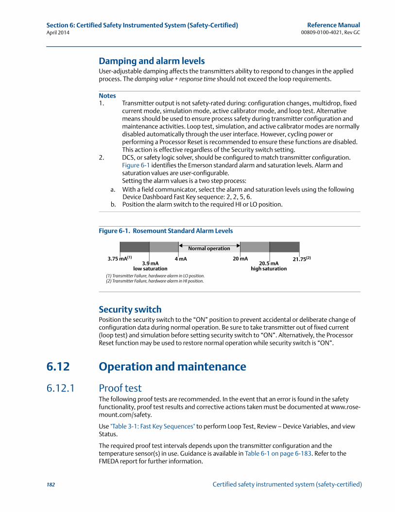
182
Reference Manual00809-0100-4021, Rev GC
Section 6: Certified Safety Instrumented System (Safety-Certified)April 2014
Certified safety instrumented system (safety-certified)
Damping and alarm levelsUser-adjustable damping affects the transmitters ability to respond to changes in the applied process. The damping value + response time should not exceed the loop requirements.
Notes1. Transmitter output is not safety-rated during: configuration changes, multidrop, fixed
current mode, simulation mode, active calibrator mode, and loop test. Alternative means should be used to ensure process safety during transmitter configuration and maintenance activities. Loop test, simulation, and active calibrator modes are normally disabled automatically through the user interface. However, cycling power or performing a Processor Reset is recommended to ensure these functions are disabled. This action is effective regardless of the Security switch setting.
2. DCS, or safety logic solver, should be configured to match transmitter configuration. Figure 6-1 identifies the Emerson standard alarm and saturation levels. Alarm and saturation values are user-configurable.Setting the alarm values is a two step process:
a. With a field communicator, select the alarm and saturation levels using the following Device Dashboard Fast Key sequence: 2, 2, 5, 6.
b. Position the alarm switch to the required HI or LO position.
Figure 6-1. Rosemount Standard Alarm Levels
Security switchPosition the security switch to the “ON” position to prevent accidental or deliberate change of configuration data during normal operation. Be sure to take transmitter out of fixed current (loop test) and simulation before setting security switch to “ON”. Alternatively, the Processor Reset function may be used to restore normal operation while security switch is “ON”.
6.12 Operation and maintenance
6.12.1 Proof test The following proof tests are recommended. In the event that an error is found in the safety functionality, proof test results and corrective actions taken must be documented at www.rose-mount.com/safety.
Use "Table 3-1: Fast Key Sequences" to perform Loop Test, Review – Device Variables, and view Status.
The required proof test intervals depends upon the transmitter configuration and the temperature sensor(s) in use. Guidance is available in Table 6-1 on page 6-183. Refer to the FMEDA report for further information.
(1) Transmitter Failure, hardware alarm in LO position. (2) Transmitter Failure, hardware alarm in HI position.
Normal operation
4 mA 20 mA20.5 mA
high saturation
21.75(2)
3.9 mAlow saturation
3.75 mA(1)
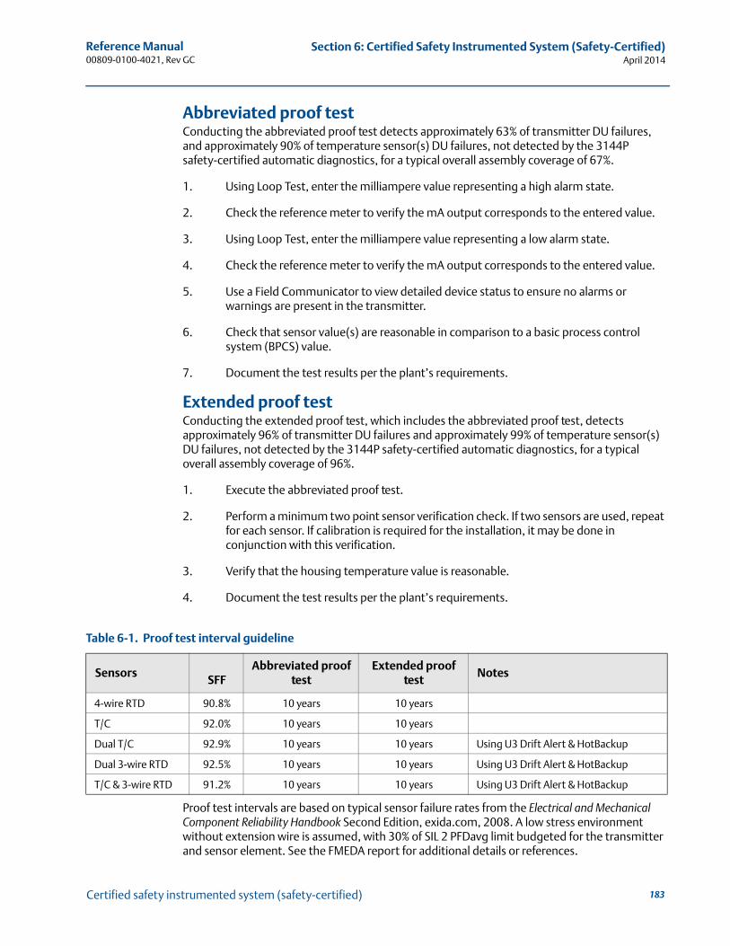
183
Reference Manual 00809-0100-4021, Rev GC
Section 6: Certified Safety Instrumented System (Safety-Certified)April 2014
Certified safety instrumented system (safety-certified)
Abbreviated proof testConducting the abbreviated proof test detects approximately 63% of transmitter DU failures, and approximately 90% of temperature sensor(s) DU failures, not detected by the 3144P safety-certified automatic diagnostics, for a typical overall assembly coverage of 67%.
1. Using Loop Test, enter the milliampere value representing a high alarm state.
2. Check the reference meter to verify the mA output corresponds to the entered value.
3. Using Loop Test, enter the milliampere value representing a low alarm state.
4. Check the reference meter to verify the mA output corresponds to the entered value.
5. Use a Field Communicator to view detailed device status to ensure no alarms or warnings are present in the transmitter.
6. Check that sensor value(s) are reasonable in comparison to a basic process control system (BPCS) value.
7. Document the test results per the plant’s requirements.
Extended proof testConducting the extended proof test, which includes the abbreviated proof test, detects approximately 96% of transmitter DU failures and approximately 99% of temperature sensor(s) DU failures, not detected by the 3144P safety-certified automatic diagnostics, for a typical overall assembly coverage of 96%.
1. Execute the abbreviated proof test.
2. Perform a minimum two point sensor verification check. If two sensors are used, repeat for each sensor. If calibration is required for the installation, it may be done in conjunction with this verification.
3. Verify that the housing temperature value is reasonable.
4. Document the test results per the plant’s requirements.
Proof test intervals are based on typical sensor failure rates from the Electrical and Mechanical Component Reliability Handbook Second Edition, exida.com, 2008. A low stress environment without extension wire is assumed, with 30% of SIL 2 PFDavg limit budgeted for the transmitter and sensor element. See the FMEDA report for additional details or references.
Table 6-1. Proof test interval guideline
SensorsSFF
Abbreviated proof test
Extended proof test
Notes
4-wire RTD 90.8% 10 years 10 years
T/C 92.0% 10 years 10 years
Dual T/C 92.9% 10 years 10 years Using U3 Drift Alert & HotBackup
Dual 3-wire RTD 92.5% 10 years 10 years Using U3 Drift Alert & HotBackup
T/C & 3-wire RTD 91.2% 10 years 10 years Using U3 Drift Alert & HotBackup
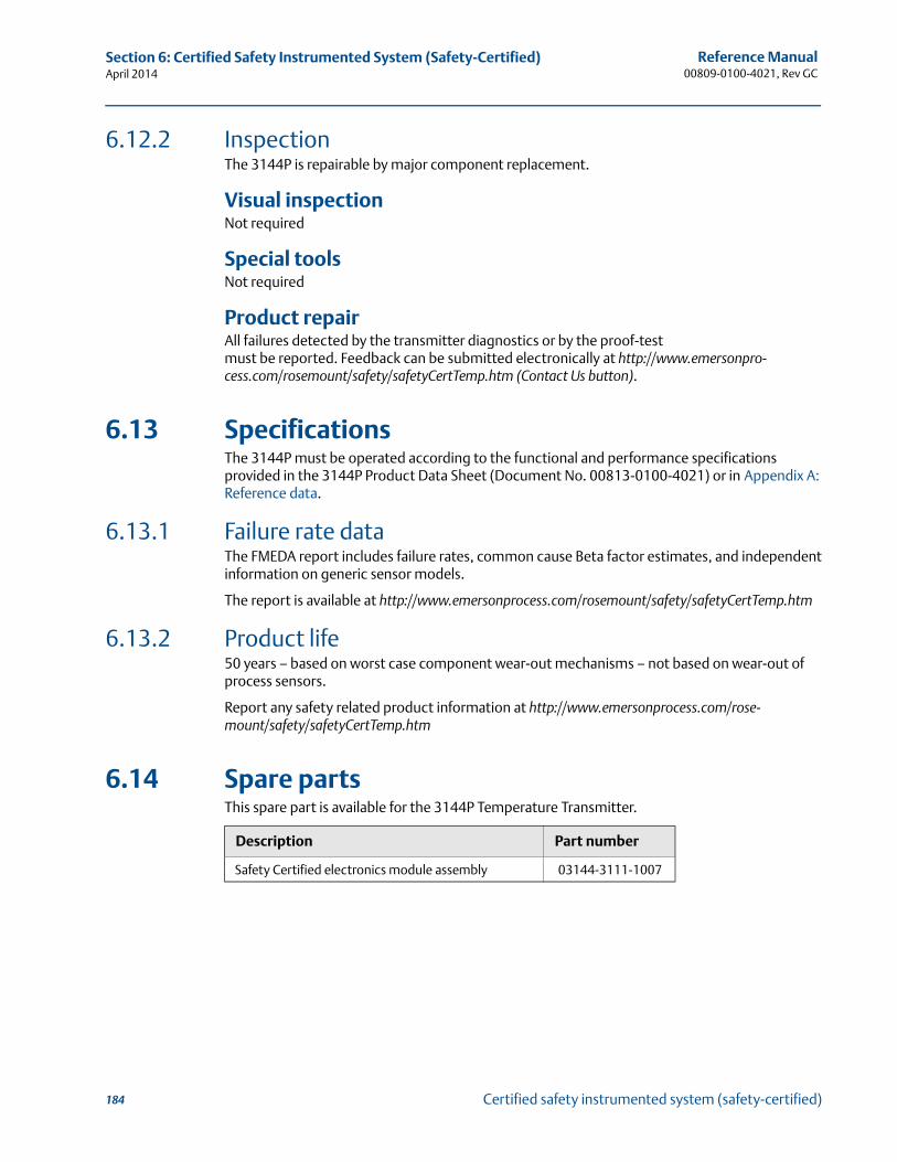
184
Reference Manual00809-0100-4021, Rev GC
Section 6: Certified Safety Instrumented System (Safety-Certified)April 2014
Certified safety instrumented system (safety-certified)
6.12.2 InspectionThe 3144P is repairable by major component replacement.
Visual inspectionNot required
Special toolsNot required
Product repairAll failures detected by the transmitter diagnostics or by the proof-test must be reported. Feedback can be submitted electronically at http://www.emersonpro-cess.com/rosemount/safety/safetyCertTemp.htm (Contact Us button).
6.13 SpecificationsThe 3144P must be operated according to the functional and performance specifications provided in the 3144P Product Data Sheet (Document No. 00813-0100-4021) or in Appendix A: Reference data.
6.13.1 Failure rate dataThe FMEDA report includes failure rates, common cause Beta factor estimates, and independent information on generic sensor models.
The report is available at http://www.emersonprocess.com/rosemount/safety/safetyCertTemp.htm
6.13.2 Product life50 years – based on worst case component wear-out mechanisms – not based on wear-out of process sensors.
Report any safety related product information at http://www.emersonprocess.com/rose-mount/safety/safetyCertTemp.htm
6.14 Spare partsThis spare part is available for the 3144P Temperature Transmitter.
Description Part number
Safety Certified electronics module assembly 03144-3111-1007
Reference Manual 00809-0100-4021, Rev GC
Section 7: Prior Use (PU) Safety Instrumented SystemApril 2014
187Prior use (PU) safety instrumented system
Section 7 Prior use (PU) safety instrumented system
Overview . . . . . . . . . . . . . . . . . . . . . . . . . . . . . . . . . . . . . . . . . . . . . . . . . . . . . . . . . . . . . . . . . . page 187Safe failure fraction . . . . . . . . . . . . . . . . . . . . . . . . . . . . . . . . . . . . . . . . . . . . . . . . . . . . . . . . . . page 188Installation . . . . . . . . . . . . . . . . . . . . . . . . . . . . . . . . . . . . . . . . . . . . . . . . . . . . . . . . . . . . . . . . . page 188
NoteThis section applies to 4–20 mA only.
7.1 OverviewThis section details the requirements for using the 3144P in Prior Use (PU) Safety Instrumented Systems (safety-certified). Although the 3144P is certified for functional safety per IEC61508, the non-certified transmitter may also be used in Safety Applications using the PU. The complete Failure Modes, Effects, and Diagnosis Analysis (FMEDA) was completed to determine the safe failure fraction (SFF) when using this device in a safety-certified application.
FMEDA are the device characteristics that are taken into account when attempting to achieve functional safety certification per IEC61508 of a device. From the FMEDA, failure rates are determined for all temperature sensing device options. Furthermore, the Safe Failure Fraction is calculated for each of the four different input device configurations.
The non-certified 3144P is an isolated 2-wire 4-20 mA SMART device classified as Type B according to IEC61508. It contains self-diagnostics and is programmed to send its output to either a high or low failure state upon internal detection of a failure.
The analysis shows that the device has a safe failure fraction greater than 90% (assuming that the logic solver is programmed to detect over-scale and under-scale currents). The device also has a safe failure fraction of over 90% when used with a temperature sensing device, such as thermocouple or RTD. The device can detect open and short circuit failures of these temperature sensing devices.
Refer to the 3144P safety-certified FMEDA report for failure rate data.
Notes
1. Transmitter output is not Prior Use safety-rated during: configuration changes, multidrop, simulation, active calibrator mode, and loop test. Alternative means should be used to ensure process safety during transmitter configuration and maintenance activities. Loop test, simulation and active calibrator modes are normally disabled automatically through the user interface. However, cycling power or performing a Processor Reset is recommended to ensure these functions are disabled. This action is effective regardless of the Security switch setting.
2. DCS, or safety logic solver, should be configured to match transmitter configuration.
3. Figure 6-1 identifies the Emerson® standard alarm and saturation levels. Alarm and saturation values are user-configurable.
Setting the alarm values is a two step process.
1. With a field communicator, select the alarm and saturation levels.
2. Position the alarm switch to the required HI or LO position.
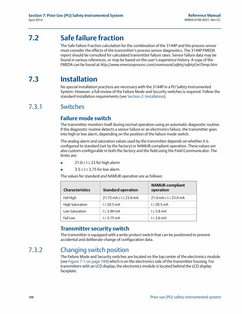
188
Reference Manual00809-0100-4021, Rev GC
Section 7: Prior Use (PU) Safety Instrumented SystemApril 2014
Prior use (PU) safety instrumented system
7.2 Safe failure fractionThe Safe Failure Fraction calculation for the combination of the 3144P and the process sensor must consider the effects of the transmitter’s process sensor diagnostics. The 3144P FMEDA report should be consulted for calculated transmitter failure rates. Sensor failure data may be found in various references, or may be based on the user’s experience history. A copy of the FMEDA can be found at http://www.emersonprocess.com/rosemount/safety/safetyCertTemp.htm
7.3 InstallationNo special installation practices are necessary with the 3144P in a PU Safety Instrumented System. However, a full review of the Failure Mode and Security switches is required. Follow the standard installation requirements (see Section 2: Installation).
7.3.1 Switches
Failure mode switchThe transmitter monitors itself during normal operation using an automatic diagnostic routine. If the diagnostic routine detects a sensor failure or an electronics failure, the transmitter goes into high or low alarm, depending on the position of the failure mode switch.
The analog alarm and saturation values used by the transmitter depends on whether it is configured to standard (set by the factory) or NAMUR-compliant operation. These values are also custom-configurable in both the factory and the field using the Field Communicator. The limits are:
21.0 I 23 for high alarm
3.5 I 3.75 for low alarm
The values for standard and NAMUR operation are as follows:
Transmitter security switchThe transmitter is equipped with a write-protect switch that can be positioned to prevent accidental and deliberate change of configuration data.
7.3.2 Changing switch positionThe Failure Mode and Security switches are located on the top center of the electronics module (see Figure 7-1 on page 189) which is on the electronics side of the transmitter housing. For transmitters with an LCD display, the electronics module is located behind the LCD display faceplate.
Characteristics Standard operationNAMUR-compliant operation
Fail High 21.75 mA I 23.0 mA 21.0 mA I 23.0 mA
High Saturation I 20.5 mA I 20.5 mA
Low Saturation I 3.90 mA I 3.8 mA
Fail Low I 3.75 mA I 3.6 mA
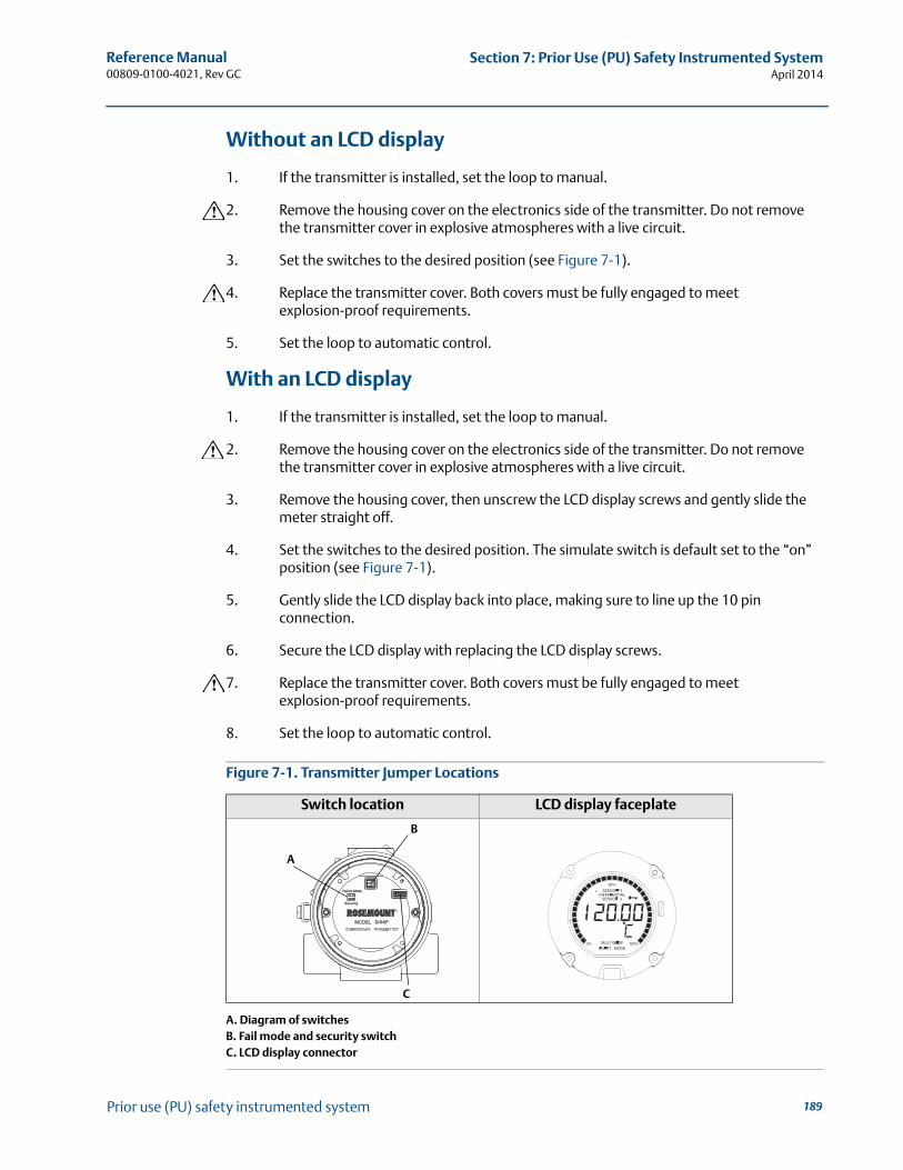
189
Reference Manual 00809-0100-4021, Rev GC
Section 7: Prior Use (PU) Safety Instrumented SystemApril 2014
Prior use (PU) safety instrumented system
Without an LCD display
1. If the transmitter is installed, set the loop to manual.
2. Remove the housing cover on the electronics side of the transmitter. Do not remove the transmitter cover in explosive atmospheres with a live circuit.
3. Set the switches to the desired position (see Figure 7-1).
4. Replace the transmitter cover. Both covers must be fully engaged to meet explosion-proof requirements.
5. Set the loop to automatic control.
With an LCD display
1. If the transmitter is installed, set the loop to manual.
2. Remove the housing cover on the electronics side of the transmitter. Do not remove the transmitter cover in explosive atmospheres with a live circuit.
3. Remove the housing cover, then unscrew the LCD display screws and gently slide the meter straight off.
4. Set the switches to the desired position. The simulate switch is default set to the “on” position (see Figure 7-1).
5. Gently slide the LCD display back into place, making sure to line up the 10 pin connection.
6. Secure the LCD display with replacing the LCD display screws.
7. Replace the transmitter cover. Both covers must be fully engaged to meet explosion-proof requirements.
8. Set the loop to automatic control.
Figure 7-1. Transmitter Jumper Locations
A. Diagram of switchesB. Fail mode and security switchC. LCD display connector
Switch location LCD display faceplate
Failure Mode
Security
A
B
C
190
Reference Manual00809-0100-4021, Rev GC
Section 7: Prior Use (PU) Safety Instrumented SystemApril 2014
Prior use (PU) safety instrumented system
7.3.3 Proof test The following proof tests are recommended. In the event that an error is found in the safety functionality, proof test results and corrective actions taken must be documented at www.rose-mont.com/safety.
Use Table 3-1: Fast Key Sequences to perform Loop Test, Review – Device Variables, and view Status.
The required proof test intervals will depend on the transmitter configuration and the temperature sensor(s) in use. Guidance is available in Table 6-1: Proof test interval guideline Refer to the FMEDA report for further information.
Abbreviated proof testConducting the abbreviated proof test detects approximately 63% of transmitter DU failures and approximately 90% of temperature sensor(s) DU failures, not detected by the 3144P safety-certified automatic diagnostics, for a typical overall assembly coverage of 67%.
1. Using Loop Test, enter the milliampere value representing a high alarm state.
2. Check the reference meter to verify the mA output corresponds to the entered value.
3. Using Loop Test, enter the milliampere value representing a low alarm state.
4. Check the reference meter to verify the mA output corresponds to the entered value.
5. Use a field communicator to view detailed device status to ensure no alarms or warnings are present in the transmitter.
6. Check that sensor value(s) are reasonable in comparison to a basic process control system (BPCS) value.
7. Document the test results per the plant’s requirements.
Extended proof testConducting the extended proof test, which includes the abbreviated proof test, detects approximately 96% of transmitter DU failures and approximately 99% of temperature sensor(s) DU failures, not detected by the 3144P safety-certified automatic diagnostic, for a typical overall assembly coverage of 96%.
1. Execute the abbreviated proof test.
2. Perform a minimum two point sensor verification check. If two sensors are used, repeat for each sensor. If calibration is required for the installation, it may be done in conjunction with this verification.
3. Verify the housing temperature value is reasonable.
4. Document the test results per the plant’s requirements.
Reference Manual 00809-0100-4021, Rev GC
Appendix A: Reference DataApril 2014
191Reference data
Appendix A Reference data
HART® and Foundation™ fieldbus specifications . . . . . . . . . . . . . . . . . . . . . . . . . . . . . . . . page 191HART / 4–20 mA specifications . . . . . . . . . . . . . . . . . . . . . . . . . . . . . . . . . . . . . . . . . . . . . . . page 198Foundation fieldbus specifications . . . . . . . . . . . . . . . . . . . . . . . . . . . . . . . . . . . . . . . . . . . . page 200Dimensional drawings . . . . . . . . . . . . . . . . . . . . . . . . . . . . . . . . . . . . . . . . . . . . . . . . . . . . . . . page 203Ordering information . . . . . . . . . . . . . . . . . . . . . . . . . . . . . . . . . . . . . . . . . . . . . . . . . . . . . . . . page 206Spare parts list . . . . . . . . . . . . . . . . . . . . . . . . . . . . . . . . . . . . . . . . . . . . . . . . . . . . . . . . . . . . . . page 211
A.1 HART® and FOUNDATION™ fieldbus specifications
A.1.1 Functional specifications
InputsUser-selectable. See Accuracy on page 194 for sensor options.
Output2-wire device with either 4–20 mA/HART, linear with temperature or input. Completely digital output with FOUNDATION fieldbus communication (ITK 4.5 compliant).
IsolationInput/output isolation tested up to 500 V rms (707 Vdc).
Humidity limits0–99% Relative Humidity (Non-condensing).
Update timeApproximately 0.5 seconds for a single sensor (1 second for dual sensors).
A.1.2 Physical specifications
Conduit connectionsThe standard field mount housing has ½–14 NPT conduit entries. Additional conduit entry types are available, including PG13.5 (PG11), M20 X 1.5 (CM20), or JIS G ½. When any of these additional entry types are ordered, adapters are placed in the standard field housing so these alternative conduit types fit correctly. See Dimensional drawings on page 203 for dimensions.
Materials of constructionElectronics Housing
Low-copper aluminum or CF-8M (cast version of 316 Stainless Steel)
Paint
Polyurethane

192
Reference Manual00809-0100-4021, Rev GC
Appendix A: Reference DataApril 2014
Reference data
Cover o-ringsBuna-N
MountingTransmitters may be attached directly to the sensor. Optional mounting brackets (codes B4 and B5) permit remote mounting. See Optional Transmitter Mounting Brackets on page 204.
Weight
Enclosure ratingsNEMA 4X, CSA Enclosure Type 4X, IP66, and IP68.
A.1.3 Performance specifications
Stability ±0.1% of reading or 0.1 °C, whichever is greater, for 24 months for RTDs.
±0.1% of reading or 0.1 °C, whichever is greater, for 12 months for thermocouples.
5 year stability ±0.25% of reading or 0.25 °C, whichever is greater, for 5 years for RTDs.
±0.5% of reading or 0.5 °C, whichever is greater, for 5 years for thermocouples.
Vibration effectTested to the following with no effect on performance:
Self calibrationThe analog-to-digital measurement circuitry automatically self-calibrates for each temperature update by comparing the dynamic measurement to extremely stable and accurate internal reference elements.
RFI effectWorst case RFI effect is equivalent to the transmitter’s nominal accuracy specification, according to Accuracy on page 194, when tested in accordance with ENV 50140, “30 V/m (HART) / 20 V/m (HART T/C)” / 10 V/m (FOUNDATION fieldbus), 80 to 1000 MHz, with unshielded cable.
CE electromagnetic compatibility compliance testingThe 3144P meets all requirements listed under IEC 61326: Amendment 1, 2006.
Aluminum(1)
(1) Add 0.5 lb. (0.2 kg) for meter or 1.0 lb. (0.5 kg) for bracket options.
Stainless Steel(1)
3.1 lb. (1.4 kg) 7.8 lb. (3.5 kg)
Frequency Acceleration
10–60 Hz 0.21 mm peak displacement
60–2000 Hz 3 g
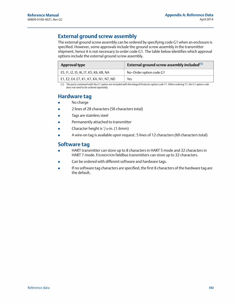
193
Reference Manual 00809-0100-4021, Rev GC
Appendix A: Reference DataApril 2014
Reference data
External ground screw assemblyThe external ground screw assembly can be ordered by specifying code G1 when an enclosure is specified. However, some approvals include the ground screw assembly in the transmitter shipment, hence it is not necessary to order code G1. The table below identifies which approval options include the external ground screw assembly.
Hardware tag No charge
2 lines of 28 characters (56 characters total)
Tags are stainless steel
Permanently attached to transmitter
Character height is 1/16-in. (1.6mm)
A wire-on tag is available upon request. 5 lines of 12 characters (60 characters total)
Software tag HART transmitter can store up to 8 characters in HART 5 mode and 32 characters in
HART 7 mode. FOUNDATION fieldbus transmitters can store up to 32 characters.
Can be ordered with different software and hardware tags.
If no software tag characters are specified, the first 8 characters of the hardware tag are the default.
Approval type External ground screw assembly included(1)
(1) The parts contained with the G1 option are included with the Integral Protector option code T1. When ordering T1, the G1 option code does not need to be ordered separately.
E5, I1, I2, I5, I6, I7, K5, K6, KB, NA No–Order option code G1
E1, E2, E4, E7, K1, K7, KA, N1, N7, ND Yes
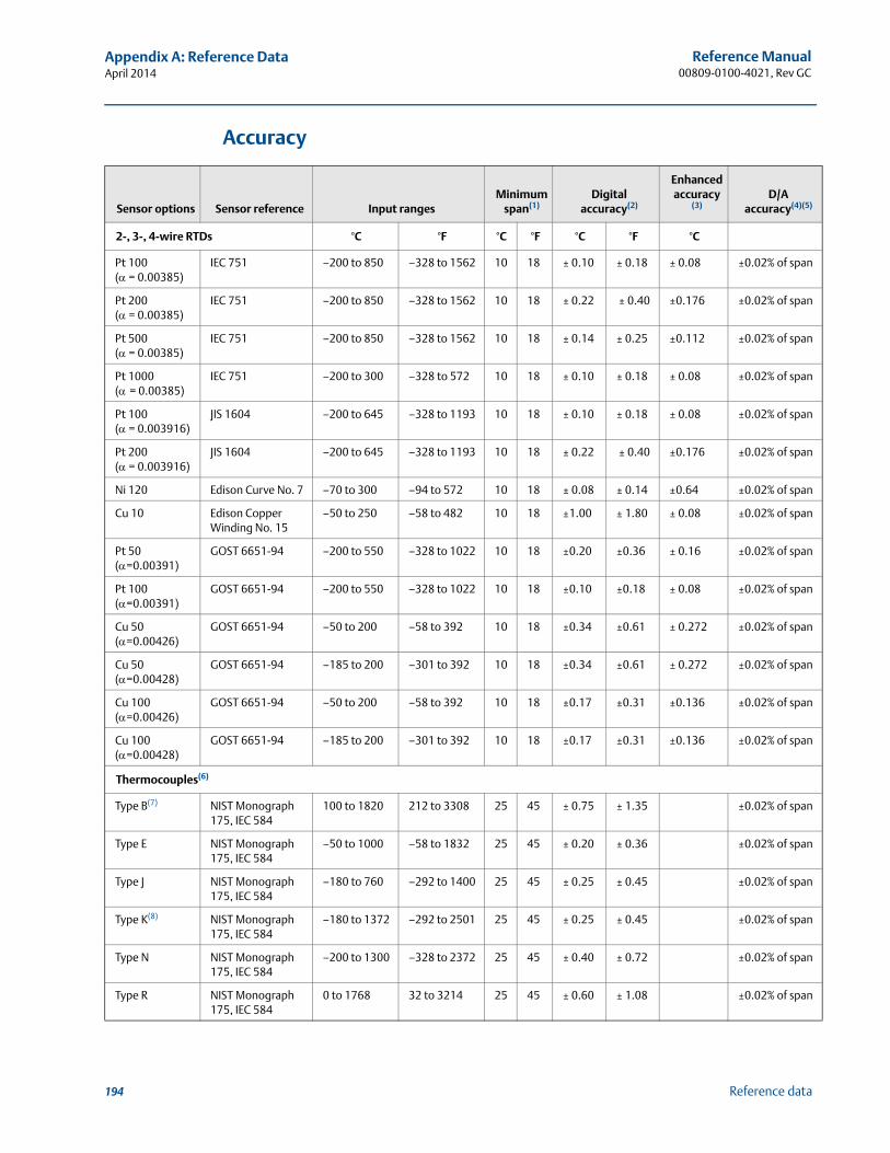
194
Reference Manual00809-0100-4021, Rev GC
Appendix A: Reference DataApril 2014
Reference data
Accuracy
Sensor options Sensor reference Input rangesMinimum
span(1)Digital
accuracy(2)
Enhanced accuracy
(3) D/A
accuracy(4)(5)
2-, 3-, 4-wire RTDs °C °F °C °F °C °F °C
Pt 100 ( = 0.00385)
IEC 751 –200 to 850 –328 to 1562 10 18 ± 0.10 ± 0.18 ± 0.08 ±0.02% of span
Pt 200 ( = 0.00385)
IEC 751 –200 to 850 –328 to 1562 10 18 ± 0.22 ± 0.40 ±0.176 ±0.02% of span
Pt 500 ( = 0.00385)
IEC 751 –200 to 850 –328 to 1562 10 18 ± 0.14 ± 0.25 ±0.112 ±0.02% of span
Pt 1000 ( = 0.00385)
IEC 751 –200 to 300 –328 to 572 10 18 ± 0.10 ± 0.18 ± 0.08 ±0.02% of span
Pt 100 ( = 0.003916)
JIS 1604 –200 to 645 –328 to 1193 10 18 ± 0.10 ± 0.18 ± 0.08 ±0.02% of span
Pt 200 ( = 0.003916)
JIS 1604 –200 to 645 –328 to 1193 10 18 ± 0.22 ± 0.40 ±0.176 ±0.02% of span
Ni 120 Edison Curve No. 7 –70 to 300 –94 to 572 10 18 ± 0.08 ± 0.14 ±0.64 ±0.02% of span
Cu 10 Edison Copper Winding No. 15
–50 to 250 –58 to 482 10 18 ±1.00 ± 1.80 ± 0.08 ±0.02% of span
Pt 50 (=0.00391)
GOST 6651-94 –200 to 550 –328 to 1022 10 18 ±0.20 ±0.36 ± 0.16 ±0.02% of span
Pt 100 (=0.00391)
GOST 6651-94 –200 to 550 –328 to 1022 10 18 ±0.10 ±0.18 ± 0.08 ±0.02% of span
Cu 50 (=0.00426)
GOST 6651-94 –50 to 200 –58 to 392 10 18 ±0.34 ±0.61 ± 0.272 ±0.02% of span
Cu 50 (=0.00428)
GOST 6651-94 –185 to 200 –301 to 392 10 18 ±0.34 ±0.61 ± 0.272 ±0.02% of span
Cu 100 (=0.00426)
GOST 6651-94 –50 to 200 –58 to 392 10 18 ±0.17 ±0.31 ±0.136 ±0.02% of span
Cu 100 (=0.00428)
GOST 6651-94 –185 to 200 –301 to 392 10 18 ±0.17 ±0.31 ±0.136 ±0.02% of span
Thermocouples(6)
Type B(7) NIST Monograph 175, IEC 584
100 to 1820 212 to 3308 25 45 ± 0.75 ± 1.35 ±0.02% of span
Type E NIST Monograph 175, IEC 584
–50 to 1000 –58 to 1832 25 45 ± 0.20 ± 0.36 ±0.02% of span
Type J NIST Monograph 175, IEC 584
–180 to 760 –292 to 1400 25 45 ± 0.25 ± 0.45 ±0.02% of span
Type K(8) NIST Monograph 175, IEC 584
–180 to 1372 –292 to 2501 25 45 ± 0.25 ± 0.45 ±0.02% of span
Type N NIST Monograph 175, IEC 584
–200 to 1300 –328 to 2372 25 45 ± 0.40 ± 0.72 ±0.02% of span
Type R NIST Monograph 175, IEC 584
0 to 1768 32 to 3214 25 45 ± 0.60 ± 1.08 ±0.02% of span
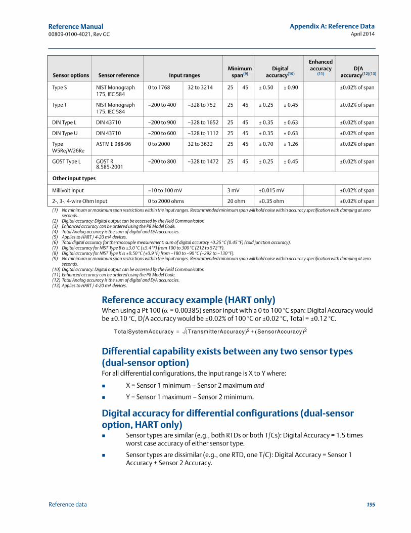
195
Reference Manual 00809-0100-4021, Rev GC
Appendix A: Reference DataApril 2014
Reference data
Reference accuracy example (HART only)When using a Pt 100 (= 0.00385) sensor input with a 0 to 100 °C span: Digital Accuracy would be ±0.10 °C, D/A accuracy would be ±0.02% of 100 °C or ±0.02 °C, Total = ±0.12 °C.
Differential capability exists between any two sensor types (dual-sensor option)For all differential configurations, the input range is X to Y where:
X = Sensor 1 minimum – Sensor 2 maximum and
Y = Sensor 1 maximum – Sensor 2 minimum.
Digital accuracy for differential configurations (dual-sensor option, HART only) Sensor types are similar (e.g., both RTDs or both T/Cs): Digital Accuracy = 1.5 times
worst case accuracy of either sensor type.
Sensor types are dissimilar (e.g., one RTD, one T/C): Digital Accuracy = Sensor 1 Accuracy + Sensor 2 Accuracy.
Sensor options Sensor reference Input rangesMinimum
span(9)Digital
accuracy(10)
Enhanced accuracy
(11) D/A
accuracy(12)(13)
Type S NIST Monograph 175, IEC 584
0 to 1768 32 to 3214 25 45 ± 0.50 ± 0.90 ±0.02% of span
Type T NIST Monograph 175, IEC 584
–200 to 400 –328 to 752 25 45 ± 0.25 ± 0.45 ±0.02% of span
DIN Type L DIN 43710 –200 to 900 –328 to 1652 25 45 ± 0.35 ± 0.63 ±0.02% of span
DIN Type U DIN 43710 –200 to 600 –328 to 1112 25 45 ± 0.35 ± 0.63 ±0.02% of span
Type W5Re/W26Re
ASTM E 988-96 0 to 2000 32 to 3632 25 45 ± 0.70 ± 1.26 ±0.02% of span
GOST Type L GOST R 8.585-2001
–200 to 800 –328 to 1472 25 45 ± 0.25 ± 0.45 ±0.02% of span
Other input types
Millivolt Input –10 to 100 mV 3 mV ±0.015 mV ±0.02% of span
2-, 3-, 4-wire Ohm Input 0 to 2000 ohms 20 ohm ±0.35 ohm ±0.02% of span
(1) No minimum or maximum span restrictions within the input ranges. Recommended minimum span will hold noise within accuracy specification with damping at zero seconds.
(2) Digital accuracy: Digital output can be accessed by the Field Communicator.(3) Enhanced accuracy can be ordered using the P8 Model Code.(4) Total Analog accuracy is the sum of digital and D/A accuracies.(5) Applies to HART / 4-20 mA devices.(6) Total digital accuracy for thermocouple measurement: sum of digital accuracy +0.25 °C (0.45 °F) (cold junction accuracy).(7) Digital accuracy for NIST Type B is ±3.0 °C (±5.4 °F) from 100 to 300 °C (212 to 572 °F).(8) Digital accuracy for NIST Type K is ±0.50 °C (±0.9 °F) from –180 to –90 °C (–292 to –130 °F).(9) No minimum or maximum span restrictions within the input ranges. Recommended minimum span will hold noise within accuracy specification with damping at zero
seconds.(10) Digital accuracy: Digital output can be accessed by the Field Communicator.(11) Enhanced accuracy can be ordered using the P8 Model Code.(12) Total Analog accuracy is the sum of digital and D/A accuracies.(13) Applies to HART / 4-20 mA devices.
TotalSystemAccuracy TransmitterAccuracy 2 SensorAccuracy 2+=
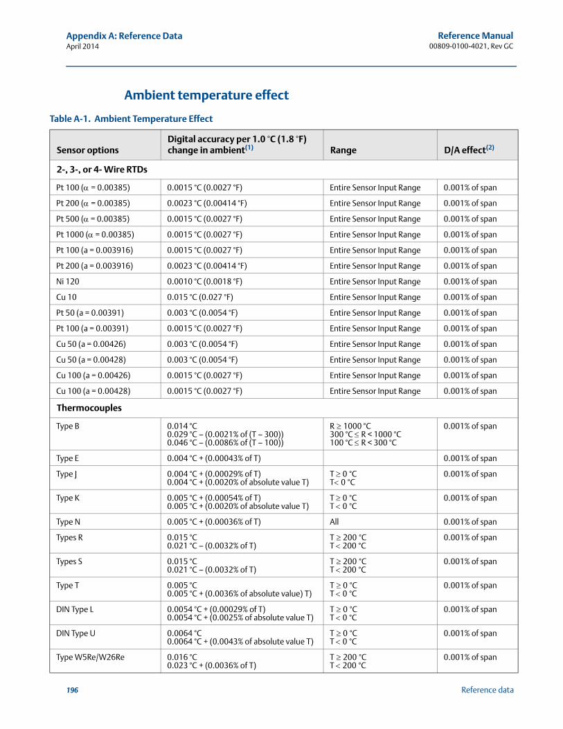
196
Reference Manual00809-0100-4021, Rev GC
Appendix A: Reference DataApril 2014
Reference data
Ambient temperature effect
Table A-1. Ambient Temperature Effect
Sensor optionsDigital accuracy per 1.0 °C (1.8 °F) change in ambient(1) Range D/A effect(2)
2-, 3-, or 4- Wire RTDs
Pt 100 (= 0.00385) 0.0015 °C (0.0027 °F) Entire Sensor Input Range 0.001% of span
Pt 200 (= 0.00385) 0.0023 °C (0.00414 °F) Entire Sensor Input Range 0.001% of span
Pt 500 ( = 0.00385) 0.0015 °C (0.0027 °F) Entire Sensor Input Range 0.001% of span
Pt 1000 ( = 0.00385) 0.0015 °C (0.0027 °F) Entire Sensor Input Range 0.001% of span
Pt 100 (a = 0.003916) 0.0015 °C (0.0027 °F) Entire Sensor Input Range 0.001% of span
Pt 200 (a = 0.003916) 0.0023 °C (0.00414 °F) Entire Sensor Input Range 0.001% of span
Ni 120 0.0010 °C (0.0018 °F) Entire Sensor Input Range 0.001% of span
Cu 10 0.015 °C (0.027 °F) Entire Sensor Input Range 0.001% of span
Pt 50 (a = 0.00391) 0.003 °C (0.0054 °F) Entire Sensor Input Range 0.001% of span
Pt 100 (a = 0.00391) 0.0015 °C (0.0027 °F) Entire Sensor Input Range 0.001% of span
Cu 50 (a = 0.00426) 0.003 °C (0.0054 °F) Entire Sensor Input Range 0.001% of span
Cu 50 (a = 0.00428) 0.003 °C (0.0054 °F) Entire Sensor Input Range 0.001% of span
Cu 100 (a = 0.00426) 0.0015 °C (0.0027 °F) Entire Sensor Input Range 0.001% of span
Cu 100 (a = 0.00428) 0.0015 °C (0.0027 °F) Entire Sensor Input Range 0.001% of span
Thermocouples
Type B 0.014 °C 0.029 °C – (0.0021% of (T – 300))0.046 °C – (0.0086% of (T – 100))
R1000 °C300 °C R < 1000 °C100 °C R < 300 °C
0.001% of span
Type E 0.004 °C + (0.00043% of T) 0.001% of span
Type J 0.004 °C + (0.00029% of T)0.004 °C + (0.0020% of absolute value T)
T 0°CT0°C
0.001% of span
Type K 0.005 °C + (0.00054% of T) 0.005 °C + (0.0020% of absolute value T)
T 0°CT 0°C
0.001% of span
Type N 0.005 °C + (0.00036% of T) All 0.001% of span
Types R 0.015 °C 0.021 °C – (0.0032% of T)
T200°CT 200°C
0.001% of span
Types S 0.015 °C 0.021 °C – (0.0032% of T)
T200°CT 200°C
0.001% of span
Type T 0.005 °C 0.005 °C + (0.0036% of absolute value) T)
T0°CT 0°C
0.001% of span
DIN Type L 0.0054 °C + (0.00029% of T) 0.0054 °C + (0.0025% of absolute value T)
T0°CT 0°C
0.001% of span
DIN Type U 0.0064 °C 0.0064 °C + (0.0043% of absolute value T)
T0°CT 0°C
0.001% of span
Type W5Re/W26Re 0.016 °C 0.023 °C + (0.0036% of T)
T200°CT 200°C
0.001% of span
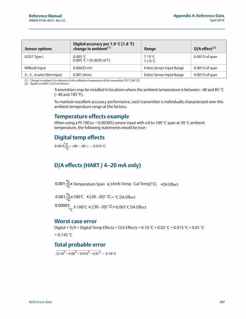
197
Reference Manual 00809-0100-4021, Rev GC
Appendix A: Reference DataApril 2014
Reference data
Transmitters may be installed in locations where the ambient temperature is between –40 and 85 °C (–40 and 185 °F).
To maintain excellent accuracy performance, each transmitter is individually characterized over this ambient temperature range at the factory.
Temperature effects exampleWhen using a Pt 100 ( = 0.00385) sensor input with a 0 to 100 °C span at 30 °C ambient temperature, the following statements would be true:
Digital temp effects
D/A effects (HART / 4–20 mA only)
Worst case errorDigital + D/A + Digital Temp Effects + D/A Effects = 0.10 °C + 0.02 °C + 0.015 °C + 0.01 °C
= 0.145 °C
Total probable error
GOST Type L 0.005 °C 0.005 °C + (0.003% of T)
T ³ 0 °CT < 0 °C
0.001% of span
Millivolt Input 0.00025 mV Entire Sensor Input Range 0.001% of span
2-, 3-, 4-wire Ohm Input 0.007 ohms Entire Sensor Input Range 0.001% of span
(1) Change in ambient is in reference to the calibration temperature of the transmitter (20 °C [68 °F]).(2) Applies to HART / 4-20 mA devices.
Sensor optionsDigital accuracy per 1.0 °C (1.8 °F) change in ambient(1) Range D/A effect(2)
0.0015 CC------- 30 20– 0.015C=°
0.001 %C-------x Temperature Span x (Amb Temp - Cal Temp)° =DA EffectC
0.001 %C-------x100°C x (30 - 20)° C °C DA Effect=
0.00001°C
100°C (30 - 20)°x =0.001°C DA EffectCX
0.102
0.022
0.0152
0.012
+ + + 0.10C=

198
Reference Manual00809-0100-4021, Rev GC
Appendix A: Reference DataApril 2014
Reference data
A.2 HART / 4–20 mA specifications
Power supplyExternal power supply is required. Transmitters operate on 12.0 to 42.4 Vdc transmitter terminal voltage (with 250 ohm load, 18.1 Vdc power supply voltage is required). Transmitter power terminals are rated to 42.4 Vdc.
Wiring diagramSee Figure A-1 on page 205.
AlarmsCustom factory configurations of alarm and saturation levels are available for valid values with option code C1. These values can also be configured in the field using a field communicator.
Transient protection (option code T1)The transient protector helps prevent damage to the transmitter from transients induced on the loop wiring by lightning, welding, heavy electrical equipment, or switch gears. The transient protection electronics are contained in an add-on assembly that attaches to the standard transmitter terminal block. The external ground lug assembly (code G1) is included with the Transient Protector. The transient protector has been tested per the following standard:
IEEE C62.41-1991 (IEEE 587)/ Location Categories B3.6kV/3kA peak (1.2 � 50 S Wave 8 � 20 S Combination Wave)6kV/0.5kA peak (100 kHz Ring Wave)EFT, 4kVpeak, 2.5kHz, 5*50nS
Loop resistance added by protector: 22 ohms max.
Nominal clamping voltages: 90 V (common mode), 77 V (normal mode)
LCD displayOptional five-digit LCD display includes 0–100% bar graph. Digits are 0.4 inches (8 mm) high. Display options include engineering units (°F, °C, °R, K, ohms, and millivolts), percent, and milliamperes. The display can also be set to alternate between engineering units/milliamperes, Sensor 1/Sensor 2, Sensor 1/Sensor 2/Differential Temperature, and Sensor 1/Sensor2/Average Temperature. All display options, including the decimal point, may be reconfigured in the field using a field communicator or AMS Device Manager.
Turn-on timeSpecification performance is achieved less than six seconds after power is applied to the transmitter when the damping value is set to 0 seconds.
Power supply effectLess than ±0.005% of span per volt.
SIS safety transmitter failure valuesIEC 61508 Safety Certified SIL 2 Claim Limit
Safety accuracy: Span 100 °C: ±2%(1) of process variable spanSpan 100 °C: ± 2 °C
Safety response time: 5 seconds
(1) A 2% variation of the transmitter mA output is allowed before a safety trip. Trip values in the DCS or safety logic solver should be derated by 2%.
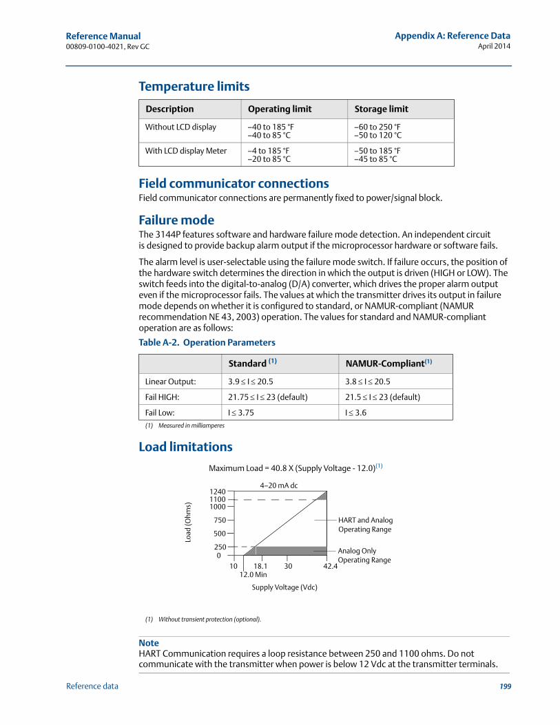
199
Reference Manual 00809-0100-4021, Rev GC
Appendix A: Reference DataApril 2014
Reference data
Temperature limits
Field communicator connectionsField communicator connections are permanently fixed to power/signal block.
Failure modeThe 3144P features software and hardware failure mode detection. An independent circuit is designed to provide backup alarm output if the microprocessor hardware or software fails.
The alarm level is user-selectable using the failure mode switch. If failure occurs, the position of the hardware switch determines the direction in which the output is driven (HIGH or LOW). The switch feeds into the digital-to-analog (D/A) converter, which drives the proper alarm output even if the microprocessor fails. The values at which the transmitter drives its output in failure mode depends on whether it is configured to standard, or NAMUR-compliant (NAMUR recommendation NE 43, 2003) operation. The values for standard and NAMUR-compliant operation are as follows:
Load limitations
NoteHART Communication requires a loop resistance between 250 and 1100 ohms. Do not communicate with the transmitter when power is below 12 Vdc at the transmitter terminals.
Description Operating limit Storage limit
Without LCD display –40 to 185 °F–40 to 85 °C
–60 to 250 °F–50 to 120 °C
With LCD display Meter –4 to 185 °F–20 to 85 °C
–50 to 185 °F–45 to 85 °C
Table A-2. Operation Parameters
Standard (1)
(1) Measured in milliamperes
NAMUR-Compliant(1)
Linear Output: 3.9 I 20.5 3.8 I 20.5
Fail HIGH: 21.75 I 23 (default) 21.5 I 23 (default)
Fail Low: I 3.75 I 3.6
Maximum Load = 40.8 X (Supply Voltage - 12.0)(1)
(1) Without transient protection (optional).
1240
1000
750
2500
1012.0 Min
18.1 30 42.4
Supply Voltage (Vdc)
HART and Analog Operating Range
4–20 mA dc
Load
(Ohm
s)
500
1100
Analog Only Operating Range
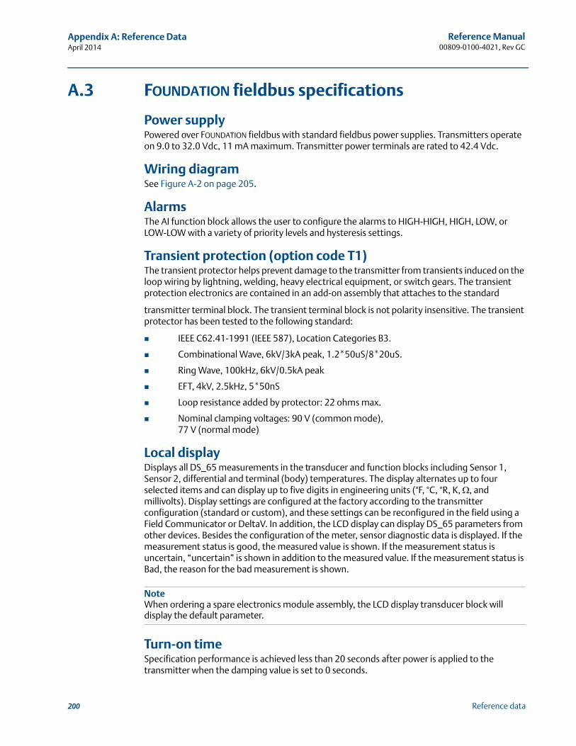
200
Reference Manual00809-0100-4021, Rev GC
Appendix A: Reference DataApril 2014
Reference data
A.3 FOUNDATION fieldbus specifications
Power supply Powered over FOUNDATION fieldbus with standard fieldbus power supplies. Transmitters operate on 9.0 to 32.0 Vdc, 11 mA maximum. Transmitter power terminals are rated to 42.4 Vdc.
Wiring diagramSee Figure A-2 on page 205.
AlarmsThe AI function block allows the user to configure the alarms to HIGH-HIGH, HIGH, LOW, or LOW-LOW with a variety of priority levels and hysteresis settings.
Transient protection (option code T1)The transient protector helps prevent damage to the transmitter from transients induced on the loop wiring by lightning, welding, heavy electrical equipment, or switch gears. The transient protection electronics are contained in an add-on assembly that attaches to the standard
transmitter terminal block. The transient terminal block is not polarity insensitive. The transient protector has been tested to the following standard:
IEEE C62.41-1991 (IEEE 587), Location Categories B3.
Combinational Wave, 6kV/3kA peak, 1.2*50uS/8*20uS.
Ring Wave, 100kHz, 6kV/0.5kA peak
EFT, 4kV, 2.5kHz, 5*50nS
Loop resistance added by protector: 22 ohms max.
Nominal clamping voltages: 90 V (common mode), 77 V (normal mode)
Local displayDisplays all DS_65 measurements in the transducer and function blocks including Sensor 1, Sensor 2, differential and terminal (body) temperatures. The display alternates up to four selected items and can display up to five digits in engineering units (°F, °C, °R, K, , and millivolts). Display settings are configured at the factory according to the transmitter configuration (standard or custom), and these settings can be reconfigured in the field using a Field Communicator or DeltaV. In addition, the LCD display can display DS_65 parameters from other devices. Besides the configuration of the meter, sensor diagnostic data is displayed. If the measurement status is good, the measured value is shown. If the measurement status is uncertain, “uncertain” is shown in addition to the measured value. If the measurement status is Bad, the reason for the bad measurement is shown.
NoteWhen ordering a spare electronics module assembly, the LCD display transducer block will display the default parameter.
Turn-on timeSpecification performance is achieved less than 20 seconds after power is applied to the transmitter when the damping value is set to 0 seconds.
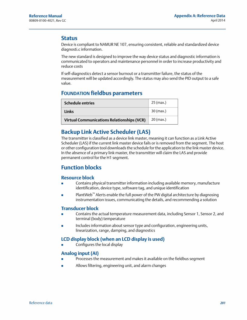
201
Reference Manual 00809-0100-4021, Rev GC
Appendix A: Reference DataApril 2014
Reference data
StatusDevice is compliant to NAMUR NE 107, ensuring consistent, reliable and standardized device diagnosti.c information.
The new standard is designed to improve the way device status and diagnostic information is communicated to operators and maintenance personnel in order to increase productivity and reduce costs
If self-diagnostics detect a sensor burnout or a transmitter failure, the status of the measurement will be updated accordingly. The status may also send the PID output to a safe value.
FOUNDATION fieldbus parameters
Backup Link Active Scheduler (LAS)The transmitter is classified as a device link master, meaning it can function as a Link Active Scheduler (LAS) if the current link master device fails or is removed from the segment. The host or other configuration tool downloads the schedule for the application to the link master device. In the absence of a primary link master, the transmitter will claim the LAS and provide permanent control for the H1 segment.
Function blocks
Resource block Contains physical transmitter information including available memory, manufacture
identification, device type, software tag, and unique identification
PlantWeb™ Alerts enable the full power of the PW digital architecture by diagnosing instrumentation issues, communicating the details, and recommending a solution
Transducer block Contains the actual temperature measurement data, including Sensor 1, Sensor 2, and
terminal (body) temperature
Includes information about sensor type and configuration, engineering units, linearization, range, damping, and diagnostics
LCD display block (when an LCD display is used) Configures the local display
Analog input (AI) Processes the measurement and makes it available on the fieldbus segment
Allows filtering, engineering unit, and alarm changes
Schedule entries 25 (max.)
Links 30 (max.)
Virtual Communications Relationships (VCR) 20 (max.)
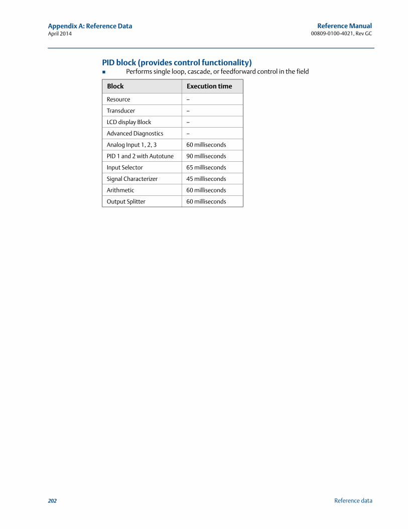
202
Reference Manual00809-0100-4021, Rev GC
Appendix A: Reference DataApril 2014
Reference data
PID block (provides control functionality) Performs single loop, cascade, or feedforward control in the field
Block Execution time
Resource –
Transducer –
LCD display Block –
Advanced Diagnostics –
Analog Input 1, 2, 3 60 milliseconds
PID 1 and 2 with Autotune 90 milliseconds
Input Selector 65 milliseconds
Signal Characterizer 45 milliseconds
Arithmetic 60 milliseconds
Output Splitter 60 milliseconds
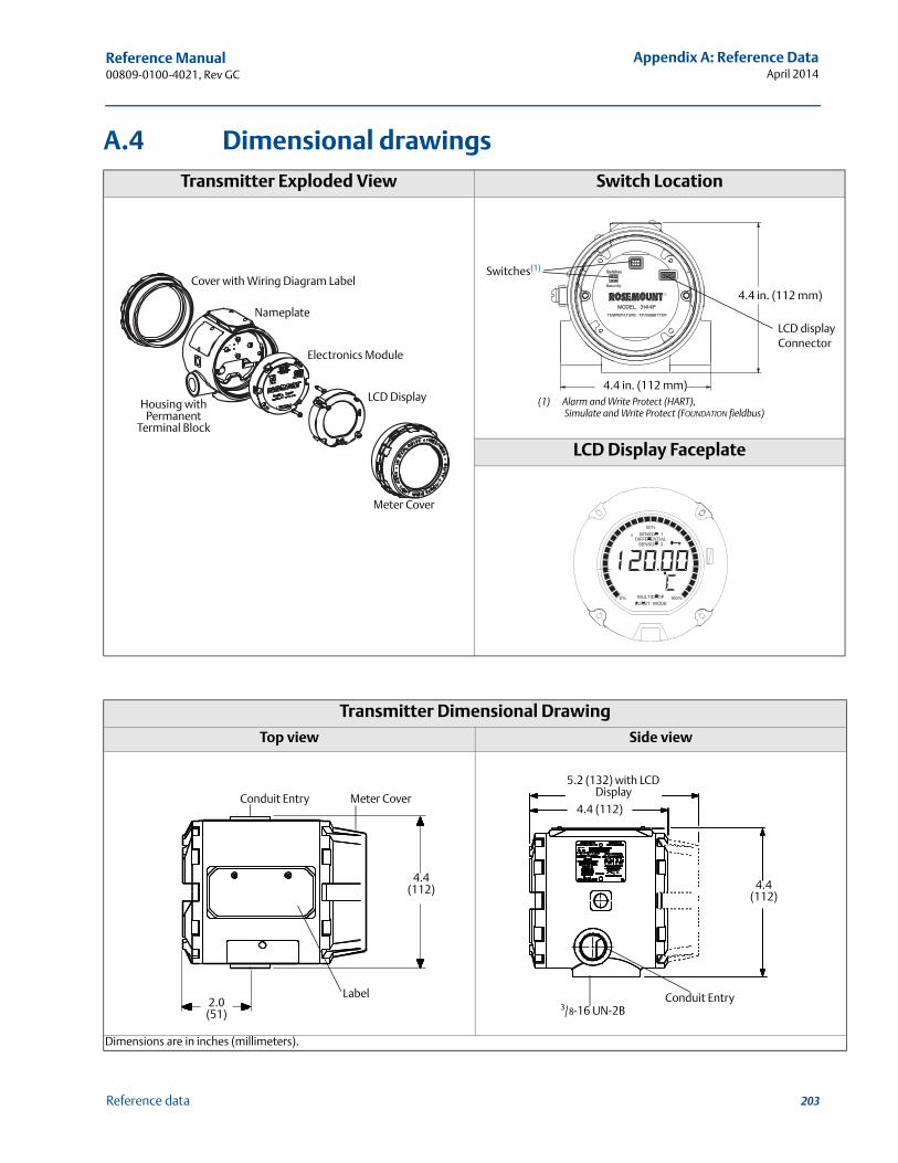
203
Reference Manual 00809-0100-4021, Rev GC
Appendix A: Reference DataApril 2014
Reference data
A.4 Dimensional drawingsTransmitter Exploded View Switch Location
LCD Display Faceplate
Transmitter Dimensional DrawingTop view Side view
Dimensions are in inches (millimeters).
LCD Display
Electronics Module
Nameplate
Meter Cover
Cover with Wiring Diagram Label
Housing with Permanent
Terminal Block
Switches(1)
LCD display Connector
4.4 in. (112 mm)
4.4 in. (112 mm)
(1) Alarm and Write Protect (HART), Simulate and Write Protect (FOUNDATION fieldbus)
2.0 (51)
4.4 (112)
Label
Conduit Entry Meter Cover
5.2 (132) with LCD Display
4.4 (112)
4.4 (112)
Conduit Entry3/8-16 UN-2B
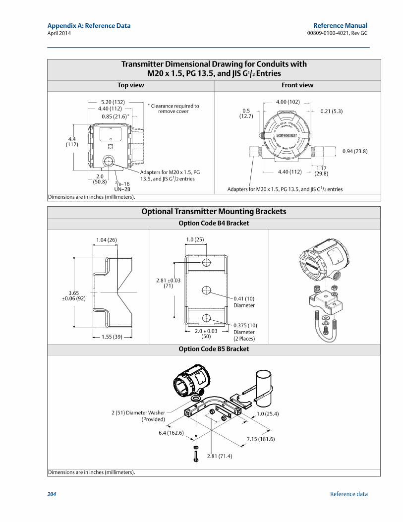
204
Reference Manual00809-0100-4021, Rev GC
Appendix A: Reference DataApril 2014
Reference data
Transmitter Dimensional Drawing for Conduits with M20 x 1.5, PG 13.5, and JIS G1/2 Entries
Top view Front view
Dimensions are in inches (millimeters).
Optional Transmitter Mounting BracketsOption Code B4 Bracket
Option Code B5 Bracket
Dimensions are in inches (millimeters).
4.4 (112)
2.0 (50.8)
5.20 (132)4.40 (112)
0.85 (21.6)*
* Clearance required to remove cover
Adapters for M20 x 1.5, PG 13.5, and JIS G1/2 entries
3/8–16 UN–2B
4.40 (112)1.17
(29.8)
0.94 (23.8)
0.21 (5.3)
4.00 (102)
0.5 (12.7)
Adapters for M20 x 1.5, PG 13.5, and JIS G1/2 entries
1.04 (26)
1.55 (39)
3.65 ±0.06 (92)
1.0 (25)
2.81 ±0.03 (71)
0.41 (10)Diameter
0.375 (10)Diameter(2 Places)
2.0 ± 0.03 (50)
1.0 (25.4)
7.15 (181.6)
2 (51) Diameter Washer(Provided)
6.4 (162.6)
2.81 (71.4)
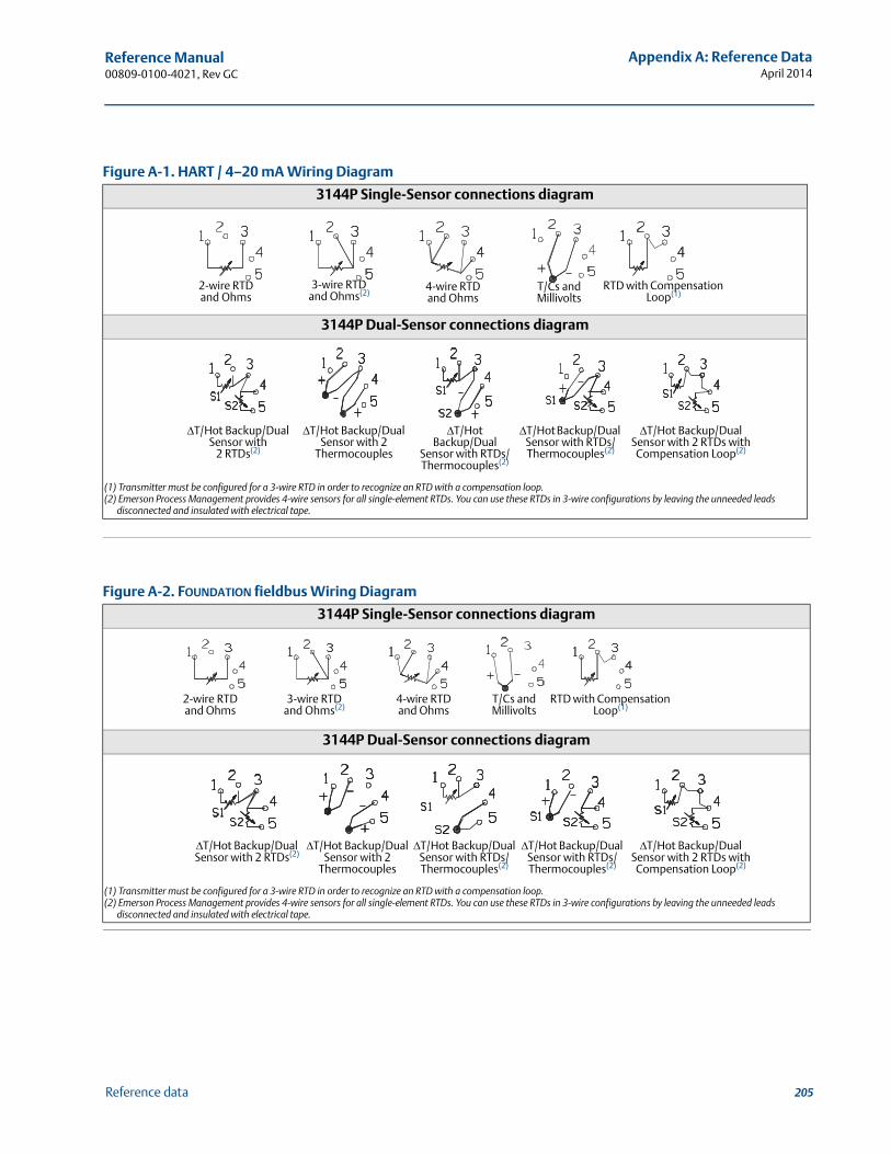
205
Reference Manual 00809-0100-4021, Rev GC
Appendix A: Reference DataApril 2014
Reference data
Figure A-1. HART / 4–20 mA Wiring Diagram
3144P Single-Sensor connections diagram
3144P Dual-Sensor connections diagram
(1) Transmitter must be configured for a 3-wire RTD in order to recognize an RTD with a compensation loop.(2) Emerson Process Management provides 4-wire sensors for all single-element RTDs. You can use these RTDs in 3-wire configurations by leaving the unneeded leads
disconnected and insulated with electrical tape.
Figure A-2. FOUNDATION fieldbus Wiring Diagram
3144P Single-Sensor connections diagram
3144P Dual-Sensor connections diagram
(1) Transmitter must be configured for a 3-wire RTD in order to recognize an RTD with a compensation loop.(2) Emerson Process Management provides 4-wire sensors for all single-element RTDs. You can use these RTDs in 3-wire configurations by leaving the unneeded leads
disconnected and insulated with electrical tape.
4-wire RTD and Ohms
T/Cs and Millivolts
RTD with Compensation Loop(1)
2-wire RTD and Ohms
3-wire RTD and Ohms(2)
T/Hot Backup/Dual Sensor with
2 RTDs(2)
T/Hot Backup/Dual Sensor with 2
Thermocouples
T/Hot Backup/Dual Sensor with RTDs/ Thermocouples(2)
T/Hot Backup/Dual
Sensor with RTDs/ Thermocouples(2)
T/Hot Backup/DualSensor with 2 RTDs with Compensation Loop(2)
4-wire RTD and Ohms
T/Cs and Millivolts
RTD with Compensation Loop(1)
2-wire RTD and Ohms
3-wire RTD and Ohms(2)
T/Hot Backup/Dual Sensor with 2 RTDs(2)
T/Hot Backup/Dual Sensor with 2
Thermocouples
T/Hot Backup/Dual Sensor with RTDs/ Thermocouples(2)
T/Hot Backup/Dual Sensor with RTDs/ Thermocouples(2)
T/Hot Backup/DualSensor with 2 RTDs with Compensation Loop(2)
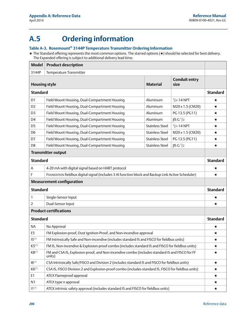
206
Reference Manual00809-0100-4021, Rev GC
Appendix A: Reference DataApril 2014
Reference data
A.5 Ordering informationTable A-3. Rosemount® 3144P Temperature Transmitter Ordering Information★ The Standard offering represents the most common options. The starred options (★) should be selected for best delivery.
The Expanded offering is subject to additional delivery lead time.
Model Product description
3144P Temperature Transmitter
Housing style MaterialConduit entry size
Standard Standard
D1 Field Mount Housing, Dual-Compartment Housing Aluminum 1/2–14 NPT ★
D2 Field Mount Housing, Dual-Compartment Housing Aluminum M20 x 1.5 (CM20) ★
D3 Field Mount Housing, Dual-Compartment Housing Aluminum PG 13.5 (PG11) ★
D4 Field Mount Housing, Dual-Compartment Housing Aluminum JIS G 1/2 ★
D5 Field Mount Housing, Dual-Compartment Housing Stainless Steel 1/2–14 NPT ★
D6 Field Mount Housing, Dual-Compartment Housing Stainless Steel M20 x 1.5 (CM20) ★
D7 Field Mount Housing, Dual-Compartment Housing Stainless Steel PG 13.5 (PG11) ★
D8 Field Mount Housing, Dual-Compartment Housing Stainless Steel JIS G 1/2 ★
Transmitter output
Standard Standard
A 4-20 mA with digital signal based on HART protocol ★
F FOUNDATION fieldbus digital signal (includes 3 AI function block and Backup Link Active Scheduler) ★
Measurement configuration
Standard Standard
1 Single-Sensor Input ★
2 Dual-Sensor Input ★
Product certifications
Standard Standard
NA No Approval ★
E5 FM Explosion-proof, Dust Ignition-Proof, and Non-incendive approval ★
I5(1) FM Intrinsically Safe and Non-incendive (includes standard IS and FISCO for fieldbus units) ★
K5(1) FM IS, Non-incendive & Explosion-proof combo (includes standard IS and FISCO for fieldbus units) ★
KB(1) FM and CSA IS, Explosion-proof, and Non-incendive combo (includes standard IS and FISCO for FF units)
★
I6(1) CSA Intrinsically Safe/FISCO and Division 2 (includes standard IS and FISCO for fieldbus units) ★
K6(1) CSA IS, FISCO Division 2 and Explosion-proof combo (includes standard IS, FISCO for fieldbus units) ★
E1 ATEX Flameproof approval ★
N1 ATEX type n approval ★
I1(1) ATEX intrinsic safety approval (includes standard IS and FISCO for fieldbus units) ★
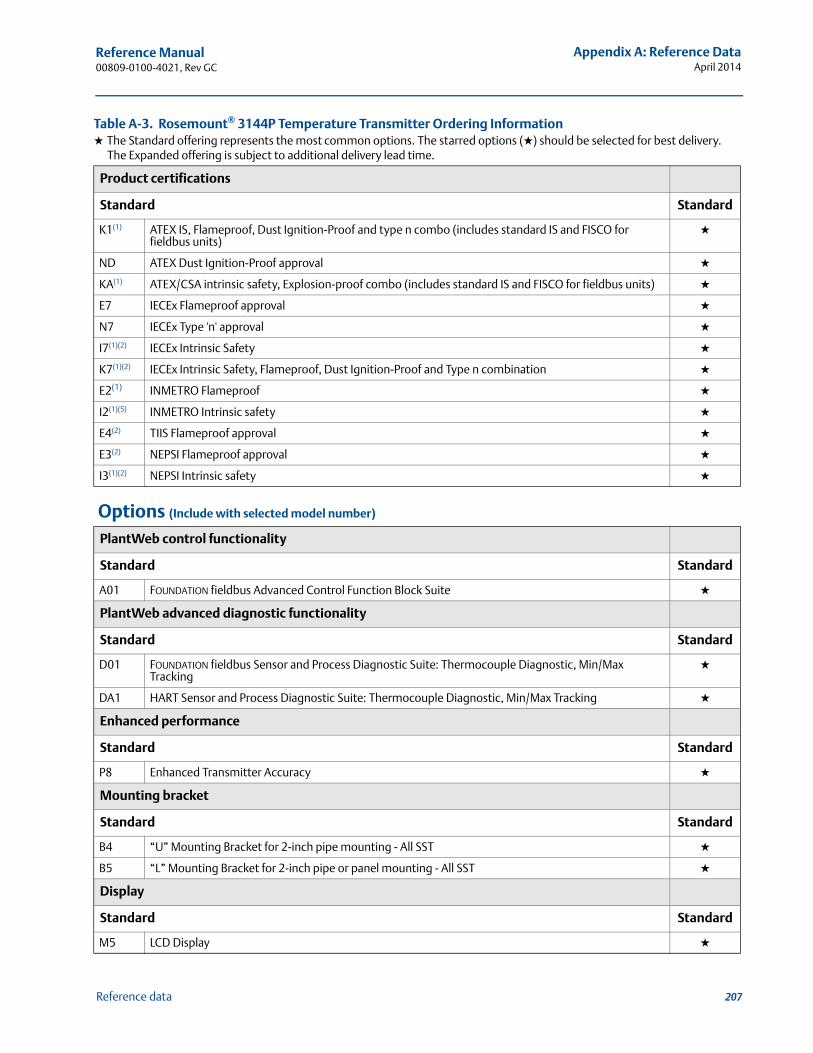
207
Reference Manual 00809-0100-4021, Rev GC
Appendix A: Reference DataApril 2014
Reference data
Product certifications
Standard Standard
K1(1) ATEX IS, Flameproof, Dust Ignition-Proof and type n combo (includes standard IS and FISCO for fieldbus units)
★
ND ATEX Dust Ignition-Proof approval ★
KA(1) ATEX/CSA intrinsic safety, Explosion-proof combo (includes standard IS and FISCO for fieldbus units) ★
E7 IECEx Flameproof approval ★
N7 IECEx Type 'n' approval ★
I7(1)(2) IECEx Intrinsic Safety ★
K7(1)(2) IECEx Intrinsic Safety, Flameproof, Dust Ignition-Proof and Type n combination ★
E2(1) INMETRO Flameproof ★
I2(1)(5) INMETRO Intrinsic safety ★
E4(2) TIIS Flameproof approval ★
E3(2) NEPSI Flameproof approval ★
I3(1)(2) NEPSI Intrinsic safety ★
Options (Include with selected model number)
PlantWeb control functionality
Standard Standard
A01 FOUNDATION fieldbus Advanced Control Function Block Suite ★
PlantWeb advanced diagnostic functionality
Standard Standard
D01 FOUNDATION fieldbus Sensor and Process Diagnostic Suite: Thermocouple Diagnostic, Min/Max Tracking
★
DA1 HART Sensor and Process Diagnostic Suite: Thermocouple Diagnostic, Min/Max Tracking ★
Enhanced performance
Standard Standard
P8 Enhanced Transmitter Accuracy ★
Mounting bracket
Standard Standard
B4 “U” Mounting Bracket for 2-inch pipe mounting - All SST ★
B5 “L” Mounting Bracket for 2-inch pipe or panel mounting - All SST ★
Display
Standard Standard
M5 LCD Display ★
Table A-3. Rosemount® 3144P Temperature Transmitter Ordering Information★ The Standard offering represents the most common options. The starred options (★) should be selected for best delivery.
The Expanded offering is subject to additional delivery lead time.
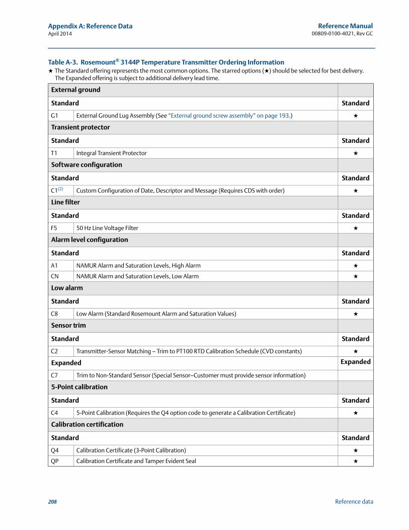
208
Reference Manual00809-0100-4021, Rev GC
Appendix A: Reference DataApril 2014
Reference data
External ground
Standard Standard
G1 External Ground Lug Assembly (See “External ground screw assembly” on page 193.) ★
Transient protector
Standard Standard
T1 Integral Transient Protector ★
Software configuration
Standard Standard
C1(2) Custom Configuration of Date, Descriptor and Message (Requires CDS with order) ★
Line filter
Standard Standard
F5 50 Hz Line Voltage Filter ★
Alarm level configuration
Standard Standard
A1 NAMUR Alarm and Saturation Levels, High Alarm ★
CN NAMUR Alarm and Saturation Levels, Low Alarm ★
Low alarm
Standard Standard
C8 Low Alarm (Standard Rosemount Alarm and Saturation Values) ★
Sensor trim
Standard Standard
C2 Transmitter-Sensor Matching – Trim to PT100 RTD Calibration Schedule (CVD constants) ★
Expanded Expanded
C7 Trim to Non-Standard Sensor (Special Sensor–Customer must provide sensor information)
5-Point calibration
Standard Standard
C4 5-Point Calibration (Requires the Q4 option code to generate a Calibration Certificate) ★
Calibration certification
Standard Standard
Q4 Calibration Certificate (3-Point Calibration) ★
QP Calibration Certificate and Tamper Evident Seal ★
Table A-3. Rosemount® 3144P Temperature Transmitter Ordering Information★ The Standard offering represents the most common options. The starred options (★) should be selected for best delivery.
The Expanded offering is subject to additional delivery lead time.
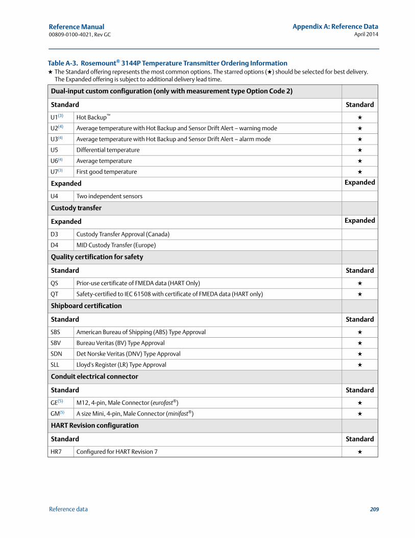
209
Reference Manual 00809-0100-4021, Rev GC
Appendix A: Reference DataApril 2014
Reference data
Dual-input custom configuration (only with measurement type Option Code 2)
Standard Standard
U1(3) Hot Backup™ ★
U2(4) Average temperature with Hot Backup and Sensor Drift Alert – warning mode ★
U3(4) Average temperature with Hot Backup and Sensor Drift Alert – alarm mode ★
U5 Differential temperature ★
U6(4) Average temperature ★
U7(3) First good temperature ★
Expanded Expanded
U4 Two independent sensors
Custody transfer
Expanded Expanded
D3 Custody Transfer Approval (Canada)
D4 MID Custody Transfer (Europe)
Quality certification for safety
Standard Standard
QS Prior-use certificate of FMEDA data (HART Only) ★
QT Safety-certified to IEC 61508 with certificate of FMEDA data (HART only) ★
Shipboard certification
Standard Standard
SBS American Bureau of Shipping (ABS) Type Approval ★
SBV Bureau Veritas (BV) Type Approval ★
SDN Det Norske Veritas (DNV) Type Approval ★
SLL Lloyd's Register (LR) Type Approval ★
Conduit electrical connector
Standard Standard
GE(5) M12, 4-pin, Male Connector (eurofast®) ★
GM(5) A size Mini, 4-pin, Male Connector (minifast®) ★
HART Revision configuration
Standard Standard
HR7 Configured for HART Revision 7 ★
Table A-3. Rosemount® 3144P Temperature Transmitter Ordering Information★ The Standard offering represents the most common options. The starred options (★) should be selected for best delivery.
The Expanded offering is subject to additional delivery lead time.
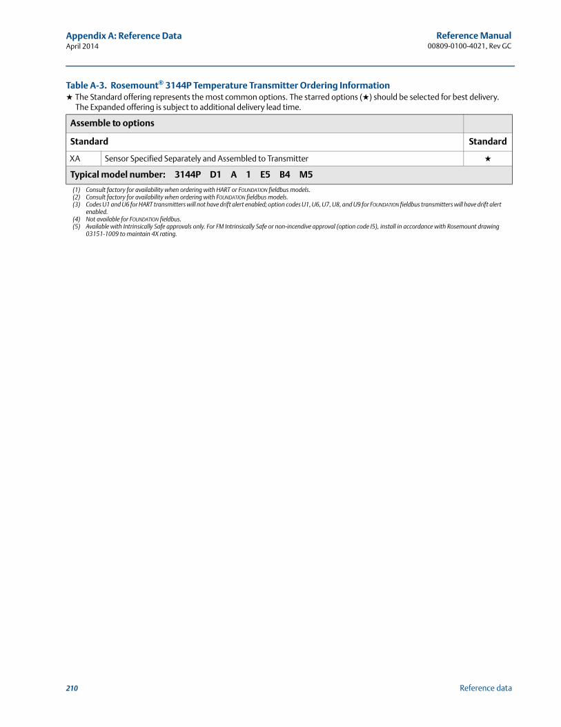
210
Reference Manual00809-0100-4021, Rev GC
Appendix A: Reference DataApril 2014
Reference data
Assemble to options
Standard Standard
XA Sensor Specified Separately and Assembled to Transmitter ★
Typical model number: 3144P D1 A 1 E5 B4 M5
(1) Consult factory for availability when ordering with HART or FOUNDATION fieldbus models.(2) Consult factory for availability when ordering with FOUNDATION fieldbus models.(3) Codes U1 and U6 for HART transmitters will not have drift alert enabled; option codes U1, U6, U7, U8, and U9 for FOUNDATION fieldbus transmitters will have drift alert
enabled.(4) Not available for FOUNDATION fieldbus.(5) Available with Intrinsically Safe approvals only. For FM Intrinsically Safe or non-incendive approval (option code I5), install in accordance with Rosemount drawing
03151-1009 to maintain 4X rating.
Table A-3. Rosemount® 3144P Temperature Transmitter Ordering Information★ The Standard offering represents the most common options. The starred options (★) should be selected for best delivery.
The Expanded offering is subject to additional delivery lead time.
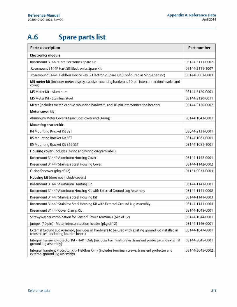
211
Reference Manual 00809-0100-4021, Rev GC
Appendix A: Reference DataApril 2014
Reference data
A.6 Spare parts listParts description Part number
Electronics module
Rosemount 3144P Hart Electronics Spare Kit 03144-3111-0007
Rosemount 3144P Hart SIS Electronics Spare Kit 03144-3111-1007
Rosemount 3144P Fieldbus Device Rev. 2 Electronic Spare Kit (Configured as Single Sensor) 03144-5601-0003
M5 meter kit (Includes meter display, captive mounting hardware, 10-pin interconnection header and cover)
M5 Meter Kit - Aluminum 03144-3120-0001
M5 Meter Kit - Stainless Steel 03144-3120-0011
Meter (includes meter, captive mounting hardware, and 10-pin interconnection header) 03144-3120-0002
Meter cover kit
Aluminum Meter Cover Kit (includes cover and O-ring) 03144-1043-0001
Mounting bracket kit
B4 Mounting Bracket Kit SST 03044-2131-0001
B5 Mounting Bracket Kit SST 03144-1081-0001
B5 Mounting Bracket Kit 316 SST 03144-1081-1001
Housing cover (Includes O-ring and wiring diagram label)
Rosemount 3144P Aluminum Housing Cover 03144-1142-0001
Rosemount 3144P Stainless Steel Housing Cover 03144-1142-0002
O-ring for cover (pkg of 12) 01151-0033-0003
Housing kit (does not include covers)
Rosemount 3144P Aluminum Housing Kit 03144-1141-0001
Rosemount 3144P Aluminum Housing Kit with External Ground Lug Assembly 03144-1141-0002
Rosemount 3144P Stainless Steel Housing Kit 03144-1141-0003
Rosemount 3144P Stainless Steel Housing Kit with External Ground Lug Assembly 03144-1141-0004
Rosemount 3144P Cover Clamp Kit 03144-1048-0001
Screw/Washer combination for Sensor/ Power Terminals (pkg of 12) 03144-1044-0001
Jumper (10 pin) - Meter interconnection header (pkg of 12) 03144-1146-0001
External Ground Lug Assembly (includes all hardware to be used with existing ground lug installed in transmitter - including knurled insert)
03144-1047-0001
Integral Transient Protector Kit - HART Only (includes terminal screws, transient protector and external ground lug assembly)
03144-3045-0001
Integral Transient Protector Kit - Fieldbus Only (includes terminal screws, transient protector and external ground lug assembly)
03144-3045-0002
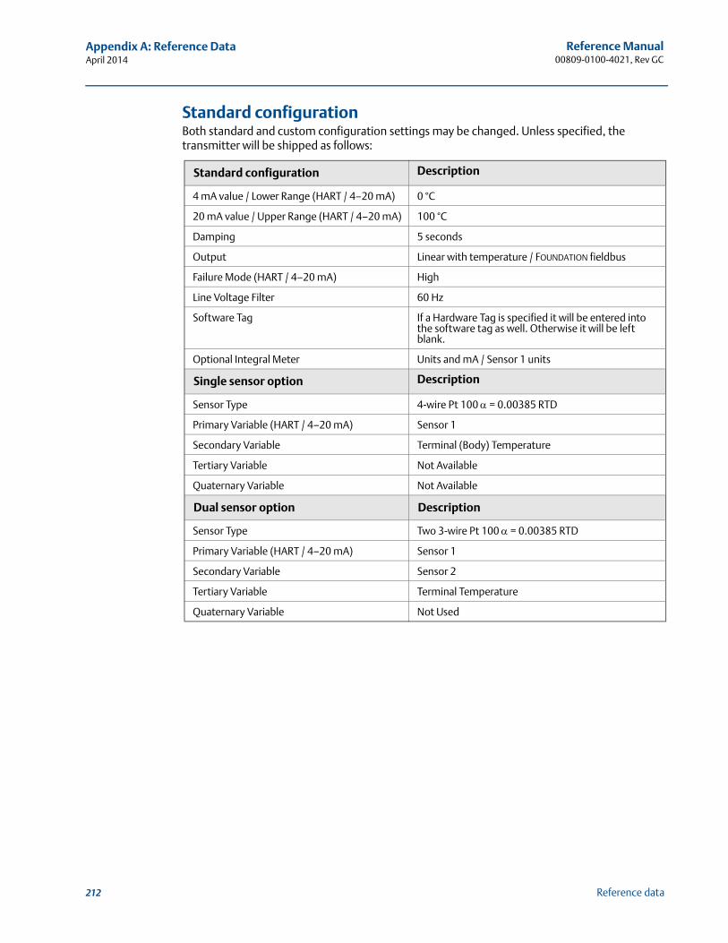
212
Reference Manual00809-0100-4021, Rev GC
Appendix A: Reference DataApril 2014
Reference data
Standard configuration Both standard and custom configuration settings may be changed. Unless specified, the transmitter will be shipped as follows:
Standard configuration Description
4 mA value / Lower Range (HART / 4–20 mA) 0 °C
20 mA value / Upper Range (HART / 4–20 mA) 100 °C
Damping 5 seconds
Output Linear with temperature / FOUNDATION fieldbus
Failure Mode (HART / 4–20 mA) High
Line Voltage Filter 60 Hz
Software Tag If a Hardware Tag is specified it will be entered into the software tag as well. Otherwise it will be left blank.
Optional Integral Meter Units and mA / Sensor 1 units
Single sensor option Description
Sensor Type 4-wire Pt 100 = 0.00385 RTD
Primary Variable (HART / 4–20 mA) Sensor 1
Secondary Variable Terminal (Body) Temperature
Tertiary Variable Not Available
Quaternary Variable Not Available
Dual sensor option Description
Sensor Type Two 3-wire Pt 100 = 0.00385 RTD
Primary Variable (HART / 4–20 mA) Sensor 1
Secondary Variable Sensor 2
Tertiary Variable Terminal Temperature
Quaternary Variable Not Used
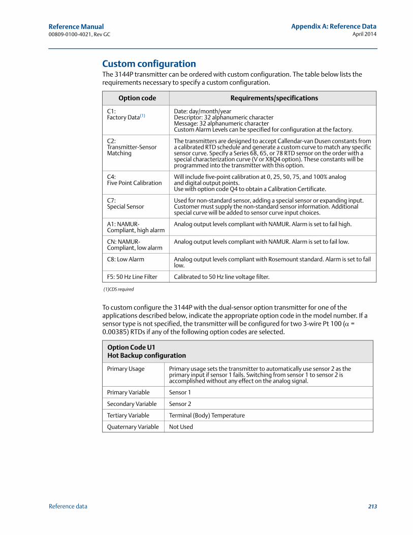
213
Reference Manual 00809-0100-4021, Rev GC
Appendix A: Reference DataApril 2014
Reference data
Custom configurationThe 3144P transmitter can be ordered with custom configuration. The table below lists the requirements necessary to specify a custom configuration.
(1)CDS required
To custom configure the 3144P with the dual-sensor option transmitter for one of the applications described below, indicate the appropriate option code in the model number. If a sensor type is not specified, the transmitter will be configured for two 3-wire Pt 100 ( = 0.00385) RTDs if any of the following option codes are selected.
Option code Requirements/specifications
C1:Factory Data(1)
Date: day/month/yearDescriptor: 32 alphanumeric characterMessage: 32 alphanumeric characterCustom Alarm Levels can be specified for configuration at the factory.
C2:Transmitter-Sensor Matching
The transmitters are designed to accept Callendar-van Dusen constants from a calibrated RTD schedule and generate a custom curve to match any specific sensor curve. Specify a Series 68, 65, or 78 RTD sensor on the order with a special characterization curve (V or X8Q4 option). These constants will be programmed into the transmitter with this option.
C4:Five Point Calibration
Will include five-point calibration at 0, 25, 50, 75, and 100% analog and digital output points.Use with option code Q4 to obtain a Calibration Certificate.
C7:Special Sensor
Used for non-standard sensor, adding a special sensor or expanding input.Customer must supply the non-standard sensor information. Additional special curve will be added to sensor curve input choices.
A1: NAMUR-Compliant, high alarm
Analog output levels compliant with NAMUR. Alarm is set to fail high.
CN: NAMUR-Compliant, low alarm
Analog output levels compliant with NAMUR. Alarm is set to fail low.
C8: Low Alarm Analog output levels compliant with Rosemount standard. Alarm is set to fail low.
F5: 50 Hz Line Filter Calibrated to 50 Hz line voltage filter.
Option Code U1 Hot Backup configuration
Primary Usage Primary usage sets the transmitter to automatically use sensor 2 as the primary input if sensor 1 fails. Switching from sensor 1 to sensor 2 is accomplished without any effect on the analog signal.
Primary Variable Sensor 1
Secondary Variable Sensor 2
Tertiary Variable Terminal (Body) Temperature
Quaternary Variable Not Used
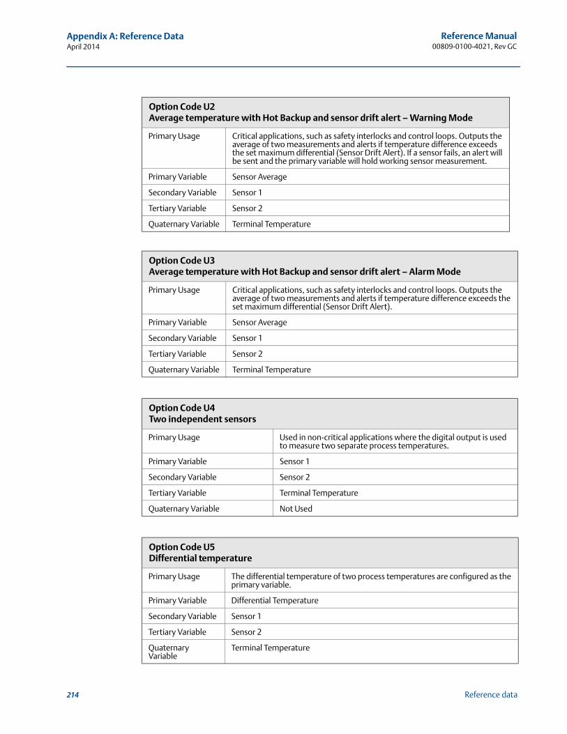
214
Reference Manual00809-0100-4021, Rev GC
Appendix A: Reference DataApril 2014
Reference data
Option Code U2 Average temperature with Hot Backup and sensor drift alert – Warning Mode
Primary Usage Critical applications, such as safety interlocks and control loops. Outputs the average of two measurements and alerts if temperature difference exceeds the set maximum differential (Sensor Drift Alert). If a sensor fails, an alert will be sent and the primary variable will hold working sensor measurement.
Primary Variable Sensor Average
Secondary Variable Sensor 1
Tertiary Variable Sensor 2
Quaternary Variable Terminal Temperature
Option Code U3 Average temperature with Hot Backup and sensor drift alert – Alarm Mode
Primary Usage Critical applications, such as safety interlocks and control loops. Outputs the average of two measurements and alerts if temperature difference exceeds the set maximum differential (Sensor Drift Alert).
Primary Variable Sensor Average
Secondary Variable Sensor 1
Tertiary Variable Sensor 2
Quaternary Variable Terminal Temperature
Option Code U4Two independent sensors
Primary Usage Used in non-critical applications where the digital output is used to measure two separate process temperatures.
Primary Variable Sensor 1
Secondary Variable Sensor 2
Tertiary Variable Terminal Temperature
Quaternary Variable Not Used
Option Code U5Differential temperature
Primary Usage The differential temperature of two process temperatures are configured as the primary variable.
Primary Variable Differential Temperature
Secondary Variable Sensor 1
Tertiary Variable Sensor 2
Quaternary Variable
Terminal Temperature

Reference Manual 00809-0100-4021, Rev GC
Appendix B: Product CertificationsApril 2014
217Product Certifications
Appendix B Product Certifications
Approved Manufacturing Locations . . . . . . . . . . . . . . . . . . . . . . . . . . . . . . . . . . . . . . . . . . . page 217European Directive Information . . . . . . . . . . . . . . . . . . . . . . . . . . . . . . . . . . . . . . . . . . . . . . . page 217Ordinary Location Certification from FM Approvals . . . . . . . . . . . . . . . . . . . . . . . . . . . . . . page 217Installation Drawings . . . . . . . . . . . . . . . . . . . . . . . . . . . . . . . . . . . . . . . . . . . . . . . . . . . . . . . . page 226
B.1 Approved Manufacturing Locations
Rosemount Inc. – Chanhassen, Minnesota, USA
Rosemount Temperature GmbH – Germany
Emerson Process Management Asia Pacific – Singapore
B.2 European Directive Information
A copy of the EC Declaration of Conformity can be found at the end of the Quick Start Guide. The most recent revision of the EC Declaration of Conformity can be found at www.rosemount.com.
B.3 Ordinary Location Certification from FM Approvals
As standard, the transmitter has been examined and tested to determine that the design meets the basic electrical, mechanical, and fire protection requirements by FM Approvals, a nationally recognized test laboratory (NRTL) as accredited by the Federal Occupational Safety and Health Administration (OSHA).
North AmericaE5 FM Explosionproof, Dust-Ignitionproof, and Nonincendive
Certificate: 3012752Standards Used: FM Class 3600: 1998, FM Class 3611: 2004, FM Class 3615: 1989, FM Class 3810: 2005, NEMA-250: 1991, ANSI/ISA 60079-0: 2009, ANSI/ISA 60079-11: 2009Markings: XP CL I, DIV 1, GP A, B, C, D; T5(–50 °C Ta 85 °C); DIP CL II/III, DIV 1, GP E, F, G; T5(–50 °C Ta 75 °C); T6(–50 °C Ta 60 °C); when installed per Rosemount drawing 03144-0320; NI CL I, DIV 2, GP A, B, C, D; T5(–60 °C Ta 75 °C); T6(–60 °C Ta 50 °C); when installed per Rosemount drawing 03144-0321, 03144-5075;
I5 FM Intrinsic Safety and NonincendiveCertificate: 3012752Standards Used: FM Class 3600: 1998, FM Class 3610: 2010, FM Class 3611: 2004, FM Class 3810: 2005, NEMA-250: 1991, ANSI/ISA 60079-0: 2009, ANSI/ISA 60079-11: 2009Markings: IS CL I / II / III, DIV 1, GP A, B, C, D, E, F, G; T4 (–60 °C Ta 60 °C); IS [Entity] CL I, Zone 0, AEx ia IIC T4(–60 °C Ta 60 °C); NI CL I, DIV 2, GP A, B, C, D; T5(–60 °C Ta 75 °C); T6(–60 °C Ta 50 °C); when installed per Rosemount drawing 03144-0321, 03144-5075;
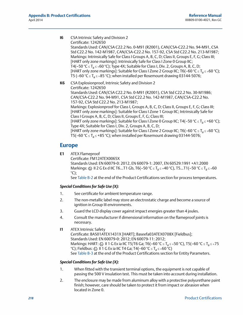
218
Reference Manual00809-0100-4021, Rev GC
Appendix B: Product CertificationsApril 2014
Product Certifications
I6 CSA Intrinsic Safety and Division 2Certificate: 1242650Standards Used: CAN/CSA C22.2 No. 0-M91 (R2001), CAN/CSA-C22.2 No. 94-M91, CSA Std C22.2 No. 142-M1987, CAN/CSA-C22.2 No. 157-92, CSA Std C22.2 No. 213-M1987;Markings: Intrinsically Safe for Class I Groups A, B, C, D; Class II, Groups E, F, G; Class III; [HART only zone markings]: Intrinsically Safe for Class I Zone 0 Group IIC; T4(–50 °C Ta 60 °C); Type 4X; Suitable for Class I, Div. 2, Groups A, B, C, D; [HART only zone markings]: Suitable for Class I Zone 2 Group IIC; T6(–60 °C Ta 60 °C); T5 (–60 °C Ta 85 °C); when installed per Rosemount drawing 03144-5076;
K6 CSA Explosionproof, Intrinsic Safety and Division 2Certificate: 1242650Standards Used: CAN/CSA C22.2 No. 0-M91 (R2001), CSA Std C22.2 No. 30-M1986; CAN/CSA-C22.2 No. 94-M91, CSA Std C22.2 No. 142-M1987, CAN/CSA-C22.2 No. 157-92, CSA Std C22.2 No. 213-M1987;Markings: Explosionproof for Class I, Groups A, B, C, D; Class II, Groups E, F, G; Class III; [HART only zone markings]: Suitable for Class I Zone 1 Group IIC; Intrinsically Safe for Class I Groups A, B, C, D; Class II, Groups E, F, G; Class III; [HART only zone markings]: Suitable for Class I Zone 0 Group IIC; T4(–50 °C Ta +60 °C); Type 4X; Suitable for Class I, Div. 2, Groups A, B, C, D; [HART only zone markings]: Suitable for Class I Zone 2 Group IIC; T6(–60 °C Ta 60 °C); T5(–60 °C Ta +85 °C); when installed per Rosemount drawing 03144-5076;
EuropeE1 ATEX Flameproof
Certificate: FM12ATEX0065XStandards Used: EN 60079-0: 2012, EN 60079-1: 2007, EN 60529:1991 +A1:2000Markings: II 2 G Ex d IIC T6…T1 Gb, T6(–50 °C Ta 40 °C), T5…T1(–50 °C Ta 60 °C);See Table B-2 at the end of the Product Certifications section for process temperatures.
Special Conditions for Safe Use (X):
1. See certificate for ambient temperature range.
2. The non-metallic label may store an electrostatic charge and become a source of ignition in Group III environments.
3. Guard the LCD display cover against impact energies greater than 4 joules.
4. Consult the manufacturer if dimensional information on the flameproof joints is necessary.
I1 ATEX Intrinsic SafetyCertificate: BAS01ATEX1431X [HART]; Baseefa03ATEX0708X [Fieldbus];Standards Used: EN 60079-0: 2012; EN 60079-11: 2012;Markings: HART: II 1 G Ex ia IIC T5/T6 Ga; T6(–60 °C Ta 50 °C), T5(–60 °C Ta 75 °C); Fieldbus: II 1 G Ex ia IIC T4 Ga; T4(–60 °C Ta 60 °C)See Table B-3 at the end of the Product Certifications section for Entity Parameters.
Special Conditions for Safe Use (X):
1. When fitted with the transient terminal options, the equipment is not capable of passing the 500 V insulation test. This must be taken into account during installation.
2. The enclosure may be made from aluminum alloy with a protective polyurethane paint finish; however, care should be taken to protect it from impact or abrasion when located in Zone 0.
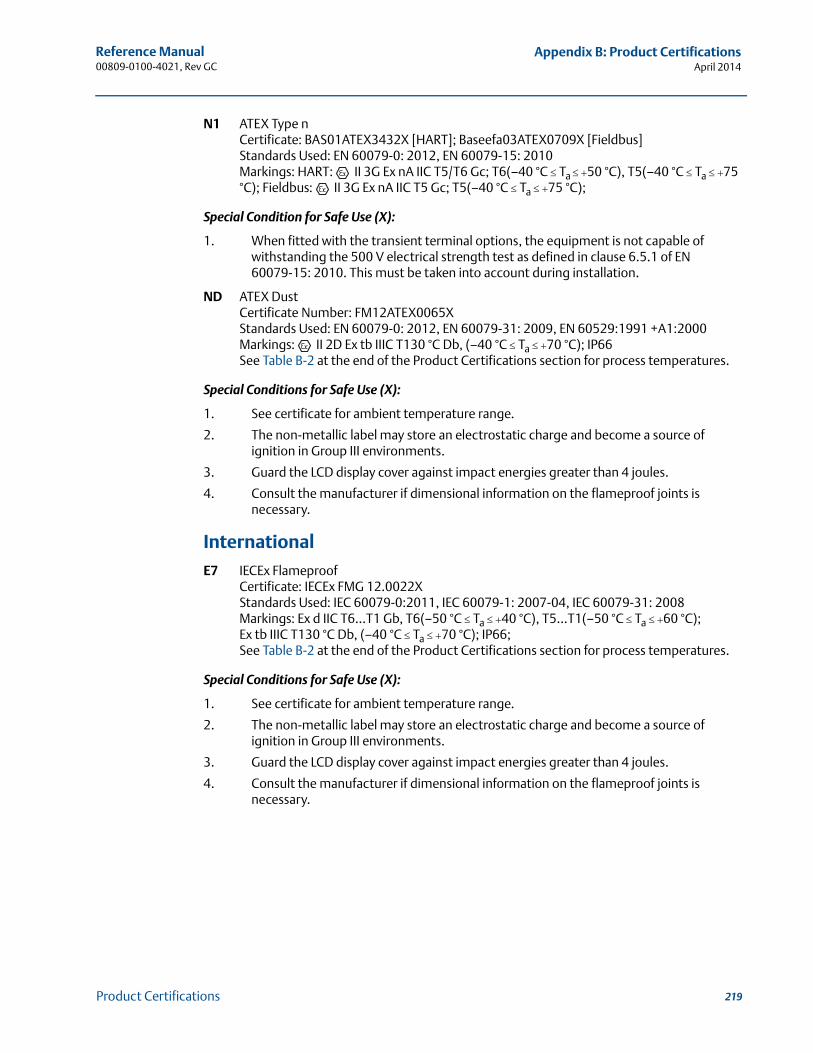
219
Reference Manual 00809-0100-4021, Rev GC
Appendix B: Product CertificationsApril 2014
Product Certifications
N1 ATEX Type nCertificate: BAS01ATEX3432X [HART]; Baseefa03ATEX0709X [Fieldbus]Standards Used: EN 60079-0: 2012, EN 60079-15: 2010Markings: HART: II 3G Ex nA IIC T5/T6 Gc; T6(–40 °C Ta 50 °C), T5(–40 °C Ta 75 °C); Fieldbus: II 3G Ex nA IIC T5 Gc; T5(–40 °C Ta 75 °C);
Special Condition for Safe Use (X):
1. When fitted with the transient terminal options, the equipment is not capable of withstanding the 500 V electrical strength test as defined in clause 6.5.1 of EN 60079-15: 2010. This must be taken into account during installation.
ND ATEX DustCertificate Number: FM12ATEX0065XStandards Used: EN 60079-0: 2012, EN 60079-31: 2009, EN 60529:1991 +A1:2000Markings: II 2D Ex tb IIIC T130 °C Db, (–40 °C Ta 70 °C); IP66See Table B-2 at the end of the Product Certifications section for process temperatures.
Special Conditions for Safe Use (X):
1. See certificate for ambient temperature range.
2. The non-metallic label may store an electrostatic charge and become a source of ignition in Group III environments.
3. Guard the LCD display cover against impact energies greater than 4 joules.
4. Consult the manufacturer if dimensional information on the flameproof joints is necessary.
InternationalE7 IECEx Flameproof
Certificate: IECEx FMG 12.0022XStandards Used: IEC 60079-0:2011, IEC 60079-1: 2007-04, IEC 60079-31: 2008Markings: Ex d IIC T6…T1 Gb, T6(–50 °C Ta 40 °C), T5…T1(–50 °C Ta 60 °C);Ex tb IIIC T130 °C Db, (–40 °C Ta 70 °C); IP66;See Table B-2 at the end of the Product Certifications section for process temperatures.
Special Conditions for Safe Use (X):
1. See certificate for ambient temperature range.
2. The non-metallic label may store an electrostatic charge and become a source of ignition in Group III environments.
3. Guard the LCD display cover against impact energies greater than 4 joules.
4. Consult the manufacturer if dimensional information on the flameproof joints is necessary.
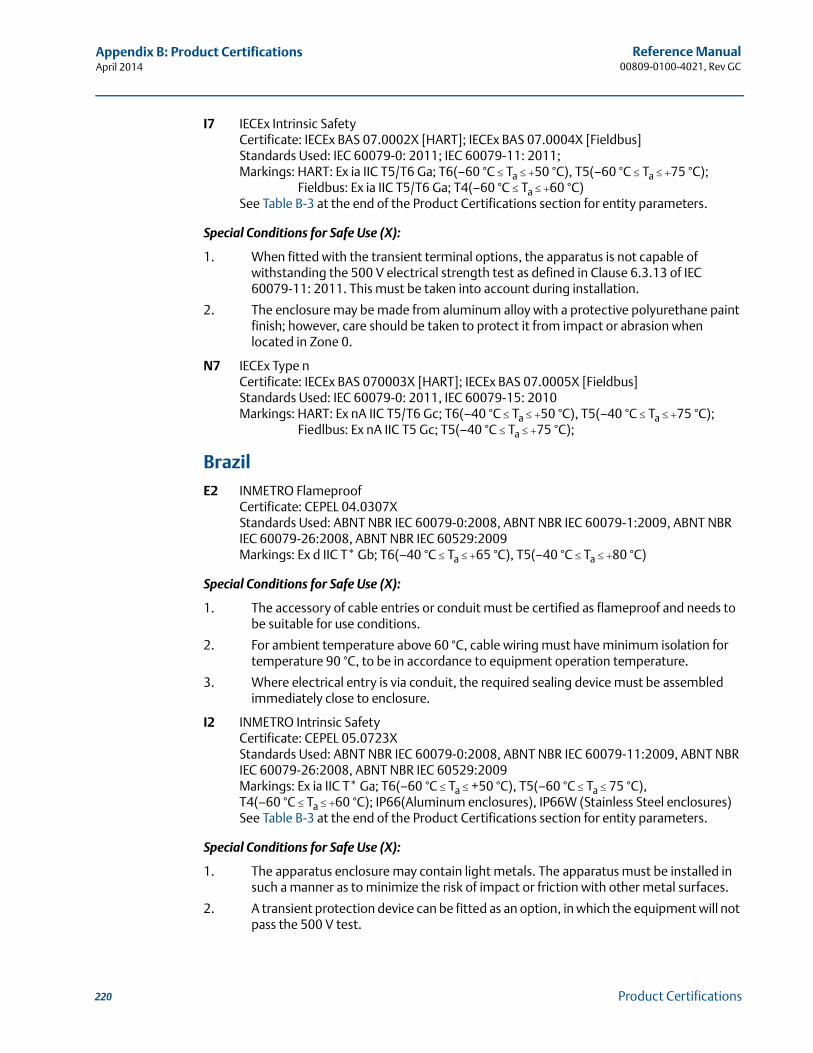
220
Reference Manual00809-0100-4021, Rev GC
Appendix B: Product CertificationsApril 2014
Product Certifications
I7 IECEx Intrinsic Safety Certificate: IECEx BAS 07.0002X [HART]; IECEx BAS 07.0004X [Fieldbus] Standards Used: IEC 60079-0: 2011; IEC 60079-11: 2011;Markings: HART: Ex ia IIC T5/T6 Ga; T6(–60 °C Ta 50 °C), T5(–60 °C Ta 75 °C); Fieldbus: Ex ia IIC T5/T6 Ga; T4(–60 °C Ta 60 °C)See Table B-3 at the end of the Product Certifications section for entity parameters.
Special Conditions for Safe Use (X):
1. When fitted with the transient terminal options, the apparatus is not capable of withstanding the 500 V electrical strength test as defined in Clause 6.3.13 of IEC 60079-11: 2011. This must be taken into account during installation.
2. The enclosure may be made from aluminum alloy with a protective polyurethane paint finish; however, care should be taken to protect it from impact or abrasion when located in Zone 0.
N7 IECEx Type nCertificate: IECEx BAS 070003X [HART]; IECEx BAS 07.0005X [Fieldbus]Standards Used: IEC 60079-0: 2011, IEC 60079-15: 2010Markings: HART: Ex nA IIC T5/T6 Gc; T6(–40 °C Ta 50 °C), T5(–40 °C Ta 75 °C); Fiedlbus: Ex nA IIC T5 Gc; T5(–40 °C Ta 75 °C);
BrazilE2 INMETRO Flameproof
Certificate: CEPEL 04.0307XStandards Used: ABNT NBR IEC 60079-0:2008, ABNT NBR IEC 60079-1:2009, ABNT NBR IEC 60079-26:2008, ABNT NBR IEC 60529:2009Markings: Ex d IIC T* Gb; T6(–40 °C Ta 65 °C), T5(–40 °C Ta 80 °C)
Special Conditions for Safe Use (X):
1. The accessory of cable entries or conduit must be certified as flameproof and needs to be suitable for use conditions.
2. For ambient temperature above 60 °C, cable wiring must have minimum isolation for temperature 90 °C, to be in accordance to equipment operation temperature.
3. Where electrical entry is via conduit, the required sealing device must be assembled immediately close to enclosure.
I2 INMETRO Intrinsic SafetyCertificate: CEPEL 05.0723XStandards Used: ABNT NBR IEC 60079-0:2008, ABNT NBR IEC 60079-11:2009, ABNT NBR IEC 60079-26:2008, ABNT NBR IEC 60529:2009Markings: Ex ia IIC T* Ga; T6(–60 °C Ta +50 °C), T5(–60 °C Ta 75 °C), T4(–60 °C Ta 60 °C); IP66(Aluminum enclosures), IP66W (Stainless Steel enclosures)See Table B-3 at the end of the Product Certifications section for entity parameters.
Special Conditions for Safe Use (X):
1. The apparatus enclosure may contain light metals. The apparatus must be installed in such a manner as to minimize the risk of impact or friction with other metal surfaces.
2. A transient protection device can be fitted as an option, in which the equipment will not pass the 500 V test.
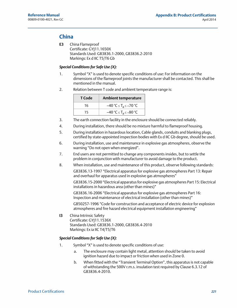
221
Reference Manual 00809-0100-4021, Rev GC
Appendix B: Product CertificationsApril 2014
Product Certifications
China E3 China Flameproof
Certificate: GYJ11.1650XStandards Used: GB3836.1-2000, GB3836.2-2010Markings: Ex d IIC T5/T6 Gb
Special Conditions for Safe Use (X):
1. Symbol “X” is used to denote specific conditions of use: For information on the dimensions of the flameproof joints the manufacturer shall be contacted. This shall be mentioned in the manual.
2. Relation between T code and ambient temperature range is:
3. The earth connection facility in the enclosure should be connected reliably.
4. During installation, there should be no mixture harmful to flameproof housing.
5. During installation in hazardous location, Cable glands, conduits and blanking plugs, certified by state-appointed inspection bodies with Ex d IIC Gb degree, should be used.
6. During installation, use and maintenance in explosive gas atmospheres, observe the warning “Do not open when energized”.
7. End users are not permitted to change any components insides, but to settle the problem in conjunction with manufacturer to avoid damage to the product.
8. When installation, use and maintenance of this product, observe following standards:
GB3836.13-1997 “Electrical apparatus for explosive gas atmospheres Part 13: Repair and overhaul for apparatus used in explosive gas atmospheres”
GB3836.15-2000 “Electrical apparatus for explosive gas atmospheres Part 15: Electrical installations in hazardous area (other than mines)”
GB3836.16-2006 “Electrical apparatus for explosive gas atmospheres Part 16: Inspection and maintenance of electrical installation (other than mines)”
GB50257-1996 “Code for construction and acceptance of electric device for explosion atmospheres and fire hazard electrical equipment installation engineering”
I3 China Intrinsic SafetyCertificate: GYJ11.1536XStandards Used: GB3836.1-2000, GB3836.4-2010Markings: Ex ia IIC T4/T5/T6
Special Conditions for Safe Use (X):
1. Symbol “X” is used to denote specific conditions of use:
a. The enclosure may contain light metal, attention should be taken to avoid ignition hazard due to impact or friction when used in Zone 0.
b. When fitted with the “Transient Terminal Option”, this apparatus is not capable of withstanding the 500V r.m.s. insulation test required by Clause 6.3.12 of GB3836.4-2010.
T Code Ambient temperature
T6 –40 °C Ta 70 °C
T5 –40 °C Ta 80 °C
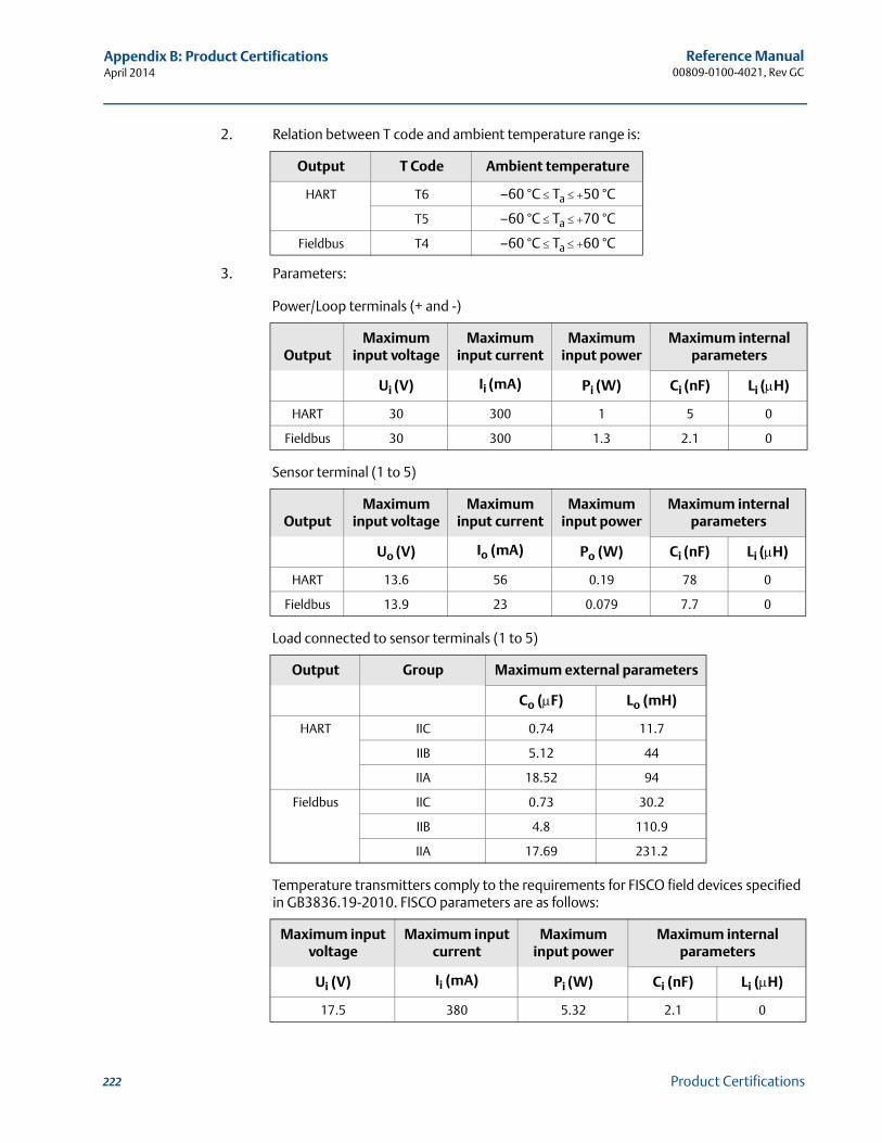
222
Reference Manual00809-0100-4021, Rev GC
Appendix B: Product CertificationsApril 2014
Product Certifications
2. Relation between T code and ambient temperature range is:
3. Parameters:
Power/Loop terminals (+ and -)
Sensor terminal (1 to 5)
Load connected to sensor terminals (1 to 5)
Temperature transmitters comply to the requirements for FISCO field devices specified in GB3836.19-2010. FISCO parameters are as follows:
Output T Code Ambient temperature
HART T6 –60 °C Ta 50 °C
T5 –60 °C Ta 70 °C
Fieldbus T4 –60 °C Ta 60 °C
OutputMaximum
input voltage Maximum
input currentMaximum
input powerMaximum internal
parameters
Ui (V) Ii (mA) Pi (W) Ci (nF) Li (H)
HART 30 300 1 5 0
Fieldbus 30 300 1.3 2.1 0
OutputMaximum
input voltage Maximum
input currentMaximum
input powerMaximum internal
parameters
Uo (V) Io (mA) Po (W) Ci (nF) Li (H)
HART 13.6 56 0.19 78 0
Fieldbus 13.9 23 0.079 7.7 0
Output Group Maximum external parameters
Co (F) Lo (mH)
HART IIC 0.74 11.7
IIB 5.12 44
IIA 18.52 94
Fieldbus IIC 0.73 30.2
IIB 4.8 110.9
IIA 17.69 231.2
Maximum input voltage
Maximum input current
Maximum input power
Maximum internal parameters
Ui (V) Ii (mA) Pi (W) Ci (nF) Li (H)
17.5 380 5.32 2.1 0
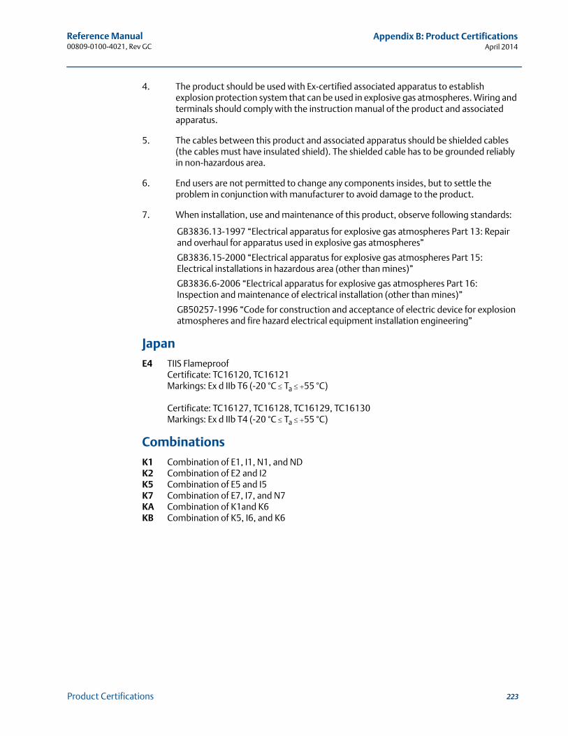
223
Reference Manual 00809-0100-4021, Rev GC
Appendix B: Product CertificationsApril 2014
Product Certifications
4. The product should be used with Ex-certified associated apparatus to establish explosion protection system that can be used in explosive gas atmospheres. Wiring and terminals should comply with the instruction manual of the product and associated apparatus.
5. The cables between this product and associated apparatus should be shielded cables (the cables must have insulated shield). The shielded cable has to be grounded reliably in non-hazardous area.
6. End users are not permitted to change any components insides, but to settle the problem in conjunction with manufacturer to avoid damage to the product.
7. When installation, use and maintenance of this product, observe following standards:
GB3836.13-1997 “Electrical apparatus for explosive gas atmospheres Part 13: Repair and overhaul for apparatus used in explosive gas atmospheres”
GB3836.15-2000 “Electrical apparatus for explosive gas atmospheres Part 15: Electrical installations in hazardous area (other than mines)”
GB3836.6-2006 “Electrical apparatus for explosive gas atmospheres Part 16: Inspection and maintenance of electrical installation (other than mines)”
GB50257-1996 “Code for construction and acceptance of electric device for explosion atmospheres and fire hazard electrical equipment installation engineering”
JapanE4 TIIS Flameproof
Certificate: TC16120, TC16121Markings: Ex d IIb T6 (-20 °C Ta 55 °C)
Certificate: TC16127, TC16128, TC16129, TC16130Markings: Ex d IIb T4 (-20 °C Ta 55 °C)
CombinationsK1 Combination of E1, I1, N1, and NDK2 Combination of E2 and I2K5 Combination of E5 and I5K7 Combination of E7, I7, and N7KA Combination of K1and K6KB Combination of K5, I6, and K6
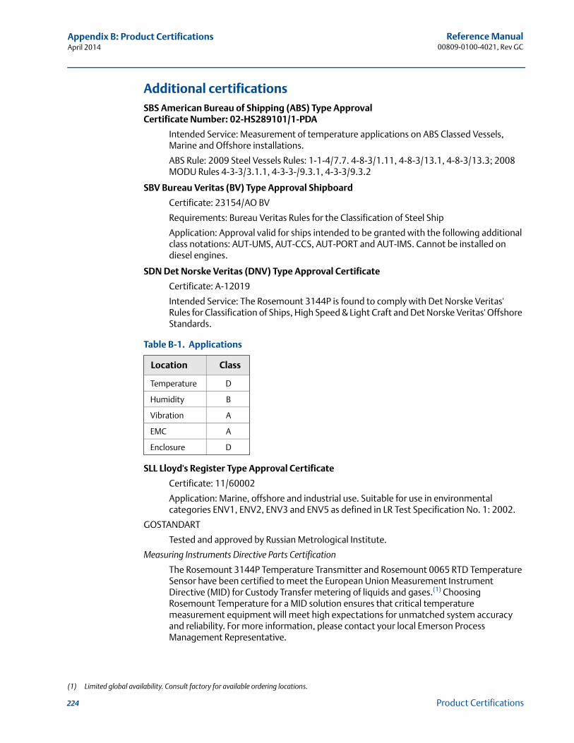
224
Reference Manual00809-0100-4021, Rev GC
Appendix B: Product CertificationsApril 2014
Product Certifications
Additional certificationsSBS American Bureau of Shipping (ABS) Type ApprovalCertificate Number: 02-HS289101/1-PDA
Intended Service: Measurement of temperature applications on ABS Classed Vessels, Marine and Offshore installations.
ABS Rule: 2009 Steel Vessels Rules: 1-1-4/7.7. 4-8-3/1.11, 4-8-3/13.1, 4-8-3/13.3; 2008 MODU Rules 4-3-3/3.1.1, 4-3-3-/9.3.1, 4-3-3/9.3.2
SBV Bureau Veritas (BV) Type Approval Shipboard
Certificate: 23154/AO BV
Requirements: Bureau Veritas Rules for the Classification of Steel Ship
Application: Approval valid for ships intended to be granted with the following additional class notations: AUT-UMS, AUT-CCS, AUT-PORT and AUT-IMS. Cannot be installed on diesel engines.
SDN Det Norske Veritas (DNV) Type Approval Certificate
Certificate: A-12019
Intended Service: The Rosemount 3144P is found to comply with Det Norske Veritas' Rules for Classification of Ships, High Speed & Light Craft and Det Norske Veritas' Offshore Standards.
Table B-1. Applications
SLL Lloyd's Register Type Approval Certificate
Certificate: 11/60002
Application: Marine, offshore and industrial use. Suitable for use in environmental categories ENV1, ENV2, ENV3 and ENV5 as defined in LR Test Specification No. 1: 2002.
GOSTANDART
Tested and approved by Russian Metrological Institute.
Measuring Instruments Directive Parts Certification
The Rosemount 3144P Temperature Transmitter and Rosemount 0065 RTD Temperature Sensor have been certified to meet the European Union Measurement Instrument Directive (MID) for Custody Transfer metering of liquids and gases.(1) Choosing Rosemount Temperature for a MID solution ensures that critical temperature measurement equipment will meet high expectations for unmatched system accuracy and reliability. For more information, please contact your local Emerson Process Management Representative.
Location Class
Temperature D
Humidity B
Vibration A
EMC A
Enclosure D
(1) Limited global availability. Consult factory for available ordering locations.
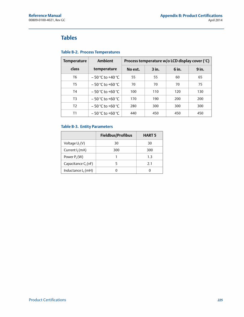
225
Reference Manual 00809-0100-4021, Rev GC
Appendix B: Product CertificationsApril 2014
Product Certifications
Tables
Table B-2. Process Temperatures
Table B-3. Entity Parameters
Temperature Ambient Process temperature w/o LCD display cover (°C)
class temperature No ext. 3 in. 6 in. 9 in.
T6 – 50 °C to +40 °C 55 55 60 65
T5 – 50 °C to +60 °C 70 70 70 75
T4 – 50 °C to +60 °C 100 110 120 130
T3 – 50 °C to +60 °C 170 190 200 200
T2 – 50 °C to +60 °C 280 300 300 300
T1 – 50 °C to +60 °C 440 450 450 450
Fieldbus/Profibus HART 5
Voltage Ui (V) 30 30
Current Ii (mA) 300 300
Power Pi (W) 1 1.3
Capacitance Ci (nF) 5 2.1
Inductance Li (mH) 0 0
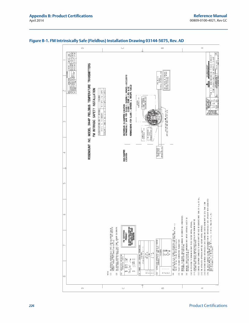
226
Reference Manual00809-0100-4021, Rev GC
Appendix B: Product CertificationsApril 2014
Product Certifications
Figure B-1. FM Intrinsically Safe (Fieldbus) Installation Drawing 03144-5075, Rev. AD
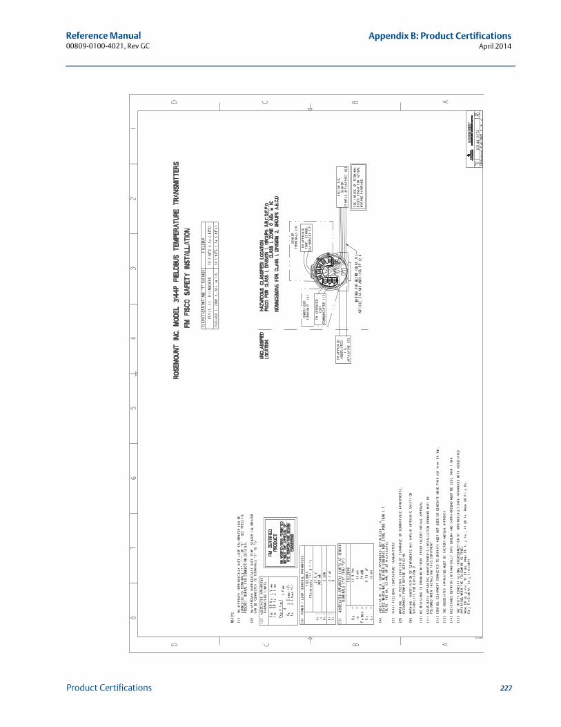
227
Reference Manual 00809-0100-4021, Rev GC
Appendix B: Product CertificationsApril 2014
Product Certifications
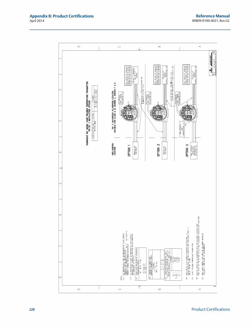
228
Reference Manual00809-0100-4021, Rev GC
Appendix B: Product CertificationsApril 2014
Product Certifications
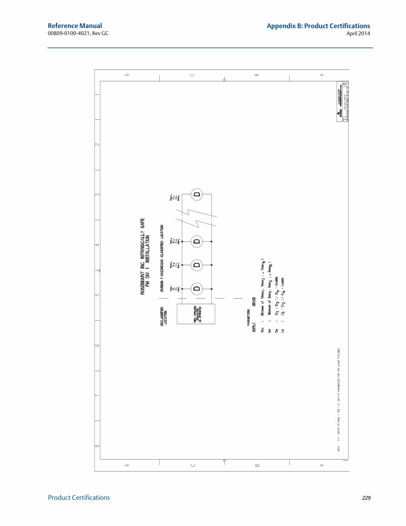
229
Reference Manual 00809-0100-4021, Rev GC
Appendix B: Product CertificationsApril 2014
Product Certifications
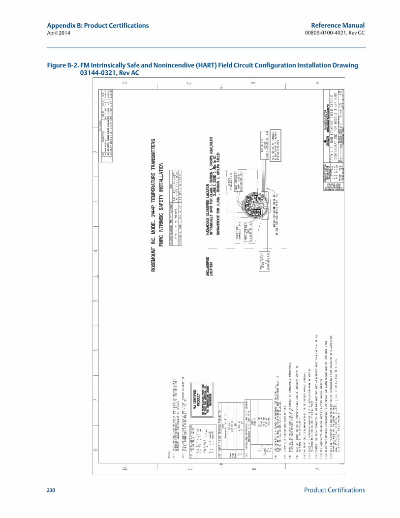
230
Reference Manual00809-0100-4021, Rev GC
Appendix B: Product CertificationsApril 2014
Product Certifications
Figure B-2. FM Intrinsically Safe and Nonincendive (HART) Field Circuit Configuration Installation Drawing 03144-0321, Rev AC
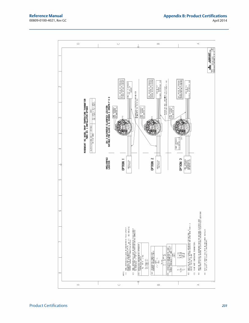
231
Reference Manual 00809-0100-4021, Rev GC
Appendix B: Product CertificationsApril 2014
Product Certifications
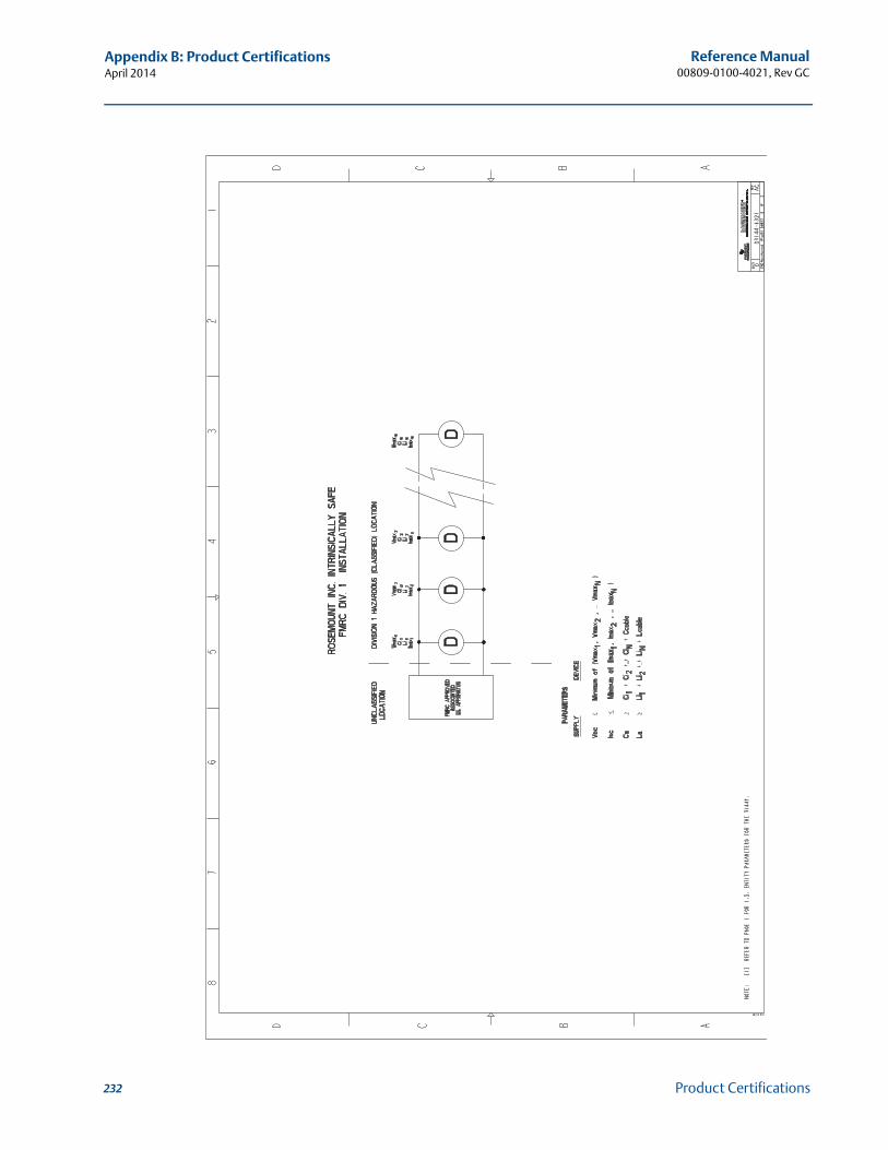
232
Reference Manual00809-0100-4021, Rev GC
Appendix B: Product CertificationsApril 2014
Product Certifications
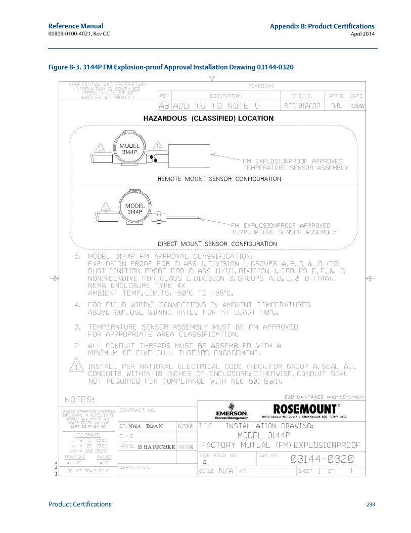
233
Reference Manual 00809-0100-4021, Rev GC
Appendix B: Product CertificationsApril 2014
Product Certifications
Figure B-3. 3144P FM Explosion-proof Approval Installation Drawing 03144-0320
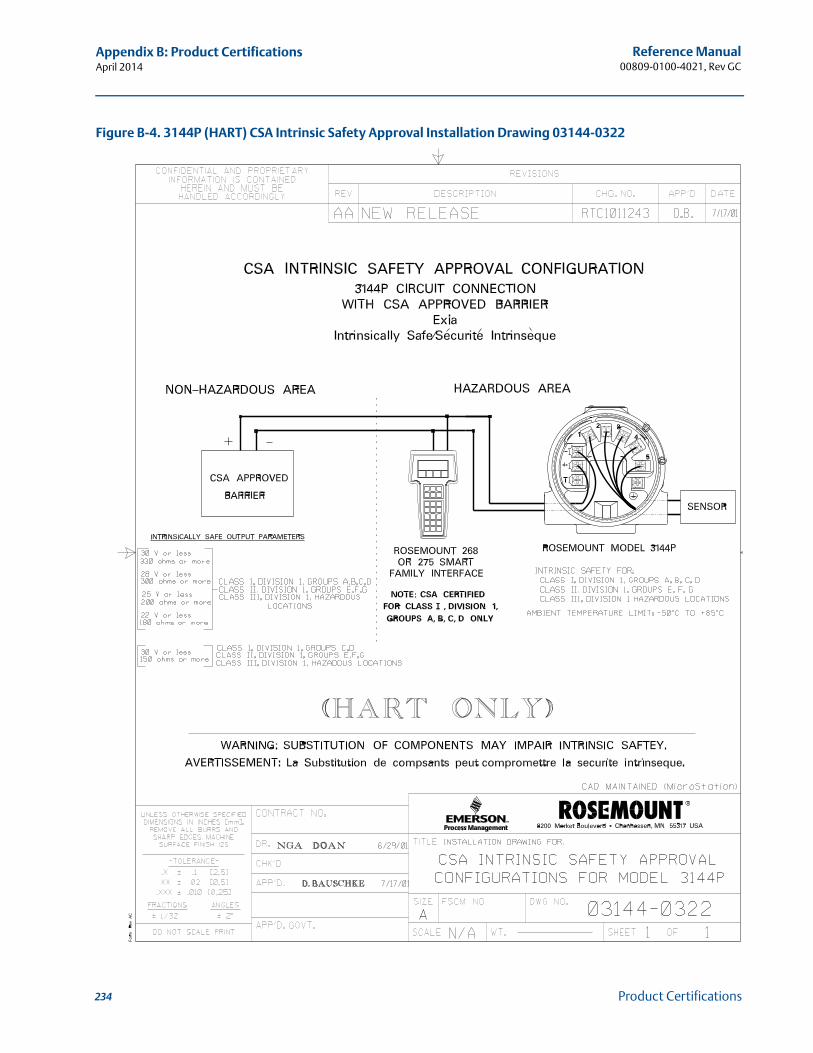
234
Reference Manual00809-0100-4021, Rev GC
Appendix B: Product CertificationsApril 2014
Product Certifications
Figure B-4. 3144P (HART) CSA Intrinsic Safety Approval Installation Drawing 03144-0322
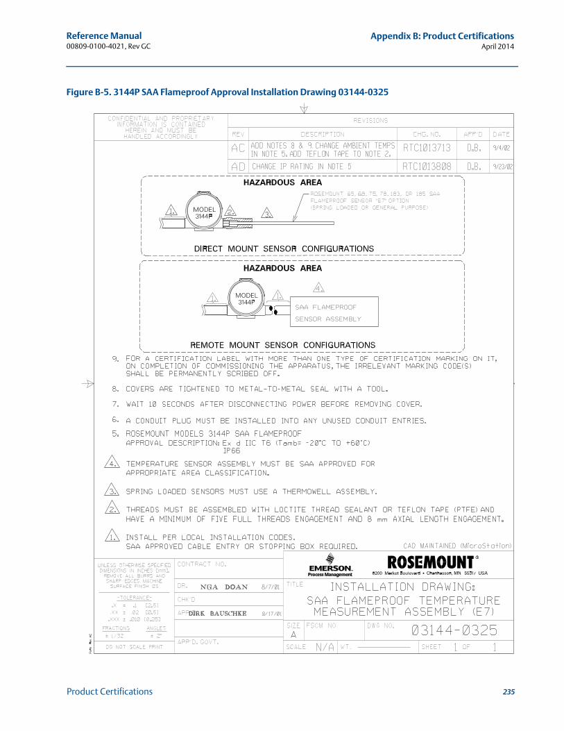
235
Reference Manual 00809-0100-4021, Rev GC
Appendix B: Product CertificationsApril 2014
Product Certifications
Figure B-5. 3144P SAA Flameproof Approval Installation Drawing 03144-0325
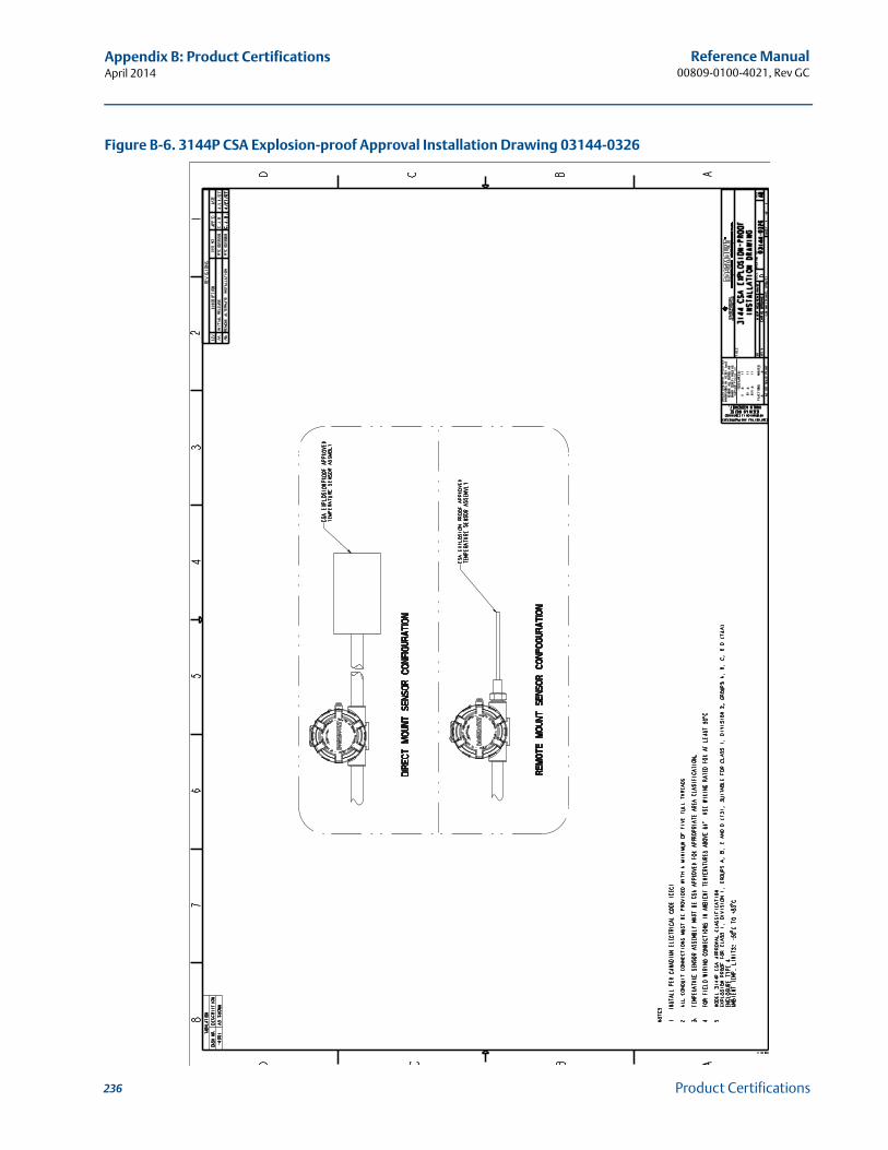
236
Reference Manual00809-0100-4021, Rev GC
Appendix B: Product CertificationsApril 2014
Product Certifications
Figure B-6. 3144P CSA Explosion-proof Approval Installation Drawing 03144-0326
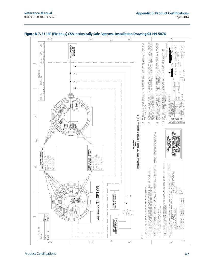
237
Reference Manual 00809-0100-4021, Rev GC
Appendix B: Product CertificationsApril 2014
Product Certifications
Figure B-7. 3144P (Fieldbus) CSA Intrinsically Safe Approval Installation Drawing 03144-5076

238
Reference Manual00809-0100-4021, Rev GC
Appendix B: Product CertificationsApril 2014
Product Certifications
Index-239
Reference Manual 00809-0100-4021, Rev GC
IndexApril 2014
Index
AAlarm Switch. . . . . . . . . . . . . . . . . . . . . . . . . . . . . . . . . . 13Ambient temperature effect . . . . . . . . . . . . . . . . . . . . 192AMS. . . . . . . . . . . . . . . . . . . . . . . . . . . . . . . . . . . . . . . . . 40
Configuration2-Wire RTD Offset . . . . . . . . . . . . . . . . . . . . . . 43Hot Backup Configuration. . . . . . . . . . . . . . . . 46Sensor 1 Serial Number . . . . . . . . . . . . . . . . . . 42Variable Mapping . . . . . . . . . . . . . . . . . . . . . . 41
Device Output ConfigurationAlarm and Saturation . . . . . . . . . . . . . . . . . . . 94Process Variable Damping. . . . . . . . . . . . . . . . 93
HART Tri-Loop . . . . . . . . . . . . . . . . . . . . . . . . . . . . 100Measurement Filtering
Intermittent Threshold . . . . . . . . . . . . . . . . . . 96Master Reset . . . . . . . . . . . . . . . . . . . . . . . . . . 96Open Sensor Holdoff . . . . . . . . . . . . . . . . . . . . 97
Analog Input . . . . . . . . . . . . . . . . . . . . . . . . . . . . . . . . . 155Advanced Features . . . . . . . . . . . . . . . . . . . . . . . . 160
alarm_type . . . . . . . . . . . . . . . . . . . . . . . . . . 160out_d . . . . . . . . . . . . . . . . . . . . . . . . . . . . . . . 160
Configure . . . . . . . . . . . . . . . . . . . . . . . . . . . . . . . 156channel . . . . . . . . . . . . . . . . . . . . . . . . . . . . . 156L_type . . . . . . . . . . . . . . . . . . . . . . . . . . . . . . 156out_scale . . . . . . . . . . . . . . . . . . . . . . . . . . . . 156xd_scale . . . . . . . . . . . . . . . . . . . . . . . . . . . . . 156
Diagnostics . . . . . . . . . . . . . . . . . . . . . . . . . . . . . . 161Filtering . . . . . . . . . . . . . . . . . . . . . . . . . . . . . . . . . 159Process Alarms . . . . . . . . . . . . . . . . . . . . . . . . . . . 159
Alarm Priority. . . . . . . . . . . . . . . . . . . . . . . . . 159Simulation . . . . . . . . . . . . . . . . . . . . . . . . . . . . . . . 155
Manual Mode. . . . . . . . . . . . . . . . . . . . . . . . . 155Simulate. . . . . . . . . . . . . . . . . . . . . . . . . . . . . 155
Status . . . . . . . . . . . . . . . . . . . . . . . . . . . . . . . . . . 160Options . . . . . . . . . . . . . . . . . . . . . . . . . . . . . 160
ApprovalsAustralian . . . . . . . . . . . . . . . . . . . . . . . . . . . . . . . 219Combination . . . . . . . . . . . . . . . . . . . . . . . . . . . . . 224DNV . . . . . . . . . . . . . . . . . . . . . . . . . . . . . . . . . . . . 224GOSTANDART . . . . . . . . . . . . . . . . . . . . . . . . . . . . 224
BBlock Information
Capabilities . . . . . . . . . . . . . . . . . . . . . . . . . . . . . . 142Device Description . . . . . . . . . . . . . . . . . . . . . . . . 140Link Active Scheduler . . . . . . . . . . . . . . . . . . . . . . 141Modes . . . . . . . . . . . . . . . . . . . . . . . . . . . . . . . . . . 140Node Address . . . . . . . . . . . . . . . . . . . . . . . . . . . . 140
CCalibration . . . . . . . . . . . . . . . . . . . . . . . . . . . . . . . . . . 121Check Output
Process Variables . . . . . . . . . . . . . . . . . . . . . . . . . . 40
Commissioning . . . . . . . . . . . . . . . . . . . . . . . . . . . . . . . 10Flowchart . . . . . . . . . . . . . . . . . . . . . . . . . . . . . . . . 10
Configuration2-Wire RTD Offset. . . . . . . . . . . . . . . . . . . . . . . . . . 42Average Temperature. . . . . . . . . . . . . . . . . . . . . . . 43Change Connections . . . . . . . . . . . . . . . . . . . . . . . 41Change Type. . . . . . . . . . . . . . . . . . . . . . . . . . . . . . 41Differential Temperature . . . . . . . . . . . . . . . . . . . . 43Drift Alert Configuration. . . . . . . . . . . . . . . . . . . . . 80Dual Sensor Configuration . . . . . . . . . . . . . . . . . . . 43First-Good Configuration . . . . . . . . . . . . . . . . . . . . 44Output Units . . . . . . . . . . . . . . . . . . . . . . . . . . . . . . 42Sensor 1 Serial Number . . . . . . . . . . . . . . . . . . . . . 42Sensor 2 Serial Number . . . . . . . . . . . . . . . . . . . . . 42Sensor Configuration . . . . . . . . . . . . . . . . . . . . . . . 41Terminal Temperature . . . . . . . . . . . . . . . . . . . . . . 43Variable Mapping . . . . . . . . . . . . . . . . . . . . . . . . . . 41
Considerations . . . . . . . . . . . . . . . . . . . . . . . . . . . . . . . . . .3Corrosive Environments . . . . . . . . . . . . . . . . . . . . . . .4Electrical . . . . . . . . . . . . . . . . . . . . . . . . . . . . . . . . . . .3Environmental . . . . . . . . . . . . . . . . . . . . . . . . . . . . . .3
Temperature Effects . . . . . . . . . . . . . . . . . . . . . .3General . . . . . . . . . . . . . . . . . . . . . . . . . . . . . . . . . . . .3Moist Environments . . . . . . . . . . . . . . . . . . . . . . . . . .4Mounting . . . . . . . . . . . . . . . . . . . . . . . . . . . . . . . . . .5Software Compatibility. . . . . . . . . . . . . . . . . . . . . . . .5
Corrosive Environments. . . . . . . . . . . . . . . . . . . . . . . . . . .4Custom Meter Configuration . . . . . . . . . . . . . . . . . . . . 152
blk_tag_# . . . . . . . . . . . . . . . . . . . . . . . . . . . . . . . 152blk_type_# . . . . . . . . . . . . . . . . . . . . . . . . . . . . . . 153custom_tag_#(1) . . . . . . . . . . . . . . . . . . . . . . . . . 153custom_units_# . . . . . . . . . . . . . . . . . . . . . . . . . . 153Display_param_sel . . . . . . . . . . . . . . . . . . . . . . . . 152param_index_#. . . . . . . . . . . . . . . . . . . . . . . . . . . 153units_type_#. . . . . . . . . . . . . . . . . . . . . . . . . . . . . 153
DDevice Information
Date . . . . . . . . . . . . . . . . . . . . . . . . . . . . . . . . . . . . 95Descriptor . . . . . . . . . . . . . . . . . . . . . . . . . . . . . . . . 95Message . . . . . . . . . . . . . . . . . . . . . . . . . . . . . . . . . 95Tag . . . . . . . . . . . . . . . . . . . . . . . . . . . . . . . . . . . . . 94
Device Output ConfigurationAlarm and Saturation . . . . . . . . . . . . . . . . . . . . . . . 93HART Output . . . . . . . . . . . . . . . . . . . . . . . . . . . . . 94LCD Display Options . . . . . . . . . . . . . . . . . . . . . . . . 94Process Variable Damping . . . . . . . . . . . . . . . . . . . 92PV Range Values . . . . . . . . . . . . . . . . . . . . . . . . . . . 91
Diagnostics and ServiceLoop Test . . . . . . . . . . . . . . . . . . . . . . . . . . . . . . . . 98Test Device . . . . . . . . . . . . . . . . . . . . . . . . . . . . . . . 97
Dimensional drawings . . . . . . . . . . . . . . . . . . . . . . . . . 203
Index
Index-240
Reference Manual00809-0100-4021, Rev GC
IndexApril 2014
Index
EElectrical Considerations . . . . . . . . . . . . . . . . . . . . . . . . . 3Environmental Considerations . . . . . . . . . . . . . . . . . . . . . 3European Installation . . . . . . . . . . . . . . . . . . . . . . . . . . . 16
FFieldbus
See Foundation Fieldbus . . . . . . . . . . . . . . . . . . . . 139Flowchart
Commissioning . . . . . . . . . . . . . . . . . . . . . . . . . . . . 10Installation with Tri-Loop . . . . . . . . . . . . . . . . . . . . 18Troubleshooting . . . . . . . . . . . . . . . . . . . . . . . . . . 170
Foundation FieldbusBlock Information
Capabilities . . . . . . . . . . . . . . . . . . . . . . . . . . 142Device Description . . . . . . . . . . . . . . . . . . . . 140Link Active Scheduler . . . . . . . . . . . . . . . . . . 141Modes . . . . . . . . . . . . . . . . . . . . . . . . . . . . . . 140Node Address . . . . . . . . . . . . . . . . . . . . . . . . 140
Function BlockAnalog Input . . . . . . . . . . . . . . . . . . . . . . . . . 155Information . . . . . . . . . . . . . . . . . . . . . . . . . . 140LCD Transducer Block . . . . . . . . . . . . . . . . . . 152Resource Block . . . . . . . . . . . . . . . . . . . . . . . 144Sensor Transducer Block . . . . . . . . . . . . . . . . 150
LCD DisplayTroubleshooting . . . . . . . . . . . . . . . . . . . . . . 172
Operation . . . . . . . . . . . . . . . . . . . . . . . . . . . . . . . 162Power supply. . . . . . . . . . . . . . . . . . . . . . . . . . . . . . 25SPM Configuration . . . . . . . . . . . . . . . . . . . . . . . . 167Statistical Process Monitoring . . . . . . . . . . . . . . . 164Trim the Transmitter. . . . . . . . . . . . . . . . . . . . . . . 162
Lower Trim. . . . . . . . . . . . . . . . . . . . . . . . . . . 163Recall Factory . . . . . . . . . . . . . . . . . . . . . . . . 163Sensor Calibration . . . . . . . . . . . . . . . . . . . . . 163Upper Trim . . . . . . . . . . . . . . . . . . . . . . . . . . 163
Troubleshooting . . . . . . . . . . . . . . . . . . . . . . . . . . 171Flowchart. . . . . . . . . . . . . . . . . . . . . . . . . . . . 170
Foundations FieldbusSet the switches
With LCD display . . . . . . . . . . . . . . . . . . . . . . . 12Without LCD display . . . . . . . . . . . . . . . . . . . . 12
Function BlockAnalog Input . . . . . . . . . . . . . . . . . . . . . . . . . . . . . 155LCD Transducer Block . . . . . . . . . . . . . . . . . . . . . . 152Resource Block . . . . . . . . . . . . . . . . . . . . . . . . . . . 144Sensor Transducer Block . . . . . . . . . . . . . . . . . . . . 150
Function Block Information . . . . . . . . . . . . . . . . . . . . . 140Functional specifications . . . . . . . . . . . . . . . . . . . . . . . 191
GGeneral Consideration . . . . . . . . . . . . . . . . . . . . . . . . . . . 3Grounding. . . . . . . . . . . . . . . . . . . . . . . . . . . . . . . . . . . . 25
Sensor Shield. . . . . . . . . . . . . . . . . . . . . . . . . . . . . . 25Shield Recommendations. . . . . . . . . . . . . . . . . . . . 26Transmitter Housing . . . . . . . . . . . . . . . . . . . . . . . . 27
HHART
Check OutputProcess Variables. . . . . . . . . . . . . . . . . . . . . . . 40
Configuration2-Wire RTD Offset . . . . . . . . . . . . . . . . . . . . . . 42Average Temperature . . . . . . . . . . . . . . . . . . . 43Change Type. HARTConfigurationChange Connections................................... 41Differential Temperature . . . . . . . . . . . . . . . . 43Drift Alert Configuration . . . . . . . . . . . . . . . . . 80Dual Sensor Configuration . . . . . . . . . . . . . . . 43First-Good Configuration . . . . . . . . . . . . . . . . 44Output Units . . . . . . . . . . . . . . . . . . . . . . . . . . 42Sensor 1 Serial Number. . . . . . . . . . . . . . . . . . 42Sensor 2 Serial Number. . . . . . . . . . . . . . . . . . 42Sensor Configuration . . . . . . . . . . . . . . . . . . . 41Terminal Temperature . . . . . . . . . . . . . . . . . . 43Variable Mapping . . . . . . . . . . . . . . . . . . . . . . 41
Current Loop Connection . . . . . . . . . . . . . . . . . . . . 22Device Information
Date. . . . . . . . . . . . . . . . . . . . . . . . . . . . . . . . . 95Descriptor . . . . . . . . . . . . . . . . . . . . . . . . . . . . 95Message . . . . . . . . . . . . . . . . . . . . . . . . . . . . . 95Tag . . . . . . . . . . . . . . . . . . . . . . . . . . . . . . . . . 94
Device Output ConfigurationAlarm and Saturation . . . . . . . . . . . . . . . . . . . 93HART Output. . . . . . . . . . . . . . . . . . . . . . . . . . 94LCD Display Options . . . . . . . . . . . . . . . . . . . . 94Process Variable Damping . . . . . . . . . . . . . . . 92PV Range Values . . . . . . . . . . . . . . . . . . . . . . . 91
Diagnostics and ServiceLoop Test. . . . . . . . . . . . . . . . . . . . . . . . . . . . . 98Test Device . . . . . . . . . . . . . . . . . . . . . . . . . . . 97
field wiring . . . . . . . . . . . . . . . . . . . . . . . . . . . . . . . 20LCD Display
Troubleshooting . . . . . . . . . . . . . . . . . . . . . . 137Maintenance
Test Terminal . . . . . . . . . . . . . . . . . . . . . . . . 176Measurement Filtering
50/60 Hz Filter. . . . . . . . . . . . . . . . . . . . . . . . . 95Intermittent Sensor Detect. . . . . . . . . . . . . . . 96Intermittent Threshold . . . . . . . . . . . . . . . . . . 96Master Reset . . . . . . . . . . . . . . . . . . . . . . . . . . 96Open Sensor Holdoff. . . . . . . . . . . . . . . . . . . . 97
Power Connections. . . . . . . . . . . . . . . . . . . . . . . . . 22Power supply . . . . . . . . . . . . . . . . . . . . . . . . . . . . . 24Review Configuration Data
Review. . . . . . . . . . . . . . . . . . . . . . . . . . . . . . . 40Safety Instrumented Systems. . . . . . . . . . . . 179, 187Safety Instrumented Systems (SIS)
Installation . . . . . . . . . . . . . . . . . . . . . . . . . . 188Changing Switch Position .......................... 188

Index-241
Reference Manual 00809-0100-4021, Rev GC
IndexApril 2014
Index
Switches..................................................188Overview . . . . . . . . . . . . . . . . . . . . . . . . . . . . 187
Set the switchesWith LCD display . . . . . . . . . . . . . . . . . . . . . . . 11Without LCD display . . . . . . . . . . . . . . . . . . . . 11
Trim the TransmitterActive Calibrator . . . . . . . . . . . . . . . . . . . . . . 124EMF Compensation . . . . . . . . . . . . . . . . . . . . 124Output Trim. . . . . . . . . . . . . . . . . . . . . . . . . . 132Scaled Output Trim . . . . . . . . . . . . . . . .132, 133
Trim the Trasmitter. . . . . . . . . . . . . . . . . . . . . . . . 122Troubleshooting . . . . . . . . . . . . . . . . . . . . . . . . . . 133Updating the Software . . . . . . . . . . . . . . . . . . . . . . 30
HART Tri-Loop. . . . . . . . . . . . . . . . . . . . . . . . . . . . . . . . . 99Set PV Output Order . . . . . . . . . . . . . . . . . . . . . . . . 99Set to Burst Mode . . . . . . . . . . . . . . . . . . . . . . . . . . 99Special Considerations . . . . . . . . . . . . . . . . . . . . . 100
Differential Temperature . . . . . . . . . . . . . . . 100Hot Backup . . . . . . . . . . . . . . . . . . . . . . . . . . 100
Hazardous location certification . . . . . . . . . . . . . . . . . 217
IInstallation . . . . . . . . . . . . . . . . . . . . . . . . . . . . . . . . 10, 15
European . . . . . . . . . . . . . . . . . . . . . . . . . . . . . . . . . 16LCD Display . . . . . . . . . . . . . . . . . . . . . . . . . . . . . . . 18Multichannel . . . . . . . . . . . . . . . . . . . . . . . . . . . . . . 20North American. . . . . . . . . . . . . . . . . . . . . . . . . . . . 15With a 333 Tri-Loop. . . . . . . . . . . . . . . . . . . . . . . . . 17
Installation Flowchart. . . . . . . . . . . . . . . . . . . . . . . . . . . 10
LLCD Display
Installation . . . . . . . . . . . . . . . . . . . . . . . . . . . . . . . 18Troubleshooting . . . . . . . . . . . . . . . . . . . . . .137, 172
LCD Transducer Block . . . . . . . . . . . . . . . . . . . . . . . . . . 152Custom Meter Configuration . . . . . . . . . . . . . . . . 152Diagnostics . . . . . . . . . . . . . . . . . . . . . . . . . . . . . . 153Self Test Procedure . . . . . . . . . . . . . . . . . . . . . . . . 153
Loop to Manual . . . . . . . . . . . . . . . . . . . . . . . . . . . . . . . . 10
MMaintenance. . . . . . . . . . . . . . . . . . . . . . . . . . . . . . . . . 176
Electronics Housing . . . . . . . . . . . . . . . . . . . . . . . 176Remove . . . . . . . . . . . . . . . . . . . . . . . . . . . . . 176Replace . . . . . . . . . . . . . . . . . . . . . . . . . . . . . 177
Sensor Checkout . . . . . . . . . . . . . . . . . . . . . . . . . . 176Test Terminal . . . . . . . . . . . . . . . . . . . . . . . . . . . . 176
Material Return . . . . . . . . . . . . . . . . . . . . . . . . . . . . . . . . . 5Measurement Filtering
50/60 Hz Filter. . . . . . . . . . . . . . . . . . . . . . . . . . . . . 95Intermittent Sensor Detect. . . . . . . . . . . . . . . . . . . 96Intermittent Threshold . . . . . . . . . . . . . . . . . . . . . . 96Master Reset . . . . . . . . . . . . . . . . . . . . . . . . . . . . . . 96Open Sensor Holdoff. . . . . . . . . . . . . . . . . . . . . . . . 97
Moist Environments . . . . . . . . . . . . . . . . . . . . . . . . . . . . . 4
Mounting . . . . . . . . . . . . . . . . . . . . . . . . . . . . . . . . . . . . 13Considerations . . . . . . . . . . . . . . . . . . . . . . . . . . . . . .5Incorrect Conduit Installation. . . . . . . . . . . . . . . . . 14With Drain Seal . . . . . . . . . . . . . . . . . . . . . . . . . . . . 14
Multichannel Installation . . . . . . . . . . . . . . . . . . . . . . . . 20Multidrop CommunicationHART
Multidrop communication . . . . . . . . . . . . . . . . . . . 98
NNorth American Installation . . . . . . . . . . . . . . . . . . . . . . 15
OOperation . . . . . . . . . . . . . . . . . . . . . . . . . . . . . . . . . . . 162
Overview. . . . . . . . . . . . . . . . . . . . . . . . . . . . . . . . 162SPM Configuration . . . . . . . . . . . . . . . . . . . . . . . . 167
SPM_bypass_verification . . . . . . . . . . . . . . . 167SPM_monitoring cycle . . . . . . . . . . . . . . . . . 167SPM#_active . . . . . . . . . . . . . . . . . . . . . . . . . 168SPM#_baseline values. . . . . . . . . . . . . . . . . . 168SPM#_block_tag . . . . . . . . . . . . . . . . . . . . . . 167SPM#_block_type . . . . . . . . . . . . . . . . . . . . . 167SPM#_parameter_index . . . . . . . . . . . . . . . . 167SPM#_threshold . . . . . . . . . . . . . . . . . . . . . . 167SPM#_user command. . . . . . . . . . . . . . . . . . 168
Statistical Process Monitoring . . . . . . . . . . . . . . . 164Configuration Phase . . . . . . . . . . . . . . . . . . . 166Learning Phase . . . . . . . . . . . . . . . . . . . . . . . 166Monitoring Phase . . . . . . . . . . . . . . . . . . . . . 166
Trim the Transmitter . . . . . . . . . . . . . . . . . . . . . . 162Ordering Information. . . . . . . . . . . . . . . . . . . . . . . . . . 206Overview . . . . . . . . . . . . . . . . . . . . . . . . . . . . . . . . . . . . . .1
Manual . . . . . . . . . . . . . . . . . . . . . . . . . . . . . . . . . . . .1Transmitter . . . . . . . . . . . . . . . . . . . . . . . . . . . . . . . . .2
PPerformance specifications . . . . . . . . . . . . . . . . . . . . . 192Power Supply
Foundation Fieldbus . . . . . . . . . . . . . . . . . . . . . . . . 25Grounding. . . . . . . . . . . . . . . . . . . . . . . . . . . . . . . . 25
Sensor Shield. . . . . . . . . . . . . . . . . . . . . . . . . . 25Shield recommendations . . . . . . . . . . . . . . . . 26Transmitter Housing . . . . . . . . . . . . . . . . . . . . 27
HART . . . . . . . . . . . . . . . . . . . . . . . . . . . . . . . . . . . . 24Surges . . . . . . . . . . . . . . . . . . . . . . . . . . . . . . . . . . . 25Transients . . . . . . . . . . . . . . . . . . . . . . . . . . . . . . . . 25
Power supply . . . . . . . . . . . . . . . . . . . . . . . . . . . . 198, 200
Index-242
Reference Manual00809-0100-4021, Rev GC
IndexApril 2014
Index
RResource Block . . . . . . . . . . . . . . . . . . . . . . . . . . . . . . . 144
Diagnostics . . . . . . . . . . . . . . . . . . . . . . . . . . . . . . 149Block Errors . . . . . . . . . . . . . . . . . . . . . . . . . . 149
Features. . . . . . . . . . . . . . . . . . . . . . . . . . . . . . . . . 144Features . . . . . . . . . . . . . . . . . . . . . . . . . . . . . 144features_sel . . . . . . . . . . . . . . . . . . . . . . . . . . 145hard w lock . . . . . . . . . . . . . . . . . . . . . . . . . . 144max_notify . . . . . . . . . . . . . . . . . . . . . . . . . . 145reports . . . . . . . . . . . . . . . . . . . . . . . . . . . . . . 144soft w lock . . . . . . . . . . . . . . . . . . . . . . . . . . . 144Unicode . . . . . . . . . . . . . . . . . . . . . . . . . . . . . 144
Features_selFeatures . . . . . . . . . . . . . . . . . . . . . . . . . . . . . 144features_sel . . . . . . . . . . . . . . . . . . . . . . . . . . 145hard w lock . . . . . . . . . . . . . . . . . . . . . . . . . . 144max_notify . . . . . . . . . . . . . . . . . . . . . . . . . . 145reports . . . . . . . . . . . . . . . . . . . . . . . . . . . . . . 144soft w lock . . . . . . . . . . . . . . . . . . . . . . . . . . . 144Unicode . . . . . . . . . . . . . . . . . . . . . . . . . . . . . 144
PlantWeb AlertsRecommended Actions. . . . . . . . . . . . . . . . . 148
PlantWeb™ Alertsadvisory alarms . . . . . . . . . . . . . . . . . . . . . . . 146failed_alarms . . . . . . . . . . . . . . . . . . . . . . . . . 145maint_alarms . . . . . . . . . . . . . . . . . . . . . . . . 146
Return of Materials . . . . . . . . . . . . . . . . . . . . . . . . . . . . . . 5Review Configuration Data
Review. . . . . . . . . . . . . . . . . . . . . . . . . . . . . . . . . . . 40RFI effect . . . . . . . . . . . . . . . . . . . . . . . . . . . . . . . . . . . . 192
SSafety Instrumented System . . . . . . . . . . . . . . . .179, 187
Installation . . . . . . . . . . . . . . . . . . . . . . . . . . . . . . 188Changing Switch Position . . . . . . . . . . . . . . . 188Switches . . . . . . . . . . . . . . . . . . . . . . . . . . . . 188
Overview . . . . . . . . . . . . . . . . . . . . . . . . . . . . . . . . 187Safety Instrumented Systems
InstallationSwitches . . . . . . . . . . . . . . . . . . . . . . . . . . . . 188
Sensor Transducer Block. . . . . . . . . . . . . . . . . . . . . . . . 150Damping . . . . . . . . . . . . . . . . . . . . . . . . . . . . . . . . 150Diagnostics . . . . . . . . . . . . . . . . . . . . . . . . . . . . . . 151
Set the Switches . . . . . . . . . . . . . . . . . . . . . . . . . . . . . . . 11Alarm. . . . . . . . . . . . . . . . . . . . . . . . . . . . . . . . . . . . 13Foundation Fieldbus
With a LCD display. . . . . . . . . . . . . . . . . . . . . . 12Without a LCD display . . . . . . . . . . . . . . . . . . . 12
HARTWith a LCD display. . . . . . . . . . . . . . . . . . . . . . 11Without a LCD display . . . . . . . . . . . . . . . . . . . 11
locations . . . . . . . . . . . . . . . . . . . . . . . . . . . . . . . . . 12Setting the Loop to Manual . . . . . . . . . . . . . . . . . . . . . . 10Simulate Switch
Set the SwitchesSimulate Switch. . . . . . . . . . . . . . . . . . . . . . . . 13
SISSee Safety Instrumented Systems . . . . . . . . 179, 187
SoftwareCompatibility . . . . . . . . . . . . . . . . . . . . . . . . . . . . . . .5Updating the HART software . . . . . . . . . . . . . . . . . 30
SpecificationsFunctional . . . . . . . . . . . . . . . . . . . . . . . . . . . . . . . 191HART and Foundation Fieldbus . . . . . . . . . . . . . . 191Performance . . . . . . . . . . . . . . . . . . . . . . . . . . . . . 192
SPM Configuration . . . . . . . . . . . . . . . . . . . . . . . . . . . . 167SPM_bypass_verification . . . . . . . . . . . . . . . . . . . 167SPM_monitoring_cycle . . . . . . . . . . . . . . . . . . . . 167SPM#_active . . . . . . . . . . . . . . . . . . . . . . . . . . . . . 168SPM#_baseline values . . . . . . . . . . . . . . . . . . . . . 168SPM#_block_tag. . . . . . . . . . . . . . . . . . . . . . . . . . 167SPM#_block_type. . . . . . . . . . . . . . . . . . . . . . . . . 167SPM#_parameter_index. . . . . . . . . . . . . . . . . . . . 167SPM#_threshold . . . . . . . . . . . . . . . . . . . . . . . . . . 167SPM#_user command . . . . . . . . . . . . . . . . . . . . . 168
Stability . . . . . . . . . . . . . . . . . . . . . . . . . . . . . . . . . . . . 192Statistical Process Monitoring . . . . . . . . . . . . . . . . . . . 164
Configuration Phase . . . . . . . . . . . . . . . . . . . . . . . 166Learning Phase . . . . . . . . . . . . . . . . . . . . . . . . . . . 166Monitoring Phase . . . . . . . . . . . . . . . . . . . . . . . . . 166
TTerminal (Body) Temperature . . . . . . . . . . . . . . . . . . . . 43Trim the Transmitter
HART . . . . . . . . . . . . . . . . . . . . . . . . . . . . . . . . . . . 122Active Calibrator . . . . . . . . . . . . . . . . . . . . . . 124EMF Compensation . . . . . . . . . . . . . . . . . . . . 124Sensor Input Trim HARTTrim the TransmitterSensor Input Trim ..................................... 123Sensor MatchingHARTTrim the TrasmitterSensor Matching ...................................... 125
Trim the TrasmitterFoundation Fieldbus . . . . . . . . . . . . . . . . . . . . . . . 162
Lower Trim . . . . . . . . . . . . . . . . . . . . . . . . . . 163Recall Trim. . . . . . . . . . . . . . . . . . . . . . . . . . . 163Sensor Calibration. . . . . . . . . . . . . . . . . . . . . 163UpperTrim. . . . . . . . . . . . . . . . . . . . . . . . . . . 163
HARTOutput Trim . . . . . . . . . . . . . . . . . . . . . . . . . 132Scaled Output Trim . . . . . . . . . . . . . . . . . . . . 133
Scaled Output Trim. . . . . . . . . . . . . . . . . . . . . . . . 132Troubleshooting
Foundation Fieldbus . . . . . . . . . . . . . . . . . . . . . . . 171LCD Display . . . . . . . . . . . . . . . . . . . . . . . . . . 172
HART . . . . . . . . . . . . . . . . . . . . . . . . . . . . . . . . . . . 133LCD Display . . . . . . . . . . . . . . . . . . . . . . . . . . 137
VVibration effect . . . . . . . . . . . . . . . . . . . . . . . . . . . . . . 192
Index-243
Reference Manual 00809-0100-4021, Rev GC
IndexApril 2014
Index
WWiring . . . . . . . . . . . . . . . . . . . . . . . . . . . . . . . . . . . . . . . 20
Connecting to a Loop . . . . . . . . . . . . . . . . . . . . . . . 22HART
Current Loop Connection . . . . . . . . . . . . . . . . 22Field Wiring . . . . . . . . . . . . . . . . . . . . . . . . . . . 20Power Connections . . . . . . . . . . . . . . . . . . . . . 22
Sensor Connections . . . . . . . . . . . . . . . . . . . . . . . . 23Millivolt Inputs. . . . . . . . . . . . . . . . . . . . . . . . . 24Ohm Inputs . . . . . . . . . . . . . . . . . . . . . . . . . . . 24RTD Inputs . . . . . . . . . . . . . . . . . . . . . . . . . . . . 24Thermocouple Inputs . . . . . . . . . . . . . . . . . . . 24

Index-244
Reference Manual00809-0100-4021, Rev GC
IndexApril 2014
Index


Reference Manual00809-0100-4021, Rev GC
April 2014
Standard Terms and Conditions of Sale can be found at www.rosemount.com/terms_of_saleThe Emerson logo is a trademark and service mark of Emerson Electric Co.Rosemount. the Rosemount logotype, and SMART FAMILY are registered trademarks of Rosemount Inc.Coplanar is a trademark of Rosemount Inc.Halocarbon is a trademark of the Halocarbon Products Corporation.o.Fluorinert is a registered trademark of Minnesota Mining and Manufacturing Company CorporationSyltherm 800 and D.C. 200 are registered trademarks of Dow Corning Corporation.Neobee M-20 is a registered trademark of PVO International, Inc.HART is a registered trademark of the HART Communication Foundation.FOUNDATION fieldbus is a registered trademark of the Fieldbus Foundation.All other marks are the property of their respective owners.
© April 2014 Rosemount, Inc. All rights reserved.
Emerson Process Management GmbH & Co.Argelsrieder Feld 382234 WesslingGermanyTel 49 (8153) 9390Fax 49 (8153) 939172
Emerson Process Management Asia Pacific Private Limited1 Pandan CrescentSingapore 128461T (65) 6777 8211F (65) 6777 [email protected]
Beijing Rosemount Far EastInstrument Co., LimitedNo. 6 North Street, Hepingli, Dong Cheng DistrictBeijing 100013, ChinaT (86) (10) 6428 2233F (86) (10) 6422 8586
Emerson Process ManagementRosemount Measurement8200 Market BoulevardChanhassen MN 55317 USATel (USA) 1 800 999 9307Tel (International) +1 952 906 8888Fax +1 952 906 8889