Rosemount 1199 Diaphragm Seal Systems(Global Offering) - August 2003
84
Product Data Sheet 00813-0100-4016, Rev EA August 2003 Rosemount 1199 www.rosemount.com FOR ROSEMOUNT 3051, 1151, AND 2088 TRANSMITTERS EXPANDED TRANSMITTER USE Extreme hot and cold temperatures Corrosive applications Clogging Sanitary requirements APPLICATIONS Level, Flow, Pressure, Interface, Density Content Specifications . . . . . . . . . . . . . . . . . . . . . . . . . . . . . . . . . . . . . . . . . . . . . . . . . . . . . . page 3 Guide to the Selection of Diaphragm Seals . . . . . . . . . . . . . . . . . . . . . . . . . . . . . . . page 5 Ordering Information . . . . . . . . . . . . . . . . . . . . . . . . . . . . . . . . . . . . . . . . . . . . . . . . . page 9 Diaphragm Seal Connections . . . . . . . . . . . . . . . . . . . . . . . . . . . . . . . . . . . . . . . . . page 10 General Purpose Seal Assemblies . . . . . . . . . . . . . . . . . . . . . . . . . . . . . . . . . . . . . page 16 Sanitary Seal Assemblies . . . . . . . . . . . . . . . . . . . . . . . . . . . . . . . . . . . . . . . . . . . . page 59 General Information. . . . . . . . . . . . . . . . . . . . . . . . . . . . . . . . . . . . . . . . . . . . . . . . . page 71 Configuration Data Sheet . . . . . . . . . . . . . . . . . . . . . . . . . . . . . . . . . . . . . . . . . . . . page 82 Rosemount 1199 Diaphragm Seal Systems (Global Offering)
-
Upload
luppo-luppo -
Category
Documents
-
view
248 -
download
6
description
Guide to the Selection of Diaphragm Seals . . . . . . . . . . . . . . . . . . . . . . . . . . . . . . . page 5 General Purpose Seal Assemblies . . . . . . . . . . . . . . . . . . . . . . . . . . . . . . . . . . . . . page 16
Transcript of Rosemount 1199 Diaphragm Seal Systems(Global Offering) - August 2003
Product Data Sheet00813-0100-4016, Rev EAAugust 2003 Rosemount 1199
www.rosemount.com
FOR ROSEMOUNT 3051, 1151, AND 2088 TRANSMITTERS
EXPANDED TRANSMITTER USE� Extreme hot and cold temperatures
� Corrosive applications
� Clogging
� Sanitary requirements
APPLICATIONS� Level, Flow, Pressure, Interface, Density
ContentSpecifications . . . . . . . . . . . . . . . . . . . . . . . . . . . . . . . . . . . . . . . . . . . . . . . . . . . . . . page 3
Guide to the Selection of Diaphragm Seals . . . . . . . . . . . . . . . . . . . . . . . . . . . . . . . page 5
Ordering Information . . . . . . . . . . . . . . . . . . . . . . . . . . . . . . . . . . . . . . . . . . . . . . . . . page 9
Diaphragm Seal Connections . . . . . . . . . . . . . . . . . . . . . . . . . . . . . . . . . . . . . . . . . page 10
General Purpose Seal Assemblies . . . . . . . . . . . . . . . . . . . . . . . . . . . . . . . . . . . . . page 16
Sanitary Seal Assemblies . . . . . . . . . . . . . . . . . . . . . . . . . . . . . . . . . . . . . . . . . . . . page 59
General Information. . . . . . . . . . . . . . . . . . . . . . . . . . . . . . . . . . . . . . . . . . . . . . . . . page 71
Configuration Data Sheet . . . . . . . . . . . . . . . . . . . . . . . . . . . . . . . . . . . . . . . . . . . . page 82
Rosemount 1199 Diaphragm Seal Systems(Global Offering)
Product Data Sheet00813-0100-4016, Rev EA
August 2003Rosemount 1199
2
THE WORLD'S LARGEST OFFERING
The Rosemount 1199 Diaphragm Seal Systems provide the World's largest product offering to meet your measurement and application requirements. This product data sheet highlights the wide variety of process connection designs, direct mount or capillary systems, and materials of construction available.
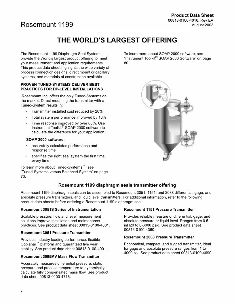
PROVEN TUNED-SYSTEMS DELIVER BEST PRACTICES FOR DP-LEVEL INSTALLATIONS
Rosemount Inc. offers the only Tuned-Systems on the market. Direct mounting the transmitter with a Tuned-System results in:
� Transmitter installed cost reduced by 20%� Total system performance improved by 10%� Time response improved by over 80%. Use
Instrument Toolkit® SOAP 2000 software to calculate the difference for your application.
SOAP 2000 software:� accurately calculates performance and
response time� specifies the right seal system the first time,
every time
To learn more about Tuned-Systems�, see �Tuned-Systems versus Balanced System� on page 73.
To learn more about SOAP 2000 software, see �Instrument Toolkit® SOAP 2000 Software� on page 80.
Rosemount 1199 diaphragm seals transmitter offeringRosemount 1199 diaphragm seals can be assembled to Rosemount 3051, 1151, and 2088 differential, gage, and absolute pressure transmitters, and liquid level transmitters. For additional information, refer to the following product data sheets before ordering a Rosemount 1199 diaphragm seal:
Rosemount 3051S Series of Instrumentation
Scalable pressure, flow and level measurement solutions improve installation and maintenance practices. See product data sheet 00813-0100-4801.
Rosemount 3051 Pressure Transmitter
Provides industry leading performance, flexible Coplanar� platform and guaranteed five year stability. See product data sheet 00813-0100-4001.
Rosemount 3095MV Mass Flow Transmitter
Accurately measures differential pressure, static pressure and process temperature to dynamically calculate fully compensated mass flow. See product data sheet 00813-0100-4716.
Rosemount 1151 Pressure Transmitter
Provides reliable measure of differential, gage, and absolute pressure or liquid level. Ranges from 0.5 inH20 to 0-6000 psig. See product data sheet 00813-0100-4360.
Rosemount 2088 Pressure Transmitter
Economical, compact, and rugged transmitter, ideal for gage and absolute pressure ranges from 1 to 4000 psi. See product data sheet 00813-0100-4690.
Product Data Sheet00813-0100-4016, Rev EAAugust 2003
3
Rosemount 1199
Specifications
SEAL SPECIFICATIONS
Functional Specifications
Sanitary Seal ApprovalsRosemount sanitary seals: Tri-clamp® in-line, tank spud, thin wall spud, Tri-clamp, APC style aseptic, and Cherry Burrell� �I� line, conform to 3-A Sanitary Standards for Sensor and Sensor Fittings and Connections used on Milk and Milk Product Equipment, Number 74-02.The sanitary fill fluids of glycerin (FDA - 21CFR182.1320) and water, and propylene glycol (FDA - 21CFR184.1666) and water are Generally Recognized as Safe (GRAS) in accordance with the FDA Code of Federal Regulations Title 21. The sanitary fill fluid Neobee® M-20 (FDA - 21CFR172.856) is approved as an indirect food additive in accordance with the FDA Code of Federal Regulations Title 21.
NACE StandardNACE (National Association of Corrosion Engineers) standard MR-01-75 defines metallic material requirements for resistance to sulfide stress cracking when exposed to sour environments. Contact your Rosemount representative to aid in selecting the proper materials to meet the NACE standard.
Material TraceabilityMaterial traceability is provided for the diaphragm seal, upper housing, and if applicable, lower housing/flushing connection or diaphragm extension, upon selecting the Transmitter Ordering Option Code Q8.Material traceability for the transmitter/seal system is provided per the DIN EN 10204 3.1.B standard, and is only available for General Assembly Seals.
Performance SpecificationsInstrument Toolkit calculates remote seal system performance and validates model number configuration.
Physical Specifications
Seals, Fill Fluid, and CapillaryCF3M (Cast version of 316L SST, material per ASTM- A743) or CF8M (Cast version of 316 SST, material per ASTM- A743) specifications.
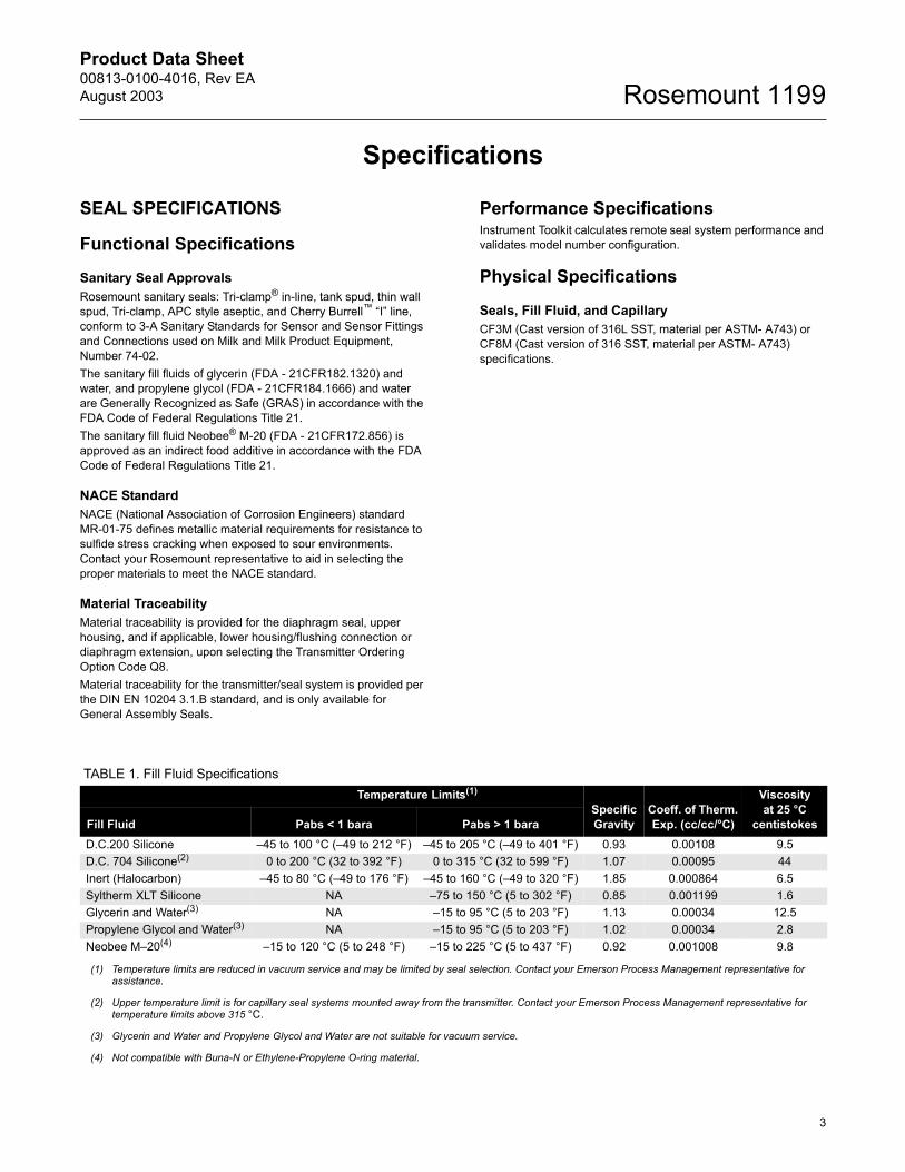
TABLE 1. Fill Fluid SpecificationsTemperature Limits(1)
Specific Gravity
Coeff. of Therm. Exp. (cc/cc/°C)
Viscosity at 25 °C
centistokesFill Fluid Pabs < 1 bara Pabs > 1 baraD.C.200 Silicone �45 to 100 °C (�49 to 212 °F) �45 to 205 °C (�49 to 401 °F) 0.93 0.00108 9.5D.C. 704 Silicone(2) 0 to 200 °C (32 to 392 °F) 0 to 315 °C (32 to 599 °F) 1.07 0.00095 44Inert (Halocarbon) �45 to 80 °C (�49 to 176 °F) �45 to 160 °C (�49 to 320 °F) 1.85 0.000864 6.5Syltherm XLT Silicone NA �75 to 150 °C (5 to 302 °F) 0.85 0.001199 1.6Glycerin and Water(3) NA �15 to 95 °C (5 to 203 °F) 1.13 0.00034 12.5Propylene Glycol and Water(3) NA �15 to 95 °C (5 to 203 °F) 1.02 0.00034 2.8Neobee M�20(4) �15 to 120 °C (5 to 248 °F) �15 to 225 °C (5 to 437 °F) 0.92 0.001008 9.8
(1) Temperature limits are reduced in vacuum service and may be limited by seal selection. Contact your Emerson Process Management representative for assistance.
(2) Upper temperature limit is for capillary seal systems mounted away from the transmitter. Contact your Emerson Process Management representative for temperature limits above 315 °C.
(3) Glycerin and Water and Propylene Glycol and Water are not suitable for vacuum service.
(4) Not compatible with Buna-N or Ethylene-Propylene O-ring material.
Product Data Sheet00813-0100-4016, Rev EA
August 2003Rosemount 1199
4
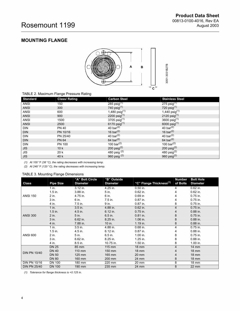
MOUNTING FLANGE
C
BA
3051
-303
1B27
B
TABLE 2. Maximum Flange Pressure RatingStandard Class/ Rating Carbon Steel Stainless SteelANSI 150 285 psig(1) 275 psig(1)
ANSI 300 740 psig(1) 720 psig(1)
ANSI 600 1,480 psig(1) 1,440 psig(1)
ANSI 900 2200 psig(1) 2120 psig(1)
ANSI 1500 3705 psig(1) 3600 psig(1)
ANSI 2500 6170 psig(1) 6000 psig(1)
DIN PN 40 40 bar(2) 40 bar(2) DIN PN 10/16 16 bar(2) 16 bar(2) DIN PN 25/40 40 bar(2) 40 bar(2) DIN PN 64 64 bar(2) 64 bar(2) DIN PN 100 100 bar(2) 100 bar(2) JIS 10 k 200 psig(2) 200 psig(2) JIS 20 k 480 psig (2) 480 psig(2) JIS 40 k 960 psig (2) 960 psig(2)
(1) At 100 °F (38 °C), the rating decreases with increasing temp.(2) At 248 °F (120 °C), the rating decreases with increasing temp.
TABLE 3. Mounting Flange Dimensions
Class Pipe Size�A� Bolt Circle Diameter
�B� Outside Diameter �C� Flange Thickness(1)
Number of Bolts
Bolt Hole Diameter
ANSI 150
1 in. 3.12 in. 4.25 in. 0.50 in. 4 0.62 in.1.5 in. 3.88 in. 5.in. 0.62 in. 4 0.62 in.2 in. 4.75 in. 6.in. 0.69 in 4 0.75 in.3 in. 6.in. 7.5 in. 0.87 in. 4 0.75 in.4 in. 7.5 in. 9.in. 0.87 in. 8 0.75 in.
ANSI 300
1 in. 3.5 in. 4.88 in. 0.62 in. 4 0.75 in.1.5 in. 4.5 in. 6.12 in. 0.75 in. 4 0.88 in.2 in. 5.in. 6.5 in. 0.81 in. 8 0.75 in.3 in. 6.62 in. 8.25 in. 1.06 in. 8 0.88 in.4 in. 7.88 in. 10 in. 1.19 in. 8 0.88 in.
ANSI 600
1 in. 3.5 in. 4.88 in. 0.68 in. 4 0.75 in.1.5 in. 4.5 in. 6.12 in. 0.87 in. 4 0.88 in.2 in. 5.in. 6.5 in. 1.00 in. 8 0.75 in.3 in. 6.62 in. 8.25 in. 1.25 in. 8 0.88 in.4 in. 8.5 in. 10.75 in. 1.50 in. 8 1.00 in.
DIN PN 10/40
DN 25 85 mm 115 mm 18 mm 4 14 mmDN 40 110 mm 150 mm 18 mm 4 18 mmDN 50 125 mm 165 mm 20 mm 4 18 mmDN 80 160 mm 200 mm 24 mm 8 18 mm
DIN PN 10/16 DN 100 180 mm 220 mm 20 mm 8 18 mmDIN PN 25/40 DN 100 190 mm 235 mm 24 mm 8 22 mm
(1) Tolerance for flange thickness is +0.125 in.
Product Data Sheet00813-0100-4016, Rev EAAugust 2003
5
Rosemount 1199
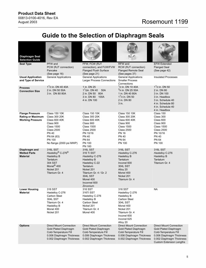
Guide to the Selection of Diaphragm Seals
Diaphragm Seal Selection GuideSeal Type PFW and
PCW (RJT connection) Pancake(See page 16)
FFW, FCW (RJT connection), and FUW/FVW Flanged Flush Surface(See page 21)
RFW andRCW (RJT connection) Flanged Remote Seal(See pages 37)
EFW Extended Flanged Seal (See page 42)
Usual Application and Type of Service
General Applications General ApplicationsLarger Process Connections
General ApplicationsSmaller Process Connections
Insulated Processes
Process Connection Size
11/2 in. DN 40 40A2 in. DN 50 50A3 in. DN 80 80A
1 in. DN 2511/2in. DN 40 50A2 in. DN 50 80A3 in. DN 80 100A4 in. DN 100
1/2 in. DN 10 40A3/4 in. DN 25 50A1 in. DN 40 80A11/2 in. DN 502 in. DN 803 in.
11/2 in. DN 502 in. DN 803 in. DN 1003 in. Headbox3 in. Schedule 404 in. Schedule 804 in. Schedule 404 in. Headbox
Flange Pressure Rating or Maximum Working Pressure
Class 150 10KClass 300 20KClass 600 40KClass 900Class 1500Class 2500PN 40PN 64 (63)PN 100No flange (2000 psi MWP)
Class 150 10KClass 300 20KClass 600 40KClass 900Class 1500Class 2500PN 10/16PN 40PN 64PN 100PN 160
Class 150 10KClass 300 20KClass 600 40KClass 900Class 1500Class 2500PN 16PN 40PN 64PN 100
Class 150Class 300Class 600Class 900Class 1500Class 2500PN 10/16PN 40PN 64PN 100
Diaphragm and Wetted Parts Material
316L SSTHastelloy® C-276®
Hastelloy BTantalum304 SSTMonel® 400Nickel 201Titanium Gr. 4
316L SST316 Ti SSTHastelloy C-276Hastelloy BHastelloy C-22TantalumNickel 201Titanium Gr. 4 / Gr. 2304L SSTMonel 400Inconnel 600 Zirconium
316L SSTHastelloy C-276Hastelloy BTantalumInconel 600304L SSTAlloy 20Monel 400Nickel 201Titanium Gr. 4
316L SSTHastelloy C-276Hastelloy BTantalumTitanium Gr. 4
Lower Housing Material
316 SSTHastelloy C-276Carbon Steel304L SSTTitanium Gr. 4Hastelloy BMonel 400Nickel 201
316 SST316Ti SSTHastelloy C-276Hastelloy BCarbon SteelNickel 201Titanium Gr. 4Monel 400
316 SSTHastelloy C-276Hastelloy BCarbon Steel304L SSTMonel 400Nickel 201Titanium Gr. 4Inconel 600Inconel 625Alloy 20
NA
Options Direct Mount ConnectionGold Plated DiaphragmCold-Temperature Fill0.006 Diaphragm Thickness0.002 Diaphragm Thickness
Direct Mount ConnectionGold Plated DiaphragmCold-Temperature Fill0.006 Diaphragm Thickness0.002 Diaphragm Thickness
Direct Mount ConnectionGold Plated DiaphragmCold-Temperature Fill0.006 Diaphragm Thickness0.002 Diaphragm Thickness
Direct Mount ConnectionGold Plated DiaphragmCold-Temperature Fill0.006 Diaphragm Thickness0.002 Diaphragm ThicknessCustom Extension Lengths
Product Data Sheet00813-0100-4016, Rev EA
August 2003Rosemount 1199
6
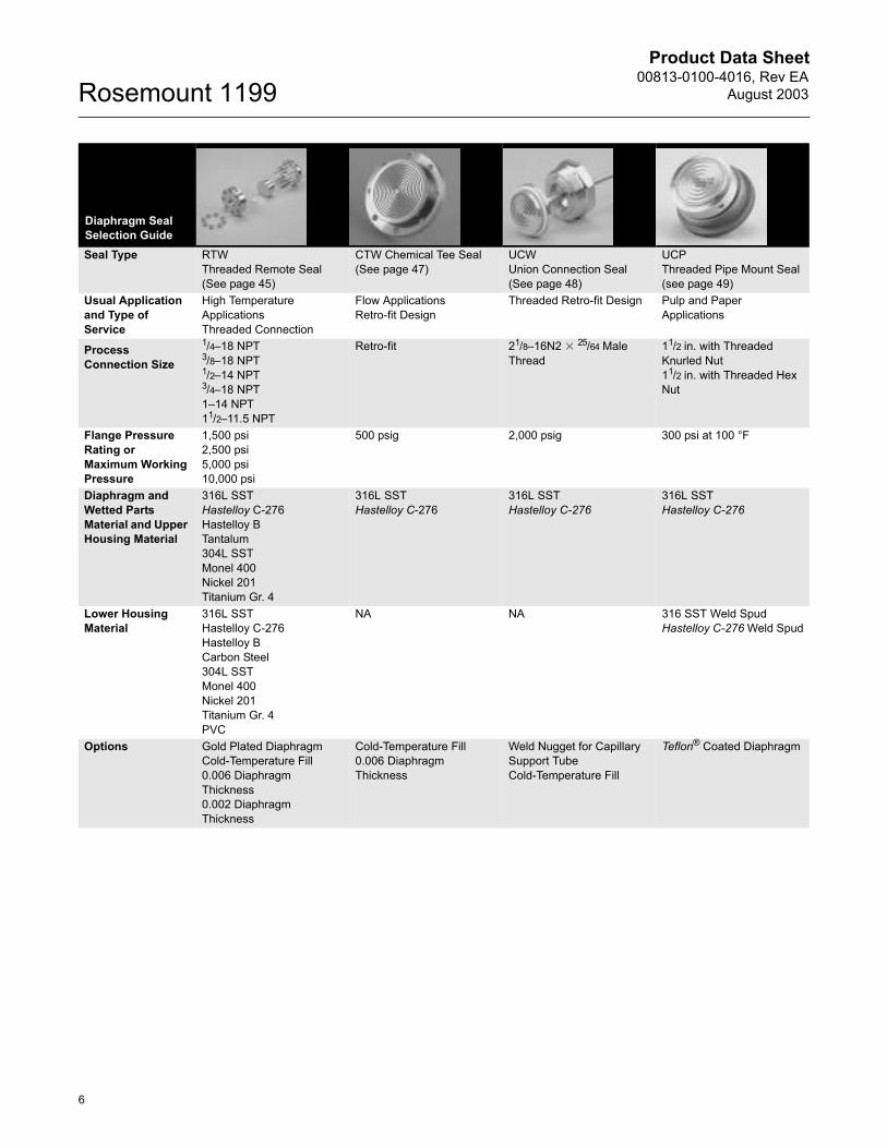
Diaphragm Seal Selection GuideSeal Type RTW
Threaded Remote Seal(See page 45)
CTW Chemical Tee Seal(See page 47)
UCWUnion Connection Seal(See page 48)
UCP Threaded Pipe Mount Seal(see page 49)
Usual Application and Type of Service
High Temperature ApplicationsThreaded Connection
Flow ApplicationsRetro-fit Design
Threaded Retro-fit Design Pulp and Paper Applications
Process Connection Size
1/4�18 NPT3/8�18 NPT1/2�14 NPT3/4�18 NPT1�14 NPT11/2�11.5 NPT
Retro-fit 21/8�16N2 � 25/64 Male Thread
11/2 in. with Threaded Knurled Nut11/2 in. with Threaded Hex Nut
Flange Pressure Rating or Maximum Working Pressure
1,500 psi2,500 psi 5,000 psi 10,000 psi
500 psig 2,000 psig 300 psi at 100 °F
Diaphragm and Wetted Parts Material and Upper Housing Material
316L SSTHastelloy C-276Hastelloy BTantalum304L SSTMonel 400Nickel 201Titanium Gr. 4
316L SSTHastelloy C-276
316L SSTHastelloy C-276
316L SSTHastelloy C-276
Lower Housing Material
316L SSTHastelloy C-276Hastelloy BCarbon Steel304L SSTMonel 400Nickel 201Titanium Gr. 4PVC
NA NA 316 SST Weld SpudHastelloy C-276 Weld Spud
Options Gold Plated DiaphragmCold-Temperature Fill0.006 Diaphragm Thickness0.002 Diaphragm Thickness
Cold-Temperature Fill0.006 Diaphragm Thickness
Weld Nugget for Capillary Support TubeCold-Temperature Fill
Teflon® Coated Diaphragm
Product Data Sheet00813-0100-4016, Rev EAAugust 2003
7
Rosemount 1199
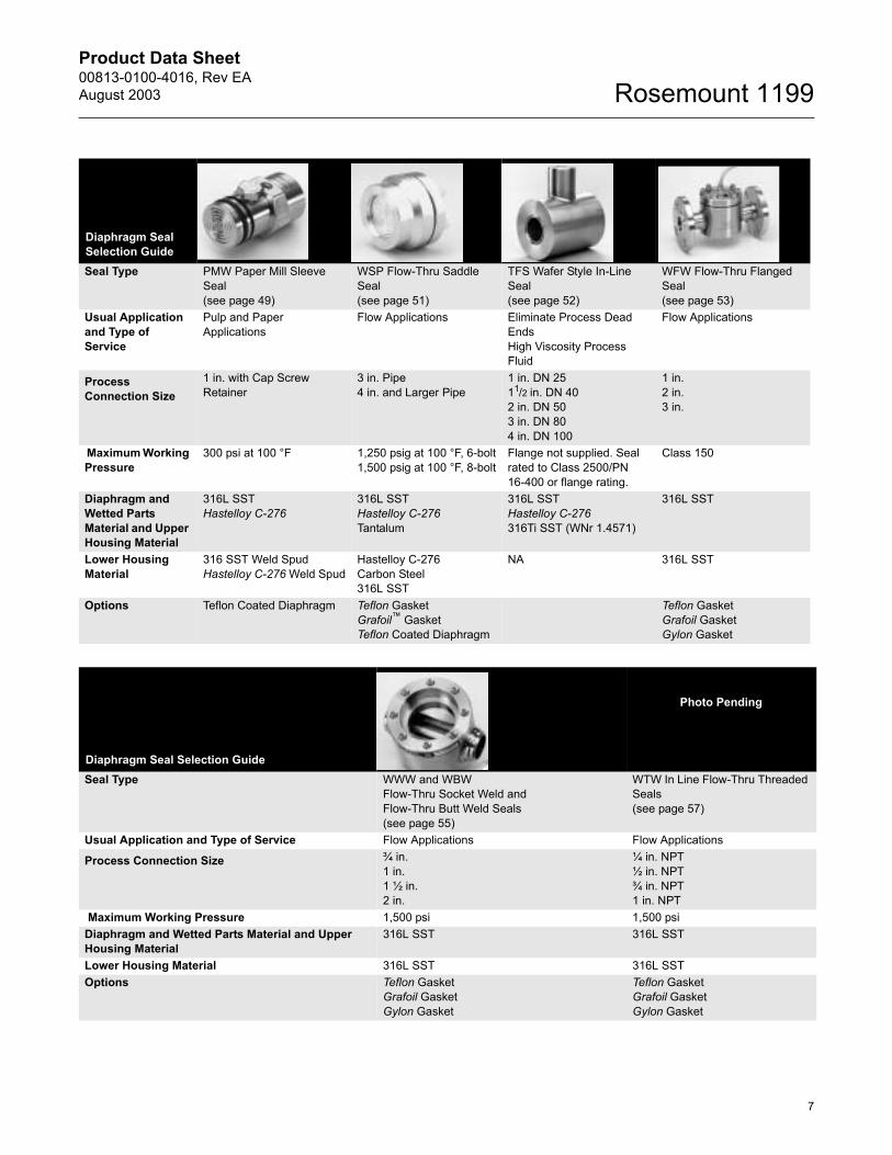
Diaphragm Seal Selection GuideSeal Type PMW Paper Mill Sleeve
Seal(see page 49)
WSP Flow-Thru Saddle Seal(see page 51)
TFS Wafer Style In-Line Seal(see page 52)
WFW Flow-Thru Flanged Seal(see page 53)
Usual Application and Type of Service
Pulp and Paper Applications
Flow Applications Eliminate Process Dead EndsHigh Viscosity Process Fluid
Flow Applications
Process Connection Size
1 in. with Cap Screw Retainer
3 in. Pipe4 in. and Larger Pipe
1 in. DN 2511/2 in. DN 402 in. DN 503 in. DN 804 in. DN 100
1 in.2 in.3 in.
Maximum Working Pressure
300 psi at 100 °F 1,250 psig at 100 °F, 6-bolt1,500 psig at 100 °F, 8-bolt
Flange not supplied. Seal rated to Class 2500/PN 16-400 or flange rating.
Class 150
Diaphragm and Wetted Parts Material and Upper Housing Material
316L SSTHastelloy C-276
316L SSTHastelloy C-276Tantalum
316L SSTHastelloy C-276316Ti SST (WNr 1.4571)
316L SST
Lower Housing Material
316 SST Weld SpudHastelloy C-276 Weld Spud
Hastelloy C-276Carbon Steel316L SST
NA 316L SST
Options Teflon Coated Diaphragm Teflon GasketGrafoil� GasketTeflon Coated Diaphragm
Teflon GasketGrafoil GasketGylon Gasket
Diaphragm Seal Selection GuideSeal Type WWW and WBW
Flow-Thru Socket Weld and Flow-Thru Butt Weld Seals(see page 55)
WTW In Line Flow-Thru Threaded Seals(see page 57)
Usual Application and Type of Service Flow Applications Flow Applications
Process Connection Size ¾ in.1 in.1 ½ in.2 in.
¼ in. NPT½ in. NPT¾ in. NPT1 in. NPT
Maximum Working Pressure 1,500 psi 1,500 psi Diaphragm and Wetted Parts Material and Upper Housing Material
316L SST 316L SST
Lower Housing Material 316L SST 316L SSTOptions Teflon Gasket
Grafoil GasketGylon Gasket
Teflon GasketGrafoil GasketGylon Gasket
Photo Pending

Product Data Sheet00813-0100-4016, Rev EA
August 2003Rosemount 1199
8
Sanitary Seal Selection GuideSeal Type VCS Sanitary In-Line
Tri-Clamp Connection(see page 59)
SCW Sanitary Tri-Clamp Seal(see page 60)
SSW Sanitary Tank Spud Seal(see page 62)
STW Sanitary Thin Wall Tank Spud Seal(see page 64)
Usual Application and Type of Service
Sanitary Flow Sanitary Sanitary Sanitary
Process Connection Size
1 in.11/2 in.2 in.3 in.4 in.
11/2 in.2 in.21/2 in.3 in.4 in.
(see page 44) (see page 46)
Maximum Working Pressure
580 psi see Table 36 on page 61 600 psig 600 psig
Diaphragm and Wetted Parts Material and Upper Housing Material
316L SST316Ti SST (WNr 1.4571)
316L SSTHastelloy C-276
316L SSTHastelloy C-276
316L SSTHastelloy C-276
Options Material TraceabilityCold-Temperature Fill20 µin. (0.5 µm) Ra finish15 µin. (0.375 µm) Ra finishElectropolishing
High Pressure Clamp20 µin. (0.5 µm) Ra finish15 µin. (0.375 µm) Ra finish10 µin. (0.25 µm) Ra finishElectropolishing
2 in. Extension6 in. ExtensionTank Spud20 µin. (0.5 µm) Ra finish15 µin. (0.375 µm) Ra finishElectropolishing
Tank Spud20 µin. (0.5 µm) Ra finish15 µin. (0.375 µm) Ra finishElectropolishing
Sanitary Seal Selection GuideSeal Type SHP Cherry-Burrell Seal
(see page 65)SAP Aseptic (APC) Style Seal(see page 66)
SLS, SMS, SFS, and SRS Sanitary Seals(see page 67)
MLS, MMS, MFS, and MRS Sanitary Seals(see page 69)
Usual Application and Type of Service
Sanitary Sanitary Sanitary Sanitary
Process Connection Size
2 in.3 in.
2 in.3 in.
1 in. DN 2511/2 in. DN 322 in. DN 3821/2 in. DN 403 in. DN 50DN 51DN 63.5DN 65DN 76DN 80
1 in. DN 2511/2 in. DN 322 in. DN 3821/2 in. DN 403 in. DN 50DN 51DN 63.5DN 65DN 76DN 80
Maximum Working Pressure
500 psig 500 psig 580 psig 580 psig
Diaphragm and Wetted Parts Material and Upper Housing Material
316L SSTHastelloy C-276
316L SST 316L SST316Ti SST (WNr 1.4571)
316L SSTHastelloy C-276316Ti SST (WNr 1.4571)

Product Data Sheet00813-0100-4016, Rev EAAugust 2003
9
Rosemount 1199
Ordering Information
Please review this entire procedure before specifying a transmitter/seal system model number.
Step 1. Specify a Pressure Transmitter Model NumberFor additional transmitter information, refer to the following product data sheets:
� Rosemount 3051S Series (document number 00813-0100-4801)� Rosemount 3051C, 3051L, 3051T document number (00813-0100-4001)� Rosemount 2088 � (document number 00813-0100-4690)� Rosemount 1151 � (document number 00813-0100-4360)
Step 2. Specify a Seal Assembly Model Number.General-purpose seal assembly located on page 16. Sanitary seal assembly located on page 59.
Use a capillary/fill fluid table and a seal table to specify a valid seal assembly model number.
1. Use Table 4 or 5 to select a valid code (nine characters) to specify the location of the seal(s) on the transmitter, the fill fluid, and the capillary/direct mount information. For example, using Table 4 on page 10: �1199BDB10...� is typical of the first half of a seal assembly model number.
2. Using the seal tables starting on page 16, complete the model number. For example, using Table 4 on page 10: �...APFW70LA00� is typical of the second half of a seal assembly model number with a pancake seal.
3. Combine the two sets of model numbers to create one model number string, such as 1199BDB10APFW70LA00 This completes a valid seal assembly model number.
Step 3. Order a Transmitter/Seal System.1. Combine the two sets of model numbers from Step 1 and 2, and specify a quantity.
For example:Quantity Model Number3051CD2A22A1AS2 (From Step 1)1199BDB10APFW70LA00 (From Step 2)
2. This completes the required model number to order a valid transmitter/seal system
NOTES FOR SPECIAL CONFIGURATIONSIt is possible to specify the location of the seal assembly on the transmitter in respect to the high or low pressure side. It is also possible to order two different seal assemblies for one transmitter. In this case, you must specify (via the location character) to which side each seal assembly needs to be attached. For example, suppose a direct mount seal is required on the high pressure side of the Rosemount 3051 all-welded system and a seal with a 15-ft (4.5 m) capillary is required for the low pressure side. In this example, the order may look like the following:
CAUTIONWhile it is possible to combine different types of seals, fill fluids, and capillary lengths, be aware that performance may be more affected by some combinations than others. Use SOAP� 2000 to help select the best performing seal system or consult Rosemount Customer Central to assist in seal selection.
Quantity Model Number1 3051CD4A22A1AS9 (From Step 1)1 1199WCA96AFFW72DAA1 (From Step 2)1 1199MCC15AFFW72DAA1 (From Step 2)
Product Data Sheet00813-0100-4016, Rev EA
August 2003Rosemount 1199
10
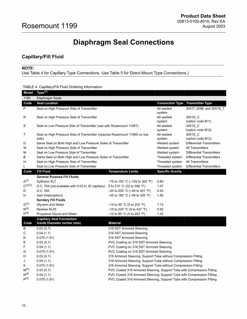
Diaphragm Seal Connections
Capillary/Fill Fluid
NOTE: Use Table 4 for Capillary Type Connections. Use Table 5 for Direct Mount Type Connections.)
TABLE 4. Capillary/Fill Fluid Ordering InformationModel Type(1)
1199 Diaphragm SealsCode Seal Location Connection Type Transmitter TypeP Seal on High Pressure Side of Transmitter All welded
system3051T, 2088, and 3051S_T
R Seal on High Pressure Side of Transmitter All welded system
3051S_C (option code B11)
S Seal on Low Pressure Side of Transmitter (use with Rosemount 1199T) All welded system
3051S_C (option code B12)
T Seal on High Pressure Side of Transmitter (requires Rosemount 1199S on low side)
All welded system
3051S_C (option code B12)
D Same Seal on Both High and Low Pressure Sides of Transmitter Welded system Differential TransmittersW Seal on High Pressure Side of Transmitter Welded system All TransmittersM Seal on Low Pressure Side of Transmitter Welded system Differential TransmittersB Same Seal on Both High and Low Pressure Sides of Transmitter Threaded system Differential TransmittersH Seal on High Pressure Side of Transmitter Threaded system All TransmittersL Seal on Low Pressure Side of Transmitter Threaded system Differential TransmittersCode Fill Fluid Temperature Limits Specific Gravity
General Purpose Fill FluidsA(2) Syltherm XLT �75 to 150 °C (�102 to 302 °F) 0.85C(2)(3) D.C. 704 (not available with 0.03 in. ID capillary) 0 to 315 °C (32 to 599 °F) 1.07D D.C. 200 �45 to 205 °C (�49 to 401 °F) 0.93H Inert (Halocarbon) �45 to 160 °C (�49 to 320 °F) 1.85
Sanitary Fill FluidsG(4) Glycerin and Water �15 to 95 °C (5 to 203 °F) 1.13N(4) Neobee M-20 �15 to 225 °C (5 to 437 °F) 0.92P(4) Propylene Glycol and Water �15 to 95 °C (5 to 203 °F) 1.02
CodeCapillary Seal Connection Inside Diameter inches (mm) Material
B 0.03 (0.7) 316 SST Armored SleevingC 0.04 (1.1) 316 SST Armored SleevingD 0.075 (1.91) 316 SST Armored SleevingE 0.03 (0.7) PVC Coating on 316 SST Armored SleevingF 0.04 (1.1) PVC Coating on 316 SST Armored SleevingG 0.075 (1.91) PVC Coating on 316 SST Armored SleevingH 0.03 (0.7) 316 Armored Sleeving, Support Tube without Compression FittingJ 0.04 (1.1) 316 Armored Sleeving, Support Tube without Compression FittingK 0.075 (1.91) 316 Armored Sleeving, Support Tube without Compression FittingM(5) 0.03 (0.7) PVC Coated 316 Armored Sleeving, Support Tube with Compression FittingN(5) 0.04 (1.1) PVC Coated 316 Armored Sleeving, Support Tube with Compression FittingP(5) 0.075 (1.91) PVC Coated 316 Armored Sleeving, Support Tube with Compression Fitting

Product Data Sheet00813-0100-4016, Rev EAAugust 2003
11
Rosemount 1199
Code Capillary Connection Length01 1 ft (0.3 m)05 5 ft (1.5 m)10 10 ft (3.0 m)15 15 ft (4.5 m)20 20 ft (6.1 m)25 25 ft (7.6 m)30 30 ft (9.1 m)35 35 ft (10.7 m)40 40 ft (12.2 m)45 45 ft (13.7 m)50 50 ft (15.2 m)51 0.5 m (1.6 ft)52 1.0 m (3.3 ft)53 1.5 m (4.9 ft)54 2.0 m (6.6 ft)55 2.5 m (8.2 ft)56 3.0 m (9.8 ft)57 3.5 m (11.5 ft)58 4.0 m (13.1 ft)59 5.0 m (16.4 ft)60 6.0 m (19.7 ft)61 7.0 m (23 ft)62 8.0 m (26.2 ft)63 9.0 m (29.5 ft)64 10.0 m (32.8 ft)65 11.0 m (36.1 ft)66 12.0 m (39.4 ft)67 13.0 m (42.6 ft)68 14.0 m (45.9 ft)69 15.0 m (49.2 ft)
(1) See page 75 for more information on all welded systems and welded connection types.
(2) Available with Welded Seal Location codes D, W, M, P, R, S, or T. Contact factory for use with threaded connections.
(3) Not available with Capillary Seal connection codes B, E, H, or M.
(4) This is a food grade fill fluid.
(5) Compression fitting does not provide a hermetic seal.
TABLE 4. Capillary/Fill Fluid Ordering Information
Product Data Sheet00813-0100-4016, Rev EA
August 2003Rosemount 1199
12
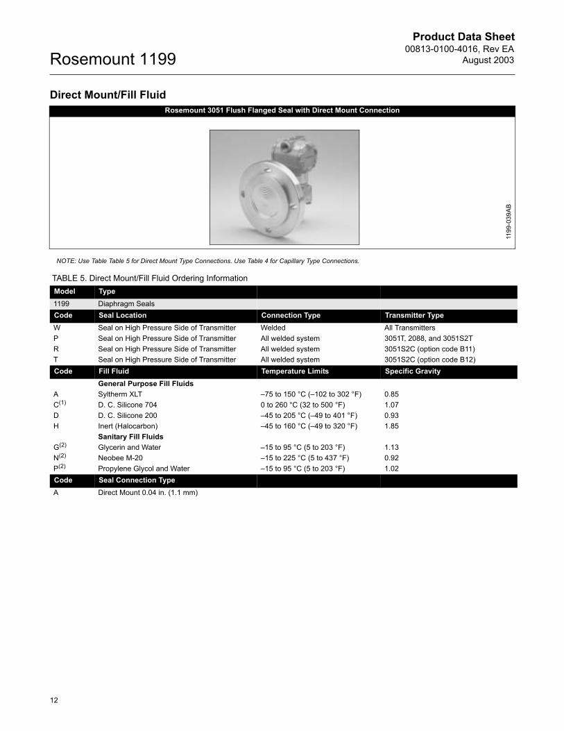
Direct Mount/Fill Fluid
NOTE: Use Table Table 5 for Direct Mount Type Connections. Use Table 4 for Capillary Type Connections.
Rosemount 3051 Flush Flanged Seal with Direct Mount Connection
1199
-039
AB
TABLE 5. Direct Mount/Fill Fluid Ordering InformationModel Type1199 Diaphragm SealsCode Seal Location Connection Type Transmitter TypeW Seal on High Pressure Side of Transmitter Welded All TransmittersP Seal on High Pressure Side of Transmitter All welded system 3051T, 2088, and 3051S2TR Seal on High Pressure Side of Transmitter All welded system 3051S2C (option code B11)T Seal on High Pressure Side of Transmitter All welded system 3051S2C (option code B12)Code Fill Fluid Temperature Limits Specific Gravity
General Purpose Fill FluidsA Syltherm XLT �75 to 150 °C (�102 to 302 °F) 0.85C(1) D. C. Silicone 704 0 to 260 °C (32 to 500 °F) 1.07 D D. C. Silicone 200 �45 to 205 °C (�49 to 401 °F) 0.93H Inert (Halocarbon) �45 to 160 °C (�49 to 320 °F) 1.85
Sanitary Fill FluidsG(2) Glycerin and Water �15 to 95 °C (5 to 203 °F) 1.13N(2) Neobee M-20 �15 to 225 °C (5 to 437 °F) 0.92P(2) Propylene Glycol and Water �15 to 95 °C (5 to 203 °F) 1.02Code Seal Connection Type A Direct Mount 0.04 in. (1.1 mm)
Product Data Sheet00813-0100-4016, Rev EAAugust 2003
13
Rosemount 1199
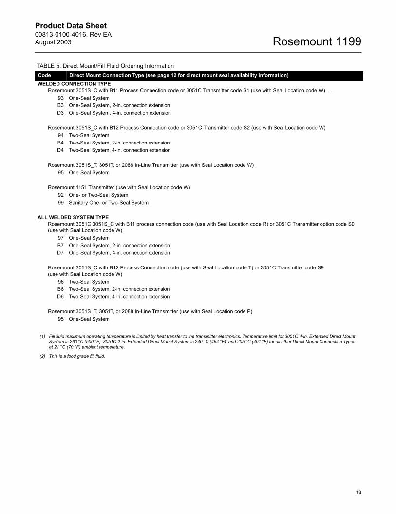
Code Direct Mount Connection Type (see page 12 for direct mount seal availability information)WELDED CONNECTION TYPE
Rosemount 3051S_C with B11 Process Connection code or 3051C Transmitter code S1 (use with Seal Location code W) .93 One-Seal SystemB3 One-Seal System, 2-in. connection extensionD3 One-Seal System, 4-in. connection extension
Rosemount 3051S_C with B12 Process Connection code or 3051C Transmitter code S2 (use with Seal Location code W) 94 Two-Seal SystemB4 Two-Seal System, 2-in. connection extensionD4 Two-Seal System, 4-in. connection extension
Rosemount 3051S_T, 3051T, or 2088 In-Line Transmitter (use with Seal Location code W)95 One-Seal System
Rosemount 1151 Transmitter (use with Seal Location code W)92 One- or Two-Seal System99 Sanitary One- or Two-Seal System
ALL WELDED SYSTEM TYPERosemount 3051C 3051S_C with B11 process connection code (use with Seal Location code R) or 3051C Transmitter option code S0 (use with Seal Location code W)
97 One-Seal SystemB7 One-Seal System, 2-in. connection extensionD7 One-Seal System, 4-in. connection extension
Rosemount 3051S_C with B12 Process Connection code (use with Seal Location code T) or 3051C Transmitter code S9 (use with Seal Location code W)
96 Two-Seal SystemB6 Two-Seal System, 2-in. connection extensionD6 Two-Seal System, 4-in. connection extension
Rosemount 3051S_T, 3051T, or 2088 In-Line Transmitter (use with Seal Location code P)95 One-Seal System
(1) Fill fluid maximum operating temperature is limited by heat transfer to the transmitter electronics. Temperature limit for 3051C 4-in. Extended Direct Mount System is 260 °C (500 °F), 3051C 2-in. Extended Direct Mount System is 240 °C (464 °F), and 205 °C (401 °F) for all other Direct Mount Connection Types at 21 °C (70 °F) ambient temperature.
(2) This is a food grade fill fluid.
TABLE 5. Direct Mount/Fill Fluid Ordering Information
Product Data Sheet00813-0100-4016, Rev EA
August 2003Rosemount 1199
14
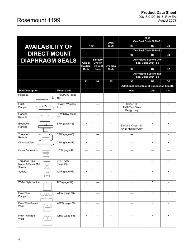
AVAILABILITY OF DIRECT MOUNT
DIAPHRAGM SEALS
11512088/3051T
3051One Seal Code 3051�S1
93 B3 D3
Two Seal Code 3051�S2
94 B4 D4
One or Two Seal
Code
SanitaryOne or
Two Seal Code
One Seal Code
All Welded System OneSeal Code 3051�S0
97 B7 D7
All Welded System Two Seal Code 3051�S9
92 99 95 96 B6 D6
Additional Direct Mount Connection Length
Seal Description Model Code 0 in. 2 in. 4 in.Pancake PFW/PCW (page
16)� � � � � �
Flush Flanged
FFW/FCW (page 21)
� � � Class 150ANSI Two Piece
Design only
� �
Flanged Remote
RFW/RCW (page 37)
� � � � � �
Extended Flanged
EFW (page 42) � � �DIN and Class 150ANSI Flanges Only
� �
Threaded Remote
RTW (page 45) � � � � � �
Chemical Tee CTW (page 47) � � � � � �
Union Connection UCW (page 48) � � � � � �
Threaded Pipe Mount & Paper Mill Sleeve
UCP PMW (page 49)
� � � � � �
Saddle WSP (page 51) � � � � � �
Wafer Style In-Line TFS (page 52) � � � � � �
Flow-Thru Flanged
WFW (page 53) � � � � � �
Flow-Thru Socket Weld
WWW (page 55) � � � � � �
Flow-Thru Butt Weld
WBW (page 55) � � � � � �
Product Data Sheet00813-0100-4016, Rev EAAugust 2003
15
Rosemount 1199
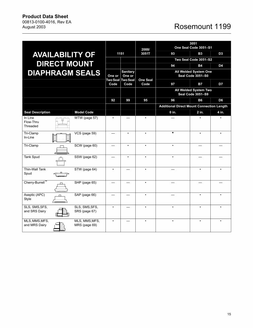
In Line Flow-Thru Threaded
WTW (page 57) � � � � � �
Tri-Clamp In-Line
VCS (page 59) � � � � � �
Tri-Clamp SCW (page 60) � � � � � �
Tank Spud SSW (page 62) � � � � � �
Thin-Wall Tank Spud
STW (page 64) � � � � � �
Cherry-Burrell� SHP (page 65) � � � � � �
Aseptic (APC) Style
SAP (page 66) � � � � � �
SLS, SMS,SFS, and SRS Dairy
SLS, SMS,SFS, SRS (page 67)
� � � � � �
MLS, MMS,MFS, and MRS Dairy
MLS, MMS,MFS, MRS (page 69)
� � � � � �
AVAILABILITY OF DIRECT MOUNT
DIAPHRAGM SEALS
11512088/3051T
3051One Seal Code 3051�S1
93 B3 D3
Two Seal Code 3051�S2
94 B4 D4
One or Two Seal
Code
SanitaryOne or
Two Seal Code
One Seal Code
All Welded System OneSeal Code 3051�S0
97 B7 D7
All Welded System Two Seal Code 3051�S9
92 99 95 96 B6 D6
Additional Direct Mount Connection Length
Seal Description Model Code 0 in. 2 in. 4 in.
Product Data Sheet00813-0100-4016, Rev EA
August 2003Rosemount 1199
16
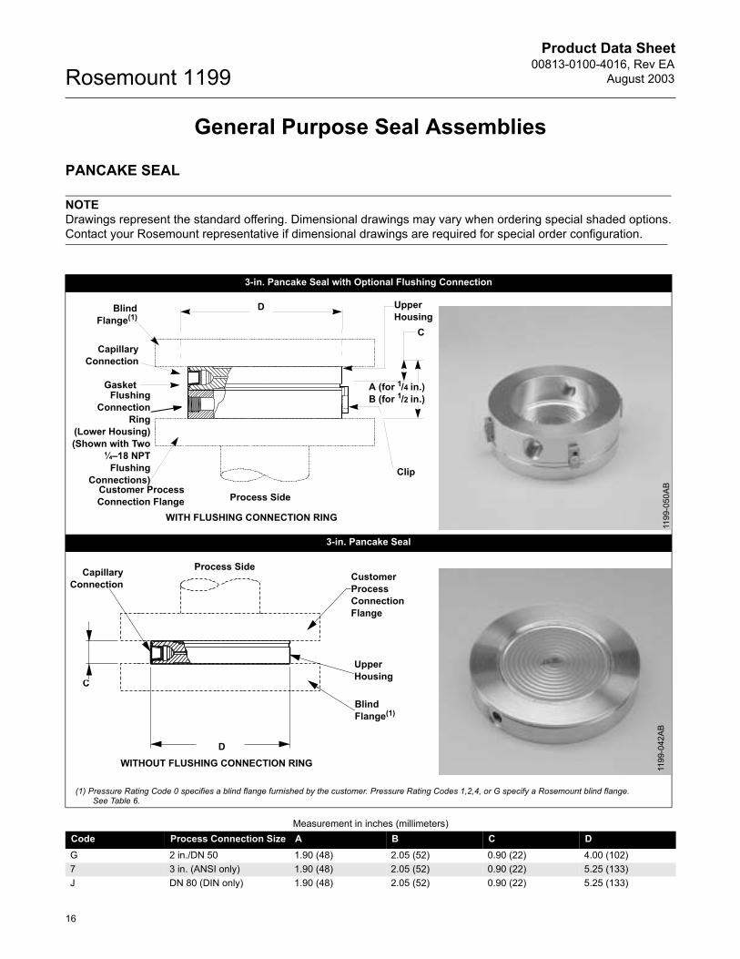
General Purpose Seal Assemblies
PANCAKE SEAL
NOTEDrawings represent the standard offering. Dimensional drawings may vary when ordering special shaded options. Contact your Rosemount representative if dimensional drawings are required for special order configuration.
3-in. Pancake Seal with Optional Flushing Connection
3-in. Pancake Seal
(1) Pressure Rating Code 0 specifies a blind flange furnished by the customer. Pressure Rating Codes 1,2,4, or G specify a Rosemount blind flange. See Table 6.
Measurement in inches (millimeters)Code Process Connection Size A B C DG 2 in./DN 50 1.90 (48) 2.05 (52) 0.90 (22) 4.00 (102)7 3 in. (ANSI only) 1.90 (48) 2.05 (52) 0.90 (22) 5.25 (133)J DN 80 (DIN only) 1.90 (48) 2.05 (52) 0.90 (22) 5.25 (133)
Clip
C
BlindFlange(1)
CapillaryConnection
Customer ProcessConnection Flange
FlushingConnection
Ring(Lower Housing)(Shown with Two
¼�18 NPTFlushing
Connections)
Process Side
A (for 1/4 in.)B (for 1/2 in.)
UpperHousing
D
Gasket
WITH FLUSHING CONNECTION RING
1199
-050
AB
CapillaryConnection
C
D
Customer ProcessConnection Flange
UpperHousing
Blind Flange(1)
Process Side
WITHOUT FLUSHING CONNECTION RING 1199
-042
AB
Product Data Sheet00813-0100-4016, Rev EAAugust 2003
17
Rosemount 1199
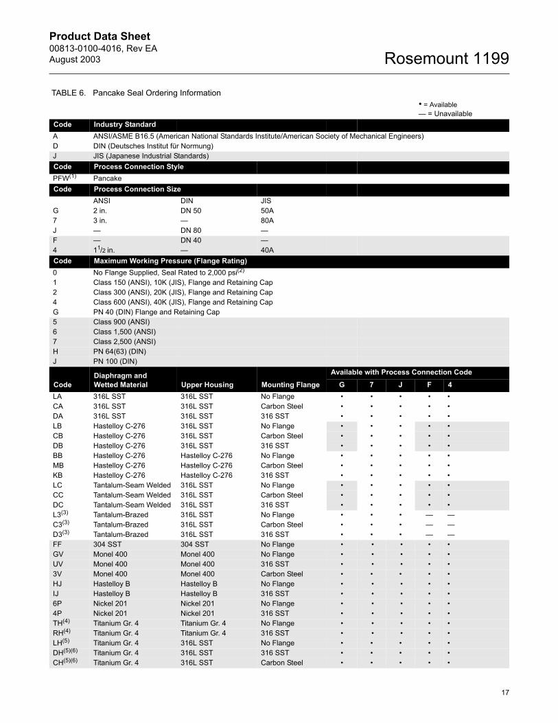
TABLE 6. Pancake Seal Ordering Information � = Available � = Unavailable
Code Industry StandardA ANSI/ASME B16.5 (American National Standards Institute/American Society of Mechanical Engineers)D DIN (Deutsches Institut für Normung)J JIS (Japanese Industrial Standards)Code Process Connection StylePFW(1) PancakeCode Process Connection Size
ANSI DIN JISG 2 in. DN 50 50A7 3 in. � 80AJ � DN 80 �F � DN 40 �4 11/2 in. � 40ACode Maximum Working Pressure (Flange Rating)0 No Flange Supplied, Seal Rated to 2,000 psi(2)
1 Class 150 (ANSI), 10K (JIS), Flange and Retaining Cap 2 Class 300 (ANSI), 20K (JIS), Flange and Retaining Cap4 Class 600 (ANSI), 40K (JIS), Flange and Retaining CapG PN 40 (DIN) Flange and Retaining Cap5 Class 900 (ANSI) 6 Class 1,500 (ANSI) 7 Class 2,500 (ANSI)H PN 64(63) (DIN) J PN 100 (DIN)
CodeDiaphragm and Wetted Material Upper Housing Mounting Flange
Available with Process Connection CodeG 7 J F 4
LA 316L SST 316L SST No Flange � � � � �CA 316L SST 316L SST Carbon Steel � � � � �DA 316L SST 316L SST 316 SST � � � � �LB Hastelloy C-276 316L SST No Flange � � � � �CB Hastelloy C-276 316L SST Carbon Steel � � � � �DB Hastelloy C-276 316L SST 316 SST � � � � �BB Hastelloy C-276 Hastelloy C-276 No Flange � � � � �MB Hastelloy C-276 Hastelloy C-276 Carbon Steel � � � � �KB Hastelloy C-276 Hastelloy C-276 316 SST � � � � �LC Tantalum-Seam Welded 316L SST No Flange � � � � �CC Tantalum-Seam Welded 316L SST Carbon Steel � � � � �DC Tantalum-Seam Welded 316L SST 316 SST � � � � �L3(3) Tantalum-Brazed 316L SST No Flange � � � � �C3(3) Tantalum-Brazed 316L SST Carbon Steel � � � � �D3(3) Tantalum-Brazed 316L SST 316 SST � � � � �FF 304 SST 304 SST No Flange � � � � �GV Monel 400 Monel 400 No Flange � � � � �UV Monel 400 Monel 400 316 SST � � � � �3V Monel 400 Monel 400 Carbon Steel � � � � �HJ Hastelloy B Hastelloy B No Flange � � � � �IJ Hastelloy B Hastelloy B 316 SST � � � � �6P Nickel 201 Nickel 201 No Flange � � � � �4P Nickel 201 Nickel 201 316 SST � � � � �TH(4) Titanium Gr. 4 Titanium Gr. 4 No Flange � � � � �RH(4) Titanium Gr. 4 Titanium Gr. 4 316 SST � � � � �LH(5) Titanium Gr. 4 316L SST No Flange � � � � �DH(5)(6) Titanium Gr. 4 316L SST 316 SST � � � � �CH(5)(6) Titanium Gr. 4 316L SST Carbon Steel � � � � �
Product Data Sheet00813-0100-4016, Rev EA
August 2003Rosemount 1199
18
Code Flushing Connection Ring Material (Lower Housing)(7) 0 No Flushing Connection RingA 316 SSTB Hastelloy C-276D Carbon SteelF 304 L SSTH Titanium Gr. 4J Hastelloy B6 Nickel 201V Monel 400Code Flushing Option0 No Flushing Connection Ring1 One 1/4-in. Flushing Connection3 Two 1/4-in. Flushing Connections7 One 1/2-in. Flushing Connection9 Two 1/2-in. Flushing ConnectionsCode Options B(8) Extra Fill for Cold Temperature Applications C(9) 0.006-in. Diaphragm Thickness (316L SST and Hastelloy C-276 diaphragms only, for abrasive applications)D Hastelloy Plug in Flushing ConnectionG SST Plug in Flushing ConnectionH SST Drain/Vent in Flushing Connection (Not NACE MR01-75 compliant)J Teflon® (PTFE) Gasket (for use with flushing connection ring)K Barium Sulfate-Filled Teflon (PTFE) Gasket (for use with flushing connection ring)V(10) Teflon (PTFE) Coated Diaphragm for nonstick purposes (316L SST and Hastelloy C-276 diaphragms only)4 0.002 Diaphragm Thickness (316L SST and Hastelloy C-276 diaphragms only)T NACE MR-01-75N Grafoil� Gasket (for use with flushing connection ring)U Gold Plated Diaphragm
(1) Shaded areas indicate special orders. Consult your Rosemount representative for configuration availability, performance effects, and lead time.
(2) For pressure greater than 2000 psi flange must be supplied.
(3) For use with customer supplied spiral wound metallic gaskets
(4) Not available with welded capillary connections.
(5) Available with welded capillary connections.
(6) Operating temperature limited to 150 °C (302 °F).
(7) Supplied standard with Thermo-Tork® 9000 gasket.
(8) For seal assemblies that will be used in cold ambient temperature applications, contact your Rosemount representative or reference SOAP 2000 for assistance.
(9) May cause adverse seal temperature effects. Consult your Rosemount representative for assistance.
(10) Not available with transmitter option code Q8, for Material Traceability per DIN EN10204 3.1.B of the transmitter/diaphragm seal assembly.
TABLE 6. (continued) Pancake Seal Ordering Information � = Available � = Unavailable
Product Data Sheet00813-0100-4016, Rev EAAugust 2003
19
Rosemount 1199
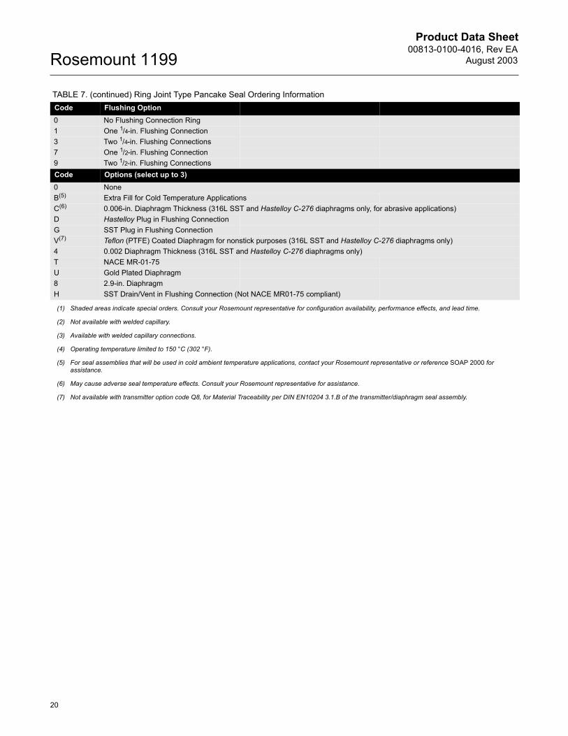
TABLE 7. Ring Joint Type Pancake Seal Ordering InformationCode Industry StandardA ANSI/ASME B16.5 (American National Standards Institute/American Society of Mechanical Engineers)Code Process Connection StylePCW(1) Ring Joint Type PancakeCode Process Connection Size4 11/2 in.G 2 in. 7 3 in. Code Maximum Working Pressure (Flange Rating)1 Class 1502 Class 300 4 Class 600 5 Class 9006 Class 15007 Class 2500Code Diaphragm Material Upper Housing Mounting FlangeLA 316 SST 316 SST No FlangeCA 316 SST 316 SST Carbon SteelDA 316 SST 316 SST 316 SSTBB Hastelloy C-276 Hastelloy C-276 No FlangeMB Hastelloy C-276 Hastelloy C-276 Carbon SteelKB Hastelloy C-276 Hastelloy C-276 316 SSTFF 304 SST 304 SST No FlangeGV Monel 400 Monel 400 No FlangeUV Monel 400 Monel 400 316 SSTHJ Hastelloy B Hastelloy B No FlangeIJ Hastelloy B Hastelloy B 316 SST6P Nickel 201 Nickel 201 No Flange4P Nickel 201 Nickel 201 316 SSTTH(2) Titanium Gr. 4 Titanium Gr. 4 No FlangeRH(2) Titanium Gr. 4 Titanium Gr. 4 316 SSTLH(3)(4) Titanium 316L SST No FlangeDH(3)(4) Titanium 316L SST 316 SSTCH(3)(4) Titanium 316L SST Carbon SteelCode Flushing Connection Ring Material (Lower Housing)0 No Flushing Connection RingA 316 SSTB Hastelloy C-276D Carbon SteelF 304 SSTH Titanium Gr. 4J Hastelloy B6 Nickel 201V Monel 400
Product Data Sheet00813-0100-4016, Rev EA
August 2003Rosemount 1199
20
Code Flushing Option0 No Flushing Connection Ring1 One 1/4-in. Flushing Connection3 Two 1/4-in. Flushing Connections7 One 1/2-in. Flushing Connection9 Two 1/2-in. Flushing ConnectionsCode Options (select up to 3)0 NoneB(5) Extra Fill for Cold Temperature Applications C(6) 0.006-in. Diaphragm Thickness (316L SST and Hastelloy C-276 diaphragms only, for abrasive applications)D Hastelloy Plug in Flushing ConnectionG SST Plug in Flushing ConnectionV(7) Teflon (PTFE) Coated Diaphragm for nonstick purposes (316L SST and Hastelloy C-276 diaphragms only)4 0.002 Diaphragm Thickness (316L SST and Hastelloy C-276 diaphragms only)T NACE MR-01-75U Gold Plated Diaphragm8 2.9-in. Diaphragm H SST Drain/Vent in Flushing Connection (Not NACE MR01-75 compliant)
(1) Shaded areas indicate special orders. Consult your Rosemount representative for configuration availability, performance effects, and lead time.
(2) Not available with welded capillary.
(3) Available with welded capillary connections.
(4) Operating temperature limited to 150 °C (302 °F).
(5) For seal assemblies that will be used in cold ambient temperature applications, contact your Rosemount representative or reference SOAP 2000 for assistance.
(6) May cause adverse seal temperature effects. Consult your Rosemount representative for assistance.
(7) Not available with transmitter option code Q8, for Material Traceability per DIN EN10204 3.1.B of the transmitter/diaphragm seal assembly.
TABLE 7. (continued) Ring Joint Type Pancake Seal Ordering Information

Product Data Sheet00813-0100-4016, Rev EAAugust 2003
21
Rosemount 1199
FFW FLUSH FLANGED REMOTE SEAL
Two-Piece Design (shown with flushing ring)
Mounting Flange
GasketFlushing PortFlushing Ring
Diaphragm
Upper Housing
Instrument Connection
KF
2.10 / 2.29 (53 / 58)
A
C
L
B
G
D
Flushing Ring Clamp0.31 / 0.50 (8 / 13)
TABLE 8. Dimensional Table for Flush Flanged Raised Face Diaphragm Seals Two Piece (Upper Housing and Flange) DesignMeasurement in inches (millimeters)
Pipe Size Class
Flange Diameter�A�
Flange Thickness�B�
Bolt Circle�C� Bolts
Bolt Hole Diameter�D�
Standard Diaphragm Diameter�F�
Raised Face Diameter�G�
AN
SI /
ASM
E / J
IS
11/2 -in. 150 lb. 5.00 (127) 0.63 (16) 3.88 (99) 4 0.62 (16) 1.90 (48) 2.88 (73)300 lb. 6.12 (156) 0.75 (19) 4.50 (114) 4 0.88 (22) 1.90 (48) 2.88 (73)600 lb. 6.12 (156) 0.88 (22) 4.50 (114) 4 0.88 (22) 1.90 (48) 2.88 (73)
2-in. 150 lb. 6.00 (152) 0.69 (18) 4.75 (121) 4 0.75 (19) 2.30 (58) 3.62 (92)300 lb. 6.50 (165) 0.82 (21) 5.00 (127) 8 0.75 (19) 2.30 (58) 3.62 (92)600 lb. 6.50 (165) 1.00 (25) 5.00 (127) 8 0.75 (19) 2.30 (58) 3.62 (92)
3-in. 150 lb. 7.50 (191) 0.88 (22) 6.00 (152) 4 0.75 (19) 3.50 (89) 5.00 (127)300 lb. 8.25 (210) 1.07 (27) 6.62 (168) 8 0.88 (22) 3.50 (89) 5.00 (127)600 lb. 8.25 (210) 1.25 (32) 6.62 (168) 8 0.88 (22) 3.50 (89) 5.00 (127)
4-in. 150 lb. 9.00 (229) 0.88 (22) 7.50 (191) 8 0.75 (19) 3.50 (89) 6.20 (157)300 lb. 10.0 (254) 1.19 (30) 7.88 (200) 8 0.88 (22) 3.50 (89) 6.20 (157)600 lb. 10.75 (273) 1.50 (38) 8.50 (216) 8 1.00 (25) 3.50 (89) 6.20 (157)
DN 50 PN 40 6.50 (165) 0.79 (20) 4.92 (125) 4 0.71 (18) 2.30 (58) 4.00 (102)
DIN
PN 64 7.08 (180) 1.02 (26) 5.31 (135) 4 0.87 (22) 2.30 (58) 4.00 (102)PN 100 7.68 (195) 1.10 (28) 5.71 (145) 4 1.02 (26) 2.30 (58) 4.00 (102)
DN 80 PN 40 7.87 (200) 0.94 (24) 6.30 (160) 8 0.71 (18) 3.50 (89) 5.43 (138)PN 64 8.46 (215) 1.10 (28) 6.69 (170) 8 0.88 (22) 3.50 (89) 5.43 (138)PN 100 9.06 (230) 1.26 (32) 7.09 (180) 8 1.02 (26) 3.50 (89) 5.43 (138)
DN 100 PN 16 8.66 (220) 0.79 (20) 7.09 (180) 8 0.71 (18) 3.50 (89) 6.20 (157)PN 40 9.25 (235) 0.94 (24) 7.48 (190) 8 0.87 (22) 3.50 (89) 6.20 (157)PN 64 9.84 (250) 1.18 (30) 7.87 (200) 8 1.02 (26) 3.50 (89) 6.20 (157)
Product Data Sheet00813-0100-4016, Rev EA
August 2003Rosemount 1199
22
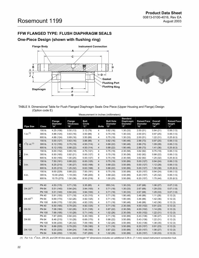
FFW FLANGED TYPE: FLUSH DIAPHRAGM SEALSOne-Piece Design (shown with flushing ring)
Instrument ConnectionFlange Body
GasketFlushing PortFlushing Ring
Diaphragm K
G
L
H
A
C
D
B
J
F
TABLE 9. Dimensional Table for Flush Flanged Diaphragm Seals One Piece (Upper Housing and Flange) Design (Option code E)
Measurement in inches (millimeters)
Pipe Size Class
Flange Diameter�A�
Flange Thickness�B�
Bolt Circle�C� Bolts
Bolt Hole Diameter�D�
Standard Diaphragm Diameter�F�
Raised Face Diameter�G�
Overall Height �H�
Raised Face Height�J�
AN
SI /
ASM
E / J
IS
1-in.(1)150 lb. 4.25 (108) 0.50 (13) 3.12 (79) 4 0.62 (16) 1.30 (33) 2.00 (51) 0.84 (21) 0.06 (1.5)300 lb. 4.88 (124) 0.63 (16) 3.50 (89) 4 0.75 (19) 1.30 (33) 2.00 (51) 0.97 (25) 0.06 (1.5)600 lb. 4.88 (124) 0.69 (16) 3.50 (89) 4 0.75 (19) 1.30 (33) 2.00 (51) 1.22 (31) 0.25 (6.3)
11/2 -in.(1)150 lb. 5.00 (127) 0.63 (16) 3.88 (99) 4 0.62 (16) 1.90 (48) 2.88 (73) 0.97 (25) 0.06 (1.5)300 lb. 6.12 (155) 0.75 (19) 4.50 (114) 4 0.88 (22) 1.90 (48) 2.88 (73) 1.09 (28) 0.06 (1.5)600 lb. 6.12 (155) 0.88 (22) 4.50 (114) 4 0.88 (22) 1.90 (48) 2.88 (73) 1.41 (36) 0.25 (6.3)
2-in.150 lb. 6.00 (152) 0.69 (18) 4.75 (121) 4 0.75 (19) 2.30 (58) 3.62 (92) 0.75 (19) 0.06 (1.5)300 lb. 6.50 (165) 0.82 (21) 5.00 (127) 8 0.75 (19) 2.30 (58) 3.62 (92) 0.88 (22) 0.06 (1.5)600 lb. 6.50 (165) 1.00 (25) 5.00 (127) 8 0.75 (19) 2.30 (58) 3.62 (92) 1.25 (32) 0.25 (6.3)
3-in.150 lb. 7.50 (191) 0.88 (22) 6.00 (125) 4 0.75 (19) 3.50 (89) 5.00 (127) 0.94 (24) 0.06 (1.5)300 lb. 8.25 (210) 1.06 (27) 6.62 (168) 8 0.88 (22) 3.50 (89) 5.00 (127) 1.12 (28) 0.06 (1.5)600 lb. 8.25 (210) 1.25 (32) 6.62 (168) 8 0.88 (22) 3.50 (89) 5.00 (127) 1.50 (38) 0.25 (6.3)
4-in.150 lb. 9.00 (229) 0.88 (22) 7.50 (191) 8 0.75 (19) 3.50 (89) 6.20 (157) 0.94 (24) 0.06 (1.5)300 lb. 10.00 (254) 1.19 (30) 7.88 (200) 8 0.88 (22) 3.50 (89) 6.20 (157) 1.25 (32) 0.06 (1.5)600 lb. 10.75 (273) 1.50 (38) 8.50 (216) 8 1.00 (25) 3.50 (89) 6.20 (157) 1.75 (44) 0.25 (6.3)
DIN
DN 25(1)PN 40 4.53 (115) 0.71 (18) 3.35 (85) 4 055 (14) 1.30 (33) 2.67 (68) 1.06 (27) 0.07 (1.8)PN 64 5.51 (140) 0.94 (24) 3.94 (100) 4 0.71 (18) 1.30 (33) 2.67 (68) 1.29 (33) 0.07 (1.8)PN 100 5.51 (140) 0.94 (24) 3.94 (100) 4 0.71 (18) 1.30 (33) 2.67 (68) 1.29 (33) 0.07 (1.8)
DN 40(1)PN 40 5.91 (150) 0.71 (18) 4.33 (110) 4 0.71 (18) 1.90 (48) 3.46 (88) 1.11 (28) 0.12 (3)PN 64 6.69 (170) 1.02 (26) 4.92 (125) 4 0.71 (18) 1.90 (48) 3.46 (88) 1.42 (36) 0.12 (3)PN 100 6.69 (170) 1.02 (26) 4.92 (125) 4 0.71 (18) 1.90 (48) 3.46 (88) 1.42 (36) 0.12 (3)
DN 50PN 40 6.50 (165) 0.79 (20) 4.92 (125) 4 0.71 (18) 2.30 (58) 4.00 (102) 0.91 (23) 0.12 (3)PN 64 7.08 (180) 1.02 (26) 5.31 (135) 4 0.87 (22) 2.30 (58) 4.00 (102) 1.14 (29) 0.12 (3)PN 100 7.68 (195) 1.10 (28) 5.71 (145) 4 1.02 (26) 2.30 (58) 4.00 (102) 1.22 (31) 0.12 (3)
DN 80PN 40 7.87 (200) 0.94 (24) 6.30 (160) 8 0.71 (18) 3.50 (89) 5.43 (138) 1.06 (27) 0.12 (3)PN 64 8.46 (215) 1.10 (28) 6.69 (170) 8 0.88 (22) 3.50 (89) 5.43 (138) 1.22 (31) 0.12 (3)PN 100 9.06 (230) 1.26 (32) 7.09 (180) 8 1.02 (26) 3.50 (89) 5.43 (138) 1.38 (35) 0.12 (3)
DN 100PN 16 8.66 (220) 0.79 (20) 7.09 (180) 8 0.71 (18) 3.50 (89) 6.20 (157) 0.91 (23) 0.12 (3)PN 40 9.25 (235) 0.94 (24) 7.48 (190) 8 0.87 (22) 3.50 (89) 6.20 (157) 1.06 (27) 0.12 (3)PN 64 9.84 (250) 1.18 (30) 7.87 (200) 8 1.02 (26) 3.50 (89) 6.20 (157) 1.30 (33) 0.12 (3)
(1) For 1-in. 11/2-in., DN 25, and DN 40 line sizes, overall height �H� dimensions includes an additional 0.28-in. (7.1 mm) raised instrument connection hub.
Product Data Sheet00813-0100-4016, Rev EAAugust 2003
23
Rosemount 1199
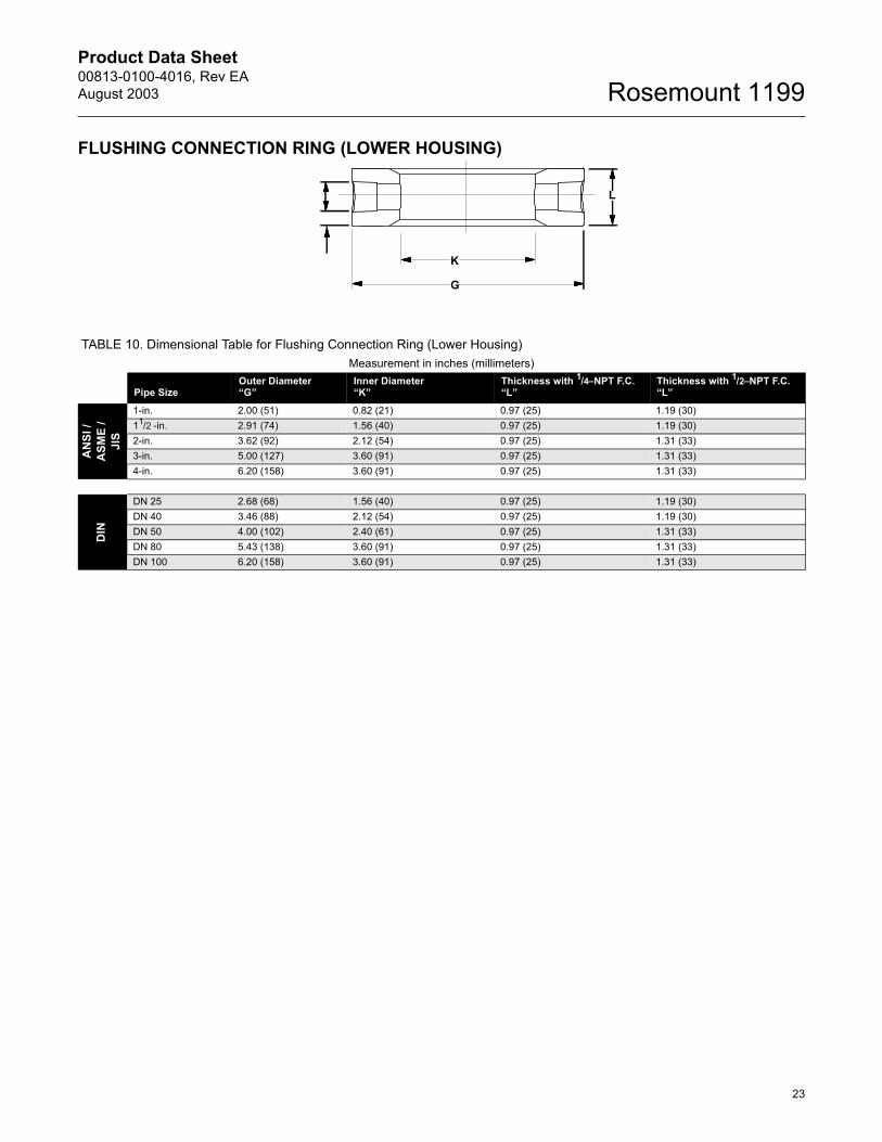
FLUSHING CONNECTION RING (LOWER HOUSING)
L
K
G
TABLE 10. Dimensional Table for Flushing Connection Ring (Lower Housing)Measurement in inches (millimeters)
Pipe SizeOuter Diameter�G�
Inner Diameter�K�
Thickness with 1/4�NPT F.C.�L�
Thickness with 1/2�NPT F.C.�L�
AN
SI /
ASM
E /
JIS
1-in. 2.00 (51) 0.82 (21) 0.97 (25) 1.19 (30)11/2 -in. 2.91 (74) 1.56 (40) 0.97 (25) 1.19 (30)2-in. 3.62 (92) 2.12 (54) 0.97 (25) 1.31 (33)3-in. 5.00 (127) 3.60 (91) 0.97 (25) 1.31 (33)4-in. 6.20 (158) 3.60 (91) 0.97 (25) 1.31 (33)
DIN
DN 25 2.68 (68) 1.56 (40) 0.97 (25) 1.19 (30)DN 40 3.46 (88) 2.12 (54) 0.97 (25) 1.19 (30)DN 50 4.00 (102) 2.40 (61) 0.97 (25) 1.31 (33)DN 80 5.43 (138) 3.60 (91) 0.97 (25) 1.31 (33)DN 100 6.20 (158) 3.60 (91) 0.97 (25) 1.31 (33)
Product Data Sheet00813-0100-4016, Rev EA
August 2003Rosemount 1199
24
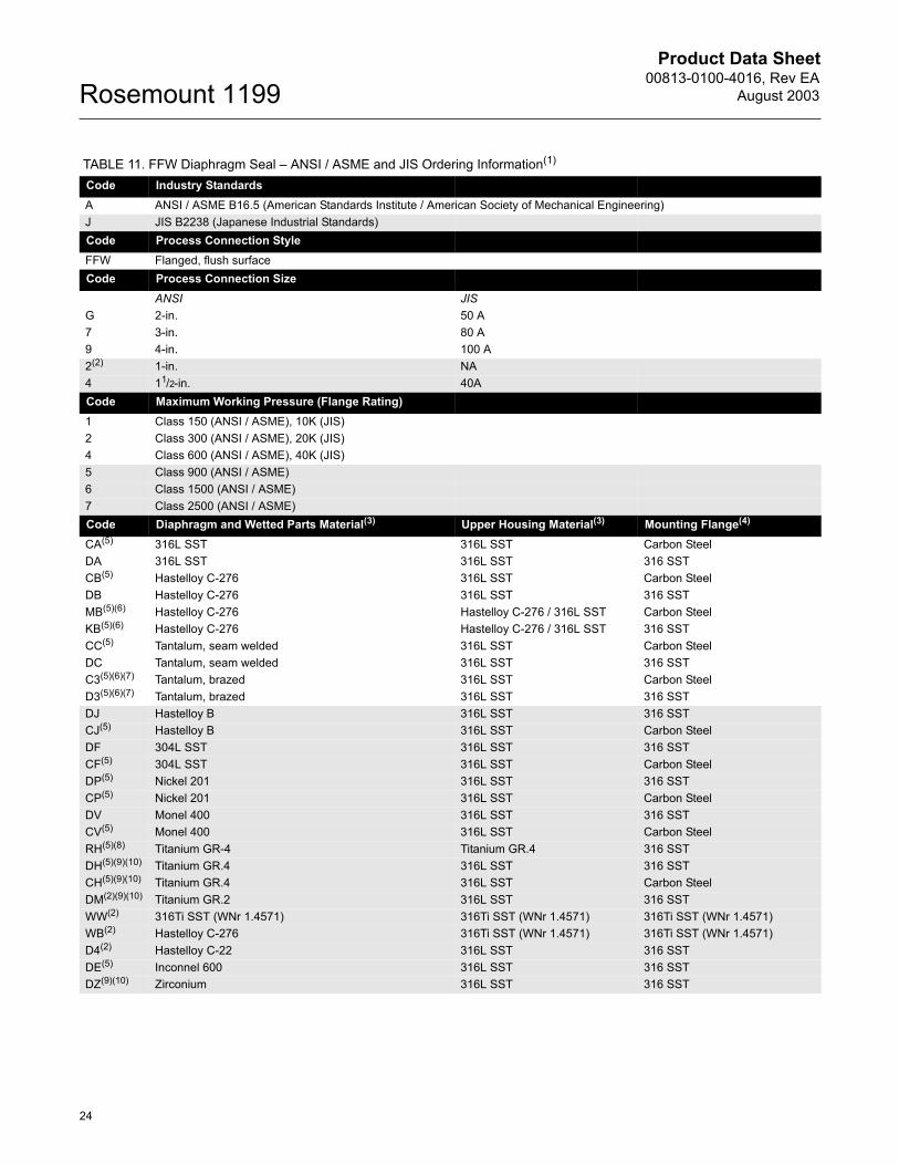
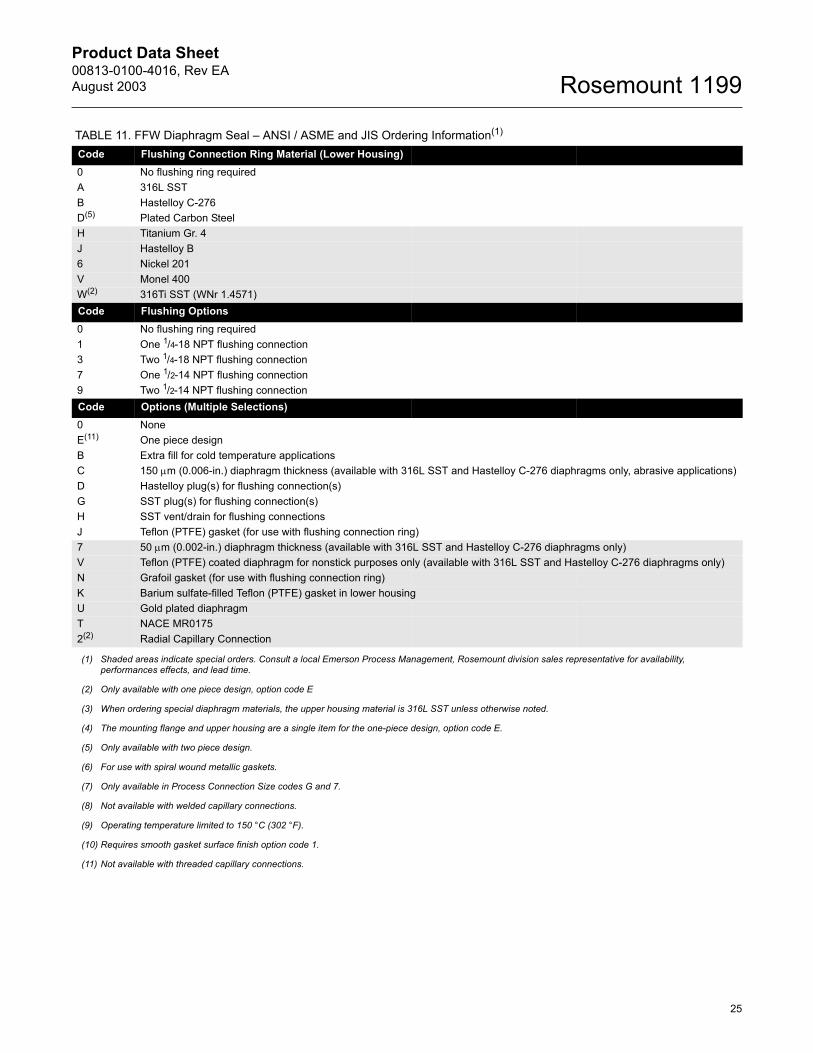
TABLE 11. FFW Diaphragm Seal � ANSI / ASME and JIS Ordering Information(1)
Code Industry StandardsA ANSI / ASME B16.5 (American Standards Institute / American Society of Mechanical Engineering)J JIS B2238 (Japanese Industrial Standards)Code Process Connection StyleFFW Flanged, flush surfaceCode Process Connection Size
ANSI JISG 2-in. 50 A7 3-in. 80 A9 4-in. 100 A2(2) 1-in. NA4 11/2-in. 40ACode Maximum Working Pressure (Flange Rating)1 Class 150 (ANSI / ASME), 10K (JIS)2 Class 300 (ANSI / ASME), 20K (JIS)4 Class 600 (ANSI / ASME), 40K (JIS)5 Class 900 (ANSI / ASME)6 Class 1500 (ANSI / ASME)7 Class 2500 (ANSI / ASME)Code Diaphragm and Wetted Parts Material(3) Upper Housing Material(3) Mounting Flange(4)
CA(5) 316L SST 316L SST Carbon Steel DA 316L SST 316L SST 316 SSTCB(5) Hastelloy C-276 316L SST Carbon SteelDB Hastelloy C-276 316L SST 316 SSTMB(5)(6) Hastelloy C-276 Hastelloy C-276 / 316L SST Carbon SteelKB(5)(6) Hastelloy C-276 Hastelloy C-276 / 316L SST 316 SSTCC(5) Tantalum, seam welded 316L SST Carbon SteelDC Tantalum, seam welded 316L SST 316 SSTC3(5)(6)(7) Tantalum, brazed 316L SST Carbon SteelD3(5)(6)(7) Tantalum, brazed 316L SST 316 SSTDJ Hastelloy B 316L SST 316 SSTCJ(5) Hastelloy B 316L SST Carbon SteelDF 304L SST 316L SST 316 SSTCF(5) 304L SST 316L SST Carbon SteelDP(5) Nickel 201 316L SST 316 SSTCP(5) Nickel 201 316L SST Carbon SteelDV Monel 400 316L SST 316 SSTCV(5) Monel 400 316L SST Carbon SteelRH(5)(8) Titanium GR-4 Titanium GR.4 316 SSTDH(5)(9)(10) Titanium GR.4 316L SST 316 SSTCH(5)(9)(10) Titanium GR.4 316L SST Carbon SteelDM(2)(9)(10) Titanium GR.2 316L SST 316 SSTWW(2) 316Ti SST (WNr 1.4571) 316Ti SST (WNr 1.4571) 316Ti SST (WNr 1.4571)WB(2) Hastelloy C-276 316Ti SST (WNr 1.4571) 316Ti SST (WNr 1.4571)D4(2) Hastelloy C-22 316L SST 316 SSTDE(5) Inconnel 600 316L SST 316 SSTDZ(9)(10) Zirconium 316L SST 316 SST
Product Data Sheet00813-0100-4016, Rev EAAugust 2003
25
Rosemount 1199
Code Flushing Connection Ring Material (Lower Housing)0 No flushing ring requiredA 316L SSTB Hastelloy C-276D(5) Plated Carbon SteelH Titanium Gr. 4J Hastelloy B6 Nickel 201V Monel 400W(2) 316Ti SST (WNr 1.4571)Code Flushing Options0 No flushing ring required1 One 1/4-18 NPT flushing connection3 Two 1/4-18 NPT flushing connection7 One 1/2-14 NPT flushing connection9 Two 1/2-14 NPT flushing connectionCode Options (Multiple Selections)0 NoneE(11) One piece designB Extra fill for cold temperature applicationsC 150 µm (0.006-in.) diaphragm thickness (available with 316L SST and Hastelloy C-276 diaphragms only, abrasive applications)D Hastelloy plug(s) for flushing connection(s)G SST plug(s) for flushing connection(s)H SST vent/drain for flushing connectionsJ Teflon (PTFE) gasket (for use with flushing connection ring)7 50 µm (0.002-in.) diaphragm thickness (available with 316L SST and Hastelloy C-276 diaphragms only)V Teflon (PTFE) coated diaphragm for nonstick purposes only (available with 316L SST and Hastelloy C-276 diaphragms only)N Grafoil gasket (for use with flushing connection ring)K Barium sulfate-filled Teflon (PTFE) gasket in lower housingU Gold plated diaphragm T NACE MR01752(2) Radial Capillary Connection
(1) Shaded areas indicate special orders. Consult a local Emerson Process Management, Rosemount division sales representative for availability, performances effects, and lead time.
(2) Only available with one piece design, option code E
(3) When ordering special diaphragm materials, the upper housing material is 316L SST unless otherwise noted.
(4) The mounting flange and upper housing are a single item for the one-piece design, option code E.
(5) Only available with two piece design.
(6) For use with spiral wound metallic gaskets.
(7) Only available in Process Connection Size codes G and 7.
(8) Not available with welded capillary connections.
(9) Operating temperature limited to 150 °C (302 °F).
(10) Requires smooth gasket surface finish option code 1.
(11) Not available with threaded capillary connections.
TABLE 11. FFW Diaphragm Seal � ANSI / ASME and JIS Ordering Information(1)
Product Data Sheet00813-0100-4016, Rev EA
August 2003Rosemount 1199
26
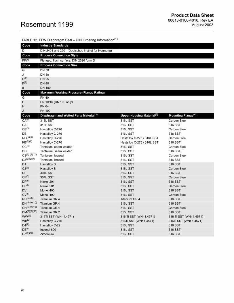
TABLE 12. FFW Diaphragm Seal � DIN Ordering Information(1)
Code Industry StandardsD DIN 2401 and 2501 (Deutsches Institut fur Normung)Code Process Connection StyleFFW Flanged, flush surface, DIN 2526 form DCode Process Connection SizeG DN 50J DN 80D(2) DN 25F(2) DN 409 DN 100Code Maximum Working Pressure (Flange Rating)G PN 40E PN 10/16 (DN 100 only)H PN 64J PN 100Code Diaphragm and Wetted Parts Material(3) Upper Housing Material(3) Mounting Flange(4)
CA(5) 316L SST 316L SST Carbon Steel DA 316L SST 316L SST 316 SSTCB(5) Hastelloy C-276 316L SST Carbon SteelDB Hastelloy C-276 316L SST 316 SSTMB(5)(6) Hastelloy C-276 Hastelloy C-276 / 316L SST Carbon SteelKB(5)(6) Hastelloy C-276 Hastelloy C-276 / 316L SST 316 SSTCC(5) Tantalum, seam welded 316L SST Carbon SteelDC Tantalum, seam welded 316L SST 316 SSTC3(5) (6) (7) Tantalum, brazed 316L SST Carbon SteelD3(5)(6)(7) Tantalum, brazed 316L SST 316 SSTDJ Hastelloy B 316L SST 316 SSTCJ(5) Hastelloy B 316L SST Carbon SteelDF 304L SST 316L SST 316 SSTCF(5) 304L SST 316L SST Carbon SteelDP(5) Nickel 201 316L SST 316 SSTCP(5) Nickel 201 316L SST Carbon SteelDV Monel 400 316L SST 316 SSTCV(5) Monel 400 316L SST Carbon SteelRH(5) (8) Titanium GR.4 Titanium GR.4 316 SSTDH(5)(9)(10) Titanium GR.4 316L SST 316 SSTCH(5)(9)(10) Titanium GR.4 316L SST Carbon SteelDM(2)(9)(10) Titanium GR.2 316L SST 316 SSTWW(2) 316Ti SST (WNr 1.4571) 316 Ti SST (WNr 1.4571) 316 Ti SST (WNr 1.4571)WB(2) Hastelloy C-276 316Ti SST (WNr 1.4571) 316Ti SST (WNr 1.4571)D4(2) Hastelloy C-22 316L SST 316 SSTDE(5) Inconel 600 316L SST 316 SSTDZ(9)(10) Zirconium 316L SST 316 SST
Product Data Sheet00813-0100-4016, Rev EAAugust 2003
27
Rosemount 1199
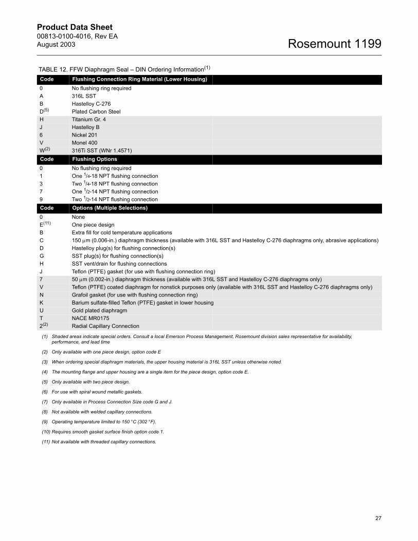
Code Flushing Connection Ring Material (Lower Housing)0 No flushing ring requiredA 316L SSTB Hastelloy C-276D(5) Plated Carbon SteelH Titanium Gr. 4J Hastelloy B6 Nickel 201V Monel 400W(2) 316Ti SST (WNr 1.4571)Code Flushing Options0 No flushing ring required1 One 1/4-18 NPT flushing connection3 Two 1/4-18 NPT flushing connection7 One 1/2-14 NPT flushing connection9 Two 1/2-14 NPT flushing connectionCode Options (Multiple Selections)0 NoneE(11) One piece designB Extra fill for cold temperature applicationsC 150 µm (0.006-in.) diaphragm thickness (available with 316L SST and Hastelloy C-276 diaphragms only, abrasive applications)D Hastelloy plug(s) for flushing connection(s)G SST plug(s) for flushing connection(s)H SST vent/drain for flushing connectionsJ Teflon (PTFE) gasket (for use with flushing connection ring)7 50 µm (0.002-in.) diaphragm thickness (available with 316L SST and Hastelloy C-276 diaphragms only)V Teflon (PTFE) coated diaphragm for nonstick purposes only (available with 316L SST and Hastelloy C-276 diaphragms only)N Grafoil gasket (for use with flushing connection ring)K Barium sulfate-filled Teflon (PTFE) gasket in lower housingU Gold plated diaphragm T NACE MR01752(2) Radial Capillary Connection
(1) Shaded areas indicate special orders. Consult a local Emerson Process Management, Rosemount division sales representative for availability, performance, and lead time
(2) Only available with one piece design, option code E
(3) When ordering special diaphragm materials, the upper housing material is 316L SST unless otherwise noted.
(4) The mounting flange and upper housing are a single item for the piece design, option code E.
(5) Only available with two piece design.
(6) For use with spiral wound metallic gaskets.
(7) Only available in Process Connection Size code G and J.
(8) Not available with welded capillary connections.
(9) Operating temperature limited to 150 °C (302 °F).
(10) Requires smooth gasket surface finish option code 1.
(11) Not available with threaded capillary connections.
TABLE 12. FFW Diaphragm Seal � DIN Ordering Information(1)
Product Data Sheet00813-0100-4016, Rev EA
August 2003Rosemount 1199
28
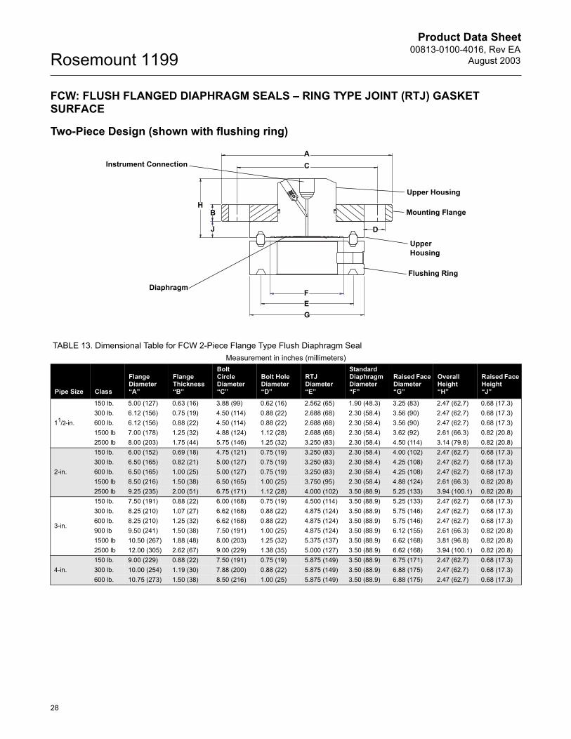
FCW: FLUSH FLANGED DIAPHRAGM SEALS � RING TYPE JOINT (RTJ) GASKET SURFACE
Two-Piece Design (shown with flushing ring)
Instrument Connection
Upper Housing
Diaphragm
Flushing Ring
B
J
AC
D
H
FEG
Upper Housing
Mounting Flange
TABLE 13. Dimensional Table for FCW 2-Piece Flange Type Flush Diaphragm SealMeasurement in inches (millimeters)
Pipe Size Class
Flange Diameter�A�
Flange Thickness�B�
Bolt Circle Diameter�C�
Bolt Hole Diameter�D�
RTJ Diameter�E�
Standard Diaphragm Diameter�F�
Raised Face Diameter�G�
Overall Height �H�
Raised Face Height�J�
11/2-in.
150 lb. 5.00 (127) 0.63 (16) 3.88 (99) 0.62 (16) 2.562 (65) 1.90 (48.3) 3.25 (83) 2.47 (62.7) 0.68 (17.3)300 lb. 6.12 (156) 0.75 (19) 4.50 (114) 0.88 (22) 2.688 (68) 2.30 (58.4) 3.56 (90) 2.47 (62.7) 0.68 (17.3)600 lb. 6.12 (156) 0.88 (22) 4.50 (114) 0.88 (22) 2.688 (68) 2.30 (58.4) 3.56 (90) 2.47 (62.7) 0.68 (17.3)1500 lb 7.00 (178) 1.25 (32) 4.88 (124) 1.12 (28) 2.688 (68) 2.30 (58.4) 3.62 (92) 2.61 (66.3) 0.82 (20.8)2500 lb 8.00 (203) 1.75 (44) 5.75 (146) 1.25 (32) 3.250 (83) 2.30 (58.4) 4.50 (114) 3.14 (79.8) 0.82 (20.8)
2-in.
150 lb. 6.00 (152) 0.69 (18) 4.75 (121) 0.75 (19) 3.250 (83) 2.30 (58.4) 4.00 (102) 2.47 (62.7) 0.68 (17.3)300 lb. 6.50 (165) 0.82 (21) 5.00 (127) 0.75 (19) 3.250 (83) 2.30 (58.4) 4.25 (108) 2.47 (62.7) 0.68 (17.3)600 lb. 6.50 (165) 1.00 (25) 5.00 (127) 0.75 (19) 3.250 (83) 2.30 (58.4) 4.25 (108) 2.47 (62.7) 0.68 (17.3)1500 lb 8.50 (216) 1.50 (38) 6.50 (165) 1.00 (25) 3.750 (95) 2.30 (58.4) 4.88 (124) 2.61 (66.3) 0.82 (20.8)2500 lb 9.25 (235) 2.00 (51) 6.75 (171) 1.12 (28) 4.000 (102) 3.50 (88.9) 5.25 (133) 3.94 (100.1) 0.82 (20.8)
3-in.
150 lb. 7.50 (191) 0.88 (22) 6.00 (168) 0.75 (19) 4.500 (114) 3.50 (88.9) 5.25 (133) 2.47 (62.7) 0.68 (17.3)300 lb. 8.25 (210) 1.07 (27) 6.62 (168) 0.88 (22) 4.875 (124) 3.50 (88.9) 5.75 (146) 2.47 (62.7) 0.68 (17.3)600 lb. 8.25 (210) 1.25 (32) 6.62 (168) 0.88 (22) 4.875 (124) 3.50 (88.9) 5.75 (146) 2.47 (62.7) 0.68 (17.3)900 lb 9.50 (241) 1.50 (38) 7.50 (191) 1.00 (25) 4.875 (124) 3.50 (88.9) 6.12 (155) 2.61 (66.3) 0.82 (20.8)1500 lb 10.50 (267) 1.88 (48) 8.00 (203) 1.25 (32) 5.375 (137) 3.50 (88.9) 6.62 (168) 3.81 (96.8) 0.82 (20.8)2500 lb 12.00 (305) 2.62 (67) 9.00 (229) 1.38 (35) 5.000 (127) 3.50 (88.9) 6.62 (168) 3.94 (100.1) 0.82 (20.8)
4-in. 150 lb. 9.00 (229) 0.88 (22) 7.50 (191) 0.75 (19) 5.875 (149) 3.50 (88.9) 6.75 (171) 2.47 (62.7) 0.68 (17.3)300 lb. 10.00 (254) 1.19 (30) 7.88 (200) 0.88 (22) 5.875 (149) 3.50 (88.9) 6.88 (175) 2.47 (62.7) 0.68 (17.3)600 lb. 10.75 (273) 1.50 (38) 8.50 (216) 1.00 (25) 5.875 (149) 3.50 (88.9) 6.88 (175) 2.47 (62.7) 0.68 (17.3)

Product Data Sheet00813-0100-4016, Rev EAAugust 2003
29
Rosemount 1199
One-Piece Design
Diaphragm
Instrument Connection
A
F
E
G
D
C
B
H
Mounting Flange / Upper Housing
TABLE 14. Dimensional Table for FCW 1-Piece Flange Type Flush Diaphragm SealMeasurement in inches (millimeters)
Pipe Size Class
Flange Diameter�A�
Overall Height�B�
Bolt Circle Diameter�C�
Bolt Hole Diameter�D�
RTJ Diameter�E�
Standard Diaphragm Diameter�F�
Raised Face Diameter�G�
Raised Face Height�H�
11/2-in.
300 lb. 6.12 (156) 0.88 (22.4) 4.50 (114) 0.88 (22) 2.688 (68) 2.30 (58.4) 3.56 (90) 0.25 (6.4)600 lb. 6.12 (156) 0.88 (22.4) 4.50 (114) 0.88 (22) 2.688 (68) 2.30 (58.4) 3.56 (90) 0.25 (6.4)1500 lb 7.00 (178) 1.25 (31.8) 4.88 (124) 1.12 (28) 2.688 (68) 2.30 (58.4) 3.62 (92) 0.25 (6.4)2500 lb 8.00 (203) 1.75 (44.5) 5.75 (146) 1.25 (32) 3.250 (83) 2.30 (58.4) 4.50 (114) 0.312 (7.92)
2-in.
150 lb. 6.00 (152) 0.94 (23.9) 4.75 (121) 0.75 (19) 3.250 (83) 2.30 (58.4) 4.00 (102) 0.25 (6.4)300 lb. 6.50 (165) 1.13 (28.7) 5.00 (127) 0.75 (19) 3.250 (83) 2.30 (58.4) 4.25 (108) 0.312 (7.92)600 lb. 6.50 (165) 1.31 (33.3) 5.00 (127) 0.75 (19) 3.250 (83) 2.30 (58.4) 4.25 (108) 0.312 (7.92)1500 lb 8.50 (216) 1.81 (46.0) 6.50 (165) 1.00 (25) 3.750 (95) 2.30 (58.4) 4.88 (124) 0.312 (7.92)2500 lb 9.25 (235) 2.31 (58.7) 6.75 (171) 1.12 (28) 4.000 (102) 3.50 (88.9) 5.25 (133) 0.312 (7.92)
3-in.
150 lb. 7.50 (191) 1.13 (28.7) 6.00 (168) 0.75 (19) 4.500 (114) 3.50 (88.9) 5.25 (133) 0.25 (6.4)300 lb. 8.25 (210) 1.37 (34.8) 6.62 (168) 0.88 (22) 4.875 (124) 3.50 (88.9) 5.75 (146) 0.312 (7.92)600 lb. 8.25 (210) 1.56 (39.6) 6.62 (138) 0.88 (22) 4.875 (124) 3.50 (88.9) 5.75 (146) 0.312 (7.92)900 lb 9.50 (241) 1.81 (46.0) 7.50 (191) 1.00 (25) 4.875 (124) 3.50 (88.9) 6.12 (155) 0.312 (7.92)1500 lb 10.50 (267) 2.19 (55.6) 8.00 (203) 1.25 (32) 5.375 (137) 3.50 (88.9) 6.62 (168) 0.312 (7.92)2500 lb 12.00 (305) 3.00 (76.2) 9.00 (229) 1.38 (35) 5.000 (127) 3.50 (88.9) 6.62 (168) 0.375 (9.52)
4-in.150 lb. 9.00 (229) 1.13 (28.7) 7.50 (191) 0.75 (19) 5.875 (149) 3.50 (88.9) 6.75 (171) 0.25 (6.4)300 lb. 10.00 (254) 1.50 (38.1) 7.88 (200) 0.88 (22) 5.875 (149) 3.50 (88.9) 6.88 (175) 0.312 (7.92)600 lb. 10.75 (273) 1.81 (46.0) 8.50 (216) 1.00 (25) 5.875 (149) 3.50 (88.9) 6.88 (175) 0.312 (7.92)
Product Data Sheet00813-0100-4016, Rev EA
August 2003Rosemount 1199
30
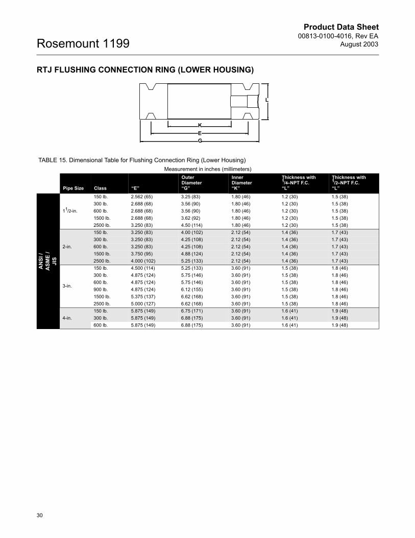
RTJ FLUSHING CONNECTION RING (LOWER HOUSING)
KEG
L
TABLE 15. Dimensional Table for Flushing Connection Ring (Lower Housing)Measurement in inches (millimeters)
Pipe Size Class �E�
Outer Diameter�G�
Inner Diameter�K�
Thickness with 1/4�NPT F.C.�L�
Thickness with1/2�NPT F.C.�L�
AN
SI /
ASM
E /
JIS
11/2-in.
150 lb. 2.562 (65) 3.25 (83) 1.80 (46) 1.2 (30) 1.5 (38)300 lb. 2.688 (68) 3.56 (90) 1.80 (46) 1.2 (30) 1.5 (38)600 lb. 2.688 (68) 3.56 (90) 1.80 (46) 1.2 (30) 1.5 (38)1500 lb. 2.688 (68) 3.62 (92) 1.80 (46) 1.2 (30) 1.5 (38)2500 lb. 3.250 (83) 4.50 (114) 1.80 (46) 1.2 (30) 1.5 (38)
2-in.
150 lb. 3.250 (83) 4.00 (102) 2.12 (54) 1.4 (36) 1.7 (43)300 lb. 3.250 (83) 4.25 (108) 2.12 (54) 1.4 (36) 1.7 (43)600 lb. 3.250 (83) 4.25 (108) 2.12 (54) 1.4 (36) 1.7 (43)1500 lb. 3.750 (95) 4.88 (124) 2.12 (54) 1.4 (36) 1.7 (43)2500 lb. 4.000 (102) 5.25 (133) 2.12 (54) 1.4 (36) 1.7 (43)
3-in.
150 lb. 4.500 (114) 5.25 (133) 3.60 (91) 1.5 (38) 1.8 (46)300 lb. 4.875 (124) 5.75 (146) 3.60 (91) 1.5 (38) 1.8 (46)600 lb. 4.875 (124) 5.75 (146) 3.60 (91) 1.5 (38) 1.8 (46)900 lb. 4.875 (124) 6.12 (155) 3.60 (91) 1.5 (38) 1.8 (46)1500 lb. 5.375 (137) 6.62 (168) 3.60 (91) 1.5 (38) 1.8 (46)2500 lb. 5.000 (127) 6.62 (168) 3.60 (91) 1.5 (38) 1.8 (46)
4-in. 150 lb. 5.875 (149) 6.75 (171) 3.60 (91) 1.6 (41) 1.9 (48)300 lb. 5.875 (149) 6.88 (175) 3.60 (91) 1.6 (41) 1.9 (48)600 lb. 5.875 (149) 6.88 (175) 3.60 (91) 1.6 (41) 1.9 (48)
Product Data Sheet00813-0100-4016, Rev EAAugust 2003
31
Rosemount 1199
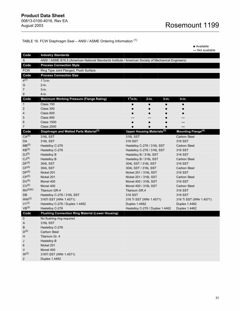
TABLE 16. FCW Diaphragm Seal � ANSI / ASME Ordering Information (1)
● Available� Not available
Code Industry StandardsA ANSI / ASME B16.5 (American National Standards Institute / American Society of Mechanical Engineers)Code Process Connection StyleFCW Ring Type Joint Flanged, Flush SurfaceCode Process Connection Size4(2) 11/2-in. G 2-in. 7 3-in. 9 4-in. Code Maximum Working Pressure (Flange Rating) 11/2-in. 2-in. 3-in. 4-in. 1 Class 150 ● ● ● ●
2 Class 300 ● ● ● ●
4 Class 600 ● ● ● ●
5 Class 900 � � ● �6 Class 1500 ● ● ● �7 Class 2500 ● ● ● �Code Diaphragm and Wetted Parts Material(3) Upper Housing Materials(3) Mounting Flange(4)
CA(5) 316L SST 316L SST Carbon Steel DA 316L SST 316 SST 316 SSTMB(5) Hastelloy C-276 Hastelloy C-276 / 316L SST Carbon SteelKB(5) Hastelloy C-276 Hastelloy C-276 / 316L SST 316 SSTDJ(5) Hastelloy B Hastelloy B / 316L SST 316 SSTCJ(5) Hastelloy B Hastelloy B / 316L SST Carbon SteelDF(5) 304L SST 304L SST / 316L SST 316 SSTCF(5) 304L SST 304L SST / 316L SST Carbon SteelDP(5) Nickel 201 Nickel 201 / 316L SST 316 SSTCP(5) Nickel 201 Nickel 201 / 316L SST Carbon SteelDV(5) Monel 400 Monel 400 / 316L SST 316 SSTCV(5) Monel 400 Monel 400 / 316L SST Carbon SteelRH(5)(6) Titanium GR-4 Titanium GR.4 316 SSTDB Hastelloy C-276 / 316L SST 316 SST 316 SSTWW(2) 316Ti SST (WNr 1.4571) 316 Ti SST (WNr 1.4571) 316 Ti SST (WNr 1.4571)V1(2) Hastelloy C-276 / Duplex 1.4462 Duplex 1.4462 Duplex 1.4462VB(5) Hastelloy C-276 Hastelloy C-276 / Duplex 1.4462 Duplex 1.4462Code Flushing Connection Ring Material (Lower Housing)0 No flushing ring requiredA 316L SSTB Hastelloy C-276D(5) Carbon SteelH Titanium Gr. 4J Hastelloy B6 Nickel 201V Monel 400W(2) 316Ti SST (WNr 1.4571)2 Duplex 1.4462

Product Data Sheet00813-0100-4016, Rev EA
August 2003Rosemount 1199
32
Code Flushing Options0 No flushing ring required1 One 1/4-18 NPT flushing connection3 Two 1/4-18 NPT flushing connection7 One 1/2-14 NPT flushing connection9 Two 1/2-14 NPT flushing connectionCode Options (Multiple Selections)0 NoneE(7) One piece designB Extra fill for cold temperature applicationsC 150 µm (0.006-in.) diaphragm thickness (available with 316L SST and Hastelloy C-276 diaphragms only, abrasive applications)D Hastelloy plug(s) for flushing connection(s)G SST plug(s) for flushing connection(s)H SST vent/drain for flushing connectionsV Teflon (PTFE) coated diaphragm for nonstick purposes only (available with 316L SST and Hastelloy C-276 diaphragms only)7 50 µm (0.002-in.) diaphragm thickness (available with 316L SST and Hastelloy C-276 diaphragms only)U Gold plated diaphragmT NACE MR01752(2) Radial Capillary Connection
(1) Shaded areas indicate special orders. Consult a local Emerson Process Management, Rosemount division sales representative for availability, performance, and lead time
(2) Only available with one piece design, option code E.
(3) When ordering special diaphragm materials, the upper housing material is 316L SST unless otherwise noted.
(4) The mounting flange and upper housing are a single item for the one-piece design, option code E.
(5) Only available with two piece design.
(6) Not available with welded capillary connections.
(7) Not available with threaded capillary connections.
TABLE 16. FCW Diaphragm Seal � ANSI / ASME Ordering Information (1)
● Available� Not available
Product Data Sheet00813-0100-4016, Rev EAAugust 2003
33
Rosemount 1199
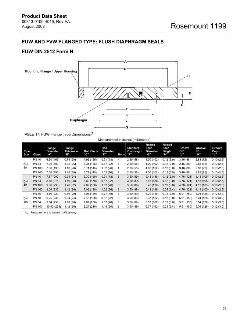
FUW AND FVW FLANGED TYPE: FLUSH DIAPHRAGM SEALS
FUW DIN 2512 Form N
TABLE 17. FUW Flange Type Dimensions(1)
Measurement in inches (millimeters)
Pipe Size Class
Flange Diameter�A�
Flange Thickness �B�
Bolt Circle�C�
Bolt Diameter �D� Bolts
Standard Diaphragm �F�
Raised Face Diameter �G�
Raised Face Height �H�
Groove O.D. �J�
Groove I.D.�K�
Groove Depth�L�
DN 50
PN 40 6.50 (165) 0.79 (20) 4.92 (125) 0.71 (18) 4 2.30 (58) 4.00 (102) 0.12 (3.0) 3.46 (88) 2.83 (72) 0.10 (2.5)PN 64 7.09 (180) 1.02 (26) 5.31 (135) 0.87 (22) 4 2.30 (58) 4.00 (102) 0.12 (3.0) 3.46 (88) 2.83 (72) 0.10 (2.5)PN 100 7.68 (195) 1.10 (28) 5.71 (145) 1.02 (26) 4 2.30 (58) 4.00 (102) 0.12 (3.0) 3.46 (88) 2.83 (72) 0.10 (2.5)PN 160 7.68 (195) 1.18 (30) 5.71 (145) 1.02 (26) 4 2.30 (58) 4.00 (102) 0.12 (3.0) 3.46 (88) 2.83 (72) 0.10 (2.5)
DN 80
PN 40 7.87 (200) 0.94 (24) 6.30 (160) 0.71 (18) 8 3.50 (89) 5.43 (138) 0.12 (3.0) 4.76 (121) 4.13 (105) 0.10 (2.5)PN 64 8.46 (215) 1.10 (28) 6.69 (170) 0.87 (22) 8 3.50 (89) 5.43 (138) 0.12 (3.0) 4.76 (121) 4.13 (105) 0.10 (2.5)PN 100 9.06 (230) 1.26 (32) 7.09 (180) 1.02 (26) 8 3.50 (89) 5.43 (138) 0.12 (3.0) 4.76 (121) 4.13 (105) 0.10 (2.5)PN 160 9.06 (230) 1.42 (36) 7.09 (180) 1.02 (26) 8 3.50 (89) 5.43 (138) 0.25 (6.4) 4.76 (121) 4.13 (105) 0.10 (2.5)
DN 100
PN 16 8.66 (220) 0.79 (20) 7.08 (180) 0.71 (18) 8 3.50 (89) 6.22 (158) 0.12 (3.0) 5.91 (150) 5.04 (128) 0.12 (3.0)PN 40 9.25 (235) 0.94 (24) 7.48 (190) 0.87 (22) 8 3.50 (89) 6.37 (162) 0.12 (3.0) 5.91 (150) 5.04 (128) 0.12 (3.0)PN 64 9.84 (250) 1.18 (30) 7.87 (200) 1.02 (26) 8 3.50 (89) 6.37 (162) 0.12 (3.0) 5.91 (150) 5.04 (128) 0.12 (3.0)PN 100 10.43 (265) 1.42 (36) 8.27 (210) 1.18 (30) 8 3.50 (89) 6.37 (162) 0.25 (6.4) 5.91 (150) 5.04 (128) 0.12 (3.0)
(1) Measurement in inches (millimeters).
Mounting Flange / Upper Housing
Diaphragm
B
H
D
C
A
L
FKJ
G
Product Data Sheet00813-0100-4016, Rev EA
August 2003Rosemount 1199
34
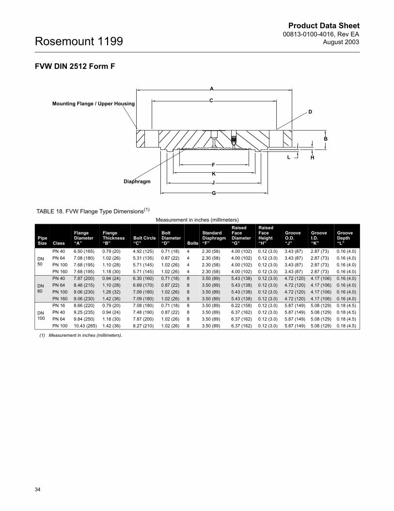
FVW DIN 2512 Form F
Diaphragm
B
H
D
C
A
LFKJ
G
Mounting Flange / Upper Housing
TABLE 18. FVW Flange Type Dimensions(1)
Measurement in inches (millimeters)
Pipe Size Class
Flange Diameter�A�
Flange Thickness�B�
Bolt Circle�C�
Bolt Diameter�D� Bolts
Standard Diaphragm�F�
Raised FaceDiameter�G�
Raised Face Height�H�
Groove O.D.�J�
Groove I.D.�K�
Groove Depth�L�
DN 50
PN 40 6.50 (165) 0.79 (20) 4.92 (125) 0.71 (18) 4 2.30 (58) 4.00 (102) 0.12 (3.0) 3.43 (87) 2.87 (73) 0.16 (4.0)PN 64 7.08 (180) 1.02 (26) 5.31 (135) 0.87 (22) 4 2.30 (58) 4.00 (102) 0.12 (3.0) 3.43 (87) 2.87 (73) 0.16 (4.0)PN 100 7.68 (195) 1.10 (28) 5.71 (145) 1.02 (26) 4 2.30 (58) 4.00 (102) 0.12 (3.0) 3.43 (87) 2.87 (73) 0.16 (4.0)PN 160 7.68 (195) 1.18 (30) 5.71 (145) 1.02 (26) 4 2.30 (58) 4.00 (102) 0.12 (3.0) 3.43 (87) 2.87 (73) 0.16 (4.0)
DN 80
PN 40 7.87 (200) 0.94 (24) 6.30 (160) 0.71 (18) 8 3.50 (89) 5.43 (138) 0.12 (3.0) 4.72 (120) 4.17 (106) 0.16 (4.0)PN 64 8.46 (215) 1.10 (28) 6.69 (170) 0.87 (22) 8 3.50 (89) 5.43 (138) 0.12 (3.0) 4.72 (120) 4.17 (106) 0.16 (4.0)PN 100 9.06 (230) 1.26 (32) 7.09 (180) 1.02 (26) 8 3.50 (89) 5.43 (138) 0.12 (3.0) 4.72 (120) 4.17 (106) 0.16 (4.0)PN 160 9.06 (230) 1.42 (36) 7.09 (180) 1.02 (26) 8 3.50 (89) 5.43 (138) 0.12 (3.0) 4.72 (120) 4.17 (106) 0.16 (4.0)
DN 100
PN 16 8.66 (220) 0.79 (20) 7.08 (180) 0.71 (18) 8 3.50 (89) 6.22 (158) 0.12 (3.0) 5.87 (149) 5.08 (129) 0.18 (4.5)PN 40 9.25 (235) 0.94 (24) 7.48 (190) 0.87 (22) 8 3.50 (89) 6.37 (162) 0.12 (3.0) 5.87 (149) 5.08 (129) 0.18 (4.5)PN 64 9.84 (250) 1.18 (30) 7.87 (200) 1.02 (26) 8 3.50 (89) 6.37 (162) 0.12 (3.0) 5.87 (149) 5.08 (129) 0.18 (4.5)PN 100 10.43 (265) 1.42 (36) 8.27 (210) 1.02 (26) 8 3.50 (89) 6.37 (162) 0.12 (3.0) 5.87 (149) 5.08 (129) 0.18 (4.5)
(1) Measurement in inches (millimeters).
Product Data Sheet00813-0100-4016, Rev EAAugust 2003
35
Rosemount 1199
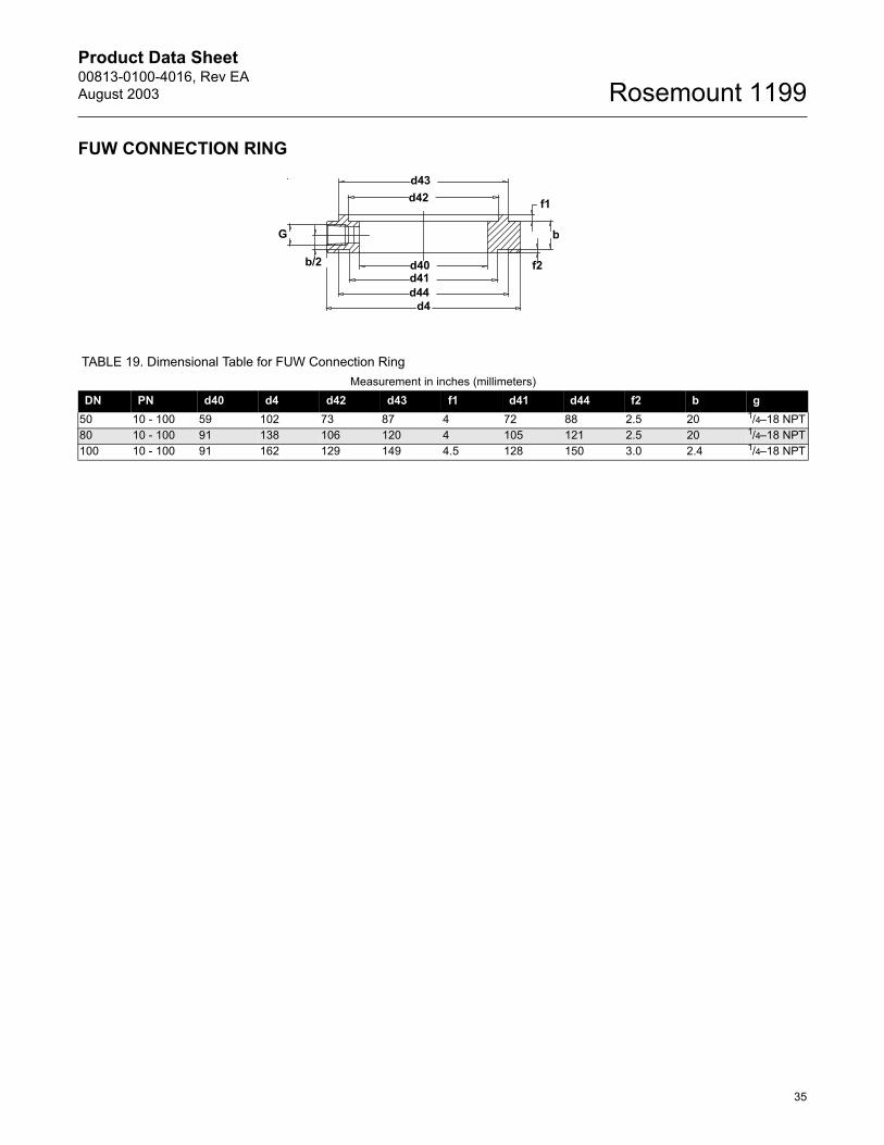
FUW CONNECTION RING
TABLE 19. Dimensional Table for FUW Connection RingMeasurement in inches (millimeters)
DN PN d40 d4 d42 d43 f1 d41 d44 f2 b g50 10 - 100 59 102 73 87 4 72 88 2.5 20 1/4�18 NPT80 10 - 100 91 138 106 120 4 105 121 2.5 20 1/4�18 NPT100 10 - 100 91 162 129 149 4.5 128 150 3.0 2.4 1/4�18 NPT
b
d4
b/2
G
f1
f2
d43d42
d41d40
d44
Product Data Sheet00813-0100-4016, Rev EA
August 2003Rosemount 1199
36
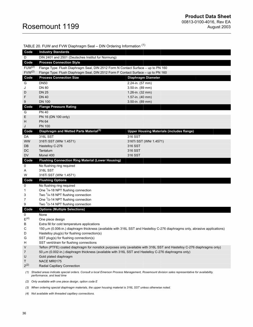
TABLE 20. FUW and FVW Diaphragm Seal � DIN Ordering Information (1)
Code Industry StandardsD DIN 2401 and 2501 (Deutsches Institut fur Normung)Code Process Connection StyleFUW(2) Flange Type: Flush Diaphragm Seal, DIN 2512 Form N Contact Surface � up to PN 160FVW(2) Flange Type: Flush Diaphragm Seal, DIN 2512 Form F Contact Surface � up to PN 160Code Process Connection Size Diaphragm DiameterG DN50 2.24-in. (57 mm)J DN 80 3.50-in. (89 mm)D DN 25 1.26-in. (32 mm)F DN 40 1.57-in. (40 mm)9 DN 100 3.50-in. (89 mm)Code Flange Pressure RatingG PN 40 E PN 16 (DN 100 only)H PN 64 J PN 100Code Diaphragm and Wetted Parts Material(3) Upper Housing Materials (includes flange)DA 316L SST 316 SSTWW 316Ti SST (WNr 1.4571) 316Ti SST (WNr 1.4571)DB Hastelloy C-276 316 SSTDC Tantalum 316 SSTDV Monel 400 316 SSTCode Flushing Connection Ring Material (Lower Housing)0 No flushing ring requiredA 316L SSTW 316Ti SST (WNr 1.4571)Code Flushing Options0 No flushing ring required1 One 1/4-18 NPT flushing connection3 Two 1/4-18 NPT flushing connection7 One 1/2-14 NPT flushing connection9 Two 1/2-14 NPT flushing connectionCode Options (Multiple Selections)0 NoneE(4) One piece designB Extra fill for cold temperature applicationsC 150 µm (0.006-in.) diaphragm thickness (available with 316L SST and Hastelloy C-276 diaphragms only, abrasive applications)D Hastelloy plug(s) for flushing connection(s)G SST plug(s) for flushing connection(s)H SST vent/drain for flushing connectionsV Teflon (PTFE) coated diaphragm for nonstick purposes only (available with 316L SST and Hastelloy C-276 diaphragms only)7 50 µm (0.002-in.) diaphragm thickness (available with 316L SST and Hastelloy C-276 diaphragms only)U Gold plated diaphragmT NACE MR01752(2) Radial Capillary Connection
(1) Shaded areas indicate special orders. Consult a local Emerson Process Management, Rosemount division sales representative for availability, performance, and lead time
(2) Only available with one piece design, option code E
(3) When ordering special diaphragm materials, the upper housing material is 316L SST unless otherwise noted.
(4) Not available with threaded capillary connections.
Product Data Sheet00813-0100-4016, Rev EAAugust 2003
37
Rosemount 1199
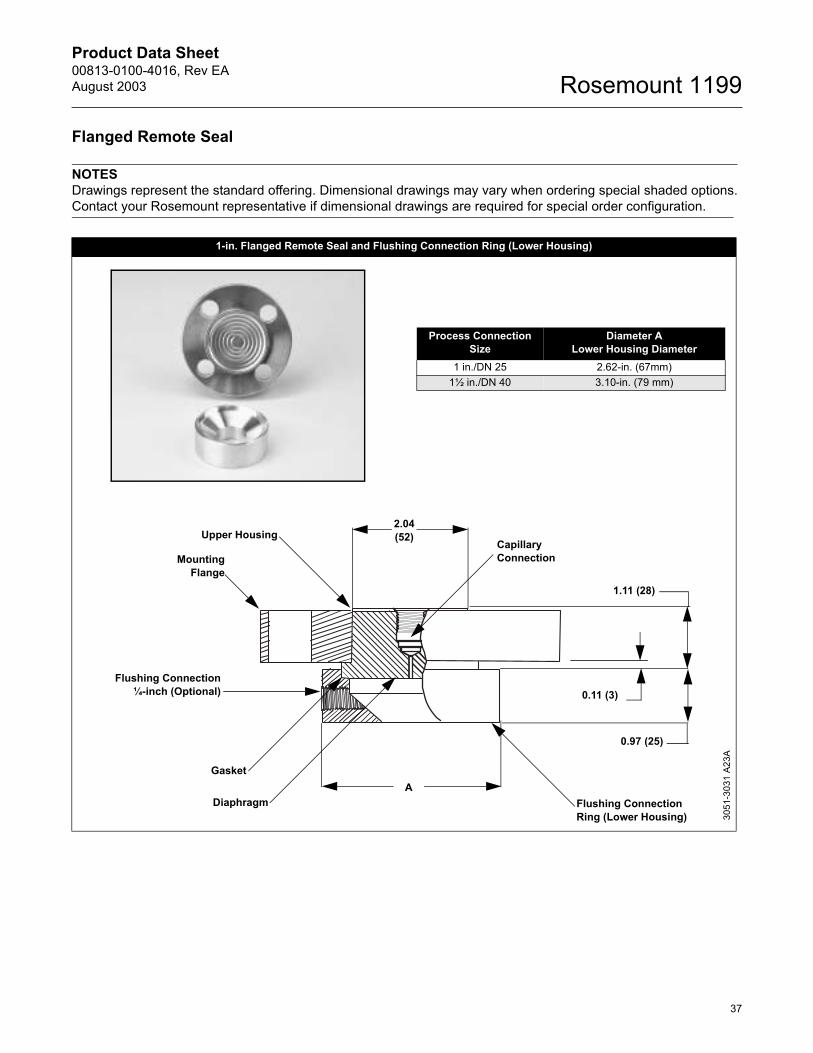
Flanged Remote Seal
NOTESDrawings represent the standard offering. Dimensional drawings may vary when ordering special shaded options. Contact your Rosemount representative if dimensional drawings are required for special order configuration.
1-in. Flanged Remote Seal and Flushing Connection Ring (Lower Housing)
Process Connection Size
Diameter ALower Housing Diameter
1 in./DN 25 2.62-in. (67mm)1½ in./DN 40 3.10-in. (79 mm)
Upper Housing
MountingFlange
CapillaryConnection
0.97 (25)
1.11 (28)
Gasket
Flushing Connection¼-inch (Optional)
Diaphragm Flushing Connection Ring (Lower Housing)
0.11 (3)
A
2.04(52)
3051
-303
1 A2
3A
Product Data Sheet00813-0100-4016, Rev EA
August 2003Rosemount 1199
38
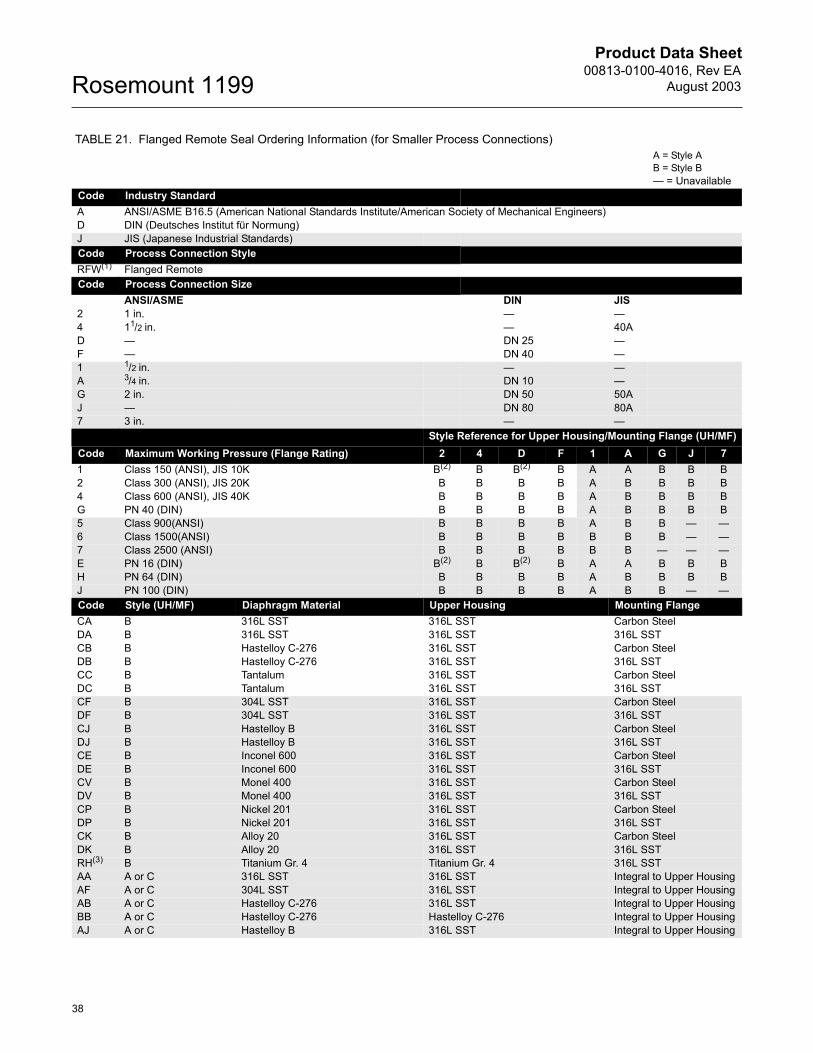
TABLE 21. Flanged Remote Seal Ordering Information (for Smaller Process Connections) A = Style AB = Style B� = Unavailable
Code Industry StandardA ANSI/ASME B16.5 (American National Standards Institute/American Society of Mechanical Engineers)D DIN (Deutsches Institut für Normung)J JIS (Japanese Industrial Standards)Code Process Connection StyleRFW(1) Flanged RemoteCode Process Connection Size
ANSI/ASME DIN JIS2 1 in. � �4 11/2 in. � 40AD � DN 25 �F � DN 40 �1 1/2 in. � �A 3/4 in. DN 10 �G 2 in. DN 50 50AJ � DN 80 80A7 3 in. � �
Style Reference for Upper Housing/Mounting Flange (UH/MF)Code Maximum Working Pressure (Flange Rating) 2 4 D F 1 A G J 71 Class 150 (ANSI), JIS 10K B(2) B B(2) B A A B B B2 Class 300 (ANSI), JIS 20K B B B B A B B B B4 Class 600 (ANSI), JIS 40K B B B B A B B B BG PN 40 (DIN) B B B B A B B B B5 Class 900(ANSI) B B B B A B B � �6 Class 1500(ANSI) B B B B B B B � �7 Class 2500 (ANSI) B B B B B B � � �E PN 16 (DIN) B(2) B B(2) B A A B B BH PN 64 (DIN) B B B B A B B B BJ PN 100 (DIN) B B B B A B B � �Code Style (UH/MF) Diaphragm Material Upper Housing Mounting FlangeCA B 316L SST 316L SST Carbon SteelDA B 316L SST 316L SST 316L SSTCB B Hastelloy C-276 316L SST Carbon SteelDB B Hastelloy C-276 316L SST 316L SSTCC B Tantalum 316L SST Carbon SteelDC B Tantalum 316L SST 316L SSTCF B 304L SST 316L SST Carbon SteelDF B 304L SST 316L SST 316L SSTCJ B Hastelloy B 316L SST Carbon SteelDJ B Hastelloy B 316L SST 316L SSTCE B Inconel 600 316L SST Carbon SteelDE B Inconel 600 316L SST 316L SSTCV B Monel 400 316L SST Carbon SteelDV B Monel 400 316L SST 316L SSTCP B Nickel 201 316L SST Carbon SteelDP B Nickel 201 316L SST 316L SSTCK B Alloy 20 316L SST Carbon SteelDK B Alloy 20 316L SST 316L SSTRH(3) B Titanium Gr. 4 Titanium Gr. 4 316L SSTAA A or C 316L SST 316L SST Integral to Upper HousingAF A or C 304L SST 316L SST Integral to Upper HousingAB A or C Hastelloy C-276 316L SST Integral to Upper HousingBB A or C Hastelloy C-276 Hastelloy C-276 Integral to Upper HousingAJ A or C Hastelloy B 316L SST Integral to Upper Housing

Product Data Sheet00813-0100-4016, Rev EAAugust 2003
39
Rosemount 1199
AE A or C Inconel 600 316L SST Integral to Upper HousingAV A or C Monel 400 316L SST Integral to Upper HousingAP A or C Nickel 201 316L SST Integral to Upper HousingAC A or C Tantalum 316L SST Integral to Upper HousingAK A or C Alloy 20 316L SST Integral to Upper HousingTH(3) A or C Titanium Gr. 4 Titanium Gr. 4 Integral to Upper HousingCH(4) B Titanium Gr. 4 316L SST Carbon SteelDH(4) B Titanium Gr. 4 316L SST 316L SSTAH(4) A or C Titanium Gr. 4 316L SST Integral to Upper HousingCode Flushing Connection Ring Material (Lower Housing)(5) A 316 SSTB Hastelloy C-276D Carbon SteelC 316 SST (tantalum lining, no flushing connection allowed) (Grafoil gasket standard) NA for process connection code 1 and AF 304 SSTH Titanium Gr. 4J Hastelloy B6 Nickel 201V Monel 400E Inconel 6001 Inconel 625K Alloy 20Code Flushing Options1 One ¼-in. Flushing Connection3 Two ¼-in. Flushing Connections5 No Flushing Connection7 One 1/2-in. Flushing Connection 9 Two 1/2-in. Flushing ConnectionsCode OptionsB(6) Extra Fill for Cold Temperature Applications C(7) 0.006-in. Diaphragm Thickness (316L SST and Hastelloy C-276 diaphragms only, for abrasive applications)D Hastelloy Plug in Flushing Connections G SST Plug in Flushing Connections H SST Drain/Vent in Flushing Connections (Not NACE MR01-75 compliant)J Teflon (PTFE) Gasket (not available with 316 Tantalum-lined lower housing)K Barium Sulfate-filled Teflon (PTFE) Gasket for Lower HousingN Grafoil Gasket for Lower HousingR Ethylene Propylene Gasket for Lower HousingV(8) Teflon (PTFE) Coated Diaphragm for nonstick purposes (316L SST and Hastelloy C-276 diaphragms only)3 304 SST Bolts8(9) 2.9 in. Diaphragm9(9) 4.1 in. DiaphragmU Gold Plated DiaphragmT NACE MR-01-75 4 0.002-in. Diaphragm thickness (316L SST and Hastelloy C-276 diaphragms only)
(1) Shaded areas indicate special orders. Consult your Rosemount representative for configuration availability, performance effects, and lead time.
(2) Use style B if no shaded area has been selected. Use style C if any shaded area has been selected.
(3) Not available with welded capillary or direct mount connections.
(4) Operating temperature limited to 150 °C (302 °F).
(5) Supplied standard with Thermo-Tork 9000 gasket. Supplied with C4401 gasket when selecting any shaded code in model.
(6) For seal assemblies that will be used in cold ambient temperature applications, contact your Rosemount representative or reference SOAP 2000 for assistance.
(7) May cause adverse seal temperature effects. Consult your Rosemount representative for assistance.
(8) Not available with transmitter option code Q8, for Material Traceability per DIN EN10204 3.1.B of the transmitter/diaphragm seal assembly.
(9) Consult your Rosemount representative for configuration availability.
TABLE 21. (continued) Flanged Remote Seal Ordering Information (for Smaller Process Connections) A = Style AB = Style B� = Unavailable
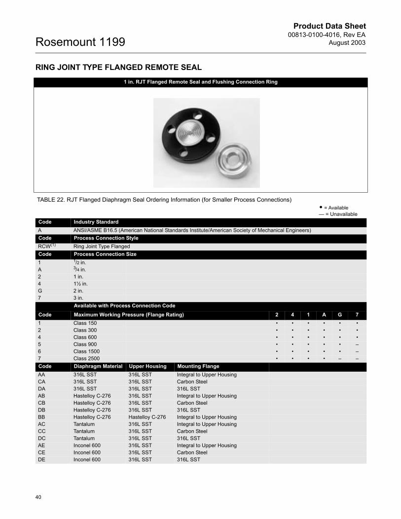
Product Data Sheet00813-0100-4016, Rev EA
August 2003Rosemount 1199
40
RING JOINT TYPE FLANGED REMOTE SEAL1 in. RJT Flanged Remote Seal and Flushing Connection Ring
TABLE 22. RJT Flanged Diaphragm Seal Ordering Information (for Smaller Process Connections) • = Available� = Unavailable
Code Industry StandardA ANSI/ASME B16.5 (American National Standards Institute/American Society of Mechanical Engineers)Code Process Connection StyleRCW(1) Ring Joint Type Flanged Code Process Connection Size1 1/2 in.A 3/4 in. 2 1 in.4 1½ in. G 2 in.7 3 in.
Available with Process Connection CodeCode Maximum Working Pressure (Flange Rating) 2 4 1 A G 71 Class 150 � � � � � �2 Class 300 � � � � � �4 Class 600 � � � � � �5 Class 900 � � � � � �6 Class 1500 � � � � � �7 Class 2500 � � � � � �Code Diaphragm Material Upper Housing Mounting FlangeAA 316L SST 316L SST Integral to Upper HousingCA 316L SST 316L SST Carbon SteelDA 316L SST 316L SST 316L SSTAB Hastelloy C-276 316L SST Integral to Upper HousingCB Hastelloy C-276 316L SST Carbon SteelDB Hastelloy C-276 316L SST 316L SSTBB Hastelloy C-276 Hastelloy C-276 Integral to Upper HousingAC Tantalum 316L SST Integral to Upper HousingCC Tantalum 316L SST Carbon SteelDC Tantalum 316L SST 316L SSTAE Inconel 600 316L SST Integral to Upper HousingCE Inconel 600 316L SST Carbon SteelDE Inconel 600 316L SST 316L SST

Product Data Sheet00813-0100-4016, Rev EAAugust 2003
41
Rosemount 1199
AF 304L SST 316L SST Integral to Upper HousingCF 304L SST 316L SST Carbon SteelDF 304L SST 316L SST 316L SSTAJ Hastelloy B 316L SST Integral to Upper HousingCJ Hastelloy B 316L SST Carbon SteelDJ Hastelloy B 316L SST 316L SSTAK Alloy 20 316L SST Integral to Upper HousingCK Alloy 20 316L SST Carbon SteelDK Alloy 20 316L SST 316L SSTAP Nickel 201 316L SST Integral to Upper HousingCP Nickel 201 316L SST Carbon SteelDP Nickel 201 316L SST 316L SSTAV Monel 400 316L SST Integral to Upper HousingCV Monel 400 316L SST Carbon SteelDV Monel 400 316L SST 316L SSTTH(2) Titanium Gr. 4 Titanium Gr. 4 Integral to Upper HousingRH(2)(3) Titanium Gr. 4 Titanium Gr. 4 316L SST
Code Flushing Connection Ring Material (Lower Housing)(4) A 316 SSTB Hastelloy C-276D Carbon SteelF 304 SSTH Titanium Gr. 4J Hastelloy B6 Nickel 201V Monel 400E Inconel 6001 Inconel 625K Alloy 20
Code Flushing Options1 One ¼-in. Flushing Connection3 Two ¼-in. Flushing Connections5 No Flushing Connection7 One 1/2-in. Flushing Connection 9 Two 1/2-in. Flushing Connections
Code OptionsB(5) Extra Fill for Cold Temperature Applications C(6) 0.006-in. Diaphragm Thickness (316L SST and Hastelloy C-276 diaphragms only, for abrasive applications)D Hastelloy Plug in Flushing Connections G SST Plug in Flushing Connections H SST Drain/Vent in Flushing Connections
V(7) Teflon (PTFE) Coated Diaphragm for nonstick purposes (316L SST and Hastelloy C-276 diaphragms only)3 304 SST BoltsT NACE MR-01-75 4 0.002-in. Diaphragm thickness (316L SST and Hastelloy C-276 diaphragms only)
(1) Shaded areas indicate special orders. Consult your Rosemount representative for configuration availability, performance effects, and lead time.
(2) Not available with welded capillary or direct mount connections.
(3) Operating temperature limited to 150 °C (302 °F).
(4) Supplied with C4401 gasket unless noted otherwise.
(5) For seal assemblies that will be used in cold ambient temperature applications, contact your Rosemount representative or reference SOAP 2000 for assistance.
(6) May cause adverse seal temperature effects. Consult your Rosemount representative for assistance.
(7) Not available with transmitter option code Q8, for Material Traceability per DIN EN10204 3.1.B of the transmitter/diaphragm seal assembly.
TABLE 22. RJT Flanged Diaphragm Seal Ordering Information (for Smaller Process Connections) • = Available� = Unavailable
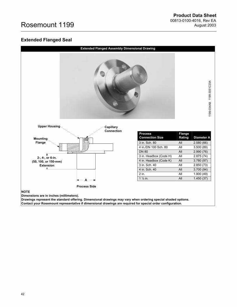
Product Data Sheet00813-0100-4016, Rev EA
August 2003Rosemount 1199
42
Extended Flanged Seal Extended Flanged Assembly Dimensional Drawing
NOTEDimensions are in inches (millimeters).Drawings represent the standard offering. Dimensional drawings may vary when ordering special shaded options. Contact your Rosemount representative if dimensional drawings are required for special order configuration.
1199
-034
AB11
99-3
051C
23A
Upper Housing
Mounting Flange
2-, 4-, or 6-in.(50, 100, or 150-mm)
Extension
A
CapillaryConnection
Process Side
ProcessConnection Size
FlangeRating Diameter A
3 in. Sch. 80 All 2.580 (66)4 in./DN 100 Sch. 80 All 3.500 (89)DN 80 All 2.990 (76)3 in. Headbox (Code H) All 2.875 (74)4 in. Headbox (Code K) All 3.780 (97)3 in. Sch. 40 All 2.850 (73)4 in. Sch. 40 All 3.700 (94)2 in. All 1.900 (49)1 ½ in. All 1.450 (37)
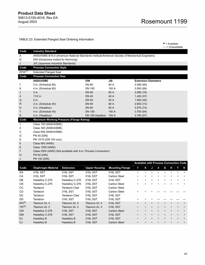
Product Data Sheet00813-0100-4016, Rev EAAugust 2003
43
Rosemount 1199
TABLE 23. Extended Flanged Seal Ordering Information • = Available� = Unavailable
Code Industry StandardA ANSI/ASME B16.5 (American National Standards Institute/American Society of Mechanical Engineers)D DIN (Deutsches Institut fur Normung)J JIS (Japanese Industrial Standards)Code Process Connection StyleEFW(1) Extended Flanged SealCode Process Connection Size
ANSI/ASME DIN JIS Extension Diameters7 3 in. (Schedule 80) DN 80 80 A 2.580 (66)9 4 in. (Schedule 80) DN 100 100 A 3.500 (89)J 3 in. DN 80 80 A 2.990 (76)4 11/2 in DN 40 40 A 1.450 (37)G 2 in. DN 50 50 A 1.900 (49)R 3 in. (Schedule 40) DN 80 80 A 2.850 (73)H 3 in. (Headbox) DN 80 80 A 2.875 (74)T 4 in. (Schedule 40) DN 100 100 A 3.700 (94)K 4 in. (Headbox) DN 100 Headbox 100 A 3.780 (97)Code Maximum Working Pressure (Flange Rating)1 Class 150 (ANSI/ASME) 2 Class 300 (ANSI/ASME) 4 Class 600 (ANSI/ASME) G PN 40 (DIN)E PN 10/16 (DN 100 only)5 Class 900 (ANSI)6 Class 1500 (ANSI)7 Class 2500 (ANSI) (Not available with 4-in. Process Connection)H PN 64 (DIN)J PN 100 (DIN)
Available with Process Connection Code
Code Diaphragm Material Extension Upper Housing Mounting Flange 7 9 J 4 G H T KDA 316L SST 316L SST 316L SST 316L SST � � � � � � � �CA 316L SST 316L SST 316L SST Carbon Steel � � � � � � � �DB Hastelloy C-276 Hastelloy C-276 316L SST 316L SST � � � � � � � �CB Hastelloy C-276 Hastelloy C-276 316L SST Carbon Steel � � � � � � � �CC Tantalum Tantalum Clad 316L SST Carbon SteelCD Tantalum 316L SST 316L SST Carbon Steel � � � � � � � �DC Tantalum Tantalum Clad 316L SST 316L SSTDD Tantalum 316L SST 316L SST 316L SST � � � � � � � �RH(2) Titanium Gr. 4 Titanium Gr. 4 Titanium Gr. 4 316L SST � � � � � � � �YR(2) Titanium Gr. 2 Titanium Gr. 2 Titanium Gr. 2 316L SST � � � � � � � �CM Hastelloy C-276 316L SST 316L SST Carbon Steel � � � � � � � �DM Hastelloy C-276 316L SST 316L SST 316L SST � � � � � � � �DJ Hastelloy B Hastelloy B 316L SST 316L SST � � � � � � � �CJ Hastelloy B Hastelloy B 316L SST Carbon Steel � � � � � � � �
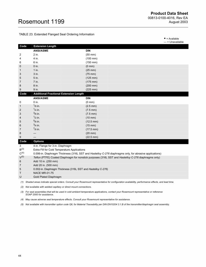
Product Data Sheet00813-0100-4016, Rev EA
August 2003Rosemount 1199
44
Code Extension LengthANSI/ASME DIN
2 2 in. (50 mm)4 4 in. (100 mm)6 6 in. (150 mm)0 0 in. (0 mm)1 1 in. (25 mm)3 3 in. (75 mm)5 5 in. (125 mm)7 7 in. (175 mm)8 8 in. (200 mm)9 9 in. (225 mm)Code Additional Fractional Extension Length
ANSI/ASME DIN0 0 in. (0 mm)1 1/8 in. (2.5 mm)2 1/4 in. (7.5 mm)3 3/8 in. (7.5 mm)4 1/2 in. (10 mm)5 5/8 in. (12.5 mm)6 3/4 in. (15 mm)7 7/8 in. (17.5 mm)8 � (20 mm)9 � (22.5 mm) Code Options 3 4-in. Flange for 3-in. DiaphragmB(3) Extra Fill for Cold Temperature ApplicationsC(4) 0.006-in. Diaphragm Thickness (316L SST and Hastelloy C-276 diaphragms only, for abrasive applications)V(5) Teflon (PTFE) Coated Diaphragm for nonstick purposes (316L SST and Hastelloy C-276 diaphragms only)6 Add 10 in. (250 mm)7 Add 20 in. (500 mm)5 0.002-in. Diaphragm Thickness (316L SST and Hastelloy C-276) T NACE MR-01-75 U Gold Plated Diaphragm
(1) Shaded areas indicate special orders. Consult your Rosemount representative for configuration availability, performance effects, and lead time.
(2) Not available with welded capillary or direct mount connections.
(3) For seal assemblies that will be used in cold ambient temperature applications, contact your Rosemount representative or reference SOAP 2000 for assistance.
(4) May cause adverse seal temperature effects. Consult your Rosemount representative for assistance.
(5) Not available with transmitter option code Q8, for Material Traceability per DIN EN10204 3.1.B of the transmitter/diaphragm seal assembly.
TABLE 23. Extended Flanged Seal Ordering Information • = Available� = Unavailable
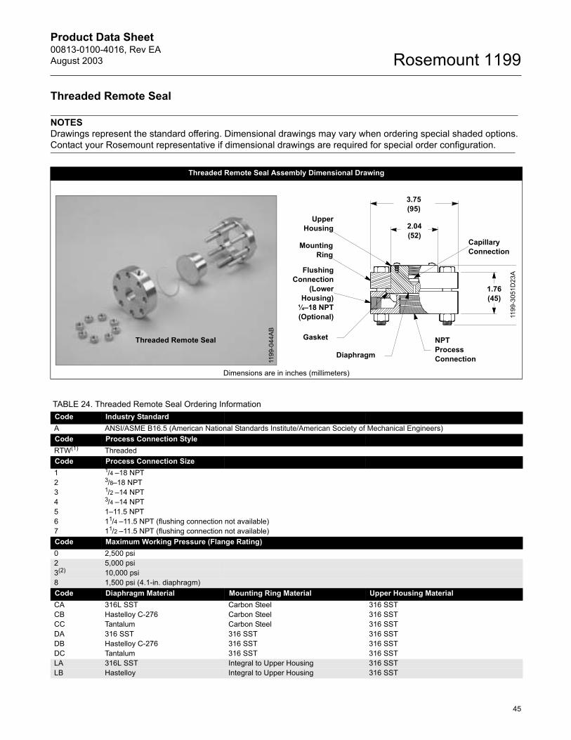
Product Data Sheet00813-0100-4016, Rev EAAugust 2003
45
Rosemount 1199
Threaded Remote Seal
NOTESDrawings represent the standard offering. Dimensional drawings may vary when ordering special shaded options. Contact your Rosemount representative if dimensional drawings are required for special order configuration.
Threaded Remote Seal Assembly Dimensional Drawing
Dimensions are in inches (millimeters)
Threaded Remote Seal
1199
-044
AB
3.75(95)
MountingRing
CapillaryConnection
FlushingConnection
(LowerHousing)
¼�18 NPT(Optional)
Gasket
Diaphragm
2.04(52)
NPTProcessConnection
UpperHousing
1.76(45)
1199
-305
1D23
A
TABLE 24. Threaded Remote Seal Ordering InformationCode Industry StandardA ANSI/ASME B16.5 (American National Standards Institute/American Society of Mechanical Engineers)Code Process Connection StyleRTW(1) ThreadedCode Process Connection Size1 1/4 �18 NPT2 3/8�18 NPT3 1/2 �14 NPT4 3/4 �14 NPT5 1�11.5 NPT6 11/4 �11.5 NPT (flushing connection not available)7 11/2 �11.5 NPT (flushing connection not available)Code Maximum Working Pressure (Flange Rating)0 2,500 psi 2 5,000 psi 3(2) 10,000 psi 8 1,500 psi (4.1-in. diaphragm)Code Diaphragm Material Mounting Ring Material Upper Housing MaterialCA 316L SST Carbon Steel 316 SSTCB Hastelloy C-276 Carbon Steel 316 SSTCC Tantalum Carbon Steel 316 SSTDA 316 SST 316 SST 316 SSTDB Hastelloy C-276 316 SST 316 SSTDC Tantalum 316 SST 316 SSTLA 316L SST Integral to Upper Housing 316 SSTLB Hastelloy Integral to Upper Housing 316 SST
Product Data Sheet00813-0100-4016, Rev EA
August 2003Rosemount 1199
46
LC Tantalum Integral to Upper Housing 316 SSTLF 304 L SST Integral to Upper Housing 316 SSTLJ Hastelloy B Integral to Upper Housing 316 SSTLP Nickel 201 Integral to Upper Housing 316 SSTLV Monel 400 Integral to Upper Housing 316 SSTTH(3) Titanium Gr. 4 Integral to Upper Housing Titanium Gr. 4Code Flushing Connection Ring (Lower Housing)(4)
A 316 SSTB Hastelloy C-276D Carbon SteelF 304L SSTH Titanium Gr. 4V Monel 400J Hastelloy BP PVC (no flushing connections allowed)Code Flushing Options 1 One ¼-in. Flushing Connection3 Two ¼-in. Flushing Connections5 No Flushing Connection7(8) One 1/2-in. Flushing Connection9(8) Two 1/2-in. Flushing ConnectionsCode Options 3(5) 300 Series SST BoltsB(6) Extra Fill for Cold Temperature Applications C(7) 0.006-in. Diaphragm Thickness (316L SST and Hastelloy C-276 diaphragms only, for abrasive applications)D Hastelloy Plug in Flushing ConnectionG SST Plug in Flushing Connection onlyH SST Drain/Vent in Flushing ConnectionJ(8) Teflon (PTFE) Gasket for lower housingK(8) Barium Sulfate-filled Teflon (PTFE) Gasket for lower housing N(5) Grafoil Gasket for lower housingR(8) Ethylene Propylene Gasket for lower housingV(9) Teflon (PTFE) Coated Diaphragm for nonstick purposes (316L SST and Hastelloy C-276 diaphragms only)T NACE MR-01-75U Gold Plated Diaphragm8 2.9-in. Diaphragm (2,500 psi maximum working pressure)1(5) Klinger Topchen 2000 Gasket2 0.002-in. Diaphragm Thickness (316L SST and Hastelloy C-276 diaphragms only)5 Monel Metal Gasket (Pressure rating 10,000 psi only)
(1) Shaded areas indicate special orders. Consult your Rosemount representative for configuration availability, performance effects, and lead time.(2) Not available with process connection size codes 4, 5, 6, or 7.(3) Not available with welded capillary or direct mount connections.(4) Supplied standard with Thermo-Tork 9000 gasket. Supplied with a C4401 gasket when any model code in a shaded area is selected. (5) Not available with 10,000 psi pressure rating.(6) For seal assemblies that will be used in cold ambient temperature applications, contact your Rosemount representative or see SOAP 2000 for assistance.(7) May cause adverse seal temperature effects. Consult your Rosemount representative for assistance.(8) Not available with 5,000 or 10,000 psi pressure rating.(9) Not available with transmitter option code Q8, for Material Traceability per DIN EN10204 3.1.B of the transmitter/diaphragm seal assembly.
TABLE 24. Threaded Remote Seal Ordering Information
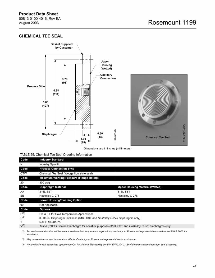
Product Data Sheet00813-0100-4016, Rev EAAugust 2003
47
Rosemount 1199
CHEMICAL TEE SEAL
Dimensions are in inches (millimeters)
TABLE 25. Chemical Tee Seal Ordering InformationCode Industry StandardN Industry SpecificCode Process Connection StyleCTW Chemical Tee Seal (Wedge flow style seal)Code Maximum Working Pressure (Flange Rating)20 300 psig Code Diaphragm Material Upper Housing Material (Wetted)AA 316L SST 316L SSTBB Hastelloy C-276 Hastelloy C-276Code Lower Housing/Flushing Option00 Not Applicable Code OptionsB(1) Extra Fill for Cold Temperature ApplicationsC(2) 0.006-in. Diaphragm thickness (316L SST and Hastelloy C-276 diaphragms only)T NACE MR-01-75V(3) Teflon (PTFE) Coated Diaphragm for nonstick purposes (316L SST and Hastelloy C-276 diaphragms only)
(1) For seal assemblies that will be used in cold ambient temperature applications, contact your Rosemount representative or reference SOAP 2000 for assistance.
(2) May cause adverse seal temperature effects. Contact your Rosemount representative for assistance.
(3) Not available with transmitter option code Q8, for Material Traceability per DIN EN10204 3.1.B of the transmitter/diaphragm seal assembly.
Capillary Connection
Upper Housing(Wetted)
1.00(25)
0.50(13)
Gasket Suppliedby Customer
Diaphragm
3.78(96)
4.38(111)
5.00(127)
Process Side
1199
-033
AB
Chemical Tee Seal
1199
-305
1C26
A
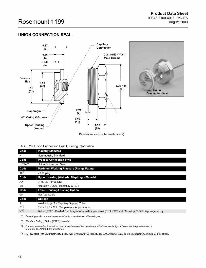
Product Data Sheet00813-0100-4016, Rev EA
August 2003Rosemount 1199
48
UNION CONNECTION SEAL
Dimensions are n inches (millimeters)
Capillary Connection
Upper Housing(Wetted)
21/8�16N2 × 25/64Male Thread
Diaphragm 0.08(2)
2.0(51)
1.65(42)
0.343(9)
0.56(14)
0.87(22)
45° O-ring V-Groove
2.25 Hex(57)
1.12(28)
0.62(16)
ProcessSide
Union Connection Seal
TABLE 26. Union Connection Seal Ordering InformationCode Industry StandardN Non-Industry StandardCode Process Connection StyleUCW(1) Union Connection Seal Code Maximum Working Pressure (Flange Rating)10(2) 2,000 psig Code Upper Housing (Wetted) / Diaphragm MaterialAA 316L SST/316L SSTBB Hastelloy C-276 / Hastelloy C- 276Code Lower Housing/Flushing Option 00 Not Applicable Code Options1 Weld Nugget for Capillary Support TubeB(3) Extra Fill for Cold Temperature ApplicationsV(4) Teflon (PTFE) Coated Diaphragm for nonstick purposes (316L SST and Hastelloy C-276 diaphragms only)
(1) Consult your Rosemount representative for use with low calibrated spans.
(2) Standard O-ring is Teflon (PTFE) material.
(3) For seal assemblies that will be used in cold ambient temperature applications, contact your Rosemount representative or reference SOAP 2000 for assistance.
(4) Not available with transmitter option code Q8, for Material Traceability per DIN EN10204 3.1.B of the transmitter/diaphragm seal assembly.
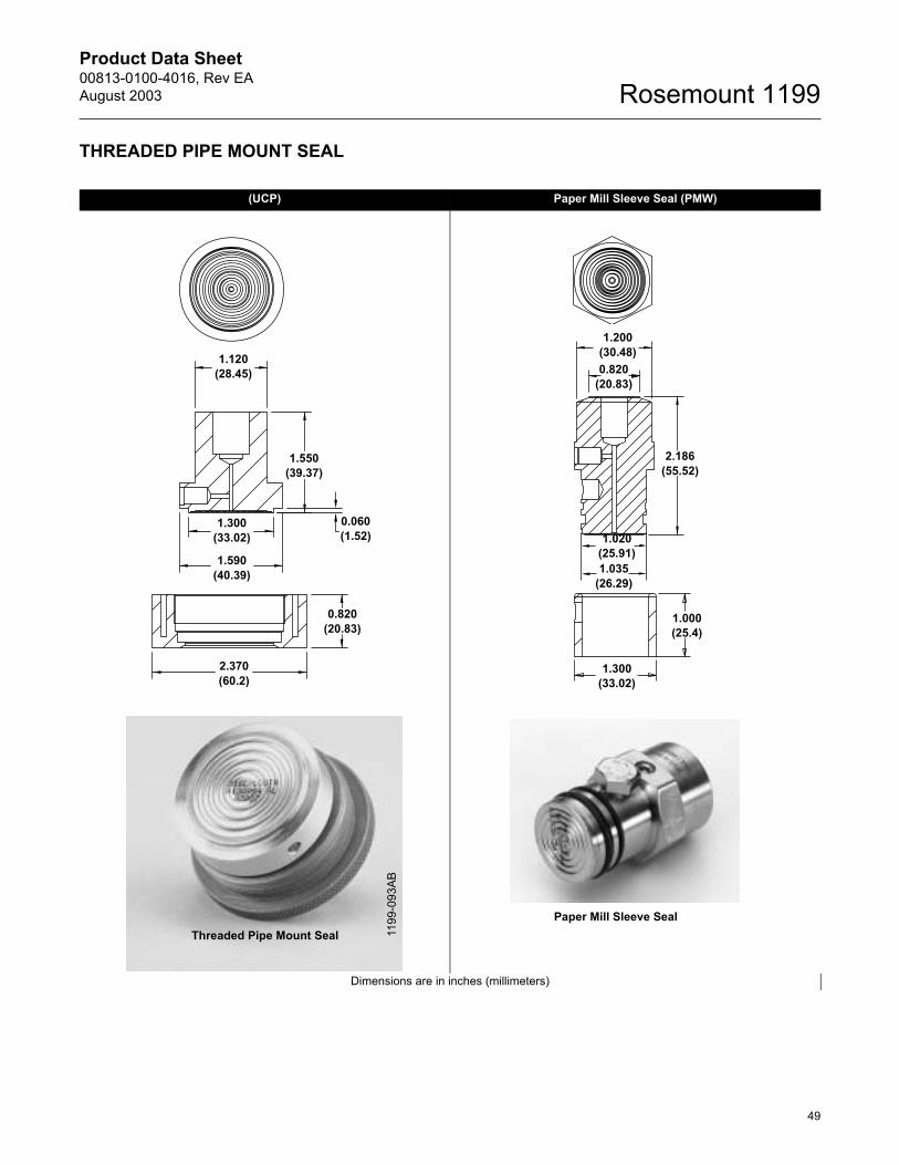
Product Data Sheet00813-0100-4016, Rev EAAugust 2003
49
Rosemount 1199
THREADED PIPE MOUNT SEAL
(UCP) Paper Mill Sleeve Seal (PMW)
Dimensions are in inches (millimeters)
1.120(28.45)
1.550(39.37)
1.300(33.02)
1.590(40.39)
0.060(1.52)
0.820(20.83)
2.370(60.2)
1.200(30.48)0.820
(20.83)
2.186(55.52)
1.020(25.91)1.035
(26.29)
1.000(25.4)
1.300(33.02)
Threaded Pipe Mount Seal 1199
-093
AB
Paper Mill Sleeve Seal
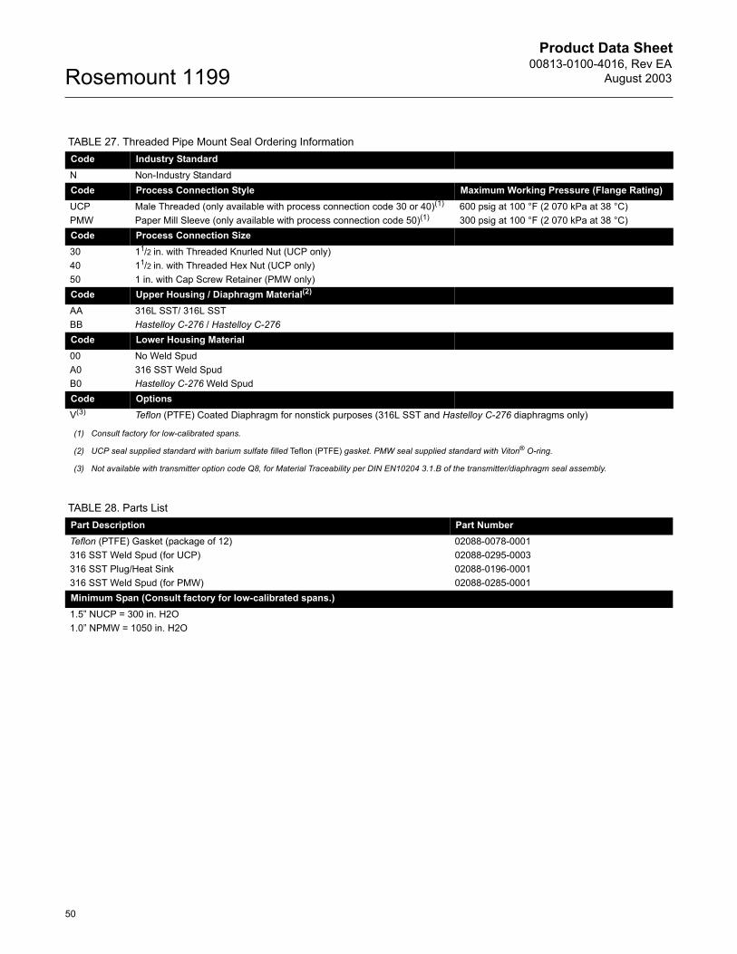
Product Data Sheet00813-0100-4016, Rev EA
August 2003Rosemount 1199
50
TABLE 27. Threaded Pipe Mount Seal Ordering InformationCode Industry StandardN Non-Industry StandardCode Process Connection Style Maximum Working Pressure (Flange Rating)UCP Male Threaded (only available with process connection code 30 or 40)(1) 600 psig at 100 °F (2 070 kPa at 38 °C)PMW Paper Mill Sleeve (only available with process connection code 50)(1) 300 psig at 100 °F (2 070 kPa at 38 °C)Code Process Connection Size30 11/2 in. with Threaded Knurled Nut (UCP only)40 11/2 in. with Threaded Hex Nut (UCP only)50 1 in. with Cap Screw Retainer (PMW only)Code Upper Housing / Diaphragm Material(2)
AA 316L SST/ 316L SSTBB Hastelloy C-276 / Hastelloy C-276Code Lower Housing Material00 No Weld SpudA0 316 SST Weld Spud B0 Hastelloy C-276 Weld SpudCode Options V(3) Teflon (PTFE) Coated Diaphragm for nonstick purposes (316L SST and Hastelloy C-276 diaphragms only)
(1) Consult factory for low-calibrated spans.
(2) UCP seal supplied standard with barium sulfate filled Teflon (PTFE) gasket. PMW seal supplied standard with Viton® O-ring.
(3) Not available with transmitter option code Q8, for Material Traceability per DIN EN10204 3.1.B of the transmitter/diaphragm seal assembly.
TABLE 28. Parts ListPart Description Part NumberTeflon (PTFE) Gasket (package of 12) 02088-0078-0001316 SST Weld Spud (for UCP) 02088-0295-0003316 SST Plug/Heat Sink 02088-0196-0001316 SST Weld Spud (for PMW) 02088-0285-0001Minimum Span (Consult factory for low-calibrated spans.)1.5� NUCP = 300 in. H2O1.0� NPMW = 1050 in. H2O
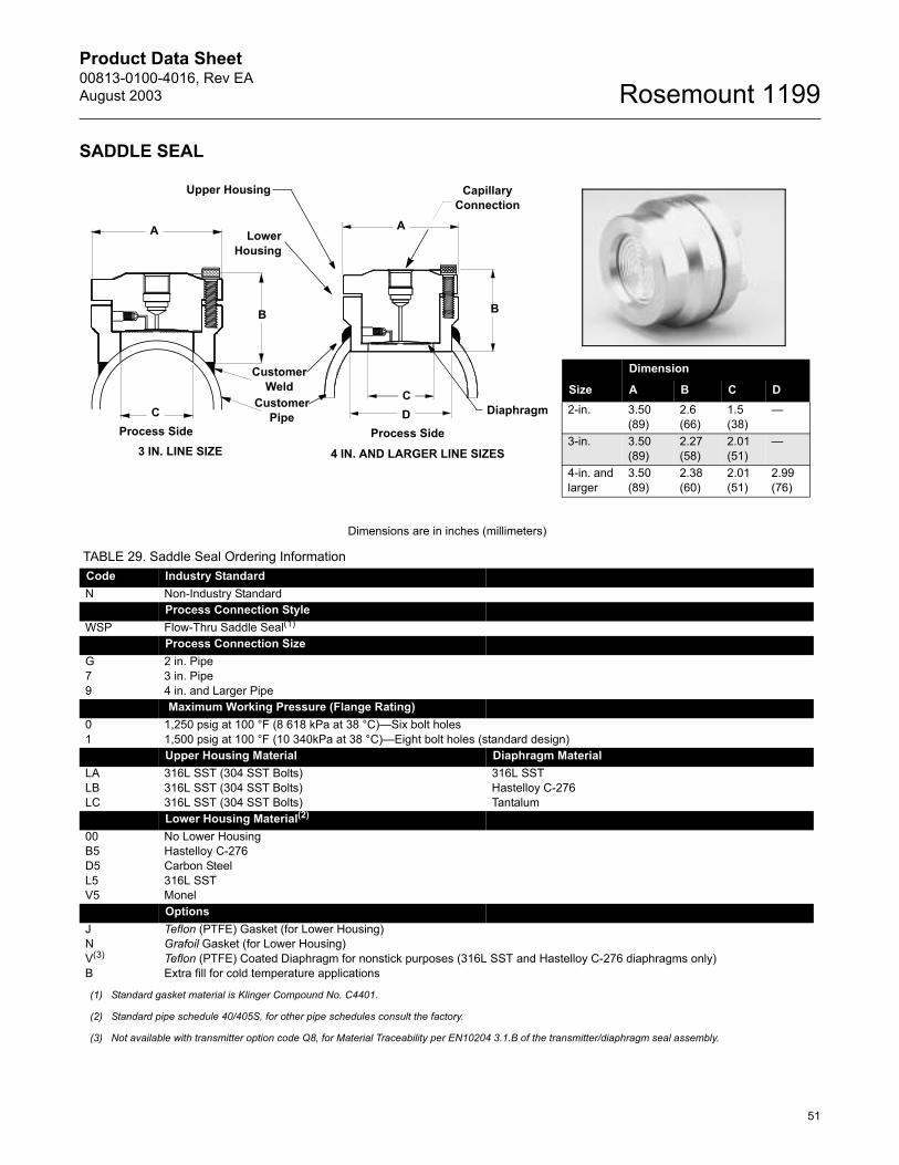
Product Data Sheet00813-0100-4016, Rev EAAugust 2003
51
Rosemount 1199
SADDLE SEAL
Dimensions are in inches (millimeters)
TABLE 29. Saddle Seal Ordering InformationCode Industry StandardN Non-Industry StandardCode Process Connection StyleWSP Flow-Thru Saddle Seal(1)
Code Process Connection SizeG 2 in. Pipe7 3 in. Pipe9 4 in. and Larger PipeCode Maximum Working Pressure (Flange Rating)0 1,250 psig at 100 °F (8 618 kPa at 38 °C)�Six bolt holes1 1,500 psig at 100 °F (10 340kPa at 38 °C)�Eight bolt holes (standard design)Code Upper Housing Material Diaphragm MaterialLA 316L SST (304 SST Bolts) 316L SSTLB 316L SST (304 SST Bolts) Hastelloy C-276LC 316L SST (304 SST Bolts) TantalumCode Lower Housing Material(2)
00 No Lower HousingB5 Hastelloy C-276D5 Carbon SteelL5 316L SSTV5 MonelCode Options J Teflon (PTFE) Gasket (for Lower Housing)N Grafoil Gasket (for Lower Housing)V(3) Teflon (PTFE) Coated Diaphragm for nonstick purposes (316L SST and Hastelloy C-276 diaphragms only)B Extra fill for cold temperature applications
(1) Standard gasket material is Klinger Compound No. C4401.
(2) Standard pipe schedule 40/405S, for other pipe schedules consult the factory.
(3) Not available with transmitter option code Q8, for Material Traceability per EN10204 3.1.B of the transmitter/diaphragm seal assembly.
A A
CC
3 IN. LINE SIZE 4 IN. AND LARGER LINE SIZES
B B
Customer Pipe
Customer Weld
Upper Housing
LowerHousing
Capillary Connection
DiaphragmDProcess SideProcess Side
Size
Dimension
A B C D2-in. 3.50
(89)2.6(66)
1.5(38)
�
3-in. 3.50(89)
2.27(58)
2.01(51)
�
4-in. and larger
3.50(89)
2.38(60)
2.01(51)
2.99(76)
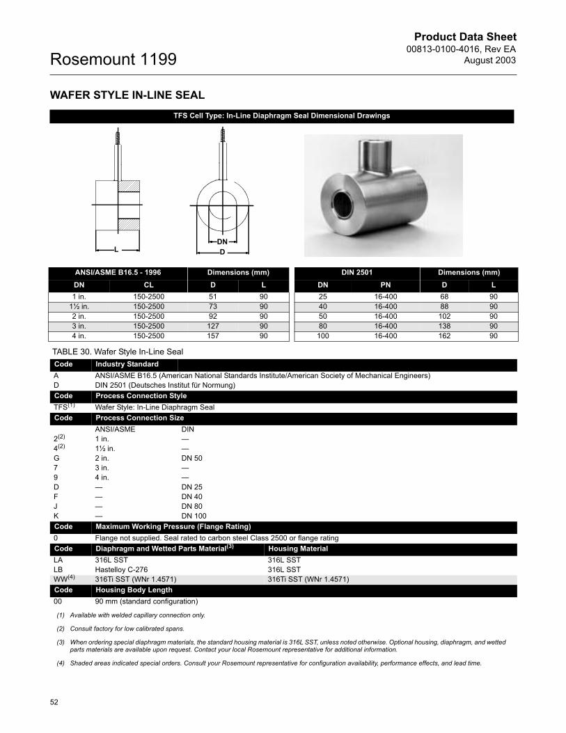
Product Data Sheet00813-0100-4016, Rev EA
August 2003Rosemount 1199
52
WAFER STYLE IN-LINE SEAL TFS Cell Type: In-Line Diaphragm Seal Dimensional Drawings
ANSI/ASME B16.5 - 1996 Dimensions (mm) DIN 2501 Dimensions (mm)DN CL D L DN PN D L1 in. 150-2500 51 90 25 16-400 68 90
1½ in. 150-2500 73 90 40 16-400 88 902 in. 150-2500 92 90 50 16-400 102 903 in. 150-2500 127 90 80 16-400 138 904 in. 150-2500 157 90 100 16-400 162 90
TABLE 30. Wafer Style In-Line SealCode Industry Standard A ANSI/ASME B16.5 (American National Standards Institute/American Society of Mechanical Engineers)D DIN 2501 (Deutsches Institut für Normung)Code Process Connection StyleTFS(1) Wafer Style: In-Line Diaphragm SealCode Process Connection Size
ANSI/ASME DIN2(2) 1 in. �4(2) 1½ in. �G 2 in. DN 507 3 in. �9 4 in. �D � DN 25F � DN 40J � DN 80K � DN 100Code Maximum Working Pressure (Flange Rating)0 Flange not supplied. Seal rated to carbon steel Class 2500 or flange ratingCode Diaphragm and Wetted Parts Material(3) Housing MaterialLA 316L SST 316L SSTLB Hastelloy C-276 316L SSTWW(4) 316Ti SST (WNr 1.4571) 316Ti SST (WNr 1.4571)Code Housing Body Length00 90 mm (standard configuration)
(1) Available with welded capillary connection only.
(2) Consult factory for low calibrated spans.
(3) When ordering special diaphragm materials, the standard housing material is 316L SST, unless noted otherwise. Optional housing, diaphragm, and wetted parts materials are available upon request. Contact your local Rosemount representative for additional information.
(4) Shaded areas indicated special orders. Consult your Rosemount representative for configuration availability, performance effects, and lead time.
L DDN

Product Data Sheet00813-0100-4016, Rev EAAugust 2003
53
Rosemount 1199
FLOW-THRU FLANGED
Dimensions are in inches (millimeters)
A
B
2.000(50.8)2.400
(60.96) 1199
-C19
5004
C1,
C19
5004
C2
Class (lb.) Nominal Pipe Size (in.)Overall Length ± 0.05 Upper to Centerline Height
�A� �B�
1501 7.00 (177.8) 2.28 (57.91)2 9.00 (228.6) 2.80 (71.12)3 11.00 (279.4) 3.50 (88.9)
TABLE 31. Flow-Thru Flanged Seal Ordering InformationCode Industry StandardA ANSI/ASME B16.5 (American National Standards Institute/American Society of Mechanical Engineers)Code Process Connection StyleWFW Flow-Thru FlangedCode Process Connection Size(1)
1 1/2 in.A 3/4 in.2 1 in.4 1 1/2 in.G 2 in.7 3 in.9 4 in.C 6 in.Code Maximum Working Pressure (Flange Rating) (1)
1 Class 150 psi2 Class 300 psi4 Class 600 psi5 Class 900 psi6 Class 1500 psi
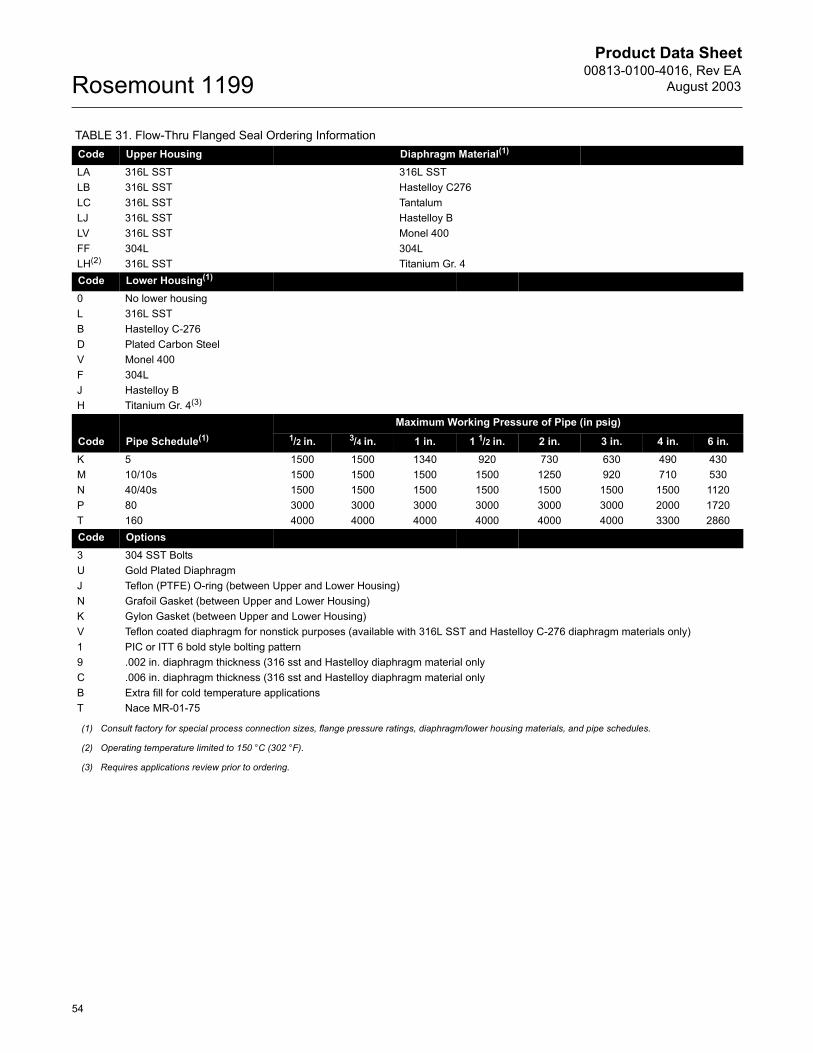
Product Data Sheet00813-0100-4016, Rev EA
August 2003Rosemount 1199
54
Code Upper Housing Diaphragm Material(1)
LA 316L SST 316L SSTLB 316L SST Hastelloy C276LC 316L SST TantalumLJ 316L SST Hastelloy BLV 316L SST Monel 400FF 304L 304LLH(2) 316L SST Titanium Gr. 4Code Lower Housing(1)
0 No lower housingL 316L SSTB Hastelloy C-276D Plated Carbon SteelV Monel 400F 304LJ Hastelloy BH Titanium Gr. 4(3)
Code Pipe Schedule(1)Maximum Working Pressure of Pipe (in psig)
1/2 in. 3/4 in. 1 in. 1 1/2 in. 2 in. 3 in. 4 in. 6 in.K 5 1500 1500 1340 920 730 630 490 430M 10/10s 1500 1500 1500 1500 1250 920 710 530N 40/40s 1500 1500 1500 1500 1500 1500 1500 1120P 80 3000 3000 3000 3000 3000 3000 2000 1720T 160 4000 4000 4000 4000 4000 4000 3300 2860Code Options3 304 SST BoltsU Gold Plated DiaphragmJ Teflon (PTFE) O-ring (between Upper and Lower Housing)N Grafoil Gasket (between Upper and Lower Housing)K Gylon Gasket (between Upper and Lower Housing)V Teflon coated diaphragm for nonstick purposes (available with 316L SST and Hastelloy C-276 diaphragm materials only)1 PIC or ITT 6 bold style bolting pattern9 .002 in. diaphragm thickness (316 sst and Hastelloy diaphragm material onlyC .006 in. diaphragm thickness (316 sst and Hastelloy diaphragm material onlyB Extra fill for cold temperature applicationsT Nace MR-01-75
(1) Consult factory for special process connection sizes, flange pressure ratings, diaphragm/lower housing materials, and pipe schedules.
(2) Operating temperature limited to 150 °C (302 °F).
(3) Requires applications review prior to ordering.
TABLE 31. Flow-Thru Flanged Seal Ordering Information
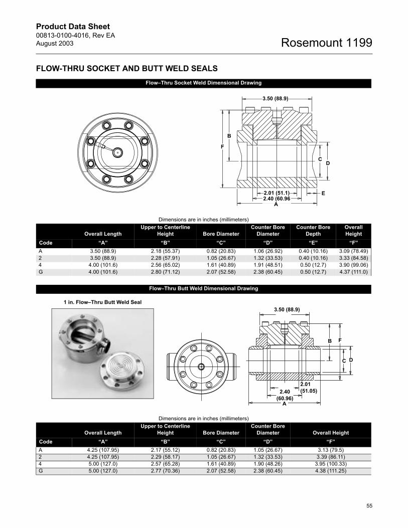
Product Data Sheet00813-0100-4016, Rev EAAugust 2003
55
Rosemount 1199
FLOW-THRU SOCKET AND BUTT WELD SEALSFlow�Thru Socket Weld Dimensional Drawing
Dimensions are in inches (millimeters)
Overall LengthUpper to Centerline
Height Bore DiameterCounter Bore
DiameterCounter Bore
DepthOverall Height
Code �A� �B� �C� �D� �E� �F�A 3.50 (88.9) 2.18 (55.37) 0.82 (20.83) 1.06 (26.92) 0.40 (10.16) 3.09 (78.49)2 3.50 (88.9) 2.28 (57.91) 1.05 (26.67) 1.32 (33.53) 0.40 (10.16) 3.33 (84.58)4 4.00 (101.6) 2.56 (65.02) 1.61 (40.89) 1.91 (48.51) 0.50 (12.7) 3.90 (99.06)G 4.00 (101.6) 2.80 (71.12) 2.07 (52.58) 2.38 (60.45) 0.50 (12.7) 4.37 (111.0)
Flow�Thru Butt Weld Dimensional Drawing
Dimensions are in inches (millimeters)
Overall LengthUpper to Centerline
Height Bore DiameterCounter Bore
Diameter Overall HeightCode �A� �B� �C� �D� �F�A 4.25 (107.95) 2.17 (55.12) 0.82 (20.83) 1.05 (26.67) 3.13 (79.5)2 4.25 (107.95) 2.29 (58.17) 1.05 (26.67) 1.32 (33.53) 3.39 (86.11)4 5.00 (127.0) 2.57 (65.28) 1.61 (40.89) 1.90 (48.26) 3.95 (100.33)G 5.00 (127.0) 2.77 (70.36) 2.07 (52.58) 2.38 (60.45) 4.38 (111.25)
F
B
CD
2.01 (51.1)2.40 (60.96
A
3.50 (88.9)
E
3.50 (88.9)
2.01(51.05)2.40
(60.96)A
B
C D
F
1 in. Flow�Thru Butt Weld Seal
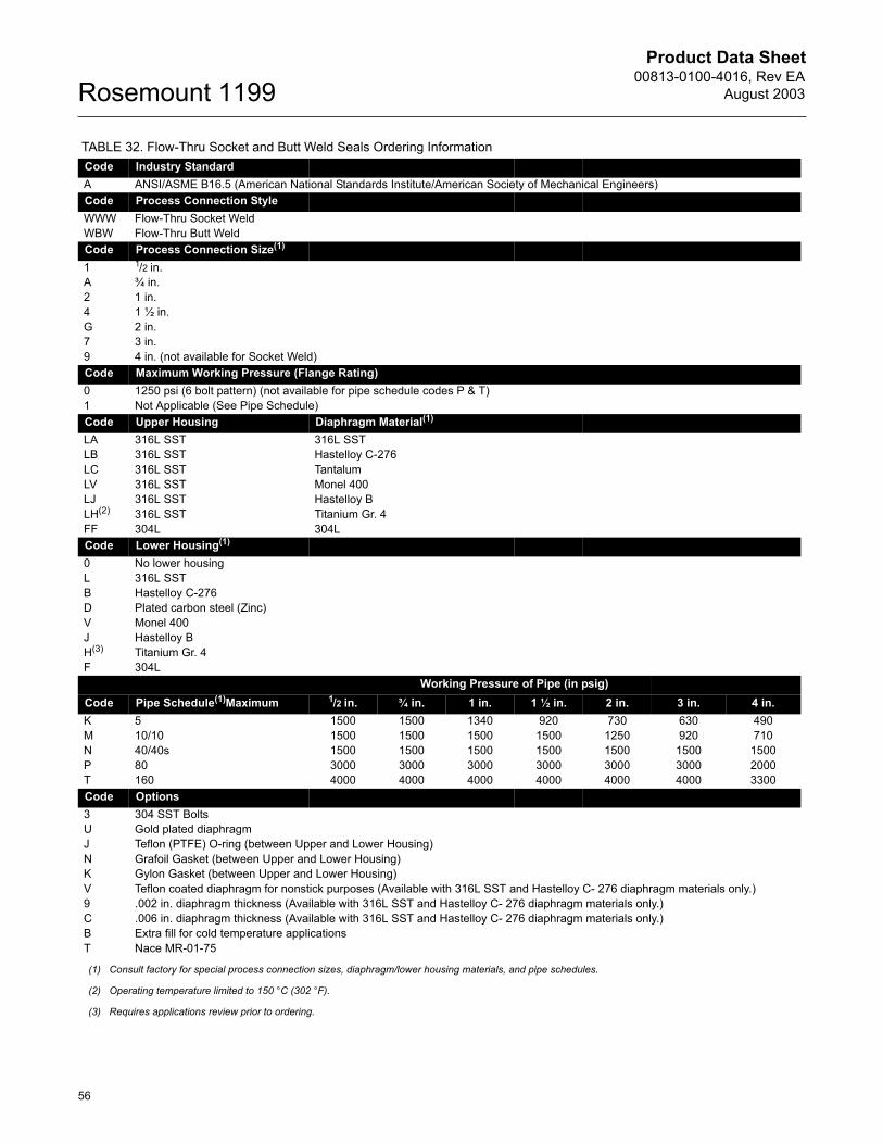
Product Data Sheet00813-0100-4016, Rev EA
August 2003Rosemount 1199
56
TABLE 32. Flow-Thru Socket and Butt Weld Seals Ordering InformationCode Industry StandardA ANSI/ASME B16.5 (American National Standards Institute/American Society of Mechanical Engineers)Code Process Connection StyleWWW Flow-Thru Socket WeldWBW Flow-Thru Butt WeldCode Process Connection Size(1)
1 1/2 in.A ¾ in.2 1 in.4 1 ½ in.G 2 in.7 3 in. 9 4 in. (not available for Socket Weld)Code Maximum Working Pressure (Flange Rating)0 1250 psi (6 bolt pattern) (not available for pipe schedule codes P & T)1 Not Applicable (See Pipe Schedule)Code Upper Housing Diaphragm Material(1)
LA 316L SST 316L SSTLB 316L SST Hastelloy C-276LC 316L SST TantalumLV 316L SST Monel 400LJ 316L SST Hastelloy BLH(2) 316L SST Titanium Gr. 4FF 304L 304LCode Lower Housing(1)
0 No lower housing L 316L SSTB Hastelloy C-276D Plated carbon steel (Zinc)V Monel 400J Hastelloy BH(3) Titanium Gr. 4F 304L
Working Pressure of Pipe (in psig)Code Pipe Schedule(1)Maximum 1/2 in. ¾ in. 1 in. 1 ½ in. 2 in. 3 in. 4 in.K 5 1500 1500 1340 920 730 630 490M 10/10 1500 1500 1500 1500 1250 920 710N 40/40s 1500 1500 1500 1500 1500 1500 1500P 80 3000 3000 3000 3000 3000 3000 2000T 160 4000 4000 4000 4000 4000 4000 3300Code Options3 304 SST BoltsU Gold plated diaphragmJ Teflon (PTFE) O-ring (between Upper and Lower Housing)N Grafoil Gasket (between Upper and Lower Housing)K Gylon Gasket (between Upper and Lower Housing)V Teflon coated diaphragm for nonstick purposes (Available with 316L SST and Hastelloy C- 276 diaphragm materials only.)9 .002 in. diaphragm thickness (Available with 316L SST and Hastelloy C- 276 diaphragm materials only.)C .006 in. diaphragm thickness (Available with 316L SST and Hastelloy C- 276 diaphragm materials only.)B Extra fill for cold temperature applicationsT Nace MR-01-75
(1) Consult factory for special process connection sizes, diaphragm/lower housing materials, and pipe schedules.
(2) Operating temperature limited to 150 °C (302 °F).
(3) Requires applications review prior to ordering.
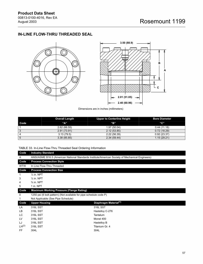
Product Data Sheet00813-0100-4016, Rev EAAugust 2003
57
Rosemount 1199
IN-LINE FLOW-THRU THREADED SEAL
Dimensions are in inches (millimeters)
A
B
C
3.50 (88.9)
2.01 (51.05)
2.40 (60.96)
CodeOverall Length Upper to Centerline Height Bore Diameter
�A� �B� �C�1 2.62 (66.55) 1.97 (50.04) 0.44 (11.18)3 2.91 (73.91) 2.12 (53.85) 0.72 (18.29)4 3.13 (79.5) 2.22 (56.39) 0.92 (23.37)5 3.38 (85.85) 2.34 (59.44) 1.15 (29.21)
TABLE 33. In-Line Flow-Thru Threaded Seal Ordering InformationCode Industry StandardA ANSI/ASME B16.5 (American National Standards Institute/American Society of Mechanical Engineers)Code Process Connection StyleWTW In Line Flow-Thru ThreadedCode Process Connection Size1 ¼ in. NPT3 ½ in. NPT4 ¾ in. NPT5 1 in. NPTCode Maximum Working Pressure (Flange Rating)0 1250 psi (6 bolt pattern) (Not available for pipe schedule code P)1 Not Applicable (See Pipe Schedule)Code Upper Housing Diaphragm Material(1)
LA 316L SST 316L SSTLB 316L SST Hastelloy C-276LC 316L SST TantalumLV 316L SST Monel 400LJ 316L SST Hastelloy BLH(2) 316L SST Titanium Gr. 4FF 304L 304L

Product Data Sheet00813-0100-4016, Rev EA
August 2003Rosemount 1199
58
Code Lower Housing(1)
0 No lower housing L 316L SSTB Hastelloy C-276D Plated carbon steel (Zinc)V Monel 400J Hastelloy BH(3) Titanium Gr. 4F 304LCode Pipe Schedule(1) Maximum Working of Pressure PipeP 80 3000 psiN 40/40s 1,500 psiCode Options3 304 SST BoltsU Gold plated diaphragmJ Teflon (PTFE) O-ring (between Upper and Lower Housing)N Grafoil Gasket (between Upper and Lower Housing)K Gylon Gasket (between Upper and Lower Housing)V Teflon coated diaphragm for nonstick purposes (Available with 316L SST and Hastelloy C- 276 diaphragm materials only.)9 .002 in. diaphragm thickness (Available with 316L SST and Hastelloy C- 276 diaphragm materials only.)C .006 in. diaphragm thickness (Available with 316L SST and Hastelloy C- 276 diaphragm materials only.)B Extra fill for cold temperature applicationsT Nace MR-01-75
(1) Consult factory for special diaphragm materials, lower housing materials, and pipe schedules.
(2) Operating temperature limited to 150 °C (302 °F).
(3) Requires applications review prior to ordering.
TABLE 33. In-Line Flow-Thru Threaded Seal Ordering Information

Product Data Sheet00813-0100-4016, Rev EAAugust 2003
59
Rosemount 1199
Sanitary Seal AssembliesTRI-CLAMP® IN-LINE SEAL
Dimensional Drawing for VCS Sanitary In-Line Diaphragm Seal
Dimensions are in inches (millimeters)
DN Max. Working PressureDimensions (inches)
0d 0D L1 in. 600 psi 0.87 1.99 3.541½ in. 600 psi 1.37 1.99 3.542 in. 600 psi 1.87 2.52 3.543 in. 600 psi 2.87 3.58 3.544 in. 600 psi 3.83 4.69 3.54
TABLE 34. Tri-Clamp In-Line Seal Ordering InformationCode Industry StandardS Sanitary (Conforms to 3-A Standard 74-02)Code Process Connection Style VCS(1)(2) Tri-Clamp In-Line Seal Maximum Working Pressure: 600 psi (4140 kPa)(3)
Code Process Connection Size20(4) 1 in.30(4) 1½ in.50 2 in.70 3 in.90 4 in.Code Diaphragm Material(5) Housing MaterialLA00 316L SST 316L SSTWW(1) 316Ti SST (WNr 1.4571) 316Ti SST (WNr 1.4571)Code Options P Non-Sanitary Fill Fluid (Does not conform to 3-A standard 7)H 20 µin. (0.5 µm) Ra diaphragm surface finishG(6) 15 µin. (0.375 µm) Ra diaphragm surface finish6 Electropolishing
(1) Shaded areas indicate special orders. Consult your Rosemount representative for configuration availability, performance effects, and lead time.
(2) Gasket and clamp are furnished by the user. The maximum working pressure is dependent upon the clamp pressure rating.
(3) Available with welded capillary connection only.
(4) Consult factory for low calibrated spans.
(5) When ordering optional diaphragm materials, the standard housing material is 316L SST. Optional housing, diaphragm and wetted parts materials are available upon request. Contact your local Rosemount representative for additional information.
(6) Requires Option code 6, electropolishing.
C20
240A
1.5 (38,1)
3.54 (90,0)
Process wetted surface finish max. Ra of 32 µ in.
OdOD
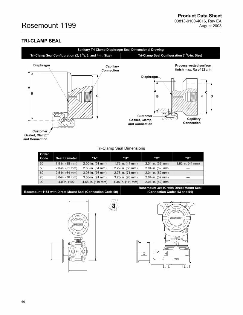
Product Data Sheet00813-0100-4016, Rev EA
August 2003Rosemount 1199
60
TRI-CLAMP SEALSanitary Tri-Clamp Diaphragm Seal Dimensional Drawing
Tri-Clamp Seal Configuration (2, 21/2, 3, and 4-in. Size) Tri-Clamp Seal Configuration (11/2-in. Size)
Rosemount 1151 with Direct Mount Seal (Connection Code 99)Rosemount 3051C with Direct Mount Seal
(Connection Codes 93 and 94)
A
BC
CapillaryConnection
Diaphragm
CustomerGasket, Clamp,
and Connection
CapillaryConnection
Diaphragm
CustomerGasket, Clamp,
and Connection
AB
CD
Process wetted surface finish max. Ra of 32 µ in.
Tri-Clamp Seal DimensionsOrder Code Seal Diameter �A� �B� �C� �D�30 1.5-in. (38 mm) 2.00-in. (51 mm) 1.72-in. (44 mm) 2.04-in. (52) mm 1.62-in. (41 mm)50 2.0-in. (51 mm) 2.50-in. (64 mm) 2.22-in. (56 mm) 2.04-in. (52) mm �60 2.5-in. (64 mm) 3.05-in. (76 mm) 2.78-in. (71 mm) 2.04-in. (52 mm) �70 3.0-in. (76 mm) 3.58-in. (91 mm) 3.28-in. (93 mm) 2.04-in. (52 mm) �90 4.0-in. (102 4.68-in. (119 mm) 4.35-in. (111 mm) 2.04-in. (52) mm �
R
37-0174-02
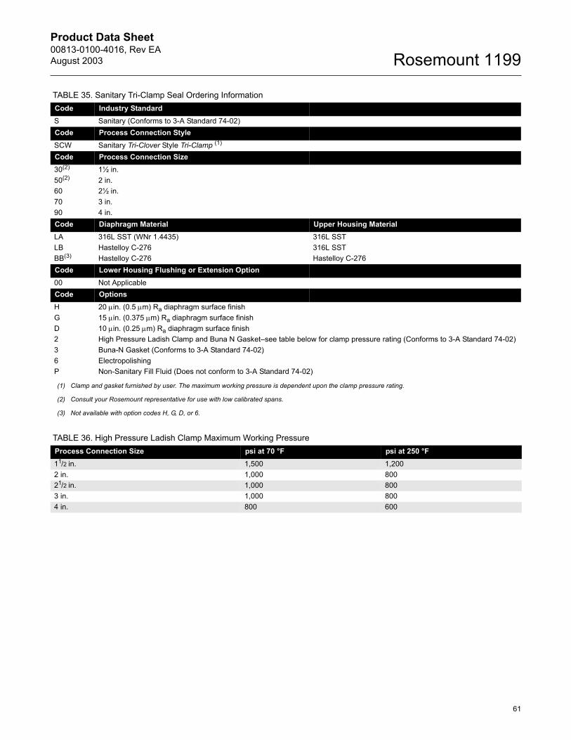
Product Data Sheet00813-0100-4016, Rev EAAugust 2003
61
Rosemount 1199
TABLE 35. Sanitary Tri-Clamp Seal Ordering InformationCode Industry StandardS Sanitary (Conforms to 3-A Standard 74-02)Code Process Connection StyleSCW Sanitary Tri-Clover Style Tri-Clamp (1)
Code Process Connection Size 30(2) 1½ in.50(2) 2 in.60 2½ in.70 3 in.90 4 in.Code Diaphragm Material Upper Housing MaterialLA 316L SST (WNr 1.4435) 316L SSTLB Hastelloy C-276 316L SSTBB(3) Hastelloy C-276 Hastelloy C-276Code Lower Housing Flushing or Extension Option 00 Not Applicable Code Options H 20 µin. (0.5 µm) Ra diaphragm surface finishG 15 µin. (0.375 µm) Ra diaphragm surface finishD 10 µin. (0.25 µm) Ra diaphragm surface finish2 High Pressure Ladish Clamp and Buna N Gasket�see table below for clamp pressure rating (Conforms to 3-A Standard 74-02)3 Buna-N Gasket (Conforms to 3-A Standard 74-02)6 ElectropolishingP Non-Sanitary Fill Fluid (Does not conform to 3-A Standard 74-02)
(1) Clamp and gasket furnished by user. The maximum working pressure is dependent upon the clamp pressure rating.
(2) Consult your Rosemount representative for use with low calibrated spans.
(3) Not available with option codes H, G, D, or 6.
TABLE 36. High Pressure Ladish Clamp Maximum Working Pressure Process Connection Size psi at 70 °F psi at 250 °F11/2 in. 1,500 1,2002 in. 1,000 80021/2 in. 1,000 8003 in. 1,000 8004 in. 800 600
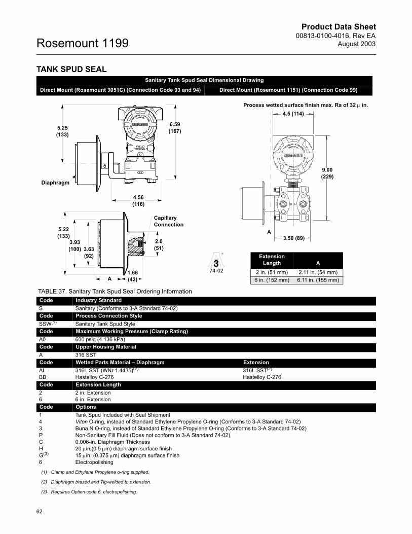
Product Data Sheet00813-0100-4016, Rev EA
August 2003Rosemount 1199
62
TANK SPUD SEAL Sanitary Tank Spud Seal Dimensional Drawing
Direct Mount (Rosemount 3051C) (Connection Code 93 and 94) Direct Mount (Rosemount 1151) (Connection Code 99)
TABLE 37. Sanitary Tank Spud Seal Ordering InformationCode Industry StandardS Sanitary (Conforms to 3-A Standard 74-02)Code Process Connection StyleSSW(1) Sanitary Tank Spud StyleCode Maximum Working Pressure (Clamp Rating)A0 600 psig (4 136 kPa)Code Upper Housing MaterialA 316 SSTCode Wetted Parts Material � Diaphragm Extension AL 316L SST (WNr 1.4435)(2) 316L SST(2)
BB Hastelloy C-276 Hastelloy C-276Code Extension Length2 2 in. Extension6 6 in. ExtensionCode Options1 Tank Spud Included with Seal Shipment4 Viton O-ring, instead of Standard Ethylene Propylene O-ring (Conforms to 3-A Standard 74-02)3 Buna N O-ring, instead of Standard Ethylene Propylene O-ring (Conforms to 3-A Standard 74-02)P Non-Sanitary Fill Fluid (Does not conform to 3-A Standard 74-02)C 0.006-in. Diaphragm ThicknessH 20 µin.(0.5 µm) diaphragm surface finishG(3) 15 µin. (0.375 µm) diaphragm surface finish6 Electropolishing
(1) Clamp and Ethylene Propylene o-ring supplied.
(2) Diaphragm brazed and Tig-welded to extension.
(3) Requires Option code 6, electropolishing.
Diaphragm
6.59(167)
4.56(116)
5.25 (133)
4.5 (114)
A
Process wetted surface finish max. Ra of 32 µ in.
3.50 (89)
9.00 (229)
5.22(133)
3.63(92)
3.93(100)
A1.66(42)
2.0(51)
Capillary Connection
ExtensionLength A
2 in. (51 mm) 2.11 in. (54 mm) 6 in. (152 mm) 6.11 in. (155 mm)
R
37-0174-02
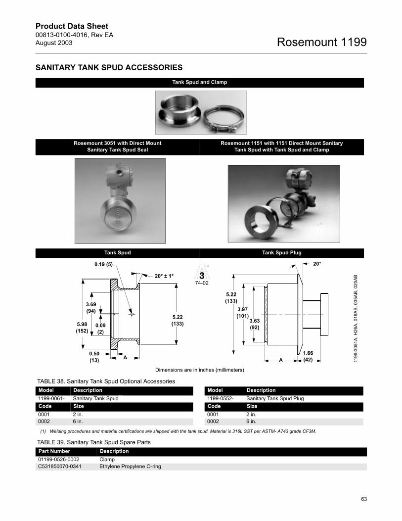
Product Data Sheet00813-0100-4016, Rev EAAugust 2003
63
Rosemount 1199
SANITARY TANK SPUD ACCESSORIES Tank Spud and Clamp
Rosemount 3051 with Direct Mount Sanitary Tank Spud Seal
Rosemount 1151 with 1151 Direct Mount Sanitary Tank Spud with Tank Spud and Clamp
Tank Spud Tank Spud Plug
Dimensions are in inches (millimeters)
TABLE 38. Sanitary Tank Spud Optional AccessoriesModel Description Model Description1199-0061- Sanitary Tank Spud(1)
(1) Welding procedures and material certifications are shipped with the tank spud. Material is 316L SST per ASTM- A743 grade CF3M.
1199-0552- Sanitary Tank Spud PlugCode Size Code Size0001 2 in. 0001 2 in.0002 6 in. 0002 6 in.
TABLE 39. Sanitary Tank Spud Spare PartsPart Number Description01199-0526-0002 ClampC531850070-0341 Ethylene Propylene O-ring
0.50(13)
0.09(2)
A
20° ± 1°
0.19 (5)
5.98(152)
5.22(133)
3.69(94)
R
37-0174-02
1.66(42)
20°
A
5.22(133)
3.63(92)
3.97(101)
1199
-305
1A, H
26A,
018
AB, 0
35AB
, 020
AB
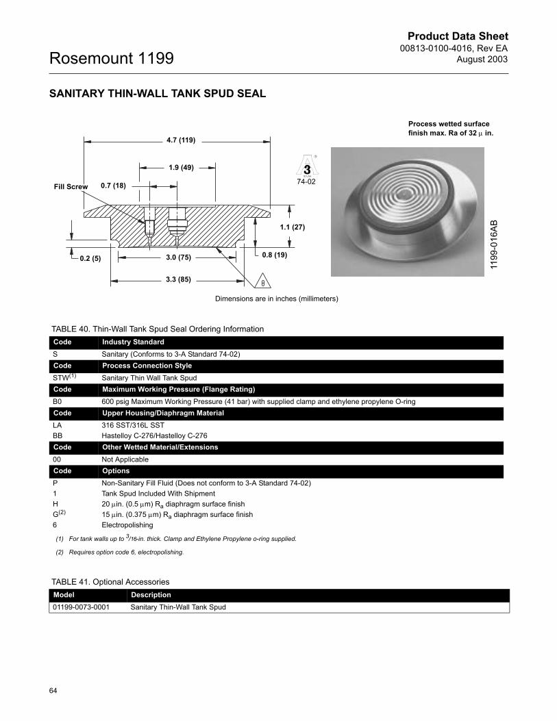
Product Data Sheet00813-0100-4016, Rev EA
August 2003Rosemount 1199
64
SANITARY THIN-WALL TANK SPUD SEAL
Dimensions are in inches (millimeters)
R
37-01
74-02
1.9 (49)
4.7 (119)
0.7 (18)Fill Screw
0.2 (5)
1.1 (27)
0.8 (19)3.0 (75)
3.3 (85)
1199
-016
AB
Process wetted surface finish max. Ra of 32 µ in.
TABLE 40. Thin-Wall Tank Spud Seal Ordering InformationCode Industry StandardS Sanitary (Conforms to 3-A Standard 74-02)Code Process Connection StyleSTW(1) Sanitary Thin Wall Tank SpudCode Maximum Working Pressure (Flange Rating)B0 600 psig Maximum Working Pressure (41 bar) with supplied clamp and ethylene propylene O-ringCode Upper Housing/Diaphragm MaterialLA 316 SST/316L SSTBB Hastelloy C-276/Hastelloy C-276Code Other Wetted Material/Extensions 00 Not ApplicableCode Options P Non-Sanitary Fill Fluid (Does not conform to 3-A Standard 74-02)1 Tank Spud Included With ShipmentH 20 µin. (0.5 µm) Ra diaphragm surface finishG(2) 15 µin. (0.375 µm) Ra diaphragm surface finish6 Electropolishing
(1) For tank walls up to 3/16-in. thick. Clamp and Ethylene Propylene o-ring supplied.
(2) Requires option code 6, electropolishing.
TABLE 41. Optional AccessoriesModel Description01199-0073-0001 Sanitary Thin-Wall Tank Spud

Product Data Sheet00813-0100-4016, Rev EAAugust 2003
65
Rosemount 1199
CHERRY-BURRELL� �I� LINE SEAL
Diameter (Nominal)
Dimensions
�A� �B� �C� �D�2 in. 1.62-in. (41 mm) 1.59-in. (40 mm) 2.24-in. (57 mm) 2.64-in. (67 mm)3 in. Consult Factory 1.24-in. (31 mm) 3.30-in. (84 mm) 3.87-in. (98 mm)
Diaphragm
CapillaryConnection
A
D
C
B
R
37-0174-02
1199
-102
AB11
99-9
050A
3A
Process wetted surface finish max. Ra of 32 µ in
TABLE 42. Cherry-Burrell �I� Line Seals Ordering InformationCode Industry StandardS Sanitary (Conforms to 3-A Standard 74-02)Code Process Connection StyleSHP(1) Sanitary Cherry-Burrell �I� Line Style Maximum Working Pressure 500 psigCode Process Connection Size50(2) 2 in. 70 3 in.Code Upper Housing/Diaphragm Material AA 316 SST/316L SSTBB Hastelloy C-276/Hastelloy C-276Code Lower Housing/Flushing Option00 Not ApplicableCode Options P Non-Sanitary Fill Fluid (Does not conform to 3-A Standard 74-02)
(1) Clamp and gasket furnished by user.
(2) Contact your Rosemount representative for use with low calibrated spans.
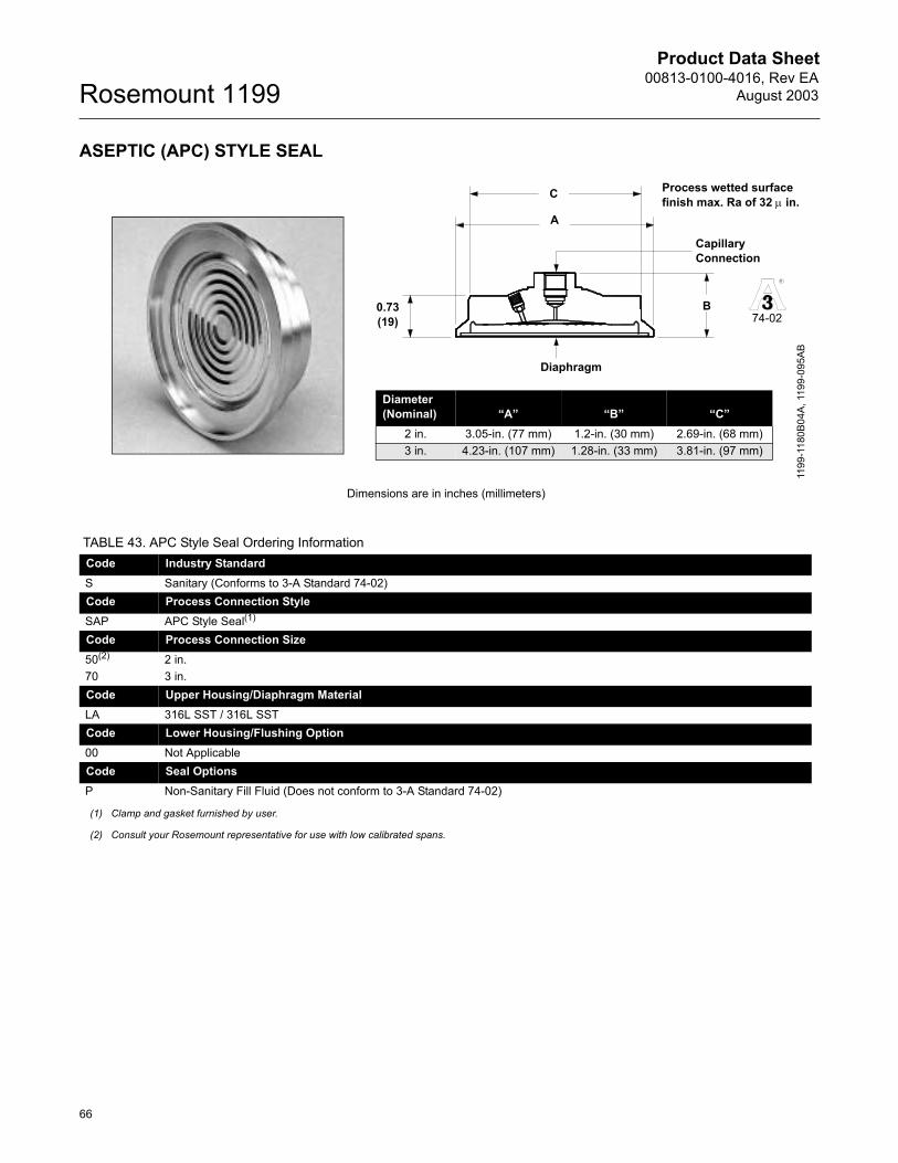
Product Data Sheet00813-0100-4016, Rev EA
August 2003Rosemount 1199
66
ASEPTIC (APC) STYLE SEAL
Dimensions are in inches (millimeters)
A
0.73 (19)
C
Diaphragm
Capillary Connection
B
Diameter (Nominal) �A� �B� �C�
2 in. 3.05-in. (77 mm) 1.2-in. (30 mm) 2.69-in. (68 mm)3 in. 4.23-in. (107 mm) 1.28-in. (33 mm) 3.81-in. (97 mm)
1199
-118
0B04
A, 1
199-
095A
B
R
37-0174-02
Process wetted surface finish max. Ra of 32 µ in.
TABLE 43. APC Style Seal Ordering InformationCode Industry StandardS Sanitary (Conforms to 3-A Standard 74-02)Code Process Connection StyleSAP APC Style Seal(1)
Code Process Connection Size50(2) 2 in.70 3 in.Code Upper Housing/Diaphragm MaterialLA 316L SST / 316L SSTCode Lower Housing/Flushing Option00 Not ApplicableCode Seal OptionsP Non-Sanitary Fill Fluid (Does not conform to 3-A Standard 74-02)
(1) Clamp and gasket furnished by user.
(2) Consult your Rosemount representative for use with low calibrated spans.
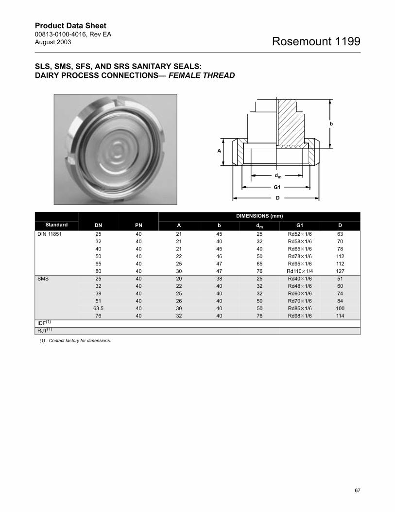
Product Data Sheet00813-0100-4016, Rev EAAugust 2003
67
Rosemount 1199
SLS, SMS, SFS, AND SRS SANITARY SEALS: DAIRY PROCESS CONNECTIONS� FEMALE THREAD
DN PN
DIMENSIONS (mm)Standard A b dm G1 D
DIN 11851 25 40 21 45 25 Rd52�1/6 6332 40 21 40 32 Rd58�1/6 7040 40 21 45 40 Rd65�1/6 7850 40 22 46 50 Rd78�1/6 11265 40 25 47 65 Rd95�1/6 11280 40 30 47 76 Rd110�1/4 127
SMS 25 40 20 38 25 Rd40�1/6 5132 40 22 40 32 Rd48�1/6 6038 40 25 40 32 Rd60�1/6 7451 40 26 40 50 Rd70�1/6 84
63.5 40 30 40 50 Rd85�1/6 10076 40 32 40 76 Rd98�1/6 114
IDF(1)
(1) Contact factory for dimensions.
RJT(1)
dm
G1
D
b
A
Product Data Sheet00813-0100-4016, Rev EA
August 2003Rosemount 1199
68
TABLE 44. SLS Sanitary Seals: Dairy Process Connection�Female Thread Ordering InformationCode Industry StandardS Sanitary Code Process Connection StyleSLS(1)(2) Female Thread per DIN 11851 Code Process Connection Size Maximum Working Pressure (Flange Rating)D0 DN 25 40 barF0 DN 40 40 barG0 DN 50 40 barJ0 DN 80 40 barE0 DN 32 40 barH0 DN 65 40 barCode Diaphragm Material Upper Housing MaterialLA00 316L SST 316L SST (coupling nut same material)WW00(1) 316Ti SST (WNr 1.4571) 316Ti SST (WNr 1.4571)Code Options (Multiple Selections)6 Electrolytical polishing of diaphragm material2 Counterpiece (tank/pipe spud) and Gasket
(1) Shaded areas indicate special orders. Consult your Rosemount representative for configuration availability, performance effects, and lead time.
(2) Available with welded capillary or direct mount connections only.
TABLE 45. SMS, SFS, and SRS Sanitary Seals: Dairy Process Connection�Female Thread Ordering InformationCode Industry StandardS Sanitary Code Process Connection StyleSMS(1)(2) Female Thread per SMS Standard SFS(2) Female Thread per IDF Standard SRS(2) Female Thread per RJT StandardCode Process Connection Size Maximum Working Pressure (Flange Rating)30 DN 38 (11/2 in.) 40 bar50 DN 51 (2 in.) 40 bar20 DN 25 40 bar60(3) DN 63.5 40 bar70 DN 76 40 barCode Diaphragm Material Housing MaterialLA00 316L SST 316L SST (coupling nut same material)LB00(4) Hastelloy C-276 316L SSTWW00(1) 316Ti SST (WNr 1.4571) 316Ti SST (WNr 1.4571)Code Options (Multiple Selections)6 Electrolytical polishing of diaphragm material2 Counterpiece (tank/pipe spud) and Gasket
(1) Shaded areas indicate special orders. Consult your Rosemount representative for configuration availability, performance effects, and lead time.
(2) Available with welded capillary or direct mount connections only.
(3) Process Connection Size Code 6 is not available with the SMS seal.
(4) Diaphragm/Housing Material code LB00 is available only with the SRS Seal.
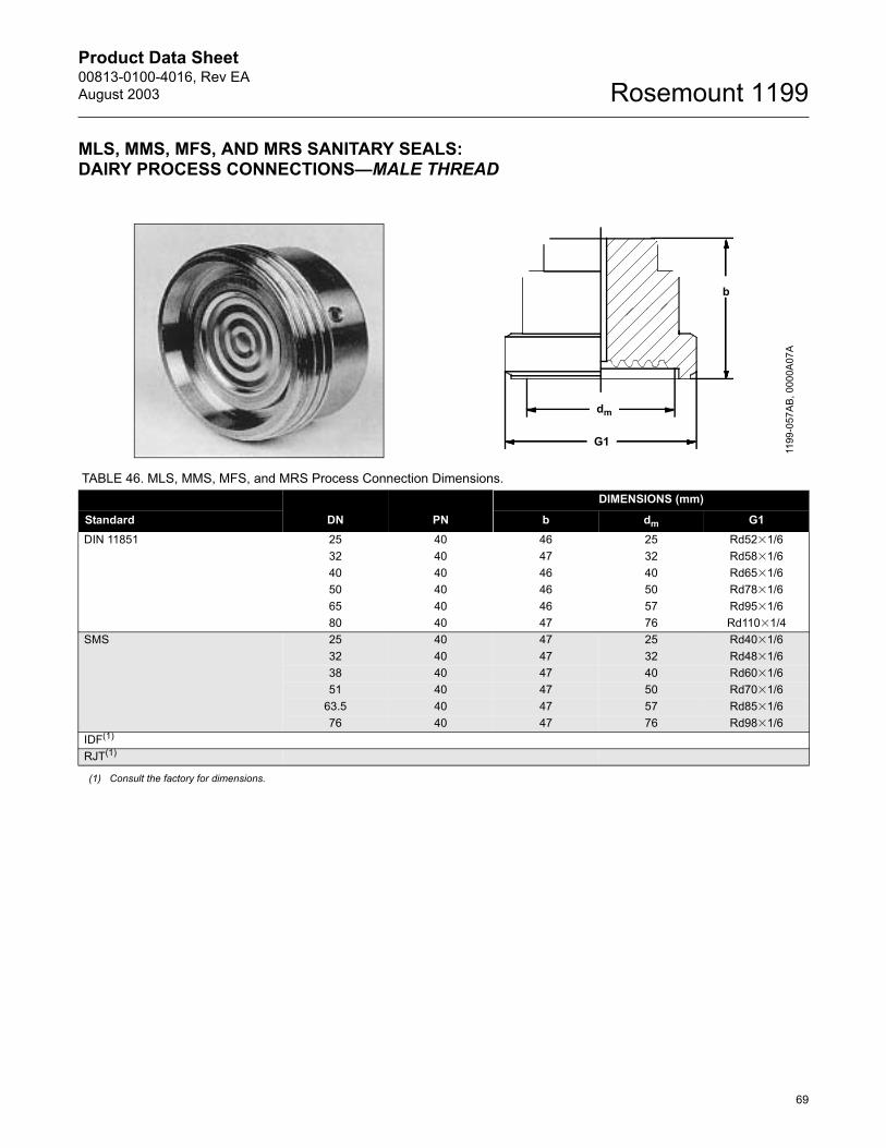
Product Data Sheet00813-0100-4016, Rev EAAugust 2003
69
Rosemount 1199
MLS, MMS, MFS, AND MRS SANITARY SEALS:DAIRY PROCESS CONNECTIONS�MALE THREAD
TABLE 46. MLS, MMS, MFS, and MRS Process Connection Dimensions.
DN PN
DIMENSIONS (mm)
Standard b dm G1DIN 11851 25 40 46 25 Rd52�1/6
32 40 47 32 Rd58�1/640 40 46 40 Rd65�1/650 40 46 50 Rd78�1/665 40 46 57 Rd95�1/680 40 47 76 Rd110�1/4
SMS 25 40 47 25 Rd40�1/632 40 47 32 Rd48�1/638 40 47 40 Rd60�1/651 40 47 50 Rd70�1/6
63.5 40 47 57 Rd85�1/676 40 47 76 Rd98�1/6
IDF(1)
RJT(1)
(1) Consult the factory for dimensions.
G1
dm
b
1199
-057
AB, 0
000A
07A
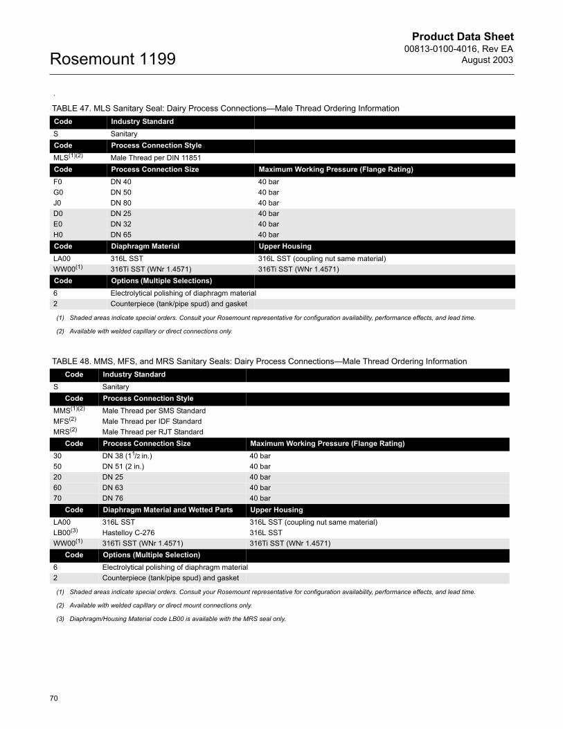
Product Data Sheet00813-0100-4016, Rev EA
August 2003Rosemount 1199
70
.
TABLE 47. MLS Sanitary Seal: Dairy Process Connections�Male Thread Ordering InformationCode Industry StandardS SanitaryCode Process Connection StyleMLS(1)(2) Male Thread per DIN 11851Code Process Connection Size Maximum Working Pressure (Flange Rating)F0 DN 40 40 barG0 DN 50 40 barJ0 DN 80 40 barD0 DN 25 40 barE0 DN 32 40 barH0 DN 65 40 barCode Diaphragm Material Upper HousingLA00 316L SST 316L SST (coupling nut same material)WW00(1) 316Ti SST (WNr 1.4571) 316Ti SST (WNr 1.4571)Code Options (Multiple Selections)6 Electrolytical polishing of diaphragm material2 Counterpiece (tank/pipe spud) and gasket
(1) Shaded areas indicate special orders. Consult your Rosemount representative for configuration availability, performance effects, and lead time.
(2) Available with welded capillary or direct connections only.
TABLE 48. MMS, MFS, and MRS Sanitary Seals: Dairy Process Connections�Male Thread Ordering InformationCode Industry Standard
S SanitaryCode Process Connection Style
MMS(1)(2) Male Thread per SMS StandardMFS(2) Male Thread per IDF StandardMRS(2) Male Thread per RJT Standard
Code Process Connection Size Maximum Working Pressure (Flange Rating)30 DN 38 (11/2 in.) 40 bar50 DN 51 (2 in.) 40 bar20 DN 25 40 bar60 DN 63 40 bar70 DN 76 40 bar
Code Diaphragm Material and Wetted Parts Upper HousingLA00 316L SST 316L SST (coupling nut same material)LB00(3) Hastelloy C-276 316L SSTWW00(1) 316Ti SST (WNr 1.4571) 316Ti SST (WNr 1.4571)
Code Options (Multiple Selection)6 Electrolytical polishing of diaphragm material2 Counterpiece (tank/pipe spud) and gasket
(1) Shaded areas indicate special orders. Consult your Rosemount representative for configuration availability, performance effects, and lead time.
(2) Available with welded capillary or direct mount connections only.
(3) Diaphragm/Housing Material code LB00 is available with the MRS seal only.
Product Data Sheet00813-0100-4016, Rev EAAugust 2003
71
Rosemount 1199
General Information
This product data sheet provides information on Rosemount transmitter/diaphragm seal systems.
Rosemount 1199 diaphragm seals can be assembled to Rosemount 3051, 1151, and 2088 differential, gage, and absolute pressure transmitters, and liquid level transmitters. For additional information, refer to the following product data sheets:
� Rosemount 3051S Series (document number 00813-0100-4801)
� Rosemount 3051 Pressure Transmitter(document number 00813-0100-4001)
� Rosemount 1151 Analog Pressure Transmitters(document number 00813-0100-4360)
� Rosemount 2088 Gage and Absolute Pressure Transmitter (document number 00813-0100-4690)
� Rosemount 1199 SOAP 2000 Software(document number 00813-0100-4017)
NOTEMany other special-order transmitter/diaphragm seal materials, configurations, and fill fluids are available that are not covered in this document. Contact your Rosemount representative or consult the factory for additional information.
WHAT IS A DIAPHRAGM SEAL SYSTEM?A diaphragm seal system consists of a pressure transmitter, a diaphragm seal, a fill fluid, and either a direct mount or capillary style connection.
During operation, the thin, flexible diaphragm and fill fluid separate the pressure sensitive element of the transmitter from the process medium. The capillary tubing or direct mount flange connects the diaphragm to the transmitter.
When process pressure is applied, the diaphragm is displaced, transferring the measured pressure through the filled system, through the capillary tubing, to the transmitter element. This transferred pressure displaces the sensing diaphragm in the pressure-sensitive element of the transmitter. This displacement is proportional to the process pressure and is converted electronically to an appropriate current, voltage, or digital HART (Highway Addressable Remote Transducer) output signal.
WHY USE DIAPHRAGM SEALS?Seal systems provide a reliable process pressure measurement and prevent the process medium from contacting the transmitter diaphragm.
Transmitter/diaphragm seal systems should be considered when:
� The process temperature is outside of the normal operating ranges of the transmitter and cannot be brought into those limits with impulse piping.
� The process is corrosive and would require frequent transmitter replacement or unusual materials of construction.
� The process contains suspended solids or is viscous and may plug the impulse piping.
� The application requires the use of sanitary connections.
� There is a need for easier cleaning of the process from the connections to avoid contamination between batches.
� There is a need to replace wet legs to reduce maintenance on applications where the wet leg is not stable or often needs to be refilled.
� There is a need to make density or interface measurements.
� The process medium may freeze or solidify in the transmitter or impulse piping.
Product Data Sheet00813-0100-4016, Rev EA
August 2003Rosemount 1199
72
PERFORMANCE CONSIDERATIONS
Temperature EffectsTemperature effects occur when the fill fluid expands or contracts with fluctuations in the process or ambient temperature. This change in fill volume drives a change in the internal pressure of the transmitter/seal system.
Two primary factors affect the temperature performance of a diaphragm seal system: the diaphragm stiffness and the characteristics of the fill fluid.
Diaphragm Stiffness
Diaphragm stiffness is a critical parameter affecting temperature performance. As the fill fluid expands and contracts due to temperature changes, a flexible diaphragm will exert less back pressure than a stiff diaphragm (for equal changes in fill volume). Back pressure causes a measurement error as it acts upon the sensing diaphragm of the transmitter. Therefore, the more flexible diaphragm seal can accommodate changes in fill volume and minimize errors resulting from temperature changes.
Diaphragm stiffness is affected by the diaphragm surface diameter, material of construction, thickness, and convolution pattern. Of these factors, the most significant is the diaphragm seal diameter. Each diaphragm has its own characteristic stiffness curve. Generally, smaller diameter diaphragms are stiffer than larger diameter diaphragms, and thus have stiffness curves that are less vertical. A more vertical stiffness curve helps to minimize the amount of pressure error that can occur when the fill fluid expands or contracts with temperature changes.
Figure 1 on page 73 shows that large-diameter diaphragms, which are less stiff, have smaller errors caused by changes in the fill fluid volume. This is the result of a more vertical stiffness curve. The small-diameter diaphragms have a less vertical stiffness curve, resulting in larger errors with changes in temperature.
Fill Fluid
The expansion characteristics and the volume of the fill fluid affect seal performance.
All fill fluids expand and contract with changes in temperature. The coefficient of thermal expansion defines the amount of change and is represented in cubic centimeters of expansion per cubic centimeter of fluid per degree Fahrenheit (cc/cc/F). The amount of expansion varies between fill fluids, as shown in Figure 1, graph 2. Selecting a fill fluid with a smaller coefficient of thermal expansion will help minimize temperature error. Table 1, �Fill Fluid Specifications� on page 3, provides the coefficients of thermal expansion for all available fill fluids.
A larger volume of fill fluid increases the potential for volume expansion. By minimizing the capillary length and inside diameter, fill volumes can be kept as low as possible to reduce temperature effects.
Head Effects
Head effect is a result of a change in the density of the fill fluid in the capillaries. This effect is caused by fluctuations in the process or ambient temperature, and can be additive to temperature effect errors.
Head effects are dependent on the change in ambient temperature, capillary inside diameter and fill fluid, and the distance between process connection taps (not the capillary length).
Consult the SOAP 2000 program or your Rosemount Inc. representative for more information on temperature or head effects.
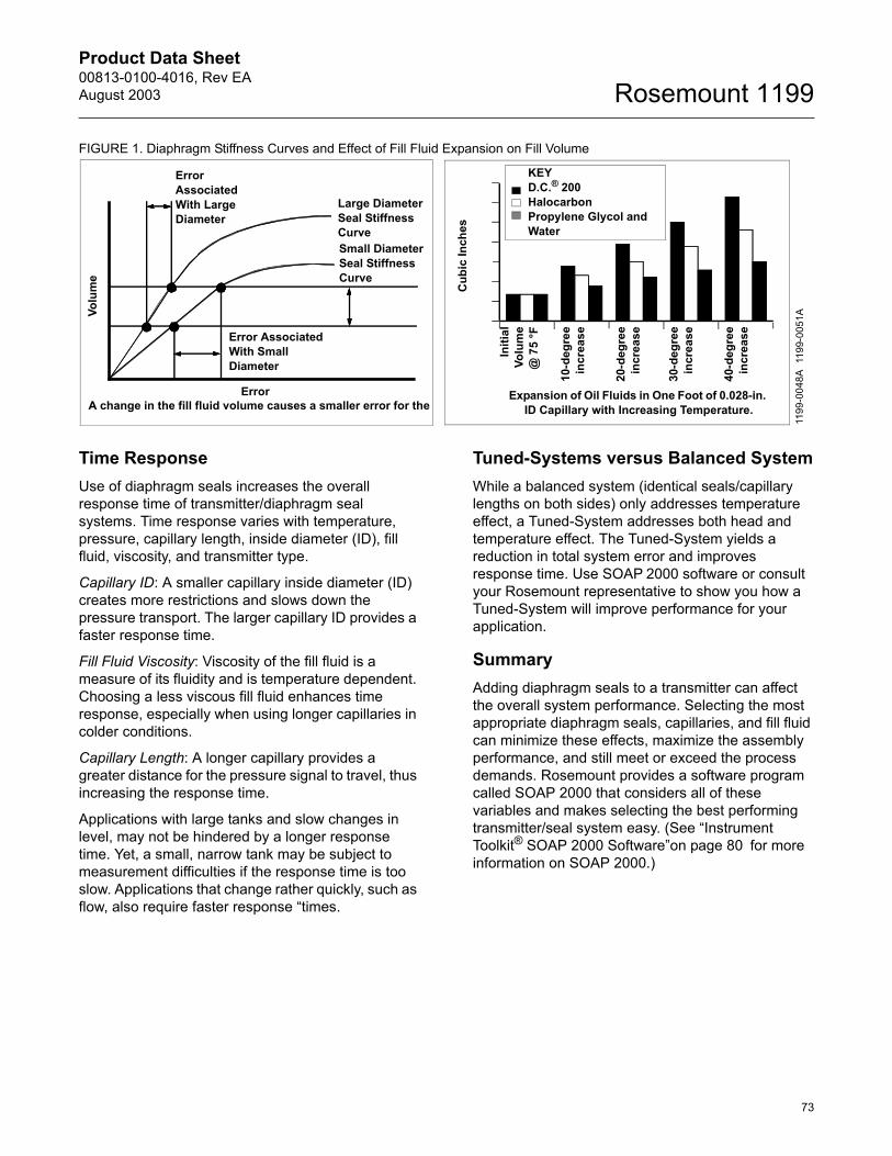
Product Data Sheet00813-0100-4016, Rev EAAugust 2003
73
Rosemount 1199
FIGURE 1. Diaphragm Stiffness Curves and Effect of Fill Fluid Expansion on Fill Volume
Time ResponseUse of diaphragm seals increases the overall response time of transmitter/diaphragm seal systems. Time response varies with temperature, pressure, capillary length, inside diameter (ID), fill fluid, viscosity, and transmitter type.
Capillary ID: A smaller capillary inside diameter (ID) creates more restrictions and slows down the pressure transport. The larger capillary ID provides a faster response time.
Fill Fluid Viscosity: Viscosity of the fill fluid is a measure of its fluidity and is temperature dependent. Choosing a less viscous fill fluid enhances time response, especially when using longer capillaries in colder conditions.
Capillary Length: A longer capillary provides a greater distance for the pressure signal to travel, thus increasing the response time.
Applications with large tanks and slow changes in level, may not be hindered by a longer response time. Yet, a small, narrow tank may be subject to measurement difficulties if the response time is too slow. Applications that change rather quickly, such as flow, also require faster response �times.
Tuned-Systems versus Balanced SystemWhile a balanced system (identical seals/capillary lengths on both sides) only addresses temperature effect, a Tuned-System addresses both head and temperature effect. The Tuned-System yields a reduction in total system error and improves response time. Use SOAP 2000 software or consult your Rosemount representative to show you how a Tuned-System will improve performance for your application.
SummaryAdding diaphragm seals to a transmitter can affect the overall system performance. Selecting the most appropriate diaphragm seals, capillaries, and fill fluid can minimize these effects, maximize the assembly performance, and still meet or exceed the process demands. Rosemount provides a software program called SOAP 2000 that considers all of these variables and makes selecting the best performing transmitter/seal system easy. (See �Instrument Toolkit® SOAP 2000 Software�on page 80 for more information on SOAP 2000.)
1199
-005
1A
Cub
ic In
ches
Initi
alVo
l um
e@
75
°F
10-d
egre
ein
crea
se
20- d
egre
ein
c rea
s e
3 0-d
egre
ein
cre a
se
40- d
egr e
ein
c rea
s e
Expansion of Oil Fluids in One Foot of 0.028-in. ID Capillary with Increasing Temperature.
KEYD.C.® 200HalocarbonPropylene Glycol and Water
Error AssociatedWith LargeDiameter
Large Diameter Seal Stiffness CurveSmall Diameter Seal Stiffness Curve
Error AssociatedWith SmallDiameter
Error
Volu
me
1199
-004
8A
A change in the fill fluid volume causes a smaller error for the
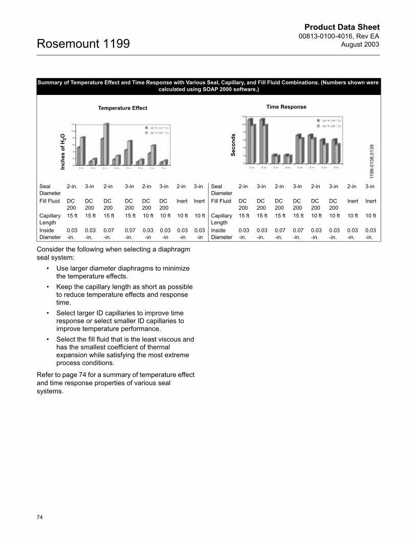
Product Data Sheet00813-0100-4016, Rev EA
August 2003Rosemount 1199
74
Consider the following when selecting a diaphragm seal system:
� Use larger diameter diaphragms to minimize the temperature effects.
� Keep the capillary length as short as possible to reduce temperature effects and response time.
� Select larger ID capillaries to improve time response or select smaller ID capillaries to improve temperature performance.
� Select the fill fluid that is the least viscous and has the smallest coefficient of thermal expansion while satisfying the most extreme process conditions.
Refer to page 74 for a summary of temperature effect and time response properties of various seal systems.
Summary of Temperature Effect and Time Response with Various Seal, Capillary, and Fill Fluid Combinations. (Numbers shown were calculated using SOAP 2000 software.)
Seal Diameter
2-in. 3-in 2-in 3-in 2-in 3-in 2-in 3-in Seal Diameter
2-in 3-in 2-in 3-in 2-in 3-in 2-in 3-in
Fill Fluid DC200
DC200
DC200
DC200
DC200
DC200
Inert Inert Fill Fluid DC200
DC200
DC200
DC200
DC200
DC200
Inert Inert
CapillaryLength
15 ft 15 ft 15 ft 15 ft 10 ft 10 ft 10 ft 10 ft CapillaryLength
15 ft 15 ft 15 ft 15 ft 10 ft 10 ft 10 ft 10 ft
Inside Diameter
0.03-in.
0.03-in.
0.07-in.
0.07-in.
0.03-in
0.03-in
0.03-in
0.03-in
Inside Diameter
0.03-in.
0.03-in.
0.07-in.
0.07-in.
0.03-in.
0.03-in.
0.03-in.
0.03-in.
Temperature Effect
Inch
es o
f H2O
Time Response
Seco
nds
1199
-013
8,01
39
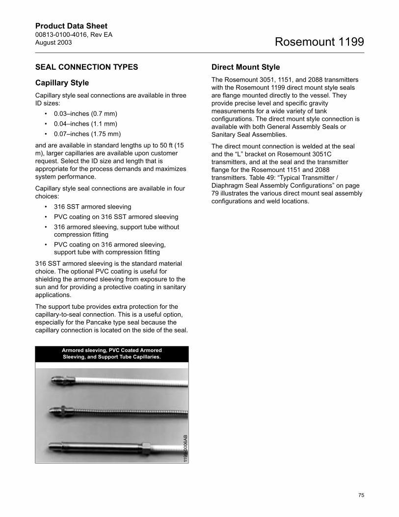
Product Data Sheet00813-0100-4016, Rev EAAugust 2003
75
Rosemount 1199
SEAL CONNECTION TYPES
Capillary StyleCapillary style seal connections are available in three ID sizes:
� 0.03�inches (0.7 mm)� 0.04�inches (1.1 mm)� 0.07�inches (1.75 mm)
and are available in standard lengths up to 50 ft (15 m), larger capillaries are available upon customer request. Select the ID size and length that is appropriate for the process demands and maximizes system performance.
Capillary style seal connections are available in four choices:
� 316 SST armored sleeving� PVC coating on 316 SST armored sleeving � 316 armored sleeving, support tube without
compression fitting� PVC coating on 316 armored sleeving,
support tube with compression fitting
316 SST armored sleeving is the standard material choice. The optional PVC coating is useful for shielding the armored sleeving from exposure to the sun and for providing a protective coating in sanitary applications.
The support tube provides extra protection for the capillary-to-seal connection. This is a useful option, especially for the Pancake type seal because the capillary connection is located on the side of the seal.
Direct Mount StyleThe Rosemount 3051, 1151, and 2088 transmitters with the Rosemount 1199 direct mount style seals are flange mounted directly to the vessel. They provide precise level and specific gravity measurements for a wide variety of tank configurations. The direct mount style connection is available with both General Assembly Seals or Sanitary Seal Assemblies.
The direct mount connection is welded at the seal and the �L� bracket on Rosemount 3051C transmitters, and at the seal and the transmitter flange for the Rosemount 1151 and 2088 transmitters. Table 49: �Typical Transmitter / Diaphragm Seal Assembly Configurations� on page 79 illustrates the various direct mount seal assembly configurations and weld locations.
Armored sleeving, PVC Coated Armored Sleeving, and Support Tube Capillaries.
1199
-000
6AB
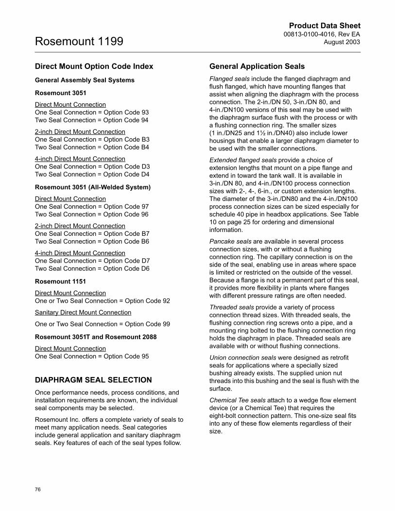
Product Data Sheet00813-0100-4016, Rev EA
August 2003Rosemount 1199
76
Direct Mount Option Code IndexGeneral Assembly Seal Systems
Rosemount 3051
Direct Mount ConnectionOne Seal Connection = Option Code 93Two Seal Connection = Option Code 94
2-inch Direct Mount ConnectionOne Seal Connection = Option Code B3Two Seal Connection = Option Code B4
4-inch Direct Mount ConnectionOne Seal Connection = Option Code D3Two Seal Connection = Option Code D4
Rosemount 3051 (All-Welded System)
Direct Mount ConnectionOne Seal Connection = Option Code 97Two Seal Connection = Option Code 96
2-inch Direct Mount ConnectionOne Seal Connection = Option Code B7Two Seal Connection = Option Code B6
4-inch Direct Mount ConnectionOne Seal Connection = Option Code D7Two Seal Connection = Option Code D6
Rosemount 1151
Direct Mount ConnectionOne or Two Seal Connection = Option Code 92
Sanitary Direct Mount Connection
One or Two Seal Connection = Option Code 99
Rosemount 3051T and Rosemount 2088
Direct Mount ConnectionOne Seal Connection = Option Code 95
DIAPHRAGM SEAL SELECTION Once performance needs, process conditions, and installation requirements are known, the individual seal components may be selected.
Rosemount Inc. offers a complete variety of seals to meet many application needs. Seal categories include general application and sanitary diaphragm seals. Key features of each of the seal types follow.
General Application SealsFlanged seals include the flanged diaphragm and flush flanged, which have mounting flanges that assist when aligning the diaphragm with the process connection. The 2-in./DN 50, 3-in./DN 80, and 4-in./DN100 versions of this seal may be used with the diaphragm surface flush with the process or with a flushing connection ring. The smaller sizes(1 in./DN25 and 1½ in./DN40) also include lower housings that enable a larger diaphragm diameter to be used with the smaller connections.
Extended flanged seals provide a choice of extension lengths that mount on a pipe flange and extend in toward the tank wall. It is available in 3-in./DN 80, and 4-in./DN100 process connection sizes with 2-, 4-, 6-in., or custom extension lengths. The diameter of the 3-in./DN80 and the 4-in./DN100 process connection sizes can be sized especially for schedule 40 pipe in headbox applications. See Table 10 on page 25 for ordering and dimensional information.
Pancake seals are available in several process connection sizes, with or without a flushing connection ring. The capillary connection is on the side of the seal, enabling use in areas where space is limited or restricted on the outside of the vessel. Because a flange is not a permanent part of this seal, it provides more flexibility in plants where flanges with different pressure ratings are often needed.
Threaded seals provide a variety of process connection thread sizes. With threaded seals, the flushing connection ring screws onto a pipe, and a mounting ring bolted to the flushing connection ring holds the diaphragm in place. Threaded seals are available with or without flushing connections.
Union connection seals were designed as retrofit seals for applications where a specially sized bushing already exists. The supplied union nut threads into this bushing and the seal is flush with the surface.
Chemical Tee seals attach to a wedge flow element device (or a Chemical Tee) that requires the eight-bolt connection pattern. This one-size seal fits into any of these flow elements regardless of their size.
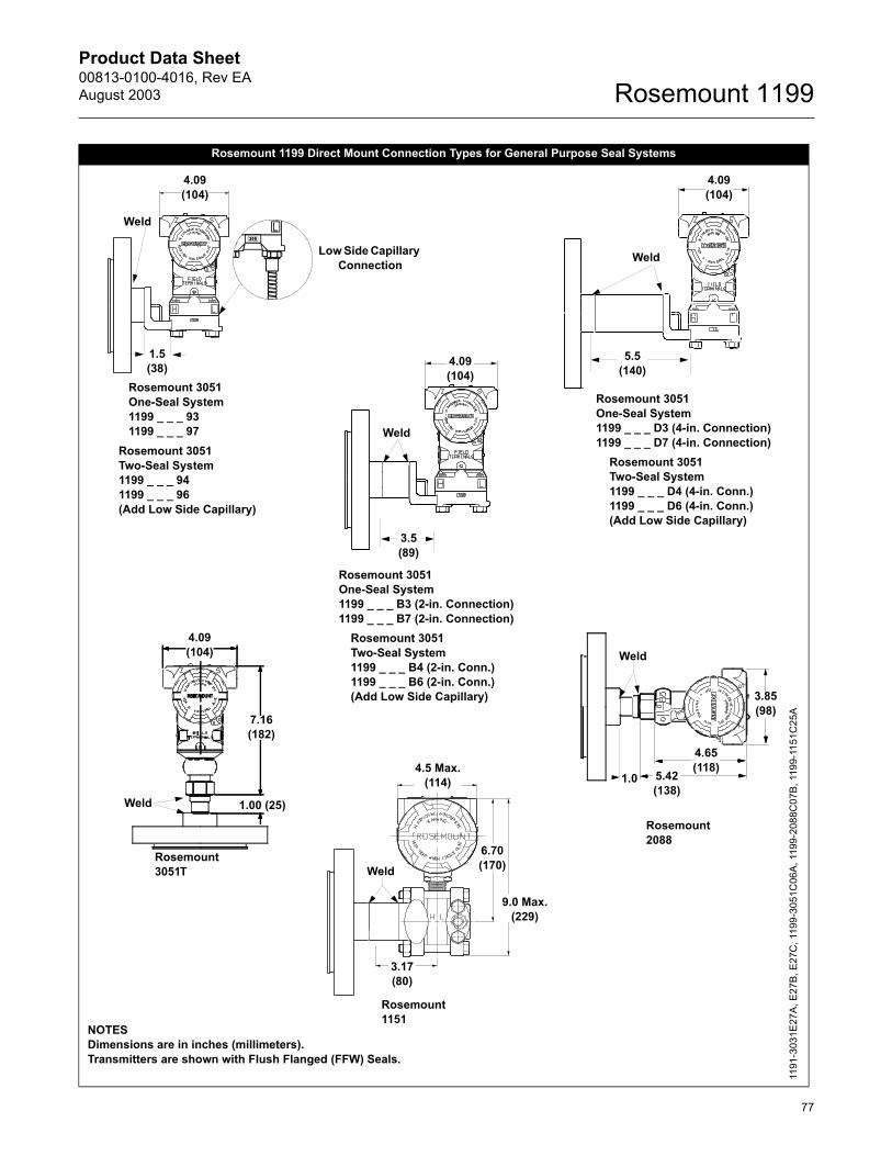
Product Data Sheet00813-0100-4016, Rev EAAugust 2003
77
Rosemount 1199
Rosemount 1199 Direct Mount Connection Types for General Purpose Seal Systems
Weld
4.09(104)
3.5(89)
Rosemount 3051Two-Seal System1199 _ _ _ 94 1199 _ _ _ 96(Add Low Side Capillary)
Rosemount 1151
Rosemount 2088
Rosemount 3051One-Seal System1199 _ _ _ 93 1199 _ _ _ 97
Weld
4.09(104)
Rosemount 3051T
4.09(104)
7.16(182)
1.00 (25)
3.17(80)
6.70(170)
9.0 Max.(229)
4.5 Max.(114)
3.85(98)
4.65(118)
5.42(138)
Rosemount 3051One-Seal System1199 _ _ _ D3 (4-in. Connection)1199 _ _ _ D7 (4-in. Connection)
Rosemount 3051Two-Seal System1199 _ _ _ D4 (4-in. Conn.)1199 _ _ _ D6 (4-in. Conn.)(Add Low Side Capillary)
Rosemount 3051One-Seal System1199 _ _ _ B3 (2-in. Connection)1199 _ _ _ B7 (2-in. Connection)
Rosemount 3051Two-Seal System1199 _ _ _ B4 (2-in. Conn.)1199 _ _ _ B6 (2-in. Conn.)(Add Low Side Capillary)
4.09(104)
5.5(140)
1.5(38)
Weld
Weld
Weld
1.0
Weld
Low Side Capillary Connection
NOTESDimensions are in inches (millimeters). Transmitters are shown with Flush Flanged (FFW) Seals.
1191
-303
1E27
A, E
27B,
E27
C, 1
199-
3051
C06
A, 1
199-
2088
C07
B, 1
199-
1151
C25
A
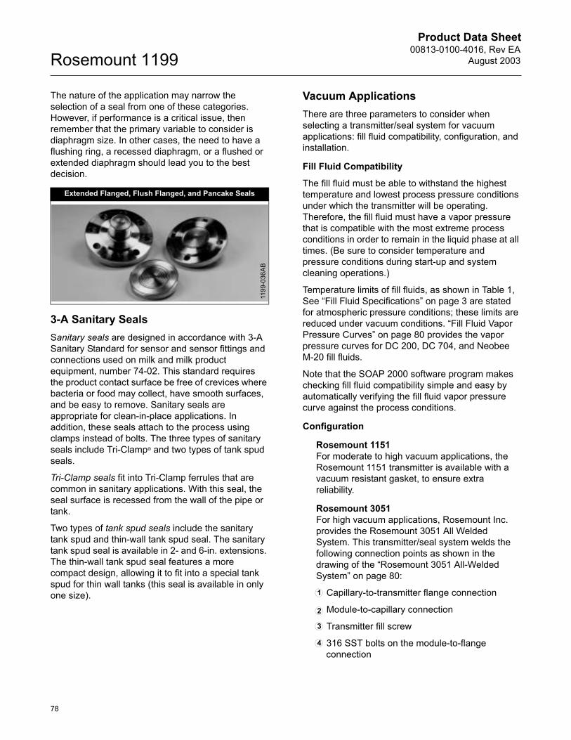
Product Data Sheet00813-0100-4016, Rev EA
August 2003Rosemount 1199
78
The nature of the application may narrow the selection of a seal from one of these categories. However, if performance is a critical issue, then remember that the primary variable to consider is diaphragm size. In other cases, the need to have a flushing ring, a recessed diaphragm, or a flushed or extended diaphragm should lead you to the best decision.
3-A Sanitary SealsSanitary seals are designed in accordance with 3-A Sanitary Standard for sensor and sensor fittings and connections used on milk and milk product equipment, number 74-02. This standard requires the product contact surface be free of crevices where bacteria or food may collect, have smooth surfaces, and be easy to remove. Sanitary seals are appropriate for clean-in-place applications. In addition, these seals attach to the process using clamps instead of bolts. The three types of sanitary seals include Tri-Clamp® and two types of tank spud seals.
Tri-Clamp seals fit into Tri-Clamp ferrules that are common in sanitary applications. With this seal, the seal surface is recessed from the wall of the pipe or tank.
Two types of tank spud seals include the sanitary tank spud and thin-wall tank spud seal. The sanitary tank spud seal is available in 2- and 6-in. extensions. The thin-wall tank spud seal features a more compact design, allowing it to fit into a special tank spud for thin wall tanks (this seal is available in only one size).
Vacuum ApplicationsThere are three parameters to consider when selecting a transmitter/seal system for vacuum applications: fill fluid compatibility, configuration, and installation.
Fill Fluid Compatibility
The fill fluid must be able to withstand the highest temperature and lowest process pressure conditions under which the transmitter will be operating. Therefore, the fill fluid must have a vapor pressure that is compatible with the most extreme process conditions in order to remain in the liquid phase at all times. (Be sure to consider temperature and pressure conditions during start-up and system cleaning operations.)
Temperature limits of fill fluids, as shown in Table 1, See �Fill Fluid Specifications� on page 3 are stated for atmospheric pressure conditions; these limits are reduced under vacuum conditions. �Fill Fluid Vapor Pressure Curves� on page 80 provides the vapor pressure curves for DC 200, DC 704, and Neobee M-20 fill fluids.
Note that the SOAP 2000 software program makes checking fill fluid compatibility simple and easy by automatically verifying the fill fluid vapor pressure curve against the process conditions.
Configuration
Rosemount 1151For moderate to high vacuum applications, the Rosemount 1151 transmitter is available with a vacuum resistant gasket, to ensure extra reliability.
Rosemount 3051For high vacuum applications, Rosemount Inc. provides the Rosemount 3051 All Welded System. This transmitter/seal system welds the following connection points as shown in the drawing of the �Rosemount 3051 All-Welded System� on page 80:
Capillary-to-transmitter flange connection
Module-to-capillary connection
Transmitter fill screw
316 SST bolts on the module-to-flange connection
Extended Flanged, Flush Flanged, and Pancake Seals
1199
-036
AB
2
3
4
1

Product Data Sheet00813-0100-4016, Rev EAAugust 2003
79
Rosemount 1199
The welded connections that are not shown in the drawing of the �Rosemount 3051 All-Welded System� on page 80, include the seal fill screw and the capillary-to-seal connection.
The key difference between the Rosemount 3051 AWS and the Rosemount 3051, with welded capillaries, is the welded module-to-capillary connection.
To order the Rosemount 3051 All Welded System, specify S7, S8, S9, or S0 for the 3051 diaphragm seal code.
TABLE 49. Typical Transmitter / Diaphragm Seal Assembly Configurations
Rosemount 1151 Differential with Rosemount 1199 Pancake Diaphragm Seal Two Seal System
Rosemount 3051C Differential with Rosemount 1199 Threaded Remote Seal One-Seal System
Rosemount 3051S Gage with Rosemount 1199 Flush Flanged Diaphragm Seal One-Seal System
Rosemount 2088 with Rosemount 1199 Flanged Diaphragm Seal One-Seal System
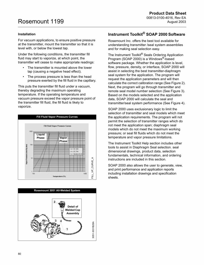
Product Data Sheet00813-0100-4016, Rev EA
August 2003Rosemount 1199
80
Installation
For vacuum applications, to ensure positive pressure at the transmitter, mount the transmitter so that it is level with, or below the lowest tap.
Under the following conditions, the transmitter fill fluid may start to vaporize, at which point, the transmitter will cease to make appropriate readings:
� The transmitter is mounted above the lower tap (causing a negative head effect).
� The process pressure is less than the head pressure exerted by the fill fluid in the capillary.
This puts the transmitter fill fluid under a vacuum, thereby degrading the maximum operating temperature. If the operating temperature and vacuum pressure exceed the vapor pressure point of the transmitter fill fluid, the fill fluid is likely to vaporize.
Instrument Toolkit® SOAP 2000 Software Rosemount Inc. offers the best tool available for understanding transmitter /seal system assemblies and for making seal selection easy.
The Instrument Toolkit® Seals Ordering Application Program (SOAP 2000) is a Windows®-based software package. Whether the application is level, flow, pressure, density, or interface, SOAP 2000 will assist in selecting the best transmitter-diaphragm seal system for the application. The program will request the application parameters and will then calculate the correct calibration range (See Figure 2). Next, the program will go through transmitter and remote seal model number selection (See Figure 3). Based on the models selected and the application data, SOAP 2000 will calculate the seal and transmitter/seal system performance (See Figure 4).
SOAP 2000 uses exclusionary logic to limit the selection of transmitter and seal models which meet the application requirements. The program will not permit the selection of transmitter ranges which do not meet the application span; diaphragm seal models which do not meet the maximum working pressure; or seal fill fluids which do not meet the temperature and vapor pressure limitations.
The Instrument Toolkit Help section includes other tools to assist in Diaphragm Seal selection. seal dimensional drawings, product data, selection fundamentals, technical information, and ordering instructions are included in this section.
SOAP 2000 also allows the user to generate, view, and print performance and application reports including installation drawings and specification sheets.
Fill Fluid Vapor Pressure Curves
Rosemount 3051 All-Welded System
LiquidPhase Vapor
Phase
FILL
_VP_
CU
RVE
_A
1
43
Detail of Welded Cap Assembly
3051
-303
1B28
A
2
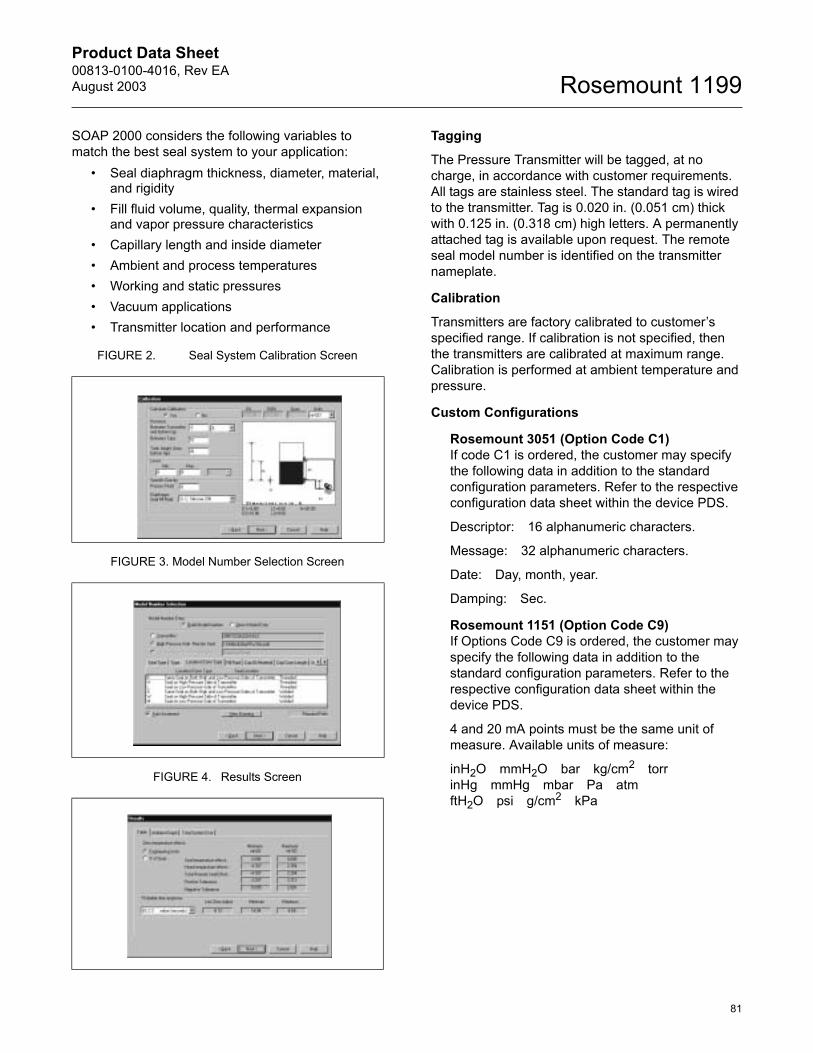
Product Data Sheet00813-0100-4016, Rev EAAugust 2003
81
Rosemount 1199
SOAP 2000 considers the following variables to match the best seal system to your application:
� Seal diaphragm thickness, diameter, material, and rigidity
� Fill fluid volume, quality, thermal expansion and vapor pressure characteristics
� Capillary length and inside diameter� Ambient and process temperatures� Working and static pressures� Vacuum applications� Transmitter location and performance
FIGURE 2. Seal System Calibration Screen
FIGURE 3. Model Number Selection Screen
FIGURE 4. Results Screen
Tagging
The Pressure Transmitter will be tagged, at no charge, in accordance with customer requirements. All tags are stainless steel. The standard tag is wired to the transmitter. Tag is 0.020 in. (0.051 cm) thick with 0.125 in. (0.318 cm) high letters. A permanently attached tag is available upon request. The remote seal model number is identified on the transmitter nameplate.
Calibration
Transmitters are factory calibrated to customer�s specified range. If calibration is not specified, then the transmitters are calibrated at maximum range. Calibration is performed at ambient temperature and pressure.
Custom Configurations
Rosemount 3051 (Option Code C1) If code C1 is ordered, the customer may specify the following data in addition to the standard configuration parameters. Refer to the respective configuration data sheet within the device PDS.
Descriptor: 16 alphanumeric characters.
Message: 32 alphanumeric characters.
Date: Day, month, year.
Damping: Sec.
Rosemount 1151 (Option Code C9) If Options Code C9 is ordered, the customer may specify the following data in addition to the standard configuration parameters. Refer to the respective configuration data sheet within the device PDS.
4 and 20 mA points must be the same unit of measure. Available units of measure:
inH2O mmH2O bar kg/cm2 torrinHg mmHg mbar Pa atmftH2O psi g/cm2 kPa
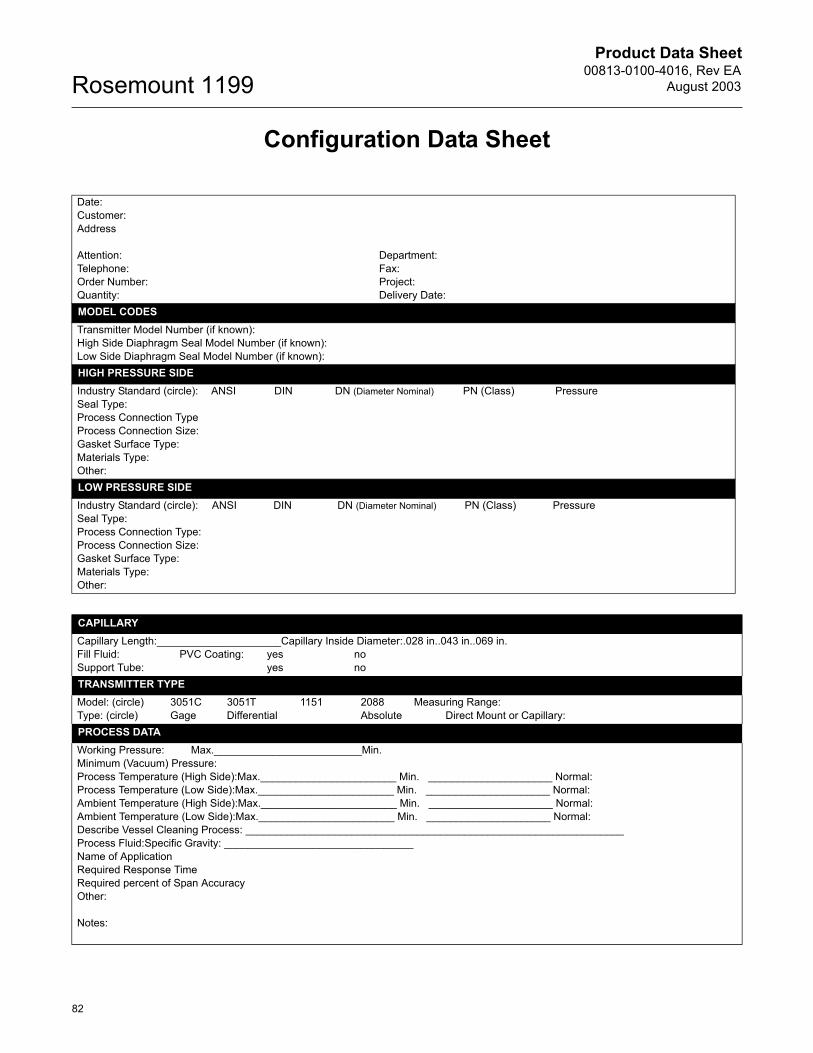
Product Data Sheet00813-0100-4016, Rev EA
August 2003Rosemount 1199
82
Configuration Data Sheet
Date:Customer:Address
Attention: Department:Telephone: Fax:Order Number: Project:Quantity: Delivery Date:MODEL CODESTransmitter Model Number (if known):High Side Diaphragm Seal Model Number (if known):Low Side Diaphragm Seal Model Number (if known):HIGH PRESSURE SIDEIndustry Standard (circle): ANSI DIN DN (Diameter Nominal) PN (Class) PressureSeal Type:Process Connection TypeProcess Connection Size:Gasket Surface Type:Materials Type:Other:LOW PRESSURE SIDEIndustry Standard (circle): ANSI DIN DN (Diameter Nominal) PN (Class) PressureSeal Type:Process Connection Type:Process Connection Size:Gasket Surface Type:Materials Type:Other:
CAPILLARYCapillary Length:_____________________Capillary Inside Diameter:.028 in..043 in..069 in.Fill Fluid: PVC Coating: yes noSupport Tube: yes noTRANSMITTER TYPEModel: (circle) 3051C 3051T 1151 2088 Measuring Range:Type: (circle) Gage Differential Absolute Direct Mount or Capillary:PROCESS DATAWorking Pressure: Max._________________________Min.Minimum (Vacuum) Pressure:Process Temperature (High Side):Max._______________________ Min. _____________________ Normal:Process Temperature (Low Side):Max._______________________ Min. _____________________ Normal:Ambient Temperature (High Side):Max._______________________ Min. _____________________ Normal: Ambient Temperature (Low Side):Max._______________________ Min. _____________________ Normal: Describe Vessel Cleaning Process: ________________________________________________________________Process Fluid:Specific Gravity: ________________________________Name of Application Required Response TimeRequired percent of Span AccuracyOther:
Notes:
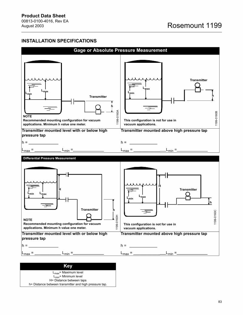
Product Data Sheet00813-0100-4016, Rev EAAugust 2003
83
Rosemount 1199
INSTALLATION SPECIFICATIONS
Gage or Absolute Pressure Measurement
Transmitter mounted level with or below high pressure tap
h =
Lmax = ____________ Lmin =
Transmitter mounted above high pressure tap
h =
Lmax = ____________ Lmin =
Differential Pressure Measurement
Transmitter mounted level with or below high pressure tap
h =
Lmax = ____________ Lmin =
Transmitter mounted above high pressure tap
h =
Lmax = ____________ Lmin =
h
LmaxLminTransmitter
NOTERecommended mounting configuration for vacuum applications. Minimum h value one meter. 11
99-0
160A
Transmitter
h
LmaxLmin
This configuration is not for use in vacuum applications. 11
99-0
160B
Transmitter h
HLmaxLmin
NOTERecommended mounting configuration for vacuum applications. Minimum h value one meter. 11
99-0
160H
Transmitter
h
H
LmaxLmin
This configuration is not for use invacuum applications.
1199
-016
0C
KeyLmax= Maximum levelLmin= Minimum level
H= Distance between tapsh= Distance between transmitter and high pressure tap.
Product Data Sheet00813-0100-4016, Rev EAAugust 2003 Rosemount 1199
Emerson Process Management
© 2003 Rosemount Inc. All rights reserved.
¢00813-0100-4016-¤
Rosemount and the Rosemount logotype are registerd trademarks of Rosemount Inc.Coplanar, SOAP 2000 and Tuned-Systems are trademarks of Rosemount Inc.PlantWeb is a mark of one of the Emerson Process Management companies.Inconel and Monel are registered trademarks of the International Nickel Co. Viton and Teflon are registered trademarks of E.I. duPont de Nemours & Co.Hastelloy, Hastelloy C, and Hastelloy C-276 are registered trademarks of Cabot Corp.Syltherm, and D.C. are regiastered trademarks of Dow Corning Corp.Tri-Clamp is a registered trademark of Tri-Clover, Inc. of the Alfa-Laval Group.Thermo-Tork is a registered trademark of Armstron World Industries, Inc. Neobee M-20 is a registered trademark of Stepan Chemical Co. Windows is a registered trademark of Microsoft Corp.Cherry-Burrell is a trademark of the United Dominion Industries.The 3-A symbol is a registered trademark of the 3-A Sanitary Standards Symbol Council.
Many other special order transmitter/seal configurations, materials and fill fluids are available that are not covered in this document. Contact your Rosemount representative or consult factory for additional information.
Rosemount Inc.8200 Market BoulevardChanhassen, MN 55317 USAT (U.S) 1-800-999-9307T (International) (952) 906-8888F (952) 949-7001
www.rosemount.com
Emerson Process Management GmbH & Co. OHGArgelsrieder Feld 382234 WesslingGermanyT 49 (8153) 9390F49 (8153) 939172
Emerson Process Management Asia Pacific Private Limited1 Pandan CrescentSingapore 128461T (65) 6777 8211F (65) 6777 0947/65 6777 0743