Room-Temperature Synthesis of Transition Metal … · Room-Temperature Synthesis of Transition...
115
Room-Temperature Synthesis of Transition Metal Clusters and Main Group Polycations from Ionic Liquids D I S S E R T A T I O N zur Erlangung des akademischen Grades Doctor rerum naturalium (Dr. rer. nat.) vorgelegt der Fakultät Mathematik und Naturwissenschaften der Technischen Universität Dresden von M. Phil. Ejaz Ahmed geboren am 06.07.1978 in Attock, Pakistan Eingereicht am 11.07.2011 Die Dissertation wurde in der Zeit von 04/2007 bis 06/2011 an der Fachrichtung Chemie und Lebensmittelchemie angefertigt.
Transcript of Room-Temperature Synthesis of Transition Metal … · Room-Temperature Synthesis of Transition...
Room-Temperature Synthesis of Transition Metal Clusters
and Main Group Polycations from Ionic Liquids
D I S S E R T A T I O N
zur Erlangung des akademischen Grades
Doctor rerum naturalium
(Dr. rer. nat.)
vorgelegt
der Fakultät Mathematik und Naturwissenschaften
der Technischen Universität Dresden
von
M. Phil. Ejaz Ahmed
geboren am 06.07.1978 in Attock, Pakistan
Eingereicht am 11.07.2011
Die Dissertation wurde in der Zeit von 04/2007 bis
06/2011 an der Fachrichtung Chemie und Lebensmittelchemie angefertigt.

Tag der Verteidigung: 06.12.2011
1. Gutachter: Prof. Dr. Michael Ruck
2. Gutachter: Prof. Dr. Johannes Beck

Dedicated to my dear brother
Muhammad Arshad
i
Contents
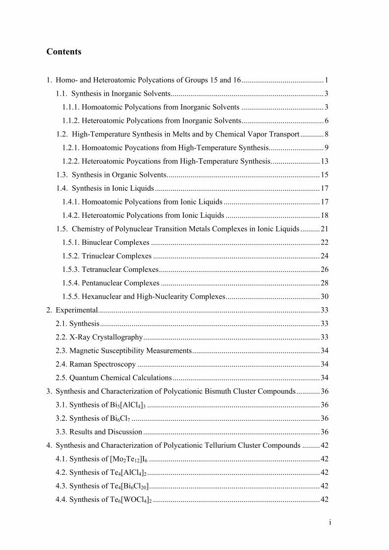
1. Homo- and Heteroatomic Polycations of Groups 15 and 16 .......................................... 1
1.1. Synthesis in Inorganic Solvents .............................................................................. 3
1.1.1. Homoatomic Polycations from Inorganic Solvents .......................................... 3
1.1.2. Heteroatomic Polycations from Inorganic Solvents .......................................... 6
1.2. High-Temperature Synthesis in Melts and by Chemical Vapor Transport ............ 8
1.2.1. Homoatomic Poycations from High-Temperature Synthesis. ........................... 9
1.2.2. Heteroatomic Poycations from High-Temperature Synthesis. ........................ 13
1.3. Synthesis in Organic Solvents. ............................................................................. 15
1.4. Synthesis in Ionic Liquids .................................................................................... 17
1.4.1. Homoatomic Polycations from Ionic Liquids ................................................. 17
1.4.2. Heteroatomic Polycations from Ionic Liquids ................................................ 18
1.5. Chemistry of Polynuclear Transition Metals Complexes in Ionic Liquids .......... 21
1.5.1. Binuclear Complexes ...................................................................................... 22
1.5.2. Trinuclear Complexes ..................................................................................... 24
1.5.3. Tetranuclear Complexes .................................................................................. 26
1.5.4. Pentanuclear Complexes ................................................................................. 28
1.5.5. Hexanuclear and High-Nuclearity Complexes ................................................ 30
2. Experimental ................................................................................................................. 33
2.1. Synthesis ................................................................................................................ 33
2.2. X-Ray Crystallography .......................................................................................... 33
2.3. Magnetic Susceptibility Measurements ................................................................. 34
2.4. Raman Spectroscopy ............................................................................................. 34
2.5. Quantum Chemical Calculations ........................................................................... 34
3. Synthesis and Characterization of Polycationic Bismuth Cluster Compounds ............ 36
3.1. Synthesis of Bi5[AlCl4]3 ........................................................................................ 36
3.2. Synthesis of Bi6Cl7 ................................................................................................ 36
3.3. Results and Discussion .......................................................................................... 36
4. Synthesis and Characterization of Polycationic Tellurium Cluster Compounds ......... 42
4.1. Synthesis of [Mo2Te12]I6 ....................................................................................... 42
4.2. Synthesis of Te4[AlCl4]2 ........................................................................................ 42
4.3. Synthesis of Te4[Bi6Cl20] ....................................................................................... 42
4.4. Synthesis of Te6[WOCl4]2 ..................................................................................... 42
ii
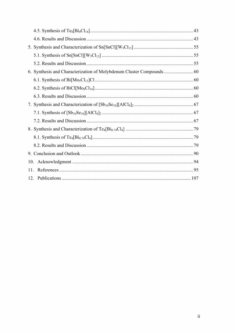
4.5. Synthesis of Te8[Bi4Cl14] ....................................................................................... 43
4.6. Results and Discussion .......................................................................................... 43
5. Synthesis and Characterization of Sn[SnCl][W3Cl13] .................................................. 55
5.1. Synthesis of Sn[SnCl][W3Cl13] ............................................................................. 55
5.2. Results and Discussion .......................................................................................... 55
6. Synthesis and Characterization of Molybdenum Cluster Compounds ......................... 60
6.1. Synthesis of Bi[Mo5Cl13]Cl ................................................................................... 60
6.2. Synthesis of BiCl[Mo6Cl14] ................................................................................... 60
6.3. Results and Discussion .......................................................................................... 60
7. Synthesis and Characterization of [Sb10Se10][AlCl4]2 .................................................. 67
7.1. Synthesis of [Sb10Se10][AlCl4]2 ............................................................................. 67
7.2. Results and Discussion .......................................................................................... 67
8. Synthesis and Characterization of Te4[Bi0.74Cl4] ......................................................... 79
8.1. Synthesis of Te4[Bi0.74Cl4] ..................................................................................... 79
8.2. Results and Discussion .......................................................................................... 79
9. Conclusion and Outlook ............................................................................................... 90
10. Acknowledgment ...................................................................................................... 94
11. References ................................................................................................................. 95
12. Publications ............................................................................................................. 107
Introduction
1
1. Homo- and Heteroatomic Polycations of Groups 15 and 16
The first synthesis of a chalcogen polycation was possibly carried out in 1798, when Klaproth
described that tellurium gradually dissolves in sulfuric acid to give a red solution [1].
Following him, in the early 19th century, Bucholz and Magnus prepared colored solution for
sulfur and selenium in sulfuric acid and oleum respectively [2]. It took more than 150 years
until the true nature of the species responsible for such coloration was interpreted when
Bjerrum et al. and Gillespie et al. confirmed spectroscopically that the species are polycations,
e.g. Te42+, S4
2+, or Se42+ [3, 4]. However, the first chalcogen polycation was isolated in 1962
by Bartlett et al. by reacting oxygen and PtF6, yielding O2[PtF6] containing the oxygen
polycation O2+ [5]. Later, X-ray crystallographic studies proved the existence and revealed the
shape of other chalcogen polycations thereby opening the way to an understanding of the
relations between composition, charge, structure, and bonding.
As far as the polycations of group 15 are concerned, the early investigations into the
nature of “BiCl” led to the discovery of the first bismuth polycation Bi95+. In 1908, Eggink
carried out the reduction of bismuth trichloride with elemental bismuth to synthesize “BiCl”
[2]. About 60 years later, X-ray crystallographic investigations by Corbett and co-workers
revealed the true composition to be Bi24Cl28 = Bi6Cl7 [6, 7]. In the crystal structure they found
tri-capped trigonal prismatic Bi95+ polycations accompanied by chlorido-bismuthate(III)
anions.
In the early 1970s, Paul et al. and Gillespie et al. provided spectroscopic evidence for
antimony, arsenic and phosphorus homoatomic polycations by analyzing different colored
solutions, obtained by oxidizing the respective element in protic acids or liquid SO2 [8, 9].
However, the first structurally characterized nitrogen polycation appeared in 2001, when
Christe et al. managed to isolate N5+ from anhydrous HF solution [10a]. A while later, Kloo
and co-workers obtained an antimony polycation Sb82+ from Ga/GaCl3–benzene media in
2004 [10b]. In addition to homoatomic, a number of heteroatomic polycations were also
reported by several research groups.
There are plenty of well-established methods for the synthesis of such polycations, all of
which need strongly polar media such as H2SO4, anhydrous HF, HSO3F, liquid SO2, molten
salts, e.g. Na[AlCl4], or GaX3-benzene media (X = Br, Cl). The particular species are
Introduction
2
converted to the polycationic clusters through; (i) oxidation using appropriate oxidants such
as AsF5, SbF5, WCl6, or MoOCl4 [11, 13], (ii) synproportionation in the presence of a strong
halogenide ion acceptor such as AlX3, ZrX4 or BiX3 (X = Cl, Br, I) [13–15], and (iii) reduction
with elemental Ga or oxidation by GaX3 in benzene (X = Cl, Br) [16].
Recently room temperature ionic liquids (RTIL) have been introduced as a new alternative
reaction medium for the synthesis of polycations and cluster compounds [17–23].
A number of review articles on the synthesis of polycations have been published by
Gillespie and co-workers, in which they highlighted the route using highly acidic media or
liquid SO2 and elucidated the structures of the several polycations [11]. Corbett reviewed the
homoatomic polycations of main group elements synthesized through the molten salts
approach [14c]. In 1989, Passmore et al. discussed in detail the nature of bonding and charge
delocalization in some of the unusual non-classically bonded homoatomic polycations [24].
The latest reviews date from 2000: Passmore and co-workers surveyed all known
homoatomic polycations of the chalcogens and halogens, studied their bonding, reaction
kinetics and thermodynamics to estimate the stabilities using Born-Fajans-Haber cycles [25].
Meanwhile, Beck contributed two review articles, first in 1994, on the preparation of
chalcogen polycations via chemical vapor transport (CVT) [12], a new synthetic route leading
to novel polycations [13a], and second in 1997, in which he treated the chalcogens
polycations with respect to their structure and bonding according to the Zintl concept [13b]. In
1999, Kloo et al. reviewed different preparation routes for the naked clusters of the post-
transition elements and explained their structure and bonding [26]. A review article on sub-
valent bismuth compounds was published by Ruck in 2001, which covers the whole spectrum
from partially oxidized porous metals, through one- and two-dimensional metals, to
semiconducting ionic or molecular cluster compounds including new bismuth polycations
[27]. In 2004, two comprehensive accounts were presented separately by Krossing and
Sheldrick, focusing on the cages and clusters of the group 15 elements and chalcogens
respectively [28, 29]. They concentrated mainly on the bonding and geometries of the isolated
cationic, neutral, and anionic homoatomic cages and clusters.
The last 12 years have provided four new homoatomic polycations, i.e. N5+, Bi5
+, Bi62+,
Sb82+, and 15 new heteroatomic polycations with hitherto unprecedented structures e.g.
(S4N5)+, (Bi4E4)
4+ (E = S, Se, Te), 1 [Sb2Te2]
+, (Pd@Bi10)4+, (Au@Bi10)
5+, (Bi10Au2)6+,
(Bi8Si2)3+, (Sb7S8Br2)
3+, 2 [A2Te2Br]+ (A = Bi, Sb), (As3S5)
+, (Bi3GaS5)2+, and (Sb10Se10)
2+
Introduction
3
4Se + 6H2S2O7 Se42++ 2HS3O10
– + 5H2SO4 + SO2 (1.1)
[Table 1.1]. The synthetic schemes for the polycationic clusters are regrettably limited,
because they need large, weakly basic, weakly coordinating and non oxidizing anions to
stabilize them in solution and in solid state. Until now, four different successful preparative
methods have been reported in literature.
1.1. Synthesis in Inorganic Solvents
The superacid route to polycationic clusters was first introduced by Klaproth for the synthesis
of Te42+ by the oxidation of the elemental tellurium in concentrated sulfuric acid where one-
component superacids were used both as the oxidizing agent and as the source of the
necessary weak Lewis base [1]. The superacids are practical and successful for the synthesis
of clusters in solution but several difficulties are associated with crystallization and recovery
of solid cluster phases [30]. Gillespie, Passmore and co-workers put their efforts to overcome
these difficulties by using highly oxidizing agents like pentafluorides of antimony and, even
better, arsenic in superacids or inert solvents (most often liquid SO2) to prepare ligand-free
“naked” clusters of post-transition elements. This method proved to be very promising and
resulted in the fabrication of several new compounds containing variety of polycationic
clusters of chalcogens, bismuth, and halogens [11, 24, 25].
1.1.1. Homoatomic Polycations from Inorganic Solvents
Numerous homoatomic polycations were synthesized using superacidic media and liquid SO2.
They were characterized spectroscopically in solution and through X-ray crystallography in
the form of solid phases. The tetraatomic cations E42+ (E = S, Se, Te) were the earliest to be
characterized. In 1971, the first compound Se4[HS2O7]2 was crystallized from oleum in the
form of orange needles containing Se42+ polycations. Originally, the synthesis was performed
according to Klaproth by the oxidation of selenium in disulfuric acid [31], equation (1.1).
Other chalcogen polycationic compounds were more difficult to isolate from the
solution, and it was in early 1980s that the colorless crystals of S4[AsF6]2·0.6SO2 were
obtained by reacting S8 with AsF5 in the presence of traces of bromine in liquid SO2. Hence,
the square planar and discrete molecular entity S42+ was finally characterized [32]. The
tellurium homologue Te42+ had already been isolated in 1970 as Te4[AlCl4]2 through a melting
Introduction
4
reaction and its crystal structure was determined by Corbett and co-workers [14b]. The same
polycation was also found in Te4[SbF6]2 as dark red crystals by reacting a mixture of tellurium
and germanium with SbF5 in liquid SO2 [33]. The tetraatomic E42+ polycations show charge
delocalization and are incompatible with the Zintl concept. The E42+ polycations carry 22
valence electrons and, according to the Zintl concept, they should contain two double and two
triple bound chalcogen atoms in a butterfly conformation where both positive charges are
formally localized. Instead, the E42+ cations show delocalization, which was confirmed by a
series of theoretical investigations at different computational levels [34]. The considerable
aromatic π stabilization of E42+ cations was concluded from all calculations.
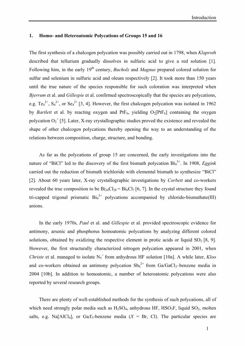
The trigonal prismatic Te64+ polycation had appeared first in 1979 as Te6[AsF6]4·2AsF3
and Te6[AsF6]4·2SO2 by the oxidation of elemental tellurium with AsF5 in AsF3 or liquid SO2
(Figure 1.1a) [35]. Te64+ is also an example of non-classical structure which has 32 valence
electrons. In accordance with the Zintl concept, the number of triple bonded Te atoms should
be reduced from six to four but Te64+ shows the phenomenon of bond delocalization and
therefore adopts a non-classical structure.
The heptaatomic tellurium polycation is known as the repetition unit of the polymeric
chain 1 [Te7
2+]. Te7[AsF6]2 was synthesized by reacting Te4[AsF6]2 with Fe(CO)5 in liquid
SO2, in which the iron carbonyl is presumably responsible for the reduction of Te42+ to Te7
2+.
The infinite chain of the polycation consists of six-membered tellurium rings connected
through bridging, triply bonded tellurium atoms, which carry the formal positive charges and
represent a Zintl precise structure (Figure 1.4d) [36].
The eight-membered E82+ homologues of sulfur and selenium polycations were also
prepared. They have similar bicyclic structures derived from the crown shaped ring of the
neutral S8 or Se8 molecules. Flipping one atom from the exo to the endo position, excluding
an electron pair and deformation of the ring to an oval leads to a bicyclic structure which
shows slight distortion from Cs symmetry. The S82+ polycation was obtained in 1971 as
S8[AsF6]2 by the oxidation of sulfur with AsF5 in HF (Figure 1.1c) [37], but the crystallization
of compounds containing Se82+ polycations was finally successful in 1987, when elemental
tellurium and selenium were oxidized by AsF5 in liquid SO2 to get dark green crystals of
(Te6)(Se8)[AsF6]6·SO2 [38]. However, Se82+ had already been isolated through molten salts
approach as Se8[AlCl4]2 and structurally characterized by Corbett et al. in 1969 [39].
Introduction
5
10Bi + 9AsF5 2Bi5[AsF6]3·2SO2 + 3AsF3 (1.2) SO2
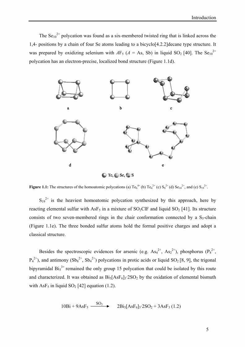
The Se102+ polycation was found as a six-membered twisted ring that is linked across the
1,4- positions by a chain of four Se atoms leading to a bicyclo[4.2.2]decane type structure. It
was prepared by oxidizing selenium with AF5 (A = As, Sb) in liquid SO2 [40]. The Se102+
polycation has an electron-precise, localized bond structure (Figure 1.1d).
Figure 1.1: The structures of the homoatomic polycations (a) Te64+ (b) Te4
2+ (c) S82+ (d) Se10
2+, and (e) S192+.
S19
2+ is the heaviest homoatomic polycation synthesized by this approach, here by
reacting elemental sulfur with AsF5 in a mixture of SO2ClF and liquid SO2 [41]. Its structure
consists of two seven-membered rings in the chair conformation connected by a S5-chain
(Figure 1.1e). The three bonded sulfur atoms hold the formal positive charges and adopt a
classical structure.
Besides the spectroscopic evidences for arsenic (e.g. As42+, As2
2+), phosphorus (P82+,
P42+), and antimony (Sb8
2+, Sb42+) polycations in protic acids or liquid SO2 [8, 9], the trigonal
bipyramidal Bi53+ remained the only group 15 polycation that could be isolated by this route
and characterized. It was obtained as Bi5[AsF6]3·2SO2 by the oxidation of elemental bismuth
with AsF5 in liquid SO2 [42] equation (1.2).
Introduction
6
1.1.2. Heteroatomic Polycations from Inorganic Solvents
Besides plenty of homoatomic polycations of groups 15 and 16, a small number of
heteroatomic polycations have been discovered. Among them, polycations that are built by
two different kinds of chalcogen atoms (E) represent the largest group. Gillespie et al.
synthesized a variety of such mixed polycations from liquid SO2 or in a liquid mixture of
SO2ClF/SO2 and structurally characterized them by means of X-ray crystallography.
For the square (E4)2+ polycations, a number of mixed group 16 polycations were isolated
e.g. (Te2Se2)2+, (Te3Se)2+, or (S3Se)2+ [43]. The non-classical (E4)
2+ polycations show
significant deviations from the square-planar conformation. They were obtained as salts of
either fluorido-stibates(III) or fluorido-arsenates(III) by reacting the respective elements with
SbF5 or AsF5 in liquid SO2.
The six-membered (E6)2+ species are also known, e.g. (Te3S3)
2+, (Te2S4)2+ or (TexSe6–x)
2+
[44], they are almost isostructural having a six-membered ring in boat-conformation (Figure
1.2b, 1.2f). A series of heteroatomic (TexSe6–x)2+ polycations were prepared as described
above, but for the synthesis of (Te3S3)2+ two different methods were applied using liquid SO2
as the reaction medium: (i) by reacting Te4[AsF6]2 and S8[AsF6]2, (ii) by reacting a mixture of
Te/S with AsF5. All six-membered heteroatomic (E6)2+ cations follow the Zintl concept and
exhibit classical structures with localized bonds.
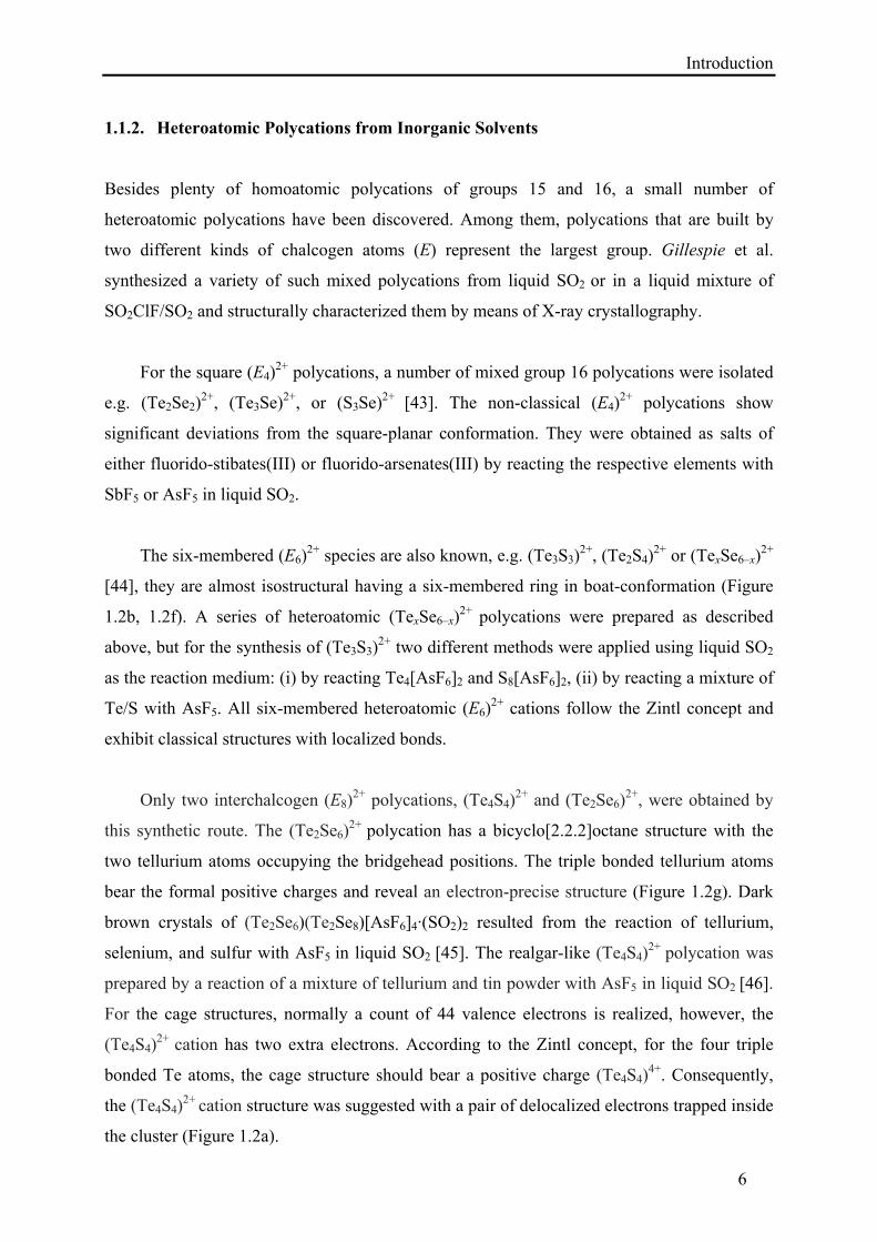
Only two interchalcogen (E8)2+ polycations, (Te4S4)
2+ and (Te2Se6)2+, were obtained by
this synthetic route. The (Te2Se6)2+ polycation has a bicyclo[2.2.2]octane structure with the
two tellurium atoms occupying the bridgehead positions. The triple bonded tellurium atoms
bear the formal positive charges and reveal an electron-precise structure (Figure 1.2g). Dark
brown crystals of (Te2Se6)(Te2Se8)[AsF6]4·(SO2)2 resulted from the reaction of tellurium,
selenium, and sulfur with AsF5 in liquid SO2 [45]. The realgar-like (Te4S4)2+ polycation was
prepared by a reaction of a mixture of tellurium and tin powder with AsF5 in liquid SO2 [46].
For the cage structures, normally a count of 44 valence electrons is realized, however, the
(Te4S4)2+ cation has two extra electrons. According to the Zintl concept, for the four triple
bonded Te atoms, the cage structure should bear a positive charge (Te4S4)4+. Consequently,
the (Te4S4)2+ cation structure was suggested with a pair of delocalized electrons trapped inside
the cluster (Figure 1.2a).

Introduction
7
The ten-membered (E10)2+ heteroatomic polycations, such as (Te2Se8)
2+, (Te3.7Se6.3)2+ or,
(Te4.5Se5.5)2+, are the heaviest species synthesized employing this route [45, 47]. The structure
of these cations is similar to Se102+ (Figure 1.2e).
Very few heteroatomic polycations that contain elements of groups 15 and 16 are known.
The mixed arsenic/chalcogen polycations, (As3S4)+ and (As3Se4)
+, were also found by
Gillespie et al. [48a]. For the synthesis of (As3S4)+, they treated β-As4S4 with AsF5 or SbF5 to
get the corresponding salts, while in case of (As3Se4)+, the related amounts of 1:1 or 4:3 As-
Se-melts were reacted with either AsF5 or SbF5. Both (As3S4)+ and (As3Se4)
+ cations have Cs
symmetry and are isostructural to P4S3 or P73– [49], which can be considered to be derived
from a tetrahedron of three arsenic atoms and one sulfur or selenium atom with three of its
edges bridged by sulfur or selenium atoms (Figure 1.2c). These heteroatomic polycations
show classical, electron-precise structures. Some mixed nitrogen/sulfur polycations were also
reported e.g. (SN)+, (SNS)+, (S4N4)2+, (S6N4)
2+, or (S5N5)+, they were isolated from liquid
SO2, HSO3Cl, or SOCl2 using a variety of counter ions like [Al(OC(CF3)3)4]–, AlCl4
–, SbF6–,
AsF6–, or SbCl6
– etc. [48b–48e].
Figure 1.2: The structures of the heteroatomic polycations (a) (Te4S4)2+ (b) (Te3S3)
2+ (c) (As3S4)+ (d) (S4N4)
2+ (e)
(Te2Se8)2+ (f) (Te2Se4)
2+ (g) (Te2Se6)2+, and (h) (S5N5)
+.
The phenomenon of bond delocalization was observed in such heteroatomic polycations
Introduction
8
(Figure 1.2d, 1.2h). The use of strong oxidizing agents like AsF5 or SbF5 for the post-
transition metal cluster synthesis has numerous advantages, e.g. reactions may be carried out
in protic acids or in liquid SO2 at ambient or lower temperature. In addition, the reaction by-
products and the solvents are volatile and can be easily separated from the product. However,
there are some demerits, which undermine this synthetic approach, e.g. the use of highly toxic
AsF5 or SbF5. Moreover, the production of less-volatile by-product SbF3 on reduction is also a
troublesome because it can accept F– ions to form SbF6– or Sb2F11
– as counter-ions. In this
perspective, clean syntheses have frequently been made difficult or impossible by co-
precipitation of the SbF3 or by mixed oxidation state anion formation between SbF5, SbF3,
and F– ions. Otherwise reactions, which lead to a solid residue, yielded contaminated products
because of the very low volatility of SbF3 [30]. Moreover, this type of synthesis requires
sophisticated glassware, and chemicals like AsF5 which are very expensive.
1.2. High-Temperature Synthesis in Melts and by Chemical Vapor Transport
The early investigation into the nature of the subchloride “BiCl” fascinated synthetic chemists
to explore a new approach to prepare, isolate and characterize the polycationic cluster
compounds. This inspiration resulted in the discovery of the high temperature route or molten
salts approach, which was mainly developed by Corbett and co-workers [14]. This route
gifted not only novel polycations, but also assisted to isolate known species, which were not
yet well characterized. Low-melting halogenides with melting points above room temperature
(e.g. SbCl3: mp = 73 °C, AlCl3: mp = 193 °C, or GaCl3: mp = 80 °C) were used as the
reaction media. The most frequently used method to synthesize polycations in melts is the
synproportionation, which also proved helpful to solve the issue of “BiCl”. The single crystals
analysis proved the existence of Bi24Cl28 = Bi6Cl7 instead of BiCl, which has a structure
consisting of tri-capped trigonal prismatic Bi95+ polycations accompanied by chlorido-
bismuthate(III) anions (Figure 1.3e) [6, 7]. Later, Krebs et al. managed to modify the scheme
by altering the proportion of molten salts to isolate other bismuth polycations [50]. A major
obscurity with the synproportionation reaction is that the number of redox reactions that can
take place is limited.
Beck brought key improvement in this scheme, which shows apparently similarities to
the traditional molten salt route, but it avoids the limitations of synproportionations. This
upgraded and advanced strategy is known as chemical vapor transport (CVT), in which a
Introduction
9
volatile, high-valent transition metal halogenide acts both as halide acceptor and as oxidizing
agent [13a]. Ruck et al. further expanded the scope of the higher temperature route by
incorporating transition metals in the structure of the bismuth polycations [51]. To
summarize, by the higher temperature route, besides known polycations, novel homo- and
heteroatomic polycations of groups 15 and 16 also became accessible.
1.2.1 . Homoatomic Polycations from High-Temperature Synthesis
Employing the high temperature synthetic route allowed the isolation and subsequent
structure determination of polycationic compounds. Bi53+ and Bi8
2+ polycations were first
reported by Bjerrum et al. in 1967 during the spectrochemical investigation of bismuth metal
in dilute solutions of BiCl3 in liquid NaCl-AlCl3 and KCl-ZnCl2 mixtures [52]. Corbett
attempted to crystallize Bi5[AlCl4]3 and Bi8[AlCl4]2 from NaAlCl4 melts but due to slow
equilibration, supercooling phenomena, and problems with twinning, no suitable single-
crystals were obtained in the early investigations [14a]. Krebs and co-workers reconsidered
and refined this synthetic route successfully to obtain good quality single-crystals, which
allowed a better structural characterization of the salts Bi5[AlCl4]3 and Bi8[AlCl4]2. The Bi53+
polycation proved to possess trigonal bipyramidal conformation, while Bi82+ is a square
antiprism. (Figure 1.3a, 1.3d) [50].
Later, the square pyramidal Bi5+ and the distorted octahedral Bi6
2+ polycations were found
simultaneously in the compounds Bi34Ir3Br37 and Bi12−xMX13−x (M = Rh, Ir; X = Cl, Br; x ≤ 1)
(Figure 1.3b, 1.3c) [53]. A better structural characterization of the Bi62+ cation, as a distorted
octahedron with an opened edge, became possible with the discovery of Bi6[PtBi6Cl12] [54].
Modified Wade’s rules have proven to be a very convenient tool for qualitative
estimation of the geometries of homoatomic bismuth clusters, where the 6s electrons form the
lone pairs and only the 6p electrons are used in cluster bonding. The geometries of the well-
known bismuth polycations are found to be in agreement with the prescribed skeletal
electrons (SE) e.g. Bi5+ (nido, 14 SE) [53], Bi5
3+ (closo, 12 SE) [14a, 15, 16b, 16c, 50a], Bi62+
(nido, 16 SE) [53, 54], Bi82+ (arachno, 22 SE) [50b, 55], Bi10
4+ (arachno, 26 SE) [51b–51f].
However, according to Wade’s rules, the Bi95+ polycation with 22 SE should adopt a nido
conformation with the shape of a monocapped square antiprism (C4v), while in most of the
crystal structures it is found to be rather close to the tri-capped trigonal prism (D3h), that is a
Introduction
10
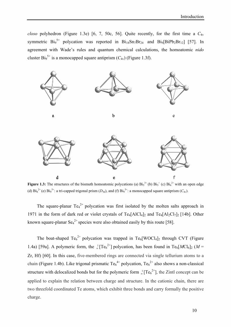
closo polyhedron (Figure 1.3e) [6, 7, 50c, 56]. Quite recently, for the first time a C4v
symmetric Bi95+ polycation was reported in Bi18Sn7Br24 and Bi9[BiPb2Br12] [57]. In
agreement with Wade’s rules and quantum chemical calculations, the homoatomic nido
cluster Bi95+ is a monocapped square antiprism (C4v) (Figure 1.3f).
Figure 1.3: The structures of the bismuth homoatomic polycations (a) Bi5
3+ (b) Bi5+ (c) Bi6
2+ with an open edge
(d) Bi82+ (e) Bi9
5+: a tri-capped trigonal prism (D3h), and (f) Bi95+: a monocapped square antiprism (C4v).
The square-planar Te42+ polycation was first isolated by the molten salts approach in
1971 in the form of dark red or violet crystals of Te4[AlCl4]2 and Te4[Al2Cl7]2 [14b]. Other
known square-planar Se42+ species were also obtained easily by this route [58].
The boat-shaped Te62+ polycation was trapped in Te6[WOCl4]2 through CVT (Figure
1.4a) [59a]. A polymeric form, the 1 [Te6
2+] polycation, has been found in Te6[MCl6]2 (M =
Zr, Hf) [60]. In this case, five-membered rings are connected via single tellurium atoms to a
chain (Figure 1.4b). Like trigonal prismatic Te64+ polycation, Te6
2+ also shows a non-classical
structure with delocalized bonds but for the polymeric form 1 [Te6
2+], the Zintl concept can be
applied to explain the relation between charge and structure. In the cationic chain, there are
two threefold coordinated Te atoms, which exhibit three bonds and carry formally the positive
charge.
Introduction
11
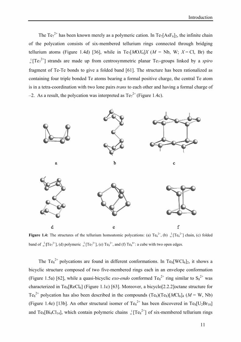
The Te72+ has been known merely as a polymeric cation. In Te7[AsF6]2, the infinite chain
of the polycation consists of six-membered tellurium rings connected through bridging
tellurium atoms (Figure 1.4d) [36], while in Te7[MOX4]X (M = Nb, W; X = Cl, Br) the
1 [Te7
2+] strands are made up from centrosymmetric planar Te7-groups linked by a spiro
fragment of Te-Te bonds to give a folded band [61]. The structure has been rationalized as
containing four triple bonded Te atoms bearing a formal positive charge, the central Te atom
is in a tetra-coordination with two lone pairs trans to each other and having a formal charge of
–2. As a result, the polycation was interpreted as Te72+ (Figure 1.4c).
Figure 1.4: The structures of the tellurium homoatomic polycations: (a) Te62+, (b) 1
[Te62+] chain, (c) folded
band of 1 [Te7
2+], (d) polymeric 1 [Te7
2+], (e) Te82+, and (f) Te8
4+: a cube with two open edges.
The Te82+ polycations are found in different conformations. In Te8[WCl6]2, it shows a
bicyclic structure composed of two five-membered rings each in an envelope conformation
(Figure 1.5a) [62], while a quasi-bicyclic exo-endo conformed Te82+ ring similar to S8
2+ was
characterized in Te8[ReCl6] (Figure 1.1c) [63]. Moreover, a bicyclo[2.2.2]octane structure for
Te82+ polycation has also been described in the compounds (Te6)(Te8)[MCl6]4 (M = W, Nb)
(Figure 1.4e) [13b]. An other structural isomer of Te82+ has been discovered in Te8[U2Br10]
and Te8[Bi4Cl14], which contain polymeric chains 1 [Te8
2+] of six-membered tellurium rings
Introduction
12
in chair conformation connected through Te2 bridge (Figure 1.5b) [64]. Te84+, a higher
oxidized polycation stabilized in the salt Te8[VOCl4]2, can be interpreted as a dimer formed
by a pair of coplanar Te42+ rings. In fact, the Te8
4+ forms a deformed cube with two opened
edges, leaving four of the eight Te atoms triple bonded (Figure 1.4f) [65]. Among different
Te8n+ forms, the bicyclo[2.2.2]octane-type Te8
2+, the higher oxidized Te84+, and polymeric
chain found in Te8[U2Br10] and Te8[Bi4Cl14] show classical, Zintl precise structures and
possess tri-coordinated tellurium atoms bearing the formal positive charges.
The octaselenium Se82+ polycation was first obtained through synproportionation in 1971
in the form of dark reddish brown crystals of Se8[AlCl4]2 [66]. Se82+ is isostructural to S8
2+
and possesses a cyclic structure with approximately Cs symmetry (Figure 1.1c).
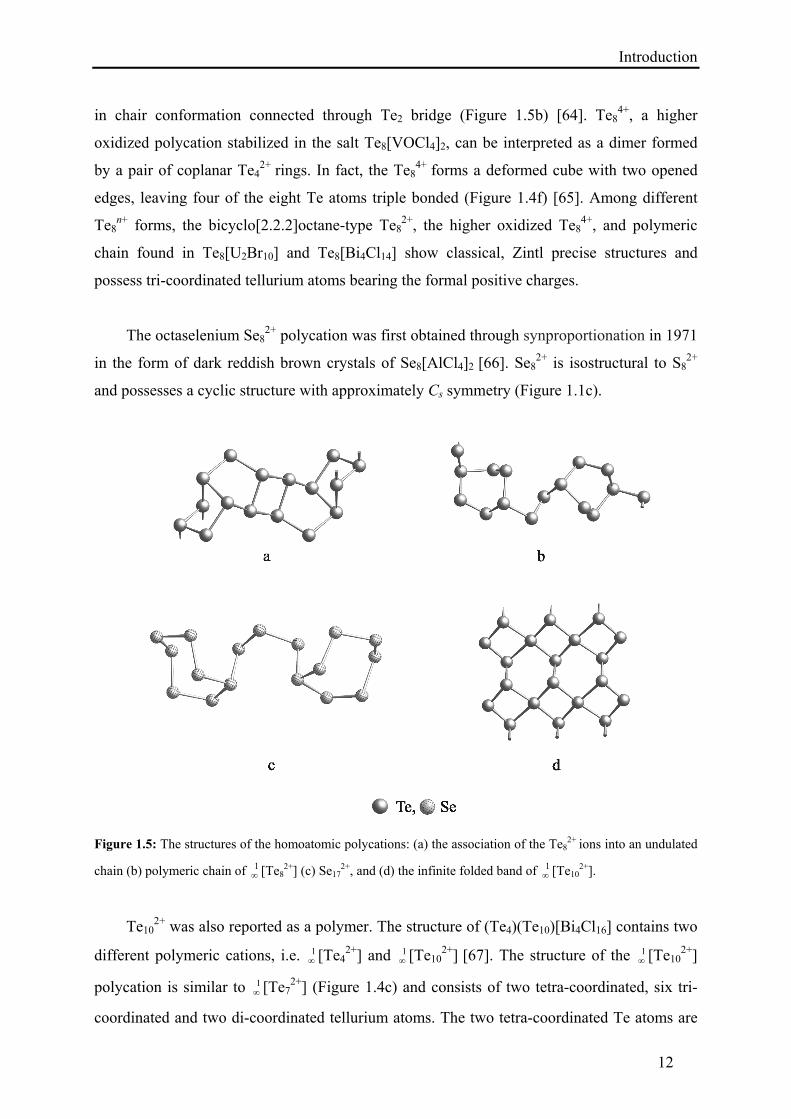
Figure 1.5: The structures of the homoatomic polycations: (a) the association of the Te82+ ions into an undulated
chain (b) polymeric chain of 1 [Te8
2+] (c) Se172+, and (d) the infinite folded band of 1
[Te102+].
Te102+ was also reported as a polymer. The structure of (Te4)(Te10)[Bi4Cl16] contains two
different polymeric cations, i.e. 1 [Te4
2+] and 1 [Te10
2+] [67]. The structure of the 1 [Te10
2+]
polycation is similar to 1 [Te7
2+] (Figure 1.4c) and consists of two tetra-coordinated, six tri-
coordinated and two di-coordinated tellurium atoms. The two tetra-coordinated Te atoms are
Introduction
13
members of two adjacent planar four-membered rings and the six tricoordinated centers link
the planar Te102+ units forming an infinite folded band (Figure 1.5d).
The largest discrete homoatomic polycation is Se17
2+, which was synthesized by the
oxidation of elemental selenium with WCl6 through CVT [68]. The electron-precise structure
of Se172+ is similar to S19
2+ and consists of two seven-membered rings, which are linked by a
three-membered selenium chain (Figure 1.5c).
1.2.2. Heteroatomic Polycations from High-Temperature Synthesis
In addition to homoatomic, a number of heteroatomic polycations were obtained through the
higher temperature routes. Beck et al. synthesized a small number of mixed polycations of
groups 15 and 16, while Ruck et al. focused on the incorporation of transition metals and post
transition elements into the bismuth polycations and managed to prepare a couple of novel
heteroatomic clusters. A most recent review published by Braunschweig et al. emphasizes on
the ability of bismuth species to build mixed clusters with transition metals [69], generating a
wide variety of structures containing transition metal–bismuth bonds [70].
A series of mixed polycations (Bi4E4)4+ were obtained from acidic NaCl/AlCl3 melts (E =
S, Se, Te). These mixed polycations reveal crystallographic S4 symmetry, which is slightly
distorted from a regular cube, whose corners are occupied alternately by Bi and E atoms
(Figure 1.6c) [71].
1 [Sb2Te2]
+ is a polymeric heteroatomic polycation, which forms strands made up of
stacked Sb2Te2-rings. These rings are connected with their neighbors alternating via two,
three, or four covalent bonds. Mostly Sb-Te bonds are present, in smaller number Sb-Sb
bonds, while Te-Te bonds are not observed (Figure 1.6d) [72].
The mixed chalcogen polycations (Se4Te3)2+ and 1
[Se4.85Te3.15]2+ were obtained by
reacting Te6[WOCl4]2 with selenium, or Se/Te mixtures with WOCl4 [73]. The (Se4Te3)2+
polycation is almost similar to polymeric 1 [Te7
2+], built by four-membered planar Te2Se2
rings connected via three atomic Se–Te–Se bridges in the 1,3 positions of the rings (Figure
1.6f). The polymeric cation 1 [Se4.85Te3.15]
2+ consists of five-membered rings that are
connected in the 1,3-positions by three-atomic bridges.
Introduction
14
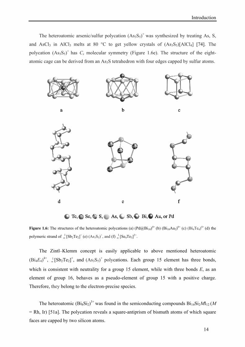
The heteroatomic arsenic/sulfur polycation (As3S5)+ was synthesized by treating As, S,
and AsCl3 in AlCl3 melts at 80 °C to get yellow crystals of (As3S5)[AlCl4] [74]. The
polycation (As3S5)+ has Cs molecular symmetry (Figure 1.6e). The structure of the eight-
atomic cage can be derived from an As3S tetrahedron with four edges capped by sulfur atoms.
Figure 1.6: The structures of the heteroatomic polycations (a) (Pd@Bi10)4+ (b) (Bi10Au2)
6+ (c) (Bi4Te4)4+ (d) the
polymeric strand of 1 [Sb2Te2]
+ (e) (As3S5)+, and (f) 1
[Se4Te3]2+.
The Zintl–Klemm concept is easily applicable to above mentioned heteroatomic
(Bi4E4)4+, 1
[Sb2Te2]+, and (As3S5)
+ polycations. Each group 15 element has three bonds,
which is consistent with neutrality for a group 15 element, while with three bonds E, as an
element of group 16, behaves as a pseudo-element of group 15 with a positive charge.
Therefore, they belong to the electron-precise species.
The heteroatomic (Bi8Si2)3+ was found in the semiconducting compounds Bi14Si2MI12 (M
= Rh, Ir) [51a]. The polycation reveals a square-antiprism of bismuth atoms of which square
faces are capped by two silicon atoms.
Introduction
15
The stuffed polycation (Pd@Bi10)4+ was discovered in Bi14PdBr16 and Bi16PdCl22 [51b,
51c]. It consists of a pentagonal antiprism Bi104+ and an uncharged palladium atom at the
centre (Figure 1.6a).
The isoelectronic and isostructural (Au@Bi10)5+ is a part of the semiconducting
compounds AuBi14–δSn2+δX21–δ (δ ≈ 0.4) [51e]. The capped polycation (Bi10Au2)6+, a
heteroicosahedron with Au+ cations in 1,12-positions, was found as the central part of the
molecule (Bi10Au2)[SbBi3Br9]2 (Figure 1.6b) [51d]. The heteroatomic cluster cation
(Bi10Au2)6+ was also reported in a series of compounds (Bi10Au2)[EBi3X9]2 (E = As, Bi; X =
Cl, Br) [51f]. Disregarding the 6s electrons, which do not contribute because of their
stabilization by relativistic effects, the Bi104+ polyhedron with 10·3–4 = 26 electrons in the
skeleton meets the expectations for an electron-precise arachno-cluster according to the
Wade–Mingos classification (2n + 6 = 26 electrons for bonding within the cluster).
In the molten salt approach, the addition of an excess of a more acidic halogenide is the
obvious way to increase the yield and to get good quality crystals. These salts may provide
effective, alternative route to sub-valent compounds. This is exemplified by the improved
synthesis of Bi6Cl7 from Bi and BiC13 in SbCl3 melts [50c]. Likewise, GaC13 melts can be
used to synthesize Bi53+ polycations through synproportionations [75]. Thus different Lewis
acids are available, which can effectively enhance the number of possibilities of polycation
and cluster synthesis using this scheme. Alternatively, a stronger oxidizing agent might be
expected to be required in systems where the synproportionation fails. Although, the higher
temperature route is comparatively successful and provided a large number of novel
polycations, there are yet some problems associated with it, e.g. (i) contamination with solid
by-products, especially in the case of peritectically forming compounds, (ii) long annealing
time, (iii) kinetic hindrance of solid-solid reactions, and (iv) the risk of product decomposition
in case of thermally unstable compounds.
1.3. Synthesis in Organic Solvents
Kloo and co-workers introduced a new room temperature route in 1995 using Ga/GaX3–
benzene media (X = Cl, Br) [26]. The use of benzene as solvent in the synthesis of clusters is
useful in many aspects, since the solvent is inexpensive, easy to handle, and can be used at
room temperature without specially designed glassware or other dedicated laboratory
Introduction
16
equipment. Likewise, the isolation of solid polycationic compounds from the benzene
solutions is conveniently performed by extraction with heptane or mesitylene. Moreover,
gallium(III) halogenides have some unique properties, which make them ideal candidates as
reagents for the synthesis of main group polycations and transition metal clusters, e.g. high
solubility (up to 50 mol % in benzene), Lewis acidity, and the reducing ability of Ga/GaX3–
benzene mixtures. Taking into account these characteristics, three different procedures were
applied to synthesize polycations; (i) by synproportionation of Bi and BiX3 in GaX3-benzene
solutions to synthesize bismuth polycations in both chloride and bromide media, (ii) by
reduction of the post-transition metal halogenides with a mixture of Ga/GaX3 in benzene, and
(iii) by oxidation of the post-transition metals with GaX3 in benzene. Kloo et al. synthesized
and isolated successfully some homoatomic polycations of antimony, bismuth, and tellurium.
Besides the synthesis of known polycations like Te42+ [16a, 16b], Bi5
3+ [16c], and Bi82+
[16b, 16c] by this room temperature method, for the first time an antimony polycation Sb82+,
was obtained [10b, 16b]. All these polycations were isolated as salts of halogenido-
gallates(III). The polycation Sb82+ has square-antiprismatic D4d symmetry, which is analogous
to the previously known Bi82+ cation (Figure 1.3d).
Considering the toxicity of benzene in the above mentioned procedure, later Kloo and
co-workers used an alternative approach. Here benzene was replaced by dichloromethane to
achieve the same goals. Dichloromethane had also been used earlier for the synthesis and
crystallization of some mixed nitrogen/sulfur polycations, e.g. (SN)+, (SNS)+, or (S4N5)+
[76a–76c]. To synthesize bismuth clusters, Kloo and co-workers performed a two-step
reaction, first to react Ga and GaCl3 in order to get a crystalline adduct, which was
subsequently treated with BiCl3 in dichloromethane. Within a couple of weeks, they obtained
a red/orange powder of Bi5[GaCl4]3. Attempts to get single crystals were not successful.
Moreover, the low reaction rate in dichloromethane is believed to be an effect of the
significantly lower concentration of gallium metal in this solvent [76d].
The synthesis of main group polycations using GaX3-benzene solutions facilitated to
isolate good quality single-crystals in some cases, e.g. for the novel antimony polycation. On
the other hand, this route cannot avoid some demerits, e.g. the use of toxic and cancer causing
benzene [77], limitations in temperature (reactions could only be performed in the liquid
range of the solvent), and general problems with controlled crystallization [16b, 16c].
Introduction
17
1.4. Synthesis in Ionic Liquids
RTIL have opened new opportunities in the field of material synthesis and have provided new
soft and low-temperature routes to inorganic solids that are usually prepared by high-
temperature reactions. RTIL have distinct physical properties such as high thermal stability,
wide liquid range, negligible vapor pressure, good ionic conductivity, and high solubility of
both organic and inorganic substances [78, 79]. The inherent thermal stability of RTIL
permits access to low and moderate temperatures at which kinetically stabilized phases can be
obtained. The use of a soft-chemical approach is common in organic synthesis [78], catalysis
[80], polymer science [79], nanotechnology [81], and in the synthesis of clathrates [82], and
zeolites [83]. However, the application of this technique to prepare polycationic cluster
compounds was relatively unexplored. Recently, Ruck et al., Kanatzidis et al., and Feldmann
et al. expanded effectively the span of this approach and synthesized a couple of new
polycations of groups 15 and 16 [17–23]. The key factors of this new synthetic route are: (i)
very high solubility of the elements (e.g. Bi, Te, Sb, Se, Ga, In) and their halogenides allow
reactions under mild conditions involving one-pot synthesis; (ii) low-temperature synthesis
eliminates the risk of product decomposition; (iii) easier reproducibility of the products; (iv)
controllable parameters, such as solvent acidity, oxidizing/reducing agent, or halide acceptor,
allow modifying the synthesis with the objective to crystallize different compounds. It has
been observed that synproportionation, oxidation, and reduction could be easily carried out in
RTIL for clusters synthesis e.g. (i) by synproportionation Bi53+ [17], Te4
2+ [19], Te41.78+ [84],
and Te82+ [85] polycations were obtained; (ii) by oxidation of elemental tellurium with
WOCl4, Te62+ was prepared [19], and (iii) by reduction of BiCl3 with indium metal Bi9
5+ was
synthesized [84].
1.4.1. Homoatomic Polycations from Ionic Liquids
In addition to the synthesis of some known homoatomic polycations like Te42+, Te6
2+, Te82+,
Bi53+, and Bi9
5+ by this method, a partially reduced square-planar Te41.78+ polycation was also
isolated. The Te41.78+ polycation was found in Te4[Bi0.74Cl4], synthesized by treating Te,
TeCl4, and BiCl3 at room temperature in the Lewis–acidic IL [bmim]Cl/AlCl3 (mole ratio =
1 : 2, [bmim]+: 1-n-butyl-3-methylimidazolium). The incommensurately modulated composite
structure of Te4[Bi0.74Cl4] consists of stacks of Te4 rings and chloridobismuthate strands. The
Introduction
18
Te41.78+ polycation is a four-membered ring in a slightly distorted square-planar conformation
and is similar to Te42+ [14b, 86].
1.4.2. Heteroatomic Polycations from Ionic Liquids
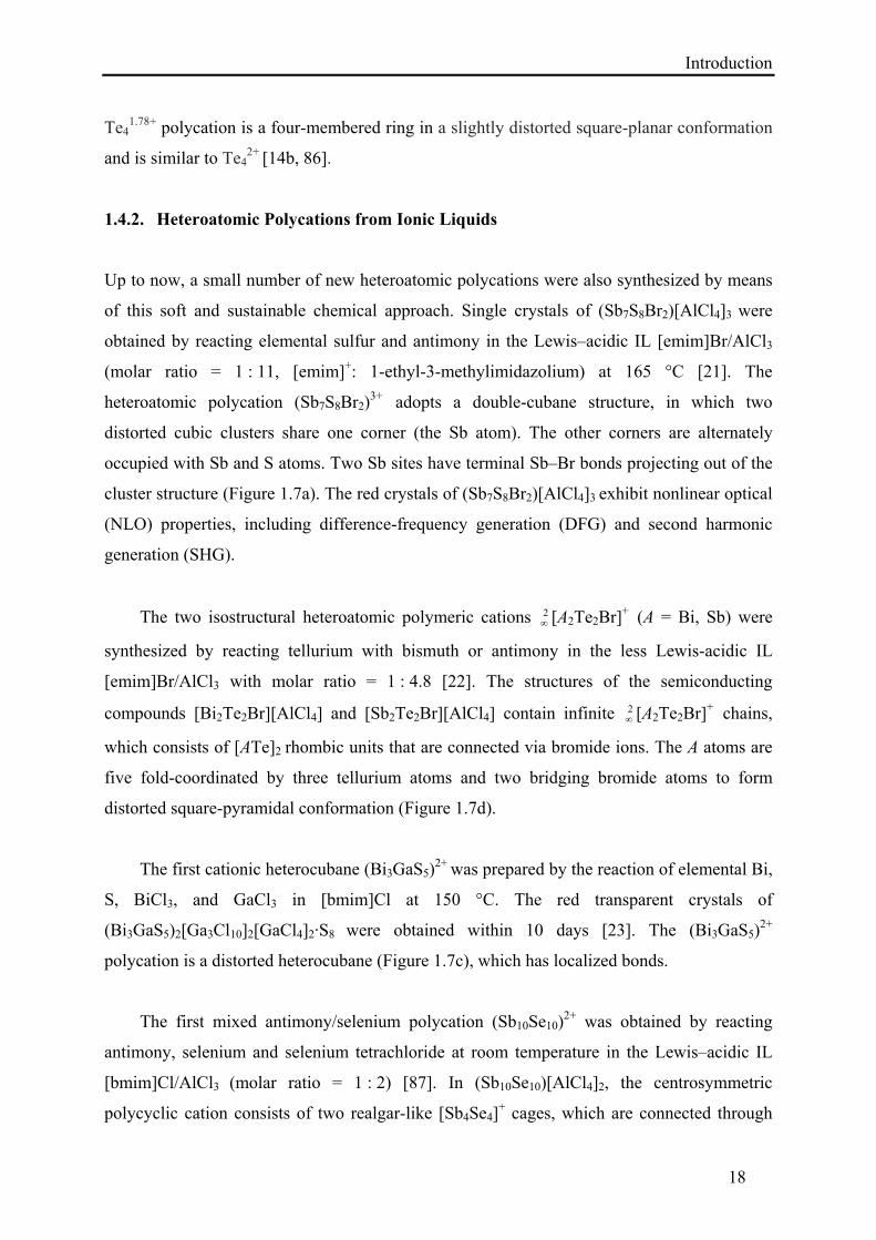
Up to now, a small number of new heteroatomic polycations were also synthesized by means
of this soft and sustainable chemical approach. Single crystals of (Sb7S8Br2)[AlCl4]3 were
obtained by reacting elemental sulfur and antimony in the Lewis–acidic IL [emim]Br/AlCl3
(molar ratio = 1 : 11, [emim]+: 1-ethyl-3-methylimidazolium) at 165 °C [21]. The
heteroatomic polycation (Sb7S8Br2)3+ adopts a double-cubane structure, in which two
distorted cubic clusters share one corner (the Sb atom). The other corners are alternately
occupied with Sb and S atoms. Two Sb sites have terminal Sb–Br bonds projecting out of the
cluster structure (Figure 1.7a). The red crystals of (Sb7S8Br2)[AlCl4]3 exhibit nonlinear optical
(NLO) properties, including difference-frequency generation (DFG) and second harmonic
generation (SHG).
The two isostructural heteroatomic polymeric cations 2 [A2Te2Br]+ (A = Bi, Sb) were
synthesized by reacting tellurium with bismuth or antimony in the less Lewis-acidic IL
[emim]Br/AlCl3 with molar ratio = 1 : 4.8 [22]. The structures of the semiconducting
compounds [Bi2Te2Br][AlCl4] and [Sb2Te2Br][AlCl4] contain infinite 2 [A2Te2Br]+ chains,
which consists of [ATe]2 rhombic units that are connected via bromide ions. The A atoms are
five fold-coordinated by three tellurium atoms and two bridging bromide atoms to form
distorted square-pyramidal conformation (Figure 1.7d).
The first cationic heterocubane (Bi3GaS5)2+ was prepared by the reaction of elemental Bi,
S, BiCl3, and GaCl3 in [bmim]Cl at 150 °C. The red transparent crystals of
(Bi3GaS5)2[Ga3Cl10]2[GaCl4]2·S8 were obtained within 10 days [23]. The (Bi3GaS5)2+
polycation is a distorted heterocubane (Figure 1.7c), which has localized bonds.
The first mixed antimony/selenium polycation (Sb10Se10)2+ was obtained by reacting
antimony, selenium and selenium tetrachloride at room temperature in the Lewis–acidic IL
[bmim]Cl/AlCl3 (molar ratio = 1 : 2) [87]. In (Sb10Se10)[AlCl4]2, the centrosymmetric
polycyclic cation consists of two realgar-like [Sb4Se4]+ cages, which are connected through
Introduction
19
three-bonded selenium atoms with the central [Sb2Se2] ring (Figure 1.7b). (Sb10Se10)2+
represents an electron-precise structure according to the Zintl concept.
Figure 1.7: The structures of the heteroatomic polycations (a) (Sb7S8Br2)3+ (b) (Sb10Se10)
2+ (c) (Bi3GaS5)2+, and
(d) an infinite layer of 2 [Bi2Te2Br]+.
The IL based low-temperature synthesis facilitated the isolation of a number of known
and new main group sub-valent compounds in high yield. This stimulated the investigation of
the physical properties. Recently, Sun and co-workers studied the photoluminescence (PL)
properties of Bi5[AlCl4]3 crystals, synthesized from IL [88a]. Bi5[AlCl4]3 exhibits extremely
broad near-infrared (NIR) PL with a full width at the half maximum (FWHM) of > 510 nm
and an effective PL lifetime of 4.1 μs at 1160 nm. They also investigated Raman and
absorption spectra of the IL containing subvalent bismuth, which confirmed the coexistence
of Bi53+ and Bi+ in the solution. The Bi5
3+ and Bi+ emitters, stabilized by the Lewis-acidic IL,
demonstrated ultrabroad NIR photoluminescence with a lifetime of around 1 μs [88b].
Additionally, this innovative facile route has proved that essentially all polycation syntheses
previously performed in molten AlCl3 can be made in IL at room temperature.
Introduction
20
Table 1.1 A list of selected homo- and heteroatomic polycations of groups 15 and 16, synthesized by different
routes.
Polycations Inorganic solvents Higher temperature synthesis
Organic solvents
Ionic liquids
O2+ [5]
S42+ [32] - - -
S82+ [37] - - -
S192+ [41] - - -
Se42+ [31] [58] - -
Se82+ [38] [39, 66] - -
Se102+ [40] [58] - -
Se172+ - [68] - -
Te42+ [33] [14b] [16a, 16b] [19]
Te41.78+ - - - [84]
Te64+ [35] - - -
Te62+ - [59a, 60] - [19]
Te72+ [36] [61] - -
Te82+ - [62–64] - [85]
Te84+ - [65] - -
Te102+ - [67] - -
N5+ [10a] - - -
Bi53+ [42] [14a, 15, 50] [16c, 76d] [17]
Bi5+ - [53] - -
Bi62+ - [53, 54] - -
Bi82+ - [14a, 50] [16b, 16c] -
Bi95+ - [6, 7, 50c, 56, 57] - [84]
Sb82+ - - [10b] -
(Te2Se2)2+,
(Te3Se)2+, and
(S3Se)2+
[43] - - -
(Te3S3)2+ and
(TexSe6–x)2+
[44] - - -
(Se4Te3)2+ - [73] - -
(Te2Se6)2+ [45] - - -
(Te4S4)2+ [46] - - -
(Te2Se8)2+ [45, 47] - - -
(As3Se4)+ and
(As3S4)+
[48a] - - -
(S4N4)2+ and (S4N5)
+ [48b, 76c] - - -
(S5N5)+ and (S6N4)
2+ [48c, 48d] - - -
(SN)+ or (SNS)+ - - [48e, 76a, 76b] -
(As3S5)+ - [74] - -
[Sb2Te2]n+ - [72] - -
(Bi4Te4)4+,
(Bi4Se4)4+, and
(Bi4Se4)4+
- [71] - -
(Bi8Si2)3+ - [51a] - -
(Pd@Bi10)4+ and
(Au@Bi10)5+
- [51b, 51c, 51e] - -
(Bi10Au2)6+ - [51d, 51f] - -
(Sb7S8Br2)3+ - - - [21]
[Bi2Te2Br]n+ and
[Sb2Te2Br]n+
- - - [22]
(Bi3GaS5)2+ - - - [23]
(Sb10Se10)2+ - - - [87]
Introduction
21
1.5. Polynuclear Transition Metal Complexes in Ionic Liquids
Ionic liquids (IL) are being applied extensively as convenient solvents for organic and
inorganic synthesis [78, 89], for crystal engineering of coordination compounds [90–96], for
liquid–liquid extraction [97], for electrodeposition [98], for spectroscopic studies [88], as
electrolyte in photovoltaic devices (solar cells) [99] and as a constituent in hybrid materials
[100]. Moreover, transition metal containing IL are regarded as potential materials that
combine the properties of IL with additional inherent magnetic, optical, or catalytic properties
that depend on the incorporated metal ion [101–105]. A significant and distinctive feature of
IL is the tunability of their chemical and physical properties by selecting an appropriate
combination of cation and anion.
There are several classical routes available to synthesize polynuclear transition metal
compounds. Mostly, they had been synthesized employing either higher temperature reactions
(crystallization from melt or CVT) [51, 70, 106] or by treating the precursors in some organic
solvents (non-polar, e.g. ether or benzene, or polar, e.g. dichloromethane or acetonitrile)
[107–109] or inorganic solvents (e.g. water or aqueous HCl) [110].
In the late 1980’s, Hussey and co-workers introduced RTIL for stabilizing both
monomeric and polymeric chlorido complexes of transition metals [111]. In many cases,
RTIL proved to be superior to conventional molecular solvents such as water or acetonitrile,
because the solvation and solvolysis pathways that are often available to these complexes in
molecular solvents are absent in RTIL. Moreover, they also managed to investigate the
spectroscopic and electrochemical properties of some of the transition metal chloride clusters
[112–114]. Later, Hughbanks et al. reported a novel procedure, using RTIL to isolate the
centered hexanuclear zirconium halogenide cluster compounds and studied their
spectroscopic, electrochemical, and structural properties [115–118]. Following the same
procedure, Köckerling et al. and Saito et al. synthesized some new centered hexanuclear
zirconium halogenide clusters and trinuclear rhenium halogenide clusters respectively [119,
120]. Mudring and co-workers synthesized a number of new salt–like structures from IL,
containing lanthanides in the anionic network and investigated their structural and physical
properties [93–96]. Dyson et al. used IL as reagent and solvent to prepare several new
organometallics. They also studied catalytic properties of transition metal carbonyl clusters in
IL [121–122]. Nockemann and co-workers obtained some polynuclear metal complexes from
Introduction
22
task specific or functionalized IL [123, 124]. With respect to the number of metal atoms
present in the structure, metal clusters or complexes are categorised and discussed.
Table 1.2 List of abbreviations for different ionic liquids.
Ionic Liquid Abbreviation
betainium bis(trifluoromethyl)sulfonylimide [Hbet][Tf2N]
1-carboxymethyl-3-methylimidazolium bis(trifluoromethyl)sulfonylimide [Hbetmim][Tf2N]
N-carboxymethyl-N-methylmorpholinium bis(trifluoromethyl)sulfonylimide [Hbetmmor][Tf2N]
N-carboxymethyl-N-methylpyrrolidinium bis(trifluoromethyl)sulfonylimide [Hbetmpyr][Tf2N]
N-butylpyridinium oxopentafluoridomolybdate [bpy]MoOF5
1-ethyl-3-methylimidazolium tetrabromidoaluminate [emim]Br/AlBr3
1-butyl-1-methylpyrrolidinium trifluoromethanesulfonate [bmpyr][OTf]
1-propyl-3-methylimidazolium bis(trifluoromethyl)sulfonylimide [C3mim][Tf2N]
1-butyl-3-methylpyrrolidinium bis(trifluoromethyl)sulfonylimide [C4mpyr][Tf2N]
1.5.1. Binuclear Complexes
Nockemann and co-workers developed carboxyl-functionalized IL that are able to dissolve
considerable amounts of a wide range of metal oxides, including rare-earth oxides. Such IL
are of particular interest for applications in the nuclear fuel cycle, namely, for the extraction
of uranium from ores and for the processing of spent nuclear fuel rods [123–126]. Nockemann
et al. reported different metal complexes formed upon dissolution of corresponding metal
oxides and hydroxides in different IL, functionalized with a carboxyl group, e.g.
[Hbet][Tf2N], [Hbetmim][Tf2N], [Hbetmmor][Tf2N] and [Hbetmpyr][Tf2N]. X-ray diffraction
studies on single crystals of the metal complexes revealed a rich structural variety with strong
dependence on the cationic core attached to the carboxylate groups. The task specific
betainium IL produced a number of polynuclear complexes. All these complexes were
incorporated with zwitterionic carboxylate ligands and [Tf2N]– counterions. Besides, the
structural determination of single crystals of the complexes crystallized from these IL, the
measurement of absorption and luminescence spectra of the metal complexes were also
carried out. Task specific IL were used to synthesize different binuclear complexes, e.g.
[(UO2)2(bet)6(H2O)2][Tf2N]4, [Cu2(betmmor)4][Tf2N]4, [Eu2(betmmor)6(H2O)2][Tf2N]6,
[Cu2(betmpyr)4(H2O)2][Tf2N]4, [Eu2(bet)8(H2O)4][Tf2N]6, [Cu2(betmim)4(H2O)2][Tf2N]4·H2O,
[Cd2(betpy)2(H2O)2][Tf2N]2, [Eu2(bet)8(H2O)2][Tf2N]6·2H2O, or [Y2(bet)6(H2O)4][Tf2N]6
[123, 124].
The crystal structure of binuclear complex [(UO2)2(bet)6(H2O)2][Tf2N]4 consists of the
binuclear complex cation [(UO2)2(bet)6]4+ with six coordinating betaine zwitterions and two
Introduction
23
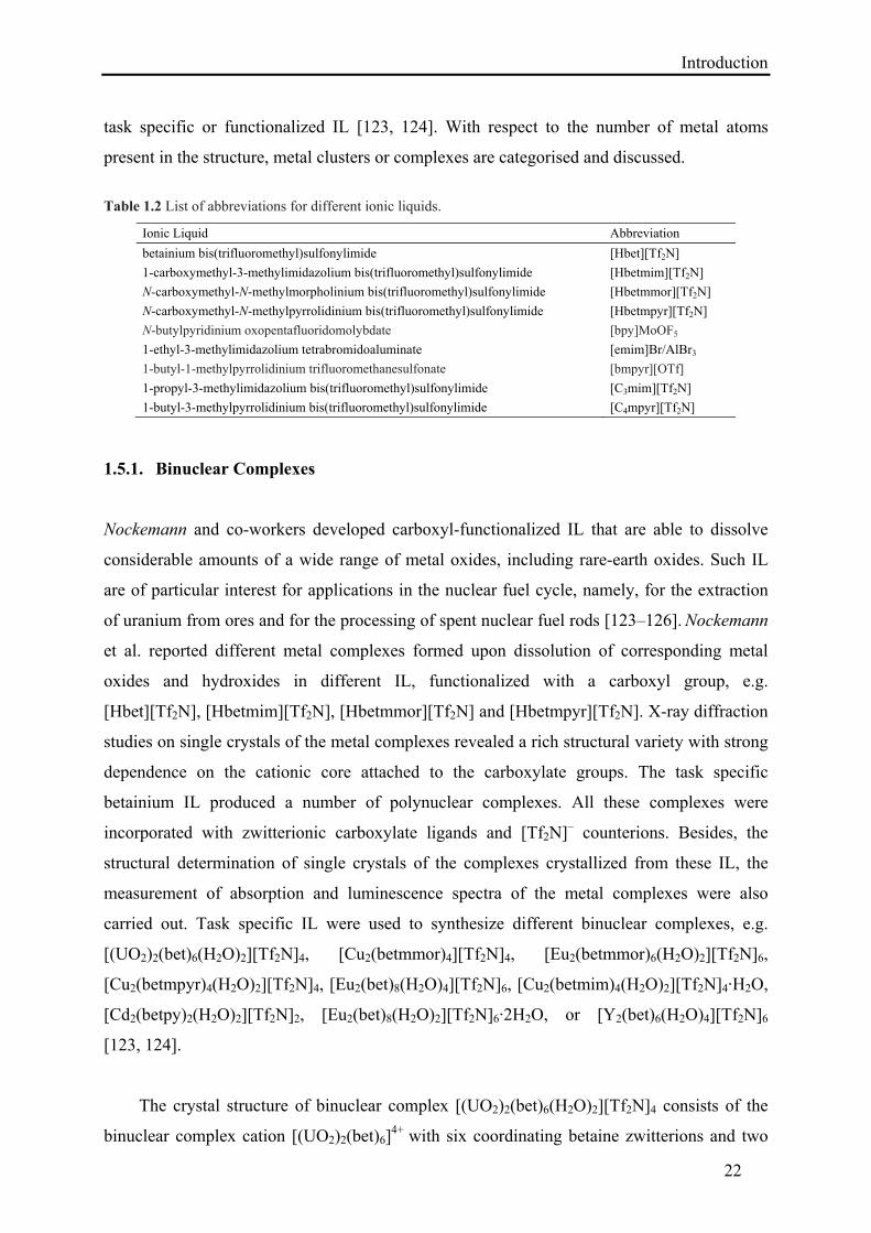
water molecules, surrounded by four non-coordinating bistriflimide [Tf2N]– counterions
(Figure 1.8).
Figure 1.8: The binuclear [(UO2)2(bet)6(H2O)2]4+ complex cation. Hydrogen atoms are omitted for clarity as in
the following Figures.
Two of the carboxyl functionalized betaine zwitterions are μ2-bridging. The other four
betaine zwitterions exhibit monodentate coordination to each of the two uranyl cations in the
asymmetric unit. Four of the coordinating betaine ligands and one water molecule form
slightly distorted pentagonal bipyramidal oxygen coordination around each of the
uranium(VI) atoms [124a]. Spectroscopic studies revealed that the uranyl complex was
decomposed in aqueous solution, while in acetonitrile and in the IL [Hbet][Tf2N], the
carboxylate groups remained coordinated.
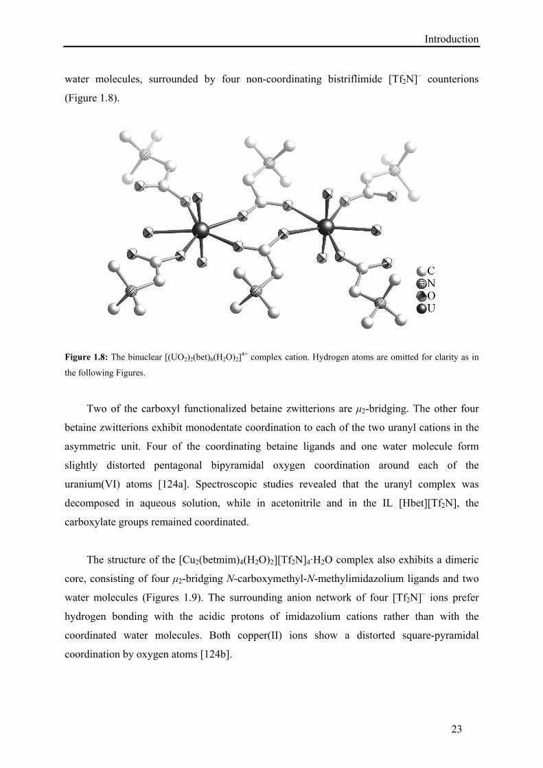
The structure of the [Cu2(betmim)4(H2O)2][Tf2N]4·H2O complex also exhibits a dimeric
core, consisting of four μ2-bridging N-carboxymethyl-N-methylimidazolium ligands and two
water molecules (Figures 1.9). The surrounding anion network of four [Tf2N]– ions prefer
hydrogen bonding with the acidic protons of imidazolium cations rather than with the
coordinated water molecules. Both copper(II) ions show a distorted square-pyramidal
coordination by oxygen atoms [124b].
Introduction
24
Figure 1.9: The binuclear [Cu2(betmim)4(H2O)2]4+ complex cation.
Recently, Hagiwara et al. reported the binuclear molybdenum complex
[bpy]2[Mo2O4F6]. It was obtained in an attempt to crystallize the low-melting salt bpyMoOF5,
but single crystals of [bpy]2[Mo2O4F6] resulted from the hydrolysis of bpyMoOF5 with some
traces of water during the crystal growth [127].
1.5.2. Trinuclear Complexes
Saito et al. synthesized a trinuclear rhenium sulfide cluster from Lewis basic IL by treating
Re3S7Cl7 with a 1:1 mixture of emimBr and AlBr3 at 70 °C for 2 days followed by refluxing
in acetonitrile to get a viscous solution. After cooling and filtration, diethyl ether was layered
and a black solid was obtained, which was recrystallized from acetonitrile/diethyl ether to get
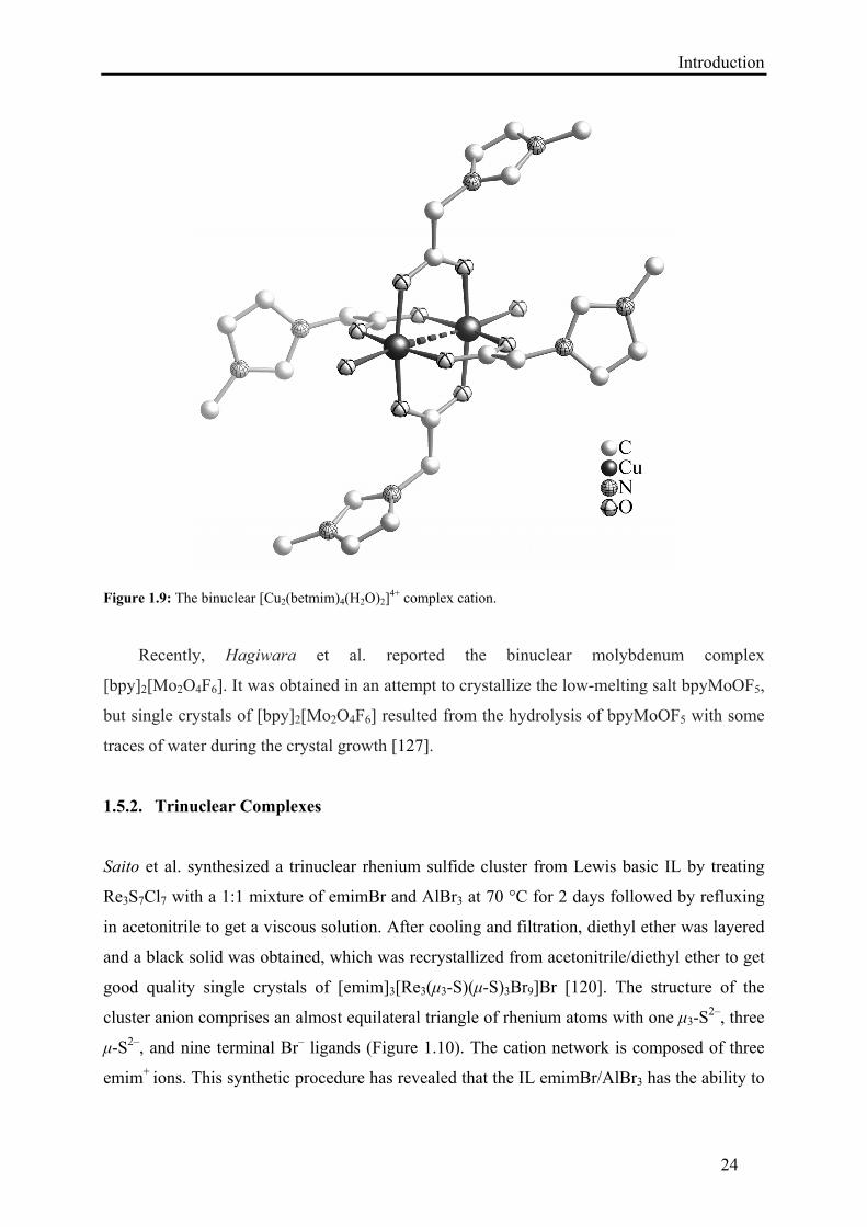
good quality single crystals of [emim]3[Re3(μ3-S)(μ-S)3Br9]Br [120]. The structure of the
cluster anion comprises an almost equilateral triangle of rhenium atoms with one μ3-S2–, three
μ-S2–, and nine terminal Br– ligands (Figure 1.10). The cation network is composed of three
emim+ ions. This synthetic procedure has revealed that the IL emimBr/AlBr3 has the ability to
Introduction
25
remove one of the S atoms in the μ-S22– ligands of the precursor complex [Re3(μ3-S)(μ-
S2)3Cl6]Cl, to exchange Cl– for Br–, and to coordinate extra bromido ligands to the Re3S4 core.
Figure 1.10: Left: The [Re3(μ3-S)(μ-S)3Br9]2– cluster anion, Right: Polyhedra representation emphasizing the
edge-sharing of coordination octahedra.
Nockemann and co-workers demonstrated the preparation of the trinuclear cobalt
complex [Co3(bet)8(Hbet)2(H2O)2][Tf2N]10[Hbet]2 from the task specific IL [Hbet][Tf2N]
[123a]. The synthesis was accomplished by reacting Co(OH)2 with [Hbet][Tf2N] in the
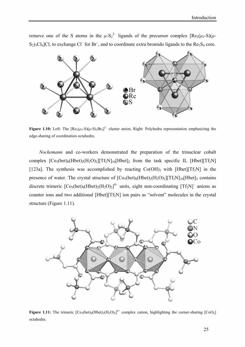
presence of water. The crystal structure of [Co3(bet)8(Hbet)2(H2O)2][Tf2N]10[Hbet]2 contains
discrete trimeric [Co3(bet)8(Hbet)2(H2O)2]8+ units, eight non-coordinating [Tf2N]– anions as
counter ions and two additional [Hbet][Tf2N] ion pairs as “solvent” molecules in the crystal
structure (Figure 1.11).
Figure 1.11: The trimeric [Co3(bet)8(Hbet)2(H2O)2]8+ complex cation, highlighting the corner-sharing [CoO6]
octahedra.
Introduction
26
The three cobalt(II) atoms of the trimeric [Co3(bet)8(Hbet)2(H2O)2]8+ units are connected by
four μ2-bridging carboxylate groups of the betaine ligands and two bridging water molecules.
The octahedral oxygen coordination of each cobalt atom is slightly distorted (Figure 1.11).
1.5.3. Tetranuclear Complexes
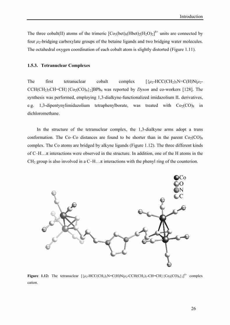
The first tetranuclear cobalt complex [{μ2-HCC(CH2)3N=C(H)N(μ2-
CCH(CH2)3CH=CH}{Co2(CO)6}2]BPh4 was reported by Dyson and co-workers [128]. The
synthesis was performed, employing 1,3-dialkyne-functionalized imidazolium IL derivatives,
e.g. 1,3-dipentynylimidazolium tetraphenylborate, was treated with Co2(CO)8 in
dichloromethane.
In the structure of the tetranuclear complex, the 1,3-dialkyne arms adopt a trans
conformation. The Co–Co distances are found to be shorter than in the parent Co2(CO)8
complex. The Co atoms are bridged by alkyne ligands (Figure 1.12). The three different kinds
of C–H…π interactions were observed in the structure. In addition, one of the H atoms in the
CH2 group is also involved in a C–H…π interactions with the phenyl ring of the counterion.
Figure 1.12: The tetranuclear [{μ2-HCC(CH2)3N=C(H)N(μ2-CCH(CH2)3-CH=CH}{Co2(CO)6}2]4+ complex
cation.
Introduction
27
Nockemann et al. synthesized two tetranuclear complexes, [Mn4(bet)10(H2O)4][Tf2N]8
and [Zn4(bet)10(H2O)2][Tf2N]8, by applying the task specific IL [Hbet][Tf2N] [123a]. The
synthesis was performed by reacting the corresponding metal oxides with [Hbet][Tf2N] in the
presence of water.
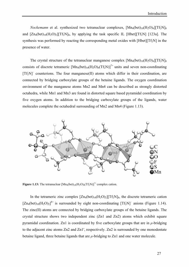
The crystal structure of the tetranuclear manganese complex [Mn4(bet)10(H2O)4][Tf2N]8
consists of discrete tetrameric [Mn4(bet)10(H2O)4(Tf2N)]7+ units and seven non-coordinating
[Tf2N]– counterions. The four manganese(II) atoms which differ in their coordination, are
connected by bridging carboxylate groups of the betaine ligands. The oxygen coordination
environment of the manganese atoms Mn2 and Mn4 can be described as strongly distorted
octahedra, while Mn1 and Mn3 are found in distorted square based pyramidal coordination by
five oxygen atoms. In addition to the bridging carboxylate groups of the ligands, water
molecules complete the octahedral surrounding of Mn2 and Mn4 (Figure 1.13).
Figure 1.13: The tetranuclear [Mn4(bet)10(H2O)4(Tf2N)]7+ complex cation.
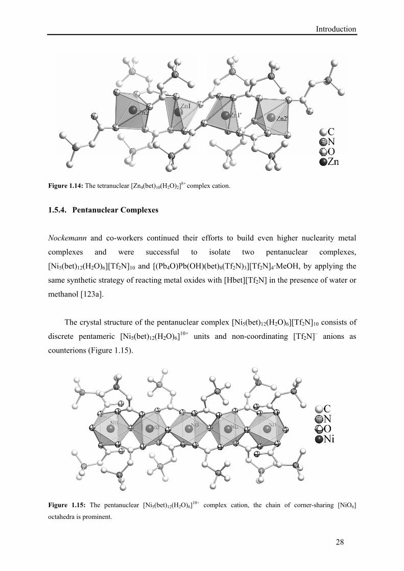
In the tetrameric zinc complex [Zn4(bet)10(H2O)2][Tf2N]8, the discrete tetrameric cation
[Zn4(bet)10(H2O)2]8+ is surrounded by eight non-coordinating [Tf2N]– anions (Figure 1.14).
The zinc(II) atoms are connected by bridging carboxylate groups of the betaine ligands. The
crystal structure shows two independent zinc (Zn1 and Zn2) atoms which exhibit square
pyramidal coordination. Zn1 is coordinated by five carboxylate groups that are in μ-bridging
to the adjacent zinc atoms Zn2 and Zn1′, respectively. Zn2 is surrounded by one monodentate
betaine ligand, three betaine ligands that are μ-bridging to Zn1 and one water molecule.
Introduction
28
Figure 1.14: The tetranuclear [Zn4(bet)10(H2O)2]
8+ complex cation.
1.5.4. Pentanuclear Complexes
Nockemann and co-workers continued their efforts to build even higher nuclearity metal
complexes and were successful to isolate two pentanuclear complexes,
[Ni5(bet)12(H2O)6][Tf2N]10 and [(Pb4O)Pb(OH)(bet)8(Tf2N)3][Tf2N]4·MeOH, by applying the
same synthetic strategy of reacting metal oxides with [Hbet][Tf2N] in the presence of water or
methanol [123a].
The crystal structure of the pentanuclear complex [Ni5(bet)12(H2O)6][Tf2N]10 consists of
discrete pentameric [Ni5(bet)12(H2O)6]10+ units and non-coordinating [Tf2N]– anions as
counterions (Figure 1.15).
Figure 1.15: The pentanuclear [Ni5(bet)12(H2O)6]
10+ complex cation, the chain of corner-sharing [NiO6]
octahedra is prominent.
Introduction
29
The three symmetrically independent nickel(II) atoms of the pentameric
[Ni5(bet)12(H2O)6]10+ unit are connected by eight μ2-bridging carboxylate groups of the
betaine ligands and four bridging water molecules. Each Ni atom is coordinated by oxygen
atoms of four betaine ligands and two water molecules to give slightly distorted octahedral
coordination polyhedron. The terminal betaine ligands and water molecules are coordinated to
Ni1 atoms in a monodentate fashion (Figure 1.15).
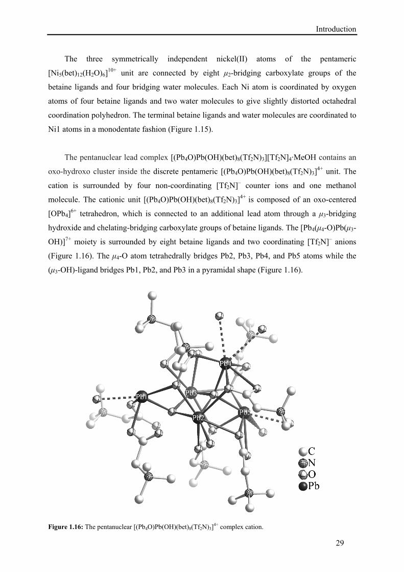
The pentanuclear lead complex [(Pb4O)Pb(OH)(bet)8(Tf2N)3][Tf2N]4·MeOH contains an
oxo-hydroxo cluster inside the discrete pentameric [(Pb4O)Pb(OH)(bet)8(Tf2N)3]4+ unit. The
cation is surrounded by four non-coordinating [Tf2N]– counter ions and one methanol
molecule. The cationic unit [(Pb4O)Pb(OH)(bet)8(Tf2N)3]4+ is composed of an oxo-centered
[OPb4]6+ tetrahedron, which is connected to an additional lead atom through a μ3-bridging
hydroxide and chelating-bridging carboxylate groups of betaine ligands. The [Pb4(μ4-O)Pb(μ3-
OH)]7+ moiety is surrounded by eight betaine ligands and two coordinating [Tf2N]– anions
(Figure 1.16). The μ4-O atom tetrahedrally bridges Pb2, Pb3, Pb4, and Pb5 atoms while the
(μ3-OH)-ligand bridges Pb1, Pb2, and Pb3 in a pyramidal shape (Figure 1.16).
Figure 1.16: The pentanuclear [(Pb4O)Pb(OH)(bet)8(Tf2N)3]
4+ complex cation.
Introduction
30
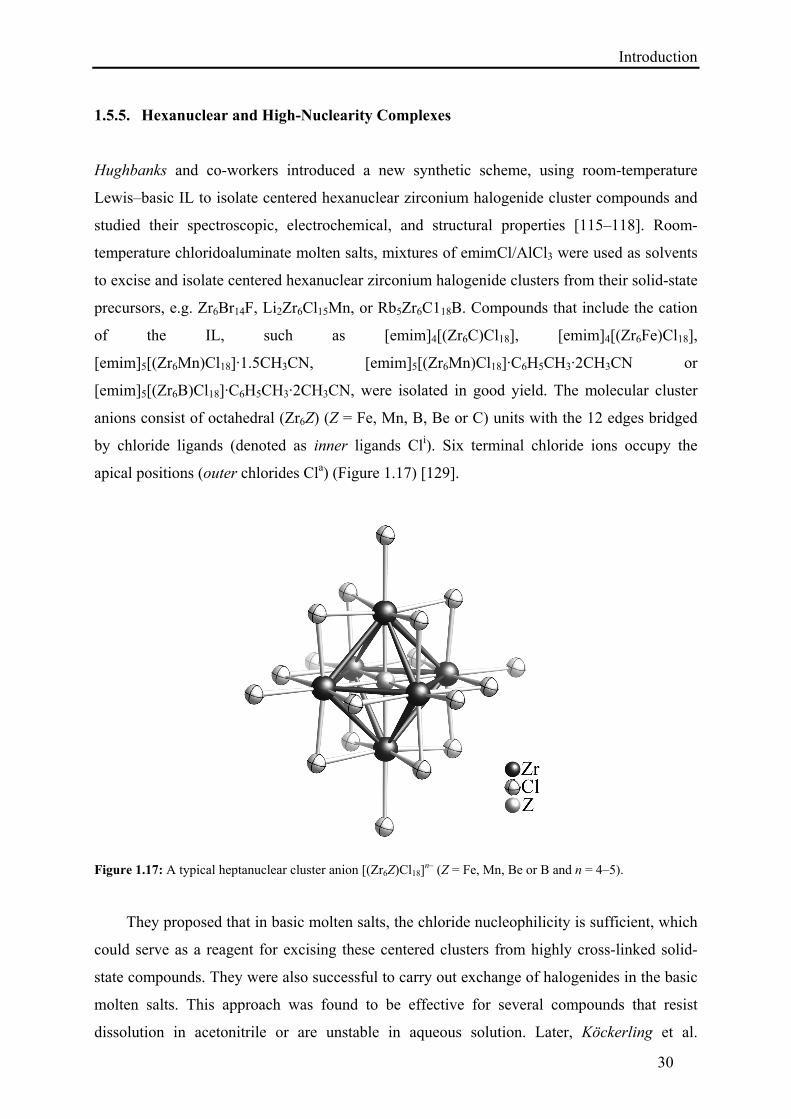
1.5.5. Hexanuclear and High-Nuclearity Complexes
Hughbanks and co-workers introduced a new synthetic scheme, using room-temperature
Lewis–basic IL to isolate centered hexanuclear zirconium halogenide cluster compounds and
studied their spectroscopic, electrochemical, and structural properties [115–118]. Room-
temperature chloridoaluminate molten salts, mixtures of emimCl/AlCl3 were used as solvents
to excise and isolate centered hexanuclear zirconium halogenide clusters from their solid-state
precursors, e.g. Zr6Br14F, Li2Zr6Cl15Mn, or Rb5Zr6C118B. Compounds that include the cation
of the IL, such as [emim]4[(Zr6C)Cl18], [emim]4[(Zr6Fe)Cl18],
[emim]5[(Zr6Mn)Cl18]·1.5CH3CN, [emim]5[(Zr6Mn)Cl18]·C6H5CH3·2CH3CN or
[emim]5[(Zr6B)Cl18]·C6H5CH3·2CH3CN, were isolated in good yield. The molecular cluster
anions consist of octahedral (Zr6Z) (Z = Fe, Mn, B, Be or C) units with the 12 edges bridged
by chloride ligands (denoted as inner ligands Cli). Six terminal chloride ions occupy the
apical positions (outer chlorides Cla) (Figure 1.17) [129].
Figure 1.17: A typical heptanuclear cluster anion [(Zr6Z)Cl18]n– (Z = Fe, Mn, Be or B and n = 4–5).
They proposed that in basic molten salts, the chloride nucleophilicity is sufficient, which
could serve as a reagent for excising these centered clusters from highly cross-linked solid-
state compounds. They were also successful to carry out exchange of halogenides in the basic
molten salts. This approach was found to be effective for several compounds that resist
dissolution in acetonitrile or are unstable in aqueous solution. Later, Köckerling et al.
Introduction
31
followed the same route and isolated cluster phases [emim]4[(Zr6Fe)Br18] and
[emim]4[(Zr6Be)Br18] from their solid-state precursors Na4[(Zr6Be)Cl16] and K[(Zr6Fe)Cl15]
by dissolving in Lewis basic emimBr/AlBr3. In the bromide based IL, a complete exchange of
all the outer and inner chlorides by bromide took place [119].
Mudring and co-workers isolated a number of new salt-like structures from IL,
containing lanthanides in the anion network. Besides mononuclear complexes [93, 95], they
also synthesized an octanuclear europium cluster compound [bmpyr]6[Eu8(μ4-O)(μ3-OH)12(μ2-
OTf)14(μ-OTf)2]·(HOTf)1.5 from the IL [bmpyr][OTf]. The structural characterization revealed
an Eu8 cluster unit, which is centered by an oxide anion [96]. Moreover, they also prepared
some low melting IL, e.g. [C3mim][Eu(Tf2N)4] (melting point = 81.0 °C),
[C4mim][Eu(Tf2N)4] (melting point = 67.9 °C), and [C4mpyr]2[Eu(Tf2N)5] (melting point =
92.1 °C). The dimeric europium units of the composition [Eu2(Tf2N)8]2– were confirmed in
the first two substances through crystallographic studies. These low melting IL possess
excellent photophysical properties (high lifetimes at high europium(III) concentration, small
linewidth, and high color purity), which might render them particularly valuable for various
optical applications [94a].
IL with polyoxometallate (POM) anions are also known. The first POM-based IL was
reported by Giannelis et al [130]. The synthesis was performed by combining a partially
deprotonated heteropolyacid [H3–xPW12O40]x– with quaternary ammonium ions
(CH3)(C18H37)N+[(CH2CH2O)nH][(CH2CH2O)mH] (m + n = 15). This new family of materials
was characterized by electrochemical and thermal analysis. The fluid character and proton
transport properties under anhydrous conditions make these IL possible candidates for fuel
cell and catalytic applications. Later, Dietz et al. carried out further investigations for the
preparation and preliminary characterization of the other members of this family of aprotic,
POM-based IL, and described their potential as organic-inorganic hybrid materials [131]. Hou
et al. and many other promoted this class of materials by adding IL to the list that exhibited
excellent catalytic performance in organic synthesis [132–136].
Shan et al. synthesized several new inorganic IL [137] consisting of an inorganic
polyoxometalate anion with the Keggin structure and sodium cations, e.g.
Na13[Ln(TiW11O39)2]·xH2O (Ln = La, Ce, Pr, Sm, Gd, Dy, Er, Tm, or Yb, x = 27.1–43.7),
Na5[MTiW11O39]·xH2O and Na6[MTiW11O39]·xH2O (M = Cr, Mn, Fe, or Zn, x = 27.2–30.2).
Introduction
32
These inorganic IL were characterized by NMR, IR spectroscopy and by elemental analysis.
Moreover, their physicochemical properties were also investigated. It was concluded that
these IL are almost immiscible with water below room temperature, but the solubility of the
IL increases sharply with an increase in temperature.
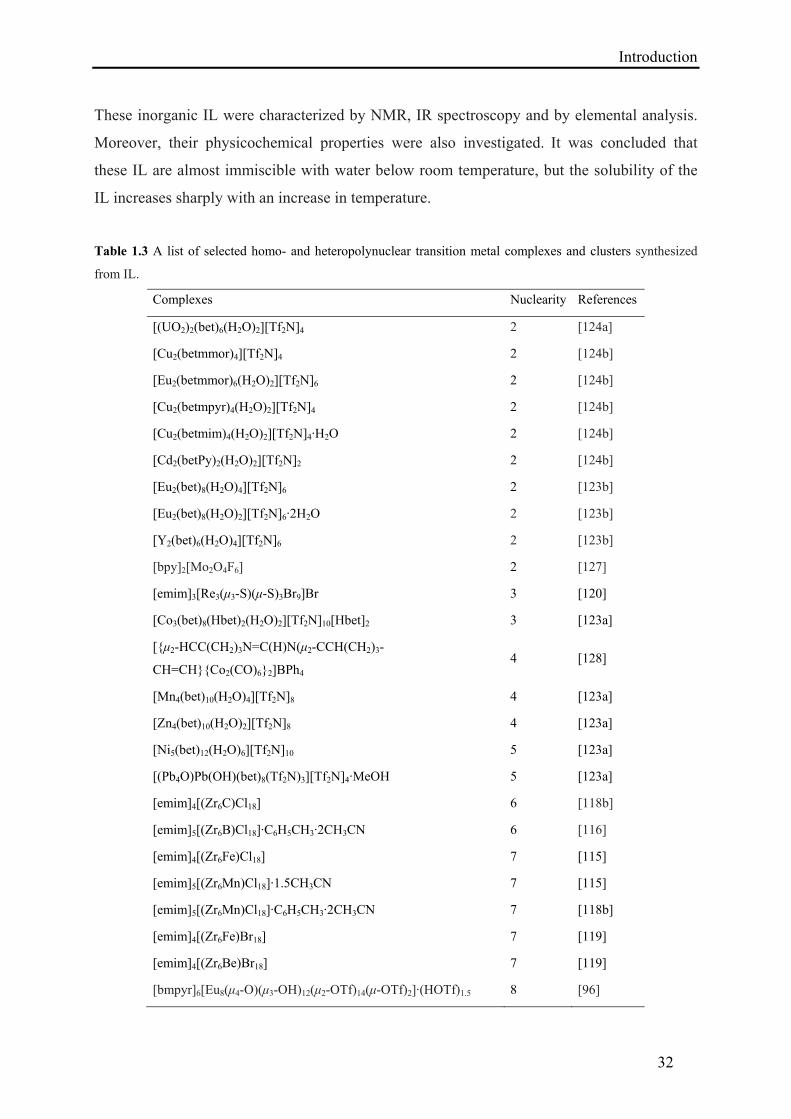
Table 1.3 A list of selected homo- and heteropolynuclear transition metal complexes and clusters synthesized
from IL.
Complexes Nuclearity References
[(UO2)2(bet)6(H2O)2][Tf2N]4 2 [124a]
[Cu2(betmmor)4][Tf2N]4 2 [124b]
[Eu2(betmmor)6(H2O)2][Tf2N]6 2 [124b]
[Cu2(betmpyr)4(H2O)2][Tf2N]4 2 [124b]
[Cu2(betmim)4(H2O)2][Tf2N]4·H2O 2 [124b]
[Cd2(betPy)2(H2O)2][Tf2N]2 2 [124b]
[Eu2(bet)8(H2O)4][Tf2N]6 2 [123b]
[Eu2(bet)8(H2O)2][Tf2N]6·2H2O 2 [123b]
[Y2(bet)6(H2O)4][Tf2N]6 2 [123b]
[bpy]2[Mo2O4F6] 2 [127]
[emim]3[Re3(μ3-S)(μ-S)3Br9]Br 3 [120]
[Co3(bet)8(Hbet)2(H2O)2][Tf2N]10[Hbet]2 3 [123a]
[{μ2-HCC(CH2)3N=C(H)N(μ2-CCH(CH2)3-
CH=CH}{Co2(CO)6}2]BPh4 4
[128]
[Mn4(bet)10(H2O)4][Tf2N]8 4 [123a]
[Zn4(bet)10(H2O)2][Tf2N]8 4 [123a]
[Ni5(bet)12(H2O)6][Tf2N]10 5 [123a]
[(Pb4O)Pb(OH)(bet)8(Tf2N)3][Tf2N]4·MeOH 5 [123a]
[emim]4[(Zr6C)Cl18] 6 [118b]
[emim]5[(Zr6B)Cl18]·C6H5CH3·2CH3CN 6 [116]
[emim]4[(Zr6Fe)Cl18] 7 [115]
[emim]5[(Zr6Mn)Cl18]·1.5CH3CN 7 [115]
[emim]5[(Zr6Mn)Cl18]·C6H5CH3·2CH3CN 7 [118b]
[emim]4[(Zr6Fe)Br18] 7 [119]
[emim]4[(Zr6Be)Br18] 7 [119]
[bmpyr]6[Eu8(μ4-O)(μ3-OH)12(μ2-OTf)14(μ-OTf)2]·(HOTf)1.5 8 [96]
Experimental
33
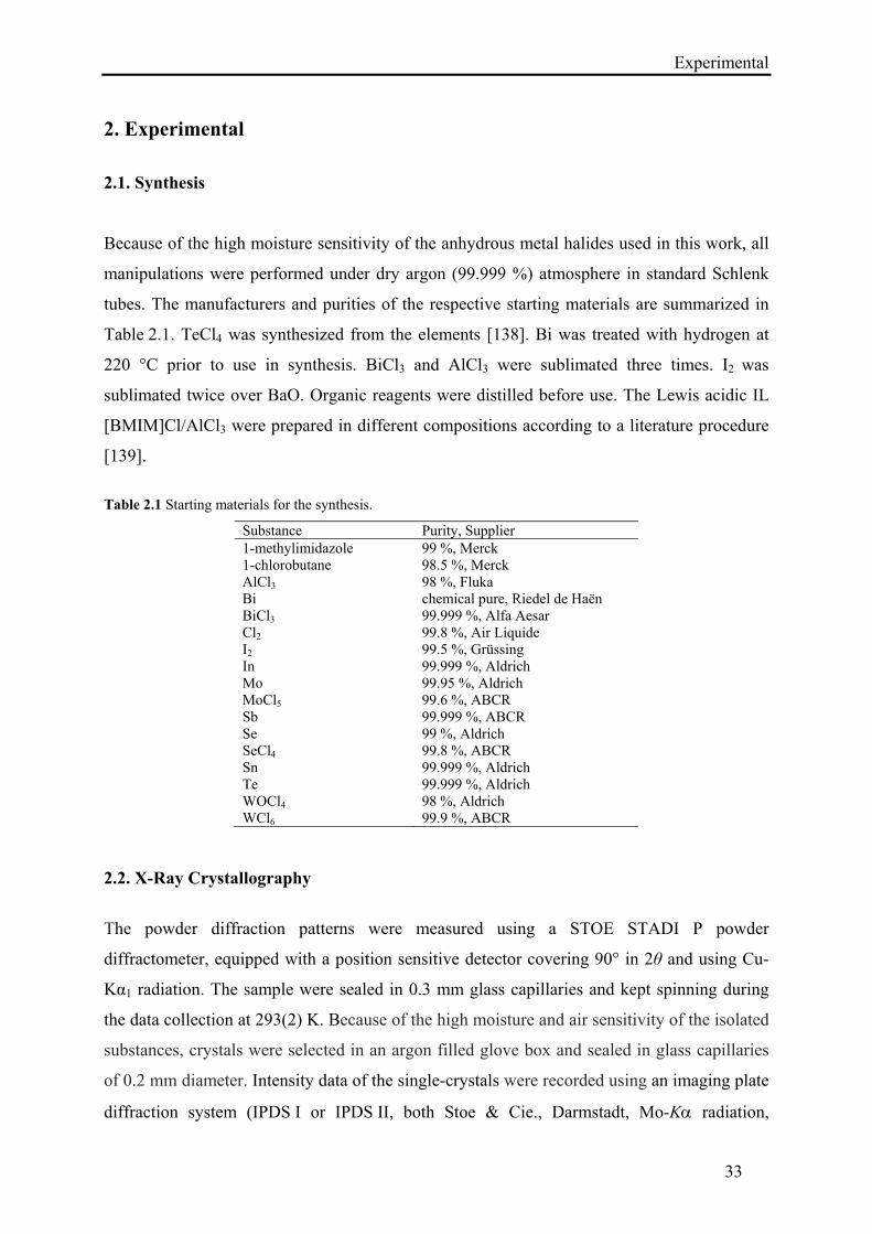
2. Experimental
2.1. Synthesis
Because of the high moisture sensitivity of the anhydrous metal halides used in this work, all
manipulations were performed under dry argon (99.999 %) atmosphere in standard Schlenk
tubes. The manufacturers and purities of the respective starting materials are summarized in
Table 2.1. TeCl4 was synthesized from the elements [138]. Bi was treated with hydrogen at
220 °C prior to use in synthesis. BiCl3 and AlCl3 were sublimated three times. I2 was
sublimated twice over BaO. Organic reagents were distilled before use. The Lewis acidic IL
[BMIM]Cl/AlCl3 were prepared in different compositions according to a literature procedure
[139].
Table 2.1 Starting materials for the synthesis.
Substance Purity, Supplier 1-methylimidazole 99 %, Merck 1-chlorobutane 98.5 %, Merck AlCl3 98 %, Fluka Bi chemical pure, Riedel de Haën BiCl3 99.999 %, Alfa Aesar Cl2 99.8 %, Air Liquide I2 99.5 %, Grüssing In 99.999 %, Aldrich Mo 99.95 %, Aldrich MoCl5 99.6 %, ABCR Sb 99.999 %, ABCR Se 99 %, Aldrich SeCl4 99.8 %, ABCR Sn 99.999 %, Aldrich Te 99.999 %, Aldrich WOCl4 98 %, Aldrich WCl6 99.9 %, ABCR
2.2. X-Ray Crystallography
The powder diffraction patterns were measured using a STOE STADI P powder
diffractometer, equipped with a position sensitive detector covering 90° in 2θ and using Cu-
Kα1 radiation. The sample were sealed in 0.3 mm glass capillaries and kept spinning during
the data collection at 293(2) K. Because of the high moisture and air sensitivity of the isolated
substances, crystals were selected in an argon filled glove box and sealed in glass capillaries
of 0.2 mm diameter. Intensity data of the single-crystals were recorded using an imaging plate
diffraction system (IPDS I or IPDS II, both Stoe & Cie., Darmstadt, Mo-K radiation,
Experimental
34
graphite monochromator) or a Bruker Kappa CCD diffractometer with graphite-
monochromatized Mo-Kα radiation at 293(2) K and at 150(2) K. The raw data were corrected
for background, polarization, and the Lorentz factor. The microscopic descriptions of the
crystal shapes, which were later used in the numerical absorption corrections [140], were
optimized using sets of symmetrically equivalent reflections [141]. The structures were solved
with direct methods and refined using SHELXL-97 [142]. Graphics of the structure were
developed using the program Diamond 3.2g [143]. The incommensurate modulated structures
of Te4[Bi0.74Cl4] was solved with the Charge Flipping algorithm [144] and refined with the
JANA2006 program package [145].
2.3. Magnetic Susceptibility Measurements
The magnetic susceptibility measurements were performed with a SQUID magnetometer
(MPMS-XL7, Quantum Design) between 1.8 K and 400 K in four different magnetic fields
between 0.20 and 70 kOe.
2.4. Raman spectroscopy
Raman spectra were recorded using Raman spectrometer (Renishaw RM-2000) equipped with
He-Ne-laser (632.8 nm). A resolution of 4.0 cm–1 was used. The single crystals were selected
in an argon filled glove box and sealed in glass capillaries of 0.2 mm diameter.
2.5. Quantum chemical calculations
Electronic structures of (Sb10Se10)[AlCl4]2 and Te4[Bi0.74Cl4] were investigated on ab initio
level of theory (DFT) utilizing the TB-LMTO-ASA [146] program. Brillouin zone
integrations were performed for (Sb10Se10)[AlCl4]2 and Te4[Bi0.74Cl4] by a tetrahedron method
using eight irreducible k-points. Scalar relativistic wave equation was solved. The Barth-
Hedin exchange potential [147a] was employed for local density approximation (LDA)
calculations, and Perdew-Wang 91 functional was utilized for generalized gradient field
(GGA) calculations [147b, 147c]. Default SCF convergence criteria of 10–6 were employed.
Band structures and density of states plots were visualized by means of Gnuplot program
package [148]. Molecular calculation were performed in the framework of DFT using
Amsterdam Density Functional (ADF) software [149], employing QZ4P basis set and BP86
Experimental
35
functional [150]. Relativistic effects were treated with ZORA formalism [151]. The starting
geometry was taken from the experimental crystal structure data. The integration and
convergence criteria were increased up to 10−8 and 10−6 respectively.
Chemical bonding was characterized by topological analysis of electron localizability
indicator (ELI, ) [152], that was performed in the DGrid 4.6 program package [153] using
the ELI-D representation according to [152]. Formal atomic charges were calculated via
integration of electron density () in basins according to the QTAIM [154]. The visualization
of results was performed in the Paraview program package [155].
The ELI-D allows for real space interpretation of chemical bonding, its gradient field can
be computed from the results of the converged quantum chemical calculations. Its maxima are
attractors, which mark out different bonding features, such as atomic electron shells, lone
electron pairs or covalent bonds. Topological analysis of the ELI-D field is performed by a
procedure similar to QTAIM, and the space is divided into basins that correspond to the
respective attractors. The integration of the basin population yields an electron count for the
particular bonding feature. The ELI-based oxidation numbers (ELIBON [156a]) are
ideologically analogous to QTAIM formal atomic charges and, for a given atom, constitute all
monosynaptic [156b] basin populations (core electrons, valence shells, lone pairs) plus the
respective share of the atom in basins with higher synapticity [156b] (pair-wise and
multicenter bonds).
ELIBON can be more accurately estimated on the basis of the polarity of the current
bond. The bond polarity index p [156c] for a two-center bond is the ratio between difference
and sum of ELI-D bond basin populations attributed to each atom by QTAIM partitioning of
ELI-D bond basin. It equals zero for a non-polar bond and unity for an ideal ionic bond. The
concept of ELIBON in its current form is not defined to partition the ELI-D basin population
for bonds with both significant covalent and ionic contributions. There are only two options:
If the bond is regarded as non-polar, then the respective ELI-D basin population is equally
distributed between all the contributing atoms upon calculation of ELIBON. If the polarity
index confirms high polarity of the bond, all respective electrons are attributed to one
constituent.
Results and Discussion
36
3. Synthesis and Characterization of Polycationic Bismuth Cluster
Compounds
3.1. Synthesis of Bi5[AlCl4]3
Stoichiometric amounts of Bi and BiCl3 (total mass = 288 mg) were added to the Lewis acidic
IL [bmim]Cl/AlCl3 (molar ratio = 1:2, volume ≈ 1.5 mL) at 298 K, which immediately turned
into a dark brown solution. The reaction mixture was left for stirring overnight at room
temperature then filtered to separate unreacted material. After three days, dark brown cubic-
shaped crystals were obtained. The excess IL was decanted in an argon filled glove box and
single crystals were separated. The crystals of the compound were washed twice with dry
dichloromethane to remove any traces of IL. Yield: 68 %.
3.2. Synthesis of Bi6Cl7
The same procedure was used as described for Bi5[AlCl4]3, starting from In and BiCl3 (total
mass = 284 mg). After two days, black needle-shaped crystals were obtained. Yield: 63 %.
The bromide analogue Bi6Br7 was also synthesized from Bi and BiBr3 using the same
methodology.
3.3. Results and Discussion
BiCl3 and bismuth reacted immediately in the Lewis acidic IL [bmim]Cl/AlCl3 at room
temperature. Within minutes after mixing, the solution turned dark brown. It is indispensable
to use Lewis acidic ionic solvents for metal cluster synthesis, because excess AlCl3 picks up
the free chloride ions from the solution to form tetrachloroaluminate ions, and these anions
stabilize the polycations. Consequently, in case of neutral or basic IL no color change was
observed. Probably the high viscosity of the reaction medium and excess Lewis acid AlCl3
facilitated the isolation of dark-red crystals of Bi5[AlCl4]3 only in three days. The addition of
some polar organic co-solvents like acetonitrile, dichloromethane and tetrahydrofuran did not
speed up crystallization. Besides the color of the solution and the precipitation of crystals,
Raman spectra (Figure 3.1) indicate the presence of bismuth polycations in the IL as well. The
Raman spectrum of bismuth polycations in solution suffered from strong fluorescence and
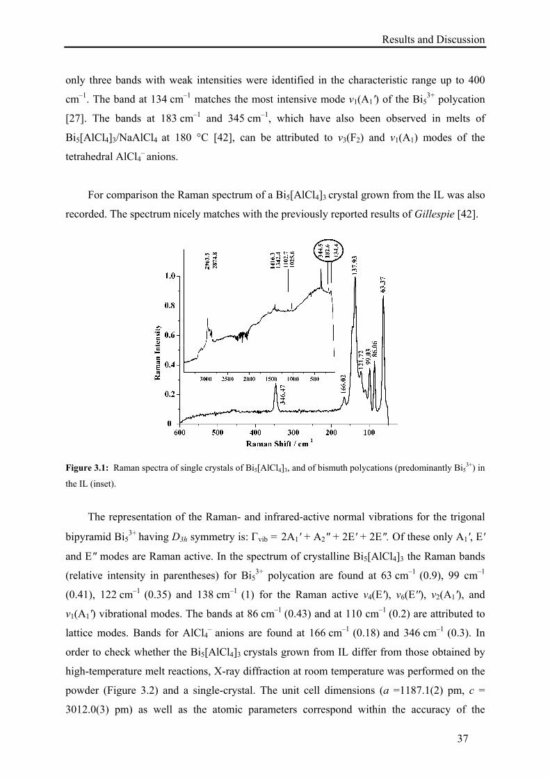
Results and Discussion
37
only three bands with weak intensities were identified in the characteristic range up to 400
cm–1. The band at 134 cm–1 matches the most intensive mode ν1(A1') of the Bi53+ polycation
[27]. The bands at 183 cm–1 and 345 cm–1, which have also been observed in melts of
Bi5[AlCl4]3/NaAlCl4 at 180 °C [42], can be attributed to ν3(F2) and ν1(A1) modes of the
tetrahedral AlCl4– anions.
For comparison the Raman spectrum of a Bi5[AlCl4]3 crystal grown from the IL was also
recorded. The spectrum nicely matches with the previously reported results of Gillespie [42].
Figure 3.1: Raman spectra of single crystals of Bi5[AlCl4]3, and of bismuth polycations (predominantly Bi53+) in
the IL (inset).
The representation of the Raman- and infrared-active normal vibrations for the trigonal
bipyramid Bi53+ having D3h symmetry is: vib = 2A1' + A2" + 2E' + 2E". Of these only A1', E'
and E" modes are Raman active. In the spectrum of crystalline Bi5[AlCl4]3 the Raman bands
(relative intensity in parentheses) for Bi53+ polycation are found at 63 cm–1 (0.9), 99 cm–1
(0.41), 122 cm–1 (0.35) and 138 cm–1 (1) for the Raman active ν4(E'), ν6(E''), ν2(A1'), and
ν1(A1') vibrational modes. The bands at 86 cm–1 (0.43) and at 110 cm–1 (0.2) are attributed to
lattice modes. Bands for AlCl4– anions are found at 166 cm–1 (0.18) and 346 cm–1 (0.3). In
order to check whether the Bi5[AlCl4]3 crystals grown from IL differ from those obtained by
high-temperature melt reactions, X-ray diffraction at room temperature was performed on the
powder (Figure 3.2) and a single-crystal. The unit cell dimensions (a =1187.1(2) pm, c =
3012.0(3) pm) as well as the atomic parameters correspond within the accuracy of the
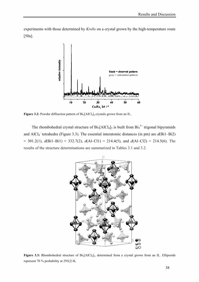
Results and Discussion
38
experiments with those determined by Krebs on a crystal grown by the high-temperature route
[50a].
Figure 3.2: Powder diffraction pattern of Bi5[AlCl4]3 crystals grown from an IL.
The rhombohedral crystal structure of Bi5[AlCl4]3 is built from Bi53+ trigonal bipyramids
and AlCl4– tetrahedra (Figure 3.3). The essential interatomic distances (in pm) are d(Bi1–Bi2)
= 301.2(1), d(Bi1–Bi1) = 332.7(2), d(Al–Cl1) = 214.4(5), and d(Al–Cl2) = 214.5(6). The
results of the structure determinations are summarized in Tables 3.1 and 3.2.
Figure 3.3: Rhombohedral structure of Bi5[AlCl4]3, determined from a crystal grown from an IL. Ellipsoids
represent 70 % probability at 293(2) K.
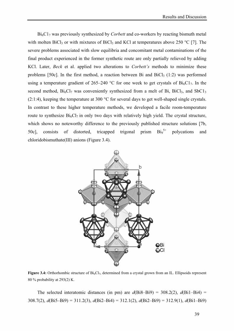
Results and Discussion
39
Bi6C17 was previously synthesized by Corbett and co-workers by reacting bismuth metal
with molten BiCl3 or with mixtures of BiCl3 and KCl at temperatures above 250 °C [7]. The
severe problems associated with slow equilibria and concomitant metal contaminations of the
final product experienced in the former synthetic route are only partially relieved by adding
KCl. Later, Beck et al. applied two alterations to Corbett’s methods to minimize these
problems [50c]. In the first method, a reaction between Bi and BiCl3 (1:2) was performed
using a temperature gradient of 265–240 °C for one week to get crystals of Bi6C17. In the
second method, Bi6Cl7 was conveniently synthesized from a melt of Bi, BiCl3, and SbC13
(2:1:4), keeping the temperature at 300 °C for several days to get well-shaped single crystals.
In contrast to these higher temperature methods, we developed a facile room-temperature
route to synthesize Bi6Cl7 in only two days with relatively high yield. The crystal structure,
which shows no noteworthy difference to the previously published structure solutions [7b,
50c], consists of distorted, tricapped trigonal prism Bi95+ polycations and
chloridobismuthate(III) anions (Figure 3.4).
Figure 3.4: Orthorhombic structure of Bi6Cl7, determined from a crystal grown from an IL. Ellipsoids represent
80 % probability at 293(2) K.
The selected interatomic distances (in pm) are d(Bi8–Bi9) = 308.2(2), d(Bi1–Bi4) =
308.7(2), d(Bi5–Bi9) = 311.2(3), d(Bi2–Bi4) = 312.1(2), d(Bi2–Bi9) = 312.9(1), d(Bi1–Bi9)
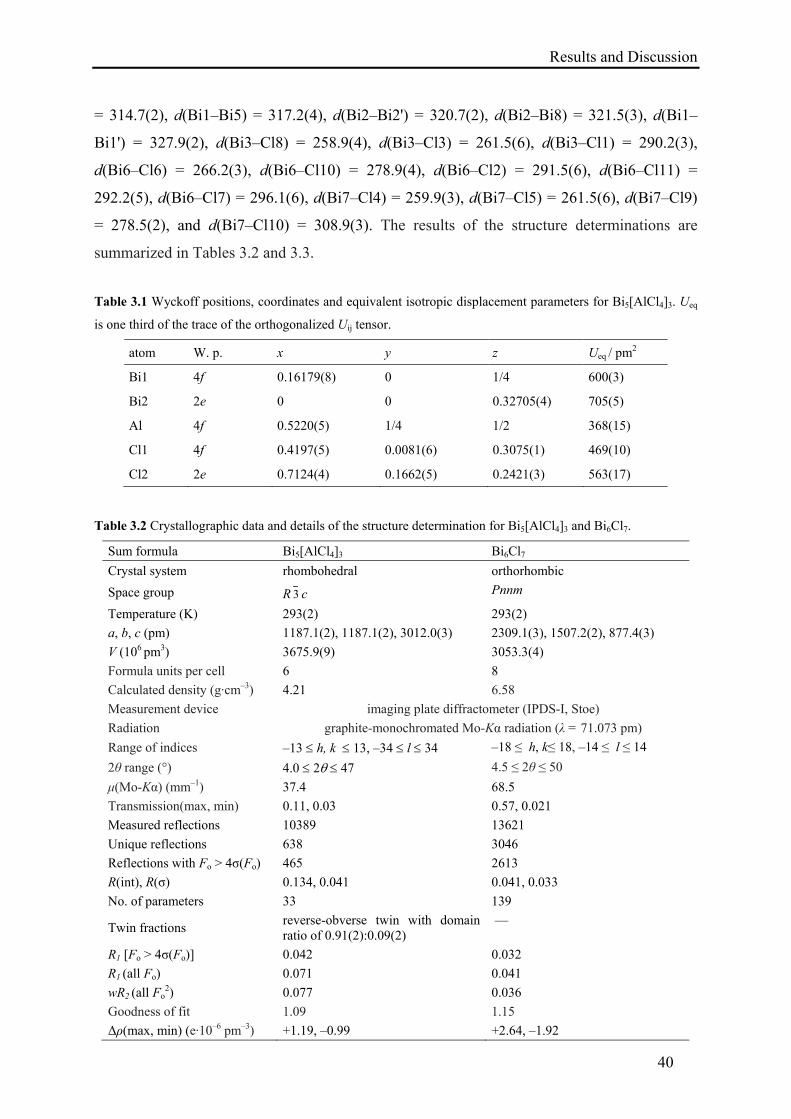
Results and Discussion
40
= 314.7(2), d(Bi1–Bi5) = 317.2(4), d(Bi2–Bi2') = 320.7(2), d(Bi2–Bi8) = 321.5(3), d(Bi1–
Bi1') = 327.9(2), d(Bi3–Cl8) = 258.9(4), d(Bi3–Cl3) = 261.5(6), d(Bi3–Cl1) = 290.2(3),
d(Bi6–Cl6) = 266.2(3), d(Bi6–Cl10) = 278.9(4), d(Bi6–Cl2) = 291.5(6), d(Bi6–Cl11) =
292.2(5), d(Bi6–Cl7) = 296.1(6), d(Bi7–Cl4) = 259.9(3), d(Bi7–Cl5) = 261.5(6), d(Bi7–Cl9)
= 278.5(2), and d(Bi7–Cl10) = 308.9(3). The results of the structure determinations are
summarized in Tables 3.2 and 3.3.
Table 3.1 Wyckoff positions, coordinates and equivalent isotropic displacement parameters for Bi5[AlCl4]3. Ueq
is one third of the trace of the orthogonalized Uij tensor.
atom W. p. x y z Ueq / pm2
Bi1 4f 0.16179(8) 0 1/4 600(3)
Bi2 2e 0 0 0.32705(4) 705(5)
Al 4f 0.5220(5) 1/4 1/2 368(15)
Cl1 4f 0.4197(5) 0.0081(6) 0.3075(1) 469(10)
Cl2 2e 0.7124(4) 0.1662(5) 0.2421(3) 563(17)
Table 3.2 Crystallographic data and details of the structure determination for Bi5[AlCl4]3 and Bi6Cl7.
Sum formula Bi5[AlCl4]3 Bi6Cl7
Crystal system rhombohedral orthorhombic
Space group R 3 c Pnnm
Temperature (K) 293(2) 293(2)
a, b, c (pm) 1187.1(2), 1187.1(2), 3012.0(3) 2309.1(3), 1507.2(2), 877.4(3)
V (106 pm3) 3675.9(9) 3053.3(4)
Formula units per cell 6 8
Calculated density (g·cm–3) 4.21 6.58
Measurement device imaging plate diffractometer (IPDS-I, Stoe)
Radiation graphite-monochromated Mo-Kα radiation (λ = 71.073 pm)
Range of indices –13 h, k 13, –34 l 34 –18 ≤ h, k≤ 18, –14 ≤ l ≤ 14
2θ range (°) 4.0 2 47 4.5 ≤ 2θ ≤ 50
μ(Mo-Kα) (mm–1) 37.4 68.5
Transmission(max, min) 0.11, 0.03 0.57, 0.021
Measured reflections 10389 13621
Unique reflections 638 3046
Reflections with Fo > 4σ(Fo) 465 2613
R(int), R(σ) 0.134, 0.041 0.041, 0.033
No. of parameters 33 139
Twin fractions reverse-obverse twin with domain ratio of 0.91(2):0.09(2)
—
R1 [Fo > 4σ(Fo)] 0.042 0.032
R1 (all Fo) 0.071 0.041
wR2 (all Fo2) 0.077 0.036
Goodness of fit 1.09 1.15
Δρ(max, min) (e·10–6 pm–3) +1.19, –0.99 +2.64, –1.92
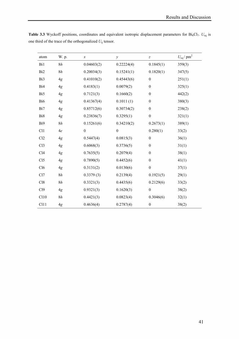
Results and Discussion
41
Table 3.3 Wyckoff positions, coordinates and equivalent isotropic displacement parameters for Bi6Cl7. Ueq is
one third of the trace of the orthogonalized Uij tensor.
atom W. p. x y z Ueq / pm2
Bi1 8h 0.04603(2) 0.22224(4) 0.1845(1) 359(3)
Bi2 8h 0.20034(3) 0.15241(1) 0.1820(1) 347(5)
Bi3 4g 0.41010(2) 0.45443(6) 0 251(1)
Bi4 4g 0.4183(1) 0.0079(2) 0 325(1)
Bi5 4g 0.7121(3) 0.1660(2) 0 442(2)
Bi6 4g 0.41367(4) 0.1011 (1) 0 380(3)
Bi7 4g 0.85712(6) 0.30734(2) 0 238(2)
Bi8 4g 0.23836(7) 0.3295(1) 0 321(1)
Bi9 8h 0.15261(6) 0.34210(2) 0.2673(1) 389(1)
Cl1 4e 0 0 0.280(1) 33(2)
Cl2 4g 0.5447(4) 0.0815(3) 0 36(1)
Cl3 4g 0.6068(3) 0.3736(5) 0 31(1)
Cl4 4g 0.7635(5) 0.2079(4) 0 38(1)
Cl5 4g 0.7890(5) 0.4452(6) 0 41(1)
Cl6 4g 0.3131(2) 0.0130(6) 0 37(1)
Cl7 8h 0.3379 (3) 0.2139(4) 0.1921(5) 29(1)
Cl8 8h 0.3321(3) 0.4435(6) 0.2129(6) 33(2)
Cl9 4g 0.9321(3) 0.1620(3) 0 38(2)
Cl10 8h 0.4421(3) 0.0823(4) 0.3046(6) 32(1)
Cl11 4g 0.4636(4) 0.2787(4) 0 38(2)
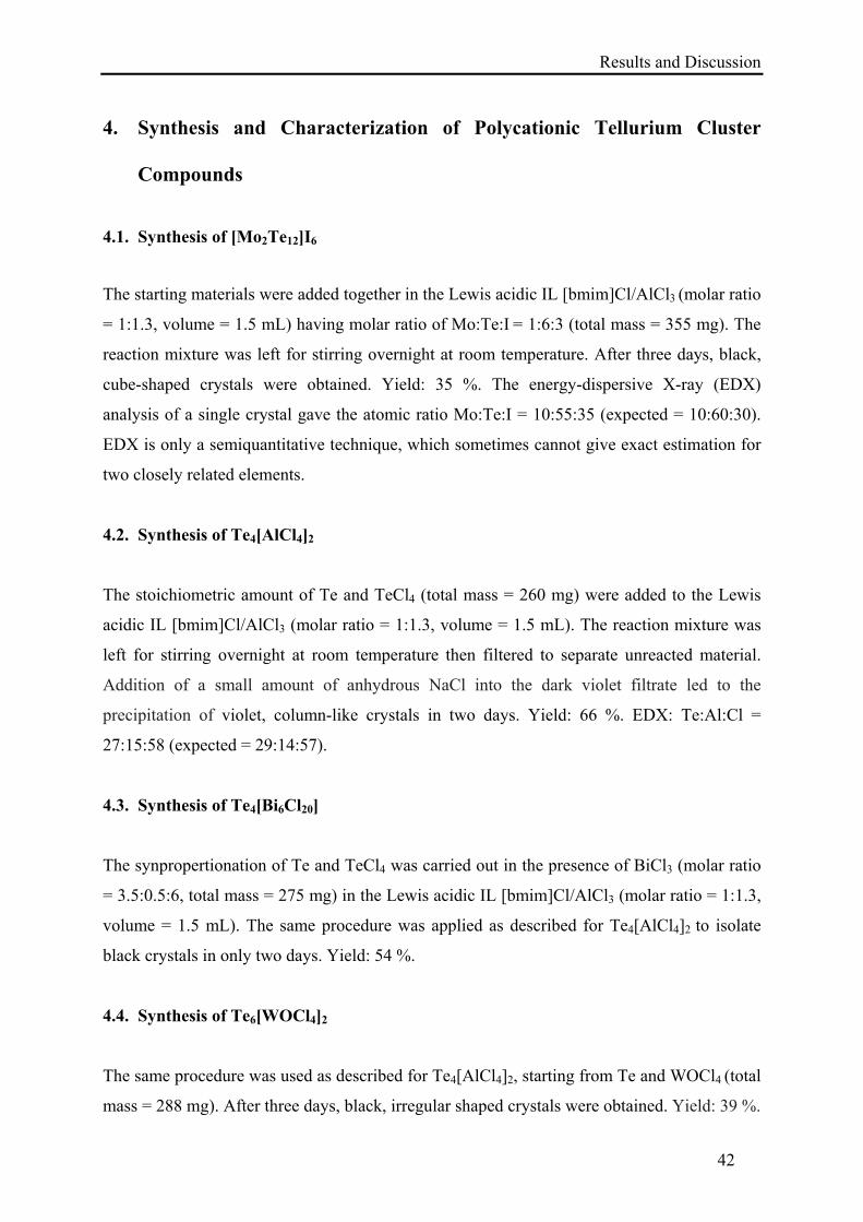
Results and Discussion
42
4. Synthesis and Characterization of Polycationic Tellurium Cluster
Compounds
4.1. Synthesis of [Mo2Te12]I6
The starting materials were added together in the Lewis acidic IL [bmim]Cl/AlCl3 (molar ratio
= 1:1.3, volume = 1.5 mL) having molar ratio of Mo:Te:I = 1:6:3 (total mass = 355 mg). The
reaction mixture was left for stirring overnight at room temperature. After three days, black,
cube-shaped crystals were obtained. Yield: 35 %. The energy-dispersive X-ray (EDX)
analysis of a single crystal gave the atomic ratio Mo:Te:I = 10:55:35 (expected = 10:60:30).
EDX is only a semiquantitative technique, which sometimes cannot give exact estimation for
two closely related elements.
4.2. Synthesis of Te4[AlCl4]2
The stoichiometric amount of Te and TeCl4 (total mass = 260 mg) were added to the Lewis
acidic IL [bmim]Cl/AlCl3 (molar ratio = 1:1.3, volume = 1.5 mL). The reaction mixture was
left for stirring overnight at room temperature then filtered to separate unreacted material.
Addition of a small amount of anhydrous NaCl into the dark violet filtrate led to the
precipitation of violet, column-like crystals in two days. Yield: 66 %. EDX: Te:Al:Cl =
27:15:58 (expected = 29:14:57).
4.3. Synthesis of Te4[Bi6Cl20]
The synpropertionation of Te and TeCl4 was carried out in the presence of BiCl3 (molar ratio
= 3.5:0.5:6, total mass = 275 mg) in the Lewis acidic IL [bmim]Cl/AlCl3 (molar ratio = 1:1.3,
volume = 1.5 mL). The same procedure was applied as described for Te4[AlCl4]2 to isolate
black crystals in only two days. Yield: 54 %.
4.4. Synthesis of Te6[WOCl4]2
The same procedure was used as described for Te4[AlCl4]2, starting from Te and WOCl4 (total
mass = 288 mg). After three days, black, irregular shaped crystals were obtained. Yield: 39 %.
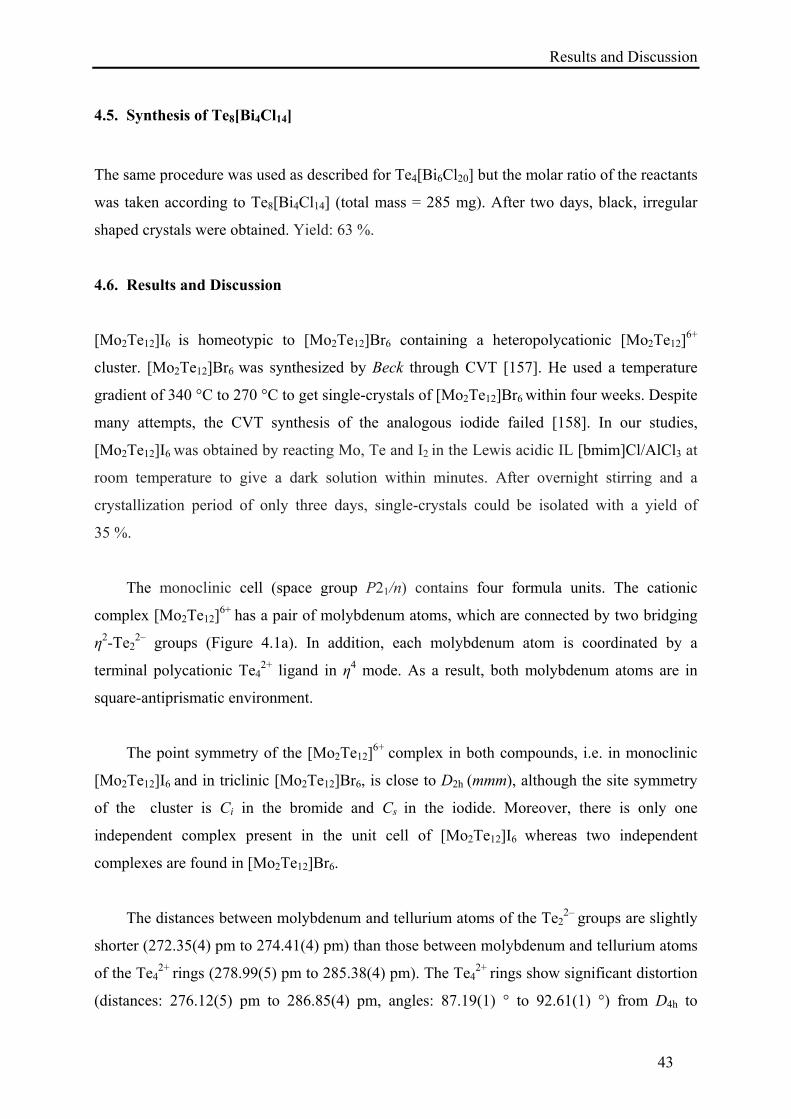
Results and Discussion
43
4.5. Synthesis of Te8[Bi4Cl14]
The same procedure was used as described for Te4[Bi6Cl20] but the molar ratio of the reactants
was taken according to Te8[Bi4Cl14] (total mass = 285 mg). After two days, black, irregular
shaped crystals were obtained. Yield: 63 %.
4.6. Results and Discussion
[Mo2Te12]I6 is homeotypic to [Mo2Te12]Br6 containing a heteropolycationic [Mo2Te12]6+
cluster. [Mo2Te12]Br6 was synthesized by Beck through CVT [157]. He used a temperature
gradient of 340 °C to 270 °C to get single-crystals of [Mo2Te12]Br6 within four weeks. Despite
many attempts, the CVT synthesis of the analogous iodide failed [158]. In our studies,
[Mo2Te12]I6 was obtained by reacting Mo, Te and I2 in the Lewis acidic IL [bmim]Cl/AlCl3 at
room temperature to give a dark solution within minutes. After overnight stirring and a
crystallization period of only three days, single-crystals could be isolated with a yield of
35 %.
The monoclinic cell (space group P21/n) contains four formula units. The cationic
complex [Mo2Te12]6+ has a pair of molybdenum atoms, which are connected by two bridging
η2-Te22– groups (Figure 4.1a). In addition, each molybdenum atom is coordinated by a
terminal polycationic Te42+ ligand in η4 mode. As a result, both molybdenum atoms are in
square-antiprismatic environment.
The point symmetry of the [Mo2Te12]6+ complex in both compounds, i.e. in monoclinic
[Mo2Te12]I6 and in triclinic [Mo2Te12]Br6, is close to D2h (mmm), although the site symmetry
of the cluster is Ci in the bromide and Cs in the iodide. Moreover, there is only one
independent complex present in the unit cell of [Mo2Te12]I6 whereas two independent
complexes are found in [Mo2Te12]Br6.
The distances between molybdenum and tellurium atoms of the Te22– groups are slightly
shorter (272.35(4) pm to 274.41(4) pm) than those between molybdenum and tellurium atoms
of the Te42+ rings (278.99(5) pm to 285.38(4) pm). The Te4
2+ rings show significant distortion
(distances: 276.12(5) pm to 286.85(4) pm, angles: 87.19(1) ° to 92.61(1) °) from D4h to
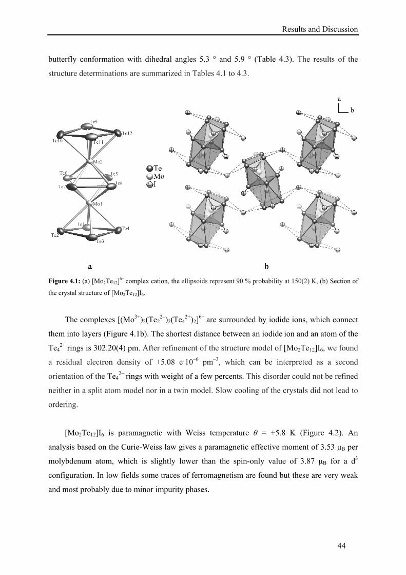
Results and Discussion
44
butterfly conformation with dihedral angles 5.3 ° and 5.9 ° (Table 4.3). The results of the
structure determinations are summarized in Tables 4.1 to 4.3.
Figure 4.1: (a) [Mo2Te12]6+ complex cation, the ellipsoids represent 90 % probability at 150(2) K, (b) Section of
the crystal structure of [Mo2Te12]I6.
The complexes [(Mo3+)2(Te22–)2(Te4
2+)2]6+ are surrounded by iodide ions, which connect
them into layers (Figure 4.1b). The shortest distance between an iodide ion and an atom of the
Te42+ rings is 302.20(4) pm. After refinement of the structure model of [Mo2Te12]I6, we found
a residual electron density of +5.08 e·10–6 pm–3, which can be interpreted as a second
orientation of the Te42+ rings with weight of a few percents. This disorder could not be refined
neither in a split atom model nor in a twin model. Slow cooling of the crystals did not lead to
ordering.
[Mo2Te12]I6 is paramagnetic with Weiss temperature θ = +5.8 K (Figure 4.2). An
analysis based on the Curie-Weiss law gives a paramagnetic effective moment of 3.53 μB per
molybdenum atom, which is slightly lower than the spin-only value of 3.87 μB for a d3
configuration. In low fields some traces of ferromagnetism are found but these are very weak
and most probably due to minor impurity phases.
Results and Discussion
45
The absence of intramolecular coupling of the magnetic cations in [Mo2Te12]I6 is
astonishing, since the short distance of 297.16(5) pm between the molybdenum(III) atoms
suggests a chemical bond. In the present case the complex is a diradical with seventeen
electrons per central atom. The electron counting scheme adds up the three valence electrons
of a molybdenum(III) atom, six electrons of the -system of the Te42+ ring, and four electrons
(two lone-pairs) of each Te22– group (3 + 6 + 4·2 = 17).
Figure 4.2: Temperature dependence of reciprocal molar susceptibility for [Mo2Te12]I6 in a magnetic field of H
= 35 kOe.
In contrast, the closely related catena-compound MoTe4Br = [(Mo3+)2(Te22–)2(Te2Br–)2]
with a Mo–Mo bond length of 300.5(2) pm shows only weak, nearly temperature-independent
paramagnetism with a magnetic moment of 0.4 μB at 310 K, indicating a strong coupling and
an eighteen electron situation [157].
Te4[AlCl4]2 was reported by Corbett and co-workers through synproportionation at
250 °C [14b]. Contrary to higher temperature method, we obtained Te4[AlCl4]2 by reacting Te
and TeCl4 in the Lewis acidic IL [bmim]Cl/AlCl3 at room temperature. Addition of a small
amount of anhydrous NaCl is helpful for getting single crystals in two days (66 % yield). The
orthorhombic compound contains planar Te42+ polycations and tetrahedral AlCl4
– anions
(Figure 4.3). The atomic coordinates agree within three standard deviations with those
published earlier (Table 4.4) [14b].
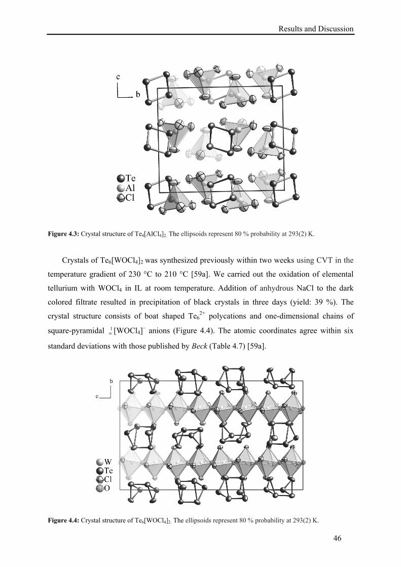
Results and Discussion
46
Figure 4.3: Crystal structure of Te4[AlCl4]2. The ellipsoids represent 80 % probability at 293(2) K.
Crystals of Te6[WOCl4]2 was synthesized previously within two weeks using CVT in the
temperature gradient of 230 °C to 210 °C [59a]. We carried out the oxidation of elemental
tellurium with WOCl4 in IL at room temperature. Addition of anhydrous NaCl to the dark
colored filtrate resulted in precipitation of black crystals in three days (yield: 39 %). The
crystal structure consists of boat shaped Te62+ polycations and one-dimensional chains of
square-pyramidal 1 [WOCl4]
– anions (Figure 4.4). The atomic coordinates agree within six
standard deviations with those published by Beck (Table 4.7) [59a].
Figure 4.4: Crystal structure of Te6[WOCl4]2. The ellipsoids represent 80 % probability at 293(2) K.
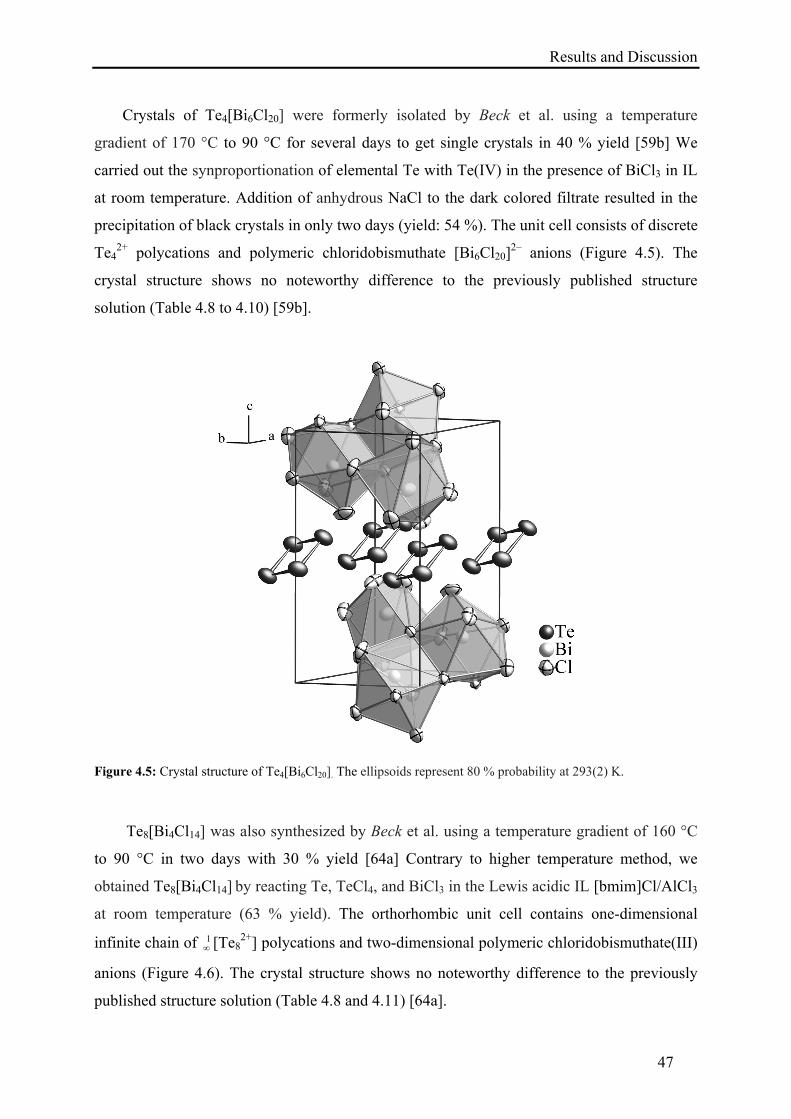
Results and Discussion
47
Crystals of Te4[Bi6Cl20] were formerly isolated by Beck et al. using a temperature
gradient of 170 °C to 90 °C for several days to get single crystals in 40 % yield [59b] We
carried out the synproportionation of elemental Te with Te(IV) in the presence of BiCl3 in IL
at room temperature. Addition of anhydrous NaCl to the dark colored filtrate resulted in the
precipitation of black crystals in only two days (yield: 54 %). The unit cell consists of discrete
Te42+ polycations and polymeric chloridobismuthate [Bi6Cl20]
2– anions (Figure 4.5). The
crystal structure shows no noteworthy difference to the previously published structure
solution (Table 4.8 to 4.10) [59b].
Figure 4.5: Crystal structure of Te4[Bi6Cl20]. The ellipsoids represent 80 % probability at 293(2) K.
Te8[Bi4Cl14] was also synthesized by Beck et al. using a temperature gradient of 160 °C
to 90 °C in two days with 30 % yield [64a] Contrary to higher temperature method, we
obtained Te8[Bi4Cl14] by reacting Te, TeCl4, and BiCl3 in the Lewis acidic IL [bmim]Cl/AlCl3
at room temperature (63 % yield). The orthorhombic unit cell contains one-dimensional
infinite chain of 1 [Te8
2+] polycations and two-dimensional polymeric chloridobismuthate(III)
anions (Figure 4.6). The crystal structure shows no noteworthy difference to the previously
published structure solution (Table 4.8 and 4.11) [64a].
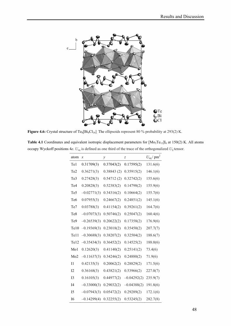
Results and Discussion
48
Figure 4.6: Crystal structure of Te8[Bi4Cl14]. The ellipsoids represent 80 % probability at 293(2) K.
Table 4.1 Coordinates and equivalent isotropic displacement parameters for [Mo2Te12]I6 at 150(2) K. All atoms
occupy Wyckoff positions 4e. Ueq is defined as one third of the trace of the orthogonalized Uij tensor.
atom x y z Ueq / pm2
Te1 0.31709(3) 0.37043(2) 0.17595(2) 131.6(6)
Te2 0.36271(3) 0.38843 (2) 0.35915(2) 146.1(6)
Te3 0.27428(3) 0.54712 (2) 0.32742(2) 155.6(6)
Te4 0.20828(3) 0.52383(2) 0.14798(2) 155.9(6)
Te5 –0.02771(3) 0.34316(2) 0.10664(2) 155.7(6)
Te6 0.07955(3) 0.24667(2) 0.24851(2) 145.1(6)
Te7 0.03788(3) 0.41154(2) 0.39261(2) 164.7(6)
Te8 –0.07073(3) 0.50746(2) 0.25047(2) 160.4(6)
Te9 –0.26539(3) 0.20622(2) 0.17358(2) 176.9(6)
Te10 –0.19369(3) 0.23018(2) 0.35450(2) 207.7(7)
Te11 –0.30688(3) 0.38207(2) 0.32504(2) 188.6(7)
Te12 –0.35434(3) 0.36452(2) 0.14525(2) 188.0(6)
Mo1 0.12620(3) 0.41140(2) 0.25141(2) 73.4(6)
Mo2 –0.11637(3) 0.34246(2) 0.24880(2) 71.9(6)
I1 0.42135(3) 0.20062(2) 0.28829(2) 171.5(6)
I2 0.36168(3) 0.43821(2) 0.53966(2) 227.0(7)
I3 0.16105(3) 0.44977(2) –0.04292(2) 235.9(7)
I4 –0.33000(3) 0.29032(2) –0.04388(2) 191.8(6)
I5 –0.07943(3) 0.05472(2) 0.29289(2) 172.1(6)
I6 –0.14299(4) 0.32255(2) 0.53245(2) 282.7(8)
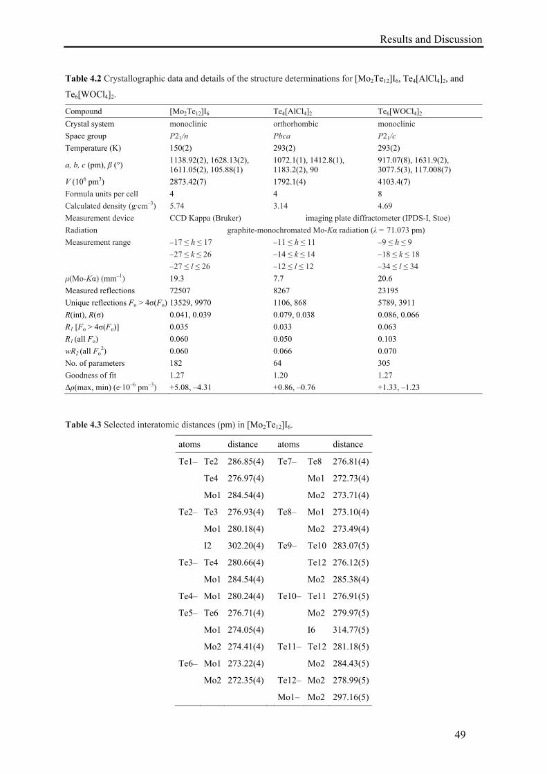
Results and Discussion
49
Table 4.2 Crystallographic data and details of the structure determinations for [Mo2Te12]I6, Te4[AlCl4]2, and
Te6[WOCl4]2.
Compound [Mo2Te12]I6 Te4[AlCl4]2 Te6[WOCl4]2
Crystal system monoclinic orthorhombic monoclinic
Space group P21/n Pbca P21/c
Temperature (K) 150(2) 293(2) 293(2)
a, b, c (pm), β (°) 1138.92(2), 1628.13(2), 1611.05(2), 105.88(1)
1072.1(1), 1412.8(1), 1183.2(2), 90
917.07(8), 1631.9(2), 3077.5(3), 117.008(7)
V (106 pm3) 2873.42(7) 1792.1(4) 4103.4(7)
Formula units per cell 4 4 8
Calculated density (g·cm–3) 5.74 3.14 4.69
Measurement device CCD Kappa (Bruker) imaging plate diffractometer (IPDS-I, Stoe)
Radiation graphite-monochromated Mo-Kα radiation (λ = 71.073 pm)
Measurement range –17 ≤ h ≤ 17 –11 ≤ h ≤ 11 –9 ≤ h ≤ 9
–27 ≤ k ≤ 26 –14 ≤ k ≤ 14 –18 ≤ k ≤ 18
–27 ≤ l ≤ 26 –12 ≤ l ≤ 12 –34 ≤ l ≤ 34
μ(Mo-Kα) (mm–1) 19.3 7.7 20.6
Measured reflections 72507 8267 23195
Unique reflections Fo > 4σ(Fo) 13529, 9970 1106, 868 5789, 3911
R(int), R(σ) 0.041, 0.039 0.079, 0.038 0.086, 0.066
R1 [Fo > 4σ(Fo)] 0.035 0.033 0.063
R1 (all Fo) 0.060 0.050 0.103
wR2 (all Fo2) 0.060 0.066 0.070
No. of parameters 182 64 305
Goodness of fit 1.27 1.20 1.27
Δρ(max, min) (e·10–6 pm–3) +5.08, –4.31 +0.86, –0.76 +1.33, –1.23
Table 4.3 Selected interatomic distances (pm) in [Mo2Te12]I6.
atoms distance atoms distance
Te1– Te2 286.85(4) Te7– Te8 276.81(4)
Te4 276.97(4) Mo1 272.73(4)
Mo1 284.54(4) Mo2 273.71(4)
Te2– Te3 276.93(4) Te8– Mo1 273.10(4)
Mo1 280.18(4) Mo2 273.49(4)
I2 302.20(4) Te9– Te10 283.07(5)
Te3– Te4 280.66(4) Te12 276.12(5)
Mo1 284.54(4) Mo2 285.38(4)
Te4– Mo1 280.24(4) Te10– Te11 276.91(5)
Te5– Te6 276.71(4) Mo2 279.97(5)
Mo1 274.05(4) I6 314.77(5)
Mo2 274.41(4) Te11– Te12 281.18(5)
Te6– Mo1 273.22(4) Mo2 284.43(5)
Mo2 272.35(4) Te12– Mo2 278.99(5)
Mo1– Mo2 297.16(5)
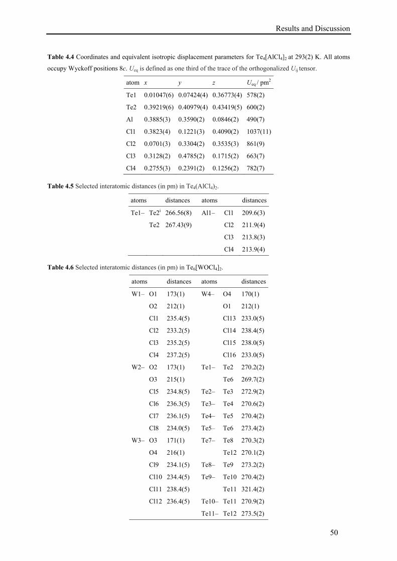
Results and Discussion
50
Table 4.4 Coordinates and equivalent isotropic displacement parameters for Te4[AlCl4]2 at 293(2) K. All atoms
occupy Wyckoff positions 8c. Ueq is defined as one third of the trace of the orthogonalized Uij tensor.
atom x y z Ueq / pm2
Te1 0.01047(6) 0.07424(4) 0.36773(4) 578(2)
Te2 0.39219(6) 0.40979(4) 0.43419(5) 600(2)
Al 0.3885(3) 0.3590(2) 0.0846(2) 490(7)
Cl1 0.3823(4) 0.1221(3) 0.4090(2) 1037(11)
Cl2 0.0701(3) 0.3304(2) 0.3535(3) 861(9)
Cl3 0.3128(2) 0.4785(2) 0.1715(2) 663(7)
Cl4 0.2755(3) 0.2391(2) 0.1256(2) 782(7)
Table 4.5 Selected interatomic distances (in pm) in Te4(AlCl4)2.
atoms distances atoms distances
Te1– Te2i 266.56(8) Al1– Cl1 209.6(3)
Te2 267.43(9) Cl2 211.9(4)
Cl3 213.8(3)
Cl4 213.9(4)
Table 4.6 Selected interatomic distances (in pm) in Te6[WOCl4]2.
atoms distances atoms distances
W1– O1 173(1) W4–
O4 170(1)
O2 212(1) O1 212(1)
Cl1 235.4(5) Cl13 233.0(5)
Cl2 233.2(5) Cl14 238.4(5)
Cl3 235.2(5) Cl15 238.0(5)
Cl4 237.2(5) Cl16 233.0(5)
W2– O2 173(1) Te1– Te2 270.2(2)
O3 215(1) Te6 269.7(2)
Cl5 234.8(5) Te2– Te3 272.9(2)
Cl6 236.3(5) Te3– Te4 270.6(2)
Cl7 236.1(5) Te4– Te5 270.4(2)
Cl8 234.0(5) Te5– Te6 273.4(2)
W3–
O3 171(1) Te7– Te8 270.3(2)
O4 216(1) Te12 270.1(2)
Cl9 234.1(5) Te8– Te9 273.2(2)
Cl10 234.4(5) Te9– Te10 270.4(2)
Cl11 238.4(5) Te11 321.4(2)
Cl12 236.4(5) Te10– Te11 270.9(2)
Te11– Te12 273.5(2)
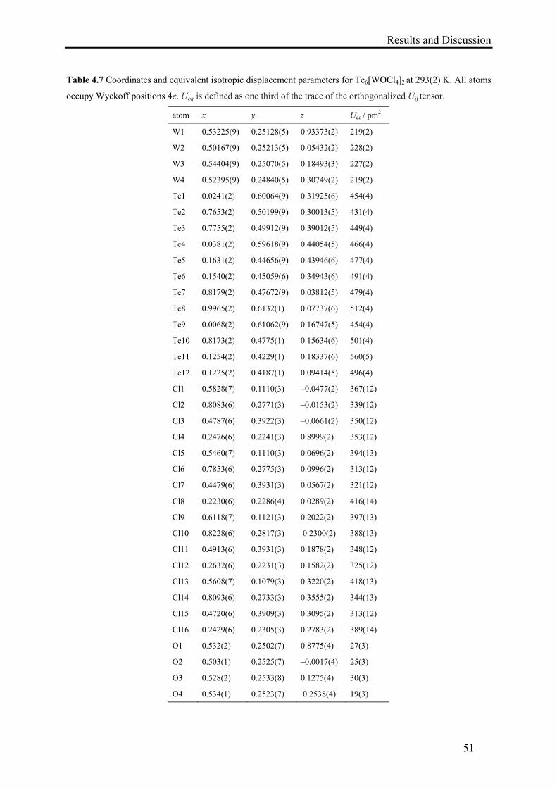
Results and Discussion
51
Table 4.7 Coordinates and equivalent isotropic displacement parameters for Te6[WOCl4]2 at 293(2) K. All atoms
occupy Wyckoff positions 4e. Ueq is defined as one third of the trace of the orthogonalized Uij tensor.
atom x y z Ueq / pm2
W1 0.53225(9) 0.25128(5) 0.93373(2) 219(2)
W2 0.50167(9) 0.25213(5) 0.05432(2) 228(2)
W3 0.54404(9) 0.25070(5) 0.18493(3) 227(2)
W4 0.52395(9) 0.24840(5) 0.30749(2) 219(2)
Te1 0.0241(2) 0.60064(9) 0.31925(6) 454(4)
Te2 0.7653(2) 0.50199(9) 0.30013(5) 431(4)
Te3 0.7755(2) 0.49912(9) 0.39012(5) 449(4)
Te4 0.0381(2) 0.59618(9) 0.44054(5) 466(4)
Te5 0.1631(2) 0.44656(9) 0.43946(6) 477(4)
Te6 0.1540(2) 0.45059(6) 0.34943(6) 491(4)
Te7 0.8179(2) 0.47672(9) 0.03812(5) 479(4)
Te8 0.9965(2) 0.6132(1) 0.07737(6) 512(4)
Te9 0.0068(2) 0.61062(9) 0.16747(5) 454(4)
Te10 0.8173(2) 0.4775(1) 0.15634(6) 501(4)
Te11 0.1254(2) 0.4229(1) 0.18337(6) 560(5)
Te12 0.1225(2) 0.4187(1) 0.09414(5) 496(4)
Cl1 0.5828(7) 0.1110(3) –0.0477(2) 367(12)
Cl2 0.8083(6) 0.2771(3) –0.0153(2) 339(12)
Cl3 0.4787(6) 0.3922(3) –0.0661(2) 350(12)
Cl4 0.2476(6) 0.2241(3) 0.8999(2) 353(12)
Cl5 0.5460(7) 0.1110(3) 0.0696(2) 394(13)
Cl6 0.7853(6) 0.2775(3) 0.0996(2) 313(12)
Cl7 0.4479(6) 0.3931(3) 0.0567(2) 321(12)
Cl8 0.2230(6) 0.2286(4) 0.0289(2) 416(14)
Cl9 0.6118(7) 0.1121(3) 0.2022(2) 397(13)
Cl10 0.8228(6) 0.2817(3) 0.2300(2) 388(13)
Cl11 0.4913(6) 0.3931(3) 0.1878(2) 348(12)
Cl12 0.2632(6) 0.2231(3) 0.1582(2) 325(12)
Cl13 0.5608(7) 0.1079(3) 0.3220(2) 418(13)
Cl14 0.8093(6) 0.2733(3) 0.3555(2) 344(13)
Cl15 0.4720(6) 0.3909(3) 0.3095(2) 313(12)
Cl16 0.2429(6) 0.2305(3) 0.2783(2) 389(14)
O1 0.532(2) 0.2502(7) 0.8775(4) 27(3)
O2 0.503(1) 0.2525(7) –0.0017(4) 25(3)
O3 0.528(2) 0.2533(8) 0.1275(4) 30(3)
O4 0.534(1) 0.2523(7) 0.2538(4) 19(3)
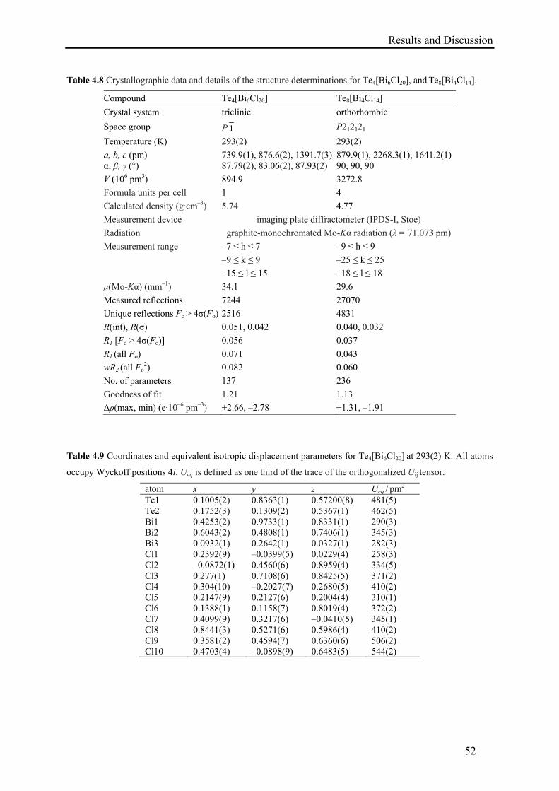
Results and Discussion
52
Table 4.8 Crystallographic data and details of the structure determinations for Te4[Bi6Cl20], and Te8[Bi4Cl14].
Compound Te4[Bi6Cl20] Te8[Bi4Cl14]
Crystal system triclinic orthorhombic
Space group P 1 P212121
Temperature (K) 293(2) 293(2)
a, b, c (pm) α, β, γ (°)
739.9(1), 876.6(2), 1391.7(3) 87.79(2), 83.06(2), 87.93(2)
879.9(1), 2268.3(1), 1641.2(1) 90, 90, 90
V (106 pm3) 894.9 3272.8
Formula units per cell 1 4
Calculated density (g·cm–3) 5.74 4.77
Measurement device imaging plate diffractometer (IPDS-I, Stoe)
Radiation graphite-monochromated Mo-Kα radiation (λ = 71.073 pm)
Measurement range –7 ≤ h ≤ 7 –9 ≤ h ≤ 9
–9 ≤ k ≤ 9 –25 ≤ k ≤ 25
–15 ≤ l ≤ 15 –18 ≤ l ≤ 18
μ(Mo-Kα) (mm–1) 34.1 29.6
Measured reflections 7244 27070
Unique reflections Fo > 4σ(Fo) 2516 4831
R(int), R(σ) 0.051, 0.042 0.040, 0.032
R1 [Fo > 4σ(Fo)] 0.056 0.037
R1 (all Fo) 0.071 0.043
wR2 (all Fo2) 0.082 0.060
No. of parameters 137 236
Goodness of fit 1.21 1.13
Δρ(max, min) (e·10–6 pm–3) +2.66, –2.78 +1.31, –1.91
Table 4.9 Coordinates and equivalent isotropic displacement parameters for Te4[Bi6Cl20] at 293(2) K. All atoms
occupy Wyckoff positions 4i. Ueq is defined as one third of the trace of the orthogonalized Uij tensor.
atom x y z Ueq / pm2 Te1 0.1005(2) 0.8363(1) 0.57200(8) 481(5) Te2 0.1752(3) 0.1309(2) 0.5367(1) 462(5) Bi1 0.4253(2) 0.9733(1) 0.8331(1) 290(3) Bi2 0.6043(2) 0.4808(1) 0.7406(1) 345(3) Bi3 0.0932(1) 0.2642(1) 0.0327(1) 282(3) Cl1 0.2392(9) –0.0399(5) 0.0229(4) 258(3) Cl2 –0.0872(1) 0.4560(6) 0.8959(4) 334(5) Cl3 0.277(1) 0.7108(6) 0.8425(5) 371(2) Cl4 0.304(10) –0.2027(7) 0.2680(5) 410(2) Cl5 0.2147(9) 0.2127(6) 0.2004(4) 310(1) Cl6 0.1388(1) 0.1158(7) 0.8019(4) 372(2) Cl7 0.4099(9) 0.3217(6) –0.0410(5) 345(1) Cl8 0.8441(3) 0.5271(6) 0.5986(4) 410(2) Cl9 0.3581(2) 0.4594(7) 0.6360(6) 506(2) Cl10 0.4703(4) –0.0898(9) 0.6483(5) 544(2)
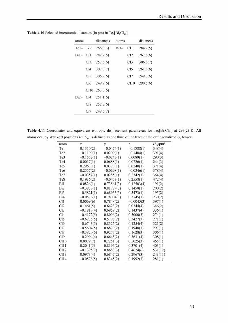
Results and Discussion
53
Table 4.10 Selected interatomic distances (in pm) in Te4[Bi6Cl20].
atoms distances atoms distances
Te1– Te2 266.8(3) Bi3–
Cl1 284.2(5)
Bi1–
Cl1 282.7(5) Cl2 267.8(6)
Cl3 257.6(6) Cl3 306.8(7)
Cl4 307.0(7) Cl5 261.8(6)
Cl5 306.9(6) Cl7 249.7(6)
Cl6 249.7(6) Cl10 290.5(6)
Cl10 263.0(6)
Bi2–
Cl4 251.1(6)
Cl8 252.3(6)
Cl9 248.5(7)
Table 4.11 Coordinates and equivalent isotropic displacement parameters for Te8[Bi4Cl14] at 293(2) K. All
atoms occupy Wyckoff positions 4a. Ueq is defined as one third of the trace of the orthogonalized Uij tensor.
atom x y z Ueq/pm² Te1 0.1310(2) –0.0474(1) –0.1888(1) 348(4) Te2 –0.1199(1) 0.0209(1) –0.1404(1) 391(4) Te3 –0.1552(1) –0.0247(1) 0.0089(1) 290(3) Te4 0.0017(1) 0.0688(1) 0.0726(1) 244(3) Te5 0.2963(1) 0.0378(1) 0.0240(1) 371(4) Te6 0.2557(2) –0.0698(1) –0.0346(1) 378(4) Te7 –0.0357(1) 0.0285(1) 0.2342(1) 364(4) Te8 0.1936(2) –0.0453(1) 0.2558(1) 472(4) Bi1 0.0826(1) 0.73561(3) 0.12503(4) 191(2) Bi2 –0.3877(1) 0.81779(3) 0.1458(1) 200(2) Bi3 –0.5821(1) 0.68933(3) 0.3473(1) 195(2) Bi4 –0.0576(1) 0.78004(3) 0.3745(1) 230(2) Cl1 0.0069(6) 0.7848(2) –0.0045(3) 397(1) Cl2 0.1461(5) 0.6423(2) 0.0344(4) 346(2) Cl3 –0.1818(4) 0.6959(2) 0.1437(4) 336(1) Cl4 –0.4172(5) 0.8096(2) 0.3000(3) 274(1) Cl5 –0.6275(5) 0.5798(2) 0.3427(3) 271(1) Cl6 –0.6743(5) 0.8325(2) 0.1254(4) 321(2) Cl7 –0.5604(5) 0.6879(2) 0.1940(3) 297(1) Cl8 –0.3820(6) 0.9273(2) 0.1628(3) 306(1) Cl9 –0.2994(4) 0.6645(2) 0.3631(4) 308(1) Cl10 0.0079(7) 0.7251(3) 0.5025(3) 465(1) Cl11 0.2041(5) 0.8196(2) 0.3701(4) 403(1) Cl12 –0.1395(7) 0.8683(3) 0.4624(6) 531(12) Cl13 0.0973(4) 0.6847(2) 0.2967(3) 243(11) Cl14 –0.0578(5) 0.8345(2) 0.1992(3) 281(1)
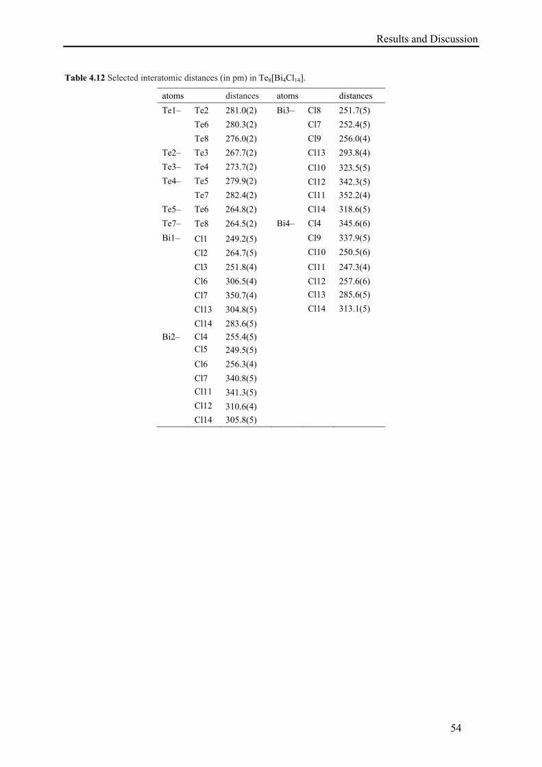
Results and Discussion
54
Table 4.12 Selected interatomic distances (in pm) in Te8[Bi4Cl14].
atoms distances atoms distances
Te1– Te2 281.0(2) Bi3– Cl8 251.7(5)
Te6 280.3(2) Cl7 252.4(5)
Te8 276.0(2) Cl9 256.0(4)
Te2– Te3 267.7(2) Cl13 293.8(4)
Te3– Te4 273.7(2) Cl10 323.5(5)
Te4– Te5 279.9(2) Cl12 342.3(5)
Te7 282.4(2) Cl11 352.2(4)
Te5– Te6 264.8(2) Cl14 318.6(5)
Te7– Te8 264.5(2) Bi4– Cl4 345.6(6)
Bi1– Cl1 249.2(5) Cl9 337.9(5)
Cl2 264.7(5) Cl10 250.5(6)
Cl3 251.8(4) Cl11 247.3(4)
Cl6 306.5(4) Cl12 257.6(6)
Cl7 350.7(4) Cl13 285.6(5)
Cl13 304.8(5) Cl14 313.1(5)
Cl14 283.6(5)
Bi2– Cl4 255.4(5)
Cl5 249.5(5)
Cl6 256.3(4)
Cl7 340.8(5)
Cl11 341.3(5)
Cl12 310.6(4)
Cl14 305.8(5)
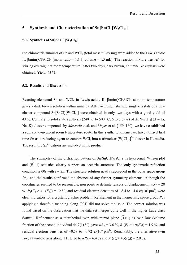
Results and Discussion
55
5. Synthesis and Characterization of Sn[SnCl][W3Cl13]
5.1. Synthesis of Sn[SnCl][W3Cl13]
Stoichiometric amounts of Sn and WCl6 (total mass = 285 mg) were added to the Lewis acidic
IL [bmim]Cl/AlCl3 (molar ratio = 1:1.3, volume = 1.5 mL). The reaction mixture was left for
stirring overnight at room temperature. After two days, dark brown, column-like crystals were
obtained. Yield: 43 %.
5.2. Results and Discussion
Reacting elemental Sn and WCl6 in Lewis acidic IL [bmim]Cl/AlCl3 at room temperature
gives a dark brown solution within minutes. After overnight stirring, single-crystals of a new
cluster compound Sn[SnCl][W3Cl13] were obtained in only two days with a good yield of
43 %. Contrary to solid state synthesis (240 °C to 500 °C, 6 to 7 days) of A3[W3Cl13] (A = Li,
Na, K) cluster compounds by Messerle et al. and Meyer et al. [159, 160], we have established
a soft and convenient room temperature route. In this synthetic scheme, we have utilized first
time Sn as a reducing agent to convert WCl6 into a trinuclear [W3Cl13]3– cluster in IL media.
The resulting Sn2+ cations are included in the product.
The symmetry of the diffraction pattern of Sn[SnCl][W3Cl13] is hexagonal. Wilson plot
and (E2–1) statistics clearly support an acentric structure. The only systematic reflection
condition is 00l with l = 2n. The structure solution neatly succeeded in the polar space group
P63, and the results confirmed the absence of any further symmetry elements. Although the
coordinates seemed to be reasonable, non positive definite tensors of displacement, wR2 = 28
%, R1(Fo > 4�(Fo)) = 12 %, and residual electron densities of +8.4 to –4.8 e/(106 pm3) were
clear indicators for a crystallographic problem. Refinement in the monoclinic space group P21
applying a threefold twinning along [001] did not solve the issue. The correct solution was
found based on the observation that the data set merges quite well in the higher Laue class
6/mmm. Refinement as a merohedral twin with mirror plane ( 101 ) as twin law (volume
fraction of the second individual 44.7(1) %) gave wR2 = 3.6 %, R1(Fo > 4(Fo)) = 1.9 %, and
residual electron densities of +0.58 to –0.72 e/(106 pm3). Remarkably, the alternative twin
law, a two-fold axis along [110], led to wR2 = 6.4 % and R1(Fo > 4(Fo)) = 2.9 %.
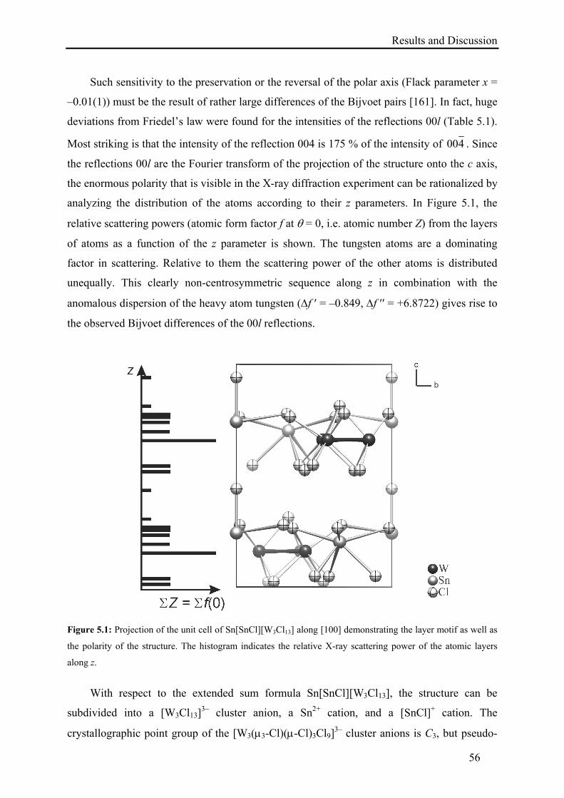
Results and Discussion
56
Such sensitivity to the preservation or the reversal of the polar axis (Flack parameter x =
–0.01(1)) must be the result of rather large differences of the Bijvoet pairs [161]. In fact, huge
deviations from Friedel’s law were found for the intensities of the reflections 00l (Table 5.1).
Most striking is that the intensity of the reflection 004 is 175 % of the intensity of 400 . Since
the reflections 00l are the Fourier transform of the projection of the structure onto the c axis,
the enormous polarity that is visible in the X-ray diffraction experiment can be rationalized by
analyzing the distribution of the atoms according to their z parameters. In Figure 5.1, the
relative scattering powers (atomic form factor f at = 0, i.e. atomic number Z) from the layers
of atoms as a function of the z parameter is shown. The tungsten atoms are a dominating
factor in scattering. Relative to them the scattering power of the other atoms is distributed
unequally. This clearly non-centrosymmetric sequence along z in combination with the
anomalous dispersion of the heavy atom tungsten (f ′ = –0.849, f ′′ = +6.8722) gives rise to
the observed Bijvoet differences of the 00l reflections.
Figure 5.1: Projection of the unit cell of Sn[SnCl][W3Cl13] along [100] demonstrating the layer motif as well as
the polarity of the structure. The histogram indicates the relative X-ray scattering power of the atomic layers
along z.
With respect to the extended sum formula Sn[SnCl][W3Cl13], the structure can be
subdivided into a [W3Cl13]3– cluster anion, a Sn2+ cation, and a [SnCl]+ cation. The
crystallographic point group of the [W3(3-Cl)(-Cl)3Cl9]3– cluster anions is C3, but pseudo-
Results and Discussion
57
symmetry C3v is observed within double standard deviation. The bonding W–W distance of
272.18(6) pm is in excellent agreement with those in Na3[W3Cl13] (273.7(1) pm) [160]. W
atoms are additionally connected by one μ3-Cl– and three μ-Cl– ligands. Each W atom is
further coordinated by three terminal Cl– ions. Irrespective of the connectivity, the W–Cl
distances are very similar (238.4(3) to 247.6(3) pm). Consequently, the W atom is in a slightly
distorted octahedral environment (Figure 5.2). Comparable isolated groups [Bi3Br13]4–
(without metal-metal bonds) [56e] as well as interconnected clusters [Nb3Cl13]n– [162] have
been described previously.
Figure 5.2: One layer in the crystal structure of Sn[SnCl][W3Cl13]. The second layer is obtained by 63 screw
rotation along the c axis.
The trinuclear [W3Cl13]3– cluster anions are encircled by Sn2+ cations, which link them
into a two-dimensional network parallel to (001). The cation Sn1 is in distorted trigonal-
antiprismatic coordination by six Cl– anions with three short (269.0(3) pm) and three long
distances (307.7(4) pm). The lone-pair of the Sn2+ cation might be directed towards the center
of the wide triangular face that is formed by Cl5 atoms (Cl···Cl: 517 pm).
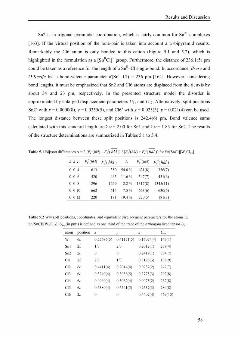
Results and Discussion
58
Sn2 is in trigonal pyramidal coordination, which is fairly common for Sn2+ complexes
[163]. If the virtual position of the lone-pair is taken into account a -bipyramid results.
Remarkably the Cl6 anion is only bonded to this cation (Figure 5.1 and 5.2), which is
highlighted in the formulation as a [SnIICl]+ group. Furthermore, the distance of 236.1(5) pm
could be taken as a reference for the length of a SnII–Cl single-bond. In accordance, Brese and
O’Keeffe list a bond-valence parameter R(SnII–Cl) = 236 pm [164]. However, considering
bond lengths, it must be emphasized that Sn2 and Cl6 atoms are displaced from the 63 axis by
about 34 and 23 pm, respectively. In the presented structure model the disorder is
approximated by enlarged displacement parameters U11 and U12. Alternatively, split positions
Sn2’ with x = 0.0000(8), y = 0.0355(5), and Cl6’ with x = 0.025(3), y = 0.021(4) can be used.
The longest distance between these split positions is 242.4(6) pm. Bond valence sums
calculated with this standard length are = 2.00 for Sn1 and = 1.83 for Sn2. The results
of the structure determinations are summarized in Tables 5.1 to 5.4.
Table 5.1 Bijvoet differences = 2 [Fc2(hkl) – Fc
2( hkl )] / [Fc2(hkl) + Fc
2( hkl )] for Sn[SnCl][W3Cl13].
h k l Fc2(hkl) Fc
2( hkl ) Fo2(hkl) Fo
2( hkl )
0 0 4 613 350 54.6 % 621(8) 336(7)
0 0 6 520 463 11.6 % 547(7) 451(6)
0 0 8 1296 1269 2.2 % 1317(8) 1345(11)
0 0 10 662 614 7.5 % 663(6) 630(6)
0 0 12 220 181 19.4 % 220(5) 181(3)
Table 5.2 Wyckoff positions, coordinates, and equivalent displacement parameters for the atoms in
Sn[SnCl][W3Cl13]. Ueq (in pm2) is defined as one third of the trace of the orthogonalized tensor Uij.
atom position x y z Ueq
W 6c 0.55686(5) 0.41171(5) 0.16074(4) 143(1)
Sn1 2b 1/3 2/3 0.2012(1) 279(4)
Sn2 2a 0 0 0.2419(1) 784(7)
Cl1 2b 2/3 1/3 0.3128(3) 139(9)
Cl2 6c 0.4411(4) 0.2014(4) 0.0237(2) 242(7)
Cl3 6c 0.3240(4) 0.3036(5) 0.2775(3) 292(8)
Cl4 6c 0.4040(4) 0.5062(4) 0.0473(2) 262(8)
Cl5 6c 0.6380(4) 0.6541(5) 0.2637(3) 280(8)
Cl6 2a 0 0 0.4402(4) 469(15)
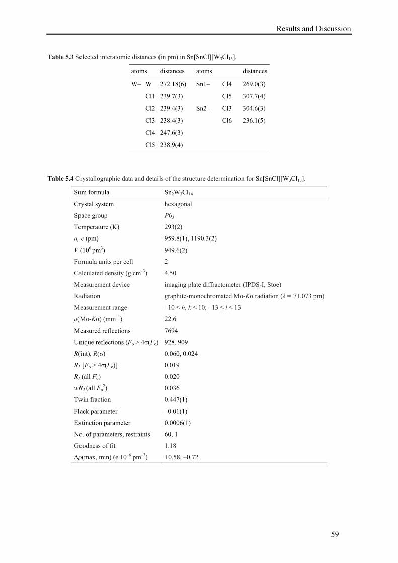
Results and Discussion
59
Table 5.3 Selected interatomic distances (in pm) in Sn[SnCl][W3Cl13].
atoms distances atoms distances
W– W 272.18(6) Sn1– Cl4 269.0(3)
Cl1 239.7(3) Cl5 307.7(4)
Cl2 239.4(3) Sn2– Cl3 304.6(3)
Cl3 238.4(3) Cl6 236.1(5)
Cl4 247.6(3)
Cl5 238.9(4)
Table 5.4 Crystallographic data and details of the structure determination for Sn[SnCl][W3Cl13].
Sum formula Sn2W3Cl14
Crystal system hexagonal
Space group P63
Temperature (K) 293(2)
a, c (pm) 959.8(1), 1190.3(2)
V (106 pm3) 949.6(2)
Formula units per cell 2
Calculated density (g·cm–3) 4.50
Measurement device imaging plate diffractometer (IPDS-I, Stoe)
Radiation graphite-monochromated Mo-Kα radiation (λ = 71.073 pm)
Measurement range –10 ≤ h, k ≤ 10; –13 ≤ l ≤ 13
μ(Mo-Kα) (mm–1) 22.6
Measured reflections 7694
Unique reflections (Fo > 4σ(Fo) 928, 909
R(int), R(σ) 0.060, 0.024
R1 [Fo > 4σ(Fo)] 0.019
R1 (all Fo) 0.020
wR2 (all Fo2) 0.036
Twin fraction 0.447(1)
Flack parameter –0.01(1)
Extinction parameter 0.0006(1)
No. of parameters, restraints 60, 1
Goodness of fit 1.18
Δρ(max, min) (e·10–6 pm–3) +0.58, –0.72
Results and Discussion
60
6. Synthesis and Characterization of Molybdenum Cluster Compounds
6.1. Synthesis of Bi[Mo5Cl13]Cl
Stoichiometric amounts of Bi, BiCl3 and MoCl5 (total mass = 275 mg) were added to the
Lewis acidic IL [bmim]Cl/AlCl3 (molar ratio = 1:1.3, volume = 1.5 mL). The dark blue
reaction mixture was left for stirring overnight at room temperature then filtered to separate
unreacted material. Addition of anhydrous NaCl helped to get black, cube-shaped crystals in
only three days. Yield: 47 %.
6.2. Synthesis of BiCl[Mo6Cl14]
The same procedure was used as described for Bi[Mo5Cl13]Cl, starting from Bi and MoCl5
(total mass = 290 mg), i.e. BiCl3 was omitted in the synthesis. Addition of a small amount of
anhydrous NaCl into the red filtrate led to the precipitation of light red crystals in only two
days. Yield: 56 %.
6.3. Results and Discussion
Reacting elemental Bi, BiCl3, and MoCl5 in Lewis acidic IL [bmim]Cl/AlCl3 at room
temperature gave a dark blue solution within minutes. After overnight stirring, black, cube-
shaped single-crystals of Bi[Mo5Cl13]Cl were obtained in only three days. Contrary to the
multi-step synthesis of A2[Mo5X13] (A = n-Bu4N
+, Ph4As+; X = Cl, Br) cluster compounds
from K3MoCl6 or MoCl2 in melts of Bi, BiCl3, AlCl3, and KCl at 306 °C by Schäfer et al.
[165, 166] and Gray et al. [167], we have established a single-step, soft and convenient room
temperature route. In this synthetic scheme, we have utilized elemental Bi as a reducing agent
to convert MoCl5 into a pentanuclear [Mo5Cl13]2– cluster in IL media. The resulting
bismuth(III) cations are included in the product.
The crystal structure of Bi[Mo5Cl13]Cl has been solved in the cubic centrosymmetric
space group Pn 3 depending upon the observed reflections symmetry. All attempts to refine
ordered structure models of lower symmetry, including multiple twinning, failed. The
structure of Bi[Mo5Cl13]Cl (Figure 6.1) is a defect variant of the Pb[Mo6Cl14] type [168]. One
of the molybdenum atoms of the Mo6 cluster core is missing, resulting in a [Mo5 Cl13]2–
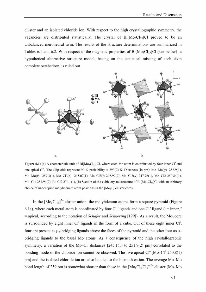
Results and Discussion
61
cluster and an isolated chloride ion. With respect to the high crystallographic symmetry, the
vacancies are distributed statistically. The crystal of Bi[Mo5Cl13]Cl proved to be an
unbalanced merohedral twin. The results of the structure determinations are summarized in
Tables 6.1 and 6.2. With respect to the magnetic properties of Bi[Mo5Cl13]Cl (see below) a
hypothetical alternative structure model, basing on the statistical missing of each sixth
complete octahedron, is ruled out.
Figure 6.1: (a) A characteristic unit of Bi[Mo5Cl13]Cl, where each Mo atom is coordinated by four inner Cli and
one apical Cla. The ellipsoids represent 90 % probability at 293(2) K. Distances (in pm): Mo–Mo(q) 258.9(1),
Mo–Mo(r) 259.3(1), Mo–Cl3(s) 245.07(1), Mo–Cl3(t) 246.99(2), Mo–Cl3(u) 247.76(1), Mo–Cl2 250.84(1),
Mo–Cl1 251.94(2), Bi–Cl2 274.1(1), (b) Section of the cubic crystal structure of Bi[Mo5Cl13]Cl with an arbitrary
choice of unoccupied molybdenum atom positions in the [Mo5 ] cluster cores.
In the [Mo5Cl13]2– cluster anion, the molybdenum atoms form a square pyramid (Figure
6.1a), where each metal atom is coordinated by four Cli ligands and one Cla ligand (i = inner, a
= apical, according to the notation of Schäfer and Schnering [129]). As a result, the Mo5 core
is surrounded by eight inner Cli ligands in the form of a cube. Out of these eight inner Cli,
four are present as 3-bridging ligands above the faces of the pyramid and the other four as -
bridging ligands to the basal Mo atoms. As a consequence of the high crystallographic
symmetry, a variation of the Mo–Cli distances [245.1(1) to 251.9(2) pm] correlated to the
bonding mode of the chloride ion cannot be observed. The five apical Cla [Mo–Cla 250.8(1)
pm] and the isolated chloride ion are also bonded to the bismuth cation. The average Mo–Mo
bond length of 259 pm is somewhat shorter than those in the [Mo6Cl8iCl6
a]2– cluster (Mo–Mo
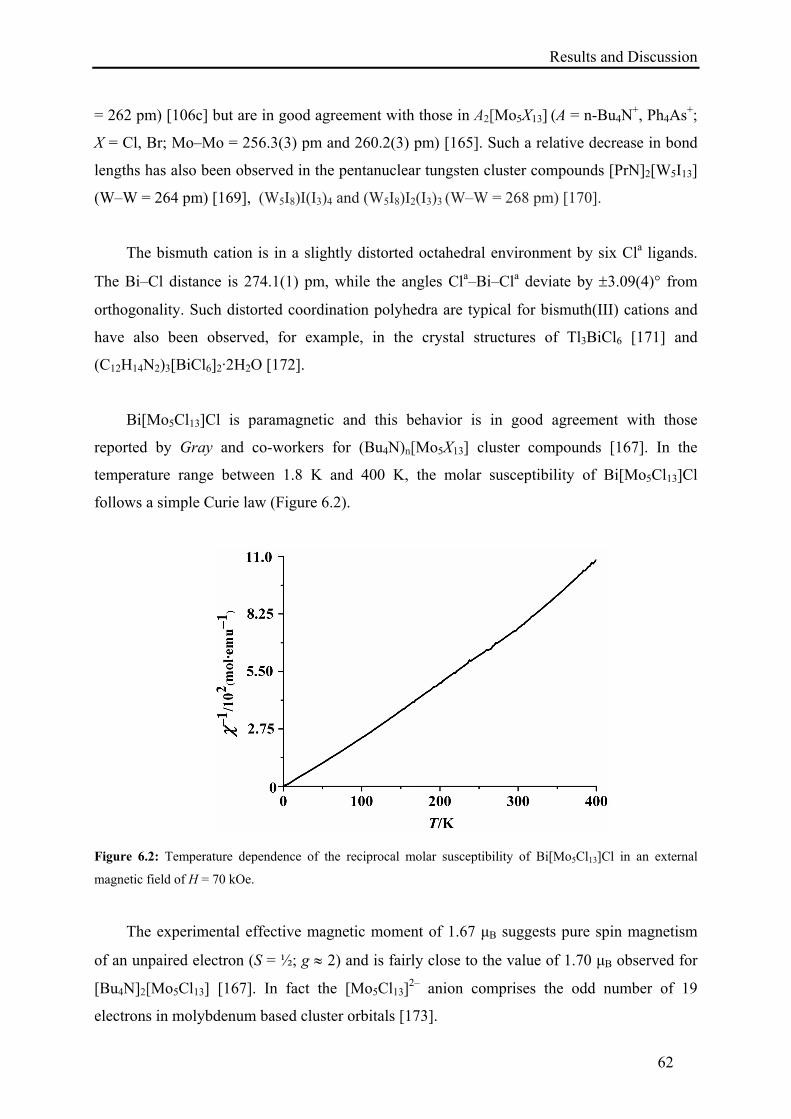
Results and Discussion
62
= 262 pm) [106c] but are in good agreement with those in A2[Mo5X13] (A = n-Bu4N
+, Ph4As+;
X = Cl, Br; Mo–Mo = 256.3(3) pm and 260.2(3) pm) [165]. Such a relative decrease in bond
lengths has also been observed in the pentanuclear tungsten cluster compounds [PrN]2[W5I13]
(W–W = 264 pm) [169], (W5I8)I(I3)4 and (W5I8)I2(I3)3 (W–W = 268 pm) [170].
The bismuth cation is in a slightly distorted octahedral environment by six Cla ligands.
The Bi–Cl distance is 274.1(1) pm, while the angles Cla–Bi–Cla deviate by 3.09(4)° from
orthogonality. Such distorted coordination polyhedra are typical for bismuth(III) cations and
have also been observed, for example, in the crystal structures of Tl3BiCl6 [171] and
(C12H14N2)3[BiCl6]2·2H2O [172].
Bi[Mo5Cl13]Cl is paramagnetic and this behavior is in good agreement with those
reported by Gray and co-workers for (Bu4N)n[Mo5X13] cluster compounds [167]. In the
temperature range between 1.8 K and 400 K, the molar susceptibility of Bi[Mo5Cl13]Cl
follows a simple Curie law (Figure 6.2).
Figure 6.2: Temperature dependence of the reciprocal molar susceptibility of Bi[Mo5Cl13]Cl in an external
magnetic field of H = 70 kOe.
The experimental effective magnetic moment of 1.67 μB suggests pure spin magnetism
of an unpaired electron (S = ½; g 2) and is fairly close to the value of 1.70 μB observed for
[Bu4N]2[Mo5Cl13] [167]. In fact the [Mo5Cl13]2– anion comprises the odd number of 19
electrons in molybdenum based cluster orbitals [173].
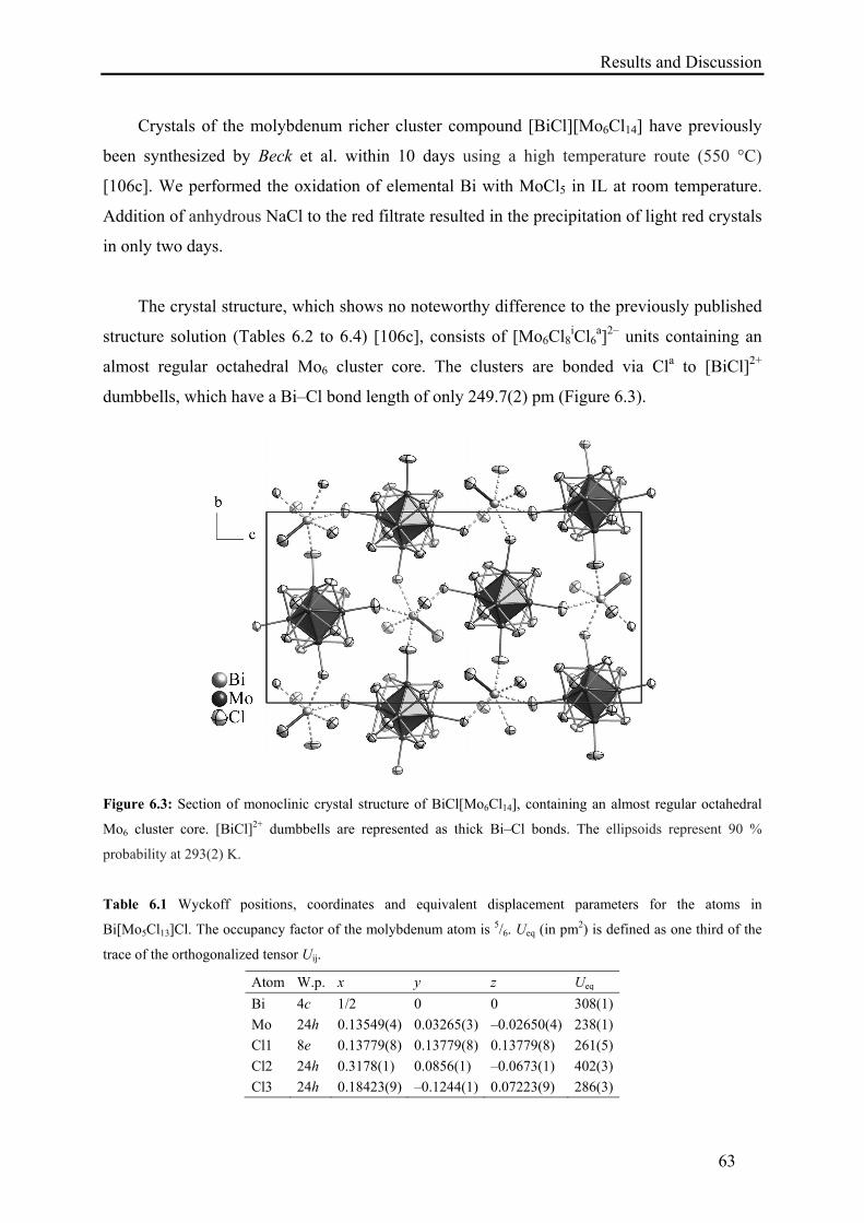
Results and Discussion
63
Crystals of the molybdenum richer cluster compound [BiCl][Mo6Cl14] have previously
been synthesized by Beck et al. within 10 days using a high temperature route (550 °C)
[106c]. We performed the oxidation of elemental Bi with MoCl5 in IL at room temperature.
Addition of anhydrous NaCl to the red filtrate resulted in the precipitation of light red crystals
in only two days.
The crystal structure, which shows no noteworthy difference to the previously published
structure solution (Tables 6.2 to 6.4) [106c], consists of [Mo6Cl8iCl6
a]2– units containing an
almost regular octahedral Mo6 cluster core. The clusters are bonded via Cla to [BiCl]2+
dumbbells, which have a Bi–Cl bond length of only 249.7(2) pm (Figure 6.3).
Figure 6.3: Section of monoclinic crystal structure of BiCl[Mo6Cl14], containing an almost regular octahedral
Mo6 cluster core. [BiCl]2+ dumbbells are represented as thick Bi–Cl bonds. The ellipsoids represent 90 %
probability at 293(2) K.
Table 6.1 Wyckoff positions, coordinates and equivalent displacement parameters for the atoms in
Bi[Mo5Cl13]Cl. The occupancy factor of the molybdenum atom is 5/6. Ueq (in pm2) is defined as one third of the
trace of the orthogonalized tensor Uij.
Atom W.p. x y z Ueq
Bi 4c 1/2 0 0 308(1)
Mo 24h 0.13549(4) 0.03265(3) –0.02650(4) 238(1)
Cl1 8e 0.13779(8) 0.13779(8) 0.13779(8) 261(5)
Cl2 24h 0.3178(1) 0.0856(1) –0.0673(1) 402(3)
Cl3 24h 0.18423(9) –0.1244(1) 0.07223(9) 286(3)
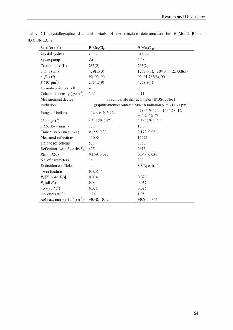
Results and Discussion
64
Table 6.2 Crystallographic data and details of the structure determination for Bi[Mo5Cl13]Cl and
[BiCl][Mo6Cl14].
Sum formula BiMo5Cl14 BiMo6Cl15
Crystal system cubic monoclinic
Space group Pn 3 C2/c
Temperature (K) 293(2) 293(2)
a, b, c (pm) 1291.6(3) 1267.6(1), 1304.3(1), 2573.8(3)
α, β, γ (°) 90, 90, 90 90, 91.782(8), 90
V (106 pm3) 2154.7(9) 4253.3(7)
Formula units per cell 4 8
Calculated density (g·cm–3) 3.65 4.11
Measurement device imaging plate diffractometer (IPDS-I, Stoe)
Radiation graphite-monochromated Mo-Kα radiation (λ = 71.073 pm)
Range of indices –14 ≤ h, k, l ≤ 14 –13 ≤ h ≤ 14, –14 ≤ k ≤ 14, –28 ≤ l ≤ 28
2θ range (°) 4.5 ≤ 2θ ≤ 47.4 4.5 ≤ 2θ ≤ 47.0
μ(Mo-Kα) (mm–1) 12.7 13.5
Transmission(max, min) 0.455, 0.326 0.172, 0.051
Measured reflections 11600 11627
Unique reflections 537 3083
Reflections with Fo > 4σ(Fo) 475 2616
R(int), R(σ) 0.109, 0.025 0.049, 0.036
No. of parameters 34 200
Extinction coefficient — 8.8(3) 10–5
Twin fraction 0.028(1) —
R1 [Fo > 4σ(Fo)] 0.034 0.026
R1 (all Fo) 0.044 0.037
wR2 (all Fo2) 0.021 0.026
Goodness of fit 1.26 1.05
Δρ(max, min) (e·10–6 pm–3) +0.40, –0.52 +0.64, –0.64
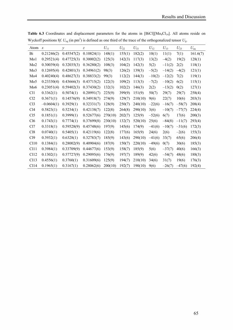
Results and Discussion
65
Table 6.3 Coordinates and displacement parameters for the atoms in [BiCl][Mo6Cl14]. All atoms reside on
Wyckoff positions 8f. Ueq (in pm2) is defined as one third of the trace of the orthogonalized tensor Uij.
Atom x y z U11 U22 U33 U12 U13 U23 Ueq
Bi 0.21246(2) 0.45547(2) 0.10824(1) 148(1) 155(1) 182(2) 10(1) 11(1) 7(1) 161.6(7)
Mo1 0.29521(4) 0.47725(3) 0.30002(2) 125(3) 142(3) 117(3) 13(2) –4(2) 19(2) 128(1)
Mo2 0.30039(4) 0.32035(3) 0.36280(2) 108(3) 104(2) 142(3) 5(2) –11(2) 2(2) 118(1)
Mo3 0.12695(4) 0.42801(3) 0.34961(2) 98(3) 126(2) 139(3) –5(2) –14(2) –4(2) 121(1)
Mo4 0.40240(4) 0.48627(3) 0.38833(2) 99(3) 112(2) 144(3) –10(2) –12(2) 7(2) 119(1)
Mo5 0.23330(4) 0.43666(3) 0.43715(2) 122(3) 109(2) 113(3) –7(2) –10(2) 6(2) 115(1)
Mo6 0.23051(4) 0.59402(3) 0.37430(2) 132(3) 102(2) 146(3) 2(2) –13(2) 0(2) 127(1)
Cl1 0.3362(1) 0.5074(1) 0.20991(7) 225(9) 399(9) 151(9) 50(7) 29(7) 29(7) 258(4)
Cl2 0.3671(1) 0.14576(9) 0.34918(7) 274(9) 129(7) 210(10) 9(6) 22(7) 10(6) 203(3)
Cl3 –0.0604(1) 0.3929(1) 0.32331(7) 128(9) 250(7) 240(10) –22(6) –16(7) –58(7) 208(4)
Cl4 0.5823(1) 0.5234(1) 0.42138(7) 122(8) 264(8) 290(10) 3(6) –10(7) –77(7) 224(4)
Cl5 0.1851(1) 0.3999(1) 0.52677(6) 270(10) 202(7) 125(9) –52(6) 6(7) 17(6) 200(3)
Cl6 0.1743(1) 0.7774(1) 0.37699(8) 230(10) 132(7) 520(10) 25(6) –84(8) –11(7) 293(4)
Cl7 0.3318(1) 0.59528(9) 0.45748(6) 197(9) 145(6) 174(9) –41(6) –10(7) –31(6) 172(3)
Cl8 0.0740(1) 0.5405(1) 0.42119(6) 122(8) 177(6) 165(9) 24(6) 2(6) –2(6) 155(3)
Cl9 0.3932(1) 0.6328(1) 0.32783(7) 185(9) 143(6) 290(10) –41(6) 33(7) 65(6) 206(4)
Cl10 0.1384(1) 0.28002(9) 0.40904(6) 187(9) 150(7) 220(10) –49(6) 0(7) 30(6) 185(3)
Cl11 0.3984(1) 0.33709(9) 0.44677(6) 153(9) 158(7) 185(9) 5(6) –37(7) 40(6) 166(3)
Cl12 0.1302(1) 0.57727(9) 0.29095(6) 176(9) 197(7) 189(9) 42(6) –54(7) 48(6) 188(3)
Cl13 0.4556(1) 0.3760(1) 0.31609(6) 125(9) 194(7) 210(10) 34(6) 31(7) 19(6) 176(3)
Cl14 0.1965(1) 0.3167(1) 0.28062(6) 200(10) 192(7) 190(10) 9(6) –26(7) –47(6) 192(4)
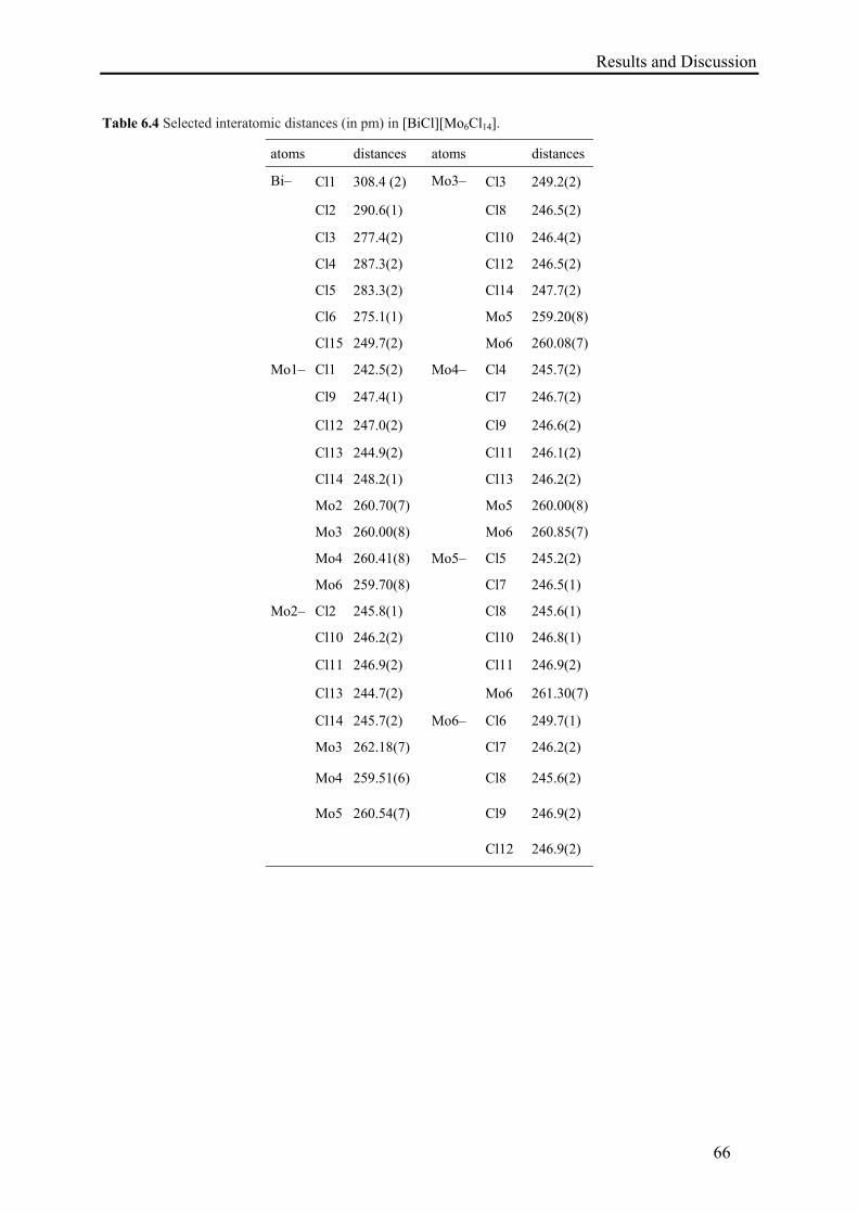
Results and Discussion
66
Table 6.4 Selected interatomic distances (in pm) in [BiCl][Mo6Cl14].
atoms distances atoms distances
Bi– Cl1 308.4 (2) Mo3–
Cl3 249.2(2)
Cl2 290.6(1) Cl8 246.5(2)
Cl3 277.4(2) Cl10 246.4(2)
Cl4 287.3(2) Cl12 246.5(2)
Cl5 283.3(2) Cl14 247.7(2)
Cl6 275.1(1) Mo5 259.20(8)
Cl15 249.7(2) Mo6 260.08(7)
Mo1–
Cl1 242.5(2) Mo4–
Cl4 245.7(2)
Cl9 247.4(1) Cl7 246.7(2)
Cl12 247.0(2) Cl9 246.6(2)
Cl13 244.9(2) Cl11 246.1(2)
Cl14 248.2(1) Cl13 246.2(2)
Mo2 260.70(7) Mo5 260.00(8)
Mo3 260.00(8) Mo6 260.85(7)
Mo4 260.41(8) Mo5–
Cl5 245.2(2)
Mo6 259.70(8) Cl7 246.5(1)
Mo2–
Cl2 245.8(1) Cl8 245.6(1)
Cl10 246.2(2) Cl10 246.8(1)
Cl11 246.9(2) Cl11 246.9(2)
Cl13 244.7(2) Mo6 261.30(7)
Cl14 245.7(2) Mo6–
Cl6 249.7(1)
Mo3 262.18(7) Cl7 246.2(2)
Mo4 259.51(6) Cl8 245.6(2)
Mo5 260.54(7) Cl9 246.9(2)
Cl12 246.9(2)
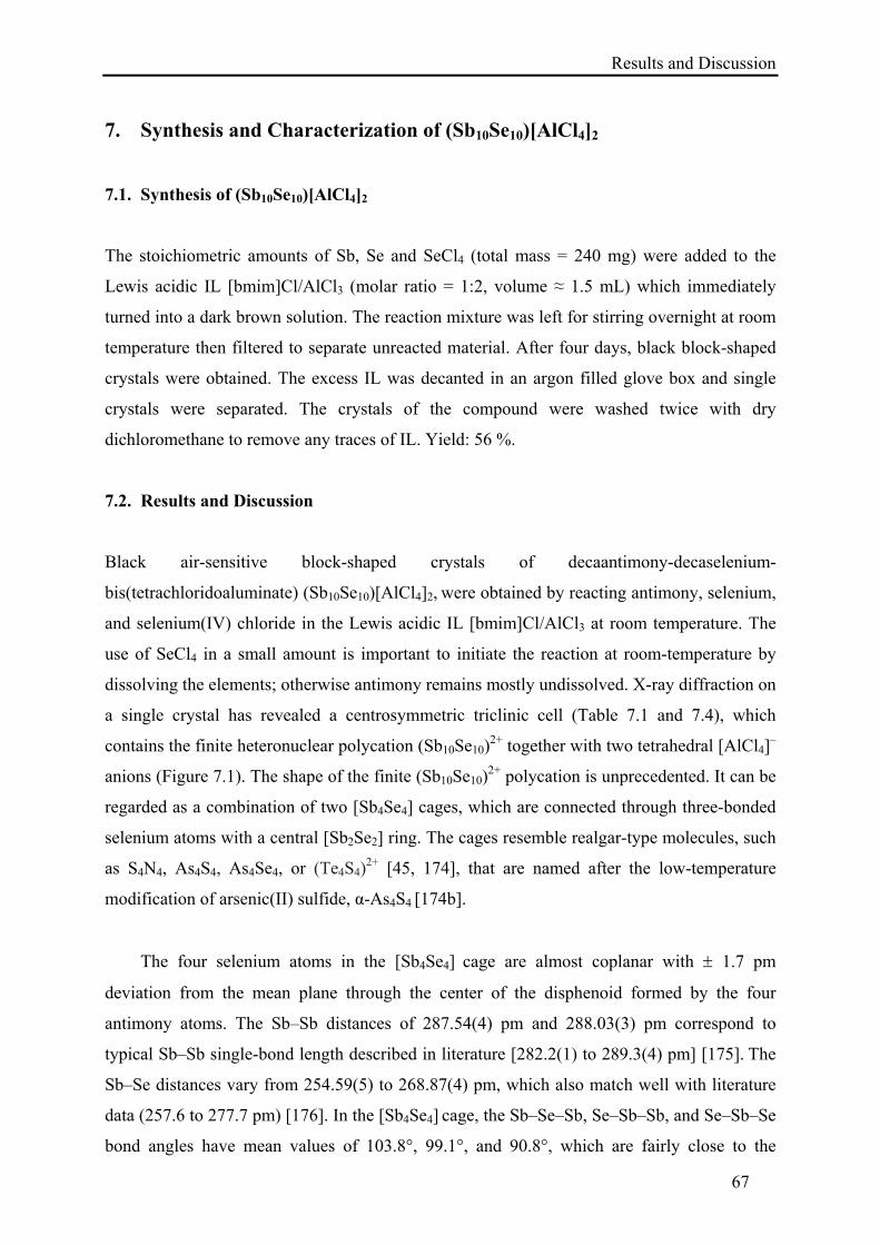
Results and Discussion
67
7. Synthesis and Characterization of (Sb10Se10)[AlCl4]2
7.1. Synthesis of (Sb10Se10)[AlCl4]2
The stoichiometric amounts of Sb, Se and SeCl4 (total mass = 240 mg) were added to the
Lewis acidic IL [bmim]Cl/AlCl3 (molar ratio = 1:2, volume ≈ 1.5 mL) which immediately
turned into a dark brown solution. The reaction mixture was left for stirring overnight at room
temperature then filtered to separate unreacted material. After four days, black block-shaped
crystals were obtained. The excess IL was decanted in an argon filled glove box and single
crystals were separated. The crystals of the compound were washed twice with dry
dichloromethane to remove any traces of IL. Yield: 56 %.
7.2. Results and Discussion
Black air-sensitive block-shaped crystals of decaantimony-decaselenium-
bis(tetrachloridoaluminate) (Sb10Se10)[AlCl4]2, were obtained by reacting antimony, selenium,
and selenium(IV) chloride in the Lewis acidic IL [bmim]Cl/AlCl3 at room temperature. The
use of SeCl4 in a small amount is important to initiate the reaction at room-temperature by
dissolving the elements; otherwise antimony remains mostly undissolved. X-ray diffraction on
a single crystal has revealed a centrosymmetric triclinic cell (Table 7.1 and 7.4), which
contains the finite heteronuclear polycation (Sb10Se10)2+ together with two tetrahedral [AlCl4]
–
anions (Figure 7.1). The shape of the finite (Sb10Se10)2+ polycation is unprecedented. It can be
regarded as a combination of two [Sb4Se4] cages, which are connected through three-bonded
selenium atoms with a central [Sb2Se2] ring. The cages resemble realgar-type molecules, such
as S4N4, As4S4, As4Se4, or (Te4S4)2+ [45, 174], that are named after the low-temperature
modification of arsenic(II) sulfide, α-As4S4 [174b].
The four selenium atoms in the [Sb4Se4] cage are almost coplanar with 1.7 pm
deviation from the mean plane through the center of the disphenoid formed by the four
antimony atoms. The Sb–Sb distances of 287.54(4) pm and 288.03(3) pm correspond to
typical Sb–Sb single-bond length described in literature [282.2(1) to 289.3(4) pm] [175]. The
Sb–Se distances vary from 254.59(5) to 268.87(4) pm, which also match well with literature
data (257.6 to 277.7 pm) [176]. In the [Sb4Se4] cage, the Sb–Se–Sb, Se–Sb–Sb, and Se–Sb–Se
bond angles have mean values of 103.8°, 99.1°, and 90.8°, which are fairly close to the
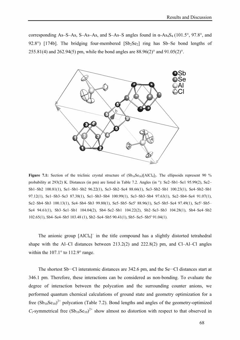
Results and Discussion
68
corresponding As–S–As, S–As–As, and S–As–S angles found in α-As4S4 (101.5°, 97.8°, and
92.8°) [174b]. The bridging four-membered [Sb2Se2] ring has Sb–Se bond lengths of
255.81(4) and 262.94(5) pm, while the bond angles are 88.96(2)° and 91.05(2)°.
Figure 7.1: Section of the triclinic crystal structure of (Sb10Se10)[AlCl4]2. The ellipsoids represent 90 %
probability at 293(2) K. Distances (in pm) are listed in Table 7.2. Angles (in °): Se2–Sb1–Se1 95.99(2), Se2–
Sb1–Sb2 100.81(1), Se1–Sb1–Sb2 96.22(1), Se3–Sb2–Se4 88.66(1), Se3–Sb2–Sb1 100.23(1), Se4–Sb2–Sb1
97.12(1), Se1–Sb3–Se3 87.38(1), Se1–Sb3–Sb4 100.99(1), Se3–Sb3–Sb4 97.63(1), Se2–Sb4–Se4 91.07(1),
Se2–Sb4–Sb3 100.13(1), Se4–Sb4–Sb3 99.80(1), Se5–Sb5–Se5' 88.96(1), Se5–Sb5–Se4 97.49(1), Se5'–Sb5–
Se4 94.61(1), Sb3–Se1–Sb1 104.04(2), Sb4–Se2–Sb1 104.22(2), Sb2–Se3–Sb3 104.28(1), Sb4–Se4–Sb2
102.65(1), Sb4–Se4–Sb5 103.48 (1), Sb2–Se4–Sb5 90.41(1), Sb5–Se5–Sb5' 91.04(1).
The anionic group [AlCl4]– in the title compound has a slightly distorted tetrahedral
shape with the Al–Cl distances between 213.2(2) and 222.8(2) pm, and Cl–Al–Cl angles
within the 107.1° to 112.9° range.
The shortest Sb···Cl interatomic distances are 342.6 pm, and the Se···Cl distances start at
346.1 pm. Therefore, these interactions can be considered as non-bonding. To evaluate the
degree of interaction between the polycation and the surrounding counter anions, we
performed quantum chemical calculations of ground state and geometry optimization for a
free (Sb10Se10)2+ polycation (Table 7.2). Bond lengths and angles of the geometry-optimized
Ci-symmetrical free (Sb10Se10)2+ show almost no distortion with respect to that observed in
Results and Discussion
69
(Sb10Se10)[AlCl4]2. The calculations also yield similar bonding energies of –61.7 and –61.3
eV for equilibrium and experimental (single point calculation) molecular shapes. Hence, the
polycation and its fragments are almost unstrained by packing or by ionic interactions with
the weakly coordinating [AlCl4]– anions in the crystal structure of (Sb10Se10)[AlCl4]2.
The Raman spectrum of a (Sb10Se10)[AlCl4]2 crystal showed several bands having
reasonable intensity in the characteristic range up to 350 cm–1 (Figure 7.2). Due to the low
symmetry of the unit cell, the vibrational spectrum consists of about 80 bands that strongly
overlap in the range from 150 to 200 cm–1, which hinders considerably the identification of
the bands. Only the band at 345 cm–1 is readily identified as the symmetric stretch mode of
[AlCl4]– anion [177], another weak band at about 160 cm–1
is likely hidden behind the strong
bands of the polycation.
Figure 7.2: Raman spectrum of a single crystal of (Sb10Se10)[AlCl4]2.
The extended (8–N)-rule by Mooser and Pearson [178], which generalizes the ideas of
Zintl about the bonding in polyanionic compounds, easily rationalizes the connectivity in the
polycation. The three-bonded selenium atom, Se4, should bear the positive charge, rendering
it a pseudo-element of group 15. On the other hand, the electronegativities, which determine
the attribution of oxidation states, draw an alternative picture, which is expressed by the
extended formula (SbII8SbIII
2Se–II10)
2+. As can be seen from the charge distribution pattern for
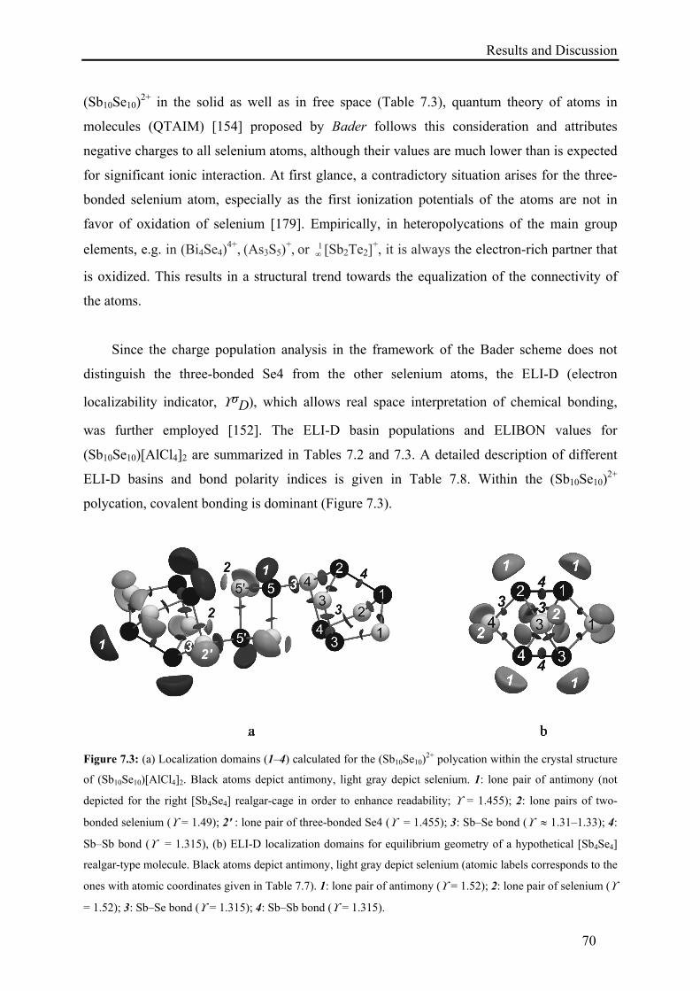
Results and Discussion
70
(Sb10Se10)2+ in the solid as well as in free space (Table 7.3), quantum theory of atoms in
molecules (QTAIM) [154] proposed by Bader follows this consideration and attributes
negative charges to all selenium atoms, although their values are much lower than is expected
for significant ionic interaction. At first glance, a contradictory situation arises for the three-
bonded selenium atom, especially as the first ionization potentials of the atoms are not in
favor of oxidation of selenium [179]. Empirically, in heteropolycations of the main group
elements, e.g. in (Bi4Se4)4+, (As3S5)
+, or 1 [Sb2Te2]
+, it is always the electron-rich partner that
is oxidized. This results in a structural trend towards the equalization of the connectivity of
the atoms.
Since the charge population analysis in the framework of the Bader scheme does not
distinguish the three-bonded Se4 from the other selenium atoms, the ELI-D (electron
localizability indicator, σD), which allows real space interpretation of chemical bonding,
was further employed [152]. The ELI-D basin populations and ELIBON values for
(Sb10Se10)[AlCl4]2 are summarized in Tables 7.2 and 7.3. A detailed description of different
ELI-D basins and bond polarity indices is given in Table 7.8. Within the (Sb10Se10)2+
polycation, covalent bonding is dominant (Figure 7.3).
Figure 7.3: (a) Localization domains (1–4) calculated for the (Sb10Se10)2+ polycation within the crystal structure
of (Sb10Se10)[AlCl4]2. Black atoms depict antimony, light gray depict selenium. 1: lone pair of antimony (not
depicted for the right [Sb4Se4] realgar-cage in order to enhance readability; = 1.455); 2: lone pairs of two-
bonded selenium ( = 1.49); 2' : lone pair of three-bonded Se4 ( = 1.455); 3: Sb–Se bond ( 1.31–1.33); 4:
Sb–Sb bond ( = 1.315), (b) ELI-D localization domains for equilibrium geometry of a hypothetical [Sb4Se4]
realgar-type molecule. Black atoms depict antimony, light gray depict selenium (atomic labels corresponds to the
ones with atomic coordinates given in Table 7.7). 1: lone pair of antimony ( = 1.52); 2: lone pair of selenium (
= 1.52); 3: Sb–Se bond ( = 1.315); 4: Sb–Sb bond ( = 1.315).
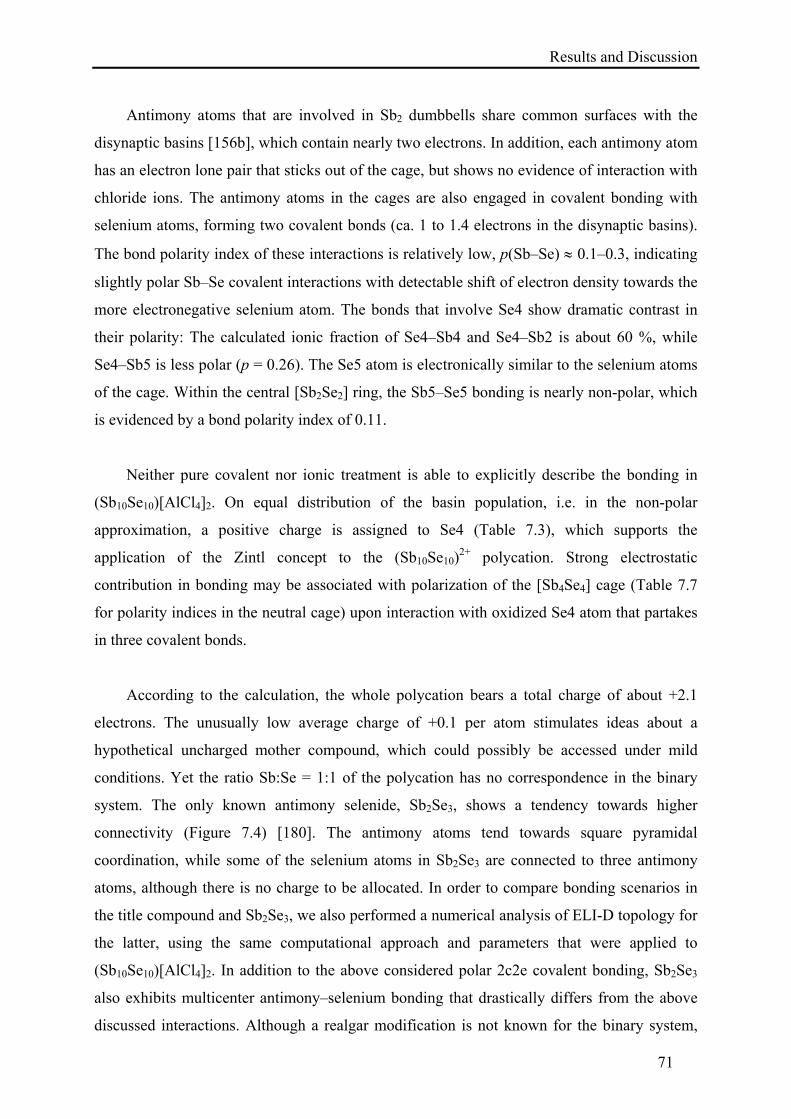
Results and Discussion
71
Antimony atoms that are involved in Sb2 dumbbells share common surfaces with the
disynaptic basins [156b], which contain nearly two electrons. In addition, each antimony atom
has an electron lone pair that sticks out of the cage, but shows no evidence of interaction with
chloride ions. The antimony atoms in the cages are also engaged in covalent bonding with
selenium atoms, forming two covalent bonds (ca. 1 to 1.4 electrons in the disynaptic basins).
The bond polarity index of these interactions is relatively low, p(Sb–Se) 0.1–0.3, indicating
slightly polar Sb–Se covalent interactions with detectable shift of electron density towards the
more electronegative selenium atom. The bonds that involve Se4 show dramatic contrast in
their polarity: The calculated ionic fraction of Se4–Sb4 and Se4–Sb2 is about 60 %, while
Se4–Sb5 is less polar (p = 0.26). The Se5 atom is electronically similar to the selenium atoms
of the cage. Within the central [Sb2Se2] ring, the Sb5–Se5 bonding is nearly non-polar, which
is evidenced by a bond polarity index of 0.11.
Neither pure covalent nor ionic treatment is able to explicitly describe the bonding in
(Sb10Se10)[AlCl4]2. On equal distribution of the basin population, i.e. in the non-polar
approximation, a positive charge is assigned to Se4 (Table 7.3), which supports the
application of the Zintl concept to the (Sb10Se10)2+ polycation. Strong electrostatic
contribution in bonding may be associated with polarization of the [Sb4Se4] cage (Table 7.7
for polarity indices in the neutral cage) upon interaction with oxidized Se4 atom that partakes
in three covalent bonds.
According to the calculation, the whole polycation bears a total charge of about +2.1
electrons. The unusually low average charge of +0.1 per atom stimulates ideas about a
hypothetical uncharged mother compound, which could possibly be accessed under mild
conditions. Yet the ratio Sb:Se = 1:1 of the polycation has no correspondence in the binary
system. The only known antimony selenide, Sb2Se3, shows a tendency towards higher
connectivity (Figure 7.4) [180]. The antimony atoms tend towards square pyramidal
coordination, while some of the selenium atoms in Sb2Se3 are connected to three antimony
atoms, although there is no charge to be allocated. In order to compare bonding scenarios in
the title compound and Sb2Se3, we also performed a numerical analysis of ELI-D topology for
the latter, using the same computational approach and parameters that were applied to
(Sb10Se10)[AlCl4]2. In addition to the above considered polar 2c2e covalent bonding, Sb2Se3
also exhibits multicenter antimony–selenium bonding that drastically differs from the above
discussed interactions. Although a realgar modification is not known for the binary system,
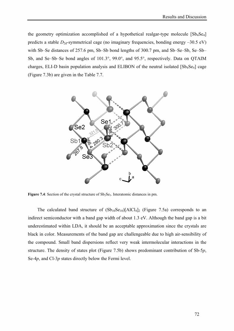
Results and Discussion
72
the geometry optimization accomplished of a hypothetical realgar-type molecule [Sb4Se4]
predicts a stable D2d-symmetrical cage (no imaginary frequencies, bonding energy –30.5 eV)
with Sb–Se distances of 257.6 pm, Sb–Sb bond lengths of 300.7 pm, and Sb–Se–Sb, Se–Sb–
Sb, and Se–Sb–Se bond angles of 101.3°, 99.0°, and 95.5°, respectively. Data on QTAIM
charges, ELI-D basin population analysis and ELIBON of the neutral isolated [Sb4Se4] cage
(Figure 7.3b) are given in the Table 7.7.
Figure 7.4: Section of the crystal structure of Sb2Se3. Interatomic distances in pm.
The calculated band structure of (Sb10Se10)[AlCl4]2 (Figure 7.5a) corresponds to an
indirect semiconductor with a band gap width of about 1.3 eV. Although the band gap is a bit
underestimated within LDA, it should be an acceptable approximation since the crystals are
black in color. Measurements of the band gap are challengeable due to high air-sensibility of
the compound. Small band dispersions reflect very weak intermolecular interactions in the
structure. The density of states plot (Figure 7.5b) shows predominant contribution of Sb-5p,
Se-4p, and Cl-3p states directly below the Fermi level.
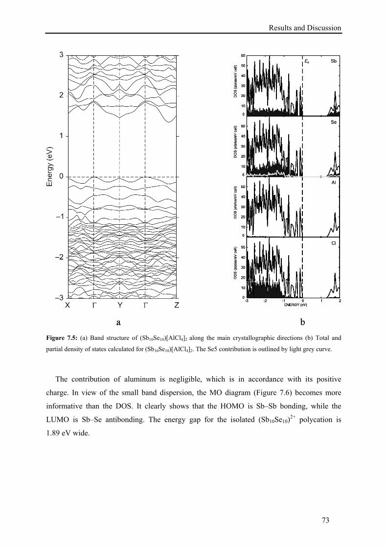
Results and Discussion
73
Figure 7.5: (a) Band structure of (Sb10Se10)[AlCl4]2 along the main crystallographic directions (b) Total and
partial density of states calculated for (Sb10Se10)[AlCl4]2. The Se5 contribution is outlined by light grey curve.
The contribution of aluminum is negligible, which is in accordance with its positive
charge. In view of the small band dispersion, the MO diagram (Figure 7.6) becomes more
informative than the DOS. It clearly shows that the HOMO is Sb–Sb bonding, while the
LUMO is Sb–Se antibonding. The energy gap for the isolated (Sb10Se10)2+ polycation is
1.89 eV wide.
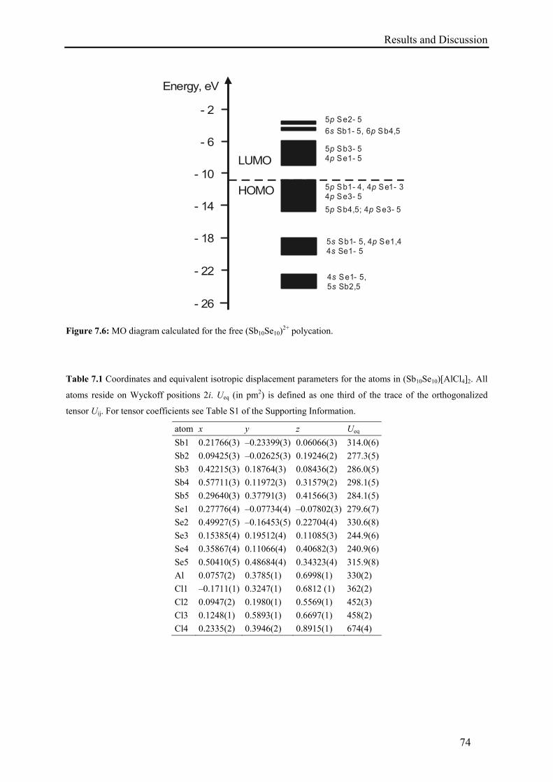
Results and Discussion
74
- 26
- 22
- 18
- 14
- 10
- 6
- 2
Energy, eV
HOMO
LUMO
4 -ss
Se1 5,5 Sb2,5
5 - 44 e1-ss
Sb1 5, S 5
p Se1,4
5 Sb4,5; 4 Se3- 5p p
5 Sb1- 4, 4 Se1- 34 Se3- 5p pp
5 Sb3- 54 Se1- 5pp
6 Sb1- 5, 6 Sb4,5s p5 Se2- 5p
Figure 7.6: MO diagram calculated for the free (Sb10Se10)
2+ polycation.
Table 7.1 Coordinates and equivalent isotropic displacement parameters for the atoms in (Sb10Se10)[AlCl4]2. All
atoms reside on Wyckoff positions 2i. Ueq (in pm2) is defined as one third of the trace of the orthogonalized
tensor Uij. For tensor coefficients see Table S1 of the Supporting Information.
atom x y z Ueq
Sb1 0.21766(3) –0.23399(3) 0.06066(3) 314.0(6)
Sb2 0.09425(3) –0.02625(3) 0.19246(2) 277.3(5)
Sb3 0.42215(3) 0.18764(3) 0.08436(2) 286.0(5)
Sb4 0.57711(3) 0.11972(3) 0.31579(2) 298.1(5)
Sb5 0.29640(3) 0.37791(3) 0.41566(3) 284.1(5)
Se1 0.27776(4) –0.07734(4) –0.07802(3) 279.6(7)
Se2 0.49927(5) –0.16453(5) 0.22704(4) 330.6(8)
Se3 0.15385(4) 0.19512(4) 0.11085(3) 244.9(6)
Se4 0.35867(4) 0.11066(4) 0.40682(3) 240.9(6)
Se5 0.50410(5) 0.48684(4) 0.34323(4) 315.9(8)
Al 0.0757(2) 0.3785(1) 0.6998(1) 330(2)
Cl1 –0.1711(1) 0.3247(1) 0.6812 (1) 362(2)
Cl2 0.0947(2) 0.1980(1) 0.5569(1) 452(3)
Cl3 0.1248(1) 0.5893(1) 0.6697(1) 458(2)
Cl4 0.2335(2) 0.3946(2) 0.8915(1) 674(4)
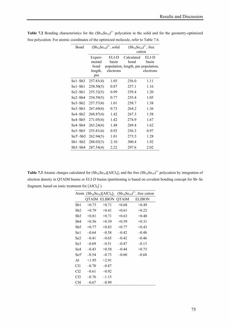
Results and Discussion
75
Table 7.2 Bonding characteristics for the (Sb10Se10)2+ polycation in the solid and for the geometry-optimized
free polycation. For atomic coordinates of the optimized molecule, refer to Table 7.6.
Bond (Sb10Se10)2+, solid (Sb10Se10)
2+, free cation
Experi-mental bond
length, pm
ELI-D basin
population, electrons
Calculated bond
length, pm
ELI-D basin
population, electrons
Se1–Sb3 257.81(4) 1.05 256.0 1.11
Se1–Sb1 258.50(5) 0.87 257.1 1.16
Se2–Sb1 255.32(5) 0.99 259.4 1.20
Se2–Sb4 254.59(5) 0.77 255.4 1.05
Se3–Sb2 257.57(4) 1.01 258.7 1.38
Se3–Sb3 267.69(4) 0.73 264.2 1.36
Se4–Sb2 268.87(4) 1.42 267.3 1.58
Se4–Sb5 271.05(4) 1.42 274.9 1.67
Se4–Sb4 263.24(4) 1.48 269.4 1.62
Se5–Sb5 255.81(4) 0.93 256.3 0.97
Se5'–Sb5 262.94(5) 1.01 273.5 1.28
Sb1–Sb2 288.03(3) 2.10 300.4 1.92
Sb3–Sb4 287.54(4) 2.22 297.6 2.02
Table 7.3 Atomic charges calculated for (Sb10Se10)[AlCl4]2 and the free (Sb10Se10)2+ polycation by integration of
electron density in QTAIM basins or ELI-D basins (partitioning is based on covalent bonding concept for Sb–Se
fragment, based on ionic treatment for [AlCl4]–).
Atom (Sb10Se10)[AlCl4]2 (Sb10Se10)2+, free cation
QTAIM ELIBON QTAIM ELIBON
Sb1 +0.73 +0.71 +0.68 +0.49
Sb2 +0.79 +0.41 +0.61 +0.22
Sb3 +0.81 +0.71 +0.63 +0.40
Sb4 +0.56 +0.39 +0.59 +0.31
Sb5 +0.77 +0.83 +0.77 +0.43
Se1 –0.64 –0.58 –0.42 –0.48
Se2 –0.41 –0.65 –0.42 –0.46
Se3 –0.69 –0.51 –0.47 –0.13
Se4 –0.43 +0.58 –0.44 +0.75
Se5' –0.54 –0.73 –0.60 –0.68
Al +1.95 +2.91
Cl1 –0.70 –0.87
Cl2 –0.61 –0.92
Cl3 –0.76 –1.15
Cl4 –0.67 –0.99
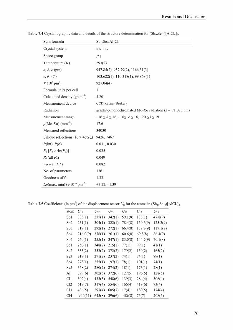
Results and Discussion
76
Table 7.4 Crystallographic data and details of the structure determination for (Sb10Se10)[AlCl4]2.
Sum formula Sb10Se10Al2Cl8
Crystal system triclinic
Space group P 1
Temperature (K) 293(2)
a, b, c (pm) 947.85(2), 957.79(2), 1166.31(3)
α, β, γ (°) 103.622(1), 110.318(1), 99.868(1)
V (106 pm3) 927.04(4)
Formula units per cell 1
Calculated density (g·cm–3) 4.20
Measurement device CCD Kappa (Bruker)
Radiation graphite-monochromated Mo-Kα radiation (λ = 71.073 pm)
Measurement range –16 ≤ h ≤ 16, –16≤ k ≤ 16, –20 ≤ l ≤ 19
μ(Mo-Kα) (mm–1) 17.6
Measured reflections 34030
Unique reflections (Fo > 4σ(Fo) 9426, 7467
R(int), R(σ) 0.031, 0.030
R1 [Fo > 4σ(Fo)] 0.035
R1 (all Fo) 0.049
wR2 (all Fo2) 0.082
No. of parameters 136
Goodness of fit 1.33
Δρ(max, min) (e·10–6 pm–3) +3.22, –1.39
Table 7.5 Coefficients (in pm2) of the displacement tensor Uij for the atoms in (Sb10Se10)[AlCl4]2.
atom U11 U22 U33 U12 U13 U23
Sb1 333(1) 235(1) 342(1) 59.1(8) 138(1) 47.8(9)
Sb2 251(1) 304(1) 322(1) 78.4(8) 150.6(9) 125.2(9)
Sb3 319(1) 292(1) 272(1) 66.4(8) 139.7(9) 117.1(8)
Sb4 216.0(9) 376(1) 261(1) 60.6(8) 69.8(8) 86.4(9)
Sb5 260(1) 255(1) 347(1) 83.0(8) 144.7(9) 70.1(8)
Se1 250(1) 348(2) 215(1) 77(1) 99(1) 41(1)
Se2 335(2) 353(2) 372(2) 179(2) 150(2) 165(2)
Se3 219(1) 271(2) 237(2) 74(1) 74(1) 89(1)
Se4 278(1) 255(1) 197(1) 78(1) 101(1) 74(1)
Se5 368(2) 280(2) 274(2) 18(1) 173(1) 28(1)
Al 379(6) 302(5) 372(6) 127(5) 196(5) 128(5)
Cl1 302(4) 433(5) 548(6) 139(3) 284(4) 306(4)
Cl2 619(7) 317(4) 554(6) 166(4) 418(6) 73(4)
Cl3 436(5) 297(4) 605(7) 17(4) 189(5) 174(4)
Cl4 944(11) 645(8) 396(6) 486(8) 76(7) 208(6)
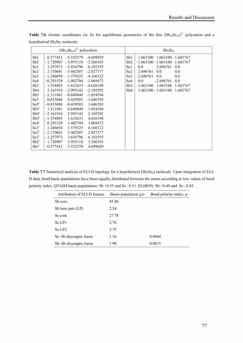
Results and Discussion
77
Table 7.6 Atomic coordinates (in Å) for equilibrium geometries of the free (Sb10Se10)2+ polycation and a
hypothetical Sb4Se4 molecule.
(Sb10Se10)2+ polycation Sb4Se4
Sb1 Sb2 Se1 Se2 Se3 Se4 Sb3 Sb4 Sb5 Se5 Se5' Sb5' Sb4' Sb3' Se4' Se3' Se2' Se1' Sb2' Sb1'
0.377431 –5.552579 –4.699029 –1.720907 –3.955118 –3.260103 1.257973 –3.654796 –6.192555 2.170681 –5.442507 –2.827377 –1.246054 –1.579325 –4.166122 –0.291529 –3.402704 –1.069472 1.354883 –1.632633 –4.626190 2.161910 –2.993142 –2.105292 –1.311801 –0.849849 –1.054394 0.833088 0.439503 –1.606705 –0.833088 –0.439503 1.606705 1.311801 0.849849 1.054394 –2.161910 2.993142 2.105292 –1.354883 1.632633 4.626190 0.291529 3.402704 1.069472 1.246054 1.579325 4.166122 –2.170681 5.442507 2.827377 –1.257973 3.654796 6.192555 1.720907 3.955118 3.260103 –0.377431 5.552579 4.699029
Sb1 Sb2 Se1 Se2 Se3 Se4 Sb3 Sb4
1.063100 1.063100 –1.683767 –1.063100 –1.063100 –1.683767 0.0 2.696761 0.0 2.696761 0.0 0.0 –2.696761 0.0 0.0 0.0 –2.696761 0.0 –1.063100 1.063100 1.683767 1.063100 –1.063100 1.683767
Table 7.7 Numerical analysis of ELI-D topology for a hypothetical [Sb4Se4] molecule. Upon integration of ELI-
D data, bond basin populations have been equally distributed between the atoms according to low values of bond
polarity index. QTAIM basin populations: Sb +0.55 and Se –0.51. ELIBON: Sb +0.49 and Se –0.45.
Attribution of ELI-D feature Basin population q/e– Bond polarity index, p
Sb core 45.86
Sb lone pair (LP) 2.54
Se core 27.78
Se LP1 2.76
Se LP2 2.75
Se–Sb disynaptic basin 1.16 0.0044
Sb–Sb disynaptic basin 1.90 0.0015
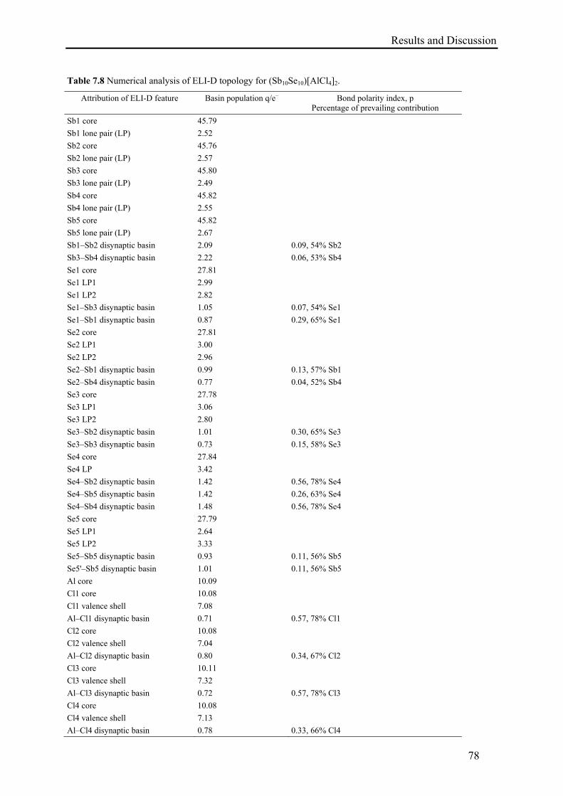
Results and Discussion
78
Table 7.8 Numerical analysis of ELI-D topology for (Sb10Se10)[AlCl4]2.
Attribution of ELI-D feature Basin population q/e– Bond polarity index, p Percentage of prevailing contribution
Sb1 core 45.79
Sb1 lone pair (LP) 2.52
Sb2 core 45.76
Sb2 lone pair (LP) 2.57
Sb3 core 45.80
Sb3 lone pair (LP) 2.49
Sb4 core 45.82
Sb4 lone pair (LP) 2.55
Sb5 core 45.82
Sb5 lone pair (LP) 2.67
Sb1–Sb2 disynaptic basin 2.09 0.09, 54% Sb2
Sb3–Sb4 disynaptic basin 2.22 0.06, 53% Sb4
Se1 core 27.81
Se1 LP1 2.99
Se1 LP2 2.82
Se1–Sb3 disynaptic basin 1.05 0.07, 54% Se1
Se1–Sb1 disynaptic basin 0.87 0.29, 65% Se1
Se2 core 27.81
Se2 LP1 3.00
Se2 LP2 2.96
Se2–Sb1 disynaptic basin 0.99 0.13, 57% Sb1
Se2–Sb4 disynaptic basin 0.77 0.04, 52% Sb4
Se3 core 27.78
Se3 LP1 3.06
Se3 LP2 2.80
Se3–Sb2 disynaptic basin 1.01 0.30, 65% Se3
Se3–Sb3 disynaptic basin 0.73 0.15, 58% Se3
Se4 core 27.84
Se4 LP 3.42
Se4–Sb2 disynaptic basin 1.42 0.56, 78% Se4
Se4–Sb5 disynaptic basin 1.42 0.26, 63% Se4
Se4–Sb4 disynaptic basin 1.48 0.56, 78% Se4
Se5 core 27.79
Se5 LP1 2.64
Se5 LP2 3.33
Se5–Sb5 disynaptic basin 0.93 0.11, 56% Sb5
Se5'–Sb5 disynaptic basin 1.01 0.11, 56% Sb5
Al core 10.09
Cl1 core 10.08
Cl1 valence shell 7.08
Al–Cl1 disynaptic basin 0.71 0.57, 78% Cl1
Cl2 core 10.08
Cl2 valence shell 7.04
Al–Cl2 disynaptic basin 0.80 0.34, 67% Cl2
Cl3 core 10.11
Cl3 valence shell 7.32
Al–Cl3 disynaptic basin 0.72 0.57, 78% Cl3
Cl4 core 10.08
Cl4 valence shell 7.13
Al–Cl4 disynaptic basin 0.78 0.33, 66% Cl4
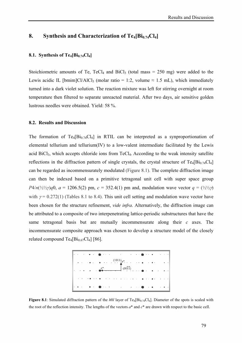
Results and Discussion
79
8. Synthesis and Characterization of Te4[Bi0.74Cl4]
8.1. Synthesis of Te4[Bi0.74Cl4]
Stoichiometric amounts of Te, TeCl4 and BiCl3 (total mass = 250 mg) were added to the
Lewis acidic IL [bmim]Cl/AlCl3 (molar ratio = 1:2, volume ≈ 1.5 mL), which immediately
turned into a dark violet solution. The reaction mixture was left for stirring overnight at room
temperature then filtered to separate unreacted material. After two days, air sensitive golden
lustrous needles were obtained. Yield: 58 %.
8.2. Results and Discussion
The formation of Te4[Bi0.74Cl4] in RTIL can be interpreted as a synproportionation of
elemental tellurium and tellurium(IV) to a low-valent intermediate facilitated by the Lewis
acid BiCl3, which accepts chloride ions from TeCl4. According to the weak intensity satellite
reflections in the diffraction pattern of single crystals, the crystal structure of Te4[Bi0.74Cl4]
can be regarded as incommensurately modulated (Figure 8.1). The complete diffraction image
can then be indexed based on a primitive tetragonal unit cell with super space group
P4/n(½½γ)q0, a = 1206.5(2) pm, c = 352.4(1) pm and, modulation wave vector q = (½½)
with = 0.272(1) (Tables 8.1 to 8.4). This unit cell setting and modulation wave vector have
been chosen for the structure refinement, vide infra. Alternatively, the diffraction image can
be attributed to a composite of two interpenetrating lattice-periodic substructures that have the
same tetragonal basis but are mutually incommensurate along their c axes. The
incommensurate composite approach was chosen to develop a structure model of the closely
related compound Te4[Bi0.67Cl4] [86].
Figure 8.1: Simulated diffraction pattern of the h0l layer of Te4[Bi0.74Cl4]. Diameter of the spots is scaled with
the root of the reflection intensity. The lengths of the vectors a* and c* are drawn with respect to the basic cell.
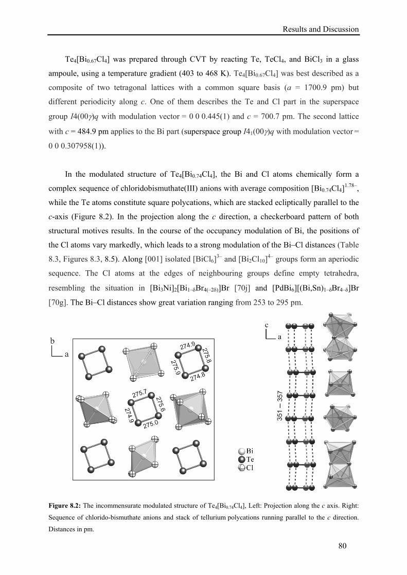
Results and Discussion
80
Te4[Bi0.67Cl4] was prepared through CVT by reacting Te, TeCl4, and BiCl3 in a glass
ampoule, using a temperature gradient (403 to 468 K). Te4[Bi0.67Cl4] was best described as a
composite of two tetragonal lattices with a common square basis (a = 1700.9 pm) but
different periodicity along c. One of them describes the Te and Cl part in the superspace
group I4(00)q with modulation vector = 0 0 0.445(1) and c = 700.7 pm. The second lattice
with c = 484.9 pm applies to the Bi part (superspace group I41(00)q with modulation vector =
0 0 0.307958(1)).
In the modulated structure of Te4[Bi0.74Cl4], the Bi and Cl atoms chemically form a
complex sequence of chloridobismuthate(III) anions with average composition [Bi0.74Cl4]1.78–,
while the Te atoms constitute square polycations, which are stacked ecliptically parallel to the
c-axis (Figure 8.2). In the projection along the c direction, a checkerboard pattern of both
structural motives results. In the course of the occupancy modulation of Bi, the positions of
the Cl atoms vary markedly, which leads to a strong modulation of the Bi–Cl distances (Table
8.3, Figures 8.3, 8.5). Along [001] isolated [BiCl6]3– and [Bi2Cl10]
4– groups form an aperiodic
sequence. The Cl atoms at the edges of neighbouring groups define empty tetrahedra,
resembling the situation in [Bi3Ni]2[Bi1–Br4(–2)]Br [70j] and [PdBi6][(Bi,Sn)1–δBr4–δ]Br
[70g]. The Bi–Cl distances show great variation ranging from 253 to 295 pm.
Figure 8.2: The incommensurate modulated structure of Te4[Bi0.74Cl4], Left: Projection along the c axis. Right:
Sequence of chlorido-bismuthate anions and stack of tellurium polycations running parallel to the c direction.
Distances in pm.
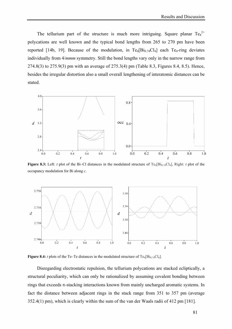
Results and Discussion
81
The tellurium part of the structure is much more intriguing. Square planar Te42+
polycations are well known and the typical bond lengths from 265 to 270 pm have been
reported [14b, 19]. Because of the modulation, in Te4[Bi0.74Cl4] each Te4-ring deviates
individually from 4/mmm symmetry. Still the bond lengths vary only in the narrow range from
274.8(3) to 275.9(3) pm with an average of 275.3(4) pm (Table 8.3, Figures 8.4, 8.5). Hence,
besides the irregular distortion also a small overall lengthening of interatomic distances can be
stated.
Figure 8.3: Left: t plot of the Bi–Cl distances in the modulated structure of Te4[Bi0.74Cl4], Right: t plot of the
occupancy modulation for Bi along c.
Figure 8.4: t plots of the Te–Te distances in the modulated structure of Te4[Bi0.74Cl4].
Disregarding electrostatic repulsion, the tellurium polycations are stacked ecliptically, a
structural peculiarity, which can only be rationalized by assuming covalent bonding between
rings that exceeds -stacking interactions known from mainly uncharged aromatic systems. In
fact the distance between adjacent rings in the stack range from 351 to 357 pm (average
352.4(1) pm), which is clearly within the sum of the van der Waals radii of 412 pm [181].
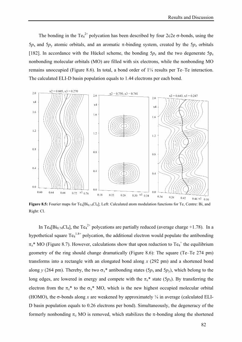
Results and Discussion
82
The bonding in the Te42+ polycation has been described by four 2c2e -bonds, using the
5px and 5py atomic orbitals, and an aromatic -binding system, created by the 5pz orbitals
[182]. In accordance with the Hückel scheme, the bonding 5pz and the two degenerate 5pz
nonbonding molecular orbitals (MO) are filled with six electrons, while the nonbonding MO
remains unoccupied (Figure 8.6). In total, a bond order of 1¼ results per Te–Te interaction.
The calculated ELI-D basin population equals to 1.44 electrons per each bond.
Figure 8.5: Fourier maps for Te4[Bi0.74Cl4]; Left: Calculated atom modulation functions for Te, Centre: Bi, and
Right: Cl.
In Te4[Bi0.74Cl4], the Te42+ polycations are partially reduced (average charge +1.78). In a
hypothetical square Te41.8+ polycation, the additional electron would populate the antibonding
z* MO (Figure 8.7). However, calculations show that upon reduction to Te4+ the equilibrium
geometry of the ring should change dramatically (Figure 8.6): The square (Te–Te 274 pm)
transforms into a rectangle with an elongated bond along x (292 pm) and a shortened bond
along y (264 pm). Thereby, the two x* antibonding states (5px and 5py), which belong to the
long edges, are lowered in energy and compete with the z* state (5pz). By transferring the
electron from the z* to the x* MO, which is the new highest occupied molecular orbital
(HOMO), the -bonds along x are weakened by approximately ¼ in average (calculated ELI-
D basin population equals to 0.26 electrons per bond). Simultaneously, the degeneracy of the
formerly nonbonding z MO is removed, which stabilizes the -bonding along the shortened
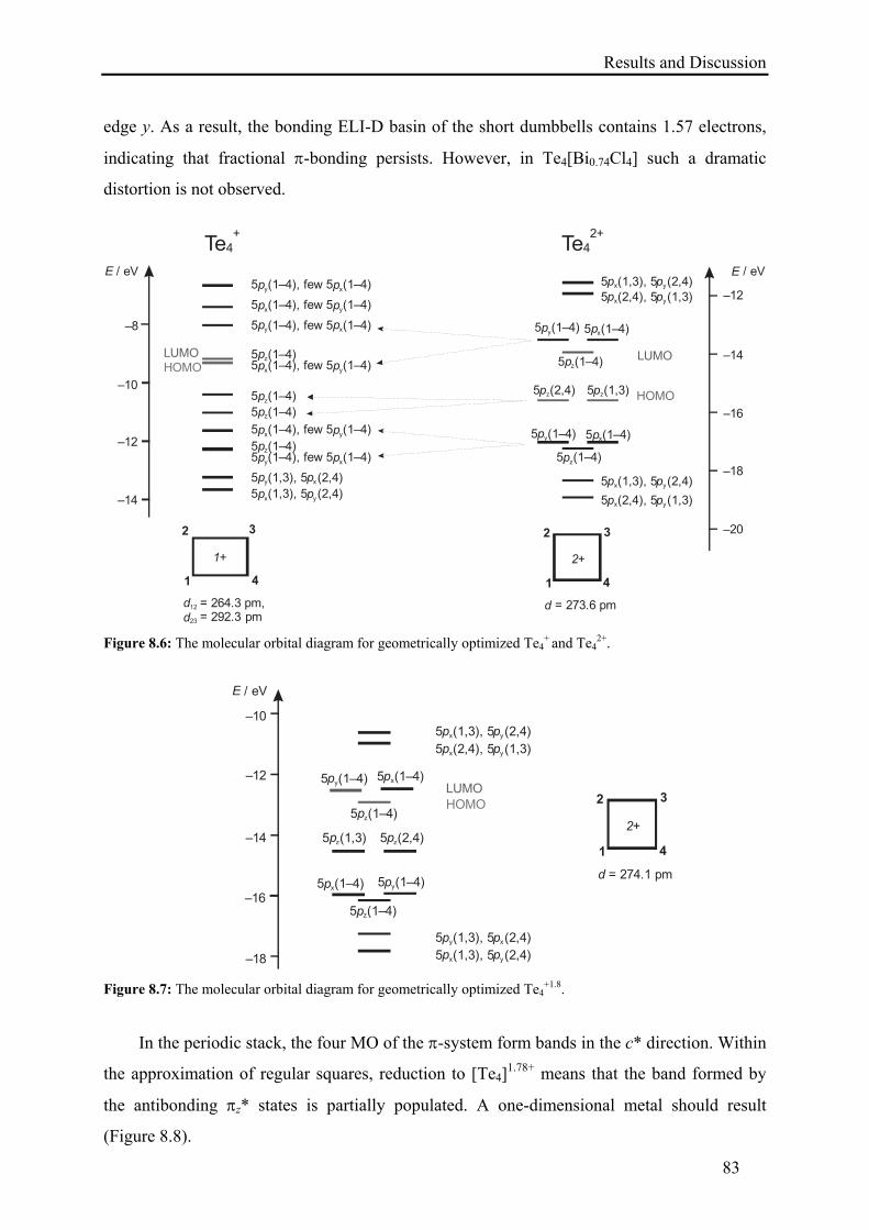
Results and Discussion
83
edge y. As a result, the bonding ELI-D basin of the short dumbbells contains 1.57 electrons,
indicating that fractional -bonding persists. However, in Te4[Bi0.74Cl4] such a dramatic
distortion is not observed.
5 (1,3), 5 (2,4)p px y
5 (1,3), 5 (2,4)p py x
5 (1–4), few 5 (1–4)p py x
5 (1–4)pz
5 (1–4), few 5 (1–4)p px y
5 (1–4)pz
5 (1–4)pz
5 (1–4), few 5 (1–4)p px y
5 (1–4)pz
5 (1–4), few 5 (1–4)p py x
5 (1–4), few 5 (1–4)p px y
5 (1–4), few 5 (1–4)p py x
HOMOLUMO
5 (2,4), 5 (1,3)p px y
5 (1,3), 5 (2,4)p px y
5 (1–4)pz
5 (1–4)py 5 (1–4)px
5 (2,4)pz 5 (1,3)pz
5 (1–4)pz
5 (1–4)px5 (1–4)py
5 (2,4), 5 (1,3)p px y
5 (1,3), 5 (2,4)p px y
HOMO
LUMO
Te42+
Te4+
1
2 3
4
2+
d = 273.6 pm
1
2 3
4
1+
d12
3
= 264.3 pm, 92.3d2 = 2 pm
–10
–12
–12
–14
–16
–18
–20
E / eV E / eV
–8
–14
Figure 8.6: The molecular orbital diagram for geometrically optimized Te4+ and Te4
2+.
5 (1,3), 5 (2,4)p px y
5 (1,3), 5 (2,4)p py x
5 (1–4)pz
5 (1–4)px
5 (1,3)pz 5 (2,4)pz
5 (1–4)pz
5 (2,4), 5 (1,3)p px y
5 (1,3), 5 (2,4)p px y
5 (1–4)py
5 (1–4)py5 (1–4)px
HOMOLUMO
1
2 3
4
2+
d = 274.1 pm
–10
–12
–14
E / eV
–16
–18 Figure 8.7: The molecular orbital diagram for geometrically optimized Te4
+1.8.
In the periodic stack, the four MO of the -system form bands in the c* direction. Within
the approximation of regular squares, reduction to [Te4]1.78+ means that the band formed by
the antibonding z* states is partially populated. A one-dimensional metal should result
(Figure 8.8).
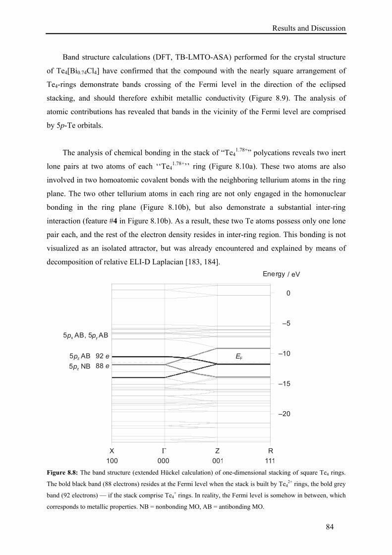
Results and Discussion
84
Band structure calculations (DFT, TB-LMTO-ASA) performed for the crystal structure
of Te4[Bi0.74Cl4] have confirmed that the compound with the nearly square arrangement of
Te4-rings demonstrate bands crossing of the Fermi level in the direction of the eclipsed
stacking, and should therefore exhibit metallic conductivity (Figure 8.9). The analysis of
atomic contributions has revealed that bands in the vicinity of the Fermi level are comprised
by 5p-Te orbitals.
The analysis of chemical bonding in the stack of “Te41.78+” polycations reveals two inert
lone pairs at two atoms of each ‘‘Te41.78+’’ ring (Figure 8.10a). These two atoms are also
involved in two homoatomic covalent bonds with the neighboring tellurium atoms in the ring
plane. The two other tellurium atoms in each ring are not only engaged in the homonuclear
bonding in the ring plane (Figure 8.10b), but also demonstrate a substantial inter-ring
interaction (feature #4 in Figure 8.10b). As a result, these two Te atoms possess only one lone
pair each, and the rest of the electron density resides in inter-ring region. This bonding is not
visualized as an isolated attractor, but was already encountered and explained by means of
decomposition of relative ELI-D Laplacian [183, 184].
X Z R
–20
–15
–10
–5
0
Energy / eV
100 000 001 111
88 e92 e
5 NBpz
5 ABpz
5 AB, 5px py AB
EF
Figure 8.8: The band structure (extended Hückel calculation) of one-dimensional stacking of square Te4 rings.
The bold black band (88 electrons) resides at the Fermi level when the stack is built by Te42+ rings, the bold grey
band (92 electrons) — if the stack comprise Te4+ rings. In reality, the Fermi level is somehow in between, which
corresponds to metallic properties. NB = nonbonding MO, AB = antibonding MO.
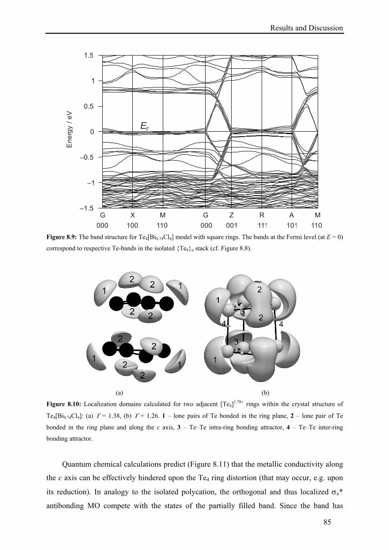
Results and Discussion
85
1
1.5
–1.5
–1
–0.5
0
0.5
G X M G Z R A M
En
erg
y /
eV
000 100 110 000 001 111 101 110
EF
Figure 8.9: The band structure for Te4[Bi0.74Cl4] model with square rings. The bands at the Fermi level (at E = 0)
correspond to respective Te-bands in the isolated {Te4}n stack (cf. Figure 8.8).
(a) (b)
Figure 8.10: Localization domains calculated for two adjacent [Te4]1.78+ rings within the crystal structure of
Te4[Bi0.74Cl4]: (a) = 1.38, (b) = 1.26. 1 – lone pairs of Te bonded in the ring plane, 2 – lone pair of Te
bonded in the ring plane and along the c axis, 3 – Te–Te intra-ring bonding attractor, 4 – Te–Te inter-ring
bonding attractor.
Quantum chemical calculations predict (Figure 8.11) that the metallic conductivity along
the c axis can be effectively hindered upon the Te4 ring distortion (that may occur, e.g. upon
its reduction). In analogy to the isolated polycation, the orthogonal and thus localized x*
antibonding MO compete with the states of the partially filled band. Since the band has
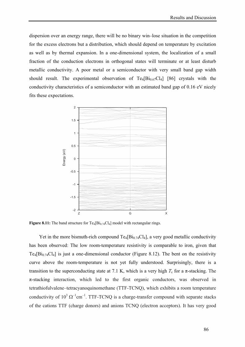
Results and Discussion
86
dispersion over an energy range, there will be no binary win–lose situation in the competition
for the excess electrons but a distribution, which should depend on temperature by excitation
as well as by thermal expansion. In a one-dimensional system, the localization of a small
fraction of the conduction electrons in orthogonal states will terminate or at least disturb
metallic conductivity. A poor metal or a semiconductor with very small band gap width
should result. The experimental observation of Te4[Bi0.67Cl4] [86] crystals with the
conductivity characteristics of a semiconductor with an estimated band gap of 0.16 eV nicely
fits these expectations.
-2
-1.5
-1
-0.5
0
0.5
1
1.5
2
Z G X
En
ergy
(e
V)
Figure 8.11: The band structure for Te4[Bi0.74Cl4] model with rectangular rings.
Yet in the more bismuth-rich compound Te4[Bi0.74Cl4], a very good metallic conductivity
has been observed: The low room-temperature resistivity is comparable to iron, given that
Te4[Bi0.74Cl4] is just a one-dimensional conductor (Figure 8.12). The bent on the resistivity
curve above the room-temperature is not yet fully understood. Surprisingly, there is a
transition to the superconducting state at 7.1 K, which is a very high Tc for a π-stacking. The
π-stacking interaction, which led to the first organic conductors, was observed in
tetrathiofulvalene–tetracyanoquinomethane (TTF-TCNQ), which exhibits a room temperature
conductivity of 103 –1cm–1. TTF-TCNQ is a charge-transfer compound with separate stacks
of the cations TTF (charge donors) and anions TCNQ (electron acceptors). It has very good
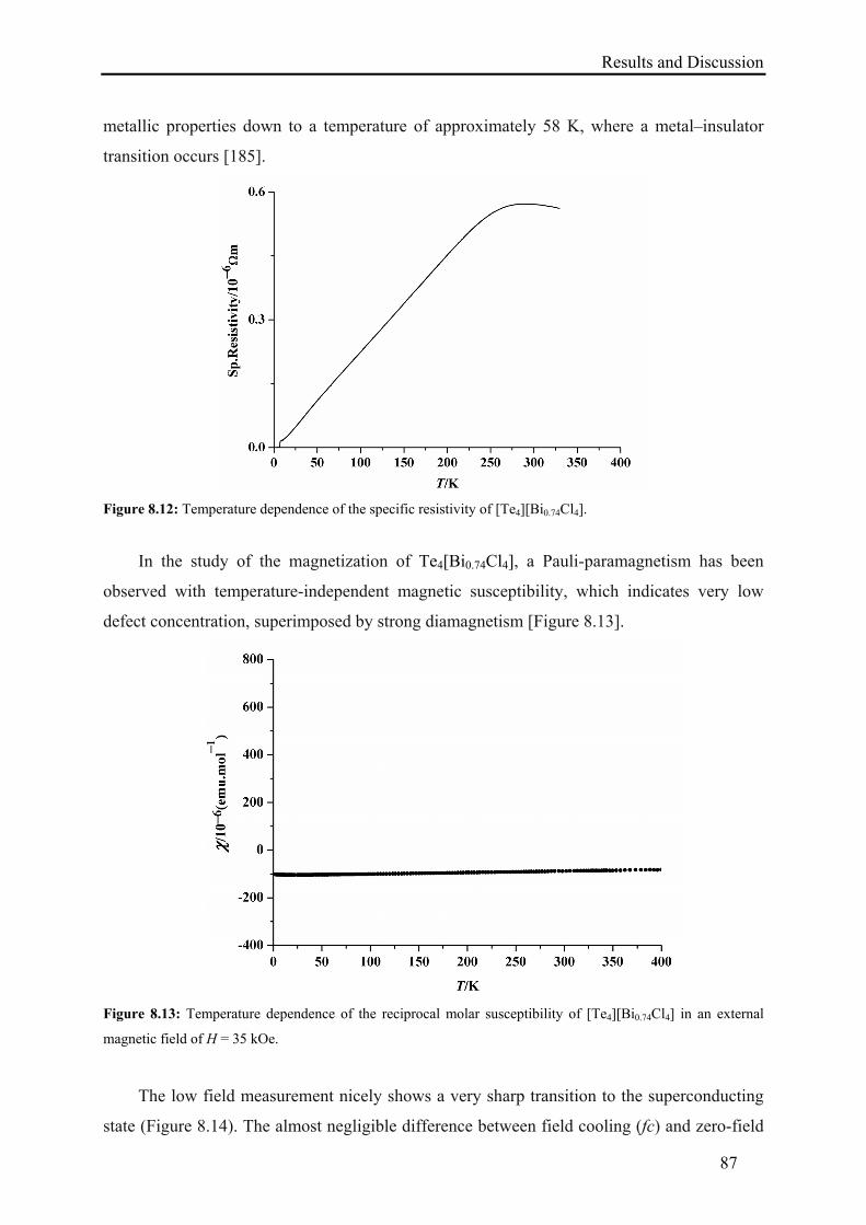
Results and Discussion
87
metallic properties down to a temperature of approximately 58 K, where a metal–insulator
transition occurs [185].
Figure 8.12: Temperature dependence of the specific resistivity of [Te4][Bi0.74Cl4].
In the study of the magnetization of Te4[Bi0.74Cl4], a Pauli-paramagnetism has been
observed with temperature-independent magnetic susceptibility, which indicates very low
defect concentration, superimposed by strong diamagnetism [Figure 8.13].
Figure 8.13: Temperature dependence of the reciprocal molar susceptibility of [Te4][Bi0.74Cl4] in an external
magnetic field of H = 35 kOe.
The low field measurement nicely shows a very sharp transition to the superconducting
state (Figure 8.14). The almost negligible difference between field cooling (fc) and zero-field
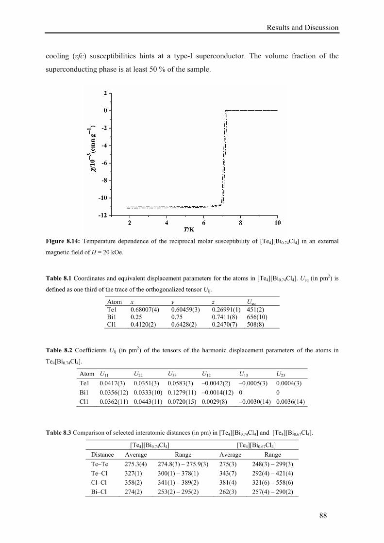
Results and Discussion
88
cooling (zfc) susceptibilities hints at a type-I superconductor. The volume fraction of the
superconducting phase is at least 50 % of the sample.
Figure 8.14: Temperature dependence of the reciprocal molar susceptibility of [Te4][Bi0.74Cl4] in an external
magnetic field of H = 20 kOe.
Table 8.1 Coordinates and equivalent displacement parameters for the atoms in [Te4][Bi0.74Cl4]. Ueq (in pm2) is
defined as one third of the trace of the orthogonalized tensor Uij.
Atom x y z Ueq Te1 0.68007(4) 0.60459(3) 0.26991(1) 451(2) Bi1 0.25 0.75 0.7411(8) 656(10) Cl1 0.4120(2) 0.6428(2) 0.2470(7) 508(8)
Table 8.2 Coefficients Uij (in pm2) of the tensors of the harmonic displacement parameters of the atoms in
Te4[Bi0.74Cl4].
Atom U11 U22 U33 U12 U13 U23
Te1 0.0417(3) 0.0351(3) 0.0583(3) –0.0042(2) –0.0005(3) 0.0004(3)
Bi1 0.0356(12) 0.0333(10) 0.1279(11) –0.0014(12) 0 0
Cl1 0.0362(11) 0.0443(11) 0.0720(15) 0.0029(8) –0.0030(14) 0.0036(14)
Table 8.3 Comparison of selected interatomic distances (in pm) in [Te4][Bi0.74Cl4] and [Te4][Bi0.67Cl4].
[Te4][Bi0.74Cl4] [Te4][Bi0.67Cl4]
Distance Average Range Average Range
Te–Te 275.3(4) 274.8(3) – 275.9(3) 275(3) 248(3) – 299(3)
Te–Cl 327(1) 300(1) – 378(1) 343(7) 292(4) – 421(4)
Cl–Cl 358(2) 341(1) – 389(2) 381(4) 321(6) – 558(6)
Bi–Cl 274(2) 253(2) – 295(2) 262(3) 257(4) – 290(2)
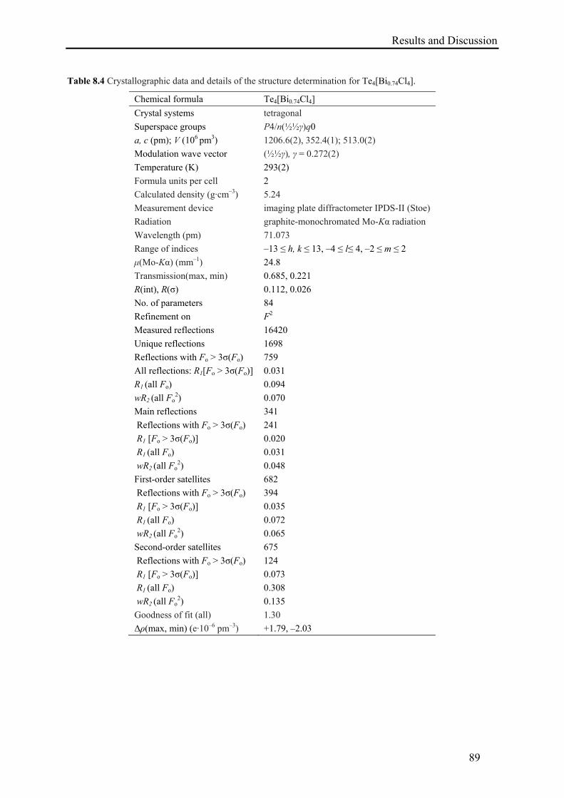
Results and Discussion
89
Table 8.4 Crystallographic data and details of the structure determination for Te4[Bi0.74Cl4].
Chemical formula Te4[Bi0.74Cl4]
Crystal systems tetragonal
Superspace groups P4/n(½½γ)q0
a, c (pm); V (106 pm3) 1206.6(2), 352.4(1); 513.0(2)
Modulation wave vector (½½γ), γ = 0.272(2)
Temperature (K) 293(2)
Formula units per cell 2
Calculated density (g·cm–3) 5.24
Measurement device imaging plate diffractometer IPDS-II (Stoe)
Radiation graphite-monochromated Mo-Kα radiation
Wavelength (pm) 71.073
Range of indices –13 ≤ h, k ≤ 13, –4 ≤ l≤ 4, –2 ≤ m ≤ 2
μ(Mo-Kα) (mm–1) 24.8
Transmission(max, min) 0.685, 0.221
R(int), R(σ) 0.112, 0.026
No. of parameters 84
Refinement on F2
Measured reflections 16420
Unique reflections 1698
Reflections with Fo > 3σ(Fo) 759
All reflections: R1[Fo > 3σ(Fo)] 0.031
R1 (all Fo) 0.094
wR2 (all Fo2) 0.070
Main reflections 341
Reflections with Fo > 3σ(Fo) 241
R1 [Fo > 3σ(Fo)] 0.020
R1 (all Fo) 0.031
wR2 (all Fo2) 0.048
First-order satellites 682
Reflections with Fo > 3σ(Fo) 394
R1 [Fo > 3σ(Fo)] 0.035
R1 (all Fo) 0.072
wR2 (all Fo2) 0.065
Second-order satellites 675
Reflections with Fo > 3σ(Fo) 124
R1 [Fo > 3σ(Fo)] 0.073
R1 (all Fo) 0.308
wR2 (all Fo2) 0.135
Goodness of fit (all) 1.30
Δρ(max, min) (e·10–6 pm–3) +1.79, –2.03
Conclusion and Outlook
90
9. Conclusion and Outlook
Main group polycations and transition metal clusters had traditionally been synthesized via
high-temperature routes by performing reactions in melts or by CTR, at room-temperature or
lower temperature by using so-called superacid solvents, and at room-temperature in
benzene–GaX3 media. Considering the major problems associated with higher temperature
routes (e.g. long annealing time, risk of product decomposition, and low yield) and taking into
account the toxicity of benzene and liquid SO2 in room-temperature or lower temperature
synthesis, a soft and sustainable chemical approach has been developed, employing a Lewis-
acidic IL [bmim]Cl/AlCl3. This new alternative reaction medium has proven to be an
excellent solvent system for the single–step synthesis of main group polycations and
transition metal clusters. X-ray diffraction and Raman spectroscopy have been used for the
structural characterization of the isolated compounds. Physical properties and quantum
chemical calculations of some of the compounds have also been carried out.
This new synthetic scheme is based on the extraordinarily high solubility of metal
halogenides in Lewis acidic systems, which renders pseudo-melt behavior to the saturated
solution. Thus, it has been possible to repeat, at room temperature, several of the reactions
previously performed in melts or by CTR at substantially higher temperature. Although, in the
beginning, it was quite challenging to isolate the desired products from highly viscous IL and
only spectroscopic studies could be performed to identify different species in colored
solutions. The successive efforts proved that salting out or the use of excess AlCl3 could
facilitate the growth of single crystals in only few days. The additional advantages of this
synthetic route over other methodologies include:
Low temperature synthesis eliminates the risk of product decomposition.
Pure inorganic cluster compounds can be synthesized. Organic components of the IL
are not included in the final products.
IL render stability to the ionic intermediates.
Unlike for solid-state methods or gas phase deposition, reactions in IL are fast; crystal
growth requires only few days rather than weeks and the overall product yield can be
high.
An IL based room temperature synthesis facilitated the crystallization of several
transition metal and post-transition metal cluster compounds [Table 9.1]. The mild reaction
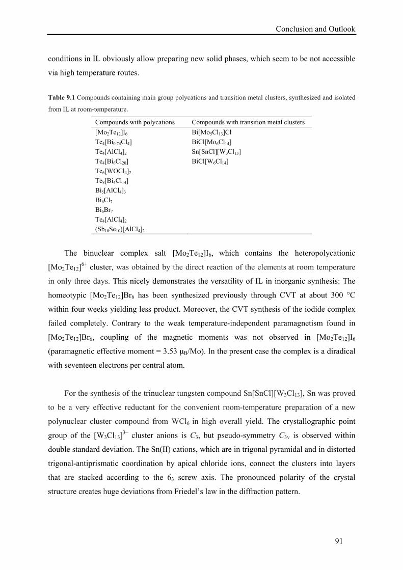
Conclusion and Outlook
91
conditions in IL obviously allow preparing new solid phases, which seem to be not accessible
via high temperature routes.
Table 9.1 Compounds containing main group polycations and transition metal clusters, synthesized and isolated
from IL at room-temperature.
Compounds with polycations Compounds with transition metal clusters
[Mo2Te12]I6 Bi[Mo5Cl13]Cl
Te4[Bi0.74Cl4] BiCl[Mo6Cl14]
Te4[AlCl4]2 Sn[SnCl][W3Cl13]
Te4[Bi6Cl20] BiCl[W6Cl14]
Te6[WOCl4]2
Te8[Bi4Cl14]
Bi5[AlCl4]3
Bi6Cl7
Bi6Br7
Te4[AlCl4]2
(Sb10Se10)[AlCl4]2
The binuclear complex salt [Mo2Te12]I6, which contains the heteropolycationic
[Mo2Te12]6+ cluster, was obtained by the direct reaction of the elements at room temperature
in only three days. This nicely demonstrates the versatility of IL in inorganic synthesis: The
homeotypic [Mo2Te12]Br6 has been synthesized previously through CVT at about 300 °C
within four weeks yielding less product. Moreover, the CVT synthesis of the iodide complex
failed completely. Contrary to the weak temperature-independent paramagnetism found in
[Mo2Te12]Br6, coupling of the magnetic moments was not observed in [Mo2Te12]I6
(paramagnetic effective moment = 3.53 μB/Mo). In the present case the complex is a diradical
with seventeen electrons per central atom.
For the synthesis of the trinuclear tungsten compound Sn[SnCl][W3Cl13], Sn was proved
to be a very effective reductant for the convenient room-temperature preparation of a new
polynuclear cluster compound from WCl6 in high overall yield. The crystallographic point
group of the [W3Cl13]3– cluster anions is C3, but pseudo-symmetry C3v is observed within
double standard deviation. The Sn(II) cations, which are in trigonal pyramidal and in distorted
trigonal-antiprismatic coordination by apical chloride ions, connect the clusters into layers
that are stacked according to the 63 screw axis. The pronounced polarity of the crystal
structure creates huge deviations from Friedel’s law in the diffraction pattern.
Conclusion and Outlook
92
The pentanuclear molybdenum cluster compound Bi[Mo5Cl13]Cl was synthesized by the
reduction of MoCl5 with elemental Bi at room temperature. The structure is a defect variant of
the Pb[Mo6Cl14] type; in statistical distribution one of the molybdenum atoms is missing in
the cluster core. With respect to the paramagnetic behavior of Bi[Mo5Cl13]Cl, a hypothetical
alternative structure model, basing on the statistical missing of each sixth complete
octahedron, is ruled out. The experimental effective magnetic moment of 1.67 μB suggests
pure spin magnetism of an unpaired electron (S = ½; g 2). In fact the [Mo5Cl13]2– anion
comprises the odd number of 19 electrons in molybdenum based cluster orbitals.
The first mixed antimony/selenium polycation (Sb10Se10)2+ was obtained by reacting Sb,
Se, and SeCl4 at room temperature. In the salt–like compound (Sb10Se10)[AlCl4]2, the
centrosymmetric polycyclic cation (Sb10Se10)2+ consists of two realgar-like [Sb4Se4] cages,
which are connected through positively charged, three-bonded selenium atoms with a central
[Sb2Se2] ring. Quantum chemical calculations predict semiconducting behavior of the
compound and indicate primarily covalent bonding with varying ionic contribution within the
[Sb10Se10]2+ polycation, while the interactions between the polycation and the [AlCl4]
– anions
are predominantly ionic.
In the modulated structure of Te4[Bi0.74Cl4], the Bi and Cl atoms chemically form a
complex sequence of chloridobismuthate(III) anions with average composition [Bi0.74Cl4]1.78–,
while the Te atoms constitute square polycations, which are stacked ecliptically parallel to the
c-axis. Along [001] isolated [BiCl6]3– and [Bi2Cl10]
4– groups form an aperiodic sequence.
Because of the modulation, in Te4[Bi0.74Cl4] each Te4-ring deviates individually from 4/mmm
symmetry. The MO diagram analysis reveals competition of intermolecular interactions with
and -bonding in the rings. In a case of nearly non-distorted square [Te4]1.78+ rings, metallic
conductivity along the one-dimensional stack is predicted by quantum chemical calculations,
which has been confirmed by the electrical conductivity experiment. In the more bismuth-rich
compound Te4[Bi0.74Cl4], a very good metallic conductivity has been observed. The low
room-temperature resistivity is comparable to iron, given that Te4[Bi0.74Cl4] is just a one-
dimensional conductor. Surprisingly, there is a transition to the superconducting state at 7.1
K, which is a very high Tc for the π-stacking. The almost negligible difference between field
cooling (fc) and zero-field cooling (zfc) susceptibilities hints at a type-I superconductor.
Conclusion and Outlook
93
The new alternative facile route has the potential to flourish and promote the richness
of the transition metals and main group cluster chemistry. The observation that different
mixtures of elements in ILs specifically generate new cluster species yield spirit for new
combinations not yet employed. Moreover, ILs offer a promising synthetic strategy towards
new chalcogenide species with cationic character rather than the more familiar anionic nature.
The different functions of the IL (as solvent or structural component) further extend the
applicability of this method and open the opportunity to create a diversity of metal complexes
and clusters with interesting structures and compositions.
These features make IL based synthetic methods convenient chemical procedures that
are versatile and general routes for the development of polycations or clusters of high
nuclearity. Finally, compared to other low-temperature synthetic routes, which make use of
cancer causing or toxic organic and inorganic substances like benzene, SO2, and AsF5, IL are
more convenient, economical and environmental friendly solvents.

Acknowledgment
94
10. Acknowledgment
I would like to express my profound gratitude to Prof. Michael Ruck for assigning me this
fascinating project, his excellent supervision, encouragement, and fruitful discussion.
Prof. Johannes Beck (Universität Bonn), Prof. Thomas Straßner (TU Dresden) and
Prof. Arnold Guloy (University of Houston, USA) are gratefully acknowledged for the
valuable discussions, suggestions, and effective cooperation.
I am deeply indebted to Dr. Thomas Doert for his technical assistance especially with regards
to crystallographic problems and Dr. Anna Isaeva for the quantum chemical calculations.
I am thankful to Christoph Ziegler and Ellen Kern (Physikalische Chemie, TU Dresden) for
performing Raman spectroscopy and EDX analysis respectively, Dr. Walter Schnelle (Max
Planck Institute for Chemical Physics of Solids, Dresden) for magnetization and electrical
conductivity experiments.
Jutta Krug and Gudrun Kadner are appreciatively acknowledged for their continuous
experimental assistance.
Ilona Salzmann is thanked for her administrative support.
I express my appreciation to all my colleagues of AK Ruck, especially Dr. Andreas Heerwig
for his constant support in solving the tricky structures and Daniel Köhler for his regular help
regarding all matters inside and outside the institute.
Finally, I would like to pay thanks to all my students for their excellent contribution in
synthesis, my family for their constant prayers, and my wife for her great care and patience.
The generous financial support from the Higher Education Commission of Pakistan (HEC),
the German Academic Exchange Service (DAAD), and the Max Planck Society (MPG) is
gratefully acknowledged.
References
95
11. References
[1] M. H. Klaproth, Phil. Mag. 1798, 1, 78–82.
[2] R. J. Gillespie, J. Passmore in: H. J. Emeleus, A. G. Sharpe (eds.), Advances in
Inorganic Chemistry and Radiochemistry, Academic Press Inc, London 1975, vol. 15,
pp. 49–88.
[3] N. J. Bjerrum, G. P. Smith, J. Am. Chem. Soc. 1968, 90, 4472–4473.
[4] a) J. Barr, R. J. Gillespie, R. Kapoor, C. Malhotra, Can. J. Chem. 1968, 49, 149–159;
b) J. Barr, R. J. Gillespie. R. Kapoor, G. P. Pez, J. Am. Chem. Soc. 1968, 90, 6855–
6856.
[5] a) N. Bartlett, D. H. Lohmann, Proc. Chem. Soc. 1962, 115–116; b) N. Bartlett, D. H.
Lohmann, J. Chem. Soc. 1962, 5253–5261.
[6] A. Hershaft, J. D. Corbett, Inorg. Chem. 1963, 2, 979–985.
[7] a) R. M. Friedman, J. D. Corbett, Inorg. Chem. 1973, 12, 1134–1139; b) R. M.
Friedman, J. D. Corbett, Inorg. Chim. Acta 1973, 7, 525–527.
[8] a) R. C. Paul, K. K. Paul, K. C. Malhotra, J. Chem. Soc. D. 1970, 453b–454; b) R. C.
Paul, J. K. Puri, K. C. Malhotra, J. Chem. Soc. D. 1971, 1031; c) R. C. Paul, J. K. Puri,
K. K. Paul, R. D. Sharma, K. C. Malhotra, Inorg. Nucl. Chem. Lett. 1971, 7, 725–728.
[9] a) P. A. W. Dean, R. J. Gillespie, J. Chem. Soc. D. 1970, 853; b) R. J. Gillespie, O. C.
Vaidya, J. Chem. Soc., Chem. Commun. 1972, 40–41.
[10] a) A. Vij, W. W. Wilson, V. Vij, F. S. Tham, J. A. Sheehy, K. O. Christe, J. Am.
Chem. Soc. 2001, 123, 6308–6313; b) M. Lindsjö, A. Fischer, L. Kloo, Angew. Chem.
2004, 116, 2594–2597; Angew. Chem. Int. Ed. 2004, 43, 2540–2543.
[11] a) R. J. Gillespie, J. Passmore, Acc. Chem. Res. 1971, 4, 413–419; b) R. J. Gillespie,
Chem. Soc. Rev. 1979, 8, 315–352.
[12] a) M. Binnewies, R. Glaum, M. Schmidt, P. Schmidt, Chemische Transportreaktionen,
de Gruyter, Berlin 2011; b) H. Schäfer, Chemische Transportreaktionen, Verlag
Chemie, Weinheim 1962.
[13] a) J. Beck, Angew. Chem. 1994, 106, 172–182; Angew. Chem. Int. Ed. Engl. 1994, 33,
163–172; b) J. Beck, Coord. Chem. Rev. 1997, 163, 55–70.
[14] a) J. D. Corbett, Inorg. Chem. 1968, 7, 198–208; b) T. W. Couch, D. A. Lokken, J. D.
Corbett, Inorg. Chem. 1972, 11, 357–362; c) J. D. Corbett, Prog. Inorg. Chem. 1976,
21, 129–158.
[15] M. Ruck, F. Steden, Z. Anorg. Allg. Chem. 2007, 633, 1556–1562.
References
96
[16] a) M. Lindsjö, L. Kloo, Acta Crystallogr. 2005, E61, i18–i19; b) A. N. Kuznetsov, B.
A. Popovkin, K. Ståhl, M. Lindsjö, L. Kloo, Eur. J. Inorg. Chem. 2005, 4907–4913; c)
M. Lindsjö, A. Fischer, L. Kloo, Eur. J. Inorg. Chem. 2005, 670–675.
[17] E. Ahmed, D. Köhler, M. Ruck, Z. Anorg. Allg. Chem. 2009, 635, 297–300.
[18] E. Ahmed, M. Groh, M. Ruck, Eur. J. Inorg. Chem. 2010, 5294–5297.
[19] E. Ahmed, E. Ahrens, M. Heise, M. Ruck, Z. Anorg. Allg. Chem. 2010, 636, 2602–
2606.
[20] a) E. Ahmed, E. Ahrens, M. Heise, M. Ruck, Z. Anorg. Allg. Chem. 2010, 636, 2053;
b) E. Ahmed, E. Ahrens, M. Heise, M. Ruck, Z. Anorg. Allg. Chem. 2011, 637, 961–
964.
[21] Q. Zhang, I. Chung, J. I. Jang, J. B. Ketterson, M. G. Kanatzidis, J. Am. Chem. Soc.
2009, 131, 9896–9897.
[22] K. Biswas, Q. Zhang, I. Chung, J. H. Song, J. Androulakis, A. J. Freeman, M. G.
Kanatzidis, J. Am. Chem. Soc. 2010, 132, 14760–14762.
[23] D. Freudenmann, C. Feldmann, Dalton Trans. 2011, 40, 452–456.
[24] N. Burford, J. Passmore, J. C. P. Sanders, in: J. F. Liebman, A. Greenberg (eds.),
From Atoms to Polymers: Isoelectronic Analogies, New York 1989, vol. 11, pp. 53–
108.
[25] S. Brownridge, I. Krossing, J. Passmore, H. D. B. Jenkins, H. K. Roobottom, Coord.
Chem. Rev. 2000, 197, 397–481.
[26] S. Ulvenlund, L. Bengtsson-Kloo in: P. Braunstein, L. A. Oro, P. R. Raithby (eds),
Metal Clusters in Chemistry, Wiley-VCH, Weinheim 1999, vol. 1, pp. 561–662.
[27] M. Ruck, Angew. Chem. 2001, 113, 1222–1234; Angew. Chem. Int. Ed. 2001, 40,
1182–1193.
[28] I. Krossing in: M. Driess, H. Nöth (eds), Molecular clusters of the main group
elements, Wiley-VCH, Weinheim 2004, pp. 209–229.
[29] W. S. Sheldrick in: M. Driess, H. Nöth (eds), Molecular clusters of the main group
elements, Wiley-VCH, Weinheim 2004, pp. 230–245.
[30] T. A. O’Donnell, Chem. Soc. Rev. 1987, 16, 1–43.
[31] I. D. Brown, D. B. Crump, R. J. Gillespie, Inorg. Chem. 1971, 10, 2319–2323.
[32] J. Passmore, G. Sutherland, P. S. White, J. Chem. Soc., Chem. Commun. 1980, 330–
331.
[33] G. Cardinal, R. J. Gillespie, J. F. Sawyer, J. E. Vekris, J. Chem. Soc., Dalton Trans.
1982, 765–779.
References
97
[34] M. J. Rothman, L. S. Bartell, C. S. Ewig, J. R. van Wazer, J. Comput. Chem. 1980, 1,
64–68.
[35] R. C. Burns, R. J. Gillespie, W. C. Luk, D. R. Slim, Inorg. Chem. 1979, 18, 3086–
3094.
[36] G. W. Drake, G. L. Schimek, J. W. Kolis, Inorg. Chem. 1996, 35, 1740–1742.
[37] C. G. Davies, R. J. Gillespie, J. J. Park, J. Passmore, Inorg. Chem. 1971, 10, 2781–
2784.
[38] M. J. Collins, R. J. Gillespie, J. F. Sawyer, Acta Crystallogr. 1988, C44, 405–409.
[39] R. K. Mcmullan, D. J. Prince, J. D. Corbett, J. Chem. Soc. D. 1969, 1438–1439.
[40] R. C. Burns, W. L. Chan, R. J. Gillespie, W. C. Luk, J. F. Sawyer, D. R. Slim, Inorg.
Chem. 1980, 19, 1432–1439.
[41] R. C. Burns, R. J. Gillespie, J. F. Sawyer, Inorg. Chem. 1980, 19, 1423–1432.
[42] R. C. Burns, R. J. Gillespie, W. C. Luk, Inorg. Chem. 1978, 17, 3596–3604.
[43] a) P. Boldrini, I. D. Brown, M. J. Collins, R. J. Gillespie, E. Maharajh, D. R. Slim, J.
F. Sawyer, Inorg. Chem. 1985, 24, 4302–4307; b) M. J. Collins, R. J. Gillespie, J. F.
Sawyer, G. J. Schrobilgen, Inorg. Chem. 1986, 25, 2053–2057.
[44] a) R. C. Burns, M. J. Collins, S. M. Eicher, R. J. Gillespie, J. F. Sawyer, Inorg. Chem.
1988, 27, 1807–1813; b) R. J. Gillespie, W. Luk, E. Maharajh, D. R. Slim, Inorg.
Chem. 1977, 16, 892–896.
[45] M. J. Collins, R. J. Gillespie, J. F. Sawyer, Inorg. Chem. 1987, 26, 1476–1481.
[46] R. Faggiani, R. J. Gillespie, J. E. Vekris, J. Chem. Soc., Chem. Commun. 1988, 902–
904.
[47] P. Boldrini, I. D. Brown, R. J. Gillespie, P. R. Ireland, W. Luk, D. R. Slim, J. E.
Vekris, Inorg. Chem. 1976, 15, 765–770.
[48] a) B. H. Christian, R. J. Gillespie, J. F. Sawyer, Inorg. Chem. 1981, 20, 3410–3420; b)
R. J. Gillespie, J. P. Kent, J. F. Sawyer, D. R. Slim, J. D. Tyrer, Inorg. Chem. 1981,
20, 3799–3812; c) A. J. Banister, P. J. Dainty, A. C. Hazell, R. G. Hazell, J. G.
Lomborg, J. Chem. Soc. D. 1969, 1187; d) A. J. Banister, H. G. Clarke, I. Rayment, H.
M. M. Shearer, Inorg. Nucl. Chem. Lett. 1974, 10, 647–654; e) C. Knapp, A. Mailman,
G. B. Nikiforov, J. Passmore, J. Fluorine Chem. 2006, 127, 916–919.
[49] a) Y. C. Leung, J. Waser, S. van Houten, A. Vos, G. A. Wiegers, E. H. Wiebenga,
Acta Crystallogr. 1957, 10, 574–582; b) R. Gleiter, M. C. Böhm, M. Eckert-Maksic,
W. Schäfer, M. Baudler, Y. Aktalay, G. Fritz, K. D. Hoppe, Chem. Ber. 1983, 116,
2972–2982.
References
98
[50] a) B. Krebs, M. Mummert, C. Brendel, J. Less-Common Met. 1986, 116, 159–168; b)
B. Krebs, M. Hucke, C. J. Brendel, Angew. Chem. 1982, 94, 453–454; Angew. Chem.
Int. Ed. 1982, 21, 445–446; c) J. Beck, C. J. Brendel, L. Bengtsson-Kloo, B. Krebs, M.
Mummert, A. Stankowski, S. Ulvenlund. Chem. Ber. 1996, 129, 1219–1226.
[51] a) M. Ruck, Z. Anorg. Allg. Chem. 2000, 626, 14–22; b) M. Ruck, V. Dubenskyy, T.
Söhnel, Angew. Chem. 2003, 115, 3086–3090; Angew. Chem. Int. Ed. 2003, 42, 2978–
2982; c) V. Dubenskyy, M. Ruck, Z. Anorg. Allg. Chem. 2004, 630, 2458–2462; d) B.
Wahl, L. Kloo, M. Ruck, Angew. Chem. 2008, 120, 3996–3999; Angew. Chem. Int.
Ed. 2008, 47, 3932–3935; e) B. Wahl, M. Erbe, A. Gerisch, L. Kloo, M. Ruck, Z.
Anorg. Allg. Chem. 2009, 635, 743–752; f) B. Wahl, M. Ruck, Z. Anorg. Allg. Chem.
2008, 634, 2267–2275.
[52] a) N. J. Bjerrum, C. R. Boston, G. P. Smith, H. L. Davis, Inorg. Nucl. Chem. Lett.
1965, 1, 141–143; b) N. J. Bjerrum, C. R. Boston, G. P. Smith, Inorg. Chem. 1967, 6,
1162–1172; c) N. J. Bjerrum, G. P. Smith, Inorg. Chem. 1967, 6, 1968–1972.
[53] a) M. Ruck, Z. Anorg. Allg. Chem. 1998, 624, 521–528; b) M. Ruck, S. Hampel,
Polyhedron 2002, 21, 651–656.
[54] S. Hampel, M. Ruck, Z. Anorg. Allg. Chem. 2006, 632, 1150–1156.
[55] a) J. Beck, T. Hilbert, Eur. J. Inorg. Chem. 2004, 2019–2026; b) A. N. Kuznetsov, B.
A. Popovkin, Z. Anorg. Allg. Chem. 2002, 628, 2179.
[56] a) A. Hershaft, J. D. Corbett, J. Chem. Phys. 1962, 36, 551–552; b) H. von Benda, A.
Simon, W. Bauhofer, Z. Anorg. Allg. Chem. 1978, 438, 53–67; c) A. N. Kuznetsov, A.
V. Shevel'kov, S. I. Troyanov, B. A. Popovkin, Russ. J. Inorg. Chem. 1996, 41, 920–
923; d) A. N. Kuznetsov, A. V. Shevel'kov, B. A. Popovkin, Russ. J. Coord. Chem.
1998, 24, 861–866; e) V. Dubenskyy, M. Ruck, Z. Anorg. Allg. Chem. 2003, 629,
375–380; f) A. N. Kuznetsov, P. I. Naumenko, B. A. Popovkin, L. Kloo, Russ. Chem.
Bull. 2003, 52, 2100–2104; g) S. Hampel, P. Schmidt, M. Ruck, Z. Anorg. Allg. Chem.
2005, 631, 272–283; h) B. Wahl, M. Ruck, Z. Anorg. Allg. Chem. 2008, 634, 2873–
2879.
[57] a) B. Wahl, M. Ruck, Z. Anorg. Allg. Chem. 2010, 636, 337–342; b) A. Gerisch, M.
Ruck, Z. Anorg. Allg. Chem. 2010, 636, 2033.
[58] J. Beck, T. Hilbert, Z. Anorg. Allg. Chem. 2000, 626, 837–844.
[59] a) J. Beck, Chem. Ber. 1995, 128, 23–27; b) J. Beck, M. Kasper, A. Stankowski,
Chem. Ber. 1997, 130, 1189–1192.
[60] A. Baumann, J. Beck, Z. Anorg. Allg. Chem. 2004, 630, 2078–2082.
References
99
[61] a) J. Beck, Angew. Chem. 1991, 103, 1149–1151; Angew. Chem. Int. Ed. Engl. 1991,
30, 1128–1130; b) J. Beck, Z. Anorg. Allg. Chem. 1993, 619, 237–242; c) J. Beck, G.
Bock, Z. Anorg. Allg. Chem. 1994, 620, 1971–1975.
[62] J. Beck, Angew. Chem. 1990, 102, 301–302; Angew. Chem. Int. Ed. Engl. 1990, 29,
293–295.
[63] J. Beck, K. Müller-Buschbaum, Z. Anorg. Allg. Chem. 1997, 623, 409–413.
[64] a) J. Beck, A. Stankowski, Z. Naturforsch. 2001, 56b, 453–457; b) J. Beck, A. Fischer,
Z. Anorg. Allg. Chem. 2002, 628, 369–372.
[65] J. Beck, G. Bock, Angew. Chem. 1995, 107, 2739–2741; Angew. Chem. Int. Ed. Engl.
1995, 34, 2559–2561.
[66] R. K. Mcmullan, D. J. Prince, J. D. Corbett, Inorg. Chem. 1971, 10, 1749–1753.
[67] J. Beck, A. Fischer, A. Stankowski, Z. Anorg. Allg. Chem. 2002, 628, 2542–2548.
[68] J. Beck, J. Wetterau, Inorg. Chem. 1995, 34, 6202–6204.
[69] H. Braunschweig, P. Cogswell, K. Schwab, Coord. Chem. Rev. 2011, 255, 101–117.
[70] a) M. Ruck, Angew. Chem. 1997, 109, 2059–2062; Angew. Chem. Int. Ed. Engl. 1997,
36, 1971–1973; b) M. Ruck, Z. Anorg. Allg. Chem. 1997, 623, 1535–1541; c) M.
Ruck, Z. Anorg. Allg. Chem. 1997, 623, 1583–1590; d) M. Ruck, Z. Anorg. Allg.
Chem. 1997, 623, 1591–1598; e) M. Ruck, R. M. Heich, Z. Anorg. Allg. Chem. 2000,
626, 2449–2456; f) A. Günther, F. Steden, M. Ruck, Z. Anorg. Allg. Chem. 2008, 634,
423–430; g) B. Wahl, L. Kloo, M. Ruck, Z. Anorg. Allg. Chem. 2009, 635, 1979–
1985; h) M. Ruck, Solid State Sci. 2001, 3, 369–376; i) R. B. King, Dalton Trans.
2003, 395–397; j) R. B. King, Inorg. Chem. 2003, 42, 8755–8761; k) B. U. Wahl, T.
Doert, T. Söhnel, M. Ruck, Z. Anorg. Allg. Chem. 2005, 631, 457–467.
[71] a) J. Beck, M. Dolg, S. Schlüter, Angew. Chem. 2001, 113, 2347–2350; Angew. Chem.
Int. Ed. 2001, 40, 2287–2290; b) J. Beck, S. Schlüter, N. Zotov, Z. Anorg. Allg. Chem.
2004, 630, 2512–2519.
[72] J. Beck, S. Schlüter, Z. Anorg. Allg. Chem. 2005, 631, 569–574.
[73] J. Beck, T. Schlörb, Phosphorus Sulfur Silicon Relat. Elem. 1997, 124, 125, 305–313.
[74] J. Beck, S. Schlüter, N. Zotov, Z. Anorg. Allg. Chem. 2005, 631, 2450–2456.
[75] S. Ulvenlund, K. Ståhl, L. Bengtsson-Kloo, Inorg. Chem. 1996, 35, 223–230.
[76] a) A. Apblett, T. Chivers, J. F. Fait, J. Chem. Soc., Chem. Commun. 1989, 1596–1598;
b) U. Thewalt, K. Berhalter, P. Müller, Acta Crystallogr. 1982, B38, 1280–1282; c) C.
Knapp, E. Lork, T. Borrmann, W.-D. Stohrer, R. Mews, Z. Anorg. Allg. Chem. 2005,
References
100
631, 1885–1892; d) J. Åkerstedt, R. Zaffaroni, L. Kloo, Dalton Trans. 2010, 39, 8132–
8134.
[77] J. Wright, Environmental Chemistry, Taylor & Francis, New York 2003, pp. 74, 208.
[78] a) P. Wasserscheid, T. Welton, Ionic Liquids in Synthesis, Wiley-VCH, Weinheim
2007; b) P. Wasserscheid, W. Keim, Angew. Chem. 2000, 112, 3926–3945; Angew.
Chem. Int Ed. 2000, 39, 3772–3789.
[79] T. P. Lodge, Science 2008, 321, 50–51.
[80] P. J. Dyson, T. J. Geldbach, Metal Catalysed Reactions in Ionic Liquids, Springer,
Heidelberg 2005.
[81] G. Clavel, J. Larionova, Y. Guari, C. Guérin, Chem. Eur. J. 2006, 12, 3798–3804; b)
H. Zhu, J. F. Huang, Z. Pan, S. Dai, Chem. Mater. 2006, 18, 4473–4477.
[82] a) A. M. Guloy, R. Ramlau, Z. Tang, W. Schnelle, M. Baitinger, Yu. Grin, Nature
2006, 443, 320–323; b) A. M. Guloy, Z. Tang, R. Ramlau, B. Böhme, M. Baitinger,
Yu. Grin, Eur. J. Inorg. Chem. 2009, 2455–2458.
[83] R. E. Morris, Angew. Chem. 2008, 120, 450–452; Angew. Chem. Int. Ed. 2008, 47,
442–444.
[84] E. Ahmed, M. Ruck, Coord. Chem. Rev. 2011, in print.
[85] T. Keilhauer, Bachelor Thesis, Dresden University of Technology, Dresden 2010.
[86] S. J. Eck, Doctoral Thesis, University of Bonn, Bonn 2010.
[87] E. Ahmed, A. Isaeva, A. Fiedler, M. Haft, M. Ruck, Chem. Eur. J. 2011, 17, 6847–
6852.
[88] a) H. T. Sun, Y. Sakka, H. Gao, Y. Miwa, M. Fujii, N. Shirahata, Z. Bai, J. G. Li, J.
Mater. Chem. 2011, 21, 4060–4063; b) H. T. Sun, Y. Sakka, M. Fujii, N. Shirahata, H.
Gao, Opt. Lett. 2011, 36, 100–102.
[89] K. R. Seddon, J. Chem. Technol. Biotechnol. 1997, 68, 351–356.
[90] W. M. Reichert, J. D. Holbrey, K. B. Vigour, T. D. Morgan, G. A. Broker, R. D.
Rogers, Chem. Commun. 2006, 4767–4779.
[91] J. D. Holbrey, K. B. Vigour, W. M. Reichert, G. A. Broker, R. D. Rogers, J. Chem.
Cryst. 2006, 36, 799–804.
[92] K. Jin, X. Huang, L. Pang, J. Li, A. Appel, S. Wherland, Chem. Commun. 2002, 2872–
2873.
[93] A. Babai, A. V. Mudring, Chem. Mater. 2005, 17, 6230–6238.
[94] a) S. Tang, A. Babai, A. V. Mudring, Angew. Chem. 2008, 120, 7743–7746; Angew.
Chem. Int. Ed. 2008, 47, 7631–7634; b) A. Babai, A. V. Mudring, Inorg. Chem. 2006,
References
101
45, 4874–4876; c) A. Getsis, S. Tang, A. V. Mudring, Eur. J. Inorg. Chem. 2010,
2172–2177.
[95] A. Babai, A. V. Mudring, J. Alloys Compd. 2006, 418, 122–127.
[96] A. Babai, A. V. Mudring, Z. Anorg. Allg. Chem. 2006, 632, 1956–1958.
[97] A. E. Visser, R. P. Swatloski, W. M. Reichert, R. Mayton, S. Sheff, A. Wierzbicki, J.
H. Davis, R. D. Rogers, Environ. Sci. Technol. 2002, 36, 2523–2529.
[98] F. Endres, M. Bukowski, R. Hempelmann, H. Natter, Angew. Chem, 2003, 115, 3550–
3552; Angew. Chem. Int. Ed. 2003, 42, 3428–3430.
[99] N. Papageorgiou, Y. Athanassov, M. Armand, P. Bonhôte, H. Pettersson, A. Azam, M.
Grätzel, J. Electrochem. Soc. 1996, 143, 3099–3108.
[100] K. Lunstroot, K. Driesen, P. Nockemann, C. Görller-Walrand, K. Binnemans, S.
Bellayer, J. L. Bideau, A. Vioux, Chem. Mater. 2006, 18, 5711–5715.
[101] P. Nockemann, B. Thijs, N. Postelmans, K. Van Hecke, L. Van Meervelt, K.
Binnemans, J. Am. Chem. Soc. 2006, 128, 13658–13659.
[102] Y. Yoshida, J. Fujii, G. Saito, T. Hiramatsu, N. Sato, J. Mater. Chem. 2006, 16, 724–
727.
[103] I. J. B. Lin , C. S. Vasam, J. Organomet. Chem. 2005, 690, 3498–3512.
[104] M. Hasan, I. V. Kozhevnikov, M. R. H. Siddiqui, A. Steiner, N. Winterton, Inorg.
Chem. 1999, 38, 5637–5641.
[105] a) R. E. D. Sesto, T. M. McCleskey, A. K. Burrell, G. A. Baker, J. D. Thompson, B. L.
Scott, J. S. Wilkes, P. Williams, Chem. Commun. 2008, 447–449; b) S. Pitula, A. V.
Mudring, Chem. Eur. J. 2010, 16, 3355–3365; c) B. Mallick, B. Balke, C. Felser, A.
V. Mudring, Angew. Chem. 2008, 120, 7747–7750; Angew. Chem. Int. Ed. 2008, 47,
7635 –7638.
[106] a) F. W. Koknat, J. A. Parsons, A. Vongvusharintra, Inorg. Chem. 1974, 13, 1699–
1702; b) Y. Park, M. G. Kanatzidis, Chem. Mater. 1991, 3, 781–783; c) J. Beck, M.
Hengstmann, Z. Anorg. Allg. Chem. 1998, 624, 433–437; d) M. Ruck, Z. Anorg. Allg.
Chem. 1995, 621, 2034–2042.
[107] R. D. Adams, J. E. Babin, M. Tasi, Angew. Chem. 1987, 99, 691–692; Angew. Chem.
Int. Ed. Engl. 1987, 26, 685–686; b) M. M. Olmstead, P. P. Power, J. Am. Chem. Soc.
1984, 106, 1495–1496.
[108] a) G. Schmid, N. Klein, L. Korste, U. Kreibig, D. Schönauer, Polyhedron 1988, 7,
605–608; b) F. W. Vergeer, P. Matousek, M. Towrie, P. J. Costa, M. J. Calhorda, F.
Hartl, Chem. Eur. J. 2004, 10, 3451–3460.
References
102
[109] a) E. J. Welch, N. R. M. Crawford, R. G. Bergman, J. R. Long, J. Am. Chem. Soc.
2003, 125, 11464–11465; b) S. Cordier, K. Kirakci, D. Méry, C. Perrin, D. Astruc,
Inorg. Chim. Acta 2006, 359, 1705–1709.
[110] a) H.-J. Meyer, Z. Anorg. Allg. Chem. 1995, 621, 921–924; b) B. Jung, G. Meyer, Z.
Anorg. Allg. Chem. 1992, 610, 15–19; c) X. Zhao, Y. G. Li, Y. H. Wang, E. B. Wang,
Transition Met Chem. 2008, 33, 323–330; d) S. Chang, Y. F. Qi, E. B Wang, Z.
Zhang, Inorg. Chim. Acta 2009, 362, 453–457.
[111] C. L. Hussey, Pure & Appl. Chem. 1988, 60, 1763–1772.
[112] C. L. Hussey, R. Quigley, K. R. Seddon, Inorg. Chem. 1995, 34, 370–377.
[113] P. A. Barnard, I. W. Sun, C. L. Hussey, Inorg. Chem. 1990, 29, 3670–3674.
[114] R. Quigley, P. A. Barnard, C. L. Hussey, K. R. Seddon, Inorg. Chem. 1992, 31, 1255–
1261.
[115] C. E. Runyan, T. Hughbanks, J. Am. Chem. Soc. 1994, 116, 7909–7910.
[116] Y. Tian, T. Hughbanks, Inorg. Chem. 1995, 34, 6250–6254.
[117] J. D. Harris, T. Hughbanks, J. Am. Chem. Soc. 1997, 119, 9449–9459.
[118] a) D. Sun, T. Hughbanks, Inorg. Chem. 1999, 38, 992–997; b) D. Sun, T. Hughbanks,
Inorg. Chem. 2000, 39, 1964–1968.
[119] J. B. Willems, H. W. Rohm, C. Geers, M. Köckerling, Inorg. Chem. 2007, 46, 6197–
6203.
[120] H. Sakamoto, Y. Watanabe, T. Saito, Inorg. Chem. 2006, 45, 4578–4579.
[121] P. J. Dyson, Transition Met Chem. 2002, 27, 353–358.
[122] a) P. J. Dyson, Coord. Chem. Rev. 2004, 248, 2443–2458; b) T. J. Geldbach, G.
Laurenczy, R. Scopelliti, P. J. Dyson, Organometallics 2006, 25, 733–742.
[123] a) P. Nockemann, B. Thijs, K. Van Hecke, L. Van Meervelt, K. Binnemans, Cryst.
Growth Des. 2008, 8, 1353–1363; b) P. Nockemann, B. Thijs, K. Lunstroot, T. N.
Parac-Vogt, C. Görller-Walrand, K. Binnemans, K. Van Hecke, L. Van Meervelt, S.
Nikitenko, J. Daniels, C. Hennig, R. Van Deun, Chem. Eur. J. 2009, 15, 1449–1461.
[124] a) P. Nockemann, R. Van Deun, B. Thijs, D. Huys, E. Vanecht, K. Van Hecke, L. Van
Meervelt, K. Binnemans, Inorg. Chem. 2010, 49, 3351–3360; b) P. Nockemann, B.
Thijs, T. N. Parac-Vogt, K. Van Hecke, L. Van Meervelt, B. Tinant, I. Hartenbach, T.
Schleid, V. T. Ngan, M. T. Nguyen, K. Binnemans, Inorg. Chem. 2008, 47, 9987–
9999.
[125] K. Binnemans, Chem. Rev. 2007, 107, 2592–2614.
References
103
[126] a) V. A. Cocalia, K. E. Gutowski, R. D. Rogers, Coord. Chem. Rev. 2006, 250, 755–
764; b) W. R. Pitner, A. E. Bradley, D. W. Rooney, D. Sanders, K. R. Seddon, R. C.
Thied, J. E. Ratter, Green Ind. Appl. Ionic Liquids. 2003, 92, 209–226; c) P. R. V.
Rao, K . A. Venkatesan, T. G. Srinivasan, Prog. Nucl. Energy. 2008, 50, 449–455.
[127] T. Kanatani, K. Matsumoto, R. Hagiwara, Eur. J. Inorg. Chem. 2010, 1049–1055.
[128] Z. Fei, D. Zhao, R Scopelliti, P. J. Dyson, Organometallics 2004, 23, 1622–1628.
[129] H. Schäfer, H. G. Schnering, Angew. Chem. 1964, 76, 833–849.
[130] A. B. Bourlinos, K. Raman, R. Herrera, Q. Zhang, L. A. Archer, E. P. Giannelis, J.
Am. Chem. Soc. 2004, 126, 15358–15359.
[131] P. G. Rickert, M. R. Antonio, M. A. Firestone, K. A. Kubatko, T. Szreder, J. F.
Wishart, M. L. Dietz, J. Phys. Chem. B. 2007, 111, 4685–4692.
[132] H. Li, Z. Hou, Y. Qiao, B. Feng, Y. Hu, X. Wang, X. Zhao, Catal. Commun. 2010, 11,
470–475.
[133] H. Li, Y. Qiao, L. Hua, Z. Hou, B. Feng, Z. Pan, Y. Hu, X. Wang, X. Zhao, Y. Yu,
ChemCatChem. 2010, 2, 1165–1170.
[134] W. Huang, W. Zhu, H. Li, H. Shi, G. Zhu, H. Liu, G. Chen, Ind. Eng. Chem. Res.
2010, 49, 8998–9003.
[135] Y. Leng, J. Wang, D. Zhu, X. Ren, H. Ge, L. Shen, Angew. Chem. 2009, 121, 174–
177; Angew. Chem. Int. Ed. 2009, 48, 168–171.
[136] A. Corma, S. Iborra, F. X. L. Xamena, R. Montón, J. J. Calvino, C. Prestipino, J. Phys.
Chem. C. 2010, 114, 8828–8836.
[137] L. Dai, S. Yu, Y. Shan, M. He, Eur. J. Inorg. Chem. 2004, 237–241.
[138] G. Brauer, Handbuch der Präparativen Anorganischen Chemie, Ferdinand Enke,
Stuttgart, 1975, p. 432.
[139] J. S. Wilkes, J. A. Levisky, R. A. Wilson, C. L. Hussey, Inorg. Chem. 1982, 21, 1263–
1264.
[140] a) X-RED32, Data Reduction Program, Version 1.01, Stoe & Cie GmbH, Darmstadt,
2001; b) SAINT v7.XXA, Bruker AXS Inc., Madison (WI, USA), v2010.9–1.
[141] a) X-SHAPE, Crystal Optimisation for Numerical Absorption Correction Program,
Version 1.06, Stoe & Cie GmbH, Darmstadt, 1999; b) APEX2 v2010.1, Bruker AXS
Inc., Madison (WI, USA), 2010.
[142] a) G. M. Sheldrick, SHELXL97, Programs for crystal structure determination, Univ.
of Göttingen, 1997; b) G. M. Sheldrick, Acta. Crystallogr. 2008, A64, 112–122.
References
104
[143] K. Brandenburg, Diamond 3.2g, Crystal and Molecular Structure Visualization,
Crystal Impact GbR, Bonn, 2010.
[144] L. Palatinus, G. Chapuis, J. Appl. Crystallogr. 2007, 40, 786–790.
[145] a) V. Petříček, M. Dušek, L. Palatinus, Jana2006, The Crystallographic Computing
System. Institute of Physics, Praha, 2006; b) V. Petříček, V. A. van der Lee, M. Evain,
Acta Crystallogr. 1995, A51, 529–535.
[146] O. Jepsen, A. Burkhardt, O. K. Andersen, The Program TB–LMTO–ASA, Version 4.7,
Max Planck Institute for Solid State Research, Stuttgart, 1999.
[147] a) U. Barth, L. Hedin, J. Phys. C 1972, 5, 1629–1642; b) J. P. Perdew, J. A. Chevary,
S. H. Vosko, K. A. Jackson, M. R. Pederson, D. J. Singh, C. Fiolhais, Phys. Rev. B.
1992, 46, 6671–6687; c) A. D. Becke, J. Chem. Phys. 1992, 97, 9173–9177.
[148] T. Williams, C. Kelley, Gnuplot 4.4: an interactive plotting program, 2010.
http://gnuplot.sourceforge.net/.
[149] C. Fonseca Guerra, O. Visser, J. G. Snijders, G. te Velde, E. J. Baerends, in Methods
and Techniques for Computational Chemistry, METECC–5, STEF, Cagliari, pp. 303–
395, 1995; Amsterdam Density Functional, Vrije Universiteit Amsterdam,
Amsterdam, 2003.
[150] a) A. D. Becke, Phys. Rev. A 1988, 38, 3098–3100; b) J. P. Perdew, Phys. Rev. B
1986, 33, 8822–8824.
[151] a) E. van Lenthe, E. J. Baerends, J. G. Snijders, J. Chem. Phys. 1993, 99, 4597–4610;
b) E. van Lenthe, The ZORA equation, Vrije Universiteit Amsterdam, Amsterdam,
1996.
[152] a) M. Kohout, Faraday Discuss. 2007, 135, 43–54; b) M. Kohout, Int. J. Quantum
Chem. 2004, 97, 651–658.
[153] M. Kohout, DGrid 4.6, Radebeul, 2009.
[154] R. F. W. Bader, Atoms in Molecules, Oxford University Press, Oxford 1990.
[155] Sandia National Labs, Kitware Inc, Los Alamos National Labs, Paraview: Parallel
visualization application. http://paraview.org, 2008.
[156] a) I. Veremchuk, T. Mori, Yu. Prots, W. Schnelle, A. Leithe-Jasper, M. Kohout, Yu.
Grin, J. Solid State Chem. 2008, 181, 1983–1991; b) B. Silvi, A. Savin, F. R. Wagner
in: B. Silvi, P. D'Arco (eds.), Modelling of Minerals and Silicated Materials, Kluwer
Academic, New York 1997, pp. 179–199; c) S. Raub, G. Jansen, Theor. Chem. Acc.
2001, 106, 223–232.
[157] J. Beck, J. Solid State. Chem. 1996, 125, 165–170.
References
105
[158] J. Beck, private communication.
[159] V. Kolesnichenko, J. J. Luci, D. C. Swenson, L. Messerle, J. Am. Chem. Soc. 1998,
120, 13260–13261.
[160] M. Weisser, S. Tragl, H.-J. Meyer, Z. Anorg. Allg. Chem. 2006, 632, 1885–1889.
[161] J. M. Bijvoet, Nature 1954, 173, 888–891.
[162] a) H. G. von Schnering, H. G. Wöhrle, H. Schäfer, Naturwissenschaften 1961, 48,
159; b) M. Ströbele, J. Glaser, A. Lachgar, H.-J. Meyer, Z. Anorg. Allg. Chem. 2001,
627, 2002–2004; c) T. Duraisamy, A. Lachgar, Inorg. Chem. 2003, 42, 7747–7751; d)
J. R. Kennedy, P. Adler, R. Dronskowski, A. Simon, Inorg. Chem. 1996, 35, 2276–
2282.
[163] H. V. R. Dias, W. Jin, Inorg. Chem. 1996, 35, 6546–6551.
[164] N. E. Brese, M. O’Keeffe, Acta Crystallogr. 1991, B47, 192–197.
[165] K. Jödden, H. G. Schnering, H. Schäfer, Angew. Chem. 1975, 87, 594–595; Angew.
Chem. Int. Ed. 1975, 14, 570–571.
[166] K. Jödden, H. Schäfer, Z. Anorg. Allg. Chem. 1977, 430, 5–22.
[167] T. C. Zietlow, H. B. Gray, Inorg. Chem. 1986, 25, 631–634.
[168] S. Böschen, H.-L. Keller, Z. Kristallogr. 1992, 200, 305–315.
[169] J. D. Franolic, J. R. Long, R. H. Holm, J. Am. Chem. Soc. 1995, 117, 8139–8153.
[170] M. Ströbele, H.-J. Meyer, Z. Anorg. Allg. Chem. 2010, 636, 62–66.
[171] J. Beck, S. Benz, Z. Anorg. Allg. Chem. 2010, 636, 928–935.
[172] R. Blachnik, B. Jaschinski, H. Reuter, G. Kastner, Z. Kristallogr. 1997, 212, 874–877.
[173] H. Meissner, D. V. Koroľkov Z. Anorg. Allg. Chem. 1983, 496, 175–185.
[174] a) B. D. Sharma, D. J. Donohue, Acta Crystallogr. 1963, 16, 891–897; b) T. Ito, N.
Morimoto, R. Sadanaga, Acta Crystallogr. 1952, 5, 775–782; c) E. J. Porter, G. M.
Sheldrick, J. Chem. Soc., Dalton Trans. 1972, 1347–1349; d) P. Goldstein, A. Paton,
Acta Crystallogr. 1974, B30, 915–920.
[175] L. Balázs, H. J. Breunig, Coord. Chem. Rev. 2004, 248, 603–621.
[176] a) G. Cordier, R. Cook, H. Schäfer, Angew. Chem. 1980, 92, 310; Angew. Chem. Int.
Ed. Engl. 1980, 19, 324–325.
[177] a) G. Herzberg, Molecular Spectra and Molecular Structure II.Infrared and Raman
spectra of polyatomic molecules, D. Van Nostrand Company, Princeton, 1959; b) G.
L. Carlson, Spectrochim. Acta 1963, 19, 1291–1307.
[178] E. Mooser, W. B. Pearson, Phys. Rev. 1956, 101, 1608–1609.
References
106
[179] a) G. C. Rodrigues, P. Indelicato, J. P. Santos, P. Patte, F. Parente, At. Data Nucl. Data
Tab. 2004, 86, 117–233; b) F. J. Gálvez, E. Buendia, P. Maldonado, A. J. Sarsa, Eur.
Phys. J. D 2008, 46-49, 229–235.
[180] N. W. Tideswell, F. H. Kruse, J. D. Mccullough, Acta Crystallogr. 1957, 10, 99–102.
[181] A. Bondi, J. Phys. Chem. 1964, 68, 441–451.
[182] S. Schlüter, Doctoral Thesis, University of Bonn, Bonn 2004.
[183] F. R. Wagner, M. Kohout, Yu. Grin. J. Phys. Chem. A. 2008, 112, 9814–9828.
[184] A. Günther, M. Heise, F. R. Wagner, M. Ruck, Angew. Chem. 2011, in print.
[185] M. J. Cohen, L. B. Coleman, A. F. Garito, A. J. Heeger, Phys. Rev. B. 1974, 10, 1298–
1307.
Publications
107
12. Publications
This thesis is based on the following publications:
Journal Publications:
1) ‘‘Chemistry of Polynuclear Transition Metal Complexes in Ionic Liquids’’
E. Ahmed, M. Ruck, Dalton Trans. 2011, 40, 9347–9357.
2) ‘‘Homo- and Heteroatomic Polycations of Groups 15 and 16. Recent Advances in
Synthesis and Isolation Using Room Temperature Ionic Liquids’’
E. Ahmed, M. Ruck, Coord. Chem. Rev. 2011, 255, 2892–2903.
3) ‘‘[Sb10Se10]2+, a Heteronuclear Polycyclic Polycation from a Room Temperature Ionic
Liquid’’
E. Ahmed, A. Isaeva, A. Fiedler, M. Haft, M. Ruck, Chem. Eur. J. 2011, 17, 6847–6852.
4) ‘‘An Ionic Liquid Based Single Step Room Temperature Route for the Synthesis of
Molybdenum Cluster Compounds’’
E. Ahmed, E. Ahrens, M. Heise, M. Ruck, Z. Anorg. Allg. Chem. 2011, 637, 961–964.
5) ‘‘Room-Temperature Synthesis of the Highly Polar Cluster Compound
Sn[SnCl][W3Cl13]’’
E. Ahmed, M. Groh, M. Ruck, Eur. J. Inorg. Chem. 2010, 5294–5297.
6) ‘‘A Facile Route for the Synthesis of Polycationic Tellurium Cluster Compounds:
Synthesis in Ionic Liquid Media and Characterization by Single-Crystal X-Ray
Crystallography and Magnetic Susceptibility’’
E. Ahmed, E. Ahrens, M. Heise, M. Ruck, Z. Anorg. Allg. Chem. 2010, 636, 2602–2606.
7) ‘‘Raumtemperatursynthese von BiCl[Mo5Cl13] in Ionischer Flüssigkeit’’.
E. Ahmed, E. Ahrens, M. Heise, M. Ruck, Z. Anorg. Allg. Chem. 2010, 636, 2053.
8) ‘‘Room-Temperature Synthesis of Bismuth Clusters in Ionic Liquid and Crystal Growth
of Bi5(AlCl4)3’’
E. Ahmed, D. Köhler, M. Ruck, Z. Anorg. Allg. Chem. 2009, 635, 297–300.
Conference Publications:
1) ‘‘Synthesis of Inorganic Materials using Room Temperature Ionic Liquids: a Green
Chemistry Approach’’ (oral presentation).
Publications
108
E. Ahmed, M. Ruck, Book of Abstracts, 9th Green Chemistry Conference. 14-16
September, 2011 Madrid, Spain.
2) ‘‘Raumtemperatursynthese von BiCl[Mo5Cl13] in Ionischer Flüssigkeit’’ (poster
presentation).
E. Ahmed, E. Ahrens, M. Heise, M. Ruck, Book of Abstracts, 15th Conference on Solid
State Chemistry and Material Research. 20-22 September, 2010 Berlin, Germany.
3) ‘‘Low-Temperature Synthesis of Inorganic Materials from Ionic Liquids: Soft and
Sustainable Chemistry’’ (oral presentation).
E. Ahmed, M. Ruck, Book of Abstracts, 3rd European Chemistry Congress. 29 Aug-02
September, 2010 Nürnberg, Germany.
4) ‘‘Synthesis of Bismuth and Tellurium Sub-valent Cluster Compounds at Room-
Temperature’’ (poster presentation).
E. Ahmed, D. Köhler, M. Ruck, Book of Abstracts, 6th International Conference on
Inorganic Materials. 28-30 September, 2008 Dresden, Germany.
5) ‘‘Synthesis and Characterization of Main Group Sub-valent Cluster Compounds’’ (oral
presentation)
E. Ahmed, D. Köhler, M. Ruck, Book of Abstracts, 6. Mitteldeutsches Anorganiker-
Nachwuchs-Symposium. 22 September, 2008 Freiberg, Germany.
109
Versicherung
Hiermit versichere ich, dass ich die vorliegende Arbeit ohne unzulässige Hilfe Dritter und
ohne Benutzung anderer als der angegebenen Hilfsmittel angefertigt habe; die aus fremden
Quellen direkt oder indirekt übernommenen Gedanken sind als solche kenntlich gemacht. Die
Arbeit wurde bisher weder im Inland noch im Ausland in gleicher oder ähnlicher Form einer
anderen Prüfungsbehörde vorgelegt.
Die vorliegende Arbeit wurde am Institut für Anorganische Chemie der Technischen
Universität Dresden unter wissenschaftlicher Betreuung von Herrn Prof. Dr. Michael Ruck im
Zeitraum von April 2007 bis Juni 2011 angefertigt.
Es haben keine früheren erfolglosen Promotionsverfahren stattgefunden. Hiermit erkenne ich
die Promotionsordnung der Fakultät Mathematik und Naturwissenschaften der Technischen
Universität Dresden vom 23.02.2011 an.
Dresden, den 22. Jun 2011 Ejaz Ahmed
110
Curriculum Vitae Ejaz Ahmed a Department of Chemistry and Food Chemistry
Dresden University of Technology Dresden, Germany b Max-Planck Institute for Chemical Physics of Solids Dresden, Germany
Tel: +49 351-46333649
Personal Data Name Ejaz Ahmed
Date of Birth 06/07/1978
Email [email protected] Nationality Pakistani
Religion Islam
Current Address Budapester Strasse 39, 01069 Dresden, Germany
Education
2007 - 2011 PhD (Inorganic Chemistry) Dresden University of Technology Dresden, Germany
2004 - 2006 M.Phil (Analytical chemistry/Inorganic Chemistry) Quaid-i-Azam University Islamabad, Pakistan
2002 - 2004 M.Sc (Analytical Chemistry/Inorganic Chemistry) Quaid-i-Azam University Islamabad, Pakistan
Work Experience
2007 – 2011 Research Assistant Chair of Inorganic Chemistry II Dresden University of Technology, Germany
2004 - 2006 Research Assistant Department of Inorganic and analytical Chemistry Quaid-i-Azam University Islamabad, Pakistan
2004 - 2006 Lecturer Shah Institute of Sciences Rawalpindi, Pakistan