Room controller for VAV systems RXC32.1 / RXC32 Siemens RXC32 – Room controller for VAV systems...
14
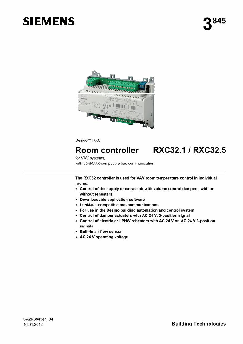
CA2N3845en_04 16.01.2012 Building Technologies 3 845 Desigo™ RXC Room controller RXC32.1 / RXC32.5 for VAV systems, with LONMARK-compatible bus communication The RXC32 controller is used for VAV room temperature control in individual rooms. • Control of the supply or extract air with volume control dampers, with or without reheaters • Downloadable application software • LONMARK-compatible bus communications • For use in the Desigo building automation and control system • Control of damper actuators with AC 24 V, 3-position signal • Control of electric or LPHW reheaters with AC 24 V or AC 24 V 3-position signals • Built-in air flow sensor • AC 24 V operating voltage
Transcript of Room controller for VAV systems RXC32.1 / RXC32 Siemens RXC32 – Room controller for VAV systems...
CA2N3845en_04 16.01.2012 Building Technologies
3845
Desigo™ RXC
Room controller RXC32.1 / RXC32.5 for VAV systems,
with LONMARK-compatible bus communication
The RXC32 controller is used for VAV room temperature control in individual rooms. • Control of the supply or extract air with volume control dampers, with or
without reheaters • Downloadable application software • LONMARK-compatible bus communications • For use in the Desigo building automation and control system • Control of damper actuators with AC 24 V, 3-position signal • Control of electric or LPHW reheaters with AC 24 V or AC 24 V 3-position
signals • Built-in air flow sensor • AC 24 V operating voltage
2/14
Siemens RXC32 – Room controller for VAV systems CA2N3845en_04 Building Technologies 16.01.2012
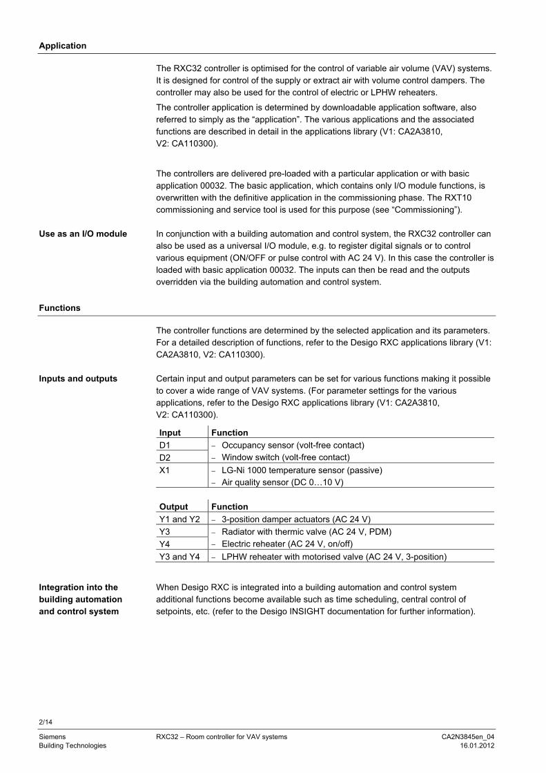
Application
The RXC32 controller is optimised for the control of variable air volume (VAV) systems. It is designed for control of the supply or extract air with volume control dampers. The controller may also be used for the control of electric or LPHW reheaters.
The controller application is determined by downloadable application software, also referred to simply as the “application”. The various applications and the associated functions are described in detail in the applications library (V1: CA2A3810, V2: CA110300).
The controllers are delivered pre-loaded with a particular application or with basic application 00032. The basic application, which contains only I/O module functions, is overwritten with the definitive application in the commissioning phase. The RXT10 commissioning and service tool is used for this purpose (see “Commissioning”).
In conjunction with a building automation and control system, the RXC32 controller can also be used as a universal I/O module, e.g. to register digital signals or to control various equipment (ON/OFF or pulse control with AC 24 V). In this case the controller is loaded with basic application 00032. The inputs can then be read and the outputs overridden via the building automation and control system.
Functions
The controller functions are determined by the selected application and its parameters. For a detailed description of functions, refer to the Desigo RXC applications library (V1: CA2A3810, V2: CA110300). Certain input and output parameters can be set for various functions making it possible to cover a wide range of VAV systems. (For parameter settings for the various applications, refer to the Desigo RXC applications library (V1: CA2A3810, V2: CA110300).
Input Function
D1
D2
− Occupancy sensor (volt-free contact) − Window switch (volt-free contact)
X1 − LG-Ni 1000 temperature sensor (passive) − Air quality sensor (DC 0…10 V)
Output Function
Y1 and Y2 − 3-position damper actuators (AC 24 V)
Y3
Y4
− Radiator with thermic valve (AC 24 V, PDM) − Electric reheater (AC 24 V, on/off)
Y3 and Y4 − LPHW reheater with motorised valve (AC 24 V, 3-position)
When Desigo RXC is integrated into a building automation and control system additional functions become available such as time scheduling, central control of setpoints, etc. (refer to the Desigo INSIGHT documentation for further information).
Use as an I/O module
Inputs and outputs
Integration into the building automation and control system
3/14
Siemens RXC32 – Room controller for VAV systems CA2N3845en_04 Building Technologies 16.01.2012
Types
Type SSN Description
RXC32.1 RXC32.5
S55373-C116
Room controller for VAV systems
RXZ30.1 Accessory: Terminal covers
Ordering
When ordering please specify the quantity, product name and type code. The controllers will be delivered with basic application 00032.
The RXZ30.1 terminal covers are supplied in packs of 1 pair and must be ordered separately).
Example: 30 Room controllers for VAV systems RXC32.5/00032 30 Pairs of terminal covers RXZ30.1
Compatibility
For operation of the RXC32 room controller, a room unit from the QAX… series may be used in conjunction with conventional momentary contact switches for lighting and blind control. Alternatively, the flexible room units, QAX50.1 or QAX51.1 may be used.
See the RX hardware overview (CA2N3804) for a summary of the available field devices.
Mechanical design
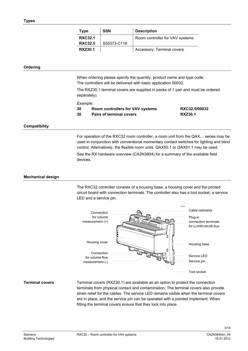
The RXC32 controller consists of a housing base, a housing cover and the printed circuit board with connection terminals. The controller also has a tool socket, a service LED and a service pin.
Connection for volume
measurement (+)
Housing cover
Connection for volume flow
measurement (-)
90130
Cable restraints
Plug-in connection terminals for LONWORKS® bus
Housing base
Service LED
Service pin
Tool socket
Terminal covers (RXZ30.1) are available as an option to protect the connection terminals from physical contact and contamination. The terminal covers also provide strain relief for the cables. The service LED remains visible when the terminal covers are in place, and the service pin can be operated with a pointed implement. When fitting the terminal covers ensure that they lock into place.
Terminal covers
4/14
Siemens RXC32 – Room controller for VAV systems CA2N3845en_04 Building Technologies 16.01.2012
80049
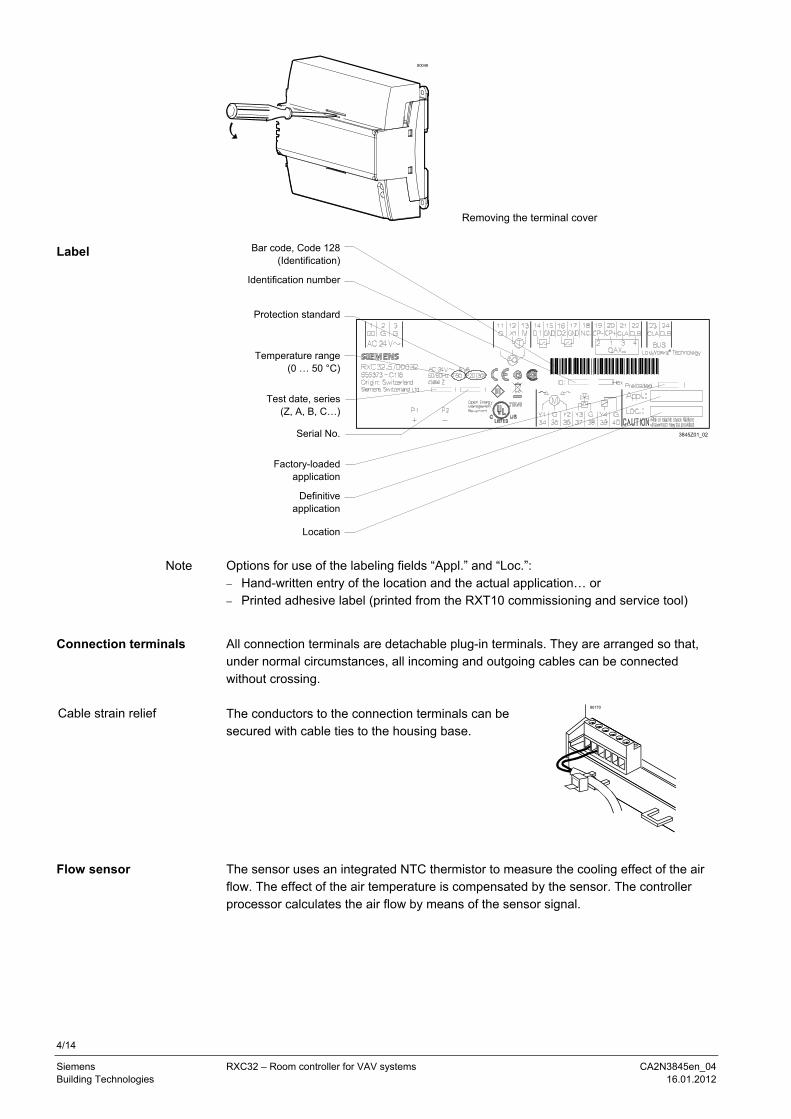
Removing the terminal cover
Bar code, Code 128
(Identification)
Identification number
Protection standard
Temperature range(0 … 50 °C)
Test date, series(Z, A, B, C…)
Serial No.
Factory-loadedapplication
Definitive application
Location Options for use of the labeling fields “Appl.” and “Loc.”: − Hand-written entry of the location and the actual application… or − Printed adhesive label (printed from the RXT10 commissioning and service tool)
All connection terminals are detachable plug-in terminals. They are arranged so that, under normal circumstances, all incoming and outgoing cables can be connected without crossing. The conductors to the connection terminals can be secured with cable ties to the housing base.
80170
The sensor uses an integrated NTC thermistor to measure the cooling effect of the air flow. The effect of the air temperature is compensated by the sensor. The controller processor calculates the air flow by means of the sensor signal.
Label
Note
Connection terminals
Cable strain relief
Flow sensor
5/14
Siemens RXC32 – Room controller for VAV systems CA2N3845en_04 Building Technologies 16.01.2012
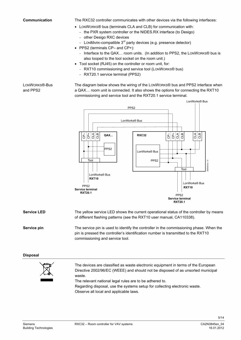
The RXC32 controller communicates with other devices via the following interfaces:
• LONWORKS® bus (terminals CLA and CLB) for communication with: − the PXR system controller or the NIDES.RX interface (to Desigo) − other Desigo RXC devices − LONMARK-compatible 3rd party devices (e.g. presence detector)
• PPS2 (terminals CP– and CP+): − Interface to the QAX… room units. (In addition to PPS2, the LONWORKS® bus is
also looped to the tool socket on the room unit.) • Tool socket (RJ45) on the controller or room unit, for:
− RXT10 commissioning and service tool (LONWORKS® bus) − RXT20.1 service terminal (PPS2)
The diagram below shows the wiring of the LONWORKS® bus and PPS2 interface when a QAX… room unit is connected. It also shows the options for connecting the RXT10 commissioning and service tool and the RXT20.1 service terminal.
The yellow service LED shows the current operational status of the controller by means of different flashing patterns (see the RXT10 user manual, CA110338). The service pin is used to identify the controller in the commissioning phase. When the pin is pressed the controller’s identification number is transmitted to the RXT10 commissioning and service tool.
Disposal
The devices are classified as waste electronic equipment in terms of the European Directive 2002/96/EC (WEEE) and should not be disposed of as unsorted municipal waste. The relevant national legal rules are to be adhered to. Regarding disposal, use the systems setup for collecting electronic waste. Observe all local and applicable laws.
Communication
LONWORKS®-Bus and PPS2
Service LED
Service pin
6/14
Siemens RXC32 – Room controller for VAV systems CA2N3845en_04 Building Technologies 16.01.2012
Engineering notes
The Desigo RXC installation guide, document CA110334, contains the relevant engineering information for the LONWORKS® bus (topology, bus repeaters, bus termination, etc.) and for the selection and dimensions of connecting cables for the supply voltage and field devices. See “Connection diagrams” for information on connecting field devices.
The controller operates with an AC 24 V supply voltage (SELV / PELV). The supply cable must be protected with at least 10 A. The controlled devices (valves and damper actuators) are supplied directly from the controller. The maximum load on the outputs must not be exceeded (see “Technical data”). The power consumption of the connected devices must be taken into account when sizing the transformer.
• The simultaneous load on outputs Y3… Y6 must not exceed 24 VA. • The maximum load on each output must not exceed 12 VA. Equipment Y1, Y2 1 3-position motorised actuator GDB…1E 2 VA Y3 (Cooling) 2 thermic valve actuators, type STP72E 6 W Y4 (Heating) 2 thermic valve actuators, type STP72E 6 W Simultaneous load: 2 motorised actuators (both ON continuously) 4 VA 2 thermic valve actuators * 6 W (12 W) ** 10 W (16 W) * The heating and cooling sequences are never operative simultaneously. Therefore,
only the actuators for one of the two sequences need to be included when calculating the total load.
** When cold, thermic valve actuators have a consumption of approximately 6 W. A maximum of two thermic actuators may be connected to any one Y... output.
Mounting
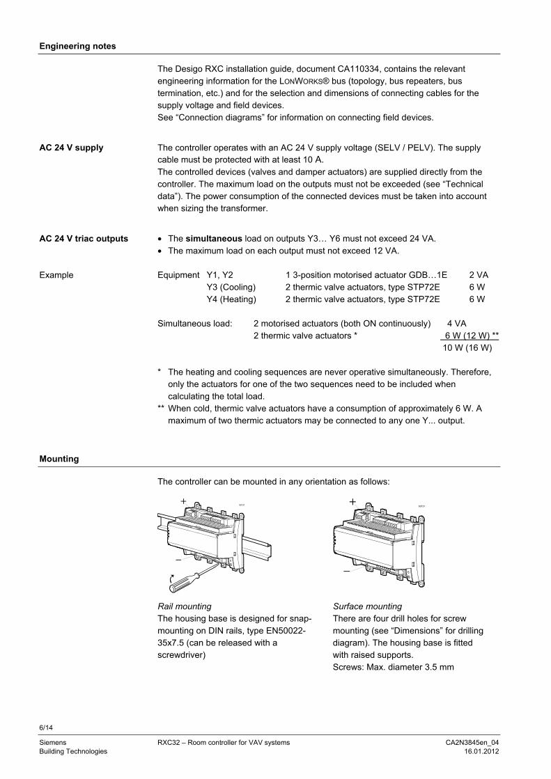
The controller can be mounted in any orientation as follows:
90131
90131
Rail mounting The housing base is designed for snap-mounting on DIN rails, type EN50022-35x7.5 (can be released with a screwdriver)
Surface mounting There are four drill holes for screw mounting (see “Dimensions” for drilling diagram). The housing base is fitted with raised supports. Screws: Max. diameter 3.5 mm
AC 24 V supply
AC 24 V triac outputs
Example
7/14
Siemens RXC32 – Room controller for VAV systems CA2N3845en_04 Building Technologies 16.01.2012
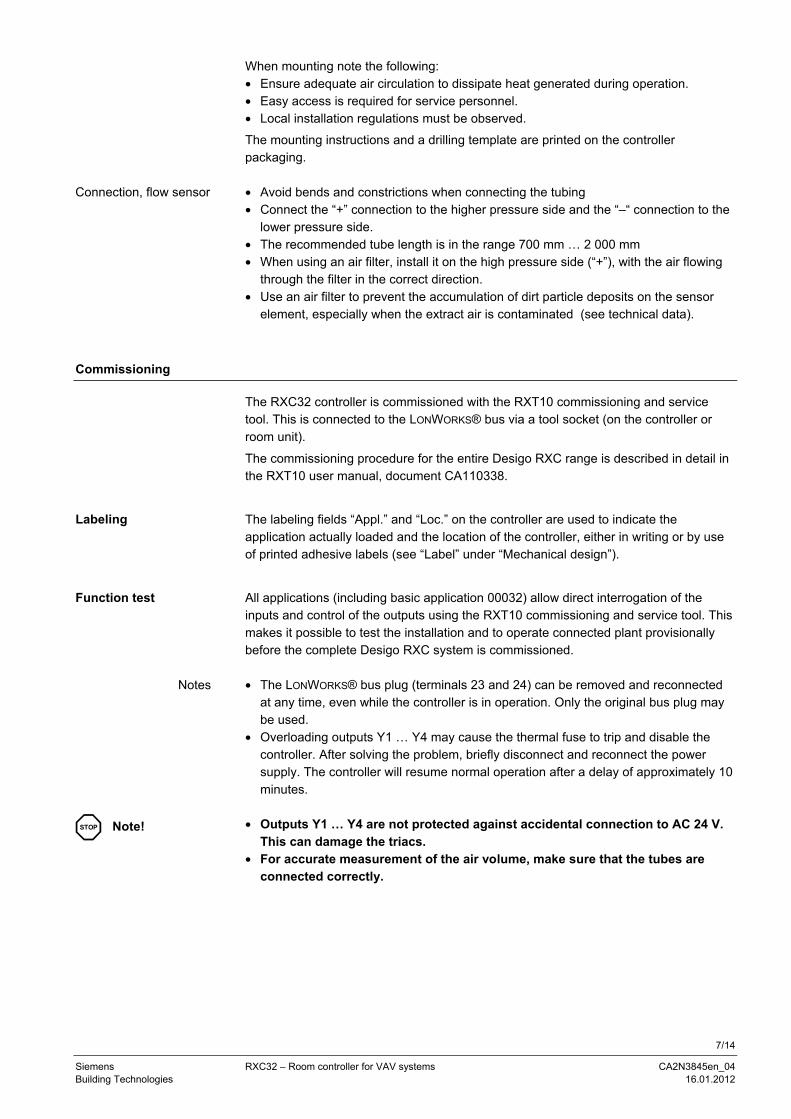
When mounting note the following: • Ensure adequate air circulation to dissipate heat generated during operation. • Easy access is required for service personnel. • Local installation regulations must be observed.
The mounting instructions and a drilling template are printed on the controller packaging. • Avoid bends and constrictions when connecting the tubing • Connect the “+” connection to the higher pressure side and the “–“ connection to the
lower pressure side. • The recommended tube length is in the range 700 mm … 2 000 mm • When using an air filter, install it on the high pressure side (“+”), with the air flowing
through the filter in the correct direction. • Use an air filter to prevent the accumulation of dirt particle deposits on the sensor
element, especially when the extract air is contaminated (see technical data).
Commissioning
The RXC32 controller is commissioned with the RXT10 commissioning and service tool. This is connected to the LONWORKS® bus via a tool socket (on the controller or room unit).
The commissioning procedure for the entire Desigo RXC range is described in detail in the RXT10 user manual, document CA110338.
The labeling fields “Appl.” and “Loc.” on the controller are used to indicate the application actually loaded and the location of the controller, either in writing or by use of printed adhesive labels (see “Label” under “Mechanical design”).
All applications (including basic application 00032) allow direct interrogation of the inputs and control of the outputs using the RXT10 commissioning and service tool. This makes it possible to test the installation and to operate connected plant provisionally before the complete Desigo RXC system is commissioned. • The LONWORKS® bus plug (terminals 23 and 24) can be removed and reconnected
at any time, even while the controller is in operation. Only the original bus plug may be used.
• Overloading outputs Y1 … Y4 may cause the thermal fuse to trip and disable the controller. After solving the problem, briefly disconnect and reconnect the power supply. The controller will resume normal operation after a delay of approximately 10 minutes.
• Outputs Y1 … Y4 are not protected against accidental connection to AC 24 V.
This can damage the triacs. • For accurate measurement of the air volume, make sure that the tubes are
connected correctly.
Connection, flow sensor
Labeling
Function test
Notes
STOP Note!
8/14
Siemens RXC32 – Room controller for VAV systems CA2N3845en_04 Building Technologies 16.01.2012
Technical data
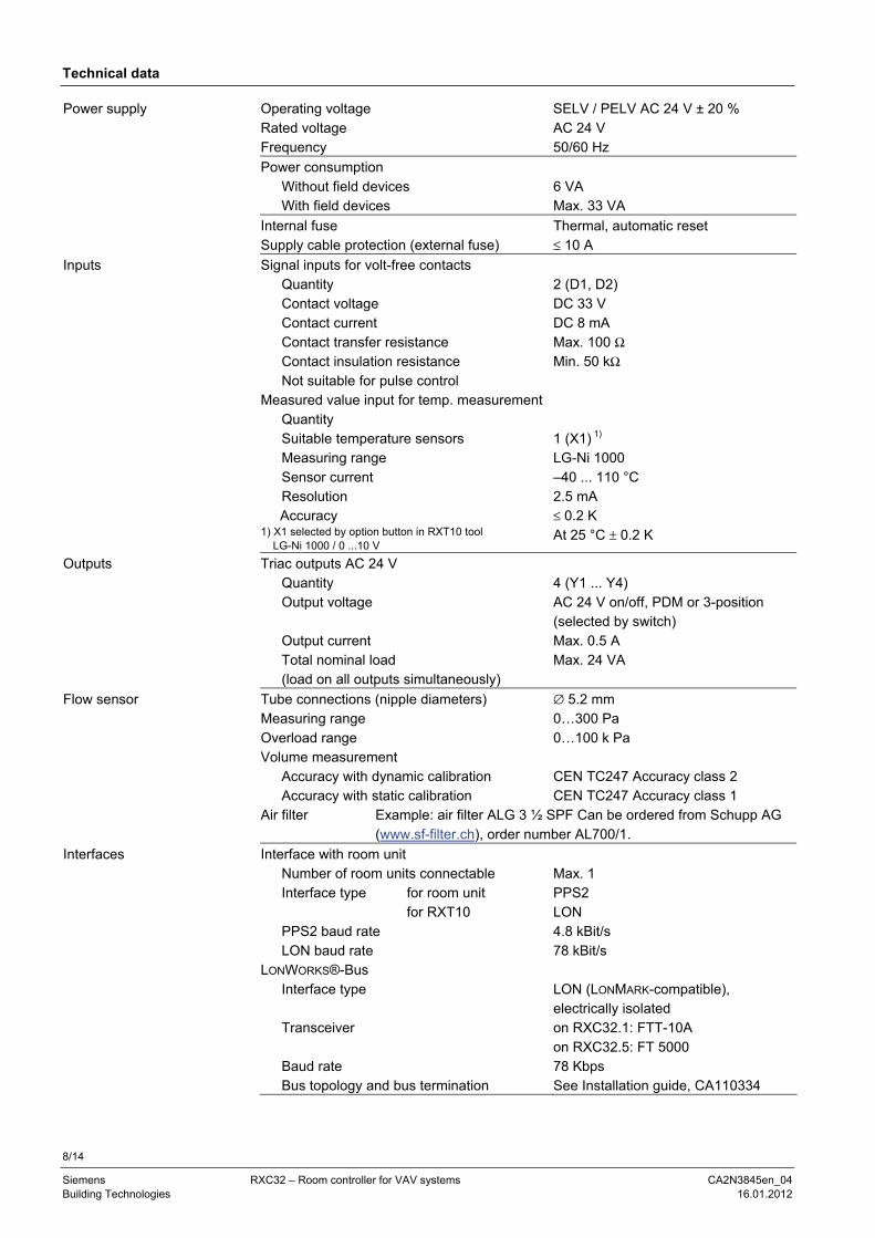
Power supply Operating voltage SELV / PELV AC 24 V ± 20 % Rated voltage AC 24 V Frequency 50/60 Hz
Power consumption Without field devices With field devices
6 VA Max. 33 VA
Internal fuse Thermal, automatic reset Supply cable protection (external fuse) ≤ 10 A
Inputs Signal inputs for volt-free contacts Quantity Contact voltage Contact current Contact transfer resistance Contact insulation resistance Not suitable for pulse control
2 (D1, D2) DC 33 V DC 8 mA Max. 100 Ω Min. 50 kΩ
Measured value input for temp. measurementQuantity Suitable temperature sensors Measuring range Sensor current Resolution
Accuracy 1) X1 selected by option button in RXT10 tool LG-Ni 1000 / 0 ...10 V
1 (X1) 1) LG-Ni 1000 –40 ... 110 °C 2.5 mA ≤ 0.2 K At 25 °C ± 0.2 K
Outputs Triac outputs AC 24 V Quantity Output voltage Output current Total nominal load (load on all outputs simultaneously)
4 (Y1 ... Y4) AC 24 V on/off, PDM or 3-position (selected by switch) Max. 0.5 A Max. 24 VA
Flow sensor
Tube connections (nipple diameters) Measuring range Overload range Volume measurement
Accuracy with dynamic calibration Accuracy with static calibration
∅ 5.2 mm 0…300 Pa 0…100 k Pa CEN TC247 Accuracy class 2 CEN TC247 Accuracy class 1
Air filter Example: air filter ALG 3 ½ SPF Can be ordered from Schupp AG (www.sf-filter.ch), order number AL700/1.
Interfaces Interface with room unit Number of room units connectable Interface type for room unit for RXT10 PPS2 baud rate LON baud rate
Max. 1 PPS2 LON 4.8 kBit/s 78 kBit/s
LONWORKS®-Bus Interface type Transceiver Baud rate Bus topology and bus termination
LON (LONMARK-compatible), electrically isolated on RXC32.1: FTT-10A on RXC32.5: FT 5000 78 Kbps See Installation guide, CA110334
9/14
Siemens RXC32 – Room controller for VAV systems CA2N3845en_04 Building Technologies 16.01.2012
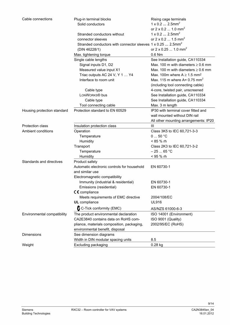
Cable connections Plug-in terminal blocks Solid conductors Stranded conductors without connector sleeves Stranded conductors with connector sleeves (DIN 46228/1)
Rising cage terminals 1 x 0.2 ... 2.5mm2 or 2 x 0.2 ... 1.0 mm2 1 x 0.2 ... 2.5mm2 or 2 x 0.2 ... 1.5 mm2 1 x 0.25 ... 2.5mm2 or 2 x 0.25 ... 1.0 mm2
Max. tightening torque 0.6 Nm Single cable lengths
Signal inputs D1, D2 Measured value input X1 Triac outputs AC 24 V, Y 1 … Y4 Interface to room unit Cable type LONWORKS® bus Cable type Tool connecting cable
See Installation guide, CA110334 Max. 100 m with diameters ≥ 0.6 mm Max. 100 m with diameters ≥ 0.6 mm Max. 100m where A ≥ 1.5 mm2 Max. 115 m where A= 0.75 mm2 (including tool connecting cable) 4-core, twisted pair, unscreened See Installation guide, CA110334 See Installation guide, CA110334 Max. 3 m length
Housing protection standard Protection standard to EN 60529 IP30 with terminal cover fitted and wall mounted without DIN rail All other mounting arrangements: IP20
Protection class Insulation protection class III
Ambient conditions Operation Temperature Humidity
Class 3K5 to IEC 60,721-3-3 0 ... 50 °C < 85 % rh
Transport Temperature Humidity
Class 2K3 to IEC 60,721-3-2 – 25 ... 65 °C < 95 % rh
Standards and directives Product safety Automatic electronic controls for household and similar use
EN 60730-1
Electromagnetic compatibility Immunity (industrial & residential) EN 60730-1 Emissions (residential) EN 60730-1 compliance Meets requirements of EMC directive 2004/108/EC UL compliance UL916 C-Tick conformity (EMC) AS/NZS 61000-6-3
Environmental compatibility The product environmental declaration CA2E3840 contains data on RoHS com-pliance, materials composition, packaging, environmental benefit, disposal
ISO 14001 (Environment) ISO 9001 (Quality) 2002/95/EC (RoHS)
Dimensions See dimension diagrams Width in DIN modular spacing units 8.5
Weight Excluding packaging 0.28 kg
10/14
Siemens RXC32 – Room controller for VAV systems CA2N3845en_04 Building Technologies 16.01.2012
Connection terminals
M
3845
A02
_01
1 2 3 11 12 13 14 15 23 24
G0
G G X1
M D1
GN
D
CL
A
CL
B
LonWorks®
Bus12 3 4
QAX...
G
34
Y1
40
G
39
Y4
3837
Y3
36
Y2
G
35
G
16 17 18 19 20 21
CP
–
CP
+
CLA
CLB
GN
D
22
T
D2
AC
24
V
+ P
1
– P
2
N.C
.
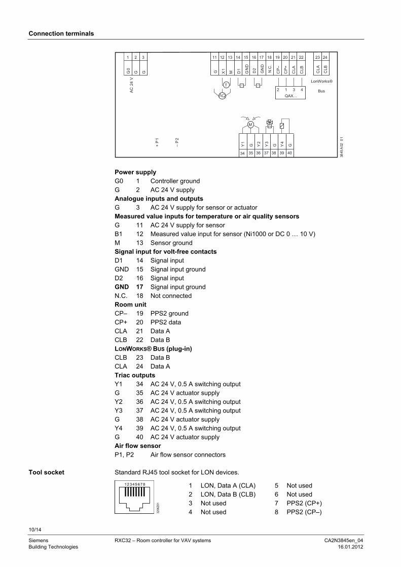
Power supply G0 1 Controller ground G 2 AC 24 V supply Analogue inputs and outputs G 3 AC 24 V supply for sensor or actuator Measured value inputs for temperature or air quality sensors G 11 AC 24 V supply for sensor B1 12 Measured value input for sensor (Ni1000 or DC 0 … 10 V) M 13 Sensor ground Signal input for volt-free contacts D1 14 Signal input GND 15 Signal input ground D2 16 Signal input GND 17 Signal input ground N.C. 18 Not connected Room unit CP– 19 PPS2 ground CP+ 20 PPS2 data CLA 21 Data A CLB 22 Data B LONWORKS® BUS (plug-in) CLB 23 Data B CLA 24 Data A Triac outputs Y1 34 AC 24 V, 0.5 A switching output G 35 AC 24 V actuator supply Y2 36 AC 24 V, 0.5 A switching output Y3 37 AC 24 V, 0.5 A switching output G 38 AC 24 V actuator supply Y4 39 AC 24 V, 0.5 A switching output G 40 AC 24 V actuator supply Air flow sensor P1, P2 Air flow sensor connectors Standard RJ45 tool socket for LON devices.
1
3206
Z01
2 3 4 5 6 7 8
1 LON, Data A (CLA) 2 LON, Data B (CLB) 3 Not used 4 Not used
5 Not used 6 Not used 7 PPS2 (CP+) 8 PPS2 (CP–)
Tool socket
11/14
Siemens RXC32 – Room controller for VAV systems CA2N3845en_04 Building Technologies 16.01.2012
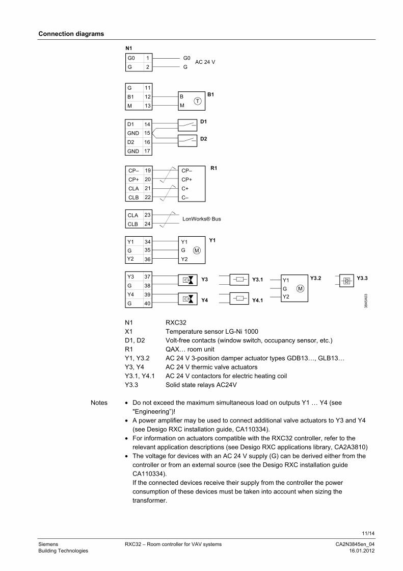
Connection diagrams
M
Y3.2
Y2
G
Y1Y3.1
Y4.1
N1
38
45
A0
3
1
2
G0
GAC 24 V
G0
G
11
12
13
G
B1
MT
B1B
M
14
15
16
D1
GND
D2
D1
D2
17GND
23
24
CLA
CLB
R119
20
21
22
CP–
CP+
CLA
CLB
CP–
CP+
C+
C–
37
38
39
40
Y3
G
Y4
G
Y3
Y4
G
Y2
Y1 Y134
35
36
Y1
G
Y2
M
Y3.3
LonWorks® Bus
N1 RXC32 X1 Temperature sensor LG-Ni 1000 D1, D2 Volt-free contacts (window switch, occupancy sensor, etc.) R1 QAX… room unit Y1, Y3.2 AC 24 V 3-position damper actuator types GDB13…, GLB13… Y3, Y4 AC 24 V thermic valve actuators Y3.1, Y4.1 AC 24 V contactors for electric heating coil Y3.3 Solid state relays AC24V • Do not exceed the maximum simultaneous load on outputs Y1 … Y4 (see
"Engineering”)! • A power amplifier may be used to connect additional valve actuators to Y3 and Y4
(see Desigo RXC installation guide, CA110334). • For information on actuators compatible with the RXC32 controller, refer to the
relevant application descriptions (see Desigo RXC applications library, CA2A3810) • The voltage for devices with an AC 24 V supply (G) can be derived either from the
controller or from an external source (see the Desigo RXC installation guide CA110334). If the connected devices receive their supply from the controller the power consumption of these devices must be taken into account when sizing the transformer.
Notes
12/14
Siemens RXC32 – Room controller for VAV systems CA2N3845en_04 Building Technologies 16.01.2012
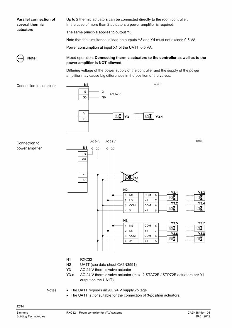
Up to 2 thermic actuators can be connected directly to the room controller. In the case of more than 2 actuators a power amplifier is required.
The same principle applies to output Y3.
Note that the simultaneous load on outputs Y3 and Y4 must not exceed 9.5 VA.
Power consumption at input X1 of the UA1T: 0.5 VA. Mixed operation: Connecting thermic actuators to the controller as well as to the power amplifier is NOT allowed.
Differing voltage of the power supply of the controller and the supply of the power amplifier may cause big differences in the position of the valves.
AC 24 V
00105 H
Y3
N1
Y1
G
G
G0
Y3.1
G
G0
1
2
3
4
NS
LS
COM
X1
AC 24 V
Y3.1
Y3.2
00105 K
Y3
8
7
6
5
COM
Y1
COM
Y1
N2
1
2
3
4
NS
LS
COM
X1
Y3.5
Y3.6
8
7
6
5
COM
Y1
COM
Y1
N2
G G0
Y3.3
Y3.4
Y3.7
Y3.8
N1
Y1
G
G G0
AC 24 V
G
G0
N1 RXC32 N2 UA1T (see data sheet CA2N3591) Y3 AC 24 V thermic valve actuator Y3.x AC 24 V thermic valve actuator (max. 2 STA72E / STP72E actuators per Y1
output on the UA1T) • The UA1T requires an AC 24 V supply voltage • The UA1T is not suitable for the connection of 3-position actuators.
Parallel connection of several thermic actuators
STOP Note!
Connection to controller
Connection to power amplifier
Notes
13/14
Siemens RXC32 – Room controller for VAV systems CA2N3845en_04 Building Technologies 16.01.2012
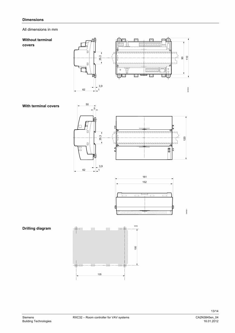
Dimensions
62 1
3,9
35,3
384
5M0
211
0
90
62 1
3,9
35,3
384
5M0
112
0152
50
5
161
100
135
80056
All dimensions in mm
Without terminal covers
With terminal covers
Drilling diagram
14/14
Siemens RXC32 – Room controller for VAV systems CA2N3845en_04 Building Technologies 16.01.2012
2000 - 2012 Siemens Switzerland Ltd. Subject to change