![Multi Air Conditioner SVC MANUAL(Exploded View) Multi Air Conditioner SVC MANUAL(Exploded View) MODEL : AMNW09GAF11 [LMAN097HVP] AMNW12GAF11 [LMAN127HVP] CAUTION Before Servicing the](https://static.fdocuments.in/doc/165x107/5e13e9ca44f020744d02cf7d/multi-air-conditioner-svc-manualexploded-view-multi-air-conditioner-svc-manualexploded.jpg)
Room Air Conditioner SVC MANUAL(Exploded View)angol)/RAC/SxyAW... · Before Servicing the unit,...
84
Room Air Conditioner SVC MANUAL(Exploded View) MODEL : AS-W0964DH0/GH0 AS-W0964DH1 AS-W1264DH0/GH0 AS-W1865DH0 AS-W1224DH0 AS-W1424DH0 AS-W1825DH0 AS-W096E1G0 AS-W126E1G0 CAUTION Before Servicing the unit, read the safety precautions in General SVC manual. Only for authorized service personnel. Internal Use Only http://biz.lgservice.com
Transcript of Room Air Conditioner SVC MANUAL(Exploded View)angol)/RAC/SxyAW... · Before Servicing the unit,...
Room Air ConditionerSVC MANUAL(Exploded View)MODEL : AS-W0964DH0/GH0
AS-W0964DH1AS-W1264DH0/GH0AS-W1865DH0AS-W1224DH0AS-W1424DH0AS-W1825DH0AS-W096E1G0AS-W126E1G0
CAUTIONBefore Servicing the unit, read the safety precautions in General SVC manual.Only for authorized service personnel.
Internal Use Only
http://biz.lgservice.com

- 2 -Copyright ©2007 LG Electronics. Inc. All right reserved.Only for training and service purposes LGE Internal Use Only
Air Conditioner Service Manual
TABLE OF CONTENTS
LG Model Name.................................................................................................................................3
Safety Precautions ...........................................................................................................................5
Dimensions .....................................................................................................................................10
Installation.......................................................................................................................................14
Connecting the cable between indoor unit and outdoor unit.....................................................24
Checking the drainage and forming the pipings .........................................................................26
Air purging ......................................................................................................................................27
Test running ....................................................................................................................................29
Functions.........................................................................................................................................30
Operation.........................................................................................................................................33
Disassembly ....................................................................................................................................44
Troubleshooting Guide ..................................................................................................................47
Schematic Diagram ........................................................................................................................67
Product Specifications ..................................................................................................................76
Exploded View ................................................................................................................................80

- 3 -Copyright ©2007 LG Electronics. Inc. All right reserved.Only for training and service purposes LGE Internal Use Only
LG Model Name
LG Model Name2003
1 2 - 3 4 5 6 7 8 9 10
Code Type Code of Model Meaning
1 Producing Center, A~Z L: Chang-won R22 N: IndiaRefrigerant A: Chang-won R410A Z: Brazil
C: Chang-won R407C D: IndonesiaT: China M: MexicoK: Turkey R22 V: VietnamE: Turkey R410A S: Out SourcingH: Thailand
2 Product Type A~Z S: Split Type Air Conditioner
3 Cooling/Heating/Inverter A~Z C: Cooling onlyH: Heat pumpX: C/O + E/HeaterZ: H/P + E/Heater
V: AC Inverter C/ON: AC Inverter H/PQ: DC Inverter C/OW: DC Inverter H/P
4, 5 Capacity 0~9 Cooling/Heating CapacityEx. "09" 9,000 Btu/h
6 Electric Range 1~9 1: 115V/60Hz, A: 220V, 50Hz, 3PhaseA~Z 2: 220V/60Hz B: 208~230V, 60Hz, 3Phase
3: 208-230V/60Hz C: 575V, 50Hz, 3Phase5: 200-220V/50Hz D: 440~460, 60Hz, 3Phase6: 220-240V/50Hz E: 265V, 60Hz7: 110V, 50/60Hz F: 200V, 50/60Hz8: 380-415V/50Hz9: 380-415V/60Hz
7 Chassis A~Z Name of Chassis of UnitEx. 4 S4 Chassis
8 Look A~Z Look,Color (Artcool Model)
9 Function A~Z
10 Serial No. 0~9 LG Model De
* ARTCOOL COLOR
velopment Serial No.
Basic ABasic+4Way BPlasma Filter CPlasma Filter+4 Way DTele+LCD ETele+LCD+Nano plasma+4Way FNano Plasma F+(A/changeove)+A/clean+Low A GNano Plasma F+(A/changeove)+A/clean+4way+Low A HTele+LED+4way IInternet JPlasma F+4Way+Oxy generator KNano Plasma F+(A/changeove)+A/clean LNano Plasma F+(A/changeove)+A/clean+4way MNano Plasma F+(A/changeove)+A/clean+PTC NNano Plasma F+(A/changeove)+Autoclean+4way+PTC PNano Plasma F+(A/changeove)+A/clean+4way+Low A+PTC QNegative ION+A/Clean R(Nano)Plasma+Negative ION+A/Clean S4way+(Nano)Plasma F+Negative ION+Healthy dehumidification+A/Clean TNano Plasma F+4Way+(A/changeove)+A/clean+ U
R MirrorW WhiteB BlueD WoodM MetalC Cherry
N WalnutA GoghS SisleyQ QuranK Mecca

- 4 -Copyright ©2007 LG Electronics. Inc. All right reserved.Only for training and service purposes LGE Internal Use Only
LG Model Name
2004~
1 2 - 3 4 5 6 7 8 9 10
Code Type Code of Model Meaning
1 Producing Center, A~Z L Chang_won R22 A Chang_won R410A C Chang_won R407C T China K Turkey R22 E Turkey R410A H Thailand
N India Z Brazil D Indonesia X Mexico V Vietnam S Out sourcing
Refrigerant
2 Product Type A~Z S: Split Type Air Conditioner
3 Cooling/Heating/Inverter A~Z C: Cooling onlyH: Heat pumpX: C/O + E/HeaterZ: H/P + E/Heater
V: AC Inverter C/ON: AC Inverter H/PQ: DC Inverter C/OW: DC Inverter H/P
4, 5 Capacity 0~9 Cooling/Heating CapacityEx. "09" 9,000 Btu/h
6 Electric Range 1~9 1: 115V/60Hz, A: 220V, 50Hz, 3PhaseA~Z 2: 220V/60Hz B: 208~230V, 60Hz, 3Phase
3: 208-230V/60Hz C: 575V, 50Hz, 3Phase5: 200-220V/50Hz D: 440~460, 60Hz, 3Phase6: 220-240V/50Hz E: 265V, 60Hz7: 110V, 50/60Hz F: 200V
CHASSIS LookDG1KLGMNDP
DivisionPanel Type(Deluxe)Grille TypePanel Type(Deluxe)Fighting 'Look'(LG1)(LG2)-SEMI PANELOEM1OEM2Panel Type(Deluxe)LG3
, 50/60Hz8: 380-415V/50Hz9: 380-415V/60Hz
7 Chassis A~Z Name of Chassis of UnitEx. 4S4 Chassis 8 Look A~Z Look,Color (Artcool Model)
9 Function A~Z
10 Serial No. 0~9 LG Model De
* ARTCOOL COLOR
velopment Serial No.
R MirrorW WhiteB BlueD WoodM MetalC Cherry
S4/S5/SD
SES6SQSRST
Basic ABasic+4Way BPlasma Filter CPlasma Filter+4 Way DTele+LCD ETele+LCD+Nano plasma+4Way FNBF F+(A/changeove)+A/clean+Low A GNBF F+(A/changeove)+A/clean+4way+Low A HTele+LED+4way IInternet JPlasma F+4Way+Oxy generator KNBF F+(A/changeove)+A/clean LNBF F+(A/changeove)+A/clean+4way MNBF F+(A/changeove)+A/clean+PTC NNBF F+(A/changeove)+Autoclean+4way+PTC PNBF F+(A/changeove)+A/clean+4way+Low A+PTC Q(Nano)Plasma+ION+A/Clean S4way+(Nano)Plasma F+Negative ION+Healthy dehumidification+A/Clean TNano Plasma F+4Way+(A/changeove)+A/clean+Oxy generator U4way+(Nano)Plasma F+Negative ION+Healthy dehumidification+A/Clean+Oxy generator VDry contact WWire remocon 8

- 5 -Copyright ©2007 LG Electronics. Inc. All right reserved.Only for training and service purposes LGE Internal Use Only
Safety Precautions
Safety Precautions
To prevent injury to the user or other people and property damage, the following instructions mustbe followed. Incorrect operation due to ignoring instruction will cause harm or damage. The seriousness is
classified by the following indications.
Meanings of symbols used in this manual are as shown below.
This symbol indicates the possibility of death or serious injury.
This symbol indicates the possibility of injury or damage to properties only.
Be sure not to do.
Be sure to follow the instruction.
Do not use damaged power cords, plugs, or aloose socket.
Always use the power plug and socket with theground terminal.
• There is risk of fire of electric shock. • There is risk of electric shock.
Install the panel and the cover of control boxsecurely.
Do not modify or extend the power cord.
• There is risk of fire of electric shock. • No grounding may cause electric shock.
Installation

- 6 -Copyright ©2007 LG Electronics. Inc. All right reserved.Only for training and service purposes LGE Internal Use Only
Safety Precautions
Do not install the product on a defective instal-lation stand.
Be sure the installation area does not deteriorate with age.
• It may cause injury, accident, or damage to theproduct.
• If the base collapses, the air conditioner could fallwith it, causing property damage, product failure,and personal injury.
• Sharp edges could cause injury. Be especially care-ful of the case edges and the fins on the condenserand evaporator.
• There is risk of fire, electric shock, explosion, or injury.
Be cautious when unpacking and installing theproduct.
For installation, always contact the dealer oran Authorized service center
For re-installation of the installed product,always contact a dealer or an authorized ser-vice center.
Do not install, remove, or re-install the unit byyourself.
• There is risk of fire, electric shock, explosion, orinjury.
• There is risk of fire, electric shock, explosion, orinjury.

- 7 -Copyright ©2007 LG Electronics. Inc. All right reserved.Only for training and service purposes LGE Internal Use Only
Safety Precautions
Operation
Do not turn the air-conditioner ON or OFF byplugging or unplugging the power plug.
Use a dedicated outlet for this appliance.
• There is risk of fire or electrical shock. • There is risk of fire or electrical shock.
Grasp the plug to remove the cord from theoutlet. Do not touch it with wet hands.
Do not place a heater or other appliances nearthe power cable.
• There is risk of fire or electrical shock. • There is risk of fire and electric shock.
Do not allow water to run into electrical parts. Do not store or use flammable gas or com-bustibles near the air conditioner.
• There is risk of fire, failure of the product, or electricshock.
• There is risk of fire or failure of product.
Wax Thinner
- 8 -Copyright ©2007 LG Electronics. Inc. All right reserved.Only for training and service purposes LGE Internal Use Only
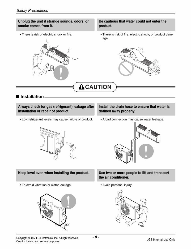
Always check for gas (refrigerant) leakage afterinstallation or repair of product.
Install the drain hose to ensure that water isdrained away properly.
• Low refrigerant levels may cause failure of product. • A bad connection may cause water leakage.
Keep level even when installing the product. Use two or more people to lift and transportthe air conditioner.
• To avoid vibration or water leakage. • Avoid personal injury.
Installation
90˚
Unplug the unit if strange sounds, odors, orsmoke comes from it.
Be cautious that water could not enter theproduct.
• There is risk of electric shock or fire. • There is risk of fire, electric shock, or product dam-age.
Safety Precautions

- 9 -Copyright ©2007 LG Electronics. Inc. All right reserved.Only for training and service purposes LGE Internal Use Only
Use a soft cloth to clean. Do not use harshdetergents, solvents, etc.
Do not touch the metal parts of the productwhen removing the air filter. They are verysharp!
• There is risk of fire, electric shock, or damage to theplastic parts of the product.
• There is risk of personal injury.
Do not step on or put anyting on the product.(outdoor units)
Do not insert hands or other objects throughthe air inlet or outlet while the air conditioneris plugged in.
• There is risk of personal injury and failure of product. • There are sharp and moving parts that could causepersonal injury.
Operation
Wax
Safety Precautions
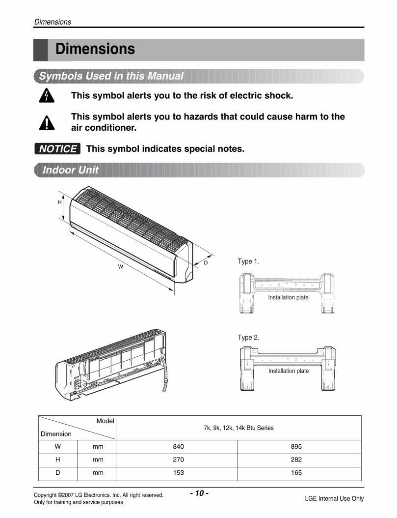
D
H
W
Installation plate
Installation plate
Type 1.
Type 2.
- 10 -Copyright ©2007 LG Electronics. Inc. All right reserved.Only for training and service purposes LGE Internal Use Only
Dimensions
Dimensions
W mm 840 895
H mm 270 282
D mm 153 165
Model
Dimension7k, 9k, 12k, 14k Btu Series
Indoor Unit
This symbol alerts you to the risk of electric shock.
This symbol alerts you to hazards that could cause harm to theair conditioner.
This symbol indicates special notes.NOTICE
Symbols Used in this Manual

- 11 -Copyright ©2007 LG Electronics. Inc. All right reserved.Only for training and service purposes LGE Internal Use Only
Dimensions
D
H
W
Installation plate
Installation plate
Type 1.
Type 2.
W mm 1090
H mm 300
D mm 178
Model
Dimension18k, 24k Btu Series
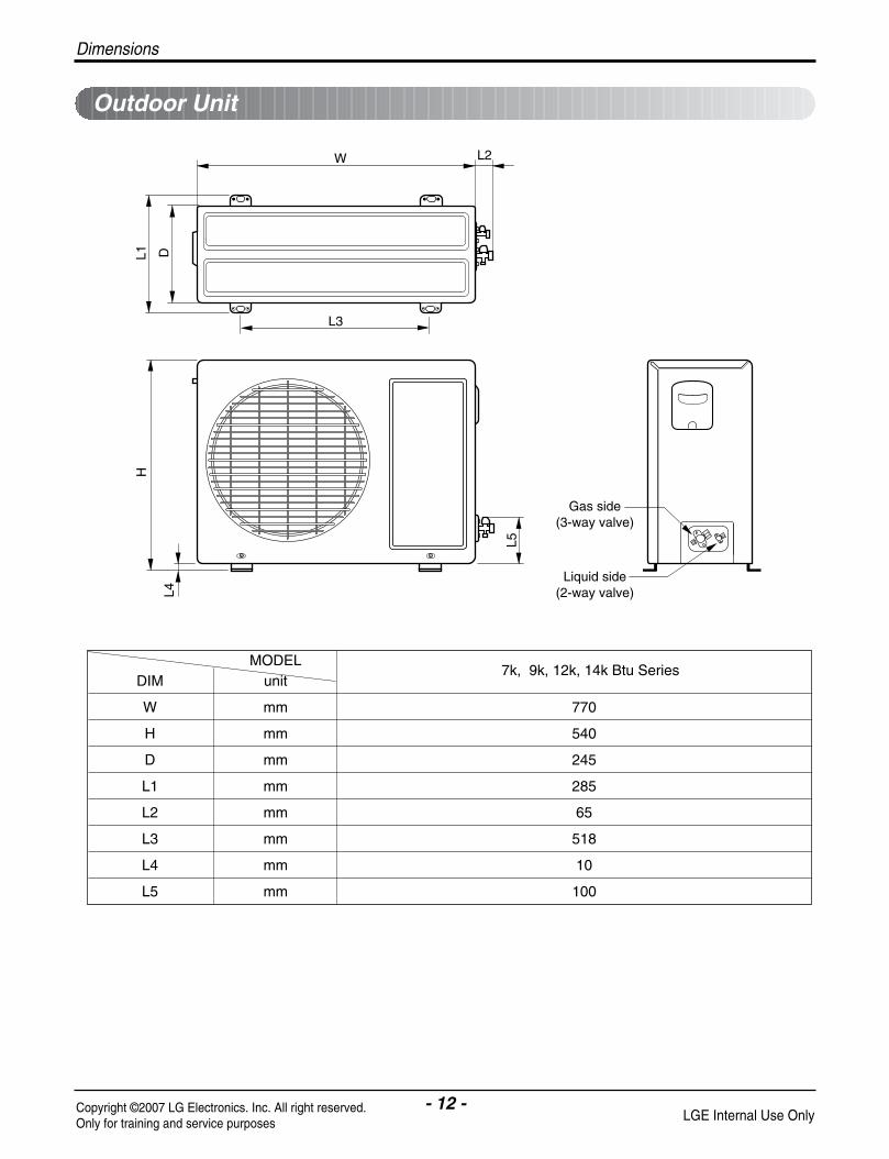
W L2
L3
L1 D
H
L4
L5Gas side
(3-way valve)
Liquid side(2-way valve)
MODELDIM unit
W mm 770
H mm 540
D mm 245
L1 mm 285
L2 mm 65
L3 mm 518
L4 mm 10
L5 mm 100
Dimensions
- 12 -Copyright ©2007 LG Electronics. Inc. All right reserved.Only for training and service purposes LGE Internal Use Only
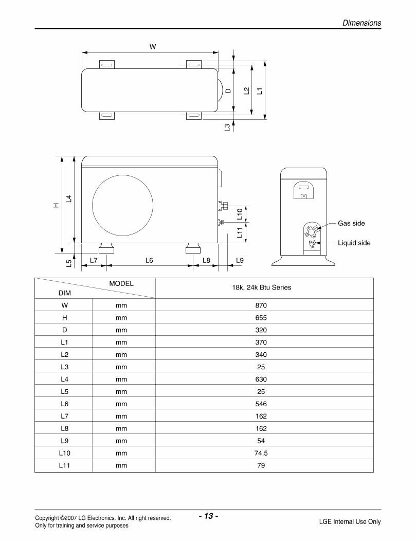
Outdoor Unit
7k, 9k, 12k, 14k Btu Series
Dimensions
- 13 -Copyright ©2007 LG Electronics. Inc. All right reserved.Only for training and service purposes LGE Internal Use Only
W
L7 L6 L8 L9
D L1L2
L3
L10
L11
L4L5
H
Gas side
Liquid side
MODELDIM
W mm 870
H mm 655
D mm 320
L1 mm 370
L2 mm 340
L3 mm 25
L4 mm 630
L5 mm 25
L6 mm 546
L7 mm 162
L8 mm 162
L9 mm 54
L10 mm 74.5
L11 mm 79
18k, 24k Btu Series

- 14 -Copyright ©2007 LG Electronics. Inc. All right reserved.Only for training and service purposes LGE Internal Use Only
Installation
Installation
Indoor unit1. Do not have any heat or steam near the unit.
2. Select a place where there are no obstacles in frontof the unit.
3. Make sure that condensation drainage can be conve-niently routed away.
4. Do not install near a doorway.
5. Ensure that the interval between a wall and the left(or right) of the unit is more than 10cm. The unitshould be installed as high as possible on the wall,allowing a minimum of 20cm from ceiling.
6. Use a stud finder to locate studs to prevent unneces-sary damage to the wall.
Outdoor unit1. If an awning is built over the unit to prevent direct
sunlight or rain exposure, make sure that heat radia-tion from the condenser is not restricted.
2. Ensure that the space around the back and sides ismore than 30cm. The front of the unit should havemore than 70cm of space.
3. Do not place animals and plants in the path of thewarm air.
4. Take the weight of the air conditioner into accountand select a place where noise and vibration are min-imum.
5. Select a place where the warm air and noise from theair conditioner do not disturb neighbors.
Select the best Location
More than 20cm
More than10cm
More than 1.5m
More than10cm
Install the indoor unit on the wall where the height from the floor is more than 1.5 meters.
More than 30cm More than 30cm
More than 60cm
More than 60cm
More than 70cm

- 15 -Copyright ©2007 LG Electronics. Inc. All right reserved.Only for training and service purposes LGE Internal Use Only
Installation
Piping Length and Elevation
7k, 8k, 9k 3/8" 1/4" 4 or 7.5 7 15 20
11k, 12k, 14k3/8" 1/4" 4 or 7.5 7 15 20
1/2" 1/4" 4 or 7.5 7 15 20
1/2" 1/4" 4 or 7.5 15 30 20
18k, 24k, 26k 5/8" 1/4" 4 or 7.5 15 30 20
5/8" 3/8" 4 or 7.5 15 30 30
Pipe SizeCapacity(Btu/h) GAS LIQUID
Max. Length A (m)
Additional Refrigerant(g/m)
Max.Elevation B (m)
StandardLength (m)
Outdoor unit
Indoor unit
A
B
Outdoor unit
Indoor unit
A
B
AOil trap
Outdoor unit
Indoor unitB
If the piping length is more 10 Meters and the outdoor
Capacity is based on standard length and maximum allowance length is on the basis of reliability.Oil trap should be installed every 5~7 meters.

- 16 -Copyright ©2007 LG Electronics. Inc. All right reserved.Only for training and service purposes LGE Internal Use Only
Installation
The wall you select should be strong and solidenough to prevent vibration
1. Mount the installation plate on the wall with type "A" screws. If mounting the unit on a concretewall, use anchor bolts.
• Mount the installation plate horizontally by aligningthe centerline using a level.
2. Measure the wall and mark the centerline. It is alsoimportant to use caution concerning the location ofthe installation plate-routing of the wiring to poweroutlets is through the walls typically. Drilling thehole through the wall for piping connections mustbe done safely.
Fixing Installation Plate
Installation Plate
Type "A" screw
ChassisHook
Installation plate
Left rear piping Right rear pipingØ70mm Ø70mm
D B
AC
• Drill the piping hole with a ø70mm hole core drill.Drill the piping hole at either the right or the left withthe hole slightly slanted to the outdoor side.
Drill a Hole in the Wall
5-7m
m
(3/1
6"~
5/16
")
Indoor
WALL
Outdoor
A B C D
S4 73 55 82 55
S5 121 62 258 62
CHASSIS(Grade)
Distance (mm)
A B C D
S4 50 105 59 105
SE 65 110 85 110
S5 95 122 235 122
CHASSIS(Grade)
Distance (mm)
Installation plate
Left rear piping Right rear pipingØ70mm Ø70mm
D B
AC
Type 1.
Type 1.
Type 2.Type 2.

- 17 -Copyright ©2007 LG Electronics. Inc. All right reserved.Only for training and service purposes LGE Internal Use Only
Installation
Flaring WorkMain cause for gas leakage is due to defect in flaring work. Carry out correct flaring work in the following procedure.
Cut the pipes and the cable.1. Use the piping kit accessory or the pipes purchased locally.
2. Measure the distance between the indoor and the outdoorunit.
3. Cut the pipes a little longer than measured distance.
4. Cut the cable 1.5m longer than the pipe length.
Burrs removal1. Completely remove all burrs from the cut cross section of
pipe/tube.
2. Put the end of the copper tube/pipe in a downward directionas you remove burrs in order to avoid dropping burrs into thetubing.
Putting nut on• Remove flare nuts attached to indoor and outdoor unit, then
put them on pipe/tube having completed burr removal.(not possible to put them on after flaring work)
Flaring work1. Firmly hold copper pipe in a die in the dimension shown in the table below.2. Carry out flaring work with the flaring tool.
Copperpipe 90° Slanted Uneven Rough
Pipe
Reamer
Point down
Flare nut
Copper tube
mm inch mmØ6.35 1/4" 1.1~1.3Ø9.52 3/8" 1.5~1.7Ø12.7 1/2" 1.6~1.8Ø15.88 5/8" 1.6~1.8Ø19.05 3/4" 1.9~2.1
Outside diameter A
Bar
Copper pipe
Clamp handleRed arrow mark
Cone
Yoke
Handle
Bar"A"

- 18 -Copyright ©2007 LG Electronics. Inc. All right reserved.Only for training and service purposes LGE Internal Use Only
Installation
Check1. Compare the flared work with the figure by.
2. If a flared section is defective, cut it off and do flaringwork again.
Indoor1. Prepare the indoor unit's piping and drain hose for installation through the wall.
2. Remove the plastic tubing retainer(see the illustrationby) and pull the tubing and drain hose away fromchassis.
3. Replace only the plastic tubing holder 1, not the hold-er 2 in the original position.
1. Route the indoor tubing and the drain hose in thedirection of rear right.
2. Insert the connecting cable into the indoor unit from theoutdoor unit through the piping hole.• Do not connect the cable to the indoor unit.• Make a small loop with the cable for easy connec-
tion later.
3. Tape the tubing, drain hose, and the connectingcable. Be sure that the drain hose is located at thelowest side of the bundle. Locating at the uper sidecan cause drain pan to overflow inside the unit.
If the drain hose is routed inside the room, insulate thehose with an insulation material* so that dripping from"sweating"(condensation) will not damage furniture orfloors.*Foamed polyethylene or equivalent is recommended.
Inclined
Inside is shiny without scratches
Smooth all round
Even lengthall round
Surfacedamaged
Cracked Uneventhickness
= Improper flaring =
Connecting the Piping
For right rear piping
Drain hose
Connecting pipe
Connecting cable
Tape
Drain hose

- 19 -Copyright ©2007 LG Electronics. Inc. All right reserved.Only for training and service purposes LGE Internal Use Only
Installation
4. Indoor unit installationHook the indoor unit onto the upper portion of theinstallation plate.(Engage the two hooks of the reartop of the indoor unit with the upper edge of theinstallation plate.) Ensure that the hooks are properlyseated on the installation plate by moving it left andright.
Press the lower left and right sides of the unit againstthe installation plate until the hooks engage into theirslots(clicking sound).
Connecting the piping to the indoor unit and drainhose to drain pipe.
1. Align the center of the pipes and sufficiently tightenthe flare nut by hand.
2. Tighten the flare nut with a wrench.
3. Mount the clamp on the boss with a type "B"screw.(optional)
4. When extending the drain hose at the indoor unit,install the drain pipe.
Wrap the insulation material around the connectingportion.
1. Overlap the connection pipe insulation material andthe indoor unit pipe insulation material. Bind themtogether with vinyl tape so that there may be no gap.
2. Wrap the area which accommodates the rear pipinghousing section with vinyl tape.
3. Bundle the piping and drain hose together by wrap-ping them with vinyl tape for enough to cover wherethey fit into the rear piping housing section.
Drain hose
Connectingcable
Indoor unit tubing Flare nut Pipes
Wrench
Indoor unit tubing
Open-end wrench (fixed)
Connection pipe
Flare nut
Vinyl tape(narrow)Adhesive
Drain pipe
Indoor unit drain hose
Drain hoseClamp
Boss
Type "B" screw
Plastic bands Insulation material
Vinyl tape(narrow)
Connection pipe
Connecting cableVinyl tape (wide) Wrap with vinyl tape
Indoor unit pipe
Pipe
Wrap with vinyl tape
Drain hose
Pipe
Vinyl tape(wide)
mm inch kg.mØ6.35 1/4" 1.1~1.3Ø9.52 3/8" 1.5~1.7Ø12.7 1/2" 1.6~1.8Ø15.88 5/8" 1.6~1.8Ø19.05 3/4" 1.9~2.1
Outside diameter Torque

- 20 -Copyright ©2007 LG Electronics. Inc. All right reserved.Only for training and service purposes LGE Internal Use Only
Installation
1. Route the indoor tubing and the drain hose to therequired piping hole position.
2. Insert the piping, drain hose, and the connectingcable into the piping hole.
3. Insert the connecting cable into the indoor unit.• Don't connect the cable to the indoor unit.• Make a small loop with the cable for easy connec-
tion later.
4. Tape the drain hose and the connecting cables.
5. Indoor unit installation• Hang the indoor unit from the hooks at the top of the
installation plate.• Insert the spacer etc. between the indoor unit and
the installation plate and separate the bottom of theindoor unit from the wall.
Connecting the piping to the indoor unit and thedrain hose to drain pipe.1. Align the center of the pipes and sufficiently tighten
the flare nut by hand.
2. Tighten the flare nut with a wrench.
3. When extending the drain hose at the indoor unit,install the drain pipe.
For left rear piping
Drain pipe
Connectingcable
1 2
Installation plate
SpacerIndoor unit
8cm
Indoor unit tubing Flare nut Pipes
Wrench
Indoor unit tubing
Connection pipe
Flare nut
Open-end wrench (fixed)
Vinyl tapeAdhesive
Drain hose
Indoor unit drain hose
(narrow)
mm inch kg.mØ6.35 1/4" 1.1~1.3Ø9.52 3/8" 1.5~1.7Ø12.7 1/2" 1.6~1.8Ø15.88 5/8" 1.6~1.8Ø19.05 3/4" 1.9~2.1
Outside diameter Torque

- 21 -Copyright ©2007 LG Electronics. Inc. All right reserved.Only for training and service purposes LGE Internal Use Only
Installation
Wrap the insulation material around the connectingportion.1. Overlap the connection pipe heat insulation and the
indoor unit pipe heat insulation material. Bind themtogether with vinyl tape so that there may be no gap.
2. Wrap the area which accommodates the rear pipinghousing section with vinyl tape.
3. Bundle the piping and drain hose together by wrap-ping them with cloth tape over the range within whichthey fit into the rear piping housing section.
Reroute the pipings and the drain hose across theback of the chassis.
Indoor unit installation 1. Remove the spacer.
2. Ensure that the hooks are properly seated on theinstallation plate by moving it left and right.
3. Press the lower left and right sides of the unit againstthe installation plate until the hooks engage into theirslots(clicking sound).
Plastic bands Insulation material
Vinyl tape(narrow)
Connectionpipe
Connecting cable
Indoor unit piping
Pipe
Vinyl tape(wide)
Wrap with vinyl tape
Drain hoseVinyl tape(narrow)
Pipe
Wrap with vinyl tape(wide)
Piping forpassage throughpiping hole
Drain hose
Connectingcable

- 22 -Copyright ©2007 LG Electronics. Inc. All right reserved.Only for training and service purposes LGE Internal Use Only
Installation
Installation Information. For left piping. Follow the instruction below.
Good case• Press on the upper side of clamp and unfold the tubing to downward slowly.
Bad case• Following bending type from right to left may cause damage to the tubing.

- 23 -Copyright ©2007 LG Electronics. Inc. All right reserved.Only for training and service purposes LGE Internal Use Only
Installation
OutdoorAlign the center of the pipings and sufficiently tightenthe flare nut by hand.
Finally, tighten the flare nut with torque wrench until thewrench clicks.
• When tightening the flare nut with torque wrench,ensure the direction for tightening follows the arrow onthe wrench.
mm inch kgf.mØ6.35mm 1/4" 1.8~2.5Ø9.52mm 3/8" 3.4~4.2Ø12.7mm 1/2" 5.5~6.6Ø15.88mm 5/8" 6.3~8.2Ø19.05mm 3/4" 9.9~12.1
Outside diameter Torque
Outdoor unit Liquid side piping(Smaller diameter)
Gas sidepiping(Biggerdiameter)
Torque wrench
- 24 -Copyright ©2007 LG Electronics. Inc. All right reserved.Only for training and service purposes LGE Internal Use Only
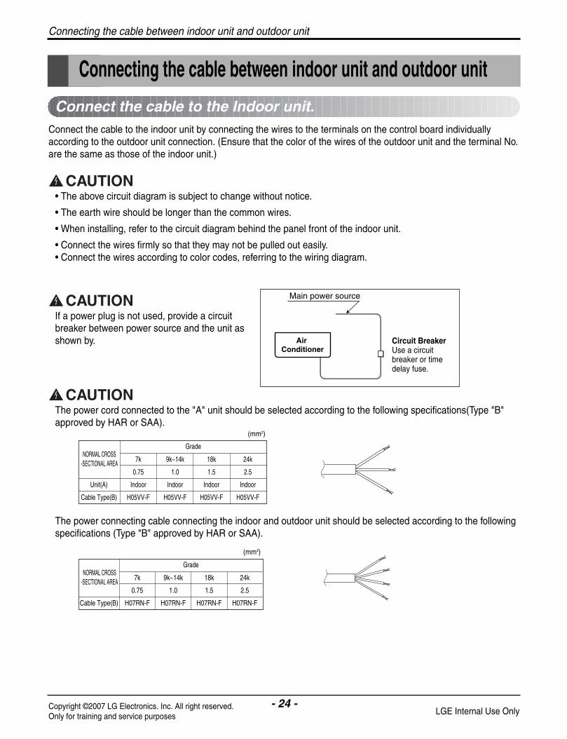
Connect the cable to the Indoor unit.
Connecting the cable between indoor unit and outdoor unit
Connect the cable to the indoor unit by connecting the wires to the terminals on the control board individuallyaccording to the outdoor unit connection. (Ensure that the color of the wires of the outdoor unit and the terminal No.are the same as those of the indoor unit.)
• The above circuit diagram is subject to change without notice.
• The earth wire should be longer than the common wires.
• When installing, refer to the circuit diagram behind the panel front of the indoor unit.
• Connect the wires firmly so that they may not be pulled out easily.• Connect the wires according to color codes, referring to the wiring diagram.
If a power plug is not used, provide a circuitbreaker between power source and the unit asshown by.
The power cord connected to the "A" unit should be selected according to the following specifications(Type "B"approved by HAR or SAA).
The power connecting cable connecting the indoor and outdoor unit should be selected according to the followingspecifications (Type "B" approved by HAR or SAA).
Air Conditioner
Main power source
7k 9k~14k 18k 24k
0.75 1.0 1.5 2.5
Unit(A) Indoor Indoor Indoor Indoor
Cable Type(B) H05VV-F H05VV-F H05VV-F H05VV-F
NORMAL CROSS-SECTIONAL AREA
Grade
(mm2)
7k 9k~14k 18k 24k
0.75 1.0 1.5 2.5
Cable Type(B) H07RN-F H07RN-F H07RN-F H07RN-F
NORMAL CROSS-SECTIONAL AREA
Grade
(mm2)
Circuit BreakerUse a circuitbreaker or timedelay fuse.
Connecting the cable between indoor unit and outdoor unit
- 25 -Copyright ©2007 LG Electronics. Inc. All right reserved.Only for training and service purposes LGE Internal Use Only
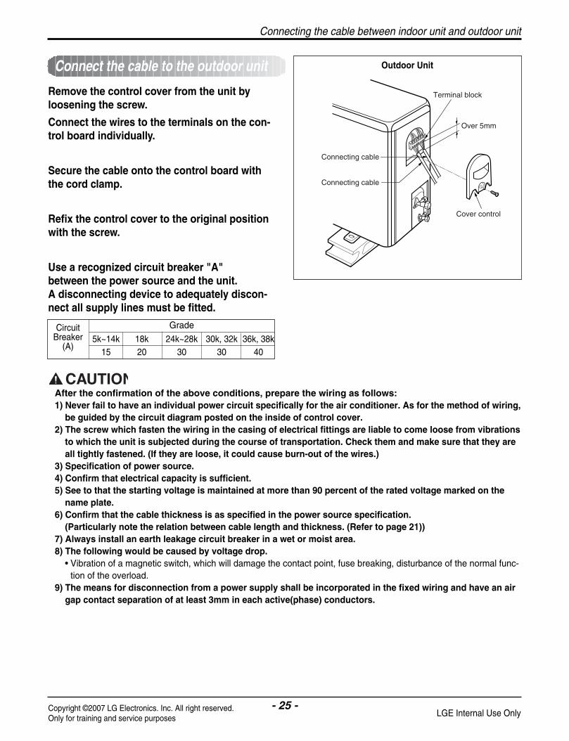
Remove the control cover from the unit byloosening the screw.
Connect the wires to the terminals on the con-trol board individually.
Secure the cable onto the control board withthe cord clamp.
Refix the control cover to the original positionwith the screw.
Use a recognized circuit breaker "A" between the power source and the unit. A disconnecting device to adequately discon-nect all supply lines must be fitted.
Terminal block
Over 5mm
Cover control
Connecting cable
Connecting cable
After the confirmation of the above conditions, prepare the wiring as follows:1) Never fail to have an individual power circuit specifically for the air conditioner. As for the method of wiring,
be guided by the circuit diagram posted on the inside of control cover.2) The screw which fasten the wiring in the casing of electrical fittings are liable to come loose from vibrations
to which the unit is subjected during the course of transportation. Check them and make sure that they areall tightly fastened. (If they are loose, it could cause burn-out of the wires.)
3) Specification of power source.4) Confirm that electrical capacity is sufficient.5) See to that the starting voltage is maintained at more than 90 percent of the rated voltage marked on the
name plate.6) Confirm that the cable thickness is as specified in the power source specification.
(Particularly note the relation between cable length and thickness. (Refer to page 21))7) Always install an earth leakage circuit breaker in a wet or moist area.8) The following would be caused by voltage drop.
• Vibration of a magnetic switch, which will damage the contact point, fuse breaking, disturbance of the normal func-tion of the overload.
9) The means for disconnection from a power supply shall be incorporated in the fixed wiring and have an airgap contact separation of at least 3mm in each active(phase) conductors.
Outdoor UnitConnect the cable to the outdoor unit
5k~14k 18k 24k~28k 30k, 32k 36k, 38k15 20 30 30 40
CircuitBreaker
(A)
Grade
Connecting the cable between indoor unit and outdoor unit

- 26 -Copyright ©2007 LG Electronics. Inc. All right reserved.Only for training and service purposes LGE Internal Use Only
Checking the drainage and forming the pipings
Checking the drainage Form the pipingForm the piping by wrapping the connectingportion of the indoor unit with insulation mate-rial and secure it with two kinds of vinyl tapes.• If you want to connect an additional drain hose, the end of
the drain outlet should be routed above the ground. Securethe drain hose appropriately.
In cases where the outdoor unit is installedbelow the indoor unit perform the following.• Tape the piping, drain hose and connecting cable from
down to up.
• Secure the tapped piping along the exterior wall using sad-dle or equivalent.
To check the drainage.• Pour a glass of water on the evaporator.
• Ensure the water flows through the drain hose of the indoorunit without any leakage and goes out the drain exit.
To remove the front panel from the indoor unit.• Set the air direction louvers up-and-down to the
position(horizontally)by hand.
• Remove the securing screws that retain the front panel.Pull the lower left and right sides of the grille toward youand lift it off.
In cases where the Outdoor unit is installedabove the Indoor unit perform the following.• Tape the piping and connecting cable from down to up.
• Secure the taped piping along the exterior wall. Form a trapto prevent water entering the room.
• Fix the piping onto the wall by saddle or equivalent.
Drain piping• The drain hose should point downward for easy drain flow.
• Do not make drain piping.
Pull the right andthe left side.
Downward slope
Do not raiseAccumulateddrain water
Tip of drain hose dipped in water
Air
WavingWaterleakage
Waterleakage Ditch
Less than 50mm gap
Waterleakage
Taping
Drainhose
Pipings
Connectingcable
Trap is required to prevent waterfrom entering into electrical parts.
Seal small openingsaround pipings with agum type sealer.
Seal a small opening around the pipings with gum type sealer.
Trap
Trap
Checking the drainage and forming the pipings
- 27 -Copyright ©2007 LG Electronics. Inc. All right reserved.Only for training and service purposes LGE Internal Use Only
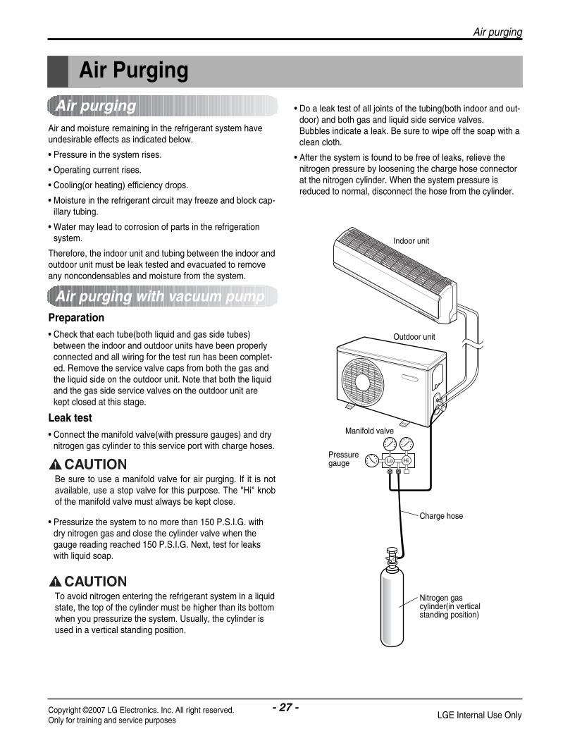
Air purging
Air and moisture remaining in the refrigerant system haveundesirable effects as indicated below.
• Pressure in the system rises.
• Operating current rises.
• Cooling(or heating) efficiency drops.
• Moisture in the refrigerant circuit may freeze and block cap-illary tubing.
• Water may lead to corrosion of parts in the refrigerationsystem.
Therefore, the indoor unit and tubing between the indoor andoutdoor unit must be leak tested and evacuated to removeany noncondensables and moisture from the system.
• Do a leak test of all joints of the tubing(both indoor and out-door) and both gas and liquid side service valves.Bubbles indicate a leak. Be sure to wipe off the soap with aclean cloth.
• After the system is found to be free of leaks, relieve thenitrogen pressure by loosening the charge hose connectorat the nitrogen cylinder. When the system pressure isreduced to normal, disconnect the hose from the cylinder.
Preparation• Check that each tube(both liquid and gas side tubes)
between the indoor and outdoor units have been properlyconnected and all wiring for the test run has been complet-ed. Remove the service valve caps from both the gas andthe liquid side on the outdoor unit. Note that both the liquidand the gas side service valves on the outdoor unit arekept closed at this stage.
Leak test• Connect the manifold valve(with pressure gauges) and dry
nitrogen gas cylinder to this service port with charge hoses.
• Pressurize the system to no more than 150 P.S.I.G. withdry nitrogen gas and close the cylinder valve when thegauge reading reached 150 P.S.I.G. Next, test for leakswith liquid soap.
Air PurgingAir purging
Air purging with vacuum pump
Be sure to use a manifold valve for air purging. If it is notavailable, use a stop valve for this purpose. The "Hi" knobof the manifold valve must always be kept close.
To avoid nitrogen entering the refrigerant system in a liquidstate, the top of the cylinder must be higher than its bottomwhen you pressurize the system. Usually, the cylinder isused in a vertical standing position.
Lo Hi
Indoor unit
Outdoor unit
Manifold valve
Charge hose
Nitrogen gascylinder(in verticalstanding position)
Pressure gauge
- 28 -Copyright ©2007 LG Electronics. Inc. All right reserved.Only for training and service purposes LGE Internal Use Only
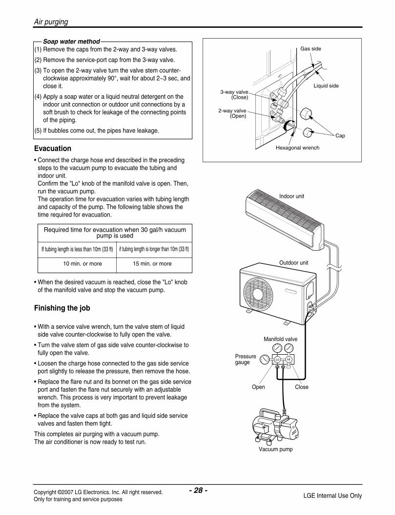
Evacuation• Connect the charge hose end described in the preceding
steps to the vacuum pump to evacuate the tubing andindoor unit.Confirm the "Lo" knob of the manifold valve is open. Then,run the vacuum pump.The operation time for evacuation varies with tubing lengthand capacity of the pump. The following table shows thetime required for evacuation.
• When the desired vacuum is reached, close the "Lo" knobof the manifold valve and stop the vacuum pump.
Finishing the job
• With a service valve wrench, turn the valve stem of liquidside valve counter-clockwise to fully open the valve.
• Turn the valve stem of gas side valve counter-clockwise tofully open the valve.
• Loosen the charge hose connected to the gas side serviceport slightly to release the pressure, then remove the hose.
• Replace the flare nut and its bonnet on the gas side serviceport and fasten the flare nut securely with an adjustablewrench. This process is very important to prevent leakagefrom the system.
• Replace the valve caps at both gas and liquid side servicevalves and fasten them tight.
This completes air purging with a vacuum pump. The air conditioner is now ready to test run.
(1) Remove the caps from the 2-way and 3-way valves.
(2) Remove the service-port cap from the 3-way valve.
(3) To open the 2-way valve turn the valve stem counter-clockwise approximately 90°, wait for about 2~3 sec, andclose it.
(4) Apply a soap water or a liquid neutral detergent on theindoor unit connection or outdoor unit connections by asoft brush to check for leakage of the connecting pointsof the piping.
(5) If bubbles come out, the pipes have leakage.
Soap water methodGas side
Liquid side
Cap
Hexagonal wrench
2-way valve(Open)
3-way valve(Close)
Required time for evacuation when 30 gal/h vacuumpump is used
10 min. or more 15 min. or more
If tubing length is less than 10m (33 ft) if tubing length is longer than 10m (33 ft)
Indoor unit
Outdoor unit
Lo Hi
Manifold valve
Vacuum pump
Pressure gauge
Open Close
Air purging

- 29 -Copyright ©2007 LG Electronics. Inc. All right reserved.Only for training and service purposes LGE Internal Use Only
Test running
Test Running1. Check that all tubing and wiring have been properly con-
nected.
2. Check that the gas and liquid side service valves are fullyopen.
Settlement of outdoor unit
• Anchor the outdoor unit with a bolt and nut(ø10mm) tightlyand horizontally on a concrete or rigid mount.
• When installing on the wall, roof or rooftop, anchor themounting base securely with a nail or wire assuming theinfluence of wind and earthquake.
• In the case when the vibration of the unit is conveyed to thehose, secure the unit with an anti-vibration bushing.
NOTE: If the actual pressure is higher than shown, the system ismost likely over-charged, and charge should be removed. If the actual pressure are lower than shown, the system ismost likely undercharged, and charge should be added.
The air conditioner is now ready for use.
Power-Failure Compensation Function User Selection ON/OFF
1) Operation Sequence
Press the forced switch until BUZZER sounds 2 times(beep~beep~).
Release the forced switch if BUZZER sounds.
Check the function selection ON/OFF with the operation LED.
2) Checking function-selection ON/OFF
- Function-Selection ON: One time blinking of operation LEDwould repeat 4 times.
- Function-Selection OFF: Two times blinking of operation LEDwould repeat 4 times.
Evaluation of the performanceOperate unit for 15~20 minutes, then check the systemrefrigerant charge:
1. Measure the pressure of the gas side service valve.
2. Measure the temperature of the intake and discharge of air.
3. Ensure the difference between the intake temperature andthe discharge is more than 8°C(46°F) (Cooling) or(Heating).
4. For reference; the gas side pressure of optimum conditionis as below.(Cooling)
Bolt
Tubing connection
Discharge temperature
Discharge air
Intake temperature
R-22 35°C (95°F) 4~5kg/cm2G(56.8~71.0 P.S.I.G.)R-410A 35°C (95°F) 8.5~9.5kg/cm2G(120~135 P.S.I.G.)
Outside ambientTEMP.Refrigerant The pressure of the gas side
service valve.
This is performed when the unit is to be relocated orthe refrigerant circuit is serviced.Pump Down means collecting all refrigerant in the outdoorunit without loss in refrigerant gas.
CAUTION:Be sure to perform Pump Down procedure with the unitcooling mode.
Pump Down Procedure1. Connect a low-pressure gauge manifold hose to the
charge port on the gas side service valve.
2. Open the gas side service valve halfway and purge the airfrom the manifold hose using the refrigerant gas.
3. Close the liquid side service valve(all the way in).
4. Turn on the unit's operating switch and start the coolingoperation.
5. When the low-pressure gauge reading becomes 1 to0.5kg/cm2 G(14.2 to 7.1 P.S.I.G.), fully close the gas sidevalve stem and then quickly turn off the unit. At that time,Pump Down has been completed and all refrigerant gaswill have been collected in the outdoor unit.
PUMP DOWN
Powerbutton

- 30 -Copyright ©2007 LG Electronics. Inc. All right reserved.Only for training and service purposes LGE Internal Use Only
Functions
• Room temperature sensor. (Thermistor)• Pipe temperature sensor. (Thermistor)
• Maintain the room temperature in accordance with the Setting Temp.
• Indoor fan is delayed for 5 sec at the starting.
• Restarting is for approx. 2 minutes.
• Super High, High, Med, Low
--- Lights up in operation
--- Lights up in Timer Mode or Sleep Mode
--- Lights up in Preheat Mode or Defrost Mode
--- Lights up in Plasma Air Clean Mode
--- Lights up in during Energy-Saving Cooling Mode Operation (Optional)
Indoor Unit
Operation ON/OFF by Remote controller
Sensing the Room Temperature
Room temperature control
Starting the Current Control
Time Delay Safety Control
Indoor Fan Speed Control
Operation indication Lamps (LED)
Cooling Mode Operation
Healty dehumidification Mode Operation
Heating Mode Operation
Jet Cool Mode Operation
Jet Heat Mode Operation
Energy Saving Cooling Mode Operation
Functions

- 31 -Copyright ©2007 LG Electronics. Inc. All right reserved.Only for training and service purposes LGE Internal Use Only
Functions
• Both the indoor and outdoor fan stops during defrosting.
Defrost(Deice) Control (Heating)
Hot-start Control (Heating)
Heater (Optional)
Plasma
Auto Clean(Optional)
Horizontal airflow Direction Control(Optional)
Energy-Saving Control(Optional)
Auto Changeover
• The fan is switched to S-Low(Cooling), low(Heating) speed.• The unit will be stopped after 1, 2, 3, 4, 5, 6, 7 hours.
• The fan is switched to intermittent or irregular operation• The fan speed is automatically switched from high to low speed.
• The louver can be set at the desired position or swing up and down automatically.
Sleep Mode Auto Control
Natural Air Control by CHAOS Logic
Airflow Direction Control
• The function will be operated while in any operation mode with selecting the function.• The function is to be stopped while it isoperating with selecting the function.
• The indoor fan stops until the evaporator pipe temperature will be reached at 30°C.
- 32 -Copyright ©2007 LG Electronics. Inc. All right reserved.Only for training and service purposes LGE Internal Use Only
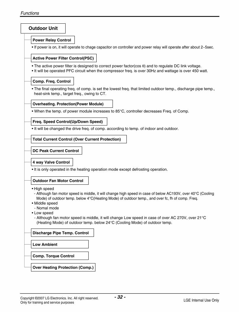
• If power is on, it will operate to chage capacitor on controller and power relay will operate after about 2~5sec.
• The active power filter is designed to correct power factor(cos θ) and to regulate DC link voltage.• It will be operated PFC circuit when the compressor freq. is over 30Hz and wattage is over 450 watt.
• The final operating freq. of comp. is set the lowest freq. that limited outdoor temp., discharge pipe temp.,heat-sink temp., target freq., owing to CT.
• It will be changed the drive freq. of comp. according to temp. of indoor and outdoor.
• It is only operated in the heating operation mode except defrosting operation.
• High speed- Although fan motor speed is middle, it will change high speed in case of below AC193V, over 40°C (Cooling
Mode) of outdoor temp. below 4°C(Heating Mode) of outdoor temp., and over fc, fh of comp. Freq.• Middle speed
- Nomal mode• Low speed
- Although fan motor speed is middle, it will change Low speed in case of over AC 270V, over 21°C(Heating Mode) of outdoor temp. below 24°C (Cooling Mode) of outdoor temp.
• When the temp. of power module increases to 85°C, controller decreases Freq. of Comp.
Outdoor Unit
Power Relay Control
Active Power Filter Control(PSC)
Comp. Freq. Control
OverheatIng. Protection(Power Module)
Freq. Speed Control(Up/Down Speed)
Total Current Control (Over Current Protection)
DC Peak Current Control
4 way Valve Control
Outdoor Fan Motor Control
Discharge Pipe Temp. Control
Low Ambient
Comp. Torque Control
Over Heating Protection (Comp.)
Functions

- 33 -Copyright ©2007 LG Electronics. Inc. All right reserved.Only for training and service purposes LGE Internal Use Only
Operation
Function of Controls
Operation
• DISPLAY1) C/O Model
Operation Indicator• ON while in appliance operation, OFF while in appliance pause.• Flashing while in disconnection or short in Thermistor. (3 sec off / 0.5 sec on)
Timer Indicator• ON while in timer mode (on/off), OFF when timer mode is completed or canceled.
Comp. Running Incidator• While in appliance operation, ON while in outdoor unit compressor running, OFF while in compressor off.
2) H/P Model
Operation Indicator• ON while in appliance operation, OFF while in appliance pause.• Flashing while in disconnection or short in Thermistor. (3 sec off / 0.5 sec on)
Timer Indicator• ON while in timer mode (on/off), OFF when timer mode is completed or canceled.
Defrost Indicator• OFF except when hot start during heating mode operation or while in defrost control.
• If the indoor pipe temperaure is below 0°C in 7 min. after the compressor operates without pause while incooling cycle operation mode, compressor, outdoor fan are turned off.
• When indoor pipe temp. is 7°C or higher after 2 min pause of compressor compressor, outdoor fan is turned on according to the condition of the room temperature.
Comp. free
Comp. Step 4Comp. Step 2
Comp. off0˚C3˚C6˚C 7˚C
Indoor pipetemp.
Protection of the evaporator pipe from frosting

- 34 -Copyright ©2007 LG Electronics. Inc. All right reserved.Only for training and service purposes LGE Internal Use Only
Cooling mode operation
• Operating frequency of compressor depend on the difference of the temperature.(= intake air Temp.- Compressor off Temp.
• Compressor off temp.= setting temp. -0.5°Con temp. = setting temp. +0.5°C
• If compressor operates at some operating frequency, the operating frequency of compressor cannot bechanged within 30 seconds.
• Condition of compressor turned off- When intake air temperature stay at the temperature between setting temp. -0.5°C and setting temp. -1.0°C for 3 minutes continuously.
- When intake air temperature reaches below the temperature of setting temp. -1.0°C.• Compressor 2 minutes delay
- The compressor can restart minimum 2 minutes later after compressor off.
Temp. differences Comp. Operating frequencyover 2.5°C Step 72.0~2.49°C Step 61.5~1.99°C Step 51.0~1.49°C Step 40.5~0.99°C Step 30.0~0.49°C Step 2-0.5~0°C Step 1
[The operating freq. step of comp.]
[The targeting operating freq. of comp. each model]
Model
AS-W0964DH0/DH1/GH0 35 39 43 47 52 57 62AS-W1264DH0/GH0 20 35 47 56 63 70 78
AS-W1865DH0 16 32 58 64 70 75 85AS-W1224DH0 20 35 47 54 65 70 74AS-W1424DH0 20 35 47 54 72 74 78AS-W1825DH0 16 32 53 62 72 75 85AS-W096E1G0 25 35 40 52 56 74 82AS-W126E1G0 25 35 40 52 66 74 82
Comp. Operating frequencyStep 1 Step 2 Step 3 Step 4 Step 5(Fc) Step 6 Step 7
Healthy Dehumidification mode operation• When the dehumidification operation is set by the remote controller the intake air temperature is detected and
the setting temp. is automatically set according to the intake air temperature.
• When intake air temp reaches above the temp of setting +1.0°C, condition of compressor same as coolingmode operation.
• When intake air temperature reaches bolow the temp of setting –1.0°C, compressor operate step1~step3 andindoor fan speed repeatly operate low or stop.
Intake air Temp.
26°C ≤ intake air temp.
24°C ≤ intake air temp.< 26°C
18°C < intake air temp. < 24°C
intake air temp. ≤ 18°C
Setting Temp.
25°C
intake air temp. -1°C
intake air temp. -0.5°C
18°C
Operation

- 35 -Copyright ©2007 LG Electronics. Inc. All right reserved.Only for training and service purposes LGE Internal Use Only
Operation
• Operating frequency of compressor depend on the difference of the temperature(= compressor off temp. - intake air temp.)
• Compressor off temp. = setting temp. +4°Con temp. = setting temp. +2°C
• If compressor operates at some operation frequency, the operating frequency of compressor cannot bechanged within 30 seconds.
• Condition of compressor turned off- When intake air temperature reaches +4°C above the setting temperature.
• Condition of indoor fan turned off- While in compressor on:indoor pipe temp. < 20°C
• While in defrost control, between the indoor and outdoor fans are turned off.• Compressor 2minutes delay
- After compressor off, the compressor can restart minimum 2 minutes later.
Temp. differences
2.5~3.0°C
2.0~2.49°C
1.5~1.99°C
1.0~1.49°C
0.5~0.99°C
0.0~0.49°C
-0.5~0°C
Comp. Operating frequency
Step 1
Step 2
Step 3
Step 4
Step 5
Step 6
Step 7
[ The operating freq. step of comp]
[The targeting operating freq. of comp. each model]
Heating mode operation
Model
AS-W0964DH0/DH1/GH0 35 44 53 62 69 74 80
AS-W1264DH0/GH0 20 38 53 63 72 79 86
AS-W1865DH0 16 38 47 65 79 87 96
AS-W1224DH0 20 35 53 63 70 79 86
AS-W1424DH0 20 35 53 63 77 79 86
AS-W1825DH0 16 38 47 62 79 87 90
AS-W096E1G0 35 40 48 56 65 90 94
AS-W126E1G0 35 40 48 56 80 90 94
Comp. Operating frequencyStep 1 Step 2 Step 3 Step 4 Step 5 Step 6 Step 7
• While in heating mode or Fuzzy operation, the Jet Cool key cannot be input. When it is input while in theother mode operation(cooling, dehumidification, ventilation), the Jet Cool mode is operated.
• In the Jet Cool mode, the indoor fan is operated super-high speed for 30 min. at cooling mode operation.• In the Jet Cool mode, the room temperature is controlled to the setting temperature, 18°C.• When the sleep timer mode input while the Jet Cool mode operation, the Jet Cool mode has the priority.• When the Jet Cool key is input, the upper/lower vane is reset to those of the initial cooling mode and then
operated in order that the air outflow could reach further.
Jet cool mode operation

- 36 -Copyright ©2007 LG Electronics. Inc. All right reserved.Only for training and service purposes LGE Internal Use Only
• While in cooling mode or Fuzzy operation, the Jet Heat key cannot be input. When it is input while in theHeating mode operation (dehumidification), the Jet Heat mode is operated.
• In the Jet Heat mode, the indoor fan is operated super-high speed for 60 min. at Heating mode operation.• In the Jet Heat mode, the room temperature is controlled to the setting temperature, 30°C.• When the sleep timer mode input while the Jet Heat mode operation, the Jet Heat mode has the priority.• When the Jet Heat key is input, the upper/lower vane is reset to those of the initial Jet heating mode and
then operated in order that the air outflow could reach under flow.
1. New Chaos swing mode• By the Chaos swing key input, the upper/lower vane automatically operates with the Chaos swing or it is
fixed to the desired direction.
Mode2
Mode3
Mode4
Mode5
Mode6
Mode7
Mode8
Mode9
OPEN
CLOSED
8°
Cooling Operation
120°
Mode2
Mode3
Mode4
Mode5
Mode6
Mode7
Mode8
Mode9
OPEN
CLOSED
8°
Heating Operation
120°
Mode1
Mode1
Mode2
Mode3
Mode4
Mode5
Mode6
Mode7
Mode8
OPEN
CLOSED
8°
Cooling Operation
Mode1
Mode2
Mode3
Mode4
Mode5
Mode6
Mode7
Mode8
OPEN
CLOSED
8°
Heating Operation
110°110°
Start
(S4, SE) 7, 9, 12, 14k Model
Start
Start
Start
(S5) 18, 24k Model
Jet heat mode operation
Swing mode
Operation

- 37 -Copyright ©2007 LG Electronics. Inc. All right reserved.Only for training and service purposes LGE Internal Use Only
Operation
1. Sleep timer operation for cooling cycle• While in cooling mode operation, 30 min. later since the start of the sleep timer, the setting temperature
increase by 1°C. After another 30min. elapse, it increases by 1°C again.
2. Sleep timer operation for heating cycle• While in heating mode operation, 60 min. later since the start of the sleep timer, the setting temperature
decrease by 1°C. After another 60min. elapse, it decreases by 1°C again.
Setting temp. (˚C)
1.0˚C up
1.0˚C up
Cooling ON temp.(Setting temp. +0.5˚C)
Cooling OFF temp.(Setting temp. -0.5˚C)
0.5 1 Sleep time (hr)
Setting temp. (°C)
Heating ON temp.(Setting temp. +2°C)
Heating OFF temp.(Setting temp. +4°C)
1 2 Sleep time (hr)
1.0°C down
1.0°C down
• When the sleep time is reached after [1,2,3,4,5,6,7hr] is input by the remote control during the operation, theoperation of the appliance stops.
• When the appliance is on pause, the sleep timer mode cannot be input.
Sleep timer operation
- 38 -Copyright ©2007 LG Electronics. Inc. All right reserved.Only for training and service purposes LGE Internal Use Only
Auto restarting operation
Forced operation
Test Operation
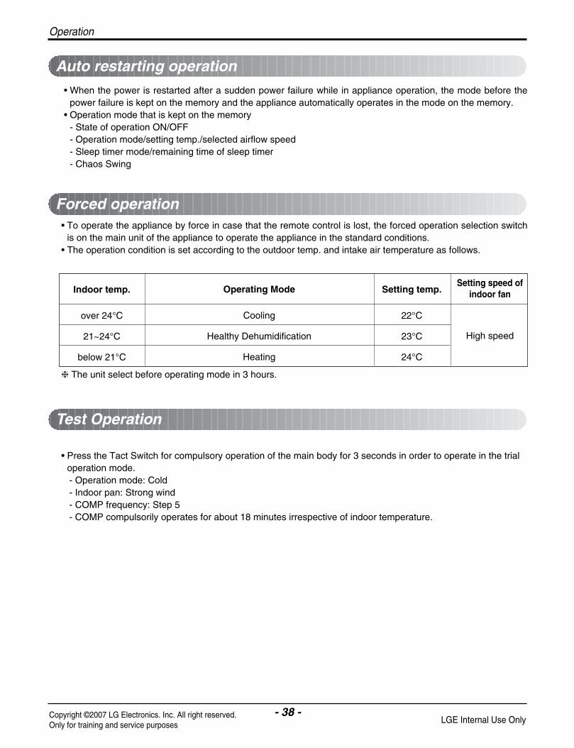
• When the power is restarted after a sudden power failure while in appliance operation, the mode before thepower failure is kept on the memory and the appliance automatically operates in the mode on the memory.
• Operation mode that is kept on the memory- State of operation ON/OFF- Operation mode/setting temp./selected airflow speed- Sleep timer mode/remaining time of sleep timer- Chaos Swing
• To operate the appliance by force in case that the remote control is lost, the forced operation selection switchis on the main unit of the appliance to operate the appliance in the standard conditions.
• The operation condition is set according to the outdoor temp. and intake air temperature as follows.
The unit select before operating mode in 3 hours.
• Press the Tact Switch for compulsory operation of the main body for 3 seconds in order to operate in the trialoperation mode. - Operation mode: Cold- Indoor pan: Strong wind- COMP frequency: Step 5- COMP compulsorily operates for about 18 minutes irrespective of indoor temperature.
Indoor temp.
over 24°C
21~24°C
below 21°C
Setting temp.
22°C
23°C
24°C
Setting speed ofindoor fan
High speed
Operating Mode
Cooling
Healthy Dehumidification
Heating
Operation

- 39 -Copyright ©2007 LG Electronics. Inc. All right reserved.Only for training and service purposes LGE Internal Use Only
Operation
• Power relay turns on 1 second later after the power is input to the outdoor unit.• Control sequence : power on PTC operating power relay on
CT1 control• If the operating current reaches I1, the operating frequency of the compressor decrease.• After decreasing the operating frequency by 1step, if operating current is below I1 for 60 seconds continuous-
ly, the operating frequency of compressor increase by 1step.
CT2 control• If the operating current of the appliance reaches I2, the compressor stop instantly and 2 minutes later the
compressor restart again.• If CT2 occurs 5 times within 1hour, the appliance turn off and display ERROR CODE 7.
I1:Current of operating frequency downI2: Current of compressor cut off
cf. I1 is set the lowest level between intial value and in case dectection of dc paeak current.
Control table
DC Peak Current Error by a fault signal of IPM• If the operating current of IPM reaches 35A ±3A, the compressor stop instantly.• If DC PEAK occurs 5 times within 1 hour, the appliance turns off and display ERROR CODE 6.
DC Peak Current Error by the compressor lock• If the DC LINK voltage below DC 140V occurs 5 times within 1 hour while the compressor is operating, the
appliance turns off and display ERROR CODE 6.
DC Peak Current Error by the Outdoor Fan Lock• If it’s 5 times within 1 hour in case of the temperature of outdoor pipe TH is over 65°C while the compressor is
operating, the appliance turns off and display ERROR CODE 6.
Power relay control
Protection from total current control
Protection from DC Peak Current
1 AS-W096DH0/DH1/GH0 5.5 6.5 6 7 9
2 AS-W126DH0/GH0 6.5 7.5 7 8 10
3 AS-W1865DH0 9 10.5 9.5 11 13
4 AS-W1224DH0 6 6.5 6.5 7 8.5
5 AS-W1424DH0 6 6.5 6.5 7 9
6 AS-W1825DH0 10.5 11.5 11 12 14
7 AS-W096E1G0 7 8.5 7.5 9 10
8 AS-W126E1G0 7 8.5 7.5 9 10
I1
Cooling Heating Cooling HeatingOutdoor temp ≥ 38°C Outdoor temp < 38°C I2Model
- 40 -Copyright ©2007 LG Electronics. Inc. All right reserved.Only for training and service purposes LGE Internal Use Only
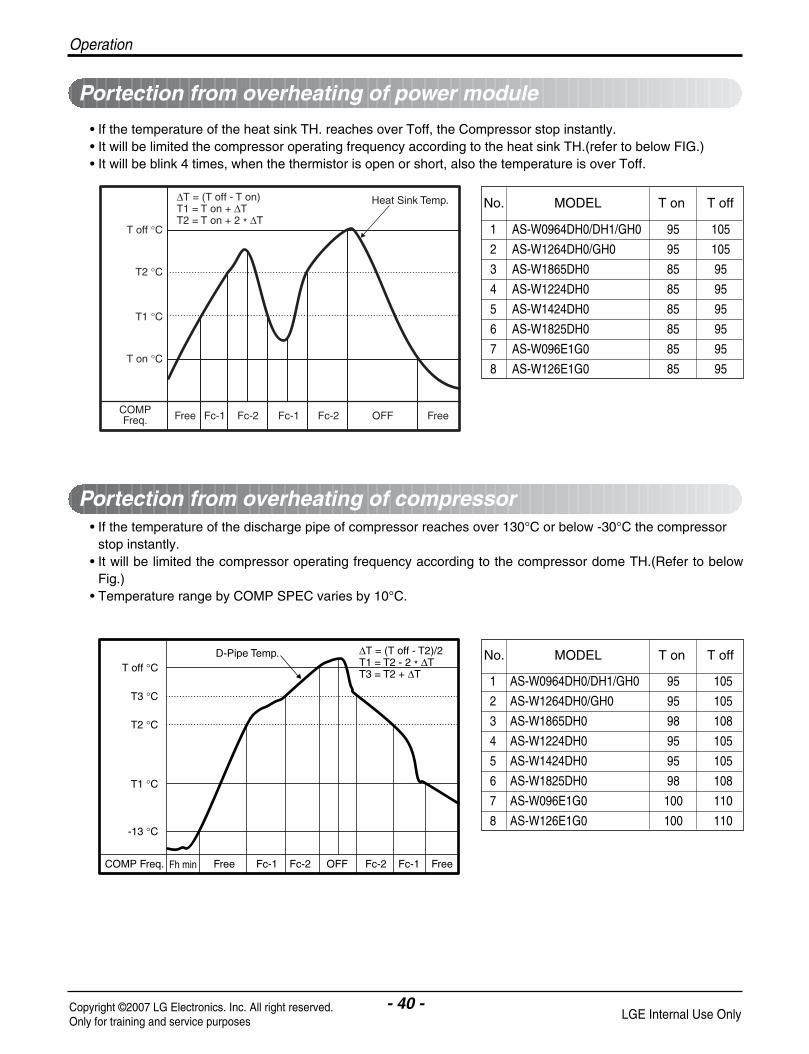
• If the temperature of the heat sink TH. reaches over Toff, the Compressor stop instantly.• It will be limited the compressor operating frequency according to the heat sink TH.(refer to below FIG.)• It will be blink 4 times, when the thermistor is open or short, also the temperature is over Toff.
• If the temperature of the discharge pipe of compressor reaches over 130°C or below -30°C the compressorstop instantly.
• It will be limited the compressor operating frequency according to the compressor dome TH.(Refer to belowFig.)
• Temperature range by COMP SPEC varies by 10°C.
Portection from overheating of power module
Portection from overheating of compressor
T off °C
T2 °C
Heat Sink Temp.
T1 °C
T on °C
COMPFreq. Free OFF FreeFc-1 Fc-1Fc-2 Fc-2
∆T = (T off - T on)T1 = T on + ∆TT2 = T on + 2 * ∆T
D-Pipe Temp.
COMP Freq. Free FreeFh min OFFFc-1 Fc-1Fc-2 Fc-2
∆T = (T off - T2)/2T1 = T2 - 2 * ∆TT3 = T2 + ∆T
T off °C
T2 °C
T3 °C
T1 °C
-13 °C
1 AS-W0964DH0/DH1/GH0 95 105
2 AS-W1264DH0/GH0 95 105
3 AS-W1865DH0 85 95
4 AS-W1224DH0 85 95
5 AS-W1424DH0 85 95
6 AS-W1825DH0 85 95
7 AS-W096E1G0 85 95
8 AS-W126E1G0 85 95
No. MODEL T on T off
1 AS-W0964DH0/DH1/GH0 95 105
2 AS-W1264DH0/GH0 95 105
3 AS-W1865DH0 98 108
4 AS-W1224DH0 95 105
5 AS-W1424DH0 95 105
6 AS-W1825DH0 98 108
7 AS-W096E1G0 100 110
8 AS-W126E1G0 100 110
No. MODEL T on T off
Operation

- 41 -Copyright ©2007 LG Electronics. Inc. All right reserved.Only for training and service purposes LGE Internal Use Only
Operation
• While in heating mode operation in order to protect the evaporator pipe of the outdoor unit from freezing,reversed to cooling cycle to defrost the evaporator pipe of the outdoor unit.
• Defrosting control is available 50 minutes later since heating cycle started and the pipe temperature of out-door unit reaches below -6°C.
Setting Freq.OperatingFreq. of Comp.
4-Way
EEVOpen step
OutdoorFAN
Indoor FAN
Pre-Heat LED
Deice STEP
Fhmin
Minimum Timeof Heating
Main Deice time
Fhmin
Fhmin
ON
OFF Setting Speed
ON
HotStartOFF
HotStarting
ONOFF OFF
0 1 2 3 4 5 6
SettingStarting step
Setting Freq.
Setting Speed
Setting Speed
Hi Speed
Defrosting control

- 42 -Copyright ©2007 LG Electronics. Inc. All right reserved.Only for training and service purposes LGE Internal Use Only
• Function used to perform the Self Cleaning to prevent the Unit from Fungus and Bad Odors.• Used after the Shut Down of Cooling Operation to Clean the Evaporator and keep it as fresh for the Next operation.• During Self Cleaning the Outdoor Unit is Switched off.• The function is easy to be operated as It is accessed through the Remote Controller.
Auto Cleaning
Auto Changeover
Low Ambient
Comp. ONOFF
Setting Step LowIndoor Fan
ON
2) Cooling/only Model
Cooling CYCLE
OFF
30 Min
Fan
ON
1) Heat/pump Model
Cooling CYCLE
OFF
Comp. ONONOFF OFF
Indoor Fan Setting Step Low Low Low
13 Min
HeatingFan
60 Sec 120 Sec
Fan
• The air conditioner changes the operationmode automatically to keep indoor tempera-ture.
• When room temperature vary over ±2°C withrespect to setting temperature, air condition-er keeps the room temperature in ±2°C withrespect to setting temperature by autochange mode.
• If outdoor temperature drops below certain temperature,liquid back is prevented by reducing fan speed.It can prevent frosting of evaporator and keep cooling operation
• No matter even if the outdoor temperature reaches -10°C.• You can Cool your room at your desired temperature all your around.
Freq.
- 0°C °… Outdoor temp.
Outdoor pipe temp.0°C outdoor fan On/Offcontrol
°
Comp Freq.
Outdoor fan
On On
OffOff
Outdoor temp.:-10°C
-5
0
5
10
15
20
25
0 50 100 150 200
Time(Min.)
Tem
p.(°
C)
Outdoor fan On/Off control
Cond . temp.
COOLINGAutoChangeMode.
Outdoor temp.Indoor temp.
Outdoortemp.
30°C
20°C
10°C
+2°C+1°C
+0.5°CSet Temp.-0.5°C-1°C-2°C
HEATING
Operation

- 43 -Copyright ©2007 LG Electronics. Inc. All right reserved.Only for training and service purposes LGE Internal Use Only
Operation
Remote Control OperationsThe controls will look like the following.
1. START/STOP BUTTONOperation starts when this button is pressed and stops when the button is pressed again.
2. OPERATION MODE SELECTION BUTTONUsed to select the operation mode.
3. ROOM TEMPERATURE SETTING BUTTONSUsed to select the room temperature.
4. INDOOR FAN SPEED SELECTORUsed to select fan speed in four stepslow, medium, high and CHAOS.
5. JET COOL/JET HEATUsed to start or stop the speed cooling/heating.(speed cooling/heating operates super high fan speed incooling/heating mode.)
6. CHAOS SWING BUTTONUsed to stop or start louver movement and set the desired up/down airflow direction.
7. ON/OFF TIMER BUTTONSUsed to set the time of starting and stopping operation.
8. TIME SETTING BUTTONSUsed to adjust the time.
9. TIMER SET/CANCEL BUTTONUsed to set the timer when the desired time is obtainedand to cancel the Timer operation.
10. SLEEP MODE AUTO BUTTONUsed to set Sleep Mode Auto operation.
11. ENERGY-SAVING COOLING MODE BUTTON(OPTIONAL)Used to set Energy-Save in cooling mode.
12. ROOM TEMPERATURE CHECKING BUTTONUsed to check the room temperature.
13. PLASMA(OPTIONAL)Used to start or stop the plasma function.
14. HORIZONTAL AIRFLOW DIRECTION CONTROLBUTTON (OPTIONAL)Used to set the desired horizontal airflow direction.
15. RESET BUTTONUsed prior to resetting time.
16. 2ND F BUTTONUsed prior to using modes printed in blue at the bottom ofbuttons.
17. AUTO CLEAN (OPTIONAL)Used to set Auto Clean mode.
ON OFF
CANCEL
AUTO CLEANSET
1
3
5
4
9
10
12
1416
72
813
15
11
6
Cooling Operation
Auto Operation or Auto Changeover
Healthy Dehumidification Operation
Flip-up door(opened)
Heating Operation
Signal transmitter
• Cooling Model( ), Heat Pump Model( )
17
Operation Mode
- 44 -Copyright ©2007 LG Electronics. Inc. All right reserved.Only for training and service purposes LGE Internal Use Only
DisassemblyIndoor Unit
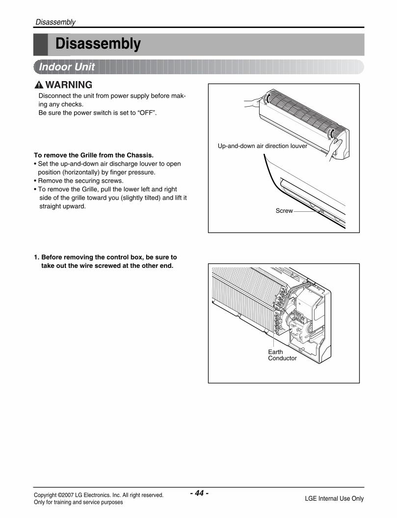
Disconnect the unit from power supply before mak-ing any checks.Be sure the power switch is set to “OFF”.
To remove the Grille from the Chassis. • Set the up-and-down air discharge louver to open
position (horizontally) by finger pressure.• Remove the securing screws.• To remove the Grille, pull the lower left and right
side of the grille toward you (slightly tilted) and lift itstraight upward.
1. Before removing the control box, be sure totake out the wire screwed at the other end.
EarthConductor
Disassembly
- 45 -Copyright ©2007 LG Electronics. Inc. All right reserved.Only for training and service purposes LGE Internal Use Only
Disassembly
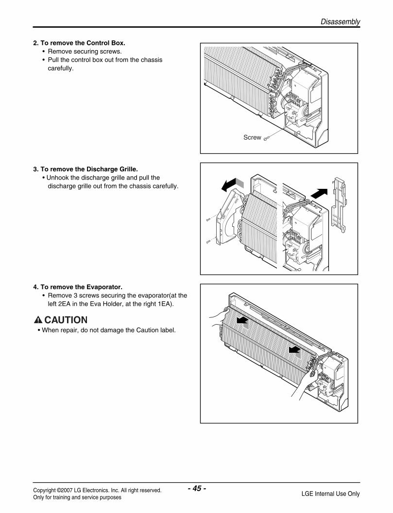
2. To remove the Control Box.• Remove securing screws. • Pull the control box out from the chassis
carefully.
3. To remove the Discharge Grille.• Unhook the discharge grille and pull the
discharge grille out from the chassis carefully.
4. To remove the Evaporator. • Remove 3 screws securing the evaporator(at the
left 2EA in the Eva Holder, at the right 1EA).
Screw
• When repair, do not damage the Caution label.

- 46 -Copyright ©2007 LG Electronics. Inc. All right reserved.Only for training and service purposes LGE Internal Use Only
• Unhook the tab on the right inside of the chassisat the same time, slightly pull the evaporatortoward you until the tab is clear of the slot.
5. To remove the Motor Cover• Remove 2 securing screw.• Pull the motor cover out from the chassis
carefully.
6. To remove the Cross-Flow Fan• Loosen the screw securing the cross-flow fan to
the fan motor (do not remove).• Lift up the right side of the cross-flow fan and the
fan motor, separate the fan motor from thecross-flow fan.
• Remove the left end of the cross-flow fan fromthe self-aligning bearing.
Motor cover
Bearing
Cross-flow fan
Disassembly

- 47 -Copyright ©2007 LG Electronics. Inc. All right reserved.Only for training and service purposes LGE Internal Use Only
Troubleshooting Guide
Troubleshooting Guide
INDOOR UNIT OUTDOOR UNIT
HEATEXCHANGE(EVAPORATOR)
HEATEXCHANGE(CONDENSER)
EEV
COMPRESSOR
ACCUMULATOR
GAS SIDE
3-WAY VALVE
LIQUID SIDE
3-WAY VALVE
COOLING
HEATING
REVERSINGVALVE
INDOOR UNIT OUTDOOR UNIT
HEATEXCHANGE(EVAPORATOR)
HEATEXCHANGE(CONDENSER)
COMPRESSOR
ACCUMULATOR
GAS SIDE
3-WAY VALVE
LIQUID SIDE
3-WAY VALVE
COOLING
HEATING
REVERSINGVALVE
(1) Model Capillary Tube
Refrigeration Cycle Diagram
(2) Model Adopted Electronic Expansion Valve
Troubleshooting Guide
- 48 -Copyright ©2007 LG Electronics. Inc. All right reserved.Only for training and service purposes LGE Internal Use Only
2-way, 3-way Valve
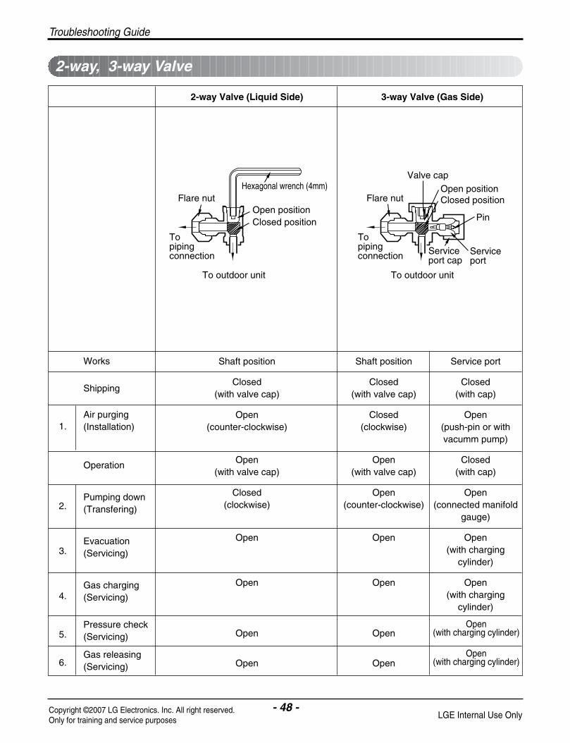
2-way Valve (Liquid Side) 3-way Valve (Gas Side)
Shaft position Shaft position Service port
Closed Closed Closed(with valve cap) (with valve cap) (with cap)
Open Closed Open(counter-clockwise) (clockwise) (push-pin or with
vacumm pump)
Open Open Closed(with valve cap) (with valve cap) (with cap)
Closed Open Open(clockwise) (counter-clockwise) (connected manifold
gauge)
Open Open Open(with charging
cylinder)
Open Open Open(with charging
cylinder)
Open Open
Open Open
Works
Shipping
Air purging(Installation)
Operation
Pumping down(Transfering)
Evacuation(Servicing)
Gas charging(Servicing)
Pressure check(Servicing)
Gas releasing(Servicing)
1.
2.
3.
4.
5.
6.
Valve cap
Open positionClosed position
Pin
Serviceport
Serviceport cap
To outdoor unit
Flare nut
To piping connection
To outdoor unit
Hexagonal wrench (4mm)
Open positionClosed position
To piping connection
Flare nut
Open(with charging cylinder)
Open(with charging cylinder)

- 49 -Copyright ©2007 LG Electronics. Inc. All right reserved.Only for training and service purposes LGE Internal Use Only
Troubleshooting Guide
Required tools : hexagonal wrench, adjustable wrench,torque wrenches, wrench to hold thejoints, and gas leak detector.
The additional gas for air purging has been chargedin the outdoor unit.However, if the flare connections have not be donecorrectly and there gas leaks, a gas cylinder and thecharge set will be needed.
The air in the indoor unit and in the piping must bepurged. If air remains in the refrigeration pipes, it willaffect the compressor, reduce to cooling capacity,and could lead to a malfunction.
• Procedure
(1) Recheck the piping connections.
(2) Open the valve stem of the 2-way valve coun-terclockwise approximately 90°, wait 10 sec-onds, and then set it to closed position. – Be sure to use a hexagonal wrench to operate
the valve stem.
(3) Check for gas leakage.– Check the flare connections for gas leakage.
(4) Purge the air from the system. – Set the 2-way valve to the open position and
remove the cap from the 3-way valve’s serviceport.
– Using the hexagonal wrench to press the valvecore pin, discharge for three seconds and thenwait for one minute. Repeat this three times.
(5) Use torque wrench to tighten the service portnut to a torque of 1.8kg.cm.
(6) Set the 3-way valve to the back seat.
(7) Mount the valve stem nuts to the 2-way and 3-way valves.
(8) Check for gas leakage. – At this time, especially check for gas leakage
from the 2-way and 3-way valve’s stem nuts,and from the service port nut.
Service port nut:Be sure, using a torque wrench to tighten the service port nut (after using the service port), so that it prevents thegas leakage from the refrigeration cycle.
CAUTION: Do not leak the gas in the air during Air purging.
CAUTION: If gas leakage are discoveredin step (3) above, take the followingmesures :
If the gas leaks stop when the piping connectionsare tightened further, continue working from step (4). If the gas leaks do not stop when the connectionsare retightened, repair the location of the leak, dis-charge all of the gas through the service port, andthen recharge with the specified amount of gas froma gas cylinder.
Liquid side
Outdoor unit
3-wayvalve
Gas side
Indoor unit
2-wayvalve
Open
Clsed
Air purging
Troubleshooting Guide
- 50 -Copyright ©2007 LG Electronics. Inc. All right reserved.Only for training and service purposes LGE Internal Use Only
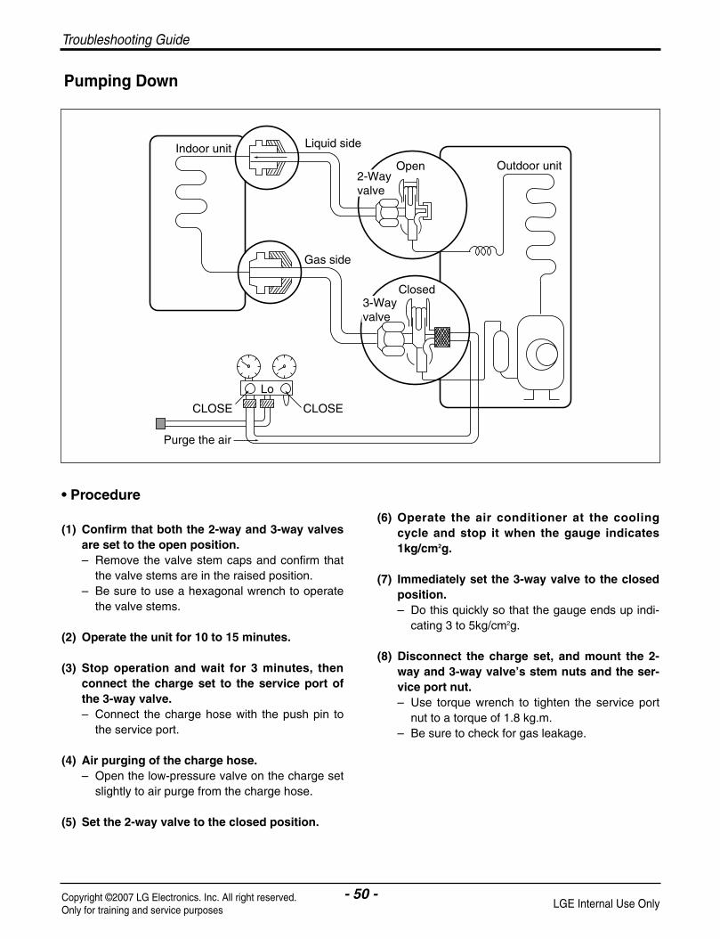
• Procedure
(1) Confirm that both the 2-way and 3-way valvesare set to the open position. – Remove the valve stem caps and confirm that
the valve stems are in the raised position. – Be sure to use a hexagonal wrench to operate
the valve stems.
(2) Operate the unit for 10 to 15 minutes.
(3) Stop operation and wait for 3 minutes, thenconnect the charge set to the service port ofthe 3-way valve.– Connect the charge hose with the push pin to
the service port.
(4) Air purging of the charge hose.– Open the low-pressure valve on the charge set
slightly to air purge from the charge hose.
(5) Set the 2-way valve to the closed position.
(6) Operate the air conditioner at the coolingcycle and stop it when the gauge indicates1kg/cm2g.
(7) Immediately set the 3-way valve to the closedposition.– Do this quickly so that the gauge ends up indi-
cating 3 to 5kg/cm2g.
(8) Disconnect the charge set, and mount the 2-way and 3-way valve’s stem nuts and the ser-vice port nut. – Use torque wrench to tighten the service port
nut to a torque of 1.8 kg.m. – Be sure to check for gas leakage.
Lo
Closed
Purge the air
Outdoor unit
Indoor unit Liquid side
Gas side
CLOSE
Open2-Wayvalve
3-Wayvalve
CLOSE
Pumping Down

- 51 -Copyright ©2007 LG Electronics. Inc. All right reserved.Only for training and service purposes LGE Internal Use Only
Troubleshooting Guide
Re-air Purging
(Re-installation)
• Procedure
(1) Confirm that both the liquid side valve and thegas side valve are set to the closed position.
(2) Connect the charge set and a gas cylinder tothe service port of the Gas side valve. – Leave the valve on the gas cylinder closed.
(3) Air purging. – Open the valves on the gas cylinder and the
charge set. Purge the air by loosening the flarenut on the liquid side valve approximately 45°for 3 seconds then closing it for 1 minute;repeat 3 times.
– After purging the air, use a torque wrench totighten the flare nut on liquid side valve.
(4) Check for gas leakage.– Check the flare connections for gas leakage.
(5) Discharge the refrigerant. – Close the valve on the gas cylinder and dis-
charge the refrigerant until the gauge indicates3 to 5 kg/cm2g.
(6) Disconnect the charge set and the gas cylin-der, and set the Liquid side and Gas sidevalves to the open position.– Be sure to use a hexagonal wrench to operate
the valve stems.
(7) Mount the valve stem nuts and the serviceport nut.– Use torque wrench to tighten the service port
nut to a torque of 1.8 kg.m.– Be sure to check for gas leakage.
CAUTION: Do not leak the gas in the airduring Air Purging.
Lo
Closed
OPEN
Closed
Gas cylinder
R22
Outdoor unit
Indoor unit Liquid side
Gas side
CLOSE
3-Wayvalve
3-Wayvalve
Troubleshooting Guide
- 52 -Copyright ©2007 LG Electronics. Inc. All right reserved.Only for training and service purposes LGE Internal Use Only
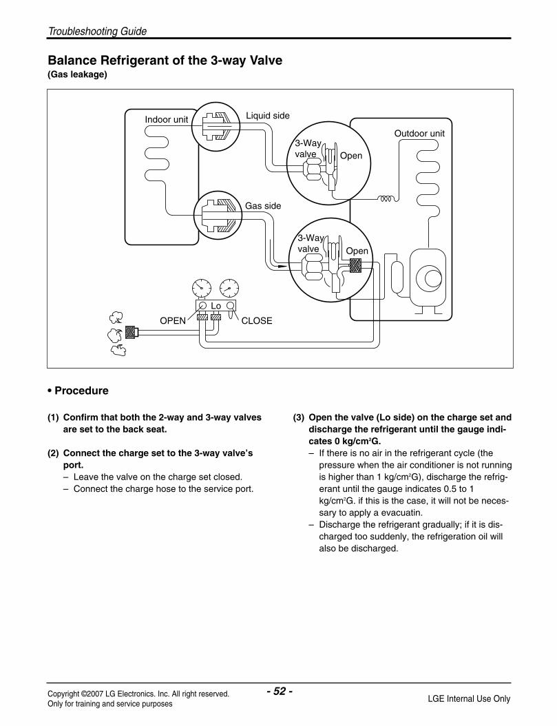
Balance Refrigerant of the 3-way Valve(Gas leakage)
• Procedure
(1) Confirm that both the 2-way and 3-way valvesare set to the back seat.
(2) Connect the charge set to the 3-way valve’sport. – Leave the valve on the charge set closed. – Connect the charge hose to the service port.
(3) Open the valve (Lo side) on the charge set anddischarge the refrigerant until the gauge indi-cates 0 kg/cm2G.– If there is no air in the refrigerant cycle (the
pressure when the air conditioner is not runningis higher than 1 kg/cm2G), discharge the refrig-erant until the gauge indicates 0.5 to 1kg/cm2G. if this is the case, it will not be neces-sary to apply a evacuatin.
– Discharge the refrigerant gradually; if it is dis-charged too suddenly, the refrigeration oil willalso be discharged.
Lo
Open
Open3-Wayvalve
3-Wayvalve
Gas side
CLOSEOPEN
Outdoor unit
Liquid sideIndoor unit
- 53 -Copyright ©2007 LG Electronics. Inc. All right reserved.Only for training and service purposes LGE Internal Use Only
Troubleshooting Guide
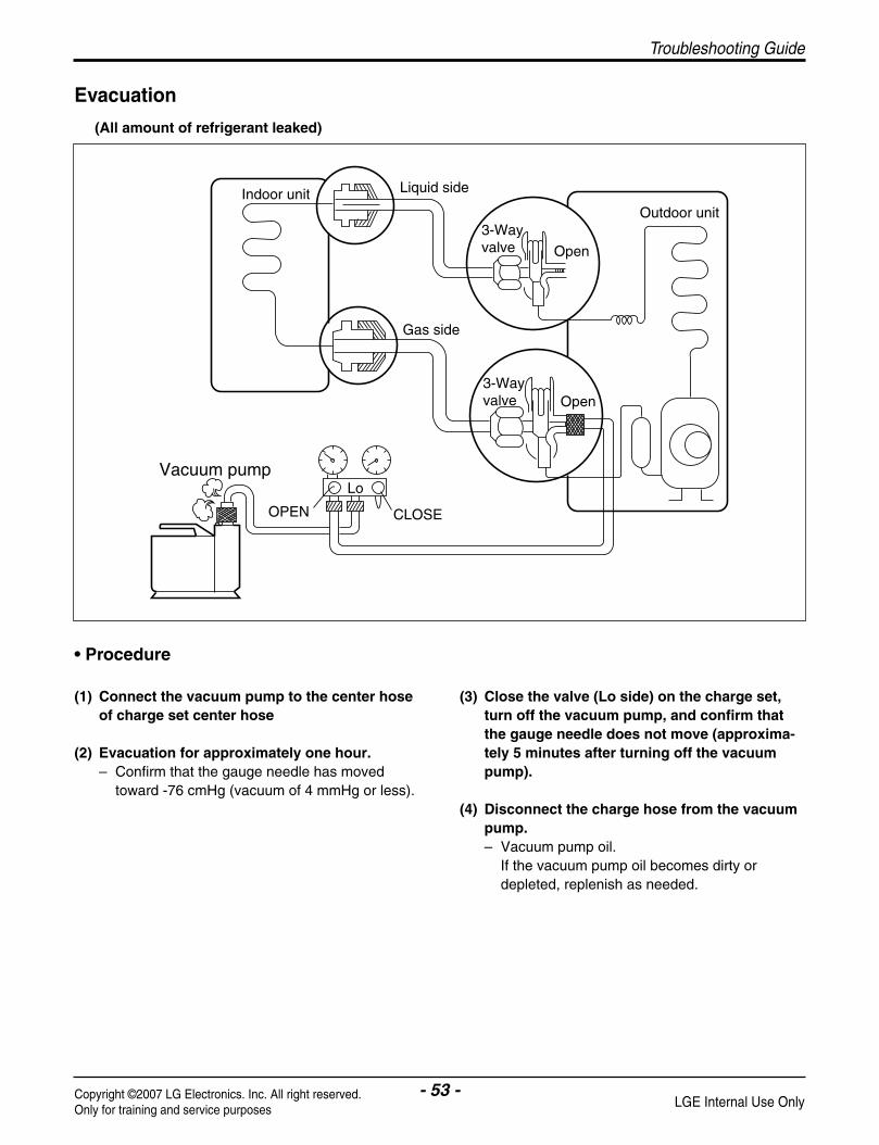
Evacuation
(All amount of refrigerant leaked)
• Procedure
(1) Connect the vacuum pump to the center hoseof charge set center hose
(2) Evacuation for approximately one hour. – Confirm that the gauge needle has moved
toward -76 cmHg (vacuum of 4 mmHg or less).
(3) Close the valve (Lo side) on the charge set,turn off the vacuum pump, and confirm thatthe gauge needle does not move (approxima-tely 5 minutes after turning off the vacuumpump).
(4) Disconnect the charge hose from the vacuumpump. – Vacuum pump oil.
If the vacuum pump oil becomes dirty ordepleted, replenish as needed.
Lo
Open
Open
Vacuum pump
3-Wayvalve
Outdoor unit
Liquid sideIndoor unit
Gas side
3-Wayvalve
CLOSEOPEN

Troubleshooting Guide
- 54 -Copyright ©2007 LG Electronics. Inc. All right reserved.Only for training and service purposes LGE Internal Use Only
Gas Charging
(After Evacuation)
• Procedure
(1) Connect the charge hose to the chargingcylinder. – Connect the charge hose which you dis-con-
nected from the vacuum pump to the valve atthe bottom of the cylinder.
– If you are using a gas cylinder, also use ascale and reverse the cylinder so that the sys-tem can be charged with liquid.
(2) Purge the air from the charge hose. – Open the valve at the bottom of the cylinder
and press the check valve on the charge set topurge the air. (Be careful of the liquid refriger-ant). The procedure is the same if using a gascylinder.
(3) Open the valve (Lo side on the charge set andcharge the system with liquid refrigerant.– If the system can not be charged with the spec-
ified amount of refrigerant, it can be chargedwith a little at a time (approximately 150g eachtime) while operating the air conditioner in thecooling cycle; however, one time is not suffi-cient, wait approximately 1 minute and thenrepeat the procedure (pumping down-pin).
(4) Immediately disconnect the charge hose fromthe 3-way valve’s service port. – Stopping partway will allow the gas to be dis-
charged.– If the system has been charged with liquid
refrigerant while operating the air conditionerturn off the air conditioner before disconnectingthe hose.
(5) Mount the valve stem nuts and the serviceport nut. – Use torque wrench to tighten the service port
nut to a torque of 1.8 kg.m.– Be sure to check for gas leakage.
\
This is different from previous procedures.Because you are charging with liquid refrigerantfrom the gas side, absolutely do not attempt tocharge with larger amounts of liquid refrigerantwhile operating the air conditioner.
Lo
Chargingcylinder
Outdoor unit
Indoor unit Liquid side
Gas side
CLOSE
Open3-Wayvalve
3-Wayvalve
OPEN
Open
Check valve
(1)

- 55 -Copyright ©2007 LG Electronics. Inc. All right reserved.Only for training and service purposes LGE Internal Use Only
Troubleshooting Guide
Trouble analysis
1. Check temperature difference between intake and discharge air and operating current.
Temp. Difference
Temp. difference : approx. 0°CCurrent : less than 80% of
rated current
Temp. difference : approx. 8°CCurrent : less than 80% of
rated current
Temp. difference : less than 8°CCurrent : over the reated
current
Temp. difference : over 8°C
Operating Current
• All amount of refrigerant leakedout. Check refrigeration cycle.
• Refrigerant leakegeClog of refrigeration cycleDefective compressor
• Excessive amount of refrigerant
• Normal
Temperature difference between intake and discharge air depends on room air humidity. When the room airhumidity is relativery higher, temperature difference is smaller. When the room air humidity is relatively lower tem-perature difference is larger.
2. Check temperature and pressure of refrigeration cycle.
1. The suction pressure is usually 8.5~9.5kg/cm2G(Cooling) at normal condition. 2. The temperature can be measured by attaching the thermometer to the low pressure tubing and wrap it with
putty.
NOTICE
NOTICE
Suction pressure Temperature(Compared with (Compared with Cause of Trouble Description
the normal value) the normal valve)
Defective compressor Current is low.Defective 4-way reverse valve
Excessive amount of High pressure does not quicklyNormal refrigerant rise at the beginning of
operation.
Insufficient amount of Current is low.Lower Higher refrigerant (Leakage)
Clogging Current is low.
High
Higher
Cycle Parts

Troubleshooting Guide
- 56 -Copyright ©2007 LG Electronics. Inc. All right reserved.Only for training and service purposes LGE Internal Use Only
Self diagnosis Function
1 time 1time
3 sec
2 times 2 times
3 sec
4 times 4 times
3 sec
5times 5times
3 sec
6times 6times
3 sec
7times 7times
3 sec
3 sec
3 sec
2 times
3 sec
2 times
3 sec
1time
3 sec
1time
3 sec
1time
3 sec
1time 2times
1time
1time 1time4 times 4 times
1time3 times 3 times
1time
1
2
4
5
6
7
Error IndicatorErrorCode
Cause of Error DisplayIndoor Outdoor
IndoorOperation
O
O
O
O
O
O
O
O
O
O
O
O
O
O
O
O
• Indoor Temp. sensor error - Sensor open or short
• Heat Sink sensor error - Sensor open or short - Heat Sink temp is over 95°…
• Communication error
• Outdoor Temp. sensor error - Sensor open or short
• DC Peak error
• Over current error (CT2)
ON
ON
ON
OFF
SHUTDOWN
SHUTDOWN
9times 9times
3 sec
10 times 10 times
3 sec
3 sec
3 sec
3 sec
3 sec
2times
10 ON
• Outdoor fan lock error
• D-Pipe TH. is short or open.
(BLDC fan model only)OFF
8times 8times
3 sec8
• Indoor fan lock error (BLDC fan model only) OFF
9
O
O
O14 ON
• PSC Error - PSC Fault Error
• Comp Phase Current Error (180 Driver Comp Control Model Only)
ON
12• EEPROM Error - EEPROM Check sum Error
ON
13

- 57 -Copyright ©2007 LG Electronics. Inc. All right reserved.Only for training and service purposes LGE Internal Use Only
Troubleshooting Guide
Precaution in Service or CheckEven after stopping the operation of product, it takes some time to discharge the remaining electricity of theelectrolytic capacitor that was charged. Before starting a checking or repairing job, pull out the plug out of theoutlet and make sure that the lamp on the control board outdoor unit is off.
The Diagnosis Procedure
Check the supplied voltage to product (AC 220V/230V ± 30V).
Check the connecting cable between Indoor and Outdoor.
Check the blinking number of operation indicator (refer to the self-diagnosis function).
Check the self-diagnosis table
• Check the condition of connectors• The condition of P.C.B pattern.
• Check the condition of connectors.• The condition of P.C.B pattern.• The electronic components.
Indoor Outdoor
1. Error indicator of air conditioner1) Indoor : Operating LED / Outdoor : LED01M(Red) on the outdoor PCB 2) 2 more errors occur at same time
- Air conditioner Off condition : Display the error code of product off cause - Air conditioner On condition : Display the prior Error Code
2. Cancellation of Error indicator1) Error Code 1, 2, 3, 4, 10 : Error indicator canceled when cause of error recovered2) Error Code 5, 8, 9 : Keep displaying Error indicator by restarting air conditioner,
although cause of error recovered3) Error Code 6, 7 : Error indicator canceled when power reset (Power Cord Off & On)

Troubleshooting Guide
- 58 -Copyright ©2007 LG Electronics. Inc. All right reserved.Only for training and service purposes LGE Internal Use Only
Electronic Parts
Refer to electronic contorol device drawing & schematic diagram.
The Product doesn’t operate at all.
Turn off the main power and wait to 10 seconds
Turn on the main power again.
Does "Beeping" sound is made from the indoor unit?
• Primarily, the operating condi-tion of Micom is O.K.
• Check CN-DISP1CN-DISP2 of indoor PCB
Check the voltage of power(AC220V/AC240V, 50Hz).
• The voltage of main power.• The voltage applied to the unit.• The connecting method of Indoor/Outdoor connecting cable (each color)• The P.C.B. Ass'y(Fuse, Noise Filter, Power Module, Bridge Diode, etc.)
Trouble 1
NO YES
The operation check of the Indoor P.C.B. Ass'y
Procedure
1) The input voltage of power mod-ule.
2) The output voltage of power mod-ule.
4) IC04D(7805)
5) IC01A(KIA7036)
Specification
1) AC230V ± 30V: Check the rated voltage
2) 12V ± 3V
4) DC5V
5) The voltage of micom pin 19 : DC4.5V↑
Remedy
1) Check the power outlet.
2) Replace P.C.B Ass'y
4) Replace P.C.B Ass'y
5) Replace P.C.B Ass'y
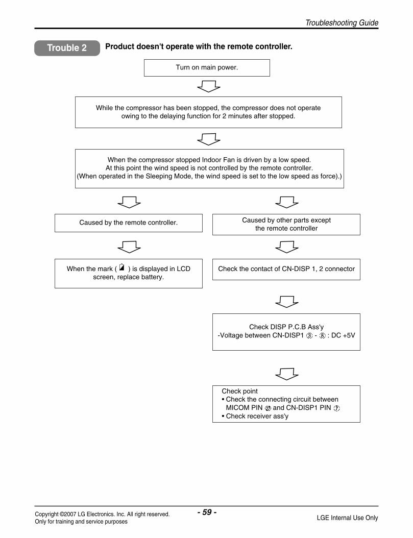
- 59 -Copyright ©2007 LG Electronics. Inc. All right reserved.Only for training and service purposes LGE Internal Use Only
Troubleshooting Guide
Turn on main power.
While the compressor has been stopped, the compressor does not operate owing to the delaying function for 2 minutes after stopped.
When the compressor stopped Indoor Fan is driven by a low speed.At this point the wind speed is not controlled by the remote controller.
(When operated in the Sleeping Mode, the wind speed is set to the low speed as force).)
Caused by the remote controller. Caused by other parts except the remote controller
When the mark ( ) is displayed in LCDscreen, replace battery.
Check the contact of CN-DISP 1, 2 connector
Check DISP P.C.B Ass'y -Voltage between CN-DISP1 - : DC +5V
Check point• Check the connecting circuit between
MICOM PIN and CN-DISP1 PIN • Check receiver ass'y
Product doesn't operate with the remote controller.Trouble 2

Troubleshooting Guide
- 60 -Copyright ©2007 LG Electronics. Inc. All right reserved.Only for training and service purposes LGE Internal Use Only
Troubleshooting for error code
Description Cause of error
1• Indoor TH. (sensor) is short or open• Indoor TH. (sensor) is not connected to the indoor pcb assembly• Damage or defect on the sensing circuit of indoor pcb assembly. (R01H, R02H, R03H, R04H, C01H, C02H)
Indoor TH. is short oropen
Indoor TH. is connected to Indoor pcb assembly ?
Indoor TH. is right ?
YES
No
- Connect to CN-TH1 in indoor pcb assembly
Sensing circuit of indoorpcb is right ?
No
Check Indoor TH.- Measure resistance of TH. (air : about 10k Ω at 25 °C, pipe : about 5k Ω at 25 °C)
YES
No
- Check soldering state of R01H ~ R04H, C01H, C02H
Check flow
2• Outdoor TH. (sensor) is short or open• Outdoor TH. (sensor) is not connected to the outdoor pcb assembly• Damage or defect on the sensing circuit of outdoor pcb assembly. (R03H~R06H, C02H, C03H)
Outdoor TH. is short oropen
DescriptionError code
Error code
Cause of error
Outdoor TH. is connected to outdoor pcb assembly ?
Outdoor TH. is right ?
YES
No
- Connect to CN-TH1 in outdoor pcb assembly
Sensing circuit of outdoorpcb is right ?
No
Check outdoor TH.- Measure resistance of TH. (air : about 10k Ω at 25 °C, pipe : about 5k Ω at 25 °C)
YES
No
- Check soldering state of R03H ~ R06H, C02H, C03H
Check flow

- 61 -Copyright ©2007 LG Electronics. Inc. All right reserved.Only for training and service purposes LGE Internal Use Only
Troubleshooting Guide
• 9K / 12K
4
• Heat-sink TH. is damaged(short or open).
• Heat-sink Temp. is over 95°C
• Damage or defect on the sensing circuit of outdoor pcb assembly. (R01H, R02H, C01H)
Heat-sink Temp. is over95°CHeat-sink TH.is open or short
Heat-sink TH. in INV-IC isRight ?
Sensing circuit of outdoorpcb is right ?
YES
No
Check heat-sink TH. - Measure resistance of TH. (about 10k Ω at 25 °C)
Heat-sink TH is connected to outdoor PCB assembly?
YES
No
- Connect to CN-TH2 in outdoor PCB assembly
No
- Check soldering state of R01H, R02H, C01H
Check flow
Cause of error
4
• Heat-sink TH. in outdoor pcb is open or short
• Heat-sink Temp. is over 95°C
• Damage or defect on the sensing circuit of outdoor pcb assembly. (R01H, R02H, C01H)
Heat-sink Temp. is over95°CHeat-sink TH. in outdoorpcb is open or short
Heat-sink TH. in outdoorpcb is Right ?
Sensing circuit of outdoorpcb is right ?
YES
No
Check heat-sink TH. - Measure resistance of TH. (about 10k Ω at 25 °C)
No
- Check soldering state of R01H, R02H, C01H
Check flowYES
Heat-sink TH. Is connectedto CN-TH2 in outdoor pcb ?
No
Connect to CN-TH2 inOutdoor pcb assembly
Description Cause of errorError code
DescriptionError code
• 18K

Troubleshooting Guide
- 62 -Copyright ©2007 LG Electronics. Inc. All right reserved.Only for training and service purposes LGE Internal Use Only
5
• Wrong or missing wiring between indoor and outdoor unit cable• Defect of communication components in indoor pcb assembly• Defect of communication components in outdoor pcb assembly• Defect of power supply components in outdoor pcb assembly• No ground connection in air conditioner unit (affected by noise in power source)
Communication Error
Wiring connectionIs right ?
Is the voltage of T/Block, in outdoor about
AC 220/240V ?
YES
No
Indoor Outdoor 1(BR) 1(BR) 2(BL) 2(BL)3(GN/YL) 3(GN/YL) 4(RD) 4(RD)
No
Check power connectorIs not connected to theT/Block in indoor unit.
Check flow
Is the voltage of GND & DC5V in Outdoor pcb about DC 5V ?
YES
No
Check FUSE, NF01/02J, PTC,Power Module, BD-01S in Outdoor pcb assembly
Communication circuit of indoor& outdoor pcb Is right ?
YES
No
Check IC01K, IC02K,D01K~D03K,ZD01K~ZD03K, R01K~R10K,C01K~C04K
Ground connection is installed ?(power outlet or outdoor chassis)
YES
No
Install ground connection from outdoorunit. (In case power outlet has no earthport)
Earth port
Description Cause of errorError code

- 63 -Copyright ©2007 LG Electronics. Inc. All right reserved.Only for training and service purposes LGE Internal Use Only
Troubleshooting Guide
Cause of error
6
• Supplied power is not normal• Comp Connector (CN-U,V,W) is disconnected or inserted to wrong position• Compressor is damaged (coil short) replace compressor• Too much Refrigerant• Defect in outdoor pcb assembly replace pcb assembly
DC Peak Error
Supplied voltage toOutdoor pcb is aboutAC 220/240V ?
Is connector (CN-U,V,W)connected to compressor and inserted to pcb in right position ?
YES
No
Check power source
No
Check CN-U,V,W connector(U : RD, V : BL, W : YL)
Check flow
Refrigerant pressure is right ?
YES
No
Check refrigerant pressureand adjust.
Is the compressor right ?
YES
No
Check resistance Between U-V, V-W, U-W port.
Short / Open circuit (Comp.motor coil error) normal : 1 ~2 Ω
Between U,V,W and Body °Ê normal : over10M Ω
Inverter components in outdoor pcb assembly areright ?
YES
No
* 9 K/12K ModelCheck
Short of SPM3 pins (GND - P, U, V, W pin) Direction of D01Z~D03Z, C08Z,10Z,12Z,16Z Assembling state of R01P ~ R21P & IC01P Assembling state of screw between INV-IC &
Heat-sink DC 15V output of Power module.
* 18 K ModelCheck
Short of SPM2 pins (GND – P, U, V, W pin) Direction of D01Z~D03Z, C08Z,10Z,12Z,16Z Assembling state of R01P ~ R21P & IC01P Assembling state of screw between INV-IC &
Heat-sink DC 15V output of Power module.
V
U
W
Ω
Description Cause of errorError code

Troubleshooting Guide
7• Supplied power is not normal• Indoor/outdoor fan is locked• Too much refrigerant• Defect in current sensing circuit in outdoor pcb assembly
Over current Error(CT2)
Supplied voltage toOutdoor pcb is aboutAC 220/240V ?
Does indoor / outdoor fan worknormally ?
YES
No
Check power source
No
Check indoor / outdoor fan andadjust.
Check flow
Refrigerant pressure is right ?
YES
No
Check refrigerant pressureand adjust.
Current sensing circuit is right ?
YES
No
Check current sensing circuit.- check CT is damaged in outdoor pcb
(output wire is disconnected to pin or not)- BD01N is inserted in right position
(refer marking on pcb and component)- Spec of R01N (1kΩ), R02N (1.65kΩ) is correct- Direction of diode (D01N, D02N) is right
Description Cause of errorError code
- 64 -Copyright ©2007 LG Electronics. Inc. All right reserved.Only for training and service purposes LGE Internal Use Only
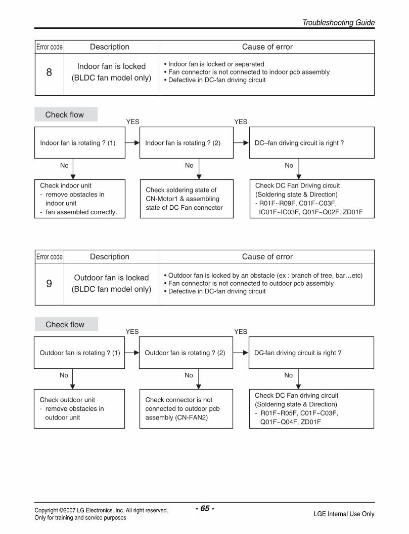
- 65 -Copyright ©2007 LG Electronics. Inc. All right reserved.Only for training and service purposes LGE Internal Use Only
Troubleshooting Guide
8• Indoor fan is locked or separated• Fan connector is not connected to indoor pcb assembly• Defective in DC-fan driving circuit
Indoor fan is locked(BLDC fan model only)
Indoor fan is rotating ? (1) Indoor fan is rotating ? (2)
YES
No
Check indoor unit- remove obstacles in indoor unit- fan assembled correctly.
No
Check soldering state of CN-Motor1 & assemblingstate of DC Fan connector
Check flow
DC–fan driving circuit is right ?
YES
No
Check DC Fan Driving circuit(Soldering state & Direction)- R01F~R09F, C01F~C03F, IC01F~IC03F, Q01F~Q02F, ZD01F
9• Outdoor fan is locked by an obstacle (ex : branch of tree, bar…etc)• Fan connector is not connected to outdoor pcb assembly• Defective in DC-fan driving circuit
Outdoor fan is locked(BLDC fan model only)
Outdoor fan is rotating ? (1) Outdoor fan is rotating ? (2)
YES
No
Check outdoor unit- remove obstacles in outdoor unit
No
Check connector is not connected to outdoor pcbassembly (CN-FAN2)
Check flow
DC–fan driving circuit is right ?
YES
No
Check DC Fan driving circuit(Soldering state & Direction)- R01F~R05F, C01F~C03F, Q01F~Q04F, ZD01F
Description Cause of errorError code
Description Cause of errorError code
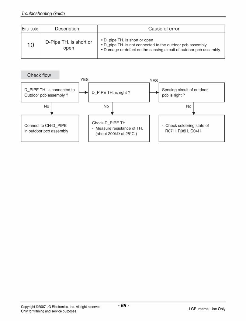
- 66 -Copyright ©2007 LG Electronics. Inc. All right reserved.Only for training and service purposes LGE Internal Use Only
Troubleshooting Guide
10• D_pipe TH. is short or open • D_pipe TH. is not connected to the outdoor pcb assembly• Damage or defect on the sensing circuit of outdoor pcb assembly
D-Pipe TH. is short oropen
D_PIPE TH. is connected toOutdoor pcb assembly ?
D_PIPE TH. is right ?
YES
No
Connect to CN-D_PIPE in outdoor pcb assembly
Sensing circuit of outdoorpcb is right ?
No
Check D_PIPE TH.- Measure resistance of TH. (about 200kΩ at 25°C.)
YES
No
- Check soldering state of R07H, R08H, C04H
Check flow
Description Cause of errorError code

- 67 -Copyright ©2007 LG Electronics. Inc. All right reserved.Only for training and service purposes LGE Internal Use Only
Wiring Diagram
Schematic Diagram
Indoor Unit Models: AS-W0964DH0, AS-W0964GH0, AS-W0964DH1
Models:AS-W1264DH0, AS-W1865DH0, AS-W1264GH0, AS-W1224DH0, AS-W1424DH0, AS-W1825DH0, AS-W096E1G0, AS-W126E1G0
Schematic Diagram
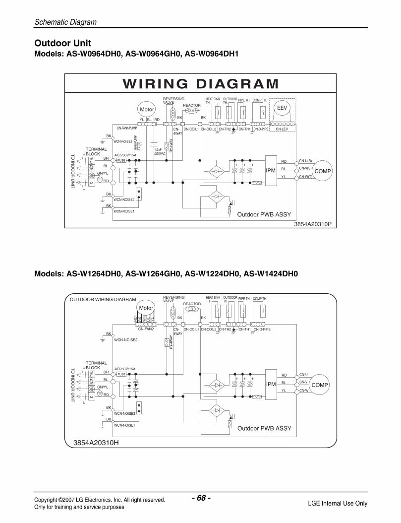
- 68 -Copyright ©2007 LG Electronics. Inc. All right reserved.Only for training and service purposes LGE Internal Use Only
Schematic Diagram
Outdoor Unit Models: AS-W0964DH0, AS-W0964GH0, AS-W0964DH1
Models: AS-W1264DH0, AS-W1264GH0, AS-W1224DH0, AS-W1424DH0

- 69 -Copyright ©2007 LG Electronics. Inc. All right reserved.Only for training and service purposes LGE Internal Use Only
Schematic Diagram
Models: AS-W1865DH0, AS-W1825DH0
Models: AS-W096E1G0, AS-W126E1G0

- 70 -Copyright ©2007 LG Electronics. Inc. All right reserved.Only for training and service purposes LGE Internal Use Only
Schematic Diagram
Components Location
• TOP VIEW
• BOTTOM VIEW
Indoor Unit Models: AS-W1264DH0, AS-W1865DH0, AS-W1264GH0, AS-W1224DH0, AS-W1424DH0, AS-W1825DH0
AS-W096E1G0, AS-W126E1G0

- 71 -Copyright ©2007 LG Electronics. Inc. All right reserved.Only for training and service purposes LGE Internal Use Only
• BOTTOM VIEW
• TOP VIEW
Schematic Diagram
Models: AS-W0964DH0, AS-W0964GH0, AS-W0964DH1

- 72 -Copyright ©2007 LG Electronics. Inc. All right reserved.Only for training and service purposes LGE Internal Use Only
C16Z
SPM3:6002EC2005CSPM3:6002EC2005D
R01
P
R12
P
R11
P
R03
P
R13
P
R14Z
22
C12
Z
21
R15Z
D03Z
25 2623
R21Z
R22Z
24
R16Z
C08
Z
1
C10
ZR13Z
D02Z
D01Z
IC02
S
IC01
S
R06
S
C19Z
17
15
13
SPM3
5
9R20Z
11
IGBT
C05
S
R05S
C06S
D01S
R02
S
R01
S
C09S
PCB : 6870A90055M_1(040221)Assy : 6871A10128
-
R03
S
2004.02.21.
-+~
BD
02S
~
R02
F
R02D
R21
P
R14
P
C05D
R02
P
L2
R17
P
R16
P
R15
P
C02D
CN-LEV
C05H
IC01
D
CN-S/VALVE2 CN-TESTCN-S/VALVE1
RD WCN-NOISE2
C09J
D03K
WCN-NOISE3BK
C01J C02J
WH
C10J
T1
ZD01K
IC02K
IC01K
CN-D_PIPE
C02F
R04
PBL-V
R23
Z
C06
D
RD-U
27
C03
DZ
D01
F
129
R01D
C01D
D01
D
87 13
L1
CN-FAN2
POWER MODULE
C07D
20YL-W
35
C02S
C03F
R01Y
16
LED01M
MICOM
R02Y
R03Y
C01Y
D01Y
OJ0
1
EEPROM
C04
DR
05F
C01C
RXD
5V
TXD
C02A
IC02M
OS
C01
B
CN-TH2
GND
C01HC04H
CN-TH1
C03H C02H
R07C
15V
D02
N
GND
R05
C
C01S
IC01A
CN-PC
J09~12(JAPAN)
J13~15(EUROPE)
J01~04(EUROPE)J01
J02
J03
J04
C03S
J09
J10
J11
J12
J13
J14
J15
J16
CN-COIL1
CN-COIL2
+~
BD
01S
~
J05~08(JAPAN)C01M
J08
J07
J05
J06
R03
C
-
~
D01NBD
01N
R01N
D01C
~
C03C
R02N
+-
C01N
RY-PUMP
CN-4WAY
CN-FAN1/PUMP
RY-H/PUMP RY-4WAY
3
+4
CT
CN-PUMP
J24
C04J C05JR09K
NF01J
ZNR01J
D01
K
R05
K
R07
K
R06
K
R08
K
FU
SE
C03K
ZD03K
ZNR02J
R01J
R06
C
D02
C
D02K
R10K
C04K
ZD02K
J23
J22
J21
J20
J19
J18
J17
WC
N-N
OIS
E1
SU
RG
E
J26
J25
R02
J
R03
J
N/F02J
RY_PWR
4
R04C
R01
C
Q01
C
~B
D01
CC
02C
R02
C
3
C08J
C06JC07J
J33
1
7
J34
J32
J31
~
PTC
J28
J27
J29
J30 J27~34(JAPAN)
C10J
WCN-NOISE3
C01J
WH
C02J
NF01J
SU
RG
E
R01J
ZNR02J
WC
N-N
OIS
E1
R03
J
J22N/F02J
J24J23
C04JC05J
J21
R02
J
J26J25
C06J
C08J
C07J
J27J30
J28
R12Z
R10Z
C08P
C06P
C01K
C01F
C02K
R01F
C15Z
R10P
D03K
C09J
WCN-NOISE2 RDBK
R02F
CN-TEST
IC02M
CN-S/VALVE1
R08Z
Q01F
R09Z
R07Z
R11Z
Q03F
33
C05H
CN-LEV
R19P
R18P
R20P
CN-S/VALVE2
L2
R17P
R16P
R15P
C02D
IC01D
R08P
C05D
C05P
IC01P
R06P
C04Z
R04Z
C01P
R05P
C02P
R07P
C03P
R09P
C03Z
C02Z
R02Z
C06Z
C05Z
R05Z
C16Z
R06Z
R03Z
D02N
R01A
17
R03AR
01M
IC01K
D01K
R07K
R09K
R08K
FUSE
R06K
C03K
ZD03K
R05K
ZNR01J
R02M
OSC01B
C01A
C04C
R01X
C01X
R02X
R07S
1
IC01M
16
R01K
C08S
R02K
R04K
IC02K
C18Z
C07S
R08S
D02C
J17
D02K
ZD02K
J19J20
J18
R02A C
02A
R07CR05C
R06C
LED01M
R10K
ZD01K
C04KIC01A
CN-PC
R04M
R03M
R08H
R06H
R05H
R03H
OJ01
R02L
Q02F
Q04F
R03F
R03Y
C01Y
R03N
EEPROM
R01L
R02Y
C02N
D01Y
1 1
64
C07P
C01T
C01B
R17H
C01C
MICOM
64
49
POWER MODULE
1213
C01D
89
D01D
C01L
C03D
C04D
ZD01F
R05F
R01D
CN-D_PIPECN-TH1
C04H
C03H
R04H
CN-TH2
C01H
C02H
R02H
R01H
CN-FAN2
C03F
R01Y
31 5R07H
R04F
C02F
R01C
RY_PWR
R08C
Q01C
R04C
R02C
+
D01N
R01N
R02N
C01N
BD01C
C03C
R03C
D01C
C02C
BD01N
J33J32
J31
J29
J34
CN-OXY2
CT
T1
+
RY-H/PUMPRY-OXY RY-4WAY
C01S
J09
J10
J11
J12
J13
J16
J15
J14
CN-FAN1/PUMPCN-4WAY
C01M
J08J07
J06
CN-COIL1
SPM3
R04P R
23Z
C04P
R02D
C06D
BL-V
RD-U
R21PR
14P
7
L1
R13P
2426
R01P
R12P
R02P
27
R21Z
R22Z
25
R16Z
R03P
R11P
C19Z
C07D
YL-W
6
8919 1720 111315
R20ZR14Z
SPM3
D03Z
R15Z
R19Z
C01Z
R01Z
C13Z
C11Z
23 22
C12Z
R18Z
21
C14Z
C17Z
R17Z
R06S
D01Z
R13Z
D02Z
5
IC01S
1
C10Z
C09Z
C08Z
C07Z
J01
J03
J02
J04
C02S
R01S
C03S
CN-COIL2
BD01S
J05
BD02S
IC02S
C06S
R02S
IGBT
R05S
D01SC05S
R03S
C09S
• TOP VIEW
Schematic Diagram
• BOTTOM VIEW
Outdoor Unit Models: AS-W0964DH0, AS-W1264DH0, AS-W0964GH0, AS-W1264GH0, AS-W1224DH0, AS-W1424DH0, AS-W0964DH1

- 73 -Copyright ©2007 LG Electronics. Inc. All right reserved.Only for training and service purposes LGE Internal Use Only
Schematic Diagram
C06J
R01J
ZNR02J
CN-FAN2
R13P
R03P
C03P R09P
IC10P
R17PR15P R16P
CN-LEV
R16Z
C15Z
C14Z
R18Z
C13Z
R17Z
R15Z
C11Z
D03ZC12Z
C09Z
Nw
SPM2
1
R01P
R02P
Nu
Nv
24
V
U
W
D02ZC10Z
C07Z
C08Z
IC01S
D01Z
R06S
C05S
C06S
R05S
D01S
23
C20Z
P
C10S
R01S
R02S
IGBT
C01S
R01L
C07S
C04P
R06P
R21P
C02P
C01PR11P
R12P
R07P
R05P
R04P
C18ZR14P
R04Z
C01
Z
R01Z
IC02S
R08Z
R08S
R07Z
R07S
R02L C08S
C06P
R19
Z
C18Z
C05
P
C17
Z
R20Z
C08P
R20P
R05Z
R10
P
C04
Z
R02Z
R08P
C02
Z
R18P
R06Z
R19P
R03
ZC
05Z
C07P
C03Z
C01X
R01
XIC
02M
C06Z
R10
Z
R09
Z
R11
Z
EEPROM
C01L
R01D
C01D
R12
Z
C01T641
MICOM
C02D
POWER MODULE
C07D
C02S
C05D
D01D
R02
D
L2
C06D
L1
IC01D
C03F
C03S
D03K
CN-PC C05HCN-TEST
C11J
FUSE
RY-PWR
Q01C
ZD03K
R06H
R17H IC01A
R02
XIC
01MR01M
OS
C01
BR02A
R01AR03A
C01A
C02A
LED01M
0J01
CN-D_PIPE
R03M
C04H
R04M
C03DC04D
R08H
C02N
R02M
C03H
R03N
R07HR05H
CN-TH1
R01K
C02
K
R05K
R07K
R06K
R02
K
C01K
R04K
IC02K
R01H
C01N
C02HR04H
C01H
R03H
CN-TH2
C01Y
IC01
K
R02H
C02F Q01F Q02F
Q04F
R05
F
R03F
ZD
01F
C01F
R02
F
R04F Q03FR01F
C04S
D01Y
R03Y
R02Y
R01Y
R02C
C02C
R01C
R04C
R03C
D01C
BD01C
JS24~25
JS26~27
D01K
R08K
R09K
NF03J
R10K
ZD01K
D02K
ZD02K
C04K
ZNR01J
SURGE
C01J
C03J
C02J
R02
J
R05CR01N
D02NC01C
C03K
D02C
R07C
R06CR02N
D01N
C03C
BD01N
NF01J
C04J
R03J
C05J
BD01S
R03
S
C09S
BD02S
CN-COIL1
CN-4AWY
CN-COIL2
JS21~23
WCN-CAP1
RY-4WAY
WCN-CAP2
RY-LRY-H
CN-FAN1
R04J
CT
T1
PTC
C07J
C08J
C09
J
NF02J
CN-FAN2
CN-LEV
PWB P/NO : 6870A90148A(030509)
10R15Z
9
8
7
6
5
4
3
2
1
R16Z
R17Z
C16Z
SPM2
IC01S
23
22
21
20
19
18
17
16
15
14
13
12
11
R14Z
R13Z
C12Z
C10Z
C10S
R05S
R06S
C08Z
C05S
C06S
IPM
R01S
R02S
R14P
PWB ASSY P/NO : 6871A20349
R13P
R03P
C18Z
Nv
Nw
Nu
25
24
RD-U
R04P
R02P
R01P
R21P
R11P
R12P
R15PR17P R16P
987
P
W
V
U
YL-W
BL-V
1312
IC02S
56 13
C07D
POWER MODULE
C06DD01D
EEPROM
C01D
GND
15V
MICOM
C03F
R01
DL2
L1
IC01D
C02D
C05D R02
D
BD01N
C03K
C01N
CN-TESTC05H CN-PC
LED01M
OS
C01
B
IC01A
OJ01
C02A
D03K
RXD
TXD
R05K
ZD03K
R06K
IC02
K
R07K
CN-TH2
C02H
CN-D_PIPE
C04DC03D
C04H
C02F
1
1
ZD
01F
R05
F
R02
F
CN-TH1
C03H
C02CD01Y
1
R03Y
C01Y
C01H
Q01C
R01C
IC01
K
ZD01K
R04C
D01C
R02Y
R01Y
BD01C
-+
C01C
R07C
R05C
R02C
R03C
R06C
D02C
C03C
+
C11J
BK(WCN-NOISE1)FUSE
RD
JS26~27
ZD02K
R09K
R08K
D01K
NF03J
ZNR02J
BR BL
R01J
ZNR01J
SURGE
D02K
C04K
R10K
JS24~25
JS01~05
NF01J
-
R02N
R01N
D02N
D01N
C01J
C03J
C02J
BK
(WC
N-N
OIS
E2)
JS06~10
BK(WCN-NOISE3)
CN-FAN1
~-
D01S
R03
S
C09S
~ + -
IGBT
BD02S
JS21~23
CN-COIL1
~~
C01S
+
CN-4WAY
CN-COIL2
C02S
BD01S
RY-4WAYRY-HRY-L
C03S
WCN-CAP2 WCN-CAP1
3
CT
4 7
C04S
T1
1
PTC
3
RY-PWR
C07J
C08J
4
C09
J
JS16~20
BK(WCN-NOISE4)
JS11~15
C06J
C04J
C05J
NF02J
• TOP VIEW
• BOTTOM VIEW
Models: AS-W1865DH0, AS-W1825DH0
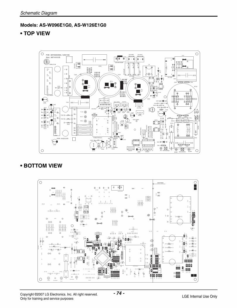
Schematic Diagram
- 74 -Copyright ©2007 LG Electronics. Inc. All right reserved.Only for training and service purposes LGE Internal Use Only
D02N
R02
X
C01K
CN
_S/V
ALV
E2
CN
-Fla
sh W
riter
R05
K
WCN-NOISE3BL/WH
C08J
C02J
WCN-NOISE2
BR/BKCN-LEV
RD
R07
K
R06
K
FU
SE
C01J
R03
K
C09J
D03KIC02M
C08B
NF01J
C04J
R01J
SU
RG
E
WC
N-N
OIS
E1
ZNR02J
J28
R02
J
J29
J32
J31
J30
R03
J
C02
K
C03J C03K
ZD
03K
D01
K
R08K
ZNR01J
R09K
1
CN
_S/V
ALV
E1
R02
K
R04
K
IC01K
R01
K
IC02K
IC01M
R10K
J23
D02K
ZD02K
J25
J27
J26
J24
R01
M
ZD01K
16
LED
01M
C04K
R03
B
POWER MODULE
R04
C
R06
S
R23
P
R22
P
R24
P
R13
Z
CN-D/A
EEPROM
C02
YR03
N
C02
BC
02N
C10
S
C01
C
C01
LR
01L
C18
Z
C01
FR
01F
R04
YR
02B
C09
B
-80
R02
L
C05H
IC01
D
C03
D
C02D
R07
H
R03
HR
01H
R05
H
C04DC01
H
C05D
C04
P
C03
P
C02
P
R21
P
R19
P
R20
P
R06
P
R03
P
C01
P
R18
PR
07P
R04
PR
16P
C05
P
R17
ZR
02P
R17
PR
05P
R01D
L1 C01D
R01
P
R25
ZR
06Z
R23
ZR
24Z
R04
ZR
05Z
27
IC01P
R01Y
R03X
IC01
AC
01B
R02
HR
04B
OS
C01
B
TEST POINT
C04
BR
01B
C03
B
R05
B
C01
X
C05
B
R01
A
C01
A
R06
B
MIC
OM
C07
B
R04
X
Q03
FC
06B
R06
H
R04
H
R08
H
Q01
F
CN
-FLA
SH
C01
Y
R05
F
R03
Y
C02H
Q02
F
R01W
C03H
R02
A
R03
A
C02A
CN-TH1CN-TEST
R01
X
C02X
R05
X
CN-PC
ZD
01F
R04
F
C03F
CN-FAN2
R02
Y
R02
FD
01Y
C04H
CN-D_PIPE
R03
F
Q04
F
C02F
BL-
VR
D-U
R11
PR
09P
R13
PR
14P
R08
P
R19
ZR
18Z
R14Z
R12
PR
10P
R15
P
R15Z
YL-
W
C06D
SPM3
R16Z
C19Z
CN-4WAY
J22
NF02J
C06J
PTC
C07J
BD01N
IC01
C
C05J
C01N
R01N
D01N
R02N
R03
C
RY-PWR
J18
J19
J20
J21
J17
D02
C
CT
+
D01
CR
01C
R02
C
J09
J10
J16
J11
J13
J12
C02S
C01S
J15
J14
RY
-4W
AY
RY
-H/P
UM
P
RY
-PU
MP
CN
-CO
IL1
C03S
R03
S
CN
-CO
IL2
J08
J07
J06
J01
J04
J03
J02
J05
CN-PUMP
CN-FAN1/PUMP
C01M
HEATSINK
R12
Z
R22
Z
R21
Z
R20
Z
C04
Z
C05
Z
C06
Z
R03
Z
R02
Z
R01
Z
C16Z
C15
Z
C10Z R08Z
C12Z
C01
Z
C11
Z
D03Z
R09Z
C13
Z
C14
Z
C03
Z
C17
Z
C02
Z
R11Z
C08Z
C07
ZC
09Z
C08S
D01Z
R07Z
D02Z
C05
S
R04
S
C06
S
R01
S
C07
SC
09S
R05
SC
04S
R02S
BL/WH
D02NC03F
D01
Y
7
6
SPM3 : 6002EC2005
1
SPM3
C16Z
C02D C03
D
C01D
21
1 53
POWER MODULE
L1
R01D
C19Z
R14Z
R16Z
R08Z
R09Z
D03Z
R11Z
15
R15Z13
11
9
5
C12Z
C08S
D01Z
R07Z
D02Z
C08Z
20
17
C10Z
2625
2422
23
RD-U
BL-V
13 12 9 8
R18ZR19Z
R17Z
27
YL-W R02
Y
R01YCN-FAN2
C06D
CN
_S/V
ALV
E2CN
_S/V
ALV
E1
CN
-Fla
sh W
riter
CN-LEV
IC01D
CN-D/AC05H
C04D
C05D
C01HC08B
EE
PR
OM
IC02
M
WCN-NOISE2RDWCN-NOISE3BR/BK
R06
K
R07
K
D03K
C09J
R05
K
C01J C02J
FU
SE
C02S
OS
C01
BIC
01A
C06B
1
C01
Y
CN
-FLA
SH
R03
YCN-PC
TEST POINT
C04B
C03H
CN-TH1
C02HC02F
ZD
01F
CN-D_PIPE
C04H C02A
CN-TEST
R09K
R08
K
D01
K
ZD
03K
IC01K
IC02K
C03J C04J
NF01J
ZNR01J
D02K
ZD02K
C03K
C04K
LED
01M
R10K
ZD01K
J25
J24
J26
J27
J23
CN
-CO
IL29
PSC_Module
2423
2122
111
5
9
R02S
2726
2005.01.06
2015
17
2513
C03S
R03
S J03
J02
C01M
J01
J05
J07J06
J04
J08
PCB : 6870A90055Q_1(050106)
Assy : 6871A10135
J20
J21
J22
J19
CT
+J09
J14
J15
J11
J12
J10
J13
J16
RY
-H/P
UM
P
CN
-CO
IL1
C01S RY
-4W
AY
RY-PUMP
BD
01N
IC01
C
D01
N
C01N
-
R01N
R02N
C05J
RY-PWR
D01
C
R01
C
D02
C
R02
C
~~
J17
J18
4
C07J
CN-FAN1/PUMP
CN-4WAYCN-PUMPPTC
3
C08J
WC
N-N
OIS
E1
SU
RG
E
ZNR02J
R01J
J29
J28
J32
J30
J31
R03
J
R02
J
NF02J
C06J
• TOP VIEW
• BOTTOM VIEW
Models: AS-W096E1G0, AS-W126E1G0

Schematic Diagram
DISPLAY ASSEMBLY
– 6871A20574A
– 6871A20624A
- 75 -Copyright ©2007 LG Electronics. Inc. All right reserved.Only for training and service purposes LGE Internal Use Only

- 76 -Copyright ©2007 LG Electronics. Inc. All right reserved.Only for training and service purposes LGE Internal Use Only
Product Specifications
Product Specifications Table-1
Model Name
Item UnitW
MIN kcal/h.(W)Btu/h.
WCooling Capacity Type kcal/h.(W)
Btu/h.W
Max kcal/h.(W)Btu/h.
WMIN kcal/h.(W)
Btu/h.W
Heating Capacity Type kcal/h.(W)Btu/h.
WMax kcal/h.(W)
Btu/h.IN:20°C,Out: -10°C(Heater ON) Btu/h.IN:20°C,Out: -10°C(Heater OFF) Btu/h.
Power Input Cooling WHeating WHeating(-10°C,Heater ON) WHeating(-10°C,Heater OFF) W
Running Current Cooling AHeating AHeating(-10°C,Heater ON) AHeating(-10°C,Heater OFF) A
Starting Current Cooling AHeating ACooling kcal/hW
EER Btu/h.WHeating kcal/hW
Btu/h.WCOP Cooling W/W
Heating W/WPower Supply Ø,V,HzPower Factor %Air Circulation Indoor,Max m3/min(CFM)
Outdoor,Max m3/min(CFM)Moisture Removal l/h.(pts/h.)Noise Level Indoor,High dB(A)±3(Sound Med. dB(A)±3Pressure,1m) Low dB(A)±3
Outdoor,Max dB(A)±3Refrigerant(R410A)ChargePower Cord AWG#:P*mm2
Connecting Cable AWG#:P*mm2
Connecting Tube Liquid Side mm(in)(Ø. Socket Flare) Gas Side mm(in)
Length,std m(in)Drain Hose (O.D , I.D) mm(in)
Indoor mmDimension inch(W*H*D) Outdoor mm
inchNet Weight Indoor kg(lbs)
Outdoor kg(lbs)
1,758 1,143 2,7551,512 983 2,3696,000 3,100 9,4002,637 3,516 5,2742,268 3,024 4,5369,000 12,000 18,0003,033 4,043 6,0962,608 3,478 5,242
10,350 13,800 20,8001,465 879 1,4061,260 756 1,2105,000 3,000 4,8003,296 4,043 6,0652,835 3,478 5,216
11,250 13,800 20,7003,810 4,659 6,6513,276 4,007 5,720
13,000 15,900 22,700- - -- - -
690 970 1,640910 1,120 1,680
- - -- - -
3.4 4.2 74.2 5.1 8
- - -- - -
3.4 4.2 7.54.2 5.1 8.53.29 3.29 2.813.04 13.04 10.983.12 3.12 3.1110.36 12.32 12.323.82 3.82 3.223.62 3.61 3.61
1,220-240,50 1,220-240,50 1,220-240,5097 97 97
7.2(254) 8.7(307) 13.0(459)26(918) 26(918) 42(1483)
1.4(2.94) 1.5(3.2) 2.1238 40 4235 37 -29 31 3648 49 55
810(26.5) 845(28.5) 1,200(40.8)16:3*1.0 16:3*1.0 12:3*2.516:4*1.0 16:4*1.0 12:4*2.56.35(1/4) 6.35(1/4) 6.35(1/4)9.52(3/8) 12.7(1/2) 12.7(1/2)7.5(295) 7.5(295) 7.5(295)
21.5,16.0(0.85,0.63) 21.5,16.0(0.85,0.63) 21.5,16(0.85,0.63)758*260*160 758*260*160 758*260*16029.8*10.2*6.3 29.8*10.2*6.3 29.8*10.2*6.3770*540*245 770*540*245 770*540*24530.3*21.3*9.6 30.3*21.3*9.6 30.3*21.3*9.6
9(20) 9(20) 13.5(30)38(83.8) 38(83.8) 60(132.3)
AS-W0964DH0AS-W0964GH0
AS-W1264DH0AS-W1264GH0 AS-W1865DH0

- 77 -Copyright ©2007 LG Electronics. Inc. All right reserved.Only for training and service purposes LGE Internal Use Only
Product Specifications
Table-2
Model Name
Item UnitW
MIN kcal/h.(W)Btu/h.
WCooling Capacity Type kcal/h.(W)
Btu/h.W
Max kcal/h.(W)Btu/h.
WMIN kcal/h.(W)
Btu/h.W
Heating Capacity Type kcal/h.(W)Btu/h.
WMax kcal/h.(W)
Btu/h.IN:20°C,Out: -10°C(Heater ON) Btu/h.IN:20°C,Out: -10°C(Heater OFF) Btu/h.
Power Input Cooling WHeating WHeating(-10°C,Heater ON) WHeating(-10°C,Heater OFF) W
Running Current Cooling AHeating AHeating(-10°C,Heater ON) AHeating(-10°C,Heater OFF) A
Starting Current Cooling AHeating ACooling kcal/hW
EER Btu/h.WHeating kcal/hW
Btu/h.WCOP Cooling W/W
Heating W/WPower Supply Ø,V,HzPower Factor %Air Circulation Indoor,Max m3/min(CFM)
Outdoor,Max m3/min(CFM)Moisture Removal l/h.(pts/h.)Noise Level Indoor,High dB(A)±3(Sound Med. dB(A)±3Pressure,1m) Low dB(A)±3
Outdoor,Max dB(A)±3Refrigerant(R410A)ChargePower Cord AWG#:P*mm2
Connecting Cable AWG#:P*mm2
Connecting Tube Liquid Side mm(in)(Ø. Socket Flare) Gas Side mm(in)
Length,std m(in)Drain Hose (O.D , I.D) mm(in)
Indoor mmDimension inch(W*H*D) Outdoor mm
inchNet Weight Indoor kg(lbs)
Outdoor kg(lbs)
900 900770 770
3,070 3,0702,630 3,5102,260 3,0209,000 12,0003,700 4,0403,180 3,47012,620 13,800
900 900770 770
3,070 3,0703,600 4,5703,100 3,93012,300 15,6005,000 5,4804,300 4,71017,060 18,720
- -- -
650 1,090870 1,260
3 4.84 5.7- -- -3 4.84 5.7
3.48 2.7713.85 11.013.56 3.1214.14 12.384.05 3.234.14 3.63
1,220-240,50 1,220-240,5097 97
8.5(300) 9.5(335)29(1,024) 29(1,024)0.6(1.28) 1.3(2.77)
33 3929 2925 2548 48
1,000(34.0) 1,000(34.0)16:3*1.0 16:3*1.016:4*1.0 16:4*1.06.35(1/4) 6.35(1/4)9.52(3/8) 9.52(3/8)7.5(295) 7.5(295)
21.5,16.0(0.85,0.63) 21.5,16.0(0.85,0.63)895*282*165 895*282*16535.2*11.1*6.5 35.2*11.1*6.5770*540*245 770*540*24530.3*21.3*9.6 30.3*21.3*9.6
10(22) 10(22)38(83.8) 38(83.8)
AS-W096E1G0 AS-W126E1G0

- 78 -Copyright ©2007 LG Electronics. Inc. All right reserved.Only for training and service purposes LGE Internal Use Only
Product Specifications
Table-3
Buyer Models
Item Unit
Min. kcal/h.(W)Btu/h.
Cooling Capacity Type kcal/h.(W)Btu/h.
Max. kcal/h.(W)Btu/h.
Min. kcal/h.(W)Btu/h.
Heating Capacity Type kcal/h.(W)Btu/h.
Max. kcal/h.(W)Btu/h.
Power Input Cooling WHeating W
Running Current Cooling AHeating A
Starting Current Cooling AHeating ACooling kcal/hW
EER Btu/h.WHeating kcal/hW
Btu/h.WCOP Cooling W/W
Heating W/WPower Supply Ø,V,HzPower Factor %Air Circulation Indoor,Max m3/min(CFM)
Outdoor,Max m3/min(CFM)Moisture Removal µP/h.(pts/h.)Noise Level Indoor,High dB(A)±3(Sound Med. dB(A)±3Pressure,1m) Low dB(A)±3
Outdoor,Max dB(A)±3Refrigerant(R410A)ChargePower Cord AWG#:P*mm2
Connecting Cable AWG#:P*mm2
Connecting Tube Liquid Side mm(in)(Ø. Socket Flare) Gas Side mm(in)
Length,std m(in)Drain Hose (O.D , I.D) mm(in)Dimension Indoor mm(W*H*D) inch
Outdoor mminch
980(1,140) 989(1,150) 1,548(1,800)3,890 - 6,142
3,024(3,517) 3,528(4,102) 4,536(5,274)12,000 14,000 18,000
3,474(4,040) 3,732(4,340) 4,987(5,800)13,800 14,810 19,790
757(880) 765(892) 1,204(1,400)3,003 3039 4,777
3,478(4,043) 3,780(4,396) 5,242(6,096)13,800 15,000 20,800
4,007(4,660) 4,119(4,790) 5,761(6,700)15,900 16,344 22,861 1,100 1,320 1,600 1,120 1,300 1,685
5.0 5.9 7.0 5.1 5.8 8.0 5.0 6 7.5 5.5 7.1 8.5
2.75 2.67 2.84 10.91 10.61 11.25 3.11 2.91 3.11 12.32 11.54 12.34 3.20 3011 3.30 3.61 3.38 3.62
1,220,60 1, 220, 60 1,220,6097 97 97
8.7(307) 8.7(307) 13.0(459)26(918) 26(918) 42(1483)1.5(3.2) 1.5(3.2) 2.12
40 40 42 37 37 -29 29 36 49 49 55
845(28.5) 915 1200(40.8)16:3*1.0 16:3*1.0 12:3*2.516:4*1.0 16:4*1.0 12:4*2.56.35(1/4) 6.35(1/4) 6.35(1/4)12.7(1/2) 12.7(1/2) 12.7(1/2)7.5(295) 7.5(295) 7.5(295)
21.5,16.0(0.85,0.63) 21.5,16(0.85,0.63) 21.5,16(0.85,0.63)758*260*160 758*260*160 1090*300*17829.8*10.2*6.3 29.8*10.2*6.3 42.9*11.8*7.0770*540*245 770*540*245 870*655*32030.3*21.3*9.6 30.3*21.3*9.6 34.3*25.8*12.6
AS-W1224DH0 AS-W1424DH0 AS-W1825DH0
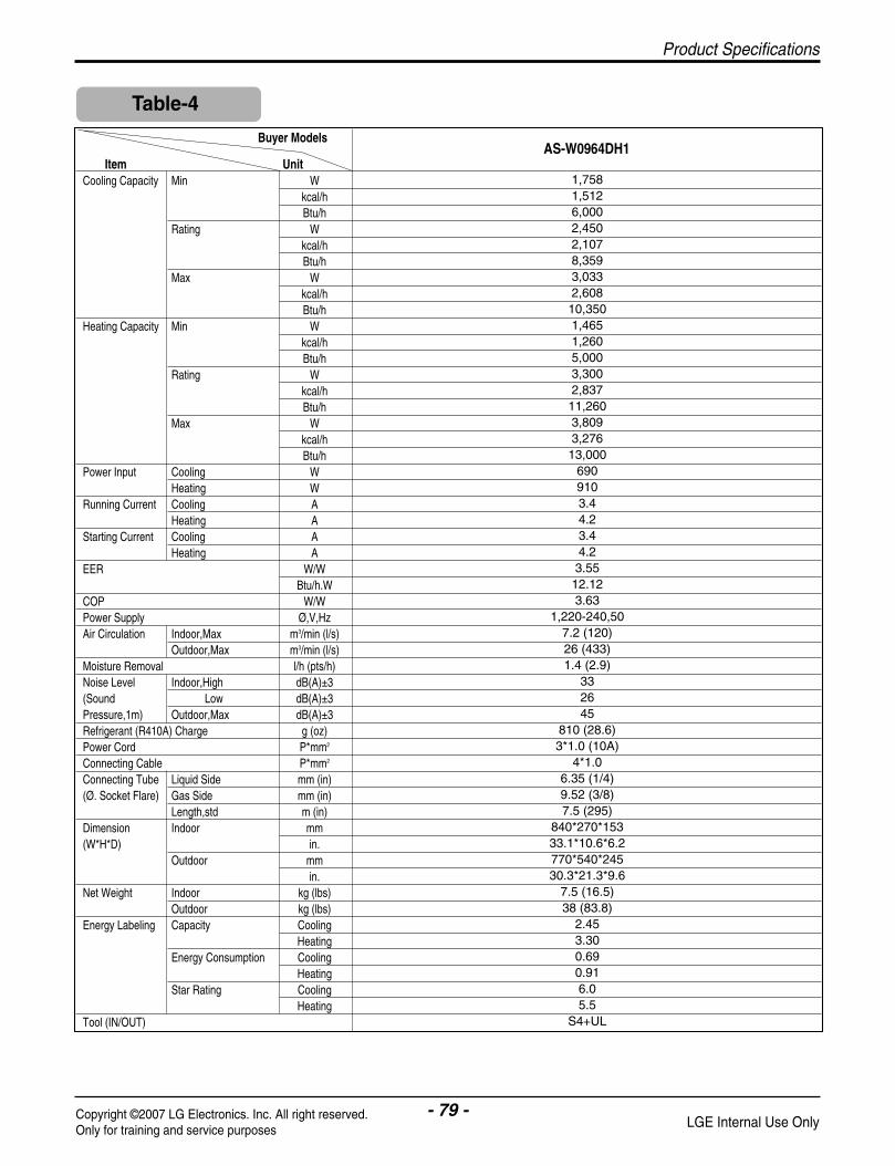
- 79 -Copyright ©2007 LG Electronics. Inc. All right reserved.Only for training and service purposes LGE Internal Use Only
Product Specifications
Table-4
Buyer Models
Item UnitCooling Capacity Min W
kcal/hBtu/h
Rating Wkcal/hBtu/h
Max Wkcal/hBtu/h
Heating Capacity Min Wkcal/hBtu/h
Rating Wkcal/hBtu/h
Max Wkcal/hBtu/h
Power Input Cooling WHeating W
Running Current Cooling AHeating A
Starting Current Cooling AHeating A
EER W/WBtu/h.W
COP W/WPower Supply Ø,V,HzAir Circulation Indoor,Max m3/min (l/s)
Outdoor,Max m3/min (l/s)Moisture Removal l/h (pts/h)Noise Level Indoor,High dB(A)±3(Sound Low dB(A)±3Pressure,1m) Outdoor,Max dB(A)±3Refrigerant (R410A) Charge g (oz)Power Cord P*mm2
Connecting Cable P*mm2
Connecting Tube Liquid Side mm (in)(Ø. Socket Flare) Gas Side mm (in)
Length,std m (in)Dimension Indoor mm(W*H*D) in.
Outdoor mmin.
Net Weight Indoor kg (lbs)Outdoor kg (lbs)
Energy Labeling Capacity CoolingHeating
Energy Consumption CoolingHeating
Star Rating CoolingHeating
Tool (IN/OUT)
1,758 1,512 6,000 2,450 2,107 8,359 3,033 2,608 10,350 1,465 1,260 5,000 3,300 2,837 11,260 3,809 3,276 13,000
690 910 3.44.23.44.23.55 12.12 3.63
1,220-240,507.2 (120)26 (433)1.4 (2.9)
332645
810 (28.6)3*1.0 (10A)
4*1.06.35 (1/4)9.52 (3/8)7.5 (295)
840*270*15333.1*10.6*6.2770*540*24530.3*21.3*9.6
7.5 (16.5)38 (83.8)
2.45 3.30 0.69 0.91 6.0 5.5
S4+UL
AS-W0964DH1

- 80 -Copyright ©2007 LG Electronics. Inc. All right reserved.Only for training and service purposes LGE Internal Use Only
Exploded View
Exploded View
152302A
152302B
342800
264110
263230A
359011
131410 733010
135316
135314
135311
147581
268711A
146811
346810
266090
13551635211B
W0CZZA
352150
354210
249951 268711D267110
152313
159830
Option Parts
Part forPlasma Models
Part forPlasma Models
Indoor Unit

- 81 -Copyright ©2007 LG Electronics. Inc. All right reserved.Only for training and service purposes LGE Internal Use Only
Exploded View
Outdoor Unit Models: AS-W0964DH0, AS-W1264DH0AS-W0964GH0, AS-W1264GH0, AS-W1224DH0,
AS-W1424DH0, AS-W0964DH1 (UL Chassis)
554031
435511
552202
552116
554160
561410
552111
550140 552203B
552203A
430411
649950
437211
435301
559010
349480
546810
349600
261704
447910
263230A
263230B
668711F
Part forH/P Models
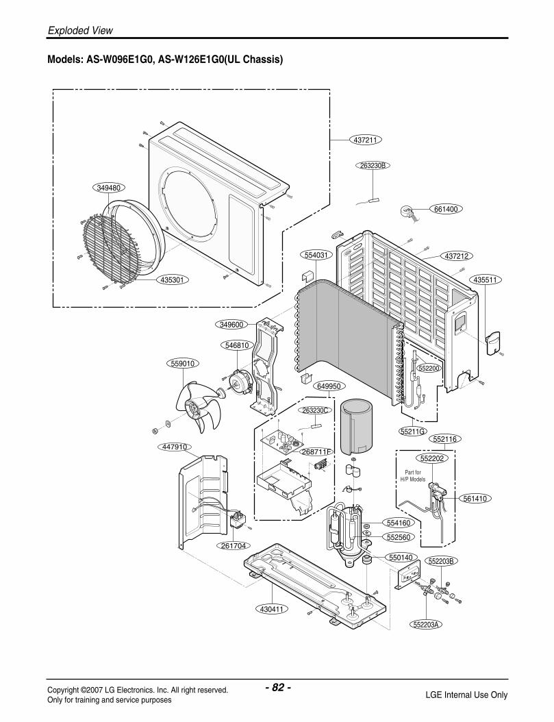
- 82 -Copyright ©2007 LG Electronics. Inc. All right reserved.Only for training and service purposes LGE Internal Use Only
Exploded View
Models: AS-W096E1G0, AS-W126E1G0(UL Chassis)
554031
435511
552202
552116
554160
552560
561410
550140 552203B
552203A
430411
649950
437211
661400
437212
435301
559010
546810
349600
261704
447910
263230B
263230C
268711F
55211G
552200
Part forH/P Models
349480

- 83 -Copyright ©2007 LG Electronics. Inc. All right reserved.Only for training and service purposes LGE Internal Use Only
554031
437212
263230A
435511
552202
567502
552116
554160
561410
435512
550140 552203B
552203A
430411
437210
649950
552111
559010
546810
349600
447910
263230B
Part forH/P Models
Models: AS-W1865DH0, AS-W1825DH0 (UE Chassis)
Exploded View
P/No.: 3828A20462G JAN, 2008


![LG Air Conditioner SVC MANUAL(Exploded View) · LG Air Conditioner SVC MANUAL(Exploded View) MODEL : AMNW09GL1A0 [LMDN096HV] AMNW12GL2A0 [LMDN126HV] AMNW18GL2A0 [LMDN186HV] Type:](https://static.fdocuments.in/doc/165x107/5adcc51d7f8b9ae1408bfb6c/lg-air-conditioner-svc-manualexploded-view-air-conditioner-svc-manualexploded.jpg)