
ROOF DESIGNS AND AFFECTING THERMAL COMFORT FACTORS …orca.cf.ac.uk/71492/1/Final Thesis with...
409
1 ROOF DESIGNS AND AFFECTING THERMAL COMFORT FACTORS IN A TYPICAL NATURALLY VENTILATED MALAYSIAN MOSQUE By SHAFIZAL MAAROF (0543482) Submitted in accordance with the requirements for the degree of Doctor of Philosophy (PhD) Cardiff University School of Architecture 2014
Transcript of ROOF DESIGNS AND AFFECTING THERMAL COMFORT FACTORS …orca.cf.ac.uk/71492/1/Final Thesis with...

1
ROOF DESIGNS AND AFFECTING THERMAL COMFORT FACTORS IN A
TYPICAL NATURALLY VENTILATED MALAYSIAN MOSQUE
By
SHAFIZAL MAAROF
(0543482)
Submitted in accordance with the requirements for the degree of Doctor of Philosophy
(PhD)
Cardiff University
School of Architecture
2014

2

i
ACKNOWLEDGEMENTS
I would like to thank God for giving me the opportunity to further my study at this level. The
experience that I got through the journey of the study is priceless. The challenges and
hardship in conducting the research have taught me to be a better person. I would also
like to thank my wife, Ruzita and my children, Atiqah, Haikal Uzair and Farhan for being
with me and giving support and sacrifices throughout the journey. I know that all of you
have tolerated so many things in your lives to make the study a success. A special thank
too for those who have helped me in this study especially the Mosque Authority of the
selected mosques who had allowed me to stay and conduct the study inside the mosques.
Not to forget, all the staff of Welsh School of Architecture, Cardiff University who has been
very helpful in assisting me during my stay in Cardiff. Lastly, to my late beloved mother
who passed away while I was thousands miles away from you, I always pray that God will
grant His blessings for you at all time. I am sorry that I could not be with you during your
last moment.

ii
Abstract
The local climate of Malaysia with high air temperature and relative humidity and
inconsistent air movement throughout the day provides challenges for architects and designers to
design a building including a mosque that can provide better indoor thermal condition. Thermally
uncomfortable indoor environment in a typical Malaysian mosque can be sensed due to the poor
attendance of believers during communal prayers conducted five times a day at the mosque. A
study was carried out in four typical mosques in Malaysia to investigate the thermal comfort level
together with what and how the thermal comfort factors affecting the condition. They study also
looks at the influence of roof design of the mosque in affecting thermal condition inside the prayer
hall since the roof design is a significant feature of the building not only as a filter to the outdoor
climate but also as the identity of the building and the society. From the investigation, it has been
revealed that air temperature is the primary factor in affecting thermal comfort. When the air
temperature is at neutral or comfort temperature, the presence of other factors can be ignored.
However, when the primary factor is no longer at its neutral condition, the secondary factors which
are air movement and humidity will play their roles in influencing thermal comfort in naturally
ventilated mosques in Malaysia. In many cases, air movement is always desirable and able to
improve the thermal comfort level. Therefore, the need for the availability of air movement should
be particularly considered in designing a mosque to ensure that the mosque is thermally
comfortable. The research has also discovered that the pitched and doomed roofs have different
abilities to control the distribution of air, for examples, the pitch roof mosque has the ability to
circulate the air inside the prayer hall to achieve the equilibrium state whereas the domed roof
mosque has the ability to stratify the air according to the temperature where the coolest air located
at the lowest level of the space. With the pitch roof, a mosque is able to create air movement
inside the space whereas the dome roof mosque will provide stagnant but cooler air at the active
level due to the stratification process. Due to these findings, the pitched roof mosque is considered
a better option for this climate for its ability to provide natural air circulation inside the space which
is desirable by the users. With the understanding on the ability of the roof designs namely, domed
and pitched roof in controlling air movement of the interior and the interdependencies of the main
factors affecting thermal comfort, strategies for improvement on the design of the mosque can be
made to achieve better indoor thermal condition of the prayer hall.
Keywords: thermal comfort, air temperature, air movement, naturally ventilated, mosque, roof
design.

iii
Contents
ACKNOWLEDGEMENTS .................................................................................................... i
Abstract ............................................................................................................................... ii
List of Figures ...................................................................................................................... x
List of Tables .....................................................................................................................xiv
CHAPTER ONE - INTRODUCTION .................................................................................... 1
1.1 Introduction ............................................................................................................ 1
1.2 Purpose of the research ......................................................................................... 6
1.3 Research Scope ..................................................................................................... 7
1.3 Outline of the Thesis ............................................................................................ 10
CHAPTER 2 – MALAYSIA AND ITS MOSQUES .............................................................. 13
2.1 Introduction .......................................................................................................... 13
2.2 BACKGROUND OF MALAYSIA ........................................................................... 13
2.2.1 INTRODUCTION .......................................................................................... 13
2.2.2 CLIMATE ................................................................................................... 14
2.2.3 Wind Flow ...................................................................................................... 15
2.2.4 Rainfall Distribution ........................................................................................ 16
2.3 POPULATION .................................................................................................. 18
2.4 RELIGION AND CULTURE ................................................................................ 19
2.5 What is a Mosque? .............................................................................................. 20

iv
2.5.1 The Elements of a Mosque ........................................................................... 20
2.6 The Development of Malaysian Mosque: Islamic vs. Traditional Identity ............. 23
2.7 Typical Characteristics of Contemporary Malaysian Mosques ............................. 32
2.8 Conclusion ........................................................................................................... 37
CHAPTER 3 ...................................................................................................................... 38
LITERATURE REVIEW ON THERMAL COMFORT IN TROPICS ................................ 38
3.1 What is Thermal Comfort? ................................................................................ 38
3.2 FACTORS AFFECTING THERMAL COMFORT FOR TROPICAL
COUNTRIES. ................................................................................................................ 39
3.3 THERMAL COMFORT IN TROPICAL COUNTRIES ........................................... 47
3.4 THERMAL COMFORT STUDIES IN MALAYSIA ................................................. 52
3.5 evaluative methods in thermal comfort ................................................................. 59
3.5.1 Static / controlled lab studies ......................................................................... 59
3.5.2 Adaptive studies ............................................................................................ 60
3.6 Applicability of the thermal comfort models .......................................................... 61
2.2.1 Fanger’s Predicted Mean Vote (PMV) model ................................................ 61
2.2.2 Adapative Thermal Comfort model ................................................................ 62
3.7 Conclusion ............................................................................................................. 65
CHAPTER 4 - METHODOLOGY ...................................................................................... 67
v
4.1 Introduction .......................................................................................................... 67
4.2 Background ......................................................................................................... 69
4.3 The Case Study ................................................................................................... 70
4.3.1 Selection of Buildings .................................................................................... 72
4.3.2 Selection of Participants ................................................................................ 85
4.3.3 Data Collection .............................................................................................. 85
4.3.4 Data Analysis ................................................................................................ 91
4.4 Computer Modeling .............................................................................................. 94
4.4.1 The Mosque Model – Dome and Pitch .......................................................... 98
4.4.2 Data Collection .............................................................................................. 98
4.4.3 Data Analysis ............................................................................................... 102
4.5 Conclusion ........................................................................................................... 103
CHAPTER 5 – RESULTS AND DISCUSSION ................................................................ 105
( Survey and Field Measurement) ................................................................................... 105
5.1 INTRODUCTION ................................................................................................ 105
5.2 General Background .......................................................................................... 105
5.3 Pilot Study ....................................................................................................... 107
5.4 Case Study 1 – Al Azim Mosque, Melaka, Malaysia .......................................... 110
5.4.1 Thermal Comfort Perception ........................................................................ 111

vi
5.4.2 Affecting factors and preferences on thermal comfort ................................. 113
5.4.3 Application of ASHRAE 7 thermal Sensation Scale and Bedford scale in
predicting acceptable air temperature ...................................................................... 120
5.5 Case Study 2 : Jamek Mosque, Seremban, Malaysia ....................................... 124
5.5.1 Thermal comfort perception ......................................................................... 124
5.5.2 Affecting factors and preferences on thermal comfort .............................. 126
5.5.3 Application of ASHRAE 7 thermal Sensation Scale and Bedford scale in
predicting acceptable air temperature ..................................................................... 133
5.6 Case Study 3: Masjid Qariah Sikamat, Seremban, Malaysia ............................ 135
5.6.1 Thermal comfort perception ............................................................................ 136
5.6.2 Affecting factors and preferences on thermal comfort ................................. 139
5.6.3 Application of ASHRAE 7 thermal Sensation Scale and Bedford scale in
predicting acceptable air temperature ...................................................................... 143
5.7 Al Mizan Mosque, Putrajaya............................................................................... 146
5.7.1 Thermal Comfort Perception ........................................................................ 147
5.7.2 Affecting factors and preferences on thermal comfort ................................. 149
5.7.3 Application of ASHRAE 7 thermal Sensation Scale and Bedford scale in
predicting the acceptable air temperature .............................................................. 156
5.8 Discussion .......................................................................................................... 158
5.9 Conclusion ......................................................................................................... 165
vii
CHAPTER 6 – RESULTS AND DISCUSSION: HTB2 and WinAir4 Simulation ............... 168
6.1 Introduction ..................................................................................................... 168
6.2 The simulation................................................................................................. 169
6. 3 Conclusion ............................................................................................................ 194
Chapter 7 – Discussion and Proposal ............................................................................. 197
7.1 Introduction ........................................................................................................ 197
7.2 Thermal Comfort Condition in a Typical Malaysian Mosque .............................. 197
7.3 Factors affecting thermal comfort level .............................................................. 204
7.3.1 Space Air Temperature and Thermal Comfort ............................................. 205
7.3.2 Humidity and Thermal Comfort .................................................................... 206
7.3.3. Wind Condition and Thermal Sensation ...................................................... 207
7.4 Thermal Comfort Range and Indexes ................................................................ 210
7.5 design guidelines proposal ................................................................................. 215
a. Reducing the Mean Radiant Temperature (MRT) ........................................... 217
b. Improving the natural ventilation ..................................................................... 220
7.6 Conclusion ......................................................................................................... 225
CHAPTER 8 – CONCLUSION ........................................................................................ 228
8.1 INTRODUCTION ................................................................................................ 228
8.2 RESEARCH PROCESS, AIMS AND OBJECTIVES .......................................... 229

viii
8.3 FINDINGS .......................................................................................................... 230
8.4 CONSTRAINTS AND LIMITATIONS ................................................................. 241
8.5 IMPLICATION ON THE MOSQUE DEVELOPMENT ......................................... 242
8.6 FUTURE RESEARCH ........................................................................................ 247
8.6 CONCLUDING REMARKS ................................................................................ 249
APPENDIX A ................................................................................................................... 251
SET OF QUESTIONNAIRES ....................................................................................... 251
APPENDIX B ................................................................................................................... 257
COMPILED DATA FROM FIELD MEASUREMENT AND SURVEY ............................ 257
1. FIELD MEASUREMENT DATA FROM TINYTAG DATA LOGGER .................. 258
i. MASJID JAMEK, SEREMBAN, NEGERI SEMBILAN ....................................... 258
ii. MASJID AL AZIM, MELAKA, MALAYSIA ........................................................... 260
iii. MASJID AL MIZAN, PUTRAJAYA MALAYSIA ............................................... 263
iv. Masjid Sikamat, Seremban, Negeri Sembilan ................................................. 265
2. Compilation of data from questionnaire .............................................................. 268
i. MASJID AL MIZAN, PUTRAJAYA ..................................................................... 268
ii. MASJID AL AZIM, MELAKA, MALAYSIA ........................................................... 273
iii. MASJID JAMEK, SEREMBAN NEGERI SEMBILAN, MALAYSIA .................. 278
iv. MASJID SIKAMAT, SEREMBAN, NEGERI SEMBILAN ................................. 283
ix
APPENDIX C .................................................................................................................. 290
I) HTB2 CODING FOR PITCHED ROOF ................................................................. 290
ll) HTB2 CODING FOR DOMED ROOF MOSQUE ................................................... 336
APPENDIX D -PUBLICATION ........................................................................................ 386
PROCEEDINGS OF THE 3RD CIB INTERNATIONAL CONFERENCE ON SMART AND
SUSTAINABLE BUILT ENVIRONMENT SASBE 2009. ............................................... 386

x
List of Figures
Figure 2. 1 - Maps of Malaysia (from www.mapsofworld.com) ................................................................................ 13
Figure 2. 2 - Average temperature for Kuala Lumpur (Data taken from year 2000 to 2012 from
http://www.worldweatheronline.com/) ......................................................................................................... 15
Figure 2. 3 - The monsoon seasons in Malaysia (from https://juinkadsuki.files.wordpress.com) .............................. 15
Figure 2. 4 - The average rainfall of Kuala Lumpur (Data taken from year 2000 to 2012 from
http://www.worldweatheronline.com/) ......................................................................................................... 17
Figure 2. 5 - Picture of The Royal Mosque Demak, Indonesia (from http://mukzizatislam.blogspot.com ................. 26
Figure 2. 6 - Picture of Masjid Kampung Laut, Malaysia ............................................................................................ 27
Figure 2. 7 - Picture of Masjid Tengkerah, Melaka
(http://www.trekearth.com/gallery/Asia/Malaysia/photo173681.htm) ......................................................... 27
Figure 3. 1 - The mechanism of thermal comfort factors affecting a human being (from
http://www.hvacairconditioningdesign.com) ................................................................................................. 39
Figure 3. 2 - Examples of metabolic rates in relation to the activities conducted (from
http://collections.infocollections.org/) ........................................................................................................... 46
Figure 4. 1 -Flow chart of the research process ......................................................................................................... 68
Figure 4. 2 - Sketches of a typical pitched roof mosque ............................................................................................ 74
Figure 4. 3 - Sketches of a typical domed roof mosque ............................................................................................. 75
Figure 4. 4 - The aerial view of the mosque (Google map)........................................................................................ 76
Figure 4. 5 - The side view of Al Azim Mosque, Melaka ............................................................................................. 77
Figure 4. 6 – The views of the prayer hall in Al Azim Mosque, Melaka ...................................................................... 78
Figure 4. 7- The view of the verandah at Al Azim Mosque, Melaka ........................................................................... 78
Figure 4. 8 - The aerial view of Jamek Mosque, Seremban (from Google Map) ......................................................... 79
Figure 4. 9 - Jamek Mosque, Seremban, Negeri Sembilan, Malaysia ......................................................................... 80
Figure 4. 10- The view of the prayer hall in Jamek Mosque, Seremban, Negeri Sembilan ......................................... 80

xi
Figure 4. 11 – The view of the verandah at Jamek Mosque, Seremban, Negeri Sembilan ......................................... 81
Figure 4. 12 - The aerial view of Sikamat Mosque, Seremban ................................................................................... 82
Figure 4. 13 - Siakamat Mosque, Seremban, Malaysia .............................................................................................. 82
Figure 4. 14 – The view of the prayer hall in Sikamat Mosque, Seremban, Negeri Sembilan ..................................... 83
Figure 4. 15 - The aerial view of the Al Mizan Mosque, Putrajaya (Goole map) ........................................................ 84
Figure 4. 16- ‘Tinytag’ data logger to measure the air temperature and relative humidity ....................................... 87
Figure 4. 17 – The data logger is placed at one metre high from the floor level ........................................................ 88
Figure 4. 18 - Fundamental Building Processes and Interactions (Alexander, 1996) .................................................. 96
Figure 4. 19 - The output of data plot using WinAir4 showing the air flow and distribution according the
temperature inside a space ............................................................................................................................. 97
Figure 5. 1 – The calculated PMV vs. indoor air temperature at the pitched roof mosque ...................................... 109
Figure 5. 2 - The PMV based on the field survey vs. indoor air temperature at the pitched roof mosque ............... 109
Figure 5. 3 – The velocity of air vs the PMV based on the field survey .................................................................... 110
Figure 5. 4 - The percentage of thermal comfort votes based on the Bedford scale according to the prayer times at
Al Azim Mosque, Melaka ............................................................................................................................... 112
Figure 5. 5 - The percentage of votes on the thermal sensation, relative humidity, wind condition and preferences
vote in relation with the comfort vote based on the Bedford scale at Al Azim Mosque, Melaka during the
noon prayer time. .......................................................................................................................................... 114
Figure 5. 6- The percentage of votes on the thermal sensation, relative humidity, wind condition and preferences
vote in relation with the comfort vote based on the Bedford scale at Al Azim Mosque, Melaka during the
afternoon prayer time. .................................................................................................................................. 117
Figure 5. 7 - The percentage of votes on the thermal sensation, relative humidity, wind condition and preferences
vote in relation with the comfort vote based on the Bedford scale at Al Azim Mosque, Melaka during the
evening prayer time....................................................................................................................................... 118
Figure 5. 8 - Linear regression of the thermal sensation/comfort vote vs. air temperature at Al Azim Mosque,
Melaka .......................................................................................................................................................... 122

xii
Figure 5. 9 – The percentage of thermal comfort votes based on the Bedford scale according to the prayer times at
Jamek Mosque, Seremban. ............................................................................................................................ 125
Figure 5. 10 - The percentage of votes on the thermal sensation, relative humidity, wind condition and preferences
vote in relation with the comfort vote based on the Bedford scale at Jamek Mosque, Seremban during the
noon prayer time. .......................................................................................................................................... 127
Figure 5. 11 - The percentage of votes on the thermal sensation, relative humidity, wind condition and preferences
vote in relation with the comfort vote based on the Bedford scale at Jamek Mosque, Seremban during the
afternoon prayer time. .................................................................................................................................. 129
Figure 5. 12 - The percentage of votes on the thermal sensation, relative humidity, wind condition and preferences
vote in relation with the comfort vote based on the Bedford scale at Jamek Mosque, Seremban during the
evening prayer time....................................................................................................................................... 131
Figure 5. 13 - Linear regression of the thermal sensation/comfort vote vs. air temperature at Jamek Mosque,
Seremban ...................................................................................................................................................... 135
Figure 5. 14 - The percentage of thermal comfort votes based on the Bedford scale according to the prayer times at
Sikamat Mosque, Seremban .......................................................................................................................... 137
Figure 5. 15 - The percentage of votes on the thermal sensation, relative humidity, wind condition and preferences
vote in relation with the comfort vote based on the Bedford scale at Sikamat Mosque, Seremban during the
noon prayer time. .......................................................................................................................................... 139
Figure 5. 16 - The percentage of votes on the thermal sensation, relative humidity, wind condition and preferences
vote in relation with the comfort vote based on the Bedford scale at Sikamat Mosque, Seremban during the
afternoon prayer time. .................................................................................................................................. 141
Figure 5. 17 - The percentage of votes on the thermal sensation, relative humidity, wind condition and preferences
vote in relation with the comfort vote based on the Bedford scale at Sikamat Mosque, Seremban during the
evening prayer time....................................................................................................................................... 142
Figure 5. 18 - Linear regression of the thermal sensation/comfort vote vs. air temperature at Sikamat Mosque,
Seremban. ..................................................................................................................................................... 145
Figure 5. 19 – The percentage of thermal comfort votes based on the Bedford scale according to the prayer times at
Al Mizan Mosque,Putrajaya. .......................................................................................................................... 147

xiii
Figure 5. 20 - The percentage of votes on the thermal sensation, relative humidity, wind condition and preferences
vote in relation with the comfort vote based on the Bedford scale at Al Mizan Mosque, Putrajaya during the
noon prayer time. .......................................................................................................................................... 150
Figure 5. 21- The percentage of votes on the thermal sensation, relative humidity, wind condition and preferences
vote in relation with the comfort vote based on the Bedford scale at Al Mizan Mosque, Putrajaya during the
afternoon prayer time ................................................................................................................................... 152
Figure 5. 22 – The percentage of votes on the thermal sensation, relative humidity, wind condition and preferences
vote in relation with the comfort vote based on the Bedford scale at Al Mizan Mosque, Putrajaya during the
evening prayer time....................................................................................................................................... 155
Figure 5. 23 – Linear regression of the thermal sensation/comfort vote vs. air temperature at Al Mizan Mosque,
Putrajaya ....................................................................................................................................................... 157
Figure 6.1- Changes of air temperature pattern of a domed roof mosque .............................................................. 170
Figure 6. 2- Changes of air temperature pattern of the pitched roof mosque at 30 degree, 45 degree and 60 degree
pitch. ............................................................................................................................................................. 170
Figure 6. 3- The heat gain-loss pattern (changes of air temperature) according to the infiltration rate of 1.4/h and
0.7/h and with no ventilation for the dome mosque ..................................................................................... 172
Figure 7. 1 - Comparison between the performance of the pitched and domed roof on space air temperature ..... 202
Figure 7. 2- Comparison between the performance of the pitched and domed roof on mean radiant temperature203
Figure 7. 3 - The filtration process to show the importance of physical factor in influencing thermal comfort....... 208
Figure 7. 4 – Proposed Thermal Comfort Perception scale for naturally ventilated building in hot and humid climate
...................................................................................................................................................................... 214
Figure 8. 1 - The research process diagram ............................................................................................................. 229

xiv
List of Tables
Table 1. 1- Summary on the research questions, objectives and strategies of inquiry for the research ....................... 8
Table 2. 1 – Some of the development of mosques in Malaysia from year 1990 until 2011 ...................................... 34
Table 2. 2 - Pictures of traditonal mosques applying pitched roof for the mosque. .................................................. 36
Table 3. 1 - The examples of clothing value for the clothing items (from http://www.esru.strath.ac.uk/)................ 45
Table 3. 2 - The summary of the research conducted in Malaysia ............................................................................. 53
Table 4. 1 - The ASHRAE 7 thermal sensation scale and Bedford scale ...................................................................... 89
Table 4. 2 - Space divisions for the modelled mosque ............................................................................................. 100
Table 4. 3 - Description of building elements for the modelled mosque ................................................................. 100
Table 5. 1 – The PMV/PPD calculation based on the measured variables with the comfort perception votes at the
pitched roof mosque. .................................................................................................................................... 108
Table 7. 1 - Percentage of votes for the acceptable and unacceptable thermal comfort condition in pitched roof and
domed roof mosques. .................................................................................................................................... 198
Table 7. 2 - The average air temperature and relative humidity based on the votes and the predicted neutral
temperature using the regression method. ................................................................................................... 204
Table 8. 1 - The summary of the objectives and findings obtained from the survey and field measurement methods.
...................................................................................................................................................................... 231
Table 8. 2 - The summary of the objectives and findings from the simulation process ............................................ 234
Table 8. 3 - The outcomes from both methods and the conclusion ......................................................................... 236

xv

1
CHAPTER ONE - INTRODUCTION
1.1 INTRODUCTION
A building is designed to provide comfort for the users. The variation in the building
design from one climatic region to the other indicates that the factors affecting thermal
comfort also differ from one another. Therefore, the understanding of the factors affecting
thermal comfort and the influences on the building design is necessary in producing an
effective passive building design.
In many cases, air temperature has been considered as the major influencing factor
to the thermal comfort. Other factors such as humidity and wind movement may have
played a different role in affecting thermal comfort depending on the types of the climate.
For examples, the air movement may not be favourable for a country that has a moderate
climate but become desirable for a country with a hot and humid climate. It is important to
understand how these factors affecting each other in influencing thermal comfort even
though it is unanimously accepted that the air temperature is the main factor affecting the
thermal comfort. The presence of other physical factors such as the humidity and air
movement varies the thermal comfort perception based on the climate and with the
understanding of how these factors cross affecting each other, a modification of building
design can be carried out to tackle the thermally uncomfortable situation caused by the
factors.
2
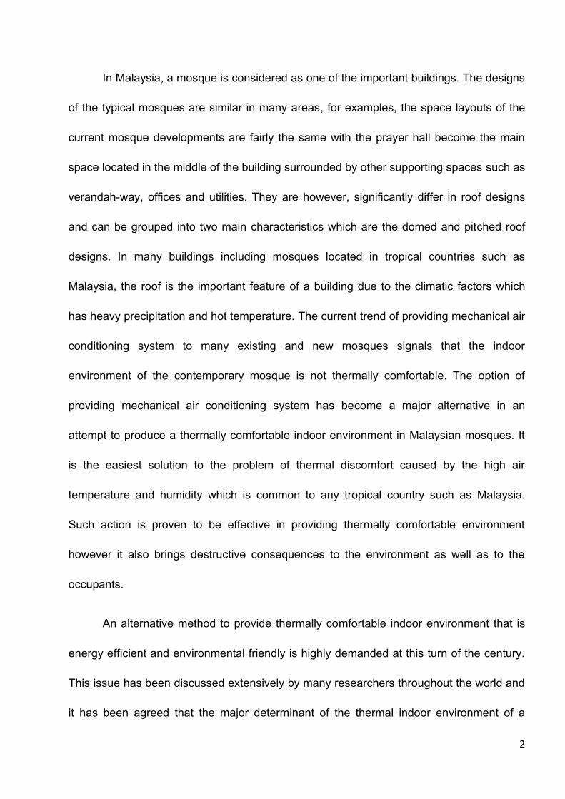
In Malaysia, a mosque is considered as one of the important buildings. The designs
of the typical mosques are similar in many areas, for examples, the space layouts of the
current mosque developments are fairly the same with the prayer hall become the main
space located in the middle of the building surrounded by other supporting spaces such as
verandah-way, offices and utilities. They are however, significantly differ in roof designs
and can be grouped into two main characteristics which are the domed and pitched roof
designs. In many buildings including mosques located in tropical countries such as
Malaysia, the roof is the important feature of a building due to the climatic factors which
has heavy precipitation and hot temperature. The current trend of providing mechanical air
conditioning system to many existing and new mosques signals that the indoor
environment of the contemporary mosque is not thermally comfortable. The option of
providing mechanical air conditioning system has become a major alternative in an
attempt to produce a thermally comfortable indoor environment in Malaysian mosques. It
is the easiest solution to the problem of thermal discomfort caused by the high air
temperature and humidity which is common to any tropical country such as Malaysia.
Such action is proven to be effective in providing thermally comfortable environment
however it also brings destructive consequences to the environment as well as to the
occupants.
An alternative method to provide thermally comfortable indoor environment that is
energy efficient and environmental friendly is highly demanded at this turn of the century.
This issue has been discussed extensively by many researchers throughout the world and
it has been agreed that the major determinant of the thermal indoor environment of a

3
building is the building design itself. The climatic influences have always been the major
issues to be considered in designing a passive building. However, the approaches
architects and designers took in designing a building has been changed parallel with the
development of the technology. Looking at the traditional or historical buildings of a certain
country, it is obvious that the environmental factors, especially the weather, has been the
main consideration in designing the building by giving careful attention to the building
envelope to shelter the users from the intolerable climatic condition. With the introduction
of the mechanical air conditioning system, this approach has been forgotten and the
climatic factors have not been considered as the main issues in the design development
process due to the capability of the system to provide the desired thermal indoor condition.
For the past few decades, researches have revealed that the use of the mechanical air
conditioning system has major disadvantages especially on the issues of pollution and
sustainability.
With this concern, numerous researches have been conducted to investigate an
alternative method to replace the cooling using the mechanical system which is proven to
be energy consuming and sometimes unhealthy. Passive design has been seen as one of
the approach that is energy efficient and environmentally friendly to achieve a comfortable
thermal indoor condition by improving the design of the building especially the building
envelope to filter the heat from the outside. Researches aiming to mitigate the transfer of
heat into the interior ranging from the determination of the indoor thermally comfortable
condition to the choices of passive design have been conducted quite extensively
throughout the world. However, the majority of the research conducted is mostly dealt with
4
the thermal comfort condition in the moderate climate countries. Only a few researches
that dealt with the thermal comfort issues in tropical countries can be found and most of
them focus on the thermal comfort condition for tropical climate on residential buildings.
Unfortunately, little knowledge can be found on the issue of thermal comfort and passive
design of mosques in the tropical countries, particularly Malaysia.
Being an important building, a mosque carries a bigger role than just
accommodating congregational prayer. It is also considered as a center for the community
where many social events relating to the disseminating of religious knowledge conducted.
Besides that, it also carries the pride of the community and depending on the types of the
mosques they also act as a landmark or monument to the country. This is not only
happening in Malaysia but also to the other Islamic countries as pointed out by Serageldin
(1990) that a mosque has been considered as an icon to portray the Islamic identity of the
country. The role of the mosque as a tool to express the spirit of solidarity and political
power among Muslim communities is also agreed by Grabar (1997). As a tool and being
an important building to the community, the mosque should also reflect the concern of
protecting and preserving the environment through its design that is environmentally
friendly. The application of the two common roof designs which are the domed roof and
the pitched roof may have contributed to the poor indoor thermal comfort condition if they
were not designed appropriately in relation to the overall design since the space layouts or
plans of the mosques are fairly similar to one another.

5
It can be evidenced in Malaysia, being one of the Islamic political government, the
architecture of the mosque especially the selection of the roof design is often copied from
Middle Eastern model. Many issues relating to the architecture of the mosque has been
discussed by architects and academicians. Mohamad Rasdi et al (2006) argue the
relevance of using the Middle Eastern, Mid Asian and African model as a reference in
Malaysian mosque architecture. He believes that the representation of Islam in
architecture should be more related to the ‘socio-economic and regionalistic concerns’
(2002). Similarly, Gregory also questions the applicability of the foreign architecture model
being implemented in Malaysia. It does not reflect the sensitivity to the culture and tropical
environment. Ismail (2008) in her research also agrees that the design of the mosque,
specifically referring to the state mosque, is more personal which is influenced by the
views of the political leaders rather than the suitability of the design to the climate and
culture. The selection of the roof designs requires many considerations especially when
dealing with thermal comfort.
It is evidenced in the previous research that the selection of the mosque design
especially on the roof design is more towards the identity rather than to the aspects
relating to the environmental physics such as thermal comfort of the building. Thermal
comfort has become an important issue nowadays as it relates to the issue of
sustainability. It does not only help to reduce the energy usage but it also helps to
improve the productivity. The increase in the number of research conducted on this field in
Malaysia recently shows the growing awareness and significance of thermal comfort in
affecting the human behavior and performance. For examples, the research by Kubota et

6
al (2009) focusing on the improving the indoor thermal condition through the use of night
ventilation techniques in terraced houses, the thermal comfort study on the schools by
Hussein and Rahman (2009) and the office comfort condition by Daghigh et al (2009)
show the effort to improve the indoor thermal condition of the important spaces involved in
the everyday life. Surprisingly, little published information can be established on the indoor
thermal condition and comfort issue on mosques despite being considered as an
important building in Malaysia.
As mentioned earlier, the majority of the mosques in Malaysia has similar plans of
space layouts but differ in the roof design application. Investigating the influence of the
roof design to the thermal condition inside a mosque and the factors affecting the thermal
comfort are crucial to ensure that the design of a new mosque can address the important
elements of the building and appropriate measures can be strategized to improve the
thermal indoor environment. By understanding the importance of each factors relating to
thermal condition and comfort, design strategies relating to the roof design can be
produced to improve the thermal comfort level of the indoor.
1.2 PURPOSE OF THE RESEARCH
The purpose of the research is to investigate the effectiveness of domed and
pitched roof design in providing thermally comfortable indoor environment in typical
naturally ventilated Malaysian mosques. The roof designs of the mosques are selected to
be studied because of their important functions; not only that the roof filters the harsh
climatic elements such as rain and heat but the roof also provides an identity to the

7
building and culture. The significant variation on the design of the mosques can also be
strongly evident more in the roof design than in the spatial layout. The research will also
focus on the issue of thermal comfort because of the uniqueness of the tropical climate of
Malaysia with high air temperature and humidity throughout the year which can make the
thermal condition of the indoor environment become very uncomfortable in most of the
time if a building was design inappropriately.
1.3 RESEARCH SCOPE
The research investigates the perception of the thermal comfort inside the prayer
halls of selected mosques to inquire the interdependency of the factors affecting thermal
comfort. However the investigation is limited to three main physical variables, namely, air
temperature, air movement and relative humidity. The selection of mosques to be studied
is based on the roof design since the majority of the mosque designs in Malaysia can be
grouped into two bigger clusters based on the roof designs. In general, there are two
distinguished characteristics of overall mosque designs in Malaysia which are the domed
and pitched roof mosques. The pitched roof mosques are considered as traditionally or
regionally influenced and the domed roof are foreign influenced. The investigation is only
conducted on the selected mosques that fall under the categories. Mosques that have roof
designs other than domed and pitched roof are not investigated in the research. Table 1.1
shows the summary of the aims, objectives and the methods of investigation involved in
the research.

8
Research Problem: The physical factors, namely air temperature, relative humidity and air movement and the roof design affecting
thermal comfort and condition in a typical naturally ventilated Malaysian mosque.
MAIN Research Question:(How) How are physical environmental factors - air temperature, relative humidity and air movement and
roof designs affected thermal comfort and condition (what) in typical naturally ventilated pitched and domed roof mosques in
Malaysia(who)?
CONSTRUCT DISCRIPTION OF Research Question
SUB-Research Question Research Objectives STRATEGY OF INQUIRY
WHAT Thermal Comfort And Condition
What is thermal comfort and factors affecting thermal comfort level of building occupants? What are the current thermal situation in a typical mosque in Malaysia
To identify the meaning of thermal comfort and factors affecting thermal comfort. To identify the current thermal situation in a mosque and the causes
Literature Review
HOW physical environmental factors - air temperature, relative humidity and air movement affecting thermal comfort
What are the relationships established by the air temperature, relative humidity and air movement in affecting thermal comfort level in naturally ventilated Malaysian mosques?
To establish a relationship between air temperature, relative humidity and air movement in influencing thermal comfort in the context of typical naturally ventilated Malaysian mosques.
Survey
HOW the mosque roof design affecting thermal condition
How thermal condition and therefore thermal comfort level is affected by the mosque roof designs in naturally ventilated pitched and domed roof mosques in Malaysia?
To analyse the influence of the design of the roof in influencing thermal comfort condition and therefore thermal comfort level in a pitched and domed roof mosque in Malaysia.
Simulation for the
roof design
WHO naturally ventilated pitched and domed roof mosque in Malaysia
What are the typical design characteristics that have been employed in designing a naturally ventilated mosque in Malaysia?
To identify typical characteristics of naturally ventilated Malaysian mosques.
Literature Review
Table 1. 1- Summary on the research questions, objectives and strategies of inquiry for the research

9
In investigating the issue, there are several objectives which need to be
achieved (refer Table 1.1). They are:
i. to identify the meaning of thermal comfort and factors affecting thermal
comfort in a tropical countries such as Malaysia.
This is achieved through literature review regarding the thermal comfort
including the definition, factors and methodology and building design
influences. It also includes thermal comfort issues focusing on the
tropical countries and Malaysia.
ii. to establish a relationship or interdependency between air temperature,
relative humidity and air movement in influencing thermal comfort in the
context of typical naturally ventilated Malaysian mosques.
This is achieved through analysis on the survey conducted at the
selected mosques. The survey inquires the thermal perception, thermal
comfort level, condition on additional comfort factors such as air
movement and relative humidity and preferences vote.
iii. to investigate the applicability of the evaluative scales currently used in
the context of naturally ventilated building for tropical climate countries.
This is achieved through the analysis from the survey collected on the
thermal perception using the ASHRAE scale and Bedford Scale.

10
iv. to analyze the influence of the design of the roof in influencing thermal
comfort condition and therefore thermal comfort level in a pitched and
domed roof mosque in Malaysia.
This is achieved using the simulation process with the aid of software
HTB2 and WinAir4 developed by Cardiff University. The data is
analyzed and compared between the pitched and domed roof. Based
on the findings, suggestions are made to improve the design in
producing thermally comfortable environment.
1.3 OUTLINE OF THE THESIS
The research starts with the introduction to issue of thermal comfort in a
typical Malaysian mosque and the possible causes of the setback encountered. It
continues with the aim and the objectives of the research and the description of the
following chapters.
It follows with Chapter Two that reviews of the previous conducted research in
thermal comfort condition particularly on the approaches of the thermal comfort study
which includes methods of data collection and evaluation for naturally ventilated
building in tropical countries. This chapter also discusses the relationship of the
building design and the climatic condition and the influence of these factors to the
thermal indoor environment.
Chapter 3 of the thesis reviews the background of the building type studied
which is a mosque. It also talks about the development of the Mosque architecture in
11
Malaysia which touches the transformation of the mosque design influenced by the
various factors happened through the time. It finally concludes the chapter by
discussing the general characteristics of the contemporary Malaysian mosque
architecture.
Chapter 4 describes the methodologies involved in conducting the research.
The discussion includes the criteria in the selection of building samples and the
participants, methods of data acquisition which are divided into qualitative and
quantitative and data analysis methods. The chapter concludes by explaining the
relevant of the methods selected.
Chapter 5 shows and analyses the result gathered from the conducted survey
and the field measurement of the air temperature and humidity in the prayer hall of
the selected mosques. Four typical mosques are selected for the purpose of the
study. For each mosque, the chapter discusses the analysis of the data from the
conducted survey on the thermal comfort condition experienced by the participants in
the selected mosques. The factors affecting the thermal comfort condition is also
discussed based on the analysis conducted. The chapter continues with the
determination of the tolerable range of the indoor thermal comfort condition and
concludes based on the analysis of the four mosques.
Chapter 6 shows and explains the results obtained from the investigation
based on the simulation using the available software. It compares the results
between the two typical mosques types which are the pitched and domed roof
12
designs. The issues that are covered include the thermal condition or air temperature
resulted from the application of the two most popular roof designs in Malaysia. The
investigation also looks at the influence of the roof design in affecting the air
movement inside the space.
Chapter 7 discusses the finding obtained from the Chapter 5 and Chapter 6
by creating linkages or relationships. Generalization based on the obtained results
regarding the thermal comfort condition of the prayer hall of the mosques selected is
made. It also proposes the scale to be used in evaluating the tolerable range of air
temperature to maintain comfort and suggests a tolerable air temperature to be
considered in the evaluation of the building regarding the thermal comfort condition.
It also suggests the guidelines in improving the design of the contemporary mosque
designs in Malaysia to improve the thermal comfort condition.
Finally, Chapter 8 concludes by summarizing the thesis and concluding the
findings from the study. The constraints and limitations of the research are pointed
out and future research is suggested.

13
CHAPTER 2 – MALAYSIA AND ITS MOSQUES
2.1 INTRODUCTION
This chapter presents an overview of Malaysia and the mosques that have been
developed in the country. The following chapter reviews the factors affecting the
thermal comfort and related researches focusing in tropical countries. This chapter
starts by introducing the background of the researched country, Malaysia which
includes the climate, population and the religion. Following that, the chapter
continues with development of the mosque architecture in Malaysia and the current
issues related to the thermal comfort and thermal condition inside the mosques.
2.2 BACKGROUND OF MALAYSIA
2.2.1 INTRODUCTION
Figure 2. 1 - Maps of Malaysia (from www.mapsofworld.com)
14
Malaysia is located in the Southeast Asia. The total area of the country is
about 329,750 kilometres square which consists of 328,550 kilometres square of
land and 1,200 kilometres square of water. It consists of two parts which are West
Malaysia and East Malaysia. West Malaysia and East Malaysia is separated by the
South China Sea. West Malaysia is a peninsular bordering Thailand at the north and
Singapore at the south; and East Malaysia, which is one third of the north part of
Borneo Island bordering Indonesia and Brunei. It is located between latitude of
0.80North and 7.50North and longitude 99.50East and 119.50East.
2.2.2 CLIMATE
Located closed to the Equator, Malaysia is experiencing a hot and humid
climate throughout the year with the average air temperature ranging from 23.7
degree to 31.30 Celsius throughout the days and the highest maximum temperature
recorded is 36.9o Celsius based on the Malaysian Meteorological Service records.
Even though the range is quite significant, the diurnal temperature range is quite
minimal. This condition has major influences to the architecture and culture of the
people. Along with this high temperature throughout the year, Malaysia also has
high content of humidity in the air. The relative humidity is between 67% and 95%
with the annual rainfall of 2,500mm which is considered heavy. Generally, the
climate can be characterized as “uniform temperature, high humidity and copious
rainfall”. Figure 2.2 shows the average temperature of Kuala Lumpur for each month.

15
Figure 2. 2 - Average temperature for Kuala Lumpur (Data taken from year 2000 to 2012 from
http://www.worldweatheronline.com/)
2.2.3 Wind Flow
The general characteristics of the wind flow in the country are relatively light and
variable. Based on the wind flow pattern, there are four seasons that are categorized
according to the direction of the flow. They are the southwest monsoon, northeast
monsoon and two shorter periods of inter-monsoon seasons (figure 2.3).
Figure 2. 3 - The monsoon seasons in Malaysia (from https://juinkadsuki.files.wordpress.com)

16
The southwest monsoon season starts in June until September with the direction of
southwesterly wind with a speed of about 15 knots which is light. The northeast
monsoon season usually commences in early November and ends in March. During
this season, the wind direction is from east or northeast at a speed between 10 to 20
knots. During this season the wind speed at the east coast of Peninsular Malaysia
may reach up to 30 knots or more. The winds during the two inter-monsoon seasons
are, however generally light and variable. The wind especially the areas closer to the
ocean can clearly be marked especially when the sky is clear. This is due to the
location of Malaysia which is surrounded by the ocean. During daytime especially in
the afternoon the sea breezes often develop and reach up to several tens of
kilometers inland. On the other hand, during night time the reverse process takes
place and land breezes of weaker strength can also develop over the coastal areas.
2.2.4 Rainfall Distribution
The rainfall distribution in Malaysia can be categorized according the rainy season
because of the seasonal wind flow and the topography of the country. The existence
of the mountain ranges in the middle of the country blocks the wind flow to arrive at
the other part of the country making the two areas having the opposite rainy season,
for examples, during the northeast monsoon season, the exposed areas like the east
coast of Peninsular Malaysia, Western Sarawak and the northeast coast of Sabah
experience heavy rain spells. On the other hand, inland areas or areas which are
sheltered by mountain ranges are relatively free from its influence.

17
There are three distinctly seasons of the rainfall in Malaysia. The east coast of
Malaysia will be experiencing a heavy rainfall in the months of November, December
and January and a dry season in the months of June and July. The west coast
especially the southwest will experience the heavy rainfall from the months of May
until August. Figure 2.4 shows the average rainfall in Kuala Lumpur, the capital city
of Malaysia.
Figure 2. 4 - The average rainfall of Kuala Lumpur (Data taken from year 2000 to 2012 from
http://www.worldweatheronline.com/)

18
2.3 POPULATION
Demographically, it has a population of 27,565,821 which comprises
14,112,667 males and 13,453,154 females. (July 2010 est.). The distribution based
on the race is Malays and other Bumiputera groups make up 65% of the population,
Chinese 26%, Indians 7.1% and other unlisted ethnic groups 1%. The Malays are
the biggest community in Malaysia as they opened the country hundreds years ago.
It started out by the opening of Melaka in 1500s by Parameswara who was originally
from Sumatera, Indonesia. Due to its strategic location, it had become a very famous
trader port. Other powerful countries saw this as an opportunity and wanted to widen
their empire by conquering the port. As a result, Malaysia, also known as Malaya
during that time, had been conquered by many countries. Britain was one of the
countries that had ruled Malaysia. During the British rule, many changes had been
made. One of the changes that had impacted the population of the country is the
migration of labours from China and India. They were brought in to help the British to
collect as much wealth from the natural resources that were plenty in Malaysia
during that time. The Chinese were brought to work at the tin mines and the Indians
were forced to work in the rubber plantation. When Malaysia received its
independent in 1957, all the migrated races had been accepted as the citizens of the
Malaysia. As for today, the Chinese is the second largest community and followed by
the Indians. The Chinese people have also become the biggest community involved
in trade and business in the country compared to other races but the Malay
community controls the politics and the administration of the country.

19
2.4 RELIGION AND CULTURE
Islam is the official religion of the country, however, the citizens are free to
practice other religions, such as, Christian, Buddhist, Daoist, Hindu, and Sikh. As the
majority of the population is Malays, the Islamic religion followers are the biggest
community in Malaysia. Islam was brought to Malaysia in the 13th century by the
Indian traders. Since then, the followers of the religion had grown tremendously. The
religion has strong influence to the culture. In Islam, rules are provided not only to a
religious ceremony but also to daily activities which include the appropriate ways to
behave in a community including the way one dressed, talked, ate, etc. As the
majority of the population practices Islam, many of other races tend to adapt to the
same norms introduced by Islam. The culture which is mostly based on Islam has
also been influenced by other traditions practiced by different races.
Each of the races has its own distinctive religious building. Being an Islamic
country, a mosque in Malaysia plays an important role in the society (Nasir, 1984;
Ali,1993). Not only it representing the official religion of the country and the
architecture of its location, but most importantly, it also brings the community
together through the congregated prayers and many gatherings conducted at the
mosque (Means, 1969). As one of the important building in the community and the
country, closer attention has been made to the architecture of the building. As a
result, the architecture of the mosque in Malaysia has gone through many steps of
development influenced by the various social aspects and environmental factors.
The current architecture styles of Malaysian mosques try to incorporate both of the

20
social and environmental factors to produce a mosque that is not only spiritually
stimulating but also communally functioning and climatically responsive.
In Malaysia, there are two famous types of mosque designs which are heavily
influenced by the roof. They are pitched roof mosque and domed roof mosque.
Complaints have been heard that some mosques are uncomfortable due to the
excessive thermal energy experienced by the users.
2.5 WHAT IS A MOSQUE?
In Islamic community a mosque is called a ‘masdjid’ derived from Arabic word
which means to ‘prostate’ (Gazalba, 1975; Asfour, 2009) which is one of the actions
during the prayer. A mosque in Islam is considered a sacred building. The
sacredness of the building, however, is more related to the function of the building
rather than the architecture. It is a place of worship to submit oneself to God
(Bosworth, 1986; Rasdi 1998). Traditionally, only religious related activities can be
conducted inside the mosque. Therefore, there are some ethics that need to be
followed when visiting the mosque which are mostly related to the dressing code and
behavioural guidelines.
2.5.1 The Elements of a Mosque
A mosque is actually started with a simple building. It is a place of worship
that has been agreed by the group or the community. The basic mosque design is
composed of three main elements; the mihrab, the minaret and the prayer space

21
(Polk, Serageldin, 1990; Holod and Khan, 1997; Frishman and Khan, 1994;Asfour,
2009). The mihrab is the one of the four walls enclosing the prayer hall that marks
the facing direction of the prayer. It is oriented toward the direction of Mecca (kibla’),
the holy city of Islam. The minaret is a tower located outside the mosque. It is used
as a place to call(azan) for the community to congregate for the prayer. It is normally
the highest structure in the community and also used as a landmark. The prayer hall
is the place where the congregational prayer and other religious activities are
conducted. It is considered the sacred place of the mosque. Among the three
elements, the prayer space is the most occupied space and accessible to the public
almost at all time during the hours of operation.
The prayer hall is normally situated at the centre of the building. It is the
biggest and hierarchically, the most dominant space among other spaces created
inside the mosque. Various methods in space arrangement have been implemented
according to the culture of a country to bring the essence of dominance and
sacredness to the prayer hall. In Ottoman architecture, the idea of arranging
secondary spaces around a primary space is common as pointed out by Jale Nejdet
Erzen(p.58). This type of configuration is important in Islamic architecture because it
expresses the importance and the sacredness of the main space by creating layers
of spaces. Layers of space, in addition to this, also create buffer zone spiritually as a
space of purifying before entering the main sacred space and technically as a barrier
‘against noise and exposure’. Similarly, Ludovico Micara believes that the use of
enclosure is the most fundamental concept in mosque architecture as it ‘delimits the

22
space and separates the place of architecture from all that is without: the urban
fabric; or the landscape and the natural world’ in an attempt to create the sacredness
of the space.
A lot of attention has been given in emphasizing the importance of the prayer
hall in a mosque. Not only the inside, the outside space of the mosque are given
careful attention in the decoration and space quality. Calligraphy and arabesque are
among the style used in decorating the spaces inside and outside the mosque. The
most common practice is to use a special roof design covering the prayer hall. A
domed roof is one of the popular roof types that have been used in mosques
throughout the world. In fact, the dome itself has been considered as one of the main
features in Islamic architecture as the dome represents the vault of heaven (Asfour,
2009). Originated from the Ottoman Turkish era in the 15th century, the central dome
mosque type has become very popular in other Islamic country. A single dominant
dome is placed at the center of the prayer hall to bring the spirit of togetherness and
openness towards God. The earlier mosque type which is originated from the
Umayyad Dynasty is called hypostyle or Arab plan mosques. This mosque type uses
columns in a large number as a support to the building. Due to its rigidness, the style
has not been very popular. The dome roof has replaced this style and has been
proven to be effective in minimizing the heat gain for this climate( Asfour, 2009;
Hameed, 2011; Hadavand et al, 2008). This condition, however, is still under
question for other climatic regions. Regardless of this, the application of dome roof
for mosque is universal.

23
Malaysia, being one of the Islamic countries, also incorporates a domed roof
as the main roof structure for many of its recent mosque developments. Its
synonymy with the Islamic architecture may have strongly influenced the universality
of its use in Malaysia and other countries. Traditionally, the pitched roof is the typical
roof design for this climatic region including Malaysia. The transformation from the
traditional pitched roof to the dome roof has taken stages of process of
developments. Besides domed roof, other types of roofs that are more modern have
also been produced such as the ‘folded-plate roof’ of Masjid Negara, Kuala Lumpur
and ‘umbrella-shaped roof of concave conoids’ of State Mosque, Negeri Sembilan.
Due to the importance of the prayer hall space and the unknown suitability of the
dome roof in providing thermally comfortable indoor environment, it is necessary to
study the influence of the dome roof into the prayer hall space in Malaysia.
The development of the mosque design in Malaysia is influenced by many
factors, socially, politically and environmentally (Ismail, 2008). The review on the
development of the mosque design in Malaysia provides information on the
influences that lead to the current mosque development.
2.6 THE DEVELOPMENT OF MALAYSIAN MOSQUE: ISLAMIC VS.
TRADITIONAL IDENTITY
Islam, as the main religion in Malaysia, places an influential factor in the
design of buildings especially Islamic religious buildings such as mosques and
‘madrasahs’. Islamic architecture being originated in the Middle East countries has
many strong elements and forms that are unfamiliar to the traditional architecture of
24
Malaysia. At certain stage in the development of mosques in Malaysia, direct
copying of forms of mosques from the Middle East can be evidenced. This eclectic
style of mosque continues for several decades in the country until Malaysia receives
her independence. The ignorance of the local identity of Malaysia in the mosque
architecture has started to create discussions among Malaysians (Dunster, Rasdi,
1998). As a result, the contemporary mosque design is expected to portray the
national identity by incorporating the traditional culture and at the same time, to show
that Islam is the major religion of the country (Vlatseas, 1990; Yeang, 1992).
The traditional architecture of Malaysia can be traced back at the dwellings of
the earliest settlement in Malaysia. The settlement started in a village called
’kampung’ whereby the people were led by a leader and normally the people were
related to each other. As they were related, issue of privacy was not a major factor
to them and this can be seen from the fenceless house and open plan houses which
allowed one area to be a multifunction area. As the society became more complex,
the element of privacy started to become more important and be considered in the
design process. New areas or spaces in the house started to be introduced which
mainly to separate between men and women. Starting with just a main house and a
kitchen, the additional spaces was later added such as the verandah and later on,
the middle house. The verandah was designed for the area of entertaining non-
relative guests and the middle house was used as a family area and the main house
was intended for entertaining relatives. The design of the traditional houses were
relatively different depending on the states they were located in Malaysia, however,

25
there are three main attributes shared by the houses which are the stilts, open plan
and pitched roof (Vlatseas, 1990).
The roof had become the main element in the traditional Malaysian
architecture. It covered bigger areas compared to other elements in a building. The
main purpose was to provide shelter from the heavy rain and shade other elements
from the direct sunlight to reduce the heat generation during the day. Additional
feature such as carved grilles was also incorporated into the design of the roof to
allow heat dissipation from the building. The roof, too, had been designed to identify
the community of the local people. Each of the state in Malaysia owned a typical
design of roof such as ‘Bumbung Lima’ for the state of Perak, Minangkabau roof for
Negeri Sembilan and high pitched roof for Kelantan and Terengganu and this design
‘distinguished the house styles from one region to the other’ (1990).
Similar ideas and concepts had been applied in other types of building as
well. The earlier designs of mosques were basically originated and followed the
traditional styles of dwellings with modification on the space layout adjusting to the
need of a mosque. However, the importance of the roof as a dominant element in
providing shelter and community identification was maintained throughout the
development of mosque design in Malaysia. The changes and variation of roof
design can be seen in the mosque development as the time changed.
Looking at the development of mosque architecture in Malaysia, the earlier
form of the mosques follows the simple Malay house form with a simple gable roof

26
using the ‘wooden house on stilts’ construction (Fee, 1998). The existing example of
this type of mosque is Masjid Kampung Laut, Kota Bharu, Kelantan (figure 2.6)
which was built two and a half centuries ago. This type of mosque was considered
the purest form of mosque design in Malaysia since the design was based on the
regional influences which can be distinguished by the use of minarets, square plan
layout and most dominantly the two or three-tiered roof (Bruce, 1996). The use of the
roof form may be duplicated from the old mosque of Indonesia as many of the Malay
Muslims are descendants of ethnic groups from Kalimantan, Acheh, Sulawesi and
Java (Ahmad, 1999; Nasir, 1995). The royal Mosque of Demak as pictured in figure
2.5 is an example of the typical traditional mosque in Indonesia.
Figure 2. 5 - Picture of The Royal Mosque Demak, Indonesia (from http://mukzizatislam.blogspot.com
With the increase contact with the outside world mostly through trades,
foreign influences started to be incorporated into the design of the mosques. Masjid
Tengkerah (1728) (Figure 2.7) and Masjid Kampung Kling (1748), both located in

27
Melaka which once was the busiest port in the world and considered the centre of
Islam for Malay Peninsula (Yahaya, 1998), displayed the strong influences of
Chinese and Indian through the addition of the brick minaret (Vlatseas, 1990).
Figure 2. 6 - Picture of Masjid Kampung Laut, Malaysia
Figure 2. 7 - Picture of Masjid Tengkerah, Melaka
(http://www.trekearth.com/gallery/Asia/Malaysia/photo173681.htm)
28
When British and Dutch occupied the country, they changed the mosque
architecture in Malaysia into a new form. The replacement of the form timber
construction was started by the Dutch (Ahmad, 1990). The traditional look of the
mosques began to change to a more modern look with the incorporation of brick
masonry and arches which had become the dominant architectural features. At the
same time, the migration of the Chinese and Indian workers which later on converted
to Islam had contributed to the influence of mosque design (Kohl, 1984). Indian
immigrants had put their influence in the mosque design by incorporating large
central space and small onion shaped dome (Vlatseas, 1990).
The design of mosque had gone another modification with the introduction of
the colonial element such as the clock tower minaret and the use of dome. The first
mosque built by the British was the Ubudiah Mosque, Kuala Kangsar in 1913 which
strongly reflects the identity of colonial building. Among the common characteristics
of the mosque which can be seen in many mosques of the same era were the
horizontal banding and onion shaped domes (Vlatseas, 1990). One of the prominent
changes made was the use of prominent size of central dome and this application
was repeatedly used in future mosque development. Masjid Zahir, Kedah (1912),
Masjid Syed Alwi, Perlis (1933) and Sultan Sulaiman Mosque, Klang (1932) are
some of the examples of mosques that applied central dome. In addition to this,
timber was no longer been used and it had been replaced by bricks, stone, cast iron
and steel (Raalah, 2002). During this period, most of the mosques build were
dedicated to the Malay sultanates to show the respect of British to the Malay rulers

29
and this had resulted in a building that is more place-like than a place of worship
(Omer, 2000; Ahmad, 1999). This is also intended to show the power of the ruling
authority at that time. Most of the mosques were designed and built by the British
architects who did not really understand the culture of the local people and the
Islamic religion. As a result, both factors had not been well incorporated into the
design. Most of the mosques of that period were referred from the design of
mosques in India and adapted with the combination of western elements (Rasdi,
2003; Hisham, 1990). This was the era where domes were first introduced in the
mosque designs in the country. This type of mosque design had prevailed through
the period of British occupation.
When the independence was gained in 1957, the needs for the new mosque
design which could reflect the country identity emerged (Vlatseas, 1990; Yeang,
1992). With the western education background, local architects were beginning to
consider incorporating traditional culture which revealed the strong sense of
rationality and functionalism into the mosque design (Yeang, 1992). Masjid Negara,
Kuala Lumpur and Masjid Negeri, Negeri Sembilan were among the designs
generated with the influence of traditional elements by the local architects after the
independence from the British. At this stage the environmental factors such as
climate and culture were still became the main priority in the design process (Soon,
1989, PETA, 1961). As the technology developed, the air conditioning system was
introduced to Malaysia. With the high temperatures and humidity during the day, the
air conditioning system seemed to work efficiently in producing comfortable

30
environment inside a building. With this latest development in technology, the design
of mosque had gone another modification. ‘The principle of orientation, natural
ventilation and implementation of sun shading seemed to become obsolete’
(Vlatseas,1990:223). The concern for the environmental effects to the building was
regarded as unimportant due to the available technology. With this notion in mind
coupled with the influence of modernist design principles, a new style of mosque
architecture appeared which tried to incorporate regeneration of Islamic architecture
element in the mosque design. As the decade changed, the importance of the
environment had become an important issue in architecture. Meetings were held at
the international level to discuss the environmental issue in relation to the
architectural industry. Rio Declaration and Kyoto Agreement were among the
important outcomes of the meetings that were greatly concerned about the issue of
sustainability (Muller, 2002). Environmental sustainability which dealt with reducing
pollution and preserving the environment and social sustainability concerning
identity, culture and tradition were among the important issues discussed. With the
realization of the importance of the environment and national identity, ‘attempts were
made to develop architectural models that were more responsive to Malaysia’s
climate and at the same time expressive of national and regional ideals’ (Vlatseas,
1990: 273).
With the increasing awareness in protecting the earth, the government of
Malaysia has started introducing schemes to promote sustainable building. Currently
the Green Building Index scheme has been introduced by the government to

31
encourage building developers and architects to produce buildings that are
sustainable. Incentives such as tax exemptions are initiated to attract the building
industries to practice green building concept by ‘increasing the efficiency of resource
use – energy, water, and materials – while reducing building impact on human health
and the environment during the building’s lifecycle, through better siting, design,
construction, operation, maintenance, and removal’ as stated in the intention of the
Green Building Index organization. The increasing number of building that that has
been awarded as green building shows that Malaysia is committed in practicing
sustainable development.
Information is essential in producing green buildings. Since the introduction of
Green Building Index in 2010, only one mosque had been awarded with the status of
green building. It can be said that the lack of knowledge or information on this type of
building may have led to the small numbers of mosque being recognized as green
building. The issue of identity of Islamic building has to be blended well with the
issue of sustainability to make the building acceptable as a green building. It can be
seen that the use of the dome as the main roof structure has been seen to prevail
with the current development. The review of the development of the mosque shows
that the incorporation of the dome and a bigger scale mosque which are different
from the traditional mosque were influenced by the need to show the power of the
rulers. In many cases the mosque models were copied from other countries. The
regional which include the social and environmental issue were not seriously being
considered in the design. In a traditional mosque, these issues were the main issues

32
affecting the design. Further studies especially on the important structure or element
of a mosque, the roof, is critically needed.
2.7 TYPICAL CHARACTERISTICS OF CONTEMPORARY MALAYSIAN
MOSQUES
Each design of a mosque in Malaysia is unique by itself, however, many of
the contemporary mosques in Malaysia shares similar characteristics such as the
space arrangement, roof design, orientation, materials and construction. These main
characteristics are applied in the majority of the mosque development in the country.
Additional features are added to inject the sense of local and traditional values into
the building. Current development on the mosque design requires the architects and
designers to promote the concept of Islam in its architecture. It can be evidenced
that the influence of the Middle-eastern mosque model is still prevailed through the
use of dominant domes (Ismail, 2008; Rasdi 2003:25)
Despite the use of dominant domes as the roof structures, many mosque
designs share similarities. A characteristic that is the same in all mosques of
Malaysia is the orientation. Direction to qiblat which is 292 degree is the most
important consideration in mosque design (Petherbridge, 1995:202). Another
similarity can be seen on the space arrangement. Space arrangement is critical in
mosque design because it directly affects the main space of the mosque which is the
prayer hall. As described earlier in this chapter, the idea of making the transition
space between the prayer hall and the outside or creating an enclosure around the
prayer hall are among the methods used to express the higher level of space
33
hierarchy and sacredness to the prayer hall. In Malaysia, this is achieved by using
the transition space by providing verandah around the prayer hall and this is derived
from the traditional architecture of Malaysia. Traditionally verandah is used as a
space to entertain guess. In mosque design, the verandah has a similar function
which is used as a place to socialize since socializing is prohibited inside the sacred
prayer hall. In addition to this, the verandah also acts as a buffer or filtration space
from the outside before entering the prayer hall. The degree of openness between
the verandah to the outside and between the verandah and the prayer hall is also
differentiated through the use of enclosure. A clear separation between the verandah
and the prayer hall can be sensed by the introduction of decorated timber panel wall
presenting the flora and fauna or geometrical pattern to compare the importance and
the sacredness of the prayer hall from the outside world.
The prayer hall encompasses the main space of the mosque. Normally, it is
square on shape and the space is oriented to the direction of Mecca (qibla’) which is
marked by the minbar. The idea of making the prayer hall as one vast central space,
as described by Le Corbusier, is one of the universal criteria of the space. This is
normally achieved through the use of an open plan with no or minimal numbers of
column. The idea of centrality is further accentuated with the application of a special
roof design.
In general, there are two types of roof, the domed and the pitched roof that
are commonly used for the mosques in Malaysia. The domed roof has been used

34
rather frequently especially in a larger scale mosque compared to the pitched roof
since it is believed to bring more spiritual values associated with Islam to the space.
Name Images Category Description Masjid Al Azim, Melaka
Pitched Roof
Officially opened in 1990. A state mosque of Melaka Can occupy up to 11, 700 people
Masjid Putra, Putrajaya
Domed roof Completed in September 1999 A state mosque Can occupy up to 10, 000 people
Masjid Tuanku Mizan, Putrajaya
Domed Roof Completed in 2009 A state mosque Can occupy up to 20, 000 people
Masjid Kariah Panchur Jaya, Negeri Sembilan
Domed roof Completed in 2007 A community mosque Can occupy up to 1000 people
Masjid At Taqwa, Paroi, Negeri Sembilan
Domed Roof Completed in 2011 A community mosque Can accommodate up to 1000 people
Table 2. 1 – Some of the development of mosques in Malaysia from year 1990 until 2011
35
Table 2. 1 shows some of the mosque developments from year 1990 until
2011. The universal acceptance of the use of dome as an indication of the building
as a mosque is perhaps one of the main reasons of the wider use of dome roof
compared to the pitched roof. Pitched roof, on the other hand, has always been
considered the traditional roof design for the country and this region due to its
capability to drain water quickly. It is also considered as one of the strongest regional
identity of the country and the surrounding area.
Rasdi (2003) disagrees with the use of dome in Malaysian mosque as the
dome is an imported characteristic of the Middle–eastern mosque. It does not reflect
the national identity. The suitability of the use of dome has been questioned in
relation to the image and identity reflected by it. Disagreement toward the use of
dome instead of pitched roof in mosque design is mainly due to the issue of identity
portrayed by these two roof designs. The study on the influence of these two roof
designs on responding to the local climate especially on the thermal comfort issue
may lead to the answer of which roof performs better in this climate. Many of the
research conducted are mainly focusing on the pitched roof concentrated on
residential buildings since the pitched roof is the most common roof type used in this
region. The application of the pitched roof design in a bigger scale building such as a
mosque is still minimal and the study on the influence of the pitched roof on thermal
condition for a bigger scale building has not been conducted extensively. Table 2.2
displays some of the traditional mosque developments that apply pitched roof in
Malaysia.

36
Name Images Category Decsription
Masjid Jamek Seremban, Negeri Sembilan
Pitched Roof
Was built in 1900 A community mosque Originally can accommodate 1000 people but after renovated it can occupy 2000 people
Masjid Kariah Kampung Jerjak,
Pitched roof
Was built in 1905 but has been renovated many times. A commun ity mosque Can occupy up to 300 people
Masjid Kariah Kampung Kuala Talang
Pitched roof
Was built in 1985 A community mosque Can occupy up to 300 people
Masjid Al Hasanah, Bangi , Selangor
Pitched with a dome
Completed in 2000 A community mosque Can occupy up to 1000 people
Table 2. 2 - Pictures of traditonal mosques applying pitched roof for the mosque.
37
2.8 CONCLUSION
The strong influence of the use of dome in Islamic architecture and in mosque
design creates conflict with the strong regional and traditional characteristics of the
pitched roof. Both of these roof designs have distinctive characteristics and
unarguably relevant to be used in a mosque design. The performance of these roof
designs in sheltering the prayer hall from the heat gain which concerned many users
may have become a valuable point in making the selection on which type of mosque
is appropriate to be used. However, little information is known on the performance of
these roofs in bigger scale buildings such as mosques and therefore more research
on the building performance is necessary to provide better understanding on how
these roofs behave in affecting the indoor thermal environment. This information may
help to improve the current design especially on the roof design since many current
mosque developments in Malaysia have similar characteristics in the major space
arrangement, orientation and construction.

38
CHAPTER 3
LITERATURE REVIEW ON THERMAL COMFORT IN TROPICS
3.1 What is Thermal Comfort?
Thermal comfort is defined as ‘that condition of mind which expresses
satisfaction with the thermal environment.’ (ASHRAE, 1992; ISO, 1994). Through
this definition, it can be implied that the thermal comfort is about the ‘condition of
mind’ or the psychological aspect of human beings resulted from the responses to
the physical environmental conditions. As it deals with the psychological aspect of
human beings, according to Parson (1995), individual differences and personal
preferences such as culture, mood and personality and other personal and
organizational factors affect the response toward the thermal comfort condition
besides the physical factors. According to Cooper (1982), thermal comfort involves
‘social constructs, which reflect the beliefs, values, expectations and aspirations of
those who construct them’ and in addition, it is also affected by environmental and
memory (Brager and deDear, 2003). Hensen defined thermal comfort as ‘a state in
which there are no driving impulse to correct the environment by the behaviour’
(2004). In general, thermal comfort can be summarized as a condition that no
changes is required to improve the condition due to the satisfaction with the current
condition that is affected by physical and psychological factors.

39
3.2 FACTORS AFFECTING THERMAL COMFORT FOR TROPICAL
COUNTRIES.
The thermal comfort factors that have become the main concern for these
regions are air temperature, relative humidity, air movement and mean radiant
temperature. These factors are also known as physical factors and they are
contributed by the nature and cannot be changed. Other factors which are called
personal factors are metabolic rates and clothing level. These factors vary from one
person to the other and can be adjusted according to the preferences of the person.
Figure 3.1 displays the influence of these factors in affecting the thermal comfort of a
human being.
Figure 3. 1 - The mechanism of thermal comfort factors affecting a human being (from
http://www.hvacairconditioningdesign.com)

40
3.2.1 Air Temperature - is also known as the dry-bulb temperature or ambient
temperature. It is the measurement of the coldness or hotness of the surrounding air
and measured with a thermometer in Celsius or Fahrenheit unit. It plays an important
role in influencing the thermal comfort level of a space because the air is the medium
that most of the heat from the environment will be transferred to the body of building
occupants. The heat from the human body will be transfer to the air when the air
temperature is cooler than human body, and similarly the heat from the air will be
transferred to the human body when the air is hotter than the human body (refer to
Figure 3.1).
Due to the significant influence of air temperature on thermal comfort, many
studies conducted are aimed to determine the comfort temperature acceptable.
ASHRAE has suggested that for a summer condition, the optimum air temperature is
24.50 Celsius which is based on the environmental climatic laboratory condition. In
this case, the influence of the outdoor air temperature has not been considered in
determining the temperature.
The indoor air temperature is heavily influenced by the outdoor temperature
for a naturally ventilated building. It is important to consider the outdoor air
temperature when determining the comfort temperature for a naturally ventilated
building. Studies have shown that the mean outdoor temperature is related to the
indoor comfort temperature experienced by the occupants (Auliciems &deDear,
1978; Brager and deDear, 1998; deDear and Auliciems, 1993; Humphreys, 1978).

41
The study by Humphreys (1978) discovered that the comfort temperatures are
linearly related to the mean outdoor temperature. The relationship derived is:
Tc = 0.534To + 11
where Tc is comfort temperature and To is mean outdoor temperature. The study of
the relationship between the mean outdoor temperature and the indoor comfort
temperature has been continued by Auliciems in 1978. By revising the results
produced by Humphreys (1978) and adding additional data from more field studies,
Auliciems proposed an equation that relates the indoor comfort temperature (Tc) to
the outdoor air temperature (To) and indoor air temperature (Ti). The equation is:
Tc = 0.48 Ti + 0.14 + To + 9.22
Nicol in his study in Pakistan (1995) has also come out with an equation that relates
the outdoor temperature and comfort temperature. The equation is:
Tc = 0.38 To + 17.0
In his recent study, Nicol (2004) has incorporated a wider range of comfort
temperature which is mostly influenced by the outdoor climate patterns that led to the
derivation of the optimum comfort temperature, Tcomf , that is based on the mean
outdoor dry bulb temperature, Ta,out . The equation is:
Tcomf = 0.31Ta,out + 17.8
The range of the temperature with the 90% acceptability is 50 and 70 Celsius for 80%
acceptability, both centred on the optimum temperature, Tcomf, aiming to discover the

42
temperature or combination of thermal variables (temperature, humidity and air
velocity) which subjects consider ‘neutral’ or ‘comfortable’. With these equations, it
shows that there is no standardized comfort temperature especially for naturally
ventilated buildings. It incorporates other influences into the thermal comfort. By
giving a range as suggested by Nicol (2004), it allows other factors especially
physical factors to be considered since these factors are always present in our
environment.
This method has been applied by Dalilah et al (2008) and Mohazabieh (2010)
in the study of assessing thermal comfort in high rise buildings in Malaysia. In the
study by Dalilah et al(2008), it is determined that the neutral temperature is 26.40
Celsius depending on the location of the buildings. However, based on the field
study, the neutral temperature produced is at 30.930 Celsius. Mohazabieh et al
(2010) predicts the neutral temperature is between 25.50 Celsius and 270 Celsius.
These results support that there is no standardized comfort temperature as it
depends on the microclimate of the place and human adaptation.
3.2.2 Air Velocity - The existence of air movement inside a space may have various
effect based on the climate and activities performed in the space. In a temperate
climate zone, the draught may be considered as a nuisance since it brings cold air
into the space especially during winter time (Oseland, 1994). For a hot and humid
area, the present of cold air is desirable due to the hot condition and high content of
humidity in the air throughout the year. With the present of air movement, the

43
process of evaporation can be speed up to provide cooling sensation. The moving
air helps to aid heat loss through the process of evaporation and convection (refer to
Figure 3.1).
Earlier studies have proofed that air velocity can increase the tolerance to air
temperature ( Xu et al, 1996; Wu, 1989; Fountain and Bauman, 199; Tanabe et
al,1987; Tanabe and Kimura, (1994). It has been suggested by DeWall (1993) that
air movement inside buildings need to be set between 0.1 -1.5 m/s to provide indoor
thermal comfort.. The study in Malaysian terraced house by Nugroho et al (2007)
discovers that the air movement available at 1m/s is not sufficient in providing
thermal comfort when the temperature is above the comfort level based on the PMV
prediction. On the other hand, a study by Md Zain et. Al (2007) found that comfort
temperature which is estimated at 28.690 Celsius for the office environment in
Malaysia has only 44% of the respondents feel comfortable when there is no air
movement but with 0.7m/s air movement, the thermal comfort can be 100%. This is
probably is caused by the different activity level conducted at both places as
emphasized by Griefahn et al (2000) that persons were less sensitive to draught
when working at an increased activity level than working at lower activity level. An air
flow that is less than 0.2m/s would not be enough while more than 2.0 m/s will create
other related problem.
Based on the findings, it can be assumed that the effectiveness of air
movement in influencing the thermal comfort level varies based on the activities

44
conducted by a person and the condition of the air temperature at a specific
situation.
3.2.3 Humidity – is usually referred as the amount of water in the form of water
vapour in a volume of air. Relative Humidity (RH) is the ratio of the amount of water
vapour contained in the volume of air to the maximum amount of water vapour that
can be held by the air at that specific temperature. The excessive presence of
humidity in the air hampers the evaporative process of the sweat produced in
reaction to the warm feeling (refer to Figure 3.1). The sweat produced is expected to
evaporate to the air to cool down the body. Without the process of evaporation, the
cooling of the body does not take place. Instead, it produces the feeling of stuffiness
which leads to thermal discomfort. In a country with a moderate climate, this problem
may not be considered critical due to the low air temperature throughout most of the
year. The effect of the humidity may not be felt because the body does not release
as much sweat due to the cold air. However, the humidity content has become a
major concern in providing thermal comfort for the hot and humid countries due to
the high air temperature throughout the year. Sweating is inevitable in this country
because of the high air temperature. This condition becomes worse because the
content of humidity in the air for this country is also high and this slower down the
process of evaporation. Dehumidification is the only way to reduce the thermal
discomfort caused by humidity and this can be achieved through sufficient air flow
(Nugroho et al, 2007)

45
3.2.4 Radiant Temperature - The Radiant Temperature is often described as the
temperature received from the radiating heat of the surfaces enclosing a space. The
Mean Radiant Temperature (MRT) is the average temperature of the surfaces
around a cubical space and it can be measured using the globe thermometer. For
the moderate climate, a difference of 1 degree Celsius between the ambient air
temperature and MRT is desirable because of the higher heat generated by the
surfaces helps the body to keep warm. For the hot and humid climate, lower MRT is
more desirable because it can absorb the heat from the air to provide a cooler
environment. Cooler surfaces around a human body helps the radiation of body heat
to a cooler surface too (refer Figure 3.1) releasing heat energy to make the person
feeling cooler.
3.2.5 Clothing Insulation – is referred to the amount of layering of clothing worn. It is
ranged from 0 (naked) to 1 (heavily clothed). Table 3. 1 shows the examples of the
Table 3. 1 - The examples of clothing value for the clothing items (from http://www.esru.strath.ac.uk/)
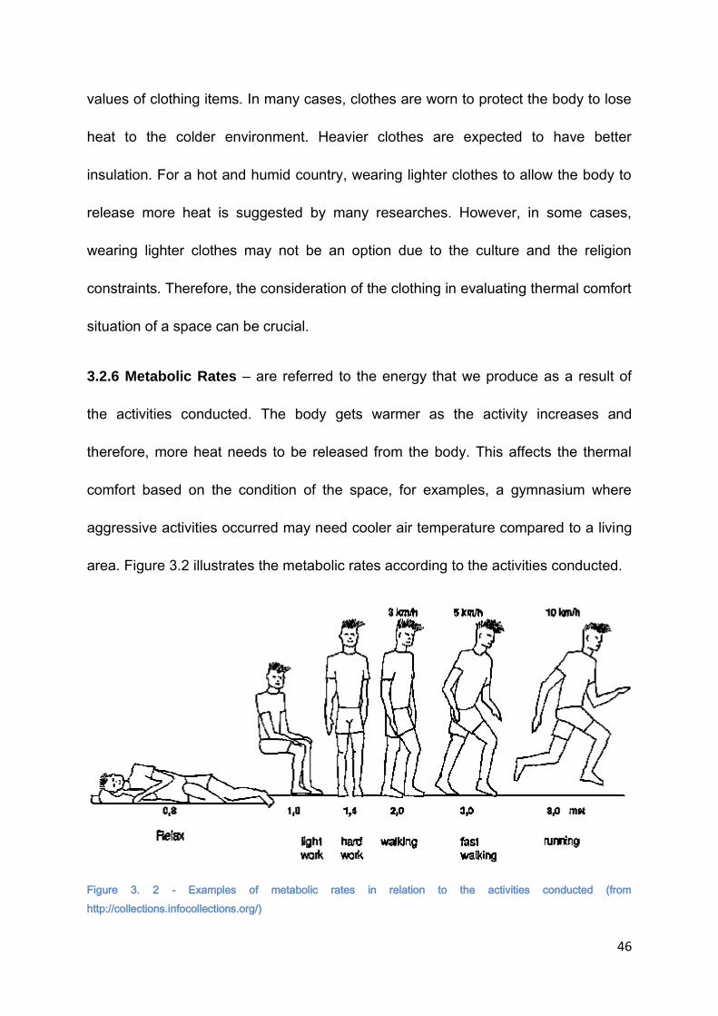
46
values of clothing items. In many cases, clothes are worn to protect the body to lose
heat to the colder environment. Heavier clothes are expected to have better
insulation. For a hot and humid country, wearing lighter clothes to allow the body to
release more heat is suggested by many researches. However, in some cases,
wearing lighter clothes may not be an option due to the culture and the religion
constraints. Therefore, the consideration of the clothing in evaluating thermal comfort
situation of a space can be crucial.
3.2.6 Metabolic Rates – are referred to the energy that we produce as a result of
the activities conducted. The body gets warmer as the activity increases and
therefore, more heat needs to be released from the body. This affects the thermal
comfort based on the condition of the space, for examples, a gymnasium where
aggressive activities occurred may need cooler air temperature compared to a living
area. Figure 3.2 illustrates the metabolic rates according to the activities conducted.
Figure 3. 2 - Examples of metabolic rates in relation to the activities conducted (from
http://collections.infocollections.org/)

47
Based on the research conducted earlier, it seems that air temperature is the
most important element in affecting thermal comfort level. Other factors seem to
contribute to the thermal comfort level either by improving or worsening the thermal
comfort situation depending on the situation. Many of the earlier research seemed to
consider these factors as a joint factor which means that these factors are always
giving an impact regardless of the situation. Due to the variation on the results
established from the earlier research, some of the factors may not act as a joint
factor but rather a contributing factor that can be ignored at certain situation.
3.3 THERMAL COMFORT IN TROPICAL COUNTRIES
The issue of thermal comfort has long been discussed by many architects and
academicians. In the tropical countries, the issue of achieving thermally comfortable
condition is focused on the cooling of the indoor environment (Karyono, 1993;
Busch, 1990; deDear, Leow and Foo, 1991;Wong, 2003; Hussein and Rahman,
2009)). Generally, the average air temperature for this region is within the range of
26 degree Celsius to 30 degree Celsius and with this range of temperatures, the
indoor condition will be under the uncomfortable category based on the
psychrometric chart. For a free running building located in this region, achieving a
suggested comfortable air temperature according to the available standards could be
difficult since the indoor climate condition of the building is heavily dependent on the
outdoor climate. In addition to this, there are other factors such as relative humidity,
air movement and clothing that are equally significant in influencing the thermal
comfort level for this climatic region.
48
The thermal comfort is considered as the most important aspect in indoor
environmental quality as building occupants are very sensitive to the operative
temperatures compared with the other three parameters’ of indoor environmental
quality which are the indoor air quality, noise level and illumination level. It does not
only affect the behaviour of occupants but it also influences the building performance
in terms of its practicality and energy efficiency (Yao et al, 2009).
Extensive research on the issue of thermal comfort has been done in the last
50 years especially in the temperate climate which is more focused on the heating of
the building. As the awareness grows, the research has been expanded to other
climatic regions with hotter climate such as the tropics including the hot and humid
area such as Malaysia, Indonesia, Singapore and Indonesia.
The hot and humid areas are generally located close to the equator. The
climate of these countries as an overall is fairly the same, however with the location
and geographical condition of the countries, each country has its own unique
climate. The earliest investigation was conducted by Webb in 1949 which led to the
derivation of the Equatorial Climate Index (ECI). Based on the index, the ideal air
velocity is 0.2 m/s with the relative humidity of 70% and the ideal temperature of
28.860 Celsius. However, the prediction is only based on the dry and wet bulb
temperature and wind speed but excluded activity level and clothing value in the
derivation. The study involved a small number of participants which may not

49
represent the majority of the community. The study should involve bigger
representation of the community.
In 1952, a study by Ellis in Singapore concludes that European men and
women that have gone acclimatization process have similar thermal comfort level
with the Asian men and women. The study involves 34 Europeans and 100 Asians.
Race, gender and sex have insignificant influences on thermal comfort.
Another study was conducted in 1978 which corrected the optimum ideal
temperature to 26.4o Celsius. The study was conducted at the hawker centres in
Singapore and found that the thermal comfort condition is affected by the
combination effects of air temperature, relative humidity and roof thermal radiation
(Rao and Ho, 1978).
In 1990, Busch conducted a study on offices in Bangkok , Thailand. The
neutral temperature or effective temperature for the air conditioned buildings and
naturally ventilated building is 24.54o Celsius and 28.54o Celsius.
Mallick(1996) in his investigation had also discovered that people are highly
adaptive to the surrounding environment by changing the behavioural patterns and
lifestyle preferences. The process of acclimatization also had a strong influence in
the comfort preferences study. In his 1996 study involving a group of architectural
students living in urban housing in Dhaka, Bangladesh, Mallick discovered that the
participants were able to tolerate high relative humidity and temperature for comfort
mainly due to the adaptation to the specific climate. The study also found that the

50
estimated comfort temperature was between the range of 240 Celsius and 320
Celsius with the relative humidity between 50% and 90% under still-air condition and
with the movement of air at 0.3 m/s, the range increased by 2.4 0 Celsius for the
lower count and 2.20 Celsius for the upper limit. The air movement was a contributing
factor in providing thermal comfort environment, on the other hand, according to this
study, despite a wide range of recorded relative humidity which ranged from 50% to
95%, the humidity had little influence to the thermal comfort level due to the long
term conditioning even though there is a decrease in comfort temperature when the
humidity is higher (Mallick, 1996).
Singapore and Indonesia are among the countries in Southeast Asia that are
actively conducting research in the thermal comfort issues. For examples, in 2003,
Wong and Khoo conducted a thermal comfort study in naturally ventilated
classrooms in Singapore. The study discovered that the neutral temperature derived
from the TSV is 28.80Celsius. Earlier studies conducted by Busch in Thailand and
deDear et al in Singapore have also found that 28.50 Celsius is the neutral
temperature for a naturally ventilated building. The readings obtained are quite close
for the neutral temperature in the similar climate region. On the other hand, the PMV
based on Fanger’s equation and the ASHRAE standard 55-92 were found to be
inapplicable in the study of thermal comfort for the area of hot-humid climate.
ASHRAE Standard 55 predicted comfort temperature is far lower than the actual
comfort temperature based on the field study. The Fanger’s PMV model similarly
shows discrepancy by being higher at lower temperature (Wong et al). The study by
51
Wong et al in 2002 in naturally ventilated public housing in Singapore also revealed
that thermal perception of +2 and +3 is still considered comfortable. Similar to the
finding by Mallick’s, the study also found that there is a strong correlation between
the thermal comfort perception and wind sensation.
In 2004, Feriadi and Wong conducted an investigation regarding the thermal
comfort perception, evaluation of the thermal comfort prediction and the behavioural
action that influence thermal comfort perception in naturally ventilated houses in
Indonesia. The study concluded that the prediction using the ASHRAE and Bedford
Scale is irrelevant in predicting the thermal comfort condition for tropical climate. The
finding also suggested that adaptive behaviour may influence the neutral
temperature to be higher than it was supposed to, however, cooler temperature is
still preferable, if possible. Earlier, Karyono conducted a field study on the thermal
comfort, which samples are divided into various categories and groups, for a multi
storey office building in Jakarta, Indonesia. The groups are categorized by gender,
age, ethnic background and physical characteristics. The study concluded that it is
statistically insignificant between the neutral temperature between male and female,
subjects under 40 and over 40 years old and between different ethnic backgrounds
as well as between thin and normal subjects. The study also revealed that the
neutral temperature is increased in the late afternoon compared to the early morning
by 30 Celsius.

52
The majority of the research conducted in tropical countries focuses on
predicting the thermal comfort based on the neutral or comfort temperature for
specific building types which include residential, offices and schools. In many cases
the evaluated comfort temperature agrees with other research and falls within the
acceptable range. However, the use of PMV has been found to be inaccurate in
predicting thermal comfort for this region when compared with the actual thermal
sensation vote (TSV). The subjective scale which is the ASHRAE and Bedford scale
applied may have been interpreted differently by the locals. Besides the PMV
equation, the applicability of the thermal sensation scale and Bedford scale in
evaluating thermal comfort condition for this region is yet to be studied.
The previous research has investigated three main physical variables that
have been the main concern of the research which are air temperature, relative
humidity and air movement. They have been proven to tremendously affect the
thermal comfort level. However, the interdependent of the variables in influencing
thermal comfort for this region has not been investigated.
3.4 THERMAL COMFORT STUDIES IN MALAYSIA
The number of studies on the determination of the acceptable thermal comfort
level for naturally ventilated buildings in Malaysia has increased in recent years. The
knowledge on the issue is important as it provides references in providing thermally
comfortable indoor environment that can save the usage of energy. Among the
studies are discussed below. Table 3.2 summarizes the studies that have been
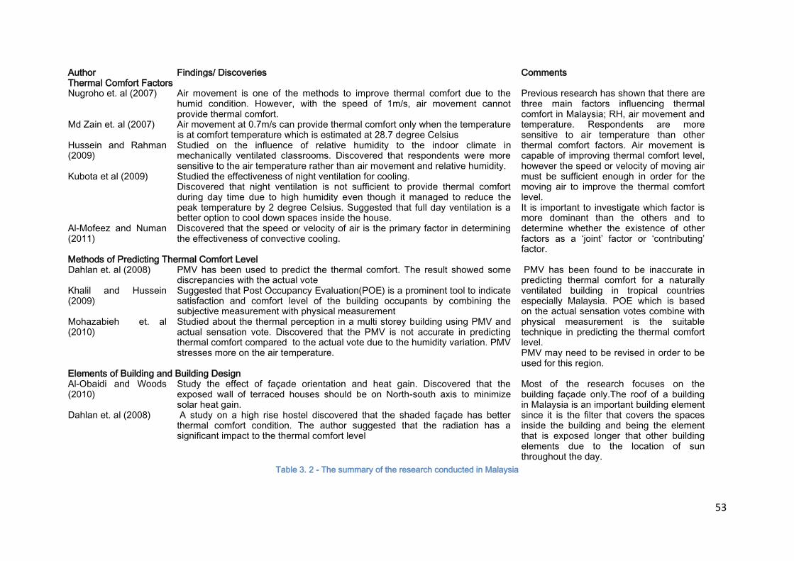
53
Author Findings/ Discoveries Comments Thermal Comfort Factors Nugroho et. al (2007) Air movement is one of the methods to improve thermal comfort due to the
humid condition. However, with the speed of 1m/s, air movement cannot provide thermal comfort.
Previous research has shown that there are three main factors influencing thermal comfort in Malaysia; RH, air movement and temperature. Respondents are more sensitive to air temperature than other thermal comfort factors. Air movement is capable of improving thermal comfort level, however the speed or velocity of moving air must be sufficient enough in order for the moving air to improve the thermal comfort level. It is important to investigate which factor is more dominant than the others and to determine whether the existence of other factors as a ‘joint’ factor or ‘contributing’ factor.
Md Zain et. al (2007) Air movement at 0.7m/s can provide thermal comfort only when the temperature is at comfort temperature which is estimated at 28.7 degree Celsius
Hussein and Rahman (2009)
Studied on the influence of relative humidity to the indoor climate in mechanically ventilated classrooms. Discovered that respondents were more sensitive to the air temperature rather than air movement and relative humidity.
Kubota et al (2009) Studied the effectiveness of night ventilation for cooling. Discovered that night ventilation is not sufficient to provide thermal comfort during day time due to high humidity even though it managed to reduce the peak temperature by 2 degree Celsius. Suggested that full day ventilation is a better option to cool down spaces inside the house.
Al-Mofeez and Numan (2011)
Discovered that the speed or velocity of air is the primary factor in determining the effectiveness of convective cooling.
Methods of Predicting Thermal Comfort Level Dahlan et. al (2008) PMV has been used to predict the thermal comfort. The result showed some
discrepancies with the actual vote PMV has been found to be inaccurate in predicting thermal comfort for a naturally ventilated building in tropical countries especially Malaysia. POE which is based on the actual sensation votes combine with physical measurement is the suitable technique in predicting the thermal comfort level. PMV may need to be revised in order to be used for this region.
Khalil and Hussein (2009)
Suggested that Post Occupancy Evaluation(POE) is a prominent tool to indicate satisfaction and comfort level of the building occupants by combining the subjective measurement with physical measurement
Mohazabieh et. al (2010)
Studied about the thermal perception in a multi storey building using PMV and actual sensation vote. Discovered that the PMV is not accurate in predicting thermal comfort compared to the actual vote due to the humidity variation. PMV stresses more on the air temperature.
Elements of Building and Building Design Al-Obaidi and Woods (2010)
Study the effect of façade orientation and heat gain. Discovered that the exposed wall of terraced houses should be on North-south axis to minimize solar heat gain.
Most of the research focuses on the building façade only.The roof of a building in Malaysia is an important building element since it is the filter that covers the spaces inside the building and being the element that is exposed longer that other building elements due to the location of sun throughout the day.
Dahlan et. al (2008) A study on a high rise hostel discovered that the shaded façade has better thermal comfort condition. The author suggested that the radiation has a significant impact to the thermal comfort level
Table 3. 2 - The summary of the research conducted in Malaysia
54
conducted in Malaysia focusing on the issues of thermal comfort and building
designs.
Nugroho et al (2007) investigates the thermal environment and comfort
condition of a terraced house in Malaysia based on field measurement and
simulation. The authors study the influence of air movement on thermal comfort level
based on the climatic condition of Malaysia and discover that the air movement
available at 1m/s is not sufficient in providing thermal comfort. The PMV is used in
predicting the thermal comfort condition and produces the result that the thermal
comfort condition is uncomfortable at most of the time. The author agrees that air
movement is one of the methods to improve the thermal comfort level due to the
humid condition. However the level of importance between the air temperature, air
movement and humidity in affecting thermal comfort level has not been discussed.
Md Zain et al (2007) explore the possible means and ways of improving and
increasing the effectiveness of energy efficiency strategies of buildings in Malaysia
through the influence of air movement in bringing thermally comfortable indoor
environment. They discover that the air movement of 0.7 m/s is efficient in providing
thermally comfortable environment only at comfort temperature. The comfort
temperature is estimated at 28.69 0C.This shows that the influence of air movement
in improving thermal comfort level varies depending on the condition of other factors
of thermal comfort. Other factors may have greater significance in affecting thermal
comfort depending on the condition of other influencing factors. The factors should
55
be seen as interrelated with one another. With the knowledge of thermal comfort
behavior of human, energy utilization and behavior of buildings, the strategies can be
produced to improve the indoor thermal condition and energy usage.
Dahlan et al (2008) conduct an investigation on thermal comfort condition of
high rise hostels in Malaysia with a variation on the façade condition and find out that
the shaded façade has better thermal comfort condition. The authors have
suggested that the radiation has a significant impact to the thermal comfort level.
The PMV has been used to predict the thermal comfort condition and the result
shows some discrepancies with the actual vote. In this investigation, the authors
have considered other thermal comfort factors in predicting thermal comfort level.
However the interdependence of the thermal comfort factors has not been
investigated.
In 2009, Hussein and Rahman study the influence of relative humidity to the
indoor climate in mechanically ventilated classrooms in Malaysia and the accepted
level of indoor thermal comfort based on the subjective responses. The neutral
temperature established from the study based on the PMV regression is 25.90C with
a comfort range of 24.40C and 27.40C and based on TSV regression is 28.40C with
the acceptable range of 26.00C to 30.70C.The study reveals that the respondents are
more sensitive to the temperature(thermal sensation) compared to the relative
humidity and air movement. However, the investigation has not shown when air
movement and relative humidity becomes significant in affecting thermal comfort.
56
The importance of air movement and relative humidity should be investigated as they
are important elements in affecting thermal comfort for this region.
Kubota et al (2009) study the use of night ventilation for cooling purposes in
residential building which is a terraced house. The study has found that the night
ventilation has reduced the peak temperature by 20C but it is not sufficient in
providing daytime thermal comfort due to the high humidity conditions. It is
suggested that full day ventilation is a better option to cool down the spaces inside
the house. This finding suggests the interdependence of the physical factor of
thermal comfort is important in evaluating thermal comfort.
Khalil and Husin (2009) states that the post occupancy evaluation (POE) is a
prominent tool that able to indicate satisfaction and comfort level needs by building
occupants as lessons learned to identify problems in indoor environment. By using
the occupants as the benchmark of evaluation, the results reflect the actual
occupants’ perceived comfort and productivity levels. Therefore, the use of
subjective measurement combined with physical measurement should be
encouraged in evaluating an existing and occupied building.
Mohazabieh et al (2010) study the perception of non-Malaysian residents on
thermal comfort condition in a multi storey residential building using the PMV and
actual thermal sensation vote. The PMV is found to be inaccurate in predicting the
thermal comfort condition when compared to the actual thermal sensation vote. The
authors indicate that the difference in the PMV vote is due to the humidity variations

57
and the PMV only stresses on the air temperature. They also emphasizes that the
importance of other variables varies with the region but the issue has not been
discussed in the research. The neutral temperature is between 26.50 Celsius – 27.00
Celsius.
Al-Obaidi and Woods (2010) conduct an investigation on the orientation effect
on the indoor thermal condition in terraced houses. The study focuses on the
orientation of the façade and they conclude that the exposed walls of the terrace
houses should be on the North-South axis to minimize solar heat gain. Other building
elements such as the roof and floor have not been covered in the research.
Al-Mofeez and Numan (2011) study the effectiveness of wall-mounted
oscillating fan in providing thermal comfort which can reduce energy consumption.
The study discovers that the combination of AC and oscillating fan can reduce the
energy by increasing the set temperature of thermostat. At 0.6 m/s the temperature
set for the thermostat is 27.840C. They conclude that air velocity is a primary factor
which determines convective cooling and thus directly influences the corresponding
air temperature for human thermal comfort.
It has been evidenced from the review that most of the building studied
focuses on the residential buildings especially terraced houses in Malaysia( Dalilah
et al, 2008; Kubota et al, 2009; Al-Obaidi and Woods, 2010; Mohazabieh et al, 2010,
Nugroho et al, 2007). Public buildings except schools (Hussein and Rahman,
2009;Rahman and Kannan, 1996) that has bigger single spaces such as community
58
halls and mosques which are important buildings in the community have not been
covered in the research. The study on the public buildings that are important to the
community such as mosques should be carried out.
In addition to this, many of the research are focussed on the determination of
acceptable thermal comfort range by comparing between the results obtained by the
PMV and actual votes of the respondents. The PMV has been proven to be
inaccurate in predicting the thermal comfort condition(Dalilah et al, 2008;
Mohazabieh et al, 2010; Hussein and Rahman, 2009). The comfort temperature
obtained based on the actual votes varies based on the building design and location
however it falls within the range of 80% of the acceptability rates when compared
with the results from earlier research conducted in the other hot and humid countries
such as Singapore, Indonesia and Thailand. The use of actual votes should be
encouraged when deals with existing and occupied building as mentioned by Kalil
and Husin.
The previous research has also looked at the influence of the physical factors
such as air temperature, relative humidity and air movement in affecting thermal
comfort condition in naturally ventilated buildings. For example, the air movement
plays an important role in aiding building occupants to improve thermal comfort
condition depending on the air temperature and humidity content in the air(Md Zain
et al, 2007; NUgroho et al, 2007;). With high relative humidity, air movement may not
be enough to provide thermally comfortable environment (Hussein and Rahman,
59
2009; Mohazabieh et al, 2010;Kubota et al, 2009). These factors have been proven
to be contributors to the determination of thermal comfort. However, most of the
research considers the influence of each factor in relation to thermal comfort. They
are interrelated and how the factors work as an interdependent group has not been
investigated.
In general there is a gap on the interdependency of the physical factors in
affecting thermal comfort in naturally ventilated buildings especially in mosques. The
building element that has been investigated is focussed on the façade. The
knowledge on the influence of the roof in contributing to the determination of thermal
comfort level is still lacking.
3.5 EVALUATIVE METHODS IN THERMAL COMFORT
There are two types of thermal comfort models that have been applied in
assessing thermal comfort. The first model is based on the static or controlled lab
environment and the second model is based on the adaptive method which is based
on the field study investigation.
3.5.1 Static / controlled lab studies
The model was developed by Fanger in 1970 which is known as
Fanger’s Predicted Mean Vote (PMV). By using data from other researchers’
studies (McNall, Jaax, Rohles, Nevins and Springer, 1967) and his study
(1967), Fanger has developed a comfort equation which combined the six
variables affecting thermal comfort. He later expanded the comfort equation

60
which is known as PMV index. This index also relates the thermal condition to
the ASHRAE thermal sensation scale. Prediction on thermal comfort condition
using the PMV index or Fanger’s comfort equation needs the measured sum
of the related temperatures and variables. The predicted comfort temperature
in many indoor settings is 25.6oCelsius. According to ASHRAE, the
acceptable thermal environment is achieved when 80% of the occupants
accept the environment as thermally comfortable.
With the PMV index, thermal comfort standard is setup. ASHRAE
Standard 55 (ASHRAE, 1992) which is derived from the PMV has suggested
the optimum temperature for the winter is 22o Celsius with the acceptable
range between 20-23o Celsius. Whereas, for the summer, the optimum
temperature suggested is 24.5o Celsius with the comfortable range between
23-26o Celsius. This summer range is applicable when the activity level is 1.2
met, relative humidity at 50%, air flow is less than 0.15m/s and clo. level is
0.5.
3.5.2 Adaptive studies
The adaptive approach is based on the findings from field studies
conducted involving survey and field measurement of the thermal comfort
variables investigated (Nicol and Humphreys, 2002). In this approach, the real
experience of thermal comfort from the users is recorded using the descriptive
scale such as ASHRAE or Bedford scale. The data is then analyzed and used

61
to predict the ‘comfort temperature’ or ‘comfort condition’ (Nicol and
Humphreys, 2002).
Both of these models approach the issue of thermal comfort in a different
perspective. The static or closed lab experiment is based on the thermoregulation
and heat balance theories (Charles, 2003). With these theories, the thermal comfort
variables studied can be controlled and the responses can be monitored accordingly.
The focus of the study is more toward the quantifiable aspect of the thermal comfort
variables. The adaptive model sees thermal comfort as an experience influenced not
only by the quantifiable thermal comfort variables but also the psychological and
social factors. It involves the actual users and environment in predicting the actual
thermal comfort perception. Each of the models has its own advantages and
disadvantages. Depending on the scope and context of the research, the appropriate
model can be determined. The following section reviews the applicability of the
models in predicting thermal comfort.
3.6 APPLICABILITY OF THE THERMAL COMFORT MODELS
2.2.1 Fanger’s Predicted Mean Vote (PMV) model
Fanger’s Predicted Mean Vote (PMV) model has been applied in many
thermal comfort researches since it was established in 1970. Charles in her 2003
report has reviewed the applicability of the model in predicting thermal comfort
condition based on the studies conducted by earlier researchers. She concludes that
the applicability of PMV model in field study settings does not accurately reflect the
actual thermal sensation and in many cases, the PMV predicts the thermal comfort
62
condition more accurately in air-conditioned buildings than naturally ventilated
buildings.
It is quite apparent that there is a lot of discrepancies between the results
obtained from the PMV and the actual thermal sensation on naturally ventilated
buildings. The studies by Oseland (1996), Busch (1990) and deDear et al (1991)
confirmed that the PMV model has bigger discrepancies in predicting thermal
comfort in naturally ventilated building ranging from 2.80 Celsius to 3.60 Celsius.
The use of PMV requires accurate data input of the measured variables. The
PMV model considers six thermal comfort variables which are air temperature, mean
radiant temperature, relative humidity, air movement, clothing level and metabolic
rate. As mentioned by Fanger (1994) that inaccurate data leads to ‘poor prediction’, it
is critical to provide accurate data of these variables to accurately predict the thermal
comfort condition. Most of the inaccuracy is resulted from the clothing value and
metabolism rate (Charles, 2003). Research done in tropical countries especially in
naturally ventilated buildings has indicated the inaccuracy of PMV in evaluating
thermal comfort for this region. Djongyang and Njormo also believe that despite the
widely used and compatible ASHRAE standards, a ‘different level of comfort
parameters’ is required for different climatic region such as the tropics (2010).
2.2.2 Adapative Thermal Comfort model
The adaptive thermal comfort model is introduced as an alternative in
predicting thermal comfort condition after the realization of factors affecting thermal
63
comfort includes ‘contextual factors and past thermal history’ (deDear and Brager,
1998) and it is not only based on the physical environmental factors. With this
realization, the increasing number of study involving field survey has been conducted
in different countries and building types to investigate the parameters affecting the
thermal comfort. A field study has the advantage of recording the actual thermal
sensation and comfort experienced by the users. As mentioned by Gossauer and
Wagner (2007), ‘field studies consider the whole indoor environment of the surveyed
people’ and with the information, the building occupants’ perception on the thermal
environment generated by a building type can be studied. Kuchen and Fisch(2009)
also agree that the feedback from ‘subjects’ diagnosis’ is an important tool in
evaluating thermal comfort condition.
There are three class of thermal comfort studies as described by Brager and
deDear (1998). They are:
a. Class l – The study allows a careful investigation on a building. The equipment
used must be in accordance with the specifications stated by the ASHRAE 55
(ASHRAE, 2004) and ISO 7730. The measurement requires laboratory grade
instrumentation with at least three reading at different height.
b. Class ll- The procedure can be used in studying the behavioral adjustment and
control on subjective responses. In this procedure, the measurement of the
variables needed to calculate the PMV and PPD is taken at the same time and
place where the questionnaire survey is conducted.

64
c. Class lll – This is the simplest procedure which involves the indoor air
temperature and probably relative humidity. The measurement of the physical
variables does not have to be simultaneously.
The descriptive or rating scale that is used in recording thermal sensation is
based on the ASHRAE thermal sensation scale which employs seven scales. The
ASHRAE thermal sensation scale is referring only to the thermal sensation as
thermal comfort involves other influencing factors. Therefore, it is assumed that a
thermally comfortable condition is achieved when there is no thermal sensation
present or at neutral level. Another rating scale that is quite frequently used is
Bedford scale. Similar to the ASHRAE Thermal Sensation scale, it has seven
thermal sensation scales. However, it differs in the description of each scale. For
examples, the ‘neutral’ thermal sensation under the ASHRAE is described as
‘comfortable’ under the Bedford scale. The ‘warm’ and ‘cool’ scales are described as
‘comfortably warm’ and ‘comfortably cool’. The inclusion of the term ‘comfortable’ in
explaining the scale may have different perception since the meaning of comfortable
involves not only thermal sensation but other aspects as well. The ASHRAE scale,
on the other hand, is precisely describing the thermal sensation. Therefore, even
though the two thermal sensation scales are almost the same, the results obtained
may differ due to the perceptions. It is interesting to see the perception of Malaysians
who experienced hot and humid climate in responding to the two scales as they may
interpret the description differently.

65
It is obvious that the use of PMV in predicting thermal comfort condition is
useful when the availability of the building occupants is limited. The use of the PMV
needs accurate measurement and it is more suitable for a building with a controlled
environment. For an occupied free-running building, a field study using adaptive
thermal comfort model is more appropriate since the actual result can be obtained
from the users’ of the building.
3.7 CONCLUSION
Thermal comfort for the tropical countries has become an important issue
since the standards established are more applicable to the moderate climate
countries. As a result, the PMV which is based on the closed lab environment is
inaccurate in predicting the thermal comfort level when compared with the actual
vote from the users especially in naturally ventilated buildings in tropical climate. As
the indoor climate is heavily dependent on the outdoor climate condition, the
interdependence of the physical factors which are the air temperature, relative
humidity and air movement may have play an important role in affecting thermal
comfort. The influence of each single factor to thermal comfort has been studied by
earlier researcher. However, the significant of each variable in conjunction with other
variables has not been investigated. In addition to this the application of subjective
measurement using ASHRAE thermal sensation scale or Bedford scale may have
contributed to the inaccuracy of the results obtained from the respondents due to the
different interpretation of the descriptive sensation. This is still to be discovered.
66
In terms of building design, many of the research conducted focus on the
influence of façade to the thermal condition. Many buildings in the tropical countries
put a bigger role on the roof element to protect the interior from the harsh climate.
Little information is known on how the roof behaves in influencing the thermal
condition and therefore the comfort level of the space it covers. Many of the
conducted investigation focused on the spaces that were occupied for a long time
with varied activities such as spaces inside a house or an office. In a mosque, the
occupants are normally stayed for no longer than one hour and therefore, the
expectation on the thermal comfort condition may not be the same with other
spaces. In addition to that, the restriction on the activities that can be conducted and
clothing regulations or ethics in a mosque may have influenced the perception on the
thermal comfort. The investigation on the comfort culture on a mosque will try to
discover the answer.

67
CHAPTER 4 - METHODOLOGY
4.1 INTRODUCTION
Chapter 4 introduces the methodology applied in conducting the research
which covers the topics of the selection of building samples and participants, data
acquisition and data analysis methods. The previous chapter describes the building
typology studied and the development of the local architecture of Malaysia focusing
on the mosques. This chapter starts with the introduction on the two distinguished
methods designed for this study. The first method is the field study involving survey
using questionnaires and field measurement. This chapter explains the process
involved in conducting the field study including the execution of the survey and field
measurement during the data collection process. The chapter then continues with
the explanation of the analysis process. Following this, the chapter briefly describes
the second method involved in the study which is based on the computer modeling.
It includes a brief introduction on the software used which is HTB2 and WinAir4. It
also explains the investigative process involved in the study. Finally, the chapter
concludes by justifying the relevance of the method chosen in conducting the
research. The flow of the research is shown in Figure 4.1.

68
Figure 4. 1 -Flow chart of the research process
Introduction
Literature Review
Introduction of Malaysia location, geography, climate, people and culture Introduction to the mosque architecture in Malaysia and the
Factors Affecting Thermal Comfort in Tropics
Background of Malaysia Building Typology
Thermal Comfort in Tropics
Research Methodology
Post Occupancy Evaluation Survey and Field Measurement
Computer Modeling - Simulation
To inquire the thermal comfort perception among the mosque users To investigate the significant factors in affecting thermal comfort for building in tropics
To investigate and compare the performance between the pitched and dome roof mosque in influencing indoor thermal condition
Data Analysis and Discussion
Synthesis of the results obtained from both discussion
Data Analysis and Discussion
CONCLUSION

69
4.2 BACKGROUND
Conducting a study on a specialized building such as a mosque requires
careful procedures. It is important to determine appropriate approaches to be applied
in carrying the study since the building carries some sensitivity issues that relate
directly to a religious practice and spiritual aspect of people lives. There are
constraints that need to be considered in conducting the research. For examples,
various aspects related to the adaptive behaviour including variables such as
clothing, metabolic rates and air movement preference may have enormously
affected the decision of the thermal comfort evaluation. These variables are difficult
to measure and generalize since these variables are unique and personal. In
addition to this, being a public building that is accessible as early as 5.00 am until
10.00 pm, it is difficult to have a controlled environment for the study. The conducted
research must not interrupt the daily activities conducted in the mosques and must
follow all the rules and regulation stated by the mosque authorities which is normally
related to the Islamic religion.
With these issues in mind, it is apparent that the ideal approach is through the
field or case study which is based on the survey and the field measurement of the
concerned variables at the actual condition of the building. Through this approach,
the influence of the adaptive behaviour is expected to have been included in the
decision making by the participants. The activities conducted in the mosques are
fairly minimal in variation which can produce a fairly general and accurate outcome.

70
The availability of the computer modeling software also contributes
substantially in the study through the simulation process. As discussed earlier in
Chapter 2, the roof of the mosque in Malaysia carries a big role not only as the
identification of the building but also to provide shelter from the harsh condition of the
hot and humid climate of Malaysia. Understanding the behaviour of the roof in
transferring the heat to and from the internal space is crucial in helping architects to
understand in designing a passively controlled mosque that is thermally comfortable.
HTB2 and WinAir4 are selected to conduct the simulation process to gather the
required simulated data in the study. The use of the computer modeling approach
allows the study of the building to be conducted without interfering with the activities
inside the mosque which may create discomfort to the users. Details of the both
methods applied in the study are discussed in the following sections.
4.3 THE CASE STUDY
The case study involves the real users under the actual condition. The
involvement of the users of the building in inquiring information is an important
approach in data collection because the information given is directly from the
experience of the users. This approach which is also known as Post Occupancy
Evaluation (POE) is often left out and therefore there is little knowledge about the
performance of a building in relation to the user satisfaction. A good building must be
able to response to the environment and the user needs (Clements-Croome, 2009).
Therefore, it is very important to include as many information regarding the
practicality of the previous buildings which can be given by the users. Without the

71
Post Occupancy Evaluation, this information will not be available and there is a
potential of the same mistake to be repeated. As mentioned by Bordass(2003), a
problem in a building can only be detected when an investigation is conducted due to
a failure. He also added that there is a minimal inclusion of in-use experience and
this insufficiency leads to poor design in meeting users’ needs and satisfaction. It is
highly recommended to conduct Post Occupancy Evaluation because it provides
feedback from the end users that can be used to reduce the dissatisfaction by
understanding where the dissatisfaction is generated from (Leaman and Bordass
(2007)). Many experimental or laboratorial studies are based on theories and do not
include the experience of the users. This may result in inaccurate conclusion as the
perception of human being is ever changing as well as the relationship between
users and a building (Bordass, 2003).
In evaluating a building after its completion, there are four techniques that
have been discussed (Bordass (2003); Leaman and Bordass (2007)). These
techniques can be used on its own or combination of the techniques according to the
needs of the study. The first technique in evaluating the building is through personal
observation which can be included with a quick measurement or data acquisition
method. This method however can be improved when combined with the
questionnaires and interviews. Facilitated discussion can also be conducted
especially when a specific or sensitive information is required. The last technique is
through the physical monitoring, measurement and analysis of the building
performance. For this study, adopting the approach discussed earlier, a set of
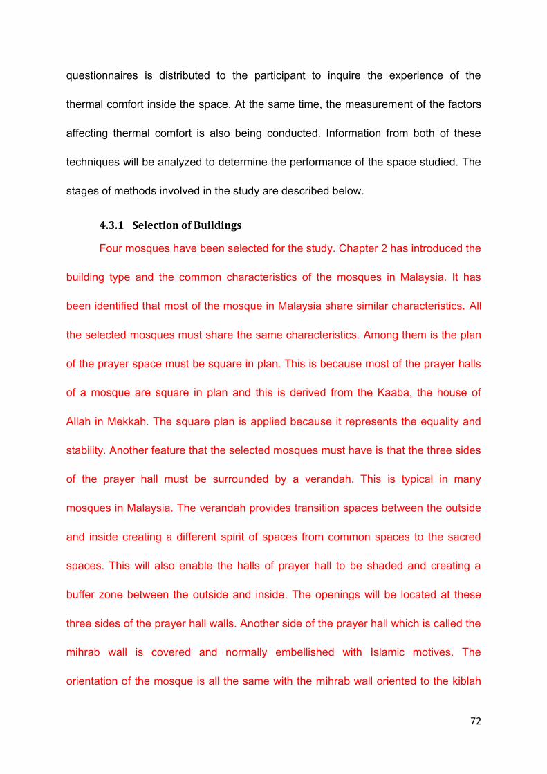
72
questionnaires is distributed to the participant to inquire the experience of the
thermal comfort inside the space. At the same time, the measurement of the factors
affecting thermal comfort is also being conducted. Information from both of these
techniques will be analyzed to determine the performance of the space studied. The
stages of methods involved in the study are described below.
4.3.1 Selection of Buildings
Four mosques have been selected for the study. Chapter 2 has introduced the
building type and the common characteristics of the mosques in Malaysia. It has
been identified that most of the mosque in Malaysia share similar characteristics. All
the selected mosques must share the same characteristics. Among them is the plan
of the prayer space must be square in plan. This is because most of the prayer halls
of a mosque are square in plan and this is derived from the Kaaba, the house of
Allah in Mekkah. The square plan is applied because it represents the equality and
stability. Another feature that the selected mosques must have is that the three sides
of the prayer hall must be surrounded by a verandah. This is typical in many
mosques in Malaysia. The verandah provides transition spaces between the outside
and inside creating a different spirit of spaces from common spaces to the sacred
spaces. This will also enable the halls of prayer hall to be shaded and creating a
buffer zone between the outside and inside. The openings will be located at these
three sides of the prayer hall walls. Another side of the prayer hall which is called the
mihrab wall is covered and normally embellished with Islamic motives. The
orientation of the mosque is all the same with the mihrab wall oriented to the kiblah

73
which is 292.7 degree from the north. There are two typical designs of mosques in
Malaysia that can be categorized into two main groups which are based on the roof
designs. They are the pitched and domed roof designs. Figure 4.2 and 4.3 illustrate
the typical designs of the pitched and domed roof mosque in Malaysia.
In selecting the mosques to be sampled, besides the characteristics
discussed before, the mosque must be naturally ventilated. The successful of the
design in responding to the climatic influences is one of the objectives that are
studied. Mosques that use the air conditioning system are not selected since the
mechanical system can control the thermal condition and comfort level inside a
space. The design of the building may not consider the climatic influences since the
indoor condition can be corrected by the mechanical system. It is important to study
how the typical design of a mosque responding to the climatic factors without much
help of the mechanical system. Therefore the study only focuses on the naturally
ventilated buildings.
As the one of the concerns of the study is to investigate the performance of
the two roof designs namely the pitched and domed roof, two samples for each type
of the roof designs are selected. There are many variations of the pitched and
domed roof design applied. For the study, the pitched roof design selected is the
three-tiered-roof design and the domed roof style selected is the half hemispherical
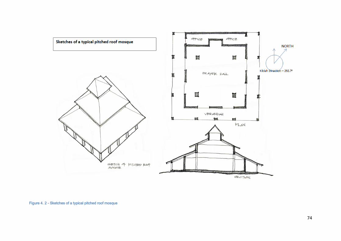
74
Figure 4. 2 - Sketches of a typical pitched roof mosque
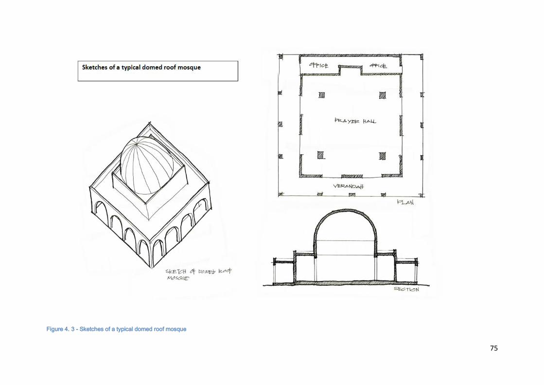
75
Figure 4. 3 - Sketches of a typical domed roof mosque

76
dome as shown in Figure 4.2 and 4.3 respectively. The three tiered pitched roof
design is selected because it is among the original traditional roof design being
applied in the mosque in Malaysia and commonly used due to its capability to cover
wider spaces. Similarly, the half hemispherical dome is the simplest and commonly
used in mosque designs. Another variation for the selection is the sizes of the
mosques. The mosques selected vary in sizes ranging from approximately 6500 m2
to 100 m2 . Such variation is to determine whether sizes affect the function of roof
design in affecting thermal condition inside the prayer hall.
Based on the criteria, four mosques have been selected. They share a lot of
similarities but mainly differ in the application of the roof design as discussed earlier.
The mosques that have been selected are:
a. Al Azim Mosque, Melaka. (2.20 North, 102.3 East)
Figure 4. 4 - The aerial view of the mosque (Google map)
NORTH
Kiblah Direction – 292.7o
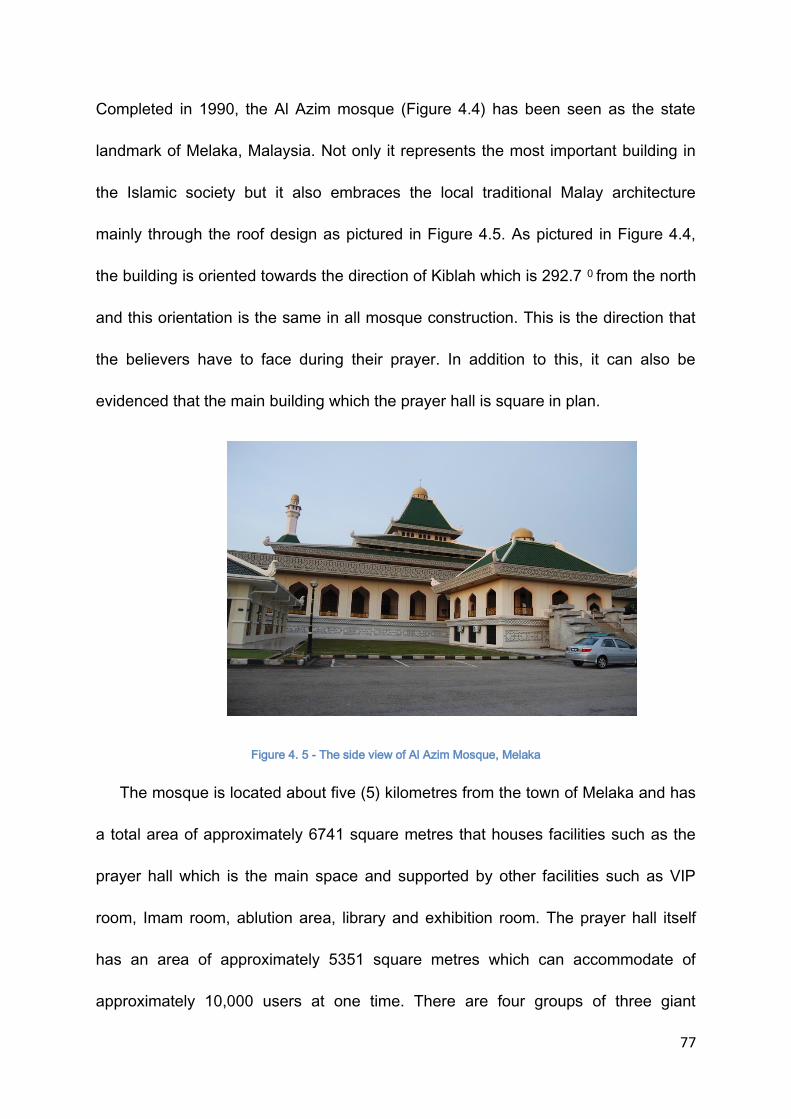
77
Completed in 1990, the Al Azim mosque (Figure 4.4) has been seen as the state
landmark of Melaka, Malaysia. Not only it represents the most important building in
the Islamic society but it also embraces the local traditional Malay architecture
mainly through the roof design as pictured in Figure 4.5. As pictured in Figure 4.4,
the building is oriented towards the direction of Kiblah which is 292.7 0 from the north
and this orientation is the same in all mosque construction. This is the direction that
the believers have to face during their prayer. In addition to this, it can also be
evidenced that the main building which the prayer hall is square in plan.
Figure 4. 5 - The side view of Al Azim Mosque, Melaka
The mosque is located about five (5) kilometres from the town of Melaka and has
a total area of approximately 6741 square metres that houses facilities such as the
prayer hall which is the main space and supported by other facilities such as VIP
room, Imam room, ablution area, library and exhibition room. The prayer hall itself
has an area of approximately 5351 square metres which can accommodate of
approximately 10,000 users at one time. There are four groups of three giant

78
columns located at the four corners of the prayer hall as displayed in Figure 4.6 to
support the huge roof structure, otherwise the space is an open plan and column
free space. The roof is a 3-tiered roof as displayed in Figure 4.5 which is embellished
Figure 4. 6 – The views of the prayer hall in Al Azim Mosque, Melaka
Figure 4. 7- The view of the verandah at Al Azim Mosque, Melaka
by a small dome at the highest point of the roof. A six-meter passageway (Figure
4.7) is provided around the prayer hall for easy access into the hall as well as to
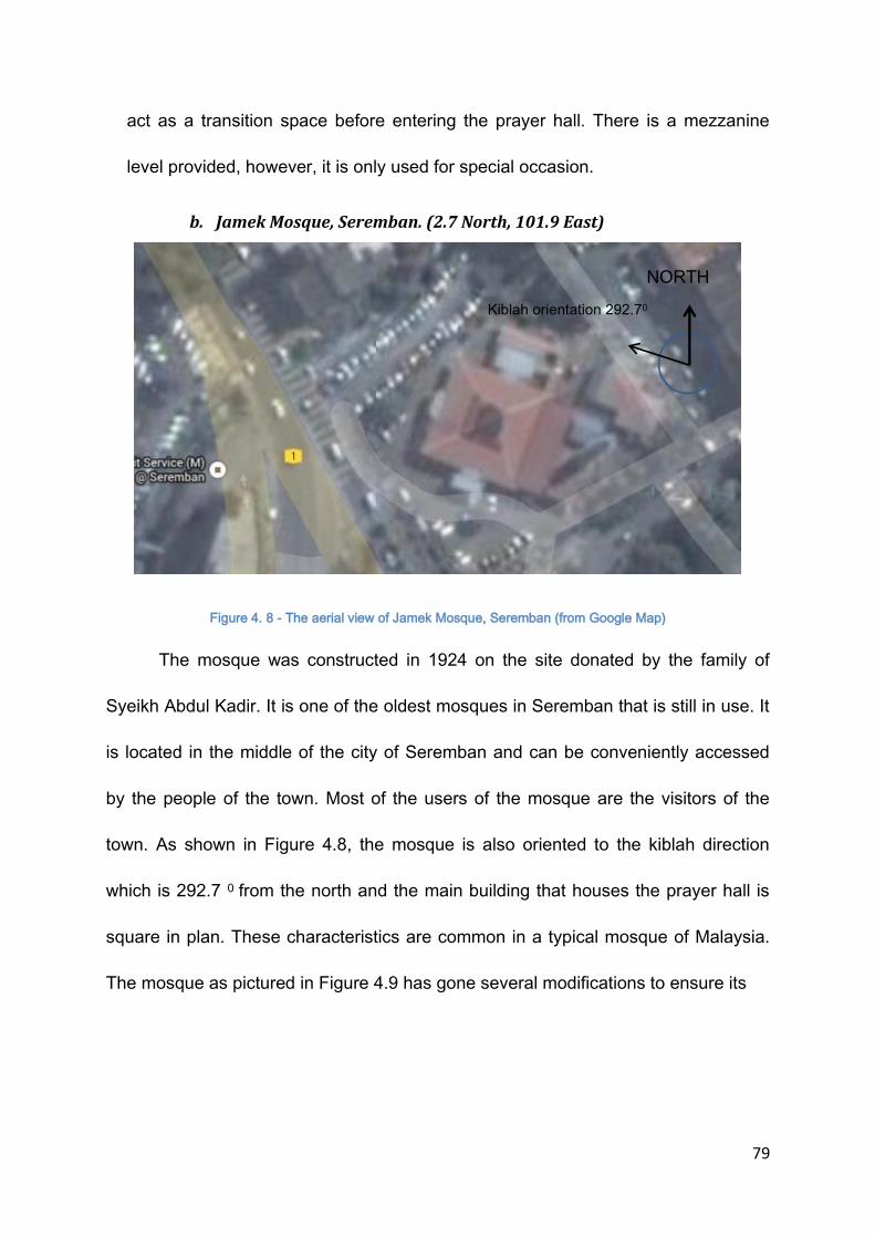
79
act as a transition space before entering the prayer hall. There is a mezzanine
level provided, however, it is only used for special occasion.
b. Jamek Mosque, Seremban. (2.7 North, 101.9 East)
Figure 4. 8 - The aerial view of Jamek Mosque, Seremban (from Google Map)
The mosque was constructed in 1924 on the site donated by the family of
Syeikh Abdul Kadir. It is one of the oldest mosques in Seremban that is still in use. It
is located in the middle of the city of Seremban and can be conveniently accessed
by the people of the town. Most of the users of the mosque are the visitors of the
town. As shown in Figure 4.8, the mosque is also oriented to the kiblah direction
which is 292.7 0 from the north and the main building that houses the prayer hall is
square in plan. These characteristics are common in a typical mosque of Malaysia.
The mosque as pictured in Figure 4.9 has gone several modifications to ensure its
NORTH
Kiblah orientation 292.70

80
Figure 4. 9 - Jamek Mosque, Seremban, Negeri Sembilan, Malaysia
structure stability and its occupancy capability. Extension such as creating vast area
of verandah around the main prayer hall has been made to allow the increasing
number of the users especially during the Friday noon prayer. This area can be used
as a relaxing or socializing area as this type of activity is prohibited inside the prayer
hall. Traditional method of construction using pitched roof is implemented in the
original main prayer hall of the mosque. Currently it can occupy up to 1000 people.
Figure 4. 10- The view of the prayer hall in Jamek Mosque, Seremban, Negeri Sembilan

81
The typical space arrangement of the Malaysian mosques is also evidenced
in this building as shown in Figure 4.10. The main space which is square in shape is
located at the centre of the building and surrounded by verandah (Figure 4.11) at the
three sides of the prayer hall. The side without the verandah is where the mihrab wall
is situated.
Figure 4. 11 – The view of the verandah at Jamek Mosque, Seremban, Negeri Sembilan
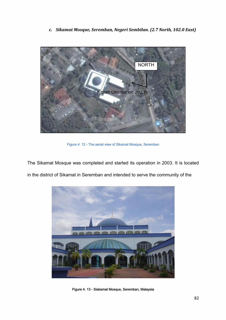
82
c. Sikamat Mosque, Seremban, Negeri Sembilan. (2.7 North, 102.0 East)
Figure 4. 12 - The aerial view of Sikamat Mosque, Seremban
The Sikamat Mosque was completed and started its operation in 2003. It is located
in the district of Sikamat in Seremban and intended to serve the community of the
Figure 4. 13 - Siakamat Mosque, Seremban, Malaysia
NORTH
Kiblah Orientation 292.70
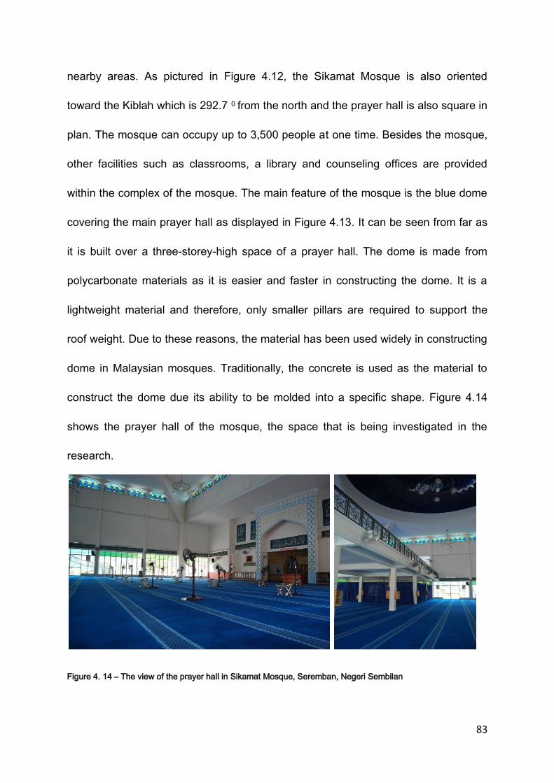
83
nearby areas. As pictured in Figure 4.12, the Sikamat Mosque is also oriented
toward the Kiblah which is 292.7 0 from the north and the prayer hall is also square in
plan. The mosque can occupy up to 3,500 people at one time. Besides the mosque,
other facilities such as classrooms, a library and counseling offices are provided
within the complex of the mosque. The main feature of the mosque is the blue dome
covering the main prayer hall as displayed in Figure 4.13. It can be seen from far as
it is built over a three-storey-high space of a prayer hall. The dome is made from
polycarbonate materials as it is easier and faster in constructing the dome. It is a
lightweight material and therefore, only smaller pillars are required to support the
roof weight. Due to these reasons, the material has been used widely in constructing
dome in Malaysian mosques. Traditionally, the concrete is used as the material to
construct the dome due its ability to be molded into a specific shape. Figure 4.14
shows the prayer hall of the mosque, the space that is being investigated in the
research.
Figure 4. 14 – The view of the prayer hall in Sikamat Mosque, Seremban, Negeri Sembilan

84
d. Al Mizan Mosque, Putrajaya. (2.9 North, 101.7 East)
Figure 4. 15 - The aerial view of the Al Mizan Mosque, Putrajaya (Goole map)
Al Mizan mosque (Figure 4.15) is the smallest mosque among the selected
mosques. It is located in Precinct 8, Putrajaya, Malaysia. It is intended to serve a
smaller local community. It has an area of approximately 324 meter square and
can occupy up to 250 people at a time. It has a concrete dome that covers the
central part of the prayer hall. Other part of the roof is a flat concrete roof.
Located in a small and confined site, the mosque is designed to be an open
facade mosque as an attempt to make the space feel spacious by making the
outdoor as part of the indoor environment. Vegetation of different heights and
density around the perimeter of the site is used to create shades to the prayer
hall which is normally shaded by the outer wall of the mosque. Verandah is
provided on the three side of the prayer hall, however, the verandah is directly
connected to the outdoor garden.
NORTH
Kiblah Orientation 292.70
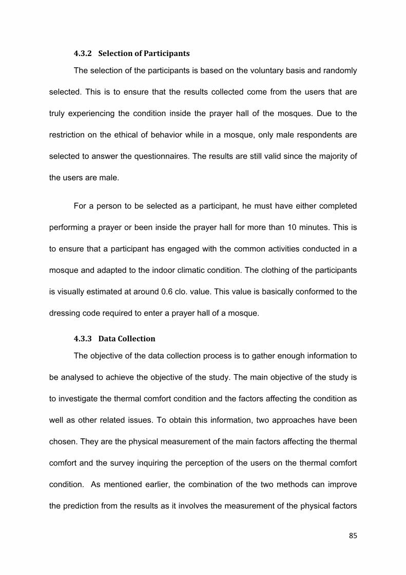
85
4.3.2 Selection of Participants
The selection of the participants is based on the voluntary basis and randomly
selected. This is to ensure that the results collected come from the users that are
truly experiencing the condition inside the prayer hall of the mosques. Due to the
restriction on the ethical of behavior while in a mosque, only male respondents are
selected to answer the questionnaires. The results are still valid since the majority of
the users are male.
For a person to be selected as a participant, he must have either completed
performing a prayer or been inside the prayer hall for more than 10 minutes. This is
to ensure that a participant has engaged with the common activities conducted in a
mosque and adapted to the indoor climatic condition. The clothing of the participants
is visually estimated at around 0.6 clo. value. This value is basically conformed to the
dressing code required to enter a prayer hall of a mosque.
4.3.3 Data Collection
The objective of the data collection process is to gather enough information to
be analysed to achieve the objective of the study. The main objective of the study is
to investigate the thermal comfort condition and the factors affecting the condition as
well as other related issues. To obtain this information, two approaches have been
chosen. They are the physical measurement of the main factors affecting the thermal
comfort and the survey inquiring the perception of the users on the thermal comfort
condition. As mentioned earlier, the combination of the two methods can improve
the prediction from the results as it involves the measurement of the physical factors

86
but also the information of the actual users (Bordass, 2003; Leaman and Bordass,
2007).
Prior to the actual data collection, a set of questionnaire (refer to Appendix A)
has been produced and a pilot study has been conducted to inquire the suitability
and applicability of the questions and the methods. Adjustments and improvements
have been made to the questionnaires to ensure that the questionnaires are clear
and they cover the necessary information required for the study. Before proceeding
to the data collection process, permission to sample the buildings is obtained from
the authority. It is important to ensure that the activities conducted do not interfere
with the activities and users inside the buildings. The data collection method is also
modified to minimize any interruption to the activities and the users inside the
mosques. The processes involved in the data collection through the use of survey
and physical measurement are described below.
a. Physical Measurement
The first process in data collection is to record the changes of the thermal
condition inside the prayer hall of the mosques. The common practice is to measure
the common factors affecting the thermal comfort which are air temperature, mean
radiant temperature, relative humidity, air movement, clothing value and metabolism.
In this research, the field measurement conducted is focused on the two more
important factors for this country or region which are the air temperature and relative
humidity. This information is instrumentally recorded using the ‘Tinytag’ data loggers
(Figure 4.16). There are factors that are not instrumentally recorded in the research
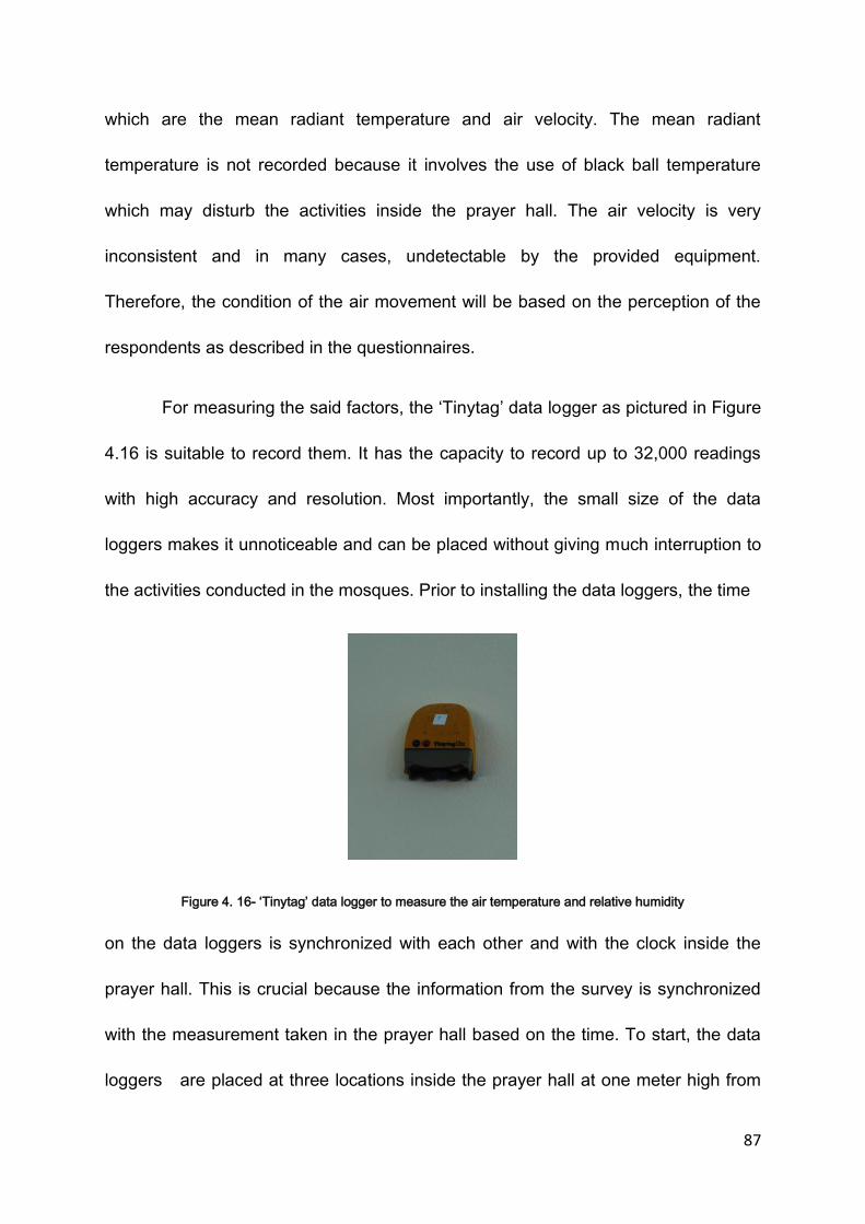
87
which are the mean radiant temperature and air velocity. The mean radiant
temperature is not recorded because it involves the use of black ball temperature
which may disturb the activities inside the prayer hall. The air velocity is very
inconsistent and in many cases, undetectable by the provided equipment.
Therefore, the condition of the air movement will be based on the perception of the
respondents as described in the questionnaires.
For measuring the said factors, the ‘Tinytag’ data logger as pictured in Figure
4.16 is suitable to record them. It has the capacity to record up to 32,000 readings
with high accuracy and resolution. Most importantly, the small size of the data
loggers makes it unnoticeable and can be placed without giving much interruption to
the activities conducted in the mosques. Prior to installing the data loggers, the time
Figure 4. 16- ‘Tinytag’ data logger to measure the air temperature and relative humidity
on the data loggers is synchronized with each other and with the clock inside the
prayer hall. This is crucial because the information from the survey is synchronized
with the measurement taken in the prayer hall based on the time. To start, the data
loggers are placed at three locations inside the prayer hall at one meter high from
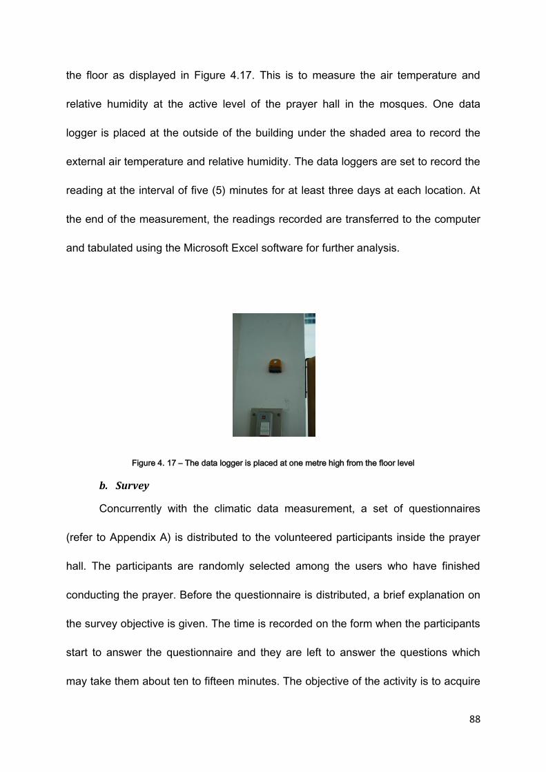
88
the floor as displayed in Figure 4.17. This is to measure the air temperature and
relative humidity at the active level of the prayer hall in the mosques. One data
logger is placed at the outside of the building under the shaded area to record the
external air temperature and relative humidity. The data loggers are set to record the
reading at the interval of five (5) minutes for at least three days at each location. At
the end of the measurement, the readings recorded are transferred to the computer
and tabulated using the Microsoft Excel software for further analysis.
Figure 4. 17 – The data logger is placed at one metre high from the floor level
b. Survey
Concurrently with the climatic data measurement, a set of questionnaires
(refer to Appendix A) is distributed to the volunteered participants inside the prayer
hall. The participants are randomly selected among the users who have finished
conducting the prayer. Before the questionnaire is distributed, a brief explanation on
the survey objective is given. The time is recorded on the form when the participants
start to answer the questionnaire and they are left to answer the questions which
may take them about ten to fifteen minutes. The objective of the activity is to acquire
89
the perception of the users of the selected mosques on the thermal comfort condition
in the prayer halls and their preferences according to the condition experienced.
To achieve this, the set of questionnaires has been carefully produced to
allow the participants to evaluate and select the thermal sensation they experienced
while in the mosque by marking the thermal sensation level based on ASHRAE 7-
point scale and the Bedford scale as shown in Table 4.1. The ASHRAE 7-point scale
is used to inquire about the thermal sensation and the Bedford scale is used to
indicate the level of thermal comfort that the respondents have experienced while in
the space.
ASHRAE Scale Bedford
Too Hot 3 7 Much Too Warm
Hot 2 6 Too Warm
Warm 1 5 Comfortably warm
Normal 0 4 Comfortable
Cool -1 3 Comfortably cool
Cold -2 2 Too Cool
Too Cold -3 1 Much Too Cool
Table 4. 1 - The ASHRAE 7 thermal sensation scale and Bedford scale
Along with these questions, the participants are also asked about the
sensation they experienced regarding the level of air movement, humidity level and
their preferences to the existing condition. The air movement inside the mosque is
rarely consistent at all time unless mechanical equipment is used. Therefore an
assumption is made to the speed of air felt or experienced by the users at the point
of time they answer the question. For the purpose of this study, the wind condition is

90
divided into four categories which are calm (< 0. 5 m/s), breezy (between 0.5 m/s
and 1.5 m/s), windy (between 1.5 -2.0m/s) and very windy (more than 2.0 m/s). The
humidity level they experienced is measured by the level of sweating. It is difficult to
sense the level of humidity with our bare skin. The only easy explanation to measure
the existence of humidity in the air is through the level of sweat accumulation on the
skin which is closely associated with the content of humidity in the air. Due to the fact
that the air temperature for the country’s climate is almost high and people tend to
sweat at all time, the method selected for measuring the perception of the humidity
level is thought to be appropriate. Four scales are given which are dry, normal,
sweating (humid) and heavy sweating (very humid). In addition, the participants are
also asked to choose the condition they would like to be if they are given the chance
to change to the existing environment. They are provided with three options to
change which are to reduce, unchanged or increase to the three physical
environmental conditions which include air temperature, humidity level and air
movement condition. At the end of the survey, the time and date are checked to
acquire the readings of the air temperature and the relative humidity from the
recorded readings from the data loggers. The information is tabulated using the
Microsoft Excel 2007 for further analysis.
The survey is only conducted during the specific time which is after each
congregational prayer. These are the periods of time during the day that the
mosques will have better occupancy compared to any other periods of time. The
mosques however, are open from as early as 5.00 am in the morning until 10.00 pm
91
in the evening, and can be accessed during this period however the occupancy level
is better during the congregational prayers. Depending on the size of the mosque,
5% to 20% capacity can be achieved during daily congregational prayer. A full
capacity can only be achieved during weekly congregational prayer which is on
Friday. There are five congregational prayers conducted each day which are:
i. Dawn prayer (subh) – 6.00 am – 7.30 am
ii. Noon prayer (Zuhr) – 1.00 pm – 4.30 pm
iii. Afternoon prayer ( Asr) – 4.30 pm – 7.00
iv. Dusk prayer (Maghrib) - 7.30pm – 8.30pm
v. Evening prayer ( Isya) – 8.30 – until Dawn prayer
The Friday congregational prayer is not included in the survey due to the disturbance
that may occur during the survey which is inappropriate to the religion.
4.3.4 Data Analysis
The analysis of the collected data is intended to provide information regarding
the thermal comfort condition inside the prayer hall of the selected mosque. For the
purpose of the analysis, instead of using the five periods of time of the
congregational prayers, three periods of time which are the noon (from 1.00 pm until
2.30 pm), afternoon (from 3.30 pm until 5.00 pm) and evening (from 7.00 until 9.30
pm) are introduced. These are the duration of time that the mosques are mostly
occupied and the condition of the climate during the three periods of times is
relatively similar. The Subh prayer time which is early in the morning is not included

92
in the research since the condition during this time is mostly comfortable. There are
many objectives planned to be achieved with the analysis. The objectives are:
a. To inquire the users’ perception on the thermal comfort condition of the
two typical types of mosques designs in Malaysia which are the pitched
and domed roof mosques.
The data concerning the thermal comfort sensation are gathered for each of
the mosque (refer to Appendix B). The votes counted for this purpose are based on
the Bedford scale which is based on the seven scales ranging from ‘much too cool’
to ‘much too warm’. The Bedford scale is selected rather than the ASHRAE 7
thermal sensation scale because the Bedford scale is more relevant in describing the
thermal comfort with the addition of word ‘comfortable’ in the scale compared to the
ASHRAE scale which is more related to the thermal sensation rather than thermal
comfort perception. Based on the votes received, the results are tabulated and
converted to a bar chart. The charts from each type of the mosques are compared to
find the perception of the users on the more thermally comfortable mosque.
b. To inquire the dominating factor and other contributing factors of
thermal comfort inside the prayer halls of the mosques
Included in the set of questionnaires is the inquiry about the sensation of the
factors affecting the thermal comfort that the participants have experienced. The
factors include thermal sensation, humidity level and air movement condition. The
votes received are collected and tabulated using the bar chart. Cross tabulation
between the votes on the thermal comfort sensation and the votes of the sensation
on the other factors described earlier can suggest how thermal comfort can be

93
affected by each factor. It can also suggest which factors are influential in influencing
the thermal comfort sensation. The votes on the preferences are also investigated to
confirm the desired conditions affecting the thermal comfort level.
c. To predict the range of tolerable indoor air temperature for the prayer
halls of the selected mosques.
It has been agreed by the researchers that the tolerable range of air
temperature is between -1 (cool) and +1 (warm) based on the ASHRAE thermal
sensation 7-scale and between 3(comfortably cool) and 5 (comfortably warm) under
the Bedford Scale. For determining the tolerable air temperature, the ASHRAE scale
and the Bedford scale are applied. With the recorded air temperature and relative
humidity, the votes under the two scales of thermal sensation are counted and
tabulated. They are averaged and compared. A graph showing the linear regression
based on the relationships between the air temperature and the votes based on the
two scales is applied to predict the maximum range of tolerable air temperature
(when the vote is equal to 1).
d. The appropriate methods of evaluating the thermal comfort condition for
this climate and region and specifically for this building type.
ASHRAE 7 thermal sensation scale and Bedford scale are the two frequently
used subjective measurement tools in evaluating thermal comfort condition
throughout the world. They have been accepted in many countries especially in
countries with moderate climate and they are proven to produce acceptable results.
The study also looks at the two scales and their applicability for this region and
climate. Cross checking analysis between these two indexes is done to come out
94
with a proper and acceptable range of air temperature. The methods adapted in
producing the acceptable range is later on suggested to be used in evaluating the
thermal comfort condition for the hot and humid countries, specifically, Malaysia.
4.4 COMPUTER MODELING
The availability of computer modeling has helped to investigate the
performance of a building without having to build the real building (Li and others,
2007). In this research, an investigation using computer modeling is appropriate as
it can minimize the variations created by the real buildings and environment. The
objective of using the modeling tool is to investigate and compare the performance of
the mosque with the two types of roof based on the generated indoor thermal
condition inside the prayer hall of the mosques. The pitched and domed roofs are
two most common roof designs applied in Malaysian mosques. The computer
modeling is used to simulate the indoor heat gain from the influences of the external
conditions and compare the performance between the mosque with the pitched roof
and the domed roof.
For this purpose, a software called HTB2 (Alexander, 1996) and WinAir4 are
chosen in assisting the investigation. HTB2 is an improved investigation tool of the
previous Heat Thermal Balance (HTB) software developed at Welsh School of
Architecture, Cardiff (Alexander and Jones, 1996). It is simple but able to simulate
the indoor thermal condition based on the various variables such as thermal outdoor
conditions including air temperatures and humidity, the materials of the building for

95
each building elements and energy usage as well as the usage patterns by the users
(Alexander and Jones, 1996). In comparison with other investigative tools available
in the market, HTB2 is chosen for this investigation because it can provide detailed
data on short-time scale such as minutes and weeks and this is suitable for this
investigation as the investigation will look for the changes happened throughout the
day. In addition to this, HTB2 does not require the actual drawing of the building
investigated. It only requires the representation of the building as it focuses more on
the operation of the occupied buildings. A building is defined as a set of spaces
linked together and to the outside with building elements and affected by a set of
influences originating from external climatic factors, heating system and other
operational system (Alexander and Jones, 1996). Based on these influences, a new
result will be generated in the investigated space. As the research is focused on the
operation of the building and focusing on one of the building elements which is the
roof, the use of HTB2 is appropriate for the investigation. Figure 4.18 shows the
fundamental of the processes and interactions of the climatic factors and building
elements in HTB2.

96
Figure 4. 18 - Fundamental Building Processes and Interactions (Alexander, 1996)
WinAir4 software is also used to show the distribution of air according to the
temperature inside the space investigated. The geometry of the building investigated
together with the influences acted on the building must be loaded to the system for
the system to work. In HTB2, only data will be provided however in WinAir4 the
distribution of the temperature around the space can be seen. This will improve the
analysis of the thermal condition of the building. Figure 4.19 shows the examples of
the output from the simulation conducted using WInAir4.

97
Figure 4. 19 - The output of data plot using WinAir4 showing the air flow and distribution according the
temperature inside a space
With the combination of WinAir4 software, the distribution of air temperature inside
the space investigated can be visualized.
Before using the thermal simulation tool, a confident study is conducted to
inquire the capability of the tool to simulate the situation studied for the building type.
In this study, the recorded outdoor temperature from the site is utilized and the
results of the space air temperature of the prayer hall from the simulation tool are
compared with the recorded temperature form the building samples. It shows that the
patterns of the air temperature generated from the tool are very similar to the pattern
from the measured reading. Having this validated, the following study is to

98
investigate the performance of two typical designs of Malaysian mosques. To
conduct the investigation, the two typical models of Malaysian mosques, a pitched
roof mosque and a domed roof mosque, are constructed for the simulation process.
Both of them share the same qualities but differ in the roof construction which also
affects the volume of the space. The construction types and materials used are the
same for both of the buildings except the roof. This information is used in
constructing the model in the HTB2 and WinAir4 software with the input of the
outdoor climate conditions obtained from the Malaysian Meteorological office.
4.4.1 The Mosque Model – Dome and Pitch
Two models, a domed mosque and pitched mosque are constructed for the
purpose of the simulation. The design of Malaysian mosques is relatively similar to
each other especially in the space organization. The differences are more
distinguished on the appearances of the building which are heavily influenced by the
building envelope especially the roof. The two models selected are the most popular
designs employed in the Malaysian mosques. The pitched roof is more traditional,
whereas the domed roof is claimed to be more Islamic. Figure 4.2 and figure 4.3
show the typical plan and section of the pitched roof mosque and the domed roof
mosque respectively.
4.4.2 Data Collection
The data collected for the simulation process are divided into two
categories which are the input data, gathered from specification of the

99
buildings modeled, and the output data, generated from the simulation
process.
a. The Input
The input data is required to build the model of the building in the
simulation tool. The information includes:
i. Building Information
Information that is specified under the building includes the
geographical location of the building in terms of its latitude and
longitude position. It also includes the details of the building
investigated which consist of the materials and their properties, the
spaces or zones of the building to be investigated, the building
elements, constructions and layout of the elements.
For the purpose of the study, the location selected for the building
is Kuala Lumpur(101.7 o, 2.9o). Kuala Lumpur is the capital city of
Malaysia. The city has a complete and sufficient climatic data that
is needed as an input for the HTB2.
For the modeled building, the spaces in the mosque are divided
into five divisions as shown in the Table 4.2 to represent the
spaces making up the whole mosque. However, the study is only
focused to the main space which is the prayer hall. The elements of
the building such as the walls, floors, roofs and windows are as
specified in the Table 4.3.

100
Space code Space name Area (m2) Volume (m3)
1 Prayer hall 900 9951
2 East Verandah 196 1176
3 West verandah 196 1176
4 South Verandah 216 1296
5 Office 180 1080
Table 4. 2 - Space divisions for the modelled mosque
Construction Description Material Width (m)
1 External wall Plaster, brick, plaster
0.016, 0.105, 0.016
2 Single glazing Window glass 0.006
3 Solid ground floor Carpet, concrete, earth
0.015, 0.100, 1.60
4 Internal ceiling Insulation quilt, plasterboard
0.10, 0.01
5 Roof Tiles 0.01
6 Internal partition Plaster, brick(inner), plaster
0.016, 0.105, 0.016
7 Timber grille wall/partition
Timber (oak) 0.19
8 Concrete roofing Concrete (light mix)
0.450
9 Roof 1 Roof tiles, Styrofoam, plasterboard
0.013, 0.085.0.013
10 Solid ground floor with tiles
Tiles, concrete, earth
0.30, 0.1, 1.6
11 Opening Void 0.015
12 Dome roofing Polycarbonate 0.012
Table 4. 3 - Description of building elements for the modelled mosque
ii. Operative Information
Operative information includes the data for the meteorological
condition which is provided by the local Meteorological Department
for the area of Kuala Lumpur. The simulation is set to take place for

101
ten days allowing to building to the heating up process for two
days.
iii. Services
The information included in this category is the heating and cooling
system, lighting circuits, small power sources, occupants and
ventilation characteristics. For the purpose of the study, all the
information about services is ignored except the ventilation
characteristics. The building is naturally ventilated and no heating
and cooling system involved. The involvement of major equipment
that contributes to the heat gain is also minimal and the usage of
lighting is kept to the minimal as well. As the focus of the research
is more to the performance of the building in relation to its
construction design, the building elements are given more
emphasized in the study.
b. The Output
The output data is the information obtained after the simulation process
has been conducted. The software is able to predict the indoor air
temperature, relative humidity and mean radiant temperature of the
spaces made earlier based on the input data. In addition to this, it can also
predict the surface temperature and the energy transferred from surfaces.
These are among the output that can be generated through the use of the
software.
102
4.4.3 Data Analysis
Using the data from the Meteorological Office of Malaysia for the
outdoor climate condition and the data obtained from specification of the
constructed models of a typical pitched roof and domed roof mosques, HTB2
and WinAir4 are employed to produce the predicted indoor thermal condition
of the buildings. The results obtained from the simulation are analyzed using
the comparative method between the results of two constructed model
mosques. The aim of the analysis is to investigate the effects of the indoor
thermal condition when the two different types of roof being applied to the
same space. The study is focused on the aspects that are listed below. They
are:
a. The heat gain and loss pattern
The study is to inquire the heat gain pattern for the two types of the
mosques. Using the same building but replacing it with the domed roof
and pitched roof, the heat gain and loss pattern can be generated
using the HTB2 software. Comparison between the patterns can be
made to evaluate the performance of the roof in filtering the outdoor
thermal condition into the indoor space.
b. The influence of the opening area and the heat gain
The total area of the openings provided controls the amount of air
changes between the inside and outside. This affects the air
temperature of the interior and natural ventilation for the purpose of
103
providing thermally comfortable environment. A variation in the size of
the openings is tested to investigate the effect on the air temperature.
c. The roof space vs. the prayer hall space
Due to the difference in the roof design, the roof space provided is
investigated to inquire if it affects the air temperature of the inside
space.
d. Wind movement pattern and air temperature distribution
The influence of the roof design to the pattern of the wind movement is
investigated. The geometry of the roof design is different from each
other. Therefore it is possible that the air movement pattern is
influenced by the roof geometry since other design characteristics are
the same.
4.5 CONCLUSION
Determining the thermal comfort level of a space involves the psychological
factors as well as physical factors. Many psychological factors deal with the feeling
and personality whereas the physical factors are more towards the measured value.
Combining the methods of survey and field measurement in data acquisition is
relevant because in the survey, the questionnaire is designed to inquire about the
feeling and the perception of the participants. On the other hand, the field
measurement records the value of the physical factors affecting the thermal comfort.
Combining the results from the two data acquisition produces results that consider
not only the physical aspects but also the psychological factors. In addition, the

104
availability of the computer simulation tools enables the investigation on the
influence of the building design on the thermal comfort to be conducted without
having to interfere with the activities of the building. Combining the three approaches
produces thorough investigation regarding the issue of thermal comfort for the typical
Malaysian mosques.

105
CHAPTER 5 – RESULTS AND DISCUSSION
( Survey and Field Measurement)
5.1 INTRODUCTION
This chapter exhibits and discusses the results obtained from the information
gathered through the field measurement and survey. Previously, Chapter 4
describes the methodology applied in collecting, obtaining and analysing information
regarding the research. Chapter 5 starts with the introduction to the investigation
conducted. It follows with the results and discussion of the pilot study conducted
earlier on the small scale mosques located in Putrajaya. Then, the chapter continues
with the results and discussion on the case studies conducted. It is divided into four
sections with each section discusses results from each case study. The result
presented in each case study is about the thermal comfort level of prayer halls
experienced by the participants involved in the research. It also includes the
discussion on the evaluative method and factors affecting thermal comfort level of
the space. Based on the information, the section continues with the discussion of
the predicted range of acceptable space air temperature for the space. Finally, the
chapter summarizes the discussion on the case studies.
5.2 GENERAL BACKGROUND
One of the main reasons to the decreasing numbers of people attending the
congregation prayers conducted five times a day is due to the thermally
uncomfortable environment inside the prayer hall of many mosques in Malaysia.
Even though the buildings play a significant role in the Muslim society which

106
comprises the majority of the Malaysia’s population, the buildings fail to function
effectively due to this condition. Thus, the issue of thermal comfort condition inside a
prayer hall in a mosque has recently become crucially important to ensure that the
mosques are functionally well and able to play its important role in making a better
society. Recently, many existing mosques designed to be naturally ventilated have
been converted to air conditioned mosque in an attempt to tackle the thermally
uncomfortable condition inside the prayer hall. This action indicates that the design
has failed to provide a thermally comfortable indoor environment. It is rather costly
economically and environmentally which contributes to the accumulation of polluted
condition of the environment.
One of the reasons for this happening is due to the scarcity of available
information regarding the thermal comfort condition for the specific type of building.
The lack of understanding or knowledge on the ways of building elements
transferring or losing heat to and from the space may have caused the failure to
provide comfortable indoor environment. In addition to this, the reference to the
acceptable or tolerable indoor air temperature and other condition is either
unavailable or wrongly estimated. In order to tackle the problem, the knowledge
regarding the matters should be available to be referred and most importantly,
guidelines suggesting the tolerable comfort air temperature for the space in Malaysia
should be available and correctly interpreted. Currently, specific knowledge and
guidelines are lacking for this type of building in this type of climate.

107
In an attempt to provide the necessary knowledge, a study is conducted on
the thermal comfort perception of four selected typical mosques in Malaysia. It is
aimed to provide knowledge to be used as a guideline for the future naturally
ventilated mosque construction. Four mosques ranged from the state mosques to
the community mosques have been selected for the study. They are:
a. Al Azim Mosque, Melaka. – ( State mosque)
b. Jamek Mosque, Sereemban. ( Community mosque)
c. Sikamat Mosque, Seremban. (District Mosque)
d. Al Mizan Mosque, Putrajaya.(Local Community mosque)
At the earlier stage of the study, a pilot study was conducted on two small scale
mosques located in Putrajaya, Malaysia. They are:
a. Al Mizan Mosque, Putrajaya
b. Section 9 Mosque, Putrajaya
5.3 PILOT STUDY
Prior to the actual investigation and data collection process, a pilot study had
been conducted on two small scale mosques located in Putrajaya. The purpose of
the study is to inquire the suitability of the methodology and to test the understanding
of respondents on the questionnaire designed. The investigation was conducted
during a noon prayer time between 1.00 pm until 3.30 pm for one day on each
mosque. 20 participants had involved in the pilot study. A set of questionnaire asking
on the thermal sensation based on the ASHRAE 7 thermal sensation scale was
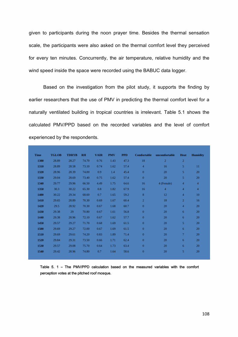
108
given to participants during the noon prayer time. Besides the thermal sensation
scale, the participants were also asked on the thermal comfort level they perceived
for every ten minutes. Concurrently, the air temperature, relative humidity and the
wind speed inside the space were recorded using the BABUC data logger.
Based on the investigation from the pilot study, it supports the finding by
earlier researchers that the use of PMV in predicting the thermal comfort level for a
naturally ventilated building in tropical countries is irrelevant. Table 5.1 shows the
calculated PMV/PPD based on the recorded variables and the level of comfort
experienced by the respondents.
Table 5. 1 – The PMV/PPD calculation based on the measured variables with the comfort
perception votes at the pitched roof mosque.
Time TGLOB TDRYB RH VAIR PMV PPD Comfortable uncomfortable Heat Humidity
1300 28.89 28.27 74.70 0.76 1.43 47.3 18 2 2
1310 28.89 28.58 73.10 0.74 1.62 57.4 4 16 5 11
1320 28.96 28.39 74.00 0.9 1.4 45.4 0 20 5 20
1330 29.04 28.69 73.40 0.75 1.62 57.4 0 20 5 20
1340 29.77 29.96 66.50 4.49 1.75 64.6 16 4 (Female) 4 4
1350 30.3 30.22 65.30 0.8 1.82 67.9 16 4 4 4
1400 30.22 29.34 68.60 0.7 1.65 59.2 8 12 4 10
1410 29.65 28.89 70.30 0.69 1.67 60.4 2 18 2 16
1420 29.5 28.92 70.30 0.67 1.68 60.7 0 20 4 20
1430 29.38 29 70.80 0.67 1.61 56.8 0 20 6 20
1440 29.38 28.96 72.10 0.67 1.62 57.7 0 20 6 20
1450 29.57 29.27 71.70 0.68 1.69 61.5 0 20 5 20
1500 29.69 29.27 72.00 0.67 1.69 61.5 0 20 6 20
1510 29.69 29.61 74.20 0.83 1.89 71.4 0 20 7 20
1520 29.84 29.31 73.50 0.66 1.71 62.4 0 20 6 20
1530 29.57 29.08 75.70 0.64 1.73 63.4 0 20 6 20
1540 29.42 28.96 74.80 0.7 1.64 58.6 0 20 5 20
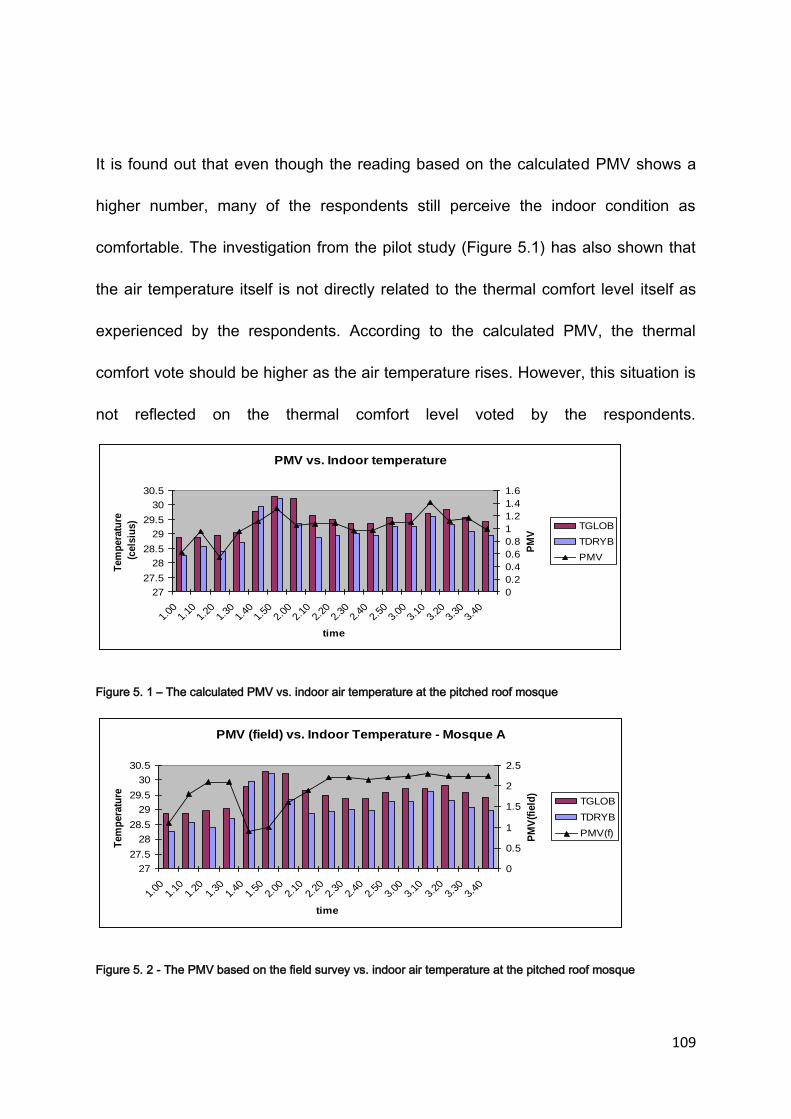
109
It is found out that even though the reading based on the calculated PMV shows a
higher number, many of the respondents still perceive the indoor condition as
comfortable. The investigation from the pilot study (Figure 5.1) has also shown that
the air temperature itself is not directly related to the thermal comfort level itself as
experienced by the respondents. According to the calculated PMV, the thermal
comfort vote should be higher as the air temperature rises. However, this situation is
not reflected on the thermal comfort level voted by the respondents.
Figure 5. 1 – The calculated PMV vs. indoor air temperature at the pitched roof mosque
Figure 5. 2 - The PMV based on the field survey vs. indoor air temperature at the pitched roof mosque
PMV vs. Indoor temperature
27
27.5
28
28.5
29
29.5
30
30.5
1.00
1.10
1.20
1.30
1.40
1.50
2.00
2.10
2.20
2.30
2.40
2.50
3.00
3.10
3.20
3.30
3.40
time
Tem
pera
ture
(cels
ius)
0
0.2
0.4
0.6
0.8
1
1.2
1.4
1.6
PM
VTGLOB
TDRYB
PMV
PMV (field) vs. Indoor Temperature - Mosque A
27
27.5
28
28.5
29
29.5
30
30.5
1.00
1.10
1.20
1.30
1.40
1.50
2.00
2.10
2.20
2.30
2.40
2.50
3.00
3.10
3.20
3.30
3.40
time
Tem
pera
ture
0
0.5
1
1.5
2
2.5
PM
V(f
ield
)
TGLOB
TDRYB
PMV(f)

110
Figure 5.2 shows the comparison between the PMV based on the calculation and the
field survey. Based on the calculated PMV, the rise on the air temperature is
followed by the rise in the PMV value. However, according to the respondents’
perception, the PMV can be lower even though the air temperature is higher. The
change in the thermal comfort level to a better condition can be evidenced when the
wind movement is present as shown in the next figure (Figure 5.3). It is also
Figure 5. 3 – The velocity of air vs the PMV based on the field survey
observed that only a strong wind can assist in providing thermally comfortable
environment. With the wind speed less than 2m/s, the thermal comfort level is
insignificantly affected. Further investigations need to be conducted on a larger scale
and modification on the questionnaire and methodology relevant to the study is
made as discussed in the previous chapter.
5.4 CASE STUDY 1 – AL AZIM MOSQUE, MELAKA, MALAYSIA
A study involving a field measurement and survey has been conducted at the
Al Azim Mosque, Melaka, Malaysia. It is a modern building but it implements a
traditional design that uses the traditional three tired pitched roof which is very
Air Velocity vs. PMV (field)
0
1
2
3
4
5
1.00
1.10
1.20
1.30
1.40
1.50
2.00
2.10
2.20
2.30
2.40
2.50
3.00
3.10
3.20
3.30
3.40
Time
Air
velo
cit
y
0
0.5
1
1.5
2
2.5
PM
V (
field
)
VAIR
PMV(f)

111
vernacular to Malaysia. A total of 119 respondents are involved in the thermal
comfort perception survey conducted for this mosque with the distribution of 41
people for the noon prayer, 24 respondents for the afternoon prayer and 54
participants for the evening prayer time.
5.4.1 Thermal Comfort Perception
Table 5.2 and Figure 5.4 show the number and percentage of votes received
during noon, afternoon and evening time based on the thermal comfort perception.
Table 5. 2 - The average, min and max for the air temperature and relative humidity according to the thermal
comfort vote and the periods of prayer time at Al Azim Mosque Melaka.
Based on the responses gathered from the survey, 51% of the respondents consider
that the noon time is ‘too warm’. The other 49% consider that the indoor condition is
thermally acceptable which is shown by the ‘comfortably warm’ (29%) and
‘comfortable’ (20%) votes. The percentage of votes for the ‘too warm’ condition
during the afternoon time increases to 63%. Only 37% of the respondents accept the
condition as thermally comfortable. During the evening time, the percentage of the
votes for ‘too warm’ which reflected the thermally uncomfortable condition is 61%

112
Note: Seven levels of Bedford scale are used for the thermal comfort level but only the three levels are shown because no vote is received for comfortably cool, too cool, much too cool and much too warm.
Figure 5. 4 - The percentage of thermal comfort votes based on the Bedford scale according to the prayer times
at Al Azim Mosque, Melaka
which is less than the votes received during the afternoon time but it is still high
compared to the votes received during the noon time. Based on the information, it
suggests that the less comfortable period occurs between the afternoon prayer time
(4.00 pm) until the evening prayer time (9.30 pm). The average temperature during
the noon time is 30.3 degree Celsius with 67.6% of relative humidity (RH). During the
afternoon time, the average temperature is 30.6 degree Celsius with 75% of relative
humidity and during the evening time, the average is 29.7 degree Celsius for the air
temperature with 77.4% of relative humidity (RH).
It is noted that the difference in the average air temperature is relatively small
(0.2 – 0.5 0 Celsius) between these periods of time. The small changes in the air
temperature are normally insignificant in changing the thermal comfort level. Unlikely
in this case, it can be evidenced that even though the changes in the average air
temperature are minimal, there is a quite substantial change in the percentage of
51 63 61
29 29 39
20 8
0 0
20
40
60
80
Noon Afternoon Evening
Per
cen
tage
(%
)
Prayer Time
Thermal Comfort Level at Al Azim
Too warm Comfortably warm Comfortable
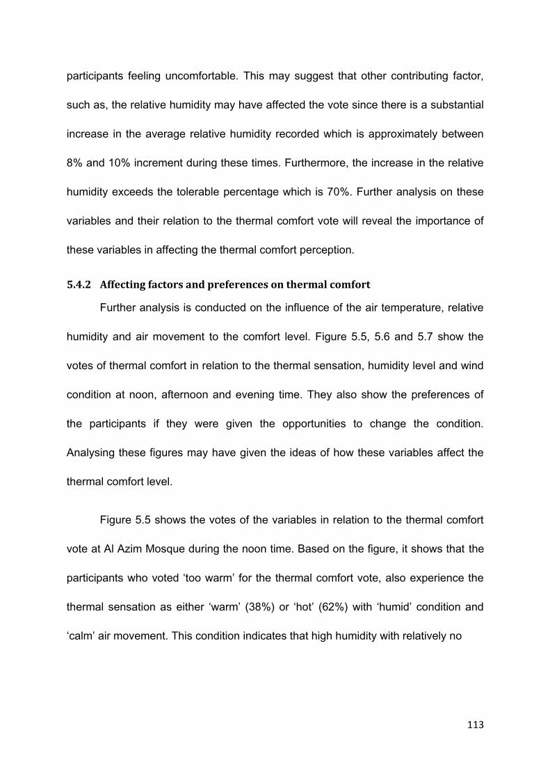
113
participants feeling uncomfortable. This may suggest that other contributing factor,
such as, the relative humidity may have affected the vote since there is a substantial
increase in the average relative humidity recorded which is approximately between
8% and 10% increment during these times. Furthermore, the increase in the relative
humidity exceeds the tolerable percentage which is 70%. Further analysis on these
variables and their relation to the thermal comfort vote will reveal the importance of
these variables in affecting the thermal comfort perception.
5.4.2 Affecting factors and preferences on thermal comfort
Further analysis is conducted on the influence of the air temperature, relative
humidity and air movement to the comfort level. Figure 5.5, 5.6 and 5.7 show the
votes of thermal comfort in relation to the thermal sensation, humidity level and wind
condition at noon, afternoon and evening time. They also show the preferences of
the participants if they were given the opportunities to change the condition.
Analysing these figures may have given the ideas of how these variables affect the
thermal comfort level.
Figure 5.5 shows the votes of the variables in relation to the thermal comfort
vote at Al Azim Mosque during the noon time. Based on the figure, it shows that the
participants who voted ‘too warm’ for the thermal comfort vote, also experience the
thermal sensation as either ‘warm’ (38%) or ‘hot’ (62%) with ‘humid’ condition and
‘calm’ air movement. This condition indicates that high humidity with relatively no

114
Note: Seven levels of Bedford scale are used for the thermal comfort level but only the three levels are shown because no vote is received for comfortably cool, too cool, much too cool and much too warm.
ASHRAE 7-point scale is used for the thermal sensation but only three points which are neutral, warm and hot are shown because other points do not receive any vote for the period of time investigated.
Figure 5. 5 - The percentage of votes on the thermal sensation, relative humidity, wind condition and preferences
vote in relation with the comfort vote based on the Bedford scale at Al Azim Mosque, Melaka during the noon
prayer time.
air movement can cause thermal discomfort with either ‘warm’ or ‘hot’ categories of
air temperature. In this figure, it is also pointed out that the participants feel
‘comfortably warm’ which is better than the ‘too warm’ condition when the thermal
sensation is either ‘warm’ (67%) or ‘neutral’ (33%) with ‘neutral’ level of humidity
(100%) and ‘breezy’ air condition (67%). However, 33% still votes the condition to be
‘comfortably warm’ even though the air movement is in the ‘calm’ condition. This is
possible because the thermal sensation they experience is ‘neutral’ and with no air
movement it is still considered ‘comfortably warm’ due to the acceptable thermal
sensation. This suggests that the thermal comfort level improves with the reduction
0
38
62
0
100
0
100
0 0 0 0
100
0
100
0
100
0 0
33
67
0
100
0 0
33
67
0 0
33
67
0
100
0
33
67
0
88
13 0
38
63
0 0
100
0 0
75
25
0
100
0 0
100
0 0
20
40
60
80
100
120
Neu
tral
War
m
Ho
t
Neu
tral
Hu
mid
Ver
y H
um
id
Cal
m
Bre
ezy
Ver
y B
reez
y
Ho
tte
r
No
ch
ange
Co
ole
r
Dri
er
No
Ch
ange
Wet
ter
Bre
ezie
r
No
ch
ange
Cal
mer
Thermal Sensation Humdity Wind Condition Thermal Prefrence HumidityPreference
Wind ConditionPreference
Thermal Comfort Level at Noon
Too warm Comfortably warm Comfortable

115
on the air temperature. In many cases the reduction in the humidity level also helps
to improve the thermal comfort level depending on the air temperature and wind
condition. When the air temperature is considered ‘warm’, the reaction to cooling
down the body by sweating is more likely to happen. When the humidity level is high
the ability for the evaporative process of the sweat may not be efficient enough to
cool down the body. The reduction of the humidity level in this case, helps the
evaporative process by increasing the ability of the air to contain more humidity.
When the air temperature is at the ‘neutral’ level, the ability of the body to react and
produce sweat is slower or at minimal rate. The high level of humidity may not be
very significant in influencing the thermal comfort level at this condition, however, in
some cases that have been discussed earlier it affects the thermal comfort
perception especially when there is little air movement. The increment in the air
movement has certainly helped to improve the thermal comfort condition which can
be clearly evidenced in the votes received by the ‘comfortable’ condition in which the
increment in the wind condition along with the reduction of the air temperature has
help the thermal comfort condition even though it shows an increment in the relative
humidity. This also suggests that the humid condition can be tolerated when the
condition of the air is ‘breezy’ and the thermal condition is ‘neutral’.
The preferences vote has also suggested the importance of the variables to
the thermal comfort condition. For examples, all of the participants who felt ‘too
warm’ preferred the air temperature to be cooler as most of them feel ‘hot’. Similarly,
for those who feel ‘warm’ also vote the air temperature to be cooler. Only those who

116
feel ‘neutral’ choose the thermal sensation to remain. This suggests that only
‘neutral’ thermal sensation is acceptable since there is no change requested for this
condition. Similarly, breezier condition is preferred for all thermal comfort conditions
which is shown in figure 5.5. The ‘no change’ votes on the air movement is from
those who have experienced the condition to be breezy. Therefore, it can be
assumed that the wind movement is a variable that is important in providing
thermally comfortable indoor. In the case of the relative humidity, regardless of the
condition felt, all the participants prefer the condition to stay the same. This reflects
that the influence of the humidity in the air may not be very critical in influencing the
thermal comfort condition. Another assumption that can be made is that the level of
sensitivity of the human body to react to the change in relative humidity is very poor.
Therefore, the presence of the humidity in the air may not be realised.
The next figure (Figure 5.6) shows the relation of the variables to the thermal
comfort vote during the afternoon time at the same mosque. Based on the figure, it is
obvious that respondents feel ‘comfortable’ when the thermal sensation and humidity
level are at ‘neutral’ level and the air condition is ‘breezy’. This is the ideal situation
that makes the majority of the respondent feel ‘comfortable’. With the change in the
thermal sensation from ‘neutral’ to ‘warm’ as shown in Figure 5.6, the thermal
comfort vote has also changed to ‘comfortably warm’ when the other two variables
remain unchanged. The ‘warm’ thermal sensation however, may have resulted in
poorer thermal comfort condition as shown in the Figure 5.6 when the humidity level
is increased and with relatively little air movement. As expected, 'breezier' wind

117
Note: Seven levels of Bedford scale are used for the thermal comfort level but only the three levels are shown because no vote is received for comfortably cool, too cool, much too cool and much too warm.
ASHRAE 7-point scale is used for the thermal sensation but only three points which are neutral, warm and hot are shown because other points do not receive any vote for the period of time investigated.
Figure 5. 6- The percentage of votes on the thermal sensation, relative humidity, wind condition and preferences
vote in relation with the comfort vote based on the Bedford scale at Al Azim Mosque, Melaka during the afternoon
prayer time.
condition is preferred not only by those who experienced ‘calm’ air condition but also
by some of those who have considered the condition to be breezy. Again, for those
who have sensed the thermal condition as ‘warm’ or ‘hot’, they prefer the condition to
be cooler and similarly, the humidity level to be drier for those who have
experienced the condition to be ‘very humid’.
A similar result is obtained in Figure 5.7 which shows the percentage of votes
of the variables in relation to the thermal comfort perception during the evening time.
In Figure 5.7, all of the respondents who feel ‘too warm’ experience the thermal
0
100
0 0
53 47
100
0 0 0 0
100
47 53
0
100
0 0 14
86
0
100
0 0 0
100
0 0 14
86
0
100
0
43 57
0
100
0 0
100
0 0 0
100
0 0
100
0 0
100
0 0
100
0 0
20
40
60
80
100
120
Neu
tral
War
m
Ho
t
Neu
tral
Hu
mid
Ve
ry H
um
id
Cal
m
Bre
ezy
Ve
ry B
ree
zy
Ho
tter
No
ch
ange
Co
ole
r
Dri
er
No
Ch
ange
We
tte
r
Bre
ezie
r
No
ch
ange
Cal
me
r
ThermalSensation
Humdity WindCondition
ThermalPrefrence
HumidityPreference
WindCondition
Preference
Thermal Comfort Level at Afternoon
Too Warm Comfortably Warm Comfortable

118
sensation to be ‘warm’. However, with the ‘humid’ and ‘very humid’ condition and
little air movement, the thermal comfort condition cannot be tolerable. It is also
Note: Seven levels of Bedford scale are used for the thermal comfort level but only the three levels are shown because no vote is received for comfortably cool, too cool, much too cool and much too warm.
ASHRAE 7-point scale is used for the thermal sensation but only three points which are neutral, warm and hot are shown because other points do not receive any vote for the period of time investigated.
Figure 5. 7 - The percentage of votes on the thermal sensation, relative humidity, wind condition and preferences
vote in relation with the comfort vote based on the Bedford scale at Al Azim Mosque, Melaka during the evening
prayer time.
shown here that when the air temperature and the humidity level are considered
‘neutral’ and the wind condition is ‘breezy’, the majority of the participants will
considers this condition as ‘comfortably warm’. The major difference among Figure
5..5, 5.6 and 5.7 is that the survey taken for both Figure 5.5 and 5.6 is during the
daytime, whereas the survey for figure 5.7 is taken during the evening time. With the
outside temperature lower than the indoor air temperature during the night time,
there is a possibility that this condition may have influenced the result. The reduction
0
100
0 0
42 58
100
0 0 0 0
100
58 42
0
100
0 0
86
14 0
57 43
0
29
71
0 0
86
14 0
100
0
71
29
0 0 0 0 0 0 0 0 0 0 0 0 0 0 0 0 0 0 0 0
20
40
60
80
100
120
Neu
tral
War
m
Ho
t
Neu
tral
Hu
mid
Ve
ry H
um
id
Cal
m
Bre
ezy
Ve
ry B
ree
zy
Ho
tter
No
ch
ange
Co
ole
r
Dri
er
No
Ch
ange
We
tte
r
Bre
ezie
r
No
ch
ange
Cal
me
r
ThermalSensation
Humdity WindCondition
ThermalPrefrence
HumidityPreference
WindCondition
Preference
Thermal Comfort Level at Evening
Too warm Comfortably warm Comfortable
119
of the outside temperature creates smaller differences between the inside and
outside air temperature and this condition may have reduced the movement of air
through the temperature difference between the inside and outside. Less air
movement means less humidity is transferred from the inside to the outside and this
may cause the effect of stuffiness.
Based on the analysis conducted, it can be summarized that the air
temperature and wind movement are important factors in influencing the thermal
comfort condition for the countries in the hot and humid region such as Malaysia.
The relative humidity too, plays a significant role depending on the condition of the
previous variables. The high temperature throughout the day, to a certain extent is
tolerable due to the process of acclimatization. It is also undisputable that the high
temperature throughout the day triggers the body to produce sweat in reaction to
cooling it down naturally. Whenever this happens, the presence of the humidity in the
air and the air movement plays enormous role in influencing the thermal comfort
condition. For examples, with the abundance of humidity in the air, the sweat
produced is incapable of reducing the heat through the process of evaporation which
is hampered by the high content of humidity in the air. It is also evidenced that when
the air temperature falls, the relative humidity increases. This may explain why many
participants feel more uncomfortable during the night time compared to the day time
even though the air temperature is the same.
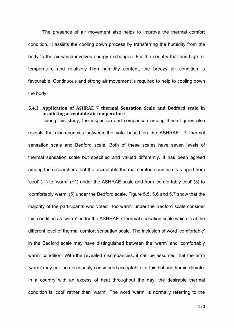
120
The presence of air movement also helps to improve the thermal comfort
condition. It assists the cooling down process by transferring the humidity from the
body to the air which involves energy exchanges. For the country that has high air
temperature and relatively high humidity content, the breezy air condition is
favourable. Continuous and strong air movement is required to help to cooling down
the body.
5.4.3 Application of ASHRAE 7 thermal Sensation Scale and Bedford scale in predicting acceptable air temperature
During this study, the inspection and comparison among these figures also
reveals the discrepancies between the vote based on the ASHRAE 7 thermal
sensation scale and Bedford scale. Both of these scales have seven levels of
thermal sensation scale but specified and valued differently. It has been agreed
among the researchers that the acceptable thermal comfort condition is ranged from
‘cool’ (-1) to ‘warm’ (+1) under the ASHRAE scale and from ‘comfortably cool’ (3) to
‘comfortably warm’ (5) under the Bedford scale. Figure 5.5, 5.6 and 5.7 show that the
majority of the participants who voted ‘ too warm’ under the Bedford scale consider
this condition as ‘warm’ under the ASHRAE 7 thermal sensation scale which is at the
different level of thermal comfort sensation scale. The inclusion of word ‘comfortable’
in the Bedford scale may have distinguished between the ‘warm’ and ‘comfortably
warm’ condition. With the revealed discrepancies, it can be assumed that the term
‘warm’ may not be necessarily considered acceptable for this hot and humid climate.
In a country with an excess of heat throughout the day, the desirable thermal
condition is ‘cool’ rather than ‘warm’. The word ‘warm’ is normally referring to the

121
heat gain which is not appreciated in this climate. This perception may have been
the cause of the difference between the previous votes based on the ASHRAE scale
and Bedford scale.
As been agreed among the researchers that the acceptable comfort air
temperature ranges from -1 to +1 under both scales, this may not be the case for the
building in this climate. With this finding, it can be predicted that by using the agreed
range to predict the thermally comfortable air temperature, it may lead to a
misleading figure. Therefore, based on the observation, it is suggested that the
maximum tolerable air temperature based on the ASHRAE scale should be at zero
(0) level which is also called ‘neutral’ temperature.
Further analysis on the votes is conducted to reveal the highest tolerable air
temperature and the relationships of the thermal comfort level with the air
Table 5. 3 - The average value of scale based on the ASHRAE and Bedford scale voted by the participants
Ambient Air
Temperature
slightly cool(-1)
neutral (0)
slightly warm
(1)
warm (2)
comfortably cool(2)
comfortable (0)
comfortably warm (1)
too warm
(2)
much too
warm
TSV scale
Comfort vote (CV)
28.7 0 2 0 0 0 0 2 0 0 0.00 0.12
29.1 0 12 5 0 0 3 11 3 0 0.29 1.00
29.4 0 16 12 0 0 8 11 9 0 0.43 1.04
29.8 0 4 22 0 0 1 11 14 0 0.85 1.50
30.2 0 0 18 1 0 0 0 19 0 1.05 2.00
30.6 0 0 11 0 0 0 3 8 0 1.00 1.45
31 0 0 3 2 0 0 2 3 0 1.40 1.20
31.4 0 0 1 5 0 0 0 6 0 1.83 2.00
31.8 0 0 0 2 0 0 0 2 0 2.00 2.00
32.2 0 0 0 3 0 0 0 3 0 2.00 2.00
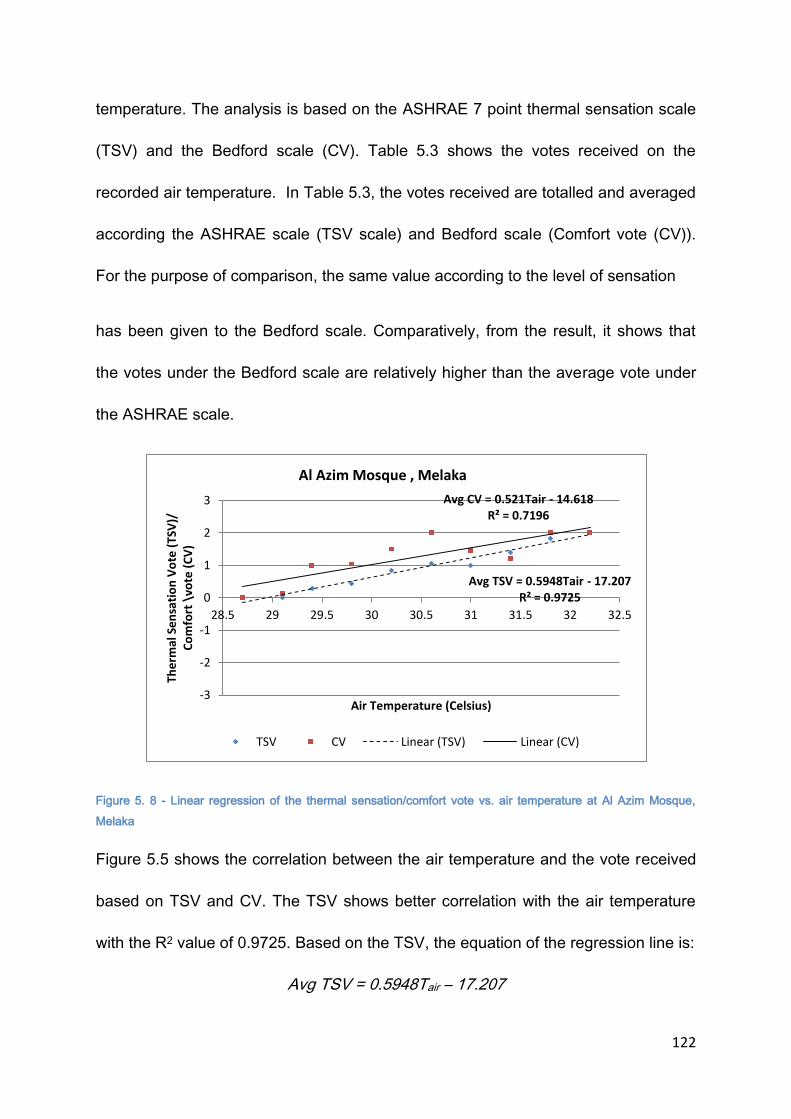
122
temperature. The analysis is based on the ASHRAE 7 point thermal sensation scale
(TSV) and the Bedford scale (CV). Table 5.3 shows the votes received on the
recorded air temperature. In Table 5.3, the votes received are totalled and averaged
according the ASHRAE scale (TSV scale) and Bedford scale (Comfort vote (CV)).
For the purpose of comparison, the same value according to the level of sensation
has been given to the Bedford scale. Comparatively, from the result, it shows that
the votes under the Bedford scale are relatively higher than the average vote under
the ASHRAE scale.
Figure 5. 8 - Linear regression of the thermal sensation/comfort vote vs. air temperature at Al Azim Mosque,
Melaka
Figure 5.5 shows the correlation between the air temperature and the vote received
based on TSV and CV. The TSV shows better correlation with the air temperature
with the R2 value of 0.9725. Based on the TSV, the equation of the regression line is:
Avg TSV = 0.5948Tair – 17.207
Avg TSV = 0.5948Tair - 17.207 R² = 0.9725
Avg CV = 0.521Tair - 14.618 R² = 0.7196
-3
-2
-1
0
1
2
3
28.5 29 29.5 30 30.5 31 31.5 32 32.5
The
rmal
Se
nsa
tio
n V
ote
(TS
V)/
C
om
fort
\vo
te (
CV
)
Air Temperature (Celsius)
Al Azim Mosque , Melaka
TSV CV Linear (TSV) Linear (CV)

123
With the equation, it can be determined that the upper limit of tolerable air
temperature (when TSV = 1) is 30.3 degree Celsius. Similarly, the regression line
from the CV vote produces:
CV = 0.521 Tair – 14.62
Using this equation, the upper limit of tolerable air temperature (when Cv = 1) is 29.4
degree Celsius which is 1 degree Celsius lower from the TSV equation.
The stronger correlation with TSV may have resulted from the precise
description of the thermal sensation based on the ASHRAE scale. Both Bedford and
ASHRAE scale are basically identical. The only difference is the addition of word
‘comfortable’ to the thermal sensation scale. As discussed earlier, the term
‘comfortable’ is more related to the psychological aspect rather than the thermal
sensation itself. Therefore, the outcome of the votes based on the Bedford scale
may have been influenced by other psychological factors. Due to this reason, it is
more precise to predict the thermal comfort condition based on thermal sensation
using the ASHRAE scale since it has stronger correlation and the thermal sensation
is clearly described. However based on the earlier finding, the range of the
acceptable thermal comfort from -1 to +1 may not be appropriate to be used for this
climate since the warm condition is interpreted as an excess of heat. Therefore, in
the case of the naturally ventilated building in the tropics, the maximum tolerable air
temperature should be based on the neutral temperature (when TSV =0). In this
case, the neutral temperature is 23.9 degree Celsius.

124
5.5 CASE STUDY 2 : JAMEK MOSQUE, SEREMBAN, MALAYSIA
Jamek Mosque, Seremban is a community mosque that can accommodate up
to 1000 people at a time. It is one of the oldest mosques that are still being used. It
has traditional characteristics with the main feature of the three tiered pitched roof.
Compared to the Al Azim mosque, the Jamek Mosque can be considered as a
smaller version of the Al Azim Mosque. A total of 131 respondents have participated
in the survey conducted in the Jamek Mosque, Seremban. Out of 131 respondents,
51 of them participate during the noon time, 31 participants during the afternoon and
49 during the evening time (Table 5.4).
5.5.1 Thermal comfort perception
Table 5.4 shows the results of the votes received on the thermal comfort
Table 5. 4 - The average, min and max for the air temperature and relative humidity according to the thermal
comfort vote and the periods of prayer time at Sikamat Mosque Seremban.
perception with the average value of the air temperature and relative humidity in
relation to the periods of time and comfort vote. Based on the votes received as
shown in the Table 5.4, the participants express that they feel acceptably
Time Too warm
Comfortabl
y warm
Comfortabl
e
No. Of
Participant Avg. Temp. Max. T Min T Avg RH Max RH Min RH
Noon 0 41% 59% 51 29 31.4 26.9 74.8 85.1 68
Afternoon 0 71% 29% 31 29.2 31.4 26.9 75.7 89.5 64.5
Evening 31% 41% 28% 49 28.9 32.2 26.5 81.5 95.5 70.3
Avg To 29.1 28.1 28.6
AvgTi 28.9 28.4 28.2
Max To 32.2 31.8 29.8
Max Ti 32.2 31.8 29.8
Min To 25.8 25.4 27.2
Min Ti 25.1 25.4 26.5
avg RH 81.2 82.1 77.5
Max 98.5 100 93
Min 70.3 64.5 68.8
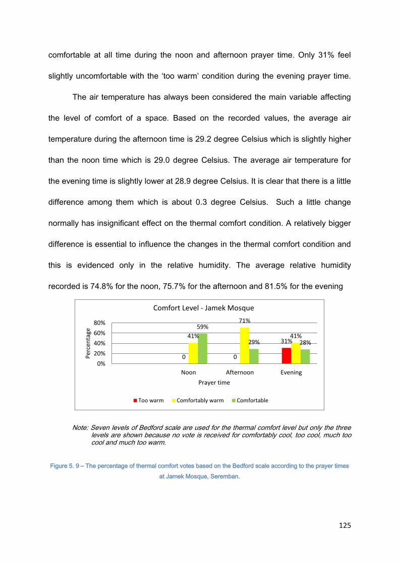
125
comfortable at all time during the noon and afternoon prayer time. Only 31% feel
slightly uncomfortable with the ‘too warm’ condition during the evening prayer time.
The air temperature has always been considered the main variable affecting
the level of comfort of a space. Based on the recorded values, the average air
temperature during the afternoon time is 29.2 degree Celsius which is slightly higher
than the noon time which is 29.0 degree Celsius. The average air temperature for
the evening time is slightly lower at 28.9 degree Celsius. It is clear that there is a little
difference among them which is about 0.3 degree Celsius. Such a little change
normally has insignificant effect on the thermal comfort condition. A relatively bigger
difference is essential to influence the changes in the thermal comfort condition and
this is evidenced only in the relative humidity. The average relative humidity
recorded is 74.8% for the noon, 75.7% for the afternoon and 81.5% for the evening
Note: Seven levels of Bedford scale are used for the thermal comfort level but only the three levels are shown because no vote is received for comfortably cool, too cool, much too cool and much too warm.
Figure 5. 9 – The percentage of thermal comfort votes based on the Bedford scale according to the prayer times
at Jamek Mosque, Seremban.
0 0
31% 41%
71%
41%
59%
29% 28%
0%
20%
40%
60%
80%
Noon Afternoon Evening
Per
cen
tage
Prayer time
Comfort Level - Jamek Mosque
Too warm Comfortably warm Comfortable

126
time. The ‘slightly uncomfortable’ votes during the evening time may have been
influenced by the increase in the relative humidity as it shows a relatively big jump
during the period of time. Figure 5.9 shows the thermal comfort perception votes in
relation to the period of time. It is shown that the ‘slightly uncomfortable’ condition is
only experienced during the evening time whereas during the noon and afternoon
time, the thermal comfort condition is considered acceptable. Based on the average
air temperature, it is obvious that the air temperature does not cause the thermal
discomfort because the average temperature recorded during this time is the lowest
among the three periods of time. As noted earlier, the substantial change occurs in
the relative humidity which is 81.5%. Being one of the main problems in thermal
comfort for tropical countries with the hot and humid climate, it is possible that the
relative humidity can cause the thermal discomfort. Analysing the coexistence of
other variables in relation to the thermal comfort perception reveals the importance
of each variable to the condition of thermal comfort level.
5.5.2 Affecting factors and preferences on thermal comfort
The following figures (Figure 5.10, 5.11 and 5.12) show the distribution of the
votes on thermal comfort perception in relation to the variables investigated such as
thermal sensation, humidity, wind condition and the preferences according to the
periods of investigation. The cross examination can justify the influence of the
variables in affecting the thermal comfort condition. Figure 5.10 represents the votes
received during the noon time. There are only two thermal comfort conditions voted
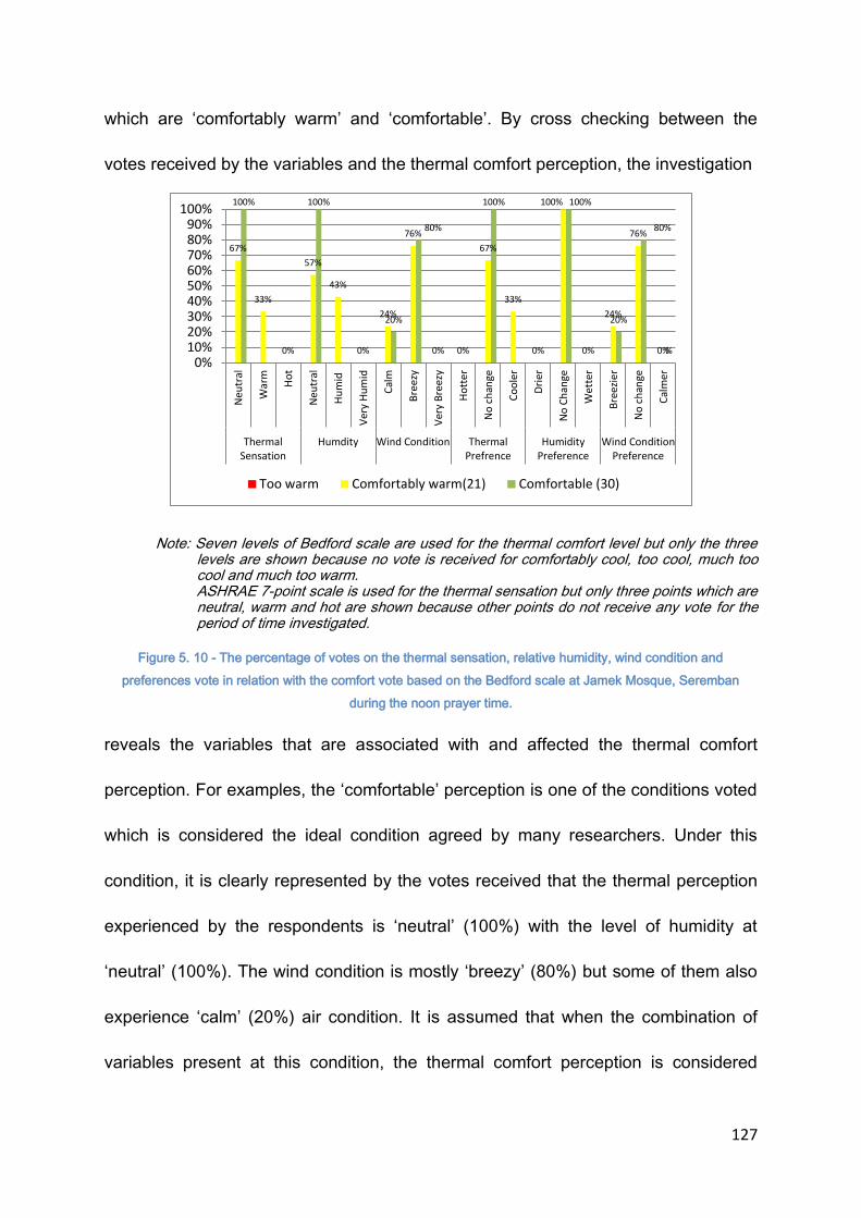
127
which are ‘comfortably warm’ and ‘comfortable’. By cross checking between the
votes received by the variables and the thermal comfort perception, the investigation
Note: Seven levels of Bedford scale are used for the thermal comfort level but only the three levels are shown because no vote is received for comfortably cool, too cool, much too cool and much too warm.
ASHRAE 7-point scale is used for the thermal sensation but only three points which are neutral, warm and hot are shown because other points do not receive any vote for the period of time investigated.
Figure 5. 10 - The percentage of votes on the thermal sensation, relative humidity, wind condition and
preferences vote in relation with the comfort vote based on the Bedford scale at Jamek Mosque, Seremban
during the noon prayer time.
reveals the variables that are associated with and affected the thermal comfort
perception. For examples, the ‘comfortable’ perception is one of the conditions voted
which is considered the ideal condition agreed by many researchers. Under this
condition, it is clearly represented by the votes received that the thermal perception
experienced by the respondents is ‘neutral’ (100%) with the level of humidity at
‘neutral’ (100%). The wind condition is mostly ‘breezy’ (80%) but some of them also
experience ‘calm’ (20%) air condition. It is assumed that when the combination of
variables present at this condition, the thermal comfort perception is considered
67%
33%
0%
57%
43%
0%
24%
76%
0% 0%
67%
33%
0%
100%
0%
24%
76%
0%
100% 100%
20%
80%
100% 100%
20%
80%
%
0%10%20%30%40%50%60%70%80%90%
100%
Neu
tral
War
m
Ho
t
Neu
tral
Hu
mid
Ver
y H
um
id
Cal
m
Bre
ezy
Ver
y B
reez
y
Ho
tte
r
No
ch
ange
Co
ole
r
Dri
er
No
Ch
ange
Wet
ter
Bre
ezie
r
No
ch
ange
Cal
mer
ThermalSensation
Humdity Wind Condition ThermalPrefrence
HumidityPreference
Wind ConditionPreference
Too warm Comfortably warm(21) Comfortable (30)

128
comfortable. Another thermal comfort perception voted is ‘comfortably warm’. Under
this condition, the thermal perception experienced is either ‘neutral’ (67%) or
‘warm’(33%) with the humidity level felt either ‘neutral’ (57%) or ‘humid’ (43%).
Along with this, it is also recorded that the air condition is mostly breezy (76%) and
only 24% of the respondents experience the air to be ‘calm’. There is no clear
indication on the coexistence of the variables that may have influenced the thermal
comfort vote. Based on the votes, there are eight possibilities of the combination of
variables that may lead to the ‘comfortably warm’ condition. However, by eliminating
the possibilities of the combination that may lead to a different thermal comfort
perception, the acceptable combination can be produced. Based on Figure 5.10, the
majority votes under ‘comfortably warm’ condition are the same with the votes under
‘comfortable’ category. It is clear that when the combination of the variables present
under this situation, the predicted thermal comfort perception is ‘comfortable’.
Therefore, by eliminating the majority votes that match the ‘comfortable’ votes, a
clear combination of variables that may lead to ‘comfortably warm’ can be predicted.
In this case, the combination is ‘warm’ thermal sensation with ‘calm’ air and ‘humid’.
Only the majority votes are chosen to be eliminated since the chances to have the
combination of the variables that matched is bigger.
The preference votes also emphasize the relevance of this elimination
method. For examples, the respondents who have voted ‘neutral’ for the variables
prefer the condition not to be changed. However, for those who feel warm, they
prefer to have a cooler air temperature and similarly, for those who have
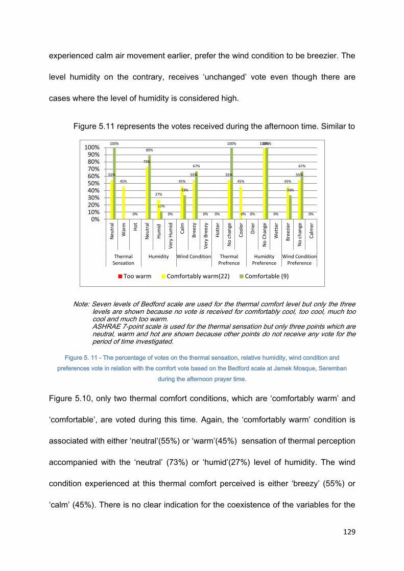
129
experienced calm air movement earlier, prefer the wind condition to be breezier. The
level humidity on the contrary, receives ‘unchanged’ vote even though there are
cases where the level of humidity is considered high.
Figure 5.11 represents the votes received during the afternoon time. Similar to
Note: Seven levels of Bedford scale are used for the thermal comfort level but only the three levels are shown because no vote is received for comfortably cool, too cool, much too cool and much too warm.
ASHRAE 7-point scale is used for the thermal sensation but only three points which are neutral, warm and hot are shown because other points do not receive any vote for the period of time investigated.
Figure 5. 11 - The percentage of votes on the thermal sensation, relative humidity, wind condition and
preferences vote in relation with the comfort vote based on the Bedford scale at Jamek Mosque, Seremban
during the afternoon prayer time.
Figure 5.10, only two thermal comfort conditions, which are ‘comfortably warm’ and
‘comfortable’, are voted during this time. Again, the ‘comfortably warm’ condition is
associated with either ‘neutral’(55%) or ‘warm’(45%) sensation of thermal perception
accompanied with the ‘neutral’ (73%) or ‘humid’(27%) level of humidity. The wind
condition experienced at this thermal comfort perceived is either ‘breezy’ (55%) or
‘calm’ (45%). There is no clear indication for the coexistence of the variables for the
55%
45%
0%
73%
27%
0%
45%
55%
0% 0%
55%
45%
0%
100%
0%
45%
55%
0%
100%
89%
11%
33%
67%
100%
0%
100%
33%
67%
0%10%20%30%40%50%60%70%80%90%
100%
Neu
tral
War
m
Ho
t
Neu
tral
Hu
mid
Ver
y H
um
id
Cal
m
Bre
ezy
Ver
y B
reez
y
Ho
tte
r
No
ch
ange
Co
ole
r
Dri
er
No
Ch
ange
Wet
ter
Bre
ezie
r
No
ch
ange
Cal
mer
ThermalSensation
Humidity Wind Condition ThermalPrefrence
HumidityPreference
Wind ConditionPreference
Too warm Comfortably warm(22) Comfortable (9)
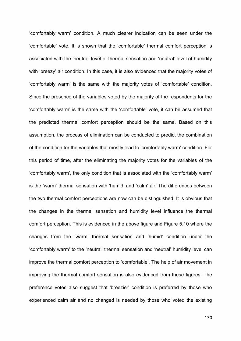
130
‘comfortably warm’ condition. A much clearer indication can be seen under the
‘comfortable’ vote. It is shown that the ‘comfortable’ thermal comfort perception is
associated with the ‘neutral’ level of thermal sensation and ‘neutral’ level of humidity
with ‘breezy’ air condition. In this case, it is also evidenced that the majority votes of
‘comfortably warm’ is the same with the majority votes of ‘comfortable’ condition.
Since the presence of the variables voted by the majority of the respondents for the
‘comfortably warm’ is the same with the ‘comfortable’ vote, it can be assumed that
the predicted thermal comfort perception should be the same. Based on this
assumption, the process of elimination can be conducted to predict the combination
of the condition for the variables that mostly lead to ‘comfortably warm’ condition. For
this period of time, after the eliminating the majority votes for the variables of the
‘comfortably warm’, the only condition that is associated with the ‘comfortably warm’
is the ‘warm’ thermal sensation with ‘humid’ and ‘calm’ air. The differences between
the two thermal comfort perceptions are now can be distinguished. It is obvious that
the changes in the thermal sensation and humidity level influence the thermal
comfort perception. This is evidenced in the above figure and Figure 5.10 where the
changes from the ‘warm’ thermal sensation and ‘humid’ condition under the
‘comfortably warm‘ to the ‘neutral’ thermal sensation and ‘neutral’ humidity level can
improve the thermal comfort perception to ‘comfortable’. The help of air movement in
improving the thermal comfort sensation is also evidenced from these figures. The
preference votes also suggest that 'breezier' condition is preferred by those who
experienced calm air and no changed is needed by those who voted the existing
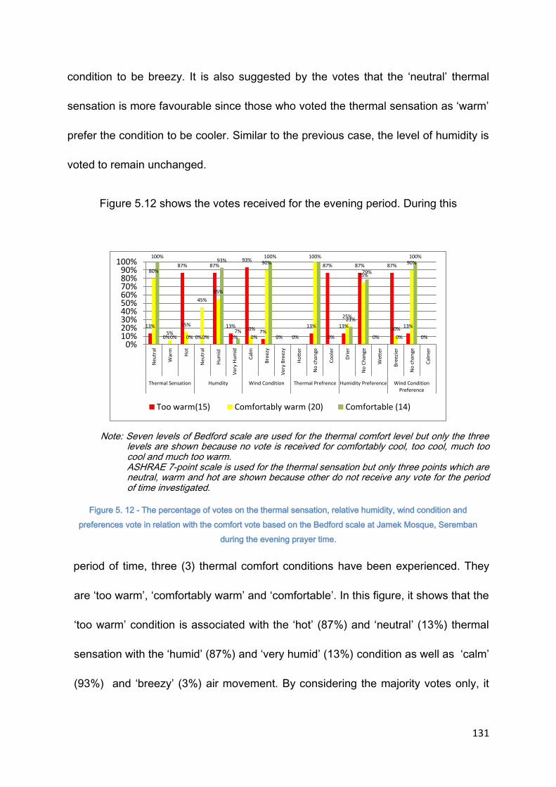
131
condition to be breezy. It is also suggested by the votes that the ‘neutral’ thermal
sensation is more favourable since those who voted the thermal sensation as ‘warm’
prefer the condition to be cooler. Similar to the previous case, the level of humidity is
voted to remain unchanged.
Figure 5.12 shows the votes received for the evening period. During this
Note: Seven levels of Bedford scale are used for the thermal comfort level but only the three levels are shown because no vote is received for comfortably cool, too cool, much too cool and much too warm.
ASHRAE 7-point scale is used for the thermal sensation but only three points which are neutral, warm and hot are shown because other do not receive any vote for the period of time investigated.
Figure 5. 12 - The percentage of votes on the thermal sensation, relative humidity, wind condition and
preferences vote in relation with the comfort vote based on the Bedford scale at Jamek Mosque, Seremban
during the evening prayer time.
period of time, three (3) thermal comfort conditions have been experienced. They
are ‘too warm’, ‘comfortably warm’ and ‘comfortable’. In this figure, it shows that the
‘too warm’ condition is associated with the ‘hot’ (87%) and ‘neutral’ (13%) thermal
sensation with the ‘humid’ (87%) and ‘very humid’ (13%) condition as well as ‘calm’
(93%) and ‘breezy’ (3%) air movement. By considering the majority votes only, it
13%
0%
87%
0%
87%
13%
93%
7% 0% 0%
13%
87%
13%
87%
0%
87%
13%
0%
80%
5%
15%
45%
55%
0%
10%
90% 100%
0%
25%
75%
10%
90% 100%
0% 0% 0%
93%
7% 0%
100%
21%
79%
0%
100%
0%10%20%30%40%50%60%70%80%90%
100%
Neu
tral
War
m
Ho
t
Neu
tral
Hu
mid
Ver
y H
um
id
Cal
m
Bre
ezy
Ver
y B
ree
zy
Ho
tter
No
ch
ange
Co
ole
r
Dri
er
No
Ch
ange
Wet
ter
Bre
ezie
r
No
ch
ange
Cal
mer
Thermal Sensation Humdity Wind Condition Thermal Prefrence Humidity Preference Wind ConditionPreference
Too warm(15) Comfortably warm (20) Comfortable (14)

132
can be determined that the ‘too warm’ condition is mostly associated with ‘hot’
thermal sensation with ‘humid’ and ‘calm’ air. It is also indicated that there is a
match between the combined majority votes for the ‘comfortable’ and ‘comfortably
warm’ votes. Assuming that when the same conditions of the variables present the
same thermal comfort perception is expected to be the same. Between the two
conditions, the choice that has higher percentage will be selected as the expected
condition. In this case, the ‘comfortable’ thermal comfort perception is selected
since the condition has higher percentage. By eliminating the votes of ‘comfortably
warm’ that has been identified to have the same conditions with the ‘comfortable’
situation, the ‘comfortably warm’ condition is now associated with either the ‘warm
or ‘hot’ thermal sensation with ‘neutral’ level of humidity and ‘calm’ air. The ‘too
warm’ thermal comfort perception is clearly associated with the ‘hot’ thermal
sensation with ‘humid’ and ‘calm’ air condition. The change from ‘comfortably warm’
to ‘too warm’ situation is therefore predicted as a result of the change in the thermal
sensation from ‘warm’ to ‘hot’ and humidity level from ‘neutral’ to ‘humid’. The
obvious difference between the ‘comfortably warm’ and ‘comfortable’ situation can
be evidenced in the wind condition. The ‘comfortable’ condition has breezy wind
condition whereas the wind condition for the ‘comfortably warm’ condition is ‘calm’
which means relatively little wind movement can be sensed.
Looking at the results obtained from three periods of time, it can be evidenced
that the thermal sensation or air temperature has always affected the thermal
comfort perception. In many cases, the ‘neutral’ level of thermal sensation has been

133
seen as the preferred condition. The ‘warm’ thermal sensation may sometimes be
accepted however it depends on the condition of other variables. Without the air
movement, this thermal sensation can become unacceptable. It has also been
evidenced in the survey that the condition of air movement plays an important role in
affecting the thermal comfort perception. In many instances, the preferred wind
condition is the ‘breezy’ condition regardless of the thermal comfort perception. The
humidity level may have its own role in affecting the thermal comfort perception,
however based on the preference vote most of the respondents choose the condition
not to be changed. One of the reasons is that the human body is not sensitive to the
level of humidity in the air. For the effect of the humidity to be sensed, the humidity
must be at the extreme condition such as too dry (below 40%) or too humid (above
80%). In many cases, the relative humidity is at the acceptable range.
5.5.3 Application of ASHRAE 7 thermal Sensation Scale and Bedford scale in predicting acceptable air temperature
Table 5. 5 - The average value of scale based on the ASHRAE and Bedford scale voted by the participants
Nvotes Tind
Slightly
cool neutral
slightly
warm warm
Tsensatio
n
comforta
bly cool
comforta
ble
comforta
bly warm too warm Cvote
11 25.4 8 3 0 0 -0.7 7 4 0 0 -0.6
7 25.8 1 6 0 0 -0.1 1 6 0 0 -0.1
4 26.1 0 4 0 0 0.0 0 0 4 0 1.0
6 26.5 0 6 0 0 0.0 0 2 2 2 1.0
9 26.9 0 9 0 0 0.0 0 5 4 0 0.4
10 27.2 0 10 0 0 0.0 0 4 6 0 0.6
12 27.6 0 11 1 0 0.1 0 6 6 0 0.5
17 27.9 0 17 0 0 0.0 0 11 6 0 0.4
6 28.3 0 6 0 0 0.0 0 3 3 0 0.5
9 28.7 0 9 0 0 0.0 0 5 4 0 0.4
14 29.1 0 14 0 0 0.0 0 8 6 0 0.4
6 29.4 0 6 0 0 0.0 0 5 1 0 0.2
3 29.8 0 3 0 0 0.0 0 2 1 0 0.3
6 30.2 0 3 3 0 0.5 0 0 6 0 1.0
6 30.6 0 3 3 0 0.5 0 6 0 0 0.0
7 31 0 0 7 0 1.0 0 7 0 0 0.0
5 31.4 0 0 3 2 1.4 0 0 3 2 1.4
8 31.8 0 0 0 8 2.0 0 0 3 5 1.6
6 32.2 0 0 0 6 2.0 0 0 0 6 2.0
ASHRAE Thermal sensation scale Bedford scale

134
As explained earlier, the ASHRAE scale is more related to the thermal
sensation rather than the thermal comfort condition and the Bedford scale is more
towards the thermal comfort level since the inclusion of the word ‘comfortable’ in the
evaluative scale. Based on the figures, it can be evidenced that when the air
temperature is below the neutral level both of the scales prediction is coherent. The
same coherency is also evidenced when the temperature is above the scale of 1.
The inconsistency occurs when the temperature is between the scale of 0 and 1. The
Bedford scale, in many cases, shows a higher scale compared to ASHRAE scale
within this range. The logical reason is that the Bedford scale is more related to the
thermal comfort level rather than just the thermal sensation itself. Thermal comfort is
dependent on many variables depending on the climate zone. For the tropical
climate, the air movement beside the air temperature is one of the major influencing
factors for the thermal comfort. The humidity content in the air is equally important
but its effect is dependent on the air temperature and wind condition. On the other
hand, the ASHRAE scale is directly related to thermal sensation which can easily be
sensed by the human body. Due to this, the inconsistency occurs between the two
scales.
Based on the votes, a linear regression is constructed for the two scales.
Figure 5.13 shows the regression line for the thermal sensation/comfort vote against
the air temperature. Due to the inconsistency of the evaluated scale to the air
temperature, the comfort vote has R2 = 0.2688 with the equation of:
Cvote = 0.1565 Tair – 3.9173

135
Figure 5. 13 - Linear regression of the thermal sensation/comfort vote vs. air temperature at Jamek Mosque,
Seremban
The thermal sensation vote based on the ASHRAE scale is more consistent and
accurate in relation to the air temperature. The linear regression produces an
equation :
Tsensation = 0.2917 Tair – 8.0329 with R2 = 0.7055
With this equation, the ‘neutral’ air temperature is predicted at 25.00 Celsius. The
maximum tolerable air temperature that has been agreed by the researchers (when
Tsensation = 1) is predicted at 31.00 Celsius.
5.6 CASE STUDY 3: MASJID QARIAH SIKAMAT, SEREMBAN, MALAYSIA
Masjid Qariah Seremban was completed in 2004 to cater for the population of
the surrounding areas. It is a complex which consists of the main building which is
the prayer hall and two supporting wings to house a library, a counseling centre,
classrooms and offices.
y = 0.2917x - 8.0329 R² = 0.7055
y = 0.1565x - 3.9173 R² = 0.2688
-3
-2
-1
0
1
2
3
24 24.5 25 25.5 26 26.5 27 27.5 28 28.5 29 29.5 30 30.5 31 31.5 32 32.5 33 33.5 34 34.5 35
The
rmal
se
nsa
tio
n V
ote
/ C
om
fort
Vo
te
Air Temperature
Air Temperature vs. Thermal Sensation Vote/Comfort Vote
Tsensation Cvote
Linear (Tsensation) Linear (Cvote)

136
The prayer hall of the mosque is square in plan and it can accommodate up to
2500 people at one time. It has a mezzanine level which covers one third of the floor
area. Around the prayer hall, a 20-foot-verandah is provided to support the overflow
of the occupants especially during the Friday prayer. From the outside, the prayer
hall is marked by a majestic dome that hovers over the prayer hall. Locating the
mosque will not be a problem because of the prominent dome structure and
furthermore accompanied by the tall minaret which is among the main elements in
the mosque design.
Between the external and the internal, the veranda, besides providing
additional spaces for praying, acts as a transitional space. The separation between
the external world and the internal space of the mosque which is considered sacred
is required in any mosque.
5.6.1 Thermal comfort perception
Figure 5.14 shows the votes collected during the three periods of the praying
times which are noon, afternoon and evening. A total of 165 participants have
responded to the questionnaire given which is about the thermal sensation they
experienced. 53 respondents participate during the noon time, 38 of them during the
afternoon and the rest of the respondents participate during the evening time. Based
on the votes received, it shows that most participants feel either ‘comfortably warm’
or ‘too warm’ during the three periods of the praying time for this mosque. Only

137
Note: Seven levels of Bedford scale are used for the thermal comfort level but only the three levels are shown because no vote is received for comfortably cool, too cool, much too cool and much too warm.
Figure 5. 14 - The percentage of thermal comfort votes based on the Bedford scale according to the
prayer times at Sikamat Mosque, Seremban
15.8% of the participants from the afternoon praying time feel comfortable during that
time. The figure also shows that more participants (54%) feel ‘too warm’ during the
evening praying time compared to the other two praying times (31.6% for the
afternoon and 22.6% for the noon).
Table 5. 6 - The average, min and max for the air temperature and relative humidity according to the thermal
comfort vote and the periods of prayer time at Sikamat Mosque Seremban.
Table 5.6 shows the average air temperature and relative humidity according to the
period of praying times and thermal sensation experienced. The average air
22.6 31.6
54
77.4
52.6 46
0
15.8
0 0
20
40
60
80
100
Noon Afternoon Evening
Comfort Condition - Sikamat Mosque
Too warm
Comfortably warm
comfortable
Time Too warm
Comfortably
warm comfortable
No. Of
Participant Avg. Temp. Max. T Min T Avg RH Max RH Min RH
Noon 22.6 77.4 0 53 28.4 30.2 26.1 73.3 83.5 63.9
Afternoon 31.6 52.6 15.8 38 29.3 31.4 26.5 74.4 85.6 64
Evening 54 46 0 74 29.4 32.2 26.5 75.9 88.1 58.7
Avg To 29.4 28.5 30.4
AvgTi 30 28.3 30.7
avg RH 73 76.3 67.1
Max To 31.4 31.8 31
Max Ti 32.2 31.8 31.4
Max RH 88.1 85.9 70.6
Min To 25.8 26.1 29.8
Min Ti 27.6 26.1 30.2
Min RH 58.7 63.4 64

138
temperature during the three periods of praying time shows small differences among
them. The average air temperature is 28.4 during the noon, 29.3 during the evening
and 29.4 during the evening. The average relative humidity during these periods of
time also shows small differences between 1.1% and 2.5%. The small differences in
relative humidity and air temperature are insignificant to determine the influential
factors affecting the difference in the thermal sensation. Looking at the ‘comfortable’
situation, it is shown that the average temperature for this situation is 30.7 degree
Celsius with the average relative humidity of 67.1%. The ‘too warm’ situation records
the average air temperature of 30.0 degree Celsius, which is lower than the
‘comfortable’ situation, with the average relative humidity of 73% which is slightly
higher than the average relative humidity of the ‘comfortable’ situation. With these
recorded values, it can be interpreted that the higher relative humidity may have
affected the participants to feel ‘too warm’. This assumption is also supported by the
data recorded for the ‘comfortably warm’ situation. The average air temperature is
28.3 degree Celsius with the average relative humidity of 76.3%. The average air
temperature is lower but the relative humidity is higher than the average air
temperature recorded for the ‘comfortable’ situation. Even though, the air
temperature recorded is lower, the respondents felt the condition is warmer and
there is a possibility that the higher relative humidity affects the thermal comfort
condition. Looking at the presence of other variables that are important in affecting
thermal comfort condition helps to justify the assumptions.

139
5.6.2 Affecting factors and preferences on thermal comfort
A cross checking on the votes received on the variables in relation to the
thermal comfort condition reveals the variables affecting the result of the level on
thermal comfort condition. Figure 5.15, 5.16, and 5.17 show the charts of the votes
received on the variables investigated during the noon, afternoon and evening time
Note: Seven levels of Bedford scale are used for the thermal comfort level but only the three levels are shown because no vote is received for comfortably cool, too cool, much too cool and much too warm.
ASHRAE 7-point scale is used for the thermal sensation but only three points which are neutral, warm and hot are shown because other points do not receive any vote for the period of time investigated.
Figure 5. 15 - The percentage of votes on the thermal sensation, relative humidity, wind
condition and preferences vote in relation with the comfort vote based on the Bedford scale
at Sikamat Mosque, Seremban during the noon prayer time.
respectively. During the noon time, only two conditions of thermal comfort situations
which are ‘comfortably warm’ and ‘too warm’. Based on the votes, all of the
respondents who felt ‘comfortably warm’ sense the thermal condition as ‘neutral’.
Along with this, 51% of them feel that the humidity level is ‘neutral’ and 49% of them
consider it as ‘humid’. At the same time, 54% of them consider the wind condition as
75%
25%
0% 0%
100%
0%
100%
0% 0% 0% 0%
100% 100%
0% 0%
100%
0% 0%
100%
51% 49% 46% 54%
17%
83%
49% 51% 46%
54%
0%10%20%30%40%50%60%70%80%90%
100%
Neu
tral
War
m
Ho
t
Neu
tral
Hu
mid
Ver
y H
um
id
Cal
m
Bre
ezy
Ver
y B
reez
y
Ho
tte
r
No
ch
ange
Co
ole
r
Dri
er
No
Ch
ange
Wet
ter
Bre
ezie
r
No
ch
ange
Cal
mer
ThermalSensation
Humidity Wind Condition ThermalPrefrence
HumidityPreference
Wind ConditionPreference
Too warm (12) Comfortably warm(41) Comfortable (0)
140
‘breezy’ and 46% experienced ‘calm’ air. It is noted that the differences between the
‘neutral’/‘humid’ and ‘calm’ / ‘breezy’ are relatively small, therefore, it is difficult to
determine the variables that are more influential in affecting the thermal comfort
condition based on the ‘comfortably warm’ category. However, based on the ‘too
warm’ category, it can be concluded that all of them who feel thermally
uncomfortable are due to the ‘calm’ and ‘humid’ condition since the majority of the
respondents consider the thermal sensation as ‘neutral’ which is the same with the
‘comfortably warm’ category. This is also supported by the preferences vote by them
which they choose the humidity level to be ‘drier’ and the wind condition to be
‘breezier’. Despite the fact that the majority of them consider the thermal sensation
as ‘neutral’, they still prefer the condition to be ‘cooler’.
The following figure (Figure 5.16) shows the results for the afternoon time.
Three categories of thermal comfort conditions which are ‘too warm’, ‘comfortably
warm’ and ‘neutral’ have been recorded during this time. As in other earlier cases,
the ‘neutral’ thermal sensation is associated with ‘comfortable’ (90%) thermal comfort
perception. At the same time, the majority of the respondents who feel ‘comfortable’
also experienced the air to be ‘humid’ (80%) and ‘breezy’ (70%). There is 30% of the
respondents who preferred the condition to be breezier and this is resulted from the
30% of the respondents who feel the air as ‘calm’. This indicates that even though
the air temperature is felt to be neutral, the movement of air is still favourable in
providing thermally comfortable environment.
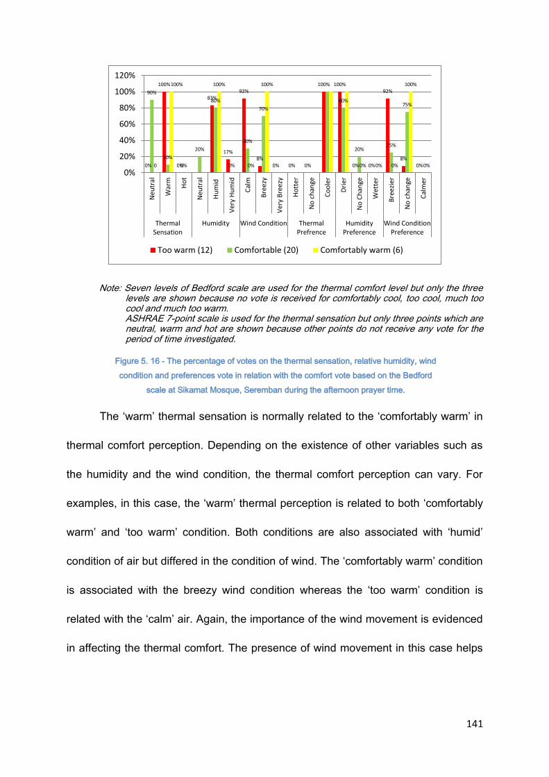
141
Note: Seven levels of Bedford scale are used for the thermal comfort level but only the three levels are shown because no vote is received for comfortably cool, too cool, much too cool and much too warm.
ASHRAE 7-point scale is used for the thermal sensation but only three points which are neutral, warm and hot are shown because other points do not receive any vote for the period of time investigated.
Figure 5. 16 - The percentage of votes on the thermal sensation, relative humidity, wind
condition and preferences vote in relation with the comfort vote based on the Bedford
scale at Sikamat Mosque, Seremban during the afternoon prayer time.
The ‘warm’ thermal sensation is normally related to the ‘comfortably warm’ in
thermal comfort perception. Depending on the existence of other variables such as
the humidity and the wind condition, the thermal comfort perception can vary. For
examples, in this case, the ‘warm’ thermal perception is related to both ‘comfortably
warm’ and ‘too warm’ condition. Both conditions are also associated with ‘humid’
condition of air but differed in the condition of wind. The ‘comfortably warm’ condition
is associated with the breezy wind condition whereas the ‘too warm’ condition is
related with the ‘calm’ air. Again, the importance of the wind movement is evidenced
in affecting the thermal comfort. The presence of wind movement in this case helps
0%
100%
0%
83%
17%
92%
8% 0% 0% 0%
100% 100%
0% 0%
92%
8% 0%
90%
10%
0%
20%
80%
0%
30%
70%
80%
20% 25%
75%
0
100% 100%
0%
100%
0% 0% 0%
100%
0%
0%
20%
40%
60%
80%
100%
120%
Neu
tral
War
m
Ho
t
Neu
tral
Hu
mid
Ver
y H
um
id
Cal
m
Bre
ezy
Ver
y B
reez
y
Ho
tte
r
No
ch
ange
Co
ole
r
Dri
er
No
Ch
ange
Wet
ter
Bre
ezie
r
No
ch
ange
Cal
mer
ThermalSensation
Humidity Wind Condition ThermalPrefrence
HumidityPreference
Wind ConditionPreference
Too warm (12) Comfortable (20) Comfortably warm (6)
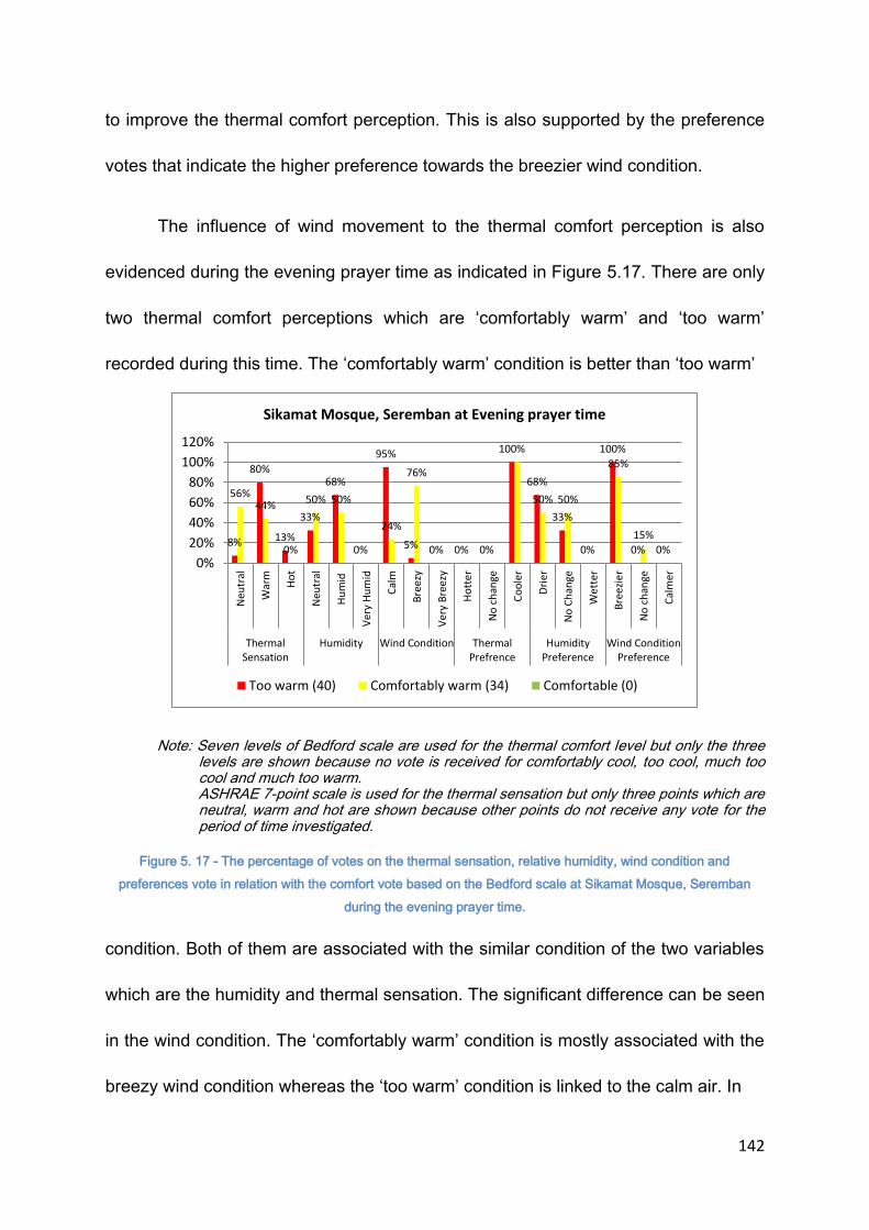
142
to improve the thermal comfort perception. This is also supported by the preference
votes that indicate the higher preference towards the breezier wind condition.
The influence of wind movement to the thermal comfort perception is also
evidenced during the evening prayer time as indicated in Figure 5.17. There are only
two thermal comfort perceptions which are ‘comfortably warm’ and ‘too warm’
recorded during this time. The ‘comfortably warm’ condition is better than ‘too warm’
Note: Seven levels of Bedford scale are used for the thermal comfort level but only the three levels are shown because no vote is received for comfortably cool, too cool, much too cool and much too warm.
ASHRAE 7-point scale is used for the thermal sensation but only three points which are neutral, warm and hot are shown because other points do not receive any vote for the period of time investigated.
Figure 5. 17 - The percentage of votes on the thermal sensation, relative humidity, wind condition and
preferences vote in relation with the comfort vote based on the Bedford scale at Sikamat Mosque, Seremban
during the evening prayer time.
condition. Both of them are associated with the similar condition of the two variables
which are the humidity and thermal sensation. The significant difference can be seen
in the wind condition. The ‘comfortably warm’ condition is mostly associated with the
breezy wind condition whereas the ‘too warm’ condition is linked to the calm air. In
8%
80%
13%
33%
68%
0%
95%
5% 0% 0% 0%
100%
68%
33%
0%
100%
0% 0%
56% 44%
0%
50% 50%
24%
76%
50% 50%
85%
15%
0%
20%
40%
60%
80%
100%
120%
Neu
tral
War
m
Ho
t
Neu
tral
Hu
mid
Ver
y H
um
id
Cal
m
Bre
ezy
Ver
y B
reez
y
Ho
tte
r
No
ch
ange
Co
ole
r
Dri
er
No
Ch
ange
Wet
ter
Bre
ezie
r
No
ch
ange
Cal
mer
ThermalSensation
Humidity Wind Condition ThermalPrefrence
HumidityPreference
Wind ConditionPreference
Sikamat Mosque, Seremban at Evening prayer time
Too warm (40) Comfortably warm (34) Comfortable (0)

143
this case, it is also noted that the ‘neutral’ thermal sensation is linked with the
‘comfortably warm’ condition and the ‘warm’ thermal sensation is linked with the ‘too
warm’ thermal perception. The inconsistencies between the thermal sensation vote
and the thermal perception vote suggest that the thermal sensation needs to be
evaluated together with other influential variables in determining the thermal comfort
perception .
5.6.3 Application of ASHRAE 7 thermal Sensation Scale and Bedford scale in predicting acceptable air temperature
The following table (Table 5.7) shows the average scale received by the
thermal sensation vote based on the ASHRAE and thermal comfort vote based on
the
Table 5. 7 - The average value of scale based on the ASHRAE and Bedford scale voted by the participants
Bedford scale. For the purpose of the comparison, the 7 scales given to the Bedford
scale has been changed to follow the ASHRAE scale. The average of the votes
received based on the two scales in relation to the measured air temperature is
No. Of
votes Tind
slightly
cool neutral
slightly
warm warm Ts
comfrtab
ly cool
comforta
ble
comforta
bly warm too warm CV
2 26.1 0 2 0 0 0.0 0 0 2 0 1.0
8 26.5 0 8 0 0 0.0 0 0 8 0 1.0
15 26.9 0 15 0 0 0.0 0 0 15 0 1.0
15 27.2 0 15 0 0 0.0 0 0 15 0 1.0
9 27.6 0 8 1 0 0.1 0 0 8 1 1.1
10 27.9 0 5 5 0 0.5 0 0 4 6 1.6
14 28.3 0 9 5 0 0.4 0 0 7 7 1.5
10 28.7 0 7 3 0 0.3 0 0 7 3 1.3
9 29.1 0 7 2 0 0.2 0 0 7 2 1.2
7 29.4 0 7 0 0 0.0 0 0 2 5 1.7
7 29.8 0 7 0 0 0.0 0 0 3 4 1.6
8 30.2 0 0 8 0 1.0 0 2 1 5 1.4
13 30.6 0 0 13 0 1.0 0 1 4 8 1.5
17 31 0 0 17 0 1.0 0 2 7 8 1.4
10 31.4 0 0 10 0 1.0 0 1 4 5 1.4
9 31.8 0 0 5 4 1.4 0 0 1 8 1.9
1 32.2 0 0 0 1 2.0 0 0 0 1 2.0

144
tabulated in Table 5. 7. Based on the average received by the ASHRAE and Bedford
scale, it is obvious that both of them are perceived differently by the respondents.
The Bedford scale, in all occasions, shows higher average readings in comparison
with the ASHRAE scale. The bigger differences can be seen when the reading is
between 0 and 1 under the ASHRAE scale. As the reading on the ASHRAE scale
increases, the differences between the two scales are becoming smaller and
eventually become the same. As discussed earlier in the earlier cases, the ASHRAE
scale evaluative description is specifically related to the thermal sensation whereas
the Bedford scale is also related to the thermal sensation scale but with the addition
of word comfortable in some of the evaluative scale. This may have changed the
perception with the inclusion of word ‘comfortable’. In the area that has warm and hot
temperature throughout the year, the influences in thermal comfort may have been
caused by other variables besides air temperature. The high heat may have become
very common and tolerable due to the process of the acclimatization and therefore
there is a possibility that higher air temperature can be considered as neutral by the
respondents in term of thermal sensation. In term of thermal comfort level, the
presence of air movement normally helps to improve the thermal comfort condition
and the high humidity often reduces the level of thermal comfort. The air temperature
or the heat by itself can be very influential if it reaches the intolerable limit. Therefore,
it is important to correctly estimating the tolerable limit. It may be different from the
suggested by the ASHRAE or Bedford scale because of different climate and culture.
From the previous observation it seem that the heat have not been seen as
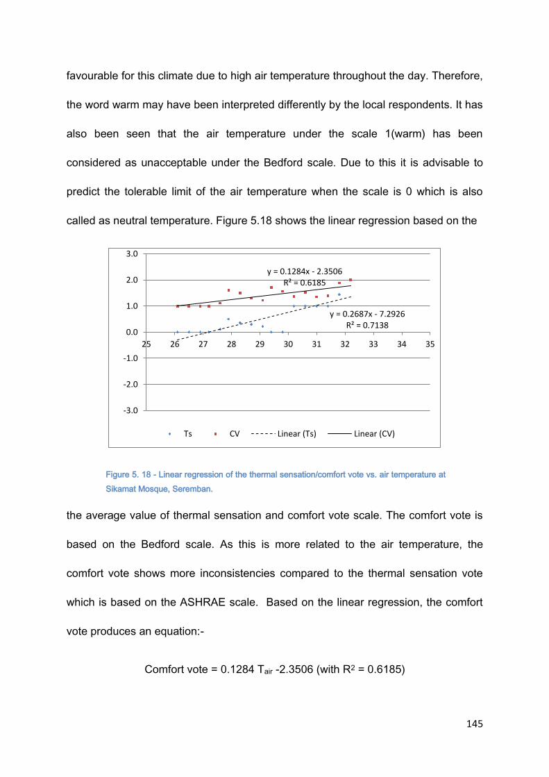
145
favourable for this climate due to high air temperature throughout the day. Therefore,
the word warm may have been interpreted differently by the local respondents. It has
also been seen that the air temperature under the scale 1(warm) has been
considered as unacceptable under the Bedford scale. Due to this it is advisable to
predict the tolerable limit of the air temperature when the scale is 0 which is also
called as neutral temperature. Figure 5.18 shows the linear regression based on the
Figure 5. 18 - Linear regression of the thermal sensation/comfort vote vs. air temperature at
Sikamat Mosque, Seremban.
the average value of thermal sensation and comfort vote scale. The comfort vote is
based on the Bedford scale. As this is more related to the air temperature, the
comfort vote shows more inconsistencies compared to the thermal sensation vote
which is based on the ASHRAE scale. Based on the linear regression, the comfort
vote produces an equation:-
Comfort vote = 0.1284 Tair -2.3506 (with R2 = 0.6185)
y = 0.2687x - 7.2926 R² = 0.7138
y = 0.1284x - 2.3506 R² = 0.6185
-3.0
-2.0
-1.0
0.0
1.0
2.0
3.0
25 26 27 28 29 30 31 32 33 34 35
Ts CV Linear (Ts) Linear (CV)

146
Based on the suggested tolerable limit using the neutral temperature it is predicted
that the neutral temperature based on the Bedford scale is 18. 30 Celsius. Using the
agreed range (when the Cv is=1), the upper limit is 26.10 Celsius. Based on the
thermal sensation scale, the linear regression produces an equation of:
Tvote = 0.2687 Tair – 7.2926 (with R2 = 0.7138)
Based on this equation, the neutral temperature is 27.140 Celsius. Based on the
agreed tolerable range which is when the Tvote = 1, the predicted air temperature is
30.860 Celsius.
The prediction using the ASHRAE scale (thermal sensation vote) is more
accurate compared to the Bedford scale. This is because the descriptive on the
ASHRAE scale is more precise in relation to the air temperature whereas the
Bedford scale is more toward the overall thermal comfort situation which may include
other variables as well. Because of that, the tolerable limit of the air temperature for
this case study is 27.140 Celsius. This air temperature is also called the ‘neutral’
temperature.
5.7 AL MIZAN MOSQUE, PUTRAJAYA
Al Mizan is the smallest mosque among the four selected mosques. It can
accommodate about 250 people at one time in the prayer hall. As described earlier
in Chapter Four, the mosque has a centralised domed roof with an open facade
design which is differ from the other mosques. A total of 114 participants are
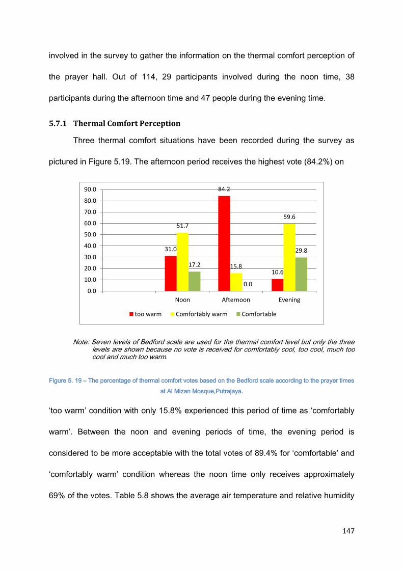
147
involved in the survey to gather the information on the thermal comfort perception of
the prayer hall. Out of 114, 29 participants involved during the noon time, 38
participants during the afternoon time and 47 people during the evening time.
5.7.1 Thermal Comfort Perception
Three thermal comfort situations have been recorded during the survey as
pictured in Figure 5.19. The afternoon period receives the highest vote (84.2%) on
Note: Seven levels of Bedford scale are used for the thermal comfort level but only the three levels are shown because no vote is received for comfortably cool, too cool, much too cool and much too warm.
Figure 5. 19 – The percentage of thermal comfort votes based on the Bedford scale according to the prayer times
at Al Mizan Mosque,Putrajaya.
‘too warm’ condition with only 15.8% experienced this period of time as ‘comfortably
warm’. Between the noon and evening periods of time, the evening period is
considered to be more acceptable with the total votes of 89.4% for ‘comfortable’ and
‘comfortably warm’ condition whereas the noon time only receives approximately
69% of the votes. Table 5.8 shows the average air temperature and relative humidity
31.0
84.2
10.6
51.7
15.8
59.6
17.2
0.0
29.8
0.0
10.0
20.0
30.0
40.0
50.0
60.0
70.0
80.0
90.0
Noon Afternoon Evening
too warm Comfortably warm Comfortable
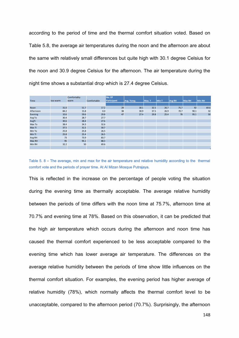
148
according to the period of time and the thermal comfort situation voted. Based on
Table 5.8, the average air temperatures during the noon and the afternoon are about
the same with relatively small differences but quite high with 30.1 degree Celsius for
the noon and 30.9 degree Celsius for the afternoon. The air temperature during the
night time shows a substantial drop which is 27.4 degree Celsius.
Table 5. 8 – The average, min and max for the air temperature and relative humidity according to the thermal
comfort vote and the periods of prayer time. At Al Mizan Mosque Putrajaya.
This is reflected in the increase on the percentage of people voting the situation
during the evening time as thermally acceptable. The average relative humidity
between the periods of time differs with the noon time at 75.7%, afternoon time at
70.7% and evening time at 78%. Based on this observation, it can be predicted that
the high air temperature which occurs during the afternoon and noon time has
caused the thermal comfort experienced to be less acceptable compared to the
evening time which has lower average air temperature. The differences on the
average relative humidity between the periods of time show little influences on the
thermal comfort situation. For examples, the evening period has higher average of
relative humidity (78%), which normally affects the thermal comfort level to be
unacceptable, compared to the afternoon period (70.7%). Surprisingly, the afternoon
Time too warm
Comfortably
warm Comfortable
No. Of
Participant Avg. Temp. Max. T Min T Avg RH Max RH Min RH
Noon 31.0 51.7 17.2 29 30.1 32.5 26.7 75.7 92 69.6
Afternoon 84.2 15.8 0.0 38 30.9 37.5 26.9 70.7 90.1 32
Evening 10.6 59.6 29.8 47 27.4 29.8 25.4 78 95.1 50
Avg To 30.4 28.7 27.7
AvgTi 30.6 28.4 27.6
Max To 38.4 34.3 32.6
Max Ti 37.5 31.5 30.7
Min To 25.8 25.8 26.5
Min Ti 25.8 25.4 26.5
Avg RH 73 73.9 83.7
Max RH 95 95.1 88.3
Min RH 32.2 50 69.6
149
period has more votes for being less thermally comfortable. It is very apparent that
the average air temperature for the evening time is the highest among the three.
There is also a possibility that the relative humidity recorded is still tolerable to the
respondents and with the low air temperature (27.4 Celsius) that is recorded during
the evening time the influence of the relative humidity at 78% may have not been
significant. The presence of air movement may have also affected the votes
recorded. A cross checking on the variables affecting the vote is necessary to
identify the causes.
5.7.2 Affecting factors and preferences on thermal comfort
Figure 5.20, 5.21 and 5.22 show the association of the variables affecting the
thermal comfort level to the thermal comfort perception of the respondents during
noon, afternoon and evening period of time respectively. Figure 5.19 shows the
votes received during the noon time. There are three thermal comfort situations
recorded during this time which are ‘too warm’, ‘comfortably warm’ and ‘comfortable’.
Along with these votes, the participants are also asked on the thermal sensation, the
humidity and the wind movement that they experienced along with these thermal
comfort sensations. By cross checking the votes received on these variables, it
reveals the variables associated with the thermal comfort sensation they

150
Note: Seven levels of Bedford scale are used for the thermal comfort level but only the three levels are shown because no vote is received for comfortably cool, too cool, much too cool and much too warm.
ASHRAE 7-point scale is used for the thermal sensation but only three points which are neutral, warm and hot are shown because other points do not receive any vote for the period of time investigated.
Figure 5. 20 - The percentage of votes on the thermal sensation, relative humidity, wind
condition and preferences vote in relation with the comfort vote based on the Bedford scale
at Al Mizan Mosque, Putrajaya during the noon prayer time.
experienced. Based on the votes received, the ‘comfortable’ situation is mostly
associated to the ‘neutral ‘ (75%) and ‘warm’ (25%) thermal sensation with either
‘humid’ (25%) or ‘very humid’ (75%) condition and ‘calm’ (75%) or ‘breezy’ (25%)
wind condition. The ‘comfortably warm’ condition is associated with the ‘warm’ (94%)
and ‘hot’ (6%) thermal sensation with the ‘humid’ (100%) condition and ‘calm’ (29%)
or ‘breezy’ (71%) air movement. The unacceptable comfort condition which is ‘too
warm’ is associated with ‘warm’ (30%) and ‘hot’ (70%) thermal sensation with either
‘humid’(50%) or ‘very humid’ (38%) condition and ‘calm’ (100%) air movement.
50% 50%
13%
50%
38%
100% 94%
6%
100%
29%
71%
100%
71%
29%
100%
75%
25% 25%
75% 75%
25% 25%
75%
100%
0%
10%
20%
30%
40%
50%
60%
70%
80%
90%
100%
Neu
tral
War
m
Ho
t
Neu
tral
Hu
mid
Ve
ry H
um
id
Cal
m
Bre
ezy
Ve
ry B
ree
zy
Ho
tter
No
ch
ange
Co
ole
r
Dri
er
No
Ch
ange
Wet
ter
Bre
ezi
er
No
ch
ange
Cal
mer
Thermal Sensation Humdity Wind Condition Thermal Prefrence Humidity Preference Wind ConditionPreference
Pe
rce
nta
ge
Thermal Comfort Factors
Al Mizan Mosque Putrajaya (Noon)
Too warm(8) Comfortably warm(17) Comfortable(4)

151
Based on these observation, it can be said that with the ‘neutral’ thermal
sensation, there is a higher possibility that the condition to be ‘comfortable’
regardless of the situation of other variables. In contrast, when the thermal sensation
is under the ‘hot’ condition, the thermal comfort condition predicted will most
probably be unacceptable as the condition becomes ‘too hot’. The ’warm’ thermal
sensation however, shows three possibilities of thermal comfort conditions
depending on other variables. The most expected thermal comfort condition when
the thermal sensation is ‘warm’ is ‘comfortably warm’. However, the graph also
indicates that for this situation to be ‘comfortably warm’, the humidity level should be
under the ‘humid’ category with the ‘breezy’ air condition. This condition can become
‘too warm’ when there is little air movement present as indicated in the graph
regardless of the humidity level. This indicates that the influence of air movement to
the thermal comfort level is significant and it is reflected in the preferences’ votes
where all participants would like the condition to be breezier regardless of how
thermally comfortable they experienced. For the preferences’ votes on the thermal
sensation, the majority of the participants would like the condition to be cooler
including for those who voted the thermal sensation to be ‘neutral’. For humidity, the
actual condition that most of the participants experienced is either ‘humid’ or ‘very
humid’ and as for the preferences, the participants would prefer the condition to be
drier.

152
The next figure (Figure 5.21) shows the votes received during the afternoon
time. Similar to the situation at the noon time, three conditions of thermal comfort
situations which are’ comfortable’, ‘comfortably warm’, and ‘too warm’ have been
Note: Seven levels of Bedford scale are used for the thermal comfort level but only the three levels are shown because no vote is received for comfortably cool, too cool, much too cool and much too warm.
ASHRAE 7-point scale is used for the thermal sensation but only three points which are neutral, warm and hot are shown because other points do not receive any vote for the period of time investigated.
Figure 5. 21- The percentage of votes on the thermal sensation, relative humidity, wind condition and
preferences vote in relation with the comfort vote based on the Bedford scale at Al Mizan Mosque, Putrajaya
during the afternoon prayer time
recorded. The ‘comfortable’ situation is again associated with the ‘neutral’ thermal
sensation. It is also shown that along with this thermal sensation, the humidity level
experienced by the respondents who voted the situation as ‘comfortable’ is either
‘very humid’ (92%) or ‘humid’ (8%) and the wind conditions is considered either
‘breezy’ (83%) or ‘calm’ (17%). It seems that the presence of high humidity does not
affect the ‘comfortable’ situation. One of the possibilities is because the thermal
100% 100% 100% 100% 100% 100%
10%
43% 48%
14%
29%
57%
38%
62%
29%
71%
57%
43%
100%
8%
92%
17%
83%
100%
8%
92%
0%10%20%30%40%50%60%70%80%90%
100%
Neu
tral
War
m
Ho
t
Neu
tral
Hu
mid
Ver
y H
um
id
Cal
m
Bre
ezy
Ver
y B
reez
y
Ho
tte
r
No
ch
ange
Co
ole
r
Dri
er
No
Ch
ange
Wet
ter
Bre
ezie
r
No
ch
ange
Cal
mer
ThermalSensation
Humdity WindCondition
ThermalPrefrence
HumidityPreference
WindCondition
Preference
Pe
rce
nta
ge
Thermal Comfort Factors
Al Mizan Mosque, Putrajaya (Afternoon)
Too warm(5) Comfortably warm(21) Comfortable(12)
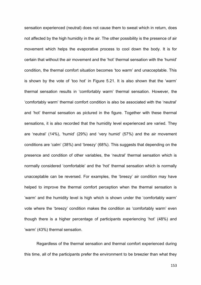
153
sensation experienced (neutral) does not cause them to sweat which in return, does
not affected by the high humidity in the air. The other possibility is the presence of air
movement which helps the evaporative process to cool down the body. It is for
certain that without the air movement and the ‘hot’ thermal sensation with the ‘humid’
condition, the thermal comfort situation becomes ‘too warm’ and unacceptable. This
is shown by the vote of ‘too hot’ in Figure 5.21. It is also shown that the ‘warm’
thermal sensation results in ‘comfortably warm’ thermal sensation. However, the
‘comfortably warm’ thermal comfort condition is also be associated with the ‘neutral’
and ‘hot’ thermal sensation as pictured in the figure. Together with these thermal
sensations, it is also recorded that the humidity level experienced are varied. They
are ‘neutral’ (14%), ‘humid’ (29%) and ‘very humid’ (57%) and the air movement
conditions are ‘calm’ (38%) and ‘breezy’ (68%). This suggests that depending on the
presence and condition of other variables, the ‘neutral’ thermal sensation which is
normally considered ‘comfortable’ and the ‘hot’ thermal sensation which is normally
unacceptable can be reversed. For examples, the ‘breezy’ air condition may have
helped to improve the thermal comfort perception when the thermal sensation is
’warm’ and the humidity level is high which is shown under the ‘comfortably warm’
vote where the ‘breezy’ condition makes the condition as ‘comfortably warm’ even
though there is a higher percentage of participants experiencing ‘hot’ (48%) and
‘warm’ (43%) thermal sensation.
Regardless of the thermal sensation and thermal comfort experienced during
this time, all of the participants prefer the environment to be breezier than what they

154
have had experienced. For those who voted the thermal sensation to be ‘neutral’,
they prefer not to change the thermal sensation. However, the majority of
participants who voted for ‘warm’ and ‘hot’ prefer the condition to be cooler. For the
humidity level, the majority of the participants who voted the thermal comfort
condition as ‘too hot’ and ‘comfortably warm’ prefer the humidity level to be drier. For
those who voted for ‘comfortable’ prefer the condition to be unchanged despite many
of them feel that the humidity level is ‘very humid’. The presence of the humidity in
the air is difficult to be sensed. The indication that there is a high humidity on the air
is through the amount of sweat accumulated on the skin. In many cases, the
presence of high humidity does not influence the thermal comfort condition when the
thermal sensation is low or at the neutral level. The presence of air movement, in
some cases, also lessens the effect of humidity to the thermal comfort sensation.
The next figure (Figure 5.22) represents the vote received during the evening time.
Only two thermal comfort conditions recorded during this time. They are the
‘comfortably warm’ and ‘comfortable’ condition. The major difference between these
two votes is on the thermal sensation experience. The majority of participants who
voted for the ‘comfortably warm’ thermal comfort condition experiences ‘warm’ (90%)
thermal sensation, whereas the majority of the participant who voted for ‘comfortable’
option experience ‘neutral’(89%) thermal sensation. Based on the votes, the
‘comfortable’ situation is also associated with the ‘neutral’ (15%) and ‘humid’ (85%)
condition. The condition of wind during this period of time is mostly ‘breezy’ (74%)
and ‘calm’ (26%). Similarly, besides the ‘warm’ thermal sensation, the ‘comfortably

155
warm’ condition is also associated with the ‘neutral’ (45%) level of humidity and
‘humid’ (55%) condition with the ‘breezy’ (85%) and ‘ calm’ (15%) wind condition.
Note: Seven levels of Bedford scale are used for the thermal comfort level but only the three levels are shown because no vote is received for comfortably cool, too cool, much too cool and much too warm.
ASHRAE 7-point scale is used for the thermal sensation but only three points which are neutral, warm and hot are shown because other points do not receive any vote for the period of time investigated.
Figure 5. 22 – The percentage of votes on the thermal sensation, relative humidity, wind condition and
preferences vote in relation with the comfort vote based on the Bedford scale at Al Mizan Mosque, Putrajaya
during the evening prayer time.
Based on the rules of the majority, it can be predicted that in most cases,
even though the condition of air is ‘humid’ the participants still feel ‘comfortable’
when the thermal sensation is at the ‘neutral’ level. The ‘breezy’ air condition that
has been felt by 74% of the respondents during this time may have improved the
thermal comfort condition but according to the preferences votes, the majority of the
respondents who feel comfortable prefer the condition of air movement to be
unchanged (56%) and the other 44% of the respondents prefer breezier wind
10%
90%
0%
45% 55%
0%
15%
85%
0% 0%
70%
30%
55% 45%
0%
50% 50%
0%
89%
11% 15%
85%
26%
74%
96%
4%
85%
15%
44%
56%
0%10%20%30%40%50%60%70%80%90%
100%N
eutr
al
War
m
Ho
t
Neu
tral
Hu
mid
Ver
y H
um
id
Cal
m
Bre
ezy
Ver
y B
reez
y
Ho
tte
r
No
ch
ange
Co
ole
r
Dri
er
No
Ch
ange
Wet
ter
Bre
ezie
r
No
ch
ange
Cal
mer
ThermalSensation
Humdity Wind Condition ThermalPrefrence
HumidityPreference
Wind ConditionPreference
Pe
rce
nta
ge
Thermal Comfort Factors
Al Mizan Mosque, Putrajaya (Evening)
Too warm(0) Comfortably warm(20) Comfortable(27)

156
condition. Almost all participants which is about 96% of them vote to maintain the
existing ‘neutral’ thermal sensation but prefer the air condition to be drier (85%).
Similarly, when the thermal comfort condition is considered ‘comfortably
warm’, about 90% of the respondents experience ‘warm’ thermal sensation with 55%
of them feels the air condition as ‘humid’. The other 45% of them feel that the level of
humidity during that time as ‘neutral’. It is also recorded that the wind condition
experienced by the majority of respondents is ‘breezy’ (85%) which may have
assisted them to feel more thermally comfortable. Even though the respondents feel
‘warm’, only 30% of them prefer the thermal condition to be cooler with the majority
of them which is 70% wants the thermal condition to be maintained. Despite the fact
that the majority of them feel the wind condition is breezy, about 50% of them prefer
the condition to be breezier with the other 50% favour the condition to remain.
5.7.3 Application of ASHRAE 7 thermal Sensation Scale and Bedford scale in predicting the acceptable air temperature
Table 5.9 shows the votes received under the ASHRAE and Bedford scales and the
average scale based on the votes. A linear regression based on the average scale is
established for both of the scales as shown in Figure 5.23. Based on the regression
made, it can be seen that the thermal sensation scale (Tsv) based on the ASHRAE
scale is more linearly related to the air temperature compared to the Bedford scale.
Based on the regression, the equation produced under the ASHRAE scale is:
TSV = 0.27755Tair – 7.2602 (with R2 = 0.9083)
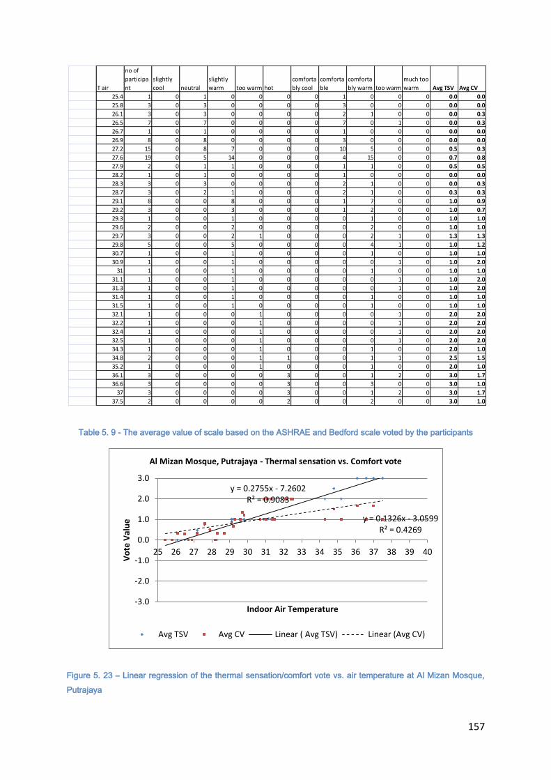
157
Table 5. 9 - The average value of scale based on the ASHRAE and Bedford scale voted by the participants
Figure 5. 23 – Linear regression of the thermal sensation/comfort vote vs. air temperature at Al Mizan Mosque,
Putrajaya
T air
no of
participa
nt
slightly
cool neutral
slightly
warm too warm hot
comforta
bly cool
comforta
ble
comforta
bly warm too warm
much too
warm Avg TSV Avg CV
25.4 1 0 1 0 0 0 0 1 0 0 0 0.0 0.0
25.8 3 0 3 0 0 0 0 3 0 0 0 0.0 0.0
26.1 3 0 3 0 0 0 0 2 1 0 0 0.0 0.3
26.5 7 0 7 0 0 0 0 7 0 1 0 0.0 0.3
26.7 1 0 1 0 0 0 0 1 0 0 0 0.0 0.0
26.9 8 0 8 0 0 0 0 3 0 0 0 0.0 0.0
27.2 15 0 8 7 0 0 0 10 5 0 0 0.5 0.3
27.6 19 0 5 14 0 0 0 4 15 0 0 0.7 0.8
27.9 2 0 1 1 0 0 0 1 1 0 0 0.5 0.5
28.2 1 0 1 0 0 0 0 1 0 0 0 0.0 0.0
28.3 3 0 3 0 0 0 0 2 1 0 0 0.0 0.3
28.7 3 0 2 1 0 0 0 2 1 0 0 0.3 0.3
29.1 8 0 0 8 0 0 0 1 7 0 0 1.0 0.9
29.2 3 0 0 3 0 0 0 1 2 0 0 1.0 0.7
29.3 1 0 0 1 0 0 0 0 1 0 0 1.0 1.0
29.6 2 0 0 2 0 0 0 0 2 0 0 1.0 1.0
29.7 3 0 0 2 1 0 0 0 2 1 0 1.3 1.3
29.8 5 0 0 5 0 0 0 0 4 1 0 1.0 1.2
30.7 1 0 0 1 0 0 0 0 1 0 0 1.0 1.0
30.9 1 0 0 1 0 0 0 0 0 1 0 1.0 2.0
31 1 0 0 1 0 0 0 0 1 0 0 1.0 1.0
31.1 1 0 0 1 0 0 0 0 0 1 0 1.0 2.0
31.3 1 0 0 1 0 0 0 0 0 1 0 1.0 2.0
31.4 1 0 0 1 0 0 0 0 1 0 0 1.0 1.0
31.5 1 0 0 1 0 0 0 0 1 0 0 1.0 1.0
32.1 1 0 0 0 1 0 0 0 0 1 0 2.0 2.0
32.2 1 0 0 0 1 0 0 0 0 1 0 2.0 2.0
32.4 1 0 0 0 1 0 0 0 0 1 0 2.0 2.0
32.5 1 0 0 0 1 0 0 0 0 1 0 2.0 2.0
34.3 1 0 0 0 1 0 0 0 1 0 0 2.0 1.0
34.8 2 0 0 0 1 1 0 0 1 1 0 2.5 1.5
35.2 1 0 0 0 1 0 0 0 1 0 0 2.0 1.0
36.1 3 0 0 0 0 3 0 0 1 2 0 3.0 1.7
36.6 3 0 0 0 0 3 0 0 3 0 0 3.0 1.0
37 3 0 0 0 0 3 0 0 1 2 0 3.0 1.7
37.5 2 0 0 0 0 2 0 0 2 0 0 3.0 1.0
y = 0.2755x - 7.2602 R² = 0.9083
y = 0.1326x - 3.0599 R² = 0.4269
-3.0
-2.0
-1.0
0.0
1.0
2.0
3.0
25 26 27 28 29 30 31 32 33 34 35 36 37 38 39 40
Vo
te V
alu
e
Indoor Air Temperature
Al Mizan Mosque, Putrajaya - Thermal sensation vs. Comfort vote
Avg TSV Avg CV Linear ( Avg TSV) Linear (Avg CV)
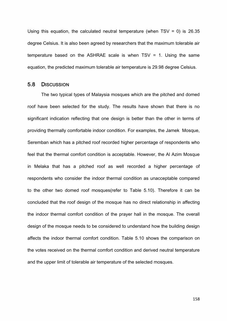
158
Using this equation, the calculated neutral temperature (when TSV = 0) is 26.35
degree Celsius. It is also been agreed by researchers that the maximum tolerable air
temperature based on the ASHRAE scale is when TSV = 1. Using the same
equation, the predicted maximum tolerable air temperature is 29.98 degree Celsius.
5.8 DISCUSSION
The two typical types of Malaysia mosques which are the pitched and domed
roof have been selected for the study. The results have shown that there is no
significant indication reflecting that one design is better than the other in terms of
providing thermally comfortable indoor condition. For examples, the Jamek Mosque,
Seremban which has a pitched roof recorded higher percentage of respondents who
feel that the thermal comfort condition is acceptable. However, the Al Azim Mosque
in Melaka that has a pitched roof as well recorded a higher percentage of
respondents who consider the indoor thermal condition as unacceptable compared
to the other two domed roof mosques(refer to Table 5.10). Therefore it can be
concluded that the roof design of the mosque has no direct relationship in affecting
the indoor thermal comfort condition of the prayer hall in the mosque. The overall
design of the mosque needs to be considered to understand how the building design
affects the indoor thermal comfort condition. Table 5.10 shows the comparison on
the votes received on the thermal comfort condition and derived neutral temperature
and the upper limit of tolerable air temperature of the selected mosques.
159
Pitched Domed
Al Azim (State) Jamek Mosque
(Community)
Sikamat Mosque
(District)
Al Mizan Mosque
(Local Community)
Acceptable Unacceptable Acceptable Unacceptable Acceptable Unacceptable Acceptable Unacceptable
Noon 49% 51% 100% 0 77% 23% 69% 31%
Afternoon 37% 63% 100% 0 68% 32% 16% 84%
Evening 39% 61% 69% 31% 46% 54% 89% 11%
Neutral
Temperature
(at '0' scale)
23.9 25.0 27.1 26.4
Upper limit
Temperature
(warm – at '1' scale)
30.3 31.0 30.9 30.0
Table 5. 10 – Comparison on the acceptable and unacceptable thermal comfort condition among the mosques.
Based on the percentages recorded it shows that the state mosque which is the
biggest mosque among the four mosques has the largest percentage of respondents
who feel the space as thermally unacceptable. It follows by the second largest
mosque which is the district mosque, the local community mosque which is the
smallest mosque and finally the community mosque. The least acceptable thermal
comfort condition occurs in the biggest mosque and the thermal comfort condition
improves as the size of the mosques becomes smaller. However, in this study, the
community mosque (Jamek Mosque) which is the second smallest and has a pitched
roof design recorded the best acceptance on thermal comfort level. This indicates
that a bigger mosque has bigger chances to be less acceptable in terms of thermal
comfort and the design of the roof and the size may have a relationship in affecting
the thermal comfort condition.
160
The size of the space designed is crucial in influencing the indoor thermal
comfort condition. A typical prayer hall space is square in plan. Therefore, the
increment in the floor area is proportionately related with the distance between the
walls that make up the space. As the floor area increases, the distance between the
walls that provide the openings also increases. For a naturally ventilated building, the
distance between the outlets and inlets is important in influencing the thermal
comfort condition of the space. With the increment in the distance between the walls
that provide the outlets and inlets for the air changes, the cross ventilation that helps
to improve the thermal comfort condition has become less effective causing less
exchanges to occur between the inside and the outside. As a result, the replacement
of hot air with the cold air cannot happen effectively causing the accumulation of
heated air inside the space. The spaces that are farther than the openings are the
areas that are mostly affected. This problem causes worse effect during the evening
prayer time (between 7 pm and 10 pm). During this time, the outdoor air temperature
reduces faster compared to the indoor air temperature due to the trapped air. With
the lower air temperature of the outdoor, the users are able to sense the higher
temperature of the indoor. This action psychologically and physically activates the
reaction towards the excess of heat experienced causing them to sweat. With the
trapped air, the humidity in the air cannot be released to the outside due to the
cooler air temperature and higher relative humidity. The evaporative process from
the sweat that is supposed to cool down the body cannot take place and in returns,
causes the feeling of ‘stuffiness’ which leads to thermally uncomfortable condition.
161
An open facade building is one of the ways of allowing the air changes to occur
effectively. This is evidenced in one of the mosques. It has an open facade prayer
hall which allows the exchanges between the outdoor and indoor to happen
uninterruptedly. The evening prayer time has been experienced by the respondents
to be the most comfortable period of time which is in contrast with other mosques.
Under this condition, the indoor thermal comfort condition is heavily dependent on
the outdoor climatic condition. If the outdoor climatic condition were under the
tolerable range, the indoor thermal comfort condition should be the same due to the
effective changes of air between the inside and the outside. However, this open
facade concept becomes a disadvantage when the outdoor air temperature is
beyond the tolerable range. The high air temperature affects the thermal comfort
level when the temperature reaches beyond the tolerable limit.
Therefore, determining the tolerable limit is important in providing the accurate
estimation to be used in many applications regarding the thermal comfort level. The
PMV method which is based on the ASHRAE scale has been widely used in
predicting the thermal comfort level of the indoor space. It has been agreed that the
acceptable range of thermally acceptable comfort condition is between -1 and 1
under the PMV calculation. Based on the ASHRAE thermal sensation scale, the
range falls between ‘cool’ and ‘warm’ scale. The use of the PMV and ASHRAE scale
has been found by many researches to be inaccurate in predicting the thermal
comfort condition for naturally ventilated building especially a building that is located
in a tropical climate. This study has also revealed that there is a discrepancy

162
between the thermal sensation under the ASHRAE scale and Bedford scale. It has
been found that the ‘warm’ scale under the ASHRAE is not always evaluated as the
same with the ‘comfortably warm’ under the Bedford scale even though it is intended
to be the same. The culture of the local people may have influenced the perception
of the terms.
As explained by Hedge in his notes, thermal sensation and thermal comfort
are not the same. Thermal sensation is closely related to the way the skin senses
the heat. On the other hand, the thermal comfort is influenced by psychological
elements which may involve other variables besides air temperature. The addition of
the word ‘comfort’ in Bedford scale has the potential of influencing the perception.
The perception of the word ‘warm’ to this community too is different when it is
compared with the classification under the Bedford scale. In many cases, the ‘warm’
situation which is considered tolerable and acceptable has not always resulted in
‘comfortably warm’ under the Bedford scale. It often relates to the ‘too warm’
condition which becomes intolerable. This situation occurs in most cases when the
air movement is sensed to be little. This implies that the ‘warm’ description of thermal
sensation scale cannot be used as the upper limit of tolerable air temperature for this
tropical region. In a tropical region, the nature of the climate is humid and hot. The
content of humidity in the air is always at the high level throughout the day. The
increase in the air temperature from the tolerable limit is capable of creating very
thermally uncomfortable condition. When the body senses the excess of heat, the
sweating reaction will start and the accumulation of sweat on the skin due to the its
163
inability to evaporate because of high content of humidity in the air causes the
person to feel uncomfortable. There is an occasion where the warm condition can be
acceptable with the presence of continuous air movement. However it is a risk to use
the ‘warm’ (or 1) as the tolerable limit.
Based on the findings, when the thermal sensation is at the ‘neutral’ level,
regardless of the conditions of other variables, the majority of the respondents feel
thermally comfortable. The use of the air temperature or thermal sensation besides
other variables as a guide in providing thermal comfort is very appropriate. It is the
only thermal comfort variable that is also related to the building design. For
examples, the building elements such as walls and roofs control the heat transferred
to the interior space. The design of the openings is intended to provide natural
ventilation which also influences the air temperatures of the interior. Other variables,
such as, humidity is strongly dependent on the condition of air. The humidity by itself
is insignificant in influencing the thermal comfort. Due to the importance of the air
temperature in influencing thermal comfort, a practical tolerable air temperature
should be provided as a measuring stick in evaluating the performance of the
building. As pointed earlier, the air temperature at the ‘neutral’ (0) level provides
thermal comfort sensation and should be used as the maximum ‘expected’ air
temperature for a building. The presence of other variables can be ignored when this
air temperature is achieved. Table 5.11 shows the ‘neutral’ air temperature and the
air temperature at scale 1. The ‘neutral’ temperature recorded for the mosques
selected ranges from 23.9 degree Celsius to 27.1 which give the average of 25.6

164
degree Celsius. This figure could be used as the attempted indoor air temperature
for any naturally ventilated mosque to ensure the thermal comfort condition can be
achieved at all time.
Even though the air temperature plays a dominant role in affecting thermal
comfort, the presence and importance of other variables must be acknowledged too.
Corrective measurement can be made if the attempted temperature cannot be met.
According to the study, the air movement has been considered as a major
‘corrective’ variable to many unfavourable thermal comfort conditions.
The study has revealed that in most of the cases, regardless of the thermal
sensation condition, the breezy wind condition is favourable. In some cases where
the thermal sensation is considered neutral, the air movement in the space is still
favourable. This indicates that the neutral temperature that has been considered
comfortable can be improved if the air movement is present. There is a possibility
that the neutral temperature may not be the same as the neutral temperature defined
under the PMV. It has also been discovered that the thermal discomfort is mostly
due to the little air movement that can be sensed by the body. Without the strong
wind movement, the replacement of the liquid (sweat) from the body is unable to
occur causing the accumulation of heat which causes thermal discomfort. With the
presence of strong and continuous wind movement, the high air temperature can be
tolerated. The strong and continuous air movement helps in speeding up the
evaporative process in cooling down the body. Without the aid of the strong wind, the
165
evaporative process cannot happen naturally due to the high content of humidity in
the air.
The presence of high humidity in the air causes the evaporative process to
slow down. It is difficult to sense the presence of the humidity in the air. One of the
ways to know whether the humidity level is high or low is through the accumulation of
sweat on the skin. The high accumulation of the sweat on the skin reflects the high
humidity level in the air which refrain the sweat to evaporate to the air. In this
research, the level of sweating is utilised in estimating the level of humidity since the
presence of the humidity in the air cannot be easily sensed by the human body as
compared to thermal sensation. As a result of this, it is not surprising to see that
many of the respondents prefer the humidity to be maintained when they are asked
about their preference on the humidity.
5.9 CONCLUSION
The investigation using the survey and field measurement on the thermal
comfort perception among the mosque users in Malaysia has revealed that they feel
thermally comfortable when the temperature is between 23.90 Celsius and 27.10
Celsius which is called the neutral temperature. At this range, it can be assumed that
the influence of other variables such as humidity and air movement does not affect
the thermal comfort perception. Humidity, however, will become effective in
influencing the thermal comfort perception after the air temperature exceeds the
neutral temperature. Air movement, on the other hand, is always desirable

166
regardless of the situation. The presence of air movement, however can improve the
thermal comfort perception especially when the air temperature and relative humidity
is higher.
The case studies have also shown that the application of thermal sensation
scale based on the ASHRAE scale is still questionable in predicting thermal comfort
level for a naturally ventilated building in a hot and humid country such as Malaysia.
The range that is agreed by many researchers as acceptable cannot be applied for a
naturally ventilated building in this type of climate. The 'warm' sensation that is
sometime desirable for a temperate climate can be sensed as an excess heat for the
people of the tropical climate country. Therefore, it is possible that the thermal
condition they experienced is not the same as the people in the temperate climate.
Based on the observation done, for prediction based on the PMV scale, instead of
using scale '1' as the maximum tolerable range, scale '0' which is also known as
‘neutral’ temperature is suggested to be used as the maximum tolerable range for
this type of climate. There is no minimum range that can be predicted from the case
studies since there is no occurrence that the air temperature is below the neutral
level or cooler.
In addition to this, it has also been revealed that there is no direct relationship
between thermal comfort level and the roof design. However, there is a possibility
that the design of the roof and the size of the building may have a connection with

167
the thermal comfort level of the space. Further investigation on the influence of the
design to the thermal condition inside the space is explained in the next chapter.

168
CHAPTER 6 – RESULTS AND DISCUSSION: HTB2 and
WinAir4 Simulation
6.1 Introduction
Chapter 6 presents and discusses the results from the simulation conducted
based on the two typical mosque designs in Malaysia which are the pitched roof and
domed roof mosque using the software called HTB2 and WinAir4 developed by
Cardiff University. The purpose of the simulation is to investigate the thermal
condition inside the prayer hall resulted from the use of the two common roof
designs which are the pitched roof and domed roof mosques. The results from the
two modelled buildings are compared in order to determine which roof type produces
better indoor thermal environment, and therefore thermal comfort level, under the
same state of outdoor condition. The previous chapter presents and discusses the
results based on the conducted survey on thermal comfort perception of the four
selected mosques representing the two typical mosque designs in Malaysia. In this
chapter, the results from the simulation process using the said software on both
designs are analysed and compared. The analysis and comparison are based on the
focus areas described later in the chapter. Based on the analysis and comparison,
conclusion on which roof design performs better in providing thermally comfortable
space for the tropical climate such as Malaysia is delivered.

169
6.2 The simulation
As discussed earlier in the Chapter 4, two typical mosque designs which are
pitched and domed roof mosques are modelled for the simulation. Both of the
designs are differed mainly on the roof design which includes materials and other
characteristics resulted from the design such as materials and volume. The
simulation was run for the period of ten days with the allowance of three days for the
space to heat up. The first part of the analysis based on the simulation is to
determine the selection of data for the investigation. Not all of the data can be used
due to the process of heating up the building that needs to take place before the air
temperature inside the building becomes stabilised. To ensure the reliability of the
results, the considered data should be opted from the period when the building
reaches the ‘steady’ or ‘balance’ condition. This is the condition where the internal
thermal condition of the building has become consistent due to the completed
process of heating up the space. This is the stage where the variables from the
outdoor can directly influence the heating and cooling process of the indoor spaces
without major interferences from other factors. The condition will change if the
outside condition is changed.
Figure 6.1 shows the pattern of the air temperature produced for the domed
mosque model for the duration of ten days allowing the heating up process to take
place for the first two days. Figure 6.2 shows the pattern for the pitched roof model
for the same duration of time. In the domed mosque simulation (Figure 6.1), it is
observed that the air temperature of the space becomes fairly constant depending

170
on the outdoor temperature after day 6. This means that the process of heating up
Figure 6.1- Changes of air temperature pattern of a domed roof mosque
Figure 6. 2- Changes of air temperature pattern of the pitched roof mosque at 30 degree, 45 degree and
60 degree pitch.
the space takes approximately about 6 days before it stabilizes. On the other hand,
the air temperature inside the pitched roof mosque (Figure 6.2) becomes fairly
constant as early as after day 3.This means that the heating up process for a pitched
roof mosque completed after day 3. Based on this observation and the notion that
the relevant data that need to be used is the data after the stabilization process, the
20.022.024.026.028.030.032.034.036.038.040.0
0.0
06
.00
12
.00
18
.00
0.0
06
.00
12
.00
18
.00
0.0
06
.00
12
.00
18
.00
0.0
06
.00
12
.00
18
.00
0.0
06
.00
12
.00
18
.00
0.0
06
.00
12
.00
18
.00
0.0
06
.00
12
.00
18
.00
0.0
06
.00
12
.00
18
.00
0.0
0
Time
Dome - Changes of air temperature without ventilation (Day 3 to 10)
Outside Temperature Inside Temperature
22242628303234363840424446
0.0
0
7.0
0
14
.00
21
.00
4.0
0
11
.00
18
.00
1.0
0
8.0
0
15
.00
22
.00
5.0
0
12
.00
19
.00
2.0
0
9.0
0
16
.00
23
.00
6.0
0
13
.00
20
.00
3.0
0
10
.00
17
.00
0.0
0
7.0
0
14
.00
21
.00
Tem
pe
ratu
re (
cels
ius)
Time
Pitched Roof - Changes of air temperature without ventilation (Day 3 to 10)
outside T 30 deg 45 deg. 60 deg
171
data accumulated after day 6 for both of these modelled mosques can be used for
the comparative analysis. However, for the purpose of the study, the results obtained
from the day seven and eight are chosen because the pattern of the outdoor air
temperature at this time reflected the typical outdoor temperatures of Malaysia and
the results from the simulation process have also shown that the patterns of heat
gain and loss are very closed to the typical pattern of heat gain and loss in a typical
mosque under a typical outdoor climate.
As explained earlier, the simulation conducted is aiming to investigate the
performance of both mosque roof designs in controlling the indoor thermal condition
which is mostly based on air temperature. In pursuing this aim, the study is divided
into focussed areas which are:
6.2.1 The relationship between the infiltration rate and heat gain and loss
Naturally ventilated buildings are designed to allow or promote the air
exchanges between the indoor and outdoor to occur due to the natural forces. As a
result, the indoor air temperature for naturally ventilated buildings is heavily
dependent on the outdoor air temperature and therefore, the determination for the
areas of opening allowing the air to flow into and out of the indoor space is important
in controlling the indoor air temperature. For a building in a tropical country, it is a
typical problem for the indoor air temperature to be higher than the outdoor air
temperature. One of the strategies suggested to control the indoor thermal comfort
condition is to maintain the indoor air temperature below the outdoor air temperature,

172
especially when the outdoor air temperature exceeds the limit of tolerable air
temperature. If a naturally ventilated building is capable in maintaining this condition,
it can be considered that the building is efficient enough in filtering the heat from the
outside into the inside.
Based on the simulation runs for the domed mosque using HTB2 software,
the pattern of heating and cooling process for both of the modelled mosques are
observed. Figure 6.3 shows the changes of air temperature inside the prayer hall of
a typical dome mosque in relation to the changes of the infiltration rate which is
defined by the area of the openings provided.
Note: Infiltration rate is the flow rate of outside air in volume into a building which is also known as the air exchange rate. It is based on the number of air exchanges occurred per hour. The 0.7/h of air changes per hour (ACH) is used when the window area is 10% of the floor area and 1.4/h of ACH is
when the window area is 20% of the floor area.
Figure 6. 3- The heat gain-loss pattern (changes of air temperature) according to the infiltration rate of 1.4/h
and 0.7/h and with no ventilation for the dome mosque
20212223242526272829303132333435
0.0
0
2.0
0
4.0
0
6.0
0
8.0
0
10
.00
12
.00
14
.00
16
.00
18
.00
20
.00
22
.00
0.0
0
2.0
0
4.0
0
6.0
0
8.0
0
10
.00
12
.00
14
.00
16
.00
18
.00
20
.00
22
.00
0.0
0
Tem
pe
ratu
re (
Ce
lsiu
s)
Time
HTB2 Simulation: Dome- Air Temperature in the Prayer Hall with different Infiltration Rate
outside temperature air temperature- 0.7
air temperature- 1.4 air temperature-no vent.

173
For the purpose of the study, two sizes of opening are selected. The first design has
a total opening of 10% of the total floor area for the undisturbed flow of air which is
the minimum area required according to the Uniform Building of By-Laws of Malaysia
1984. For the purpose of comparison, another design that has 20% of the floor area
for the opening area is also established. Based on the 10% and 20% of undisturbed
opening area in relation to the floor area, the calculated infiltration rates are 0.7/h
ACH and 1.4/h ACH respectively. Using these values, a simulation is conducted to
record the air temperature of the spaces investigated. Figure 6.3 shows that the
indoor air temperature inside the prayer hall is closer to the outdoor air temperature
with a difference of about 1 degree Celsius when the infiltration rate is higher (1.4/h
ACH). This suggests that bigger openings will produce the same indoor air
temperature as the outdoor air temperature since bigger openings allow effective air
exchanges between the inside and outside. The next figure (Figure 6.4) shows
the changes of the indoor space air temperature in relation to the outdoor air
temperature using the infiltration rate of 1.4/h ACH.
It is also observed that during most of the daytime (between 10 a.m. to 6 p.m.)
the indoor air temperature is maintained below the outdoor air temperature. This
means that the heat is successfully filtered by the building elements throughout the
period even though it is a naturally ventilated building, resulting in a lower air
temperature compared to the outside temperature. Maintaining the indoor
temperature below the outdoor temperature is crucial in providing the thermal
comfort condition especially when the outdoor temperature is above the tolerable
174
limit. With the opening that permit the infiltration rate of 1.4 ACH, it is proven that the
domed mosque roof is capable of maintaining the indoor temperature during this
period of time (from 10 a.m. to 8 p.m.).
The pattern, however, changed after this period of time. It is recorded that
between 8 p.m. until 10.00 p.m., the indoor air temperature becomes higher than the
outdoor air temperature. This is the period of time when outdoor starts to cool down.
When the outdoor temperature starts to cool down, the indoor temperature starts to
fall down as well but at a slower rate compared to the outdoor. This may be due to
the slower exchanges of air between the inside and outside. The size of the opening
may not be enough to allow the exchange of the air from the inside to the outside
leaving the indoor air temperature to be higher than the outdoor. As a result, during
this period of time, the air temperature of the indoor space is always higher than the
outdoor temperature. This condition can become undesirable because it leads to the
feeling of thermally uncomfortable due to a significant difference of air temperature
between the inside and outside. Referring to Figure 6.3, the period of this condition
occurs between approximately 7.00 pm until10. 00 pm where the air temperature
recorded is above the acceptable air temperature (above 280 C). The humidity in the
air may have also played its role in affecting thermal comfort during this time. It is
also expected that when the air temperature reduces, the relative humidity rises.
With this situation, it adds more to the thermal discomfort due to the inability for the
sweat to evaporate due to the high content of humidity in the air. This creates the
feeling of stuffiness.

175
For the pitched roof mosque, the simulated results show fairly the same
pattern with the domed mosque. Figure 6.4 shows the air temperature and mean
radiant temperature inside the prayer hall of a modelled pitched roof for day 7 and 8.
Figure 6. 4- The air temperature and mean radiant temperature of the prayer hall for the 45 degree pitch
The simulated results show that the indoor air temperature for the pitched roof
mosques is maintained below the outdoor air temperature especially during the
daytime when the tolerable air temperature is exceeded. The significant difference
between the pitched and domed roof mosque that can be observed is that the
pitched roof mosque cools faster than the domed roof. As a result, the air
temperature inside the pitched roof is cooler than the domed roof mosque during the
cooling down process which is between 6.00 p.m. and 7.00 a.m. This situation will
allow the indoor air temperature to be below than the outdoor temperature at almost
all the time.
20212223242526272829303132333435
0.0
0
2.0
0
4.0
0
6.0
0
8.0
0
10
.00
12
.00
14
.00
16
.00
18
.00
20
.00
22
.00
0.0
0
2.0
0
4.0
0
6.0
0
8.0
0
10
.00
12
.00
14
.00
16
.00
18
.00
20
.00
22
.00
0.0
0
Tem
pe
ratu
re (
Ce
lsiu
s)
Time
HTB2 Simulation:Pitched Roof- 45 degree
Outside Temperature Space Air Temperature MRT

176
As suggested by earlier researchers, a good naturally ventilated building
should be able to maintain the indoor air temperature to be lower than the outdoor air
temperature. In addition to this, it should also be able to cool down quickly to ensure
the thermal comfort condition can be achieved. It has been observed from the study
that both of these roof designs are capable of maintaining the indoor temperature
below the outdoor air temperature as suggested by the researchers. However, the
pitched roof mosque has the advantage of the ability to cool down faster compared
to the domed mosque. This ability may have been resulted from the form and design
itself. Further analysis is conducted on the next section. Based on that notion, it can
be concluded that the pitched roof mosque performs better than the domed roof
mosque.
6.2.2 Roof Space vs. Prayer Hall
One of the features suggested by Lin in order to reduce the heat gain inside a
naturally ventilated building is to provide a roof space. In many mosque designs in
Malaysia, a roof space has become one of the features incorporated into the design.
For a mosque, this roof space is commonly covered either with the dome shape roof
or a pitched roof. The simulation conducted on the pitched and domed roof mosques
shows that the roof spaces provided by the domed roof and pitched roof act
differently. Figure 6.5 and 6.6 show the recorded simulated results on the domed
and the pitched roof mosques respectively. In this investigation the overall prayer
hall space is divided into two sections which are the roof space encompassing the
space below the specialised roof design and the prayer hall space encompassing the

177
rest of the space. A virtual layer of separation is placed in between the space which
allows the natural act of heat transfer to occur according to the temperature
differences as suggested by the HTB2 manual.
For the case of the domed roof (Figure 6.5), it is observed from the graph that
the air temperature for both spaces which are the roof and prayer hall increases as
Figure 6. 5 - The space air temperature of the roof space and prayer hall in the domed mosque
the outdoor temperature increases. It is also noted that the rate of heating up the air
temperature is fairly the same between the roof space and the prayer hall. However,
the air temperature for the prayer hall is always maintained below the outdoor
temperature especially during the heating up process, whereas the air temperature
for the roof space is either almost the same or higher than the outdoor air
temperature. It is calculated that the difference between the air temperature for the
roof and prayer hall space is calculated at about 1 degree Celsius or less throughout
the day.
202122232425262728293031323334353637383940
0.0
0
2.0
0
4.0
0
6.0
0
8.0
0
10
.00
12
.00
14
.00
16
.00
18
.00
20
.00
22
.00
0.0
0
2.0
0
4.0
0
6.0
0
8.0
0
10
.00
12
.00
14
.00
16
.00
18
.00
20
.00
22
.00
0.0
0
Tem
pe
ratu
re (
Ce
lsiu
s)
Time
HTB2 Simulation: Dome- Prayer Hall with roof Space - Space air Temperature
outside temperature air temperature- Prayer Hall air temperature- Roof Space

178
Figure 6. 6- The comparison of the space air temperature between the roof space and the
prayer hall in the pitched roof mosque
For the pitched roof (Figure 6.6), the air temperature for both of the spaces
increases when the outdoor temperature rises and similarly reduces when the
outdoor air temperature cools down. However, based on the simulation, it can be
seen that the air temperature in the roof space is heated up and cooled down faster
than the air temperature of the prayer hall making a huge difference in air
temperature between the two areas during the peak time. The recorded difference
for the air temperature in the roof space and the prayer hall is between 1 degree
Celsius and 5 degree Celsius depending on the period of time.
Figure 6.7 shows the comparison between the air temperature inside the
prayer hall of the domed and pitched roof mosque. Comparing the two results, it
shows that the space air temperature for the prayer in both of the mosque designs is
slightly varied in the air temperature depending on the time of the day with the
202122232425262728293031323334353637383940
0.0
0
2.0
0
4.0
0
6.0
0
8.0
0
10
.00
12
.00
14
.00
16
.00
18
.00
20
.00
22
.00
0.0
0
2.0
0
4.0
0
6.0
0
8.0
0
10
.00
12
.00
14
.00
16
.00
18
.00
20
.00
22
.00
0.0
0
Tem
pe
ratu
re
time
HTB2 Simulation:Pitched Roof with Roof space
Outdoor Temperature Prayer Hall Temperature Roof Space Temperature

179
Figure 6. 7 - The comparison between the domed and pitched roof mosque
on the space air temperature of the prayer hall
average of less than two degree Celsius difference. In all cases, the air temperature
of the prayer hall spaces is always lower for the pitched roof mosque compared to
the domed roof mosque. This may have resulted from the ability of the pitched roof
mosque to cool down faster compared to the domed roof mosque as discussed in
the previous section.
Figure 6. 8 - The comparison between the pitched and domed roof on the roof space air temperature
20212223242526272829303132333435
0.0
0
2.0
0
4.0
0
6.0
0
8.0
0
10
.00
12
.00
14
.00
16
.00
18
.00
20
.00
22
.00
0.0
0
2.0
0
4.0
0
6.0
0
8.0
0
10
.00
12
.00
14
.00
16
.00
18
.00
20
.00
22
.00
0.0
0
HTB2 Simulation - Comparison of the air temperature of prayer hall between dome and pitch with separate roof space and space
air temperature
Tout Tpray Tpray(pitch)
202122232425262728293031323334353637
0.0
0
2.0
0
4.0
0
6.0
0
8.0
0
10
.00
12
.00
14
.00
16
.00
18
.00
20
.00
22
.00
0.0
0
2.0
0
4.0
0
6.0
0
8.0
0
10
.00
12
.00
14
.00
16
.00
18
.00
20
.00
22
.00
0.0
0
HTB2 Simulation - Comparison between dome and pitch with separate roof space - roof space temperature
Tout Dome Pitch

180
Figure 6.8 shows the air temperature of the roof space for the domed and
pitched roof modelled mosques. From the simulation, it can be observed that the
heating and cooling pattern for the roof space of the domed and pitched roof is not
similar with the pattern observed at the prayer hall space. From the graph, it can be
evidenced that the air temperature of the roof space for the pitched roof mosque is
significantly higher than the domed roof mosque especially during the peak time of
heating. Inversely, the air temperature for the pitched roof mosque is significantly
lower than the domed roof mosque during the cooling process. This condition results
in a bigger difference between the air temperature of the roof space and the prayer
hall for the pitched roof mosque. However, a smaller difference of less than one (1)
degree Celsius is recorded for the domed roof mosque.
Natural ventilation can happen through two means which are cross ventilation
and stack effect ventilation. As discussed in Chapter 2, stack effect ventilation is
caused due to the significant difference of air temperature between the lower and
upper part of a space, whereas, cross ventilation occurs due to the difference in
pressure which may be resulted from the forces of air movement. Referring to this
theory, the significant difference of the air temperature between the two levels of the
spaces is seen to be beneficial in helping to improve the natural ventilation inside the
space. In this study, it has been shown that the air temperature inside the roof space
of the pitched roof mosque is significantly higher than the domed roof mosque, and if
compared with the difference of the air temperature between the roof space and the
prayer hall of the domed roof mosque, the difference is relatively small. With this
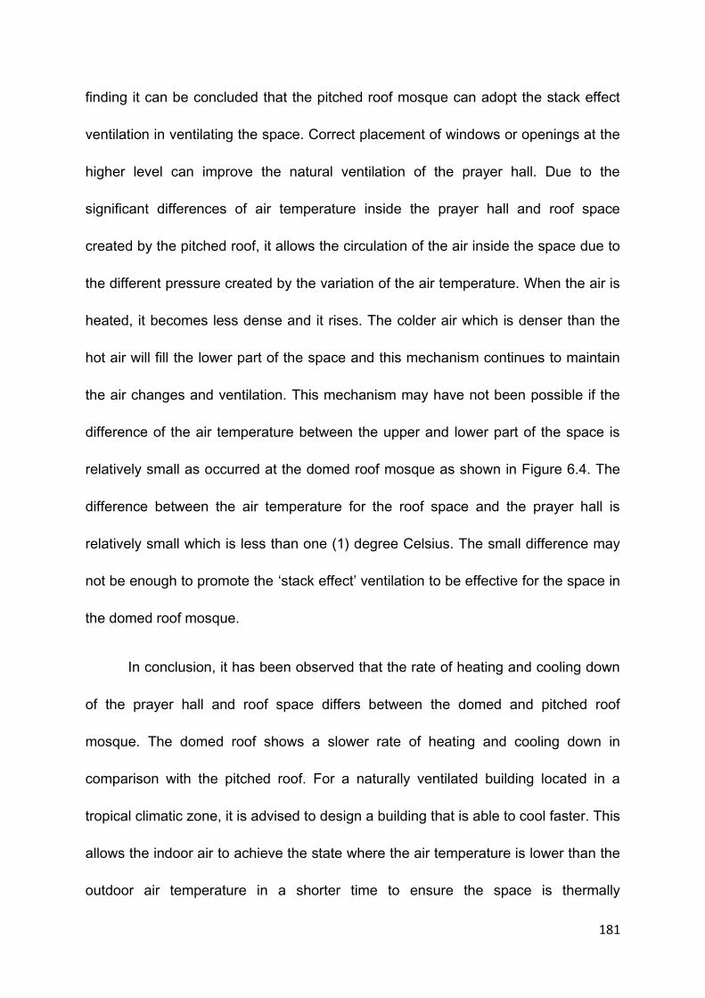
181
finding it can be concluded that the pitched roof mosque can adopt the stack effect
ventilation in ventilating the space. Correct placement of windows or openings at the
higher level can improve the natural ventilation of the prayer hall. Due to the
significant differences of air temperature inside the prayer hall and roof space
created by the pitched roof, it allows the circulation of the air inside the space due to
the different pressure created by the variation of the air temperature. When the air is
heated, it becomes less dense and it rises. The colder air which is denser than the
hot air will fill the lower part of the space and this mechanism continues to maintain
the air changes and ventilation. This mechanism may have not been possible if the
difference of the air temperature between the upper and lower part of the space is
relatively small as occurred at the domed roof mosque as shown in Figure 6.4. The
difference between the air temperature for the roof space and the prayer hall is
relatively small which is less than one (1) degree Celsius. The small difference may
not be enough to promote the ‘stack effect’ ventilation to be effective for the space in
the domed roof mosque.
In conclusion, it has been observed that the rate of heating and cooling down
of the prayer hall and roof space differs between the domed and pitched roof
mosque. The domed roof shows a slower rate of heating and cooling down in
comparison with the pitched roof. For a naturally ventilated building located in a
tropical climatic zone, it is advised to design a building that is able to cool faster. This
allows the indoor air to achieve the state where the air temperature is lower than the
outdoor air temperature in a shorter time to ensure the space is thermally

182
comfortable. The pitched roof has the ability to cool down faster allowing longer time
for the air temperature to heat up. In addition to this, it is also been observed that the
distinctive temperature difference between the roof space and the prayer hall in the
pitched roof mosque can be benefited in promoting natural ventilation.
6.2.3 Mean Radiant Temperature
Mean Radiant Temperature (MRT) has been considered as one of the important
factors affecting the thermal comfort condition of a space. The significant differences
between the ambience air temperature and the MRT can affect the thermal comfort
perception of the occupants. MRT is the average temperature felt by the user,
resulted from the surface temperature around the space. The MRT is directly related
to the heat transferred by the surfaces of the space. Because of this, the spaces
that are exposed directly to the sun play an important role in radiating the heat from
the sun to the inside space. It is important to determine the elements of a building
that are highly contributed to the MRT in order to strategise actions to improve the
thermal comfort condition of the space.
The simulation using the HTB2 is conducted to obtain the result on the MRT
produced by the surrounding surfaces of the prayer hall and the roof space. The
simulated results based on the pitched and the domed roof mosques are plotted to
analyse the building elements that are most affected by the sun. Figure 6.9 shows
the result from the simulation run under the domed roof mosque. Based on the
simulated results, it is shown that the MRT of the roof space is higher in comparison
with the MRT of the prayer hall. The differences ranging from 1 degree Celsius to

183
about 6 degree Celsius is recorded throughout the day and the differences become
greater as the building cools down. The material and the construction of the surfaces
may have played a bigger role in influencing the MRT of the spaces. For examples,
the roof space for the dome roof is made of concrete which has the ability to store
Figure 6. 9 - The Mean Radiant Temperature at the roof space and prayer hall of the domed roof mosque
the heat for a longer time. With this property, the concrete dome takes longer time to
transfer the heat absorbed to the indoor space during the heating up process.
Depending on the climate, this ability may be an advantage as it stores the heat
before releasing it to the space. As the space is heated up according to the changes
of the outdoor air temperature, the heat releases from the roof surfaces is minimised
due to the property that concrete has. This reduces the sensation of heat felt by the
users of the space. With this property, the concrete dome roof also takes longer time
to cool down. This may affect the thermal comfort level especially during the cooling
down process of the building. This is the situation when the outdoor air temperature
202122232425262728293031323334353637383940
0.0
0
2.0
0
4.0
0
6.0
0
8.0
0
10
.00
12
.00
14
.00
16
.00
18
.00
20
.00
22
.00
0.0
0
2.0
0
4.0
0
6.0
0
8.0
0
10
.00
12
.00
14
.00
16
.00
18
.00
20
.00
22
.00
0.0
0
Tem
pe
ratu
re (
Ce
lsiu
s)
Time
HTB2 Simulation: Dome- Prayer Hall with roof Space - Mean Radiant Temperature
outside temperature MRT- Prayer Hall MRT - Roof Space

184
is cooler than the indoor air temperature. For a hot and humid country, it is always
thermally comfortable to enter a space that is cooler than the outdoor. The ability to
store heat may become disadvantage during this period of time where the heat
absorbed is now released to the interior as the air temperature cools down. The air
temperature for this climate has small diurnal range and therefore, the cooling down
of the temperature often does not even reach the suggested thermally comfortable
air temperature. This situation can become worse because as the air temperature
reduces, normally the relative humidity rises. With the release of the heat from the
surfaces of the dome and the high content of humidity in the air, the thermal comfort
level may not be achieved.
Contrastingly, the MRT of the prayer hall which is resulted mainly from the
walls surrounding the area increases and reduces at a faster rate compared to the
MRT of the roof space but at the same time the heat generated is always lower
compared to the MRT of the roof surfaces. This indicates that the wall surfaces
transfer less heat to the interior spaces compared to the roof surfaces. One of the
reasons is that the wall surfaces of the mosque are mostly shadowed by the large
overhangs of the roof and not directly exposed to the sun. There is less direct
sunlight hits the wall and therefore less heat transmitted resulting in lower MRT. In
addition to this, most of the materials used for the wall construction are made of
timber which has lower value of transmitting heat energy.

185
Based on the observation, it can be assumed that the roof is a critical
element to be considered in designing a domed mosque as it transmitted a lot of
heat into the indoor space. The roof has the longest exposure time to the direct
sunlight compared to the walls. The selection of the materials and construction
types for the roof are very important in designing as it has bigger influence to the
thermal comfort level inside the building. The wall may not play such an important
role in influencing the indoor thermal condition by the means of transmitting the
heat energy to the interior space as most of the time, the wall is shadowed by the
large overhangs provided by the roof elements. Therefore, the selection of the
material is less critical for the wall.
A different pattern of mean radiant temperature has been recorded for the
pitched roof mosque. Figure 6.10 shows the pattern of the mean radiant temperature
Figure 6. 10 – Mean Radiant Temperature for the Prayer Hall and Roof Space of Pitched Roof Mosque
20222426283032343638404244464850
0.0
0
2.0
0
4.0
0
6.0
0
8.0
0
10
.00
12
.00
14
.00
16
.00
18
.00
20
.00
22
.00
0.0
0
2.0
0
4.0
0
6.0
0
8.0
0
10
.00
12
.00
14
.00
16
.00
18
.00
20
.00
22
.00
0.0
0
Tem
pe
ratu
re
Time
HTB2 Simulation:Pitched Roof with Roof Space-MRT
Outdoor Temperature
Prayer Hall Mean Radiant Temperature
Roof Space Mean Radiant Temperature

186
for the roof and prayer hall spaces under the pitched roof. It is recorded that the
differences between 1 degree Celsius and more than 7 degree Celsius can be
observed between the MRT of the roof space and the prayer hall space. The
differences of the MRT recorded between the space become greater as the building
heats up and the differences is at the maximum point when the building reaches the
highest temperature. Based on this simulation results, it is clearly shown that the
MRT for the roof space of the pitched roof is significantly higher than the MRT of the
prayer hall itself.
In this study, the effect of having the different degrees of the pitched roof is
also investigated. Figure 6.11 shows the air temperature originated from the different
Figure 6.11- The comparison of the air temperature for the different degrees of pitch roof
degrees of the pitched roof. The three types of the slope degrees normally use in the
pitched construction is 30, 45 and 60 degrees. Based on the simulation, the
differences in the degree of the pitch do not have any influence to the space air
20212223242526272829303132333435
0.0
0
2.0
0
4.0
0
6.0
0
8.0
0
10
.00
12
.00
14
.00
16
.00
18
.00
20
.00
22
.00
0.0
0
2.0
0
4.0
0
6.0
0
8.0
0
10
.00
12
.00
14
.00
16
.00
18
.00
20
.00
22
.00
0.0
0Tem
pe
ratu
re (
Ce
lsiu
s)
Time
HTB2 Simulation:Pitched Roof- Space Air Temperature
Outside Temperature Space Air Temperature 45 degree
Space Air Temperature 60 degree Space Air Temperature 30 degree
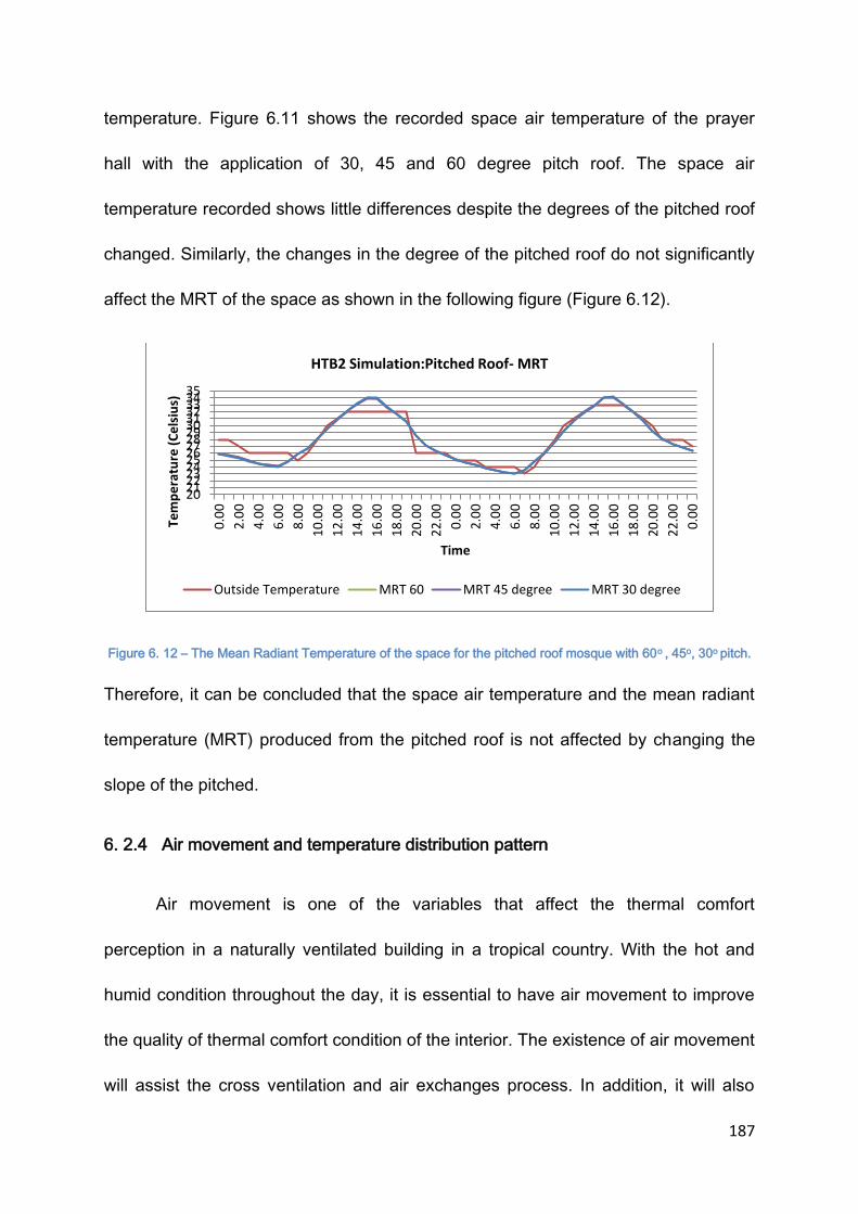
187
temperature. Figure 6.11 shows the recorded space air temperature of the prayer
hall with the application of 30, 45 and 60 degree pitch roof. The space air
temperature recorded shows little differences despite the degrees of the pitched roof
changed. Similarly, the changes in the degree of the pitched roof do not significantly
affect the MRT of the space as shown in the following figure (Figure 6.12).
Figure 6. 12 – The Mean Radiant Temperature of the space for the pitched roof mosque with 60o , 45o, 30o pitch.
Therefore, it can be concluded that the space air temperature and the mean radiant
temperature (MRT) produced from the pitched roof is not affected by changing the
slope of the pitched.
6. 2.4 Air movement and temperature distribution pattern
Air movement is one of the variables that affect the thermal comfort
perception in a naturally ventilated building in a tropical country. With the hot and
humid condition throughout the day, it is essential to have air movement to improve
the quality of thermal comfort condition of the interior. The existence of air movement
will assist the cross ventilation and air exchanges process. In addition, it will also
20212223242526272829303132333435
0.0
0
2.0
0
4.0
0
6.0
0
8.0
0
10
.00
12
.00
14
.00
16
.00
18
.00
20
.00
22
.00
0.0
0
2.0
0
4.0
0
6.0
0
8.0
0
10
.00
12
.00
14
.00
16
.00
18
.00
20
.00
22
.00
0.0
0
Tem
pe
ratu
re (
Ce
lsiu
s)
Time
HTB2 Simulation:Pitched Roof- MRT
Outside Temperature MRT 60 MRT 45 degree MRT 30 degree

188
help the body to cool down through the process of evaporation of the sweat
produced. As discussed earlier, there are two passive methods that can be
employed to assist the movement of air of the interior space of the building. They are
‘cross’ ventilation which is based on the pressure condition between the outlet and
the inlet and ‘stack effect’ ventilation which is dependent on the vertical air
temperature differences. The software WinAir4 is employed to assist in inquiring the
patterns of the air movement for both types of mosques. The software will be able to
show the distribution pattern of air movement and temperature.
Figure 6.13 shows the distribution pattern of air movement and temperature
inside the modelled domed roof mosque at 0.25 meter high from the floor level. This
Figure 6. 13 – Air movement and temperature pattern in a prayer hall of a dome mosque – horizontal view.
is the sitting down level or the level where the activities took place. Six openings
which are the doors to the prayer hall are opened to allow the air to move into the
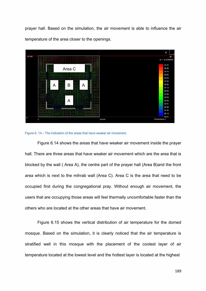
189
prayer hall. Based on the simulation, the air movement is able to influence the air
temperature of the area closer to the openings.
Figure 6. 14 – The indication of the areas that have weaker air movement.
Figure 6.14 shows the areas that have weaker air movement inside the prayer
hall. There are three areas that have weaker air movement which are the area that is
blocked by the wall ( Area A), the centre part of the prayer hall (Area B)and the front
area which is next to the mihrab wall (Area C). Area C is the area that need to be
occupied first during the congregational pray. Without enough air movement, the
users that are occupying those areas will feel thermally uncomfortable faster than the
others who are located at the other areas that have air movement.
Figure 6.15 shows the vertical distribution of air temperature for the domed
mosque. Based on the simulation, it is clearly noticed that the air temperature is
stratified well in this mosque with the placement of the coolest layer of air
temperature located at the lowest level and the hottest layer is located at the highest
A A
A
B
Area C

190
Figure 6. 15 – The distribution of air temperature in the prayer hall of a domed mosque
level which is under the dome roof. It can also be observed that the air movement is
fairly weak. Based on these findings, it can be summarized that the air movement
inside a domed mosque is relatively calm. This may be because the design of the
roof allows the air to be stratified according to the temperature creating layers of air
according to the temperature at different heights.
The ability to stratify the air temperature can be seen as an advantage or
disadvantage for a domed mosque. In a larger size mosque, it is difficult to have
effective cross ventilation due to the bigger distance from the inlet to the outlet as
can be seen in Figure 6.14. With this obstacle, there is always a possibility that the
exchanges of the air from the inside to the outside may not be very effective resulting
in a cooler or hotter accumulated air temperature inside the space. With the ability of
the domed roof mosque to stratify the air, the coolest layer of air can be obtained at
the lowest level which is the active level of the mosque. This will ensure that the air
191
temperature at this level is the lowest and most probably desirable at all time if the
coolest air temperature is acceptable to the occupants.
This situation, however, can be a disadvantage when the coolest air may not
be cool enough to be considered thermally comfortable by the occupants. As this
building is naturally ventilated, the indoor air temperature is heavily dependent on the
outdoor air temperature. The air temperature for the indoor rises proportionately to
the outdoor air temperature and during the afternoon time, the outdoor air
temperature rises beyond the tolerable range. When this situation occurs, the coolest
air is no longer acceptable and at this stage, the situation can become thermally
uncomfortable. As a natural reaction of a human body, sweat will be produced. With
this situation, the air movement is required to increase the body cooling through the
process of evaporation of the produced sweat due to the high content of humidity in
the air. Due to the layering of air temperature inside a domed roof mosque, air
movement inside the mosque is relatively weak and the ‘aided’ evaporative process
cannot happen effectively without the assistance of air movement.
A different pattern of air distribution can be evidenced in the modelled pitched
roof mosque model. Figure 6.16 shows the vertical distribution of air movement and
temperature inside the pitched roof mosque. As illustrated in the figure, the air is
unstably stratified compared to the domed roof mosque. This means that the layer of
air temperature is not evenly distributed according to the temperature, being the
coolest layer at the bottom and the hottest layer being at the top as evidenced
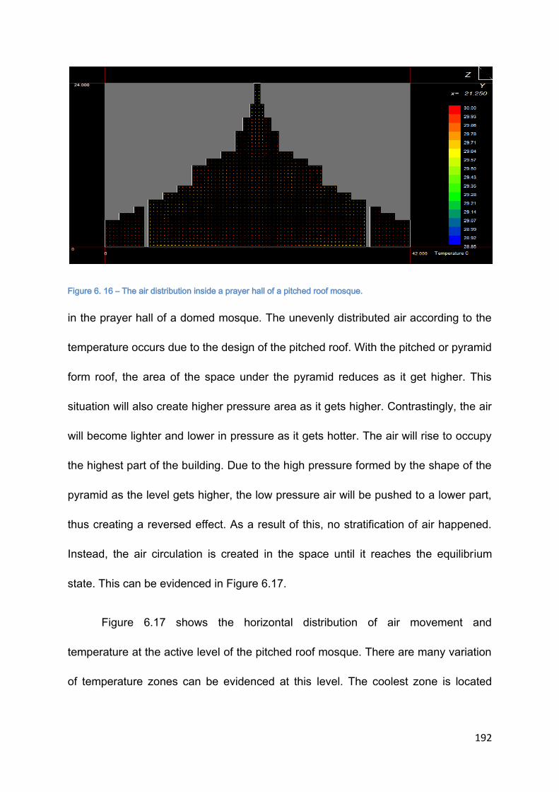
192
Figure 6. 16 – The air distribution inside a prayer hall of a pitched roof mosque.
in the prayer hall of a domed mosque. The unevenly distributed air according to the
temperature occurs due to the design of the pitched roof. With the pitched or pyramid
form roof, the area of the space under the pyramid reduces as it get higher. This
situation will also create higher pressure area as it gets higher. Contrastingly, the air
will become lighter and lower in pressure as it gets hotter. The air will rise to occupy
the highest part of the building. Due to the high pressure formed by the shape of the
pyramid as the level gets higher, the low pressure air will be pushed to a lower part,
thus creating a reversed effect. As a result of this, no stratification of air happened.
Instead, the air circulation is created in the space until it reaches the equilibrium
state. This can be evidenced in Figure 6.17.
Figure 6.17 shows the horizontal distribution of air movement and
temperature at the active level of the pitched roof mosque. There are many variation
of temperature zones can be evidenced at this level. The coolest zone is located
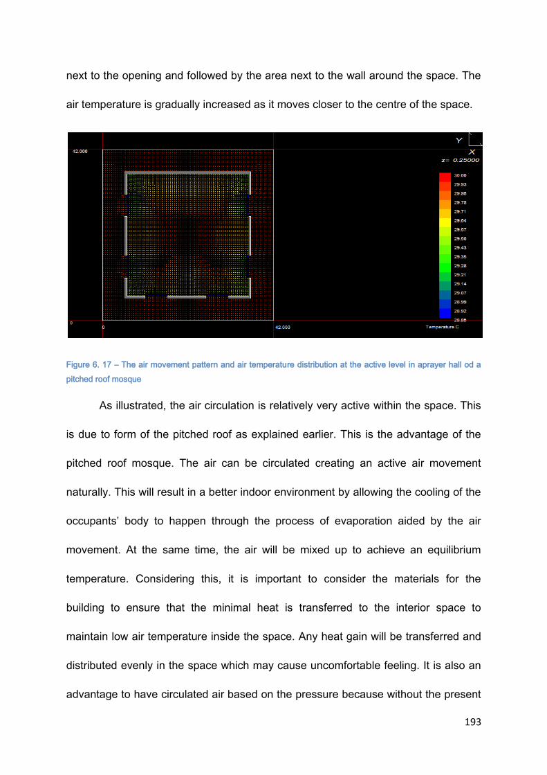
193
next to the opening and followed by the area next to the wall around the space. The
air temperature is gradually increased as it moves closer to the centre of the space.
Figure 6. 17 – The air movement pattern and air temperature distribution at the active level in aprayer hall od a
pitched roof mosque
As illustrated, the air circulation is relatively very active within the space. This
is due to form of the pitched roof as explained earlier. This is the advantage of the
pitched roof mosque. The air can be circulated creating an active air movement
naturally. This will result in a better indoor environment by allowing the cooling of the
occupants’ body to happen through the process of evaporation aided by the air
movement. At the same time, the air will be mixed up to achieve an equilibrium
temperature. Considering this, it is important to consider the materials for the
building to ensure that the minimal heat is transferred to the interior space to
maintain low air temperature inside the space. Any heat gain will be transferred and
distributed evenly in the space which may cause uncomfortable feeling. It is also an
advantage to have circulated air based on the pressure because without the present

194
of air movement from the outside, the air still has the ability to circulate and therefore
the process of cooling the building can occur regardless of the wind condition.
6. 3 CONCLUSION
A simulation using HTB2 and WinAir4 has revealed that each of the domed
and pitched roof design acts differently in influencing the thermal condition inside the
prayer hall. Firstly, based on the conducted simulation, it is found that the average
air temperature produced inside the prayer hall is relatively the same between both
models. However, the simulation has also revealed that the duration of heating and
cooling time between both models differs significantly where the pitched roof heats
and cools faster compared to the domed roof. Secondly, it has also been found that
when the roof space is separated from the prayer hall space, it will produce higher
air temperature compared to the prayer hall space. The difference between the two
spaces, however, is higher in the pitched roof compared to the domed roof mosque.
The MRT of the roof spaces are also significantly higher for both of the roofs
indicating that the roof is the main building element that is transferring the heat to the
inside compared to other building elements such as walls and floor. In addition,
changing the pitch level has insignificant changes to the air temperature for the
pitched roof. Thirdly, it has also been discovered that the pattern of air movement
and temperature distribution resulted from the roof design has a major difference
between the pitched and domed roof mosque. The simulation using WinAir4 reveals
that a domed roof mosque produces a clear stable stratification of air temperature
with the coolest air temperature located at the bottom layer and the hottest located at

195
the top level. A pitched roof mosque, on the other hands, produces no stratification
of air temperature due to the pyramidal form of the roof. Instead, the air temperature
is distributed in the space to achieve an equilibrium state. As a result of that, there is
an active air circulation happens in the pitched roof mosque. The domed roof
mosque shows a very stratified layer of air according to the temperature and leaving
the air to be static and calm. The ability to stratify the air temperature allows the
active level of the prayer hall to have the lowest temperature. As the building is
naturally ventilated, there is a possibility that the lowest temperature may not be
considered thermally comfortable. The heat transferred from the outdoor to the
indoor has to be seriously considered if this type of the roof is to be used. In addition
to this, the relative humidity is at the highest because the air temperature is the
lowest at the active level. Due to the constant condition of the air paired with the high
humidity level resulted from the stratification, this condition may create the feel of
stuffiness. Air circulation is needed to assist the transfer of the sweat from the body
to the air. Without enough air circulation, the process cannot take place efficiently.
The pitched roof mosque, on the hand, is not able to create stratification due to the
different pressures created from the shape of the roof. Instead of stratified air
temperature, the indoor air is circulated to reach the equilibrium state. The
temperature of the indoor air in this case is distributed evenly in the space and
depending on the materials selected for the building elements the air temperature
can be controlled. One of the benefits of using this type of roof is the air circulation
created by the roof. With the geometry, the air circulation is activated due to the
196
balancing act of the pressure and temperature influences on the air density. This
allows the building to cool faster and helps the process of evaporation.
Based on the findings, it can be concluded that the pitched roof mosque will
perform better in a naturally ventilated building located in the hot and humid climate
countries such as Malaysia. .

197
Chapter 7 – Discussion and Proposal
7.1 INTRODUCTION
Chapter 7 discusses the result and analysis obtained from Chapters 5 and 6.
Chapter 5 discusses the results and analysis based on the conducted survey and
Chapter 6 explains the results and analysis based on the conducted simulation using
HTB2 and WinAir4 software. Chapter 7 starts with the summary of the findings from
both investigations. It follows with the discussion on the comfort culture of the local
people and proposes the criteria that need to be considered in the thermal comfort
evaluation. The chapter continues on the suggestion of the best roof design to be
applied for Malaysia mosques in relation to the climate and comfort culture. It also
discusses the design guidelines that can be considered in designing a naturally
ventilated mosque based on the linkages obtained from the discussion on the
thermal comfort perception and results from the simulation. Finally, the chapter
concludes with the summary of the findings and suggestions.
7.2 THERMAL COMFORT CONDITION IN A TYPICAL MALAYSIAN MOSQUE
Four mosques representing the typical Malaysian mosques have been
selected for the investigation of the thermal comfort level inside the prayer halls. Two
of the mosques are pitched roof and the other two mosques are domed roof
mosques. The results in Chapter 5 have shown that the thermal comfort level varies
from one mosque to the others and it is not directly related to the roof designs. The

198
percentage of the participants who consider the thermal comfort condition as
acceptable cannot be reflected by the types of the roof design alone.
Table 7.1 shows the percentage of the votes received for the four selected
mosques. As described in Chapter 4 earlier, Mosque 1( Al Azim Mosque) and
Mosque 2(Jamek Mosque) are the pitched roof mosques. Both of them share
similarities in design, however they differ in term of size. Similarly, Mosque 3
(Sikamat Mosque) and Mosque 4 (Al Mizan Mosque) have a domed roof but they
differ in term of size and facade design. Mosque 4 is smaller than Mosque 3 and has
an open facade design. In term of size, Mosque 1 is the largest, followed by Mosque
3, Mosque 2 and Mosque 1.
TIME PITCHED DOMED
Mosque 1
(9,700 capacity
Mosque 2
(2,000 capacity)
Mosque 3
(3,500 capacity)
Mosque 4
(250 capacity)
Acceptable Unacceptable Acceptable Unacceptable Acceptable Unacceptable Acceptable Unacceptable
Noon 49% 51% 100% 0% 77% 23% 69% 31%
Afternoon 37% 63% 100% 0% 68% 32% 16% 84%
Evening 39% 61% 69% 31% 46% 54% 89% 11%
Average(%) 42 58 90 10 64 36 58 42
Table 7. 1 - Percentage of votes for the acceptable and unacceptable thermal comfort
condition in pitched roof and domed roof mosques.
Based on the ASHRAE standard that requires 80% of the votes to be acceptable for
a space to be considered thermally comfortable, only one mosque (Mosque 2) meets

199
the standard. Mosque 2 has the best thermal comfort condition followed by Mosque
3, Mosque 4 and Mosque 1. In terms of the thermal comfort condition in relation to
the periods of time, all mosques, except Mosque 2, fail to provide acceptable thermal
comfort condition during the noon and afternoon time which is the daytime period.
Besides the good thermal comfort perception received by the Mosque 2 during
daytime, it fails to provide the same condition during the evening time. Instead,
Mosque 4 provides thermally comfortable environment (89% vote) during the
evening time. The application of the pitched roof in Mosque 2 may have contributed
to the thermally comfortable environment provided during the daytime however the
pitched roof itself cannot be considered as a better roof design since Mosque 1
which is also a pitched roof mosque does not produce the same thermally
comfortable environment as Mosque 2. In fact, Mosque 1 which is also the largest
mosque among the four mosques is the least thermally comfortable mosque.
Mosque 3, which is the second largest mosque and applies domed roof has better
thermal comfort according to the votes received.
Another observation that can be made based on the collected data is that the
effectiveness of the pitched and domed roof design may also be associated with the
size of the prayer hall of the mosque. Based on the survey, Mosque 2 which is the
pitched roof mosque and the third largest or medium size mosque is considered the
best followed by Mosque 3 which is a domed roof mosque and the second largest
(district mosque). Mosque 4 which is a dome mosque is the third best and has the
smallest size or community size mosque and finally Mosque 1 which is the pitched

200
roof mosque and also the largest (state mosque) is the worst in terms of
respondents’ perception on the thermal comfort. From this arrangement it can be
interpreted that a pitched roof mosque may function well for a medium or smaller
size mosque since the larger pitched roof mosque (Mosque 1) does not provide a
good thermally indoor condition. On the other hand, it can also be suggested that a
domed roof mosque may work well with a bigger size mosque since the second
largest mosque (Mosque 2) that applies domed roof design is capable of providing
better thermally indoor environment compared to Mosque 1 and Mosque 4.
The size of the buildings affects many factors pertaining to the indoor thermal
condition. One of the factors is the exposure of the building elements to the sun. A
bigger size building may have increased areas of building elements such as building
facades and roof exposed to the sun which may affect the thermal condition. The
size of a building may also affect the natural ventilation especially cross ventilation.
For the case of a mosque, the basic geometry for the prayer hall is square in plan.
With this configuration, the width and the length of space is definitely affected as the
size increases. Therefore, the distance between the inlet and outlet opening is
proportionately increased as the size of the prayer hall increases. Slim buildings are
usually has better cross ventilation due to the closer distance between the inlet and
the outlet point.
It is also noticed that the evening period has the least acceptable votes
despite the fact that the air temperature during this time is the lowest except for
Mosque 4. The major difference between Mosque 4 and other mosques is that the

201
facade of Mosque 4 is open to the outside whereas other mosques have internal
walls that separate the indoor space with the outside. With this condition, the huge
openings allow the air exchanges to occur effectively and therefore, improve the
indoor thermal condition of the prayer hall. This situation may have affected the
thermal comfort condition of the indoor space during the evening time since the
outdoor air temperature during this time is lower. With a greater ability to exchange
the indoor air with the cooler outdoor air, it can certainly improve the thermal
condition during evening time. With these varied results received by the pitched and
domed roof mosques, it can be assumed that the roof design alone have insignificant
effect to the thermal comfort condition inside the mosque. The thermal comfort level
of each mosque is unique and cannot be determined only by the design of the roof,
in this case, the pitched and domed roof.
Being the surface that is exposed directly to the sun for the longest time, it is
predicted that the roof would affect the thermal comfort condition by increasing the
air temperature of the indoor space. This prediction may be true if the building is an
enclosed building and not a free running or naturally ventilated building. As a free
running or naturally ventilated building, the indoor thermal condition is heavily
dependent on the outdoor climatic condition. Normally, the heat transferred to the
internal space is originated from the building elements that are directly exposed to
the sun. However, the results have shown that this is not the case for the naturally
ventilated building that is heavily dependent on the outdoor thermal condition. It
seems that the heat generated from the roof has been balanced through the air

202
exchanges between the outside and inside. The indoor air temperature for the
selected mosques is found to be influenced by the outdoor temperature which is
varies from one mosque to the other. The simulation of the modelled buildings has
also shown that the influence of the outdoor air temperature to the indoor
temperature for both of the pitched and domed roof is almost the same when enough
openings created to allow effective air exchanges between the indoor and outdoor.
Figure 7. 1 - Comparison between the performance of the pitched and domed roof on space
air temperature
Figure 7.1 and 7.2 show the comparison of the mosque performance based on the
space air temperature and mean radiant temperature. Both of the figures show that
both of the roof designs are actually producing almost similar pattern of heat gain
and loss of almost the same value with a small differentiation of about 1 degree
Celsius. Earlier research (Auliciems &deDear, 1978; Brager and deDear, 1998;
deDear and Auliciems, 1993; Humphreys, 1978; Nicol, 2004) agrees that the indoor
air temperature is directly affected by the outdoor air temperature and other factors
202122232425262728293031323334353637383940
0.0
0
2.0
0
4.0
0
6.0
0
8.0
0
10
.00
12
.00
14
.00
16
.00
18
.00
20
.00
22
.00
0.0
0
2.0
0
4.0
0
6.0
0
8.0
0
10
.00
12
.00
14
.00
16
.00
18
.00
20
.00
22
.00
0.0
0Tem
pe
ratu
re(c
els
ius)
Time
HTB2 Simulation: Comparison ofTypical Domed and Pitched Roof Mosque Performance - Space Air Temperature
Space Air Temperature-Dome Space Air Temperature-Pitch
Outside Temperature

203
Figure 7. 2- Comparison between the performance of the pitched and domed roof on mean
radiant temperature
such as mean radiant temperature are less influential in affecting the thermal comfort
condition. Factors that are directly related to the condition of air such as relative
humidity and air movement may have stronger influential role in affecting thermal
comfort since in naturally ventilated building, the most influential factor is the outdoor
air condition and both of these factors are directly influenced by the outdoor
condition.
Based on these findings, it can be summarized that, the thermal comfort
condition in naturally ventilated Malaysian mosques cannot be determined based on
the roof design only. The effectiveness of the roof design in affecting the thermal
comfort condition is also related to the size and the openings provided by the
facades of the buildings. These design related factors may also be associated with
202122232425262728293031323334353637383940
0.0
0
2.0
0
4.0
0
6.0
0
8.0
0
10
.00
12
.00
14
.00
16
.00
18
.00
20
.00
22
.00
0.0
0
2.0
0
4.0
0
6.0
0
8.0
0
10
.00
12
.00
14
.00
16
.00
18
.00
20
.00
22
.00
0.0
0
Tem
pe
ratu
re(c
els
ius)
Time
HTB2 Simulation: Comparison ofTypical Domed and Pitched Roof Mosque Performance - Mean Radiant Temperature
Mean Radiant Temperature-Dome Mean Radiant Temperature-Pitch
Outside Temperature

204
the physical factors affecting thermal comfort such as air temperature, air movement
and relative humidity. The following section discusses the relationships of the factors
to one another in influencing thermal comfort in naturally ventilated Malaysian
mosques.
7.3 FACTORS AFFECTING THERMAL COMFORT LEVEL
As been discussed earlier, the condition of the outside air especially the
temperature strongly affects the indoor thermal comfort condition in a naturally
ventilated building. Other thermal comfort factors that are directly related to the air
condition are the air movement and relative humidity. In the study, these factors
have been found to be a ‘supporting’ contributor rather than a ‘joint’ contributor to the
thermal comfort condition. The ‘supporting’ contributor is defined as a factor that only
affects thermal comfort condition when the main factor, which is, in this case, air
temperature, is no longer under the ‘natural’ condition. The ‘joint’ contributor, on the
other hand, is defined as a factor that contributes to the thermal comfort in all
Mosque Comfortably warm Comfortable Suggested Temperature
Air Temp(0C) RH (%) Air Temp(0C) RH (%) Neutral (0) (1) 1. Al Azim 29.6 70.9 29.4 67.6 23.9 30.3 2. Jamek 28.4 82.1 28.2 77.5 25.0 31.0 3. Sikamat 28.3 76.3 30.7 67.1 27.1 30.9 4. Al Mizan 28.4 73.9 27.6 83.7 26.4 30.0
Table 7. 2 - The average air temperature and relative humidity based on the votes and the predicted neutral
temperature using the regression method.
condition. This is elaborated in the following session. Table 7.2 summarizes the
findings on the average air temperature and relative humidity under ‘comfortably
205
warm’ and ‘comfortable’ condition and the predicted neutral temperature using the
regression method based on the votes received.
7.3.1 Space Air Temperature and Thermal Comfort
There is no doubt that air temperature is an important factor in influencing
thermal comfort level. For a tropical climate country such as Malaysia, a typical daily
air temperature is ranging from 25 degree Celsius (early am hour) to 36 degree
Celsius with more than 70% of relative humidity. For those who have not
experienced this condition, they may consider the situation as intolerable and
thermally uncomfortable. However, the local people who have lived with the
condition throughout their lives may have different perceptions. Based on the
findings in Chapter 5, the research has revealed that the air temperature alone may
not be significant enough to influence the thermal comfort level. According to the
ASHRAE and Bedford scale, the ‘comfortably warm’ sensation vote under the
Bedford scale and ‘warm’ under ASHRAE scale is considered as the highest
tolerable limit for acceptable thermal comfort condition. Referring to Table 7.2, the
range of the air temperature for the ‘comfortably warm’ condition is from 28.3 0
Celsius to 29.6 0 Celsius. It is also noticed that the range of the ’comfortable’
condition collected from the field survey is from 28.2 0 Celsius to 30.7 0 Celsius. If
compared between the two ranges, the ‘comfortable’ condition has bigger range than
‘comfortably warm’ condition and the most upper range for the ‘comfortable’
condition even exceeds the most upper range of the ‘comfortably warm’ condition.
Compared to the comfort temperature suggested by the Fanger’s Thermal comfort
206
equation which is 25.60 Celsius, it is obvious that the respondents from this survey
have higher tolerance toward the air temperature. The wider range of temperature
that has been established for the ‘comfortable’ category also shows that the increase
in the air temperature, under certain circumstances, does not necessarily and
directly change the thermal comfort perception. The presence of other variables that
is related to the air condition such as the relative humidity and air movement has to
be considered in predicting the thermal comfort perception.
7.3.2 Humidity and Thermal Comfort
The high percentage of relative humidity has been considered problematic in
providing thermally comfortable environment especially when the average daily air
temperature is always higher than the suggested comfort temperature. The ideal
relative humidity is between 50% and 60%. Relative humidity that is more than that
becomes undesirable because it affects the thermal comfort level. The research,
however has found that the effect of higher content of humidity in the air (higher
percentage of relative humidity) is only felt when the air temperature experienced is
an excess. When the air temperature is at the comfort level, the higher content of
humidity in the air plays insignificant role in influencing the thermal comfort
sensation. However, the research has also shown that the tolerable air temperature
(when the air temperature is under ‘warm’ category) can become thermally
uncomfortable situation with the present of high humidity in the air especially when
there is no air movement. For a country with high air temperatures almost at all time,
the humidity has a significant role in influencing the thermal comfort level.
207
7.3.3. Wind Condition and Thermal Sensation
The wind condition has been found to affect the thermal comfort condition
considerably especially in a tropical country. Depending on the climatic zones, the air
movement or also known as draught can be a nuisance especially for the moderate
climate countries. For a tropical country that has hot and humid climate such as
Malaysia, the air movement is desirable at all time. It helps to cool down the body
and improve the perception of thermal comfort with the presence of air movement.
The findings in Chapter 5 shows that the air movement is preferred at all time
regardless of the other conditions of the variables which are the humidity and air
temperature. It provides the extra cooling sensation even though the thermal
condition is sensed to be neutral and comfortable. In addition to this the air
movement helps the cooling process by transferring the moisture from the body to
the air. The same situation has also been recorded in which the condition is felt to be
cooler with the present of air movement even though the air temperature has actually
been increased (Wigo & Knez, 2005).
With these findings, the level of importance for each thermal comfort variables
for the hot and humid countries, specifically Malaysia can be explained as shown in
the next figure (Figure 7.3). Referring to Figure 7.3, air temperature is the major
influence in thermal comfort for all climatic zones. The variance that can be found
between other climatic zones regarding the influence of air temperature is the ability
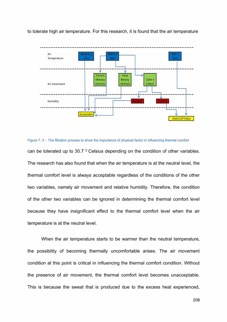
208
to tolerate high air temperature. For this research, it is found that the air temperature
Figure 7. 3 - The filtration process to show the importance of physical factor in influencing thermal comfort
can be tolerated up to 30.7 0 Celsius depending on the condition of other variables.
The research has also found that when the air temperature is at the neutral level, the
thermal comfort level is always acceptable regardless of the conditions of the other
two variables, namely air movement and relative humidity. Therefore, the condition
of the other two variables can be ignored in determining the thermal comfort level
because they have insignificant effect to the thermal comfort level when the air
temperature is at the neutral level.
When the air temperature starts to be warmer than the neutral temperature,
the possibility of becoming thermally uncomfortable arises. The air movement
condition at this point is critical in influencing the thermal comfort condition. Without
the presence of air movement, the thermal comfort level becomes unacceptable.
This is because the sweat that is produced due to the excess heat experienced,
Air
Temperature
Neutral ≤
25.6
Warm ≤
30.0
Hot >
30.0
Air movement
2.0 m/s
<Breezy
<4.0 m/s
Very
Breezy
>4.0 m/s
Calm <
2.0m/s
Humidity Neutral Humid
Acceptable
UNACCEPTABLE

209
keeps the heat of the body at the same level when here is no evaporative cooling
process occurred. This process, however, can happen naturally when the humidity
level is at the neutral level. However, with the high humidity level that is already exist
in the air of hot and humid countries the process could not be possible. The
assistance of the air movement is required to help the process to happen. The air
movement must be strong enough to be felt by the user. Slower air velocity which
cannot be felt by the skin of human body has insignificant effect in cooling down the
body. When there is little air movement present, the role of the humidity in
influencing the thermal comfort level becomes more significant. The combination of
‘warm’ thermal sensation, ‘calm’ air movement and ‘neutral’ level of humidity is still
tolerable due to the ability of the sweat produced to evaporate naturally. The
condition changes to become unacceptable when the air is humid which prevents the
process of evaporation to happen naturally. Regardless of the condition of the
humidity and wind condition, when the air temperature is considered ‘hot’, the
thermal comfort level becomes unacceptable.
Based on these observations, it is obvious that the air temperature is the
primary element in determining the thermal comfort level. At the correct and
appropriate air temperatures, the influences of other variables are not significant in
influencing the thermal comfort level as pictured in the figure. Therefore, it can be
concluded that the relative humidity and air movement are classified as ‘contributing’
factors rather than ‘joint factors’ due to their insignificances in influencing thermal
comfort condition. It is therefore recommended that the optimum air temperature

210
which can ignore the influences form the other two contributing factors to be
established so that it can be used as a reference in designing building or evaluating
thermal comfort.
7.4 THERMAL COMFORT RANGE AND INDEXES
The issue of the applicability of the evaluative scale such as ASHRAE in
evaluating thermal comfort especially in naturally ventilated building has been
discussed frequently by other researchers. Most of the research conducted on
naturally ventilated buildings in tropical countries found that the thermal comfort
predicted using the scale is not accurate. The analysis of the study also reveals that
the acceptable range of thermal comfort condition which is based on the ASHRAE
seven thermal sensation scale (between -1(cool) and +1(warm)) may not be suitable
to be used for naturally ventilated buildings in the hot and humid countries such as
Malaysia. The ‘cool’ condition is rarely achievable and the ‘warm’ condition is
perceived as an additional heat which only causes thermally uncomfortable
environment.
Referring to the Table 7.2, the importance of air temperature in influencing the
thermal comfort level can be evidenced. For examples, the average of the air
temperature for the ‘comfortably warm’ situation is ranged from 28.30 Celsius to 29.60
Celsius. Similarly, the predicted ‘warm’ temperature based on the ASHRAE scale
range from 30.00 Celsius to 31.00 Celsius. Both of these values show a minimal
variation when compared to the range of the ‘comfortable’ condition and ‘neutral’
211
temperature. The small range indicates that the air temperature can only be
tolerated until it reaches a specific temperature, in this case, 310 Celsius. If we look
at the filtration process of the thermal comfort factor (Figure 7.3), the influence of
other variables become effective when the air temperature is under ‘warm’ category
in which excessive heat energy is sensed by the body. This indicates that the ‘warm’
category cannot be used as a benchmark for the tolerable estimated air temperature
as other variables may contribute to the thermally uncomfortable environment. The
small range of air temperature recorded for this category also indicates that the air
temperature at this level can easily be affected by the other variables, in this case air
movement and relative humidity. Comparatively, when the air temperature is at
neutral level, the influences of other variables are insignificant and can be ignored.
Therefore in designing a building the targeted air temperature should be
benchmarked at the neutral category for this climatic region. Based on these
situations, it is suggested that the limit of acceptable thermal comfort condition
should be placed at 0(neutral) using the ASHRAE scale.
The perception towards the description on the thermal sensation scales may
also be viewed differently. A perception is usually influenced by the experience and
therefore it is unique to an individual. For a country with a moderate climate the
presence of a little heat may be desired. On the other hand, for a country with a hot
and humid condition the warm condition experienced in a moderate country may
have been considered as neutral by the people due to the acclimatization process.
Instead, the warm condition in hot and humid countries may have been considered

212
as very hot to the people in a moderate country. This depends on their experiences.
In a country with a hot and humid condition throughout the year, additional heat is an
excessive and not desirable at all time due to the existing high air temperature during
the day throughout the year. Based on this opinion and the discussion earlier it is
therefore inaccurate to apply the range of scale that is considered tolerable as
suggested by the ASHRAE scale to the hot and humid country such as Malaysia.
The ASHRAE has also suggested that in most indoor condition the comfort
temperature is around 25.6 0 Celsius. Using the neutral category under the ASHRAE
thermal sensation scale, the predicted neutral air temperature which is produced
from the linear regression based on the respondent votes is ranged from 23.9 0
Celsius to 27.10 Celsius for the four mosques selected. Based on these figures, the
average air temperature is 25.6 0 Celsius with the standard deviation of 1.43. It is an
agreement with the value that is proposed by the ASHRAE. Therefore, it is valid to
use this value which is 25.60 Celsius as the indoor comfort air temperature to be
achieved when designing a building. It is expected that when the air temperature is
within the range, the influences from other variables such as the humidity and the air
movement are minimal and therefore, thermal comfort condition can be achieved
regardless of the condition of other variables.
The ASHRAE thermal sensation scale also suggests that the range of the
thermally acceptable comfort condition is ranged from -1 or ‘cool’ to +1 or ‘warm’. It
has been argued by Charles (2003) that the thermal sensation scale is based on the

213
thermal sensation and cannot be used to measure the thermal comfort since thermal
comfort are influenced by many other factors and not just by thermal sensation. It
cannot be argued that other variables affected the thermal comfort perception
however the significance of each variables varies according to the local climate and
culture. For examples, in a moderate climate, the air movement often brings
discomfort as the air is normally cool. For a hot and humid country, the air movement
is desirable to help to cool down the body as the air temperature and humidity is
always high throughout the day. Based on this condition, the research has studied
the three important physical variables, namely, air temperature, relative humidity
and air temperature that can affect the thermal comfort level for the hot and humid
country, specifically Malaysia. As illustrated in the Figure 7.3, the air temperature is
the primary variable of thermal comfort level. However, only at certain temperature,
the presence of other variables can be ignored as the effect is insignificance.
Therefore, for the hot and humid country, it is inappropriate to use the thermal
sensation scale to predict the thermal comfort condition of a building since other
factors may have affected the thermal comfort level as the temperature changes.
The research also suggests that the incorporation of the humidity and air
movement into the evaluative thermal sensation scale may produce better evaluative
result. The suggestion for the proposed thermal comfort sensation scale is
illustrated in the next figure (Figure 7.4).

214
Thermal Sensation (TS)(ASHRAE)
Too Cold (-3)
Cold (-2)
Cool (-1)
Neutral (0)
Warm (+1)
Hot (+2)
Too Hot (+3)
Air Movement(VA) Very Breezy (0) Breezy (1) Calm(2)
Humidity (H) Neutral (0) Humid (1) Very Humid (2)
Figure 7. 4 – Proposed Thermal Comfort Perception scale for naturally ventilated building in hot and humid
climate
In evaluating the thermal comfort condition of a space in a hot and humid
area, three variables are included to get an improved result which does not only
consider the thermal sensation but also the humidity and air movement. For the
thermal sensation scale, the ASHRAE seven thermal sensation scale is applied as it
has been accepted throughout the world. Into this existing scale, the air movement
scale is added which is divided into three simple categories which are calm(2),
breezy (1) and very breezy (0). The same scale has also been given to the humidity
which is neutral (0), humid (1) and very humid (2). To determine the thermal comfort
level, the score from the three scales are added and divided by three to get an
average. If the answer falls between -1 and +1, the space can be considered as
thermally comfortable and acceptable. In other words, it can be written as:
Thermal Comfort = (Thermal sensation(TS) + Air Movement (VA) + Humidity (H))/3
This addition is to improve the evaluation on thermal comfort as the evaluation
tool also considers the humidity and air movement. With this combination, the
evaluation is not just on thermal sensation but also consider other important
variables in evaluating thermal comfort especially for the region with hot and humid
climate like Malaysia. The issue has been discussed quite widely especially on the
application of the scale on the naturally ventilated building especially in a tropical

215
country and with the introduction of the combination, it can help to produce better
prediction on the thermal comfort condition for the region that the thermal comfort is
highly affected by the relative humidity and air movement.
7.5 DESIGN GUIDELINES PROPOSAL
Thermal comfort can be achieved if the design of a building considers and
responds well to the factors affecting the thermal comfort especially the physical
factors. These factors are air temperature, relative humidity and air movement. As
discussed earlier in this chapter, the air temperature is the primary factor affecting
the thermal comfort of the indoor space followed by the air movement and finally
relative humidity. For a naturally ventilated building, the indoor air temperature is
heavily dependent on the outdoor air temperature. Similarly, the relative humidity of
the indoor is also influenced by the outdoor climatic conditions. Both of these factors,
the air temperature and relative humidity, are inversely correlated. Theoretically,
when the air temperature increases, the relative humidity reduces as the hotter air
has the ability to contain more moisture compared to the cooler air. Therefore, the
change in the air temperature also affects the relative humidity. Due to this, by
controlling the rate of air exchanges from the outside to the inside, both of the air
temperature and relative humidity can be controlled. In addition to this, the
movement of air, in many ways, helps in improving the thermal comfort perception. It
has been shown that the air temperature is favoured at all time regardless of the
condition of air temperature. These issues have to be considered in designing a
building in order to provide a thermally comfortable indoor environment.

216
The two most popular designs of the mosque in Malaysia is the domed
mosque and pitched roof mosque. The domed mosque design has become more
popular recently compared to the pitched roof mosque. Arguments about its
insensitivity to the cultural and traditional sensitivity are still being discussed. Little is
also known about the suitability of these designs in responding to the climatic factors
in providing thermal comfort indoor environment. Based on the simulation using
HTB2 and WinAir4, a different effect has been revealed resulting from the use of the
two types of the roof. Based on the findings which have been discussed in Chapter
6, guidelines are proposed to help the designers in designing a mosque that can
provide thermally comfortable indoor environment with minimal assistance of
mechanical equipment.
As the air temperature is the primary element that determines the thermal
comfort, a closer attention should be given on how to maintain a low air temperature
inside the space. For a naturally ventilated building, controlling the air temperature
that goes into the building is not possible. Changing the air temperature is only
possible with the help of an air conditioning system. However, maintaining the indoor
temperature below the outdoor temperature can be done and this is one of the
measures suggested in order to keep the indoor space thermally comfortable.
Improving the natural ventilation is an important measure to tackle the problem of
thermal discomfort as found out earlier that the air movement is favourable in
maintaining the thermal comfort. There are many ways that can be applied to the
design to improve the thermal indoor condition. However, based on the findings
217
obtained from the research, concentration on these two objectives is thought to be
more significant in an attempt to design a naturally ventilated mosque that can
passively provide a thermally comfortable indoor condition. The objectives are:
a. Reducing the Mean Radiant Temperature (MRT)
Since the air temperature that goes in the building cannot be manipulated naturally,
controlling the MRT is the best way to improve the indoor thermal condition. MRT
can be described as the average temperature from the surfaces of the space that
can be felt by a person occupying the space. To maintain the thermal comfort level
of the space, it is suggested that the maximum differences between the air
temperature and the MRT is about 2 0 Celsius above the air temperature. This is only
true for a moderate country that experiences moderate temperature and require
additional heat. For a building that is located in a tropical region, a cooler surface is
preferred to absorb the heat energy from the air temperature. There are many ways
that have been suggested by the researchers that can be applied in designing the
mosque.
One of the ways is to provide shade to the surfaces making up the space, for this
case, the prayer hall. Malaysia is located close to the equator (2°30 N 112°30 E).
Due to this, the sun is located above the head at most of the time throughout the
daytime. The role of the roof in shading the surfaces especially the wall bordering the
prayer hall becomes critical as it reduces the heat conduction and radiation from the
walls to the prayer hall. It has been evidenced in recent mosque development that
the roof has been extended beyond the building line to provide shade to the walls of

218
the prayer hall. An additional space which is called a verandah or passageway has
also been introduced to create an intermediate space between the outside and the
prayer hall in an attempt to reduce the heat transmission from the outside. Even
though these measures have been implemented, a careful study to determine the
size of the overhang or extension is required in proposing the extension especially
when the position of sun is low which happens during the early morning and late
afternoon. It has been identified through the observation that the overhangs provided
especially in a large mosque are unable to provide shade to the walls during these
periods of time due to the bigger distance from the floor to the overhangs allowing
the direct sunlight to fall on the walls. In some cases, the prayer hall is located at an
elevated level and this exposes the building elements especially the walls to the
direct sunlight. The introduction of vegetation especially trees can be introduced to
filter the sunlight that reaches the wall and this measure is more effective if the
prayer hall is located at the ground level that allows the filtration of the sunlight by
the trees and vegetation to take place.
It has also been revealed in the research that the roof element creates higher MRT
in comparison with the other building elements. Obviously, the element is exposed
longer to the sunlight compared to other elements and this allows the materials to be
heated up and radiated the heat to the inside. Therefore, selecting the appropriate
materials to be used as the roof materials is important. It is suggested that the
materials suitable to be used for this climate are the materials that have low heat
conductivity and retention properties. This means that the materials are able to
219
reduce the heat transfer from the outside to the inside and able to cool down quickly.
The simulation conducted based on the common materials and construction method
used for both roofs indicates that the dome roof which is predominantly made of
concrete heats up slower and has lower MRT in comparison with the pitched roof
which is mainly constructed using clay tiles with ceiling and timber frames. In
reducing the heat transfer to the interior space, the concrete roof due to its low
conductivity properties is able to retain the heat in the structure. The thickness of the
construction allows the structure to keep some of the heat before releasing it to the
interior space. The materials that are used in the pitched roof construction have low
conductivity too. However, the thickness of the materials is unable to retain the heat
and therefore releasing most of the heat absorbed to the interior space. Due to this
reason too, the cooling process of the pitched roof is faster when compared to the
domed roof.
Both of these roofs have their advantages and disadvantages. The ability of the
domed roof to provide low MRT during the day is appreciated. However during the
evening time the MRT becomes higher when compared to the MRT provided by the
pitched roof during the evening time. It also creates a bigger difference between the
outdoor and indoor operative temperature which is not advisable. Based on the
survey conducted, it is also recorded that the evening is the period that many of the
occupants feel less comfortable even though the recorded air temperature is lower.
This situation explains why the thermal comfort condition is at worst during the
evening time.

220
The problem with pitched roof is the high MRT recorded during the afternoon time. It
has been suggested that one of the ways to reduce the radiation of heat from the
roof element is to provide appropriate insulation. Reflective insulation is one of the
methods suggested to reduce the transfer of the heat through radiation. Proper
installation of the reflective insulation is advised to ensure the effectiveness of the
materials.
b. Improving the natural ventilation
Air movement is one of the criteria that have been requested by the respondents in
the preference survey. Knowing that the importance of the air movement in providing
thermal comfort for this region especially for this building type, measures to improve
the air movement or ventilation for the building have to be considered as a main
priority in the design process. The simulation conducted on the domed roof and the
pitched roof mosque has revealed that each of the building acts differently in terms
of the air circulation inside the space.
The domed roof, besides the ability to store heat for a longer time, has the
ability to stratify the air according to the temperature. The hotter air is lighter and less
dense compared to the cooler air which is denser. Due to this the hotter air
accommodates the higher parts of the volume while the denser air occupies the
lower part of the space. The benefit of this ability is the lowest layer of air is always
the coolest air in the space. For a naturally ventilated building, it is quite common to
have the indoor and outdoor air temperature to be the same because of the
uncontrollable air temperature that enters the indoor space. Due to no differentiation
221
between the indoor and outdoor air temperature, the air is quite stagnant at this level
because there is not enough temperature difference to activate the movement. Since
the air movement is desirable at all times this condition is not so favourable. With the
stagnant air, the influence of relative humidity may be significant to the thermal
comfort condition. The condition is only acceptable when the air temperature is at or
below the suggested neutral temperature which is 25.6 degree Celsius. This
temperature only occurs when the building is not in use which is during the early
morning time or late night time.
The pitched roof, on the other hand, is able to circulate the air with different
temperature in the space. No stratification of air temperature occurs in the pitched
roof mosque. Instead, the air is moved around the space to achieve the equilibrium
state. The ability to move the air around the space is due to the variation of air
density as a result of the roof shape which has been discussed earlier in Chapter
Six. With this situation, an active movement of air can be seen inside the pitched roof
mosque. Due to the natural forces, the air movement cannot be sensed physically by
the body. However, with the air movement, it allows the distribution of the humidity
as well which in returns helps the evaporative process to take place.
Natural ventilation can happen effectively when there is a difference of
pressure between the inlet and outlet and in vertical temperature. Cross ventilation is
caused by the high pressure at the inlet point and the low pressure at the outlet
point. It is caused by the wind force that pushes the cooler air inside the space to
222
replace the hot air by pushing it out through the outlet. The effectiveness of the cross
ventilation is based on the positioning of the inlet and outlet which should be aligned.
Stack effect ventilation on the other hand, is caused by the difference in the density
of the air as a result of temperature change. In order for the stack effect to happen
the space must have lower and upper openings. The stack effect ventilation is more
effective if the distance between the lower and the upper opening is greater as the
pressure differences becomes greater due the temperature differences. The lighter
and hotter air will rise and be replaced by the cooler air at the lower level. Both of
these measures are the options that can be applied to both of the mosques. The
question is, which measure is more appropriate and effective to be applied to the
mosque?
As discussed earlier, the domed mosque has the ability to stratify the air
temperature which means that the coolest air will be located at the lowest level and
the hotter air will rise to the upper level. The active level of the mosque is between
the floor level up to 2 meter level. Due to this stratified air according to the
temperature, it is important to maintain the air temperature at the active level. The
effective way to maintain the air temperature at this level is through cross ventilation.
Cross ventilation is relied on the availability of the inlets and outlets. Therefore,
providing ample openings as inlets at one side and outlets at the opposite side may
help the cross ventilation. The openings should be high enough to allow the
exchanges of hot and cold air at this active level. Openings that are too high may not
be effective as the domed mosque may not be able to effectively stratify the air

223
according to the temperature. It is advisable to maintain the height of the opening to
the height of the active zone required only to ensure that the temperature at this level
is at the lowest possible temperature by exchanging it with the outdoor temperature.
Due to the ability to stratify the air according to the temperature, there is a
temperature difference between the lower and the upper part of the space. The
differences in air temperature according to the heights of the space also allow the
natural ventilation which is called stack effect ventilation to occur. Openings at the
lower and upper parts of the space have to be provided to allow the flow of the air.
Due to the temperature difference, the hotter air rises as it is lighter than the cooler
air. It leaves the lower part to be at the low pressure condition which allows cooler
air to enter the space. The hotter air will flow to the outside through the openings
made at the upper level. This happens when there is a pressure difference between
the inside and the outside. The outside pressure has to be lower to allow the hotter
indoor air temperature that has higher pressure to flow to the outside.
Unlike the domed roof, the pitched roof mosque allows the air to circulate in
the space to achieve the state of equilibrium due to the pyramid shape. With this
condition, instead of stratifying the air, the temperature of the air is at the average at
all times. To maintain the air temperature at the lowest possible, the exchanges of
the air between the indoor and the outdoor must be efficient. The cross ventilation
must efficiently takes place by providing the inlet and outlet across each other. As
suggested by other researchers, the inlet must be wider to allow as much air to enter
224
at the active level. The cross ventilation to allow the air exchanges is more critical for
the pitched roof mosque compared to the domed mosque. The air is mixed through
the air circulation to produce an average or equilibrium air temperature. Due to this
process the air inside the space will get hotter if there is no air exchange between
the outside and the inside. To ensure that the air temperature is maintained at the
lowest possible, the hotter air needs to be replaced by the cooler air. Therefore,
effective and ample openings to act as inlets and outlets for the air are necessary.
The continuous air movement resulted from the pyramid shape of the roof
helps to distribute the humidity in the space. The continuous movement of air may
not be felt by the bare skin however, it helps to distribute the humidity around the
space. As a result the relative humidity is almost the same at any level of the space.
The air movement can also help to cool down the body through the process of
evaporation of the sweat. Compared to the domed roof, the air is stratified. The
lowest layer of air is the coolest air. In many cases, in a naturally ventilated building
located in the hot and humid area, the air temperature is often higher than the
preferred temperature. When the air is at the coolest condition, the relative humidity
is normally at the highest. With this condition, and the high outside air temperature,
there is a possibility that thermally uncomfortable environment will occur which
mostly resulted from the high content of humidity and the stagnant of air due to the
stratification of the air.

225
The stack effect ventilation is another method to promote natural ventilation.
This application requires the air temperature difference between the lower and upper
part of the building. Since the ability of the pyramid to circulate the air due to the
reverse effect of pressure and density, it is less beneficial to employ the stack effect
ventilation for the pitched roof mosque.
With these findings, it is suggested that the selection of the roof designs
between the domed and pitched roof must also be associated with the size of the
mosque and the opening design. A bigger mosque is more suitable to apply domed
roof as the size will also provide a bigger difference in height of the building to allow
the stack effect ventilation to occur. The ability of the domed roof to stratify the air
improves the effectiveness of the stack effect ventilation. Cross ventilation is not
efficient for a bigger mosque due to the greater distance between the inlet and the
outlet of the air. A smaller mosque where cross ventilation can occur effectively, a
pitched roof is more relevant as its ability to circulate the air inside the space will
provide continuous air movement which is desirable for the hot and humid country
such as Malaysia. This will also influence the design of the opening to ensure that
the cross ventilation can happen effectively.
7.6 CONCLUSION
It has been found that the thermal comfort factors affecting the mosque users
are primarily influenced by the air temperature called the ‘primary factor’ and
assisted by ‘contributing factors’ which are the relative humidity and air movement.

226
The presence of air movement is desirable at all time but the relative humidity is only
effective in influencing the thermal comfort when the air temperature is beyond the
neutral temperature, especially when the air is stagnant. Due to this finding, it is
important for a naturally ventilated building to have efficient natural ventilation to
ensure that the level of thermal comfort inside the space is tolerable. The presence
of air movement, in many circumstances, is able to improve the thermal comfort
level.
The study on the influence of the two types of roof designs which are the
domed and pitched roof has revealed that both of the design will have the same
effect to the air temperature inside the prayer hall since both of the designs are
naturally ventilated and the indoor air temperature is heavily dependent on the
outdoor temperature. However, both of the designs have been found to be able to
influence the air distribution and movement inside the prayer hall in a different
manner. The major difference between the domed and pitched roof mosque is that
the domed mosque has the ability to stratify the air according to the temperature
layering the coolest air at the lowest level and the hottest air at the highest level. This
situation will create a stagnant air situation inside the space. The pitched roof, on the
other hand, is able to mix the cool and hot air to achieve the state of equilibrium
creating an active air movement inside the space naturally.
Based on the findings on the thermal comfort culture and the influences of the
two roof designs inside the prayer hall, it can be concluded that the pitched roof

227
design is more suitable to be applied for Malaysia which has hot and humid climate.
This is due to the reason that the pitched roof mosque has the ability to circulate the
air creating continuous air movement inside the space assisting the evaporative
process to happen which can cool down the body. Even though the air movement
may not be felt by the users, this continuous air movement will help to reduce the
feeling of stuffiness. The thermal comfort culture of the place also supports that the
air movement is highly desirable at all time regardless of the situation and with the
ability of the pitched roof to circulate the air without the assistance of the mechanical
equipment, it is highly recommended to use the pitched roof design for the mosque
in Malaysia.

228
CHAPTER 8 – CONCLUSION
8.1 INTRODUCTION
The intention of the research is to study the thermal comfort condition in
typical naturally ventilated Malaysian mosques which are significantly characterized
by the roof designs either domed or pitched roof. Along with this investigation, the
study also looks at important factors affecting the thermal comfort level for this type
of building and at the same time to reveal the best roof design to be applied in
Malaysian mosques that is able to produce better indoor thermal condition. The two
most popular roof designs applied at the mosques which are the domed and pitched
roof mosques have been questioned on their suitability and relevance to the local
culture and Islamic religion. Both designs have been seen to have their own
strengths in relating to the culture and religion and therefore it is difficult to justify
which roof design is better than the other. The information on how these two designs
responding to the local climate may help in determining which design is better to be
applied for this country and region. The design should not only respond well to the
culture and religion but most importantly to the climate. In searching for the
information which involves the thermal comfort culture of the local people, many
surprising findings have been unearthed. These findings, later on, lead to the
suggestions to improve the mosque designs. This chapter summarizes the findings,
and discusses the implication that they may have on future investigations.

229
8.2 RESEARCH PROCESS, AIMS AND OBJECTIVES
The aim of the research is to study the effectiveness of the two typical
mosque roof designs which are the domed and pitched roof design in providing
thermally comfortable indoor environment in a typical naturally ventilated mosque of
Malaysian. The investigation has been conducted using survey and field
measurement and simulation. Figure 8.1 shows the process involved in the
investigation.
Figure 8. 1 - The research process diagram
The objectives of the research using the survey and field measurement approach
are:

230
- The users perception on the thermal comfort condition of the two types of
the mosques which are the pitch and domed roof mosques.
- The dominating factor of thermal comfort level and other contributing factors
- The range of tolerable indoor air temperature for the prayer hall of the
selected mosques
- The appropriate methods of evaluating the thermal comfort condition for this
climate and region and specifically for this building type.
The objectives of the research using simulation based on the software HTB2 and
Win Air4 are:
- The heat gain and loss pattern
- The influence of the opening area and the heat gain
- The roof space vs. the prayer hall space
- Wind movement pattern and air temperature distribution
8.3 FINDINGS
Several findings have been discovered during the investigation. Table 8.1
shows the summary of the objectives for and findings obtained from the survey and
field measurement methods. Firstly, based on the analysis conducted on the data
collected through the survey and field measurement approach, it is found that there
is no direct relationship between thermal comfort with the roof design by itself. The

231
Survey and Field Measurement Method
Objectives Findings
• The users perception on the thermal comfort condition of the two types of the mosques which are the pitch and domed roof mosques.
• There is no direct relationship between thermal comfort with the roof design by itself.
• The dominating factor of thermal comfort level and other contributing factors
• The thermal comfort is significantly governed by the air temperature. When the air temperature is considered ‘neutral’, the other factors (ie: relative humidity, air movement) are ineffective in influencing thermal comfort.
• Air movement is always preferable in any condition.
• The range of tolerable indoor air temperature for the prayer hall of the selected mosques
• The range of the neutral temperature is between 23.9 Celsius and 27.1 Celsius .
• The appropriate methods of evaluating the thermal comfort condition for this climate and region and specifically for this building type.
• Based on ASHRAE Thermal sensation scale, the acceptable condition for thermal comfort is between scale ‘cool’ and ‘warm’(-1 and 1). However, for tropical climate zone which rarely experience ‘cool’ climate, the acceptable condition should be only under ‘neutral’ scale.
Table 8. 1 - The summary of the objectives and findings obtained from the survey and field measurement
methods.
roof design in some ways, affects the thermal comfort. However there is no direct
relationship between thermal comfort and the roof designs investigated which are the
pitched and domed roof designs. The thermal comfort prediction cannot be based on
232
the roof design itself. Instead, the total design including the facade and openings
must be considered in evaluating thermal comfort. However, there is a pattern that
shows a smaller mosque has better thermal comfort condition. Instead of the roof
design, the size together with the roof design acts as a factor in influencing the
thermal comfort condition.
Secondly, it is also discovered that the thermal comfort is significantly
governed by the air temperature. When the air temperature is considered ‘neutral’,
the other factors (ie: relative humidity, air movement) are ineffective in influencing
thermal comfort. The humidity would only have its influence when the air
temperature was beyond the tolerable limit with little air movement. Based on these
findings, it is suggested that the ‘neutral’(0) level using the ASHRAE scale for the
thermal sensation should be used as the optimum or desired condition omitting the
scale ‘warm’(+1) as an acceptable range suggested by the ASHRAE. At this level,
the condition of other variables could be ignored. Rather than to accommodate many
variables which may lead to some complication, concentrating on one major variable
at a time would be an effective way of tackling the problem. Based on this
suggestion, it was proposed that the optimum or desired air temperature is 25.6
degree Celsius. The range of the tolerable temperature suggested is between 23.9
Celsius and 27.1 Celsius. The suggested temperature was lower than what has
been suggested by other earlier researchers. Most of the research found that the
neutral temperature for naturally ventilated building was around 28 degree Celsius
which was fairly high when compared to the predicted neutral temperature from the
233
study. The reason that the air temperature proposed by this study was lower is most
probably due to the clothing restriction. In a mosque, the users are required to dress
appropriately according to the guidelines provided. The normal clothing for man has
to cover all the body part and only exposing the head, hand and feet. Some of the
users also wear headwear called ‘songkok’ when performing their prayers. The
restrictions on the way to dress unable the user to make changes to the way they
dress when staying inside the mosque. With this type of clothing it is estimated that
the clo. value is about 0.75 -0.80. Due to the restriction to respond adaptively, the
air temperature desired is lower than it has been estimated earlier by other research.
This is the desired indoor air temperature to be achieved for the space of prayer hall
in a mosque only.
Thirdly, it is also found that air movement is always preferable in any condition
If the desired air temperature as mentioned above is unattainable, the next corrective
measure is to provide or promote air movement in the space. It has to be sensible by
the human body and continuous to ensure that the thermal comfort level can be
maintained.
Table 8.2 summarizes the objectives for and findings from the simulation
method using the HTB2 and WinAir4 software developed by Cardiff University.
Based on the simulation utilizing the HTB2 and WinAir4 software, a number of
findings had been discovered. Based on the simulation using HTB2 (refer Table 8.2),
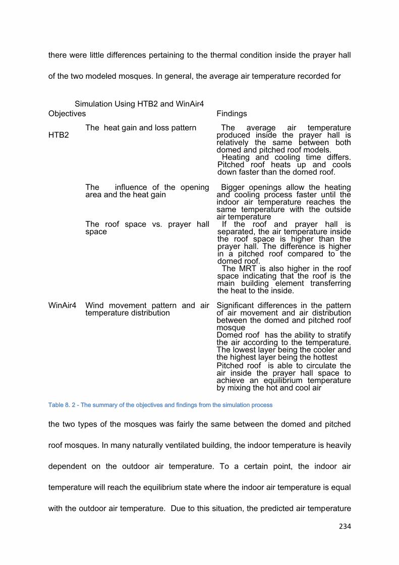
234
there were little differences pertaining to the thermal condition inside the prayer hall
of the two modeled mosques. In general, the average air temperature recorded for
Simulation Using HTB2 and WinAir4
Objectives Findings
HTB2
The heat gain and loss pattern The average air temperature produced inside the prayer hall is relatively the same between both domed and pitched roof models. Heating and cooling time differs. Pitched roof heats up and cools down faster than the domed roof.
The influence of the opening area and the heat gain
Bigger openings allow the heating and cooling process faster until the indoor air temperature reaches the same temperature with the outside air temperature
The roof space vs. prayer hall space
If the roof and prayer hall is separated, the air temperature inside the roof space is higher than the prayer hall. The difference is higher in a pitched roof compared to the domed roof. The MRT is also higher in the roof space indicating that the roof is the main building element transferring the heat to the inside.
WinAir4 Wind movement pattern and air temperature distribution
Significant differences in the pattern of air movement and air distribution between the domed and pitched roof mosque Domed roof has the ability to stratify the air according to the temperature. The lowest layer being the cooler and the highest layer being the hottest Pitched roof is able to circulate the air inside the prayer hall space to achieve an equilibrium temperature by mixing the hot and cool air
Table 8. 2 - The summary of the objectives and findings from the simulation process
the two types of the mosques was fairly the same between the domed and pitched
roof mosques. In many naturally ventilated building, the indoor temperature is heavily
dependent on the outdoor air temperature. To a certain point, the indoor air
temperature will reach the equilibrium state where the indoor air temperature is equal
with the outdoor air temperature. Due to this situation, the predicted air temperature

235
for the space was fairly the same for both types of designs. The significant difference
can only be seen on the duration taken by the space to cool down. The pitched roof
mosque heated up and cooled down faster than the domed roof mosques. The ability
to cool down faster has been suggested as one of the good characteristics of a
naturally ventilated building located in a hot and humid area. Based on this notion,
the pitched roof design was more appropriate to be applied for the area. Further
investigation using the HTB2 also showed that the roof space under the pitched roof
was hotter than the roof space under the dome roof while the prayer halls under
these two roofs had approximately the same air temperature. It also showed that the
roof space under the pitched roof cooled faster than the roof space under the domed
roof. In addition to this, the Mean Radiant Temperature predicted by using the HTB2
for the roof space when compared to the prayer hall was higher. This showed that
the roof contributed bigger heat energy to the interior space when compared to other
building elements such as the floors and walls. It is therefore suggested that careful
attention should be given to the selection of roof materials and construction to
reduce the radiant heat generated from the roof.
WinAir4 was applied to visualize the distribution of the air and the air
movement pattern inside the space. Surprisingly, the simulation produced a
distinctive variation in the distribution of the air inside the prayer hall of the domed
and pitched roof mosque. The domed roof mosque had the ability to stratify the air
according to the temperature whereas the pitched roof mosque averaged the air
temperature inside the space by creating continuous air circulation. This finding

236
produced information that helps in the understanding of the building behaviour and
therefore, measures can be advised to improve the design to produce a thermally
comfortable indoor environment.
Survey and Field Measurement
Simulation
• The thermal comfort level of each
mosque is unique and cannot be determined only by the design of the roof.
• Reducing the Mean Radiant
Temperature. Minimising the heat transfer from the building elements especially the roof being the most exposed building elements to the sun.
• The air temperature is the ‘primary’
factor affecting thermal comfort whereas the air movement and relative humidity are the ‘contributing’ factors.
• Improving the natural ventilation.
Air movement is always desirable at all time. Applying the correct measure in providing natural ventilation is crucial to ensure the effective natural ventilation to happen
• Air movement is always desirable at
any condition
• The evaluative method of inferring
thermal comfort may need to be changed due to the different perception of thermal experience. Neutral temperature should be used in determining the ideal or acceptable temperature. Scale of Relative Humidity and air movement need to be incorporated in the evaluative method.
Conclusion
• Pitched roof mosques are better than the domed roof mosques in
providing thermally comfortable indoor environment due to their ability to circulate the air to achieve a state of equilibrium creating continuous air movement provided that good cross ventilation is present. Smaller and medium scale mosque
• In domed mosques the air is stratified according to the temperature and therefore creating stagnant air condition. Stack effect ventilation is effective to be used. Large scale mosque.
Table 8. 3 - The outcomes from both methods and the conclusion
Chapter 7 discussed and provided synthesis between the findings from the
survey and the simulation. Table 8.3 shows the outcomes from both approaches
237
and the conclusion based on the outcomes. Based on the results, the better
selection of the roof design on the mosque can be determined and proposals to
improve the design are suggested. From the Survey and Field Measurement
findings, it is undisputable that the air temperature is the major factor in affecting the
thermal comfort. The research had revealed that the air movement was equally as
important as air temperature in affecting the thermal comfort in this type of climate.
The air movement is preferred in almost all condition of air temperature either neutral
or warm condition.
Another suggestion that is made resulted from the investigation is to improve
the evaluative scale by incorporating the scale of humidity and air movement
sensation into the ASHRAE Thermal Sensation Scale in predicting the thermal
comfort condition for a naturally ventilated building located in a tropical country that
has hot and humid climate. It has been argued that the ASHRAE Thermal Sensation
scale is not applicable in predicting the thermal comfort perception especially for a
naturally ventilated building in tropical countries. It is just referring to the thermal
sensation, whereas the thermal comfort is comprised of other variables. Despite the
fact that it is not relevant, the ASHRAE Thermal Sensation scale is still being
referred in predicting the thermal comfort condition. The incorporation of perception
on the level of humidity and wind condition adds the consideration of two more
factors that are highly influential in affecting the thermal comfort for a building located
in the hot and humid climate. With this incorporation the application of the revised
ASHRAE Thermal Sensation scale can be more relevant in evaluating the thermal

238
comfort condition for the tropical countries. Further testing on the scales must be
conducted before the scale can be used.
The analysis from the simulation is suggesting that minimizing the heat
transfer from the building elements especially the elements that are directly exposed
to the sun. With the location of the country that is closer to the equator, the position
of the sun is almost on top of the head during daytime exposing the roof directly to
the sun almost at all time during the day. Therefore it is necessary to reduce the heat
transfer from the roof of a building. In addition to this, it is also suggested that the
ventilation inside the mosque has to be effective either using cross ventilation or
stack effect ventilation. Both of the mosques show different behavior in distributing
the air inside the space and therefore correct approach in selecting the types of
natural ventilation is important in order to improve the thermal comfort level inside
the space.
Based on all the findings discovered during the research, it is finally
concluded that the pitched and the domed roof of a mosque acts differently
especially in air movement and temperature distribution inside the space it covers.
The domed roof mosque was more suitable to apply the ‘stack effect’ concept due to
its capability to stratify the air according to the temperature. This creates a difference
in temperature between the lower which is the inlet and the upper part which is the
outlet. With this ability, it is also suggested that the domed roof is more suited to a
bigger scale mosque. A mosque that has a larger built up area has a difficulty in

239
cross ventilation due to the larger distance between the inlet and outlet. Therefore,
the exchanges of the cooler air from the outside to the inside may not occur
efficiently. The larger built up area of the mosque is normally complimented with the
height. With the sufficient distance created between the lower inlet and the upper
outlet assisted with the ability to stratify the air according to the temperature, the
‘stack effect’ ventilation can happen effectively in the domed roof mosque. In addition
to this, the stratification of the air keeps the lower part of the prayer hall space which
is also the active level at the lowest temperature at all time. The design guideline
proposal should focus on improving the ‘stack effect’ ventilation rather than cross
ventilation.
In the case of the pitched roof mosque, unlike the domed roof mosque, the
stratification of the air did not happen in the prayer hall space. Instead, the air was
circulated inside the space to reach the equilibrium state. The pyramid shape
created a lower density area at the lower level and a higher density as it goes higher.
The air that enters the space is higher in density at the lower level due to its cooler
condition and lower density as the air rises to a higher level due to the increase in
the temperature. This reversal effect created by the shape of the pyramid allows the
air to be circulated to reach the equilibrium state. With this action the air temperature
of the prayer hall is well distributed and there is a bigger potential that the prayer hall
space can be hotter if the exchanges between the inside and outside air does not
occur effectively. The most appropriate way to ventilate the space is through the
cross ventilation method. The ‘stack effect’ ventilation is less efficient due to the
240
smaller differences in the air temperature between the lower and upper part of the
prayer hall space. As the cross ventilation is more appropriate for this design, it can
be concluded that the pitched roof mosque is more practical to be applied for a small
to medium range mosque. The cross ventilation is dependent on the differences of
pressure at the point of inlet and outlet. The inlet must have higher pressure than the
outlet in order for the cross ventilation to occur. A small or medium size mosque has
shorter distance between the walls as the majority of the floor plan for the prayer hall
is square in shape. The shorter distance allows the air from the outside to enter the
space and with sufficient pressure at the inlet point, the air is able to move through
the space and push the hotter air to the outside. Enough pressure is required for the
air to move through the space. A bigger mosque needs higher pressure to allow the
air to pass through the spaces. If the pressure were insufficient, the air that enters
the space was circulated in the space to achieve the equilibrium state. The air
exchange between the indoor and outdoor does not happen effectively and
therefore, there is a higher possibility of the indoor thermal condition to be
unsatisfactory which may happen in a larger scale mosque.
Based on this finding and referring to the thermal comfort culture investigated
earlier which said that air movement is desirable at all time, the pitched roof has the
advantage in providing better thermal indoor condition compared to the domed roof
because of its capability to circulate the indoor air creating air movement which is
desirable for naturally ventilated buildings. With this finding, other issues that are
related to the effectiveness of natural ventilation of the building can be strategized
241
such as the size of the mosque and opening design to ensure the effectiveness of
the pitched and domed roof design in providing thermally comfortable indoor
condition. It is hope that the findings and information from the research can be used
in designing future mosques and inspires others in conducting further research on
the related issues.
8.4 CONSTRAINTS AND LIMITATIONS
In conducting the research, there are many constraints and limitation that
have been encountered. First of all, in the thermal comfort culture investigation, the
respondents are only males. No female respondent has participated in the survey.
This is due to the ethics in communicating in the studied premises. In a mosque, it is
considered unethical to communicate between a woman and man. There is a
separation of area allocated inside the prayer hall where only women are allowed to
enter. The research requires the respondents to be in the space and with this
limitation the survey from the female respondents is not obtained. Therefore, the
results obtained may only apply to men thermal comfort culture. It is, however, still a
relevant study since the users of the mosque are mostly males.
In addition to this, the context of the research is a public religious area. Many
precautions have to be taken in considerations especially on the equipment utilised
in gathering the information. A robust and small equipment is needed to avoid
damages to the equipment and at the same to avoid any interruption or interference
with the activity conducted inside the mosque. With these constraints, Tinytag data

242
loggers were used due to its size and durability. The equipment is capable to record
the air temperature and relative humidity of the space. The Mean Radiant
Temperature (MRT) requires a black globe thermometer and due to its size and
installation which may affect the activities inside the mosque, the MRT is not
recorded. It is therefore assumed to be equal with the air temperature. An
assumption is also made to the speed of the air movement experienced by the
respondents. The hot wire anemometer which is suitable to record the indoor air
movement is very fragile and expensive equipment. The availability of the equipment
to be used in this environment is not possible. In addition to this, the method of the
survey conducted which may happen concurrently with other respondents also
contribute to the decision on choosing the assumption rather than the actual
measurement.
With these constraints, the focus of the study is only to obtain a valid air
temperature that can be referred to in investigating the issue of thermal comfort
especially in a mosque building. Other variables are based on the perceptions of the
respondents only. The study also focuses on the typical design of Malaysian mosque
that has a square plan with either a single domed roof or a tiered pitched roof. These
are the basic common designs that are applied currently in the Malaysian mosque.
Findings and suggestions that are made to improve the design of the mosque may
only applicable to the design that has similar roof design.
8.5 IMPLICATION ON THE MOSQUE DEVELOPMENT
243
The roof design of a mosque is very important symbolically and functionally. It
carries spiritual meanings and sometimes displays the identity of the local
architecture. It has been argued that the domed roof has better spiritual connection
with the Islamic religion as it is originated from the Middle East countries and it
expresses the sense of universal as the majority of the mosque in the world employs
domes as the main feature of the roof design. On the other hand, it lacks the
traditional or vernacular values of Malaysia. The pitched roof has the advantage of
presenting and relating to the traditional and vernacular aspects but spiritually it
seems to be more related to residential rather than spiritual building. Both of the roof
designs have their own strengths and weaknesses in term of relating to the religion
and the traditional values of the country. There are many factors in considering the
roof design of the mosque as discussed in Chapter 3. However, one of the important
aspects of designing a public building such as a mosque is to provide a thermally
comfortable indoor space. If a roof design were known to be able to provide better
thermal condition inside the space, it is much easier to select which roof design is
better to be applied.
The knowledge provided by the research offers a practical solution in
determining the roof designs that is more practical to be applied based on the scale
and locality of the mosque. For examples, a domed roof has been found appropriate
to be applied at larger scale mosques due to the ability of the roof design to stratify
the air temperature. A domed roof mosque is also known for its majestic look. It
requires bigger structures to carry the force generated by the dome. It is therefore

244
concluded that the domed roof is appropriate if applied to a larger scale mosque not
only for the aesthetic or identity reasons but also for the thermal comfort
requirement. In other words, the application of the domed roof mosque is appropriate
to a state or district mosque category that is intended to occupy more than 5,000
users at one time. This category of mosque is normally considered as a landmark for
the place and requires the monumental and grand image. The dome has the
characteristics and appears to be more grandeur than a pitched roof mosque.
In contrast, the pitched roof is more applicable to a community or local
community mosque which is intended to house less than 5, 000 occupants at a time.
For a community building, the sense of humbleness needs to be provided in a
building for a building to be accepted as a part of the community. The pitched roof
mosque in a way is humble to the surrounding as it is echoing the architecture of the
residential units around it. The size of the pitched roof may be bigger than the
residential roof but the linkage between the residential units and the religious
building is very strong through the use of the same roof design. In addition to this,
the pitched roof has the ability to circulate the air inside the space to reach an
equilibrium state. This creates continuous air movement which is important in helping
the evaporative cooling process. However, this situation also provides higher air
temperature than the outdoor. To improve this, the exchanges of the air between the
indoor and outdoor through cross ventilation must be very effective to prevent the
indoor air temperature to be higher than the outdoor. A smaller scale mosque is

245
necessary as it provide better cross ventilation due the shorter distance between the
air outlet and inlet points.
Each of the roof design possesses a unique character as discussed earlier.
By understanding the behaviour of the building, modification can be made to improve
the design which in return improves the condition too. For examples, the domed roof
mosque has the unique ability to stratify the air according to the temperature and this
situation is also suitable for the stack effect ventilation. With this understanding, the
design can be improved through the study and modification relating to the stack
effect ventilation. The application of the cross ventilation may have not worked well
with the domed roof mosque since the colder air will be placed at the lower level due
to the stratification. The hotter air will not be replaced effectively and the indoor
thermal condition will remain the same due to the wrong application of natural
ventilation system. Unlike the domed mosque, the pitched roof mosque has the
ability to mix the air contained inside the space to create an equilibrium state. In this
case, the cross ventilation must be effective to transport the hotter air to the outside
of the building. For the cross ventilation to happen effectively, the size of the room
must be appropriate to allow the air to move from the inlet through the spaces and
finally to the outlet. The stack effect ventilation may have not work well because
there is no temperature difference between the lower level and the upper level.
Therefore it is suggested that the pitched roof is more applicable to be used for a
smaller size mosque and the dome roof is applicable to a bigger size mosque that
can provide enough height to allow the air stratification which in returns improve the

246
stack effect ventilation. With the exposure of the knowledge, changes that lead to the
betterment of the thermal condition inside the prayer hall of a mosque can be made.
It also opens up the new investigation that is intended to improve the thermal comfort
inside a mosque which will be discussed in the next section.
The study has also shown that air movement is critical in affecting thermal
comfort besides other variables. The high temperature can be tolerated when there
is a presence of continuous air movement. The studies by Mallick(1996) and Wong
et al (2002) also found that air movement increases the tolerance toward higher
temperature. In addition to this, the study has also discovered the thermal comfort
condition inside the prayer halls for the three periods of time which are noon,
afternoon and evening. Based on the air temperature, the thermal comfort level
should have shown an improvement due to the decrease in the air temperature.
However, it is recorded that the most thermally uncomfortable period is during the
evening time, when the temperature of the air is usually lower than the temperature
recorded during the noon and afternoon time. This is due to the stagnant air and high
humidity content in the air inside the prayer hall during this period resulting from the
lower outdoor air temperature compared to the indoor air temperature at this time.
With this finding, it is suggested that the design of the mosque should consider the
cooling strategies during the evening time or night cooling strategies. The findings on
the behaviour of the mosque and the users are expected to be considered in
designing future mosques. The selection of roof design should be obvious based on
the scale of the building as it addresses the spiritual, social and environmental

247
aspects. The building should also focus on the appropriate natural ventilation
system that not only considers day time ventilation but most importantly the night
time ventilation as this period of time records higher percentage of thermal comfort
dissatisfaction.
The research has also suggested the Thermal Comfort Sensation scale as an
alternative to the existing thermal sensation scale in predicting thermal comfort for a
hot and humid area such as Malaysia. It is based on the ASHRAE Thermal
Sensation scale and it incorporates the perception of air movement and humidity
which is based on simple three scales. The inclusion of the two more variables in the
thermal sensation scale may have partially solved the arguments that the ASHRAE
thermal sensation scale is only based on the thermal sensation and not considering
other factors. The scale can become the stepping stone to a new research on
improving the prediction of thermal comfort in tropical countries especially Malaysia.
8.6 FUTURE RESEARCH
With the revelation of the information on the thermal comfort culture of the
mosque users and the unique behaviour of the domed and pitched roof mosque in
responding to the climatic factors especially on the air movement pattern inside the
prayer hall, it may create an interest in exploring these issues further. Even though
many issues pertaining to thermal comfort have been discussed extensively, the
investigation based on the localized thermal comfort culture on the specific building
types, especially institutional buildings are still abundant to be explored. This

248
research has proven that the thermal comfort culture inside a mosque is different
due to the activities conducted and dress regulation. Therefore, the generalized
ideas about the thermal comfort culture for a specific climate region may not be
applicable to be used for a specific building type. Cultural and activities influences on
thermal comfort level can be further studied.
Each building is unique in its own way, but in many building types especially
institutional or public buildings the layout and space requirement share some
similarities. The activities and the users of the space are also sometimes specified.
Variations may exist however the general specification is available to be used as the
base of the investigation. Some of the building types are libraries, institutional
school, community halls and religious buildings such as temples and churches. The
research on the thermal comfort culture of these places or buildings will provide
information that may help designers and architects in designing future buildings.
The roof has also been seen as an important building element in a tropical
country because not only it protects the indoor from the outside climate but it also
influences the indoor thermal condition especially the air movement. Further
investigation on the relationship between the roof design and the thermal condition
can be a beneficial study. New development can be made to the roof design to
improve the existing condition resulted from the current condition. It is practically
viable with the availability of the Computational Fluid Dynamics software which
allows the investigation without having to build the building.
249
Another area that needs further attention is the development of thermal
sensation scale that is more suited for the tropical countries. It has been suggested
earlier that the influences of the physical factors on thermal comfort vary with the
condition of the climate. The established thermal sensation scales are more
applicable for the moderate climate countries. The need to develop the tropical
thermal sensation or comfort scale is crucial to better interpret the thermal comfort
condition.
All in all, it has been evidenced that many issues related to thermal comfort
and building design especially in naturally ventilated buildings located in the region
with hot and humid climate have not been covered to the required extent. An
investigation involving greater numbers of various levels of respondents for a longer
period of time is necessary in producing a more reliable and generalized results.
8.6 CONCLUDING REMARKS
On the whole, besides the findings from the research, the process that I have
gone through in conducting the research has helped me to be an independent
researcher. With these experiences, I am confident that I will be able to conduct
further research on the related issued focusing on the thermal comfort issues
especially for naturally ventilated buildings in the tropics. It is also hoped that more
investigation and exploration regarding thermal comfort investigation especially for
the tropical countries can be conducted.

250

251
APPENDIX A
SET OF QUESTIONNAIRES

252
I would like to invite you to participate in this survey. It will take about 10 – 15
minutes of your time to answer all the questions based on your immediate
experience. Your identity will remain anonymous. For your information, this
questionnaire is entirely voluntary. If you do not wish to complete it, or any part of it,
you are under no obligation to do so.
The objective of the survey is to gather information on the users' perception on the
thermal comfort level of the prayer hall inside the selected mosques. It comprises of
factors such as air temperature, relative humidity and air movement.
The collected information will be analysed to determine the most influential factors
affecting the comfort level and other factors influencing the overall thermal comfort
condition.
The survey is part of the PhD research on the Contemporary Mosque Designs in
Malaysia. Any inquiry regarding this matter can be forwarded to these emails:
[email protected] or [email protected]
Note: This questionnaire is entirely voluntary. If you do not wish to complete it , or
any part of it, you are under no obligation to do so.
I would like to thank you for your time and cooperation in participating in the survey.
Shafizal Maarof
253
Sample Name
Time: Date:
Recorded Air Temperature
Recorded Relative Humidity
a) Please tick (/) in the appropriate box. (Sila tandakan (/) di kotak yang
bersesuaian)
1. Gender (Jantina)
Male (Lelaki)
Female (Perempuan)
2. Age (Umur)
Below 25
25- 35 years old

254
36 -45 years old
46-55 years old
Above 55 years old
b) Please describe how do you feel under these categories (Sila nyatakan
bagaimana anda rasa berdasarkan kategori berikut)
1. Thermal Sensation (based on the ASHRAE scale)
Too Hot (Sangat Panas) +3
Hot (Panas) +2
Warm (Sedikit Panas) +1
Neutral 0
Cool (Sedikit sejuk) -1
Cold ( Sejuk) -2
Too Cold (Sangat Sejuk) -3
2. Comfort (Keselesaan)
Much too hot (Tersangat Panas) 7
Too Hot (Sangat Panas) 6
Comfortably warm (panas yang selesa) 5
Comfortable (Selesa) 4
Comfortably cool (Sejuk yang Selesa) 3
Too cool (sangat sejuk) 2
Much too cool (Tersangat Sejuk) 1
3. Air Movement (Pergerakan udara)
Very windy (sangat berangin)
Windy(berangin)
Breezy (sedikit berangin)

255
Calm (Tenang)
4. Humidity (Kelembapan)
Very humid/heavy sweating (sgt lembap/sgt
berpeluh)
Humid/ sweating (lembap/berpeluh)
Slightly humid/light sweating (sedikit
lembap/ sedikit berpeluh)
Neutral
Dry (Kering)
c. Preferences
For the most comfortable situation, I would like to be:
(Untuk keselesaan yang sempurna, saya inginkan:)
1. Thermal Preference
Warmer (sedikit panas)
No change (tiada perubahan)
Cooler (sedikit sejuk)
2. Air movement
Breezier (lebih berangin)
No change (tiada perubahan)
More calm (lebih tenang)
3. Humidity

256
More humid (lebih lembap)
No change (tiada perubahan)
Drier (lebih lembap)
Thank you for your participation.

257
APPENDIX B
COMPILED DATA FROM FIELD MEASUREMENT AND SURVEY

258
1. FIELD MEASUREMENT DATA FROM TINYTAG DATA
LOGGER
i. MASJID JAMEK, SEREMBAN, NEGERI SEMBILAN

259

260
ii. MASJID AL AZIM, MELAKA, MALAYSIA

261

262

263
iii. MASJID AL MIZAN, PUTRAJAYA MALAYSIA
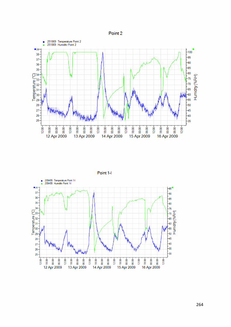
264
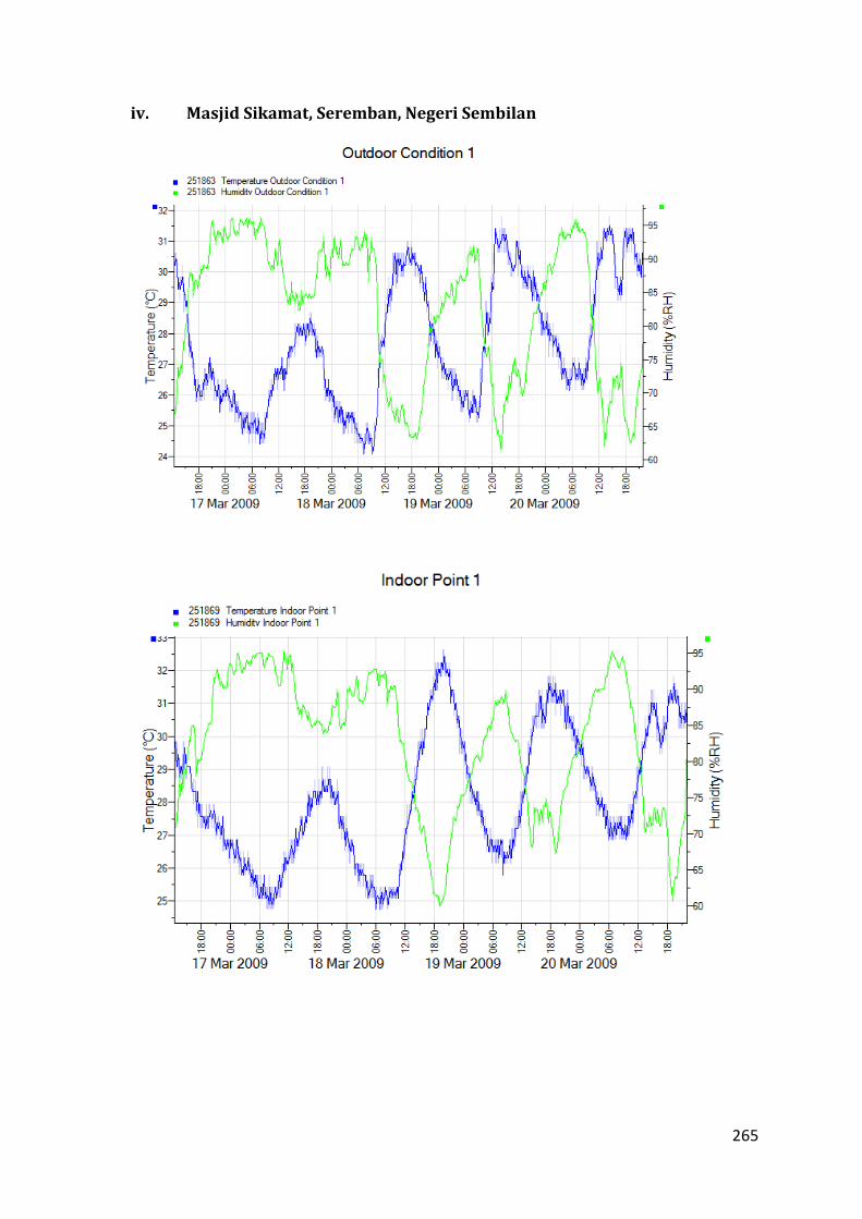
265
iv. Masjid Sikamat, Seremban, Negeri Sembilan
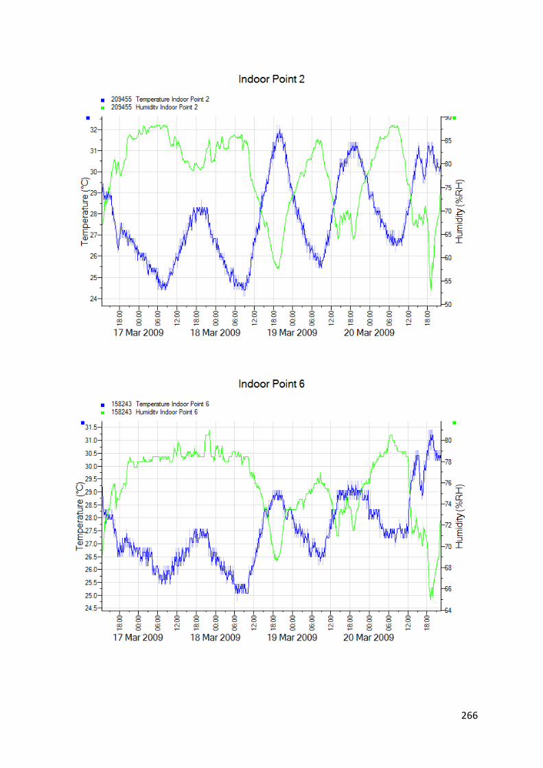
266

267

268
2. COMPILATION OF DATA FROM QUESTIONNAIRE
i. MASJID AL MIZAN, PUTRAJAYA
time Nos. Sex Outdoor
Temp
Indoor
Temp
RH Thermal
Sensation
Comfort
Level
Wind
Condition
Relative
Humidity
Thermal
Pref.
Wind Pref. RH Pref.
1-Male Very Cold -(-3)
Much too Cold (-3)
1- Calm Very dry (-2)
Hotter (1) Breezier (1) Drier (1)
2-Female
Cold - (-2) Too Cold (-2) 2-Breezy Dry (-1) Unchanged(0)
Unchanged (0)
Unchanged(0)
slightly
Cold - (-1)
Comfortably
cool (-1)
3-Very
Windy
Neutral
(0)
Cooler(-1) Calmer(-1) More Humid (-1)
Neutral (0) Comfortable
(2-0)
Humid
(1)
Warm (1) Comfortably
warm (1)
Very
Humid (2)
Hot (2) Too Warm (0 - 2)
Very Hot
(3)
Much too
warm(-1 - 3)
Noon
prayer
1 1 31.4 29.8 74.3 1 2 2 1 -1 1 1
11/4/2009 2 1 31 29.7 74.4 1 1 2 1 -1 1 1
3 1 30.8 29.8 72.3 1 1 1 1 -1 1 1
4 1 31.2 29.6 72.3 1 2 2 1 -1 1 1
5 1 31.6 29.7 73.9 1 1 1 1 -1 1 1
6 1 31.1 29.2 73.1 1 1 1 1 -1 1 1
7 1 31.2 29.8 72.8 1 1 2 1 -1 1 1
Noon prayer
8 1 31 29.7 74.4 2 0 1 2 -1 1 1
12/4/2009 9 1 30.8 29.3 76.1 1 0 1 1 -1 1 1
10 1 31.2 29.8 74.2 1 1 2 1 -1 1 1
11 1 30.4 29.1 76.2 1 1 2 1 -1 1 1

269
12 1 29.3 29.2 86.7 1 1 1 1 -1 1 1
13 1 28.1 28.2 90.5 0 0 1 2 0 1 1
14 1 29.6 29.6 86.7 1 1 2 1 -1 1 1
15 1 26.7 27.2 92 0 0 1 2 0 1 1
16 1 27 26.7 91.8 0 0 1 2 0 1 1
17 1 30.8 29.2 76.2 1 1 1 1 -1 1 1
Noon Prayer
18 1 31.2 29.1 75.6 1 2 2 1 -1 1 1
13/4/2009 19 1 32.6 30.7 69.6 1 2 2 0 -1 1 1
20 1 33.3 30.9 69.9 1 1 1 0 -1 1 1
21 1 33.1 31 69.9 1 1 2 0 -1 1 1
22 1 33.7 31.1 70.4 1 1 1 1 -1 1 1
24 1 33.5 31.3 70.4 1 1 1 1 -1 1 1
24 1 33.9 31.4 70.7 1 1 2 1 -1 1 1
25 1 34.3 31.5 71 1 1 2 1 -1 1 1
26 1 32.1 71.4 2 3 1 1 -1 1 1
27 1 34.3 32.4 72 2 3 2 1 -1 1 1
28 1 34.8 32.5 72.7 2 3 1 2 -1 1 1
29 1 35.4 32.2 73.6 2 3 1 2 -1 1 1
30.06206897
75.69310345
32.5 92
Afternoon 26.7 69.6
11/4/2009 30 1 27.6 °C 27.6 °C 86.1 %RH 1 0 1 2 0 1 1
31 1 27.6 °C 27.9 °C 83.6 %RH 1 1 2 2 0 0 1
32 1 27.6 °C 27.6 °C 83.6 %RH 1 1 2 2 0 0 1
33 1 27.6 °C 27.6 °C 84.1 %RH 1 1 2 2 0 0 1
34 1 27.6 °C 27.2 °C 86.1 %RH 1 0 1 2 -1 1 1
35 1 27.6 °C 26.9 °C 87.1 %RH 0 1 2 2 0 0 1
36 1 27.6 °C 27.2 °C 86.1 %RH 0 1 2 2 0 0 1

270
37 1 27.6 °C 27.6 °C 86.6 %RH 0 1 2 2 0 0 1
38 1 27.6 °C 27.2 °C 88.6 %RH 0 0 1 2 0 1 1
39 1 27.6 °C 27.6 °C 88.6 %RH 0 0 1 2 0 1 1
40 1 27.6 °C 27.6 °C 88.6 %RH 0 0 1 2 0 1 1
12/4/2009 41 1 27.9 °C 27.9 °C 88.6 %RH 0 0 1 2 0 1 1
42 1 27.6 °C 27.2 °C 89.6 %RH 0 0 1 2 0 1 1
43 1 26.9 °C 27.6 °C 89.1 %RH 0 0 1 2 0 1 1
44 1 27.2 °C 27.6 °C 88.6 %RH 0 0 1 2 0 1 1
45 1 27.2 °C 27.2 °C 88.6 %RH 0 0 1 2 0 1 1
46 1 27.2 °C 27.6 °C 89.1 %RH 1 0 1 2 -1 1 1
47 1 27.2 °C 27.6 °C 89.6 %RH 1 0 1 2 -1 1 1
48 1 27.2 °C 27.6 °C 90.1 %RH 1 0 1 2 -1 1 1
49 1 27.6 °C 26.9 °C 89.6 %RH 0 0 1 2 0 1 1
50 1 26.9 °C 26.9 °C 89.6 %RH 0 0 1 2 0 1 1
50 1 26.9 °C 26.9 °C 89.6 %RH 0 0 1 2 0 1 1
52 1 27.2 °C 27.6 °C 89.6 %RH 1 0 1 2 0 1 1
13/4/2009 53 1 38.5 °C 37.0 °C 59.4 %RH 3 3 1 0 -1 1 1
54 1 38.5 °C 37.0 °C 57.9 %RH 3 3 2 0 -1 1 0
55 1 38.0 °C 37.5 °C 57.4 %RH 3 3 2 0 -1 1 0
56 1 38.5 °C 37.5 °C 56.4 %RH 3 3 2 0 -1 1 0
57 1 38.0 °C 37.0 °C 56.4 %RH 3 3 1 0 -1 1 0
58 1 37.5 °C 36.6 °C 49.5 %RH 3 3 2 -1 -1 1 -1
59 1 35.7 °C 36.1 °C 38.6 %RH 3 3 1 -1 -1 1 -1
60 1 34.8 °C 36.6 °C 35.2 %RH 3 3 2 -1 -1 1 -1
61 1 33.9 °C 36.1 °C 33.7 %RH 3 3 2 -1 -1 1 -1
62 1 33.1 °C 36.6 °C 32.2 %RH 3 3 2 -1 -1 1 -1
63 1 32.2 °C 36.1 °C 32.7 %RH 3 3 1 -1 -1 1 -1
64 1 31.8 °C 35.2 °C 36.7 %RH 2 3 2 -1 -1 1 -1
65 1 32.2 °C 34.3 °C 38.6 %RH 2 3 2 -1 -1 1 -1

271
66 1 31.8 °C 34.8 °C 40.1 %RH 2 3 2 -1 -1 1 -1
67 1 31.0 °C 34.8 °C 40.1 %RH 3 3 1 -1 -1 1 -1
30.9 °C 70.7 %RH
37.5 °C 90.1 %RH
26.9 °C 32.2 %RH
Evening
11/4/2009 68 1 26.9 °C 27.6 °C 83.5 %RH 1 2 2 1 0 0 1
69 1 27.2 °C 27.6 °C 83.1 %RH 1 2 2 1 0 0 1
70 1 27.6 °C 27.2 °C 82.6 %RH 1 2 2 1 0 0 1
71 1 26.9 °C 27.2 °C 83.1 %RH 1 2 2 1 0 0 1
72 1 26.9 °C 27.6 °C 83.1 %RH 1 2 2 1 0 0 1
73 1 26.5 °C 27.6 °C 83.5 %RH 1 1 2 1 0 0 1
74 1 26.5 °C 27.6 °C 84.0 %RH 1 2 2 1 0 0 1
75 1 26.9 °C 27.2 °C 84.5 %RH 1 1 2 1 0 0 1
76 1 27.2 °C 27.2 °C 85.9 %RH 1 1 2 1 0 0 1
77 1 26.5 °C 26.9 °C 85.5 %RH 0 1 2 1 0 0 1
78 1 26.9 °C 27.2 °C 85.9 %RH 0 1 2 1 0 0 1
79 1 26.1 °C 27.2 °C 86.4 %RH 1 1 2 1 0 0 1
80 1 26.9 °C 27.2 °C 87.4 %RH 0 2 2 1 0 0 1
81 1 26.9 °C 27.6 °C 87.9 %RH 1 2 2 1 0 0 1
82 1 26.9 °C 26.9 °C 87.9 %RH 0 2 2 1 0 0 1
83 1 26.5 °C 26.5 °C 87.9 %RH 0 2 2 1 0 0 1
84 1 26.9 °C 26.5 °C 88.4 %RH 0 1 2 1 0 0 1
85 1 26.9 °C 26.5 °C 88.4 %RH 0 1 2 1 0 0 1
86 1 26.9 °C 27.2 °C 87.9 %RH 0 1 2 1 0 0 1
87 1 26.5 °C 27.2 °C 87.9 %RH 1 2 2 1 0 0 1
88 1 26.5 °C 26.9 °C 88.4 %RH 0 2 2 1 0 0 1
89 1 26.9 °C 26.5 °C 88.4 %RH 0 2 2 1 0 0 1

272
90 1 26.9 °C 26.9 °C 88.4 %RH 0 2 2 1 0 0 1
91 1 26.9 °C 27.6 °C 88.4 %RH 1 1 2 1 0 0 1
92 1 26.5 °C 26.5 °C 88.4 %RH -1 -1 1 1 0 0 1
12/4/2009 93 1 25.8 °C 26.5 °C 93.1 %RH -1 0 2 1 0 1 1
94 1 25.8 °C 25.8 °C 93.1 %RH -1 0 2 1 0 1 1
95 1 25.8 °C 26.1 °C 93.6 %RH -1 0 2 1 0 1 1
96 1 25.8 °C 25.8 °C 95.1 %RH -1 0 2 1 0 1 1
97 1 25.8 °C 26.1 °C 94.6 %RH -1 0 2 1 0 1 1
98 1 25.8 °C 26.1 °C 94.6 %RH -1 -1 1 1 0 1 1
99 1 25.8 °C 25.8 °C 94.1 %RH -1 -1 1 1 0 1 1
100 1 25.8 °C 26.5 °C 94.6 %RH 0 1 1 1 0 1 1
101 1 25.8 °C 25.4 °C 95.1 %RH -1 -1 1 1 0 1 1
13/4/2009 102 1 28.3 °C 29.8 °C 50.0 %RH 1 1 2 0 -1 1 0
103 1 28.7 °C 29.1 °C 50.0 %RH 1 1 2 0 -1 1 0
104 1 28.3 °C 28.7 °C 50.5 %RH 0 1 2 0 -1 1 0
105 1 27.9 °C 29.1 °C 50.5 %RH 1 1 2 0 -1 1 0
106 1 28.3 °C 29.1 °C 50.5 %RH 1 1 2 0 -1 1 0
107 1 27.9 °C 29.1 °C 51.0 %RH 1 1 2 0 -1 1 0
108 1 27.6 °C 29.1 °C 51.0 %RH 1 1 2 0 -1 1 0
109 1 27.9 °C 28.3 °C 51.5 %RH 0 1 1 0 0 1 0
110 1 28.3 °C 28.7 °C 51.5 %RH 0 1 1 0 0 1 0
111 1 27.9 °C 29.1 °C 51.5 %RH 1 1 1 0 0 1 0
112 1 27.6 °C 28.7 °C 51.5 %RH 1 1 2 0 0 1 0
113 1 28.3 °C 28.3 °C 52.0 %RH 0 1 1 0 0 1 0
114 1 27.6 °C 28.3 °C 52.0 %RH 0 1 1 0 0 1 0
27.4 °C 78.0 %RH 114
29.8 °C 95.1 %RH
25.4 °C 50.0 %RH
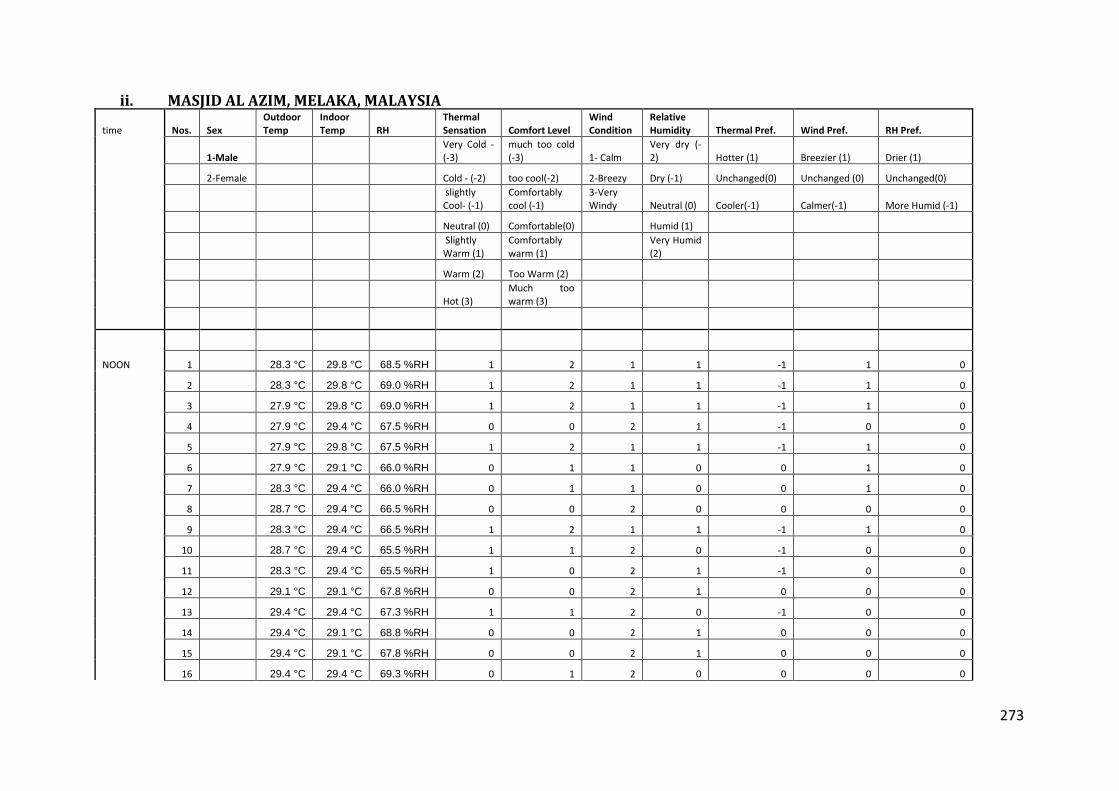
273
ii. MASJID AL AZIM, MELAKA, MALAYSIA
time Nos. Sex Outdoor Temp
Indoor Temp RH
Thermal Sensation Comfort Level
Wind Condition
Relative Humidity Thermal Pref. Wind Pref. RH Pref.
1-Male Very Cold -(-3)
much too cold (-3) 1- Calm
Very dry (-2) Hotter (1) Breezier (1) Drier (1)
2-Female Cold - (-2) too cool(-2) 2-Breezy Dry (-1) Unchanged(0) Unchanged (0) Unchanged(0)
slightly Cool- (-1)
Comfortably cool (-1)
3-Very Windy Neutral (0) Cooler(-1) Calmer(-1) More Humid (-1)
Neutral (0) Comfortable(0) Humid (1)
Slightly Warm (1)
Comfortably warm (1)
Very Humid (2)
Warm (2) Too Warm (2)
Hot (3) Much too warm (3)
NOON 1 28.3 °C 29.8 °C 68.5 %RH 1 2 1 1 -1 1 0
2 28.3 °C 29.8 °C 69.0 %RH 1 2 1 1 -1 1 0
3 27.9 °C 29.8 °C 69.0 %RH 1 2 1 1 -1 1 0
4 27.9 °C 29.4 °C 67.5 %RH 0 0 2 1 -1 0 0
5 27.9 °C 29.8 °C 67.5 %RH 1 2 1 1 -1 1 0
6 27.9 °C 29.1 °C 66.0 %RH 0 1 1 0 0 1 0
7 28.3 °C 29.4 °C 66.0 %RH 0 1 1 0 0 1 0
8 28.7 °C 29.4 °C 66.5 %RH 0 0 2 0 0 0 0
9 28.3 °C 29.4 °C 66.5 %RH 1 2 1 1 -1 1 0
10 28.7 °C 29.4 °C 65.5 %RH 1 1 2 0 -1 0 0
11 28.3 °C 29.4 °C 65.5 %RH 1 0 2 1 -1 0 0
12 29.1 °C 29.1 °C 67.8 %RH 0 0 2 1 0 0 0
13 29.4 °C 29.4 °C 67.3 %RH 1 1 2 0 -1 0 0
14 29.4 °C 29.1 °C 68.8 %RH 0 0 2 1 0 0 0
15 29.4 °C 29.1 °C 67.8 %RH 0 0 2 1 0 0 0
16 29.4 °C 29.4 °C 69.3 %RH 0 1 2 0 0 0 0

274
17 29.4 °C 29.8 °C 67.3 %RH 1 1 2 0 -1 0 0
18 29.4 °C 29.8 °C 65.3 %RH 1 1 2 0 -1 0 0
19 29.4 °C 29.8 °C 67.3 %RH 0 1 2 0 0 0 0
20 29.8 °C 29.8 °C 66.3 %RH 0 0 2 0 0 0 0
21 29.8 °C 29.4 °C 67.8 %RH 0 0 2 0 0 0 0
22 29.8 °C 29.8 °C 67.8 %RH 1 1 1 0 -1 1 0
23 29.4 °C 29.8 °C 66.3 %RH 1 1 1 0 -1 1 0
24 29.8 °C 30.2 °C 67.3 %RH 1 2 1 1 -1 1 0
25 29.8 °C 29.4 °C 67.3 %RH 0 0 2 0 0 0 0
26 29.4 °C 30.2 °C 65.8 %RH 2 2 1 1 -1 1 0
27 29.4 °C 31.4 °C 67.5 %RH 2 2 1 1 -1 1 0
28 29.4 °C 31.0 °C 66.5 %RH 2 2 1 1 -1 1 0
29 29.4 °C 31.4 °C 68.5 %RH 2 2 1 1 -1 1 0
30 29.8 °C 31.4 °C 69.0 %RH 2 2 1 1 -1 1 0
31 29.4 °C 31.0 °C 66.5 %RH 2 2 1 1 -1 1 0
32 29.8 °C 31.4 °C 66.0 %RH 2 2 1 1 -1 1 0
33 29.8 °C 31.4 °C 66.0 %RH 2 2 1 1 -1 1 0
34 29.8 °C 31.8 °C 66.0 %RH 2 2 1 1 -1 1 0
35 29.8 °C 31.8 °C 73.1 %RH 2 2 1 1 -1 1 0
36 30.6 °C 31.4 °C 69.0 %RH 1 2 1 1 -1 1 0
37 30.2 °C 31.0 °C 69.0 %RH 1 2 1 1 -1 1 0
38 30.2 °C 31.0 °C 69.0 %RH 1 1 2 0 -1 0 0
39 30.2 °C 32.2 °C 69.6 %RH 2 2 1 1 -1 1 0
40 30.6 °C 32.2 °C 68.5 %RH 2 2 1 1 -1 1 0
41 30.2 °C 31.0 °C 69.0 %RH 1 1 2 0 -1 0 0
42 30.6 °C 32.2 °C 68.0 %RH 2 2 1 1 -1 1 0
AFTERNOON 43 29.8 °C 29.8 °C 69.5 %RH 1 1 2 0 -1 0 0
44 29.1 °C 29.8 °C 69.0 %RH 1 1 2 0 -1 0 0

275
45 29.1 °C 29.8 °C 69.0 %RH 1 1 2 0 -1 0 0
46 29.4 °C 29.1 °C 69.0 %RH 0 1 2 0 0 0 0
47 30.2 °C 29.4 °C 69.0 %RH 0 0 2 0 0 0 0
48 29.4 °C 29.4 °C 69.0 %RH 0 0 2 0 0 0 0
49 29.4 °C 30.2 °C 81.3 %RH 1 2 1 2 -1 1 -1
50 29.8 °C 30.6 °C 81.3 %RH 1 2 1 2 -1 1 -1
51 29.8 °C 29.8 °C 81.3 %RH 1 2 1 2 -1 1 -1
52 30.2 °C 30.2 °C 81.8 %RH 1 2 1 2 -1 1 -1
53 30.2 °C 30.2 °C 82.9 %RH 1 2 1 2 -1 1 -1
54 29.4 °C 30.2 °C 82.9 %RH 1 2 1 2 -1 1 -1
55 29.8 °C 30.2 °C 82.9 %RH 1 2 1 2 -1 1 -1
56 29.4 °C 30.2 °C 71.9 %RH 1 2 1 1 -1 1 0
57 29.8 °C 30.2 °C 71.9 %RH 1 2 1 1 -1 1 0
58 29.8 °C 30.6 °C 71.9 %RH 1 2 1 1 -1 1 0
59 30.2 °C 30.6 °C 72.8 %RH 1 2 1 1 -1 1 0
60 30.2 °C 30.6 °C 72.8 %RH 1 1 2 0 -1 1 0
61 29.4 °C 30.6 °C 72.8 %RH 1 1 2 0 -1 1 0
62 29.8 °C 30.6 °C 72.4 %RH 1 1 2 0 -1 1 0
63 30.2 °C 30.2 °C 76.3 %RH 1 2 1 1 -1 1 0
64 29.4 °C 30.2 °C 76.3 %RH 1 2 1 1 -1 1 0
65 30.6 °C 30.2 °C 75.8 %RH 1 2 1 1 -1 1 0
66 30.2 °C 30.2 °C 75.8 %RH 1 2 1 1 -1 1 0
EVENING 67 28.7 °C 29.4 °C 75.7 %RH 1 2 1 1 -1 1 0
68 29.1 °C 29.4 °C 75.7 %RH 0 1 2 0 0 1 0
69 29.4 °C 29.4 °C 75.7 %RH 0 1 2 1 0 0 0
70 29.4 °C 28.7 °C 75.7 %RH 0 1 2 1 0 0 0
71 29.1 °C 29.1 °C 75.7 %RH 0 1 2 1 0 0 0
72 28.7 °C 29.4 °C 76.2 %RH 1 2 1 1 -1 1 0
73 29.1 °C 29.1 °C 76.7 %RH 1 2 1 1 -1 1 0
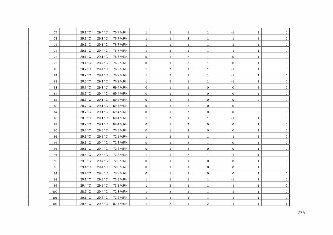
276
74 29.1 °C 29.4 °C 76.7 %RH 1 2 1 1 -1 1 0
75 29.1 °C 29.1 °C 76.7 %RH 1 1 2 1 -1 1 0
76 29.1 °C 29.1 °C 76.7 %RH 1 1 1 1 -1 1 0
77 29.1 °C 29.4 °C 76.7 %RH 1 2 1 1 -1 1 0
78 29.1 °C 29.1 °C 76.7 %RH 0 1 2 1 0 1 0
79 29.1 °C 28.7 °C 76.2 %RH 0 1 2 1 0 1 0
80 28.7 °C 29.4 °C 76.2 %RH 1 2 1 1 -1 1 0
81 28.7 °C 29.4 °C 76.2 %RH 1 2 1 1 -1 1 0
82 28.3 °C 29.1 °C 76.2 %RH 1 2 1 1 -1 1 0
83 28.7 °C 29.1 °C 69.4 %RH 0 1 1 0 0 1 0
84 28.7 °C 29.4 °C 69.4 %RH 0 1 1 0 0 1 0
85 28.3 °C 29.1 °C 69.4 %RH 0 1 2 0 0 0 0
86 28.7 °C 29.1 °C 69.4 %RH 0 1 2 0 0 0 0
87 28.7 °C 29.1 °C 69.4 %RH 0 1 2 0 0 0 0
88 28.3 °C 29.1 °C 69.4 %RH 1 2 1 1 -1 1 0
89 28.7 °C 29.1 °C 69.4 %RH 0 1 2 0 0 1 0
90 29.8 °C 29.8 °C 73.3 %RH 0 1 2 0 0 1 0
91 29.1 °C 29.8 °C 72.8 %RH 1 2 1 1 -1 1 0
92 29.1 °C 29.4 °C 72.8 %RH 0 1 2 1 0 1 0
93 29.1 °C 29.4 °C 72.8 %RH 0 1 2 0 0 1 0
94 29.4 °C 29.8 °C 72.8 %RH 1 1 2 1 -1 1 0
95 29.8 °C 29.4 °C 72.8 %RH 0 1 1 0 0 1 0
96 29.4 °C 29.4 °C 72.8 %RH 0 1 1 0 0 1 0
97 29.4 °C 29.8 °C 73.3 %RH 0 1 1 0 0 1 0
98 29.1 °C 29.8 °C 73.3 %RH 1 2 1 1 -1 1 0
99 29.4 °C 29.8 °C 73.3 %RH 1 2 1 1 -1 1 0
100 28.7 °C 29.4 °C 72.8 %RH 1 2 1 1 -1 1 0
101 29.1 °C 29.8 °C 72.8 %RH 1 2 1 1 -1 1 0
102 29.4 °C 29.8 °C 82.4 %RH 1 2 1 2 -1 1 -1

277
103 29.8 °C 29.8 °C 82.4 %RH 1 2 1 2 -1 1 -1
104 29.4 °C 30.2 °C 82.9 %RH 1 2 1 2 -1 1 -1
105 29.4 °C 29.4 °C 82.9 %RH 1 2 1 2 -1 1 -1
106 29.1 °C 29.8 °C 82.9 %RH 1 2 1 2 -1 1 -1
107 29.4 °C 29.8 °C 82.9 %RH 1 2 1 2 -1 1 -1
108 28.7 °C 29.8 °C 82.4 %RH 1 2 1 2 -1 1 -1
109 29.4 °C 30.6 °C 85.5 %RH 1 2 1 2 -1 1 -1
110 29.8 °C 30.6 °C 85.5 %RH 1 2 1 2 -1 1 -1
111 29.8 °C 30.2 °C 86.0 %RH 1 2 1 2 -1 1 -1
112 29.8 °C 31.0 °C 86.0 %RH 1 2 1 2 -1 1 -1
113 29.8 °C 30.6 °C 86.0 %RH 1 2 1 2 -1 1 -1
114 30.2 °C 30.6 °C 86.0 %RH 1 2 1 2 -1 1 -1
115 29.8 °C 30.6 °C 86.0 %RH 1 2 1 2 -1 1 -1
116 29.4 °C 30.2 °C 86.0 %RH 1 2 1 2 -1 1 -1
117 30.2 °C 30.2 °C 86.0 %RH 1 2 1 2 -1 1 -1
118 30.2 °C 30.2 °C 83.9 %RH 1 2 1 2 -1 1 -1
119 29.4 °C 30.2 °C 81.8 %RH 1 2 1 2 -1 1 -1
120 29.8 °C 30.6 °C 81.3 %RH 1 2 1 2 -1 1 -1

278
iii. MASJID JAMEK, SEREMBAN NEGERI SEMBILAN, MALAYSIA
time Nos. Sex Outdoor Temp
Indoor Temp RH
Thermal Sensation Comfort Level
Wind Condition
Relative Humidity Thermal Pref. Wind Pref. RH Pref.
1-Male Very Cold -(-3)
much too cold (-3) 1- Calm
Very dry (-2) Hotter (1) Breezier (1) Drier (1)
2-Female Cold - (-2) too cool(-2) 2-Breezy Dry (-1) Unchanged(0) Unchanged (0) Unchanged(0)
slightly Cool- (-1)
Comfortably cool (-1)
3-Very Windy Neutral (0) Cooler(-1) Calmer(-1) More Humid (-1)
Neutral (0) Comfortable(0) Humid (1)
Slightly Warm (1)
Comfortably warm (1)
Very Humid (2)
Warm (2) Too Warm (2)
Hot (3) Much too warm (3)
Noon
1 29.1 °C 29.8 °C 69.0 %RH 0 1 2 0 0 0 0
2 28.7 °C 30.2 °C 68.0 %RH 0 0 2 0 0 0 0
3 29.1 °C 30.6 °C 69.6 %RH 0 0 2 0 0 0 0
4 29.4 °C 31.4 °C 68.5 %RH 1 0 2 0 -1 0 0
5 29.1 °C 31.0 °C 68.5 %RH 1 0 2 0 -1 0 0
6 29.4 °C 31.0 °C 68.0 %RH 1 0 2 0 -1 0 0
7 29.8 °C 28.7 °C 71.3 %RH 0 1 1 0 0 1 0
8 29.8 °C 29.4 °C 71.3 %RH 0 1 1 0 0 1 0
9 29.4 °C 29.1 °C 69.8 %RH 0 1 1 0 0 1 0
10 29.1 °C 29.1 °C 68.8 %RH 0 1 1 0 0 1 0
11 29.8 °C 29.4 °C 71.3 %RH 0 1 2 0 0 0 0
12 29.1 °C 29.1 °C 78.7 %RH 0 1 2 0 0 0 0
13 29.1 °C 29.1 °C 77.2 %RH 0 1 2 0 0 0 0
14 29.1 °C 29.1 °C 76.7 %RH 0 1 2 0 0 0 0
15 29.4 °C 28.7 °C 75.7 %RH 0 1 2 0 0 0 0

279
16 29.8 °C 28.7 °C 76.7 %RH 0 1 2 0 0 0 0
17 29.1 °C 28.7 °C 75.7 %RH 0 1 2 0 0 0 0
18 29.1 °C 29.4 °C 74.2 %RH 0 1 2 0 0 0 0
19 29.1 °C 29.4 °C 72.0 %RH 0 1 1 0 0 1 0
20 29.1 °C 30.2 °C 73.0 %RH 1 0 2 0 -1 0 0
21 29.1 °C 30.2 °C 70.6 %RH 1 0 2 0 -1 0 0
22 29.4 °C 30.6 °C 69.2 %RH 1 0 2 0 -1 0 0
23 29.8 °C 30.6 °C 70.6 %RH 1 0 2 0 -1 0 0
24 29.1 °C 30.2 °C 69.2 %RH 0 0 2 0 0 0 0
25 29.1 °C 30.6 °C 68.7 %RH 0 0 1 0 0 1 0
26 27.6 °C 28.3 °C 85.1 %RH 0 0 2 1 0 0 0
27 27.9 °C 29.1 °C 83.6 %RH 0 0 2 1 0 0 0
28 27.9 °C 28.7 °C 82.6 %RH 0 0 2 1 0 0 0
29 28.3 °C 28.7 °C 83.1 %RH 0 0 1 1 0 1 0
30 27.9 °C 29.1 °C 82.6 %RH 0 0 2 1 0 0 0
31 27.9 °C 29.1 °C 80.6 %RH 0 0 1 1 0 1 0
32 27.6 °C 28.3 °C 80.1 %RH 0 0 1 1 0 1 0
33 27.9 °C 29.1 °C 79.1 %RH 0 0 1 1 0 1 0
34 27.9 °C 28.7 °C 78.1 %RH 0 0 2 1 0 0 0
35 27.9 °C 28.7 °C 78.1 %RH 0 0 2 0 0 0 0
36 28.3 °C 26.9 °C 73.9 %RH 0 1 2 0 0 0 0
37 27.9 °C 27.6 °C 74.4 %RH 0 1 2 0 0 0 0
38 27.9 °C 27.6 °C 75.4 %RH 0 1 2 0 0 0 0
39 27.9 °C 27.2 °C 75.9 %RH 0 1 2 0 0 0 0
40 28.3 °C 27.9 °C 75.4 %RH 0 1 2 0 0 0 0
41 28.7 °C 27.9 °C 75.4 %RH 0 1 2 0 0 0 0
42 28.3 °C 27.9 °C 75.4 %RH 0 1 2 0 0 0 0
43 27.9 °C 27.9 °C 75.9 %RH 0 1 2 0 0 0 0
44 28.3 °C 27.6 °C 75.9 %RH 0 1 2 0 0 0 0

280
45 27.9 °C 28.3 °C 75.9 %RH 0 1 2 0 0 0 0
46 27.9 °C 28.3 °C 75.9 %RH 0 1 2 0 0 0 0
47 27.9 °C 27.9 °C 75.9 %RH 0 1 2 0 0 0 0
48 28.7 °C 27.9 °C 75.9 %RH 0 1 2 0 0 0 0
49 28.3 °C 27.9 °C 75.9 %RH 0 1 2 0 0 0 0
50 28.7 °C 27.9 °C 75.9 %RH 0 1 1 0 0 1 0
51 29.1 °C 28.7 °C 75.9 %RH 0 1 2 0 0 0 0
afternoon 52 30.2 °C 31.0 °C 73.6 %RH 1 0 2 1 -1 0 0
53 29.1 °C 29.4 °C 75.6 %RH 0 0 1 0 0 1 0
54 29.4 °C 29.8 °C 74.6 %RH 0 0 1 0 0 1 0
55 29.4 °C 29.1 °C 76.1 %RH 0 0 2 0 0 0 0
56 29.1 °C 27.9 °C 83.1 %RH 0 1 2 0 0 0 0
57 28.3 °C 27.6 °C 87.6 %RH 0 1 2 0 0 0 0
58 28.3 °C 26.9 °C 89.5 %RH 0 1 2 1 0 0 0
59 28.3 °C 27.2 °C 87.6 %RH 0 0 2 1 0 0 0
60 28.3 °C 27.6 °C 81.1 %RH 0 0 2 1 0 0 0
61 27.2 °C 27.6 °C 80.6 %RH 0 0 2 1 0 0 0
62 27.9 °C 27.6 °C 82.1 %RH 0 0 2 1 0 0 0
63 28.3 °C 27.2 °C 82.1 %RH 0 0 2 0 0 0 0
64 28.3 °C 27.9 °C 81.1 %RH 0 0 2 0 0 0 0
65 28.3 °C 27.2 °C 81.1 %RH 0 0 2 0 0 0 0
66 27.9 °C 27.6 °C 81.1 %RH 0 0 2 0 0 0 0
67 29.4 °C 30.2 °C 73.1 %RH 0 0 2 0 0 0 0
68 29.4 °C 30.6 °C 73.6 %RH 1 0 1 0 -1 1 0
69 30.2 °C 30.6 °C 67.0 %RH 1 0 2 0 -1 0 0
70 30.2 °C 30.2 °C 67.5 %RH 1 0 1 0 -1 1 0
71 30.2 °C 31.0 °C 64.5 %RH 1 0 1 0 -1 1 0
72 30.6 °C 31.0 °C 66.0 %RH 1 0 1 0 -1 1 0
73 30.2 °C 31.0 °C 68.0 %RH 1 0 1 0 -1 1 0

281
74 30.2 °C 31.0 °C 66.5 %RH 1 0 1 0 -1 1 0
75 30.6 °C 31.4 °C 65.5 %RH 1 0 1 0 -1 1 0
76 29.8 °C 29.4 °C 73.9 %RH 1 0 1 1 -1 1 0
77 29.8 °C 29.4 °C 73.9 %RH 0 1 1 0 0 1 0
78 29.8 °C 29.1 °C 73.9 %RH 0 1 1 0 0 1 0
79 29.1 °C 29.1 °C 74.4 %RH 0 1 1 0 0 1 0
80 29.4 °C 29.1 °C 73.9 %RH 0 1 2 0 0 0 0
81 29.1 °C 29.1 °C 73.9 %RH 0 1 2 0 0 0 0
82 29.1 °C 29.8 °C 73.9 %RH 0 1 2 0 0 0 0
EVENING 83 27.9 °C 26.5 °C 95.5 %RH 0 -1 1 2 0 0 1
84 27.6 °C 26.5 °C 95.0 %RH 0 0 2 1 0 0 1
85 27.9 °C 26.5 °C 94.5 %RH 0 -1 2 2 0 0 1
86 27.9 °C 26.9 °C 94.0 %RH 0 0 2 1 0 0 0
87 27.6 °C 27.2 °C 94.5 %RH 0 0 2 1 0 0 0
88 27.2 °C 26.9 °C 93.0 %RH 0 0 2 1 0 0 0
89 27.6 °C 26.9 °C 93.0 %RH 0 0 2 2 0 0 0
90 27.2 °C 26.9 °C 93.5 %RH 0 0 2 2 0 0 1
91 27.6 °C 26.5 °C 92.5 %RH 0 0 2 2 0 0 1
92 27.2 °C 26.9 °C 93.0 %RH 0 1 2 1 0 0 1
93 27.2 °C 26.9 °C 93.0 %RH 0 1 2 2 0 0 0
94 27.6 °C 27.2 °C 93.0 %RH 0 0 2 2 0 0 0
95 27.2 °C 27.2 °C 92.5 %RH 0 0 2 2 0 0 1
96 27.2 °C 26.9 °C 92.5 %RH 0 1 2 2 0 0 1
97 27.9 °C 27.2 °C 93.0 %RH 0 1 2 2 0 0 1
98 27.9 °C 27.9 °C 83.1 %RH 0 0 2 1 0 0 1
99 28.3 °C 27.9 °C 82.6 %RH 0 0 2 1 0 0 0
100 27.9 °C 27.9 °C 82.6 %RH 0 0 2 1 0 0 0
101 27.9 °C 27.6 °C 82.1 %RH 0 0 2 1 0 0 0
102 27.6 °C 27.9 °C 82.1 %RH 0 0 2 1 0 0 0

282
103 27.9 °C 27.9 °C 81.6 %RH 0 0 2 1 0 0 0
104 28.3 °C 28.3 °C 81.6 %RH 0 1 2 1 0 0 0
105 28.3 °C 28.3 °C 82.6 %RH 0 0 2 1 0 0 0
106 28.3 °C 27.9 °C 80.6 %RH 0 1 2 1 0 0 0
107 27.9 °C 27.9 °C 77.8 %RH 0 1 2 1 0 0 0
108 27.9 °C 27.6 °C 76.8 %RH 0 1 2 1 0 0 0
109 28.3 °C 27.6 °C 78.2 %RH 0 1 2 1 0 0 0
110 27.2 °C 27.2 °C 78.7 %RH 0 1 2 1 0 0 0
111 27.9 °C 27.2 °C 79.2 %RH 0 1 2 1 0 0 0
112 27.9 °C 26.9 °C 80.6 %RH 0 1 2 1 0 0 0
113 27.9 °C 26.5 °C 80.6 %RH 0 1 2 1 0 0 0
114 27.2 °C 26.5 °C 81.1 %RH 0 1 2 1 0 0 0
115 31.4 °C 32.2 °C 70.3 %RH 2 -1 1 1 -1 1 0
116 31.8 °C 32.2 °C 70.8 %RH 2 -1 1 1 -1 1 0
117 32.2 °C 32.2 °C 70.8 %RH 2 -1 1 1 -1 1 0
118 31.8 °C 32.2 °C 70.3 %RH 2 -1 1 1 -1 1 0
119 31.4 °C 31.8 °C 70.8 %RH 2 -1 1 1 -1 1 0
120 31.8 °C 31.4 °C 71.3 %RH 2 -1 1 1 -1 1 0
121 31.0 °C 31.8 °C 71.3 %RH 2 -1 1 1 -1 1 0
122 31.4 °C 32.2 °C 71.3 %RH 2 -1 1 1 -1 1 0
123 31.4 °C 31.4 °C 72.2 %RH 2 -1 1 1 -1 1 0
124 31.0 °C 31.8 °C 72.2 %RH 2 -1 1 1 -1 1 0
125 31.4 °C 31.8 °C 72.7 %RH 2 -1 1 1 -1 1 0
126 31.8 °C 31.8 °C 72.7 %RH 2 -1 1 1 -1 1 0
127 31.0 °C 31.4 °C 72.2 %RH 1 0 2 1 -1 0 0
128 31.8 °C 31.8 °C 72.2 %RH 2 0 2 1 -1 0 0
129 31.4 °C 31.8 °C 72.2 %RH 2 0 1 1 -1 1 0
130 31.4 °C 31.8 °C 72.2 %RH 2 0 1 1 -1 1 0
131 31.4 °C 32.2 °C 72.2 %RH 2 -1 1 1 -1 1 0
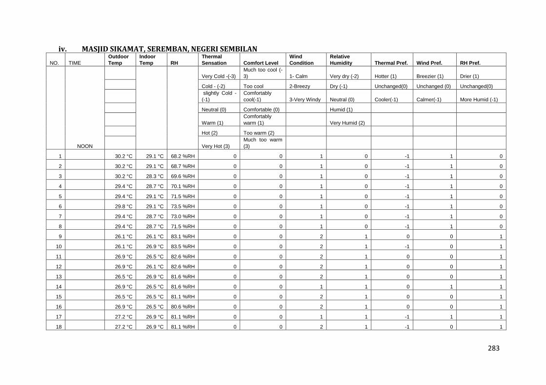
283
iv. MASJID SIKAMAT, SEREMBAN, NEGERI SEMBILAN
NO. TIME
Outdoor
Temp
Indoor
Temp RH
Thermal
Sensation Comfort Level
Wind
Condition
Relative
Humidity Thermal Pref. Wind Pref. RH Pref.
NOON
Very Cold -(-3)
Much too cool (-
3) 1- Calm Very dry (-2) Hotter (1) Breezier (1) Drier (1)
Cold - (-2) Too cool 2-Breezy Dry (-1) Unchanged(0) Unchanged (0) Unchanged(0)
slightly Cold -
(-1)
Comfortably
cool(-1) 3-Very Windy Neutral (0) Cooler(-1) Calmer(-1) More Humid (-1)
Neutral (0) Comfortable (0) Humid (1)
Warm (1)
Comfortably
warm (1) Very Humid (2)
Hot (2) Too warm (2)
Very Hot (3)
Much too warm
(3)
1 30.2 °C 29.1 °C 68.2 %RH 0 0 1 0 -1 1 0
2 30.2 °C 29.1 °C 68.7 %RH 0 0 1 0 -1 1 0
3 30.2 °C 28.3 °C 69.6 %RH 0 0 1 0 -1 1 0
4 29.4 °C 28.7 °C 70.1 %RH 0 0 1 0 -1 1 0
5 29.4 °C 29.1 °C 71.5 %RH 0 0 1 0 -1 1 0
6 29.8 °C 29.1 °C 73.5 %RH 0 0 1 0 -1 1 0
7 29.4 °C 28.7 °C 73.0 %RH 0 0 1 0 -1 1 0
8 29.4 °C 28.7 °C 71.5 %RH 0 0 1 0 -1 1 0
9 26.1 °C 26.1 °C 83.1 %RH 0 0 2 1 0 0 1
10 26.1 °C 26.9 °C 83.5 %RH 0 0 2 1 -1 0 1
11 26.9 °C 26.5 °C 82.6 %RH 0 0 2 1 0 0 1
12 26.9 °C 26.1 °C 82.6 %RH 0 0 2 1 0 0 1
13 26.5 °C 26.9 °C 81.6 %RH 0 0 2 1 0 0 1
14 26.9 °C 26.5 °C 81.6 %RH 0 0 1 1 0 1 1
15 26.5 °C 26.5 °C 81.1 %RH 0 0 2 1 0 0 1
16 26.9 °C 26.5 °C 80.6 %RH 0 0 2 1 0 0 1
17 27.2 °C 26.9 °C 81.1 %RH 0 0 1 1 -1 1 1
18 27.2 °C 26.9 °C 81.1 %RH 0 0 2 1 -1 0 1

284
19 29.4 °C 27.6 °C 78.7 %RH 0 0 1 1 -1 1 1
20 28.7 °C 27.6 °C 78.7 %RH 0 0 1 1 -1 1 1
21 29.4 °C 27.2 °C 78.2 %RH 0 0 2 1 -1 0 1
22 29.4 °C 26.9 °C 78.2 %RH 0 0 2 1 -1 0 1
23 29.4 °C 27.2 °C 79.2 %RH 0 0 2 1 -1 0 1
24 29.4 °C 27.6 °C 78.7 %RH 0 0 1 1 -1 1 1
25 29.8 °C 27.6 °C 78.7 %RH 0 0 1 1 -1 1 1
26 29.8 °C 27.6 °C 78.7 %RH 0 0 2 1 -1 0 1
27 30.6 °C 27.2 °C 78.2 %RH 0 0 2 1 -1 0 1
28 30.2 °C 27.9 °C 76.7 %RH 0 0 2 1 -1 0 1
29 31.0 °C 28.7 °C 68.2 %RH 0 0 1 0 -1 1 0
30 31.0 °C 28.3 °C 66.8 %RH 0 0 2 0 -1 0 0
31 31.0 °C 28.7 °C 66.8 %RH 0 0 1 0 -1 1 0
32 30.6 °C 29.1 °C 66.3 %RH 0 0 2 0 -1 0 0
33 31.0 °C 28.7 °C 66.8 %RH 0 0 2 0 -1 0 0
34 30.6 °C 28.7 °C 66.8 %RH 0 0 2 0 -1 0 0
35 31.0 °C 29.4 °C 67.2 %RH 0 0 2 0 -1 0 0
36 30.6 °C 29.1 °C 67.2 %RH 0 0 2 0 -1 0 0
37 30.6 °C 29.4 °C 65.8 %RH 0 0 2 0 -1 0 0
38 31.4 °C 29.1 °C 64.9 %RH 0 0 1 0 -1 1 0
39 31.0 °C 29.8 °C 64.4 %RH 0 0 2 0 -1 0 0
40 31.0 °C 29.8 °C 63.9 %RH 0 0 1 0 -1 1 0
41 31.8 °C 29.8 °C 63.9 %RH 0 0 1 0 -1 1 0
42 31.4 °C 29.4 °C 72.0 %RH 0 -1 1 1 -1 1 1
43 31.4 °C 29.4 °C 70.5 %RH 0 -1 1 1 -1 1 1
44 31.4 °C 29.4 °C 71.5 %RH 0 -1 1 1 -1 1 1
45 31.0 °C 29.4 °C 71.0 %RH 0 -1 1 1 -1 1 1
46 31.0 °C 29.8 °C 71.5 %RH 0 -1 1 1 -1 1 1
47 31.0 °C 29.8 °C 71.5 %RH 0 -1 1 1 -1 1 1

285
48 31.0 °C 29.4 °C 71.5 %RH 0 -1 1 1 -1 1 1
49 31.4 °C 29.8 °C 71.5 %RH 0 -1 1 1 -1 1 1
50 31.4 °C 30.2 °C 71.5 %RH 1 -1 1 1 -1 1 1
51 31.4 °C 29.8 °C 71.0 %RH 0 -1 1 1 -1 1 1
52 31.0 °C 30.2 °C 71.0 %RH 1 -1 1 1 -1 1 1
53 31.4 °C 30.2 °C 71.5 %RH 1 -1 1 1 -1 1 1
AFTERNOON 27.2 °C 27.6 °C 81.1 %RH 0 1 2 1 -1 0 1
1 26.9 °C 27.6 °C 81.6 %RH 0 1 2 1 -1 0 1
2 27.2 °C 27.2 °C 78.7 %RH 0 1 2 1 -1 0 1
3 27.2 °C 27.2 °C 77.8 %RH 0 1 2 1 -1 0 1
4 26.9 °C 27.2 °C 77.8 %RH 0 1 2 1 -1 0 1
5 26.1 °C 27.2 °C 77.8 %RH 0 1 2 1 -1 0 1
6 26.5 °C 26.9 °C 78.7 %RH 0 1 2 1 -1 0 1
7 26.5 °C 26.5 °C 78.7 %RH 0 1 2 1 -1 0 1
8 26.5 °C 26.9 °C 79.2 %RH 0 1 2 1 -1 0 1
9 28.3 °C 28.3 °C 85.6 %RH 0 1 2 1 -1 0 1
10 28.3 °C 27.6 °C 85.1 %RH 0 1 1 0 -1 1 0
11 27.9 °C 27.9 °C 85.1 %RH 0 1 2 1 -1 0 1
12 28.3 °C 27.9 °C 85.6 %RH 0 1 1 0 -1 1 0
13 28.3 °C 27.9 °C 84.1 %RH 0 1 1 1 -1 1 1
14 28.3 °C 28.3 °C 85.1 %RH 0 1 1 0 -1 1 0
15 27.9 °C 28.3 °C 85.1 %RH 0 1 2 1 -1 0 1
16 27.9 °C 28.3 °C 85.1 %RH 0 1 1 0 -1 1 0
17 27.9 °C 28.3 °C 85.1 %RH 0 1 2 1 -1 0 1
18 30.2 °C 31.0 °C 67.0 %RH 1 2 2 1 -1 0 1
19 30.2 °C 31.0 °C 66.5 %RH 1 2 1 1 -1 1 1
20 30.6 °C 31.0 °C 66.5 %RH 1 2 1 1 -1 1 1

286
21 30.2 °C 30.6 °C 66.5 %RH 1 2 1 1 -1 1 1
22 30.6 °C 30.6 °C 66.5 %RH 1 2 1 1 -1 1 1
23 30.6 °C 31.0 °C 66.0 %RH 1 2 1 1 -1 1 1
24 30.6 °C 31.0 °C 66.0 %RH 1 2 1 1 -1 1 1
25 31.0 °C 31.0 °C 65.5 %RH 1 2 1 1 -1 1 1
26 30.6 °C 31.0 °C 64.5 %RH 1 0 2 1 -1 0 1
27 31.0 °C 31.4 °C 64.5 %RH 1 0 2 1 -1 0 1
28 30.6 °C 31.0 °C 64.0 %RH 1 0 2 1 -1 0 1
29 29.8 °C 30.2 °C 70.6 %RH 1 0 2 1 -1 0 1
30 30.2 °C 30.2 °C 69.6 %RH 1 0 2 1 -1 0 1
31 30.2 °C 30.6 °C 69.2 %RH 1 2 1 1 -1 1 1
32 29.8 °C 30.6 °C 69.2 %RH 1 0 2 1 -1 0 1
33 30.2 °C 30.2 °C 69.6 %RH 1 2 1 1 -1 1 1
34 30.2 °C 31.0 °C 70.1 %RH 1 2 1 2 -1 1 1
35 30.2 °C 31.0 °C 70.1 %RH 1 2 1 2 -1 1 1
36 30.2 °C 30.6 °C 69.6 %RH 1 1 2 1 -1 0 1
37 30.2 °C 31.0 °C 68.7 %RH 1 1 2 1 -1 0 1
EVENING 25.8 °C 27.6 °C 80.2 %RH 1 2 1 1 -1 1 1
1 26.9 °C 26.9 °C 80.6 %RH 0 1 2 1 -1 0 1
2 26.9 °C 27.2 °C 80.6 %RH 0 1 1 0 -1 1 0
3 26.5 °C 27.2 °C 80.6 %RH 0 1 1 0 -1 1 0
4 26.5 °C 26.9 °C 80.6 %RH 0 1 1 0 -1 1 0
5 26.9 °C 27.2 °C 81.1 %RH 0 1 2 1 -1 0 1
6 26.1 °C 26.9 °C 80.6 %RH 0 1 1 0 -1 1 0
7 26.5 °C 26.9 °C 81.1 %RH 0 1 1 0 -1 1 0
8 26.5 °C 27.2 °C 81.6 %RH 0 1 1 0 -1 1 0
9 26.5 °C 27.2 °C 81.6 %RH 0 1 2 1 -1 0 1
10 26.9 °C 27.2 °C 82.1 %RH 0 1 2 1 -1 0 1

287
11 26.9 °C 26.9 °C 83.1 %RH 0 1 1 0 -1 1 0
12 27.2 °C 26.9 °C 83.5 %RH 0 1 1 0 -1 1 0
13 27.2 °C 27.2 °C 85.0 %RH 0 1 2 1 -1 0 1
14 26.5 °C 26.5 °C 85.0 %RH 0 1 2 1 -1 0 1
15 26.5 °C 27.2 °C 85.5 %RH 0 1 2 1 -1 0 1
16 26.5 °C 26.5 °C 85.5 %RH 0 1 2 1 -1 0 1
17 26.9 °C 26.5 °C 85.5 %RH 0 1 2 1 -1 0 1
18 27.2 °C 26.9 °C 85.9 %RH 0 1 2 1 -1 0 1
19 26.9 °C 26.9 °C 85.5 %RH 0 1 2 1 -1 0 1
20 28.3 °C 28.3 °C 84.1 %RH 0 2 1 1 -1 1 1
21 27.9 °C 29.1 °C 84.6 %RH 1 2 1 1 -1 1 1
22 27.9 °C 28.7 °C 85.6 %RH 1 2 1 1 -1 1 1
23 27.2 °C 28.7 °C 85.6 %RH 1 2 1 1 -1 1 1
24 27.2 °C 28.3 °C 85.1 %RH 0 2 1 1 -1 1 1
25 27.2 °C 29.1 °C 85.6 %RH 1 2 1 1 -1 1 1
26 27.9 °C 27.9 °C 85.1 %RH 0 2 1 1 -1 1 1
27 27.6 °C 28.3 °C 85.6 %RH 1 2 1 1 -1 1 1
28 27.2 °C 28.7 °C 86.6 %RH 1 2 1 1 -1 1 1
29 27.6 °C 28.3 °C 87.6 %RH 1 2 1 1 -1 1 1
30 27.9 °C 27.9 °C 87.6 %RH 1 2 1 1 -1 1 1
31 27.2 °C 28.3 °C 88.1 %RH 1 2 1 1 -1 1 1
32 27.6 °C 28.3 °C 87.6 %RH 1 2 1 1 -1 1 1
33 27.2 °C 28.3 °C 87.6 %RH 1 2 1 1 -1 1 1
34 27.2 °C 27.9 °C 87.6 %RH 1 2 1 1 -1 1 1
35 27.6 °C 27.9 °C 87.6 %RH 1 2 1 1 -1 1 1
36 27.2 °C 27.9 °C 87.6 %RH 1 2 1 1 -1 1 1
37 27.6 °C 27.9 °C 87.6 %RH 1 2 1 1 -1 1 1
38 29.8 °C 31.8 °C 58.7 %RH 2 2 2 0 -1 1 0
39 29.4 °C 31.8 °C 58.7 %RH 2 2 2 0 -1 1 0

288
40 30.2 °C 31.8 °C 59.6 %RH 2 2 1 0 -1 1 0
41 30.2 °C 32.2 °C 59.6 %RH 2 2 1 0 -1 1 0
42 29.8 °C 31.8 °C 60.1 %RH 2 2 1 0 -1 1 0
43 29.8 °C 31.4 °C 60.1 %RH 1 2 1 0 -1 1 0
44 29.4 °C 31.4 °C 60.1 %RH 1 2 1 0 -1 1 0
45 29.8 °C 31.8 °C 60.1 %RH 1 2 1 0 -1 1 0
46 29.4 °C 31.8 °C 61.1 %RH 1 2 1 0 -1 1 0
47 29.8 °C 31.8 °C 62.0 %RH 1 2 1 0 -1 1 0
48 29.1 °C 31.4 °C 63.0 %RH 1 2 1 0 -1 1 0
49 29.1 °C 31.8 °C 63.4 %RH 1 2 1 0 -1 1 0
50 29.4 °C 31.4 °C 63.4 %RH 1 2 1 0 -1 1 0
51 29.4 °C 31.8 °C 63.4 %RH 1 1 2 0 -1 0 0
52 29.8 °C 31.0 °C 63.9 %RH 1 1 2 0 -1 0 0
53 29.8 °C 31.0 °C 64.9 %RH 1 1 2 0 -1 0 0
54 29.1 °C 31.4 °C 64.9 %RH 1 1 2 0 -1 0 0
55 29.1 °C 31.0 °C 64.9 %RH 1 1 2 0 -1 0 0
56 28.7 °C 31.4 °C 66.3 %RH 1 1 2 0 -1 0 0
57 29.1 °C 31.0 °C 66.3 %RH 1 1 2 0 -1 0 0
58 29.1 °C 31.4 °C 67.2 %RH 1 1 2 0 -1 0 0
59 29.1 °C 31.4 °C 66.8 %RH 1 1 2 0 -1 0 0
60 29.8 °C 31.4 °C 71.1 %RH 1 2 1 1 -1 1 1
61 29.4 °C 30.6 °C 71.5 %RH 1 2 1 1 -1 1 1
62 30.2 °C 30.6 °C 71.5 %RH 1 2 1 1 -1 1 1
63 29.4 °C 30.6 °C 72.5 %RH 1 1 2 1 -1 0 1
64 29.8 °C 31.0 °C 73.0 %RH 1 1 2 1 -1 0 1
65 29.1 °C 31.0 °C 73.0 %RH 1 1 2 1 -1 0 1
66 29.1 °C 30.6 °C 73.0 %RH 1 2 1 1 -1 1 1
67 29.4 °C 30.6 °C 73.5 %RH 1 2 1 1 -1 1 1
68 29.1 °C 30.2 °C 73.5 %RH 1 2 1 1 -1 1 1
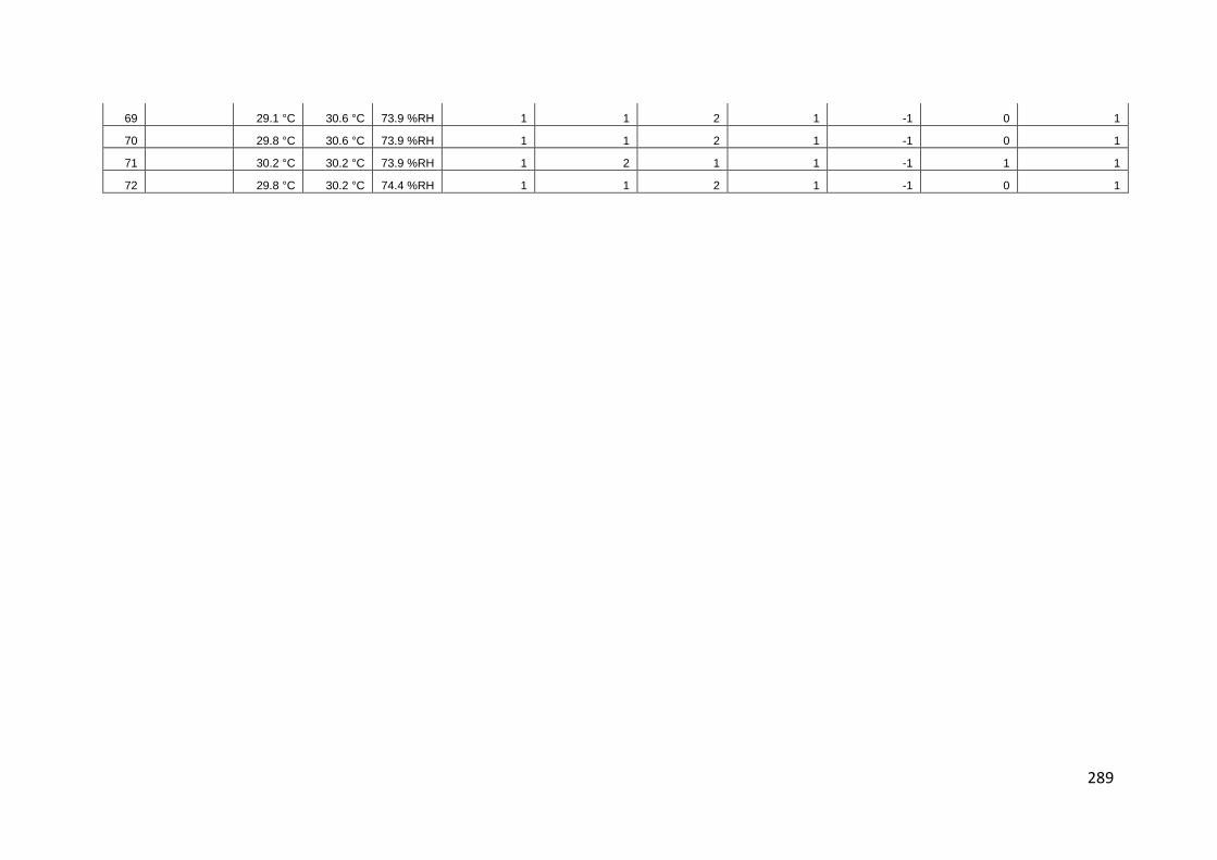
289
69 29.1 °C 30.6 °C 73.9 %RH 1 1 2 1 -1 0 1
70 29.8 °C 30.6 °C 73.9 %RH 1 1 2 1 -1 0 1
71 30.2 °C 30.2 °C 73.9 %RH 1 2 1 1 -1 1 1
72 29.8 °C 30.2 °C 74.4 %RH 1 1 2 1 -1 0 1

290
APPENDIX C
I) HTB2 CODING FOR PITCHED ROOF
METEOROLOGICAL FILE
Climatic data – pitch roof
30101 25.0 24.0 ,, 94 1.5 ,, 0.0 0 ,, 0.8
30102 25.0 23.0 ,, 89 1.5 ,, 0.0 0 ,, 0.8
30103 25.0 23.0 ,, 89 1.0 ,, 0.0 0 ,, 0.8
30104 25.0 23.0 ,, 89 0.5 ,, 0.0 0 ,, 0.8
30105 24.0 23.0 ,, 94 1.0 ,, 0.0 0 ,, 0.8
30106 24.0 23.0 ,, 94 1.0 ,, 0.0 0 ,, 0.8
30107 24.0 23.0 ,, 94 1.5 ,, 105.0 40 ,, 0.8
30108 24.0 23.0 ,, 94 1.5 ,, 250.0 80,, 0.8
30109 26.0 24.0 ,, 89 3.1 ,, 320.0 100,, 0.8
30110 28.0 24.0 ,, 79 3.6 ,, 400.0 120,, 0.8
30111 30.0 24.0 ,, 70 4.6 ,, 450.0 180,, 0.8
30112 31.0 24.0 ,, 66 4.1 ,, 500.0 200,, 0.8
30113 32.0 24.0 ,, 62 3.1 ,, 520.0 220,, 0.8
30114 30.0 24.0 ,, 70 4.1 ,, 550.0 250,, 0.8
30115 30.0 25.0 ,, 74 2.6 ,, 580.0 260,, 0.8
30116 30.0 25.0 ,, 74 2.6 ,, 500.0 210,, 0.8
30117 32.0 24.0 ,, 62 1.5 ,, 320.0 150,, 0.8
30118 31.0 24.0 ,, 66 3.6 ,, 210.0 80,, 0.8
30119 29.0 24.0 ,, 74 2.1 ,, 110.0 40,, 1
30120 26.0 23.0 ,, 83 3.1 ,, 0.0 0,, 1
30121 26.0 24.0 ,, 89 2.1 ,, 0.0 0,, 1
30122 26.0 25.0 ,, 94 2.1 ,, 0.0 0,, 1
30123 25.0 24.0 ,, 94 2.6 ,, 0.0 0,, 1
30124 25.0 24.0 ,, 94 0.0 ,, 0.0 0,, 1
30201 25.0 24.0 ,, 94 1.5 ,, 0.0 0,, 0.8
30202 25.0 24.0 ,, 94 1.5 ,, 0.0 0,, 0.8
30203 25.0 24.0 ,, 94 1.5 ,, 0.0 0,, 0.8
30204 24.0 24.0 ,, 100 0.5 ,, 0.0 0,, 0.8
30205 24.0 24.0 ,, 100 1.5 ,, 0.0 0,, 0.8
30206 24.0 24.0 ,, 100 0.0 ,, 0.0 0,, 0.8
30207 25.0 24.0 ,, 94 1.0 ,, 105.0 40,, 0.8
30208 25.0 24.0 ,, 94 1.5 ,, 250.0 80,, 0.8
30209 26.0 24.0 ,, 89 1.0 ,, 320.0 100,, 0.8
30210 27.0 25.0 ,, 89 3.1 ,, 400.0 120,, 0.8
30211 28.0 25.0 ,, 84 2.6 ,, 450.0 180,, 0.8
30212 30.0 24.0 ,, 70 4.6 ,, 500.0 200,, 0.8
30213 31.0 24.0 ,, 66 3.6 ,, 520.0 220,, 0.8
30214 25.0 24.0 ,, 94 1.5 ,, 550.0 250,, 0.8

291
30215 26.0 24.0 ,, 89 1.0 ,, 580.0 260,, 0.8
30216 27.0 25.0 ,, 89 3.1 ,, 500.0 210,, 0.8
30217 28.0 25.0 ,, 84 2.6 ,, 320.0 150,, 0.8
30218 30.0 24.0 ,, 70 4.6 ,, 210.0 80,, 0.8
30219 31.0 24.0 ,, 66 3.6 ,, 110.0 40,, 0.8
30220 29.0 25.0 ,, 79 2.6 ,, 0.0 0,, 1
30221 28.0 24.0 ,, 79 2.1 ,, 0.0 0,, 0.8
30222 27.0 24.0 ,, 84 2.1 ,, 0.0 0,, 0.8
30223 27.0 24.0 ,, 84 2.1 ,, 0.0 0,, 0.8
30224 27.0 24.0 ,, 84 3.6 ,, 0.0 0,, 0.8
30301 26.0 24.0 ,, 89 4.1 ,, 0.0 0,, 0.8
30302 26.0 24.0 ,, 89 2.6 ,, 0.0 0,, 0.8
30303 26.0 24.0 ,, 89 3.1 ,, 0.0 0,, 0.8
30304 26.0 24.0 ,, 89 4.1 ,, 0.0 0,, 0.8
30305 26.0 24.0 ,, 89 2.6 ,, 0.0 0,, 0.8
30306 26.0 24.0 ,, 89 3.6 ,, 0.0 0,, 0.8
30307 23.0 22.0 ,, 94 3.1 ,, 105.0 40,, 1
30308 23.0 22.0 ,, 94 2.1 ,, 250.0 80,, 1
30309 23.0 22.0 ,, 94 1.0 ,, 320.0 100,, 1
30310 24.0 23.0 ,, 94 0.5 ,, 400.0 120,, 1
30311 25.0 24.0 ,, 94 1.5 ,, 450.0 180,, 0.8
30312 27.0 25.0 ,, 89 2.1 ,, 500.0 200,, 0.8
30313 29.0 25.0 ,, 79 2.1 ,, 520.0 220,, 0.8
30314 30.0 26.0 ,, 79 2.1 ,, 550.0 250,, 0.8
30315 31.0 26.0 ,, 75 1.5 ,, 580.0 260,, 0.8
30316 32.0 26.0 ,, 70 2.1 ,, 500.0 210,, 0.8
30317 25.0 23.0 ,, 89 4.1 ,, 320.0 150,, 1
30318 24.0 23.0 ,, 94 1.5 ,, 210.0 80,, 0.8
30319 25.0 24.0 ,, 94 0.5 ,, 110.0 40,, 0.6
30320 25.0 24.0 ,, 94 0.0 ,, 0.0 0,, 0.8
30321 26.0 25.0 ,, 94 1.0 ,, 0.0 0,, 0.8
30322 26.0 24.0 ,, 89 1.5 ,, 0.0 0,, 0.8
30323 25.0 24.0 ,, 94 1.5 ,, 0.0 0,, 0.8
30324 25.0 24.0 ,, 94 1.5 ,, 0.0 0,, 0.8
30401 25.0 24.0 ,, 94 1.5 ,, 0.0 0,, 0.8
30402 25.0 24.0 ,, 94 1.0 ,, 0.0 0,, 0.8
30403 25.0 24.0 ,, 94 2.1 ,, 0.0 0,, 0.8
30404 25.0 24.0 ,, 94 1.5 ,, 0.0 0,, 1
30405 25.0 23.0 ,, 89 1.0 ,, 0.0 0,, 0.8
30406 25.0 23.0 ,, 89 1.0 ,, 0.0 0,, 0.8
30407 25.0 23.0 ,, 89 1.0 ,, 105.0 40,, 0.8
30408 25.0 23.0 ,, 89 1.5 ,, 250.0 80,, 0.8
30409 26.0 24.0 ,, 89 2.1 ,, 320.0 100,, 0.8
30410 28.0 24.0 ,, 79 2.1 ,, 400.0 120,, 0.8
30411 30.0 24.0 ,, 70 4.6 ,, 450.0 180,, 0.8
30412 30.0 24.0 ,, 70 3.6 ,, 500.0 200,, 0.8
30413 30.0 24.0 ,, 70 3.6 ,, 520.0 220,, 0.8
30414 33.0 24.0 ,, 59 1.5 ,, 550.0 250,, 0.8
30415 32.0 25.0 ,, 66 3.1 ,, 580.0 260,, 0.8
30416 33.0 25.0 ,, 63 4.6 ,, 500.0 210,, 0.8
30417 33.0 23.0 ,, 55 4.1 ,, 320.0 150,, 0.8

292
30418 32.0 23.0 ,, 59 4.1 ,, 210.0 80,, 0.8
30419 31.0 23.0 ,, 62 3.1 ,, 110.0 40,, 0.8
30420 29.0 24.0 ,, 74 1.5 ,, 0.0 0,, 0.8
30421 29.0 25.0 ,, 79 1.0 ,, 0.0 0,, 0.8
30422 29.0 24.0 ,, 74 1.5 ,, 0.0 0,, 0.8
30423 27.0 25.0 ,, 89 1.5 ,, 0.0 0,, 0.8
30424 27.0 25.0 ,, 89 2.1 ,, 0.0 0,, 0.8
30501 27.0 24.0 ,, 84 2.1 ,, 0.0 0,, 0.8
30502 26.0 24.0 ,, 86 3.6 ,, 0.0 0,, 0.4
30503 26.0 24.0 ,, 89 3.1 ,, 0.0 0,, 0.8
30504 26.0 24.0 ,, 89 1.5 ,, 0.0 0,, 0.8
30505 26.0 24.0 ,, 89 2.1 ,, 0.0 0,, 0.8
30506 25.0 24.0 ,, 94 2.1 ,, 0.0 0,, 0.8
30507 25.0 24.0 ,, 94 1.0 ,, 105.0 40,, 0.8
30508 26.0 24.0 ,, 89 1.5 ,, 250.0 80,, 0.8
30509 27.0 24.0 ,, 84 2.6 ,, 320.0 100,, 0.8
30510 28.0 25.0 ,, 84 3.1 ,, 400.0 120,, 0.8
30511 28.0 25.0 ,, 84 2.6 ,, 450.0 180,, 1
30512 28.0 25.0 ,, 84 0.5 ,, 500.0 200,, 1
30513 28.0 25.0 ,, 84 1.0 ,, 520.0 220,, 0.8
30514 28.0 25.0 ,, 84 3.6 ,, 550.0 250,, 1
30515 27.0 25.0 ,, 89 2.6 ,, 580.0 260,, 1
30516 28.0 24.0 ,, 79 3.1 ,, 500.0 210,, 0.8
30517 28.0 24.0 ,, 79 2.6 ,, 320.0 150,, 0.8
30518 28.0 25.0 ,, 84 2.1 ,, 210.0 80,, 0.8
30519 28.0 24.0 ,, 79 3.6 ,, 110.0 40,, 0.8
30520 27.0 24.0 ,, 84 1.5 ,, 0.0 0,, 0.8
30521 27.0 24.0 ,, 84 1.5 ,, 0.0 0,, 0.8
30522 26.0 24.0 ,, 89 1.5 ,, 0.0 0,, 0.8
30523 26.0 23.0 ,, 83 2.1 ,, 0.0 0,, 0.8
30524 26.0 23.0 ,, 83 1.5 ,, 0.0 0,, 0.8
30601 26.0 23.0 ,, 83 1.5 ,, 0.0 0,, 0.8
30602 25.0 24.0 ,, 94 0.5 ,, 0.0 0,, 0.8
30603 25.0 24.0 ,, 94 0.5 ,, 0.0 0,, 0.8
30604 25.0 24.0 ,, 94 1.0 ,, 0.0 0,, 0.8
30605 25.0 24.0 ,, 94 1.0 ,, 0.0 0,, 0.8
30606 24.0 24.0 ,,100 1.5 ,, 0.0 0,, 0.8
30607 24.0 23.0 ,, 94 1.0 ,, 105.0 40,, 0.8
30608 24.0 23.0 ,, 94 1.5 ,, 250.0 80,, 0.8
30609 26.0 24.0 ,, 89 2.1 ,, 320.0 100,, 0.7
30610 26.0 24.0 ,, 89 2.1 ,, 400.0 120,, 0.7
30611 26.0 24.0 ,, 89 2.1 ,, 450.0 180,, 0.7
30612 30.0 25.0 ,, 74 1.5 ,, 500.0 200,, 0.8
30613 31.0 25.0 ,, 70 1.5 ,, 520.0 220,, 0.8
30614 31.0 24.0 ,, 66 2.1 ,, 550.0 250,, 0.8
30615 31.0 25.0 ,, 70 3.1 ,, 580.0 260,, 0.8
30616 32.0 25.0 ,, 66 5.7 ,, 500.0 210,, 0.8
30617 32.0 24.0 ,, 62 4.6 ,, 320.0 150,, 1
30618 32.0 24.0 ,, 62 3.6 ,, 210.0 80,, 0.8
30619 31.0 23.0 ,, 62 3.1 ,, 110.0 40,, 0.8
30620 29.0 24.0 ,, 74 2.1 ,, 0.0 0,, 0.8

293
30621 28.0 24.0 ,, 79 1.5 ,, 0.0 0,, 0.8
30622 28.0 25.0 ,, 84 1.0 ,, 0.0 0,, 0.8
30623 28.0 25.0 ,, 84 1.0 ,, 0.0 0,, 0.8
30624 28.0 25.0 ,, 84 0.0 ,, 0.0 0,, 0.8
30701 28.0 26.0 ,, 89 0.5 ,, 0.0 0,, 0.8
30702 27.0 25.0 ,, 89 0.0 ,, 0.0 0,, 0.8
30703 26.0 25.0 ,, 94 1.0 ,, 0.0 0,, 0.8
30704 26.0 25.0 ,, 94 1.5 ,, 0.0 0,, 0.8
30705 26.0 25.0 ,, 94 0.0 ,, 0.0 0,, 0.8
30706 26.0 25.0 ,, 94 0.0 ,, 0.0 0,, 0.8
30707 26.0 25.0 ,, 94 0.0 ,, 105.0 40,, 1
30708 25.0 24.0 ,, 94 1.5 ,, 250.0 80,, 1
30709 26.0 24.0 ,, 89 0.5 ,, 320.0 100,, 0.8
30710 28.0 25.0 ,, 84 1.0 ,, 400.0 120,, 0.8
30711 30.0 25.0 ,, 74 2.1 ,, 450.0 180,, 0.8
30712 31.0 25.0 ,, 70 1.0 ,, 500.0 200,, 0.8
30713 32.0 25.0 ,, 66 2.1 ,, 520.0 220,, 0.8
30714 32.0 24.0 ,, 57 4.1 ,, 550.0 250,, 0.7
30715 32.0 24.0 ,, 57 4.1 ,, 580.0 260,, 0.7
30716 32.0 24.0 ,, 57 4.1 ,, 500.0 210,, 0.7
30717 32.0 24.0 ,, 57 4.1 ,, 320.0 150,, 0.7
30718 32.0 24.0 ,, 57 4.1 ,, 210.0 80,, 0.7
30719 32.0 24.0 ,, 57 4.1 ,, 110.0 40,, 0.7
30720 26.0 24.0 ,, 90 4.1 ,, 0.0 0,, 1
30721 26.0 24.0 ,, 90 2.1 ,, 0.0 0,, 1
30722 26.0 24.0 ,, 89 0.5 ,, 0.0 0,, 0.8
30723 26.0 24.0 ,, 89 1.0 ,, 0.0 0,, 0.8
30724 25.0 24.0 ,, 94 0.5 ,, 0.0 0,, 0.8
30801 25.0 24.0 ,, 94 1.0 ,, 0.0 0,, 0.8
30802 25.0 24.0 ,, 94 0.0 ,, 0.0 0,, 0.8
30803 24.0 23.0 ,, 94 0.0 ,, 0.0 0,, 0.8
30804 24.0 23.0 ,, 94 0.0 ,, 0.0 0,, 0.8
30805 24.0 23.0 ,, 94 1.5 ,, 0.0 0,, 0.8
30806 24.0 23.0 ,, 94 1.0 ,, 0.0 0,, 0.8
30807 23.0 23.0 ,, 100 1.0 ,, 105.0 40,, 0.8
30808 24.0 23.0 ,, 94 0.0 ,, 250.0 80,, 0.8
30809 26.0 23.0 ,, 83 0.0 ,, 320.0 100,, 0.8
30810 28.0 24.0 ,, 79 0.0 ,, 400.0 120,, 0.8
30811 30.0 23.0 ,, 66 1.5 ,, 450.0 180,, 0.8
30812 31.0 24.0 ,, 66 2.6 ,, 500.0 200,, 0.8
30813 32.0 23.0 ,, 59 4.1 ,, 520.0 220,, 0.8
30814 33.0 24.0 ,, 59 4.6 ,, 500.0 250,, 0.8
30815 33.0 22.0 ,, 52 3.6 ,, 580.0 260,, 0.8
30816 33.0 22.0 ,, 52 3.6 ,, 500.0 210,, 0.8
30817 33.0 21.0 ,, 49 4.1 ,, 320.0 150,, 0.8
30818 32.0 21.0 ,, 52 3.1 ,, 210.0 80,, 0.8
30819 31.0 21.0 ,, 55 3.1 ,, 110.0 40,, 0.8
30820 30.0 21.0 ,, 58 2.1 ,, 0.0 0,, 0.8
30821 28.0 23.0 ,, 74 1.5 ,, 0.0 0,, 0.8
30822 28.0 23.0 ,, 74 1.5 ,, 0.0 0,, 0.8
30823 28.0 22.0 ,, 70 0.0 ,, 0.0 0,, 0.8
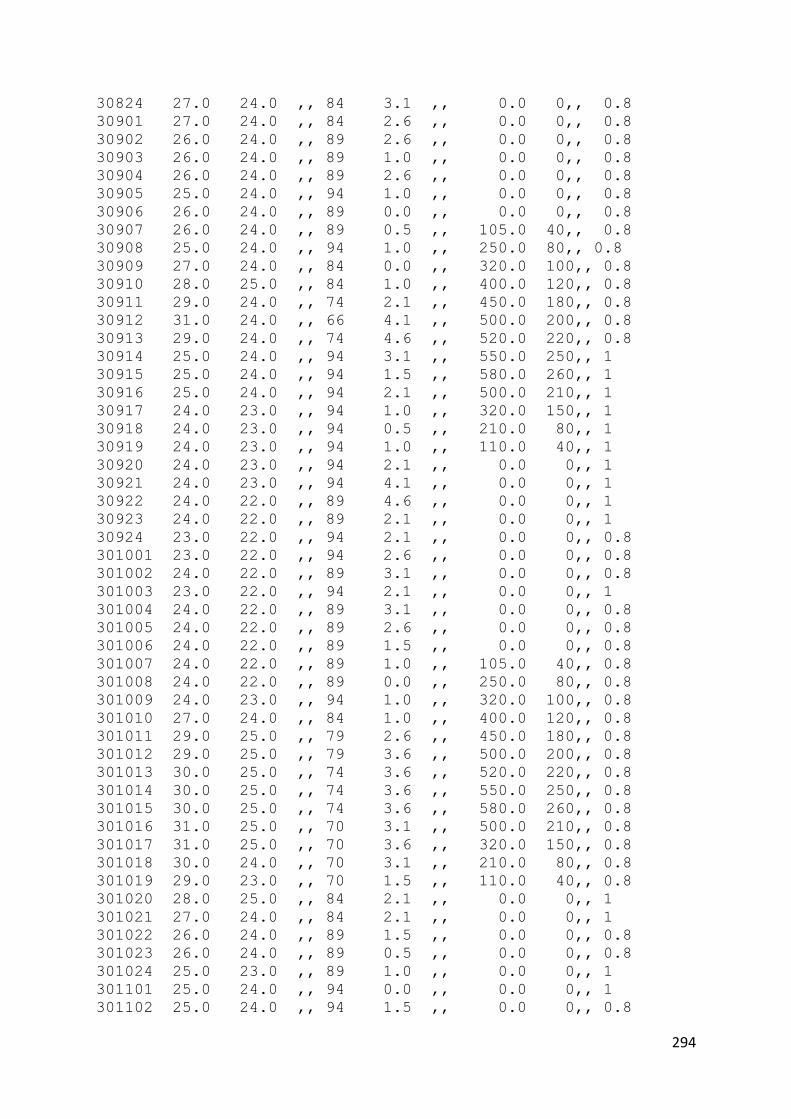
294
30824 27.0 24.0 ,, 84 3.1 ,, 0.0 0,, 0.8
30901 27.0 24.0 ,, 84 2.6 ,, 0.0 0,, 0.8
30902 26.0 24.0 ,, 89 2.6 ,, 0.0 0,, 0.8
30903 26.0 24.0 ,, 89 1.0 ,, 0.0 0,, 0.8
30904 26.0 24.0 ,, 89 2.6 ,, 0.0 0,, 0.8
30905 25.0 24.0 ,, 94 1.0 ,, 0.0 0,, 0.8
30906 26.0 24.0 ,, 89 0.0 ,, 0.0 0,, 0.8
30907 26.0 24.0 ,, 89 0.5 ,, 105.0 40,, 0.8
30908 25.0 24.0 ,, 94 1.0 ,, 250.0 80,, 0.8
30909 27.0 24.0 ,, 84 0.0 ,, 320.0 100,, 0.8
30910 28.0 25.0 ,, 84 1.0 ,, 400.0 120,, 0.8
30911 29.0 24.0 ,, 74 2.1 ,, 450.0 180,, 0.8
30912 31.0 24.0 ,, 66 4.1 ,, 500.0 200,, 0.8
30913 29.0 24.0 ,, 74 4.6 ,, 520.0 220,, 0.8
30914 25.0 24.0 ,, 94 3.1 ,, 550.0 250,, 1
30915 25.0 24.0 ,, 94 1.5 ,, 580.0 260,, 1
30916 25.0 24.0 ,, 94 2.1 ,, 500.0 210,, 1
30917 24.0 23.0 ,, 94 1.0 ,, 320.0 150,, 1
30918 24.0 23.0 ,, 94 0.5 ,, 210.0 80,, 1
30919 24.0 23.0 ,, 94 1.0 ,, 110.0 40,, 1
30920 24.0 23.0 ,, 94 2.1 ,, 0.0 0,, 1
30921 24.0 23.0 ,, 94 4.1 ,, 0.0 0,, 1
30922 24.0 22.0 ,, 89 4.6 ,, 0.0 0,, 1
30923 24.0 22.0 ,, 89 2.1 ,, 0.0 0,, 1
30924 23.0 22.0 ,, 94 2.1 ,, 0.0 0,, 0.8
301001 23.0 22.0 ,, 94 2.6 ,, 0.0 0,, 0.8
301002 24.0 22.0 ,, 89 3.1 ,, 0.0 0,, 0.8
301003 23.0 22.0 ,, 94 2.1 ,, 0.0 0,, 1
301004 24.0 22.0 ,, 89 3.1 ,, 0.0 0,, 0.8
301005 24.0 22.0 ,, 89 2.6 ,, 0.0 0,, 0.8
301006 24.0 22.0 ,, 89 1.5 ,, 0.0 0,, 0.8
301007 24.0 22.0 ,, 89 1.0 ,, 105.0 40,, 0.8
301008 24.0 22.0 ,, 89 0.0 ,, 250.0 80,, 0.8
301009 24.0 23.0 ,, 94 1.0 ,, 320.0 100,, 0.8
301010 27.0 24.0 ,, 84 1.0 ,, 400.0 120,, 0.8
301011 29.0 25.0 ,, 79 2.6 ,, 450.0 180,, 0.8
301012 29.0 25.0 ,, 79 3.6 ,, 500.0 200,, 0.8
301013 30.0 25.0 ,, 74 3.6 ,, 520.0 220,, 0.8
301014 30.0 25.0 ,, 74 3.6 ,, 550.0 250,, 0.8
301015 30.0 25.0 ,, 74 3.6 ,, 580.0 260,, 0.8
301016 31.0 25.0 ,, 70 3.1 ,, 500.0 210,, 0.8
301017 31.0 25.0 ,, 70 3.6 ,, 320.0 150,, 0.8
301018 30.0 24.0 ,, 70 3.1 ,, 210.0 80,, 0.8
301019 29.0 23.0 ,, 70 1.5 ,, 110.0 40,, 0.8
301020 28.0 25.0 ,, 84 2.1 ,, 0.0 0,, 1
301021 27.0 24.0 ,, 84 2.1 ,, 0.0 0,, 1
301022 26.0 24.0 ,, 89 1.5 ,, 0.0 0,, 0.8
301023 26.0 24.0 ,, 89 0.5 ,, 0.0 0,, 0.8
301024 25.0 23.0 ,, 89 1.0 ,, 0.0 0,, 1
301101 25.0 24.0 ,, 94 0.0 ,, 0.0 0,, 1
301102 25.0 24.0 ,, 94 1.5 ,, 0.0 0,, 0.8

295
301103 25.0 24.0 ,, 94 2.1 ,, 0.0 0,, 0.8
301104 25.0 24.0 ,, 94 1.5 ,, 0.0 0,, 0.8
301105 25.0 24.0 ,, 94 1.5 ,, 0.0 0,, 0.8
301106 25.0 24.0 ,, 94 1.0 ,, 0.0 0,, 0.8
301107 25.0 24.0 ,, 94 1.5 ,, 105.0 40,, 0.8
301108 26.0 24.0 ,, 89 1.5 ,, 250.0 100,, 0.8
301109 27.0 24.0 ,, 84 3.1 ,, 320.0 120,, 0.8
301110 29.0 24.0 ,, 74 3.6 ,, 400.0 160,, 0.8
301111 29.0 24.0 ,, 74 3.6 ,, 450.0 200,, 0.8
301112 31.0 23.0 ,, 62 1.5 ,, 550.0 250,, 0.8
301113 31.0 25.0 ,, 70 1.5 ,, 620.0 285,, 0.8
301114 29.0 25.0 ,, 79 4.1 ,, 680.0 320,, 0.8
301115 27.0 24.0 ,, 84 4.1 ,, 720.0 350,, 1
301116 27.0 24.0 ,, 84 2.1 ,, 600.0 250,, 1
301117 27.0 24.0 ,, 84 1.5 ,, 420.0 180,, 0.8
301118 27.0 25.0 ,, 89 1.5 ,, 210.0 80,, 0.8
301119 26.0 23.0 ,, 83 3.6 ,, 110.0 40,, 0.8
301120 25.0 23.0 ,, 89 1.5 ,, 0.0 0,, 1
301121 25.0 23.0 ,, 89 1.5 ,, 0.0 0,, 0.8
301122 25.0 23.0 ,, 89 1.5 ,, 0.0 0,, 0.8
301123 24.0 23.0 ,, 94 2.6 ,, 0.0 0,, 0.8
301124 27.0 24.0 ,, 84 3.1 ,, 0.0 0,, 0.8
301201 27.0 24.0 ,, 84 2.6 ,, 0.0 0,, 0.8
301202 26.0 24.0 , , 89 2.6 , , 0.0 0 , ,
0.8
301203 26.0 24.0 , , 89 1.0 , , 0.0 0
, , 0.8
301204 26.0 24.0 , , 89 2.6 , , 0.0 0 ,
, 0.8
301205 25.0 24.0 , , 94 1.0 , , 0.0 0 ,
, 0.8
301206 26.0 24.0 , , 89 0.0 , , 0.0 0 ,
, 0.8
301207 26.0 24.0 , , 89 0.5 , , 105.0 40
, , 0.8
301208 25.0 24.0 , , 94 1.0 , , 250.0
100 , , 0.8
301209 27.0 24.0 , , 84 0.0 , , 320.0
120 , , 0.8
301210 28.0 25.0 , , 84 1.0 , , 400.0
160 , , 0.8
301211 29.0 24.0 , , 74 2.1 , , 520.0
200 , , 0.8
301212 31.0 24.0 , , 66 4.1 , , 650.0
250 , , 0.8
301213 29.0 24.0 , , 74 4.6 , , 720.0
285 , , 0.8
301214 25.0 24.0 , , 94 3.1 , , 800.0
320 , , 1
301215 25.0 24.0 , , 94 1.5 , , 820.0
350 , , 1

296
301216 25.0 24.0 , , 94 2.1 , , 600.0
250 , , 1
301217 24.0 23.0 , , 94 1.0 , , 420.0
180 , , 1
301218 24.0 23.0 , , 94 0.5 , , 210.0 80
, , 1
301219 24.0 23.0 , , 94 1.0 , , 110.0 40
, , 1
301220 24.0 23.0 , , 94 2.1 , , 0.0 0 ,
, 1
301221 24.0 23.0 , , 94 4.1 , , 0.0 0 ,
, 1
301222 24.0 22.0 , , 89 4.6 , , 0.0 0 ,
, 1
301223 24.0 22.0 , , 89 2.1 , , 0.0 0 ,
, 1
301224 23.0 22.0 , , 94 2.1 , , 0.0 0 ,
, 0.8
301301 23.0 22.0 , , 94 2.6 , , 0.0 0 ,
, 0.8
301302 24.0 22.0 , , 89 3.1 , , 0.0 0 ,
, 0.8
301303 23.0 22.0 , , 94 2.1 , , 0.0 0 ,
, 1
301304 24.0 22.0 , , 89 3.1 , , 0.0 0 , ,
0.8
301305 24.0 22.0 , , 89 2.6 , , 0.0 0 ,
, 0.8
301306 24.0 22.0 , , 89 1.5 , , 0.0 0 ,
, 0.8
301307 24.0 22.0 , , 89 1.0 , , 105.0 40
, , 0.8
301308 24.0 22.0 , , 89 0.0 , , 250.0
100 , , 0.8
301309 24.0 23.0 , , 94 1.0 , , 320.0
120 , , 0.8
301310 27.0 24.0 , , 84 1.0 , , 400.0
160 , , 0.8
301311 29.0 25.0 , , 79 2.6 , , 520.0
200 , , 0.8
301312 29.0 25.0 , , 79 3.6 , , 650.0
250 , , 0.8
301313 30.0 25.0 , , 74 3.6 , , 720.0
285 , , 0.8
301314 30.0 25.0 , , 74 3.6 , , 800.0
320 , , 0.8
301315 30.0 25.0 , , 74 3.6 , , 820.0
350 , , 0.8
301316 31.0 25.0 , , 70 3.1 , , 600.0
250 , , 0.8

297
301317 31.0 25.0 , , 70 3.6 , , 420.0
180 , , 0.8
301318 30.0 24.0 , , 70 3.1 , , 210.0 80
, , 0.8
301319 29.0 23.0 , , 70 1.5 , , 110.0 40
, , 0.8
301320 28.0 25.0 , , 84 2.1 , , 0.0 0 ,
, 1
301321 27.0 24.0 , , 84 2.1 , , 0.0 0 ,
, 1
301322 26.0 24.0 , , 89 1.5 , , 0.0 0 ,
, 0.8
301323 26.0 24.0 , , 89 0.5 , , 0.0 0 ,
, 0.8
301324 24.0 23.0 , , 94 1.0 , , 0.0 0 ,
, 0.8
301401 24.0 23.0 , , 94 1.0 , , 0.0 0 ,
, 0.8
301402 24.0 23.0 , , 94 1.5 , , 0.0 0 ,
, 0.8
301403 24.0 23.0 , , 94 0.0 , , 0.0 0 ,
, 0.8
301404 24.0 23.0 , , 94 0.5 , , 0.0 0 ,
, 0.8
301405 25.0 23.0 , , 89 0.0 , , 0.0 0 ,
, 0.8
301406 25.0 23.0 , , 89 1.0 , , 0.0 0 ,
, 0.8
301407 25.0 23.0 , , 89 0.0 , , 105.0 40
, , 0.8
301408 24.0 23.0 , , 94 2.1 , , 250.0
100 , , 1
301409 25.0 23.0 , , 89 2.6 , , 320.0
120 , , 0.8
301410 27.0 23.0 , , 79 2.1 , , 400.0
160 , , 0.8
301411 28.0 23.0 , , 74 2.6 , , 520.0
200 , , 0.8
301412 30.0 24.0 , , 70 1.5 , , 650.0
250 , , 0.8
301413 31.0 24.0 , , 66 1.0 , , 720.0
285 , , 0.8
301414 30.0 25.0 , , 74 5.7 , , 800.0
320 , , 0.8
301415 31.0 25.0 , , 70 4.1 , , 820.0
350 , , 0.8
301416 31.0 25.0 , , 70 5.7 , , 600.0
250 , , 0.8
301417 30.0 24.0 , , 70 4.6 , , 420.0
180 , , 1
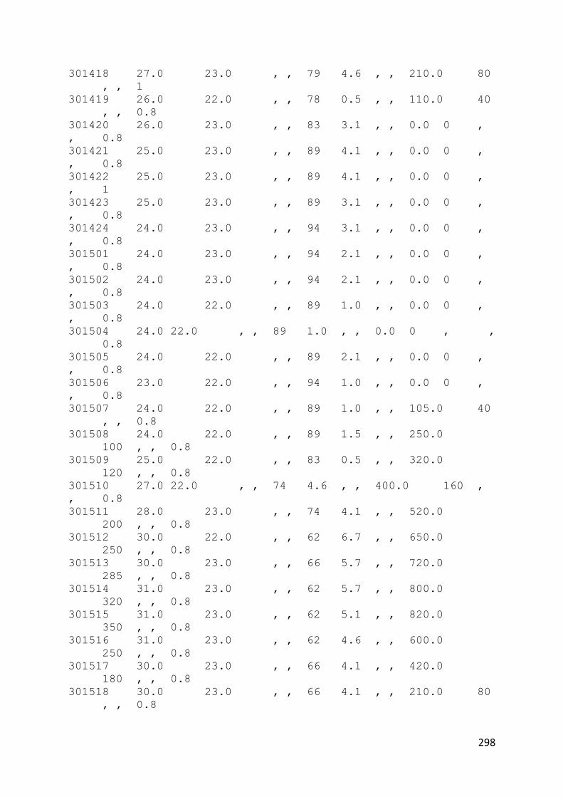
298
301418 27.0 23.0 , , 79 4.6 , , 210.0 80
, , 1
301419 26.0 22.0 , , 78 0.5 , , 110.0 40
, , 0.8
301420 26.0 23.0 , , 83 3.1 , , 0.0 0 ,
, 0.8
301421 25.0 23.0 , , 89 4.1 , , 0.0 0 ,
, 0.8
301422 25.0 23.0 , , 89 4.1 , , 0.0 0 ,
, 1
301423 25.0 23.0 , , 89 3.1 , , 0.0 0 ,
, 0.8
301424 24.0 23.0 , , 94 3.1 , , 0.0 0 ,
, 0.8
301501 24.0 23.0 , , 94 2.1 , , 0.0 0 ,
, 0.8
301502 24.0 23.0 , , 94 2.1 , , 0.0 0 ,
, 0.8
301503 24.0 22.0 , , 89 1.0 , , 0.0 0 ,
, 0.8
301504 24.0 22.0 , , 89 1.0 , , 0.0 0 , ,
0.8
301505 24.0 22.0 , , 89 2.1 , , 0.0 0 ,
, 0.8
301506 23.0 22.0 , , 94 1.0 , , 0.0 0 ,
, 0.8
301507 24.0 22.0 , , 89 1.0 , , 105.0 40
, , 0.8
301508 24.0 22.0 , , 89 1.5 , , 250.0
100 , , 0.8
301509 25.0 22.0 , , 83 0.5 , , 320.0
120 , , 0.8
301510 27.0 22.0 , , 74 4.6 , , 400.0 160 ,
, 0.8
301511 28.0 23.0 , , 74 4.1 , , 520.0
200 , , 0.8
301512 30.0 22.0 , , 62 6.7 , , 650.0
250 , , 0.8
301513 30.0 23.0 , , 66 5.7 , , 720.0
285 , , 0.8
301514 31.0 23.0 , , 62 5.7 , , 800.0
320 , , 0.8
301515 31.0 23.0 , , 62 5.1 , , 820.0
350 , , 0.8
301516 31.0 23.0 , , 62 4.6 , , 600.0
250 , , 0.8
301517 30.0 23.0 , , 66 4.1 , , 420.0
180 , , 0.8
301518 30.0 23.0 , , 66 4.1 , , 210.0 80
, , 0.8

299
301519 28.0 22.0 , , 70 5.7 , , 110.0 40
, , 0.8
301520 26.0 23.0 , , 83 4.6 , , 0.0 0
, , 0.8
301521 26.0 23.0 , , 83 4.1 , , 0.0 0 ,
, 0.8
301522 26.0 23.0 , , 83 3.1 , , 0.0 0 ,
, 0.8
301523 25.0 23.0 , , 89 3.1 , , 0.0 0 ,
, 0.8
301524 25.0 23.0 , , 89 2.1 , , 0.0 0 ,
, 0.8
301601 25.0 23.0 , , 89 3.6 , , 0.0 0 ,
, 0.8
301602 25.0 23.0 , , 89 4.1 , , 0.0 0 , ,
0.8
301603 25.0 23.0 , , 89 2.6 , , 0.0 0 ,
, 0.8
301604 25.0 23.0 , , 89 3.1 , , 0.0 0 ,
, 0.8
301605 25.0 23.0 , , 89 2.1 , , 0.0 0 ,
, 0.8
301606 25.0 23.0 , , 89 1.5 , , 0.0 0 ,
, 0.8
301607 25.0 23.0 , , 89 2.6 , , 105.0 40 ,
, 0.8
301608 25.0 23.0 , , 89 2.1 , , 250.0
100 , , 0.8
301609 26.0 23.0 , , 83 2.6 , , 320.0
120 , , 0.8
301610 28.0 23.0 , , 74 3.6 , , 400.0
160 , , 0.8
301611 29.0 23.0 , , 70 4.1 , , 520.0
200 , , 0.8
301612 30.0 23.0 , , 66 3.1 , , 650.0
250 , , 0.8
301613 30.0 23.0 , , 66 1.5 , , 720.0
285 , , 0.8
301614 30.0 23.0 , , 66 3.1 , , 800.0
320 , , 0.8
301615 27.0 23.0 , , 79 3.6 , , 820.0
350 , , 0.8
301616 26.0 23.0 , , 83 2.1 , , 600.0
250 , , 1
301617 26.0 23.0 , , 83 1.5 , , 420.0
180 , , 0.8
301618 26.0 24.0 , , 89 1.5 , , 210.0 80 ,
, 1
301619 26.0 24.0 , , 89 1.5 , , 110.0 40
, , 1

300
301620 25.0 24.0 , , 94 0.5 , , 0.0 0 ,
, 1
301621 25.0 24.0 , , 94 2.1 , , 0.0 0 ,
, 0.8
301622 25.0 23.0 , , 89 2.1 , , 0.0 0 ,
, 0.8
301623 25.0 23.0 , , 89 2.1 , , 0.0 0 ,
, 0.8
301624 25.0 23.0 , , 89 2.1 , , 0.0 0 ,
, 0.8
301701 25.0 23.0 , , 89 1.5 , , 0.0 0 ,
, 0.8
301702 25.0 23.0 , , 89 2.6 , , 0.0 0
, , 0.8
301703 24.0 23.0 , , 94 1.5 , , 0.0 0 , ,
0.8
301704 24.0 23.0 , , 94 2.1 , , 0.0 0 ,
, 0.8
301705 24.0 23.0 , , 94 1.5 , , 0.0 0 ,
, 0.8
301706 24.0 23.0 , , 94 2.1 , , 0.0 0 , ,
0.8
301707 24.0 23.0 , , 94 2.6 , , 105.0 40
, , 1
301708 24.0 23.0 , , 94 1.5 , , 250.0
100 , , 0.8
301709 24.0 23.0 , , 94 2.1 , , 320.0
120 , , 1
301710 25.0 23.0 , , 89 2.6 , , 400.0
160 , , 0.8
301711 27.0 23.0 , , 79 2.1 , , 520.0
200 , , 0.8
301712 26.0 24.0 , , 89 1.5 , , 650.0
250 , , 1
301713 28.0 24.0 , , 79 1.5 , , 720.0
285 , , 0.8
301714 30.0 23.0 , , 66 1.0 , , 800.0
320 , , 0.8
301715 31.0 25.0 , , 70 3.6 , , 820.0
350 , , 0.8
301716 31.0 24.0 , , 66 3.1 , , 600.0 250 ,
, 0.8
301717 31.0 23.0 , , 62 2.6 , , 420.0
180 , , 0.8
301718 31.0 24.0 , , 66 1.5 , , 210.0 80 ,
, 0.8
301719 30.0 23.0 , , 66 2.1 , , 110.0 40
, , 0.8
301720 29.0 24.0 , , 74 1.5 , , 0.0 0 ,
, 0.8

301
301721 28.0 24.0 , , 79 1.0 , , 0.0 0 ,
, 0.8
301722 27.0 24.0 , , 84 1.0 , , 0.0 0 , ,
0.8
301723 27.0 24.0 , , 84 0.5 , , 0.0 0 ,
, 0.8
301724 26.0 24.0 , , 89 0.5 , , 0.0 0
, , 0.8
301801 26.0 24.0 , , 89 1.5 , , 0.0 0 , ,
0.8
301802 26.0 24.0 , , 89 1.5 , , 0.0 0
, , 0.8
301803 26.0 23.0 , , 83 1.5 , , 0.0 0 , ,
0.8
301804 25.0 23.0 , , 89 1.5 , , 0.0 0 ,
, 0.8
301805 25.0 23.0 , , 89 0.0 , , 0.0 0 , ,
0.8
301806 25.0 23.0 , , 89 0.5 , , 0.0 0 ,
, 0.8
301807 25.0 23.0 , , 89 0.0 , , 105.0 40
, , 0.8
301808 25.0 23.0 , , 89 1.0 , , 250.0
100 , , 0.8
301809 26.0 23.0 , , 83 3.1 , , 320.0 120 ,
, 0.8
301810 27.0 23.0 , , 79 1.0 , , 400.0 160 ,
, 0.8
301811 29.0 23.0 , , 70 1.0 , , 520.0
200 , , 0.8
301812 31.0 23.0 , , 62 2.1 , , 650.0
250 , , 0.8
301813 31.0 24.0 , , 66 4.1 , , 720.0
285 , , 0.8
301814 32.0 24.0 , , 62 3.6 , , 800.0
320 , , 0.8
301815 32.0 24.0 , , 62 5.1 , , 820.0
350 , , 0.8
301816 33.0 24.0 , , 59 4.1 , , 600.0
250 , , 0.8
301817 33.0 23.0 , , 55 4.1 , , 420.0
180 , , 0.8
301818 32.0 23.0 , , 59 3.6 , , 210.0 80
, , 0.8
301819 31.0 23.0 , , 62 3.1 , , 110.0 40
, , 0.8
301820 30.0 23.0 , , 66 2.1 , , 0.0 0 ,
, 0.8
301821 29.0 23.0 , , 70 1.0 , , 0.0 0 ,
, 0.8

302
301822 29.0 24.0 , , 74 0.0 , , 0.0 0 ,
, 0.8
301823 28.0 24.0 , , 79 0.0 , , 0.0 0 ,
, 0.8
301824 27.0 24.0 , , 84 0.5 , , 0.0 0 ,
, 0.8
301901 26.0 24.0 , , 89 0.5 , , 0.0 0 ,
, 0.8
301902 26.0 24.0 , , 89 0.5 , , 0.0 0 ,
, 0.8
301903 27.0 23.0 , , 79 2.1 , , 0.0 0 ,
, 0.8
301904 26.0 23.0 , , 83 0.0 , , 0.0 0 ,
, 1
301905 26.0 24.0 , , 89 0.5 , , 0.0 0 ,
, 1
301906 25.0 24.0 , , 94 0.5 , , 0.0 0 , ,
0.8
301907 25.0 24.0 , , 94 1.5 , , 105.0 40
, , 0.8
301908 25.0 24.0 , , 94 1.0 , , 250.0
100 , , 0.8
301909 27.0 24.0 , , 84 2.1 , , 320.0
120 , , 0.8
301910 29.0 25.0 , , 79 3.6 , , 400.0
160 , , 0.8
301911 30.0 24.0 , , 70 3.1 , , 520.0
200 , , 0.8
301912 32.0 24.0 , , 62 3.6 , , 650.0
250 , , 0.8
301913 31.0 25.0 , , 70 1.5 , , 720.0
285 , , 0.8
301914 32.0 25.0 , , 66 2.6 , , 800.0
320 , , 0.8
301915 30.0 25.0 , , 74 5.1 , , 820.0
350 , , 0.8
301916 30.0 25.0 , , 74 3.1 , , 600.0
250 , , 1
301917 30.0 24.0 , , 70 3.6 , , 420.0
180 , , 1
301918 30.0 24.0 , , 70 3.1 , , 210.0 80
, , 0.8
301919 30.0 24.0 , , 70 2.6 , , 110.0 40 ,
, 0.8
301920 29.0 24.0 , , 74 1.0 , , 0.0 0 ,
, 0.8
301921 29.0 25.0 , , 79 0.0 , , 0.0 0 ,
, 0.8
301922 28.0 25.0 , , 84 1.0 , , 0.0 0 ,
, 0.8

303
301923 27.0 25.0 , , 89 1.5 , , 0.0 0 ,
, 0.8
301924 27.0 25.0 , , 89 0.5 , , 0.0 0 , ,
0.8
302001 26.0 25.0 , , 94 1.5 , , 0.0 0 ,
, 0.8
302002 26.0 24.0 , , 89 1.5 , , 0.0 0 , , 1
302003 26.0 25.0 , , 94 0.0 , , 0.0 0 ,
, 1
302004 24.0 22.0 , , 89 2.1 , , 0.0 0 ,
, 1
302005 25.0 23.0 , , 89 0.5 , , 0.0 0 ,
, 1
302006 24.0 23.0 , , 94 1.0 , , 0.0 0 ,
, 1
302007 24.0 23.0 , , 94 1.5 , , 105.0 40
, , 0.8
302008 25.0 23.0 , , 89 1.5 , , 250.0
100 , , 0.8
302009 26.0 24.0 , , 89 2.6 , , 320.0
120 , , 0.8
302010 28.0 25.0 , , 84 2.1 , , 400.0
160 , , 0.8
302011 30.0 25.0 , , 74 1.0 , , 520.0
200 , , 0.8
302012 32.0 25.0 , , 66 1.5 , , 650.0
250 , , 0.8
302013 31.0 26.0 , , 75 4.1 , , 720.0
285 , , 0.8
302014 29.0 25.0 , , 79 3.1 , , 800.0
320 , , 1
302015 29.0 24.0 , , 74 0.5 , , 820.0 350 ,
, 1
302016 28.0 25.0 , , 84 1.5 , , 600.0
250 , , 0.8
302017 28.0 25.0 , , 84 3.1 , , 420.0
180 , , 0.8
302018 28.0 25.0 , , 84 1.0 , , 210.0 80
, , 0.8
302019 28.0 25.0 , , 84 1.5 , , 110.0 40
, , 0.8
302020 27.0 25.0 , , 89 0.5 , , 0.0 0 ,
, 0.8
302021 27.0 25.0 , , 89 0.5 , , 0.0 0 ,
, 0.8
302022 27.0 25.0 , , 89 1.5 , , 0.0 0 ,
, 0.8
302023 26.0 25.0 , , 94 0.0 , , 0.0 0 ,
, 0.8
302024 26.0 24.0 , , 89 4.1 , , 0.0 0 ,
, 0.8

304
302101 25.0 23.0 , , 89 1.5 , , 0.0 0 , ,
0.8
302102 25.0 23.0 , , 89 2.1 , , 0.0 0 ,
, 1
302103 25.0 23.0 , , 89 2.6 , , 0.0 0 ,
, 0.8
302104 24.0 23.0 , , 94 2.1 , , 0.0 0 ,
, 0.8
302105 24.0 23.0 , , 94 1.0 , , 0.0 0 ,
, 0.8
302106 25.0 23.0 , , 89 0.0 , , 0.0 0 ,
, 0.8
302107 24.0 23.0 , , 94 0.5 , , 105.0 40
, , 0.8
302108 25.0 23.0 , , 89 0.5 , , 250.0
100 , , 0.8
302109 26.0 22.0 , , 78 1.0 , , 320.0
120 , , 0.8
302110 27.0 23.0 , , 79 0.5 , , 400.0 160 ,
, 0.8
302111 29.0 23.0 , , 70 0.5 , , 520.0
200 , , 0.8
302112 31.0 24.0 , , 66 2.1 , , 650.0
250 , , 0.8
302113 32.0 23.0 , , 59 3.6 , , 720.0 285 ,
, 0.8
302114 32.0 23.0 , , 59 2.6 , , 800.0
320 , , 0.8
302115 32.0 24.0 , , 62 3.6 , , 820.0
350 , , 0.8
302116 32.0 22.0 , , 55 4.1 , , 600.0
250 , , 0.8
302117 32.0 21.0 , , 52 4.6 , , 420.0
180 , , 0.8
302118 31.0 22.0 , , 58 3.6 , , 210.0 80
, , 0.8
302119 30.0 22.0 , , 62 2.1 , , 110.0 40
, , 0.8
302120 29.0 23.0 , , 70 1.0 , , 0.0 0 ,
, 0.8
302121 29.0 23.0 , , 70 1.5 , , 0.0 0 , ,
0.8
302122 28.0 23.0 , , 74 1.5 , , 0.0 0 ,
, 0.8
302123 27.0 23.0 , , 79 1.0 , , 0.0 0 ,
, 0.8
302124 27.0 23.0 , , 79 1.5 , , 0.0 0 ,
, 0.8
302201 27.0 23.0 , , 79 1.5 , , 0.0 0 ,
, 0.8

305
302202 26.0 23.0 , , 83 2.6 , , 0.0 0 , ,
0.8
302203 26.0 23.0 , , 83 1.0 , , 0.0 0 ,
, 0.8
302204 23.0 22.0 , , 94 4.6 , , 0.0 0 ,
, 1
302205 23.0 23.0 , , 100 0.5 , , 0.0 0 , , 1
302206 24.0 23.0 , , 94 0.0 , , 0.0 0 ,
, 0.8
302207 24.0 23.0 , , 94 1.5 , , 105.0 40 ,
, 0.8
302208 24.0 23.0 , , 94 1.5 , , 250.0
100 , , 0.8
302209 25.0 23.0 , , 89 1.0 , , 320.0
120 , , 0.8
302210 26.0 23.0 , , 83 1.5 , , 400.0
160 , , 0.8
302211 28.0 24.0 , , 79 1.0 , , 520.0
200 , , 0.8
302212 29.0 25.0 , , 79 1.0 , , 650.0
250 , , 0.8
302213 30.0 24.0 , , 70 1.0 , , 720.0
285 , , 0.8
302214 30.0 24.0 , , 70 2.6 , , 800.0
320 , , 0.8
302215 31.0 24.0 , , 66 2.6 , , 820.0
350 , , 0.8
302216 30.0 24.0 , , 70 3.1 , , 600.0
250 , , 0.8
302217 30.0 23.0 , , 66 3.6 , , 420.0
180 , , 0.8
302218 29.0 23.0 , , 70 3.1 , , 210.0 80
, , 0.8
302219 29.0 23.0 , , 70 1.5 , , 110.0 40
, , 0.8
302220 28.0 24.0 , , 79 0.0 , , 0.0 0 ,
, 0.8
302221 28.0 24.0 , , 79 0.0 , , 0.0 0 ,
, 0.8
302222 27.0 24.0 , , 84 0.5 , , 0.0 0 ,
, 0.8
302223 27.0 24.0 , , 84 0.5 , , 0.0 0 , ,
0.8
302224 27.0 24.0 , , 84 2.1 , , 0.0 0 ,
, 0.8
302301 27.0 24.0 , , 84 1.0 , , 0.0 0 ,
, 0.8
302302 26.0 24.0 , , 89 0.0 , , 0.0 0 ,
, 0.8
302303 26.0 23.0 , , 83 0.5 , , 0.0 0 , ,
0.8

306
302304 26.0 23.0 , , 83 1.0 , , 0.0 0 ,
, 0.8
302305 25.0 23.0 , , 89 0.0 , , 0.0 0 ,
, 0.8
302306 25.0 23.0 , , 89 0.5 , , 0.0 0 ,
, 0.8
302307 25.0 23.0 , , 89 1.5 , , 105.0 40 ,
, 0.8
302308 26.0 23.0 , , 83 1.5 , , 250.0
100 , , 0.8
302309 28.0 24.0 , , 79 2.6 , , 320.0
120 , , 0.8
302310 31.0 24.0 , , 66 1.5 , , 400.0
160 , , 0.8
302311 32.0 24.0 , , 62 1.5 , , 520.0 200 ,
, 0.8
302312 32.0 24.0 , , 62 1.5 , , 650.0
250 , , 0.8
302313 33.0 25.0 , , 63 2.6 , , 720.0
285 , , 0.8
302314 33.0 25.0 , , 63 2.6 , , 800.0
320 , , 0.8
302315 32.0 25.0 , , 66 2.6 , , 820.0
350 , , 0.8
302316 31.0 25.0 , , 70 3.6 , , 600.0
250 , , 0.8
302317 31.0 25.0 , , 70 3.6 , , 420.0
180 , , 0.8
302318 31.0 25.0 , , 70 3.1 , , 210.0 80
, , 0.8
302319 30.0 25.0 , , 74 1.0 , , 110.0 40
, , 0.8
302320 29.0 25.0 , , 79 0.0 , , 0.0 0
, , 0.8
302321 29.0 25.0 , , 79 0.5 , , 0.0 0 ,
, 0.8
302322 28.0 25.0 , , 84 0.5 , , 0.0 0 ,
, 0.8
302323 28.0 25.0 , , 84 0.5 , , 0.0 0 ,
, 0.8
302324 28.0 24.0 , , 79 1.0 , , 0.0 0 ,
, 0.8
302401 27.0 24.0 , , 84 1.5 , , 0.0 0 ,
, 0.8
302402 26.0 24.0 , , 89 1.5 , , 0.0 0 ,
, 0.8
302403 26.0 24.0 , , 89 2.1 , , 0.0 0 ,
, 0.8
302404 26.0 24.0 , , 89 3.1 , , 0.0 0 ,
, 0.8
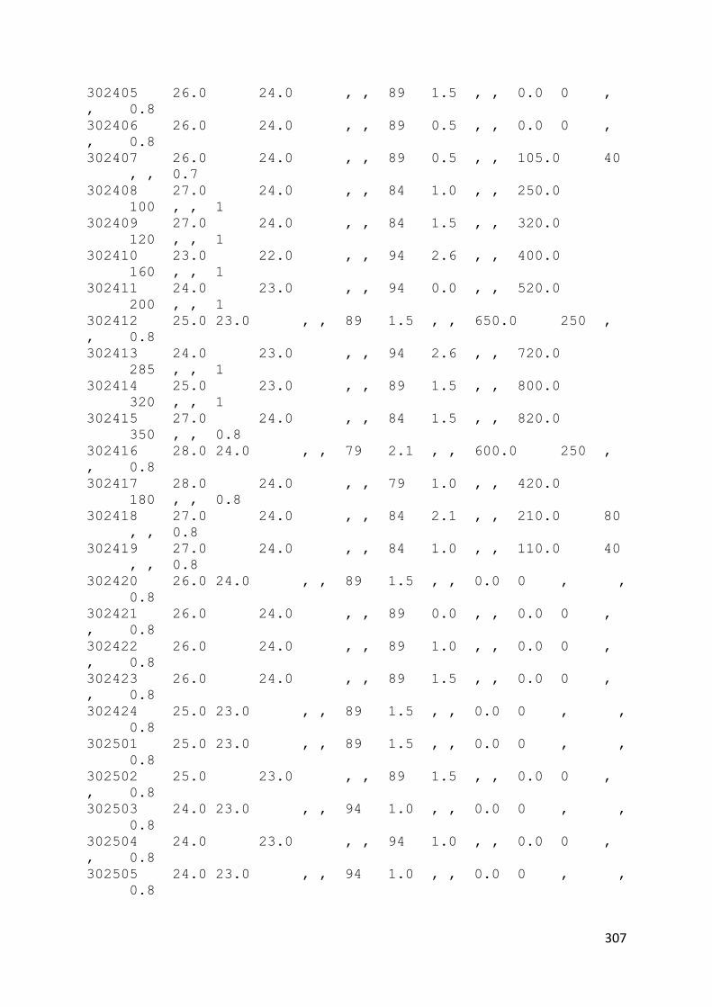
307
302405 26.0 24.0 , , 89 1.5 , , 0.0 0 ,
, 0.8
302406 26.0 24.0 , , 89 0.5 , , 0.0 0 ,
, 0.8
302407 26.0 24.0 , , 89 0.5 , , 105.0 40
, , 0.7
302408 27.0 24.0 , , 84 1.0 , , 250.0
100 , , 1
302409 27.0 24.0 , , 84 1.5 , , 320.0
120 , , 1
302410 23.0 22.0 , , 94 2.6 , , 400.0
160 , , 1
302411 24.0 23.0 , , 94 0.0 , , 520.0
200 , , 1
302412 25.0 23.0 , , 89 1.5 , , 650.0 250 ,
, 0.8
302413 24.0 23.0 , , 94 2.6 , , 720.0
285 , , 1
302414 25.0 23.0 , , 89 1.5 , , 800.0
320 , , 1
302415 27.0 24.0 , , 84 1.5 , , 820.0
350 , , 0.8
302416 28.0 24.0 , , 79 2.1 , , 600.0 250 ,
, 0.8
302417 28.0 24.0 , , 79 1.0 , , 420.0
180 , , 0.8
302418 27.0 24.0 , , 84 2.1 , , 210.0 80
, , 0.8
302419 27.0 24.0 , , 84 1.0 , , 110.0 40
, , 0.8
302420 26.0 24.0 , , 89 1.5 , , 0.0 0 , ,
0.8
302421 26.0 24.0 , , 89 0.0 , , 0.0 0 ,
, 0.8
302422 26.0 24.0 , , 89 1.0 , , 0.0 0 ,
, 0.8
302423 26.0 24.0 , , 89 1.5 , , 0.0 0 ,
, 0.8
302424 25.0 23.0 , , 89 1.5 , , 0.0 0 , ,
0.8
302501 25.0 23.0 , , 89 1.5 , , 0.0 0 , ,
0.8
302502 25.0 23.0 , , 89 1.5 , , 0.0 0 ,
, 0.8
302503 24.0 23.0 , , 94 1.0 , , 0.0 0 , ,
0.8
302504 24.0 23.0 , , 94 1.0 , , 0.0 0 ,
, 0.8
302505 24.0 23.0 , , 94 1.0 , , 0.0 0 , ,
0.8

308
302506 24.0 23.0 , , 94 0.5 , , 0.0 0 ,
, 0.8
302507 24.0 23.0 , , 94 1.0 , , 105.0 40 ,
, 0.8
302508 24.0 23.0 , , 94 1.5 , , 250.0
100 , , 0.8
302509 26.0 23.0 , , 83 1.0 , , 320.0
120 , , 0.8
302510 28.0 24.0 , , 79 1.5 , , 400.0
160 , , 0.3
302511 29.0 24.0 , , 74 1.0 , , 520.0
200 , , 0.8
302512 31.0 24.0 , , 66 2.1 , , 650.0
250 , , 0.8
302513 30.0 25.0 , , 74 5.1 , , 720.0
285 , , 0.8
302514 28.0 24.0 , , 79 4.1 , , 800.0
320 , , 1
302515 27.0 24.0 , , 84 3.6 , , 820.0
350 , , 1
302516 26.0 24.0 , , 89 2.1 , , 600.0
250 , , 0.8
302517 30.0 24.0 , , 70 3.1 , , 420.0 180 ,
, 0.8
302518 30.0 24.0 , , 70 2.6 , , 210.0 80
, , 0.8
302519 29.0 25.0 , , 79 1.5 , , 110.0 40
, , 0.8
302520 28.0 24.0 , , 79 2.1 , , 0.0 0 ,
, 0.8
302521 26.0 25.0 , , 94 2.6 , , 0.0 0 , ,
0.8
302522 27.0 24.0 , , 84 1.5 , , 0.0 0 ,
, 0.8
302523 26.0 23.0 , , 83 1.0 , , 0.0 0 ,
, 0.8
302524 25.0 22.0 , , 83 1.0 , , 0.0 0 ,
, 0.8
302601 25.0 23.0 , , 89 1.0 , , 0.0 0 ,
, 0.8
302602 25.0 23.0 , , 89 0.0 , , 0.0 0 ,
, 0.8
302603 25.0 23.0 , , 89 0.0 , , 0.0 0 , ,
0.8
302604 24.0 23.0 , , 94 0.0 , , 0.0 0 ,
, 0.8
302605 24.0 23.0 , , 94 0.0 , , 0.0 0 ,
, 0.8
302606 24.0 23.0 , , 94 0.0 , , 0.0 0 ,
, 0.8

309
302607 24.0 23.0 , , 94 1.0 , , 105.0 40
, , 0.8
302608 25.0 24.0 , , 94 0.5 , , 250.0 100 ,
, 0.8
302609 27.0 24.0 , , 84 0.0 , , 320.0
120 , , 0.8
302610 29.0 24.0 , , 74 0.5 , , 400.0
160 , , 0.8
302611 30.0 24.0 , , 70 2.1 , , 520.0
200 , , 0.8
302612 31.0 24.0 , , 66 0.5 , , 650.0
250 , , 0.8
302613 29.0 25.0 , , 79 3.6 , , 720.0 285 ,
, 0.8
302614 30.0 26.0 , , 79 4.1 , , 800.0
320 , , 0.8
302615 31.0 25.0 , , 70 1.0 , , 820.0
350 , , 1
302616 30.0 25.0 , , 74 3.6 , , 600.0 250 ,
, 0.8
302617 30.0 25.0 , , 74 3.1 , , 420.0
180 , , 0.8
302618 27.0 21.0 , , 70 3.6 , , 210.0 80
, , 0.8
302619 26.0 23.0 , , 83 2.6 , , 110.0 40
, , 0.8
302620 26.0 23.0 , , 83 2.1 , , 0.0 0 ,
, 0.8
302621 26.0 23.0 , , 83 1.5 , , 0.0 0 ,
, 0.8
302622 25.0 23.0 , , 89 2.1 , , 0.0 0 , ,
0.8
302623 26.0 24.0 , , 89 0.0 , , 0.0 0 ,
, 0.8
302624 26.0 24.0 , , 89 0.5 , , 0.0 0 ,
, 0.8
302701 25.0 23.0 , , 89 2.6 , , 0.0 0 , ,
0.8
302702 24.0 23.0 , , 94 1.5 , , 0.0 0 ,
, 0.8
302703 24.0 23.0 , , 94 1.5 , , 0.0 0
, , 0.8
302704 24.0 23.0 , , 94 0.5 , , 0.0 0 , ,
0.8
302705 24.0 23.0 , , 94 0.5 , , 0.0 0 ,
, 0.8
302706 24.0 23.0 , , 94 1.5 , , 0.0 0 ,
, 0.8
302707 25.0 23.0 , , 89 1.5 , , 105.0 40 ,
, 0.8
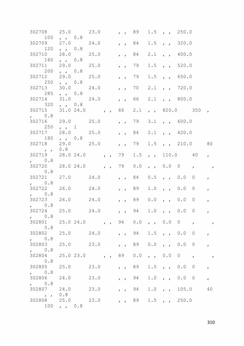
310
302708 25.0 23.0 , , 89 1.5 , , 250.0
100 , , 0.8
302709 27.0 24.0 , , 84 1.5 , , 320.0
120 , , 0.8
302710 28.0 25.0 , , 84 2.1 , , 400.0
160 , , 0.8
302711 29.0 25.0 , , 79 1.5 , , 520.0
200 , , 0.8
302712 29.0 25.0 , , 79 1.5 , , 650.0
250 , , 0.8
302713 30.0 24.0 , , 70 2.1 , , 720.0
285 , , 0.8
302714 31.0 24.0 , , 66 2.1 , , 800.0
320 , , 0.8
302715 31.0 24.0 , , 66 2.1 , , 820.0 350 ,
, 0.8
302716 29.0 25.0 , , 79 3.1 , , 600.0
250 , , 1
302717 28.0 25.0 , , 84 2.1 , , 420.0
180 , , 0.8
302718 29.0 25.0 , , 79 1.5 , , 210.0 80
, , 0.8
302719 28.0 24.0 , , 79 1.5 , , 110.0 40 ,
, 0.8
302720 28.0 24.0 , , 79 0.0 , , 0.0 0 , ,
0.8
302721 27.0 24.0 , , 84 0.5 , , 0.0 0 ,
, 0.8
302722 26.0 24.0 , , 89 1.0 , , 0.0 0 ,
, 0.8
302723 26.0 24.0 , , 89 0.0 , , 0.0 0 ,
, 0.8
302724 25.0 24.0 , , 94 1.0 , , 0.0 0 ,
, 0.8
302801 25.0 24.0 , , 94 0.0 , , 0.0 0 , ,
0.8
302802 25.0 24.0 , , 94 1.5 , , 0.0 0 ,
, 0.8
302803 25.0 23.0 , , 89 0.0 , , 0.0 0 ,
, 0.8
302804 25.0 23.0 , , 89 0.0 , , 0.0 0 , ,
0.8
302805 25.0 23.0 , , 89 1.5 , , 0.0 0 ,
, 0.8
302806 24.0 23.0 , , 94 1.0 , , 0.0 0 ,
, 0.8
302807 24.0 23.0 , , 94 1.0 , , 105.0 40
, , 0.8
302808 25.0 23.0 , , 89 1.5 , , 250.0
100 , , 0.8

311
302809 27.0 23.0 , , 79 3.1 , , 320.0 120 ,
, 0.8
302810 27.0 23.0 , , 79 2.6 , , 400.0
160 , , 0.8
302811 29.0 24.0 , , 74 2.1 , , 520.0
200 , , 0.8
302812 31.0 23.0 , , 62 1.5 , , 650.0
250 , , 0.8
302813 31.0 24.0 , , 66 0.5 , , 720.0
285 , , 0.8
302814 30.0 24.0 , , 70 2.1 , , 800.0
320 , , 1
302815 32.0 22.0 , , 55 2.6 , , 820.0 350 ,
, 0.8
302816 32.0 23.0 , , 59 3.1 , , 600.0
250 , , 0.8
302817 31.0 23.0 , , 62 3.6 , , 420.0
180 , , 0.8
302818 31.0 22.0 , , 58 2.6 , , 210.0 80
, , 0.8
302819 30.0 22.0 , , 62 2.1 , , 110.0 40
, , 0.8
302820 28.0 23.0 , , 74 2.6 , , 0.0 0 ,
, 0.8
302821 27.0 22.0 , , 74 3.6 , , 0.0 0 ,
, 0.8
302822 26.0 23.0 , , 83 2.6 , , 0.0 0 ,
, 0.8
302823 25.0 23.0 , , 89 2.6 , , 0.0 0 ,
, 0.8
302824 25.0 23.0 , , 89 1.5 , , 0.0 0 ,
, 0.8
302901 25.0 23.0 , , 89 2.1 , , 0.0 0 ,
, 0.8
302902 25.0 23.0 , , 89 1.0 , , 0.0 0 ,
, 0.8
302903 25.0 23.0 , , 89 1.5 , , 0.0 0 ,
, 0.8
302904 25.0 23.0 , , 89 1.0 , , 0.0 0 , ,
0.8
302905 24.0 23.0 , , 94 1.5 , , 0.0 0 ,
, 0.8
302906 24.0 23.0 , , 94 0.5 , , 0.0 0 ,
, 0.8
302907 24.0 23.0 , , 94 0.5 , , 105.0 40
, , 0.8
302908 24.0 23.0 , , 94 2.1 , , 250.0
100 , , 0.8
302909 26.0 23.0 , , 83 2.6 , , 320.0
120 , , 0.8
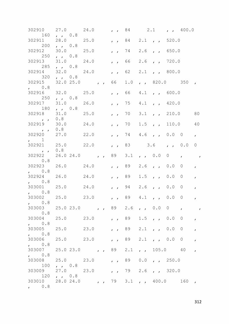
312
302910 27.0 24.0 , , 84 2.1 , , 400.0
160 , , 0.8
302911 28.0 25.0 , , 84 2.1 , , 520.0
200 , , 0.8
302912 30.0 25.0 , , 74 2.6 , , 650.0
250 , , 0.8
302913 31.0 24.0 , , 66 2.6 , , 720.0
285 , , 0.8
302914 32.0 24.0 , , 62 2.1 , , 800.0
320 , , 0.8
302915 32.0 25.0 , , 66 1.0 , , 820.0 350 ,
, 0.8
302916 32.0 25.0 , , 66 4.1 , , 600.0
250 , , 0.8
302917 31.0 26.0 , , 75 4.1 , , 420.0
180 , , 0.8
302918 31.0 25.0 , , 70 3.1 , , 210.0 80
, , 0.8
302919 30.0 24.0 , , 70 1.5 , , 110.0 40
, , 0.8
302920 27.0 22.0 , , 74 4.6 , , 0.0 0 ,
, 1
302921 25.0 22.0 , , 83 3.6 , , 0.0 0
, , 0.8
302922 26.0 24.0 , , 89 3.1 , , 0.0 0 , ,
0.8
302923 26.0 24.0 , , 89 2.6 , , 0.0 0 ,
, 0.8
302924 26.0 24.0 , , 89 1.5 , , 0.0 0 ,
, 0.8
303001 25.0 24.0 , , 94 2.6 , , 0.0 0 ,
, 0.8
303002 25.0 23.0 , , 89 4.1 , , 0.0 0 ,
, 0.8
303003 25.0 23.0 , , 89 2.6 , , 0.0 0 , ,
0.8
303004 25.0 23.0 , , 89 1.5 , , 0.0 0 ,
, 0.8
303005 25.0 23.0 , , 89 2.1 , , 0.0 0 ,
, 0.8
303006 25.0 23.0 , , 89 2.1 , , 0.0 0 ,
, 0.8
303007 25.0 23.0 , , 89 2.1 , , 105.0 40 ,
, 0.8
303008 25.0 23.0 , , 89 0.0 , , 250.0
100 , , 0.8
303009 27.0 23.0 , , 79 2.6 , , 320.0
120 , , 0.8
303010 28.0 24.0 , , 79 3.1 , , 400.0 160 ,
, 0.8

313
303011 29.0 25.0 , , 79 4.1 , , 520.0
200 , , 0.8
303012 30.0 25.0 , , 74 4.1 , , 650.0
250 , , 0.8
303013 31.0 25.0 , , 70 4.6 , , 720.0
285 , , 0.8
303014 32.0 25.0 , , 66 4.1 , , 800.0
320 , , 0.8
303015 32.0 27.0 , , 75 4.6 , , 820.0
350 , , 0.8
303016 31.0 26.0 , , 75 3.1 , , 600.0
250 , , 0.8
303017 26.0 24.0 , , 89 2.1 , , 420.0
180 , , 1
303018 25.0 24.0 , , 94 0.0 , , 210.0 80
, , 1
303019 25.0 23.0 , , 89 0.5 , , 110.0 40
, , 1
303020 25.0 23.0 , , 89 1.0 , , 0.0 0 ,
, 1
303021 25.0 23.0 , , 89 1.5 , , 0.0 0 ,
, 1
303022 25.0 24.0 , , 94 1.5 , , 0.0 0 ,
, 0.3
303023 25.0 24.0 , , 94 0.0 , , 0.0 0 ,
, 0.8
303024 25.0 24.0 , , 94 1.5 , , 0.0 0 , ,
0.8
303101 25.0 24.0 , , 94 1.0 , , 0.0 0 ,
, 0.8
303102 24.0 23.0 , , 94 1.0 , , 0.0 0 ,
, 0.8
303103 24.0 24.0 , , 100 1.5 , , 0.0 0 ,
, 0.8
303104 24.0 24.0 , , 100 1.5 , , 0.0 0 ,
, 0.8
303105 24.0 23.0 , , 94 1.0 , , 0.0 0
, , 0.8
303106 24.0 23.0 , , 94 1.0 , , 0.0 0 ,
, 0.8
303107 24.0 23.0 , , 94 0.5 , , 105.0 40
, , 0.8
303108 24.0 24.0 , , 100 0.5 , , 250.0
100 , , 0.8
303109 25.0 24.0 , , 94 0.0 , , 320.0
120 , , 0.8
303110 27.0 25.0 , , 89 1.0 , , 400.0
160 , , 0.8
303111 28.0 25.0 , , 84 1.5 , , 520.0
200 , , 0.8

314
303112 30.0 24.0 , , 70 2.6 , , 650.0
250 , , 0.8
303113 30.0 24.0 , , 70 2.1 , , 720.0
285 , , 0.8
303114 31.0 23.0 , , 62 1.5 , , 800.0
320 , , 0.8
303115 32.0 23.0 , , 59 3.1 , , 820.0
350 , , 0.8
303116 32.0 25.0 , , 66 1.5 , , 600.0
250 , , 0.8
303117 32.0 25.0 , , 66 1.5 , , 420.0
180 , , 0.8
303118 30.0 24.0 , , 70 3.1 , , 210.0 80
, , 0.8
303119 29.0 24.0 , , 74 2.1 , , 110.0 40 ,
, 0.8
303120 29.0 24.0 , , 74 2.1 , , 0.0 0 ,
, 0.8
303121 28.0 24.0 , , 79 0.0 , , 0.0 0 ,
, 0.8
303012 27.0 24.0 , , 84 2.1 , , 0.0 0 ,
, 0.8
303123 26.0 23.0 , , 83 1.5 , , 0.0 0 ,
, 0.8

315
HTB2 – BUILDING FILE : PITCHED ROOF
!PROJECTID PITCHED ROOF 45degree
!LOCATION = 101.7 2.9
!DEFINE SPACE = '1 -ROOF Space'
!VOLUME = 213.33
!END
!MATERIALS FILE = 'STDMAT.LBY'
!MATERIAL USER = 'PITCHMATS.LBY'
!CONSTRUCTION FILE = 'PITCH.CON'
!LAYOUT FILE = 'PITCH.LAY'

316
HTB2 – CONSTRUCTION FILE: PITCHED
* construction definition file for mosque
* uses user defined materials list
!MATERIALS USER FILE = 'JAMEKMATS.LBY'
* and standard library
!CONSTRUCTION '1 external wall'
!TYPE OPAQUE
!PARTS
* part material width slices
* : : : :
_ 1 = 34 0.016 0 * plaster
_ 2 = 1 0.105 0 * brick
_ 3 = 34 0.016 0 * plaster
}
!END
!CONSTRUCTION '2 single glazing'
!TYPE TRANSPARENT
!PARTS
* part material width slices absorp
* : : : :
_ 1 = 65 0.006 0 1.00 * window
glass
}
!END
!CONSTRUCTION '3 solid ground floor '
!TYPE OPAQUE
!PARTS
* part material width slices
* : : : :
_ 1 = @10 0.015 0 * carpet
_ 2 = @11 0.100 0 * concrete
_ 3 = @12 1.600 0 * earth
}
!END
!CONSTRUCTION '4 internal ceiling'
!TYPE OPAQUE
!PARTS
* part material width slices
* : : : :
_ 1 = @5 0.100 0 * insulation
quilt
_ 2 = @4 0.010 0 *
plasterboard

317
}
!END
!CONSTRUCTION '5 roof'
!TYPE OPAQUE
!PARTS
* part material width slices
* : : : :
_ 1 = @8 0.010 0 * tiles
}
!END
!CONSTRUCTION '6 internal partition'
!TYPE OPAQUE
!PARTS
* part material width slices
* : : : :
_ 1 = @3 0.016 0 * plaster
_ 2 = @2 0.105 0 * brick
(inner)
_ 3 = @3 0.016 0 * plaster
}
!END
!CONSTRUCTION '7 timber grille wall'
!TYPE OPAQUE
!PARTS
* part material width slices
* : : : :
_ 1 = 49 0.190 0 * oak
(radial)
}
!END
!CONSTRUCTION '8 concrete roofing'
!TYPE OPAQUE
!PARTS
* part material width slices
* : : : :
_ 1 = 10 0.300 0 * CONCRETE (HEAVY
MIX)
}
!END
!CONSTRUCTION '9 ROOF1'
!TYPE OPAQUE
!PARTS
* part material width slices
* : : : :
_ 1 = 30 0.013 0 * tiles

318
_ 2 = 58 0.085 0 * styrofoam
_ 3 = 36 0.013 0 * p'board
}
!END
!CONSTRUCTION '10 solid ground floor with tiles'
!TYPE OPAQUE
!PARTS
* part material width slices
* : : : :
_1 = 21 0.030 0 * tiles
_2 = @11 0.100 0 * concrete
_3 = @12 1.600 0 * earth
}
!END
!CONSTRUCTION '11 opening'
!TYPE TRANSPARENT
!PARTS
* part material width slices absorp
* : : : :
_1 = @13 0.015 0 1.0 * opening
}
!END
* window type definitions
!WINDOW = '6MMFLOAT'
!TRANSMISSION =
0.64 , 0.80 , 0.80 , 0.80, 0.80, 0.78, 0.75, 0.71, 0.60,
0.36, 0.0
!ABSORPTION =
0.134 , 0.12, 0.12, 0.12, 0.12, 0.14, 0.14, 0.14, 0.14, 0.15,
0.15
!END
!WINDOW = 'OPENING'
!TRANSMISSION =
0.50, 0.50, 0.50, 0.50, 0.50, 0.50, 0.50, 0.50, 0.50, 0.50,
0.0
!ABSORPTION =
0.01, 0.01, 0.01, 0.01, 0.01, 0.01, 0.01, 0.01, 0.01, 0.01,
0.0
!END
_

319
HTB2 – LAYOUT FILE : PITCHED
!ELEMENT = '1 south roof'
!CONSTRUCTION = 9
!AREA = 22.6
!ORIENTATION = 67.0
!TILT = 45.0
!GROUND REFL = 0.2
!SPACE TO FIRST = 0
!SPACE TO LAST = 1
!CLASS = 1
!END
!ELEMENT = '2 east roof'
!CONSTRUCTION = 9
!AREA = 22.6
!ORIENTATION = 157.0
!TILT = 45.0
!GROUND REFL = 0.2
!SPACE TO FIRST = 0
!SPACE TO LAST = 1
!CLASS = 1
!END
!ELEMENT = '3 north roof'
!CONSTRUCTION = 9
!AREA = 22.6
!ORIENTATION = 247.0
!TILT = 45.0
!GROUND REFL = 0.2
!SPACE TO FIRST = 0
!SPACE TO LAST = 1
!CLASS = 1
!END
!ELEMENT = '4 south roof'
!CONSTRUCTION = 9
!AREA = 22.6
!ORIENTATION = 337.0
!TILT = 45.0
!GROUND REFL = 0.2
!SPACE TO FIRST = 0
!SPACE TO LAST = 1
!CLASS = 1
!END
!ELEMENT = '5 south wall'
!CONSTRUCTION = 1
!AREA = 8.0
!ORIENTATION = 67.0
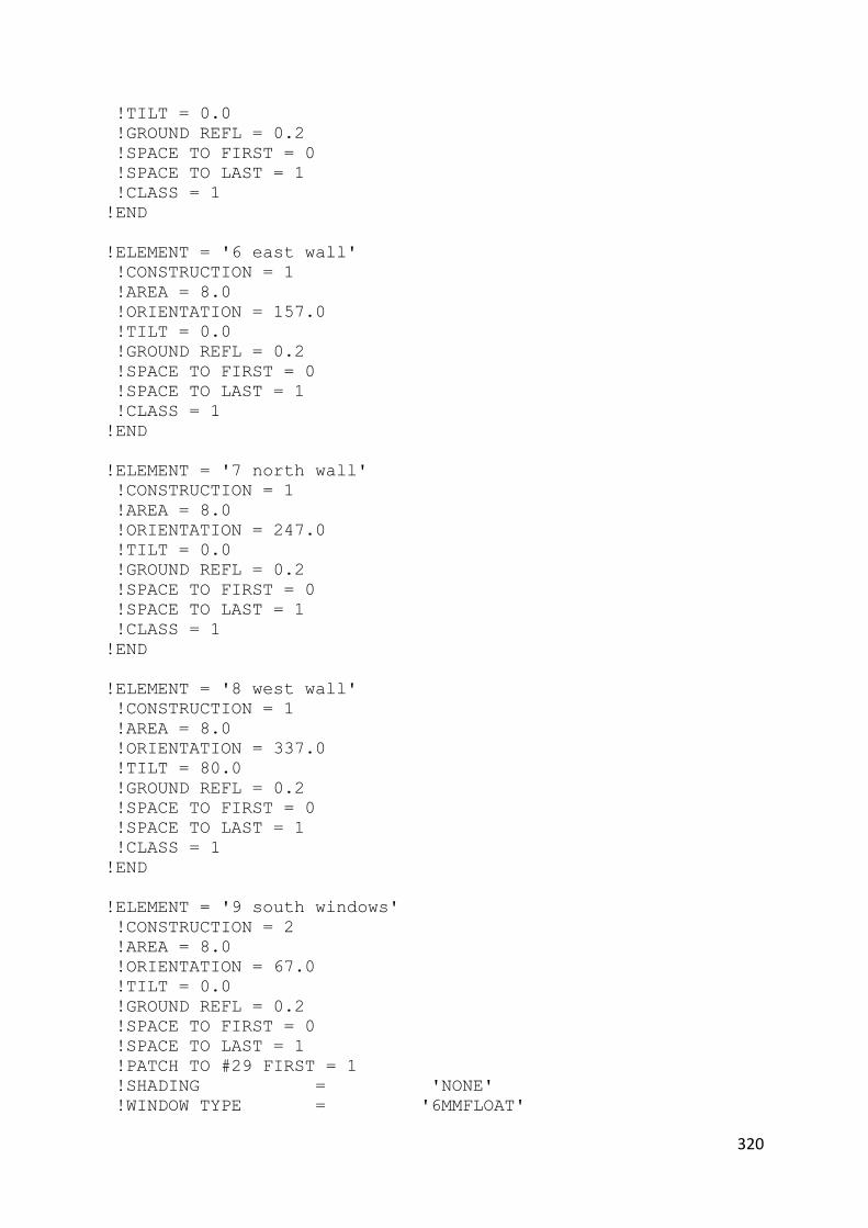
320
!TILT = 0.0
!GROUND REFL = 0.2
!SPACE TO FIRST = 0
!SPACE TO LAST = 1
!CLASS = 1
!END
!ELEMENT = '6 east wall'
!CONSTRUCTION = 1
!AREA = 8.0
!ORIENTATION = 157.0
!TILT = 0.0
!GROUND REFL = 0.2
!SPACE TO FIRST = 0
!SPACE TO LAST = 1
!CLASS = 1
!END
!ELEMENT = '7 north wall'
!CONSTRUCTION = 1
!AREA = 8.0
!ORIENTATION = 247.0
!TILT = 0.0
!GROUND REFL = 0.2
!SPACE TO FIRST = 0
!SPACE TO LAST = 1
!CLASS = 1
!END
!ELEMENT = '8 west wall'
!CONSTRUCTION = 1
!AREA = 8.0
!ORIENTATION = 337.0
!TILT = 80.0
!GROUND REFL = 0.2
!SPACE TO FIRST = 0
!SPACE TO LAST = 1
!CLASS = 1
!END
!ELEMENT = '9 south windows'
!CONSTRUCTION = 2
!AREA = 8.0
!ORIENTATION = 67.0
!TILT = 0.0
!GROUND REFL = 0.2
!SPACE TO FIRST = 0
!SPACE TO LAST = 1
!PATCH TO #29 FIRST = 1
!SHADING = 'NONE'
!WINDOW TYPE = '6MMFLOAT'

321
!CLASS = 2
!END
!ELEMENT = '10 east windows'
!CONSTRUCTION = 2
!AREA = 8.0
!ORIENTATION = 157.0
!TILT = 0.0
!GROUND REFL = 0.2
!SPACE TO FIRST = 0
!SPACE TO LAST = 1
!PATCH TO #29 FIRST = 1
!SHADING = 'NONE'
!WINDOW TYPE = '6MMFLOAT'
!CLASS = 2
!END
!ELEMENT = '11 north windows'
!CONSTRUCTION = 2
!AREA = 8.0
!ORIENTATION = 247.0
!TILT = 0.0
!GROUND REFL = 0.2
!SPACE TO FIRST = 0
!SPACE TO LAST = 1
!PATCH TO #29 FIRST = 1
!SHADING = 'NONE'
!WINDOW TYPE = '6MMFLOAT'
!CLASS = 2
!END
!ELEMENT = '12 west windows'
!CONSTRUCTION = 2
!AREA = 8.0
!ORIENTATION = 337.0
!TILT = 0.0
!GROUND REFL = 0.2
!SPACE TO FIRST = 0
!SPACE TO LAST = 1
!PATCH TO #29 FIRST = 1
!SHADING = 'NONE'
!WINDOW TYPE = '6MMFLOAT'
!CLASS = 2
!END

322
TOP LEVEL FILE
* Top top Level file for pitched Mosque, Seremban, Standard
!RUNID PITCH Mosque Seremban, standard run at 45 degree pitch
* configure model...
!ENABLE METEOROLOGICAL
!ENABLE FABRIC
!ENABLE RADTRAN STAR
!ENABLE SOLAR
* calc ground temp
!ENABLE GROUND TEMP CALCS
!SET GROUND FACTOR = 0.001
* set up run parameters
!SET TIMESTEP = 120.0
!SET RUNLENGTH = 010,00
* allow 1st 3 days for runup
!SET BST = 01/13 31/13
!SET DATE = 01/03/2009
* chose output files and data
!OUTPUT INFO = 'PITCH.INF'
!OUTPUT BLOCK FILE = 'PITCH.BLK'
!ENABLE BLOCK REPORT
!ENABLE BLOCK OUTPUT
* connect to further files
!DEFINE BUILDING FILE = 'PITCH.BLD'
!DEFINE METEOR FILE = 'MARCH09.MET'

323
HTB2 – VENTILATION FILE : PITCHED
1 * dome mosque
*********** * simple ACRs, constant air infiltration
1 * dome roof space
1.70 , 0.0 , 0.0 * INFILTRATION RATE INFIL, LOW, HIGH
25.0 * VENT STAT SETTING
-----------
0
_

324
TOP LEVEL FILE
* Top top Level file for Jamek Mosque, Seremban, Standard
!RUNID PITCH Mosque Seremban, standard run at 45 degree pitch
* configure model...
!ENABLE METEOROLOGICAL
!ENABLE FABRIC
!ENABLE RADTRAN STAR
!ENABLE SOLAR
!ENABLE WATER
!ENABLE VENTILATION
* calc ground temp
!ENABLE GROUND TEMP CALCS
!SET GROUND FACTOR = 0.001
* set up run parameters
!SET TIMESTEP = 120.0
!SET RUNLENGTH = 010,00
* allow 1st 3 days for runup
!SET BST = 01/13 31/13
!SET DATE = 01/03/2009
* chose output files and data
!OUTPUT INFO = 'PITCH0.INF'
!OUTPUT BLOCK FILE = 'PITCH0.BLK'
!ENABLE BLOCK REPORT
!ENABLE BLOCK OUTPUT
* connect to further files
!DEFINE BUILDING FILE = 'PITCH.BLD'
!DEFINE METEOR FILE = 'MARCH09.MET'
!DEFINE VENTILATION = 'PITCH.VNT'

325
BUILDING FILE
!PROJECTID PITCHED ROOF 60degree
!LOCATION = 101.7 2.9
!DEFINE SPACE = '1 -ROOF Space'
!VOLUME = 262.36
!END
!MATERIALS FILE = 'STDMAT.LBY'
!MATERIAL USER = 'PITCHMATS.LBY'
!CONSTRUCTION FILE = 'PITCH.CON'
!LAYOUT FILE = 'PITCH1.LAY'
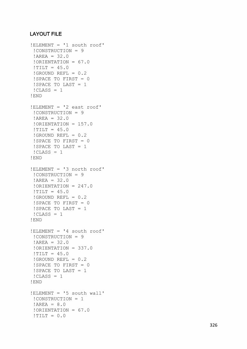
326
LAYOUT FILE
!ELEMENT = '1 south roof'
!CONSTRUCTION = 9
!AREA = 32.0
!ORIENTATION = 67.0
!TILT = 45.0
!GROUND REFL = 0.2
!SPACE TO FIRST = 0
!SPACE TO LAST = 1
!CLASS = 1
!END
!ELEMENT = '2 east roof'
!CONSTRUCTION = 9
!AREA = 32.0
!ORIENTATION = 157.0
!TILT = 45.0
!GROUND REFL = 0.2
!SPACE TO FIRST = 0
!SPACE TO LAST = 1
!CLASS = 1
!END
!ELEMENT = '3 north roof'
!CONSTRUCTION = 9
!AREA = 32.0
!ORIENTATION = 247.0
!TILT = 45.0
!GROUND REFL = 0.2
!SPACE TO FIRST = 0
!SPACE TO LAST = 1
!CLASS = 1
!END
!ELEMENT = '4 south roof'
!CONSTRUCTION = 9
!AREA = 32.0
!ORIENTATION = 337.0
!TILT = 45.0
!GROUND REFL = 0.2
!SPACE TO FIRST = 0
!SPACE TO LAST = 1
!CLASS = 1
!END
!ELEMENT = '5 south wall'
!CONSTRUCTION = 1
!AREA = 8.0
!ORIENTATION = 67.0
!TILT = 0.0

327
!GROUND REFL = 0.2
!SPACE TO FIRST = 0
!SPACE TO LAST = 1
!CLASS = 1
!END
!ELEMENT = '6 east wall'
!CONSTRUCTION = 1
!AREA = 8.0
!ORIENTATION = 157.0
!TILT = 0.0
!GROUND REFL = 0.2
!SPACE TO FIRST = 0
!SPACE TO LAST = 1
!CLASS = 1
!END
!ELEMENT = '7 north wall'
!CONSTRUCTION = 1
!AREA = 8.0
!ORIENTATION = 247.0
!TILT = 0.0
!GROUND REFL = 0.2
!SPACE TO FIRST = 0
!SPACE TO LAST = 1
!CLASS = 1
!END
!ELEMENT = '8 west wall'
!CONSTRUCTION = 1
!AREA = 8.0
!ORIENTATION = 337.0
!TILT = 80.0
!GROUND REFL = 0.2
!SPACE TO FIRST = 0
!SPACE TO LAST = 1
!CLASS = 1
!END
!ELEMENT = '9 south windows'
!CONSTRUCTION = 2
!AREA = 8.0
!ORIENTATION = 67.0
!TILT = 0.0
!GROUND REFL = 0.2
!SPACE TO FIRST = 0
!SPACE TO LAST = 1
!PATCH TO #29 FIRST = 1
!SHADING = 'NONE'
!WINDOW TYPE = '6MMFLOAT'
!CLASS = 2
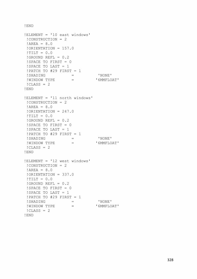
328
!END
!ELEMENT = '10 east windows'
!CONSTRUCTION = 2
!AREA = 8.0
!ORIENTATION = 157.0
!TILT = 0.0
!GROUND REFL = 0.2
!SPACE TO FIRST = 0
!SPACE TO LAST = 1
!PATCH TO #29 FIRST = 1
!SHADING = 'NONE'
!WINDOW TYPE = '6MMFLOAT'
!CLASS = 2
!END
!ELEMENT = '11 north windows'
!CONSTRUCTION = 2
!AREA = 8.0
!ORIENTATION = 247.0
!TILT = 0.0
!GROUND REFL = 0.2
!SPACE TO FIRST = 0
!SPACE TO LAST = 1
!PATCH TO #29 FIRST = 1
!SHADING = 'NONE'
!WINDOW TYPE = '6MMFLOAT'
!CLASS = 2
!END
!ELEMENT = '12 west windows'
!CONSTRUCTION = 2
!AREA = 8.0
!ORIENTATION = 337.0
!TILT = 0.0
!GROUND REFL = 0.2
!SPACE TO FIRST = 0
!SPACE TO LAST = 1
!PATCH TO #29 FIRST = 1
!SHADING = 'NONE'
!WINDOW TYPE = '6MMFLOAT'
!CLASS = 2
!END

329
TOP FILE
* Top top Level file for Jamek Mosque, Seremban, Standard
!RUNID PITCH Mosque Seremban, standard run AT 60 DEGREE PITCH
* configure model...
!ENABLE METEOROLOGICAL
!ENABLE FABRIC
!ENABLE RADTRAN STAR
!ENABLE SOLAR
!ENABLE WATER
* calc ground temp
!ENABLE GROUND TEMP CALCS
!SET GROUND FACTOR = 0.001
* set up run parameters
!SET TIMESTEP = 120.0
!SET RUNLENGTH = 010,00
* allow 1st 3 days for runup
!SET BST = 01/13 31/13
!SET DATE = 01/03/2009
* chose output files and data
!OUTPUT INFO = 'PITCH1.INF'
!OUTPUT BLOCK FILE = 'PITCH1.BLK'
!ENABLE BLOCK REPORT
!ENABLE BLOCK OUTPUT
* connect to further files
!DEFINE BUILDING FILE = 'PITCH1.BLD'
!DEFINE METEOR FILE = 'MARCH09.MET'

330
BUILDING FILE !PROJECTID PITCHED ROOF 30degree
!LOCATION = 101.7 2.9
!DEFINE SPACE = '1 -ROOF Space'
!VOLUME = 885.6
!END
!MATERIALS FILE = 'STDMAT.LBY'
!MATERIAL USER = 'PITCHMATS.LBY'
!CONSTRUCTION FILE = 'PITCH.CON'
!LAYOUT FILE = 'PITCH1ONLY.LAY'

331
LAYOUT FILE
!ELEMENT = '1 south top pitch roof1'
!CONSTRUCTION = 9
!AREA = 93.6
!ORIENTATION = 67.0
!TILT = 60.0
!GROUND REFL = 0.2
!SPACE TO FIRST = 0
!SPACE TO LAST = 1
!END
!ELEMENT = '2 east top pitch roof1'
!CONSTRUCTION = 9
!AREA = 93.6
!ORIENTATION = 157.0
!TILT = 60.0
!GROUND REFL = 0.2
!SPACE TO FIRST = 0
!SPACE TO LAST = 1
!END
!ELEMENT = '3 west top pitch roof1'
!CONSTRUCTION = 9
!AREA = 93.6
!ORIENTATION = 337.0
!TILT = 60.0
!GROUND REFL = 0.2
!SPACE TO FIRST = 0
!SPACE TO LAST = 1
!END
!ELEMENT = '4 north top pitch roof1'
!CONSTRUCTION = 9
!AREA = 93.6
!ORIENTATION = 247.0
!TILT = 60.0
!GROUND REFL = 0.2
!SPACE TO FIRST = 0
!SPACE TO LAST = 1
!END
!ELEMENT = '113 south wall'
!CONSTRUCTION = 1
!AREA = 8.0
!ORIENTATION = 67.0
!TILT = 0.0
!GROUND REFL = 0.2
!SPACE TO FIRST = 0
!SPACE TO LAST = 1

332
!CLASS = 1
!END
!ELEMENT = '114 east wall'
!CONSTRUCTION = 1
!AREA = 8.0
!ORIENTATION = 157.0
!TILT = 0.0
!GROUND REFL = 0.2
!SPACE TO FIRST = 0
!SPACE TO LAST = 1
!CLASS = 1
!END
!ELEMENT = '115 north wall'
!CONSTRUCTION = 1
!AREA = 8.0
!ORIENTATION = 247.0
!TILT = 0.0
!GROUND REFL = 0.2
!SPACE TO FIRST = 0
!SPACE TO LAST = 1
!CLASS = 1
!END
!ELEMENT = '116 west wall'
!CONSTRUCTION = 1
!AREA = 8.0
!ORIENTATION = 337.0
!TILT = 80.0
!GROUND REFL = 0.2
!SPACE TO FIRST = 0
!SPACE TO LAST = 1
!CLASS = 1
!END
!ELEMENT = '117 south windows'
!CONSTRUCTION = 2
!AREA = 10.0
!ORIENTATION = 67.0
!TILT = 0.0
!GROUND REFL = 0.2
!SPACE TO FIRST = 0
!SPACE TO LAST = 1
!PATCH TO #29 FIRST = 1
!SHADING = 'NONE'
!WINDOW TYPE = '6MMFLOAT'
!CLASS = 2
!END
!ELEMENT = '118 east windows'

333
!CONSTRUCTION = 2
!AREA = 10.0
!ORIENTATION = 157.0
!TILT = 0.0
!GROUND REFL = 0.2
!SPACE TO FIRST = 0
!SPACE TO LAST = 1
!PATCH TO #29 FIRST = 1
!SHADING = 'NONE'
!WINDOW TYPE = '6MMFLOAT'
!CLASS = 2
!END
!ELEMENT = '119 north windows'
!CONSTRUCTION = 2
!AREA = 10.0
!ORIENTATION = 247.0
!TILT = 0.0
!GROUND REFL = 0.2
!SPACE TO FIRST = 0
!SPACE TO LAST = 1
!PATCH TO #29 FIRST = 1
!SHADING = 'NONE'
!WINDOW TYPE = '6MMFLOAT'
!CLASS = 2
!END
!ELEMENT = '120 west windows'
!CONSTRUCTION = 2
!AREA = 10.0
!ORIENTATION = 337.0
!TILT = 0.0
!GROUND REFL = 0.2
!SPACE TO FIRST = 0
!SPACE TO LAST = 1
!PATCH TO #29 FIRST = 1
!SHADING = 'NONE'
!WINDOW TYPE = '6MMFLOAT'
!CLASS = 2
!END

334
TOP LEVEL FILE * Top top Level file for PITCH only, Standard
!RUNID PITCH only, standard run at 30 degree pitch
* configure model...
!ENABLE METEOROLOGICAL
!ENABLE FABRIC
!ENABLE RADTRAN STAR
!ENABLE SOLAR
!ENABLE WATER
!ENABLE VENTILATION
* calc ground temp
!ENABLE GROUND TEMP CALCS
!SET GROUND FACTOR = 0.001
* set up run parameters
!SET TIMESTEP = 120.0
!SET RUNLENGTH = 010,00
* allow 1st 3 days for runup
!SET BST = 01/13 31/13
!SET DATE = 01/03/2009
* chose output files and data
!OUTPUT INFO = 'PITCH1ONLY.INF'
!OUTPUT BLOCK FILE = 'PITCH1ONLY.BLK'
!ENABLE BLOCK REPORT
!ENABLE BLOCK OUTPUT
!ENABLE REPORT ALL
* connect to further files
!DEFINE BUILDING FILE = 'PITCH1ONLY.BLD'
!DEFINE METEOR FILE = 'MARCH09.MET'
!DEFINE VENTILATION = 'PITCH.VNT'
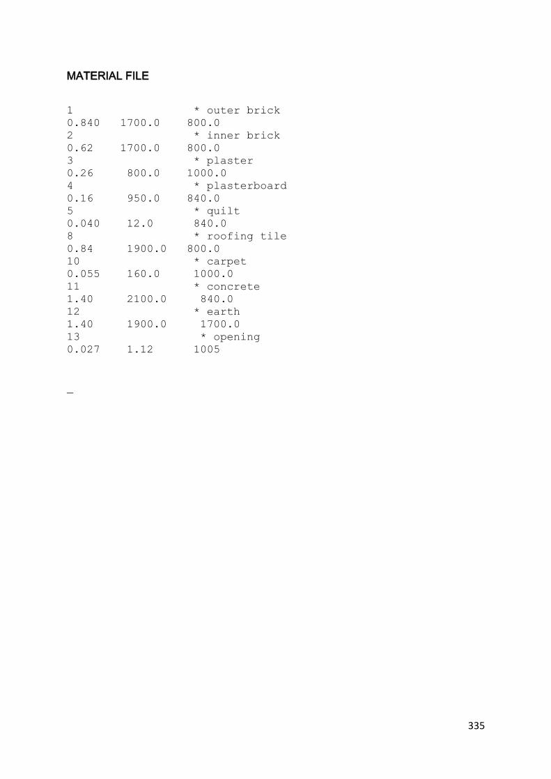
335
MATERIAL FILE
1 * outer brick
0.840 1700.0 800.0
2 * inner brick
0.62 1700.0 800.0
3 * plaster
0.26 800.0 1000.0
4 * plasterboard
0.16 950.0 840.0
5 * quilt
0.040 12.0 840.0
8 * roofing tile
0.84 1900.0 800.0
10 * carpet
0.055 160.0 1000.0
11 * concrete
1.40 2100.0 840.0
12 * earth
1.40 1900.0 1700.0
13 * opening
0.027 1.12 1005
_
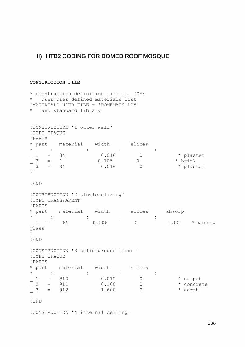
336
ll) HTB2 CODING FOR DOMED ROOF MOSQUE
CONSTRUCTION FILE
* construction definition file for DOME
* uses user defined materials list
!MATERIALS USER FILE = 'DOMEMATS.LBY'
* and standard library
!CONSTRUCTION '1 outer wall'
!TYPE OPAQUE
!PARTS
* part material width slices
* : : : :
_ 1 = 34 0.016 0 * plaster
_ 2 = 1 0.105 0 * brick
_ 3 = 34 0.016 0 * plaster
}
!END
!CONSTRUCTION '2 single glazing'
!TYPE TRANSPARENT
!PARTS
* part material width slices absorp
* : : : :
_ 1 = 65 0.006 0 1.00 * window
glass
}
!END
!CONSTRUCTION '3 solid ground floor '
!TYPE OPAQUE
!PARTS
* part material width slices
* : : : :
_ 1 = @10 0.015 0 * carpet
_ 2 = @11 0.100 0 * concrete
_ 3 = @12 1.600 0 * earth
}
!END
!CONSTRUCTION '4 internal ceiling'
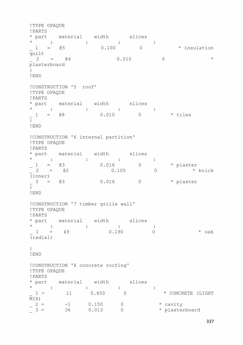
337
!TYPE OPAQUE
!PARTS
* part material width slices
* : : : :
_ 1 = @5 0.100 0 * insulation
quilt
_ 2 = @4 0.010 0 *
plasterboard
}
!END
!CONSTRUCTION '5 roof'
!TYPE OPAQUE
!PARTS
* part material width slices
* : : : :
_ 1 = @8 0.010 0 * tiles
}
!END
!CONSTRUCTION '6 internal partition'
!TYPE OPAQUE
!PARTS
* part material width slices
* : : : :
_ 1 = @3 0.016 0 * plaster
_ 2 = @2 0.105 0 * brick
(inner)
_ 3 = @3 0.016 0 * plaster
}
!END
!CONSTRUCTION '7 timber grille wall'
!TYPE OPAQUE
!PARTS
* part material width slices
* : : : :
_ 1 = 49 0.190 0 * oak
(radial)
}
!END
!CONSTRUCTION '8 concrete roofing'
!TYPE OPAQUE
!PARTS
* part material width slices
* : : : :
_ 1 = 11 0.450 0 * CONCRETE (LIGHT
MIX)
_ 2 = -1 0.150 0 * cavity
_ 3 = 36 0.013 0 * plasterboard

338
}
!END
!CONSTRUCTION '9 ROOF1'
!TYPE OPAQUE
!PARTS
* part material width slices
* : : : :
_ 1 = 30 0.013 0 * tiles
_ 2 = 58 0.085 0 * styrofoam
_ 3 = 36 0.013 0 * p'board
}
!END
!CONSTRUCTION '10 solid ground floor with tiles'
!TYPE OPAQUE
!PARTS
* part material width slices
* : : : :
_ 1 = 21 0.030 0 * tiles
_ 2 = @11 0.100 0 * concrete
_ 3 = @12 1.600 0 * earth
}
!END
!CONSTRUCTION '11 opening'
!TYPE TRANSPARENT
!PARTS
* part material width slices absorp
* : : : :
_1 = @13 0.015 0 1.0 *
opening
}
!END
!CONSTRUCTION '12 dome roofing'
!TYPE OPAQUE
!PARTS
* part material width slices
* : : : :
_ 1 = @14 0.012 0 *
polycarbonate
_ 2 = -1 0.150 0 * cavity air
_ 3 = @14 0.012 0 *
polycarbonate
}
!END
!CONSTRUCTION '13 concrete roofing'

339
!TYPE OPAQUE
!PARTS
* part material width slices
* : : : :
_ 1 = 11 0.450 0 * CONCRETE (LIGHT
MIX)
}
!END
* window type definitions
!WINDOW = '6MMFLOAT'
!TRANSMISSION =
0.64 , 0.80 , 0.80 , 0.80, 0.80, 0.78, 0.75, 0.71, 0.60,
0.36, 0.0
!ABSORPTION =
0.134 , 0.12, 0.12, 0.12, 0.12, 0.14, 0.14, 0.14, 0.14, 0.15,
0.15
!END
!WINDOW = 'OPENING'
!TRANSMISSION =
0.50, 0.50, 0.50, 0.50, 0.50, 0.50, 0.50, 0.50, 0.50, 0.50,
0.0
!ABSORPTION =
0.01, 0.01, 0.01, 0.01, 0.01, 0.01, 0.01, 0.01, 0.01, 0.01,
0.0
!END
_

340
MATERIAL FILE
1 * outer brick
0.840 1700.0 800.0
2 * inner brick
0.62 1700.0 800.0
3 * plaster
0.26 800.0 1000.0
4 * plasterboard
0.16 950.0 840.0
5 * quilt
0.040 12.0 840.0
8 * roofing tile
0.84 1900.0 800.0
10 * carpet
0.055 160.0 1000.0
11 * concrete
1.40 2100.0 840.0
12 * earth
1.40 1900.0 1700.0
13 * opening
0.024 1.12 1005
14 *polycarbonate
0.20 1200.0 1200
_

341
BUILDING FILE
!PROJECTID DOME ONLY
!LOCATION = 101.7 2.9
!DEFINE SPACE = '1 -Dome'
!VOLUME = 1851.0
!END
!MATERIALS FILE = 'STDMAT.LBY'
!MATERIAL USER = 'DOMEMATS.LBY'
!CONSTRUCTION FILE = 'DOME1.CON'
!LAYOUT FILE = 'DOMEONLY.LAY'

342
METEOROLOGICAL FILE
30101 25.0 24.0 ,, 94 1.5 ,, 0.0 0 ,, 0.8
30102 25.0 23.0 ,, 89 1.5 ,, 0.0 0 ,, 0.8
30103 25.0 23.0 ,, 89 1.0 ,, 0.0 0 ,, 0.8
30104 25.0 23.0 ,, 89 0.5 ,, 0.0 0 ,, 0.8
30105 24.0 23.0 ,, 94 1.0 ,, 0.0 0 ,, 0.8
30106 24.0 23.0 ,, 94 1.0 ,, 0.0 0 ,, 0.8
30107 24.0 23.0 ,, 94 1.5 ,, 105.0 40 ,, 0.8
30108 24.0 23.0 ,, 94 1.5 ,, 250.0 100,, 0.8
30109 26.0 24.0 ,, 89 3.1 ,, 320.0 120,, 0.8
30110 28.0 24.0 ,, 79 3.6 ,, 400.0 160,, 0.8
30111 30.0 24.0 ,, 70 4.6 ,, 480.0 200,, 0.8
30112 31.0 24.0 ,, 66 4.1 ,, 550.0 250,, 0.8
30113 32.0 24.0 ,, 62 3.1 ,, 620.0 285,, 0.8
30114 30.0 24.0 ,, 70 4.1 ,, 680.0 320,, 0.8
30115 30.0 25.0 ,, 74 2.6 ,, 720.0 350,, 0.8
30116 30.0 25.0 ,, 74 2.6 ,, 600.0 250,, 0.8
30117 32.0 24.0 ,, 62 1.5 ,, 420.0 180,, 0.8
30118 31.0 24.0 ,, 66 3.6 ,, 210.0 80,, 0.8
30119 29.0 24.0 ,, 74 2.1 ,, 110.0 40,, 1
30120 26.0 23.0 ,, 83 3.1 ,, 0.0 0,, 1
30121 26.0 24.0 ,, 89 2.1 ,, 0.0 0,, 1
30122 26.0 25.0 ,, 94 2.1 ,, 0.0 0,, 1
30123 25.0 24.0 ,, 94 2.6 ,, 0.0 0,, 1
30124 25.0 24.0 ,, 94 0.0 ,, 0.0 0,, 1
30201 25.0 24.0 ,, 94 1.5 ,, 0.0 0,, 0.8
30202 25.0 24.0 ,, 94 1.5 ,, 0.0 0,, 0.8
30203 25.0 24.0 ,, 94 1.5 ,, 0.0 0,, 0.8
30204 24.0 24.0 ,, 100 0.5 ,, 0.0 0,, 0.8
30205 24.0 24.0 ,, 100 1.5 ,, 0.0 0,, 0.8
30206 24.0 24.0 ,, 100 0.0 ,, 0.0 0,, 0.8
30207 25.0 24.0 ,, 94 1.0 ,, 105.0 40,, 0.8
30208 25.0 24.0 ,, 94 1.5 ,, 250.0 100,, 0.8
30209 26.0 24.0 ,, 89 1.0 ,, 320.0 120,, 0.8
30210 27.0 25.0 ,, 89 3.1 ,, 400.0 160,, 0.8
30211 28.0 25.0 ,, 84 2.6 ,, 480.0 200,, 0.8
30212 30.0 24.0 ,, 70 4.6 ,, 550.0 250,, 0.8
30213 31.0 24.0 ,, 66 3.6 ,, 620.0 285,, 0.8
30214 25.0 24.0 ,, 94 1.5 ,, 680.0 320,, 0.8
30215 26.0 24.0 ,, 89 1.0 ,, 720.0 350,, 0.8
30216 27.0 25.0 ,, 89 3.1 ,, 600.0 250,, 0.8
30217 28.0 25.0 ,, 84 2.6 ,, 420.0 180,, 0.8
30218 30.0 24.0 ,, 70 4.6 ,, 210.0 80,, 0.8
30219 31.0 24.0 ,, 66 3.6 ,, 110.0 40,, 0.8
30220 29.0 25.0 ,, 79 2.6 ,, 0.0 0,, 1
30221 28.0 24.0 ,, 79 2.1 ,, 0.0 0,, 0.8
30222 27.0 24.0 ,, 84 2.1 ,, 0.0 0,, 0.8
30223 27.0 24.0 ,, 84 2.1 ,, 0.0 0,, 0.8
30224 27.0 24.0 ,, 84 3.6 ,, 0.0 0,, 0.8
30301 26.0 24.0 ,, 89 4.1 ,, 0.0 0,, 0.8
30302 26.0 24.0 ,, 89 2.6 ,, 0.0 0,, 0.8
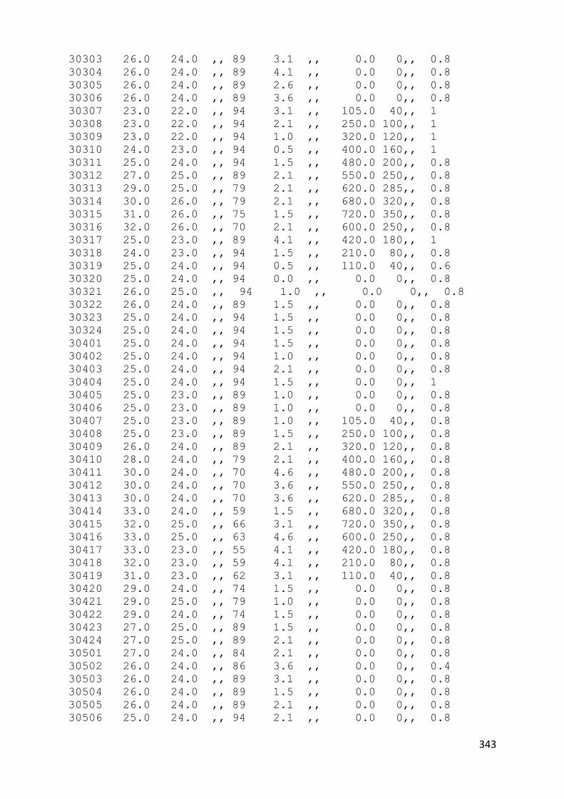
343
30303 26.0 24.0 ,, 89 3.1 ,, 0.0 0,, 0.8
30304 26.0 24.0 ,, 89 4.1 ,, 0.0 0,, 0.8
30305 26.0 24.0 ,, 89 2.6 ,, 0.0 0,, 0.8
30306 26.0 24.0 ,, 89 3.6 ,, 0.0 0,, 0.8
30307 23.0 22.0 ,, 94 3.1 ,, 105.0 40,, 1
30308 23.0 22.0 ,, 94 2.1 ,, 250.0 100,, 1
30309 23.0 22.0 ,, 94 1.0 ,, 320.0 120,, 1
30310 24.0 23.0 ,, 94 0.5 ,, 400.0 160,, 1
30311 25.0 24.0 ,, 94 1.5 ,, 480.0 200,, 0.8
30312 27.0 25.0 ,, 89 2.1 ,, 550.0 250,, 0.8
30313 29.0 25.0 ,, 79 2.1 ,, 620.0 285,, 0.8
30314 30.0 26.0 ,, 79 2.1 ,, 680.0 320,, 0.8
30315 31.0 26.0 ,, 75 1.5 ,, 720.0 350,, 0.8
30316 32.0 26.0 ,, 70 2.1 ,, 600.0 250,, 0.8
30317 25.0 23.0 ,, 89 4.1 ,, 420.0 180,, 1
30318 24.0 23.0 ,, 94 1.5 ,, 210.0 80,, 0.8
30319 25.0 24.0 ,, 94 0.5 ,, 110.0 40,, 0.6
30320 25.0 24.0 ,, 94 0.0 ,, 0.0 0,, 0.8
30321 26.0 25.0 ,, 94 1.0 ,, 0.0 0,, 0.8
30322 26.0 24.0 ,, 89 1.5 ,, 0.0 0,, 0.8
30323 25.0 24.0 ,, 94 1.5 ,, 0.0 0,, 0.8
30324 25.0 24.0 ,, 94 1.5 ,, 0.0 0,, 0.8
30401 25.0 24.0 ,, 94 1.5 ,, 0.0 0,, 0.8
30402 25.0 24.0 ,, 94 1.0 ,, 0.0 0,, 0.8
30403 25.0 24.0 ,, 94 2.1 ,, 0.0 0,, 0.8
30404 25.0 24.0 ,, 94 1.5 ,, 0.0 0,, 1
30405 25.0 23.0 ,, 89 1.0 ,, 0.0 0,, 0.8
30406 25.0 23.0 ,, 89 1.0 ,, 0.0 0,, 0.8
30407 25.0 23.0 ,, 89 1.0 ,, 105.0 40,, 0.8
30408 25.0 23.0 ,, 89 1.5 ,, 250.0 100,, 0.8
30409 26.0 24.0 ,, 89 2.1 ,, 320.0 120,, 0.8
30410 28.0 24.0 ,, 79 2.1 ,, 400.0 160,, 0.8
30411 30.0 24.0 ,, 70 4.6 ,, 480.0 200,, 0.8
30412 30.0 24.0 ,, 70 3.6 ,, 550.0 250,, 0.8
30413 30.0 24.0 ,, 70 3.6 ,, 620.0 285,, 0.8
30414 33.0 24.0 ,, 59 1.5 ,, 680.0 320,, 0.8
30415 32.0 25.0 ,, 66 3.1 ,, 720.0 350,, 0.8
30416 33.0 25.0 ,, 63 4.6 ,, 600.0 250,, 0.8
30417 33.0 23.0 ,, 55 4.1 ,, 420.0 180,, 0.8
30418 32.0 23.0 ,, 59 4.1 ,, 210.0 80,, 0.8
30419 31.0 23.0 ,, 62 3.1 ,, 110.0 40,, 0.8
30420 29.0 24.0 ,, 74 1.5 ,, 0.0 0,, 0.8
30421 29.0 25.0 ,, 79 1.0 ,, 0.0 0,, 0.8
30422 29.0 24.0 ,, 74 1.5 ,, 0.0 0,, 0.8
30423 27.0 25.0 ,, 89 1.5 ,, 0.0 0,, 0.8
30424 27.0 25.0 ,, 89 2.1 ,, 0.0 0,, 0.8
30501 27.0 24.0 ,, 84 2.1 ,, 0.0 0,, 0.8
30502 26.0 24.0 ,, 86 3.6 ,, 0.0 0,, 0.4
30503 26.0 24.0 ,, 89 3.1 ,, 0.0 0,, 0.8
30504 26.0 24.0 ,, 89 1.5 ,, 0.0 0,, 0.8
30505 26.0 24.0 ,, 89 2.1 ,, 0.0 0,, 0.8
30506 25.0 24.0 ,, 94 2.1 ,, 0.0 0,, 0.8

344
30507 25.0 24.0 ,, 94 1.0 ,, 105.0 40,, 0.8
30508 26.0 24.0 ,, 89 1.5 ,, 250.0 100,, 0.8
30509 27.0 24.0 ,, 84 2.6 ,, 320.0 120,, 0.8
30510 28.0 25.0 ,, 84 3.1 ,, 400.0 160,, 0.8
30511 28.0 25.0 ,, 84 2.6 ,, 480.0 200,, 1
30512 28.0 25.0 ,, 84 0.5 ,, 550.0 250,, 1
30513 28.0 25.0 ,, 84 1.0 ,, 620.0 285,, 0.8
30514 28.0 25.0 ,, 84 3.6 ,, 680.0 320,, 1
30515 27.0 25.0 ,, 89 2.6 ,, 720.0 350,, 1
30516 28.0 24.0 ,, 79 3.1 ,, 600.0 250,, 0.8
30517 28.0 24.0 ,, 79 2.6 ,, 420.0 180,, 0.8
30518 28.0 25.0 ,, 84 2.1 ,, 210.0 80,, 0.8
30519 28.0 24.0 ,, 79 3.6 ,, 110.0 40,, 0.8
30520 27.0 24.0 ,, 84 1.5 ,, 0.0 0,, 0.8
30521 27.0 24.0 ,, 84 1.5 ,, 0.0 0,, 0.8
30522 26.0 24.0 ,, 89 1.5 ,, 0.0 0,, 0.8
30523 26.0 23.0 ,, 83 2.1 ,, 0.0 0,, 0.8
30524 26.0 23.0 ,, 83 1.5 ,, 0.0 0,, 0.8
30601 26.0 23.0 ,, 83 1.5 ,, 0.0 0,, 0.8
30602 25.0 24.0 ,, 94 0.5 ,, 0.0 0,, 0.8
30603 25.0 24.0 ,, 94 0.5 ,, 0.0 0,, 0.8
30604 25.0 24.0 ,, 94 1.0 ,, 0.0 0,, 0.8
30605 25.0 24.0 ,, 94 1.0 ,, 0.0 0,, 0.8
30606 24.0 24.0 ,,100 1.5 ,, 0.0 0,, 0.8
30607 24.0 23.0 ,, 94 1.0 ,, 105.0 40,, 0.8
30608 24.0 23.0 ,, 94 1.5 ,, 250.0 100,, 0.8
30609 26.0 24.0 ,, 89 2.1 ,, 320.0 120,, 0.7
30610 26.0 24.0 ,, 89 2.1 ,, 400.0 160,, 0.7
30611 26.0 24.0 ,, 89 2.1 ,, 480.0 200,, 0.7
30612 30.0 25.0 ,, 74 1.5 ,, 550.0 250,, 0.8
30613 31.0 25.0 ,, 70 1.5 ,, 620.0 285,, 0.8
30614 31.0 24.0 ,, 66 2.1 ,, 680.0 320,, 0.8
30615 31.0 25.0 ,, 70 3.1 ,, 720.0 350,, 0.8
30616 32.0 25.0 ,, 66 5.7 ,, 600.0 250,, 0.8
30617 32.0 24.0 ,, 62 4.6 ,, 420.0 180,, 1
30618 32.0 24.0 ,, 62 3.6 ,, 210.0 80,, 0.8
30619 31.0 23.0 ,, 62 3.1 ,, 110.0 40,, 0.8
30620 29.0 24.0 ,, 74 2.1 ,, 0.0 0,, 0.8
30621 28.0 24.0 ,, 79 1.5 ,, 0.0 0,, 0.8
30622 28.0 25.0 ,, 84 1.0 ,, 0.0 0,, 0.8
30623 28.0 25.0 ,, 84 1.0 ,, 0.0 0,, 0.8
30624 28.0 25.0 ,, 84 0.0 ,, 0.0 0,, 0.8
30701 28.0 26.0 ,, 89 0.5 ,, 0.0 0,, 0.8
30702 27.0 25.0 ,, 89 0.0 ,, 0.0 0,, 0.8
30703 26.0 25.0 ,, 94 1.0 ,, 0.0 0,, 0.8
30704 26.0 25.0 ,, 94 1.5 ,, 0.0 0,, 0.8
30705 26.0 25.0 ,, 94 0.0 ,, 0.0 0,, 0.8
30706 26.0 25.0 ,, 94 0.0 ,, 0.0 0,, 0.8
30707 26.0 25.0 ,, 94 0.0 ,, 105.0 40,, 1
30708 25.0 24.0 ,, 94 1.5 ,, 250.0 100,, 1
30709 26.0 24.0 ,, 89 0.5 ,, 320.0 120,, 0.8
30710 28.0 25.0 ,, 84 1.0 ,, 400.0 160,, 0.8

345
30711 30.0 25.0 ,, 74 2.1 ,, 480.0 200,, 0.8
30712 31.0 25.0 ,, 70 1.0 ,, 550.0 250,, 0.8
30713 32.0 25.0 ,, 66 2.1 ,, 620.0 285,, 0.8
30714 32.0 24.0 ,, 57 4.1 ,, 680.0 320,, 0.7
30715 32.0 24.0 ,, 57 4.1 ,, 720.0 350,, 0.7
30716 32.0 24.0 ,, 57 4.1 ,, 600.0 250,, 0.7
30717 32.0 24.0 ,, 57 4.1 ,, 420.0 180,, 0.7
30718 32.0 24.0 ,, 57 4.1 ,, 210.0 80,, 0.7
30719 32.0 24.0 ,, 57 4.1 ,, 110.0 40,, 0.7
30720 26.0 24.0 ,, 90 4.1 ,, 0.0 0,, 1
30721 26.0 24.0 ,, 90 2.1 ,, 0.0 0,, 1
30722 26.0 24.0 ,, 89 0.5 ,, 0.0 0,, 0.8
30723 26.0 24.0 ,, 89 1.0 ,, 0.0 0,, 0.8
30724 25.0 24.0 ,, 94 0.5 ,, 0.0 0,, 0.8
30801 25.0 24.0 ,, 94 1.0 ,, 0.0 0,, 0.8
30802 25.0 24.0 ,, 94 0.0 ,, 0.0 0,, 0.8
30803 24.0 23.0 ,, 94 0.0 ,, 0.0 0,, 0.8
30804 24.0 23.0 ,, 94 0.0 ,, 0.0 0,, 0.8
30805 24.0 23.0 ,, 94 1.5 ,, 0.0 0,, 0.8
30806 24.0 23.0 ,, 94 1.0 ,, 0.0 0,, 0.8
30807 23.0 23.0 ,, 100 1.0 ,, 105.0 40,, 0.8
30808 24.0 23.0 ,, 94 0.0 ,, 250.0 100,, 0.8
30809 26.0 23.0 ,, 83 0.0 ,, 320.0 120,, 0.8
30810 28.0 24.0 ,, 79 0.0 ,, 400.0 160,, 0.8
30811 30.0 23.0 ,, 66 1.5 ,, 480.0 200,, 0.8
30812 31.0 24.0 ,, 66 2.6 ,, 550.0 250,, 0.8
30813 32.0 23.0 ,, 59 4.1 ,, 620.0 285,, 0.8
30814 33.0 24.0 ,, 59 4.6 ,, 680.0 320,, 0.8
30815 33.0 22.0 ,, 52 3.6 ,, 720.0 350,, 0.8
30816 33.0 22.0 ,, 52 3.6 ,, 600.0 250,, 0.8
30817 33.0 21.0 ,, 49 4.1 ,, 420.0 180,, 0.8
30818 32.0 21.0 ,, 52 3.1 ,, 210.0 80,, 0.8
30819 31.0 21.0 ,, 55 3.1 ,, 110.0 40,, 0.8
30820 30.0 21.0 ,, 58 2.1 ,, 0.0 0,, 0.8
30821 28.0 23.0 ,, 74 1.5 ,, 0.0 0,, 0.8
30822 28.0 23.0 ,, 74 1.5 ,, 0.0 0,, 0.8
30823 28.0 22.0 ,, 70 0.0 ,, 0.0 0,, 0.8
30824 27.0 24.0 ,, 84 3.1 ,, 0.0 0,, 0.8
30901 27.0 24.0 ,, 84 2.6 ,, 0.0 0,, 0.8
30902 26.0 24.0 ,, 89 2.6 ,, 0.0 0,, 0.8
30903 26.0 24.0 ,, 89 1.0 ,, 0.0 0,, 0.8
30904 26.0 24.0 ,, 89 2.6 ,, 0.0 0,, 0.8
30905 25.0 24.0 ,, 94 1.0 ,, 0.0 0,, 0.8
30906 26.0 24.0 ,, 89 0.0 ,, 0.0 0,, 0.8
30907 26.0 24.0 ,, 89 0.5 ,, 105.0 40,, 0.8
30908 25.0 24.0 ,, 94 1.0 ,, 250.0 100,, 0.8
30909 27.0 24.0 ,, 84 0.0 ,, 320.0 120,, 0.8
30910 28.0 25.0 ,, 84 1.0 ,, 400.0 160,, 0.8
30911 29.0 24.0 ,, 74 2.1 ,, 480.0 200,, 0.8
30912 31.0 24.0 ,, 66 4.1 ,, 550.0 250,, 0.8
30913 29.0 24.0 ,, 74 4.6 ,, 620.0 285,, 0.8
30914 25.0 24.0 ,, 94 3.1 ,, 680.0 320,, 1

346
30915 25.0 24.0 ,, 94 1.5 ,, 720.0 350,, 1
30916 25.0 24.0 ,, 94 2.1 ,, 600.0 250,, 1
30917 24.0 23.0 ,, 94 1.0 ,, 420.0 180,, 1
30918 24.0 23.0 ,, 94 0.5 ,, 210.0 80,, 1
30919 24.0 23.0 ,, 94 1.0 ,, 110.0 40,, 1
30920 24.0 23.0 ,, 94 2.1 ,, 0.0 0,, 1
30921 24.0 23.0 ,, 94 4.1 ,, 0.0 0,, 1
30922 24.0 22.0 ,, 89 4.6 ,, 0.0 0,, 1
30923 24.0 22.0 ,, 89 2.1 ,, 0.0 0,, 1
30924 23.0 22.0 ,, 94 2.1 ,, 0.0 0,, 0.8
301001 23.0 22.0 ,, 94 2.6 ,, 0.0 0,, 0.8
301002 24.0 22.0 ,, 89 3.1 ,, 0.0 0,, 0.8
301003 23.0 22.0 ,, 94 2.1 ,, 0.0 0,, 1
301004 24.0 22.0 ,, 89 3.1 ,, 0.0 0,, 0.8
301005 24.0 22.0 ,, 89 2.6 ,, 0.0 0,, 0.8
301006 24.0 22.0 ,, 89 1.5 ,, 0.0 0,, 0.8
301007 24.0 22.0 ,, 89 1.0 ,, 105.0 40,, 0.8
301008 24.0 22.0 ,, 89 0.0 ,, 250.0 100,, 0.8
301009 24.0 23.0 ,, 94 1.0 ,, 320.0 120,, 0.8
301010 27.0 24.0 ,, 84 1.0 ,, 400.0 160,, 0.8
301011 29.0 25.0 ,, 79 2.6 ,, 480.0 200,, 0.8
301012 29.0 25.0 ,, 79 3.6 ,, 550.0 250,, 0.8
301013 30.0 25.0 ,, 74 3.6 ,, 620.0 285,, 0.8
301014 30.0 25.0 ,, 74 3.6 ,, 680.0 320,, 0.8
301015 30.0 25.0 ,, 74 3.6 ,, 720.0 350,, 0.8
301016 31.0 25.0 ,, 70 3.1 ,, 600.0 250,, 0.8
301017 31.0 25.0 ,, 70 3.6 ,, 420.0 180,, 0.8
301018 30.0 24.0 ,, 70 3.1 ,, 210.0 80,, 0.8
301019 29.0 23.0 ,, 70 1.5 ,, 110.0 40,, 0.8
301020 28.0 25.0 ,, 84 2.1 ,, 0.0 0,, 1
301021 27.0 24.0 ,, 84 2.1 ,, 0.0 0,, 1
301022 26.0 24.0 ,, 89 1.5 ,, 0.0 0,, 0.8
301023 26.0 24.0 ,, 89 0.5 ,, 0.0 0,, 0.8
301024 25.0 23.0 ,, 89 1.0 ,, 0.0 0,, 1
301101 25.0 24.0 ,, 94 0.0 ,, 0.0 0,, 1
301102 25.0 24.0 ,, 94 1.5 ,, 0.0 0,, 0.8
301103 25.0 24.0 ,, 94 2.1 ,, 0.0 0,, 0.8
301104 25.0 24.0 ,, 94 1.5 ,, 0.0 0,, 0.8
301105 25.0 24.0 ,, 94 1.5 ,, 0.0 0,, 0.8
301106 25.0 24.0 ,, 94 1.0 ,, 0.0 0,, 0.8
301107 25.0 24.0 ,, 94 1.5 ,, 105.0 40,, 0.8
301108 26.0 24.0 ,, 89 1.5 ,, 250.0 100,, 0.8
301109 27.0 24.0 ,, 84 3.1 ,, 320.0 120,, 0.8
301110 29.0 24.0 ,, 74 3.6 ,, 400.0 160,, 0.8
301111 29.0 24.0 ,, 74 3.6 ,, 480.0 200,, 0.8
301112 31.0 23.0 ,, 62 1.5 ,, 550.0 250,, 0.8
301113 31.0 25.0 ,, 70 1.5 ,, 620.0 285,, 0.8
301114 29.0 25.0 ,, 79 4.1 ,, 680.0 320,, 0.8
301115 27.0 24.0 ,, 84 4.1 ,, 720.0 350,, 1
301116 27.0 24.0 ,, 84 2.1 ,, 600.0 250,, 1
301117 27.0 24.0 ,, 84 1.5 ,, 420.0 180,, 0.8
301118 27.0 25.0 ,, 89 1.5 ,, 210.0 80,, 0.8

347
301119 26.0 23.0 ,, 83 3.6 ,, 110.0 40,, 0.8
301120 25.0 23.0 ,, 89 1.5 ,, 0.0 0,, 1
301121 25.0 23.0 ,, 89 1.5 ,, 0.0 0,, 0.8
301122 25.0 23.0 ,, 89 1.5 ,, 0.0 0,, 0.8
301123 24.0 23.0 ,, 94 2.6 ,, 0.0 0,, 0.8
301124 27.0 24.0 ,, 84 3.1 ,, 0.0 0,, 0.8
301201 27.0 24.0 ,, 84 2.6 ,, 0.0 0,, 0.8
301202 26.0 24.0 , , 89 2.6 , , 0.0 0 , ,
0.8
301203 26.0 24.0 , , 89 1.0 , , 0.0 0
, , 0.8
301204 26.0 24.0 , , 89 2.6 , , 0.0 0 ,
, 0.8
301205 25.0 24.0 , , 94 1.0 , , 0.0 0 ,
, 0.8
301206 26.0 24.0 , , 89 0.0 , , 0.0 0 ,
, 0.8
301207 26.0 24.0 , , 89 0.5 , , 105.0 40
, , 0.8
301208 25.0 24.0 , , 94 1.0 , , 250.0
100 , , 0.8
301209 27.0 24.0 , , 84 0.0 , , 320.0
120 , , 0.8
301210 28.0 25.0 , , 84 1.0 , , 400.0
160 , , 0.8
301211 29.0 24.0 , , 74 2.1 , , 520.0
200 , , 0.8
301212 31.0 24.0 , , 66 4.1 , , 650.0
250 , , 0.8
301213 29.0 24.0 , , 74 4.6 , , 720.0
285 , , 0.8
301214 25.0 24.0 , , 94 3.1 , , 800.0
320 , , 1
301215 25.0 24.0 , , 94 1.5 , , 820.0
350 , , 1
301216 25.0 24.0 , , 94 2.1 , , 600.0
250 , , 1
301217 24.0 23.0 , , 94 1.0 , , 420.0
180 , , 1
301218 24.0 23.0 , , 94 0.5 , , 210.0 80
, , 1
301219 24.0 23.0 , , 94 1.0 , , 110.0 40
, , 1
301220 24.0 23.0 , , 94 2.1 , , 0.0 0 ,
, 1
301221 24.0 23.0 , , 94 4.1 , , 0.0 0 ,
, 1
301222 24.0 22.0 , , 89 4.6 , , 0.0 0 ,
, 1
301223 24.0 22.0 , , 89 2.1 , , 0.0 0 ,
, 1
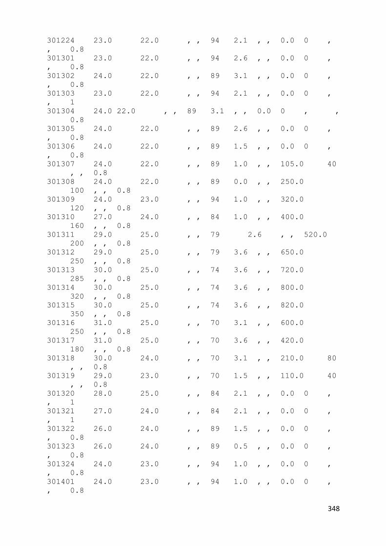
348
301224 23.0 22.0 , , 94 2.1 , , 0.0 0 ,
, 0.8
301301 23.0 22.0 , , 94 2.6 , , 0.0 0 ,
, 0.8
301302 24.0 22.0 , , 89 3.1 , , 0.0 0 ,
, 0.8
301303 23.0 22.0 , , 94 2.1 , , 0.0 0 ,
, 1
301304 24.0 22.0 , , 89 3.1 , , 0.0 0 , ,
0.8
301305 24.0 22.0 , , 89 2.6 , , 0.0 0 ,
, 0.8
301306 24.0 22.0 , , 89 1.5 , , 0.0 0 ,
, 0.8
301307 24.0 22.0 , , 89 1.0 , , 105.0 40
, , 0.8
301308 24.0 22.0 , , 89 0.0 , , 250.0
100 , , 0.8
301309 24.0 23.0 , , 94 1.0 , , 320.0
120 , , 0.8
301310 27.0 24.0 , , 84 1.0 , , 400.0
160 , , 0.8
301311 29.0 25.0 , , 79 2.6 , , 520.0
200 , , 0.8
301312 29.0 25.0 , , 79 3.6 , , 650.0
250 , , 0.8
301313 30.0 25.0 , , 74 3.6 , , 720.0
285 , , 0.8
301314 30.0 25.0 , , 74 3.6 , , 800.0
320 , , 0.8
301315 30.0 25.0 , , 74 3.6 , , 820.0
350 , , 0.8
301316 31.0 25.0 , , 70 3.1 , , 600.0
250 , , 0.8
301317 31.0 25.0 , , 70 3.6 , , 420.0
180 , , 0.8
301318 30.0 24.0 , , 70 3.1 , , 210.0 80
, , 0.8
301319 29.0 23.0 , , 70 1.5 , , 110.0 40
, , 0.8
301320 28.0 25.0 , , 84 2.1 , , 0.0 0 ,
, 1
301321 27.0 24.0 , , 84 2.1 , , 0.0 0 ,
, 1
301322 26.0 24.0 , , 89 1.5 , , 0.0 0 ,
, 0.8
301323 26.0 24.0 , , 89 0.5 , , 0.0 0 ,
, 0.8
301324 24.0 23.0 , , 94 1.0 , , 0.0 0 ,
, 0.8
301401 24.0 23.0 , , 94 1.0 , , 0.0 0 ,
, 0.8
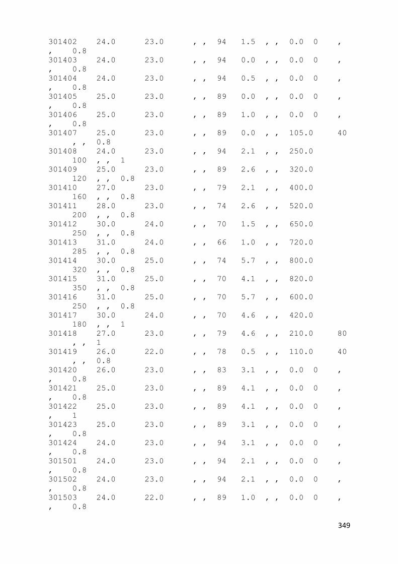
349
301402 24.0 23.0 , , 94 1.5 , , 0.0 0 ,
, 0.8
301403 24.0 23.0 , , 94 0.0 , , 0.0 0 ,
, 0.8
301404 24.0 23.0 , , 94 0.5 , , 0.0 0 ,
, 0.8
301405 25.0 23.0 , , 89 0.0 , , 0.0 0 ,
, 0.8
301406 25.0 23.0 , , 89 1.0 , , 0.0 0 ,
, 0.8
301407 25.0 23.0 , , 89 0.0 , , 105.0 40
, , 0.8
301408 24.0 23.0 , , 94 2.1 , , 250.0
100 , , 1
301409 25.0 23.0 , , 89 2.6 , , 320.0
120 , , 0.8
301410 27.0 23.0 , , 79 2.1 , , 400.0
160 , , 0.8
301411 28.0 23.0 , , 74 2.6 , , 520.0
200 , , 0.8
301412 30.0 24.0 , , 70 1.5 , , 650.0
250 , , 0.8
301413 31.0 24.0 , , 66 1.0 , , 720.0
285 , , 0.8
301414 30.0 25.0 , , 74 5.7 , , 800.0
320 , , 0.8
301415 31.0 25.0 , , 70 4.1 , , 820.0
350 , , 0.8
301416 31.0 25.0 , , 70 5.7 , , 600.0
250 , , 0.8
301417 30.0 24.0 , , 70 4.6 , , 420.0
180 , , 1
301418 27.0 23.0 , , 79 4.6 , , 210.0 80
, , 1
301419 26.0 22.0 , , 78 0.5 , , 110.0 40
, , 0.8
301420 26.0 23.0 , , 83 3.1 , , 0.0 0 ,
, 0.8
301421 25.0 23.0 , , 89 4.1 , , 0.0 0 ,
, 0.8
301422 25.0 23.0 , , 89 4.1 , , 0.0 0 ,
, 1
301423 25.0 23.0 , , 89 3.1 , , 0.0 0 ,
, 0.8
301424 24.0 23.0 , , 94 3.1 , , 0.0 0 ,
, 0.8
301501 24.0 23.0 , , 94 2.1 , , 0.0 0 ,
, 0.8
301502 24.0 23.0 , , 94 2.1 , , 0.0 0 ,
, 0.8
301503 24.0 22.0 , , 89 1.0 , , 0.0 0 ,
, 0.8

350
301504 24.0 22.0 , , 89 1.0 , , 0.0 0 , ,
0.8
301505 24.0 22.0 , , 89 2.1 , , 0.0 0 ,
, 0.8
301506 23.0 22.0 , , 94 1.0 , , 0.0 0 ,
, 0.8
301507 24.0 22.0 , , 89 1.0 , , 105.0 40
, , 0.8
301508 24.0 22.0 , , 89 1.5 , , 250.0
100 , , 0.8
301509 25.0 22.0 , , 83 0.5 , , 320.0
120 , , 0.8
301510 27.0 22.0 , , 74 4.6 , , 400.0 160 ,
, 0.8
301511 28.0 23.0 , , 74 4.1 , , 520.0
200 , , 0.8
301512 30.0 22.0 , , 62 6.7 , , 650.0
250 , , 0.8
301513 30.0 23.0 , , 66 5.7 , , 720.0
285 , , 0.8
301514 31.0 23.0 , , 62 5.7 , , 800.0
320 , , 0.8
301515 31.0 23.0 , , 62 5.1 , , 820.0
350 , , 0.8
301516 31.0 23.0 , , 62 4.6 , , 600.0
250 , , 0.8
301517 30.0 23.0 , , 66 4.1 , , 420.0
180 , , 0.8
301518 30.0 23.0 , , 66 4.1 , , 210.0 80
, , 0.8
301519 28.0 22.0 , , 70 5.7 , , 110.0 40
, , 0.8
301520 26.0 23.0 , , 83 4.6 , , 0.0 0
, , 0.8
301521 26.0 23.0 , , 83 4.1 , , 0.0 0 ,
, 0.8
301522 26.0 23.0 , , 83 3.1 , , 0.0 0 ,
, 0.8
301523 25.0 23.0 , , 89 3.1 , , 0.0 0 ,
, 0.8
301524 25.0 23.0 , , 89 2.1 , , 0.0 0 ,
, 0.8
301601 25.0 23.0 , , 89 3.6 , , 0.0 0 ,
, 0.8
301602 25.0 23.0 , , 89 4.1 , , 0.0 0 , ,
0.8
301603 25.0 23.0 , , 89 2.6 , , 0.0 0 ,
, 0.8
301604 25.0 23.0 , , 89 3.1 , , 0.0 0 ,
, 0.8
301605 25.0 23.0 , , 89 2.1 , , 0.0 0 ,
, 0.8

351
301606 25.0 23.0 , , 89 1.5 , , 0.0 0 ,
, 0.8
301607 25.0 23.0 , , 89 2.6 , , 105.0 40 ,
, 0.8
301608 25.0 23.0 , , 89 2.1 , , 250.0
100 , , 0.8
301609 26.0 23.0 , , 83 2.6 , , 320.0
120 , , 0.8
301610 28.0 23.0 , , 74 3.6 , , 400.0
160 , , 0.8
301611 29.0 23.0 , , 70 4.1 , , 520.0
200 , , 0.8
301612 30.0 23.0 , , 66 3.1 , , 650.0
250 , , 0.8
301613 30.0 23.0 , , 66 1.5 , , 720.0
285 , , 0.8
301614 30.0 23.0 , , 66 3.1 , , 800.0
320 , , 0.8
301615 27.0 23.0 , , 79 3.6 , , 820.0
350 , , 0.8
301616 26.0 23.0 , , 83 2.1 , , 600.0
250 , , 1
301617 26.0 23.0 , , 83 1.5 , , 420.0
180 , , 0.8
301618 26.0 24.0 , , 89 1.5 , , 210.0 80 ,
, 1
301619 26.0 24.0 , , 89 1.5 , , 110.0 40
, , 1
301620 25.0 24.0 , , 94 0.5 , , 0.0 0 ,
, 1
301621 25.0 24.0 , , 94 2.1 , , 0.0 0 ,
, 0.8
301622 25.0 23.0 , , 89 2.1 , , 0.0 0 ,
, 0.8
301623 25.0 23.0 , , 89 2.1 , , 0.0 0 ,
, 0.8
301624 25.0 23.0 , , 89 2.1 , , 0.0 0 ,
, 0.8
301701 25.0 23.0 , , 89 1.5 , , 0.0 0 ,
, 0.8
301702 25.0 23.0 , , 89 2.6 , , 0.0 0
, , 0.8
301703 24.0 23.0 , , 94 1.5 , , 0.0 0 , ,
0.8
301704 24.0 23.0 , , 94 2.1 , , 0.0 0 ,
, 0.8
301705 24.0 23.0 , , 94 1.5 , , 0.0 0 ,
, 0.8
301706 24.0 23.0 , , 94 2.1 , , 0.0 0 , ,
0.8
301707 24.0 23.0 , , 94 2.6 , , 105.0 40
, , 1

352
301708 24.0 23.0 , , 94 1.5 , , 250.0
100 , , 0.8
301709 24.0 23.0 , , 94 2.1 , , 320.0
120 , , 1
301710 25.0 23.0 , , 89 2.6 , , 400.0
160 , , 0.8
301711 27.0 23.0 , , 79 2.1 , , 520.0
200 , , 0.8
301712 26.0 24.0 , , 89 1.5 , , 650.0
250 , , 1
301713 28.0 24.0 , , 79 1.5 , , 720.0
285 , , 0.8
301714 30.0 23.0 , , 66 1.0 , , 800.0
320 , , 0.8
301715 31.0 25.0 , , 70 3.6 , , 820.0
350 , , 0.8
301716 31.0 24.0 , , 66 3.1 , , 600.0 250 ,
, 0.8
301717 31.0 23.0 , , 62 2.6 , , 420.0
180 , , 0.8
301718 31.0 24.0 , , 66 1.5 , , 210.0 80 ,
, 0.8
301719 30.0 23.0 , , 66 2.1 , , 110.0 40
, , 0.8
301720 29.0 24.0 , , 74 1.5 , , 0.0 0 ,
, 0.8
301721 28.0 24.0 , , 79 1.0 , , 0.0 0 ,
, 0.8
301722 27.0 24.0 , , 84 1.0 , , 0.0 0 , ,
0.8
301723 27.0 24.0 , , 84 0.5 , , 0.0 0 ,
, 0.8
301724 26.0 24.0 , , 89 0.5 , , 0.0 0
, , 0.8
301801 26.0 24.0 , , 89 1.5 , , 0.0 0 , ,
0.8
301802 26.0 24.0 , , 89 1.5 , , 0.0 0
, , 0.8
301803 26.0 23.0 , , 83 1.5 , , 0.0 0 , ,
0.8
301804 25.0 23.0 , , 89 1.5 , , 0.0 0 ,
, 0.8
301805 25.0 23.0 , , 89 0.0 , , 0.0 0 , ,
0.8
301806 25.0 23.0 , , 89 0.5 , , 0.0 0 ,
, 0.8
301807 25.0 23.0 , , 89 0.0 , , 105.0 40
, , 0.8
301808 25.0 23.0 , , 89 1.0 , , 250.0
100 , , 0.8
301809 26.0 23.0 , , 83 3.1 , , 320.0 120 ,
, 0.8

353
301810 27.0 23.0 , , 79 1.0 , , 400.0 160 ,
, 0.8
301811 29.0 23.0 , , 70 1.0 , , 520.0
200 , , 0.8
301812 31.0 23.0 , , 62 2.1 , , 650.0
250 , , 0.8
301813 31.0 24.0 , , 66 4.1 , , 720.0
285 , , 0.8
301814 32.0 24.0 , , 62 3.6 , , 800.0
320 , , 0.8
301815 32.0 24.0 , , 62 5.1 , , 820.0
350 , , 0.8
301816 33.0 24.0 , , 59 4.1 , , 600.0
250 , , 0.8
301817 33.0 23.0 , , 55 4.1 , , 420.0
180 , , 0.8
301818 32.0 23.0 , , 59 3.6 , , 210.0 80
, , 0.8
301819 31.0 23.0 , , 62 3.1 , , 110.0 40
, , 0.8
301820 30.0 23.0 , , 66 2.1 , , 0.0 0 ,
, 0.8
301821 29.0 23.0 , , 70 1.0 , , 0.0 0 ,
, 0.8
301822 29.0 24.0 , , 74 0.0 , , 0.0 0 ,
, 0.8
301823 28.0 24.0 , , 79 0.0 , , 0.0 0 ,
, 0.8
301824 27.0 24.0 , , 84 0.5 , , 0.0 0 ,
, 0.8
301901 26.0 24.0 , , 89 0.5 , , 0.0 0 ,
, 0.8
301902 26.0 24.0 , , 89 0.5 , , 0.0 0 ,
, 0.8
301903 27.0 23.0 , , 79 2.1 , , 0.0 0 ,
, 0.8
301904 26.0 23.0 , , 83 0.0 , , 0.0 0 ,
, 1
301905 26.0 24.0 , , 89 0.5 , , 0.0 0 ,
, 1
301906 25.0 24.0 , , 94 0.5 , , 0.0 0 , ,
0.8
301907 25.0 24.0 , , 94 1.5 , , 105.0 40
, , 0.8
301908 25.0 24.0 , , 94 1.0 , , 250.0
100 , , 0.8
301909 27.0 24.0 , , 84 2.1 , , 320.0
120 , , 0.8
301910 29.0 25.0 , , 79 3.6 , , 400.0
160 , , 0.8
301911 30.0 24.0 , , 70 3.1 , , 520.0
200 , , 0.8

354
301912 32.0 24.0 , , 62 3.6 , , 650.0
250 , , 0.8
301913 31.0 25.0 , , 70 1.5 , , 720.0
285 , , 0.8
301914 32.0 25.0 , , 66 2.6 , , 800.0
320 , , 0.8
301915 30.0 25.0 , , 74 5.1 , , 820.0
350 , , 0.8
301916 30.0 25.0 , , 74 3.1 , , 600.0
250 , , 1
301917 30.0 24.0 , , 70 3.6 , , 420.0
180 , , 1
301918 30.0 24.0 , , 70 3.1 , , 210.0 80
, , 0.8
301919 30.0 24.0 , , 70 2.6 , , 110.0 40 ,
, 0.8
301920 29.0 24.0 , , 74 1.0 , , 0.0 0 ,
, 0.8
301921 29.0 25.0 , , 79 0.0 , , 0.0 0 ,
, 0.8
301922 28.0 25.0 , , 84 1.0 , , 0.0 0 ,
, 0.8
301923 27.0 25.0 , , 89 1.5 , , 0.0 0 ,
, 0.8
301924 27.0 25.0 , , 89 0.5 , , 0.0 0 , ,
0.8
302001 26.0 25.0 , , 94 1.5 , , 0.0 0 ,
, 0.8
302002 26.0 24.0 , , 89 1.5 , , 0.0 0 , , 1
302003 26.0 25.0 , , 94 0.0 , , 0.0 0 ,
, 1
302004 24.0 22.0 , , 89 2.1 , , 0.0 0 ,
, 1
302005 25.0 23.0 , , 89 0.5 , , 0.0 0 ,
, 1
302006 24.0 23.0 , , 94 1.0 , , 0.0 0 ,
, 1
302007 24.0 23.0 , , 94 1.5 , , 105.0 40
, , 0.8
302008 25.0 23.0 , , 89 1.5 , , 250.0
100 , , 0.8
302009 26.0 24.0 , , 89 2.6 , , 320.0
120 , , 0.8
302010 28.0 25.0 , , 84 2.1 , , 400.0
160 , , 0.8
302011 30.0 25.0 , , 74 1.0 , , 520.0
200 , , 0.8
302012 32.0 25.0 , , 66 1.5 , , 650.0
250 , , 0.8
302013 31.0 26.0 , , 75 4.1 , , 720.0
285 , , 0.8

355
302014 29.0 25.0 , , 79 3.1 , , 800.0
320 , , 1
302015 29.0 24.0 , , 74 0.5 , , 820.0 350 ,
, 1
302016 28.0 25.0 , , 84 1.5 , , 600.0
250 , , 0.8
302017 28.0 25.0 , , 84 3.1 , , 420.0
180 , , 0.8
302018 28.0 25.0 , , 84 1.0 , , 210.0 80
, , 0.8
302019 28.0 25.0 , , 84 1.5 , , 110.0 40
, , 0.8
302020 27.0 25.0 , , 89 0.5 , , 0.0 0 ,
, 0.8
302021 27.0 25.0 , , 89 0.5 , , 0.0 0 ,
, 0.8
302022 27.0 25.0 , , 89 1.5 , , 0.0 0 ,
, 0.8
302023 26.0 25.0 , , 94 0.0 , , 0.0 0 ,
, 0.8
302024 26.0 24.0 , , 89 4.1 , , 0.0 0 ,
, 0.8
302101 25.0 23.0 , , 89 1.5 , , 0.0 0 , ,
0.8
302102 25.0 23.0 , , 89 2.1 , , 0.0 0 ,
, 1
302103 25.0 23.0 , , 89 2.6 , , 0.0 0 ,
, 0.8
302104 24.0 23.0 , , 94 2.1 , , 0.0 0 ,
, 0.8
302105 24.0 23.0 , , 94 1.0 , , 0.0 0 ,
, 0.8
302106 25.0 23.0 , , 89 0.0 , , 0.0 0 ,
, 0.8
302107 24.0 23.0 , , 94 0.5 , , 105.0 40
, , 0.8
302108 25.0 23.0 , , 89 0.5 , , 250.0
100 , , 0.8
302109 26.0 22.0 , , 78 1.0 , , 320.0
120 , , 0.8
302110 27.0 23.0 , , 79 0.5 , , 400.0 160 ,
, 0.8
302111 29.0 23.0 , , 70 0.5 , , 520.0
200 , , 0.8
302112 31.0 24.0 , , 66 2.1 , , 650.0
250 , , 0.8
302113 32.0 23.0 , , 59 3.6 , , 720.0 285 ,
, 0.8
302114 32.0 23.0 , , 59 2.6 , , 800.0
320 , , 0.8
302115 32.0 24.0 , , 62 3.6 , , 820.0
350 , , 0.8

356
302116 32.0 22.0 , , 55 4.1 , , 600.0
250 , , 0.8
302117 32.0 21.0 , , 52 4.6 , , 420.0
180 , , 0.8
302118 31.0 22.0 , , 58 3.6 , , 210.0 80
, , 0.8
302119 30.0 22.0 , , 62 2.1 , , 110.0 40
, , 0.8
302120 29.0 23.0 , , 70 1.0 , , 0.0 0 ,
, 0.8
302121 29.0 23.0 , , 70 1.5 , , 0.0 0 , ,
0.8
302122 28.0 23.0 , , 74 1.5 , , 0.0 0 ,
, 0.8
302123 27.0 23.0 , , 79 1.0 , , 0.0 0 ,
, 0.8
302124 27.0 23.0 , , 79 1.5 , , 0.0 0 ,
, 0.8
302201 27.0 23.0 , , 79 1.5 , , 0.0 0 ,
, 0.8
302202 26.0 23.0 , , 83 2.6 , , 0.0 0 , ,
0.8
302203 26.0 23.0 , , 83 1.0 , , 0.0 0 ,
, 0.8
302204 23.0 22.0 , , 94 4.6 , , 0.0 0 ,
, 1
302205 23.0 23.0 , , 100 0.5 , , 0.0 0 , , 1
302206 24.0 23.0 , , 94 0.0 , , 0.0 0 ,
, 0.8
302207 24.0 23.0 , , 94 1.5 , , 105.0 40 ,
, 0.8
302208 24.0 23.0 , , 94 1.5 , , 250.0
100 , , 0.8
302209 25.0 23.0 , , 89 1.0 , , 320.0
120 , , 0.8
302210 26.0 23.0 , , 83 1.5 , , 400.0
160 , , 0.8
302211 28.0 24.0 , , 79 1.0 , , 520.0
200 , , 0.8
302212 29.0 25.0 , , 79 1.0 , , 650.0
250 , , 0.8
302213 30.0 24.0 , , 70 1.0 , , 720.0
285 , , 0.8
302214 30.0 24.0 , , 70 2.6 , , 800.0
320 , , 0.8
302215 31.0 24.0 , , 66 2.6 , , 820.0
350 , , 0.8
302216 30.0 24.0 , , 70 3.1 , , 600.0
250 , , 0.8
302217 30.0 23.0 , , 66 3.6 , , 420.0
180 , , 0.8
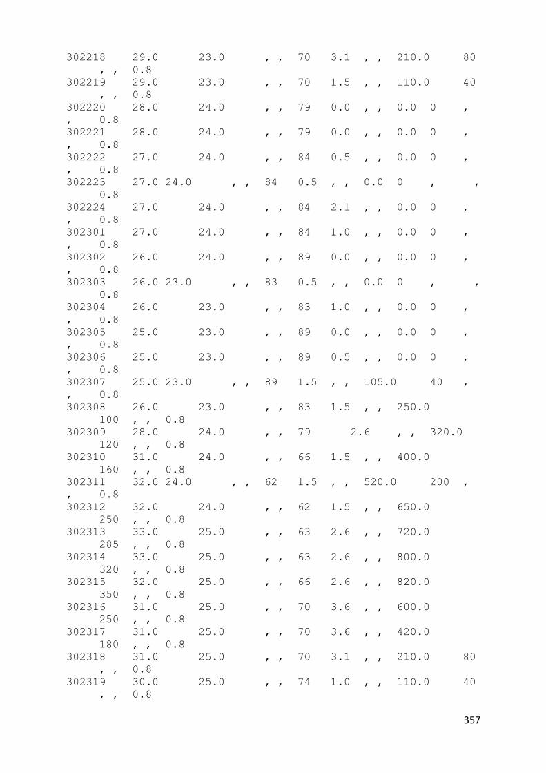
357
302218 29.0 23.0 , , 70 3.1 , , 210.0 80
, , 0.8
302219 29.0 23.0 , , 70 1.5 , , 110.0 40
, , 0.8
302220 28.0 24.0 , , 79 0.0 , , 0.0 0 ,
, 0.8
302221 28.0 24.0 , , 79 0.0 , , 0.0 0 ,
, 0.8
302222 27.0 24.0 , , 84 0.5 , , 0.0 0 ,
, 0.8
302223 27.0 24.0 , , 84 0.5 , , 0.0 0 , ,
0.8
302224 27.0 24.0 , , 84 2.1 , , 0.0 0 ,
, 0.8
302301 27.0 24.0 , , 84 1.0 , , 0.0 0 ,
, 0.8
302302 26.0 24.0 , , 89 0.0 , , 0.0 0 ,
, 0.8
302303 26.0 23.0 , , 83 0.5 , , 0.0 0 , ,
0.8
302304 26.0 23.0 , , 83 1.0 , , 0.0 0 ,
, 0.8
302305 25.0 23.0 , , 89 0.0 , , 0.0 0 ,
, 0.8
302306 25.0 23.0 , , 89 0.5 , , 0.0 0 ,
, 0.8
302307 25.0 23.0 , , 89 1.5 , , 105.0 40 ,
, 0.8
302308 26.0 23.0 , , 83 1.5 , , 250.0
100 , , 0.8
302309 28.0 24.0 , , 79 2.6 , , 320.0
120 , , 0.8
302310 31.0 24.0 , , 66 1.5 , , 400.0
160 , , 0.8
302311 32.0 24.0 , , 62 1.5 , , 520.0 200 ,
, 0.8
302312 32.0 24.0 , , 62 1.5 , , 650.0
250 , , 0.8
302313 33.0 25.0 , , 63 2.6 , , 720.0
285 , , 0.8
302314 33.0 25.0 , , 63 2.6 , , 800.0
320 , , 0.8
302315 32.0 25.0 , , 66 2.6 , , 820.0
350 , , 0.8
302316 31.0 25.0 , , 70 3.6 , , 600.0
250 , , 0.8
302317 31.0 25.0 , , 70 3.6 , , 420.0
180 , , 0.8
302318 31.0 25.0 , , 70 3.1 , , 210.0 80
, , 0.8
302319 30.0 25.0 , , 74 1.0 , , 110.0 40
, , 0.8

358
302320 29.0 25.0 , , 79 0.0 , , 0.0 0
, , 0.8
302321 29.0 25.0 , , 79 0.5 , , 0.0 0 ,
, 0.8
302322 28.0 25.0 , , 84 0.5 , , 0.0 0 ,
, 0.8
302323 28.0 25.0 , , 84 0.5 , , 0.0 0 ,
, 0.8
302324 28.0 24.0 , , 79 1.0 , , 0.0 0 ,
, 0.8
302401 27.0 24.0 , , 84 1.5 , , 0.0 0 ,
, 0.8
302402 26.0 24.0 , , 89 1.5 , , 0.0 0 ,
, 0.8
302403 26.0 24.0 , , 89 2.1 , , 0.0 0 ,
, 0.8
302404 26.0 24.0 , , 89 3.1 , , 0.0 0 ,
, 0.8
302405 26.0 24.0 , , 89 1.5 , , 0.0 0 ,
, 0.8
302406 26.0 24.0 , , 89 0.5 , , 0.0 0 ,
, 0.8
302407 26.0 24.0 , , 89 0.5 , , 105.0 40
, , 0.7
302408 27.0 24.0 , , 84 1.0 , , 250.0
100 , , 1
302409 27.0 24.0 , , 84 1.5 , , 320.0
120 , , 1
302410 23.0 22.0 , , 94 2.6 , , 400.0
160 , , 1
302411 24.0 23.0 , , 94 0.0 , , 520.0
200 , , 1
302412 25.0 23.0 , , 89 1.5 , , 650.0 250 ,
, 0.8
302413 24.0 23.0 , , 94 2.6 , , 720.0
285 , , 1
302414 25.0 23.0 , , 89 1.5 , , 800.0
320 , , 1
302415 27.0 24.0 , , 84 1.5 , , 820.0
350 , , 0.8
302416 28.0 24.0 , , 79 2.1 , , 600.0 250 ,
, 0.8
302417 28.0 24.0 , , 79 1.0 , , 420.0
180 , , 0.8
302418 27.0 24.0 , , 84 2.1 , , 210.0 80
, , 0.8
302419 27.0 24.0 , , 84 1.0 , , 110.0 40
, , 0.8
302420 26.0 24.0 , , 89 1.5 , , 0.0 0 , ,
0.8
302421 26.0 24.0 , , 89 0.0 , , 0.0 0 ,
, 0.8

359
302422 26.0 24.0 , , 89 1.0 , , 0.0 0 ,
, 0.8
302423 26.0 24.0 , , 89 1.5 , , 0.0 0 ,
, 0.8
302424 25.0 23.0 , , 89 1.5 , , 0.0 0 , ,
0.8
302501 25.0 23.0 , , 89 1.5 , , 0.0 0 , ,
0.8
302502 25.0 23.0 , , 89 1.5 , , 0.0 0 ,
, 0.8
302503 24.0 23.0 , , 94 1.0 , , 0.0 0 , ,
0.8
302504 24.0 23.0 , , 94 1.0 , , 0.0 0 ,
, 0.8
302505 24.0 23.0 , , 94 1.0 , , 0.0 0 , ,
0.8
302506 24.0 23.0 , , 94 0.5 , , 0.0 0 ,
, 0.8
302507 24.0 23.0 , , 94 1.0 , , 105.0 40 ,
, 0.8
302508 24.0 23.0 , , 94 1.5 , , 250.0
100 , , 0.8
302509 26.0 23.0 , , 83 1.0 , , 320.0
120 , , 0.8
302510 28.0 24.0 , , 79 1.5 , , 400.0
160 , , 0.3
302511 29.0 24.0 , , 74 1.0 , , 520.0
200 , , 0.8
302512 31.0 24.0 , , 66 2.1 , , 650.0
250 , , 0.8
302513 30.0 25.0 , , 74 5.1 , , 720.0
285 , , 0.8
302514 28.0 24.0 , , 79 4.1 , , 800.0
320 , , 1
302515 27.0 24.0 , , 84 3.6 , , 820.0
350 , , 1
302516 26.0 24.0 , , 89 2.1 , , 600.0
250 , , 0.8
302517 30.0 24.0 , , 70 3.1 , , 420.0 180 ,
, 0.8
302518 30.0 24.0 , , 70 2.6 , , 210.0 80
, , 0.8
302519 29.0 25.0 , , 79 1.5 , , 110.0 40
, , 0.8
302520 28.0 24.0 , , 79 2.1 , , 0.0 0 ,
, 0.8
302521 26.0 25.0 , , 94 2.6 , , 0.0 0 , ,
0.8
302522 27.0 24.0 , , 84 1.5 , , 0.0 0 ,
, 0.8
302523 26.0 23.0 , , 83 1.0 , , 0.0 0 ,
, 0.8

360
302524 25.0 22.0 , , 83 1.0 , , 0.0 0 ,
, 0.8
302601 25.0 23.0 , , 89 1.0 , , 0.0 0 ,
, 0.8
302602 25.0 23.0 , , 89 0.0 , , 0.0 0 ,
, 0.8
302603 25.0 23.0 , , 89 0.0 , , 0.0 0 , ,
0.8
302604 24.0 23.0 , , 94 0.0 , , 0.0 0 ,
, 0.8
302605 24.0 23.0 , , 94 0.0 , , 0.0 0 ,
, 0.8
302606 24.0 23.0 , , 94 0.0 , , 0.0 0 ,
, 0.8
302607 24.0 23.0 , , 94 1.0 , , 105.0 40
, , 0.8
302608 25.0 24.0 , , 94 0.5 , , 250.0 100 ,
, 0.8
302609 27.0 24.0 , , 84 0.0 , , 320.0
120 , , 0.8
302610 29.0 24.0 , , 74 0.5 , , 400.0
160 , , 0.8
302611 30.0 24.0 , , 70 2.1 , , 520.0
200 , , 0.8
302612 31.0 24.0 , , 66 0.5 , , 650.0
250 , , 0.8
302613 29.0 25.0 , , 79 3.6 , , 720.0 285 ,
, 0.8
302614 30.0 26.0 , , 79 4.1 , , 800.0
320 , , 0.8
302615 31.0 25.0 , , 70 1.0 , , 820.0
350 , , 1
302616 30.0 25.0 , , 74 3.6 , , 600.0 250 ,
, 0.8
302617 30.0 25.0 , , 74 3.1 , , 420.0
180 , , 0.8
302618 27.0 21.0 , , 70 3.6 , , 210.0 80
, , 0.8
302619 26.0 23.0 , , 83 2.6 , , 110.0 40
, , 0.8
302620 26.0 23.0 , , 83 2.1 , , 0.0 0 ,
, 0.8
302621 26.0 23.0 , , 83 1.5 , , 0.0 0 ,
, 0.8
302622 25.0 23.0 , , 89 2.1 , , 0.0 0 , ,
0.8
302623 26.0 24.0 , , 89 0.0 , , 0.0 0 ,
, 0.8
302624 26.0 24.0 , , 89 0.5 , , 0.0 0 ,
, 0.8
302701 25.0 23.0 , , 89 2.6 , , 0.0 0 , ,
0.8
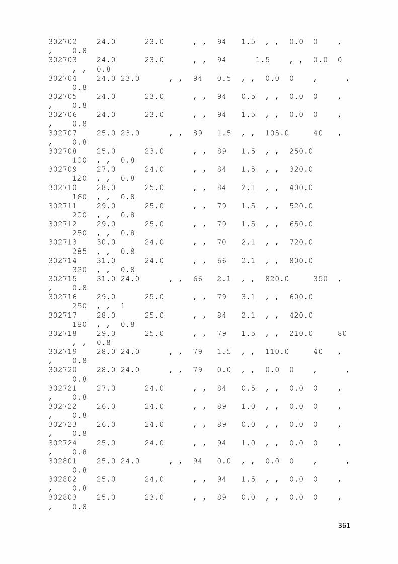
361
302702 24.0 23.0 , , 94 1.5 , , 0.0 0 ,
, 0.8
302703 24.0 23.0 , , 94 1.5 , , 0.0 0
, , 0.8
302704 24.0 23.0 , , 94 0.5 , , 0.0 0 , ,
0.8
302705 24.0 23.0 , , 94 0.5 , , 0.0 0 ,
, 0.8
302706 24.0 23.0 , , 94 1.5 , , 0.0 0 ,
, 0.8
302707 25.0 23.0 , , 89 1.5 , , 105.0 40 ,
, 0.8
302708 25.0 23.0 , , 89 1.5 , , 250.0
100 , , 0.8
302709 27.0 24.0 , , 84 1.5 , , 320.0
120 , , 0.8
302710 28.0 25.0 , , 84 2.1 , , 400.0
160 , , 0.8
302711 29.0 25.0 , , 79 1.5 , , 520.0
200 , , 0.8
302712 29.0 25.0 , , 79 1.5 , , 650.0
250 , , 0.8
302713 30.0 24.0 , , 70 2.1 , , 720.0
285 , , 0.8
302714 31.0 24.0 , , 66 2.1 , , 800.0
320 , , 0.8
302715 31.0 24.0 , , 66 2.1 , , 820.0 350 ,
, 0.8
302716 29.0 25.0 , , 79 3.1 , , 600.0
250 , , 1
302717 28.0 25.0 , , 84 2.1 , , 420.0
180 , , 0.8
302718 29.0 25.0 , , 79 1.5 , , 210.0 80
, , 0.8
302719 28.0 24.0 , , 79 1.5 , , 110.0 40 ,
, 0.8
302720 28.0 24.0 , , 79 0.0 , , 0.0 0 , ,
0.8
302721 27.0 24.0 , , 84 0.5 , , 0.0 0 ,
, 0.8
302722 26.0 24.0 , , 89 1.0 , , 0.0 0 ,
, 0.8
302723 26.0 24.0 , , 89 0.0 , , 0.0 0 ,
, 0.8
302724 25.0 24.0 , , 94 1.0 , , 0.0 0 ,
, 0.8
302801 25.0 24.0 , , 94 0.0 , , 0.0 0 , ,
0.8
302802 25.0 24.0 , , 94 1.5 , , 0.0 0 ,
, 0.8
302803 25.0 23.0 , , 89 0.0 , , 0.0 0 ,
, 0.8

362
302804 25.0 23.0 , , 89 0.0 , , 0.0 0 , ,
0.8
302805 25.0 23.0 , , 89 1.5 , , 0.0 0 ,
, 0.8
302806 24.0 23.0 , , 94 1.0 , , 0.0 0 ,
, 0.8
302807 24.0 23.0 , , 94 1.0 , , 105.0 40
, , 0.8
302808 25.0 23.0 , , 89 1.5 , , 250.0
100 , , 0.8
302809 27.0 23.0 , , 79 3.1 , , 320.0 120 ,
, 0.8
302810 27.0 23.0 , , 79 2.6 , , 400.0
160 , , 0.8
302811 29.0 24.0 , , 74 2.1 , , 520.0
200 , , 0.8
302812 31.0 23.0 , , 62 1.5 , , 650.0
250 , , 0.8
302813 31.0 24.0 , , 66 0.5 , , 720.0
285 , , 0.8
302814 30.0 24.0 , , 70 2.1 , , 800.0
320 , , 1
302815 32.0 22.0 , , 55 2.6 , , 820.0 350 ,
, 0.8
302816 32.0 23.0 , , 59 3.1 , , 600.0
250 , , 0.8
302817 31.0 23.0 , , 62 3.6 , , 420.0
180 , , 0.8
302818 31.0 22.0 , , 58 2.6 , , 210.0 80
, , 0.8
302819 30.0 22.0 , , 62 2.1 , , 110.0 40
, , 0.8
302820 28.0 23.0 , , 74 2.6 , , 0.0 0 ,
, 0.8
302821 27.0 22.0 , , 74 3.6 , , 0.0 0 ,
, 0.8
302822 26.0 23.0 , , 83 2.6 , , 0.0 0 ,
, 0.8
302823 25.0 23.0 , , 89 2.6 , , 0.0 0 ,
, 0.8
302824 25.0 23.0 , , 89 1.5 , , 0.0 0 ,
, 0.8
302901 25.0 23.0 , , 89 2.1 , , 0.0 0 ,
, 0.8
302902 25.0 23.0 , , 89 1.0 , , 0.0 0 ,
, 0.8
302903 25.0 23.0 , , 89 1.5 , , 0.0 0 ,
, 0.8
302904 25.0 23.0 , , 89 1.0 , , 0.0 0 , ,
0.8
302905 24.0 23.0 , , 94 1.5 , , 0.0 0 ,
, 0.8

363
302906 24.0 23.0 , , 94 0.5 , , 0.0 0 ,
, 0.8
302907 24.0 23.0 , , 94 0.5 , , 105.0 40
, , 0.8
302908 24.0 23.0 , , 94 2.1 , , 250.0
100 , , 0.8
302909 26.0 23.0 , , 83 2.6 , , 320.0
120 , , 0.8
302910 27.0 24.0 , , 84 2.1 , , 400.0
160 , , 0.8
302911 28.0 25.0 , , 84 2.1 , , 520.0
200 , , 0.8
302912 30.0 25.0 , , 74 2.6 , , 650.0
250 , , 0.8
302913 31.0 24.0 , , 66 2.6 , , 720.0
285 , , 0.8
302914 32.0 24.0 , , 62 2.1 , , 800.0
320 , , 0.8
302915 32.0 25.0 , , 66 1.0 , , 820.0 350 ,
, 0.8
302916 32.0 25.0 , , 66 4.1 , , 600.0
250 , , 0.8
302917 31.0 26.0 , , 75 4.1 , , 420.0
180 , , 0.8
302918 31.0 25.0 , , 70 3.1 , , 210.0 80
, , 0.8
302919 30.0 24.0 , , 70 1.5 , , 110.0 40
, , 0.8
302920 27.0 22.0 , , 74 4.6 , , 0.0 0 ,
, 1
302921 25.0 22.0 , , 83 3.6 , , 0.0 0
, , 0.8
302922 26.0 24.0 , , 89 3.1 , , 0.0 0 , ,
0.8
302923 26.0 24.0 , , 89 2.6 , , 0.0 0 ,
, 0.8
302924 26.0 24.0 , , 89 1.5 , , 0.0 0 ,
, 0.8
303001 25.0 24.0 , , 94 2.6 , , 0.0 0 ,
, 0.8
303002 25.0 23.0 , , 89 4.1 , , 0.0 0 ,
, 0.8
303003 25.0 23.0 , , 89 2.6 , , 0.0 0 , ,
0.8
303004 25.0 23.0 , , 89 1.5 , , 0.0 0 ,
, 0.8
303005 25.0 23.0 , , 89 2.1 , , 0.0 0 ,
, 0.8
303006 25.0 23.0 , , 89 2.1 , , 0.0 0 ,
, 0.8
303007 25.0 23.0 , , 89 2.1 , , 105.0 40 ,
, 0.8

364
303008 25.0 23.0 , , 89 0.0 , , 250.0
100 , , 0.8
303009 27.0 23.0 , , 79 2.6 , , 320.0
120 , , 0.8
303010 28.0 24.0 , , 79 3.1 , , 400.0 160 ,
, 0.8
303011 29.0 25.0 , , 79 4.1 , , 520.0
200 , , 0.8
303012 30.0 25.0 , , 74 4.1 , , 650.0
250 , , 0.8
303013 31.0 25.0 , , 70 4.6 , , 720.0
285 , , 0.8
303014 32.0 25.0 , , 66 4.1 , , 800.0
320 , , 0.8
303015 32.0 27.0 , , 75 4.6 , , 820.0
350 , , 0.8
303016 31.0 26.0 , , 75 3.1 , , 600.0
250 , , 0.8
303017 26.0 24.0 , , 89 2.1 , , 420.0
180 , , 1
303018 25.0 24.0 , , 94 0.0 , , 210.0 80
, , 1
303019 25.0 23.0 , , 89 0.5 , , 110.0 40
, , 1
303020 25.0 23.0 , , 89 1.0 , , 0.0 0 ,
, 1
303021 25.0 23.0 , , 89 1.5 , , 0.0 0 ,
, 1
303022 25.0 24.0 , , 94 1.5 , , 0.0 0 ,
, 0.3
303023 25.0 24.0 , , 94 0.0 , , 0.0 0 ,
, 0.8
303024 25.0 24.0 , , 94 1.5 , , 0.0 0 , ,
0.8
303101 25.0 24.0 , , 94 1.0 , , 0.0 0 ,
, 0.8
303102 24.0 23.0 , , 94 1.0 , , 0.0 0 ,
, 0.8
303103 24.0 24.0 , , 100 1.5 , , 0.0 0 ,
, 0.8
303104 24.0 24.0 , , 100 1.5 , , 0.0 0 ,
, 0.8
303105 24.0 23.0 , , 94 1.0 , , 0.0 0
, , 0.8
303106 24.0 23.0 , , 94 1.0 , , 0.0 0 ,
, 0.8
303107 24.0 23.0 , , 94 0.5 , , 105.0 40
, , 0.8
303108 24.0 24.0 , , 100 0.5 , , 250.0
100 , , 0.8
303109 25.0 24.0 , , 94 0.0 , , 320.0
120 , , 0.8

365
303110 27.0 25.0 , , 89 1.0 , , 400.0
160 , , 0.8
303111 28.0 25.0 , , 84 1.5 , , 520.0
200 , , 0.8
303112 30.0 24.0 , , 70 2.6 , , 650.0
250 , , 0.8
303113 30.0 24.0 , , 70 2.1 , , 720.0
285 , , 0.8
303114 31.0 23.0 , , 62 1.5 , , 800.0
320 , , 0.8
303115 32.0 23.0 , , 59 3.1 , , 820.0
350 , , 0.8
303116 32.0 25.0 , , 66 1.5 , , 600.0
250 , , 0.8
303117 32.0 25.0 , , 66 1.5 , , 420.0
180 , , 0.8
303118 30.0 24.0 , , 70 3.1 , , 210.0 80
, , 0.8
303119 29.0 24.0 , , 74 2.1 , , 110.0 40 ,
, 0.8
303120 29.0 24.0 , , 74 2.1 , , 0.0 0 ,
, 0.8
303121 28.0 24.0 , , 79 0.0 , , 0.0 0 ,
, 0.8
303012 27.0 24.0 , , 84 2.1 , , 0.0 0 ,
, 0.8
303123 26.0 23.0 , , 83 1.5 , , 0.0 0 ,
, 0.8

366
* Top top Level file for Domed Mosque, Seremban, Standard with
ACR 1.7 (.5m/s)
!RUNID DOME Mosque Seremban, standard run for concrete dome
roofing only
* configure model...
!ENABLE METEOROLOGICAL
!ENABLE FABRIC
!ENABLE RADTRAN STAR
!ENABLE SOLAR
!ENABLE WATER
!ENABLE VENTILATION
* calc ground temp
!ENABLE GROUND TEMP CALCS
!SET GROUND FACTOR = 0.001
* set up run parameters
!SET TIMESTEP = 120.0
!SET RUNLENGTH = 010,00
* allow 1st 3 days for runup
!SET BST = 01/13 31/13
!SET DATE = 01/03/2009
* chose output files and data
!OUTPUT INFO = 'DOMEONLY.INF'
!OUTPUT BLOCK FILE = 'DOMEONLY.BLK'
!ENABLE BLOCK REPORT
!ENABLE BLOCK OUTPUT
!ENABLE REPORT ALL
* connect to further files
!DEFINE BUILDING FILE = 'DOMEONLY.BLD'
!DEFINE METEOR FILE = 'MARCH09.MET'
!DEFINE VENTILATION = 'DOME.VNT'
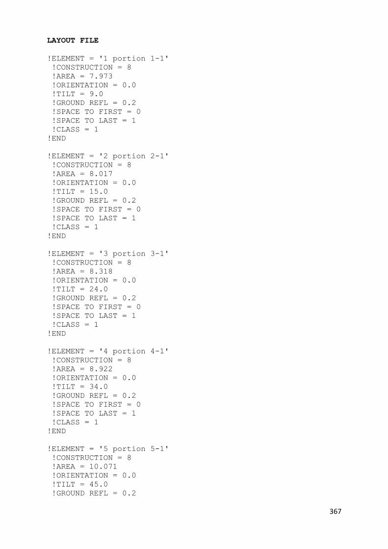
367
LAYOUT FILE
!ELEMENT = '1 portion 1-1'
!CONSTRUCTION = 8
!AREA = 7.973
!ORIENTATION = 0.0
!TILT = 9.0
!GROUND REFL = 0.2
!SPACE TO FIRST = 0
!SPACE TO LAST = 1
!CLASS = 1
!END
!ELEMENT = '2 portion 2-1'
!CONSTRUCTION = 8
!AREA = 8.017
!ORIENTATION = 0.0
!TILT = 15.0
!GROUND REFL = 0.2
!SPACE TO FIRST = 0
!SPACE TO LAST = 1
!CLASS = 1
!END
!ELEMENT = '3 portion 3-1'
!CONSTRUCTION = 8
!AREA = 8.318
!ORIENTATION = 0.0
!TILT = 24.0
!GROUND REFL = 0.2
!SPACE TO FIRST = 0
!SPACE TO LAST = 1
!CLASS = 1
!END
!ELEMENT = '4 portion 4-1'
!CONSTRUCTION = 8
!AREA = 8.922
!ORIENTATION = 0.0
!TILT = 34.0
!GROUND REFL = 0.2
!SPACE TO FIRST = 0
!SPACE TO LAST = 1
!CLASS = 1
!END
!ELEMENT = '5 portion 5-1'
!CONSTRUCTION = 8
!AREA = 10.071
!ORIENTATION = 0.0
!TILT = 45.0
!GROUND REFL = 0.2

368
!SPACE TO FIRST = 0
!SPACE TO LAST = 1
!CLASS = 1
!END
!ELEMENT = '6 portion 6-1'
!CONSTRUCTION = 8
!AREA = 11.766
!ORIENTATION = 0.0
!TILT = 55.0
!GROUND REFL = 0.2
!SPACE TO FIRST = 0
!SPACE TO LAST = 1
!CLASS = 1
!END
!ELEMENT = '7 portion 7-1'
!CONSTRUCTION = 8
!AREA = 14.203
!ORIENTATION = 0.0
!TILT = 64.0
!GROUND REFL = 0.2
!SPACE TO FIRST = 0
!SPACE TO LAST = 1
!CLASS = 1
!END
!ELEMENT = '8 portion 8-1'
!CONSTRUCTION = 8
!AREA = 11.605
!ORIENTATION = 0.0
!TILT = 75.0
!GROUND REFL = 0.2
!SPACE TO FIRST = 0
!SPACE TO LAST = 1
!CLASS = 1
!END
!ELEMENT = '9 portion 9-1'
!CONSTRUCTION = 8
!AREA = 10.683
!ORIENTATION = 0.0
!TILT = 80.0
!GROUND REFL = 0.2
!SPACE TO FIRST = 0
!SPACE TO LAST = 1
!CLASS = 1
!END
!ELEMENT = '10 portion 10-1'
!CONSTRUCTION = 8
!AREA = 13.709

369
!ORIENTATION = 0.0
!TILT = 85.0
!GROUND REFL = 0.2
!SPACE TO FIRST = 0
!SPACE TO LAST = 1
!CLASS = 1
!END
!ELEMENT = '11 portion 1-2'
!CONSTRUCTION = 8
!AREA = 7.973
!ORIENTATION = 45.0
!TILT = 9.0
!GROUND REFL = 0.2
!SPACE TO FIRST = 0
!SPACE TO LAST = 1
!CLASS = 1
!END
!ELEMENT = '12 portion 2-2'
!CONSTRUCTION = 8
!AREA = 8.017
!ORIENTATION = 45.0
!TILT = 15.0
!GROUND REFL = 0.2
!SPACE TO FIRST = 0
!SPACE TO LAST = 1
!CLASS = 1
!END
!ELEMENT = '13 portion 3-2'
!CONSTRUCTION = 8
!AREA = 8.318
!ORIENTATION = 45.0
!TILT = 24.0
!GROUND REFL = 0.2
!SPACE TO FIRST = 0
!SPACE TO LAST = 1
!CLASS = 1
!END
!ELEMENT = '14 portion 4-2'
!CONSTRUCTION = 8
!AREA = 8.922
!ORIENTATION = 45.0
!TILT = 34.0
!GROUND REFL = 0.2
!SPACE TO FIRST = 0
!SPACE TO LAST = 1
!CLASS = 1
!END

370
!ELEMENT = '15 portion 5-2'
!CONSTRUCTION = 8
!AREA = 10.071
!ORIENTATION = 45.0
!TILT = 45.0
!GROUND REFL = 0.2
!SPACE TO FIRST = 0
!SPACE TO LAST = 1
!CLASS = 1
!END
!ELEMENT = '16 portion 6-2'
!CONSTRUCTION = 8
!AREA = 11.766
!ORIENTATION = 45.0
!TILT = 55.0
!GROUND REFL = 0.2
!SPACE TO FIRST = 0
!SPACE TO LAST = 1
!CLASS = 1
!END
!ELEMENT = '17 portion 7-2'
!CONSTRUCTION = 8
!AREA = 14.203
!ORIENTATION = 45.0
!TILT = 64.0
!GROUND REFL = 0.2
!SPACE TO FIRST = 0
!SPACE TO LAST = 1
!CLASS = 1
!END
!ELEMENT = '18 portion 8-2'
!CONSTRUCTION = 8
!AREA = 11.605
!ORIENTATION = 45.0
!TILT = 75.0
!GROUND REFL = 0.2
!SPACE TO FIRST = 0
!SPACE TO LAST = 1
!CLASS = 1
!END
!ELEMENT = '19 portion 9-2'
!CONSTRUCTION = 8
!AREA = 10.683
!ORIENTATION = 45.0
!TILT = 80.0
!GROUND REFL = 0.2
!SPACE TO FIRST = 0
!SPACE TO LAST = 1
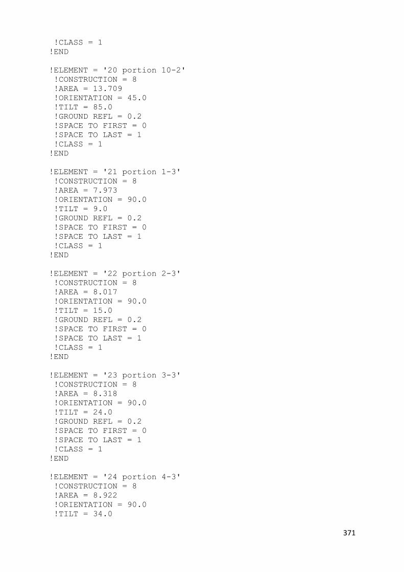
371
!CLASS = 1
!END
!ELEMENT = '20 portion 10-2'
!CONSTRUCTION = 8
!AREA = 13.709
!ORIENTATION = 45.0
!TILT = 85.0
!GROUND REFL = 0.2
!SPACE TO FIRST = 0
!SPACE TO LAST = 1
!CLASS = 1
!END
!ELEMENT = '21 portion 1-3'
!CONSTRUCTION = 8
!AREA = 7.973
!ORIENTATION = 90.0
!TILT = 9.0
!GROUND REFL = 0.2
!SPACE TO FIRST = 0
!SPACE TO LAST = 1
!CLASS = 1
!END
!ELEMENT = '22 portion 2-3'
!CONSTRUCTION = 8
!AREA = 8.017
!ORIENTATION = 90.0
!TILT = 15.0
!GROUND REFL = 0.2
!SPACE TO FIRST = 0
!SPACE TO LAST = 1
!CLASS = 1
!END
!ELEMENT = '23 portion 3-3'
!CONSTRUCTION = 8
!AREA = 8.318
!ORIENTATION = 90.0
!TILT = 24.0
!GROUND REFL = 0.2
!SPACE TO FIRST = 0
!SPACE TO LAST = 1
!CLASS = 1
!END
!ELEMENT = '24 portion 4-3'
!CONSTRUCTION = 8
!AREA = 8.922
!ORIENTATION = 90.0
!TILT = 34.0

372
!GROUND REFL = 0.2
!SPACE TO FIRST = 0
!SPACE TO LAST = 1
!CLASS = 1
!END
!ELEMENT = '25 portion 5-3'
!CONSTRUCTION = 8
!AREA = 10.071
!ORIENTATION = 90.0
!TILT = 45.0
!GROUND REFL = 0.2
!SPACE TO FIRST = 0
!SPACE TO LAST = 1
!CLASS = 1
!END
!ELEMENT = '26 portion 6-3'
!CONSTRUCTION = 8
!AREA = 11.766
!ORIENTATION = 90.0
!TILT = 55.0
!GROUND REFL = 0.2
!SPACE TO FIRST = 0
!SPACE TO LAST = 1
!CLASS = 1
!END
!ELEMENT = '27 portion 7-3'
!CONSTRUCTION = 8
!AREA = 14.203
!ORIENTATION = 90.0
!TILT = 64.0
!GROUND REFL = 0.2
!SPACE TO FIRST = 0
!SPACE TO LAST = 1
!CLASS = 1
!END
!ELEMENT = '28 portion 8-3'
!CONSTRUCTION = 8
!AREA = 11.605
!ORIENTATION = 90.0
!TILT = 75.0
!GROUND REFL = 0.2
!SPACE TO FIRST = 0
!SPACE TO LAST = 1
!CLASS = 1
!END
!ELEMENT = '29 portion 9-3'
!CONSTRUCTION = 8

373
!AREA = 10.683
!ORIENTATION = 90.0
!TILT = 80.0
!GROUND REFL = 0.2
!SPACE TO FIRST = 0
!SPACE TO LAST = 1
!CLASS = 1
!END
!ELEMENT = '30 portion 10-3'
!CONSTRUCTION = 8
!AREA = 13.709
!ORIENTATION = 90.0
!TILT = 85.0
!GROUND REFL = 0.2
!SPACE TO FIRST = 0
!SPACE TO LAST = 1
!CLASS = 1
!END
!ELEMENT = '31 portion 1-4'
!CONSTRUCTION = 8
!AREA = 7.973
!ORIENTATION = 135.0
!TILT = 9.0
!GROUND REFL = 0.2
!SPACE TO FIRST = 0
!SPACE TO LAST = 1
!CLASS = 1
!END
!ELEMENT = '32 portion 2-4'
!CONSTRUCTION = 8
!AREA = 8.017
!ORIENTATION = 135.0
!TILT = 15.0
!GROUND REFL = 0.2
!SPACE TO FIRST = 0
!SPACE TO LAST = 1
!CLASS = 1
!END
!ELEMENT = '33 portion 3-4'
!CONSTRUCTION = 8
!AREA = 8.318
!ORIENTATION = 135.0
!TILT = 24.0
!GROUND REFL = 0.2
!SPACE TO FIRST = 0
!SPACE TO LAST = 1
!CLASS = 1
!END

374
!ELEMENT = '34 portion 4-3'
!CONSTRUCTION = 8
!AREA = 8.922
!ORIENTATION = 135.0
!TILT = 34.0
!GROUND REFL = 0.2
!SPACE TO FIRST = 0
!SPACE TO LAST = 1
!CLASS = 1
!END
!ELEMENT = '35 portion 5-4'
!CONSTRUCTION = 8
!AREA = 10.071
!ORIENTATION = 135.0
!TILT = 45.0
!GROUND REFL = 0.2
!SPACE TO FIRST = 0
!SPACE TO LAST = 1
!CLASS = 1
!END
!ELEMENT = '36 portion 6-4'
!CONSTRUCTION = 8
!AREA = 11.766
!ORIENTATION = 135.0
!TILT = 55.0
!GROUND REFL = 0.2
!SPACE TO FIRST = 0
!SPACE TO LAST = 1
!CLASS = 1
!END
!ELEMENT = '37 portion 7-4'
!CONSTRUCTION = 8
!AREA = 14.203
!ORIENTATION = 135.0
!TILT = 64.0
!GROUND REFL = 0.2
!SPACE TO FIRST = 0
!SPACE TO LAST = 1
!CLASS = 1
!END
!ELEMENT = '38 portion 8-4'
!CONSTRUCTION = 8
!AREA = 11.605
!ORIENTATION = 135.0
!TILT = 75.0
!GROUND REFL = 0.2
!SPACE TO FIRST = 0

375
!SPACE TO LAST = 1
!CLASS = 1
!END
!ELEMENT = '39 portion 9-4'
!CONSTRUCTION = 8
!AREA = 10.683
!ORIENTATION = 135.0
!TILT = 80.0
!GROUND REFL = 0.2
!SPACE TO FIRST = 0
!SPACE TO LAST = 1
!CLASS = 1
!END
!ELEMENT = '40 portion 10-4'
!CONSTRUCTION = 8
!AREA = 13.709
!ORIENTATION = 135.0
!TILT = 85.0
!GROUND REFL = 0.2
!SPACE TO FIRST = 0
!SPACE TO LAST = 1
!CLASS = 1
!END
!ELEMENT = '41 portion 1-5'
!CONSTRUCTION = 8
!AREA = 7.973
!ORIENTATION = 180.0
!TILT = 9.0
!GROUND REFL = 0.2
!SPACE TO FIRST = 0
!SPACE TO LAST = 1
!CLASS = 1
!END
!ELEMENT = '42 portion 2-5'
!CONSTRUCTION = 8
!AREA = 8.017
!ORIENTATION = 180.0
!TILT = 15.0
!GROUND REFL = 0.2
!SPACE TO FIRST = 0
!SPACE TO LAST = 1
!CLASS = 1
!END
!ELEMENT = '43 portion 3-5'
!CONSTRUCTION = 8
!AREA = 8.318
!ORIENTATION = 180.0
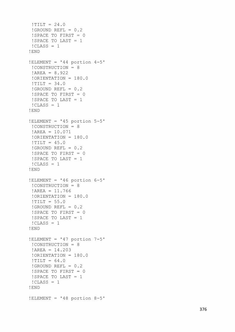
376
!TILT = 24.0
!GROUND REFL = 0.2
!SPACE TO FIRST = 0
!SPACE TO LAST = 1
!CLASS = 1
!END
!ELEMENT = '44 portion 4-5'
!CONSTRUCTION = 8
!AREA = 8.922
!ORIENTATION = 180.0
!TILT = 34.0
!GROUND REFL = 0.2
!SPACE TO FIRST = 0
!SPACE TO LAST = 1
!CLASS = 1
!END
!ELEMENT = '45 portion 5-5'
!CONSTRUCTION = 8
!AREA = 10.071
!ORIENTATION = 180.0
!TILT = 45.0
!GROUND REFL = 0.2
!SPACE TO FIRST = 0
!SPACE TO LAST = 1
!CLASS = 1
!END
!ELEMENT = '46 portion 6-5'
!CONSTRUCTION = 8
!AREA = 11.766
!ORIENTATION = 180.0
!TILT = 55.0
!GROUND REFL = 0.2
!SPACE TO FIRST = 0
!SPACE TO LAST = 1
!CLASS = 1
!END
!ELEMENT = '47 portion 7-5'
!CONSTRUCTION = 8
!AREA = 14.203
!ORIENTATION = 180.0
!TILT = 64.0
!GROUND REFL = 0.2
!SPACE TO FIRST = 0
!SPACE TO LAST = 1
!CLASS = 1
!END
!ELEMENT = '48 portion 8-5'
377
!CONSTRUCTION = 8
!AREA = 11.605
!ORIENTATION = 180.0
!TILT = 75.0
!GROUND REFL = 0.2
!SPACE TO FIRST = 0
!SPACE TO LAST = 1
!CLASS = 1
!END
!ELEMENT = '49 portion 9-5'
!CONSTRUCTION = 8
!AREA = 10.683
!ORIENTATION = 180.0
!TILT = 80.0
!GROUND REFL = 0.2
!SPACE TO FIRST = 0
!SPACE TO LAST = 1
!CLASS = 1
!END
!ELEMENT = '50 portion 10-5'
!CONSTRUCTION = 8
!AREA = 13.709
!ORIENTATION = 180.0
!TILT = 85.0
!GROUND REFL = 0.2
!SPACE TO FIRST = 0
!SPACE TO LAST = 1
!CLASS = 1
!END
!ELEMENT = '51 portion 1-6'
!CONSTRUCTION = 8
!AREA = 7.973
!ORIENTATION = 225.0
!TILT = 9.0
!GROUND REFL = 0.2
!SPACE TO FIRST = 0
!SPACE TO LAST = 1
!CLASS = 1
!END
!ELEMENT = '52 portion 2-6'
!CONSTRUCTION = 8
!AREA = 8.017
!ORIENTATION = 225.0
!TILT = 15.0
!GROUND REFL = 0.2
!SPACE TO FIRST = 0
!SPACE TO LAST = 1
!CLASS = 1

378
!END
!ELEMENT = '53 portion 3-6'
!CONSTRUCTION = 8
!AREA = 8.318
!ORIENTATION = 225.0
!TILT = 24.0
!GROUND REFL = 0.2
!SPACE TO FIRST = 0
!SPACE TO LAST = 1
!CLASS = 1
!END
!ELEMENT = '54 portion 4-6'
!CONSTRUCTION = 8
!AREA = 8.922
!ORIENTATION = 225.0
!TILT = 34.0
!GROUND REFL = 0.2
!SPACE TO FIRST = 0
!SPACE TO LAST = 1
!CLASS = 1
!END
!ELEMENT = '55 portion 5-6'
!CONSTRUCTION = 8
!AREA = 10.071
!ORIENTATION = 225.0
!TILT = 45.0
!GROUND REFL = 0.2
!SPACE TO FIRST = 0
!SPACE TO LAST = 1
!CLASS = 1
!END
!ELEMENT = '56 portion 6-6'
!CONSTRUCTION = 8
!AREA = 11.766
!ORIENTATION = 225.0
!TILT = 55.0
!GROUND REFL = 0.2
!SPACE TO FIRST = 0
!SPACE TO LAST = 1
!CLASS = 1
!END
!ELEMENT = '57 portion 7-6'
!CONSTRUCTION = 8
!AREA = 14.203
!ORIENTATION = 225.0
!TILT = 64.0
!GROUND REFL = 0.2

379
!SPACE TO FIRST = 0
!SPACE TO LAST = 1
!CLASS = 1
!END
!ELEMENT = '58 portion 8-6'
!CONSTRUCTION = 8
!AREA = 11.605
!ORIENTATION = 225.0
!TILT = 75.0
!GROUND REFL = 0.2
!SPACE TO FIRST = 0
!SPACE TO LAST = 1
!CLASS = 1
!END
!ELEMENT = '59 portion 9-6'
!CONSTRUCTION = 8
!AREA = 10.683
!ORIENTATION = 225.0
!TILT = 80.0
!GROUND REFL = 0.2
!SPACE TO FIRST = 0
!SPACE TO LAST = 1
!CLASS = 1
!END
!ELEMENT = '60 portion 10-6'
!CONSTRUCTION = 8
!AREA = 13.709
!ORIENTATION = 225.0
!TILT = 85.0
!GROUND REFL = 0.2
!SPACE TO FIRST = 0
!SPACE TO LAST = 1
!CLASS = 1
!END
!ELEMENT = '61 portion 1-7'
!CONSTRUCTION = 8
!AREA = 7.973
!ORIENTATION = 270.0
!TILT = 9.0
!GROUND REFL = 0.2
!SPACE TO FIRST = 0
!SPACE TO LAST = 1
!CLASS = 1
!END
!ELEMENT = '62 portion 2-7'
!CONSTRUCTION = 8
!AREA = 8.017
380
!ORIENTATION = 270.0
!TILT = 15.0
!GROUND REFL = 0.2
!SPACE TO FIRST = 0
!SPACE TO LAST = 1
!CLASS = 1
!END
!ELEMENT = '63 portion 3-7'
!CONSTRUCTION = 8
!AREA = 8.318
!ORIENTATION = 270.0
!TILT = 24.0
!GROUND REFL = 0.2
!SPACE TO FIRST = 0
!SPACE TO LAST = 1
!CLASS = 1
!END
!ELEMENT = '64 portion 4-7'
!CONSTRUCTION = 8
!AREA = 8.922
!ORIENTATION = 270.0
!TILT = 34.0
!GROUND REFL = 0.2
!SPACE TO FIRST = 0
!SPACE TO LAST = 1
!CLASS = 1
!END
!ELEMENT = '65 portion 5-7'
!CONSTRUCTION = 8
!AREA = 10.071
!ORIENTATION = 270.0
!TILT = 45.0
!GROUND REFL = 0.2
!SPACE TO FIRST = 0
!SPACE TO LAST = 1
!CLASS = 1
!END
!ELEMENT = '66 portion 6-7'
!CONSTRUCTION = 8
!AREA = 11.766
!ORIENTATION = 270.0
!TILT = 55.0
!GROUND REFL = 0.2
!SPACE TO FIRST = 0
!SPACE TO LAST = 1
!CLASS = 1
!END

381
!ELEMENT = '67 portion 7-7'
!CONSTRUCTION = 8
!AREA = 14.203
!ORIENTATION = 270.0
!TILT = 64.0
!GROUND REFL = 0.2
!SPACE TO FIRST = 0
!SPACE TO LAST = 1
!CLASS = 1
!END
!ELEMENT = '68 portion 8-7'
!CONSTRUCTION = 8
!AREA = 11.605
!ORIENTATION = 270.0
!TILT = 75.0
!GROUND REFL = 0.2
!SPACE TO FIRST = 0
!SPACE TO LAST = 1
!CLASS = 1
!END
!ELEMENT = '69 portion 9-7'
!CONSTRUCTION = 8
!AREA = 10.683
!ORIENTATION = 270.0
!TILT = 80.0
!GROUND REFL = 0.2
!SPACE TO FIRST = 0
!SPACE TO LAST = 1
!CLASS = 1
!END
!ELEMENT = '70 portion 10-7'
!CONSTRUCTION = 8
!AREA = 13.709
!ORIENTATION = 270.0
!TILT = 85.0
!GROUND REFL = 0.2
!SPACE TO FIRST = 0
!SPACE TO LAST = 1
!CLASS = 1
!END
!ELEMENT = '71 portion 1-8'
!CONSTRUCTION = 8
!AREA = 7.973
!ORIENTATION = 315.0
!TILT = 9.0
!GROUND REFL = 0.2
!SPACE TO FIRST = 0
!SPACE TO LAST = 1
382
!CLASS = 1
!END
!ELEMENT = '72 portion 2-8'
!CONSTRUCTION = 8
!AREA = 8.017
!ORIENTATION = 315.0
!TILT = 15.0
!GROUND REFL = 0.2
!SPACE TO FIRST = 0
!SPACE TO LAST = 1
!CLASS = 1
!END
!ELEMENT = '73 portion 3-8'
!CONSTRUCTION = 8
!AREA = 8.318
!ORIENTATION = 335.0
!TILT = 24.0
!GROUND REFL = 0.2
!SPACE TO FIRST = 0
!SPACE TO LAST = 1
!CLASS = 1
!END
!ELEMENT = '74 portion 4-8'
!CONSTRUCTION = 8
!AREA = 8.922
!ORIENTATION = 315.0
!TILT = 34.0
!GROUND REFL = 0.2
!SPACE TO FIRST = 0
!SPACE TO LAST = 1
!CLASS = 1
!END
!ELEMENT = '75 portion 5-8'
!CONSTRUCTION = 8
!AREA = 10.071
!ORIENTATION = 315.0
!TILT = 45.0
!GROUND REFL = 0.2
!SPACE TO FIRST = 0
!SPACE TO LAST = 1
!CLASS = 1
!END
!ELEMENT = '76 portion 6-8'
!CONSTRUCTION = 8
!AREA = 11.766
!ORIENTATION = 315.0
!TILT = 55.0

383
!GROUND REFL = 0.2
!SPACE TO FIRST = 0
!SPACE TO LAST = 1
!CLASS = 1
!END
!ELEMENT = '77 portion 7-8'
!CONSTRUCTION = 8
!AREA = 14.203
!ORIENTATION = 315.0
!TILT = 64.0
!GROUND REFL = 0.2
!SPACE TO FIRST = 0
!SPACE TO LAST = 1
!CLASS = 1
!END
!ELEMENT = '78 portion 8-8'
!CONSTRUCTION = 8
!AREA = 11.605
!ORIENTATION = 315.0
!TILT = 75.0
!GROUND REFL = 0.2
!SPACE TO FIRST = 0
!SPACE TO LAST = 1
!CLASS = 1
!END
!ELEMENT = '79 portion 9-8'
!CONSTRUCTION = 8
!AREA = 10.683
!ORIENTATION = 315.0
!TILT = 80.0
!GROUND REFL = 0.2
!SPACE TO FIRST = 0
!SPACE TO LAST = 1
!CLASS = 1
!END
!ELEMENT = '80 portion 10-8'
!CONSTRUCTION = 8
!AREA = 13.709
!ORIENTATION = 315.0
!TILT = 85.0
!GROUND REFL = 0.2
!SPACE TO FIRST = 0
!SPACE TO LAST = 1
!CLASS = 1
!END
!ELEMENT = '113 south wall'
!CONSTRUCTION = 1

384
!AREA = 8.0
!ORIENTATION = 67.0
!TILT = 0.0
!GROUND REFL = 0.2
!SPACE TO FIRST = 0
!SPACE TO LAST = 1
!CLASS = 1
!END
!ELEMENT = '114 east wall'
!CONSTRUCTION = 1
!AREA = 8.0
!ORIENTATION = 157.0
!TILT = 0.0
!GROUND REFL = 0.2
!SPACE TO FIRST = 0
!SPACE TO LAST = 1
!CLASS = 1
!END
!ELEMENT = '115 north wall'
!CONSTRUCTION = 1
!AREA = 8.0
!ORIENTATION = 247.0
!TILT = 0.0
!GROUND REFL = 0.2
!SPACE TO FIRST = 0
!SPACE TO LAST = 1
!CLASS = 1
!END
!ELEMENT = '116 west wall'
!CONSTRUCTION = 1
!AREA = 8.0
!ORIENTATION = 337.0
!TILT = 80.0
!GROUND REFL = 0.2
!SPACE TO FIRST = 0
!SPACE TO LAST = 1
!CLASS = 1
!END
!ELEMENT = '117 south windows'
!CONSTRUCTION = 2
!AREA = 10.0
!ORIENTATION = 67.0
!TILT = 0.0
!GROUND REFL = 0.2
!SPACE TO FIRST = 0
!SPACE TO LAST = 1
!PATCH TO #29 FIRST = 1
!SHADING = 'NONE'
385
!WINDOW TYPE = '6MMFLOAT'
!CLASS = 2
!END
!ELEMENT = '118 east windows'
!CONSTRUCTION = 2
!AREA = 10.0
!ORIENTATION = 157.0
!TILT = 0.0
!GROUND REFL = 0.2
!SPACE TO FIRST = 0
!SPACE TO LAST = 1
!PATCH TO #29 FIRST = 1
!SHADING = 'NONE'
!WINDOW TYPE = '6MMFLOAT'
!CLASS = 2
!END
!ELEMENT = '119 north windows'
!CONSTRUCTION = 2
!AREA = 10.0
!ORIENTATION = 247.0
!TILT = 0.0
!GROUND REFL = 0.2
!SPACE TO FIRST = 0
!SPACE TO LAST = 1
!PATCH TO #29 FIRST = 1
!SHADING = 'NONE'
!WINDOW TYPE = '6MMFLOAT'
!CLASS = 2
!END
!ELEMENT = '120 west windows'
!CONSTRUCTION = 2
!AREA = 10.0
!ORIENTATION = 337.0
!TILT = 0.0
!GROUND REFL = 0.2
!SPACE TO FIRST = 0
!SPACE TO LAST = 1
!PATCH TO #29 FIRST = 1
!SHADING = 'NONE'
!WINDOW TYPE = '6MMFLOAT'
!CLASS = 2
!END

386
APPENDIX D -PUBLICATION
PROCEEDINGS OF THE 3RD CIB INTERNATIONAL CONFERENCE ON SMART AND SUSTAINABLE BUILT ENVIRONMENT SASBE 2009.

387

388

389

390
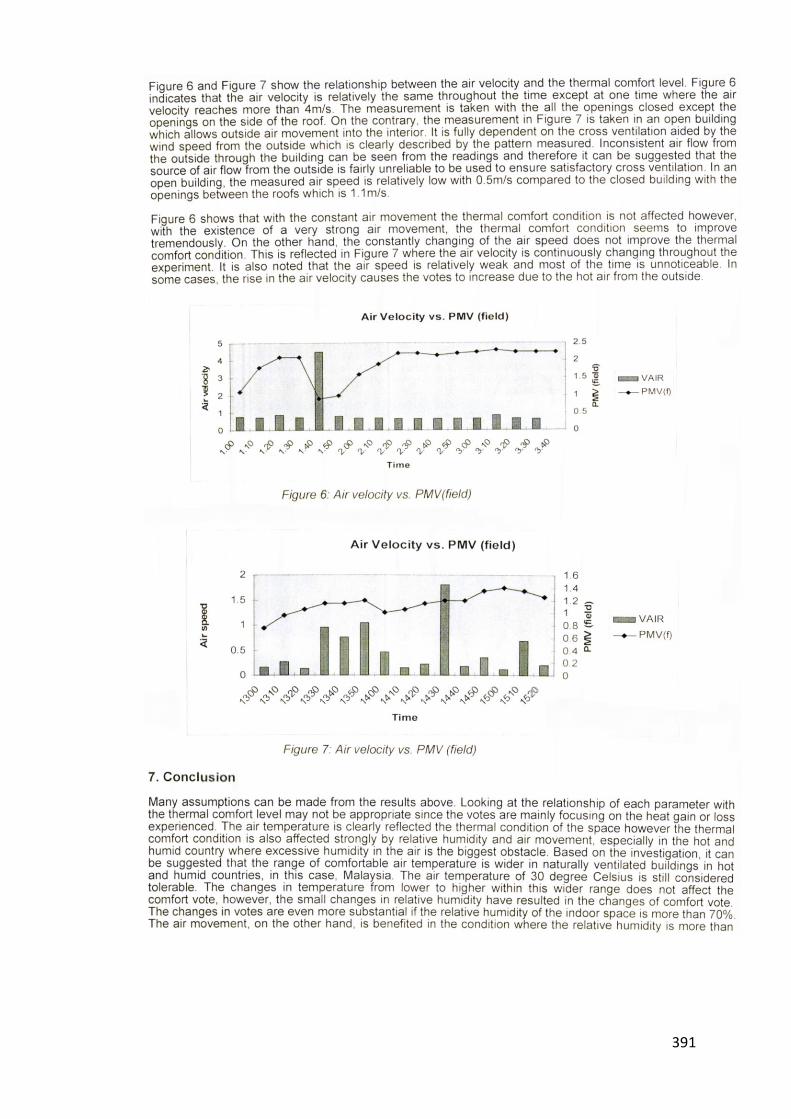
391

392