Cary Grant, Shaving and the Uninhabitable Dream - Architectural

2003 INTERNATIONAL RESIDENTIAL CODE� 215
CHAPTER 8
ROOF-CEILING CONSTRUCTION
SECTION R801GENERAL
R801.1 Application. The provisions of this chapter shall con-trol the design and construction of the roof-ceiling system forall buildings.
R801.2 Requirements.Roof and ceiling construction shall becapable of accommodating all loads imposed according to Sec-tionR301 and of transmitting the resulting loads to the support-ing structural elements.
R801.3 Roof drainage. In areas where expansive or collaps-ible soils are known to exist, all dwellings shall have a con-trolledmethodofwater disposal fromroofs thatwill collect anddischarge all roof drainage to the ground surface at least 5 feet(1524 mm) from foundation walls or to an approved drainagesystem.
SECTION R802WOOD ROOF FRAMING
R802.1 Identification. Load-bearing dimension lumber forrafters, trusses and ceiling joists shall be identified by a grademarkof a lumbergradingor inspection agency thathasbeenap-proved by an accreditation body that complies with DOC PS20. In lieuof agrademark, a certificate of inspection issued byalumber grading or inspection agencymeeting the requirementsof this section shall be accepted.
R802.1.1 Blocking. Blocking shall be a minimum of utilitygrade lumber.
R802.1.2 End-jointed lumber.Approved end-jointed lum-ber identified bya grademark conforming to SectionR802.1may be used interchangeably with solid-sawn members ofthe same species and grade.
R802.1.3 Fire-retardant-treated wood. Fire-retardant-treatedwood is anywood productwhich,when impregnatedwith chemicals by a pressure process or other means duringmanufacture, shall have, when tested in accordance withASTM E84, a listed flame spread index of 25 or less andshow no evidence of significant progressive combustionwhen the test is continued for an additional 20-minute peri-od. In addition, the flame front shall not progress more than10.5 feet (3200 mm) beyond the center line of the burners atany time during the test.
R802.1.3.1 Labeling. Fire-retardant-treated lumber andwood structural panels shall be labeled. The label shallcontain:
1. The identification mark of an approved agency inaccordancewithSection1703.5of the Internation-al Building Code.
2. Identification of the treating manufacturer.3. The name of the fire-retardant treatment.4. The species of wood treated.5. Flame spread and smoke developed rating.6. Method drying after treatment.7. Conformancewith appropriate standards in accor-
dance with Sections R802.1.3.2 throughR802.1.3.5.
8. For FRTW exposed to weather, damp or wet loca-tion, thewords�No increase in the listed classifica-tion when subjected to the Standard Rain Test�(ASTM D2898).
R802.1.3.2 Strength adjustments.Design values for un-treated lumber and wood structural panels as specified inSection R802.1, shall be adjusted for fire retardant-treatedwood.Adjustments to design values shall be basedupon an approved method of investigation which takesinto consideration the effects of the anticipated tempera-ture and humidity to which the fire-retardant-treatedwoodwill be subjected, the type of treatment and redryingprocedures.
R802.1.3.2.1 Wood structural panels. The effect oftreatment and the method of redrying after treatment,and exposure to high temperatures and high humiditieson the flexure properties of fire-retardant-treated soft-wood plywood shall be determined in accordance withASTM D 5516. The test data developed by ASTM D5516 shall be used to develop adjustment factors,maxi-mum loads and spans, or both for untreated plywooddesign values in accordance with ASTMD 6305. Eachmanufacturer shall publish the allowable maximumloads and spans for service as floor and roof sheathingfor their treatment.
R802.1.3.2.2 Lumber. For each species of woodtreated the effect of the treatment and the method ofredrying after treatment and exposure to high tempera-tures and high humidities on the allowable design prop-erties of fire-retardant-treated lumber shall be deter-mined in accordancewith ASTMD5664. The test datadeveloped by ASTM D 5664 shall be used to developmodification factors for use at or near room tempera-ture and at elevated temperatures and humidity in ac-cordance with an approved method of investigation.Each manufacturer shall publish the modification fac-tors for service at temperatures of not less than 80�F(26.7�C) and for roof framing. The roof framingmodi-fication factors shall take into consideration the clima-tological location.
R802.1.3.3 Exposure to weather.Where fire-retardant-treated wood is exposed to weather, or damp or wet loca-tions, it shall be identified as �Exterior� to indicate there is

ROOF-CEILING CONSTRUCTION
216 2003 INTERNATIONAL RESIDENTIAL CODE�
no increase in the listed flamespread index as defined inSection R802.1.3 when subjected to ASTM D 2898.
R802.1.3.4 Interior applications. Interior fire-retardant-treated wood shall have a moisture content of not over 28percent when tested in accordance with ASTM D 3201procedures at 92 percent relative humidity. Interior fire-retardant-treated wood shall be tested in accordance withSectionR802.1.3.2.1 or R802.1.3.2.2. Interior fire-retardant-treated wood designated as Type A shall betested in accordance with the provisions of this section.
R802.1.3.5 Moisture content. Fire-retardant-treatedwood shall be dried to a moisture content of 19 percent orless for lumber and 15 percent or less for wood structuralpanels before use. For wood kiln dried after treatment(KDAT) the kiln temperatures shall not exceed those usedin kiln drying the lumber and plywood submitted for thetests described in Section R802.1.3.2.1for plywood andR802.1.3.2.2 for lumber.
R802.1.4 Structural glued laminated timbers.Glued lam-inated timbers shall be manufactured and identified as re-quired in AITC A190.1 and ASTM D3737.
R802.2 Design and construction. Roof-ceilings shall be de-signed and constructed in accordance with the provisions ofthis chapter and Figures R606.10(1), R606.10(2) andR606.10(3) or in accordancewithAFPA/NDS. Components ofroof-ceilings shall be fastened in accordance with TableR602.3(1).
R802.3 Framing details. Rafters shall be framed to ridgeboard or to each other with a gusset plate as a tie. Ridge boardshall be at least 1-inch (25.4 mm) nominal thickness and notless in depth than the cut end of the rafter.At all valleys andhipsthere shall be a valley or hip rafter not less than 2-inch (51mm)nominal thickness and not less in depth than the cut end of therafter. Hip and valley rafters shall be supported at the ridge by abrace to a bearing partition or be designed to carry and distrib-ute the specific load at that point. Where the roof pitch is lessthan three units vertical in 12 units horizontal (25-percentslope), structural members that support rafters and ceilingjoists, such as ridge beams, hips and valleys, shall be designedas beams.
R802.3.1 Ceiling joist and rafter connections. Ceilingjoists and rafters shall be nailed to each other in accordancewith Tables R602.3(1) and R802.5.1(9), and the assemblyshall be nailed to the top wall plate in accordance with TableR602.3(1). Ceiling joists shall be continuous or securelyjoined where they meet over interior partitions and nailed toadjacent rafters to provide a continuous tie across the build-ing when such joists are parallel to the rafters.
Where ceiling joists are not parallel to rafters, subflooringor metal straps attached to the ends of the rafters shall beinstalled in a manner to provide a continuous tie across thebuilding, or rafters shall be tied to 1-inch by 4-inch (25.4mmby102mm) (nominal)minimum-size crossties.Theconnec-tions shall be in accordancewith TableR602.3(1) or connec-tions of equivalent capacities shall be provided.Where ceil-ing joists or rafter ties are not provided at the top plate, the
ridge formed by these rafters shall also be supported by agirder designed in accordance with accepted engineeringpractice.
Rafter ties shall be spaced notmore than 4 feet (1219mm)on center.
R802.3.2 Ceiling joists lapped. Ends of ceiling joists shallbe lapped a minimum of 3 inches (76 mm) or butted overbearing partitions or beams and toenailed to the bearingmember.Whenceiling joists areused toprovide resistance torafter thrust, lapped joists shall be nailed together in accor-dancewith TableR602.3(1) and butted joists shall be tied to-gether in a manner to resist such thrust.
R802.4 Allowable ceiling joist spans. Spans for ceiling joistsshall be in accordance with Tables R802.4(1) and R802.4(2).For other grades and species and for other loading conditions,refer to the AF&PA Span Tables for Joists and Rafters.
R802.5 Allowable rafter spans. Spans for rafters shall be inaccordance with Tables R802.5.1(1) through R802.5.1(8). Forother grades and species and for other loading conditions, referto the AF&PA Span Tables for Joists and Rafters. The span ofeach rafter shall bemeasured along the horizontal projection ofthe rafter.
R802.5.1 Purlins. Purlins are permitted to be installed to re-duce the span of rafters as shown in FigureR802.5.1. Purlinsshall be sized no less than the required size of the rafters thatthey support. Purlins shall be continuous and shall be sup-ported by 2-inch by 4-inch (51 mm by 102 mm) bracesinstalled to bearing walls at a slope not less than 45 degreesfrom the horizontal. The braces shall be spaced not morethan 4 feet (1219 mm) on center and the unbraced length ofbraces shall not exceed 8 feet (2438 mm).
R802.6 Bearing. The ends of each rafter or ceiling joist shallhave not less than 11/2 inches (38 mm) of bearing on wood ormetal and not less than 3 inches (76 mm) on masonry or con-crete.
R802.6.1 Finished ceiling material. If the finished ceilingmaterial is installed on the ceiling prior to the attachment ofthe ceiling to the walls, such as in construction at a factory, acompression strip of the same thickness as the finish ceilingmaterial shall be installed directly above the top plate ofbearingwalls if the compressive strength of the finish ceilingmaterial is less than the loads it will be required towithstand.The compression strip shall cover the entire length of suchtop plate and shall be at least one-half the width of the topplate. It shall be ofmaterial capable of transmitting the loadstransferred through it.
R802.7 Cutting and notching. Structural roof members shallnot be cut, bored or notched in excess of the limitations speci-fied in this section.
R802.7.1 Sawn lumber.Notches in solid lumber joists, raf-ters and beams shall not exceed one-sixth of the depth of themember, shall not be longer than one-thirdof thedepth of themember and shall not be located in the middle one-third ofthe span. Notches at the ends of themember shall not exceedone-fourth the depth of the member. The tension side of

ROOF-CEILING CONSTRUCTION
2003 INTERNATIONAL RESIDENTIAL CODE� 217
members 4 inches (102mm) or greater in nominal thicknessshall not be notched except at the ends of the members. Thediameter of the holes bored or cut intomembers shall not ex-ceed one-third the depth of the member. Holes shall not becloser than2 inches (51mm) to the topor bottomof themem-ber, or to any other hole located in the member. Where themember is also notched, the hole shall not be closer than 2inches (51 mm) to the notch.
Exception: Notches on cantilevered portions of raftersare permitted provided the dimension of the remainingportion of the rafter is not less than 4-inch nominal (102mm) and the length of the cantilever does not exceed 24inches (610 mm).
R802.7.2 Engineered wood products. Cuts, notches andholes bored in laminated veneer lumber, glue-laminatedmembers or I-joists are not permitted unless the effect ofsuch penetrations are specifically considered in the designofthe member.
R802.8 Lateral support. Rafters and ceiling joists having adepth-to-thickness ratio exceeding 5 to 1 based on nominal di-mensions shall be provided with lateral support at points ofbearing to prevent rotation.
R802.8.1 Bridging. Rafters and ceiling joists having adepth-to-thickness ratio exceeding 6 to 1 based on nominaldimensions shall be supported laterally by solid blocking,di-agonal bridging (wood or metal) or a continuous 1-inch by3-inch (25.4mmby 76mm)wood strip nailed across the raf-ters or ceiling joists at intervals not exceeding 8 feet (2438mm).
R802.9 Framing of openings. Openings in roof and ceilingframing shall be framed with header and trimmer joists. Whenthe header joist span does not exceed 4 feet (1219 mm), theheader joistmay be a singlemember the same size as the ceilingjoist or rafter. Single trimmer joists may be used to carry asingle header joist that is located within 3 feet (914 mm) of thetrimmer joist bearing. When the header joist span exceeds 4feet (1219 mm), the trimmer joists and the header joist shall bedoubled and of sufficient cross section to support the ceilingjoists or rafter framing into the header. Approved hangers shallbe used for the header joist to trimmer joist connections whenthe header joist span exceeds 6 feet (1829mm). Tail joists over12 feet (3658 mm) long shall be supported at the header byframing anchors or on ledger strips not less than 2 inches by 2inches (51 mm by 51 mm).
R802.10 Wood trusses.
R802.10.1 Truss design drawings. Truss design drawings,prepared in conformance with Section R802.10.1, shall beprovided to the building official and approvedprior to instal-lation. Truss design drawings shall include, at a minimum,the information specified below. Truss design drawing shallbe providedwith the shipment of trusses delivered to the job-site.
1. Slope or depth, span and spacing.
2. Location of all joints.
3. Required bearing widths.
4. Design loads as applicable.
4.1. Top chord live load (including snowloads).
4.2. Top chord dead load.
4.3. Bottom chord live load.
4.4. Bottom chord dead load.
4.5. Concentrated loads and their points of ap-plication.
4.6. Controlling wind and earthquake loads.
5. Adjustments to lumber and joint connector designvalues for conditions of use.
6. Each reaction force and direction.
7. Joint connector type and description (e.g., size,thickness or gauge) and the dimensioned locationof each joint connector except where symmet-rically located relative to the joint interface.
8. Lumber size, species and grade for each member.
9. Connection requirements for:
9.1. Truss to truss girder.
9.2. Truss ply to ply.
9.3. Field splices.
10. Calculated deflection ratio and/or maximum de-scription for live and total load.
11. Maximum axial compression forces in the trussmembers to enable the building designer to designthe size, connections and anchorage of the perma-nent continuous lateral bracing. Forces shall beshown on the truss design drawing or on supple-mental documents.
12. Required permanent truss member bracinglocation.
R802.10.2 Design.Wood trusses shall be designed in accor-dance with accepted engineering practice. The design andmanufacture of metal plate connected wood trusses shallcomplywithANSI/TPI 1. The truss design drawings shall beprepared by a registered professional where required by thestatutes of the jurisdiction in which the project is to beconstructed in accordance with Section R106.1.
R802.10.3 Bracing. Trusses shall be braced to prevent rota-tion and provide lateral stability in accordance with the re-quirements specified in the construction documents for thebuilding and on the individual truss design drawings. In theabsence of specific bracing requirements, trusses shall bebraced in accordance with TPI/HIB.
R802.10.4 Alterations to trusses. Truss members shall notbe cut, notched, drilled, spliced or otherwise altered in anywaywithout the approval of a registereddesignprofessional.Alterations resulting in the addition of load (e.g., HVACequipment, water heater) that exceeds the design load for thetruss shall not be permittedwithout verification that the trussis capable of supporting such additional loading.

ROOF-CEILING CONSTRUCTION
218 2003 INTERNATIONAL RESIDENTIAL CODE�
TABLE R802.4(1)CEILING JOIST SPANS FOR COMMON LUMBER SPECIES
(Uninhabitable attics without storage, live load = 10 psf, L/� = 240)
DEAD LOAD = 5 psf
2x4 2x6 2x8 2x10
CEILING JOIST SPACINGMaximum ceiling joist spans
CEILING JOIST SPACING(inches) SPECIES AND GRADE (feet - inches) (feet - inches) (feet - inches) (feet - inches)
12
Douglas fir-larch SSDouglas fir-larch #1Douglas fir-larch #2Douglas fir-larch #3Hem-fir SSHem-fir #1Hem-fir #2Hem-fir #3Southern pine SSSouthern pine #1Southern pine #2Southern pine #3Spruce-pine-fir SSSpruce-pine-fir #1Spruce-pine-fir #2Spruce-pine-fir #3
13-212-812-510-1012-512-211-710-1012-1112-812-511-612-211-1011-1010-10
20-819-1119-615-1019-619-118-215-1020-319-1119-617-019-118-818-815-10
Note aNote a25-820-125-825-224-020-1
Note aNote a25-821-825-224-724-720-1
Note aNote aNote a24-6
Note aNote aNote a24-6
Note aNote aNote a25-7
Note aNote aNote a24-6
16
Douglas fir-larch SSDouglas fir-larch #1Douglas fir-larch #2Douglas fir-larch #3Hem-fir SSHem-fir #1Hem-fir #2Hem-fir #3Southern pine SSSouthern pine #1Southern pine #2Southern pine #3Spruce-pine-fir SSSpruce-pine-fir #1Spruce-pine-fir #2Spruce-pine-fir #3
11-1111-611-39-511-311-010-69-511-911-611-310-011-010-910-99-5
18-918-117-813-917-817-416-613-918-518-117-814-917-416-1116-1113-9
24-823-1023-017-523-422-1021-917-524-323-123-418-922-1022- 422- 417-5
Note aNote aNote a21-3
Note aNote aNote a21-3
Note aNote aNote a22- 2Note aNote aNote a21-3
19.2
Douglas fir-larch SSDouglas fir-larch #1Douglas fir-larch #2Douglas fir-larch #3Hem-fir SSHem-fir #1Hem-fir #2Hem-fir #3Southern -pine SSSouthern pine #1Southern pine #2Southern pine #3Spruce-pine-fir SSSpruce-pine-fir #1Spruce-pine-fir #2Spruce-pine-fir #3
11-310-1010-78-710-710-49-118-711-010-1010-79-110-410-210-28-7
17-817-016-712-616-816-415-712-617-417-016-813-616-415-1115-1112-6
23-322-521-015-1021-1121-620-615-1022-1022-521-1117-221-621-021-015-10
Note aNote a25-819-5
Note aNote a25-319-5
Note aNote aNote a20-3
Note a25-825-819-5
(continued)

ROOF-CEILING CONSTRUCTION
2003 INTERNATIONAL RESIDENTIAL CODE� 219
TABLE R802.4(1)�continuedCEILING JOIST SPANS FOR COMMON LUMBER SPECIES
(Uninhabitable attics without storage, live load = 10 psf, L/� = 240)
DEAD LOAD = 5 psf
2x4 2x6 2x8 2x10
CEILING JOIST SPACINGMaximum ceiling joist spans
CEILING JOIST SPACING(inches) SPECIES AND GRADE (feet - inches) (feet - inches) (feet - inches) (feet - inches)
24
Douglas fir-larch SSDouglas fir-larch #1Douglas fir-larch #2Douglas fir-larch #3Hem-fir SSHem-fir #1Hem-fir #2Hem-fir #3Southern pine SSSouthern pine #1Southern pine #2Southern pine #3Spruce-pine-fir SSSpruce-pine-fir #1Spruce-pine-fir #2Spruce-pine-fir #3
10-510-09-107-89-109-89-27-810-310-09-108-29-89-59-57-8
16-415-914-1011-215-615-214-511-216-115-915-612-015-214-914-911-2
21-720-118-914-220-519-718-614-221-220-1020-115-419-1118-918-914-2
Note a24-622-1117-4
Note a23-1122-717-4
Note aNote a23-1118-125-522-1122-1117-4
Check sources for availability of lumber in lengths greater than 20 feet.For SI: 1 inch = 25.4 mm, 1 foot = 304.8 mm, 1 pound per square foot = 0.0479 kN/m2.a. Span exceeds 26 feet in length.
ROOF-CEILING CONSTRUCTION
220 2003 INTERNATIONAL RESIDENTIAL CODE�
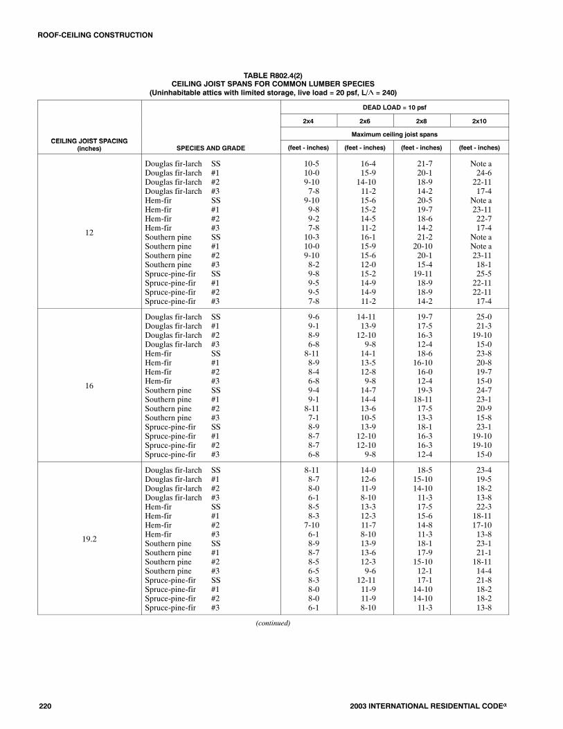
TABLE R802.4(2)CEILING JOIST SPANS FOR COMMON LUMBER SPECIES
(Uninhabitable attics with limited storage, live load = 20 psf, L/� = 240)
DEAD LOAD = 10 psf
2x4 2x6 2x8 2x10
CEILING JOIST SPACINGMaximum ceiling joist spans
CEILING JOIST SPACING(inches) SPECIES AND GRADE (feet - inches) (feet - inches) (feet - inches) (feet - inches)
12
Douglas fir-larch SSDouglas fir-larch #1Douglas fir-larch #2Douglas fir-larch #3Hem-fir SSHem-fir #1Hem-fir #2Hem-fir #3Southern pine SSSouthern pine #1Southern pine #2Southern pine #3Spruce-pine-fir SSSpruce-pine-fir #1Spruce-pine-fir #2Spruce-pine-fir #3
10-510-09-107-89-109-89-27-810-310-09-108-29-89-59-57-8
16-415-914-1011-215-615-214-511-216-115-915-612-015-214-914-911-2
21-720-118-914-220-519-718-614-221-220-1020-115-419-1118-918-914-2
Note a24-622-1117-4
Note a23-1122-717-4
Note aNote a23-1118-125-522-1122-1117-4
16
Douglas fir-larch SSDouglas fir-larch #1Douglas fir-larch #2Douglas fir-larch #3Hem-fir SSHem-fir #1Hem-fir #2Hem-fir #3Southern pine SSSouthern pine #1Southern pine #2Southern pine #3Spruce-pine-fir SSSpruce-pine-fir #1Spruce-pine-fir #2Spruce-pine-fir #3
9-69-18-96-88-118-98-46-89-49-18-117-18-98-78-76-8
14-1113-912-109-814-113-512-89-814-714-413-610-513-912-1012-109-8
19-717-516-312-418-616-1016-012-419-318-1117-513-318-116-316-312-4
25-021-319-1015-023-820-819-715-024-723-120-915-823-119-1019-1015-0
19.2
Douglas fir-larch SSDouglas fir-larch #1Douglas fir-larch #2Douglas fir-larch #3Hem-fir SSHem-fir #1Hem-fir #2Hem-fir #3Southern pine SSSouthern pine #1Southern pine #2Southern pine #3Spruce-pine-fir SSSpruce-pine-fir #1Spruce-pine-fir #2Spruce-pine-fir #3
8-118-78-06-18-58-37-106-18-98-78-56-58-38-08-06-1
14-012-611-98-1013-312-311-78-1013-913-612-39-6
12-1111-911-98-10
18-515-1014-1011-317-515-614-811-318-117-915-1012-117-114-1014-1011-3
23-419-518-213-822-318-1117-1013-823-121-118-1114-421-818-218-213-8
(continued)

ROOF-CEILING CONSTRUCTION
2003 INTERNATIONAL RESIDENTIAL CODE� 221
TABLE R802.4(2)�continuedCEILING JOIST SPANS FOR COMMON LUMBER SPECIES
(Uninhabitable attics with limited storage, live load = 20 psf, L/� = 240)
DEAD LOAD = 10 psf
2x4 2x6 2x8 2x10
CEILING JOIST SPACINGMaximum Ceiling Joist Spans
CEILING JOIST SPACING(inches) SPECIES AND GRADE (feet - inches) (feet - inches) (feet - inches) (feet - inches)
24
Douglas fir-larch SSDouglas fir-larch #1Douglas fir-larch #2Douglas fir-larch #3Hem-fir SSHem-fir #1Hem-fir #2Hem-fir #3Southern pine SSSouthern pine #1Southern pine #2Southern pine #3Spruce-pine-fir SSSpruce-pine-fir #1Spruce-pine-fir #2Spruce-pine-fir #3
8-37-87-25-57-107-67-15-58-18-07-85-97-87-27-25-5
13-011-210-67-1112-310-1110-47-1112-912-611-08-612-010-610-67-11
17-114-213-310-016-213-1013-110-016-1015-1014-210-1015-1013-313-310-0
20-1117-416-312-320-616-1116-012-321-618-1016-1112-1019-516-316-312-3
Check sources for availability of lumber in lengths greater than 20 feet.For SI: 1 inch = 25.4 mm, 1 foot = 304.8 mm, 1 pound per square foot = 0.0479 kN/m2.a. Span exceeds 26 feet in length

ROOF-CEILING CONSTRUCTION
222 2003 INTERNATIONAL RESIDENTIAL CODE�
TABLE R802.5.1(1)RAFTER SPANS FOR COMMON LUMBER SPECIES
(Roof live load=20 psf, ceiling not attached to rafters, L/�=180)
DEAD LOAD = 10 psf DEAD LOAD = 20 psf
2x4 2x6 2x8 2x10 2x12 2x4 2x6 2x8 2x10 2x12
RAFTERMaximum rafter spansa
RAFTERSPACING(inches) SPECIES AND GRADE
(feet -inches)
(feet -inches)
(feet -inches)
(feet -inches)
(feet -inches)
(feet -inches)
(feet -inches)
(feet -inches)
(feet -inches)
(feet -inches)
12
Douglas fir-larch SSDouglas fir-larch #1Douglas fir-larch #2Douglas fir-larch #3Hem-fir SSHem-fir #1Hem-fir #2Hem-fir #3Southern pine SSSouthern pine #1Southern pine #2Southern pine #3Spruce-pine-fir SSSpruce-pine-fir #1Spruce-pine-fir #2Spruce-pine-fir #3
11-611-110-108-7
10-1010-710-18-711-311-110-109-110-710-410-48-7
18-017-416-712-617-016-815-1112-617-817-417-013-616-816-316-312-6
23-922-521-015-1022-521-1020-815-1023-422-1122-517-221-1121-021-015-10
Note bNote b25-819-5
Note bNote b25-319-5
Note bNote bNote b20-3
Note b25-825-819-5
Note bNote bNote b22-6
Note bNote bNote b22-6
Note bNote bNote b24-1
Note bNote bNote b22-6
11-610-69-107-5
10-1010-39-87-511-311-110-67-1110-79-109-107-5
18-015-414-410-1017-014-1114-210-1017-817-315-111-816-814-414-410-10
23-519-518-213-922-518-1117-1113-923-421-919-514-1021-918-218-213-9
Note b23-922-316-9
Note b23-221-1116-9
Note b25-1023-217-6
Note b22-322-316-9
Note bNote b25-919-6
Note bNote b25-519-6
Note bNote bNote b20-11Note b25-925-919-6
16
Douglas fir-larch SSDouglas fir-larch #1Douglas fir-larch #2Douglas fir-larch #3Hem-fir SSHem-fir #1Hem-fir #2Hem-fir #3Southern pine SSSouthern pine #1Southern pine #2Southern pine #3Spruce-pine-fir SSSpruce-pine-fir #1Spruce-pine-fir #2Spruce-pine-fir #3
10-510-09-107-59-109-89-27-510-310-09-107-119-89-59-57-5
16-415-414-410-1015-614-1114-210-1016-115-915-111-815-214-414-410-10
21-719-518-213-920-518-1117-1113-921-220-1019-514-1019-1118-218-213-9
Note b23-922-316-9
Note b23-221-1116-9
Note b25-1023-217-625-522-322-316-9
Note bNote b25-919-6
Note bNote b25-519-6
Note bNote bNote b20-11Note b25-925-919-6
10-59-18-66-59-108-108-56-510-310-09-16-109-88-68-66-5
16-013-312-59-515-612-1112-39-516-115-013-010-114-1012-512-59-5
20-316-1015-911-1119-1116-515-611-1121-218-1016-1012-1018-1015-915-911-11
24-920-719-314-624-420-018-1114-6
Note b22-420-115-223-019-319-314-6
Note b23-1022-416-10Note b23-322-016-10Note bNote b23-718-1
Note b22-422-416-10
19.2
Douglas fir-larch SSDouglas fir-larch #1Douglas fir-larch #2Douglas fir-larch #3Hem-fir SSHem-fir #1Hem-fir #2Hem-fir #3Southern pine SSSouthern pine #1Southern pine #2Southern pine #3Spruce-pine-fir SSSpruce-pine-fir #1Spruce-pine-fir #2Spruce-pine-fir #3
9-109-58-116-99-39-18-86-99-89-59-37-39-18-108-106-9
15-514-013-19-1114-713-812-119-1115-214-1013-910-814-313-113-19-11
20-417-916-712-719-217-416-412-719-1119-717-913-718-916-716-712-7
25-1121-820-315-424-621-120-015-425-523-721-216-023-1120-320-315-4
Note b25-223-617-9
Note b24-623-217-9
Note bNote b24-1019-1
Note b23-623-617-9
9-108-47-95-109-38-17-85-109-89-38-46-39-17-97-95-10
14-712-211-48-714-411-1011-28-715-213-811-119-313-711-411-48-7
18-615-414-410-1018-215-014-210-1019-1117-215-411-917-214-414-410-10
22-718-917-713-322-318-417-413-325-520-518-413-1021-017-717-713-3
Note b21- 920- 415- 525- 921- 320- 115- 5Note b24- 421- 616- 624- 420- 420- 415- 5
(continued)

ROOF-CEILING CONSTRUCTION
2003 INTERNATIONAL RESIDENTIAL CODE� 223
TABLE R802.5.1(1)�continuedRAFTER SPANS FOR COMMON LUMBER SPECIES
(Roof live load=20 psf, ceiling not attached to rafters, L/�=180)
DEAD LOAD = 10 psf DEAD LOAD = 20 psf
2x4 2x6 2x8 2x10 2x12 2x4 2x6 2x8 2x10 2x12
RAFTERMaximum rafter spansa
RAFTERSPACING(inches) SPECIES AND GRADE
(feet -inches)
(feet -inches)
(feet -inches)
(feet -inches)
(feet -inches)
(feet -inches)
(feet -inches)
(feet -inches)
(feet -inches)
(feet -inches)
24
Douglas fir-larch SSDouglas fir-larch #1Douglas fir-larch #2Douglas fir-larch #3Hem-fir SSHem-fir #1Hem-fir #2Hem-fir #3Southern pine SSSouthern pine #1Southern pine #2Southern pine #3Spruce-pine-fir SSSpruce-pine-fir #1Spruce-pine-fir #2Spruce-pine-fir #3
9-18-78-06-18-78-47-116-18-118-98-76-58-58-08-06-1
14-412-611-98-1013-612-311-78-1014-113-912-39-613-311-911-98-10
18-1015-1014-1011-317-1015-614-811-318-617-915-1012-117-514-1014-1011-3
23-419-518-213-822-918-1117-1013-823-821-118-1114-421-818-218-213-8
Note b22-621-015-11Note b21-1120-915-11Note b25-222-217-125-221-021-015-11
8-117-56-115-38-77-36-105-38-118-37-55-78-46-116-115-3
13-110-1010-27-8
12-1010-710-07-814-112-310-88-312-210-210-27-8
16-713-912-109-916-313-512-89-918-615-413-910-615-412-1012-109-9
20-316-915-811-1019-1016-415-611-1022-1118-316-512-518-915-815-811-10
23-519-618-313-923-019-017-1113-9
Note b21-919-314-921-918-318-313-9
Check sources for availability of lumber in lengths greater than 20 feet.
For SI: 1 inch = 25.4 mm, 1 foot = 304.8 mm, 1 pound per square foot = 0.0479 kN/m2.a.The tabulated rafter spans assume that ceiling joists are located at thebottomof theattic spaceor that someothermethodof resisting theoutwardpushof the rafterson the bearing walls, such as rafter ties, is provided at that location.When ceiling joists or rafter ties are located higher in the attic space, the rafter spans shall bemultiplied by the factors given below:
HC/HR Rafter Span Adjustment Factor
2/3 or greater 0.50
1/2 0.58
1/3 0.67
1/4 0.76
1/5 0.83
1/6 0.90
1/7.5 and less 1.00
where: HC = Height of ceiling joists or rafter ties measured vertically above the top of the rafter support walls.
HR = Height of roof ridge measured vertically above the top of the rafter support walls.
b. Span exceeds 26 feet in length.

ROOF-CEILING CONSTRUCTION
224 2003 INTERNATIONAL RESIDENTIAL CODE�
TABLE R802.5.1(2)RAFTER SPANS FOR COMMON LUMBER SPECIES
(Roof live load=20 psf, ceiling attached to rafters, L/�=240)
DEAD LOAD = 10 psf DEAD LOAD = 20 psf
2x4 2x6 2x8 2x10 2x12 2x4 2x6 2x8 2x10 2x12
RAFTERMaximum rafter spansa
RAFTERSPACING(inches) SPECIES AND GRADE
(feet -inches)
(feet -inches)
(feet -inches)
(feet -inches)
(feet -inches)
(feet -inches)
(feet -inches)
(feet -inches)
(feet -inches)
(feet -inches)
12
Douglas fir-larch SSDouglas fir-larch #1Douglas fir-larch #2Douglas fir-larch #3Hem-fir SSHem-fir #1Hem-fir #2Hem-fir #3Southern pine SSSouthern pine #1Southern pine #2Southern pine #3Spruce-pine-fir SSSpruce-pine-fir #1Spruce-pine-fir #2Spruce-pine-fir #3
10-510-09-108-79-109-89-28-710-310-09-109-19-89-59-58-7
16-415-915-612-615-615-214-512-616-115-915-613-615-214-914-912-6
21-720-1020-515-1020-519-1119-015-1021-220-1020-517-219-1119-619-615-10
Note bNote b25-819-5
Note b25-524-319-5
Note bNote bNote b20-325-524-1024-1019-5
Note bNote bNote b22-6
Note bNote bNote b22-6
Note bNote bNote b24-1
Note bNote bNote b22-6
10-510-09-107-59-109-89-27-510-310-09-107-119-89-59-57-5
16-415-414-410-1015-614-1114-210-1016-115-915-111-815-214-414-410-10
21-719-518-213-920-518-1117-1113-921-220-1019-514-1019-1118-218-213-9
Note b23-922-316-9
Note b23-221-1116-9
Note b25-1023-217-625-522-322-316-9
Note bNote b25-919-6
Note bNote b25-519-6
Note bNote bNote b20-11Note b25-925-919-6
16
Douglas fir-larch SSDouglas fir-larch #1Douglas fir-larch #2Douglas fir-larch #3Hem-fir SSHem-fir #1Hem-fir #2Hem-fir #3Southern pine SSSouthern pine #1Southern pine #2Southern pine #3Spruce-pine-fir SSSpruce-pine-fir #1Spruce-pine-fir #2Spruce-pine-fir #3
9-69-18-117-58-118-98-47-59-49-18-117-118-98-78-77-5
14-1114-414-110-1014-113-913-110-1014-714-414-111-813-913-513-510-10
19-718-1118-213-918-618-117-313-919-318-1118-614-1018-117-917-913-9
25-023-922-316-923-823-121-1116-924-724-123-217-623-122-322-316-9
Note bNote b25-919-6
Note bNote b25-519-6
Note bNote bNote b20-11Note b25-925-919-6
9-69-18-66-58-118-98-46-59-49-18-116-108-98-68-66-5
14-1113-312-59-514-112-1112-39-514-714-413-010-113-912-512-59-5
19-716-1015-911-1118-616-515-611-1119-318-1016-1012-1018-115-915-911-11
24-920-719-314-623-820-018-1114-624-722-420-115-223-019-319-314-6
Note b23-1022-416-10Note b23-322-016-10Note bNote b23-718-1
Note b22-422-416-10
19.2
Douglas fir-larch SSDouglas fir-larch #1Douglas fir-larch #2Douglas fir-larch #3Hem-fir SSHem-fir #1Hem-fir #2Hem-fir #3Southern pine SSSouthern pine #1Southern pine #2Southern pine #3Spruce-pine-fir SSSpruce-pine-fir #1Spruce-pine-fir #2Spruce-pine-fir #3
8-118-78-56-98-58-37-106-98-98-78-57-38-38-18-16-9
14-013-613-19-1113-312-1112-49-1113-913-613-310-812-1112-812-89-11
18-517-916-712-717-517-116-312-718-117-917-513-717-116-716-712-7
23-721-820-315-422-321-120-015-423-122-821-216-021-920-320-315-4
Note b25-223-617-9
Note b24-623-217-9
Note bNote b24-1019-1
Note b23-623-617-9
8-118-47-95-108-58-17-85-108-98-78-46-38-37-97-95-10
14-012-211-48-713-311-1011-28-713-913-611-119-3
12-1111-411-48-7
18-515-414-410-1017-515-014-210-1018-117-215-411-917-114-414-410-10
22-718-917-713-322-318-417-413-323-120-518-413-1021-017-717-713-3
Note b21-920-415-525-921-320-115-5
Note b24-421-616-624-420-420-415-5
(continued)

ROOF-CEILING CONSTRUCTION
2003 INTERNATIONAL RESIDENTIAL CODE� 225
TABLE R802.5.1(2)�continuedRAFTER SPANS FOR COMMON LUMBER SPECIES
(Roof live load=20 psf, ceiling attached to rafters, L/�=240)
DEAD LOAD = 10 psf DEAD LOAD = 20 psf
2x4 2x6 2x8 2x10 2x12 2x4 2x6 2x8 2x10 2x12
RAFTERMaximum rafter spansa
RAFTERSPACING(inches) SPECIES AND GRADE
(feet -inches)
(feet -inches)
(feet -inches)
(feet -inches)
(feet -inches)
(feet -inches)
(feet -inches)
(feet -inches)
(feet -inches)
(feet -inches)
24
Douglas fir-larch SSDouglas fir-larch #1Douglas fir-larch #2Douglas fir-larch #3Hem-fir SSHem-fir #1Hem-fir #2Hem-fir #3Southern pine SSSouthern pine #1Southern pine #2Southern pine #3Spruce-pine-fir SSSpruce-pine-fir #1Spruce-pine-fir #2Spruce-pine-fir #3
8-38-07-106-17-107-87-36-18-18-07-106-57-87-67-66-1
13-012-611-98-1012-312-011-58-1012-912-612-39-612-011-911-98-10
17-215-1014-1011-316-215-614-811-316-1016-615-1012-115-1014-1014-1011-3
21-1019-518-213-820-818-1117-1013-821-621-118-1114-420-218-218-213-8
Note b22-621-015-1125-121-1120-915-11Note b25-222-217-124-721-021-015-11
8-37-56-115-37-107-36-105-38-18-07-55-77-86-116-115-3
13-010-1010-27-812-310-710-07-812-912-310-88-312-010-210-27-8
16-713-912-109-916-213-512-89-9
16-1015-413-910-615-412-1012-109-9
20-316-915-811-1019-1016-415-611-1021-618-316-512-518-915-815-811-10
23-519-618-313-923-019-017-1113-9
Note b21-919-314-921-918-318-313-9
Check sources for availability of lumber in lengths greater than 20 feet.
For SI: 1 inch = 25.4 mm, 1 foot = 304.8 mm, 1 pound per square foot = 0.0479 kN/m2.a. The tabulated rafter spansassume that ceiling joists are located at thebottomof theattic spaceor that someothermethodof resisting theoutwardpushof the rafterson the bearing walls, such as rafter ties, is provided at that location.When ceiling joists or rafter ties are located higher in the attic space, the rafter spans shall bemultiplied by the factors given below:
HC/HR Rafter Span Adjustment Factor
2/3 or greater 0.50
1/2 0.58
1/3 0.67
1/4 0.76
1/5 0.83
1/6 0.90
1/7.5 and less 1.00
where: HC = Height of ceiling joists or rafter ties measured vertically above the top of the rafter support walls.
HR = Height of roof ridge measured vertically above the top of the rafter support walls.
b. Span exceeds 26 feet in length.

ROOF-CEILING CONSTRUCTION
226 2003 INTERNATIONAL RESIDENTIAL CODE�
TABLE R802.5.1(3)RAFTER SPANS FOR COMMON LUMBER SPECIES
(Ground snow load=30 psf, ceiling not attached to rafters, L/�=180)
DEAD LOAD = 10 psf DEAD LOAD = 20 psf2x4 2x6 2x8 2x10 2x12 2x4 2x6 2x8 2x10 2x12
RAFTER Maximum rafter spansaRAFTERSPACING(inches) SPECIES AND GRADE
(feet -inches)
(feet -inches)
(feet -inches)
(feet -inches)
(feet -inches)
(feet -inches)
(feet -inches)
(feet -inches)
(feet -inches)
(feet -inches)
Douglas fir-larch SS 10-0 15-9 20-9 Note b Note b 10-0 15-9 20-1 24-6 Note bDouglas fir larch SSDouglas fir-larch #1
10 09-8
15 914-9
20 918-8
Note b22-9
Note bNote b
10 09-0
15 913-2
20 116-8
24 620-4
Note b23-7Douglas fir larch #1
Douglas fir-larch #29 89-5
14 913-9
18 817-5
22 921-4
Note b24-8
9 08-5
13 212-4
16 815-7
20 419-1
23 722-1Douglas fir larch #2
Douglas fir-larch #39 57-1
13 910-5
17 513-2
21 416-1
24 818-8
8 56-4
12 49-4
15 711-9
19 114-5
22 116-8g
Hem-fir SSH fi #1
9-69 3
14-1014 4
19-718 2
25-022 2
Note b25 9
9-68 9
14-1012 10
19-716 3
24-119 10
Note b23 0Hem-fir #1
H fi #29-38 10
14-413 7
18-217 2
22-221 0
25-924 4
8-98 4
12-1012 2
16-315 4
19-1018 9
23-021 9Hem-fir #2
H fi #38-107 1
13-710 5
17-213 2
21-016 1
24-418 8
8-46 4
12-29 4
15-411 9
18-914 5
21-916 812 Hem-fir #3
So thern pine SS7-19 10
10-515 6
13-220 5
16-1Note b
18-8Note b
6-49 10
9-415 6
11-920 5
14-5Note b
16-8Note b
12Southern pine SSSouthern pine #1
9-109 8
15-615 2
20-520 0
Note b24 9
Note bNote b
9-109 8
15-614 10
20-518 8
Note b22 2
Note bNote bSouthern pine #1
Southern pine #29-89 6
15-214 5
20-018 8
24-922 3
Note bNote b
9-89 0
14-1012 11
18-816 8
22-219 11
Note b23 4Southern pine #2
Southern pine #39-67-7
14-511-2
18-814-3
22-316-10
Note b20-0
9-06-9
12-1110-0
16-812-9
19-1115-1
23-417-11Southern pine #3
Spruce-pine-fir SS7-79-3
11-214-7
14-319-2
16-1024-6
20-0Note b
6-99-3
10-014-7
12-918-8
15-122-9
17-11Note bSpruce-pine-fir SS
Spruce-pine-fir #19-39-1
14-713-9
19-217-5
24-621-4
Note b24-8
9-38-5
14-712-4
18-815-7
22-919-1
Note b22-1Spruce-pine-fir #1
Spruce-pine-fir #29-19-1
13-913-9
17-517-5
21-421-4
24-824-8
8-58-5
12-412-4
15-715-7
19-119-1
22-122-1Spruce-pine-fir #2
Spruce-pine-fir #39-17-1
13-910-5
17-513-2
21-416-1
24-818-8
8-56-4
12-49-4
15-711-9
19-114-5
22-116-8
Douglas fir-larch SS 9-1 14-4 18-10 23-9 Note b 9-1 13-9 17-5 21-3 24-8Douglas fir larch SSDouglas fir-larch #1
9 18-9
14 412-9
18 1016-2
23 919-9
Note b22-10
9 17-10
13 911-5
17 514-5
21 317-8
24 820-5Douglas fir larch #1
Douglas fir-larch #28 98-2
12 911-11
16 215-1
19 918-5
22 1021-5
7 107-3
11 510-8
14 513-6
17 816-6
20 519-2Douglas fir larch #2
Douglas fir-larch #38 26-2
11 119-0
15 111-5
18 513-11
21 516-2
7 35-6
10 88-1
13 610-3
16 612-6
19 214-6g
Hem-fir SSH fi #1
8-78 5
13-612 5
17-1015 9
22-919 3
Note b22 3
8-77 7
13-611 1
17-114 1
20-1017 2
24-219 11Hem-fir #1
H fi #28-58 0
12-511 9
15-914 11
19-318 2
22-321 1
7-77 2
11-110 6
14-113 4
17-216 3
19-1118 10Hem-fir #2
H fi #38-06 2
11-99 0
14-1111 5
18-213 11
21-116 2
7-25 6
10-68 1
13-410 3
16-312 6
18-1014 616 Hem-fir #3
So thern pine SS6-28 11
9-014 1
11-518 6
13-1123 8
16-2Note b
5-68 11
8-114 1
10-318 6
12-623 8
14-6Note b
16Southern pine SSSouthern pine #1
8-118 9
14-113 9
18-618 1
23-821 5
Note b25 7
8-118 8
14-112 10
18-616 2
23-819 2
Note b22 10Southern pine #1
Southern pine #28-98 7
13-912 6
18-116 2
21-519 3
25-722 7
8-87 10
12-1011 2
16-214 5
19-217 3
22-1020 2Southern pine #2
Southern pine #38-76-7
12-69-8
16-212-4
19-314-7
22-717-4
7-105-10
11-28-8
14-511-0
17-313-0
20-215-6Southern pine #3
Spruce-pine-fir SS6-78-5
9-813-3
12-417-5
14-722-1
17-425-7
5-108-5
8-812-9
11-016-2
13-019-9
15-622-10Spruce-pine-fir SS
Spruce-pine-fir #18-58-2
13-311-11
17-515-1
22-118-5
25-721-5
8-57-3
12-910-8
16-213-6
19-916-6
22-1019-2Spruce-pine-fir #1
Spruce-pine-fir #28-28-2
11-1111-11
15-115-1
18-518-5
21-521-5
7-37-3
10-810-8
13-613-6
16-616-6
19-219-2Spruce-pine-fir #2
Spruce-pine-fir #38-26-2
11-119-0
15-111-5
18-513-11
21-516-2
7-35-6
10-88-1
13-610-3
16-612-6
19-214-6
Douglas fir-larch SSD l fi l h #1
8-77 11
13-611 8
17-914 9
21-818 0
25-220 11
8-77 1
12-610 5
15-1013 2
19-516 1
22-618 8
gDouglas fir-larch #1Douglas fir-larch #2
7-117-5
11-810-11
14-913-9
18-016-10
20-1119-6
7-16-8
10-59-9
13-212-4
16-115-1
18-817-6Douglas fir-larch #2
Douglas fir-larch #37-55-7
10-118-3
13-910-5
16-1012-9
19-614-9
6-85-0
9-97-4
12-49-4
15-111-5
17-613-2Douglas fir larch #3
Hem-fir SSH fi #1
5 78-17 9
8 312-911 4
10 516-914 4
12 921-417 7
14 924-820 4
5 08-16 11
7 412-410 2
9 415-712 10
11 519-115 8
13 222-118 2Hem-fir #1
Hem-fir #27-97-4
11-410-9
14-413-7
17-716-7
20-419-3
6-116-7
10-29-7
12-1012-2
15-814-10
18-217-3
19 2
Hem-fir #2Hem-fir #3
7-45-7
10-98-3
13-710-5
16-712-9
19-314-9
6-75-0
9-77-4
12-29-4
14-1011-5
17-313-2
19.2Hem fir #3Southern pine SSS th i #1
5 78-58 3
8 313-313 0
10 517-516 6
12 922-319 7
14 9Note b23 4
5 08-57 11
7 413-311 9
9 417-514 9
11 522-017 6
13 225-920 11Southern pine #1
Southern pine #28-37-11
13-011-5
16-614-9
19-717-7
23-420-7
7-117-1
11-910-2
14-913-2
17-615-9
20-1118-5Southern pine #2
Southern pine #37-116-0
11-58-10
14-911-3
17-713-4
20-715-10
7-15-4
10-27-11
13-210-1
15-911-11
18-514-2Southern pine #3
Spruce-pine-fir SSSpruce pine fir #1
6 07-117 5
8 1012-510 11
11 316-513 9
13 420-2
16 10
15 1023-419 6
5 47-116 8
7 1111-89 9
10 114-912 4
11 1118-015 1
14 220-1117 6Spruce-pine-fir #1
Spruce-pine-fir #27-57-5
10-1110-11
13-913-9
16-1016-10
19-619-6
6-86-8
9-99-9
12-412-4
15-115-1
17-617-6Spruce-pine-fir #2
Spruce-pine-fir #37-55-7
10-118-3
13-910-5
16-1012-9
19-614-9
6-85-0
9-97-4
12-49-4
15-111-5
17-613-2
(continued)

ROOF-CEILING CONSTRUCTION
2003 INTERNATIONAL RESIDENTIAL CODE� 227
TABLE R802.5.1(3)�continuedRAFTER SPANS FOR COMMON LUMBER SPECIES
(Ground snow load=30 psf, ceiling not attached to rafters, L/�=180)
DEAD LOAD = 10 psf DEAD LOAD = 20 psf
2x4 2x6 2x8 2x10 2x12 2x4 2x6 2x8 2x10 2x12
RAFTERMaximum rafter spansa
RAFTERSPACING(inches) SPECIES AND GRADE
(feet -inches)
(feet -inches)
(feet -inches)
(feet -inches)
(feet -inches)
(feet -inches)
(feet -inches)
(feet -inches)
(feet -inches)
(feet -inches)
Douglas fir-larch SS 7-11 12-6 15-10 19-5 22-6 7-8 11-3 14-2 17-4 20-1gDouglas fir-larch #1Douglas fir larch #2
7-16 8
10-59 9
13-212 4
16-115 1
18-817 6
6-45 11
9-48 8
11-911 0
14-513 6
16-815 7Douglas fir-larch #2
Douglas fir-larch #36-85-0
9-97-4
12-49-4
15-111-5
17-613-2
5-114-6
8-86-7
11-08-4
13-610-2
15-711-10Douglas fir-larch #3
Hem-fir SSH fi #1
5-07-66 11
7-411-1010 2
9-415-712 10
11-519-115 8
13-222-118 2
4-67-66 2
6-711-09 1
8-413-1111 6
10-217-014 0
11-1019-916 3Hem-fir #1
Hem fir #26-116 7
10-29 7
12-1012 2
15-814 10
18-217 3
6-25 10
9-18 7
11-610 10
14-013 3
16-315 5
24
Hem-fir #2Hem-fir #3
6-75-0
9-77-4
12-29-4
14-1011-5
17-313-2
5-104-6
8-76-7
10-108-4
13-310-2
15-511-1024 Hem-fir #3
Southern pine SSS h i #1
5-07-107 8
7-412-311 9
9-416-214 9
11-520-817 6
13-225-120 11
4-67-107 1
6-712-310 6
8-416-213 2
10-219-815 8
11-1023-018 8
pSouthern pine #1Southern pine #2
7-87-1
11-910-2
14-913-2
17-615-9
20-1118-5
7-16-4
10-69-2
13-211-9
15-814-1
18-816-6Southern pine #2
Southern pine #37-15-4
10-27-11
13-210-1
15-911-11
18-514-2
6-44-9
9-27-1
11-99-0
14-110-8
16-612-8Southern pine #3
Spruce-pine-fir SSS i fi #1
5 47-46 8
7 1111-79 9
10 114-912 4
11 1118-015 1
14 220-1117 6
4 97-15 11
7 110-58 8
9 013-211 0
10 816-113 6
12 818-815 7
p pSpruce-pine-fir #1Spruce-pine-fir #2
6-86-8
9-99-9
12-412-4
15-115-1
17-617-6
5-115-11
8-88-8
11-011-0
13-613-6
15-715-7Spruce-pine-fir #2
Spruce-pine-fir #36-85-0
9-97-4
12-49-4
15-111-5
17-613-2
5-114-6
8-86-7
11-08-4
13-610-2
15-711-10
Check sources for availability of lumber in lengths greater than 20 feet.
For SI: 1 inch = 25.4 mm, 1 foot = 304.8 mm, 1 pound per square foot = 0.0479 kN/m2.a. The tabulated rafter spansassume that ceiling joists are located at thebottomof theattic spaceor that someothermethodof resisting theoutwardpushof the rafterson the bearing walls, such as rafter ties, is provided at that location.When ceiling joists or rafter ties are located higher in the attic space, the rafter spans shall bemultiplied by the factors given below:
HC/HR Rafter Span Adjustment Factor
2/3 or greater 0.50
1/2 0.58
1/3 0.67
1/4 0.76
1/5 0.83
1/6 0.90
1/7.5 and less 1.00
where: HC = Height of ceiling joists or rafter ties measured vertically above the top of the rafter support walls.
HR = Height of roof ridge measured vertically above the top of the rafter support walls.
b. Span exceeds 26 feet in length.
ROOF-CEILING CONSTRUCTION
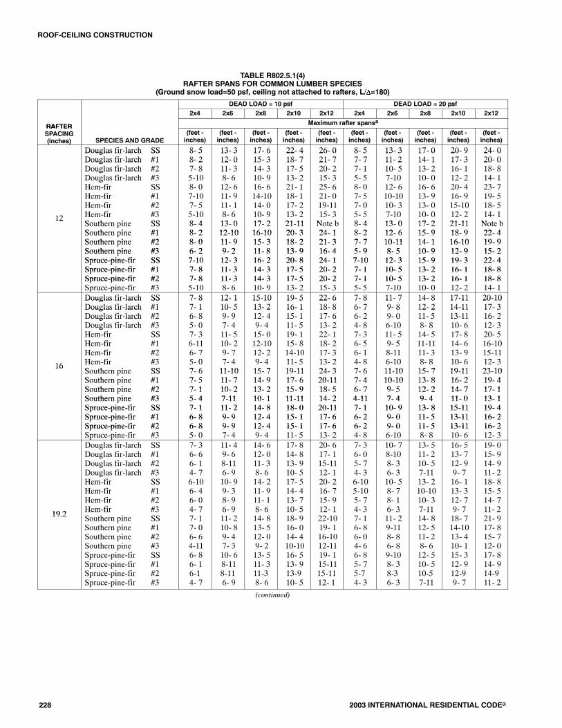
228 2003 INTERNATIONAL RESIDENTIAL CODE�
TABLE R802.5.1(4)RAFTER SPANS FOR COMMON LUMBER SPECIES
(Ground snow load=50 psf, ceiling not attached to rafters, L/�=180)
DEAD LOAD = 10 psf DEAD LOAD = 20 psf2x4 2x6 2x8 2x10 2x12 2x4 2x6 2x8 2x10 2x12
RAFTER Maximum rafter spansaRAFTERSPACING(inches) SPECIES AND GRADE
(feet -inches)
(feet -inches)
(feet -inches)
(feet -inches)
(feet -inches)
(feet -inches)
(feet -inches)
(feet -inches)
(feet -inches)
(feet -inches)
Douglas fir-larch SS 8- 5 13- 3 17- 6 22- 4 26- 0 8- 5 13- 3 17- 0 20- 9 24- 0Douglas fir larch SSDouglas fir-larch #1
8 58- 2
13 312- 0
17 615- 3
22 418- 7
26 021- 7
8 57- 7
13 311- 2
17 014- 1
20 917- 3
24 020- 0Douglas fir larch #1
Douglas fir-larch #28 27- 8
12 011- 3
15 314- 3
18 717- 5
21 720- 2
7 77- 1
11 210- 5
14 113- 2
17 316- 1
20 018- 8Douglas fir larch #2
Douglas fir-larch #37 85-10
11 38- 6
14 310- 9
17 513- 2
20 215- 3
7 15- 5
10 57-10
13 210- 0
16 112- 2
18 814- 1g
Hem-fir SSH fi #1
8- 07 10
12- 611 9
16- 614 10
21- 118 1
25- 621 0
8- 07 5
12- 610 10
16- 613 9
20- 416 9
23- 719 5Hem-fir #1
H fi #27-107 5
11- 911 1
14-1014 0
18- 117 2
21- 019 11
7- 57 0
10-1010 3
13- 913 0
16- 915 10
19- 518 5Hem-fir #2
H fi #37- 55 10
11- 18 6
14- 010 9
17- 213 2
19-1115 3
7- 05 5
10- 37 10
13- 010 0
15-1012 2
18- 514 112 Hem-fir #3
So thern pine SS5-108 4
8- 613 0
10- 917 2
13- 221 11
15- 3Note b
5- 58 4
7-1013 0
10- 017 2
12- 221 11
14- 1Note b
12Southern pine SSSouthern pine #1
8- 48 2
13- 012 10
17- 216 10
21-1120 3
Note b24 1
8- 48 2
13- 012 6
17- 215 9
21-1118 9
Note b22 4Southern pine #1
Southern pine #28- 28 0
12-1011 9
16-1015 3
20- 318 2
24- 121 3
8- 27 7
12- 610 11
15- 914 1
18- 916 10
22- 419 9Southern pine #2
Southern pine #38- 06- 2
11- 99- 2
15- 311- 8
18- 213- 9
21- 316- 4
7- 75- 9
10-118- 5
14- 110- 9
16-1012- 9
19- 915- 2Southern pine #3
Spruce-pine-fir SS6- 27-10
9- 212- 3
11- 816- 2
13- 920- 8
16- 424- 1
5- 97-10
8- 512- 3
10- 915- 9
12- 919- 3
15- 222- 4Spruce-pine-fir SS
Spruce-pine-fir #17-107- 8
12- 311- 3
16- 214- 3
20- 817- 5
24- 120- 2
7-107- 1
12- 310- 5
15- 913- 2
19- 316- 1
22- 418- 8Spruce-pine-fir #1
Spruce-pine-fir #27- 87- 8
11- 311- 3
14- 314- 3
17- 517- 5
20- 220- 2
7- 17- 1
10- 510- 5
13- 213- 2
16- 116- 1
18- 818- 8Spruce-pine-fir #2
Spruce-pine-fir #37- 85-10
11- 38- 6
14- 310- 9
17- 513- 2
20- 215- 3
7- 15- 5
10- 57-10
13- 210- 0
16- 112- 2
18- 814- 1
Douglas fir-larch SS 7- 8 12- 1 15-10 19- 5 22- 6 7- 8 11- 7 14- 8 17-11 20-10Douglas fir larch SSDouglas fir-larch #1
7 87- 1
12 110- 5
15 1013- 2
19 516- 1
22 618- 8
7 86- 7
11 79- 8
14 812- 2
17 1114-11
20 1017- 3Douglas fir larch #1
Douglas fir-larch #27 16- 8
10 59- 9
13 212- 4
16 115- 1
18 817- 6
6 76- 2
9 89- 0
12 211- 5
14 1113-11
17 316- 2Douglas fir larch #2
Douglas fir-larch #36 85- 0
9 97- 4
12 49- 4
15 111- 5
17 613- 2
6 24- 8
9 06-10
11 58- 8
13 1110- 6
16 212- 3g
Hem-fir SSH fi #1
7- 36 11
11- 510 2
15- 012 10
19- 115 8
22- 118 2
7- 36 5
11- 59 5
14- 511 11
17- 814 6
20- 516 10Hem-fir #1
H fi #26-116 7
10- 29 7
12-1012 2
15- 814 10
18- 217 3
6- 56 1
9- 58 11
11-1111 3
14- 613 9
16-1015 11Hem-fir #2
H fi #36- 75 0
9- 77 4
12- 29 4
14-1011 5
17- 313 2
6- 14 8
8-116 10
11- 38 8
13- 910 6
15-1112 316 Hem-fir #3
So thern pine SS5- 07 6
7- 411 10
9- 415 7
11- 519 11
13- 224 3
4- 87 6
6-1011 10
8- 815 7
10- 619 11
12- 323 10
16Southern pine SSSouthern pine #1
7- 67 5
11-1011 7
15- 714 9
19-1117 6
24- 320 11
7- 67 4
11-1010 10
15- 713 8
19-1116 2
23-1019 4Southern pine #1
Southern pine #27- 57 1
11- 710 2
14- 913 2
17- 615 9
20-1118 5
7- 46 7
10-109 5
13- 812 2
16- 214 7
19- 417 1Southern pine #2
Southern pine #37- 15- 4
10- 27-11
13- 210- 1
15- 911-11
18- 514- 2
6- 74-11
9- 57- 4
12- 29- 4
14- 711- 0
17- 113- 1Southern pine #3
Spruce-pine-fir SS5- 47- 1
7-1111- 2
10- 114- 8
11-1118- 0
14- 220-11
4-117- 1
7- 410- 9
9- 413- 8
11- 015-11
13- 119- 4Spruce-pine-fir SS
Spruce-pine-fir #17- 16- 8
11- 29- 9
14- 812- 4
18- 015- 1
20-1117- 6
7- 16- 2
10- 99- 0
13- 811- 5
15-1113-11
19- 416- 2Spruce-pine-fir #1
Spruce-pine-fir #26- 86- 8
9- 99- 9
12- 412- 4
15- 115- 1
17- 617- 6
6- 26- 2
9- 09- 0
11- 511- 5
13-1113-11
16- 216- 2Spruce-pine-fir #2
Spruce-pine-fir #36- 85- 0
9- 97- 4
12- 49- 4
15- 111- 5
17- 613- 2
6- 24- 8
9- 06-10
11- 58- 8
13-1110- 6
16- 212- 3
19 2
Douglas fir-larch SSDouglas fir-larch #1Douglas fir-larch #2Douglas fir-larch #3Hem-fir SSHem-fir #1Hem-fir #2Hem-fir #3
7- 36- 66- 14- 76-106- 46- 04- 7
11- 49- 68-116- 910- 99- 38- 96- 9
14- 612- 011- 38- 614- 211- 911- 18- 6
17- 814- 813- 910- 517- 514- 413- 710- 5
20- 617- 115-1112- 120- 216- 715- 912- 1
7- 36- 05- 74- 36-105-105- 74- 3
10- 78-108- 36- 310- 58- 78- 16- 3
13- 511- 210- 57-1113- 210-1010- 37-11
16- 513- 712- 99- 716- 113- 312- 79- 7
19- 015- 914- 911- 218- 815- 514- 711- 2
19.2Hem fir #3Southern pine SSSouthern pine #1Southern pine #2Southern pine #3Spruce-pine-fir SSSpruce-pine-fir #1Spruce-pine-fir #2Spruce-pine-fir #3
4 77- 17- 06- 64-116- 86- 16-14- 7
6 911- 210- 89- 47- 310- 68-118-116- 9
8 614- 813- 512- 09- 213- 511- 311-38- 6
10 518- 916- 014- 410-1016- 513- 913-910- 5
12 122-1019- 116-1012-1119- 115-1115-1112- 1
4 37- 16- 86- 04- 66- 85- 75-74- 3
6 311- 29-118- 86- 89-108- 38-36- 3
7 1114- 812- 511- 28- 612- 510- 510-57-11
9 718- 714-1013- 410- 115- 312- 912-99- 7
11 221- 917- 815- 712- 017- 814- 914-911- 2
(continued)

ROOF-CEILING CONSTRUCTION
2003 INTERNATIONAL RESIDENTIAL CODE� 229
TABLE R802.5.1(4)�continuedRAFTER SPANS FOR COMMON LUMBER SPECIES
(Ground snow load=50 psf, ceiling not attached to rafters, L/�=180)
DEAD LOAD = 10 psf DEAD LOAD = 20 psf
2x4 2x6 2x8 2x10 2x12 2x4 2x6 2x8 2x10 2x12
RAFTERMaximum rafter spansa
RAFTERSPACING(inches) SPECIES AND GRADE
(feet -inches)
(feet -inches)
(feet -inches)
(feet -inches)
(feet -inches)
(feet -inches)
(feet -inches)
(feet -inches)
(feet -inches)
(feet -inches)
Douglas fir-larch SS 6- 8 10- 3 13- 0 15-10 18- 4 6- 6 9- 6 12- 0 14- 8 17- 0gDouglas fir-larch #1Douglas fir larch #2
5-105 5
8- 67 11
10- 910 1
13- 212 4
15- 314 3
5- 55 0
7-107 4
10- 09 4
12- 211 5
14- 113 2Douglas fir-larch #2
Douglas fir-larch #35- 54- 1
7-116- 0
10- 17- 7
12- 49- 4
14- 310- 9
5- 03-10
7- 45- 7
9- 47- 1
11- 58- 7
13- 210- 0Douglas fir-larch #3
Hem-fir SSH fi #1
4- 16- 45 8
6- 09-118 3
7- 712- 910 6
9- 415- 712 10
10- 918- 014 10
3-106- 45 3
5- 79- 47 8
7- 111- 99 9
8- 714- 511 10
10- 016- 813 9Hem-fir #1
Hem fir #25- 85 4
8- 37 10
10- 69 11
12-1012 1
14-1014 1
5- 34 11
7- 87 3
9- 99 2
11-1011 3
13- 913 0
24
Hem-fir #2Hem-fir #3
5- 44- 1
7-106- 0
9-117- 7
12- 19- 4
14- 110- 9
4-113-10
7- 35- 7
9- 27- 1
11- 38- 7
13- 010- 024 Hem-fir #3
Southern pine SSS h i #1
4- 16- 76 5
6- 010- 49 7
7- 713- 812 0
9- 417- 514 4
10- 921- 017 1
3-106- 76 0
5- 710- 48 10
7- 113- 811 2
8- 716- 713 3
10- 019- 515 9
pSouthern pine #1Southern pine #2
6- 55-10
9- 78- 4
12- 010- 9
14- 412-10
17- 115- 1
6- 05- 5
8-107- 9
11- 210- 0
13- 311-11
15- 913-11Southern pine #2
Southern pine #35-104- 4
8- 46- 5
10- 98- 3
12-109- 9
15- 111- 7
5- 54- 1
7- 96- 0
10- 07- 7
11-119- 0
13-1110- 8Southern pine #3
Spruce-pine-fir SSS i fi #1
4 46- 25 5
6 59- 67 11
8 312- 010 1
9 914- 812 4
11 717- 114 3
4 16- 05 0
6 08-107 4
7 711- 29 4
9 013- 711 5
10 815- 913 2
p pSpruce-pine-fir #1Spruce-pine-fir #2
5- 55- 5
7-117-11
10- 110- 1
12- 412- 4
14- 314- 3
5- 05- 0
7- 47- 4
9- 49- 4
11- 511- 5
13- 213- 2Spruce-pine-fir #2
Spruce-pine-fir #35- 54- 1
7-116- 0
10- 17- 7
12- 49- 4
14- 310- 9
5- 03-10
7- 45- 7
9- 47- 1
11- 58- 7
13- 210- 0
Check sources for availability of lumber in lengths greater than 20 feet.
For SI: 1 inch = 25.4 mm, 1 foot = 304.8 mm, 1 pound per square foot = 0.0479 kN/m2.a. The tabulated rafter spansassume that ceiling joists are located at thebottomof theattic spaceor that someothermethodof resisting theoutwardpushof the rafterson the bearing walls, such as rafter ties, is provided at that location.When ceiling joists or rafter ties are located higher in the attic space, the rafter spans shall bemultiplied by the factors given below:
HC/HR Rafter Span Adjustment Factor
2/3 or greater 0.50
1/2 0.58
1/3 0.67
1/4 0.76
1/5 0.83
1/6 0.90
1/7.5 and less 1.00
where: HC = Height of ceiling joists or rafter ties measured vertically above the top of the rafter support walls.
HR = Height of roof ridge measured vertically above the top of the rafter support walls.
b. Span exceeds 26 feet in length.

ROOF-CEILING CONSTRUCTION
230 2003 INTERNATIONAL RESIDENTIAL CODE�
TABLE R802.5.1(5)RAFTER SPANS FOR COMMON LUMBER SPECIES
(Ground snow load=30 psf, ceiling attached to rafters, L/�=240)
DEAD LOAD = 10 psf DEAD LOAD = 20 psf
2x4 2x6 2x8 2x10 2x12 2x4 2x6 2x8 2x10 2x12
RAFTER Maximum rafter spansaRAFTERSPACING(inches) SPECIES AND GRADE
(feet -inches)
(feet -inches)
(feet -inches)
(feet -inches)
(feet -inches)
(feet -inches)
(feet -inches)
(feet -inches)
(feet -inches)
(feet -inches)
Douglas fir-larch SS 9- 1 14- 4 18-10 24- 1 Note b 9- 1 14- 4 18-10 24- 1 Note bDouglas fir larch SSDouglas fir-larch #1
9 18- 9
14 413- 9
18 1018- 2
24 122- 9
Note bNote b
9 18- 9
14 413- 2
18 1016- 8
24 120- 4
Note b23- 7Douglas fir larch #1
Douglas fir-larch #28 98- 7
13 913- 6
18 217- 5
22 921- 4
Note b24- 8
8 98- 5
13 212- 4
16 815- 7
20 419- 1
23 722- 1Douglas fir larch #2
Douglas fir-larch #38 77- 1
13 610- 5
17 513- 2
21 416- 1
24 818- 8
8 56- 4
12 49- 4
15 711- 9
19 114- 5
22 116- 8g
Hem-fir SSH fi #1
8- 78 5
13- 613 3
17-1017 5
22- 922 2
Note b25 9
8- 78 5
13- 612 10
17-1016 3
22- 919 10
Note b23 0Hem-fir #1
H fi #28- 58 0
13- 312 7
17- 516 7
22- 221 0
25- 924 4
8- 58 0
12-1012 2
16- 315 4
19-1018 9
23- 021 9Hem-fir #2
H fi #38- 07 1
12- 710 5
16- 713 2
21- 016 1
24- 418 8
8- 06 4
12- 29 4
15- 411 9
18- 914 5
21- 916 812 Hem-fir #3
So thern pine SS7- 18 11
10- 514 1
13- 218 6
16- 123 8
18- 8Note b
6- 48 11
9- 414 1
11- 918 6
14- 523 8
16- 8Note b
12Southern pine SSSouthern pine #1
8-118 9
14- 113 9
18- 618 2
23- 823 2
Note bNote b
8-118 9
14- 113 9
18- 618 2
23- 822 2
Note bNote bSouthern pine #1
Southern pine #28- 98 7
13- 913 6
18- 217 10
23- 222 3
Note bNote b
8- 98 7
13- 912 11
18- 216 8
22- 219 11
Note b23 4Southern pine #2
Southern pine #38- 77- 7
13- 611- 2
17-1014- 3
22- 316-10
Note b20- 0
8- 76- 9
12-1110- 0
16- 812- 9
19-1115- 1
23- 417-11Southern pine #3
Spruce-pine-fir SS7- 78- 5
11- 213- 3
14- 317- 5
16-1022- 3
20- 0Note b
6- 98- 5
10- 013- 3
12- 917- 5
15- 122- 3
17-11Note bSpruce-pine-fir SS
Spruce-pine-fir #18- 58- 3
13- 312-11
17- 517- 0
22- 321- 4
Note b24- 8
8- 58- 3
13- 312- 4
17- 515- 7
22- 319- 1
Note b22- 1Spruce-pine-fir #1
Spruce-pine-fir #28- 38- 3
12-1112-11
17- 017- 0
21- 421- 4
24- 824- 8
8- 38- 3
12- 412- 4
15- 715- 7
19- 119- 1
22- 122- 1Spruce-pine-fir #2
Spruce-pine-fir #38- 37- 1
12-1110- 5
17- 013- 2
21- 416- 1
24- 818- 8
8- 36- 4
12- 49- 4
15- 711- 9
19- 114- 5
22- 116- 8
Douglas fir-larch SS 8- 3 13- 0 17- 2 21-10 Note b 8- 3 13- 0 17- 2 21- 3 24- 8Douglas fir larch SSDouglas fir-larch #1
8 38- 0
13 012- 6
17 216- 2
21 1019- 9
Note b22-10
8 37-10
13 011- 5
17 214- 5
21 317- 8
24 820- 5Douglas fir larch #1
Douglas fir-larch #28 07-10
12 611-11
16 215- 1
19 918- 5
22 1021- 5
7 107- 3
11 510- 8
14 513- 6
17 816- 6
20 519- 2Douglas fir larch #2
Douglas fir-larch #37 106- 2
11 119- 0
15 111- 5
18 513-11
21 516- 2
7 35- 6
10 88- 1
13 610- 3
16 612- 6
19 214- 6g
Hem-fir SSH fi #1
7-107 8
12- 312 0
16- 215 9
20- 819 3
25- 122 3
7-107 7
12- 311 1
16- 214 1
20- 817 2
24- 219 11Hem-fir #1
H fi #27- 87 3
12- 011 5
15- 914 11
19- 318 2
22- 321 1
7- 77 2
11- 110 6
14- 113 4
17- 216 3
19-1118 10Hem-fir #2
H fi #37- 36 2
11- 59 0
14-1111 5
18- 213 11
21- 116 2
7- 25 6
10- 68 1
13- 410 3
16- 312 6
18-1014 616 Hem-fir #3
So thern pine SS6- 28 1
9- 012 9
11- 516 10
13-1121 6
16- 2Note b
5- 68 1
8- 112 9
10- 316 10
12- 621 6
14- 6Note b
16Southern pine SSSouthern pine #1
8- 18 0
12- 912 6
16-1016 6
21- 621 1
Note b25 7
8- 18 0
12- 912 6
16-1016 2
21- 619 2
Note b22 10Southern pine #1
Southern pine #28- 07 10
12- 612 3
16- 616 2
21- 119 3
25- 722 7
8- 07 10
12- 611 2
16- 214 5
19- 217 3
22-1020 2Southern pine #2
Southern pine #37-106- 7
12- 39- 8
16- 212- 4
19- 314- 7
22- 717- 4
7-105-10
11- 28- 8
14- 511- 0
17- 313- 0
20- 215- 6Southern pine #3
Spruce-pine-fir SS6- 77- 8
9- 812- 0
12- 415-10
14- 720- 2
17- 424- 7
5-107- 8
8- 812- 0
11- 015-10
13- 019- 9
15- 622-10Spruce-pine-fir SS
Spruce-pine-fir #17- 87- 6
12- 011- 9
15-1015- 1
20- 218- 5
24- 721- 5
7- 87- 3
12- 010- 8
15-1013- 6
19- 916- 6
22-1019- 2Spruce-pine-fir #1
Spruce-pine-fir #27- 67- 6
11- 911- 9
15- 115- 1
18- 518- 5
21- 521- 5
7- 37- 3
10- 810- 8
13- 613- 6
16- 616- 6
19- 219- 2Spruce-pine-fir #2
Spruce-pine-fir #37- 66- 2
11- 99- 0
15- 111- 5
18- 513-11
21- 516- 2
7- 35- 6
10- 88- 1
13- 610- 3
16- 612- 6
19- 214- 6
19 2
Douglas fir-larch SSDouglas fir-larch #1Douglas fir-larch #2Douglas fir-larch #3Hem-fir SSHem-fir #1Hem-fir #2Hem-fir #3
7- 97- 67- 45- 77- 47- 26-105- 7
12- 311- 810-118- 311- 711- 410- 98- 3
16- 114- 913- 910- 515- 314- 413- 710- 5
20- 718- 016-1012- 919- 517- 716- 712- 9
25- 020-1119- 614- 923- 720- 419- 314- 9
7- 97- 16- 85- 07- 46-116- 75- 0
12- 310- 59- 97- 411- 710- 29- 77- 4
15-1013- 212- 49- 415- 312-1012- 29- 4
19- 516- 115- 111- 519- 115- 814-1011- 5
22- 618- 817- 613- 222- 118- 217- 313- 2
19.2Hem fir #3Southern pine SSSouthern pine #1Southern pine #2Southern pine #3Spruce-pine-fir SSSpruce-pine-fir #1Spruce-pine-fir #2Spruce-pine-fir #3
5 77- 87- 67- 46- 07- 27- 07- 05- 7
8 312- 011- 911- 58-1011- 410-1110-118- 3
10 515-1015- 614- 911- 314-1113- 913- 910- 5
12 920- 219- 717- 713- 419- 016-1016-1012- 9
14 924- 723- 420- 715-1023- 119- 619- 614- 9
5 07- 87- 67- 15- 47- 26- 86- 85- 0
7 412- 011- 910- 27-1111- 49- 99- 97- 4
9 415-1014- 913- 210- 114- 912- 412- 49- 4
11 520- 217- 615- 911-1118- 015- 115- 111- 5
13 224- 720-1118- 514- 220-1117- 617- 613- 2
(continued)

ROOF-CEILING CONSTRUCTION
2003 INTERNATIONAL RESIDENTIAL CODE� 231
TABLE R802.5.1(5)�continuedRAFTER SPANS FOR COMMON LUMBER SPECIES
(Ground snow load=30 psf, ceiling attached to rafters, L/�=240)
DEAD LOAD = 10 psf DEAD LOAD = 20 psf
2x4 2x6 2x8 2x10 2x12 2x4 2x6 2x8 2x10 2x12
RAFTERMaximum rafter spansa
RAFTERSPACING(inches) SPECIES AND GRADE
(feet -inches)
(feet -inches)
(feet -inches)
(feet -inches)
(feet -inches)
(feet -inches)
(feet -inches)
(feet -inches)
(feet -inches)
(feet -inches)
Douglas fir-larch SSDouglas fir-larch #1
7- 37- 0
11- 410- 5
15- 013- 2
19- 116- 1
22- 618- 8
7- 36- 4
11- 39- 4
14- 211- 9
17- 414- 5
20- 116- 8Douglas fir larch #1
Douglas fir-larch #2Douglas fir-larch #3Hem fir SS
7 06- 85- 06 10
10 59- 97- 410 9
13 212- 49- 414 2
16 115- 111- 518 0
18 817- 613- 221 11
6 45-114- 66 10
9 48- 86- 710 9
11 911- 08- 413 11
14 513- 610- 217 0
16 815- 711-1019 9Hem-fir SS
Hem-fir #1Hem-fir #2
6-106- 86- 4
10- 910- 29- 7
14- 212-1012- 2
18- 015- 814-10
21-1118- 217- 3
6-106- 25-10
10- 99- 18- 7
13-1111- 610-10
17- 014- 013- 3
19- 916- 315- 5
24
Hem-fir #2Hem-fir #3Southern pine SS
6- 45- 07- 1
9- 77- 411- 2
12- 29- 414- 8
14-1011- 518- 9
17- 313- 222-10
5-104- 67- 1
8- 76- 711- 2
10-108- 414- 8
13- 310- 218- 9
15- 511-1022-10Southern pine SS
Southern pine #1Southern pine #2S th i #3
7 17- 06-105 4
11 210-1110- 27 11
14 814- 513- 210 1
18 917- 615- 911 11
22 1020-1118- 514 2
7 17- 06- 44 9
11 210- 69- 27 1
14 813- 211- 99 0
18 915- 814- 110 8
22 1018- 816- 612 8Southern pine #3
Spruce-pine-fir SSSpruce-pine-fir #1
5- 46- 86- 6
7-1110- 69- 9
10- 113-1012- 4
11-1117- 815- 1
14- 220-1117- 6
4- 96- 85-11
7- 110- 58- 8
9- 013- 211- 0
10- 816- 113- 6
12- 818- 815- 7Spruce-pine-fir #1
Spruce-pine-fir #2Spruce-pine-fir #3
6- 66- 65- 0
9- 99- 97- 4
12- 412- 49- 4
15- 115- 111- 5
17- 617- 613- 2
5-115-114- 6
8- 88- 86- 7
11- 011- 08- 4
13- 613- 610- 2
15- 715- 711-10
Check sources for availability of lumber in lengths greater than 20 feet.
For SI: 1 inch = 25.4 mm, 1 foot = 304.8 mm, 1 pound per square foot = 0.0479 kN/m2.a. The tabulated rafter spansassume that ceiling joists are located at thebottomof theattic spaceor that someothermethodof resisting theoutwardpushof the rafterson the bearing walls, such as rafter ties, is provided at that location.When ceiling joists or rafter ties are located higher in the attic space, the rafter spans shall bemultiplied by the factors given below:
HC/HR Rafter Span Adjustment Factor
2/3 or greater 0.50
1/2 0.58
1/3 0.67
1/4 0.76
1/5 0.83
1/6 0.90
1/7.5 and less 1.00
where: HC = Height of ceiling joists or rafter ties measured vertically above the top of the rafter support walls.
HR = Height of roof ridge measured vertically above the top of the rafter support walls.
b. Span exceeds 26 feet in length.

ROOF-CEILING CONSTRUCTION
232 2003 INTERNATIONAL RESIDENTIAL CODE�
TABLE R802.5.1(6)RAFTER SPANS FOR COMMON LUMBER SPECIES
(Ground snow load=50 psf, ceiling attached to rafters, L/�=240)
DEAD LOAD = 10 psf DEAD LOAD = 20 psf
2x4 2x6 2x8 2x10 2x12 2x4 2x6 2x8 2x10 2x12
RAFTER Maximum rafter spansaRAFTERSPACING(inches) SPECIES AND GRADE
(feet -inches)
(feet -inches)
(feet -inches)
(feet -inches)
(feet -inches)
(feet -inches)
(feet -inches)
(feet -inches)
(feet -inches)
(feet -inches)
Douglas fir-larch SS 7- 8 12- 1 15-11 20- 3 24- 8 7- 8 12- 1 15-11 20- 3 24- 0Douglas fir larch SSDouglas fir-larch #1
7 87- 5
12 111- 7
15 1115- 3
20 318- 7
24 821- 7
7 87- 5
12 111- 2
15 1114- 1
20 317- 3
24 020- 0Douglas fir larch #1
Douglas fir-larch #27 57- 3
11 711- 3
15 314- 3
18 717- 5
21 720- 2
7 57- 1
11 210- 5
14 113- 2
17 316- 1
20 018- 8Douglas fir larch #2
Douglas fir-larch #37 35-10
11 38- 6
14 310- 9
17 513- 2
20 215- 3
7 15- 5
10 57-10
13 210- 0
16 112- 2
18 814- 1g
Hem-fir SSH fi #1
7- 37 1
11- 511 2
15- 014 8
19- 218 1
23- 421 0
7- 37 1
11- 510 10
15- 013 9
19- 216 9
23- 419 5Hem-fir #1
H fi #27- 16 9
11- 210 8
14- 814 0
18- 117 2
21- 019 11
7- 16 9
10-1010 3
13- 913 0
16- 915 10
19- 518 5Hem-fir #2
H fi #36- 95 10
10- 88 6
14- 010 9
17- 213 2
19-1115 3
6- 95 5
10- 37 10
13- 010 0
15-1012 2
18- 514 112 Hem-fir #3
So thern pine SS5-107 6
8- 611 10
10- 915 7
13- 219 11
15- 324 3
5- 57 6
7-1011 10
10- 015 7
12- 219 11
14- 124 3
12Southern pine SSSouthern pine #1
7- 67 5
11-1011 7
15- 715 4
19-1119 7
24- 323 9
7- 67 5
11-1011 7
15- 715 4
19-1118 9
24- 322 4Southern pine #1
Southern pine #27- 57 3
11- 711 5
15- 415 0
19- 718 2
23- 921 3
7- 57 3
11- 710 11
15- 414 1
18- 916 10
22- 419 9Southern pine #2
Southern pine #37- 36- 2
11- 59- 2
15- 011- 8
18- 213- 9
21- 316- 4
7- 35- 9
10-118- 5
14- 110- 9
16-1012- 9
19- 915- 2Southern pine #3
Spruce-pine-fir SS6- 27- 1
9- 211- 2
11- 814- 8
13- 918- 9
16- 422-10
5- 97- 1
8- 511- 2
10- 914- 8
12- 918- 9
15- 222- 4Spruce-pine-fir SS
Spruce-pine-fir #17- 16-11
11- 210-11
14- 814- 3
18- 917- 5
22-1020- 2
7- 16-11
11- 210- 5
14- 813- 2
18- 916- 1
22- 418- 8Spruce-pine-fir #1
Spruce-pine-fir #26-116-11
10-1110-11
14- 314- 3
17- 517- 5
20- 220- 2
6-116-11
10- 510- 5
13- 213- 2
16- 116- 1
18- 818- 8Spruce-pine-fir #2
Spruce-pine-fir #36-115-10
10-118- 6
14- 310- 9
17- 513- 2
20- 215- 3
6-115- 5
10- 57-10
13- 210- 0
16- 112- 2
18- 814- 1
Douglas fir-larch SS 7- 0 11- 0 14- 5 18- 5 22- 5 7- 0 11- 0 14- 5 17-11 20-10Douglas fir larch SSDouglas fir-larch #1
7 06- 9
11 010- 5
14 513- 2
18 516- 1
22 518- 8
7 06- 7
11 09- 8
14 512- 2
17 1114-11
20 1017- 3Douglas fir larch #1
Douglas fir-larch #26 96- 7
10 59- 9
13 212- 4
16 115- 1
18 817- 6
6 76- 2
9 89- 0
12 211- 5
14 1113-11
17 316- 2Douglas fir larch #2
Douglas fir-larch #36 75- 0
9 97- 4
12 49- 4
15 111- 5
17 613- 2
6 24- 8
9 06-10
11 58- 8
13 1110- 6
16 212- 3g
Hem-fir SSH fi #1
6- 76 5
10- 410 2
13- 812 10
17- 515 8
21- 218 2
6- 76 5
10- 49 5
13- 811 11
17- 514 6
20- 516 10Hem-fir #1
H fi #26- 56 2
10- 29 7
12-1012 2
15- 814 10
18- 217 3
6- 56 1
9- 58 11
11-1111 3
14- 613 9
16-1015 11Hem-fir #2
H fi #36- 25 0
9- 77 4
12- 29 4
14-1011 5
17- 313 2
6- 14 8
8-116 10
11- 38 8
13- 910 6
15-1112 316 Hem-fir #3
So thern pine SS5- 06 10
7- 410 9
9- 414 2
11- 518 1
13- 222 0
4- 86 10
6-1010 9
8- 814 2
10- 618 1
12- 322 0
16Southern pine SSSouthern pine #1
6-106 9
10- 910 7
14- 213 11
18- 117 6
22- 020 11
6-106 9
10- 910 7
14- 213 8
18- 116 2
22- 019 4Southern pine #1
Southern pine #26- 96 7
10- 710 2
13-1113 2
17- 615 9
20-1118 5
6- 96 7
10- 79 5
13- 812 2
16- 214 7
19- 417 1Southern pine #2
Southern pine #36- 75- 4
10- 27-11
13- 210- 1
15- 911-11
18- 514- 2
6- 74-11
9- 57- 4
12- 29- 4
14- 711- 0
17- 113- 1Southern pine #3
Spruce-pine-fir SS5- 46- 5
7-1110- 2
10- 113- 4
11-1117- 0
14- 220- 9
4-116- 5
7- 410- 2
9- 413- 4
11- 016- 8
13- 119- 4Spruce-pine-fir SS
Spruce-pine-fir #16- 56- 4
10- 29- 9
13- 412- 4
17- 015- 1
20- 917- 6
6- 56- 2
10- 29- 0
13- 411- 5
16- 813-11
19- 416- 2Spruce-pine-fir #1
Spruce-pine-fir #26- 46- 4
9- 99- 9
12- 412- 4
15- 115- 1
17- 617- 6
6- 26- 2
9- 09- 0
11- 511- 5
13-1113-11
16- 216- 2Spruce-pine-fir #2
Spruce-pine-fir #36- 45- 0
9- 97- 4
12- 49- 4
15- 111- 5
17- 613- 2
6- 24- 8
9- 06-10
11- 58- 8
13-1110- 6
16- 212- 3
Douglas fir-larch SSD l fi l h #1
6- 76 4
10- 49 6
13- 712 0
17- 414 8
20- 617 1
6- 76 0
10- 48 10
13- 511 2
16- 513 7
19- 015 9
gDouglas fir-larch #1Douglas fir-larch #2
6- 46- 1
9- 68-11
12- 011- 3
14- 813- 9
17- 115-11
6- 05- 7
8-108- 3
11- 210- 5
13- 712- 9
15- 914- 9Douglas fir-larch #2
Douglas fir-larch #36- 14- 7
8-116- 9
11- 38- 6
13- 910- 5
15-1112- 1
5- 74- 3
8- 36- 3
10- 57-11
12- 99- 7
14- 911- 2Douglas fir larch #3
Hem-fir SSH fi #1
4 76- 26 1
6 99- 99 3
8 612-1011 9
10 516- 514 4
12 119-1116 7
4 36- 25 10
6 39- 98 7
7 1112-1010 10
9 716- 113 3
11 218- 815 5Hem-fir #1
Hem-fir #26- 15- 9
9- 38- 9
11- 911- 1
14- 413- 7
16- 715- 9
5-105- 7
8- 78- 1
10-1010- 3
13- 312- 7
15- 514- 7
19 2
Hem-fir #2Hem-fir #3
5- 94- 7
8- 96- 9
11- 18- 6
13- 710- 5
15- 912- 1
5- 74- 3
8- 16- 3
10- 37-11
12- 79- 7
14- 711- 2
19.2Hem fir #3Southern pine SSS th i #1
4 76- 56 4
6 910- 29 11
8 613- 413 1
10 517- 016 0
12 120- 919 1
4 36- 56 4
6 310- 29 11
7 1113- 412 5
9 717- 014 10
11 220- 917 8Southern pine #1
Southern pine #26- 46- 2
9-119- 4
13- 112- 0
16- 014- 4
19- 116-10
6- 46- 0
9-118- 8
12- 511- 2
14-1013- 4
17- 815- 7Southern pine #2
Southern pine #36- 24-11
9- 47- 3
12- 09- 2
14- 410-10
16-1012-11
6- 04- 6
8- 86- 8
11- 28- 6
13- 410- 1
15- 712- 0Southern pine #3
Spruce-pine-fir SSSpruce pine fir #1
4 116- 15 11
7 39- 68 11
9 212- 711 3
10 1016- 013 9
12 1119- 115 11
4 66- 15 7
6 89- 68 3
8 612- 510 5
10 115- 312 9
12 017- 814 9Spruce-pine-fir #1
Spruce-pine-fir #25-115-11
8-118-11
11- 311-3
13- 913- 9
15-1115-11
5-75-7
8-38-3
10- 510-5
12- 912-9
14- 914-9Spruce-pine-fir #2
Spruce-pine-fir #35-114- 7
8-116- 9
11-38- 6
13- 910- 5
15-1112- 1
5-74-3
8-36-3
10-57-11
12-99- 7
14-911- 2
(continued)
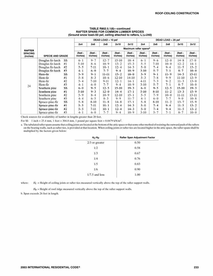
ROOF-CEILING CONSTRUCTION
2003 INTERNATIONAL RESIDENTIAL CODE� 233
TABLE R802.5.1(6)�continuedRAFTER SPANS FOR COMMON LUMBER SPECIES
(Ground snow load=50 psf, ceiling attached to rafters, L/�=240)
DEAD LOAD = 10 psf DEAD LOAD = 20 psf
2x4 2x6 2x8 2x10 2x12 2x4 2x6 2x8 2x10 2x12
RAFTERMaximum rafter spansa
RAFTERSPACING(inches) SPECIE AND GRADE
(feet -inches)
(feet -inches)
(feet -inches)
(feet -inches)
(feet -inches)
(feet -inches)
(feet -inches)
(feet -inches)
(feet -inches)
(feet -inches)
Douglas fir-larch SS 6- 1 9- 7 12- 7 15-10 18- 4 6- 1 9- 6 12- 0 14- 8 17- 0Douglas fir larch SSDouglas fir-larch #1D l fi l h #2
6 15-105 5
9 78- 67 11
12 710- 910 1
15 1013- 212 4
18 415- 314 3
6 15- 55 0
9 67-107 4
12 010- 09 4
14 812- 211 5
17 014- 113 2
gDouglas fir-larch #2Douglas fir-larch #3
5- 54- 1
7-116- 0
10- 17- 7
12- 49- 4
14- 310- 9
5- 03-10
7- 45- 7
9- 47- 1
11- 58- 7
13- 210- 0Douglas fir-larch #3
Hem-fir SS4- 15- 9
6- 09- 1
7- 711-11
9- 415- 2
10- 918- 0
3-105- 9
5- 79- 1
7- 111- 9
8- 714- 5
10- 015-11Hem-fir SS
Hem-fir #15- 95- 8
9- 18- 3
11-1110- 6
15- 212-10
18- 014-10
5- 95- 3
9- 17- 8
11- 99- 9
14- 511-10
15-1113- 9Hem fir #1
Hem-fir #2H fi #3
5 85- 44 1
8 37-106 0
10 69-117 7
12 1012- 19 4
14 1014- 110 9
5 34-113 10
7 87- 35 7
9 99- 27 1
11 1011- 38 7
13 913- 010 024 Hem-fir #3
Southern pine SS4- 16- 0
6- 09- 5
7- 712- 5
9- 415-10
10- 919- 3
3-106- 0
5- 79- 5
7- 112- 5
8- 715-10
10- 019- 3Southern pine SS
Southern pine #16- 05-10
9- 59- 3
12- 512- 0
15-1014- 4
19- 317- 1
6- 05-10
9- 58-10
12- 511- 2
15-1013- 3
19- 315- 9Southern pine #1
Southern pine #25-105- 9
9- 38- 4
12- 010- 9
14- 412-10
17- 115- 1
5-105- 5
8-107- 9
11- 210- 0
13- 311-11
15- 913-11Southern pine #2
Southern pine #3S i fi SS
5 94- 45 8
8 46- 58 10
10 98- 311 8
12 109- 914 8
15 111- 717 1
5 54- 15 8
7 96- 08 10
10 07- 711 2
11 119- 013 7
13 1110- 815 9Spruce-pine-fir SS
Spruce-pine-fir #15- 85- 5
8-107-11
11- 810- 1
14- 812- 4
17- 114- 3
5- 85- 0
8-107- 4
11- 29- 4
13- 711- 5
15- 913- 2Spruce-pine-fir #1
Spruce-pine-fir #25- 55- 5
7-117-11
10- 110- 1
12- 412- 4
14- 314- 3
5- 05- 0
7- 47- 4
9- 49- 4
11- 511- 5
13- 213- 2Spruce-pine-fir #2
Spruce-pine-fir #35- 54- 1
7-116- 0
10- 17- 7
12- 49- 4
14- 310- 9
5- 03-10
7- 45- 7
9- 47- 1
11- 58- 7
13- 210- 0
Check sources for availability of lumber in lengths greater than 20 feet.
For SI: 1 inch = 25.4 mm, 1 foot = 304.8 mm, 1 pound per square foot = 0.0479 kN/m2.a. The tabulated rafter spansassume that ceiling joists are located at thebottomof theattic spaceor that someothermethodof resisting theoutwardpushof the rafterson the bearing walls, such as rafter ties, is provided at that location.When ceiling joists or rafter ties are located higher in the attic space, the rafter spans shall bemultiplied by the factors given below:
HC/HR Rafter Span Adjustment Factor
2/3 or greater 0.50
1/2 0.58
1/3 0.67
1/4 0.76
1/5 0.83
1/6 0.90
1/7.5 and less 1.00
where: HC = Height of ceiling joists or rafter ties measured vertically above the top of the rafter support walls.
HR = Height of roof ridge measured vertically above the top of the rafter support walls.
b. Span exceeds 26 feet in length.

ROOF-CEILING CONSTRUCTION
234 2003 INTERNATIONAL RESIDENTIAL CODE�
TABLE R802.5.1(7)RAFTER SPANS FOR 70 PSF GROUND SNOW LOAD
(Ceiling not attached to rafters, L/�=180)
DEAD LOAD = 10 psf DEAD LOAD = 20 psf
2x4 2x6 2x8 2x10 2x12 2x4 2x6 2x8 2x10 2x12
RAFTERMaximum Rafter Spansa
RAFTERSPACING(inches) SPECIES AND GRADE
(feet -inches)
(feet -inches)
(feet -inches)
(feet -inches)
(feet -inches)
(feet -inches)
(feet -inches)
(feet -inches)
(feet -inches)
(feet -inches)
12
Douglas fir-larch SSDouglas fir-larch #1Douglas fir-larch #2Douglas fir-larch #3Hem-fir SSHem-fir #1Hem-fir #2Hem-fir #3Southern pine SSSouthern pine #1Southern pine #2Southern pine #3Spruce-pine-fir SSSpruce-pine-fir #1Spruce-pine-fir #2Spruce-pine-fir #3
7- 77- 16- 85- 07- 26-116- 75- 07- 57- 37- 15- 47- 06- 86- 85- 0
11-1010- 59- 97- 411- 310- 29- 77- 411- 811- 510- 27-1111- 09- 99- 97- 4
15- 813- 212- 49- 414- 912-1012- 29- 415- 414- 913- 210- 114- 612- 412- 49- 4
19- 516- 115- 111- 518-1015- 814-1011- 519- 717- 615- 911-1118- 015- 115- 111- 5
22- 618- 817- 613- 222- 118- 217- 313- 223-1020-1118- 514- 220-1117- 617- 613- 2
7- 76- 86- 34- 97- 26- 66- 24- 97- 57- 36- 85- 17- 06- 36- 34- 9
11-109-109- 26-1111- 39- 79- 16-1111- 811- 19- 77- 511- 09- 29- 26-11
15- 012- 511- 88- 914- 812- 111- 58- 915- 413-1112- 59- 613-1111- 811- 88- 9
18- 315- 214- 210- 918- 014-1014- 010- 919- 716- 614-1011- 317- 014- 214- 210- 9
21- 217- 716- 612- 520-1017- 216- 312- 523-1019- 817- 513- 419- 816- 616- 612- 5
16
Douglas fir-larch SSDouglas fir-larch #1Douglas fir-larch #2Douglas fir-larch #3Hem-fir SSHem-fir #1Hem-fir #2Hem-fir #3Southern pine SSSouthern pine #1Southern pine #2Southern pine #3Spruce-pine-fir SSSpruce-pine-fir #1Spruce-pine-fir #2Spruce-pine-fir #3
6-106- 25- 94- 46- 66- 05- 84- 46- 96- 76- 24- 86- 45- 95- 94- 4
10- 99- 08- 56- 410- 28- 98- 46- 410- 710- 28-106-1010- 08- 58- 56- 4
13- 911- 510- 88- 113- 511- 210- 68- 114- 012- 911- 58- 912- 910- 810- 88- 1
16-1013-1113- 19-1016- 613- 712-109-1017-1015- 213- 710- 415- 713- 113- 19-10
19- 616- 215- 211- 519- 215- 914-1111- 521- 818- 116- 012- 318- 115- 215- 211- 5
6-105-105- 54- 16- 65- 85- 44- 16- 96- 55-104- 46- 45- 55- 54- 1
10- 38- 67-116- 010- 18- 37-106- 010- 79- 78- 46- 59- 67-117-116- 0
13- 010- 910- 17- 712- 910- 69-117- 714- 012- 010- 98- 312- 010- 110- 17- 7
15-1013- 212- 49- 415- 712-1012- 19- 417-1014- 412-109- 914- 812- 412- 49- 4
18- 415- 314- 310- 918- 014-1014- 110- 921- 017- 115- 111- 717- 114- 314- 310- 9
19.2
Douglas fir-larch SSDouglas fir-larch #1Douglas fir-larch #2Douglas fir-larch #3Hem-fir SSHem-fir #1Hem-fir #2Hem-fir #3Southern pine SSSouthern pine #1Southern pine #2Southern pine #3Spruce-pine-fir SSSpruce-pine-fir #1Spruce-pine-fir #2Spruce-pine-fir #3
6- 55- 75- 34- 06- 15- 65- 24- 06- 46- 35- 74- 36- 05- 35- 34- 0
9-118- 37- 85-109- 78- 07- 75-1010- 09- 38- 16- 39- 27- 87- 85-10
12- 710- 59- 97- 412- 410- 29- 77- 413- 211- 810- 58- 011- 89- 99- 97- 4
15- 412- 911-119- 015- 112- 511- 99- 016- 913-1012- 59- 514- 311-1111-119- 0
17- 914- 913-1010- 517- 414- 513- 710- 520- 416- 614- 711- 216- 613-1013-1010- 5
6- 55- 45- 03- 96- 15- 24-113- 96- 45-115- 44- 05-115- 05- 03- 9
9- 47- 97- 35- 69- 27- 77- 25- 610- 08- 97- 75-118- 87- 37- 35- 6
11-109-109- 26-1111- 89- 79- 16-1113- 211- 09-107- 611- 09- 29- 26-11
14- 512- 011- 38- 614- 211- 811- 18- 616- 513- 111- 98-1013- 511- 311- 38- 6
16- 913-1113- 09-1015-513- 712-109-1019- 215- 713- 910- 715- 713- 013- 09-10
(continued)

ROOF-CEILING CONSTRUCTION
2003 INTERNATIONAL RESIDENTIAL CODE� 235
TABLE R802.5.1(7)�continuedRAFTER SPANS FOR 70 PSF GROUND SNOW LOAD
(Ceiling not attached to rafters, L/�=180)
DEAD LOAD = 10 psf DEAD LOAD = 20 psf
2x4 2x6 2x8 2x10 2x12 2x4 2x6 2x8 2x10 2x12
RAFTERMaximum rafter spansa
RAFTERSPACING(inches) SPECIES AND GRADE
(feet -inches)
(feet -inches)
(feet -inches)
(feet -inches)
(feet -inches)
(feet -inches)
(feet -inches)
(feet -inches)
(feet -inches)
(feet -inches)
24
Douglas fir-larch SSDouglas fir-larch #1Douglas fir-larch #2Douglas fir-larch #3Hem-fir SSHem-fir #1Hem-fir #2Hem-fir #3Southern pine SSSouthern pine #1Southern pine #2Southern pine #3Spruce-pine-fir SSSpruce-pine-fir #1Spruce-pine-fir #2Spruce-pine-fir #3
6- 05- 04- 83- 75- 84-114- 83- 75-115- 75- 03- 95- 64- 84- 83- 7
8-107- 46-115- 28- 87- 26- 95- 29- 38- 37- 35- 78- 36-116-115- 2
11- 39- 48- 96- 711- 09- 18- 76- 712- 210- 59- 47- 110- 58- 98- 96- 7
13- 911- 510- 88- 113- 611- 110- 68- 115- 712- 511- 18- 512- 910- 810- 88- 1
15-1113- 212- 49- 413-1112-1012- 29- 418- 214- 913- 010- 014- 912- 412- 49- 4
5- 94- 94- 53- 45- 74- 74- 43- 45-115- 34- 93- 75- 44- 54- 53- 4
8- 46-116- 64-118- 36- 96- 54-119- 37-106-105- 37- 96- 66- 64-11
10- 78- 98- 36- 310- 58- 78- 16- 312- 29-108- 96- 99-108- 38- 36- 3
12-1110- 910- 07- 712- 410- 69-117- 714- 811- 810- 67-1112- 010- 010- 07- 7
15- 012- 511- 88-1012-412- 211- 68-1017- 213-1112- 49- 512-1111- 811- 88-10
Check sources for availability of lumber in lengths greater than 20 feet.
For SI: 1 inch = 25.4 mm, 1 foot = 304.8 mm, 1 pound per square foot = 0.0479 kN/m2.a. The tabulated rafter spansassume that ceiling joists are located at thebottomof theattic spaceor that someothermethodof resisting theoutwardpushof the rafterson the bearing walls, such as rafter ties, is provided at that location.When ceiling joists or rafter ties are located higher in the attic space, the rafter spans shall bemultiplied by the factors given below:
HC/HR Rafter Span Adjustment Factor
2/3 or greater 0.50
1/2 0.58
1/3 0.67
1/4 0.76
1/5 0.83
1/6 0.90
1/7.5 and less 1.00
where: HC = Height of ceiling joists or rafter ties measured vertically above the top of the rafter support walls.
HR = Height of roof ridge measured vertically above the top of the rafter support walls.

ROOF-CEILING CONSTRUCTION
236 2003 INTERNATIONAL RESIDENTIAL CODE�
TABLE R802.5.1(8)RAFTER SPANS FOR 70 PSF GROUND SNOW LOAD
(Ceiling attached to rafters, L/�=240)
DEAD LOAD = 10 psf DEAD LOAD = 20 psf
2x4 2x6 2x8 2x10 2x12 2x4 2x6 2x8 2x10 2x12
RAFTERMaximum rafter spansa
RAFTERSPACING(inches) SPECIES AND GRADE
(feet -inches)
(feet -inches)
(feet -inches)
(feet -inches)
(feet -inches)
(feet -inches)
(feet -inches)
(feet -inches)
(feet -inches)
(feet -inches)
12
Douglas fir-larch SSDouglas fir-larch #1Douglas fir-larch #2Douglas fir-larch #3Hem-fir SSHem-fir #1Hem-fir #2Hem-fir #3Southern pine SSSouthern pine #1Southern pine #2Southern pine #3Spruce-pine-fir SSSpruce-pine-fir #1Spruce-pine-fir #2Spruce-pine-fir #3
6-106- 76- 65- 06- 66- 46- 15- 06- 96- 76- 65- 46- 46- 26- 25- 0
10- 910- 59- 97- 410- 210- 09- 67- 410- 710- 510- 27-1110- 09- 99- 97- 4
14- 313- 212- 49- 413- 512-1012- 29- 414- 013- 813- 210- 113- 212- 412- 49- 4
18- 216- 115- 111- 517- 215- 814-1011- 517-1017- 615- 911-1116- 915- 115- 111- 5
22- 118- 817- 613- 220-1018- 217- 313- 221- 820-1118- 514- 220- 517- 617- 613- 2
6-106- 76- 34- 96- 66- 46- 14- 96- 96- 76- 65- 16- 46- 26- 24- 9
10- 99-109- 26-1110- 29- 79- 16-1110- 710- 59- 77- 510- 09- 29- 26-11
14- 312- 511- 88- 913- 512- 111- 58- 914- 013- 812- 59- 613- 211- 811- 88- 9
18- 215- 214- 210- 917- 214-1014- 010- 917-1016- 614-1011- 316- 914- 214- 210- 9
21- 217- 716- 612- 520-1017- 216- 312- 521- 819- 817- 513- 419- 816- 616- 612- 5
16
Douglas fir-larch SSDouglas fir-larch #1Douglas fir-larch #2Douglas fir-larch #3Hem-fir SSHem-fir #1Hem-fir #2Hem-fir #3Southern pine SSSouthern pine #1Southern pine #2Southern pine #3Spruce-pine-fir SSSpruce-pine-fir #1Spruce-pine-fir #2Spruce-pine-fir #3
6- 36- 05- 94- 45-115- 95- 64- 46- 16- 05-114- 85- 95- 85- 84- 4
9-109- 08- 56- 49- 38- 98- 46- 49- 79- 58-106-109- 18- 58- 56- 4
12-1111- 510- 88- 112- 211- 210- 68- 112- 812- 511- 58- 911-1110- 810- 88- 1
16- 613-1113- 19-1015- 713- 712-109-1016- 215- 213- 710- 415- 313- 113- 19-10
19- 616- 215- 211- 518-1115- 914-1111- 519- 818- 116- 012- 318- 115- 215- 211- 5
6- 35-105- 54- 15-115- 85- 44- 16- 16- 05-104- 45- 95- 55- 54- 1
9-108- 67-116- 09- 38- 37-106- 09- 79- 58- 46- 59- 17-117-116- 0
12-1110- 910- 17- 712- 210- 69-117- 712- 812- 010- 98- 311-1110- 110- 17- 7
15-1013- 212- 49- 415- 712-1012- 19- 416- 214- 412-109- 914- 812- 412- 49- 4
18- 415- 314- 310- 918- 014-1014- 110- 919- 817- 115- 111- 717- 114- 314- 310- 9
19.2
Douglas fir-larch SSDouglas fir-larch #1Douglas fir-larch #2Douglas fir-larch #3Hem-fir SSHem-fir #1Hem-fir #2Hem-fir #3Southern pine SSSouthern pine #1Southern pine #2Southern pine #3Spruce-pine-fir SSSpruce-pine-fir #1Spruce-pine-fir #2Spruce-pine-fir #3
5-105- 75- 34- 05- 65- 55- 24- 05- 95- 85- 64- 35- 55- 35- 34- 0
9- 38- 37- 85-108- 88- 07- 75-109- 18-118- 16- 38- 67- 87- 85-10
12- 210- 59- 97- 411- 610- 29- 77- 411-1111- 810- 58- 011- 39- 99- 97- 4
15- 412- 911-119- 014- 812- 511- 99- 015- 313-1012- 59- 514- 311-1111-119- 0
17- 914- 913-1010- 517- 414- 513- 710- 518- 616- 614- 711- 216- 613-1013-1010- 5
5-105- 45- 03- 95- 65- 24-113- 95- 95- 85- 44- 05- 55- 05- 03- 9
9- 37- 97- 35- 68- 87- 77- 25- 69- 18- 97- 75-118- 67- 37- 35- 6
11-109-109- 26-1111- 69- 79- 16-1111-1111- 09-107- 611- 09- 29- 26-11
14- 512- 011- 38- 614- 211- 811- 18- 615- 313- 111- 98-1013- 511- 311- 38- 6
16- 913-1113- 09-1015-513- 712-109-1018- 615- 713- 910- 715- 713- 013- 09-10
(continued)

ROOF-CEILING CONSTRUCTION
2003 INTERNATIONAL RESIDENTIAL CODE� 237
TABLE R802.5.1(8)�continuedRAFTER SPANS FOR 70 PSF GROUND SNOW LOADa
(Ceiling attached to rafters, L/�=240)
DEAD LOAD = 10 psf DEAD LOAD = 20 psf
2x4 2x6 2x8 2x10 2x12 2x4 2x6 2x8 2x10 2x12
RAFTERMaximum rafter spansa
RAFTERSPACING(inches) SPECIES AND GRADE
(feet -inches)
(feet -inches)
(feet -inches)
(feet -inches)
(feet -inches)
(feet -inches)
(feet -inches)
(feet -inches)
(feet -inches)
(feet -inches)
24
Douglas fir-larch SSDouglas fir-larch #1Douglas fir-larch #2Douglas fir-larch #3Hem-fir SSHem-fir #1Hem-fir #2Hem-fir #3Southern pine SSSouthern pine #1Southern pine #2Southern pine #3Spruce-pine-fir SSSpruce-pine-fir #1Spruce-pine-fir #2Spruce-pine-fir #3
5- 55- 04- 83- 75- 24-114- 83- 75- 45- 35- 03- 95- 04- 84- 83- 7
8- 77- 46-115- 28- 17- 26- 95- 28- 58- 37- 35- 77-116-116-115- 2
11- 39- 48- 96- 710- 89- 18- 76- 711- 110- 59- 47- 110- 58- 98- 96- 7
13- 911- 510- 88- 113- 611- 110- 68- 114- 212- 511- 18- 512- 910- 810- 88- 1
15-1113- 212- 49- 413-1112-1012- 29- 417- 214- 913- 010- 014- 912- 412- 49- 4
5- 54- 94- 53- 45- 24- 74- 43- 45- 45- 34- 93- 75- 04- 54- 53- 4
8- 46-116- 64-118- 16- 96- 54-118- 57-106-105- 37- 96- 66- 64-11
10- 78- 98- 36- 310- 58- 78- 16- 311- 19-108- 96- 99-108- 38- 36- 3
12-1110- 910- 07- 712- 410- 69-117- 714- 211- 810- 67-1112- 010- 010- 07- 7
15- 012- 511- 88-1012-412- 211- 68-1017- 213-1112- 49- 512-1111- 811- 88-10
Check sources for availability of lumber in lengths greater than 20 feet.
For SI: 1 inch = 25.4 mm, 1 foot = 304.8 mm, 1 pound per square foot = 0.0479 kN/m2.a. The tabulated rafter spansassume that ceiling joists are located at thebottomof theattic spaceor that someothermethodof resisting theoutwardpushof the rafterson the bearing walls, such as rafter ties, is provided at that location.When ceiling joists or rafter ties are located higher in the attic space, the rafter spans shall bemultiplied by the factors given below:
HC/HR Rafter Span Adjustment Factor
2/3 or greater 0.50
1/2 0.58
1/3 0.67
1/4 0.76
1/5 0.83
1/6 0.90
1/7.5 and less 1.00
where: HC = Height of ceiling joists or rafter ties measured vertically above the top of the rafter support walls.
HR = Height of roof ridge measured vertically above the top of the rafter support walls.

ROOF-CEILING CONSTRUCTION
238 2003 INTERNATIONAL RESIDENTIAL CODE�
TABLE R802.5.1(9)RAFTER/CEILING JOIST HEEL JOINT CONNECTIONSa,b,c,d,e,f
GROUND SNOW LOAD (psf)
30 psf 50 psf 70 psf
Roof span (feet)
RAFTERRAFTERSPACING
12 20 28 36 12 20 28 36 12 20 28 36RAFTERSLOPE
SPACING(inches) Required number of 16d common nailsa,b per heel joint splicesc,d,e,f
3:12121624
457
6811
81116
111421
569
81116
121523
152030
6812
111421
152030
202639
4:12121624
345
569
6812
81116
457
6812
91217
111522
569
81116
121523
152029
5:12121624
334
457
5710
7913
346
5710
7914
91218
457
7913
91218
121623
7:12121624
333
345
457
569
334
457
5710
7913
345
569
7913
91117
9:12121624
333
334
346
457
333
346
458
5710
334
457
5710
7913
12:12121624
333
333
334
346
333
334
346
458
333
346
458
5710
For SI: 1 inch = 25.4 mm, 1 foot = 304.8 mm, 1 pound per square foot = 0.0479 kN/m2.a. 40d box nails shall be permitted to be substituted for 16d common nails.b. Nailing requirements shall be permitted to be reduced 25 percent if nails are clinched.c. Heel joint connections are not required when the ridge is supported by a load-bearing wall, header or ridge beam.d. When intermediate support of the rafter is provided by vertical struts or purlins to a loadbearing wall, the tabulated heel joint connection requirements shall bepermitted to be reduced proportionally to the reduction in span.
e. Equivalent nailing patterns are required for ceiling joist to ceiling joist lap splices.f. When rafter ties are substituted for ceiling joists, the heel joint connection requirement shall be taken as the tabulated heel joint connection requirement fortwo-thirds of the actual rafter-slope.

ROOF-CEILING CONSTRUCTION
2003 INTERNATIONAL RESIDENTIAL CODE� 239
RIDGE BOARD
PURLIN CONTINUOUSBETWEEN BRACES 2 IN. � 4 IN. BRACE
AT 4 FT. O.C.
NAIL TO JOIST
FOUNDATION
TOP PLATE CEILING JOIST�SEE TABLES R802.4(1)AND R802.4(2)
BEARINGPARTITIONS
45� MIN.
SUBFLOOR
BEARING WALL GIRDER
RAFTER SPAN�SEE TABLES R802.5.1(1)THROUGH R802.5.1(8)
FIGURE R802.5.1BRACED RAFTER CONSTRUCTION
Note:Where ceiling joints run perpendicular to the rafters, rafter ties shall be nailed to the rafter near the plate line and spaced not more than 4 feet on center.
��� ��� � �� � ��� ��� � ���� � ����� ��� � ������ � ����� ����
TABLE R802.11REQUIRED STRENGTH OF TRUSS OR RAFTER CONNECTIONS TO RESIST WIND UPLIFT FORCESa,b,c,e,f
(Pounds per connection)
BASIC WIND SPEED( d )
ROOF SPAN (feet) OVERHANGSd( d /f )
BASIC WIND SPEED(3-second gust) 12 20 24 28 32 36 40
OVERHANGS(pounds/feet)
85 -72 -120 -145 -169 -193 -217 -241 -38.55
90 -91 -151 -181 -212 -242 -272 -302 -43.22
100 -131 -218 -262 -305 -349 -393 -436 -53.36
110 -175 -292 -351 -409 -467 -526 -584 -64.56
For SI: 1 inch = 25.4 mm, 1 foot = 305 mm, 1 mph = 1.61 km/hr, 1 pound/foot = 14.5939 N/m, 1 pound = 0.454 kg.
a. The uplift connection requirements are based on a 30 foot mean roof height located in Exposure B. For Exposures C and D and for other mean roof heights,multiply the above loads by the Adjustment Coefficients in Table R-301.2(3).
b. The uplift connection requirements are based on the framing being spaced 24 inches on center. Multiply by 0.67 for framing spaced 16 inches on center andmultiply by 0.5 for framing spaced 12 inches on center.
c. The uplift connection requirements include an allowance for 10 pounds of dead load.
d. Theuplift connection requirementsdonot account for the effects ofoverhangs.Themagnitudeof the above loads shall be increasedby adding the overhang loadsfound in the table.Theoverhang loads are also basedon framing spaced24 incheson center.Theoverhang loadsgiven shall bemultiplied by theoverhangprojec-tion and added to the roof uplift value in the table.
e. The uplift connection requirements are based upon wind loading on end zones as defined in SectionM1609.6 of the International Building Code. Connectionloads for connections located a distance of 20% of the least horizontal dimension of the building from the corner of the building are permitted to be reduced bymultiplying the table connection value by 0.7 and multiplying the overhang load by 0.8.
f. Forwall-to-wall andwall-to-foundation connections, the capacity of the uplift connector is permitted to be reduced by 100 pounds for each fullwall above. (Forexample, if a 600-pound rated connector is used on the roof framing, a 500-pound rated connector is permitted at the next floor level down.)

ROOF-CEILING CONSTRUCTION
240 2003 INTERNATIONAL RESIDENTIAL CODE�
R802.10.5 Truss to wall connection. Trusses shall be con-nected to wall plates by the use of approved connectors hav-ing a resistance to uplift of not less than 175 pounds (79.45kg.) and shall be installed in accordance with the manufac-turer�s specifications. For roof assemblies subject to winduplift pressures of 20 pounds per square foot (0.958 kN/m2)or greater, as established in Table R301.2(2), adjusted forheight and exposure per Table R301.2(3), see sectionR802.11.
R802.11 Roof tie-down.
R802.11.1 Uplift resistance. Roof assemblies which aresubject to wind uplift pressures of 20 pounds per square foot(0.958 kN/m2) or greater shall have roof rafters or trusses at-tached to their supporting wall assemblies by connectionscapable of providing the resistance required in TableR802.11.Wind uplift pressures shall be determined using aneffectivewind area of 100 square feet (9.3m2) andZone 1 inTable R301.2(2), as adjusted for height and exposure perTable R301.2(3).
A continuous load path shall be provided to transmit theuplift forces from the rafter or truss ties to the foundation.
SECTION R803ROOF SHEATHING
R803.1 Lumber sheathing.Allowable spans for lumber usedas roof sheathing shall conform to Table R803.1. Spaced lum-ber sheathing for wood shingle and shake roofing shall con-form to the requirements of Sections R905.7 and R905.8.Spaced lumber sheathing is not allowed in Seismic DesignCategory D2.
TABLE R803.1MINIMUM THICKNESS OF LUMBER ROOF SHEATHING
RAFTER OR BEAM SPACING(inches)
MINIMUM NET THICKNESS(inches)
24 5/848a
60b 11/2 T & G72c
/2
For SI: 1 inch = 25.4 mm.a. Minimum 270 Fb, 340,000 E.b. Minimum 420 Fb, 660,000 E.c. Minimum 600 Fb, 1,150,000 E.
R803.2 Wood structural panel sheathing.
R803.2.1 Identification and grade.Wood structural panelsshall conform to DOC PS 1, DOC PS 2 or, when manufac-tured in Canada, CSA 0437, and shall be identified by grademark or certificate of inspection issued by an approvedagency.Wood structural panels shall complywith the gradesspecified in Table R503.2.1.1(1).
R803.2.1.1 Exposure durability. All wood structuralpanels, when designed to be permanently exposed in out-door applications, shall beof anexterior exposuredurabil-ity. Wood structural panel roof sheathing exposed to the
underside may be of interior type bonded with exteriorglue, identified as Exposure 1.
R803.2.1.2 Fire-retardant-treated plywood. The al-lowable unit stresses for fire-retardant-treated plywood,including fastener values, shall be developed from an ap-proved method of investigation that considers the effectsof anticipated temperature and humidity towhich the fire-retardant-treated plywood will be subjected, the type oftreatment and redrying process. The fire-retardant-treatedplywood shall be graded by an approved agency.
R803.2.2 Allowable spans. Themaximum allowable spansforwood structural panel roof sheathing shall not exceed thevalues set forth in Table R503.2.1.1(1).
R803.2.3 Installation. Wood structural panel used as roofsheathing shall be installed with joints staggered or non-staggered in accordance with Table R602.3(1), or APA E30for wood roof framing or with Table R804.3 for steel roofframing.
SECTION R804STEEL ROOF FRAMING
R804.1General. Elements shall be straight and free of any de-fects that would significantly affect their structural perfor-mance. Cold-formed steel roof framingmembers shall complywith the requirements of this section.
R804.1.1 Applicability limits. The provisions of this sec-tion shall control the construction of steel roof framing forbuildings not greater than 60 feet (18 288mm) in length per-pendicular to the joist, rafter or truss span, not greater than36feet (10 973 mm) in width parallel to the joist span or truss,not greater than two stories in height with each story notgreater than 10 feet (3048 mm) high, and roof slopes notsmaller than 3:12 (25-percent slope) or greater than 12:12(100-percent slope). Steel roof framingconstructed in accor-dance with the provisions of this section shall be limited tosites subjected to a maximum design wind speed of 110miles per hour (209 km/h) Exposure A, B or C and a maxi-mum ground snow load of 70 psf (3.35 kN/m2).
R804.1.2 In-line framing.Steel roof framing constructed inaccordance with Section R804 shall be located directly in-line with load-bearing studs below with a maximum toler-ance of 3/4 inch (19.1mm) between the centerline of the studand roof joist/rafter.
R804.1.3 Roof trusses. The design, quality assurance,installation and testing of cold-formed steel trusses shall bein accordancewith theAISI Standard for Cold-formed SteelFraming-Truss Design (COFS/Truss).
R804.2 Structural framing. Load-bearing steel roof framingmembers shall comply with Figure R804.2(1) and the dimen-sional and minimum thickness requirements specified inTables R804.2(1) and R804.2(2). Tracks shall comply withFigure R804.2(2) and shall have a minimum flange width of11/4 inches (32 mm). The maximum inside bend radius forload-bearingmembers shall be the greater of 3/32 inch (2.4mm)or twice the uncoated steel thickness. Holes in roof framing
�

ROOF-CEILING CONSTRUCTION
2003 INTERNATIONAL RESIDENTIAL CODE� 241
members shall not exceed 1.5 inches (38 mm) in width or 4inches (102mm) in length as shown inFigureR804.2(3).Holesshall be permitted only along the centerline of the web of theframing member. Holes shall not be less than 24 inches (610mm) center-to-center and shall not be located less than 10 inch-es (254mm) from the edge of the hole to the edge of the bearingsurface or support unless patched in accordance with SectionR804.3.6.
R804.2.1 Material. Load-bearing steel framing membersshall be cold-formed to shape from structural qualitysheet steel complying with the requirements of one of thefollowing:
1. ASTM A 653; Grades 33, 37, 40 and 50 (Classes1and 3).
2. ASTM A 792; Grades 33, 37, 40 and 50A.
3. ASTM A 875; Grades 33, 37, 40 and 50 (Classes 1and 3).
4. Steels that comply with ASTMA 653, except for ten-sile and elongation, shall be permitted provided theratio of tensile strength to yield point is at least 1.08and the total elongation is at least 10 percent for a2-inch (51mm) gage length or 7 percent for an 8-inch(203 mm) gage length.
R804.2.2 Identification. Load-bearing steel framing mem-bers shall have a legible label, stencil, stamp or embossmentwith the following information as a minimum:
1. Manufacturer�s identification.2. Minimum uncoated steel thickness in inches (mm).3. Minimum coating designation.4. Minimumyield strength, in kips per square inch (ksi).
TABLE R804.2(1)LOAD-BEARING COLD-FORMED STEEL MEMBER SIZES
NOMINAL MEMBER SIZEMEMBER DESIGNATIONa
WEB DEPTH(inches)
MINIMUM FLANGE WIDTH(inches)
MAXIMUM FLANGE WIDTH(inches)
MINIMUM LIP SIZE(inches)
350S162-t 3.5 1.625 2 0.5550S162-t 5.5 1.625 2 0.5800S162-t 8 1.625 2 0.51000S162-t 10 1.625 2 0.51200S162-t 12 1.625 2 0.5
For SI: 1 inch = 25.4 mm.a. Themember designation is defined by the first number representing themember depth in 1/100 inch, the letter �s� representing a stud or joistmember, the secondnumber representing the flange width in 1/100 inch, and the letter �t� shall be a number representing the minimum base metal thickness in mils [see TableR804.2(2)].
TABLE R804.2(2)MINIMUM THICKNESS OF COLD-FORMED STEEL ROOF FRAMING MEMBERS
DESIGNATION (mils) MINIMUM UNCOATED THICKNESS (inches) REFERENCED GAGE NUMBER
33 0.033 2043 0.043 1854 0.054 1668 0.068 14
For SI: 1 inch = 25.4 mm, 1 mil = 0.0254 mm.

ROOF-CEILING CONSTRUCTION
242 2003 INTERNATIONAL RESIDENTIAL CODE�
24 IN. MIN.
FIGURE R804.2(3)WEB HOLES
FLANGE
DEPTH OF WEB(OUTSIDE TO OUTSIDE)
SIZE OF TRACK(INSIDE TO INSIDE)LIP
WEB
FLANGE
WEB
10 IN. MIN.
4 IN. MAX.1.5 IN.MAX.
C
BEARING CONDITION
FIGURE R804.2(1)C-SECTION
FIGURE R804.2(2)TRACK SECTION
��� ��� � �� � ��� ���
C LL
R804.2.3 Corrosion protection. Load-bearing steel fram-ing shall have a metallic coating complying with one of thefollowing:
1. AminimumofG60 in accordancewithASTMA653.2. A minimum of AZ 50 in accordance with ASTM A
792.3. A minimum of GF 60 in accordance with ASTM A
875.
R804.2.4 Fastening requirements. Screws for steel-to-steel connections shall be installed with a minimum edgedistance and center-to-center spacing of 1/2 inch (12.7 mm),shall be self-drilling tapping, and shall conform to SAE J78.Structural sheathing shall be attached to roof rafters withminimumNo. 8 self-drilling tapping screws that conform toSAE J78. Screws for attaching structural sheathing to steelroof framing shall have a minimum head diameter of 0.292
inch (7.4 mm) with countersunk heads and shall be installedwith aminimumedge distance of 3/8 inch (9.5mm).Gypsumboard ceilings shall be attached to steel joists withminimumNo. 6 screws conforming to ASTM C 954 and shall beinstalled in accordance with Section R805. For all connec-tions, screws shall extend through the steel a minimum ofthree exposed threads. All self-drilling tapping screws con-forming to SAE J78 shall have aminimumType II coating inaccordance with ASTM B 633.
Where No. 8 screws are specified in a steel-to-steel con-nection, the required number of screws in the connection ispermitted to be reduced in accordance with the reductionfactors in Table R804.2.4 when larger screws are used orwhenoneof the sheetsof steel being connected is thicker that33 mils (0.84 mm). When applying the reduction factor, theresulting number of screws shall be rounded up.

ROOF-CEILING CONSTRUCTION
2003 INTERNATIONAL RESIDENTIAL CODE� 243
TABLE R804.2.4SCREW SUBSTITUTION FACTOR
THINNEST CONNECTED STEEL SHEET (mils)
SCREW SIZE 33 43
#8 1.0 0.67
#10 0.93 0.62
#12 0.86 0.56
For SI: 1 mil = 0.0254 mm.
R804.3 Roof construction. Steel roof systems constructed inaccordance with the provisions of this section shall consist ofboth ceiling joists and rafters in accordancewith FigureR804.3and fastened in accordance with Table R804.3.
R804.3.1 Allowable ceiling joist spans. The clear span ofcold-formed steel ceiling joists shall not exceed the limits setforth in Table R804.3.1(1) or R804.3.1(2). Ceiling joistsshall have a minimum bearing length of 1.5 inches (38 mm)and shall be connected to rafters (heel joint) in accordancewith Figure R804.3.1(1) and Table R804.3.1(3). When con-tinuous joists are framedacross interior bearing supports, theinterior bearing supports shall be located within 24 inches(610mm) of midspan of the ceiling joist , and the individualspans shall not exceed the applicable spans in TableR804.3.1(1) or R804.3.1(2). Where required in TableR804.3.1(1) or R804.3.1(2), bearing stiffeners shall beinstalled at each bearing location in accordancewith SectionR804.3.8 andFigureR804.3.8.When the attic is to beusedasan occupied space, the ceiling joists shall be designed in ac-cordance with Section R505.
R804.3.2 Ceiling joist bracing.The bottom flanges of steelceiling joists shall be laterally braced in accordance withSection R702. The top flanges of steel ceiling joists shall belaterally bracedwith aminimum of 33mil (0.84mm)C-sec-tion, 33 mil (0.84 mm) track section, or 11/2 inch by 33 mil(38 mm by 0.84 mm) continuous steel strapping as required
inTableR804.3.1(1) orR804.3.1(2).Lateralbracing shallbeinstalled in accordance with Figure R804.3. C-section,tracks or straps shall be fastened to the top flange at each joistwith at least one No. 8 screw and shall be fastened to block-ing with at least two No. 8 screws. Blocking or bridging (X-bracing) shall be installed between joists in-line with strapbracing at a maximum spacing of 12 feet (3658 mm) mea-sured perpendicular to the joists, and at the termination of allstraps. The third point bracing span values from TableR804.3.1(1) or R804.3.1(2) shall be used for straps installedat closer spacings than thirdpoint bracing,orwhensheathingis applied to the top of the ceiling joists.
R804.3.3 Allowable rafter spans. The horizontal projec-tion of the rafter span, as shown in Figure R804.3, shall notexceed the limits set forth inTableR804.3.3(1).Wind speedsshall be converted to equivalent ground snow loads in accor-dancewith Table R804.3.3(2). Rafter spans shall be selectedbasedon thehigher of theground snow loador theequivalentsnow load converted from thewind speed.When required, arafter support brace shall be a minimum of 350S162-33 C-section with maximum length of 8 feet (2438mm) and shallbe connected to a ceiling joist and rafter with four No. 10screws at each end.
R804.3.3.1Rafter framing.Rafters shall be connected toa parallel ceiling joist to forma continuous tie betweenex-terior walls in accordance with Figures R804.3 andR804.3.1(1) and Table R804.3.1(3). Rafters shall be con-nected to a ridge member with a minimum 2-inch by2-inch (51 mm by 51 mm) clip angle fastened with mini-mum No. 10 screws to the ridge member in accordancewith Figure R804.3.3.1 and Table R804.3.3.1. The clipangle shall have a minimum steel thickness as the raftermember and shall extend the full depth of the rafter mem-ber. The ridge member shall be fabricated from a C-sec-tion and a track section, which shall be of a minimum sizeand steel thickness as the adjacent rafters and shall beinstalled in accordance with Figure R804.3.3.1.
TABLE R804.3ROOF FRAMING FASTENING SCHEDULEa,b
DESCRIPTION OF BUILDING ELEMENTS NUMBER AND SIZE OF FASTENERS SPACING OF FASTENERS
Ceiling joist to top trackof load-bearing wall
2 No. 10 screws Each joist
Roof sheathing (oriented strand boardor plywood) to rafters
No. 8 screws6� o.c. on edges and 12� o.c. at interiorsupports. 6� o.c. at gable end truss
Truss to bearing walla 2 No. 10 screws Each trussGable end truss to endwall top track No. 10 screws 12� o.c.
Rafter to ceiling joist Minimum No. 10 screws,per Table R804.3.1(3)
Evenly spaced, less than 1/2� from all edges.
For SI: 1 inch = 25.4 mm, 1 foot = 304.8 mm, 1 pound per square foot = 0.0479 kN/m2, 1 mil = 0.0254 mm.
a. Screwsshall beapplied through the flangesof the trussorceiling joist ora54mil clipangle shall beusedwith twoNo.10screws in each leg. SeeSectionR804.4 foradditional requirements to resist uplift forces.
b. Spacingof fastenerson roof sheathingpanel edges applies to panel edges supportedby framingmembers andat all roofplaneperimeters.Blockingof roofsheath-ingpanel edgesperpendicular to the framingmembers shall not be required except at the intersectionofadjacent roofplanes.Roofperimeter shall be supportedbyframing members or cold-formed blocking of the same depth and gauge as the floor members.
�

ROOF-CEILING CONSTRUCTION
244 2003 INTERNATIONAL RESIDENTIAL CODE�
LOAD-BEARINGWALL
FIGURE R804.3STEEL ROOF CONSTRUCTION
RAFTER SPANWITH RAFTERSUPPORT BRACE
LOAD-BEARING WALLSHALL BE INSTALLED WHENRAFTER BRACE IS USED
CEILING JOIST SPAN
6 IN. MAX. TO CENTEROF SCREW PATTERN1/2 IN. GYPSUM
BOARD
45�MIN.
CEILING JOIST
350S162-33 MILC- OR TRACK SECTIONOR STRAP FORCEILING JOIST TOPFLANGE BRACING
CANTILEVER2 FT. MAX.
LOAD-BEARINGWALL
HEEL JOINTSEE FIGURER804.3.1(1)
WHEN INSTALLED, RAFTERSUPPORT BRACE SHALL BE AMINIMUM OF 350S162-33 MILC-SECTION, CONNECTED TO EACHCEILING JOIST AND RAFTER WITH4 SCREWS AT EACH END (COPEFLANGES OF BRACE AT CEILINGJOIST CONNECTION OR USEGUSSET PLATE)
RAFTER SPAN WITHOUT RAFTERSUPPORT BRACE
RAFTER BOTTOM FLANGE BRACING(FLAT STRAP, 350S162-33 MILC-SECTION, OR TRACK SECTION)
RAFTER
RIDGE MEMBER�SEE FIGURE R804.3.3.1
C-SECTION OR TRACK INSTALLEDAT 4 FT. O.C. TO RAFTER SUPPORTBRACE
RAFTER BOTTOM FLANGE BRACING(FLAT STRAP, 350S162-33 MILC-SECTION, OR TRACK SECTION)
��� ��� � �� � ��� ��� � ���� � ����� ��� � ��� � ��� �� ���
R804.3.3.2 Roof cantilevers. Roof cantilevers shall notexceed 24 inches (610 mm) in accordance with FigureR804.3.Roof cantilevers shall be supported by a header inaccordance with Section R603.6 or shall be supported bythe floor framing in accordance with Section R505.3.7.
R804.3.4 Rafter bottom flange bracing. The bottomflanges of steel rafters shall be continuously braced with aminimum 33-mil (0.84 mm) C-section, 33-mil (0.84 mm)track section, or a 11/2-inch by 33-mil (38 mm by 0.84 mm)steel strapping at amaximum spacing of 8 feet (2438mm) asmeasured parallel to the rafters. Bracing shall be installed inaccordance with Figure R804.3. The C-section, track sec-tion, or straps shall be fastened to blocking with at least twoNo. 8 screws. Blocking or bridging (X-bracing) shall beinstalled between rafters in-line with the continuous bracingat a maximum spacing of 12 feet (3658 mm) measured per-pendicular to the rafters and at the termination of all straps.
The ends of continuous bracing shall be fastened to blockingwith at least two No. 8 screws.
R804.3.5 Cutting and notching. Flanges and lips of load-bearing steel roof framing members shall not be cut ornotched. Holes in webs shall be in accordance with SectionR804.2.
R804.3.6 Hole patching. Holes in ceiling joist and rafterswith dimensionsconforming toSectionR804.2 that are clos-er than 10 inches (254 mm) from the edge of the hole to theedge of bearing surface shall be patched with a solid steelplate, C-section or track section in accordance with FigureR804.3.6. The steel patch shall be of aminimum thickness asthe receiving member and shall extend at least 1 inch (25.4mm) beyond all edges of the hole. The steel patch shall befastened to the webwith No. 8 screws (minimum) spaced nogreater than 1 inch (25.4 mm) center-to-center along theedges of the patch, with aminimumedge distance of 1/2 inch(12.7 mm).

ROOF-CEILING CONSTRUCTION
2003 INTERNATIONAL RESIDENTIAL CODE� 245
TABLE R804.3.1(1)ALLOWABLE SPANS FOR COLD-FORMED STEEL CEILING JOISTSa,b,c 10 psf live load (no attic storage)
LATERAL SUPPORT OF TOP (COMPRESSION) FLANGE
Unbraced Mid-span bracing Third-point bracing
NOMINAL JOIST Spacing (inches) Spacing (inches) Spacing (inches)NOMINAL JOISTSIZE 16 24 16 24 16 24
350S162-33 9�-2� 8�-3� 11�-9� 10�-1� 11�-9� 10�-4�350S162-43 9�-11� 8�-10� 12�-10� 11�-2� 12�-10� 11�-2�350S162-54 10�-8� 9�-6� 13�-9� 12�-0� 13�-9� 12�-0�350S162-68 11�-7� 10�-4� 14�-8� 12�-10� 14�-8� 12�-10�550S162-33 10�-5� 9�-5� 14�-5� 12�-8�c 16�-4� 13�-10�c
550S162-43 11�-2� 10�-1� 15�-7� 13�-10� 18�-0� 15�-5�550S162-54 12�-0� 10�-9� 16�-7� 14�-9� 19�-5� 16�-8�550S162-68 12�-11� 11�-7� 17�-8� 15�-10� 20�-11� 18�-1�800S162-33 11�-8�c 10�-6�c 16�-5�c 14�-9�c 19�-5�c 16�-7�c
800S162-43 12�-6� 11�-3� 17�-6� 15�-10� 21�-2� 18�-7�800S162-54 13�-4� 11�-11� 18�-7� 16�-9� 22�-7� 20�-0�800S162-68 14�-3� 12�-9� 19�-8� 17�-8� 23�-11� 21�-4�1000S162-43 13�-4�c 12�-1�c 18�-9�c 16�-11�c 22�-11�c 20�-6�c
1000S162-54 14�-2� 12�-9� 19�-10� 17�-10� 24�-2� 21�-9�1000S162-68 15�-2� 13�-7� 21�-0� 18�-11� 25�-6� 23�-0�1200S162-43 14�-1�c 12�-8�c 19�-10�c 17�-11�c 24�-3�c 21�-6�c
1200S162-54 15�-0�c 13�-5�c 20�-11�c 18�-11�c 25�-7�c 23�-1�c
1200S162-68 15�-11� 14�-4� 22�-2� 19�-11� 27�-0� 24�-4�For SI: 1 inch = 25.4 mm, 1 foot = 304.8 mm, 1 pound per square foot = 0.0479 kN/m2.a. Deflection criteria: L/240 for total loads.b. Ceiling dead load = 5 psf.c. Bearing stiffeners are required at all bearing points and concentrated load locations.
TABLE R804.3.1(2)ALLOWABLE SPANS FOR COLD-FORMED STEEL CEILING JOISTSa,b,c
20 psf live load (Limited attic storage where development of future rooms is not possible)
LATERAL SUPPORT OF TOP FLANGE
Unbraced Mid-span bracing Third-point bracing
NOMINAL JOIST Spacing (inches) Spacing (inches) Spacing (inches)NOMINAL JOISTSIZE 16 24 16 24 16 24
350S162-33 8�-0� 6�-0� 9�-8� 6�-0� 9�-0� 6�-0�350S162-43 8�-8� 7�-8� 10�-9� 9�-1� 10�-10� 9�-5�350S162-54 9�-3� 8�-3� 11�-7� 9�-11� 11�-7� 10�-1�350S162-68 10�-0� 8�-11� 12�-5� 10�-10� 12�-5� 10�-10�550S162-33 9�-2� 6�-0� 12�-2�c 10�-5�c 13�-3� 11�-0�c
550S162-43 9�-10� 8�-10� 13�-4� 11�-6� 14�-9� 12�-5�550S162-54 10�-5� 9�-5� 14�-4� 12�-6� 16�-1� 13�-7�550S162-68 11�-3� 10�-0� 15�-4� 13�-5� 17�-5� 14�-10�800S162-33 10�-3�c 9�-3�c 14�-4�c 12�-5�c 15�-11�c 13�-4�c
800S162-43 10�-11� 9�-10� 15�-5� 13�-8�c 17�-11�c 15�-5�c
800S162-54 11�-8� 10�-6� 16�-3� 14�-7� 19�-3� 16�-8�800S162-68 12�-5� 11�-2� 17�-3� 15�-6� 20�-7� 18�-0�1000S162-43 11�-9� 10�-7�c 16�-6�c 14�-10�c 19�-10�c 17�-1�c
1000S162-54 12�-5� 11�-2� 17�-5� 15�-8� 21�-1� 18�-7�1000S162-68 13�-3� 11�-10� 18�-5� 16�-7� 22�-4� 19�-11�1200S162-43 12�-5�c 11�-2�c 17�-5�c 15�-8�c 20�-9�c 18�-0�c
1200S162-54 13�-1�c 11�-9�c 18�-5�c 16�-7�c 22�-5�c 20�-1�c
1200S162-68 13�-11� 12�-6� 19�-5� 17�-6� 23�-8� 21�-3�
For SI: 1 inch = 25.4 mm, 1 foot = 304.8 mm, 1 pound per square foot = 0.0479 kN/m2.a. Deflection criteria: L/240 for total loads.b. Ceiling dead load = 5 psf.c. Bearing stiffeners are required at all bearing points and concentrated load locations.

ROOF-CEILING CONSTRUCTION
246 2003 INTERNATIONAL RESIDENTIAL CODE�
TABLE R804.3.1(3)NUMBER OF SCREWS REQUIRED FOR CEILING JOIST TO RAFTER CONNECTIONa
BUILDING WIDTH (feet)
24 28 32 36
Ground snow load(psf)
Ground snow load(psf)
Ground snow load(psf)
Ground snow load(psf)
ROOF SLOPE 20 30 50 70 20 30 50 70 20 30 50 70 20 30 50 70
3/12 5 6 9 12 6 7 10 13 7 8 12 15 8 9 13 174/12 4 5 7 9 5 6 8 10 6 6 9 12 6 7 10 135/12 4 4 6 7 4 5 7 9 5 5 8 10 5 6 9 116/12 3 4 5 7 4 4 6 8 4 5 7 9 4 5 7 107/12 3 3 5 6 3 4 5 7 4 4 6 8 4 5 7 98/12 3 3 4 5 3 3 5 6 3 4 5 7 4 4 6 89/12 2 3 4 5 3 3 4 6 3 4 5 6 3 4 6 710/12 2 3 4 5 3 3 4 5 3 3 5 6 3 4 5 711/12 2 3 4 4 3 3 4 5 3 3 5 6 3 4 5 612/12 2 3 3 4 2 3 4 5 3 3 4 6 3 4 5 6
For SI: 1 foot = 304.8 mm, 1 pound per square foot = 0.0479 kN/m2.a. Screws shall be No. 10 minimum.
ROOF TO WALL CONNECTIONWITH TWO SCREWS THROUGHCEILING JOIST FLANGE, 54 MIL(MIN.) ANGLE
FIGURE R804.3.1(1)JOIST TO RAFTER CONNECTION
TRACK
RAFTER
CEILING JOIST
LOAD-BEARING STUD
HEEL JOINT CONNECTION WITHSCREWS (AS REQUIRED)
��� ��� � ��� � ��� �� ���

ROOF-CEILING CONSTRUCTION
2003 INTERNATIONAL RESIDENTIAL CODE� 247
TABLE R804.3.3(1)ALLOWABLE HORIZONTAL RAFTER SPANSa,b
GROUND SNOW LOAD
20 psf 30 psf 50 psf 70 psf
NOMINAL RAFTER Spacing (inches-feet) Spacing (inches-feet) Spacing (inches-feet) Spacing (inches-feet)NOMINAL RAFTERSIZE 16 24 16 24 16 24 16 24
550S162-33 12�-8� 10�-4� 11�-9� 9�-7� 9�-11� 8�-1� 8�-10� 7�-2�550S162-43 15�-5� 12�-7� 14�-3� 11�-8� 12�-1� 9�-10� 10�-8� 8�-9�550S162-54 13�-0� 14�-2� 16�-1� 13�-1� 13�-8� 11�-2� 12�-1� 9�-10�550S162-68 18�-1� 15�-10� 17�-3� 14�-9� 15�-4� 12�-6� 13�-6� 11�-1�800S162-33 15�-5� 11�-5� 14�-4� 9�-10� 10�-7� 7�-1� 8�-3� 5�-6�800S162-43 19�-1� 15�-7� 17�-9� 14�-6� 15�-1� 12�-3� 13�-3� 10�-9�800S162-54 22�-7� 18�-5� 21�-0� 17�-1� 17�-9� 14�-6� 15�-9� 12�-10�800S162-68 24�-7� 20�-9� 23�-4� 19�-3� 20�-0� 16�-4� 17�-8� 14�-5�1000S162-43 21�-2� 17�-3� 19�-8� 16�-0� 16�-8� 13�-1� 14�-9� 10�-3�1000S162-54 25�-1� 20�-6� 23�-3� 19�-0� 19�-9� 16�-1� 17�-5� 14�-3�1000S162-68 29�-6� 24�-6� 27�-9� 22�-9� 23�-8� 19�-3� 21�-0� 17�-1�1200S162-43 23�-0� 18�-2� 21�-4� 15�-7� 16�-9� 11�-3� 13�-2� 8�-9�1200S162-54 27�-3� 22�-3� 25�-3� 20�-7� 21�-5� 17�-6� 18�-11� 15�-5�1200S162-68 32�-1� 26�-2� 29�-9� 24�-3� 25�-3� 20�-7� 22�-4� 18�-2�
For SI: 1 inch = 25.4 mm, 1 foot = 304.8 mm, 1 pound per square foot = 0.0479 kN/m2.a. Deflection criteria: L/240 for live loads and L/180 for total loads.
b. Roof dead load = 12 pounds per square foot.
TABLE R804.3.3(2)BASIC WIND SPEED TO EQUIVALENT SNOW LOAD CONVERSION
BASIC WIND SPEEDEQUIVALENT GROUND SNOW LOAD (psf)
BASIC WIND SPEEDAND EXPOSURE Roof slope
Exp. A/B Exp. C 3:12 4:12 5:12 6:12 7:12 8:12 9:12 10:12 11:12 12:12
85 mph � 20 20 20 20 20 20 30 30 30 30
100 mph 85 mph 20 20 20 20 30 30 30 30 50 50
110 mph 100 mph 20 20 20 20 30 50 50 50 50 50
� 110 mph 30 30 30 50 50 50 70 70 70 �
For SI: 1 mile per hour = 0.447 m/s, 1 pound per square foot = 0.0479 kN/m2.
TABLE R804.3.3.1NUMBER OF SCREWS REQUIRED AT EACH LEG OF CLIP ANGLE FOR RAFTER TO RIDGE MEMBER CONNECTIONa
BUILDING WIDTHGROUND SNOW LOAD (psf)
BUILDING WIDTH(feet) 0 to 20 21 to 30 31 to 50 51 to 70
24 2 3 4 4
28 2 3 4 5
32 3 3 4 5
36 3 4 5 6
For SI: 1 foot = 304.8 mm, 1 pound per square foot = 0.0479 kN/m2.a. Screws shall be No. 10 minimum.
�
�

ROOF-CEILING CONSTRUCTION
248 2003 INTERNATIONAL RESIDENTIAL CODE�
RIDGE MEMBER SHALL CONSIST OF AC-SECTION INSIDE A TRACK SECTIONSCREWED AT 24 IN. O.C. THROUGH TOPAND BOTTOM FLANGES
FIGURE R804.3.3.1RIDGE BOARD CONNECTION
SCREWS IN EACH LEGOF CLIP ANGLE
CLIP ANGLE
RAFTER
For SI: 1 inch = 25.4 mm.
SOLID STEEL PLATE, C-SECTION OR TRACK(MIN. THICKNESS OF JOIST)
FIGURE R804.3.6HOLE PATCHING
SCREWS 1 IN. O.C.(TYP.)
��� ��� � �� � ��� ���

ROOF-CEILING CONSTRUCTION
2003 INTERNATIONAL RESIDENTIAL CODE� 249
3 IN.MIN.
C- OR TRACK SECTION WITH MIN. SIZEAND THICKNESS AS CEILING JOIST
FIGURE R804.3.7(1)SPLICED CEILING JOISTS
CEILING JOIST
CEILING JOIST
NUMBER OF SCREWS ON EACHSIDE OF SPLICE SHALL BE THESAME AS REQUIRED FOR THEHEEL JOINT CONNECTION
6 IN. MIN.
LOAD-BEARINGSTUD
��� ��� � �� � ��� ���
JOIST SECTION INSIDE TRACK
FIGURE R804.3.7(2)TRACK SPLICE
TRACK
6 IN. MIN.
FOUR SCREWS ONEACH SIDE OFSPLICE
��� ��� � �� � ��� ���

ROOF-CEILING CONSTRUCTION
250 2003 INTERNATIONAL RESIDENTIAL CODE�
FIGURE R804.3.8BEARING STIFFENER
RAFTERCEILING JOIST
BEARING STIFFENER
4 SCREWS THAT PENETRATERAFTER AND CEILING JOISTMAY BE COUNTED TOWARDHEEL JOINT CONNECTION
R804.3.7 Splicing. Rafters and other structural members,except ceiling joists, shall not be spliced. Splices in ceilingjoists shall only be permitted at interior bearing points andshall be constructed in accordance with Figure R804.3.7(1).Spliced ceiling joists shall be connected with the same num-ber and size of screws on connection. Splicing of tracks shallconform with Figure R804.3.7(2).
R804.3.8Bearing stiffener.Abearing stiffener shall be fab-ricated from a minimum 33-mil (0.84 mm) C-section ortrack section. Each stiffener shall be fastened to the web ofthe ceiling joistwith aminimumof fourNo. 8 screwsequallyspaced as shown in Figure R804.3.8. Stiffeners shall extendacross the full depth of the web and shall be installed on ei-ther side of the web.
R804.3.9 Headers. Roof-ceiling framing above wall open-ings shall be supported on headers. The allowable spans forheaders in bearing walls shall not exceed the values set forthin Table R603.6(1).
R804.3.10 Framing of opening.Openings in roof and ceil-ing framing shall be framed with headers and trimmers be-tween ceiling joists or rafters. Header joist spans shallnot exceed 4 feet (1219 mm). Header and trimmer joistsshall be fabricated from joist and track sections, which shallbe of a minimum size and thickness in accordance with Fig-uresR804.3.10(1) andR804.3.10(2). Each header joist shallbe connected to trimmer joistwith aminimumof four 2-inchby 2-inch (51 by 51mm) clip angles. Each clip angle shall be
fastened toboth theheader and trimmer joistswith fourNo. 8screws, evenly spaced, through each leg of the clip angle.The clip angles shall have a steel thickness not less than thatof the floor joist.
R804.4Roof tie-down.Roof assemblies subject to wind upliftpressures of 20 pounds per square foot (0.96 kN/m2) or greater,as established in Table R301.2(2), shall have rafter-to-bearingwall ties provided in accordance with Table R802.11.
SECTION R805CEILING FINISHES
R805.1 Ceiling installation. Ceilings shall be installed in ac-cordancewith the requirements for interiorwall finishes aspro-vided in Section R702.
SECTION R806ROOF VENTILATION
R806.1 Ventilation required. Enclosed attics and enclosedrafter spaces formed where ceilings are applied directly to theunderside of roof rafters shall have cross ventilation for eachseparate spacebyventilatingopeningsprotectedagainst theen-trance of rain or snow. Ventilating openings shall be providedwith corrosion-resistant wire mesh, with 1/8 inch (3.2 mm)minimum to 1/4 inch (6.4 mm) maximum openings.
�

ROOF-CEILING CONSTRUCTION
2003 INTERNATIONAL RESIDENTIAL CODE� 251
JOIST/RAFTER (TYP.)
FIGURE R804.3.10(1)ROOF OPENING
CLIP ANGLE(TYP.)
HEADER
JOIST/RAFTER
TRIMMER
4 FT. MAX.
JOIST/RAFTER(TYP.)
��� ��� � ���� � ����� ���
FIGURE R804.3.10(2)HEADER TO TRIMMER CONNECTION
JOIST/RAFTER
4 SCREWS EACH LEG OF CLIP ANGLE(BOTH SIDES OF CONNECTION)MIN. LENGTH = JOIST/RAFTER WEBDEPTH MINUS 1/2 IN.
BUILT-UP HEADER AND TRIMMER JOISTS SHALLBE SCREWED TOGETHER AT 24 IN. O.C. MAX.THROUGH TOP AND BOTTOM FLANGES (TYP.)
2 IN. CLIP ANGLE WITH FOURSCREWS EACH LEG BOTH SIDESOF CONNECTION
BUILT-UP HEADER JOISTS SHALLCONSIST OF A C-SECTION INSIDE ATRACK SECTION
BUILT-UP HEADER JOISTS SHALLCONSIST OF A C-SECTION INSIDE ATRACK SECTION
��� ��� � �� � ��� ���

ROOF-CEILING CONSTRUCTION
252 2003 INTERNATIONAL RESIDENTIAL CODE�
R806.2 Minimum area. The total net free ventilating areashall not be less than 1 to 150 of the area of the space ventilatedexcept that the total area is permitted to be reduced to 1 to 300,provided at least 50 percent and notmore than 80 percent of therequired ventilating area is provided by ventilators located intheupper portionof the space tobeventilated at least 3 feet (914mm) above eave or cornice vents with the balance of the re-quired ventilation provided by eave or cornice vents. As an al-ternative, the net free cross-ventilation area may be reduced to1 to 300when a vapor barrier having a transmission rate not ex-ceeding 1 perm (57.4 mg/s · m2 · Pa) is installed on the warmside of the ceiling.
R806.3 Vent clearance. Where eave or cornice vents areinstalled, insulation shall not block the free flow of air. Amini-mum of a 1-inch (25.4 mm) space shall be provided betweenthe insulation and the roof sheathing at the location of the vent.
SECTION R807ATTIC ACCESS
R807.1 Attic access. In buildings with combustible ceiling orroof construction, an attic access opening shall be provided toattic areas that exceed 30 square feet (2.8 m2) and have a verti-cal height of 30 inches (762 mm) or greater.
The rough-framed opening shall not be less than 22 inchesby30 inches (559mmby762mm)and shall be located in ahall-way or other readily accessible location. A 30-inch (762 mm)minimum unobstructed headroom in the attic space shall beprovided at some point above the access opening. See SectionM1305.1.3 for access requirements where mechanical equip-ment is located in attics.
SECTION R808INSULATION CLEARANCE
R808.1Combustible insulation.Combustible insulation shallbe separated a minimum of 3 inches (76 mm) from recessedlighting fixtures, fanmotors and other heat-producing devices.
Exception:When heat-producing devices are listed for less-er clearances, combustible insulation complying with thelisting requirements shall be separated in accordance withthe conditions stipulated in the listing.
Recessed lighting fixtures installed in the building thermalenvelope shall meet the requirements of Section N1101.3.