ÖRESUND SMART CITY HUB LETS GET JAMMING ON BIKES! MEDEA 27 MAY 2014 Karolina Huss

1
Tel: 01702 435566 — E-mail: [email protected]
Brompton Hub Kit
Installation Manual
Important: For your own safety you must read this manual in
full before attempting to fit the kit to your bike. You must also
ensure that you fit the kit in strict accordance with the
instructions. If you are unsure of any of the procedures, have
the kit fitted by a professional.
2
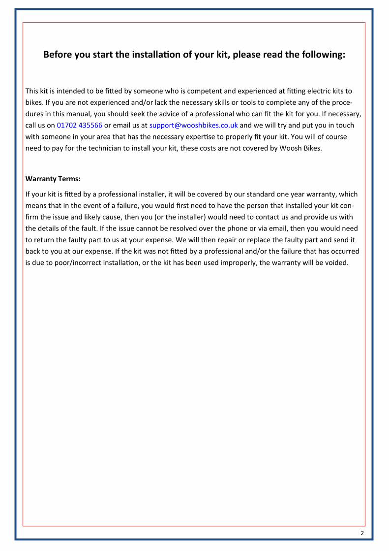
Before you start the installation of your kit, please read the following:
This kit is intended to be fitted by someone who is competent and experienced at fitting electric kits to
bikes. If you are not experienced and/or lack the necessary skills or tools to complete any of the proce-
dures in this manual, you should seek the advice of a professional who can fit the kit for you. If necessary,
call us on 01702 435566 or email us at [email protected] and we will try and put you in touch
with someone in your area that has the necessary expertise to properly fit your kit. You will of course
need to pay for the technician to install your kit, these costs are not covered by Woosh Bikes.
Warranty Terms:
If your kit is fitted by a professional installer, it will be covered by our standard one year warranty, which
means that in the event of a failure, you would first need to have the person that installed your kit con-
firm the issue and likely cause, then you (or the installer) would need to contact us and provide us with
the details of the fault. If the issue cannot be resolved over the phone or via email, then you would need
to return the faulty part to us at your expense. We will then repair or replace the faulty part and send it
back to you at our expense. If the kit was not fitted by a professional and/or the failure that has occurred
is due to poor/incorrect installation, or the kit has been used improperly, the warranty will be voided.

3
What’s in the box
Ensure that you have all the parts shown below before going any further, if there are any missing parts,
contact us on 01702 435566.
The kit comprises of a motor wheel, controller, pedelec sensor, display, frog-battery and battery-mounts.
As well as the items shown below, you will also have a selection of bolts/fixings, a motor wheel and a
battery charger—not pictured.

4
BEFORE fitting the kit to the bike
Plug everything in on your workbench and power up the kit, this will help to familiarise you with the vari-
ous parts that make up the kit, and also to ensure it works before fitting it to your bike. Refer to the in-
structions later in this manual to see which connections go where.
If the kit does not power up, contact us straight away on 01702 435566 or send an email (preferably with
pictures) to [email protected]
Assuming the kit powers up and the display comes on, you can then proceed to install the kit.
Fit the motor wheel first—this is normally very straightforward, but if there are any issues fitting the mo-
tor wheel, it’s best to discover them before installing the other parts of the kits.
5
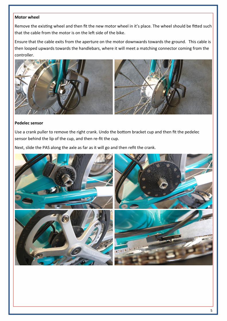
Motor wheel
Remove the existing wheel and then fit the new motor wheel in it’s place. The wheel should be fitted such
that the cable from the motor is on the left side of the bike.
Ensure that the cable exits from the aperture on the motor downwards towards the ground. This cable is
then looped upwards towards the handlebars, where it will meet a matching connector coming from the
controller.
Pedelec sensor
Use a crank puller to remove the right crank. Undo the bottom bracket cup and then fit the pedelec
sensor behind the lip of the cup, and then re-fit the cup.
Next, slide the PAS along the axle as far as it will go and then refit the crank.

6
Battery mounting
The mounting for the battery fits where the luggage block would normally be. If you have a luggage block,
remove it before you go any further.
The parts shown below-left must be fitted first. Use the two M5 button bolts to secure both of the parts
to the frame of the bike, as shown below-right.
The parts to be fitted next are shown below-left. Drop the white into the rear of the black casing, and feed
the four M5 cross-head bolts through the metal support from the other side, and then secure it to the
bike. The round opening in the side of the black plastic should be on the left as you look at the bike (the
right side if you were sitting on the bike).
When tightening these four bolts, tighten them a little each and go around each of them until they are all
tight. Don’t tighten one fully and move on to the next, tighten each of them gradually.

7
Battery mounting cont…
The next part of the battery mounting is now bolted to the other half already on the bike. There six nuts
and bolts for this, that are fitted along the top and bottom edge, bolts through the front, nuts on the
back.
The lock that is fitted to this has been deliberately left loose as it’s easier to fit this part of the casing with
it like this. Don’t forget to tighten the two bolts to properly secure the lock in place when you’re done
tightening the other six nuts/bolts.
Ensure that the moulded plug it sitting in the correct position before fitting the two halves together—see
below-right.
Display
The LCD would normally be fitted on the left as shown below. Use a 3mm allen key to release the clamp,
and then tighten to secure in position. The bolt is accessed from the underside of the display.
DO NOT FIT THE BATTERY AT THIS STAGE
8
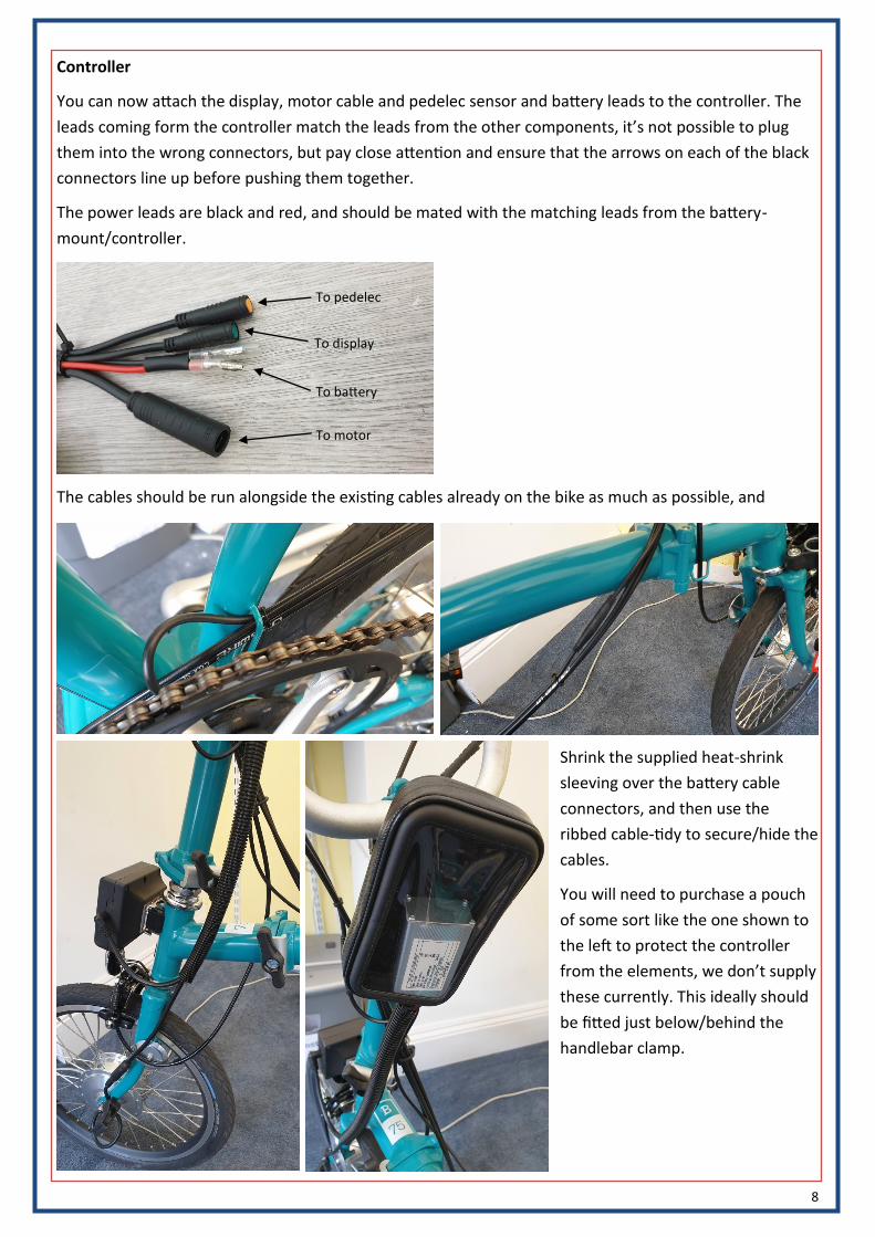
Controller
You can now attach the display, motor cable and pedelec sensor and battery leads to the controller. The
leads coming form the controller match the leads from the other components, it’s not possible to plug
them into the wrong connectors, but pay close attention and ensure that the arrows on each of the black
connectors line up before pushing them together.
The power leads are black and red, and should be mated with the matching leads from the battery-
mount/controller.
To pedelec
To display
To battery
To motor
The cables should be run alongside the existing cables already on the bike as much as possible, and
Shrink the supplied heat-shrink
sleeving over the battery cable
connectors, and then use the
ribbed cable-tidy to secure/hide the
cables.
You will need to purchase a pouch
of some sort like the one shown to
the left to protect the controller
from the elements, we don’t supply
these currently. This ideally should
be fitted just below/behind the
handlebar clamp.

9
Using the kit
Slide the battery in place (from left to right) on to the battery mount, and then use the key turning it
clockwise to lock it in position. Make sure the battery is properly secure before riding the bike.
The on/off switch for the battery is located at the top-rear of the unit.
The charging socket is also on the rear of the unit, on the opposite side to the on/off switch. The battery
can be charged on or off of the bike
The battery has a meter showing the remaining capacity, and a light which would normally be used when
the battery is fitted to the rear of a bike. To see the state of the battery, press the ‘Voltage’ button, and to
switch the light on/off, press the light button. The light will cycle from Off > On > Flashing > Off.
The meter showing the remaining battery capacity is made up of several LED’s, they are mostly green but
there is a single red LED. This red LED is always red and cannot change colour. It is like this to indicate that
if the red LED is the only one lit, the battery is almost completely flat, and requires charging.
10
Battery care:
Some care is needed to ensure that the battery performs at its best and lasts as long as possible. All
batteries age over time, and the way that they age is that the range you can achieve will gradually de-
crease. Follow the instructions below to ensure your battery performs as well as possible for as long as
possible. Charge the battery once or twice per week or more as needed.
Do NOT charge the battery in extremely cold conditions. The battery can be easily removed from the bike
and charged whilst off the bike.
If the battery is not in regular use i.e. over the winter, you should charge the battery to around two thirds
full, and then charge it for 5-10 minutes every three to four weeks. When the bike is to be put back into
service, fully charge the battery as normal. General battery care:
Do not attempt to open the outer casing of the battery.
Do not attempt to repair the battery.
Do not immerse the battery in water.
Keep the battery away from children.
Do not drop, pierce or otherwise damage the battery.
Ensure the battery is not exposed to temperatures above 55 degrees Celsius or extreme humidity.
Do not use the bike in an environment where temperatures are below -5 degrees Celsius.
Lithium batteries do not perform at their best during the winter months, and so the range may vary from
one season to another.
Charging the battery:
Plug the charger lead into the socket on the rear of the battery, then plug mains cable into the socket and
switch it on. While the battery is charging, the LED on the charger will glow RED, when charging is com-
plete, the LED will go GREEN. If the charger is on but not attached to the battery, the LED will also be
GREEN. If you experience a sudden drop in capacity, run the battery down quite low, then fully charge it.
Once full, leave the charger switched on and connected to the battery for a further two hours. This will
help to balance the cells internally and restore normal operation.
11
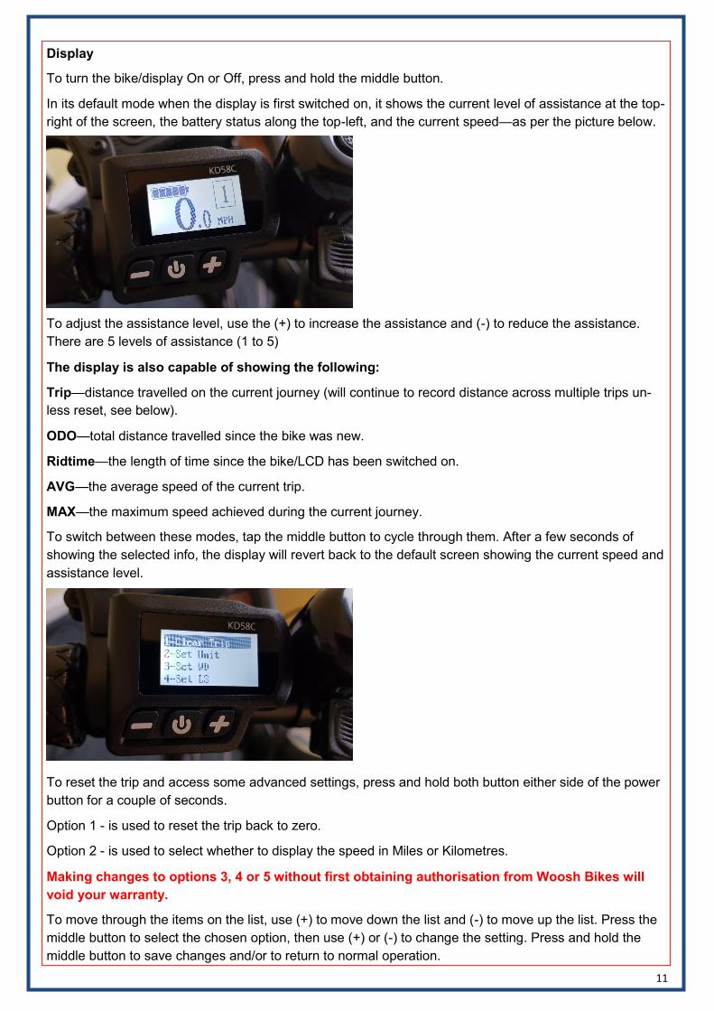
Display
To turn the bike/display On or Off, press and hold the middle button.
In its default mode when the display is first switched on, it shows the current level of assistance at the top-
right of the screen, the battery status along the top-left, and the current speed—as per the picture below.
To adjust the assistance level, use the (+) to increase the assistance and (-) to reduce the assistance.
There are 5 levels of assistance (1 to 5)
The display is also capable of showing the following:
Trip—distance travelled on the current journey (will continue to record distance across multiple trips un-
less reset, see below).
ODO—total distance travelled since the bike was new.
Ridtime—the length of time since the bike/LCD has been switched on.
AVG—the average speed of the current trip.
MAX—the maximum speed achieved during the current journey.
To switch between these modes, tap the middle button to cycle through them. After a few seconds of
showing the selected info, the display will revert back to the default screen showing the current speed and
assistance level.
To reset the trip and access some advanced settings, press and hold both button either side of the power
button for a couple of seconds.
Option 1 - is used to reset the trip back to zero.
Option 2 - is used to select whether to display the speed in Miles or Kilometres.
Making changes to options 3, 4 or 5 without first obtaining authorisation from Woosh Bikes will
void your warranty.
To move through the items on the list, use (+) to move down the list and (-) to move up the list. Press the
middle button to select the chosen option, then use (+) or (-) to change the setting. Press and hold the
middle button to save changes and/or to return to normal operation.

12
© 2019 Woosh Bikes Limited
Woosh Support:
Our contact details are below.
It can sometimes be useful to see the issue you have, so if possible, email a couple of photos illustrating
the problem and we’ll normally get back to you within an hour or two (on weekdays).
Support staff are not available at the weekends, though if you send an email, it will normally be read and
replied to on the following Monday (except on bank holidays).
Email: [email protected]
Telephone: 01702 435566