ROME DEUTSCHLAND DISTRIBUTION
70
Transcript of ROME DEUTSCHLAND DISTRIBUTION

www.tecnikabel.com
PRODUCTION
TK CHINA Cables & ConnectorsFactory Premises Co., Ltd No. 7111 North Dongting RoadTaicang Economy Development AreaTaicang City, Jiangsu Province, ChinaTel. +8617751210891
DISTRIBUTION
TECNIKABEL ME JLT3008 Mazaya Business AvenueJumeirah Lake TowersDubai, UAETel. +9714 4230877
MIDDLE EAST
TECNIKABEL ASIA PTE LTD11 Tuas CresSINGAPORE 638705Tel. +65 6909 3710
ASIA-PACIFIC
HEADQUARTERVOLPIANOVia Brandizzo, 24310088 Volpiano (Turin) ItalyTel. +39 011 9951997Fax +39 011 9953062www.tecnikabel.com
PRODUCTION PLANTSVOLPIANOVia Brandizzo, 24310088 Volpiano (Turin) Italy
ALMESEVia Rivera, 10010040 Almese (Turin) Italy
USA
TECNIKABEL ROMEVia Casali delle Cornacchiole, 15400178 Roma ItalyTel. +39 06 5099 2552 Fax +39 06 5051 4022
ROME
DEUTSCHLANDTK DEUTSCHLAND GmbHHerdewerg 883623 Steingau, GERMANYTel. +49 9421 9744222
BRANCH OFFICES
TECNIKABEL USA638 Spartanburg Hwy Suite 70 #325Hendersonville NC 28792Tel. +1 (828) 845-4180


The trend in automation applications is to increase motion control and data transmission simultaneously. The quantity of data and the speed at which it is distributed has been rising significantly. The demand for reliability of the signal and power transmission has increased at the same time.
This leads to increased complexity of cabling system that must perform in harsh industrial environments. Cables must perform in static as well as dynamic, continuously moving application and transmit power and data reliable even in applications with high electrical interference or mechanical stresses on the cable.
Tecnikabel is a specialist in providing cables that can handle motion in several axis at high acceleration while providing a high number of bending cycles.
Our automation cables are designed for use in the harshest industrial applications such as:• food processing and packaging machines• machine tools• wood working machines• glass making machines• conveyor and material handling technology• robotics
INTRODUCTION
PRODUCT LINES
GREEN ENERGY

TECNIKABELis focused on constant product innovation to get
competitive advantages with endless commitment to
research and development.
PRODUCTION
FINAL INSPECTIONS
LABORATORY TESTS
MATERIALS RESEARCH AND DEVELOPMENT
Updated production systems, stringent process
procedures and expert operators carry out our production
with efficiency and flexibility.
In 30 years of activity, we produced more than 26.000
different types of cables.
At the end of every production process each cable is
checked for its electrical and physical performances for a
complete compliance to customer specifications.
We submit our cables to the most severe tests, simulating
critical applications. In addition to the tests required by
current norms, we continuously invest in equipment for
mechanical and electrical testing, steadily increase the
standard performance of our cables.
Our thirty year experience took us to carry on research of
new materials in order to improve performances, costs
and fulfill the standards required by our customers.
4
QUALITY SYSTEM
Since 1978, constant commitment to Quality has awarded Tecnikabel approval
from American and European Authorities, complying with the most demanding
international manufacturing and quality standards.
LPS BS 6387:2013Ce rt /LPCB ref . 1352
5

INDEX
TK-FF390 SERIES CABLES FOR HIGH DYNAMIC APPLICATION ............................................................7
TK-FF390 SINGLE CORE UNSHIELDED AND SHIELDED CABLE ...............................................................8
TK-FF390 MULTICORE/MULTIPAIR CONTROL AND SIGNAL CABLE UNSHIELDED AND SHIELDED ......10
TK-FF390 MULTICORE CONTROL AND POWER CABLE UNSHIELDED AND SHIELDED ..........................14
TK-FF390 SERVOMOTOR POWER CABLE SHIELDED 0.6/1KV .................................................................22
HYBRID SERVO CABLE SHIELDED 0.6/1KV ...............................................................................................24
TK-FF390 ENCODER AND RESOLVER CABLE ............................................................................................26
TK-FF390 BUS CABLE - PROFIBUS L2 DP-FIP ...........................................................................................30
TK-FF390 BUS CABLE - CANOPEN - CANBUS ...........................................................................................32
TK-FF390 BUS CABLE - DEVICENET DROP AND TRUNK ..........................................................................34
TK-FF390 BUS CABLE - INTERBUS ............................................................................................................36
TK-FF390 ETHERNET – PROFINET/ETHERCAT CATEGORY 5E ...........................................................38
TK-FF390 ETHERNET CATEGORY 6 ...........................................................................................................40
TK-FF390 ETHERNET CATEGORY 7 ............................................................................................................42
RESEARCH & DEVELOPMENT ...................................................................................................................45
ELECTRIC/ELECTRONIC TESTS ..................................................................................................................46
PHYSICAL/CHEMICAL TESTS .....................................................................................................................47
MECHANICAL/DYNAMIC TESTS .................................................................................................................48
TECHNICAL INFORMATIONS ......................................................................................................................52
LOW CAPACITANCE POWER CABLES ........................................................................................................60
EXCERPT FROM NORM IEC 60204-1 ..........................................................................................................60
CABLE IDENTIFICATION TO DIN 47100 ......................................................................................................64
INSTRUCTIONS ...........................................................................................................................................65
GUIDELINES FOR CHOOSING THE RIGHT SHIELD IN YOUR CABLE .........................................................66
6

TK - FF300
FOR HIGH DYNAMIC APPLICATI
ON, PUR OIL RESISTANT,
UL/CSA APPROVALS, HALOGEN
FREE
Product description and applicationSingle-core and multicore cables for dynamic installations built in compliance with UL and CSA standards to satisfy the highest performance levels required by automation system and machine tool makers and for some applications aboard industrial robots. The most modern materials and features are used in TK FF390® to obtain small dimensions, allowing for use in bending-torsion, with the best price/performance ratio. Use in high dynamic installations is guaranteed with temperatures down to -40°C.
The outer sheath in Polyurethane provides good resistance to the most aggressive cutting and industrial oils, chemical substances typically found in industrial environments, and UV rays.
Our cables also meet the mandatory cleaning and hygiene requirements that exists for example in food and beverage applications. This was proven through a certification test by ECOLAB® – the world leader in Hygiene in technology and services for everything related to ecological safety.
TK - FF390
These images are solely for illustrative purposes 7

TKFF390-SERIES CABLES FOR HIGH DYNAMIC APPLICATIONs PUR OIL RESISTANT, UL/CSA APPROVAL, HALOGEN FREETK-FF390-SINGLE CORE UNSHIELDED AND SHIELDED CABLE
CABLE SPECIFICATIONS
ConductorCEI 20-29 Class 6 – IEC 60228 Class 6 – VDE 0295 Class 6
Overall Shield (optional)Tinned Copper Coverage ≥ 85% according to EMC 89/336 ©
InsulationPolyolefin (UL-CSA Standards)
Sheath La tua posizionePolyurethane 11Y (UL-CSA Standards)
Core identificationBlack (other colours available upon request)
Outer jacket colourBlack Ral 9005 according to DESINA colour chart page 163, other colours available upon request
TECHNICAL DATA
Operating voltage1000V
Maximum Acceleration50 m/s²
Test voltage3000V a.c.
Maximum Chain length15 m (horizontal)
Temperature range-40°C ÷ +90°C
Flex life5.000.000 cycles tested
Bending Radius5 x Ø (Static Installation)7.5 x Ø (1.5÷16mm² / Dynamic installation)10 x Ø (25÷240mm² / Dynamic Installation)
TorsionPlease contact our technical support office
Maximum Speed300 m/min
Maximum Pulling Force20N/mm² (dynamic use) or 50N/mm² (static use)
REFERENCE STANDARDS
Cable according to UL758, UL1581 and CSA C22.2 210.2UL 90°C 1000V -Style 11773 – CSA AWM I/II A/B 90°C 1000V
Hydrocarbons and Oil ResistanceUL 1581 – VDE 0472 part 803 A/B
Flame RetardantCEI 20-35 – EN50265 – IEC 60332-1 – UL VW-1 – CSA FT1
Water ResistanceUL 1581 – IEC 60811
Halogen FreeUL 1581 – VDE 0472 part 803 A/B
EC Directives Product compliant with Low Voltage Regulation 72/33/EEC
Directive EMC 2014/30/EU ElectromagneticCompatibility
European Directives 2011/65/CE (RoHS - Reduction of Hazardous Substances) and 2002/96/CE (WEEE – Waste from Electrical and Electronic Equipment)8

TK-FF390-SINGLE CORE UNSHIELDED AND SHIELDED CABLE
MAIN FEATURES
SINGLE CORE 90°C 1000V
SINGLE CORE SHIELDED 90°C 1000V
TECNIKABEL CODE DESCRIPTIONØ NOMINAL
(mm)COPPER WEIGHT
(Kg/Km)CABLE WEIGHT
(Kg/Km)
270TKFF39006 1x6 mm² 7 58 96.6280TKFF39006 1x10 mm² 8.3 96 148285TKFF39006 1x16 mm² 9.6 154 216290TKFF39006 1x25 mm² 11.2 240 321293TKFF39006 1x35 mm² 12.7 336 454295TKFF39006 1x50 mm² 15 480 625297TKFF39006 1x70 mm² 16.6 672 799298TKFF39006 1x95 mm² 19.4 912 1094299TKFF39006 1x120 mm² 22.6 1152 134529DTKFF39006 1x150 mm² 23.8 1440 171929FTKFF39006 1x185 mm² 25.3 1776 202229ITKFF39006 1x240 mm² 28.5 2304 2514
TECNIKABEL CODE DESCRIPTIONØ NOMINAL
(mm)COPPER WEIGHT
(Kg/Km)CABLE WEIGHT
(Kg/Km)
570TKFF39006 (1x6 mm²)H2 7.5 78 121.4580TKFF39006 (1x10 mm²)H2 8.7 122 179585TKFF39006 (1x16 mm²)H2 10.2 181 253590TKFF39006 (1x25 mm²)H2 11.8 272 366593TKFF39006 (1x35 mm²)H2 13.4 401 495595TKFF39006 (1x50 mm²)H2 15.6 579 682597TKFF39006 (1x70 mm²)H2 17.4 766 869598TKFF39006 (1x95 mm²)H2 20.4 1009 1201599TKFF39006 (1x120 mm²)H2 23.5 1272 148959DTKFF39006 (1x150 mm²)H2 24.6 1705 172259FTKFF39006 (1x185 mm²)H2 26.3 2095 228359ITKFF39006 (1x240 mm²)H2 29.5 2510 2697
9

TKFF390-SERIES CABLES FOR HIGH DYNAMIC APPLICATIONs PUR OIL RESISTANT, UL/CSA APPROVAL, HALOGEN FREETKFF390-MULTICORE/MULTIPAIR CONTROL AND SIGNAL CABLE UNSHIELDED AND SHIELDED
CABLE SPECIFICATIONS
ConductorCEI 20-29 Class 6 – IEC 60228 Class 6 – VDE 0295 Class 6
Overall Shield (optional)Tinned Copper Coverage ≥ 85% according to EMC 89/336 ©
InsulationPolyolefin (UL-CSA Standards)
SheathPolyurethane 11Y (UL-CSA Standards)
Core identificationDIN 47100
Outer jacket colourGrey Ral 7040 according to DESINA colour chart page 163, other colours available upon request
TECHNICAL DATA
Operating voltage300V
Temperature range-40°C ÷ +90°C
Test voltage2000 V a.c.
Maximum Pulling Force20N/mm² (dynamic use) or 50N/mm² (static use)
TK-FF390≤ 12 conductors : concentric conductors> 12 conductors : in bundle
TK-FF390LFrom 16 to 25 conductors in concentric layers
Bending Radius5 x Ø (Static Installation)7.5 x Ø (Dynamic Installation)
Bending Radius5 x Ø (Static Installation)7.5 x Ø (Dynamic Installation)
Maximum Speed300 m/min
Maximum Speed240 m/min
Maximum Acceleration50 m/s²
Maximum Acceleration30 m/s²
Maximum Chain length15 m (horizontal)
Maximum Chain length15 m (horizontal)
Flex life5.000.000 cycles tested
Flex life5.000.000 cycles tested
TorsionPlease contact our technical support office
TorsionPlease contact our technical support office
European Directives 2011/65/CE (RoHS - Reduction of Hazardous Substances) and 2002/96/CE (WEEE – Waste from Electrical and Electronic Equipment)10

TKFF390-MULTICORE/MULTIPAIR CONTROL AND SIGNAL CABLE UNSHIELDED AND SHIELDED
MAIN FEATURES
UNSHIELDED MULTICORE CONTROL AND SIGNAL
UNSHIELDED MULTICORE CONTROL AND SIGNAL
TECNIKABEL CODE DESCRIPTIONØ NOMINAL
(mm)COPPER WEIGHT
(Kg/Km)CABLE WEIGHT
(Kg/Km)
322TKFF39001 2x0.25mm² 4.2 4.8 21.4322TKFF39002 3x0.25mm² 4.8 7.5 25322TKFF39003 4x0.25mm² 4.9 10 29.4322TKFF39004 5x0.25mm² 5.6 12.5 34.1322TKFF39005 7x0.25mm² 6.4 17.5 42.5322TKFF39006 12x0.25mm² 6.9 29 56322TKFF39007 16x0.25mm² 8.7 37 82322TKFF39008 18x0.25mm² 9.8 45 90.2322TKFF39009 25x0.25mm² 10.9 63 119322TKFF39010 30x0.25mm² 12 72 107322TKFF39011 36x0.25mm² 13.2 86 163
TECNIKABEL CODE DESCRIPTIONØ NOMINAL
(mm)COPPER WEIGHT
(Kg/Km)CABLE WEIGHT
(Kg/Km)
325TKFF39001 2x0.35mm² 4.4 6.7 27325TKFF39002 3x0.35mm² 4.6 10 32325TKFF39003 4x0.35mm² 5 13 38325TKFF39004 5x0.35mm² 5.4 17 44325TKFF39005 7x0.35mm² 6.4 23.5 55325TKFF30006 12x0.35mm² 7.4 41 86325TKFF39007 16x0.35mm² 9.7 54 110325TKFF39008 18x0.35mm² 10.6 61 120325TKFF39009 25x0.35mm² 11.8 84 164325TKFF39010 30x0.35mm² 12.8 101 186325TKFF39011 36x0.35mm² 14.4 121 221
REFERENCE STANDARDS
Cable according to UL758, UL1581 and CSA C22.2 210.2UL 90°C 300V - Style 21209 – CSA AWM I/II A/B 90°C 300V, Cross-sectional area ≤ 0,50mm² (AWG21)
Hydrocarbons and Oil ResistanceUL 1581 – VDE 0472 part 803 A/B
Flame RetardantCEI 20-35 – EN50265 – IEC 60332-1 – UL VW-1 – CSA FT1
Water ResistanceUL 1581 – IEC 60811
Halogen FreeCEI 20-37 – IEC 60754-1 – EN 50267-2-1
EC Directives Product compliant with Low Voltage Regulation 72/33/EEC
Directive EMC 2014/30/EU ElectromagneticCompatibility
11

TKFF390-MULTICORE/MULTIPAIR CONTROL AND SIGNAL CABLE UNSHIELDED AND SHIELDED
MAIN FEATURES
SHIELDED MULTICORE CONTROL AND SIGNAL
SHIELDED MULTICORE CONTROL AND SIGNAL
TECNIKABEL CODE DESCRIPTIONØ NOMINAL
(mm)COPPER WEIGHT
(Kg/Km)CABLE WEIGHT
(Kg/Km)
522TKFF39001 2x0.25mm² 4.6 15 23522TKFF39002 3x0.25mm² 4.9 19 33.4522TKFF39003 4x0.25mm² 5.2 21 39.2522TKFF39004 5x0.25mm² 5.5 29 45.1522TKFF39005 7x0.25mm² 6.3 39 61522TKFF39006 12x0.25mm² 7.3 54 90522TKFF39007 16x0.25mm² 9.7 67 106522TKFF39013 18x0.25mm² 10.4 78 117522TKFF39009 25x0.25mm² 11.5 101 152522TKFF39010 30x0.25mm² 12.6 105 170522TKFF39011 36x0.25mm² 13.8 118 198
TECNIKABEL CODE DESCRIPTIONØ NOMINAL
(mm)COPPER WEIGHT
(Kg/Km)CABLE WEIGHT
(Kg/Km)
525TKFF39001 2x0.35mm² 4.8 16 34.6525TKFF39002 3x0.35mm² 5 20 40.2525TKFF39003 4x0.35mm² 5.4 25 48525TKFF39004 5x0.35mm² 5.8 29 55.2525TKFF39012 7x0.35mm² 6.8 38 68525TKFF39006 12x0.35mm² 7.8 65 112525TKFF39007 16x0.35mm² 10.3 83 137525TKFF39008 18x0.35mm² 11.2 88 149525TKFF39009 25x0.35mm² 12.4 122 195525TKFF39010 30x0.35mm² 13.4 142 221525TKFF39011 36x0.35mm² 15 165 257
12

TKFF390-MULTICORE/MULTIPAIR CONTROL AND SIGNAL CABLE UNSHIELDED AND SHIELDED
MAIN FEATURES
SHIELDED MULTICORE CONTROL AND SIGNAL
SHIELDED MULTICORE CONTROL AND SIGNAL
SHIELDED MULTICORE CONTROL AND SIGNAL
TECNIKABEL CODE DESCRIPTIONØ NOMINAL
(mm)COPPER WEIGHT
(Kg/Km)CABLE WEIGHT
(Kg/Km)
522TKFF39015 2x2x0.25mm² 6 23 45.7522TKFF39016 3x2x0.25mm² 6.4 28 55.1522TKFF39017 4x2x0.25mm² 6.8 38 72.2522TKFF39018 6x2x0.25mm² 8.2 52 96.2522TKFF39019 8x2x0.25mm² 9.4 64 116522TKFF39020 10x2x0.25mm² 10 75 137522TKFF39021 12x2x0.25mm² 10.5 89 156522TKFF39022 16x2x0.25mm² 11.8 107 189
TECNIKABEL CODE DESCRIPTIONØ NOMINAL
(mm)COPPER WEIGHT
(Kg/Km)CABLE WEIGHT
(Kg/Km)
525TKFF39015 2x2x0.35mm² 7 28 54.7525TKFF39016 3x2x0.35mm² 7.3 42 76.5525TKFF39017 4x2x0.35mm² 7.9 49 88.7525TKFF39018 6x2x0.35mm² 9.4 68 119525TKFF39019 8x2x0.35mm² 10.6 83 143525TKFF39020 10x2x0.35mm² 12 102 173525TKFF39021 12x2x0.35mm² 12.6 120 198525TKFF39022 16x2x0.35mm² 14 147 257
TECNIKABEL CODE DESCRIPTIONØ NOMINAL
(mm)COPPER WEIGHT
(Kg/Km)CABLE WEIGHT
(Kg/Km)
530TKFF39001 2x2x0.50mm² 7.8 45 79.3530TKFF39002 3x2x0.50mm² 7.9 58 103530TKFF39003 4x2x0.50mm² 8.5 73 118530TKFF39004 6x2x0.50mm² 10.4 101 160530TKFF39005 8x2x0.50mm² 11.4 124 194530TKFF39006 10x2x0.50mm² 13.5 150 236
13

TKFF390-SERIES CABLES FOR HIGH DYNAMIC APPLICATIONs PUR OIL RESISTANT, UL/CSA APPROVAL, HALOGEN FREETKFF390-MULTICORE CONTROL AND POWER CABLE UNSHIELDED AND SHIELDED
CABLE SPECIFICATIONS
ConductorCEI 20-29 Class 6 – IEC 60228 Class 6 – VDE 0295 Class 6
Overall Shield (optional)Tinned Copper Coverage ≥ 85% according to EMC 89/336 ©
InsulationPolyolefin (UL-CSA Standards)
SheathPolyurethane 11Y (UL-CSA Standards)
Core identificationBlack Numbered + Yellow/Green
Outer jacket colourGrey Ral 7040 according to DESINA colour chart page 163, other colours available upon request
TECHNICAL DATA
Operating voltage300V Cross-sectional area 0.5mm² (AWG21) ÷ 1.0mm² (AWG18)1000V Cross-sectional area ≥ 1.0mm² (AWG18)
Temperature range-40°C ÷ +90°C
Test voltage2000 Va.c. Cross-sectional area 0.5mm² (AWG21) ÷ 1.0mm² (AWG18)3000 Va.c. Cross-sectional area ≥ 1.0mm² (AWG18)
Maximum Pulling Force20N/mm² (dynamic use) or 50N/mm² (static use)
TK-FF390≤ 12 conductors : concentric conductors> 12 conductors : in bundle
TK-FF390LFrom 16 to 25 conductors in concentric layers
Bending Radius5 x Ø (Static Installation)7.5 x Ø (1.5÷16mm² / Dynamic installation)10 x Ø (25÷50mm² / Dynamic Installation)
Bending Radius5 x Ø (Static Installation)7.5 x Ø (1.5÷16mm² / Dynamic Installation)10 x Ø (25÷50mm² / Dynamic Installation)
Maximum Speed300 m/min
Maximum Speed240 m/min
Maximum Acceleration50 m/s²
Maximum Acceleration30 m/s²
Maximum Chain length15 m (horizontal)
Maximum Chain length15 m (horizontal)
Flex life5.000.000 cycles tested
Flex life5.000.000 cycles tested
TorsionPlease contact our technical support office
TorsionPlease contact our technical support office
European Directives 2011/65/CE (RoHS - Reduction of Hazardous Substances) and 2002/96/CE (WEEE – Waste from Electrical and Electronic Equipment)14

TKFF390-MULTICORE CONTROL AND POWER CABLE UNSHIELDED AND SHIELDED
REFERENCE STANDARDS
Cable according to UL758, UL1581 and CSA C22.2 210.2UL 90°C 300V -Style 21209 – CSA AWM I/II A/B 90°C 300V, Cross-sectional area 0,5mm² (AWG21 ) ÷ 1,0mm² (AWG18)UL 90°C 1000V - Style 21209 – CSA AWM I/II A/B 90°C 1000V, Cross-sectional area ≥ 1,0mm² (AWG18)
Hydrocarbons and Oil ResistanceUL 1581 – VDE 0472 part 803 A/B
According to NFPA 79-2018-Chapter 12.9 Water ResistanceUL 1581 – IEC 60811
Flame RetardantCEI 20-35 – EN50265 – IEC 60332-1 – UL VW-1 – CSA FT1
EC Directives Product compliant with Low Voltage Regulation 72/33/EEC
Halogen FreeCEI 20-37 – IEC 60754-1 – EN 50267-2-1
Directive EMC 2014/30/EU ElectromagneticCompatibility
15

MAIN FEATURES
UNSHIELDED MULTICORE CONTROL CABLES
UNSHIELDED MULTICORE CONTROL CABLES
TECNIKABEL CODE DESCRIPTIONØ NOMINAL
(mm)COPPER WEIGHT
(Kg/Km)CABLE WEIGHT
(Kg/Km)
330TKFF39001 2x0.50mm² 5 10 42.8330TKFF39002 3x0.50mm² 5.4 15 51.2330TKFF39003 4x0.50mm² 5.9 20 61.8330TKFF39004 5x0.50mm² 6.1 24 72.6330TKFF39005 7x0.50mm² 7.5 34 93.4330TKFF39006 12x0.50mm² 8.8 58 147330TKFF39007 18x0.50mm² 12 87 216330TKFF39008 25x0.50mm² 13.8 120 288330TKFF39009 34x0.50mm² 16.7 164 379330TKFF39010 41x0.50mm² 18.4 197 435
330TKFF390L1 18x0.50mm² 10 87 184330TKFF390L2 25x0.50mm² 12 120 245
TECNIKABEL CODE DESCRIPTIONØ NOMINAL
(mm)COPPER WEIGHT
(Kg/Km)CABLE WEIGHT
(Kg/Km)
340TKFF39001 2x1mm² 5.6 19 48.4340TKFF39002 3x1mm² 6.1 29 74.9340TKFF39003 4x1mm² 6.5 38 85.8340TKFF39004 5x1mm² 7.0 48 98.3340TKFF39005 7x1mm² 8.3 67 130340TKFF39006 12x1mm² 10.8 116 186340TKFF39007 18x1mm² 14.7 173 320340TKFF39008 25x1mm² 16.3 240 414340TKFF39009 34x1mm² 19.8 327 559
340TKFF390L1 18x1mm² 11.6 173 265340TKFF390L2 25x1mm² 14.5 240 402
TKFF390-MULTICORE CONTROL AND POWER CABLE UNSHIELDED AND SHIELDED
16

TKFF390-MULTICORE CONTROL AND POWER CABLE UNSHIELDED AND SHIELDED
MAIN FEATURES
SHIELDED MULTICORE CONTROL CABLES
SHIELDED MULTICORE CONTROL CABLES
TECNIKABEL CODE DESCRIPTIONØ NOMINAL
(mm)COPPER WEIGHT
(Kg/Km)CABLE WEIGHT
(Kg/Km)
530TKFF39007 2x0.50mm² 5.7 30 50.1530TKFF39008 3x0.50mm² 5.8 39 61.5530TKFF39009 4x0.50mm² 6.3 46 83.5530TKFF39010 5x0.50mm² 6.7 54 94.7530TKFF39011 7x0.50mm² 8 70 118530TKFF39012 12x0.50mm² 9.4 105 181530TKFF39013 18x0.50mm² 12.6 153 253530TKFF39014 25x0.50mm² 14.4 202 330530TKFF39015 34x0.50mm² 17.3 277 458530TKFF39016 41x0.50mm² 19.2 328 549
530TKFF390L1 18x0.50mm² 10.6 153 215530TKFF390L2 25x0.50mm² 12.8 202 280
TECNIKABEL CODE DESCRIPTIONØ NOMINAL
(mm)COPPER WEIGHT
(Kg/Km)CABLE WEIGHT
(Kg/Km)
540TKFF39013 2x1mm² 6.1 42 67.9540TKFF39014 3x1mm² 6.4 56 85.5540TKFF39015 4x1m² 7.0 68 102540TKFF39004 5x1mm² 7.5 79 113540TKFF39005 7x1mm² 8.7 99 150540TKFF39006 12x1mm² 11.4 175 240540TKFF39007 18x1mm² 15.4 196 375540TKFF39008 25x1mm² 16.9 285 476540TKFF39009 34x1mm² 20.7 450 688
540TKFF390L1 18x1mm² 12.2 240 307540TKFF390L2 25x1mm² 15.2 285 458
17

TKFF390-MULTICORE CONTROL AND POWER CABLE UNSHIELDED AND SHIELDED
MAIN FEATURES
UNSHIELDED MULTICORE CONTROL AND POWER CABLES
UNSHIELDED MULTICORE CONTROL AND POWER CABLES
UNSHIELDED MULTICORE CONTROL AND POWER CABLES
TECNIKABEL CODE DESCRIPTIONØ NOMINAL
(mm)COPPER WEIGHT
(Kg/Km)CABLE WEIGHT
(Kg/Km)
345TKFF39001 2x1.5mm² 7 29 68.8345TKFF39002 3x1.5mm² 7.7 43 85345TKFF39003 4x1.5mm² 8.2 58 104345TKFF39004 5x1.5mm² 8.9 72 124345TKFF39005 7x1.5mm² 11 101 162345TKFF39006 12x1.5mm² 13 173 267345TKFF39007 18x1.5mm² 19.2 260 384345TKFF39008 25x1.5mm² 21.8 360 529345TKFF39009 34x1.5mm² 26.5 490 709
345TKFF390L1 18x1.5mm² 15.2 260 326345TKFF390L2 25x1.5mm² 19.2 360 450
TECNIKABEL CODE DESCRIPTIONØ NOMINAL
(mm)COPPER WEIGHT
(Kg/Km)CABLE WEIGHT
(Kg/Km)
355TKFF39001 2x2.5mm² 8.6 48 93.4355TKFF39002 3x2.5mm² 9.2 72 117355TKFF39003 4x2.5mm² 10 96 145355TKFF39004 5x2.5mm² 11 120 175355TKFF39005 7x2.5mm² 13.5 168 231355TKFF39006 12x2.5mm² 16 288 385355TKFF39007 18x2.5mm² 24.6 432 554355TKFF39008 25x2.5mm² 28 600 781
355TKFF390L1 18x2.5mm² 19 432 471355TKFF390L2 25x2.5mm² 24.5 600 750
TECNIKABEL CODE DESCRIPTIONØ NOMINAL
(mm)COPPER WEIGHT
(Kg/Km)CABLE WEIGHT
(Kg/Km)
365TKFF39001 2x4mm² 10.2 77 134365TKFF39002 3x4mm² 11 116 171365TKFF39003 4x4mm² 11.8 154 214365TKFF39004 5x4mm² 13 192 263365TKFF39005 7x4mm² 15.6 269 355
18

TKFF390-MULTICORE CONTROL AND POWER CABLE UNSHIELDED AND SHIELDED
MAIN FEATURES
UNSHIELDED MULTICORE CONTROL AND POWER CABLES
UNSHIELDED MULTICORE CONTROL AND POWER CABLES
UNSHIELDED MULTICORE CONTROL AND POWER CABLES
UNSHIELDED MULTICORE CONTROL AND POWER CABLES
TECNIKABEL CODE DESCRIPTIONØ NOMINAL
(mm)COPPER WEIGHT
(Kg/Km)CABLE WEIGHT
(Kg/Km)
370TKFF39001 4x6mm² 13.6 230 327370TKFF39002 5x6mm² 14.8 288 395370TKFF39003 7x6mm² 18.2 403 533
TECNIKABEL CODE DESCRIPTIONØ NOMINAL
(mm)COPPER WEIGHT
(Kg/Km)CABLE WEIGHT
(Kg/Km)
380TKFF39001 4x10mm² 17.8 354 527380TKFF39002 5x10mm² 18.8 480 645380TKFF39003 7x10mm² 23.5 672 882
TECNIKABEL CODE DESCRIPTIONØ NOMINAL
(mm)COPPER WEIGHT
(Kg/Km)CABLE WEIGHT
(Kg/Km)
385TKFF39001 4x16mm² 20.4 615 857385TKFF39002 5x16mm² 22.7 768 1041385TKFF39003 7x16mm² 28 1076 1385
TECNIKABEL CODE DESCRIPTIONØ NOMINAL
(mm)COPPER WEIGHT
(Kg/Km)CABLE WEIGHT
(Kg/Km)
390TKFF39001 4x25mm² 25.2 960 1315393TKFF39001 4x35mm² 30.5 1344 1865395TKFF39001 4x50mm² 36.6 1920 2866397TKFF39001 4x70mm² 39.4 2688 3561398TKFF39001 4x95mm² 45.6 3651 4713
19
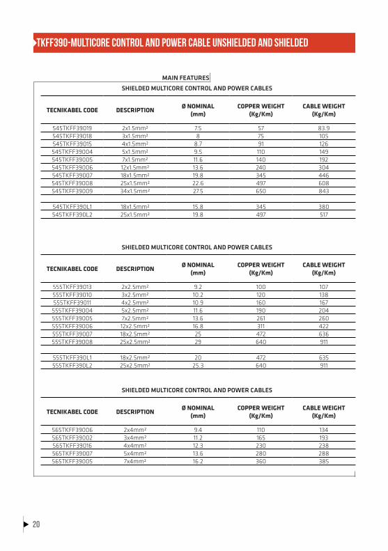
TKFF390-MULTICORE CONTROL AND POWER CABLE UNSHIELDED AND SHIELDED
MAIN FEATURES
SHIELDED MULTICORE CONTROL AND POWER CABLES
SHIELDED MULTICORE CONTROL AND POWER CABLES
SHIELDED MULTICORE CONTROL AND POWER CABLES
TECNIKABEL CODE DESCRIPTIONØ NOMINAL
(mm)COPPER WEIGHT
(Kg/Km)CABLE WEIGHT
(Kg/Km)
545TKFF39019 2x1.5mm² 7.5 57 83.9545TKFF39018 3x1.5mm² 8 75 105545TKFF39015 4x1.5mm² 8.7 91 126545TKFF39004 5x1.5mm² 9.5 110 149545TKFF39005 7x1.5mm² 11.6 140 192545TKFF39006 12x1.5mm² 13.6 240 304545TKFF39007 18x1.5mm² 19.8 345 446545TKFF39008 25x1.5mm² 22.6 497 608545TKFF39009 34x1.5mm² 27.5 650 843
545TKFF390L1 18x1.5mm² 15.8 345 380545TKFF390L2 25x1.5mm² 19.8 497 517
TECNIKABEL CODE DESCRIPTIONØ NOMINAL
(mm)COPPER WEIGHT
(Kg/Km)CABLE WEIGHT
(Kg/Km)
555TKFF39013 2x2.5mm² 9.2 100 107555TKFF39010 3x2.5mm² 10.2 120 138555TKFF39011 4x2.5mm² 10.9 160 167
555TKFF39004 5x2.5mm² 11.6 190 204555TKFF39005 7x2.5mm² 13.6 261 260555TKFF39006 12x2.5mm² 16.8 311 422555TKFF39007 18x2.5mm² 25 472 636555TKFF39008 25x2.5mm² 29 640 911
555TKFF390L1 18x2.5mm² 20 472 635555TKFF390L2 25x2.5mm² 25.3 640 911
TECNIKABEL CODE DESCRIPTIONØ NOMINAL
(mm)COPPER WEIGHT
(Kg/Km)CABLE WEIGHT
(Kg/Km)
565TKFF39006 2x4mm² 9.4 110 134565TKFF39002 3x4mm² 11.2 165 193565TKFF39016 4x4mm² 12.3 230 238565TKFF39007 5x4mm² 13.6 280 288565TKFF39005 7x4mm² 16.2 360 385
20

TKFF390-MULTICORE CONTROL AND POWER CABLE UNSHIELDED AND SHIELDED
MAIN FEATURES
SHIELDED MULTICORE CONTROL AND POWER CABLES
SHIELDED MULTICORE CONTROL AND POWER CABLES
SHIELDED MULTICORE CONTROL AND POWER CABLES
SHIELDED MULTICORE CONTROL AND POWER CABLES
TECNIKABEL CODE DESCRIPTIONØ NOMINAL
(mm)COPPER WEIGHT
(Kg/Km)CABLE WEIGHT
(Kg/Km)
570TKFF39005 4x6mm² 14.2 282 352570TKFF39008 5x6mm² 15.5 340 408570TKFF39007 7x6mm² 19.2 450 573
TECNIKABEL CODE DESCRIPTIONØ NOMINAL
(mm)COPPER WEIGHT
(Kg/Km)CABLE WEIGHT
(Kg/Km)
580TKFF39007 4x10mm² 18.6 485 566580TKFF39008 5x10mm² 19.6 562 697580TKFF39004 7x10mm² 24.5 796 985
TECNIKABEL CODE DESCRIPTIONØ NOMINAL
(mm)COPPER WEIGHT
(Kg/Km)CABLE WEIGHT
(Kg/Km)
585TKFF39007 4x16mm² 21.5 723 858585TKFF39008 5x16mm² 23.5 889 1086585TKFF39004 7x16mm² 29 1240 1439
TECNIKABEL CODE DESCRIPTIONØ NOMINAL
(mm)COPPER WEIGHT
(Kg/Km)CABLE WEIGHT
(Kg/Km)
585TKFF39007 4x25mm² 26.2 1090 1442593TKFF39007 4x35mm² 31.8 1536 2046595TKFF39007 4x50mm² 37.6 2381 3073597TKFF39001 4x70mm² 40.5 2921 3801598TKFF39001 4x95mm² 46.8 3950 4992
21

REFERENCE STANDARDS
Cable according to UL758, UL1581 and CSA C22.2 210.2UL 90°C 1000V - Style 21209 – CSA AWM I/II A/B 90°C 1000V
Hydrocarbons and Oil ResistanceUL 1581 – VDE 0472 part 803 A/B
According to NFPA 79-2018-Chapter 12.9 Water ResistanceUL 1581 – IEC 60811
Flame RetardantCEI 20-35 – EN50265 – IEC 60332-1 – UL VW-1 – CSA FT1
EC Directives Product compliant with Low Voltage Regulation 72/33/EEC
Halogen FreeCEI 20-37 – IEC 60754-1 – EN 50267-2-1
Directive EMC 2014/30/EU ElectromagneticCompatibility
TKFF390-SERIES CABLES FOR HIGH DYNAMIC APPLICATIONs PUR OIL RESISTANT, UL/CSA APPROVAL, HALOGEN FREETKFF390-SERVOMOTOR POWER CABLE SHIELDED 0.6/1KV
CABLE SPECIFICATIONS
ConductorCEI 20-29 Class 6 – IEC 60228 Class 6 – VDE 0295 Class 6
Pairs Shield (where request)Tinned Copper Coverage ≥ 85% according to EMC 89/336 ©
InsulationPolyolefin (UL-CSA Standards)
Overall ShieldTinned Copper Coverage ≥ 85% according to EMC 89/336 ©
Core identificationBlack Numbered U/L1/C/L+, V/L2, W/L3/D/L-, Yellow/Green
SheathPolyurethane 11Y (UL-CSA Standards)
Pairs Identification (where request)One pair: black, white. Two pairs: Black Numbered 5÷6 and Black Numbered 7÷8
Outer jacket colourOrange Ral 2003 according to DESINA colour chart page 163, other colours available upon request
TECHNICAL DATA
Operating voltage1000V Cross-sectional area 1.0mm² (AWG18)
Maximum Speed300 m/min
Test voltage4000V a.c. Cross-sectional area 1.0mm² (AWG18)
Maximum Acceleration50 m/s²
Temperature range-40°C ÷ +90°C
Maximum Chain length15 m (horizontal)
Bending Radius5 x Ø (Static Installation)7.5 x Ø ( 1.5 – 16mm² / Dynamic Installation)10 x Ø ( 25 – 50mm² / Dynamic Installation)
Flex life5.000.000 cycles tested
TorsionPlease contact our technical support office
Maximum Pulling Force20N/mm² (dynamic use) or 50N/mm² (static use)
European Directives 2011/65/CE (RoHS - Reduction of Hazardous Substances) and 2002/96/CE (WEEE – Waste from Electrical and Electronic Equipment)22

TKFF390-SERVOMOTOR POWER CABLE SHIELDED 0.6/1KV
MAIN FEATURES
SERVO CABLES 90°C 1000V
SERVO CABLE 90°C 1000V
SERVO CABLES 90°C 1000V
TECNIKABEL CODE DESCRIPTIONØ NOMINAL
(mm)COPPER WEIGHT
(Kg/Km)CABLE WEIGHT
(Kg/Km)
545TKFF39001 (4G1.5)H2 8.7 83 131555TKFF39001 (4G2.5)H2 10.8 130 198565TKFF39001 (4G4)H2 12.2 193 276570TKFF39001 (4G6)H2 14 282 376580TKFF39001 (4G10)H2 17.6 450 567585TKFF39001 (4G16)H2 21.2 720 885590TKFF39001 (4G25)H2 25 1003 1314593TKFF39001 (4G35)H2 28.8 1514 2146595TKFF39001 (4G50)H2 33.9 2167 2992
TECNIKABEL CODE DESCRIPTIONØ NOMINAL
(mm)COPPER WEIGHT
(Kg/Km)CABLE WEIGHT
(Kg/Km)
545TKFF39016 [4G1.5 + (2x1.5)H2]H2 11.6 149 221555TKFF39009 [4G2.5 + (2x1.5)H2]H2 13 193 264565TKFF39004 [4G4 + (2x1.5)H2]H2 14.7 255 315570TKFF39002 [4G6 + (2x1.5)H2]H2 16.2 339 480580TKFF39002 [4G10 + (2x1.5)H2]H2 19.7 526 774585TKFF39002 [4G16 + (2x1.5)H2]H2 23.6 773 1043590TKFF39002 [4G25 + (2x1.5)H2]H2 27.4 1190 1567593TKFF39002 [4G35 + (2x1.5)H2]H2 31 1590 1978595TKFF39002 [4G50 + (2x1.5)H2]H2 34.5 2240 2766
TECNIKABEL CODE DESCRIPTIONØ NOMINAL
(mm)COPPER WEIGHT
(Kg/Km)CABLE WEIGHT
(Kg/Km)
540TKFF39003 [4G1 + 2x(2x0.75)H2]H2 12.2 137 216545TKFF39003 [4G1.5 + 2x(2x0.75)H2]H2 12.8 155 259555TKFF39012 [4G2.5 + 2x(2x1)H2]H2 14.2 220 320565TKFF39003 [4G4 + (2x1) + (2x1.5)H2]H2 16.3 293 439570TKFF39003 [4G6 + (2x1) + (2x1.5)H2]H2 18 372 594580TKFF39003 [4G10 + (2x1) + (2x1.5)H2]H2 21.8 570 845585TKFF39003 [4G16 + 2x (2x1.5)H2]H2 25.5 830 1231590TKFF39003 [4G25 + 2x (2x1.5)H2]H2 30 1213 1615593TKFF39003 [4G35 + 2x (2x1.5)H2]H2 31.2 1598 2022
23

CABLES FOR HIGH DYNAMIC APPLICATIONs PUR OIL RESISTANT, UL/CSA APPROVAL, HALOGEN FREEHYBRID SERVO CABLE SHIELDED 0.6/1KV
CABLE SPECIFICATIONS
ConductorCEI 20-29 Class 6 – IEC 60228 Class 6 – VDE 0295 Class 6
Overall ShieldTinned Copper Coverage ≥ 85% according to EMC 89/336 ©
InsulationPolyolefin (UL-CSA Standards)
SheathPolyurethane 11Y (UL-CSA Standards)
Core identificationBlack Numbered U/L1/C/L+, V/L2, W/L3/D/L-, Yellow/GreenPairs IdentificationOne pair: blue, white. Two pairs: black, white and blue, white
Outer jacket colourOrange Ral 2003 according to DESINA colour chart page 163, other colours available upon request
Pairs ShieldTinned Copper Coverage ≥ 85% according to EMC 89/336 ©
TECHNICAL DATA
Operating voltage1000V
Maximum Acceleration50 m/s²
Test voltage4000V a.c.
Maximum Chain length15 m (horizontal)
Temperature range-40°C ÷ +90°C
Flex life5.000.000 cycles tested
Bending Radius5 x Ø (Static Installation)7.5 x Ø ( 1.5 – 16mm² / Dynamic Installation)
TorsionPlease contact our technical support office
Maximum Speed300 m/min
Maximum Pulling Force20N/mm² (dynamic use) or 50N/mm² (static use)
European Directives 2011/65/CE (RoHS - Reduction of Hazardous Substances) and 2002/96/CE (WEEE – Waste from Electrical and Electronic Equipment)24

TECNIKABEL CODE
DESCRIPTIONØ NOMINAL
(mm)
COPPER WEIGHT(Kg/Km)
CABLE WEIGHT(Kg/Km)
540TKFF39D02 [4G1+(2xAWG22)H2/H]H2 10.60 93 163545TKFF39D02 [4G1,5+(2xAWG22)H2/H]H2 11.20 113 194555TKFF39D02 [4G2,5+(2xAWG22)H2/H]H2 12.60 161 253565TKFF39D02 [4G4+(2xAWG22)H2/H]H2 14.00 222 325530TKFF39D01 [4G0,50+(2x0,50)ST+(2xAWG22)H2/H]H2 11.30 93 173540TKFF39D01 [4G1+(2x0,75)ST+(2xAWG24)H2/H]H2 11.90 113 201540TKFF39D03 [4G1+(2x0,75)ST+(2xAWG22)H2/H]H2 11.90 126 209545TKFF39D01 [4G1,5+(2x1)ST+(2xAWG22)H2/H]H2 12.80 145 238555TKFF39D01 [4G2,5+(2x1)ST+(2xAWG22)H2/H]H2 14.00 198 298565TKFF39D01 [4G4+(2x1)ST+(2xAWG22)H2/H]H2 15.80 265 388570TKFF39D01 [4G6+(2x1)ST+(2xAWG22)H2/H]H2 17.80 336 481580TKFF39D01 [4G10+(2x1,5)ST+(2xAWG22)H2/H]H2 21.00 532 736585TKFF39D01 [4G16+(2x1,5)ST+(2xAWG22)H2/H]H2 26.00 776 1099
HYBRID SERVO CABLE SHIELDED 0.6/1KV
DSL
MAIN FEATURES
REFERENCE STANDARDS
Cable according to UL758, UL1581 and CSA C22.2 210.2UL 90°C 1000V - Style 21209 – CSA AWM I/II A/B 90°C 1000V
Hydrocarbons and Oil ResistanceUL 1581 – VDE 0472 part 803 A/B
Flame RetardantCEI 20-35 – EN50265 – IEC 60332-1 – UL VW-1 – CSA FT1
Water ResistanceUL 1581 – IEC 60811
Halogen FreeCEI 20-37 – IEC 60754-1 – EN 50267-2-1
EC Directives Product compliant with Low Voltage Regulation 72/33/EEC
Directive EMC 2014/30/EU ElectromagneticCompatibility
...guaranteed up to 100 m...
25

TKFF390-SERIES CABLES FOR HIGH DYNAMIC APPLICATIONs PUR OIL RESISTANT, UL/CSA APPROVAL, HALOGEN FREETKFF390-ENCODER AND RESOLVER CABLE
CABLE SPECIFICATIONS
ConductorCEI 20-29 Class 6 – IEC 60228 Class 6 – VDE 0295 Class 6
Overall ShieldTinned Copper Coverage ≥ 85% according to EMC 89/336 ©
InsulationPolyolefin and/or Polyester (UL-CSA Standards)
SheathPolyurethane 11Y (UL-CSA Standards)
Core identificationMore informations are available upon request
Outer jacket colourGreen Ral 6018 according to DESINA colour chart page 163, other colours available upon request
TECHNICAL DATA
Operating voltage30 V or 300V
Maximum Acceleration50 m/s²
Test voltage1000V a.c. or 2000V a.c.
Maximum Chain length15 m (horizontal)
Temperature range- 40°C ÷ +90°C
Flex life5.000.000 cycles tested
Bending Radius5 x Ø (Static Installation)7.5 x Ø (Dynamic Installation)
TorsionPlease contact our technical support office
Maximum Speed300 m/min
Maximum Pulling Force20N/mm² (dynamic use) or 50N/mm² (static use)
REFERENCE STANDARDS
Cable according to UL758, UL1581 and CSA C22.2 210.2UL 90°C 300V -Style 21209 – CSA AWM I/II A/B 90°C 300V, or UL 90°C 30V -Style 20671 – CSA AWM I/II A/B 90°C 30V
Hydrocarbons and Oil ResistanceUL 1581 – VDE 0472 part 803 A/B
Flame RetardantCEI 20-35 – EN50265 – IEC 60332-1 – UL VW-1 – CSA FT1
Water ResistanceUL 1581 – IEC 60811
Halogen FreeCEI 20-37 – IEC 60754-1 – EN 50267-2-1
EC Directives Product compliant with Low Voltage Regulation 72/33/EEC
Directive EMC 2014/30/EU ElectromagneticCompatibility
European Directives 2011/65/CE (RoHS - Reduction of Hazardous Substances) and 2002/96/CE (WEEE – Waste from Electrical and Electronic Equipment)26

TKFF390-ENCODER AND RESOLVER CABLE
MAIN FEATURES
ANALOGIC/DIGITAL ENCODER SIGNAL TRANSMISSION - HEIDENHAIN
ANALOGIC/DIGITAL ENCODER SIGNAL TRANSMISSION - B&R
ANALOGIC/DIGITAL ENCODER SIGNAL TRANSMISSION - ELAU
ANALOGIC/DIGITAL ENCODER SIGNAL TRANSMISSION - CONTROL TECHNIQUES
TECNIKABEL CODE
DESCRIPTIONØ NOMINAL
(mm)
COPPER WEIGHT(Kg/Km)
CABLE WEIGHT(Kg/Km)
514TKFF39001 [4x2x0.14 + (4x0.14)H1 + 4x0.5]H2 8.6 70 102514TKFF39002 [3x(2x0.14)H1 + 2x(0.5)H1]H2 8.9 66 124514TKFF39003 (4x2x0.14 + 4x0.50)H2 9 51 106
514TKFF3901N [4x2x0.14 + (4x0.14)H1 + 4x0.5]H2 8.6 70 102514TKFF3902N [3x(2x0.14)H1 + 2x(0.5)H1]H2 8.9 66 124514TKFF3903N (4x2x0.14 + 4x0.50)H2 9 51 106
TECNIKABEL CODE
DESCRIPTIONØ NOMINAL
(mm)
COPPER WEIGHT(Kg/Km)
CABLE WEIGHT(Kg/Km)
514TKFF39012 (5x2x0.14 + 2x0.50)H2 7.9 42 73.2518TKFF39026 (3x2xAWG24)H2 6.5 27 52.4
TECNIKABEL CODE
DESCRIPTIONØ NOMINAL
(mm)
COPPER WEIGHT(Kg/Km)
CABLE WEIGHT(Kg/Km)
522TKFF39024 (3x2x0.25 + 2x0.50)H2 8.2 47 88522TKFF39025 3x(2x0.25)H2 8.0 74 150
TECNIKABEL CODE
DESCRIPTIONØ NOMINAL
(mm)
COPPER WEIGHT(Kg/Km)
CABLE WEIGHT(Kg/Km)
525TKFF39023 [(2x0.34)H + 6x2x0.32 + 2 x1)]H2 11 102 172512TKFF39002 (2x2xAWG26) H2 5.6 19 45
Note: outer sheath black
27

TKFF390-ENCODER AND RESOLVER CABLE
MAIN FEATURES
ANALOGIC/DIGITAL ENCODER SIGNAL TRANSMISSION - LENZE
ANALOGIC/DIGITAL ENCODER SIGNAL TRANSMISSION - YASKAWA
ANALOGIC/DIGITAL ENCODER SIGNAL TRANSMISSION - BOSCH REXROTH
ANALOGIC/DIGITAL ENCODER SIGNAL TRANSMISSION - SIEMENS
TECNIKABEL CODE
DESCRIPTIONØ NOMINAL
(mm)
COPPER WEIGHT(Kg/Km)
CABLE WEIGHT(Kg/Km)
514TKFF39007 3x(2x0.14)H2 + (2x0.50)H2 10 47 152514TKFF39008 4x(2x0.14)H2 + 2x(1)H2 11.5 70 229
TECNIKABEL CODE
DESCRIPTIONØ NOMINAL
(mm)
COPPER WEIGHT(Kg/Km)
CABLE WEIGHT(Kg/Km)
525TKFF39024 (2x2x0.34)H2 8.5 36 83.3
TECNIKABEL CODE
DESCRIPTIONØ NOMINAL
(mm)
COPPER WEIGHT(Kg/Km)
CABLE WEIGHT(Kg/Km)
522TKFF39027 (4x2x0.25 + 2x0.50)H2 8.7 65 111514TKFF39009 [4x2x0.14 + 4x1 + (4x0.14)H2]H2 9.7 93 165522TKFF39028 [3x(2x0.25)H2 + 3x0.25 + 2x1]H2 10 59 115530TKFF39020 (9x0.50)H2 8.8 75 148
522TKFF3927A (4x2x0.25 + 2x0.50)H2 8.7 65 111514TKFF3909A [4x2x0.14 + 4x1 + (4x0.14)H2]H2 9.7 93 165522TKFF3928A [3x(2x0.25)H2 + 3x0.25 + 2x1]H2 10 59 115530TKFF3920A (9x0.50)H2 8.8 75 148
TECNIKABEL CODE
DESCRIPTIONØ NOMINAL
(mm)
COPPER WEIGHT(Kg/Km)
CABLE WEIGHT(Kg/Km)
522TKFF39012 (12x0.25)H2 7.2 48 82.3526TKFF39001 (4x2x0.38 + 4x0.50)H2 9.2 71 130517TKFF39007 (8x2x0.18)H2 7.8 54 85517TKFF39006 (4x2x0.18)H2 6.5 28 45514TKFF39010 [3x(2x0.14)H1 + 4x0.14 + 4x0.25 + 2x0.50]H2 9.5 76 139514TKFF39011 [3x(2x0.14)H1 + 4X0.14 + 2x0.50]H2 8.9 66 101512TKFF39003 (2x2xAWG26 + 2xAWG22)H2 Drive Cliq 7.0 33 71518TKFF39035 (2x2xAWG24 + 2xAWG22)H2 Drive Cliq 7.3 36 74
Note: outer sheath orange
28

TKFF390-ENCODER AND RESOLVER CABLE
MAIN FEATURES
ANALOGIC/DIGITAL ENCODER SIGNAL TRANSMISSION - FANUC
RESOLVER SIGNAL TRANSMISSION
TECNIKABEL CODE DESCRIPTIONØ NOMINAL
(mm)COPPER WEIGHT
(Kg/Km)CABLE WEIGHT
(Kg/Km)
517TKFF39002 (4x2x0.18 + 2x0.50)H2 7.7 32.9 70.5517TKFF39003 (3x2x0.18 + 6x0.50)H2 8.4 63 94517TKFF39004 (3x2x0.18 + 6x1)H2 9.6 89 140517TKFF39005 (5x2x0.18 + 6x0.50)H2 9.4 71 94530TKFF39017 (2x0.18 + 5x0.5)H2 7.4 48.6 143530TKFF39018 (2x2x0.18 + 5x0.5)H2 7.7 44.5 84.4518TKFF39027 (10x2xAWG24)H2 11.5 90 158538TKFF3913V (10x2xAWG28)H2 9.2 51 99
TECNIKABEL CODE DESCRIPTIONØ NOMINAL
(mm)COPPER WEIGHT
(Kg/Km)CABLE WEIGHT
(Kg/Km)
522TKFF39029 [3x(2x0.25)H2]H2 8.5 74 150522TKFF39008 [4x(2x0.25)H2]H2 9 85 120522TKFF39037 [8x(2x0.25)H2]H2 13.4 102 206525TKFF39025 [4x(2x0.34)H2]H2 10.2 97 145525TKFF39005 [5x(2x0.34)H2]H2 11.6 113 166
29

TKFF390-SERIES CABLES FOR HIGH DYNAMIC APPLICATIONs PUR OIL RESISTANT, UL/CSA APPROVAL, HALOGEN FREETK-Ff390 BUS CABLE – PROFIBUS L2 DP-FIP
CABLE SPECIFICATIONS
ConductorCEI 20-29 Class 6 – IEC 60228 Class 6 – VDE 0295 Class 6
Overall ShieldAluminum/Plastic Tape and Tinned Copper Coverage ≥ 85% according to EMC 89/336 ©
InsulationFoam Polyolefin (UL-CSA Standards)
SheathPolyurethane 11Y (UL-CSA Standards)
Core identificationSee following table
Outer jacket colourViolet Ral 4001 according to DESINA colour chart page 163, other colours available upon request
REFERENCE STANDARDS
Cable according to UL758, UL1581 and CSA C22.2 210.2UL 90°C 30V - Style 20671 – CSA AWM I/II A/B 90°C 30V
Hydrocarbons and Oil ResistanceUL 1581 – VDE 0472 part 803 A/B
Flame RetardantCEI 20-35 – EN50265 – IEC 60332-1 – UL VW-1 – CSA FT1
Water ResistanceUL 1581 – IEC 60811
Halogen FreeCEI 20-37 – IEC 60754-1 – EN 50267-2-1
EC Directives Product compliant with Low Voltage Regulation 72/33/EEC
Directive EMC 2014/30/EU ElectromagneticCompatibility
TECHNICAL DATA
Operating voltage30V (300V on request)
Bending Radius5 x Ø (Static Installation) 7.5 x Ø (Dynamic Installation)
Test voltage1000V a.c. or 2000V a.c.
Maximum Speed300 m/min
Mutual capacitance≤ 30 pF/m
Maximum Acceleration50 m/s²
Characteristic impedance150 Ω ± 15 Ω
Maximum Chain length15 m (horizontal)
Transmission speed12 Mbit/s with maximum length 200m0.6 kbit/s with maximum length 1000m
Flex life5.000.000 cycles tested
Temperature range- 40°C ÷ +90°C
TorsionPlease contact our technical support office
Maximum Pulling Force20N/mm² (dynamic use) or 50N/mm² (static use)
European Directives 2011/65/CE (RoHS - Reduction of Hazardous Substances) and 2002/96/CE (WEEE – Waste from Electrical and Electronic Equipment)30
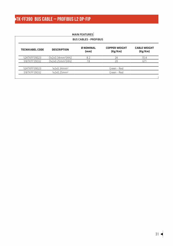
TK-Ff390 BUS CABLE – PROFIBUS L2 DP-FIP
MAIN FEATURES
BUS CABLES - PROFIBUS
TECNIKABEL CODE DESCRIPTIONØ NOMINAL
(mm)COPPER WEIGHT
(Kg/Km)CABLE WEIGHT
(Kg/Km)
524TKFF39023 (1x2x0.34mm²)HH2 8.2 24 70.4518TKFF39032 (1x2x0.25mm²)HH2 7.8 20 67.1
524TKFF39023 1x2x0.34mm² Green - Red518TKFF39032 1x2x0.25mm² Green - Red
31

TKFF390-SERIES CABLES FOR HIGH DYNAMIC APPLICATIONs PUR OIL RESISTANT, UL/CSA APPROVAL, HALOGEN FREETK-Ff390 BUS CABLE – canopen – canbus
CABLE SPECIFICATIONS
ConductorCEI 20-29 Class 6 – IEC 60228 Class 6 – VDE 0295 Class 6
Overall ShieldAluminum/Plastic Tape and Tinned Copper Coverage ≥ 85% according to EMC 89/336 ©
InsulationPolyolefin (UL-CSA Standards)
SheathPolyurethane 11Y (UL-CSA Standards)
Core identificationSee following table
Outer jacket colourViolet Ral 4001 according to DESINA colour chart page 163, other colours available upon request
TECHNICAL DATA
Operating voltage30V (300V on request)
Bending Radius5 x Ø (Static Installation) 7.5 x Ø (Dynamic Installation)
Test voltage1000V a.c. or 2000V a.c.
Maximum Speed300 m/min
Mutual capacitance≤ 60 pF/m
Maximum Acceleration50 m/s²
Characteristic impedance120 Ω ± 15 Ω
Maximum Chain length15 m (horizontal)
Transmission speed1000 Kbit/s with maximum length 40m500 Kbit/s with maximum length 300m100 Kbit/s with maximum length 600m50 Kbit/s with maximum length 1000m
Flex life5.000.000 cycles tested
Temperature range- 40°C ÷ +90°C
TorsionPlease contact our technical support office
Maximum Pulling Force20N/mm² (dynamic use) or 50N/mm² (static use)
European Directives 2011/65/CE (RoHS - Reduction of Hazardous Substances) and 2002/96/CE (WEEE – Waste from Electrical and Electronic Equipment)32

TK-Ff390 BUS CABLE – canopen – canbus
MAIN FEATURES
BUS CABLES – CANOPEN - CANBUS
TECNIKABEL CODE DESCRIPTIONØ NOMINAL
(mm)COPPER WEIGHT
(Kg/Km)CABLE WEIGHT
(Kg/Km)
525TKFF39028 (2x0.34)H2 6 25 50525TKFF39027 (2x2x0.34)H2 7.5 36 68.5525TKFF39029 (1x4x0.34)Q/H2 7.5 36 68.5530TKFF39019 (2x0.50)H2 6.8 28 69.1530TKFF39023 (2x2x0.50)H2 8.8 48 92.7
525TKFF39028 2x0.34 (White – Brown)525TKFF39027 2x2x0.34 (White – Brown) – (Green – Yellow)525TKFF39029 1x4x0.34 White – Green – Brown – Yellow530TKFF39019 2x0.50 (White – Brown)530TKFF39023 2x2x0.50 (White – Brown) – (Green – Yellow)
REFERENCE STANDARDS
Cable according to UL758, UL1581 and CSA C22.2 210.2UL 90°C 30V - Style 20671 – CSA AWM I/II A/B 90°C 30V
Hydrocarbons and Oil ResistanceUL 1581 – VDE 0472 part 803 A/B
Flame RetardantCEI 20-35 – EN50265 – IEC 60332-1 – UL VW-1 – CSA FT1
Water ResistanceUL 1581 – IEC 60811
Halogen FreeCEI 20-37 – IEC 60754-1 – EN 50267-2-1
EC Directives Product compliant with Low Voltage Regulation 72/33/EEC
Directive EMC 2014/30/EU ElectromagneticCompatibility
33

TKFF390-SERIES CABLES FOR HIGH DYNAMIC APPLICATIONs PUR OIL RESISTANT, UL/CSA APPROVAL, HALOGEN FREETK-Ff390 BUS CABLE – devicenet drop and trunk
CABLE SPECIFICATIONS
ConductorCEI 20-29 Class 6 – IEC 60228 Class 6 – VDE 0295 Class 6
Overall ShieldTinned Copper Coverage ≥ 85% according to EMC 89/336 ©
InsulationPolyolefin and Foam Polyolefin (UL-CSA Standards)
SheathPolyurethane 11Y (UL-CSA Standards)
Core identificationSee following table
Outer jacket colourViolet Ral 4001 according to DESINA colour chart page 163, other colours available upon request
Pairs ShieldAluminum/Plastic on each pairs
TECHNICAL DATA
Operating voltage30V (300V on request)
Bending Radius5 x Ø (Static Installation) 7.5 x Ø (Dynamic Installation)
Test voltage1000V a.c. or 2000V a.c.
Maximum Speed300 m/min
Mutual capacitance≤ 50 pF/m
Maximum Acceleration50 m/s²
Characteristic impedance120 Ω ± 15 Ω
Maximum Chain length15 m (horizontal)
Transmission speed500 Kbit/s with maximum length 200m250 Kbit/s with maximum length 250m125 Kbit/s with maximum length 500m
Flex life5.000.000 cycles tested
Temperature range- 40°C ÷ +90°C
TorsionPlease contact our technical support office
Maximum Pulling Force20N/mm² (dynamic use) or 50N/mm² (static use)
European Directives 2011/65/CE (RoHS - Reduction of Hazardous Substances) and 2002/96/CE (WEEE – Waste from Electrical and Electronic Equipment)34

TK-Ff390 BUS CABLE – devicenet drop and trunk
MAIN FEATURES
BUS CABLES - DEVICENET
TECNIKABEL CODE
DESCRIPTIONØ NOMINAL
(mm)
COPPER WEIGHT(Kg/Km)
CABLE WEIGHT(Kg/Km)
518TKFF39033 [(2xAWG24)H + (2xAWG22)H]H2 Drop 7.1 31 74.7538TKFF39014 [(2xAWG18)H + (2xAWG15)H]H2 Trunk 11 102 179
518TKFF390332xAWG24 - Data
2xAWG22 - Power(Blue – White)(Red – Black)
538TKFF390142xAWG18 - Data
2xAWG15 - Power(Blue – White)(Red – Black)
REFERENCE STANDARDS
Cable according to UL758, UL1581 and CSA C22.2 210.2UL 90°C 30V -Style 20671 – CSA AWM I/II A/B 90°C 30V
Hydrocarbons and Oil ResistanceUL 1581 – VDE 0472 part 803 A/B
Flame RetardantCEI 20-35 – EN50265 – IEC 60332-1 – UL VW-1 – CSA FT1
Water ResistanceUL 1581 – IEC 60811
Halogen FreeCEI 20-37 – IEC 60754-1 – EN 50267-2-1
EC Directives Product compliant with Low Voltage Regulation 72/33/EEC
Directive EMC 2014/30/EU ElectromagneticCompatibility
35

TKFF390-SERIES CABLES FOR HIGH DYNAMIC APPLICATIONs PUR OIL RESISTANT, UL/CSA APPROVAL, HALOGEN FREETK-Ff390 BUS CABLE – interbus
CABLE SPECIFICATIONS
ConductorCEI 20-29 Class 6 – IEC 60228 Class 6 – VDE 0295 Class 6
Overall ShieldAluminum/Plastic Tape and/or Tinned Copper Coverage ≥ 85% according to EMC 89/336 ©
InsulationPolyolefin (UL-CSA Standards)
SheathPolyurethane 11Y (UL-CSA Standards)
Core identificationSee following table
Outer jacket colourViolet Ral 4001 according to DESINA colour chart page 163, other colours available upon request
TECHNICAL DATA
Operating voltage30V (300V on request)
Bending Radius5 x Ø (Static Installation)7.5 x Ø (Dynamic Installation)
Test voltage1000V a.c. or 2000V a.c.
Maximum Speed300 m/min
Mutual capacitance≤ 60 pF/m
Maximum Acceleration50 m/s²
Characteristic impedance100 Ω ± 15 Ω
Maximum Chain length15 m (horizontal)
Transmission speed500 Kbit/s with maximum length 400m
Flex life5.000.000 cycles tested
Temperature range- 40°C ÷ +90°C
TorsionPlease contact our technical support office
Maximum Pulling Force20N/mm² (dynamic use) or 50N/mm² (static use)
REFERENCE STANDARDS
Cable according to UL758, UL1581 and CSA C22.2 210.2UL 90°C 30V - Style 20671 – CSA AWM I/II A/B 90°C 30V
Hydrocarbons and Oil ResistanceUL 1581 – VDE 0472 part 803 A/B
Flame RetardantCEI 20-35 – EN50265 – IEC 60332-1 – UL VW-1 – CSA FT1
Water ResistanceUL 1581 – IEC 60811
Halogen FreeCEI 20-37 – IEC 60754-1 – EN 50267-2-1
EC Directives Product compliant with Low Voltage Regulation 72/33/EEC
Directive EMC 2014/30/EU ElectromagneticCompatibility
European Directives 2011/65/CE (RoHS - Reduction of Hazardous Substances) and 2002/96/CE (WEEE – Waste from Electrical and Electronic Equipment)36

TK-Ff390 BUS CABLE – interbus
MAIN FEATURES
BUS CABLES - INTERBUS
TECNIKABEL CODE DESCRIPTIONØ NOMINAL
(mm)COPPER WEIGHT
(Kg/Km)CABLE WEIGHT
(Kg/Km)
522TKFF39031 (3x2x0.22)HH2 7 24 61.7522TKFF39032 (3x2x0.22 + 3G1)HH2 8.4 61 96.6
522TKFF39031 3x2x0.22 (White-Brown) – (Green-Yellow) – (Grey-Pink)
522TKFF390323x2x0.22 (White-Brown) – (Green-Yellow) – (Grey-Pink)
3G1 Blue – Red – Yellow/Green
37

TKFF390-SERIES CABLES FOR HIGH DYNAMIC APPLICATIONs PUR OIL RESISTANT, UL/CSA APPROVAL, HALOGEN FREETK-Ff390 ethernet – profinet/ethercat category 5e
CABLE SPECIFICATIONS
ConductorCEI 20-29 Class 6 – IEC 60228 Class 6 – VDE 0295 Class 6
Overall ShieldAluminum/Plastic Tape and Tinned Copper Coverage ≥ 85% according to EMC 89/336 ©
InsulationPolyolefin (UL-CSA Standards)
SheathPolyurethane 11Y (UL-CSA Standards)
Core identificationSee following table
Outer jacket colourGreen Ral 6018 according to DESINA colour chart page 163, other colours available upon request
Inner sheathOnly Profinet/Ethernet version
TECHNICAL DATA
Operating voltage30V (300V on request)
Bending Radius5 x Ø (Static Installation) 7.5 x Ø (Dynamic Installation)
Test voltage1000V a.c.
Maximum Speed300 m/min
Mutual capacitance≤ 60 pF/m
Maximum Acceleration50 m/s²
Characteristic impedance100 Ω ± 15 Ω
Maximum Chain length15 m (horizontal)
Transmission speed100 Mbit/s with maximum length 100m10 Mbit/s with maximum length 500m
Flex life5.000.000 cycles tested
Temperature range- 40°C ÷ +90°C
TorsionPlease contact our technical support office
Maximum Pulling Force20N/mm² (dynamic use) or 50N/mm² (static use)
European Directives 2011/65/CE (RoHS - Reduction of Hazardous Substances) and 2002/96/CE (WEEE – Waste from Electrical and Electronic Equipment)38

TK-Ff390 ethernet – profinet/ethercat category 5e
MAIN FEATURES
BUS CABLES - ETHERNET CAT 5E
TECNIKABEL CODE
DESCRIPTIONØ NOMINAL
(mm)
COPPER WEIGHT(Kg/Km)
CABLE WEIGHT(Kg/Km)
518TKFF39034 Ethernet Category 5E (2x2xAWG24)HH2 6.3 21 50518TKFF39037 Ethernet Category 5E (4x2xAWG24)HH2 7.2 33 68512TKFF39004 Ethernet Category 5E (4x2xAWG26)HH2 6.4 26 53
524TKFF39006Ethercat/Profinet Category 5E
(4xAWG22)HH26.5 31 65
518TKFF39039Ethercat/Profinet Category 5E
(4xAWG24)HH25.5 22 46
518TKFF39034 2x2xAWG24 (Blue - White/Blue) - (Orange - White/Orange)
518TKFF39037 4x2xAWG24(Blue - White/Blue) - (Orange - White/Orange)
(Green - White/Green) - (Brown - White/Brown)
512TKFF39004 4x2xAWG24(Blue - White/Blue) - (Orange - White/Orange)
(Green - White/Green) - (Brown - White/Brown)524TKFF39006 2xAWG22 White - Yellow - Blue - Orange518TKFF39039 4xAWG24 White - Yellow - Blue - Orange
REFERENCE STANDARDS
Cable according to UL758, UL1581 and CSA C22.2 210.2UL 90°C 30V -Style 20671 – CSA AWM I/II A/B 90°C 30V
Hydrocarbons and Oil ResistanceUL 1581 – VDE 0472 part 803 A/B
Flame RetardantCEI 20-35 – EN50265 – IEC 60332-1 – UL VW-1 – CSA FT1
Water ResistanceUL 1581 – IEC 60811
Halogen FreeCEI 20-37 – IEC 60754-1 – EN 50267-2-1
EC Directives Product compliant with Low Voltage Regulation 72/33/EEC
Directive EMC 2014/30/EU ElectromagneticCompatibility
39

Cables for dynamic Applications on drag chain high performance - UL/CSA recognized 90°C 30V or 300V (600V on request) according to UL758
TK-Ff390 ethernet category 6
CABLE SPECIFICATIONS
ConductorBare Copper according to CEI 20-29 Class 6 – IEC 60228 Class 6 – VDE 0295 Class 6
Overall ShieldAluminum/Plastic Tape and Tinned Copper Braid Coverage ≥ 85% according to EMC 2014/30/EU ©
InsulationPolyolefin (UL-CSA Standards)
SheathPolyurethane 12Y (UL-CSA Standards)
Core identificationSee following table
Outer jacket colourGreen Ral 6018 according to DESINA colour chart page 163, other colours available upon request
TECHNICAL DATA
Operating voltage30V (300V on request)
Maximum Speed300 m/min
Test voltage1000V a.c. or 2000V a.c.
Maximum Acceleration50 m/s²
Characteristic impedance100 Ω
Maximum Chain length15 m (horizontal)
Mutual capacitance< 50 pF/m
Flex life5.000.000 cycles tested
Temperature range- 40°C ÷ +90°C
TorsionPlease contact our technical support office
Bending Radius5 x Ø (Static Installation) 7.5 x Ø (Dynamic Installation)
Maximum Pulling Force20N/mm² (dynamic use) or 50N/mm² (static use)
European Directives 2011/65/CE (RoHS - Reduction of Hazardous Substances) and 2002/96/CE (WEEE – Waste from Electrical and Electronic Equipment)40

REFERENCE STANDARDS
Cable according to UL758, UL1581 and CSA C22.2 210.2UL 90°C 30V -Style 20671 – CSA AWM I/II A/B 90°C 30V
Hydrocarbons and Oil ResistanceUL 1581 – VDE 0472 part 803 A/B
Flame RetardantCEI 20-35 – EN50265 – IEC 60332-1 – UL VW-1 – CSA FT1
Water ResistanceUL 1581 – IEC 60811
Halogen FreeCEI 20-37 – IEC 60754-1 – EN 50267-2-1
EC Directives Product compliant with Low Volt-age Regulation 72/33/EEC
Directive EMC 2014/30/EU ElectromagneticCompatibility
MAIN FEATURES
TK-Ff390 ethernet category 6
BUS CABLES - ETHERNET CAT 6
TECNIKABEL CODE
DESCRIPTIONØ NOMINAL
(mm)
COPPER WEIGHT(Kg/Km)
CABLE WEIGHT(Kg/Km)
518TKFF39041 Ethernet Category 6 (4x2xAWG24)HH2 7.8 34 75512TKFF39011 Ethernet Category 6 (4x2xAWG26)HH2 7.4 27 63
518TKFF39041 4x2xAWG24(Blue - White/Blue) - (Orange - White/Orange)
(Green - White/Green) - (Brown - White/Brown)
512TKFF39011 4x2xAWG26(Blue - White/Blue) - (Orange - White/Orange)
(Green - White/Green) - (Brown - White/Brown)
41

Cables for dynamic Applications on drag chain high performance - UL/CSA recognized 90°C 30V or 300V (600V on request) according to UL758
TK-Ff390 ethernet category 7
CABLE SPECIFICATIONS
ConductorBare Copper according to CEI 20-29 Class 6 – IEC 60228 Class 6 – VDE 0295 Class 6
Overall ShieldAluminum/Plastic Tape and Tinned Copper Braid Coverage ≥ 85% according to EMC 2014/30/EU ©
InsulationPolyolefin (UL-CSA Standards)
SheathPolyurethane 12Y (UL-CSA Standards)
Core identificationSee following table
Outer jacket colourGreen Ral 6018 according to DESINA colour chart page 163, other colours available upon request
Pairs ShieldAluminum/Plastic Tape
TECHNICAL DATA
Operating voltage30V (300V on request)
Maximum Speed300 m/min
Test voltage1000V a.c. or 2000V a.c.
Maximum Acceleration50 m/s²
Characteristic impedance100 Ω
Maximum Chain length15 m (horizontal)
Mutual capacitance< 50 pF/m
Flex life5.000.000 cycles tested
Temperature range- 40°C ÷ +90°C
TorsionPlease contact our technical support office
Bending Radius5 x Ø (Static Installation) 7.5 x Ø (Dynamic Installation)
Maximum Pulling Force20N/mm² (dynamic use) or 50N/mm² (static use)
European Directives 2011/65/CE (RoHS - Reduction of Hazardous Substances) and 2002/96/CE (WEEE – Waste from Electrical and Electronic Equipment)42

MAIN FEATURES
TK-Ff390 ethernet category 7
BUS CABLES - ETHERNET CAT 7
TECNIKABEL CODE
DESCRIPTIONØ NOMINAL
(mm)
COPPER WEIGHT(Kg/Km)
CABLE WEIGHT(Kg/Km)
518TKFF39040 Ethernet Category 7 [4x(2xAWG24)H]HH2 10.3 42 108512TKFF39012 Ethernet Category 7 [4x(2xAWG26)H]HH2 9.4 32 90
518TKFF39040 4x2xAWG24(Blue - White/Blue) - (Orange - White/Orange)
(Green - White/Green) - (Brown - White/Brown)
512TKFF39012 4x2xAWG26(Blue - White/Blue) - (Orange - White/Orange)
(Green - White/Green) - (Brown - White/Brown)
REFERENCE STANDARDS
Cable according to UL758, UL1581 and CSA C22.2 210.2UL 90°C 30V - Style 20671 – CSA AWM I/II A/B 90°C 30V
Hydrocarbons and Oil ResistanceUL 1581 – VDE 0472 part 803 A/B
Flame RetardantCEI 20-35 – EN50265 – IEC 60332-1 – UL VW-1 – CSA FT1
Water ResistanceUL 1581 – IEC 60811
Halogen FreeCEI 20-37 – IEC 60754-1 – EN 50267-2-1
EC Directives Product compliant with Low Voltage Regulation 72/33/EEC
Directive EMC 2014/30/EU ElectromagneticCompatibility
43

NOTE
44

RESEARCH & DEVELOPMENT
RESEARCH & DEVELOPMENT
TECNIKABEL’S laboratoriesTecnikabel‘s work has always focused on research and development.Tecnikabel has followed this policy over the last few years, investing significant sums, as well as human resources, in research and development. Six is many for some, little to others, I suggest leaving it out.
Tecnikabel's laboratories can test product quality in all segments by carrying out the following:
• Electric/electronic tests• Physical/chemical tests• Mechanical/Dynamic tests
RESEARCH & DEVELOPMENT
These images are solely for illustrative purposes 45

ELECTRIC/ELECTRONIC TESTS
Tecnikabel works jointly with customers who are leaders in the telecommunications, broadcasting, and data transmission sector, as well as in the automation, offshore, and railway sectors.
Specific products require particular transmission measurements, such as: resistance, electric capacitance, impedance,
return loss, attenuation, crosstalk, skew time, etc...These measurements provide feedback when preparing designs and are useful for project validation and cable prototyping.
The CPMS transmission parameter test bench has three different sections capable of measuring transmission features
for:• LAN cables to a frequency of 600 Mhz• coaxial cables• paired cables
The bench consists of:• a network analyser up to 3 GHz• an LCR meter• hardware and software for data acquisition and processing
This test bench was validated by TELECOM Italia when approving (telephone) exchange cables (ADSL, coaxial, paired, etc...).The transmission test system is completed with other HP 4194 A and HP 8753 A network analysers spanning a frequency range of a few Hz to 3 Giga Hertz.
DIELECTRIC RESISTANCE TESTA General Radio 1836 megohmmeter and a SATURN ISO megohmmeter are used to test the quality of insulation materials.
DIELECTRIC RIGIDITY TESTThese tests are carried out on small-sized specimens of up to 5 kV in the laboratory using an alternating voltage generator. A high voltage cabin is used for larger specimens up to 20 kV.
CURRENT STABILITY TESTThese tests are carried out using a direct voltage generator up to 10 kV.
CABLE OPERATING VOLTAGE TESTThese tests are carried out in two high-voltage cabins with capacity of up to 20 kV and 30 kV respectively.
HIGH-RESOLUTION ELECTRIC RESISTANCE TESTThese tests are carried out using a nanohmmeter for cables with cross-sectional areas greater than 16 mm2.
TRANSMISSION TEST BENCH46

PHYSICAL/CHEMICAL TESTS
The physical and chemical properties of each of the components of the cable must be tested to guarantee that performance remains unaltered throughout the cable’s entire lifecycle.
Instruments used:• Lloyd LRX dynamometer for tensile strengths of up to 2500 N• Mitutoyo PJ 300 profile projector• UL/CEI compliant aging ovens• Mettler PM300 precision scales, accuracy 1/100• Mettler PM100 hygrometric scales, accuracy 1/1000• Kern ALJ 160-4M analytic scales, accuracy 1/1000• Dynamometer for tensile strengths of up to 300,000N• T.G.A.• Cabinets for flame retardant tests according to CEI 20-35/IEC 60332-1, UL 1581 (UL VW1 CSA FT1), UL CL2 and IEC 60332-3 standards
AGING TESTUL/CEI compliant cables.
FIRE-RETARDANT TESTaccording to CEI IEC EN 60332-3.
MATERIAL AGING OVENS
TGA THERMO GRAVIMETRIC ANALYSIS
47

MECHANICAL/DYNAMIC TESTS
In the industrial automation and robotics sector, guaranteeing unaltered cable performances while machines are operating is essential. Mechanical stress from bending, torsion, or a combination of these, are critical issues for this type of use.
Instruments used for these tests:
CABLE CHAINSCable chains with high dynamic performances, increasingly smaller bending radiuses and higher speeds and acceleration are in growing demand for industrial automatic storage systems and machine tools.Tests spanning from a minimum bending radius of 15 mm to a maximum of 250 mm can be carried out. The chains used for tests are driven by brushless servomotors.
CHAIN 1,2,3Top speed: 200 m/min. Maximum acceleration: 10 m/s2 Bending radius: from 15 to 250 mmMaximum length: 18 m
CHAINS 5-8 WITH A LINEAR MOTORTop speed: 300 m/min Acceleration: 50 m/s2 Bending radius: from 50 to 150 Maximumlength: 6 m.
The chains are connected to a data acquisition system, developed in a LabVIEW®, environment, to acquire electrical
resistance values for conductor and monitor trends with regards to the number of cycles in real time.This system allows users to access a database, where they can retrieve and access data easily. The system is also visible via an Intranet and the Internet.
DATA ACQUISITION SYSTEM WITH UP TO 64 CHANNELS
CHAIN WITH A LENGTH OF 18 m – TOP SPEED 200 m/min – MAXIMUM ACCELERATION 10 m/s²48

ROBOT SIMULATORTecnikabel working in close contact with leading robot manufacturers, has developed mechanical simulators that reproduce all of the axes of a wrist robot to test the technical lifespan of a cable after millions of cycles.
MATERIAL AGING OVENS
TORSION SIMULATORThese devices are designed by Tecnikabel technicians to test several cables at the same time, with the possibility of varying: rotation angles, length on which torsion takes place, bending radiuses, speed and acceleration, the combination of different movements in terms of bending and torsion. Both devices can test cables with different diameters.
TORSION SIMULATOR – ANGULAR SPEED 20 RAD/s² ANGULAR ACCELERATION 30 RAD/s²49

HOT PARTICLE RESISTANCE TESTSThe device below is CEI 20-19/2 and HD 22.2 compliant, which consists in bringing an incandescent filament close to a cable, applying an appropriate amount of force, for a predetermined period of time, and then evaluating the integrity of the cable with a voltage test.
HOT PARTICLE TEST DEVICE
UV RESISTANTSome materials used to mold cable ties and associated fixing devices have declared resistance to UV light. The present standards for cable ties require additional testing for resistance to UV light conducted on the completed product. Although there are different exposure methods that can be used to represent actual sunlight exposure, the xenon-arc light source is increasingly recognized as providing the closest representation. The xenon-arc light source exposure method is found in ISO 4892-2 (method A) which is essentially harmonized with ASTM G 155 (Method 1). The test for cable ties consists of 1000 hours of continuous exposure to this light source, and intermittent exposure to water spray. Following this UV light exposure, cable ties and fixing devices are subjected to mechanical tests to determine any degree of degradation.
UV TEST MACHINE Q-SUN Xe-2 Xenon TEST CHAMBER
50

NOTE
51

TECHNICAL INFORMATIONSAWG CONDUCTOR SIZE ACCORDING TO UL758 STANDARDS
Diameter of the solid conductor Stranded wire cross-sections
Nominal Minimum Nominal Minimum
Size
Conductors
AWG
Mils mm. Mils mm. Cmils mm2 Cmils mm2
50 0.99 0.0251 0.98 0.025 0.980 0.000497 0.960 0.000486
49 1.11 0.0282 1.10 0.028 1.23 0.000624 1.21 0.000613
48 1.24 0.0315 1.23 0.031 1.54 0.000768 1.51 0.000765
47 1.40 0.0356 1.39 0.035 1.96 0.000993 1.92 0.000973
46 1.57 0.0399 1.55 0.039 2.46 0.00125 2.41 0.00122
45 1.76 0.0447 1.74 0.044 3.10 0.00157 3.04 0.00154
44 2.0 0.051 1.98 0.050 4.0 0.00203 3.92 0.00198
43 2.2 0.056 2.18 0.055 4.84 0.00245 4.74 0.00240
42 2.5 0.064 2.48 0.063 6.25 0.00317 6.13 0.003115
41 2.8 0.071 2.77 0.070 7.84 0.00397 7.68 0.00389
40 3.1 0.079 3.07 0.078 9.61 0.00487 9.42 0.00477
39 3.5 0.089 3.47 0.088 12.2 0.00621 11.9 0.00603
38 4.0 0.0102 3.96 0.101 16.0 0.00811 15.7 0.00796
37 4.5 0.114 4.46 0.113 20.2 0.0103 19.8 0.0100
36 5.0 0.127 4.95 0.126 25.0 0.0127 24.5 0.0124
35 5.6 0.142 5.54 0.141 31.4 0.0159 30.8 0.0156
34 6.3 0.160 6.24 0.158 39.7 0.020 38.9 0.0197
33 7.1 0.180 7.03 0.179 50.4 0.0255 49.4 0.0250
32 8.0 0.203 7.92 0.201 64.0 0.0324 62.7 0.0318
31 8.9 0.226 8.81 0.224 79.2 0.0401 77.6 0.0393
30 10.0 0.254 9.9 0.251 100 0.0507 98 0.0497
29 11.3 0.287 11.2 0.284 128 0.0647 125 0.0633
28 12.6 0.320 12.5 0.318 159 0.0804 156 0.0790
27 14.2 0.361 14.1 0.358 202 0.102 198 0.100
26 15.9 0.404 15.7 0.399 253 0.128 248 0.126
25 17.9 0.455 17.7 0.450 320 0.162 314 0.159
24 20.1 0.511 19.9 0.506 404 0.205 396 0.201
23 22.6 0.574 22.4 0.569 511 0.259 501 0.254
22 25.3 0.643 25.0 0.635 640 0.324 627 0.318
21 28.5 0.724 28.2 0.716 812 0.412 796 0.404
20 32.0 0.813 31.7 0.805 1020 0.519 1000 0.509
19 35.9 0.912 35.6 0.904 1290 0.653 1264 0.641
18 40.3 1.02 40.0 1.016 1620 0.823 1588 0.807
17 45.3 1.15 44.9 1.140 2050 1.04 2009 1.02
16 50.8 1.29 50.3 1.278 2580 1.31 2528 1.28
15 57.1 1.45 56.5 1.435 3260 1.65 3195 1.62
14 64.1 1.63 63.5 1.613 4110 2.08 4028 2.04
13 72.0 1.83 71.0 1.80 5180 2.63 5076 2.58
12 80.8 2.05 80.0 2.03 6530 3.31 6399 3.24
52

AWG CONDUCTOR SIZE ACCORDING TO UL758 STANDARDS
Diameter of the solid conductor Stranded wire cross-sections
Nominal Minimum Nominal Minimum
Size
Conductors
AWG
Mils mm. Mils mm. Cmils mm2 Cmils mm2
11 90.7 2.30 90 2.29 8230 4.17 8065 4.09
10 101.9 2.588 101 2.57 10380 5.261 10172 5.16
9 114.4 2.906 113 2.87 13090 6.631 12828 6.50
8 128.5 3.264 127 3.23 16510 8.367 16180 8.2
7 144.3 3.665 143 3.63 20820 10.55 20404 10.34
6 162.0 4.115 160 4.06 26240 13.30 25715 13.03
5 181.9 4.620 180 4.57 33090 16.77 32428 16.43
4 204.3 5.189 202 5.13 41740 21.15 40905 20.73
3 229.3 5.827 227 5.77 52620 26.67 51568 26.14
2 257.6 6.543 255 6.48 66360 33.62 65033 32.95
1 289.3 7.348 286 7.26 83690 42.41 82016 41.56
1/0 324.9 8.252 322 8.18 105600 53.49 103488 52.42
2/0 364.8 9.226 361 9.17 133100 67.43 130438 66.08
3/0 409.6 10.40 406 10.31 167800 85.01 164444 83.31
4/0 460.0 11.68 455 11.56 211600 107.2 207368 105.1
250 - - - - 250 127 245 124.1
300 - - - - 300 152 294 149.0
350 - - - - 350 177 343 173.8
400 - - - - 400 203 392 198.6
450 - - - - 450 228 441 223.5
500 - - - - 500 253 490 248.3
550 - - - - 550 279 539 273.1
600 - - - - 600 304 588 297.9
650 - - - - 650 329 637 322.8
700 - - - - 700 355 686 347.6
750 - - - - 750 380 735 372.4
800 - - - - 800 405 784 397.2
900 - - - - 900 456 882 446.9
1000 - - - - 1000 507 980 496.6
1100 - - - - 1100 557 1078 546.2
1200 - - - - 1200 608 1178 595.9
1250 - - - - 1250 633 1225 620.7
1300 - - - - 1300 659 1274 645.5
1400 - - - - 1400 709 1372 695.2
1500 - - - - 1500 760 1470 744.9
1600 - - - - 1600 811 1568 794.5
1700 - - - - 1700 861 1666 844.2
1750 1750 887 1715 869.0
1800 - - - - 1800 912 1764 893.8
1900 - - - - 1900 963 1862 943.5
2000 - - - - 2000 1010 1960 993.153

GENERAL CHARACTERISTICS OF PLASTIC MATERIALS
Material ReferenceAccording
to VDE
Temperature
Range
°C
Elongation
at break
%
Tensile
strenght
N/mm2
Dielectric
constantDensity
Polyvinyl chloride PVC Y -30 ÷ +105 150 ÷ 300 15 ÷ 25 3.5 ÷ 4.5 1.3 ÷ 1.45
Semi-rigid Polyvinyl
chlorideSR-PVC - -15 ÷ +105 150 ÷ 200 15 ÷ 21 3.5 ÷ 4 1.2 ÷ 1.35
High-Density
PolyethyleneHDPE 2Y -50 ÷ +100 400 ÷ 600 20 ÷ 30 2.3
0.94 ÷
0.95
Low-Density
PolyethyleneLDPE 2Y -50 ÷ +70 400 ÷ 600 10 ÷ 20 2.3 0.91 ÷ 0.92
Cellular Polyethylene PES 02Y -50 ÷ +70 300 ÷ 400 8 ÷ 12 1.6 0.5 ÷ 0.6
Cross-linked
PolyethyleneXLPE 2X -50 ÷ +105 300 ÷ 400 15 ÷ 25 2.3 0.93
Polypropylene PP 9Y -30 ÷ +105 500 ÷ 700 15 ÷ 25 2.25 0.90
Polyester TPE-E 12Y-50 ÷ +105
(+125)
400 ÷
100015 ÷ 25 2.8 ÷ 3.8 1.2 ÷ 1.3
Polyurethane PUR 11Y -50 ÷ +90 300 ÷ 600 30 ÷ 60 4 ÷ 6 1.1 ÷ 1.3
Polyolefin Elastomer TPE-O - -40 ÷ +120 400 ÷ 600 9 ÷ 15 2.7 1.2 ÷ 1.25
LSZH Compuond M1 H -40 ÷ +80 150 ÷ 250 10 ÷ 15 3.5 ÷ 5 1.45 ÷ 1.6
LSZH Cross-linked
CompuondM2 HX -40 ÷ +105 150 ÷ 250 10 ÷ 15 3.5 ÷ 5 1.45 ÷ 1.6
Polyamide PA 4Y -70 ÷ +125 200 ÷ 400 50 ÷ 80 3.5 1.1 ÷ 1.15
Polyethereterketone PEEK - -60 ÷ +200 100 ÷ 150 40 ÷ 50 3.2 1.2
Polyvinylidene Fluoride PVDF 10Y -50 ÷ +130 100 ÷ 300 40 ÷ 50 7 1.7 ÷ 1.8
Ethylenetetrafluoroethylene ETFE 7Y -100 ÷ +170 100 ÷ 300 40 ÷ 50 2.7 1.7
Per fluoro
ethylenepropyleneFEP 6Y -100 ÷ +215 250 ÷ 350 20 ÷ 30 2.15 2.15
Polytetrafluoroethylene PTFE 5Y -180 ÷ +260 250 ÷ 400 20 ÷ 30 2.1 2,2
Perfluoroalkoxyl PFA - -180 ÷ +260 200 ÷ 400 20 ÷ 30 2.1 2.15
Volume
resistivity
kV/mm
Flame
resistance
Water
Resistance
Hydrocarbons
Resistance
Oil and
grease
Resistance
Solventes
Resistance
Acid
Resistance
Wheather
Resistance
15Self
extinguishingVery Good Sufficient Good Insufficient Good Good
20Self
extinguishingVery Good Sufficient Good Insufficient Good Good
24 Inflammable Very Good Insufficient Good Insufficient Good Good
24 Inflammable Very Good Insufficient Good Insufficient Good Good
20 Inflammable Very Good Insufficient Good Insufficient Good Good
24 Inflammable Very Good Good Good Sufficient Good Good
26 Inflammable Very Good Sufficient Very Good Sufficient Good Good
15 Inflammable Good Good Very Good Good Good Good
20
Inflammable
(Self
extinguishing)
Good Good Very Good Good Sufficient Good
24 Inflammable Good Insufficient Insufficient Insufficient Good Good
25Self
extinguishingSufficient Sufficient Insufficient Insufficient Insufficient Good
25Self
extinguishingSufficient Good Sufficient Sufficient Insufficient Good
15 Inflammable Sufficient Sufficient Very Good Good Sufficient Good
20No
InflammableGood Good Very Good Very Good Very Good Good
10Self
extinguishingGood Good Good Very Good Very Good Very Good
19No
InflammableVery Good Very Good Very Good Very Good Very Good Very Good
20No
InflammableVery Good Very Good Very Good Very Good Very Good Very Good
19No
InflammableVery Good Very Good Very Good Very Good Very Good Very Good
20No
InflammableVery Good Very Good Very Good Very Good Very Good Very Good
54

Material ReferenceAccording
to VDE
Temperature
Range
°C
Elongation
at break
%
Tensile
strenght
N/mm2
Dielectric
constantDensity
Polyvinyl chloride PVC Y -30 ÷ +105 150 ÷ 300 15 ÷ 25 3.5 ÷ 4.5 1.3 ÷ 1.45
Semi-rigid Polyvinyl
chlorideSR-PVC - -15 ÷ +105 150 ÷ 200 15 ÷ 21 3.5 ÷ 4 1.2 ÷ 1.35
High-Density
PolyethyleneHDPE 2Y -50 ÷ +100 400 ÷ 600 20 ÷ 30 2.3
0.94 ÷
0.95
Low-Density
PolyethyleneLDPE 2Y -50 ÷ +70 400 ÷ 600 10 ÷ 20 2.3 0.91 ÷ 0.92
Cellular Polyethylene PES 02Y -50 ÷ +70 300 ÷ 400 8 ÷ 12 1.6 0.5 ÷ 0.6
Cross-linked
PolyethyleneXLPE 2X -50 ÷ +105 300 ÷ 400 15 ÷ 25 2.3 0.93
Polypropylene PP 9Y -30 ÷ +105 500 ÷ 700 15 ÷ 25 2.25 0.90
Polyester TPE-E 12Y-50 ÷ +105
(+125)
400 ÷
100015 ÷ 25 2.8 ÷ 3.8 1.2 ÷ 1.3
Polyurethane PUR 11Y -50 ÷ +90 300 ÷ 600 30 ÷ 60 4 ÷ 6 1.1 ÷ 1.3
Polyolefin Elastomer TPE-O - -40 ÷ +120 400 ÷ 600 9 ÷ 15 2.7 1.2 ÷ 1.25
LSZH Compuond M1 H -40 ÷ +80 150 ÷ 250 10 ÷ 15 3.5 ÷ 5 1.45 ÷ 1.6
LSZH Cross-linked
CompuondM2 HX -40 ÷ +105 150 ÷ 250 10 ÷ 15 3.5 ÷ 5 1.45 ÷ 1.6
Polyamide PA 4Y -70 ÷ +125 200 ÷ 400 50 ÷ 80 3.5 1.1 ÷ 1.15
Polyethereterketone PEEK - -60 ÷ +200 100 ÷ 150 40 ÷ 50 3.2 1.2
Polyvinylidene Fluoride PVDF 10Y -50 ÷ +130 100 ÷ 300 40 ÷ 50 7 1.7 ÷ 1.8
Ethylenetetrafluoroethylene ETFE 7Y -100 ÷ +170 100 ÷ 300 40 ÷ 50 2.7 1.7
Per fluoro
ethylenepropyleneFEP 6Y -100 ÷ +215 250 ÷ 350 20 ÷ 30 2.15 2.15
Polytetrafluoroethylene PTFE 5Y -180 ÷ +260 250 ÷ 400 20 ÷ 30 2.1 2,2
Perfluoroalkoxyl PFA - -180 ÷ +260 200 ÷ 400 20 ÷ 30 2.1 2.15
GENERAL CHARACTERISTICS OF PLASTIC MATERIALS
Volume
resistivity
kV/mm
Flame
resistance
Water
Resistance
Hydrocarbons
Resistance
Oil and
grease
Resistance
Solventes
Resistance
Acid
Resistance
Wheather
Resistance
15Self
extinguishingVery Good Sufficient Good Insufficient Good Good
20Self
extinguishingVery Good Sufficient Good Insufficient Good Good
24 Inflammable Very Good Insufficient Good Insufficient Good Good
24 Inflammable Very Good Insufficient Good Insufficient Good Good
20 Inflammable Very Good Insufficient Good Insufficient Good Good
24 Inflammable Very Good Good Good Sufficient Good Good
26 Inflammable Very Good Sufficient Very Good Sufficient Good Good
15 Inflammable Good Good Very Good Good Good Good
20
Inflammable
(Self
extinguishing)
Good Good Very Good Good Sufficient Good
24 Inflammable Good Insufficient Insufficient Insufficient Good Good
25Self
extinguishingSufficient Sufficient Insufficient Insufficient Insufficient Good
25Self
extinguishingSufficient Good Sufficient Sufficient Insufficient Good
15 Inflammable Sufficient Sufficient Very Good Good Sufficient Good
20No
InflammableGood Good Very Good Very Good Very Good Good
10Self
extinguishingGood Good Good Very Good Very Good Very Good
19No
InflammableVery Good Very Good Very Good Very Good Very Good Very Good
20No
InflammableVery Good Very Good Very Good Very Good Very Good Very Good
19No
InflammableVery Good Very Good Very Good Very Good Very Good Very Good
20No
InflammableVery Good Very Good Very Good Very Good Very Good Very Good
55

CLASS 1 - SOLID CONDUCTOR FOR SINGLE-CORE AND MULTICORE CABLES
Nominal Section
mm²
Maximum resistance of conductors at 20°C
Circular annealed copper conductors
Plain
Ω/km
Metal-Coated
Ω/km
0,5 36,0 36,7
0,75 24,5 24,8
1,0 18,1 18,2
1,5 12,1 12,2
2,5 7,41 7,56
4 4,61 4,70
6 3,08 3,11
10 1,83 1,84
16 1,15 1,16
25 0,727 -
35 0,524 -
50 0,387 -
70 0,268 -
95 0,193 -
120 0,153 -
150 0,124 -
185 0,101 -
240 0,0775 -
300 0,0620 -
400 0,0465 -
500 - -
630 - -
800 - -
1000 - -
56

CLASS 2 - STRANDED CONDUCTORS FOR SINGLE-CORE AND MULTICORE CABLES
Nominal Section
mm²
Minimum number of wires in the conductorMaximum resistance
of conductors at 20°C
Cicular Compacted ShapedAnnealed copper
conductor
Cu Al Cu Al Cu AlPlain
Ω/km
Metal-
Coated
Ω/km
0,5 7 - - - - - 36,0 36,7
0,75 7 - - - - - 24,5 24,8
1,0 7 - - - - - 18,1 18,2
1,5 7 - 6 - - - 12,1 12,2
2,5 7 - 6 - - - 7,41 7,56
4 7 - 6 - - - 4,61 4,70
6 7 - 6 - - - 3,08 3,11
10 7 7 6 6 - - 1,83 1,84
16 7 7 6 6 - - 1,15 1,16
25 7 7 6 6 6 6 0,727 0,734
35 7 7 6 6 6 6 0,524 0,529
50 19 19 6 6 6 6 0,387 0,391
70 19 19 12 12 12 12 0,268 0,270
95 19 19 15 15 15 15 0,193 0,195
120 37 37 18 18 18 18 0,153 0,154
150 37 37 18 18 18 18 0,124 0,126
185 37 37 30 30 30 30 0,0991 0,100
240 37 37 34 34 34 34 0,0754 0,0762
300 61 61 34 34 34 34 0,0601 0,0607
400 61 61 53 53 53 53 0,047 0,0475
500 61 61 53 53 53 53 0,0366 0,0369
630 91 91 53 53 53 53 0,0283 0,0286
800 91 91 53 53 - - 0,0221 0,0224
1000 91 91 53 53 - - 0,0177 0,0291
57

CLASS 5 - FLEXIBLE COPPER CONDUCTORS FOR SINGLE-CORE AND MULTICORE CABLES
Nominal Section
mm²
Maximum diameter of wire in
conductor
mm
Maximum resistance of conductors at 20°C
Circular annealed copper conductors
Plain
Ω/km
Metal-Coated
Ω/km
0,5 0,21 39,0 40,1
0,75 0,21 26,0 26,7
1,0 0,21 19,5 20,0
1,5 0,26 13,3 13,7
2,5 0,26 7,98 8,21
4 0,31 4,95 5,09
6 0,31 3,30 3,39
10 0,41 1,91 1,95
16 0,41 1,21 1,24
25 0,41 0,780 0,795
35 0,41 0,554 0,565
50 0,41 0,386 0,393
70 0,51 0,272 0,277
95 0,51 0,206 0,210
120 0,51 0,161 0,164
150 0,51 0,129 0,132
185 0,51 0,106 0,108
240 0,51 0,0801 0,0817
300 0,51 0,0641 0,0654
400 0,51 0,0486 0,0495
500 0,61 0,0384 0,0391
630 0,61 0,0287 0,0292
58

CLASS 6 - FLEXIBLE COPPER CONDUCTORS FOR SINGLE-CORE AND MULTICORE CABLES
Nominal Section
mm²
Maximum diameter of wire in
conductor
mm
Maximum resistance of conductors at 20°C
Circular annealed copper conductors
Plain
Ω/km
Metal-Coated
Ω/km
0,5 0,16 39,0 40,1
0,75 0,16 26,0 26,7
1,0 0,16 19,5 20,0
1,5 0,16 13,3 13,7
2,5 0,16 7,98 8,21
4 0,16 4,95 5,09
6 0,21 3,30 3,39
10 0,21 1,91 1,95
16 0,21 1,21 1,24
25 0,21 0,780 0,795
35 0,21 0,554 0,565
50 0,31 0,386 0,393
70 0,31 0,272 0,277
95 0,31 0,206 0,210
120 0,31 0,161 0,164
150 0,31 0,129 0,132
185 0,41 0,106 0,108
240 0,41 0,0801 0,0817
300 0,41 0,0641 0,0654
59

LOW CAPACITANCE POWER CABLES
With the use of the latest generation in IGBT (power semiconductors used in INVERTERS) electrical phenomena that was once almost insignificant can be enhanced, such as:
a) Attenuation of energy being transmitted to the motor from the inverterb) Leakage current to ground
Especially when this is a consequence of increasingly faster switching fronts* (approximately 8 kV/μsec).
PHENOMENON (A)The influence of cable capacitance (C) on power transmission is fundamental,since line attenuationis a=√wRC. Therefore, the lower the electric capacitance of the cable (conductor/conductor and conductor/shield) the greater the power transmitted to the motor from the inverter/converter, therefore enhancing system performance.
PHENOMENON (B)The cable is considered a capacitor, because the capacitance (C) generated between two conductors and between a conductor and shield increases with the length of the cable itself.The current absorbed by a capacitor and discharged to the ground is I=wCU. As such, we can deduce that, in this case as well, capacitance must also be as low as possible in order to reduce current leakage, which could be responsible for ill- timed differentialinterventions.
EXCEPT FROM NORM IEC 60204-1
CURRENT-CARRYING CAPACITY AND OVERCURRENT PROTECTION OF CONDUCTORS AND CABLES IN THE ELECTRICAL EQUIPMENT OF MACHINES
The purpose of this Annex is to provide additional information on the selection of conductor sizes where the conditions
given for Table 6 (see Clause 12) have to be modified (see notes to Table 6).
D.1 - GENERAL OPERATING CONDITIONS
D.1.1 - Ambient air temperature
The current carrying capacity for PVC insulated conductors given in Table 6 is related to an ambient air temperature of +40
°C. For other ambient air temperatures, the correction factors are given in Table D.1.The correction factors for rubber insulated cables are given by the manufacturer.
Note: The correction factors are derived from lEG 60364-5-52The maximum temperature under normal conditions for PVC 70 DC
Ambient air temperature °C Correction Factor
30 1.15
35 1.08
40 1.00
45 0.91
50 0.82
55 0.71
60 0.58
CORRECTION FACTORS - Tab. D.1
60

D.1.2 - Methods of installation
In machines, the methods of conductor and cable installation between enclosures and individual items of the equipment
shown in Figure D.1 are assumed to be typical (the letters used are in accordance with IEC 60364-5-52: 2001):
• Method B1: using conduits (3.7) and cable trunking systems (3.5) for holding and protecting conductors or single core
cables;
• Method B2: same as B1 but used for multicore cables;
• Method C: multicore cables installed in free air, horizontal or vertical without gap between cables on walls;
• Method E: multicore cables in free air, horizontal or vertical laid on open cable trays (3.4)
B1
B2
C E
Conductors/single core cables in conduit and cable trunking systems
Cables in conduit and cable trunking systems
Cables on walls Cables on open cable trays
Figure D.1 - Methods of conductor and cable installation independent of number of conductors/cables
61

EXAMPLE OF CURRENT-CARRYING CAPACITY ( IZ) OF PVC INSULATED COPPER CONDUCTORS OR CABLES UNDERSTEADY-STATE CONDITIONS IN AN AMBIENT AIR TEMPERATURE OF +40°C FOR DIFFERENT METHODS OF INSTALLATION
Cross Section Area
(mm²)
Current-carrying capacity Iz for three phase circuit
Installation Method (see Figure D.1.2, pag 123)
B1 B2 C E
0.75 8.6 8.5 9.8 10.4
1.0 10.3 10.1 11.7 12.4
1.5 13.5 13.1 15.2 16.1
2.5 18.3 17.4 21 22
4 24 23 28 30
6 31 30 36 37
10 44 40 50 52
16 59 54 66 70
25 77 70 84 88
35 96 86 104 110
50 117 103 125 133
70 149 130 160 171
95 180 156 194 207
120 208 179 225 240
Electronics (pairs)
0.20Not
applicable4.3 4.4 4.4
0.5Not
applicable7.5 7.5 7.8
0.75Not
applicable9.0 9.5 10
Note 1The values of the current-carrying capacity of Table 6 are based on:• One symmetrical three-phase circuit for cross-sectional areas 0,75mm2 and greater• One control circuit pair for cross-sectional areas between 0,2mm2 and 0,75mm2
Note 2For ambient temperature other than 40°C, correct the current-carrying capacities by using values given in Table D.1
Note 3These values are not applicable to flexible cables wound on drums
Note 4For the current-carrying capacities of other cables, see IEC 60364-5-52
62

The wiring has to be resistant against cooling lubrificants used in industrial applications.
63

CABLE IDENTIFICATION TO DIN 47100
Number Color NUmber Color
1 white 31 green-blue
2 brown 32 yellow-blue
3 green 33 green-red
4 yellow 34 yellow-red
5 grey 35 green-black
6 pink 36 yellow-black
7 blue 37 grey-blue
8 red 38 pink-blue
9 black 39 grey-red
10 violet 40 pink-red
11 grey-pink 41 grey-black
12 red-blue 42 pink-black
13 white-green 43 blue-black
14 brown-green 44 red-black
15 white-yellow 45 white-brown-black
16 yellow-brown 46 yellow-green-black
17 white-grey 47 grey-pink-black
18 grey-brown 48 red-blue-black
19 white-pink 49 white-green-black
20 pink-brown 50 green-brown-black
21 white-blue 51 white-yellow-black
22 brown-blue 52 yellow-brown-black
23 white-red 53 white-grey-black
24 brown-red 54 grey-brown-black
25 white-black 55 white-pink-black
26 brown-black 56 pink-brown-black
27 grey-green 57 white-blue-black
28 yellow-grey 58 brown-blue-black
29 pink-green 59 white-red-black
30 yellow-pink 60 brown-red-black
61 black-white
64

instructions
GUIDELINES FOR CABLE I
NSTALLATION
TECNIKABEL’S laboratoriesTecnikabel's work has always focused on research and development.Tecnikabel has followed this policy over the last few years, investing significant sums, as well as human resources, inresearch and development.Six staff members with technical diplomas and degrees work in this division. They are supported by a secretary’s office, which handles customer contacts as well as contacts with other corporate bodies.
Tecnikabel's laboratories can test product quality in all segments by carrying out the following:
• Electric/electronic tests• Physical/chemical tests• Mechanical/Dynamic tests
INSTRUCTIONS
65

GUIDELINES FOR CHOOSING THE RIGHT SHIELD IN YOUR CABLE
Technological innovations have brought electronics applied to automation to high levels of complexity and sophistication.However, this has also made the the automated industry system subject to interference, both in the power supply network and in the area surrounding the plant. These types of interference are referred to as EMI (Electro Magnetic Interference), an acronym which includes coupling phenomena: electric and magnetic field (noise), electrostatic discharge (ESD), conducted disturbance on the network, emission radiated from cables and electronic devices, sensitivity to electromagnetic fields and radio frequencyinterferences (RFI), etc...This causes the automated plant to malfunction, so much as to make it dangerous for workers and objects. In order to guarantee safety, the European Community has issued Directive EMC 89/336, which has been incorporated into Machinery Directive 89/392.A highly important element to reduce EMI is shielding on the device. In our case, it entails choosing the right type of shield, which will be used on the cables.
SHIELD TYPES
1. Aluminium/polyester tape shield wrapped around conductors, pairs, or groups*:
• It offers 100% coverage and requires an uninsulated conductor touching the aluminium in order to guarantee continuity and enhance grounding for electro-static charges
• Very effective against ESD it offers good shielding at low frequencies• Unsuitable for moving cables• Low cost
2. Spiral shield wrapped around either a single or several conductors made of parallel strands:
• Has a maximum coverage of approximately 97%• Suitable for low frequency applications and as protection against ESD• Excellent for bending cables and continued bending-torsion
In order to guarantee signal cable immunity, it has added a conductive tape to the serve shield which enhances its shielding performance, even at high frequencies.
3. Braid shield:
• Has a maximum coverage of approximately 98%• Offers excellent mechanical resistance to repeated bending while maintaining good flexibility• Excellent shielding protection both at low and very high frequencies
4. Braid shields with aluminium tape provide the most complete shield:
• Effective both at low and high frequencies• Excellent protection against ESD• Unsuitable for continuous bending torsion
CHOOSING A SHIELDThe criteria to keep in mind in order to make the best choice are a compromise between the right technical solution and the price. They are:
1. Identifying interferences: ESD, radiated interferences, electromagnetic fields, etc...2. Defining the frequencies for the interferences found in environment and the network3. Precise knowledge of the movements the cable will be subjected to: bending radiuses, speed, acceleration, torsion angles, etc.
Tecnikabel recommends and guides its Customers, ensuring that they choose the best shield for the application provided.a) Tape shield cables:
• For interferences generated by TV signals, crosstalk, radio signals, fluorescent lamps, etc...• Environments with a low EMI level• The presence of ESD generated by synthetic materials (yarns, textiles, etc...)
66

b) Spiral shield cables:
• Low frequency interferences• Where elevated duration in terms of bending and continued torsions is required
c) Braided shield cables:
• For low impedance interferences such as to power inverter motors or to intermittently power inductive loads, etc...• Both high and low frequency interferences, such as from computer cables, cables for instruments and commands
d) Braided and tape shield cables:• Multiple interferences at low and high frequencies for environments with strong electromagnetic fields elevated
background, noise, etc...• Suitable for use with bending and slight torsion for which the aluminium tape is replaced with conductive tape.
Cost comparison for coaxial cablesCosts depend on the shield type as a component of the total cable cost.This structure could change according to the cable project.The ESD shielding efficacy test was made with a 15000V discharge to the ground on a length of 91cm sample.The lower voltage improves the shielding efficiency
EMI SHIELDING EFFICIENCY
ESD SHIELDING EFFICIENCY
Aluminium tapeCopper braidCopper spiralAluminium tape + copper braid
Aluminium tapeCopper braidCopper spiralAluminium tape + copper braid
Aluminium tapeCopper braidCopper spiralAluminium tape + copper braid
COMPARISON BETWEEN SHIELDS
67

NOTE
68

www.tecnikabel.com
PRODUCTION
TK CHINA Cables & ConnectorsFactory Premises Co., Ltd No. 7111 North Dongting RoadTaicang Economy Development AreaTaicang City, Jiangsu Province, ChinaTel. +8617751210891
DISTRIBUTION
TECNIKABEL ME JLT3008 Mazaya Business AvenueJumeirah Lake TowersDubai, UAETel. +9714 4230877
MIDDLE EAST
TECNIKABEL ASIA PTE LTD11 Tuas CresSINGAPORE 638705Tel. +65 6909 3710
ASIA-PACIFIC
HEADQUARTERVOLPIANOVia Brandizzo, 24310088 Volpiano (Turin) ItalyTel. +39 011 9951997Fax +39 011 9953062www.tecnikabel.com
PRODUCTION PLANTSVOLPIANOVia Brandizzo, 24310088 Volpiano (Turin) Italy
ALMESEVia Rivera, 10010040 Almese (Turin) Italy
USA
TECNIKABEL ROMEVia Casali delle Cornacchiole, 15400178 Roma ItalyTel. +39 06 5099 2552 Fax +39 06 5051 4022
ROME
DEUTSCHLANDTK DEUTSCHLAND GmbHHerdewerg 883623 Steingau, GERMANYTel. +49 9421 9744222
BRANCH OFFICES
TECNIKABEL USA638 Spartanburg Hwy Suite 70 #325Hendersonville NC 28792Tel. +1 (828) 845-4180