ROMAC Newsletter - University of Virginia · ROMAC Newsletter To ROMAC Industrial Members, News on...
10
This year has been a particularly exciting year for ROMAC. I am pleased to welcome two new re- search staff members, Dr. Roger Fittro and Dr. Ya Zhang. Roger joined ROMAC in August as a Senior Scientist. Prior to joining ROMAC, Roger was at GE’s Global Research Center, where he led a controls group in the development of new product tech- nologies for applications such as Gas Turbines for Power Genera- tion, High-Speed Compressors, Wind Turbines, Commercial & Military Jet Engines and Diesel- Electric Locomotives. During his 10 years at GE, Roger was also one of the key technology devel- opers and lead project engineer for GE’s Joint Strike Fighter (JSF) advanced engine control program, and he led the technol- ogy development effort for a new high-speed magnetic bearing supported integrated gas com- pressor. Ya is a Visiting Profes- sor from the Beijing University of Chemical Technology. Ya will be working in ROMAC until August 2014. We also have some exciting de- velopments with our software: - RotorSol v3.3 was released in October, 2013. RotorSol v3.4 will be released before the start of 2014. - RotorLab+ v3.0 will be avail- able in December, 2013. - GearRotor v1.0, a code for analyzing geared-systems, will also be available in December, 2013, along with a user manual. There are several new compa- nies that have joined ROMAC in 2013. Our new members are: Daikin Applied Florida Turbine Technology General Atomics OKBM 2013 Annual Meeting Summary The 2013 Annual Meeting, held in Virginia Beach, was very in- formative for all. The Question- naire, which was filled out by both those attending and several ROMAC participants who could not attend, gave us insights into future directions, shortcomings, and strengths. The results of the Questionnaire are listed in the table on the next page. The summary of the Questionnaire responses is on the ROMAC website, on a tab in the page for the 2013 Annual Meeting. We have also posted pictures from the Annual Meeting there. As a result of the comments on the questionnaires, we are expand- ing our faculty and expert input for students and companies. We ROTATING MACHINERY & CONTROLS LABORATORY ROMAC Newsletter To ROMAC Industrial Members, News on Software Releases: RotorSol v3.3 was released in October 2013. RotorSol v3.4 will be released before the start of 2014 RotorLab+ v3.0 will be avail- able in December 2013. GearRotor v1.0, a code for analyzing geared-systems will also be available by December 2013 along with a user manual. Fall 2013 Issue are working on developing the fluid film bearing test rig, to determine the best way to implement it. Software is being updated, and newly available software with much greater capabilities is now available to students to use for their studies and to help members solve rotor dynamics problems. With the exception of the presentations, one of the high- lights of the gathering was the dinner on Tuesday night, held on the top floor of the Cavalier Hotel, which started off with a dark cloud ap- proaching from the Ocean
Transcript of ROMAC Newsletter - University of Virginia · ROMAC Newsletter To ROMAC Industrial Members, News on...
This year has been a particularly
exciting year for ROMAC. I am
pleased to welcome two new re-
search staff members, Dr. Roger
Fittro and Dr. Ya Zhang. Roger
joined ROMAC in August as a
Senior Scientist. Prior to joining
ROMAC, Roger was at GE’s
Global Research Center, where
he led a controls group in the
development of new product tech-
nologies for applications such as
Gas Turbines for Power Genera-
tion, High-Speed Compressors,
Wind Turbines, Commercial &
Military Jet Engines and Diesel-
Electric Locomotives. During his
10 years at GE, Roger was also
one of the key technology devel-
opers and lead project engineer
for GE’s Joint Strike Fighter
(JSF) advanced engine control
program, and he led the technol-
ogy development effort for a new
high-speed magnetic bearing
supported integrated gas com-
pressor. Ya is a Visiting Profes-
sor from the Beijing University of
Chemical Technology. Ya will be
working in ROMAC until August
2014.
We also have some exciting de-
velopments with our software:
- RotorSol v3.3 was released
in October, 2013. RotorSol v3.4
will be released before the start
of 2014.
- RotorLab+ v3.0 will be avail-
able in December, 2013.
- GearRotor v1.0, a code for
analyzing geared-systems, will
also be available in December,
2013, along with a user manual.
There are several new compa-
nies that have joined ROMAC in
2013. Our new members are:
Daikin Applied
Florida Turbine Technology
General Atomics
OKBM
2013 Annual Meeting
Summary
The 2013 Annual Meeting, held
in Virginia Beach, was very in-
formative for all. The Question-
naire, which was filled out by
both those attending and several
ROMAC participants who could
not attend, gave us insights into
future directions, shortcomings,
and strengths. The results of
the Questionnaire are listed in
the table on the next page. The
summary of the Questionnaire
responses is on the ROMAC
website, on a tab in the page for
the 2013 Annual Meeting. We
have also posted pictures from
the Annual Meeting there. As a
result of the comments on the
questionnaires, we are expand-
ing our faculty and expert input
for students and companies. We
ROTATING MACHINERY & CONTROLS LABORATORY
ROMAC Newsletter
To ROMAC Industrial Members,
News on Software Releases:
RotorSol v3.3 was released in
October 2013. RotorSol v3.4
will be released before the start
of 2014
RotorLab+ v3.0 will be avail-
able in December 2013.
GearRotor v1.0, a code for
analyzing geared-systems will
also be available by December
2013 along with a user manual.
Fall 2013 Issue
are working on developing the
fluid film bearing test rig, to
determine the best way to
implement it. Software is
being updated, and newly
available software with much
greater capabilities is now
available to students to use
for their studies and to help
members solve rotor dynamics
problems.
With the exception of the
presentations, one of the high-
lights of the gathering was
the dinner on Tuesday night,
held on the top floor of the
Cavalier Hotel, which started
off with a dark cloud ap-
proaching from the Ocean
side of the dining room, and turned
into a lightning display (with a bit
of thunder) and ended with a won-
derful rainbow to the south of the
room. There is a picture of the
rainbow on the web site. This, in
addition to great food, and good
company, made for an enjoyable
night.
We feel that the Annual Meeting is
an effective way for members and
UVA faculty and students to net-
work and to share problems and
information. We enjoy being able
to host members and to let every-
one know about our research suc-
cesses over the preceding year and
to hear your comments.
In 2014, the Annual Meeting will
be held in Charlottesville, from
June 23 to 27. We will again start
with a reception on Monday night,
but may do lab tours and individ-
ual work with software on Friday
instead of Wednesday afternoon.
Please let us know your sugges-
tions for the meeting. This may
seem early to be making arrange-
ments, but we have to make hotel
commitments soon, and your input
is valued. Would you like us to put
together a short course the week
after the meeting? If so, what
would you like it to cover? Would a
short course Monday, before the
start of the meeting, be a better
day for you and your colleagues?
Results of the Questionnaire
Rotating machinery & Controls Laboratory Page 2
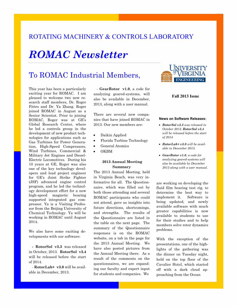
Houston Wood
Professor, Mechanical & Aerospace Eng.
Director of ROMAC
Director of Applied Mathematics
Category Points Percentage
Fluid Film & Rolling Element Bearings 98 39.2%
Rotor Dynamics 65 26.0%
Seals 46 18.4%
Magnetic Bearings & Automatic Controls 21 8.4%
Optimization of Rotor-Bearing Systems 21 8.4%
Turbomachinery Flows 6 2.4%
Other 3 1.2%
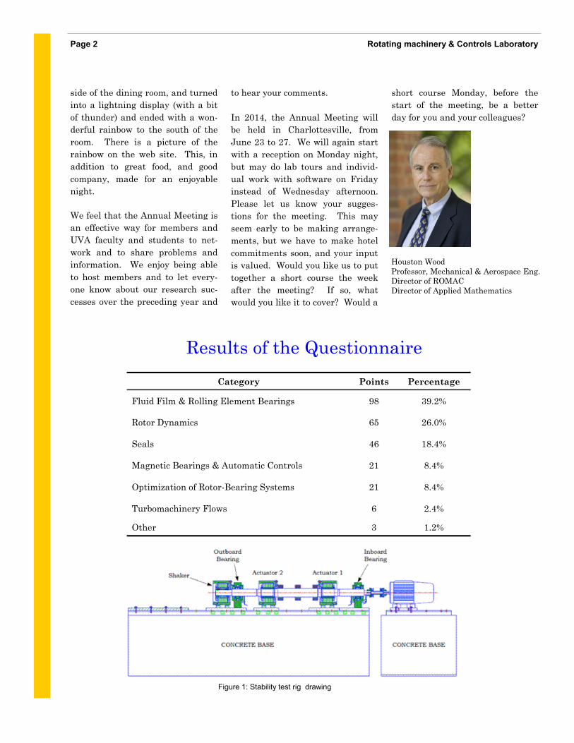
Figure 1: Stability test rig drawing
addition to estimating system
damping, pad temperatures, oil
supply and discharge pressure, and
flow rates, relative power loss will
also be recorded.
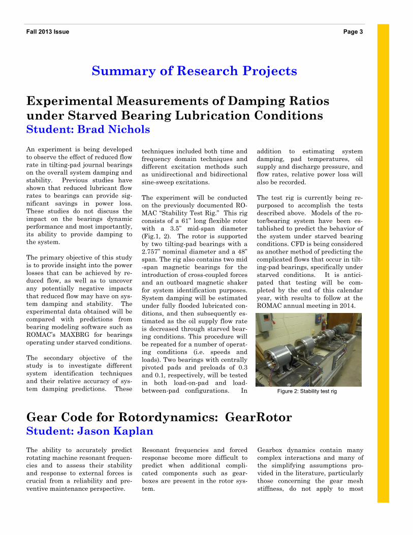
The test rig is currently being re-
purposed to accomplish the tests
described above. Models of the ro-
tor/bearing system have been es-
tablished to predict the behavior of
the system under starved bearing
conditions. CFD is being considered
as another method of predicting the
complicated flows that occur in tilt-
ing-pad bearings, specifically under
starved conditions. It is antici-
pated that testing will be com-
pleted by the end of this calendar
year, with results to follow at the
ROMAC annual meeting in 2014.
An experiment is being developed
to observe the effect of reduced flow
rate in tilting-pad journal bearings
on the overall system damping and
stability. Previous studies have
shown that reduced lubricant flow
rates to bearings can provide sig-
nificant savings in power loss.
These studies do not discuss the
impact on the bearings dynamic
performance and most importantly,
its ability to provide damping to
the system.
The primary objective of this study
is to provide insight into the power
losses that can be achieved by re-
duced flow, as well as to uncover
any potentially negative impacts
that reduced flow may have on sys-
tem damping and stability. The
experimental data obtained will be
compared with predictions from
bearing modeling software such as
ROMAC’s MAXBRG for bearings
operating under starved conditions.
The secondary objective of the
study is to investigate different
system identification techniques
and their relative accuracy of sys-
tem damping predictions. These
techniques included both time and
frequency domain techniques and
different excitation methods such
as unidirectional and bidirectional
sine-sweep excitations.
The experiment will be conducted
on the previously documented RO-
MAC “Stability Test Rig.” This rig
consists of a 61” long flexible rotor
with a 3.5” mid-span diameter
(Fig.1, 2). The rotor is supported
by two tilting-pad bearings with a
2.757” nominal diameter and a 48”
span. The rig also contains two mid
-span magnetic bearings for the
introduction of cross-coupled forces
and an outboard magnetic shaker
for system identification purposes.
System damping will be estimated
under fully flooded lubricated con-
ditions, and then subsequently es-
timated as the oil supply flow rate
is decreased through starved bear-
ing conditions. This procedure will
be repeated for a number of operat-
ing conditions (i.e. speeds and
loads). Two bearings with centrally
pivoted pads and preloads of 0.3
and 0.1, respectively, will be tested
in both load-on-pad and load-
between-pad configurations. In
Experimental Measurements of Damping Ratios
under Starved Bearing Lubrication Conditions Student: Brad Nichols
Page 3 Fall 2013 Issue
Summary of Research Projects
Figure 2: Stability test rig
Gear Code for Rotordynamics: GearRotor Student: Jason Kaplan
The ability to accurately predict
rotating machine resonant frequen-
cies and to assess their stability
and response to external forces is
crucial from a reliability and pre-
ventive maintenance perspective.
Resonant frequencies and forced
response become more difficult to
predict when additional compli-
cated components such as gear-
boxes are present in the rotor sys-
tem.
Gearbox dynamics contain many
complex interactions and many of
the simplifying assumptions pro-
vided in the literature, particularly
those concerning the gear mesh
stiffness, do not apply to most
Rotating machinery & Controls Laboratory Page 4
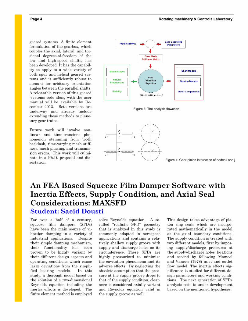
geared systems. A finite element
formulation of the gearbox, which
couples the axial, lateral, and tor-
sional degrees-of-freedom of the
low and high-speed shafts, has
been developed. It has the capabil-
ity to apply to a wide variety of
both spur and helical geared sys-
tems and is sufficiently robust to
account for arbitrary orientation
angles between the parallel shafts.
A releasable version of this geared
-systems code along with the user
manual will be available by De-
cember 2013. Beta versions are
underway and already include
extending these methods to plane-
tary gear trains.
Future work will involve non-
linear and time-transient phe-
nomenon stemming from tooth
backlash, time-varying mesh stiff-
ness, mesh phasing, and transmis-
sion errors. This work will culmi-
nate in a Ph.D. proposal and dis-
sertation. Figure 4: Gear-pinion interaction of nodes i and j
Figure 3: The analysis flowchart
For over a half of a century,
squeeze film dampers (SFDs)
have been the main source of vi-
bration damping in a variety of
industrial applications. Despite
their simple damping mechanism,
their functionality has been
proven to be highly variant by
their different design aspects and
operating conditions which cause
large deviations from the simpli-
fied bearing models. In this
study, a thorough model based on
the solution of a two-dimensional
Reynolds equation including the
inertia effects is developed. The
finite element method is employed
An FEA Based Squeeze Film Damper Software with
Inertia Effects, Supply Condition, and Axial Seal
Considerations: MAXSFD Student: Saeid Dousti
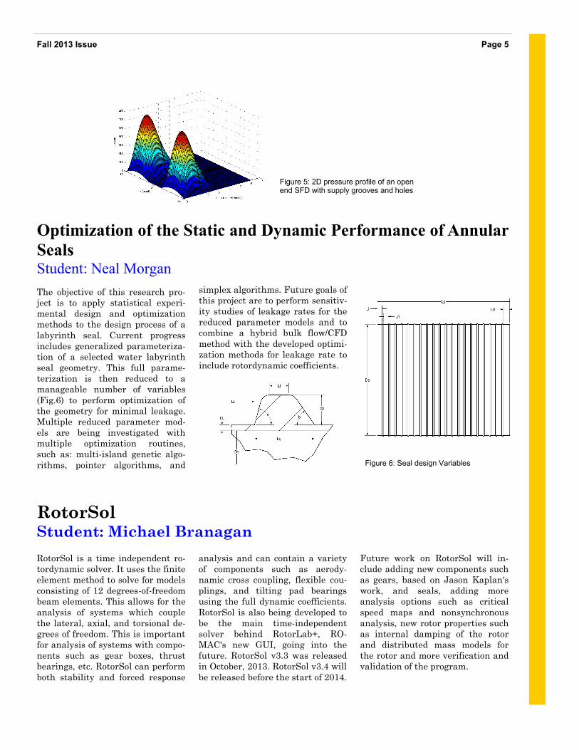
solve Reynolds equation. A so-
called “realistic SFD” geometry
that is analyzed in this study is
commonly adopted in aerospace
applications and contains a rela-
tively shallow supply groove with
supply and discharge holes on its
circumference. These SFDs are
highly pressurized to minimize
the cavitation phenomena and its
adverse effects. By neglecting the
obsolete assumption that the pres-
sure at the supply groove drops to
that of the supply condition, clear-
ance is considered axially variant
and Reynolds equation valid in
the supply groove as well.
This design takes advantage of pis-
ton ring seals which are incorpo-
rated mathematically in the model
as the axial boundary conditions.
The supply condition is treated with
two different models, first by impos-
ing supply/discharge pressures at
the supply/discharge holes’ locations
and second by following Mamool
and Vance’s (1978) inlet and outlet
flow model. The inertia effects sig-
nificance is studied for different de-
sign parameters and working condi-
tions. The next generation of SFDs
analysis code is under development
based on the mentioned hypotheses.
Future work on RotorSol will in-
clude adding new components such
as gears, based on Jason Kaplan's
work, and seals, adding more
analysis options such as critical
speed maps and nonsynchronous
analysis, new rotor properties such
as internal damping of the rotor
and distributed mass models for
the rotor and more verification and
validation of the program.
RotorSol is a time independent ro-
tordynamic solver. It uses the finite
element method to solve for models
consisting of 12 degrees-of-freedom
beam elements. This allows for the
analysis of systems which couple
the lateral, axial, and torsional de-
grees of freedom. This is important
for analysis of systems with compo-
nents such as gear boxes, thrust
bearings, etc. RotorSol can perform
both stability and forced response
analysis and can contain a variety
of components such as aerody-
namic cross coupling, flexible cou-
plings, and tilting pad bearings
using the full dynamic coefficients.
RotorSol is also being developed to
be the main time-independent
solver behind RotorLab+, RO-
MAC's new GUI, going into the
future. RotorSol v3.3 was released
in October, 2013. RotorSol v3.4 will
be released before the start of 2014.
The objective of this research pro-
ject is to apply statistical experi-
mental design and optimization
methods to the design process of a
labyrinth seal. Current progress
includes generalized parameteriza-
tion of a selected water labyrinth
seal geometry. This full parame-
terization is then reduced to a
manageable number of variables
(Fig.6) to perform optimization of
the geometry for minimal leakage.
Multiple reduced parameter mod-
els are being investigated with
multiple optimization routines,
such as: multi-island genetic algo-
rithms, pointer algorithms, and
simplex algorithms. Future goals of
this project are to perform sensitiv-
ity studies of leakage rates for the
reduced parameter models and to
combine a hybrid bulk flow/CFD
method with the developed optimi-
zation methods for leakage rate to
include rotordynamic coefficients.
RotorSol Student: Michael Branagan
Page 5 Fall 2013 Issue
Figure 5: 2D pressure profile of an open end SFD with supply grooves and holes
Optimization of the Static and Dynamic Performance of Annular
Seals Student: Neal Morgan
Figure 6: Seal design Variables
Rotating machinery & Controls Laboratory Page 6
Gas-Expanded Lubricants for Increased Energy Efficiency in
Rotating Machinery Student: Brian Weaver
Lubricants are necessary in rotat-
ing machinery to provide separa-
tion between solid surfaces and to
enable efficient, long-term machine
operation. However, they can also
contribute to power losses and heat
buildup as the fluid is subject to
shear forces. Here, tunable binary
mixtures called gas-expanded lu-
bricants (GELs) are proposed to
overcome these limitations of con-
ventional lubricants. GELs consist
of a synthetic lubricant and carbon
dioxide under pressure with prop-
erties, such as viscosity, that can
be controlled dynamically in re-
sponse to changing environmental
or rotordynamic conditions. By con-
trolling the pressure of the mix-
ture, the bulk mechanical and ther-
mal properties of the fluid can be
specified in real time. These tun-
able fluids will enable operators to
minimize the efficiency losses that
can affect conventionally lubricated
systems as well as to control the
rotordynamic performance of ma-
chines via bearing stiffness control.
By lowering the pressure, the origi-
nal properties of the lubricant can
also be restored.
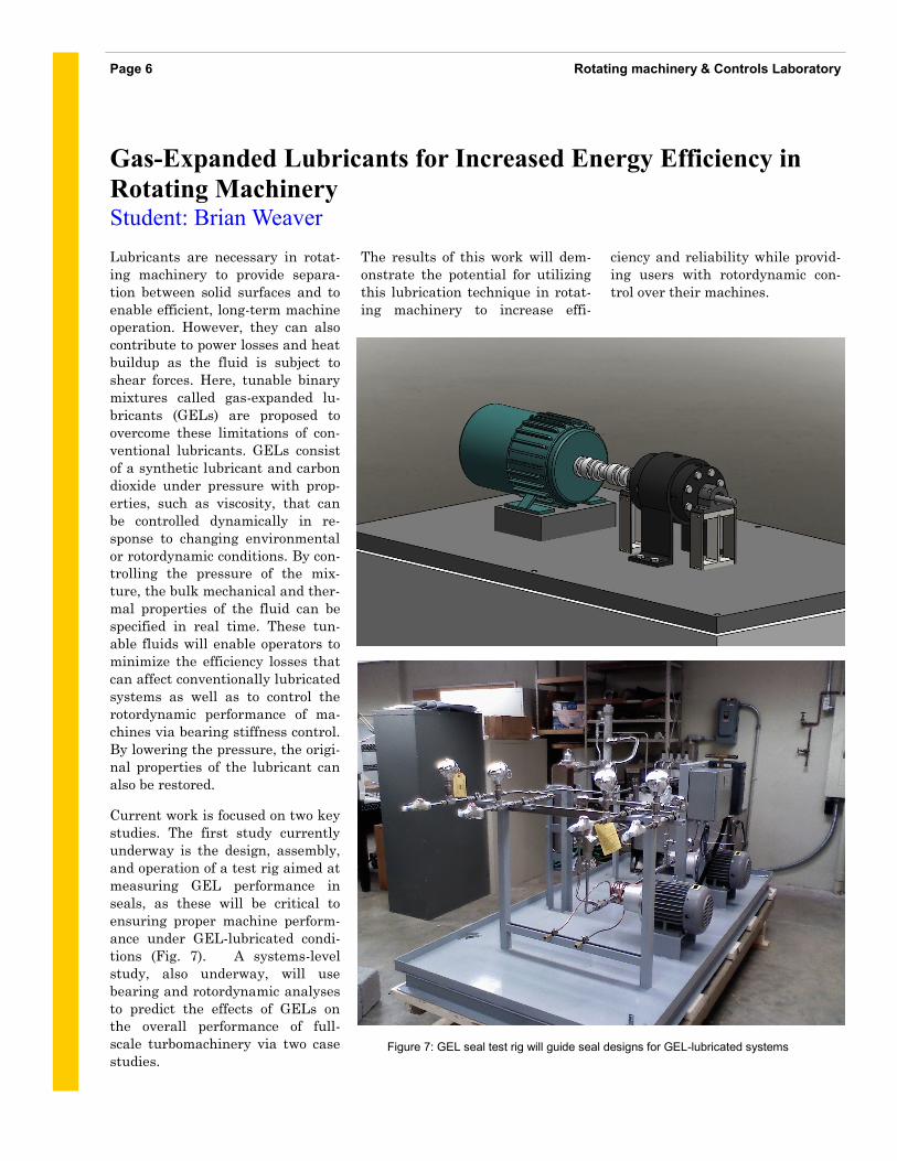
Current work is focused on two key
studies. The first study currently
underway is the design, assembly,
and operation of a test rig aimed at
measuring GEL performance in
seals, as these will be critical to
ensuring proper machine perform-
ance under GEL-lubricated condi-
tions (Fig. 7). A systems-level
study, also underway, will use
bearing and rotordynamic analyses
to predict the effects of GELs on
the overall performance of full-
scale turbomachinery via two case
studies.
The results of this work will dem-
onstrate the potential for utilizing
this lubrication technique in rotat-
ing machinery to increase effi-
Figure 7: GEL seal test rig will guide seal designs for GEL-lubricated systems
ciency and reliability while provid-
ing users with rotordynamic con-
trol over their machines.
The project explores the application
of the characteristic model based
all-coefficient adaptive control
(ACAC) method to the stabilization
of a flexible rotor AMB system. The
proposed characteristic modeling
process significantly simplifies the
modeling of a system with high
order complex dynamics by analyz-
ing its characteristics and consider-
ing the control requirement. A sec-
ond order time-varying difference
equation is able to model the rotor
AMB system in a position tracking/
keeping scenario. Based on the
characteristic model, characteristic
model based ACAC has fewer coef-
ficients to estimate and the control-
ler structure is much simpler com-
pared with conventional adaptive
control.
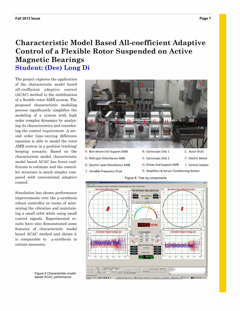
Simulation has shown performance
improvements over the µ-synthesis
robust controller in terms of mini-
mizing the vibration and maintain-
ing a small orbit while using small
control signals. Experimental re-
sults have also demonstrated some
features of characteristic model
based ACAC method and shown it
is comparable to µ-synthesis in
certain measures.
Page 7 Fall 2013 Issue
Figure 8: Test rig components
Characteristic Model Based All-coefficient Adaptive
Control of a Flexible Rotor Suspended on Active
Magnetic Bearings Student: (Dee) Long Di
Figure 9 Characteristic model based ACAC performance
Rotating machinery & Controls Laboratory Page 8
Robust Fractional Control for Flexible Rotor
supported by Magnetic Bearings Student: Parinya Anantachaisilp
The concept of a differentiation
operator with integer order is a
well-known fundamental tool of
modern calculus. Furthermore,
there is an extension to the situa-
tion where the order is arbitrary,
i.e., fractional order. Recent find-
ings support the notion that frac-
tional-order calculus should be em-
ployed where more accurate model-
ing and robust control are con-
cerned. Specifically, fractional-
order calculus found its way into
complex mathematical and physi-
cal problems. In the field of auto-
matic control fractional calculus is
used to obtain more accurate mod-
els, to develop new control strate-
gies, and to enhance the character-
istics of control systems.
In general, robust control design
can be achieved by using loop shap-
ing via frequency domain specifica-
tions such as sensitivity function,
gain crossover frequency, gain
margin, and phase margin. But in
most cases it is very time consum-
ing and relies on the experience of
the engineer to arrive at a control-
ler that provides performance ca-
Therefore, many researchers be-
gan to develop the automatic loop
shaping (with known controller
structure) which makes the proc-
ess of finding a controller more
effective. With that said, some-
times the automatic loop shaping
might not arrive with the satisfy-
ing controller. Thus, fractional
order controller has a good poten-
tial to provide a satisfying con-
troller since it has more space to
search for the parameters as well
as more flexibility in choosing
parameters for the controller.
The ongoing research into frac-
tional order control is being used
for the application of active mag-
netic bearings (AMB) in order to
test the capability of fractional
order control because this is a
very complex system - it is an
open loop unstable, non-
minimum phase, and multiple
input multiple output (MIMO)
system. Also, it has uncertainties
from frequency and cross-
coupling. These combine to create
a significant challenge for the
fractional order control concept.
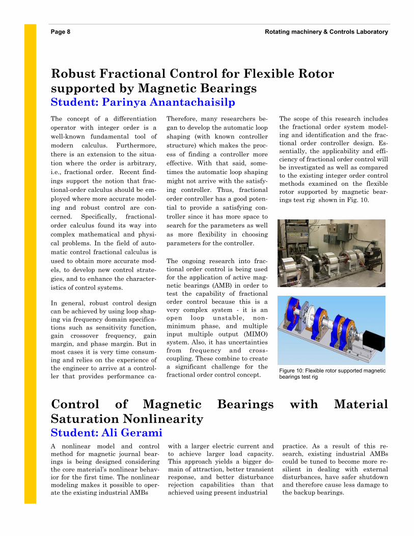
The scope of this research includes
the fractional order system model-
ing and identification and the frac-
tional order controller design. Es-
sentially, the applicability and effi-
ciency of fractional order control will
be investigated as well as compared
to the existing integer order control
methods examined on the flexible
rotor supported by magnetic bear-
ings test rig shown in Fig. 10.
Figure 10: Flexible rotor supported magnetic bearings test rig
Control of Magnetic Bearings with Material
Saturation Nonlinearity Student: Ali Gerami A nonlinear model and control
method for magnetic journal bear-
ings is being designed considering
the core material’s nonlinear behav-
ior for the first time. The nonlinear
modeling makes it possible to oper-
ate the existing industrial AMBs
with a larger electric current and
to achieve larger load capacity.
This approach yields a bigger do-
main of attraction, better transient
response, and better disturbance
rejection capabilities than that
achieved using present industrial
practice. As a result of this re-
search, existing industrial AMBs
could be tuned to become more re-
silient in dealing with external
disturbances, have safer shutdown
and therefore cause less damage to
the backup bearings.
Also smaller and lighter AMBs can
be designed by using the proposed
method.
The most appealing advantage of
using the nonlinear model is to
increase the disturbance rejection
potential. By using the proposed
nonlinear model, the system can
operate and survive an extra load
that is caused by a harsh situation
(storm on a wind turbine, turbu-
lences on an offshore drilling rig,
etc.).
As a tangible example, consider a
balance beam that resembles a
thrust magnetic bearing system
with a backup ball bearing sitting
at 50% of the airgap and an initial
offset (40% of the airgap). While
the system is operating, a pulse-
like disturbance upsets the system.
The simulation result is shown in
Fig. 11. The top graph is a com-
parison of the time response of the
systems with common linear mod-
els and the proposed nonlinear
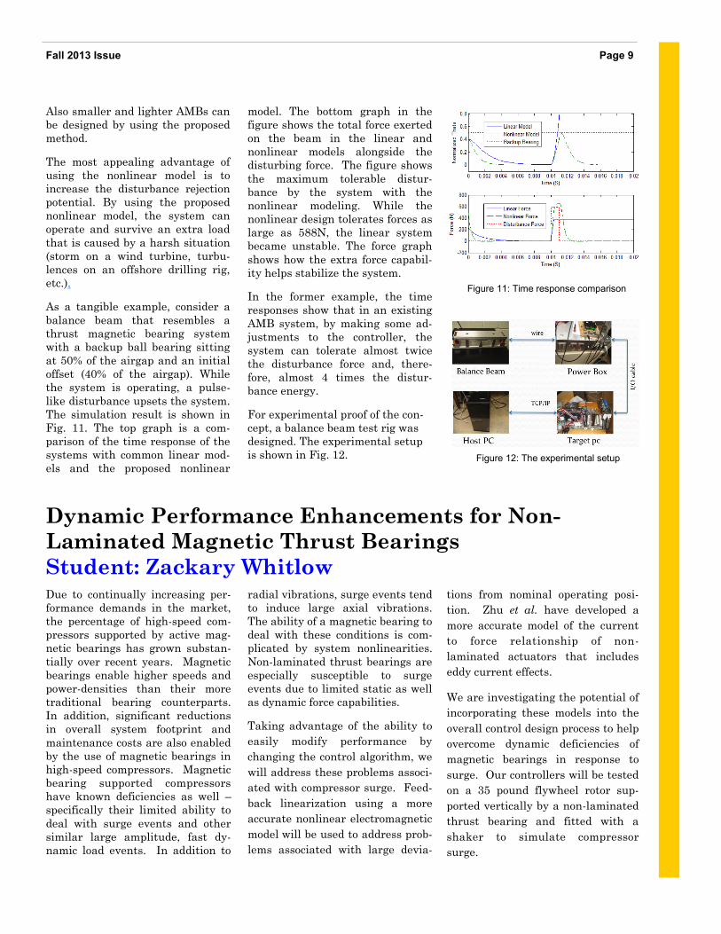
model. The bottom graph in the
figure shows the total force exerted
on the beam in the linear and
nonlinear models alongside the
disturbing force. The figure shows
the maximum tolerable distur-
bance by the system with the
nonlinear modeling. While the
nonlinear design tolerates forces as
large as 588N, the linear system
became unstable. The force graph
shows how the extra force capabil-
ity helps stabilize the system.
In the former example, the time
responses show that in an existing
AMB system, by making some ad-
justments to the controller, the
system can tolerate almost twice
the disturbance force and, there-
fore, almost 4 times the distur-
bance energy.
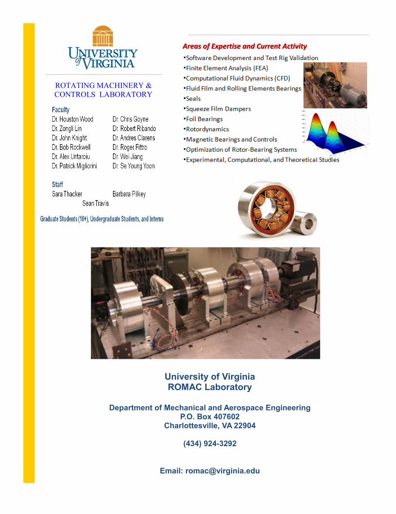
For experimental proof of the con-
cept, a balance beam test rig was
designed. The experimental setup
is shown in Fig. 12.
tions from nominal operating posi-
tion. Zhu et al. have developed a
more accurate model of the current
to force relationship of non-
laminated actuators that includes
eddy current effects.
We are investigating the potential of
incorporating these models into the
overall control design process to help
overcome dynamic deficiencies of
magnetic bearings in response to
surge. Our controllers will be tested
on a 35 pound flywheel rotor sup-
ported vertically by a non-laminated
thrust bearing and fitted with a
shaker to simulate compressor
surge.
Due to continually increasing per-
formance demands in the market,
the percentage of high-speed com-
pressors supported by active mag-
netic bearings has grown substan-
tially over recent years. Magnetic
bearings enable higher speeds and
power-densities than their more
traditional bearing counterparts.
In addition, significant reductions
in overall system footprint and
maintenance costs are also enabled
by the use of magnetic bearings in
high-speed compressors. Magnetic
bearing supported compressors
have known deficiencies as well –
specifically their limited ability to
deal with surge events and other
similar large amplitude, fast dy-
namic load events. In addition to
radial vibrations, surge events tend
to induce large axial vibrations.
The ability of a magnetic bearing to
deal with these conditions is com-
plicated by system nonlinearities.
Non-laminated thrust bearings are
especially susceptible to surge
events due to limited static as well
as dynamic force capabilities.
Taking advantage of the ability to
easily modify performance by
changing the control algorithm, we
will address these problems associ-
ated with compressor surge. Feed-
back linearization using a more
accurate nonlinear electromagnetic
model will be used to address prob-
lems associated with large devia-
Page 9 Fall 2013 Issue
Figure 12: The experimental setup
Dynamic Performance Enhancements for Non-
Laminated Magnetic Thrust Bearings
Student: Zackary Whitlow
Figure 11: Time response comparison
University of Virginia ROMAC Laboratory
Department of Mechanical and Aerospace Engineering
P.O. Box 407602 Charlottesville, VA 22904
(434) 924-3292
Email: [email protected]
Areas of Expertise and Current ActivityAreas of Expertise and Current Activity
ROTATING MACHINERY &
CONTROLS LABORATORY