RollView User Manualcommunity.snellgroup.com/product_handbooks/CONTROL_AND...2.2.6 Cascade Displays...
99
www.s-a-m.com User Manual RollView RollCall Alarm Monitor
Transcript of RollView User Manualcommunity.snellgroup.com/product_handbooks/CONTROL_AND...2.2.6 Cascade Displays...

www.s-a-m.com
User Manual
RollViewRollCall Alarm Monitor

RollView User Manual Information and Notices
Issue 3 Rev 1 Page 2 © 2015 SAM
Information and Notices
Copyright and Disclaimer
Copyright protection claimed includes all forms and matters of copyrightable material and information now allowed by statutory or judicial law or hereinafter granted, including without limitation, material generated from the software programs which are displayed on the screen such as icons, screen display looks etc.
Information in this manual and software are subject to change without notice and does not represent a commitment on the part of SAM. The software described in this manual is furnished under a license agreement and can not be reproduced or copied in any manner without prior agreement with SAM, or their authorized agents.
Reproduction or disassembly of embedded computer programs or algorithms prohibited.
No part of this publication can be transmitted or reproduced in any form or by any means, electronic or mechanical, including photocopy, recording or any information storage and retrieval system, without permission being granted, in writing, by the publishers or their authorized agents.
SAM operates a policy of continuous improvement and development. SAM reserves the right to make changes and improvements to any of the products described in this document without prior notice.
Contact Details
Customer Support
For details of our Regional Customer Support Offices please visit the SAM web site and navigate to Support/Contact Support.
www.s-a-m.com/support/contact-support/
Customers with a support contract should call their personalized number, which can be found in their contract, and be ready to provide their contract number and details.

RollView User Manual Contents
Contents
Information and Notices . . . . . . . . . . . . . . . . . . . . . . . . . . . . . . . . . . . . . . . . . . . . . . . . 2Copyright and Disclaimer . . . . . . . . . . . . . . . . . . . . . . . . . . . . . . . . . . . . . . . . . . . . . . 2Contact Details . . . . . . . . . . . . . . . . . . . . . . . . . . . . . . . . . . . . . . . . . . . . . . . . . . . . . . 2
1. Introduction. . . . . . . . . . . . . . . . . . . . . . . . . . . . . . . . . . . . . . . . . . . . . . . . . . . . . . . . . 61.1 Installation and Prerequisites . . . . . . . . . . . . . . . . . . . . . . . . . . . . . . . . . . . . . . . . 6
2. General Operation . . . . . . . . . . . . . . . . . . . . . . . . . . . . . . . . . . . . . . . . . . . . . . . . . . . 72.1 Screen Components . . . . . . . . . . . . . . . . . . . . . . . . . . . . . . . . . . . . . . . . . . . . . . . 72.2 Main Toolbars . . . . . . . . . . . . . . . . . . . . . . . . . . . . . . . . . . . . . . . . . . . . . . . . . . . . 8
2.2.1 New . . . . . . . . . . . . . . . . . . . . . . . . . . . . . . . . . . . . . . . . . . . . . . . . . . . . . . . 82.2.2 Open . . . . . . . . . . . . . . . . . . . . . . . . . . . . . . . . . . . . . . . . . . . . . . . . . . . . . . 82.2.3 Save . . . . . . . . . . . . . . . . . . . . . . . . . . . . . . . . . . . . . . . . . . . . . . . . . . . . . . . 82.2.4 Print . . . . . . . . . . . . . . . . . . . . . . . . . . . . . . . . . . . . . . . . . . . . . . . . . . . . . . . 82.2.5 Log Logic . . . . . . . . . . . . . . . . . . . . . . . . . . . . . . . . . . . . . . . . . . . . . . . . . . . 82.2.6 Cascade . . . . . . . . . . . . . . . . . . . . . . . . . . . . . . . . . . . . . . . . . . . . . . . . . . . . 82.2.7 Tile Horizontally . . . . . . . . . . . . . . . . . . . . . . . . . . . . . . . . . . . . . . . . . . . . . . 82.2.8 Tile Vertically . . . . . . . . . . . . . . . . . . . . . . . . . . . . . . . . . . . . . . . . . . . . . . . . 82.2.9 Minimize/Un-Minimize . . . . . . . . . . . . . . . . . . . . . . . . . . . . . . . . . . . . . . . . . 82.2.10 Fullscreen . . . . . . . . . . . . . . . . . . . . . . . . . . . . . . . . . . . . . . . . . . . . . . . . . . 8
2.3 Customize Screen Layout and Color Theme . . . . . . . . . . . . . . . . . . . . . . . . . . . . 92.3.1 Docking Windows . . . . . . . . . . . . . . . . . . . . . . . . . . . . . . . . . . . . . . . . . . . . . 92.3.2 Customize Toolbars. . . . . . . . . . . . . . . . . . . . . . . . . . . . . . . . . . . . . . . . . . . 102.3.3 Set a Color Theme . . . . . . . . . . . . . . . . . . . . . . . . . . . . . . . . . . . . . . . . . . . .11
3. Configuring RollView . . . . . . . . . . . . . . . . . . . . . . . . . . . . . . . . . . . . . . . . . . . . . . . . 123.1 Set the Log Server Connection . . . . . . . . . . . . . . . . . . . . . . . . . . . . . . . . . . . . . . 12
3.1.1 TCP/IP Input . . . . . . . . . . . . . . . . . . . . . . . . . . . . . . . . . . . . . . . . . . . . . . . . 123.1.2 File Input . . . . . . . . . . . . . . . . . . . . . . . . . . . . . . . . . . . . . . . . . . . . . . . . . . . 133.1.3 Control Connection . . . . . . . . . . . . . . . . . . . . . . . . . . . . . . . . . . . . . . . . . . . 13
3.2 Set up the Unit List . . . . . . . . . . . . . . . . . . . . . . . . . . . . . . . . . . . . . . . . . . . . . . . 143.2.1 Set up Keyword Headers . . . . . . . . . . . . . . . . . . . . . . . . . . . . . . . . . . . . . . 143.2.2 Special Keyword Headers . . . . . . . . . . . . . . . . . . . . . . . . . . . . . . . . . . . . . . 16
3.3 Set the Global Time Format . . . . . . . . . . . . . . . . . . . . . . . . . . . . . . . . . . . . . . . . 183.4 RollMap Client Logging . . . . . . . . . . . . . . . . . . . . . . . . . . . . . . . . . . . . . . . . . . . . 183.5 Snap Shot IDs . . . . . . . . . . . . . . . . . . . . . . . . . . . . . . . . . . . . . . . . . . . . . . . . . . . 203.6 Enable SNMP . . . . . . . . . . . . . . . . . . . . . . . . . . . . . . . . . . . . . . . . . . . . . . . . . . . 203.7 Set up Global Alarm Triggers and Actions . . . . . . . . . . . . . . . . . . . . . . . . . . . . . 20
3.7.1 About Alarm Triggers . . . . . . . . . . . . . . . . . . . . . . . . . . . . . . . . . . . . . . . . . 213.7.2 About Alarm Actions . . . . . . . . . . . . . . . . . . . . . . . . . . . . . . . . . . . . . . . . . . 223.7.3 Add an Alarm Trigger . . . . . . . . . . . . . . . . . . . . . . . . . . . . . . . . . . . . . . . . . 223.7.4 Configure Alarm Triggers . . . . . . . . . . . . . . . . . . . . . . . . . . . . . . . . . . . . . . 233.7.5 Add an Alarm Action . . . . . . . . . . . . . . . . . . . . . . . . . . . . . . . . . . . . . . . . . . 263.7.6 Alarm Action Operations . . . . . . . . . . . . . . . . . . . . . . . . . . . . . . . . . . . . . . . 263.7.7 Trigger Operations . . . . . . . . . . . . . . . . . . . . . . . . . . . . . . . . . . . . . . . . . . . 263.7.8 Multi Alarm Triggers . . . . . . . . . . . . . . . . . . . . . . . . . . . . . . . . . . . . . . . . . . 263.7.9 Configure Alarm Actions . . . . . . . . . . . . . . . . . . . . . . . . . . . . . . . . . . . . . . . 27
3.8 Configure Email Messages . . . . . . . . . . . . . . . . . . . . . . . . . . . . . . . . . . . . . . . . . 443.8.1 Create a Transport Profile . . . . . . . . . . . . . . . . . . . . . . . . . . . . . . . . . . . . . . 453.8.2 Create a Message Profile . . . . . . . . . . . . . . . . . . . . . . . . . . . . . . . . . . . . . . 46
3.9 Set up Search Paths . . . . . . . . . . . . . . . . . . . . . . . . . . . . . . . . . . . . . . . . . . . . . . 483.10 Configure Shortcut Links . . . . . . . . . . . . . . . . . . . . . . . . . . . . . . . . . . . . . . . . . . 493.11 Other Configuration Options . . . . . . . . . . . . . . . . . . . . . . . . . . . . . . . . . . . . . . . 50
4. System Alarms Window. . . . . . . . . . . . . . . . . . . . . . . . . . . . . . . . . . . . . . . . . . . . . . 514.1 Description . . . . . . . . . . . . . . . . . . . . . . . . . . . . . . . . . . . . . . . . . . . . . . . . . . . . . 514.2 Connect to Units . . . . . . . . . . . . . . . . . . . . . . . . . . . . . . . . . . . . . . . . . . . . . . . . . 514.3 Mask Units. . . . . . . . . . . . . . . . . . . . . . . . . . . . . . . . . . . . . . . . . . . . . . . . . . . . . . 51
Issue 3 Rev 1 Page 3 © 2015 SAM

RollView User Manual Contents
4.3.1 Mask Setup . . . . . . . . . . . . . . . . . . . . . . . . . . . . . . . . . . . . . . . . . . . . . . . . . 514.3.2 Mask Unit / Unmask Unit. . . . . . . . . . . . . . . . . . . . . . . . . . . . . . . . . . . . . . . 524.3.3 Mask Unit Until Green . . . . . . . . . . . . . . . . . . . . . . . . . . . . . . . . . . . . . . . . . 524.3.4 Mask Unit Until Time . . . . . . . . . . . . . . . . . . . . . . . . . . . . . . . . . . . . . . . . . . 524.3.5 Mask Cell / Unmask Cell . . . . . . . . . . . . . . . . . . . . . . . . . . . . . . . . . . . . . . . 524.3.6 Mask Cell Until Green . . . . . . . . . . . . . . . . . . . . . . . . . . . . . . . . . . . . . . . . . 524.3.7 Mask Cell Until Time . . . . . . . . . . . . . . . . . . . . . . . . . . . . . . . . . . . . . . . . . . 524.3.8 Unmask All Cells . . . . . . . . . . . . . . . . . . . . . . . . . . . . . . . . . . . . . . . . . . . . . 52
4.4 Query the State of a Unit . . . . . . . . . . . . . . . . . . . . . . . . . . . . . . . . . . . . . . . . . . . 534.5 Change View Options . . . . . . . . . . . . . . . . . . . . . . . . . . . . . . . . . . . . . . . . . . . . . 53
4.5.1 Aggregate State. . . . . . . . . . . . . . . . . . . . . . . . . . . . . . . . . . . . . . . . . . . . . . 534.5.2 Highlight Changes. . . . . . . . . . . . . . . . . . . . . . . . . . . . . . . . . . . . . . . . . . . . 534.5.3 Auto-arrange Column Widths . . . . . . . . . . . . . . . . . . . . . . . . . . . . . . . . . . . 534.5.4 Show Error State in Network Tree. . . . . . . . . . . . . . . . . . . . . . . . . . . . . . . . 54
4.6 Override Keyword Headers . . . . . . . . . . . . . . . . . . . . . . . . . . . . . . . . . . . . . . . . . 544.7 Log Field Logic . . . . . . . . . . . . . . . . . . . . . . . . . . . . . . . . . . . . . . . . . . . . . . . . . . 544.8 View Unit Details . . . . . . . . . . . . . . . . . . . . . . . . . . . . . . . . . . . . . . . . . . . . . . . . . 574.9 Printing . . . . . . . . . . . . . . . . . . . . . . . . . . . . . . . . . . . . . . . . . . . . . . . . . . . . . . . . 58
4.9.1 Page Setup Options . . . . . . . . . . . . . . . . . . . . . . . . . . . . . . . . . . . . . . . . . . 584.9.2 Printer Setup Options . . . . . . . . . . . . . . . . . . . . . . . . . . . . . . . . . . . . . . . . . 584.9.3 Print Preview . . . . . . . . . . . . . . . . . . . . . . . . . . . . . . . . . . . . . . . . . . . . . . . . 584.9.4 Print . . . . . . . . . . . . . . . . . . . . . . . . . . . . . . . . . . . . . . . . . . . . . . . . . . . . . . . 58
4.10 User Alarms. . . . . . . . . . . . . . . . . . . . . . . . . . . . . . . . . . . . . . . . . . . . . . . . . . . . 594.10.1 Set up an Alarm Document . . . . . . . . . . . . . . . . . . . . . . . . . . . . . . . . . . . . 594.10.2 Unit State. . . . . . . . . . . . . . . . . . . . . . . . . . . . . . . . . . . . . . . . . . . . . . . . . . 594.10.3 Mask/Unmask Units . . . . . . . . . . . . . . . . . . . . . . . . . . . . . . . . . . . . . . . . . 604.10.4 Set Viewing Mask . . . . . . . . . . . . . . . . . . . . . . . . . . . . . . . . . . . . . . . . . . . 604.10.5 Move Faulty Units . . . . . . . . . . . . . . . . . . . . . . . . . . . . . . . . . . . . . . . . . . . 604.10.6 New Alarm. . . . . . . . . . . . . . . . . . . . . . . . . . . . . . . . . . . . . . . . . . . . . . . . . 614.10.7 Hide the Mask Window . . . . . . . . . . . . . . . . . . . . . . . . . . . . . . . . . . . . . . . 614.10.8 Print the User Alarm window. . . . . . . . . . . . . . . . . . . . . . . . . . . . . . . . . . . 61
4.11 Configure Headers . . . . . . . . . . . . . . . . . . . . . . . . . . . . . . . . . . . . . . . . . . . . . . 624.11.1 Select Columns . . . . . . . . . . . . . . . . . . . . . . . . . . . . . . . . . . . . . . . . . . . . . 624.11.2 Deselect Columns After Pin. . . . . . . . . . . . . . . . . . . . . . . . . . . . . . . . . . . . 634.11.3 Edit Header . . . . . . . . . . . . . . . . . . . . . . . . . . . . . . . . . . . . . . . . . . . . . . . . 634.11.4 Create All Headers . . . . . . . . . . . . . . . . . . . . . . . . . . . . . . . . . . . . . . . . . . 634.11.5 Sort Headers By Name . . . . . . . . . . . . . . . . . . . . . . . . . . . . . . . . . . . . . . . 634.11.6 Delete Unused Headers . . . . . . . . . . . . . . . . . . . . . . . . . . . . . . . . . . . . . . 634.11.7 Fix Header Position . . . . . . . . . . . . . . . . . . . . . . . . . . . . . . . . . . . . . . . . . . 634.11.8 Auto-arrange Column Widths . . . . . . . . . . . . . . . . . . . . . . . . . . . . . . . . . . 63
5. Network Tree. . . . . . . . . . . . . . . . . . . . . . . . . . . . . . . . . . . . . . . . . . . . . . . . . . . . . . . 645.1 Description . . . . . . . . . . . . . . . . . . . . . . . . . . . . . . . . . . . . . . . . . . . . . . . . . . . . . 645.2 Auto Discovery . . . . . . . . . . . . . . . . . . . . . . . . . . . . . . . . . . . . . . . . . . . . . . . . . . 65
6. User Tree . . . . . . . . . . . . . . . . . . . . . . . . . . . . . . . . . . . . . . . . . . . . . . . . . . . . . . . . . . 666.1 Description . . . . . . . . . . . . . . . . . . . . . . . . . . . . . . . . . . . . . . . . . . . . . . . . . . . . . 66
6.1.1 Filtered Groups . . . . . . . . . . . . . . . . . . . . . . . . . . . . . . . . . . . . . . . . . . . . . . 67
7. History Tabs . . . . . . . . . . . . . . . . . . . . . . . . . . . . . . . . . . . . . . . . . . . . . . . . . . . . . . . 707.1 Description . . . . . . . . . . . . . . . . . . . . . . . . . . . . . . . . . . . . . . . . . . . . . . . . . . . . . 707.2 Managing History Tabs . . . . . . . . . . . . . . . . . . . . . . . . . . . . . . . . . . . . . . . . . . . . 70
7.2.1 Create Complimentary Tab . . . . . . . . . . . . . . . . . . . . . . . . . . . . . . . . . . . . . 707.2.2 Create New Tab . . . . . . . . . . . . . . . . . . . . . . . . . . . . . . . . . . . . . . . . . . . . . 707.2.3 Move Tab Order Left/Right . . . . . . . . . . . . . . . . . . . . . . . . . . . . . . . . . . . . . 717.2.4 Delete Tab . . . . . . . . . . . . . . . . . . . . . . . . . . . . . . . . . . . . . . . . . . . . . . . . . . 717.2.5 History Tab Log File Setup . . . . . . . . . . . . . . . . . . . . . . . . . . . . . . . . . . . . . 717.2.6 Columns . . . . . . . . . . . . . . . . . . . . . . . . . . . . . . . . . . . . . . . . . . . . . . . . . . . 727.2.7 History Tab Properties. . . . . . . . . . . . . . . . . . . . . . . . . . . . . . . . . . . . . . . . . 74
7.3 History Tab Example . . . . . . . . . . . . . . . . . . . . . . . . . . . . . . . . . . . . . . . . . . . . . . 75
Issue 3 Rev 1 Page 4 © 2015 SAM

RollView User Manual Contents
Appendix A. RollView Command Line Parameters . . . . . . . . . . . . . . . . . . . . . . . . . . 78
Appendix B. SNMP Setup for RollView . . . . . . . . . . . . . . . . . . . . . . . . . . . . . . . . . . . 81B.1 Installing SNMP Services for Windows XP . . . . . . . . . . . . . . . . . . . . . . . . . . . . . 81B.2 Installing SNMP Services for Windows 7/2008. . . . . . . . . . . . . . . . . . . . . . . . . . 84
Appendix C. Integrating RollView with Volicon Observer . . . . . . . . . . . . . . . . . . . . 87C.1 Overview. . . . . . . . . . . . . . . . . . . . . . . . . . . . . . . . . . . . . . . . . . . . . . . . . . . . . . . 87C.2 Configuring Shortcut Links . . . . . . . . . . . . . . . . . . . . . . . . . . . . . . . . . . . . . . . . . 87C.3 Setting up the INFORMATION2 Log Field . . . . . . . . . . . . . . . . . . . . . . . . . . . . . 88C.4 Setting up the RollView History Tabs . . . . . . . . . . . . . . . . . . . . . . . . . . . . . . . . . 89C.5 Working with Volicon Observer. . . . . . . . . . . . . . . . . . . . . . . . . . . . . . . . . . . . . . 89
Appendix D. Virtual Units . . . . . . . . . . . . . . . . . . . . . . . . . . . . . . . . . . . . . . . . . . . . . . 90D.1 Overview. . . . . . . . . . . . . . . . . . . . . . . . . . . . . . . . . . . . . . . . . . . . . . . . . . . . . . . 90D.2 Troubleshooting . . . . . . . . . . . . . . . . . . . . . . . . . . . . . . . . . . . . . . . . . . . . . . . . . 90
D.2.1 Cannot see virtual unit in User Alarms View . . . . . . . . . . . . . . . . . . . . . 90D.2.2 Cannot see the virtual header in User Alarms View . . . . . . . . . . . . . . . 90
Appendix E. Rules Engine . . . . . . . . . . . . . . . . . . . . . . . . . . . . . . . . . . . . . . . . . . . . . . 91E.1 Overview . . . . . . . . . . . . . . . . . . . . . . . . . . . . . . . . . . . . . . . . . . . . . . . . . . . . . . . 91E.2 Rule Editor . . . . . . . . . . . . . . . . . . . . . . . . . . . . . . . . . . . . . . . . . . . . . . . . . . . . . 91
E.2.1 Rule Editor Settings . . . . . . . . . . . . . . . . . . . . . . . . . . . . . . . . . . . . . . . . 91E.3 Example Rules . . . . . . . . . . . . . . . . . . . . . . . . . . . . . . . . . . . . . . . . . . . . . . . . . . 92
E.3.1 Example 1 . . . . . . . . . . . . . . . . . . . . . . . . . . . . . . . . . . . . . . . . . . . . . . . 92E.3.2 Example 2 . . . . . . . . . . . . . . . . . . . . . . . . . . . . . . . . . . . . . . . . . . . . . . . 93
Appendix F. RollView Parameterization . . . . . . . . . . . . . . . . . . . . . . . . . . . . . . . . . . . 97F.1 Relative Paths . . . . . . . . . . . . . . . . . . . . . . . . . . . . . . . . . . . . . . . . . . . . . . . . . . . 97F.2 Search Paths. . . . . . . . . . . . . . . . . . . . . . . . . . . . . . . . . . . . . . . . . . . . . . . . . . . . 97F.3 Macros . . . . . . . . . . . . . . . . . . . . . . . . . . . . . . . . . . . . . . . . . . . . . . . . . . . . . . . . 97F.4 Dynamic Log Field Insertion . . . . . . . . . . . . . . . . . . . . . . . . . . . . . . . . . . . . . . . . 98F.5 Dynamic Data Insertion. . . . . . . . . . . . . . . . . . . . . . . . . . . . . . . . . . . . . . . . . . . . 98
Issue 3 Rev 1 Page 5 © 2015 SAM
RollView User Manual Introduction
Issue 3 Rev 1 Page 6 © 2015 SAM
1. Introduction
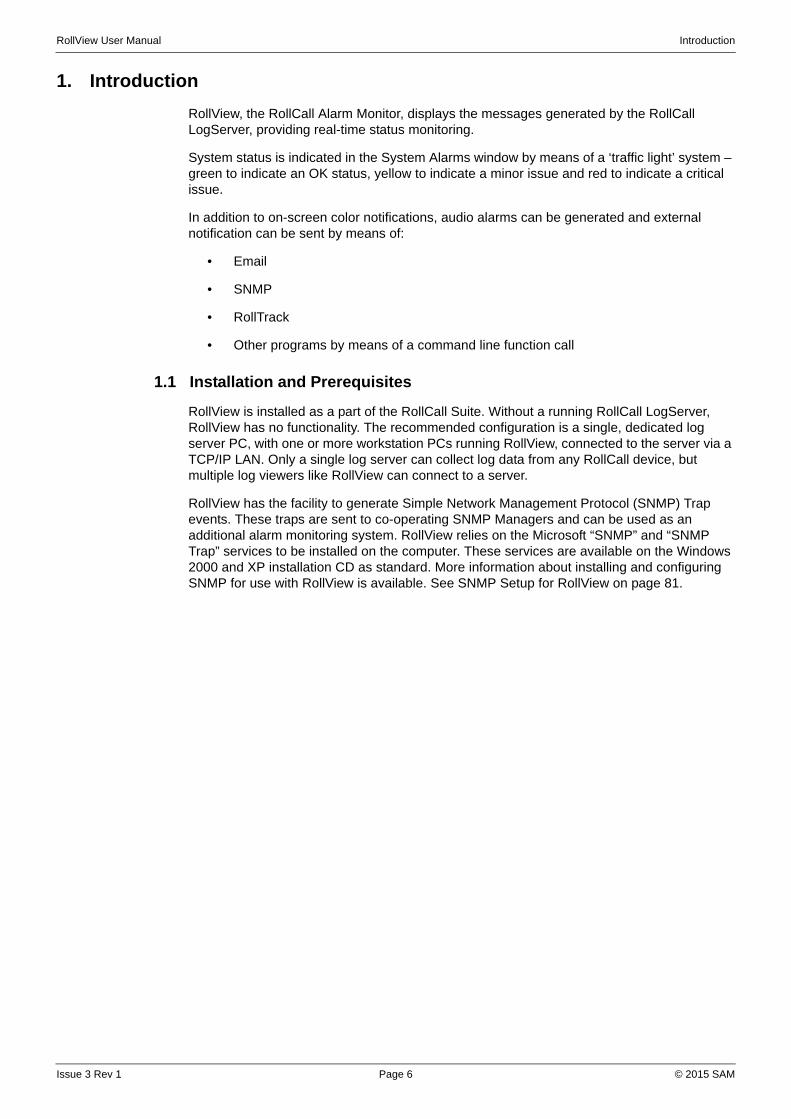
RollView, the RollCall Alarm Monitor, displays the messages generated by the RollCall LogServer, providing real-time status monitoring.
System status is indicated in the System Alarms window by means of a ‘traffic light’ system – green to indicate an OK status, yellow to indicate a minor issue and red to indicate a critical issue.
In addition to on-screen color notifications, audio alarms can be generated and external notification can be sent by means of:
• SNMP
• RollTrack
• Other programs by means of a command line function call
1.1 Installation and Prerequisites
RollView is installed as a part of the RollCall Suite. Without a running RollCall LogServer, RollView has no functionality. The recommended configuration is a single, dedicated log server PC, with one or more workstation PCs running RollView, connected to the server via a TCP/IP LAN. Only a single log server can collect log data from any RollCall device, but multiple log viewers like RollView can connect to a server.
RollView has the facility to generate Simple Network Management Protocol (SNMP) Trap events. These traps are sent to co-operating SNMP Managers and can be used as an additional alarm monitoring system. RollView relies on the Microsoft “SNMP” and “SNMP Trap” services to be installed on the computer. These services are available on the Windows 2000 and XP installation CD as standard. More information about installing and configuring SNMP for use with RollView is available. See SNMP Setup for RollView on page 81.
RollView User Manual General Operation
2. General Operation
2.1 Screen Components
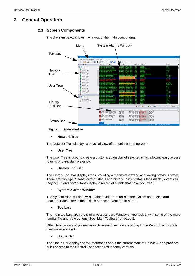
The diagram below shows the layout of the main components.
• Network Tree
The Network Tree displays a physical view of the units on the network.
• User Tree
The User Tree is used to create a customized display of selected units, allowing easy access to units of particular relevance.
• History Tool Bar
The History Tool Bar displays tabs providing a means of viewing and saving previous states. There are two type of tabs, current status and history. Current status tabs display events as they occur, and history tabs display a record of events that have occurred.
• System Alarms Window
The System Alarms Window is a table made from units in the system and their alarm headers. Each entry in the table is a trigger event for an alarm.
• Toolbars
The main toolbars are very similar to a standard Windows-type toolbar with some of the more familiar file and view options. See “Main Toolbars” on page 8.
Other Toolbars are explained in each relevant section according to the Window with which they are associated.
• Status Bar
The Status Bar displays some information about the current state of RollView, and provides quick access to the Control Connection redundancy controls.
Figure 1 Main Window
Toolbars
Network Tree
History Tool Bar
System Alarms WindowMenu
Status Bar
User Tree
Issue 3 Rev 1 Page 7 © 2015 SAM
RollView User Manual General Operation
• Menus
A set of menus display at the top of the screen. The majority of these menus are similar to standard Windows type menus and need no further explanation here.
The Configuration menu provides shortcuts to some of the features available in the various Windows. See “Configuring RollView” on page 12.
Right-clicking in a window displays a further menu related to that window.
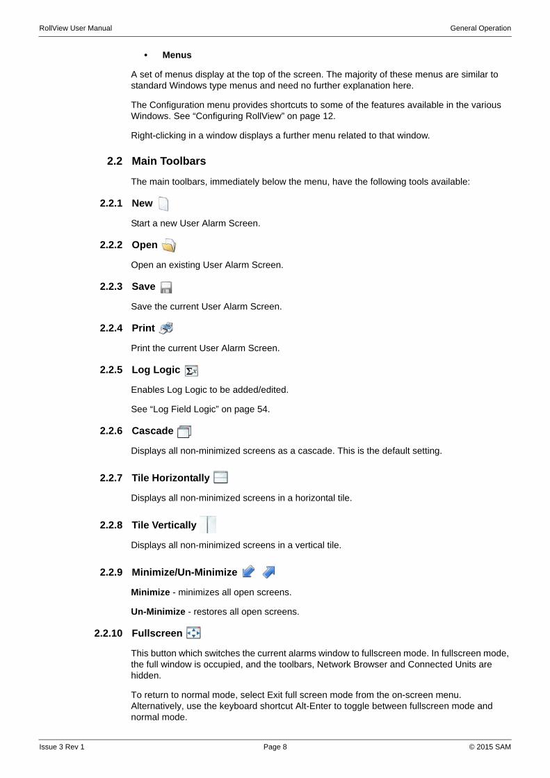
2.2 Main Toolbars
The main toolbars, immediately below the menu, have the following tools available:
2.2.1 New
Start a new User Alarm Screen.
2.2.2 Open
Open an existing User Alarm Screen.
2.2.3 Save
Save the current User Alarm Screen.
2.2.4 Print
Print the current User Alarm Screen.
2.2.5 Log Logic
Enables Log Logic to be added/edited.
See “Log Field Logic” on page 54.
2.2.6 Cascade
Displays all non-minimized screens as a cascade. This is the default setting.
2.2.7 Tile Horizontally
Displays all non-minimized screens in a horizontal tile.
2.2.8 Tile Vertically
Displays all non-minimized screens in a vertical tile.
2.2.9 Minimize/Un-Minimize
Minimize - minimizes all open screens.
Un-Minimize - restores all open screens.
2.2.10 Fullscreen
This button which switches the current alarms window to fullscreen mode. In fullscreen mode, the full window is occupied, and the toolbars, Network Browser and Connected Units are hidden.
To return to normal mode, select Exit full screen mode from the on-screen menu. Alternatively, use the keyboard shortcut Alt-Enter to toggle between fullscreen mode and normal mode.
Issue 3 Rev 1 Page 8 © 2015 SAM
RollView User Manual General Operation
2.3 Customize Screen Layout and Color Theme
The size and position of the component windows within the screen may be changed to suit a particular application. Tool bars can be configured to show only those items that are being used. Choose from the dark and light color themes according to preference.
Any changes to the windows and toolbars are saved on closing RollView, and are restored automatically when reopening the application.
The layout settings are stored in an external file that, if required, can be copied to other RollView clients to give a standard look across clients, or, a number of alternative layouts can be saved in other folders, and restored depending on the application.
To reference an alternative saved layout file: in the Configuration.cfg file enter the following line in the [Rollmaster] section:
LayoutFile=(insert the path of the saved file)Layout.xml
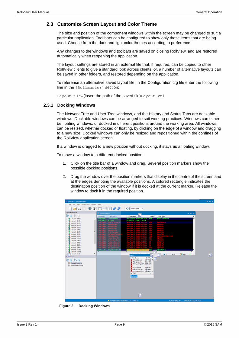
2.3.1 Docking Windows
The Network Tree and User Tree windows, and the History and Status Tabs are dockable windows. Dockable windows can be arranged to suit working practices. Windows can either be floating windows, or docked in different positions around the working area. All windows can be resized, whether docked or floating, by clicking on the edge of a window and dragging to a new size. Docked windows can only be resized and repositioned within the confines of the RollView application screen.
If a window is dragged to a new position without docking, it stays as a floating window.
To move a window to a different docked position:
1. Click on the title bar of a window and drag. Several position markers show the possible docking positions.
2. Drag the window over the position markers that display in the centre of the screen and at the edges denoting the available positions. A colored rectangle indicates the destination position of the window if it is docked at the current marker. Release the window to dock it in the required position.
Figure 2 Docking Windows
Issue 3 Rev 1 Page 9 © 2015 SAM

RollView User Manual General Operation
Docking a window directly over an existing window, causes the two windows to be tabbed allowing selection of either of them.
Docked windows can be pinned to the edge of the screen so that they become tabbed windows.
• To pin a window to the edge of the screen, click the button.
• To restore the window, click the button.
2.3.2 Customize Toolbars
The buttons on the toolbars at the top of the screen can be customized to remove or add buttons, as required.
To remove buttons from a toolbar:
1. Click on at the right of a toolbar.
2. Click on Add or Remove Buttons.
3. Select the toolbar to customize.
4. From the list of buttons that displays uncheck the buttons not required in the toolbar.
To add buttons back in to a toolbar:
1. Click on at the right of a toolbar.
2. Click on Add or Remove Buttons.
3. Select the toolbar to customize.
Figure 3 Pinned Windows
Figure 4 Add and Remove Toolbar Buttons
Issue 3 Rev 1 Page 10 © 2015 SAM
RollView User Manual General Operation
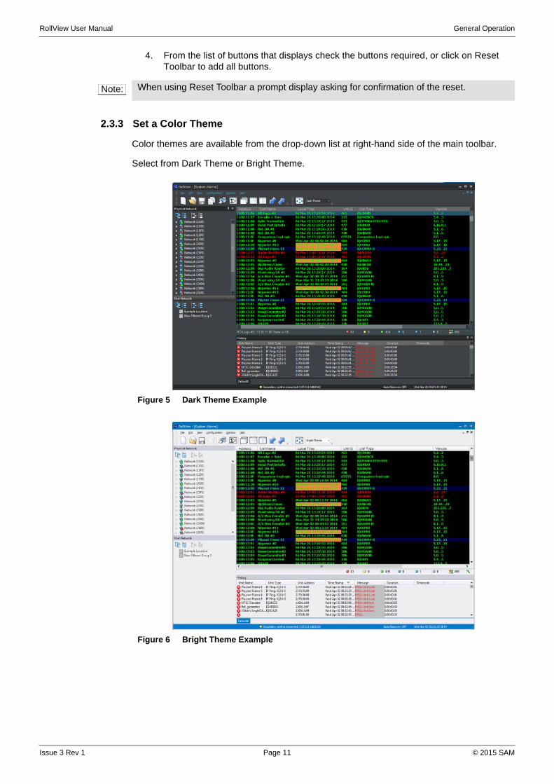
4. From the list of buttons that displays check the buttons required, or click on Reset Toolbar to add all buttons.
2.3.3 Set a Color Theme
Color themes are available from the drop-down list at right-hand side of the main toolbar.
Select from Dark Theme or Bright Theme.
Note: When using Reset Toolbar a prompt display asking for confirmation of the reset.
Figure 5 Dark Theme Example
Figure 6 Bright Theme Example
Issue 3 Rev 1 Page 11 © 2015 SAM

RollView User Manual Configuring RollView
3. Configuring RollView
3.1 Set the Log Server Connection
In order for RollView to have any functionality, it must be connected to a RollCall Log Server, which is in turn connected to and monitoring a RollCall enabled network.
To configure RollView's connection to the Log Server:
• From the Configuration menu, select Log Server Connection.
The Log Server Connection dialog displays.
Figure 7 Log Server Connection
The configuration for the current status file allows selection of saved file for input, or by direct TCP/IP input.
The Control Connection is the address of the RollCall Network proxy or chassis. That is, the same address used to connect the RollCall Control Panel to the network.
3.1.1 TCP/IP Input
Check the Use TCP/IP Log server checkbox to make a TCP/IP connection to a RollCall Log Server. This has significant speed improvements over the polling status file method above, and is recommended for all installations.
When using a TCP/IP connection to the Log Server, the File Input parameters are ignored.
In the Log Server IP Address field, enter the IP address or name of the Log server. If the Log server program is running on the same PC as RollView, the IP "localhost" address of 127.0.0.1 can be used. (Note: For RollCall Version 3.3, set AllowSockets=1 in the [RollLog] section of the ROLLCALL.INI file in the Windows directory, and then restart the Log Server).
The default Log Server port is 2052, but a different port can be specified as <ipaddress:port>, or any of the other allowable IP formats.
Note: All IP address fields can be input as any of the following formats: ipaddress:port, ipaddress@port, port:ipaddress or port@ipaddress
Issue 3 Rev 1 Page 12 © 2015 SAM

RollView User Manual Configuring RollView
A Connection Retry Time of 5 seconds is the default. This retry time can be changed if required, using the up and down arrow buttons.
3.1.2 File Input
Click on the Browse button and navigate to the location of the status file.
RollView reads data from this status file every "Status File Poll Time" seconds. Define the Poll Time (in seconds) and set a Time out. The Status file timeout is in multiples of polling intervals.
3.1.3 Control Connection
Set the IP address of the Control Connection. The Control Connection is the address of the RollCall Network proxy or chassis. That is, the same address used to connect the RollCall Control Panel to the network.
The default Control Connection port is 2050, but a different port can be specified as <ipaddress:port>, or any of the other allowable IP formats.
If required, check the Auto reconnect check box, and define a Retry Time (in seconds).
A secondary Control Connection IP may be added allowing redundancy. Check the Enable Redundancy checkbox, and enter an IP address in the Secondary Address field, or select an address from the drop-down list.
When using Control Connection redundancy priority can be given to the primary connection, by selecting the Priority Primary radio button. Select the Priority None radio button if priority is not required for the primary connection.
The primary and secondary connections can be controlled from the status bar.
Right click on the “Control” part of the status bar to display the control menu:
Figure 8 Control Connection Menu
• Priority Primary—Sets the Primary Connection as the priority connection. The application will always attempt to connect to the primary address if a connection can be established.
• Priority None—No priority given to primary or secondary connection. Attempts to switch back to the primary address only if the secondary connection is lost.
• Primary <ipaddress>—forces the connection to the Primary Connection.
• Secondary <ipaddress>—forces the connection to the Secondary Connection.
Note: If using a current status file, the file must have been previously generated by the Log Server.
Issue 3 Rev 1 Page 13 © 2015 SAM
RollView User Manual Configuring RollView
3.2 Set up the Unit List
The Unit List specifies which unit's alarms to monitor. This is usually the list of units available from the current status file.
To set up the Unit List:
• From the Configuration menu, select Unit List.
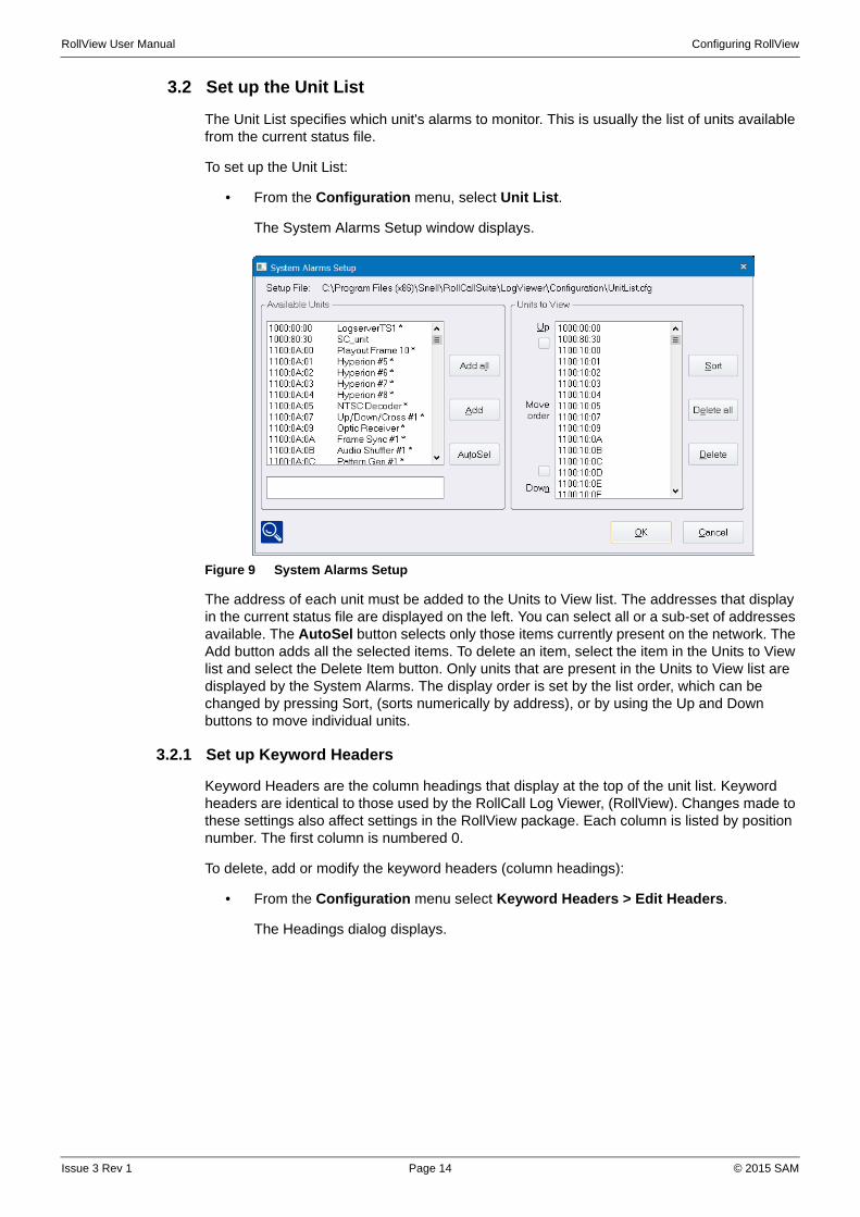
The System Alarms Setup window displays.
Figure 9 System Alarms Setup
The address of each unit must be added to the Units to View list. The addresses that display in the current status file are displayed on the left. You can select all or a sub-set of addresses available. The AutoSel button selects only those items currently present on the network. The Add button adds all the selected items. To delete an item, select the item in the Units to View list and select the Delete Item button. Only units that are present in the Units to View list are displayed by the System Alarms. The display order is set by the list order, which can be changed by pressing Sort, (sorts numerically by address), or by using the Up and Down buttons to move individual units.
3.2.1 Set up Keyword Headers
Keyword Headers are the column headings that display at the top of the unit list. Keyword headers are identical to those used by the RollCall Log Viewer, (RollView). Changes made to these settings also affect settings in the RollView package. Each column is listed by position number. The first column is numbered 0.
To delete, add or modify the keyword headers (column headings):
• From the Configuration menu select Keyword Headers > Edit Headers.
The Headings dialog displays.
Issue 3 Rev 1 Page 14 © 2015 SAM

RollView User Manual Configuring RollView
Figure 10 Keyword Headers
The column is identified by the Header Keyword listed in the current status file. One of the header keywords available in the current status file can be selected using the Browse button. The display line for the unit can be made to change color depending on the words matched in the Warning Keyword and Failure Keyword fields. The Warnings field generates a -Yellow State Failure field generates a -Red State
The Magenta and Cyan parameters can be configured in the same way as Green, Yellow, etc states. They are used to highlight a condition that isn't necessarily a fault; for example, if you had a network switch, you could have all the ports running at 10 Mb be Cyan and all the ports running at 100 Mb as Magenta.
The Exclude Keyword field removes the assigned words from the column and does not display in any state. Multiple word match can be separated with a semicolon (;) character, wild card matching can be assigned using the asterisk (*) character, and the EMPTY keyword can be used to match a blank string. If no keywords are matched to generate any specific state, the state is assigned the Default State. If the checkbox Show only on warning or failure is selected, only items that are either in Warning or Failure state display.
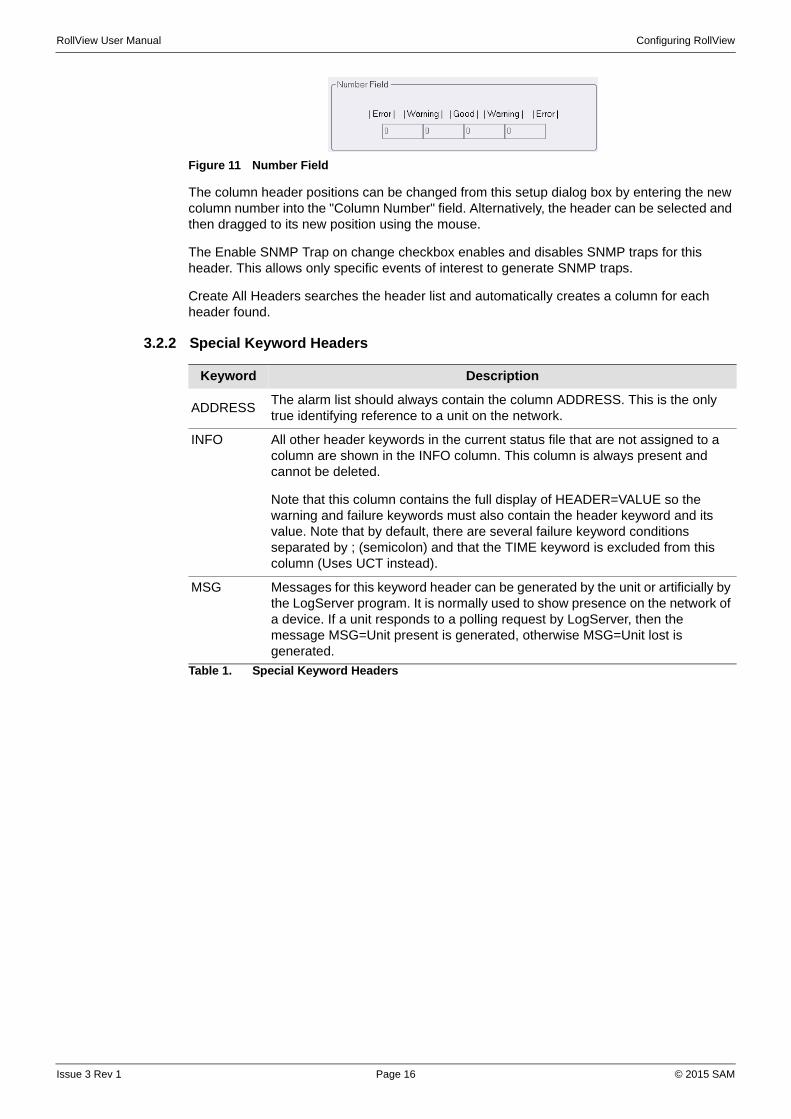
If the column header contains numerical values such as temperature, the state can be set by entering a set of number ranges as a Number Field. To skip a band, enter the same values for its range.
In the example shown in Figure 11:
• Values below 10 generate an error condition.
• Values between 10 and 20 generate a warning.
• Values between 20 and 30 are considered good.
• Values between 30 and 40 generate a warning.
• Values greater than 40 generate an error condition.
Issue 3 Rev 1 Page 15 © 2015 SAM
RollView User Manual Configuring RollView
Figure 11 Number Field
The column header positions can be changed from this setup dialog box by entering the new column number into the "Column Number" field. Alternatively, the header can be selected and then dragged to its new position using the mouse.
The Enable SNMP Trap on change checkbox enables and disables SNMP traps for this header. This allows only specific events of interest to generate SNMP traps.
Create All Headers searches the header list and automatically creates a column for each header found.
3.2.2 Special Keyword Headers
Keyword Description
ADDRESSThe alarm list should always contain the column ADDRESS. This is the only true identifying reference to a unit on the network.
INFO All other header keywords in the current status file that are not assigned to a column are shown in the INFO column. This column is always present and cannot be deleted.
Note that this column contains the full display of HEADER=VALUE so the warning and failure keywords must also contain the header keyword and its value. Note that by default, there are several failure keyword conditions separated by ; (semicolon) and that the TIME keyword is excluded from this column (Uses UCT instead).
MSG Messages for this keyword header can be generated by the unit or artificially by the LogServer program. It is normally used to show presence on the network of a device. If a unit responds to a polling request by LogServer, then the message MSG=Unit present is generated, otherwise MSG=Unit lost is generated.
Table 1. Special Keyword Headers
Issue 3 Rev 1 Page 16 © 2015 SAM

RollView User Manual Configuring RollView
TIME / UCT The LogServer program generates two time keywords for each unit in the current status file. The first is TIME. This is the ASCII version of the time at which the event was logged according to LogServer using its local PC time. However, this TIME field when viewed by a LogViewer on a PC in a different time zone (Wide area network system), indicates incorrect local time. The second keyword is UCT (Universal Co-coordinated Time). This is a numerical value indicating the number of seconds elapsed since 1st January 1970. LogViewers can use this value to generate local or GMT time depending on its own time zone settings.
For example: If a LogServer in San Francisco, California, USA is configured to collect information on a network of RollCall units, it may generate an entry similar to the one below for an IQD1FPG.
NAME=01:IQD1FPG-0,ADDRESS=0000:A0:01,TIME=Thu Apr 30 10:52:41 1998,MSG=Unit present, UCT=893929961, EXTREF=N/A, STD=625, SN=270207,
The time that the event occurred was Thu Apr 30 10:52:41 1998. This is in San Francisco local time. If a monitoring site in Rome, Italy, was configured to view the same status file as generated by the LogServer in San Francisco, then the monitoring site in Rome would also see Thu Apr 30 10:52:41 1998 which is wrong respective to Rome local time. In order to adjust for local time anywhere in the world, the UCT header keyword should be used instead. Each PC should have its Time Zone variable set either by the environmental variable TZ or by setting it within the COMMTROL program. (See COMMTROL: Setting Time Zone). If the Time Zone for San Francisco is set to GMT+8, and Rome to GMT-2, then the LogViewer in San Francisco automatically converts the UCT value (in this example 893929961) into the ASCII string Thu Apr 30 10:52:41 1998. The LogViewer in Rome converts the same UCT value to Thu Apr 30
20:52:41 1998. The LogViewers also have the options of showing the UCT value in GMT time which is identical for both sites (Thu Apr 30 18:52:41 1998 GMT).
Note: Keyword headers can be overridden in the unit list. See “Override Keyword Headers” on page 54.
Keyword Description
Table 1. Special Keyword Headers
Issue 3 Rev 1 Page 17 © 2015 SAM
RollView User Manual Configuring RollView
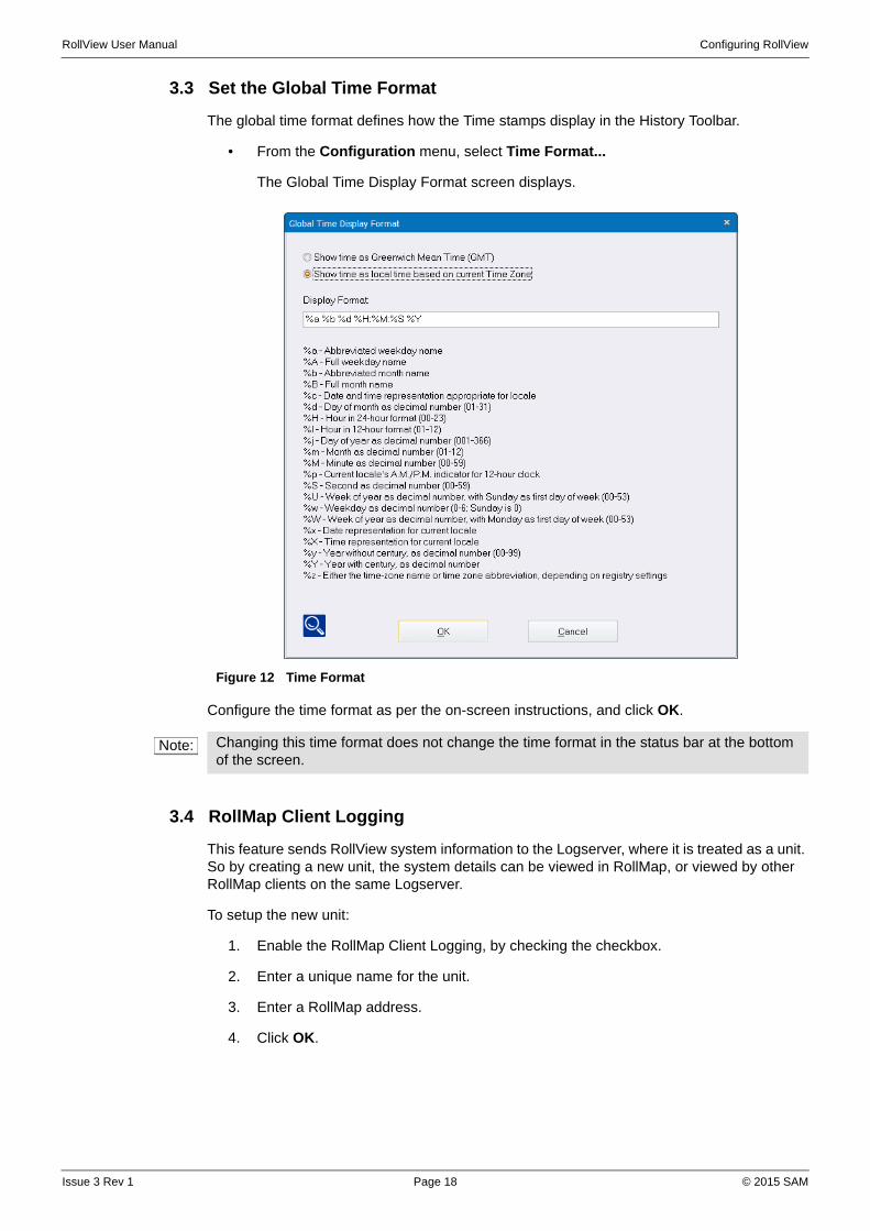
3.3 Set the Global Time Format
The global time format defines how the Time stamps display in the History Toolbar.
• From the Configuration menu, select Time Format...
The Global Time Display Format screen displays.
Configure the time format as per the on-screen instructions, and click OK.
3.4 RollMap Client Logging
This feature sends RollView system information to the Logserver, where it is treated as a unit. So by creating a new unit, the system details can be viewed in RollMap, or viewed by other RollMap clients on the same Logserver.
To setup the new unit:
1. Enable the RollMap Client Logging, by checking the checkbox.
2. Enter a unique name for the unit.
3. Enter a RollMap address.
4. Click OK.
Figure 12 Time Format
Note: Changing this time format does not change the time format in the status bar at the bottom of the screen.
Issue 3 Rev 1 Page 18 © 2015 SAM

RollView User Manual Configuring RollView
Figure 13 RollMap Client Logging
Once the RollMap Client Logging has been enabled, add the new address via the Unit List dialog. Details of the unit can then be displayed in the normal way.
To view the Client Logging details:
• Right-click on the device in the network tree, and select Details... from the menu.
Figure 14 Client Logging Details
Issue 3 Rev 1 Page 19 © 2015 SAM

RollView User Manual Configuring RollView
3.5 Snap Shot IDs
A "Snap shot" of current unit IDs and types can be made so that if any unit is replaced and its type does not match the previous snap shot, it generates a warning or error for that unit's ID and IDNAME field.
To take a snap shot, select the Configuration > Snap Shot IDs > Take Now menu. This deletes all previously stored ID and IDNAME overrides and generates a new override for each unit present.
The current snap shot can be cleared by the Configuration > Snap Shot IDs > Clear All Snap Shots menu.
3.6 Enable SNMP
RollView contains a SNMP extension agent that can generate V1 SNMP traps. The format of the trap is defined by the SNELL-WILCOX-ROLLVIEW.mib. A trap can be configured to occur for any state of each log field. Individual keyword headers can be configured to generate SNMP traps.
To enable SNMP traps:
1. From the Configuration menu, select SNMP.
The SNMP Configuration dialog displays.
2. Select Enable SNMP Traps and then specify the state or states that generate SNMP Traps.
Figure 15 SNMP Configuration
See “SNMP Setup for RollView” on page 81.
3.7 Set up Global Alarm Triggers and Actions
Alarm actions can be configured to generate internal alarms or send external messages when a specified alarm trigger occurs.
To access the alarm actions setup dialog:
• From the Configuration menu, select Alarm Actions.
The Actions dialog displays. If no actions have been previously configured, this screen will be blank.
Issue 3 Rev 1 Page 20 © 2015 SAM

RollView User Manual Configuring RollView
Figure 16 Blank Actions Screen
3.7.1 About Alarm Triggers
Alarm triggers are the specified events that initiate an alarm action. The alarm triggers that can be specified in the alarm window are:
• State Trigger—initiates the specified alarm actions when the state of specified units on the network changes.
• Logserver Lost Trigger—initiates the specified alarm actions when the connection to the log server is lost.
• Control Connection OK Trigger—initiates the specified alarm actions when control connection changes to an OK state.
• Control Connection Warning Trigger—initiates the specified alarm actions when control connection changes to a Warning state.
• Control Connection Lost Trigger—initiates the specified alarm actions when control connection is lost.
• Auto—trigger initiates the specified alarm action when RollView is started.
• Time Based Trigger—trigger initiates an alarm after a defined period of time.
See Configure Alarm Triggers on page 23.
Issue 3 Rev 1 Page 21 © 2015 SAM
RollView User Manual Configuring RollView
3.7.2 About Alarm Actions
Alarm actions are the actions that are carried out when the alarm trigger event occurs. They include:
• Command Line—executes a specified command line.
• Macro—runs a specified macro command.
• Play Sound—plays a specified .wav audio file.
• Send RollTrack—sends a specified RollTrack command.
• Get RollTrack—gets a specified RollTrack command. The way that the action is handled can be configured.
• Send Message—sends an email message.
• Send SNMP—sends an SNMP message (OID set).
• Get SNMP—executes a specified SNMP get.
• Mask Unit—masks specified units.
• UnMask Unit—unmasks specified units.
• Mask Header—masks specified headers of specified units.
• UnMask Header—unmasks specified headers of specified units.
• QC Report—configures a report from an existing history or status tab. Report can be output as HTML, XML or CSV format.
• Logging—allows the History/Current Status tabs logging feature to be configured via actions.
• Ping IP Address—sends a ping command to an IP address and returns a pre-defined result which sets a log field.
• Snell MV Control—control a SAM multiviewer, using the Hydra Open Protocol.
• Streaming Control—control a video stream (play, pause, stop).
See “Configure Alarm Actions” on page 27.
3.7.3 Add an Alarm Trigger
To add an alarm trigger, right-click in the actions list and, from the menu that displays, select one of the following:
• Add Trigger > State Trigger
• Add Trigger > Logserver Lost Trigger
• Add Trigger > Auto
Issue 3 Rev 1 Page 22 © 2015 SAM

RollView User Manual Configuring RollView
Figure 17 Alarm Triggers
Alternatively, click the Add button and, from the list that displays, select an alarm trigger.
Figure 18 Add Trigger
3.7.4 Configure Alarm Triggers
The Logserver Lost Trigger requires no configuration; however, the State Trigger has several configuration options.
Issue 3 Rev 1 Page 23 © 2015 SAM
RollView User Manual Configuring RollView
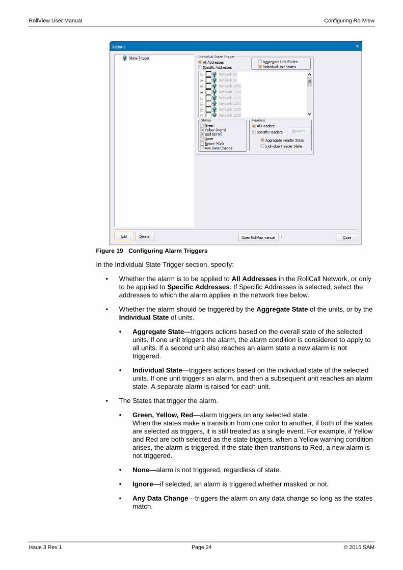
Figure 19 Configuring Alarm Triggers
In the Individual State Trigger section, specify:
• Whether the alarm is to be applied to All Addresses in the RollCall Network, or only to be applied to Specific Addresses. If Specific Addresses is selected, select the addresses to which the alarm applies in the network tree below.
• Whether the alarm should be triggered by the Aggregate State of the units, or by the Individual State of units.
• Aggregate State—triggers actions based on the overall state of the selected units. If one unit triggers the alarm, the alarm condition is considered to apply to all units. If a second unit also reaches an alarm state a new alarm is not triggered.
• Individual State—triggers actions based on the individual state of the selected units. If one unit triggers an alarm, and then a subsequent unit reaches an alarm state. A separate alarm is raised for each unit.
• The States that trigger the alarm.
• Green, Yellow, Red—alarm triggers on any selected state.When the states make a transition from one color to another, if both of the states are selected as triggers, it is still treated as a single event. For example, if Yellow and Red are both selected as the state triggers, when a Yellow warning condition arises, the alarm is triggered, if the state then transitions to Red, a new alarm is not triggered.
• None—alarm is not triggered, regardless of state.
• Ignore—if selected, an alarm is triggered whether masked or not.
• Any Data Change—triggers the alarm on any data change so long as the states match.
Issue 3 Rev 1 Page 24 © 2015 SAM
RollView User Manual Configuring RollView
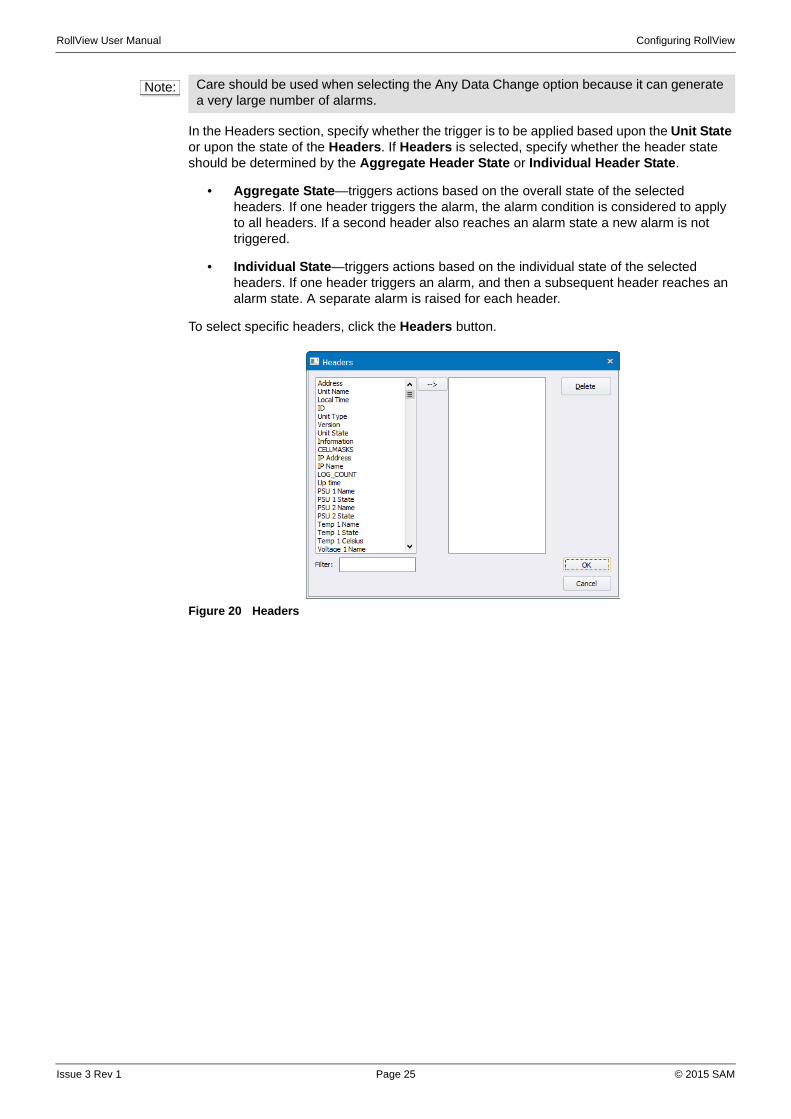
In the Headers section, specify whether the trigger is to be applied based upon the Unit State or upon the state of the Headers. If Headers is selected, specify whether the header state should be determined by the Aggregate Header State or Individual Header State.
• Aggregate State—triggers actions based on the overall state of the selected headers. If one header triggers the alarm, the alarm condition is considered to apply to all headers. If a second header also reaches an alarm state a new alarm is not triggered.
• Individual State—triggers actions based on the individual state of the selected headers. If one header triggers an alarm, and then a subsequent header reaches an alarm state. A separate alarm is raised for each header.
To select specific headers, click the Headers button.
Figure 20 Headers
Note: Care should be used when selecting the Any Data Change option because it can generate a very large number of alarms.
Issue 3 Rev 1 Page 25 © 2015 SAM

RollView User Manual Configuring RollView
3.7.5 Add an Alarm Action
After adding an alarm trigger, to add an action to it, right-click on the trigger and, from the menu that displays, select one of the actions.
Figure 21 Add an Alarm Action
Alternatively, click the Add button and, from the list that displays, select an alarm action.
Multiple alarm actions can be added to the same alarm trigger. For example, both an email message and an SNMP message could be sent to a system administrator in the event of a log server loss.
3.7.6 Alarm Action Operations
Alarm actions can be copied and pasted via the Windows clipboard. The can also be changed into their corresponding opposite action by using Reflect Action (for example, Mask Header becomes UnMask Header).
3.7.7 Trigger Operations
Triggers and all their actions can be duplicated.
3.7.8 Multi Alarm Triggers
Associating a single Alarm action with more than one Alarm Trigger creates a Multi Alarm Trigger type.
To create a Multi trigger, add the first trigger and create an action for it, then add a second trigger at the same level in the tree as the action.
In the example shown in Figure 22 the same Email message has been linked to both a Logserver Lost Trigger and a State Trigger.
Issue 3 Rev 1 Page 26 © 2015 SAM

RollView User Manual Configuring RollView
Figure 22 Multi Alarm Triggers
3.7.9 Configure Alarm Actions
When an alarm action (either global or object) is added its configuration parameters display on the right side of the Actions window.
• Command Line
The Command Line action allows the execution of programs via the command line interpreter.
Figure 23 Command Line
To configure a command line action, enter the command to be run in the text box.
The Command Line action supports several property substitutions, which are listed in the dialog.
Issue 3 Rev 1 Page 27 © 2015 SAM
RollView User Manual Configuring RollView
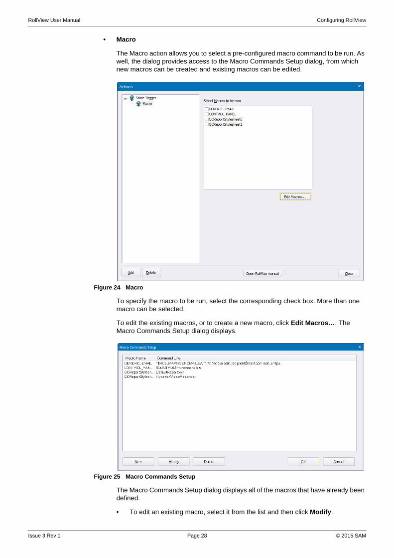
• Macro
The Macro action allows you to select a pre-configured macro command to be run. As well, the dialog provides access to the Macro Commands Setup dialog, from which new macros can be created and existing macros can be edited.
Figure 24 Macro
To specify the macro to be run, select the corresponding check box. More than one macro can be selected.
To edit the existing macros, or to create a new macro, click Edit Macros…. The Macro Commands Setup dialog displays.
Figure 25 Macro Commands Setup
The Macro Commands Setup dialog displays all of the macros that have already been defined.
• To edit an existing macro, select it from the list and then click Modify.
Issue 3 Rev 1 Page 28 © 2015 SAM

RollView User Manual Configuring RollView
• To create a new macro, click New.
In both cases, the Command Macro Setup dialog displays.
Figure 26 Command Macro Setup
In the Macro name field, enter or modify the name of the macro, and in the Command Line field, enter the macro command to be run. The Substitute Search Paths option replaces the path to the macro with the pre-defined RollView search path (if the macro resides in a directory for which a RollView search path has been defined).
• Play Sound
This action plays a specified .WAV file when the alarm trigger occurs.
Figure 27 Play Sound
In the text field, type the path to the .wav file to be played, or click the button to
browse for the file.
• Select Repeat and specify an interval at which the sound is played for the duration of the alarm condition.
Issue 3 Rev 1 Page 29 © 2015 SAM
RollView User Manual Configuring RollView
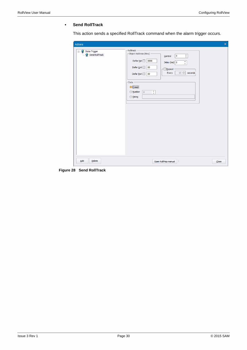
• Send RollTrack
This action sends a specified RollTrack command when the alarm trigger occurs.
Figure 28 Send RollTrack
Issue 3 Rev 1 Page 30 © 2015 SAM

RollView User Manual Configuring RollView
• Get RollTrack
This action gets a specified RollTrack command when the alarm trigger occurs. The way that the action is handled depends on the configuration of this screen.
Figure 29 Get RollTrack
To handle the state of a unit, define the values for the OK, Warning, and Fail States. To display the results in a meaningful format, process the received data, converting to an actual value with the appropriate unit, for example, mV, °C.
Use the Test button to apply values to the definition and check for the expected results.
Define the address for the unit to which Get RollTrack is sent. Also define the Log Header address.
The log unit and log header fields are used to specify the destination of the Get action. It will populate the field on the specified unit with the processed data. This can be either an additional field on an already existing live unit or on a "virtual" unit by choosing an unused address.
Issue 3 Rev 1 Page 31 © 2015 SAM

RollView User Manual Configuring RollView
• Send Message
This action sends an email to a specified recipient or recipients when the alarm trigger occurs. Before emails can be sent as alarm actions, at least one email profile must be configured. See “Configure Email Messages” on page 44.
Figure 30 Send Message
To configure a Send Message action:
• In the Send To: field, specify a recipient.
• In the Message text box, create the message body. You can include any log field header into this email message and RollView inserts the correct data.
For example: To receive an email that says the following:
"Unit: Hyperion 1, Type: IQSDA02, at Address: 1100:10:01, has triggered an alarm at Time=15:13:56, 13 November 2015."
You would insert the following into the Message section:
"Unit: #NAME#, Type: #IDNAME#, at Address: #ADDRESS#, has triggered an alarm at Time=#TIME#, #UCT#."
Issue 3 Rev 1 Page 32 © 2015 SAM

RollView User Manual Configuring RollView
• Send SNMP
This action sends a parameter value set via SNMP when the alarm trigger occurs.
Figure 31 Send SNMP
In this window, enter the details of the SNMP message to be sent. Dynamic data insertion can be used on the Agent Address, OID and community fields. See “Dynamic Data Insertion” on page 98.
Issue 3 Rev 1 Page 33 © 2015 SAM

RollView User Manual Configuring RollView
• Get SNMP
This action gets a value via SNMP when the alarm trigger occurs. The log unit and header destination for the value can be specified.
Figure 32 Get SNMP
In this window, enter the details of the SNMP data to be requested. Dynamic data insertion can be used on the Agent Address, OID and community fields. See “Dynamic Data Insertion” on page 98.
The results can be processed into states by entering lists of possible values to be matched separated by semi-colons.
The virtual unit and log field header that the result is sent to can also be configured. If no specific Log Header is given the OID is used.
Issue 3 Rev 1 Page 34 © 2015 SAM

RollView User Manual Configuring RollView
• Mask Unit
This action masks a specified selection of unit(s) with the option of only masking until they become green.
Figure 33 Mask Unit
In this window select from the tree which unit are to be masked, there is also the option to mask until green.
By right-clicking on the Mask Unit action in the actions tree you can use Reflect Action to convert a Mask Unit Action into an UnMask Unit action.
Figure 34 Actions - Reflect Action
Issue 3 Rev 1 Page 35 © 2015 SAM

RollView User Manual Configuring RollView
• Unmask Unit
This action unmasks a specified selection of unit(s) with the option of only masking until they become green.
Figure 35 Unmask Unit
In this window select from the tree which unit are to be unmasked.
By right-clicking on the UnMask Unit action in the actions tree you can use Reflect Action to convert a UnMask Unit Action into an Mask Unit action.
Issue 3 Rev 1 Page 36 © 2015 SAM

RollView User Manual Configuring RollView
• Mask Header
This action masks a specified selection of header(s) for a selection of unit(s) with the option of only masking until they become green.
Figure 36 Mask Header
In this window select from the tree which headers of which units are to be masked, there is also the option to mask until green.
By right-clicking on the Mask Header Unit action in the actions tree you can use Reflect Action to convert a Mask Header Action into an UnMask Header Unit action.
Issue 3 Rev 1 Page 37 © 2015 SAM
RollView User Manual Configuring RollView
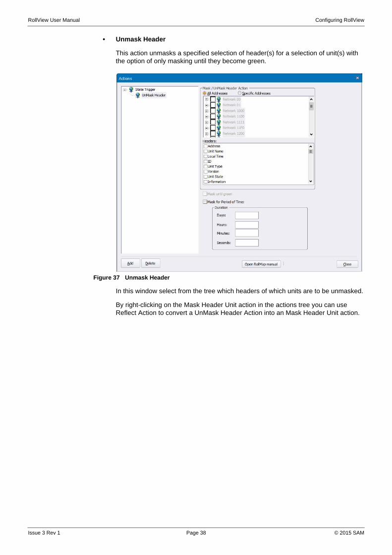
• Unmask Header
This action unmasks a specified selection of header(s) for a selection of unit(s) with the option of only masking until they become green.
Figure 37 Unmask Header
In this window select from the tree which headers of which units are to be unmasked.
By right-clicking on the Mask Header Unit action in the actions tree you can use Reflect Action to convert a UnMask Header Action into an Mask Header Unit action.
Issue 3 Rev 1 Page 38 © 2015 SAM

RollView User Manual Configuring RollView
• QC Report
Figure 38 QC Report
This action allows an HTML, XML, or CSV file to be created from the data of any of the status tabs (current status or history tabs) in the form of a report. Filtering and styling features are provided for the report.
Specify a report title, and the source of the data for the report.
Define which addresses are to be used in the report, either All, or Specific Addresses selected by checking the appropriate checkboxes in the Filtering window.
Apply any rules, as required. See Rules Engine on page 91.
Define the output format and filename for the report.
Click on the Properties button next to the report name, to display the Report Properties window. From here the styling of the report is set.
Issue 3 Rev 1 Page 39 © 2015 SAM

RollView User Manual Configuring RollView
Figure 39 Report Properties
Select the theme. This is a style-sheet used to create the report. Additional style-sheets can be referenced from [Install Directory]/Configuration/Configuration.cfg, and then selected from this drop-down box.
Add a subtitle and description, as required.
The Highlighting section defines the colors to be used for highlighting the report rows containing the specified keywords.
A custom logo can be added to the output report. Click on the browse button ( ) and navigate to the folder containing the logo.
User-defined arguments can be passed to the style-sheet. For example, in Figure 39 a parameter “custom_arg” is defined with a string value. The theme “Default Layout” is rendered using the style-sheet [Install Directory]/Configuration/DefaultReport.xslt. This file can be edited using a text editor, to make use of the custom parameter.
Click on the Notifications button to define an action to take place after the report is generated:
Figure 40 Notification Settings
Select from None, Alert with a popup message box, or Open the report using a web browser.
Reports are processed as a background task, and may take some time to generate. While processing a “QC” indicator displays on the right-hand side of the status bar.
Issue 3 Rev 1 Page 40 © 2015 SAM

RollView User Manual Configuring RollView
• Logging
Allows the History/Current Status tabs logging feature in RollView to be configured via actions.
Figure 41 Logging
Select a source from the History or Status tab drop-down list.
Determine the action by selecting the appropriate radio button.
Issue 3 Rev 1 Page 41 © 2015 SAM

RollView User Manual Configuring RollView
• Ping IP Address
Figure 42 Ping IP Address
Set the IP address of the unit to send the ping command to.
Define additional text for the success and failure results, if required.
Set the address for the virtual log unit. Check the Write to Log checkbox if the result is to be sent to the Log Server so it is visible to other clients.
Issue 3 Rev 1 Page 42 © 2015 SAM
RollView User Manual Configuring RollView
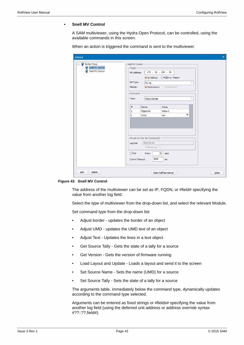
• Snell MV Control
A SAM multiviewer, using the Hydra Open Protocol, can be controlled, using the available commands in this screen.
When an action is triggered the command is sent to the multiviewer.
Figure 43 Snell MV Control
The address of the multiviewer can be set as IP, FQDN, or #field# specifying the value from another log field.
Select the type of multiviewer from the drop-down list, and select the relevant Module.
Set command type from the drop-down list:
• Adjust border - updates the border of an object
• Adjust UMD - updates the UMD text of an object
• Adjust Text - Updates the lines in a text object
• Get Source Tally - Gets the state of a tally for a source
• Get Version - Gets the version of firmware running
• Load Layout and Update - Loads a layout and send it to the screen
• Set Source Name - Sets the name (UMD) for a source
• Set Source Tally - Sets the state of a tally for a source
The arguments table, immediately below the command type, dynamically updates according to the command type selected.
Arguments can be entered as fixed strings or #fields# specifying the value from another log field (using the deferred unit address or address override syntax #??::??,field#).
Issue 3 Rev 1 Page 43 © 2015 SAM

RollView User Manual Configuring RollView
The result of the GetVersion and GetSourceTally commands can be set on the virtual log unit.
• Get version creates fields MV_FIRMWARE_VERSION and MV_OS_VERSION
• Get source tally creates MV_TALLY_SOFT1_SRC_[N], MV_TALLY_SOFT2_SRC_[N] and MV_TALLY_HARDWARE_SRC_[N] where [N] is a numeric source id.
Check the write to log server checkbox to send the virtual unit (and headers) to log server, so they are viewable in other clients.
Poll causes the action to be repeated (when the action is placed on an auto trigger). Set a poll interval time accordingly
Comms timeout specifies the network timeout communicating with the MV. Set the timeout in ms.
3.8 Configure Email Messages
Before any emails can be sent as alarm actions:
1. A transport profile, which specifies the method by which emails are to be sent, must be created. See “Create a Transport Profile” on page 45.
By default RollView includes the Open Source SMTP tool blat.exe for sending mail messages. The arguments for this tool can be configured in the Configuration > Message Configuration > Transports dialog. For full details, refer to the online documentation at http://www.blat.net/syntax/syntax.html
2. A message profile, which specifies the email recipients and structure, must be created. See “Create a Message Profile” on page 46.
3. A Send Message alarm action must be created.
To access the email configuration dialogs:
• From the Configuration menu, select Message Configuration.
The Profiles dialog displays.
Figure 44 Profiles
Issue 3 Rev 1 Page 44 © 2015 SAM
RollView User Manual Configuring RollView
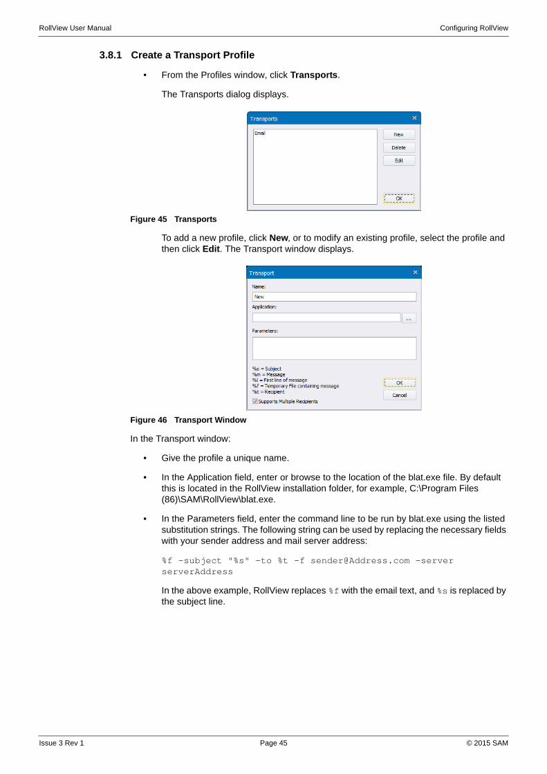
3.8.1 Create a Transport Profile
• From the Profiles window, click Transports.
The Transports dialog displays.
Figure 45 Transports
To add a new profile, click New, or to modify an existing profile, select the profile and then click Edit. The Transport window displays.
Figure 46 Transport Window
In the Transport window:
• Give the profile a unique name.
• In the Application field, enter or browse to the location of the blat.exe file. By default this is located in the RollView installation folder, for example, C:\Program Files (86)\SAM\RollView\blat.exe.
• In the Parameters field, enter the command line to be run by blat.exe using the listed substitution strings. The following string can be used by replacing the necessary fields with your sender address and mail server address:
%f -subject "%s" -to %t -f [email protected] -server serverAddress
In the above example, RollView replaces %f with the email text, and %s is replaced by the subject line.
Issue 3 Rev 1 Page 45 © 2015 SAM

RollView User Manual Configuring RollView
Figure 47 Transport Details
• Click OK to close the Window, and then click OK again.
3.8.2 Create a Message Profile
To create a message profile that specifies the recipients and emails options. From the Profiles window, click New, or to modify an existing profile, select the profile and then click Edit. The Recipients window displays.
Figure 48 Recipients
• Give the profile a unique name.
• Click Add, and in the window that displays, enter the name of a recipient. Then, select the transport type (which was set up in the previous section) and click OK. If required, multiple email addresses can be added at this stage.
Figure 49 Add Recipient
Issue 3 Rev 1 Page 46 © 2015 SAM

RollView User Manual Configuring RollView
The Options sections at the bottom of the window specify whether emails should be sent immediately or joined into larger messages. If you choose to join messages, RollView waits for a specified period to see if any subsequent alarms follow. If this does occur, the details of both alarms are sent in one message.
A scenario in which this is useful would be if a modular frame was turned off. If messages are sent immediately, one email would be sent to alert of the loss of the Gateway card, a second email would be sent to alert of the loss of the card in slot 1, a third email to alert of the loss of the card in slot two, and so on. By joining messages, these alerts would be combined into a single message.
The parameters for joining messages are:
Initial Delay—specifies how long the system waits after receiving the first alert before it assumes that no further alerts are coming and sends the message.
Max Idle—specifies how long the system waits after receiving another alert before it assumes no more are coming.
Max Time—specifies the maximum amount of time from the first alert to the last. When this time limit is reached, the system sends a message, even if more may be coming.
Max Messages—specifies the maximum number of messages that the system queues before sending.
• Click the Contents button to open the Message Text window, in which the email subject line, header text and footer text can be specified.
Figure 50 Message Text Window
After completing this configuration, email alarm actions can be set up.
Issue 3 Rev 1 Page 47 © 2015 SAM

RollView User Manual Configuring RollView
3.9 Set up Search Paths
RollView can use search path macros to locate the full path name of a file.
To access the Search Path Setup dialog:
• From the Configuration menu, select Search Paths > Edit.
Figure 51 Search Path Setup
A macro can be set up so that it can be used in any path field within the object properties.
For example:
Macro definition: NOTEPAD=C:\Windows\notepad.exe
Use of macro: when used in a global Action LogServer Lost trigger:<NOTEPAD>
At run time, the command line expands to: C:\Windows\notepad.exe and launches Notepad when connection to LogServer is lost.
A macro may contain only ONE other macro definition.
For example:
Macro definition: ROLLVIEW=C:\RollView
then define a new macro: TEST=$ROLLVIEW$\Test
Expanding the macro $TEST$ becomes C:\RollView\Test
A predefined set of macros is provided for use with the current RollView component libraries.
If the Use Search Paths Automatically option is enabled and a path field is entered by browsing, the path is scanned and may be reduced by the use of path macro substitutions. A manual "Paths" button is also available next to most fields that support search path substitutions.
Issue 3 Rev 1 Page 48 © 2015 SAM

RollView User Manual Configuring RollView
Figure 52 Search Paths Automatically
3.10 Configure Shortcut Links
The links menu provides a set of shortcut links that can be configured if desired. After configuring the links menu, the links menu shown below can be used.
Figure 53 Shortcut Links
To add the links option, add the following parameters to the Configuration.cfg file, which is located in the Configuration folder of the installation directory. By default, the location of this file is:
C:\Program Files\SAM\RollView\Configuration\Configuration.cfg.
Note: RollView must be closed before opening the configuration file, and not restarted until the changes in the files have been saved.
Issue 3 Rev 1 Page 49 © 2015 SAM
RollView User Manual Configuring RollView
The parameters to add are:
[AlarmViewRightClickAllUnits] Item0=Launch RollCall Control,<CONTROL_PANEL>
[AlarmViewRightClickPortZero] Item0=Launch RollCall Control to enclosing gateway,$CONTROL$ -runonce -u %N:%U:00
[AlarmViewRightClickPortNonZero] Item0=Example item for enclosures only
3.11 Other Configuration Options
The options described in this section set several other preferences that allow you to customize RollView.
• Fonts—specifies the font used in the System Alarms window.
To change the font used in the System Alarms display, from the Configuration menu, select Fonts. A font selection dialog displays, from which the font can be selected.
• Colors—specifies the state and system colors used in the System Alarms window.
To change the state and system colors, from the Configuration menu, select Colors.
To change the color for an item, select the item from the drop-down list and click Change. A color selection palette box displays. Any custom or predefined color can be selected. The system can store up to 16 custom colors.
To reset any field, click Default.
• Highlights—configures the highlight behavior displayed when a field in the System Alarms window changes.
When a field changes, it can be highlighted using a "Highlight Color". To change the highlights settings, from the Configuration menu, select Highlights.
The color can be set from the Color menu.
The highlight duration can be set from 1 to 32000 seconds. If the Manual reset checkbox is selected, the highlight remains on the field. To manually reset the highlight, from the View menu, select Highlight Changes > Clear All or Clear Line.
• Time Format—configures the time format used by RollView.
To specify the time format, from the Configuration menu, select Time Format.
Specify whether the time should be displayed as Greenwich Mean Time or Local Time, and using the parameters shown in the dialog, construct the desired time display format.
The time and date are displayed at the bottom of the RollView main window, and also displayed in the System Alarm window under the "Network Time" heading.
• Auto Discovery—enables Auto Discovery mode. See Auto Discovery on page 65.
• Clear Cache—deletes all files in the RollView cache directory.
Issue 3 Rev 1 Page 50 © 2015 SAM

RollView User Manual System Alarms Window
4. System Alarms Window
4.1 Description
The System Alarms Window is a table made from units in the system and their alarm headers. Each entry in the table is a trigger event for an alarm.
Fig 54. System Alarms Window Configuration
4.2 Connect to Units
RollView can connect to the RollCall Control Panel and open a specified unit's template; or, if the unit has an IP Address log field, connect to its Web-based management interface.
• To open a unit in the RollCall Control panel, right-click on the unit in the System Alarms window and from the menu, select Connect to RollCall Panel. The unit's template displays in the RollCall Control Panel.
• To open a unit's Web-based management interface (if the unit has an IP Address log field), right-click on the unit in the System Alarms window and from the menu, select Connect to URL. The unit's management interface displays.
4.3 Mask Units
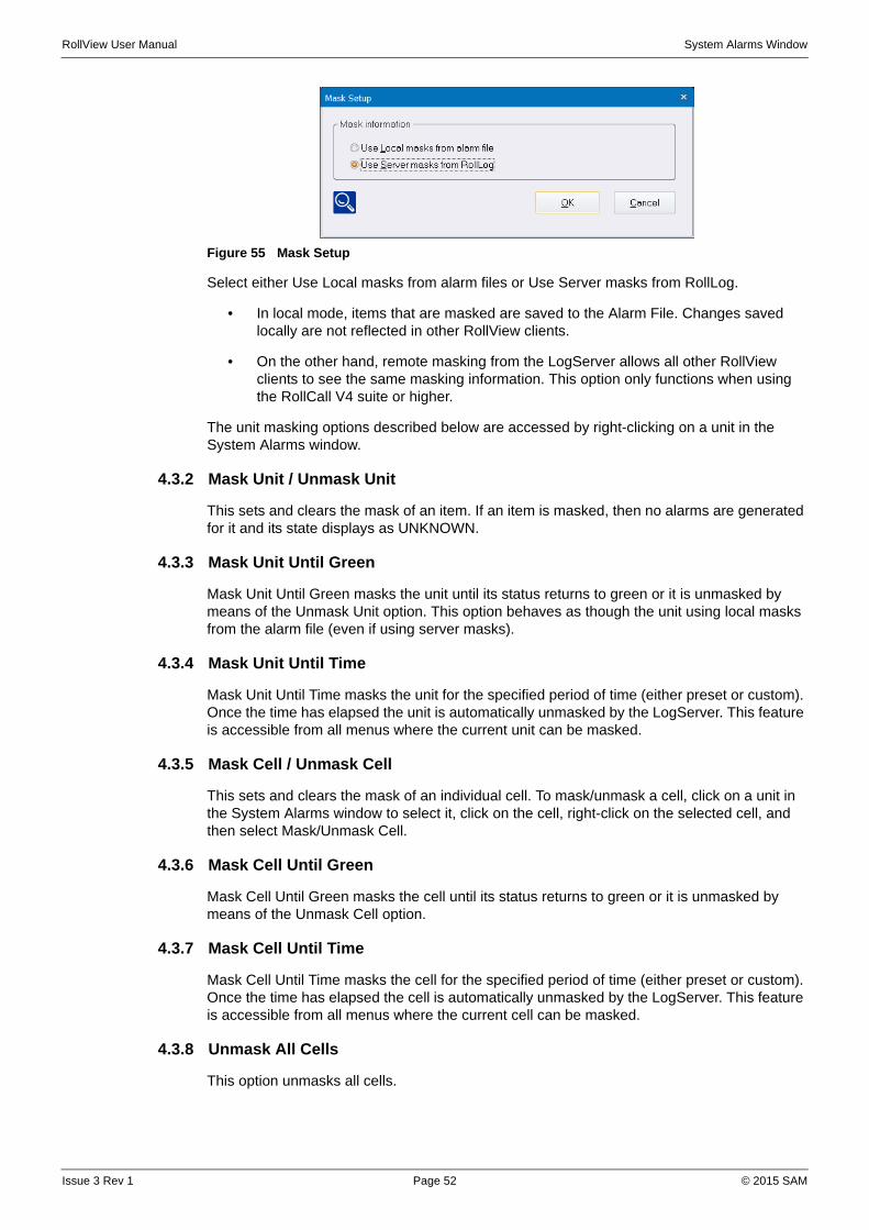
4.3.1 Mask Setup
The Mask Setup option specifies whether item masks are saved locally, or received from a server.
To change the Mask Setup:
• From the Configuration menu, select Mask Setup.
The Mask Setup dialog displays.
System Alarms Window
Issue 3 Rev 1 Page 51 © 2015 SAM
RollView User Manual System Alarms Window
Figure 55 Mask Setup
Select either Use Local masks from alarm files or Use Server masks from RollLog.
• In local mode, items that are masked are saved to the Alarm File. Changes saved locally are not reflected in other RollView clients.
• On the other hand, remote masking from the LogServer allows all other RollView clients to see the same masking information. This option only functions when using the RollCall V4 suite or higher.
The unit masking options described below are accessed by right-clicking on a unit in the System Alarms window.
4.3.2 Mask Unit / Unmask Unit
This sets and clears the mask of an item. If an item is masked, then no alarms are generated for it and its state displays as UNKNOWN.
4.3.3 Mask Unit Until Green
Mask Unit Until Green masks the unit until its status returns to green or it is unmasked by means of the Unmask Unit option. This option behaves as though the unit using local masks from the alarm file (even if using server masks).
4.3.4 Mask Unit Until Time
Mask Unit Until Time masks the unit for the specified period of time (either preset or custom). Once the time has elapsed the unit is automatically unmasked by the LogServer. This feature is accessible from all menus where the current unit can be masked.
4.3.5 Mask Cell / Unmask Cell
This sets and clears the mask of an individual cell. To mask/unmask a cell, click on a unit in the System Alarms window to select it, click on the cell, right-click on the selected cell, and then select Mask/Unmask Cell.
4.3.6 Mask Cell Until Green
Mask Cell Until Green masks the cell until its status returns to green or it is unmasked by means of the Unmask Cell option.
4.3.7 Mask Cell Until Time
Mask Cell Until Time masks the cell for the specified period of time (either preset or custom). Once the time has elapsed the cell is automatically unmasked by the LogServer. This feature is accessible from all menus where the current cell can be masked.
4.3.8 Unmask All Cells
This option unmasks all cells.
Issue 3 Rev 1 Page 52 © 2015 SAM

RollView User Manual System Alarms Window
4.4 Query the State of a Unit
To view the details of any warnings or errors with a unit, right-click on the unit in the System Alarms window and select Query State. A dialog displays indicating warnings or errors currently being generated by the unit.
Figure 56 Query State
4.5 Change View Options
There are eight tool/status bars available on the System Alarm window. The General Toolbar displays just beneath the menus. The Status bar contains six boxes with colored icons, displaying the total number units in each state and the total number of units. Their description can be viewed by placing the cursor over the boxes and a tool tip will appear. The green bar at the right of the status bar is an activity indicator only. Full Screen - expands the System Alarm window to fill the monitor screen. Show text on Tool bars - places the function name of a tool icon under the icon Hide When Minimized - hides the RollView icon in the bottom right system tray.
Figure 57 View Options
4.5.1 Aggregate State
The display can be set to show the total aggregate of a unit based on the states of all its triggers. This shows the unit as a single colored line. Turning off the aggregate state displays each trigger field as its actual state color.
4.5.2 Highlight Changes
When "Highlights" are enabled, recent changes are shown in a different color. The duration and reset mode can be changed in the Configuration > Highlights menu.
4.5.3 Auto-arrange Column Widths
Selecting this option automatically adjusts the column widths to fit all data.
Issue 3 Rev 1 Page 53 © 2015 SAM

RollView User Manual System Alarms Window
4.5.4 Show Error State in Network Tree
Selecting this option displays unit states in the network tree by placing a dot corresponding to the states color on the object icons.
4.6 Override Keyword Headers
A single cell of the System Alarms window can be selected by first selecting the row with the left mouse button, then clicking on a cell within the selected row. This highlights the cell with a dotted rectangle. Right-click in a selected cell and from the menu that displays, select Override Keyword Headers.
This cell's state can be given a different set of keywords, similar to the overall keywords for the whole column. If an override exists for that cell, its background color is set by the "Header Override Color" in the Color setup dialog box.
Figure 58 Override Keyword Headers
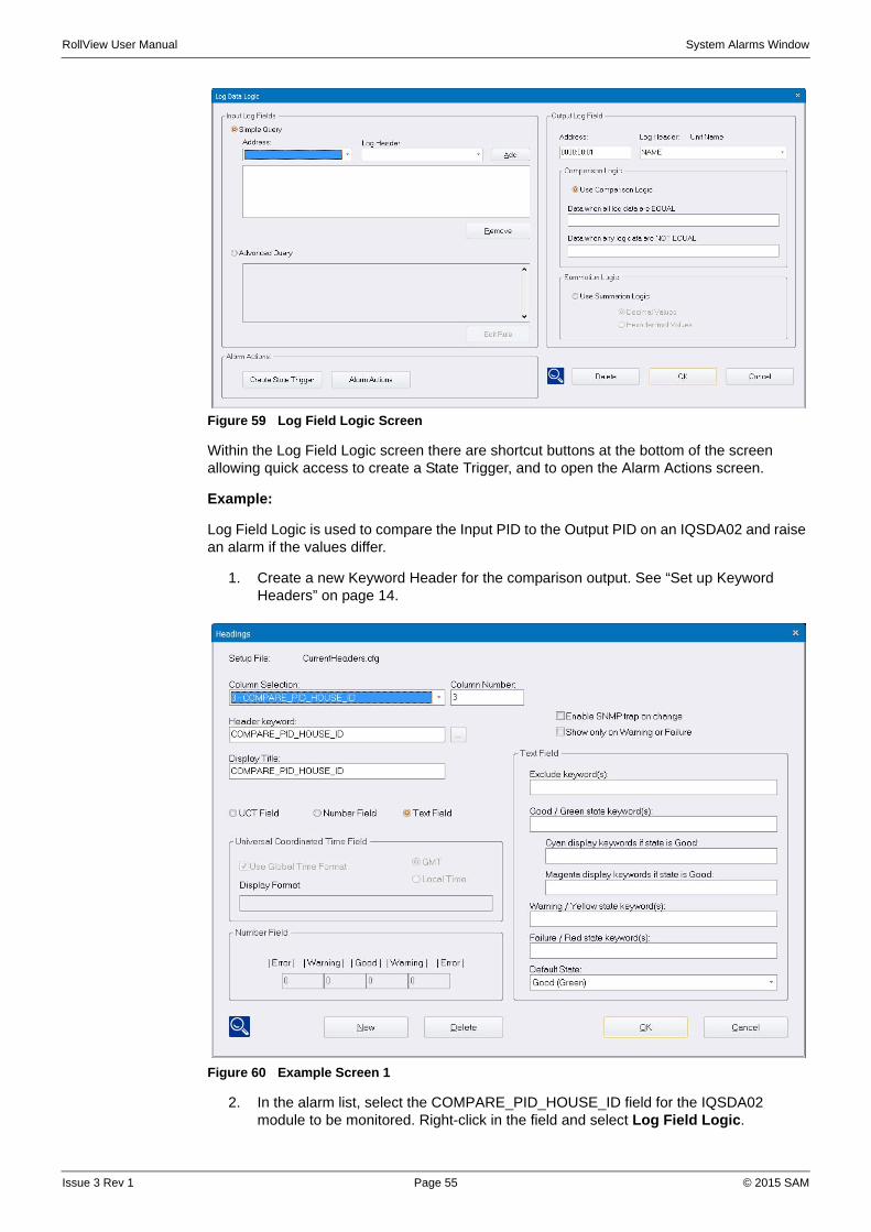
4.7 Log Field Logic
Log Field Logic outputs a value to a Log Field that depends on the value of two or more input Log Fields. Input Fields can be added or logically compared.
To access the Log Field Logic dialog:
• Right-click on a log field in the System Alarms window and select Log Field Logic from the menu.
Issue 3 Rev 1 Page 54 © 2015 SAM
RollView User Manual System Alarms Window
Figure 59 Log Field Logic Screen
Within the Log Field Logic screen there are shortcut buttons at the bottom of the screen allowing quick access to create a State Trigger, and to open the Alarm Actions screen.
Example:
Log Field Logic is used to compare the Input PID to the Output PID on an IQSDA02 and raise an alarm if the values differ.
1. Create a new Keyword Header for the comparison output. See “Set up Keyword Headers” on page 14.
Figure 60 Example Screen 1
2. In the alarm list, select the COMPARE_PID_HOUSE_ID field for the IQSDA02 module to be monitored. Right-click in the field and select Log Field Logic.
Issue 3 Rev 1 Page 55 © 2015 SAM

RollView User Manual System Alarms Window
3. In the Log Field Logic dialog, select the Address and Log Header of the Input PID, then click Add.
Figure 61 Example Screen 2
4. Select the Address and Log Header of the Output PID, then click Add.
Figure 62 Example Screen 3
5. In the Comparison Logic section, enter the text to be displayed when the log data is equal and when the log data is not equal.
Issue 3 Rev 1 Page 56 © 2015 SAM
RollView User Manual System Alarms Window
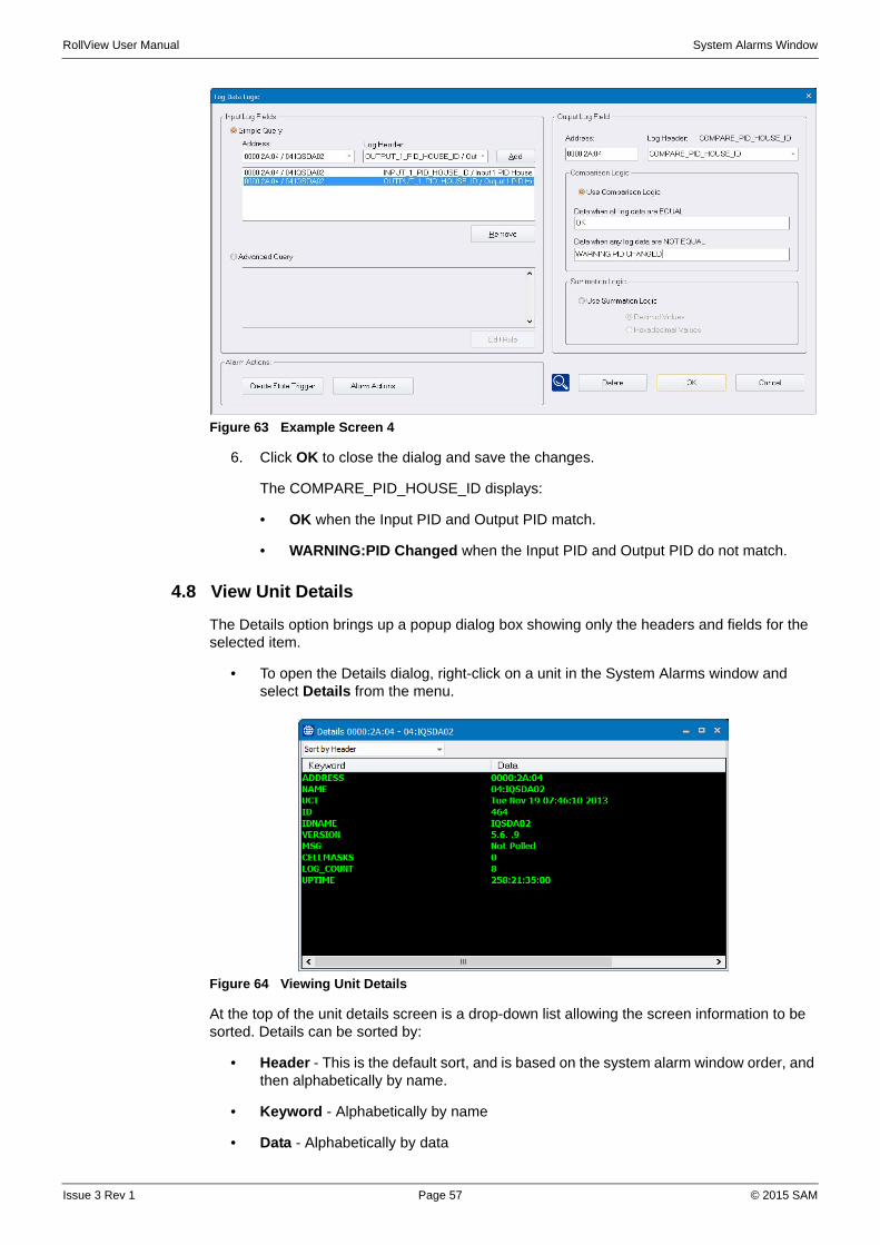
Figure 63 Example Screen 4
6. Click OK to close the dialog and save the changes.
The COMPARE_PID_HOUSE_ID displays:
• OK when the Input PID and Output PID match.
• WARNING:PID Changed when the Input PID and Output PID do not match.
4.8 View Unit Details
The Details option brings up a popup dialog box showing only the headers and fields for the selected item.
• To open the Details dialog, right-click on a unit in the System Alarms window and select Details from the menu.
Figure 64 Viewing Unit Details
At the top of the unit details screen is a drop-down list allowing the screen information to be sorted. Details can be sorted by:
• Header - This is the default sort, and is based on the system alarm window order, and then alphabetically by name.
• Keyword - Alphabetically by name
• Data - Alphabetically by data
Issue 3 Rev 1 Page 57 © 2015 SAM

RollView User Manual System Alarms Window
• Status - Errors are reported first, followed by warnings, followed by everything else
• Mask - Masked cells followed by unmasked cells
4.9 Printing
The current state of the System Alarms window can be printed.
4.9.1 Page Setup Options
To change the page setup options:
• From the File menu, select Page Setup.
The Page Setup for Printing dialog displays.
Figure 65 Page Setup
There are two print setup options available in this dialog:
• Always resize horizontally to fit paper—configures RollView to print all headers across a single page, re-scaling if necessary. If this option is not selected, only the fields that fit on the first page using the current font are printed.
• Use black and white only—produces a clearer monochrome gray scale output on a black and white printer.
4.9.2 Printer Setup Options
To change the printer setup option:
• From the File menu, select Print Setup.
The standard printer setup dialog for your printer displays. The options that can be specified here depend on the printer.
4.9.3 Print Preview
To view a preview of the print job before printing:
• From the File menu, select Print Preview.
This displays the exact layout of the page to be printed.
4.9.4 Print
To print the contents of the System Alarms window:
• From the File menu, select Print.
The printer setup dialog displays.
• Specify any required print options and then click OK to continue.
Issue 3 Rev 1 Page 58 © 2015 SAM

RollView User Manual System Alarms Window
4.10 User Alarms
User Alarm documents can be created to manage smaller numbers of units. This can be a subset of the units available from the System Alarms window. The Alarm window is split into two windows. The left window is the Active state window. This shows the current status of user-selected units. The right hand window is the masked window. This shows the status of units that you have masked, or have already noticed and wish to ignore. Using a combination of viewing masks, you can be informed of changes quickly and accurately.
File Open, Close, Save and Save As are standard file options for an alarm document. Settings for each User Alarm document can be saved with the extension .ALM. Edit options Cut, Copy and Paste from the System Alarms window can be used to aid editing of the alarm document.
Configuration options are the same as those available in the System Alarms window.
4.10.1 Set up an Alarm Document
To create a new User Alarm document:
• From the File menu, select New.
The New File dialog displays.
Figure 66 New Alarm Document
• Select User Alarms and then click OK.
The default list of units and column headings reflect those available from the System Alarms window.
4.10.2 Unit State
The left-hand window indicates the active state of the units and the right hand window indicates the status of masked units. Each window has a viewing mask for each of the states. Click on the right hand mouse to bring down a context menu. The drop-down menu has options to view Errors, Warnings, Unknowns and OK states.
Figure 67 Unit State
Issue 3 Rev 1 Page 59 © 2015 SAM
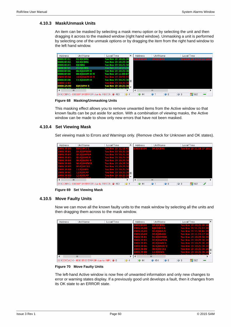
RollView User Manual System Alarms Window
4.10.3 Mask/Unmask Units
An item can be masked by selecting a mask menu option or by selecting the unit and then dragging it across to the masked window (right hand window). Unmasking a unit is performed by selecting one of the unmask options or by dragging the item from the right hand window to the left hand window.
Figure 68 Masking/Unmasking Units
This masking effect allows you to remove unwanted items from the Active window so that known faults can be put aside for action. With a combination of viewing masks, the Active window can be made to show only new errors that have not been masked.
4.10.4 Set Viewing Mask
Set viewing mask to Errors and Warnings only. (Remove check for Unknown and OK states).
Figure 69 Set Viewing Mask
4.10.5 Move Faulty Units
Now we can move all the known faulty units to the mask window by selecting all the units and then dragging them across to the mask window.
Figure 70 Move Faulty Units
The left-hand Active window is now free of unwanted information and only new changes to error or warning states display. If a previously good unit develops a fault, then it changes from its OK state to an ERROR state.
Issue 3 Rev 1 Page 60 © 2015 SAM
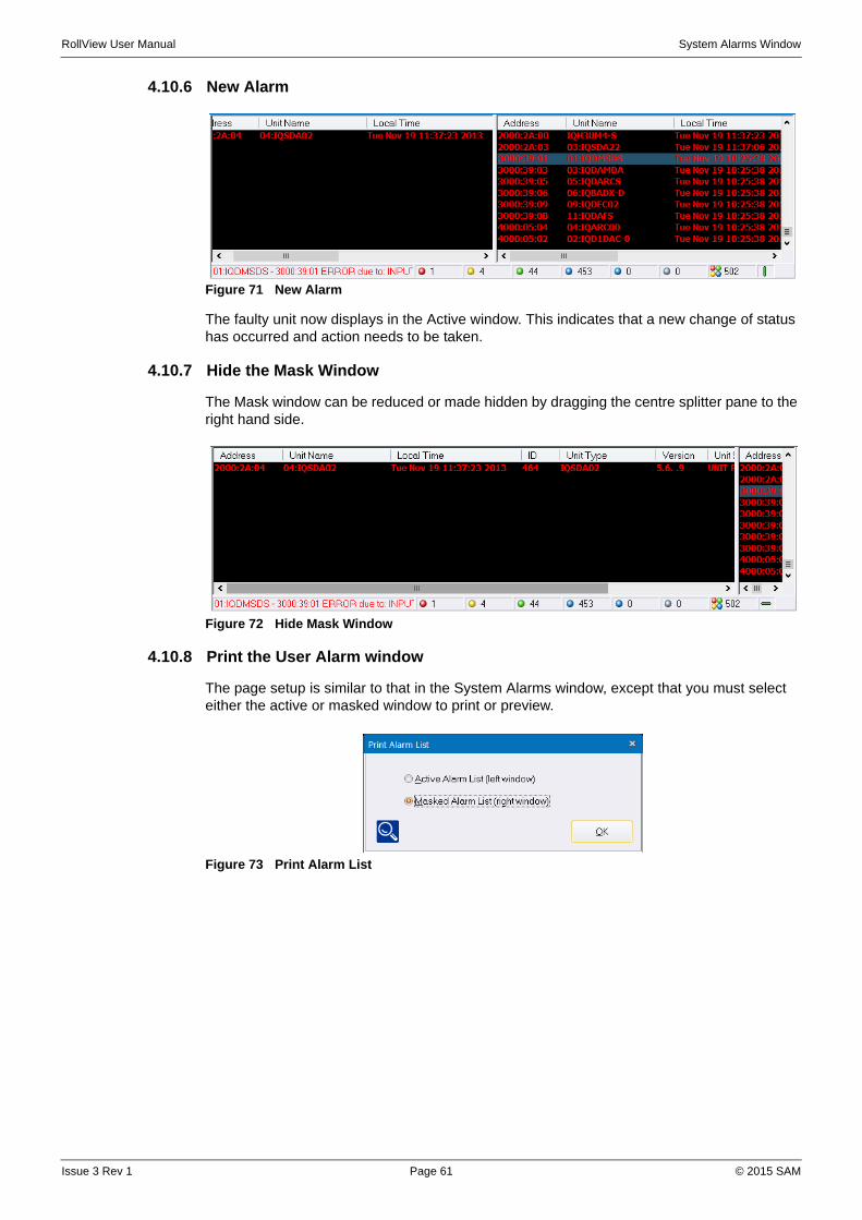
RollView User Manual System Alarms Window
4.10.6 New Alarm
Figure 71 New Alarm
The faulty unit now displays in the Active window. This indicates that a new change of status has occurred and action needs to be taken.
4.10.7 Hide the Mask Window
The Mask window can be reduced or made hidden by dragging the centre splitter pane to the right hand side.
Figure 72 Hide Mask Window
4.10.8 Print the User Alarm window
The page setup is similar to that in the System Alarms window, except that you must select either the active or masked window to print or preview.
Figure 73 Print Alarm List
Issue 3 Rev 1 Page 61 © 2015 SAM

RollView User Manual System Alarms Window
4.11 Configure Headers
Any of the column headers available from the System Alarms window can be added to the User Alarms windows. Columns can also be deleted if not required.
A header can be selected and dragged to a new position with the mouse.
The Edit menu provides access to Copy, Paste and Select All options. Unit entries can be copied to the clipboard for use in the User Alarm window. Items in this window can be dragged onto the User Alarm windows for faster editing operations.
Right-click on the header bar in the System Alarms window to display a context menu and select the required option.
Figure 74 Headers Menu
The User Alarms window has a similar menu, but with a subset of these features.
4.11.1 Select Columns
Selecting this option brings up a dialog box with all the available column headers on the left, and the currently used headers, in the order that they display in the system alarms screen, on the right.
Figure 75 Select Columns
To add a new header:
1. Select a header name from the left column, and click on
2. The new header is added to the bottom of the list. Use the Move Up and Move Down buttons to position the new header where required.
Note: This dialog can be resized, if required.
Issue 3 Rev 1 Page 62 © 2015 SAM
RollView User Manual System Alarms Window
4.11.2 Deselect Columns After Pin
This function can only be performed after fixing a header. See “Fix Header Position” on page 63.
Select to remove all columns to the right of the fixed header from the alarm window.
4.11.3 Edit Header
See “Set up Keyword Headers” on page 14.
4.11.4 Create All Headers
Headers are created dynamically. However, if a new unit is added which contains new header information stored in the Information field, selecting this option creates the new headers from that header data. The header data from the Information field is deleted after the headers have been created.
Once the new headers are created they are updated in the normal way along with all other headers.
4.11.5 Sort Headers By Name
When a fixed header is set, this function sorts all headers after the fixed header into alphabetical order. See “Fix Header Position” on page 63.
Without a fixed header, all headers may be sorted into alphabetical order. A dialog displays asking for confirmation that all columns are to be sorted.
4.11.6 Delete Unused Headers
When units are removed the header information for the units remains. It is good practice, after removing a number of units, to delete the headers from these units that are no longer used.
4.11.7 Fix Header Position
Select to fix the current header. A pin in the header indicates the current fixed header position, a position after which all other headers may be sorted or deselected.
This is used in conjunction with the Deselect Columns After Pin and Sort Headers By Name functions.
4.11.8 Auto-arrange Column Widths
Column widths are automatically set so that each column displays all data without truncation. Each column width is set to accommodate the longest item in that column.
Note: Only one header may be fixed (pinned) at any one time.
Issue 3 Rev 1 Page 63 © 2015 SAM
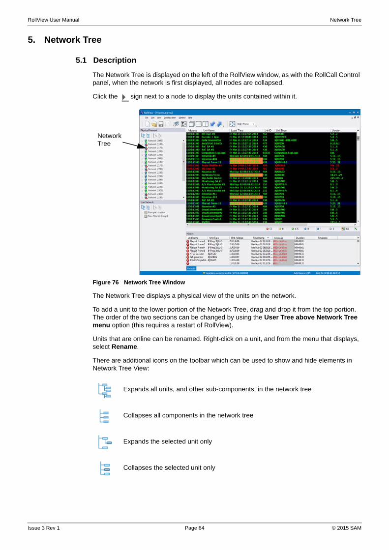
RollView User Manual Network Tree
5. Network Tree
5.1 Description
The Network Tree is displayed on the left of the RollView window, as with the RollCall Control panel, when the network is first displayed, all nodes are collapsed.
Click the sign next to a node to display the units contained within it.
Figure 76 Network Tree Window
The Network Tree displays a physical view of the units on the network.
To add a unit to the lower portion of the Network Tree, drag and drop it from the top portion. The order of the two sections can be changed by using the User Tree above Network Tree menu option (this requires a restart of RollView).
Units that are online can be renamed. Right-click on a unit, and from the menu that displays, select Rename.
There are additional icons on the toolbar which can be used to show and hide elements in Network Tree View:
Expands all units, and other sub-components, in the network tree
Collapses all components in the network tree
Expands the selected unit only
Collapses the selected unit only
Network Tree
Issue 3 Rev 1 Page 64 © 2015 SAM
RollView User Manual Network Tree
5.2 Auto Discovery
Auto discovery mode can be enabled from the configuration menu, and "Auto Discovery Active" displays on the status bar when it is operational.
When active, auto discovery automatically adds new cards/frames/networks/devices to the current list without.
In combination with Filtered groups there is the possibility to instantly monitor new network items as soon as they are added to the network.
The expected usage of this mode is first manually add all the units to the unit list. Then activate "Auto discovery Mode".
Auto discovery mode is disabled if you change the unit list manually and on startup of RollView.
Issue 3 Rev 1 Page 65 © 2015 SAM

RollView User Manual User Tree
6. User Tree
6.1 Description
The User Tree window is used to build custom tree views of network components. To organize components within the User Tree there are:
• Location—For creating trees within.
• Filtered Groups—Automatically add components based upon user-defined rules.
• Folders—For organizing components within Locations or Filtered groups.
Figure 77 User Tree Window
The User View can be customized to display selected units, allowing easy access to units of particular relevancy.
:
Each of these show an aggregated state of all the components contained within them. This aggregated state is added as a header to a virtual unit. (see Appendix E) The address of the virtual unit can be specified on a per item basis by right-clicking on the item selecting the Virtual Unit menu option.
Expands all units, and other sub-components, in the User Tree
Collapses all components in the User Tree
Expands the selected unit only
Collapses the selected unit only
User Tree
Issue 3 Rev 1 Page 66 © 2015 SAM

RollView User Manual User Tree
Figure 78 Virtual Unit
If no virtual unit address is specified then the default address is used from the setting UserTreeVirtualUnitAddress in Configuration.cfg. Headers are created with names made up of the path to the tree item. For the example below the virtual headers would be:
-Test Room
-Test Room: Channel 2
Figure 79 Default Headers
Using the popup menu, items in the User Tree can be reordered by using the move up/down options, expand and contract.
6.1.1 Filtered Groups
Filtered groups are an auto-generated group of units based upon user-defined rules. Rules are defined using the Rules Engine (See Rules Engine on page 91.). The following example shows how to create a rule which adds all units that have Channel 01 OR Channel 2 in their INFORMATION2 header field.
1. From the User Tree popup menu select New Filtered Group.
2. Choose whether the new filtered group is added to the Test Room location or be the start of a new tree.
Figure 80 New Filtered Group Location
3. Select No.
Figure 81 Add Filtered Group Name
4. Click on the new filtered group icon, and the Rule Editor screen displays.
Issue 3 Rev 1 Page 67 © 2015 SAM
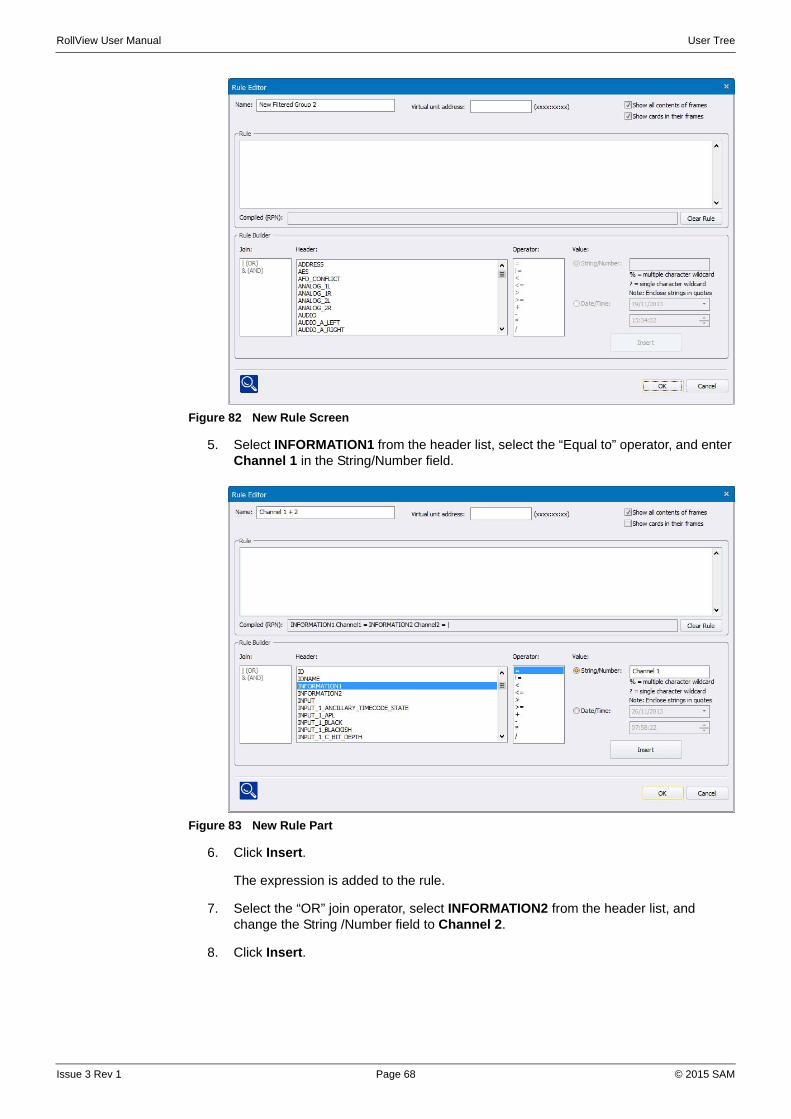
RollView User Manual User Tree
k
Figure 82 New Rule Screen
5. Select INFORMATION1 from the header list, select the “Equal to” operator, and enter Channel 1 in the String/Number field.
Figure 83 New Rule Part
6. Click Insert.
The expression is added to the rule.
7. Select the “OR” join operator, select INFORMATION2 from the header list, and change the String /Number field to Channel 2.
8. Click Insert.
Issue 3 Rev 1 Page 68 © 2015 SAM

RollView User Manual User Tree
Figure 84 Rule Added
The editor automatically wraps the existing expression in brackets, and inserts the new expression.
9. Click OK. The changes are saved.
10. Click OK and the new Filtered Group Channel 1 displays in the User Tree View and it automatically list all units that have their INFORMATION2 field as Channel 01.
Figure 85 Unit List
Other options include "Show all contents of frames", with this enabled if a card or a frame is matched by the rule then all the other cards within that frame are added. Also the option Show cards in their frames" adds the frame of a matched card and shows the card within it.
Note: The rule can be manually edited within the edit box, to remove brackets, or to change the rule. If the edit box displays red instead of green the rule is invalid and the syntax should be checked.
Issue 3 Rev 1 Page 69 © 2015 SAM
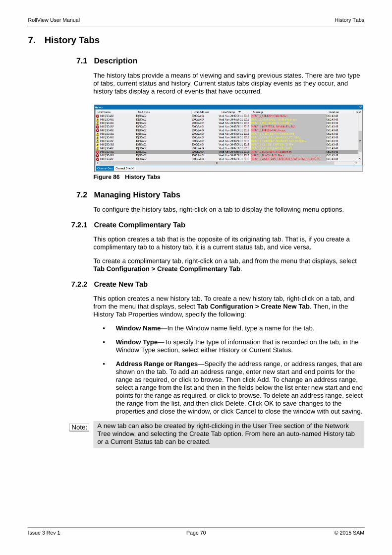
RollView User Manual History Tabs
7. History Tabs
7.1 Description
The history tabs provide a means of viewing and saving previous states. There are two type of tabs, current status and history. Current status tabs display events as they occur, and history tabs display a record of events that have occurred.
Figure 86 History Tabs
7.2 Managing History Tabs
To configure the history tabs, right-click on a tab to display the following menu options.
7.2.1 Create Complimentary Tab
This option creates a tab that is the opposite of its originating tab. That is, if you create a complimentary tab to a history tab, it is a current status tab, and vice versa.
To create a complimentary tab, right-click on a tab, and from the menu that displays, select Tab Configuration > Create Complimentary Tab.
7.2.2 Create New Tab
This option creates a new history tab. To create a new history tab, right-click on a tab, and from the menu that displays, select Tab Configuration > Create New Tab. Then, in the History Tab Properties window, specify the following:
• Window Name—In the Window name field, type a name for the tab.
• Window Type—To specify the type of information that is recorded on the tab, in the Window Type section, select either History or Current Status.
• Address Range or Ranges—Specify the address range, or address ranges, that are shown on the tab. To add an address range, enter new start and end points for the range as required, or click to browse. Then click Add. To change an address range, select a range from the list and then in the fields below the list enter new start and end points for the range as required, or click to browse. To delete an address range, select the range from the list, and then click Delete. Click OK to save changes to the properties and close the window, or click Cancel to close the window with out saving.
Note: A new tab can also be created by right-clicking in the User Tree section of the Network Tree window, and selecting the Create Tab option. From here an auto-named History tab or a Current Status tab can be created.
Issue 3 Rev 1 Page 70 © 2015 SAM

RollView User Manual History Tabs
Figure 87 History Tab Properties
7.2.3 Move Tab Order Left/Right
Use these options to rearrange the order in which the tabs are displayed. To move a tab to the right, right-click on it and select Tab Configuration > Move Tab Order Right. To move a tab to the left, right-click on it and select Tab Configuration > Move Tab Order Left.
7.2.4 Delete Tab
To remove a tab, right-click on it and select Tab Configuration > Delete Tab.
7.2.5 History Tab Log File Setup
Use this option to enable or disable log file creation for a tab, and to specify the location and file-naming convention to be used for the log file.
To enable log file creation, select Enable log file. The log file is created according to the parameters specified. To use an automatically generated file name, which is based on time and date, select Use automatic filename based on Time/Date. Then, in the Automatic filename section, specify the path to the directory in which the generated log files are to be stored. This must be in a local or network accessible directory. The file name is in the format dd-mm-yy.log.
When using automatic file names, the following variables can be used to add additional information to the file name:
• %a Abbreviated weekday name (3 characters)
• %b Abbreviated month name (3 characters)
• %d Day of the month as a decimal number (01-31)
• %H Hour in 24-hour format (00-23)
• %I Hour in 12-hour format (01-12)
• %j Day of the year as a decimal number (001-366)
• %m Month as a decimal number (01-12)
Issue 3 Rev 1 Page 71 © 2015 SAM
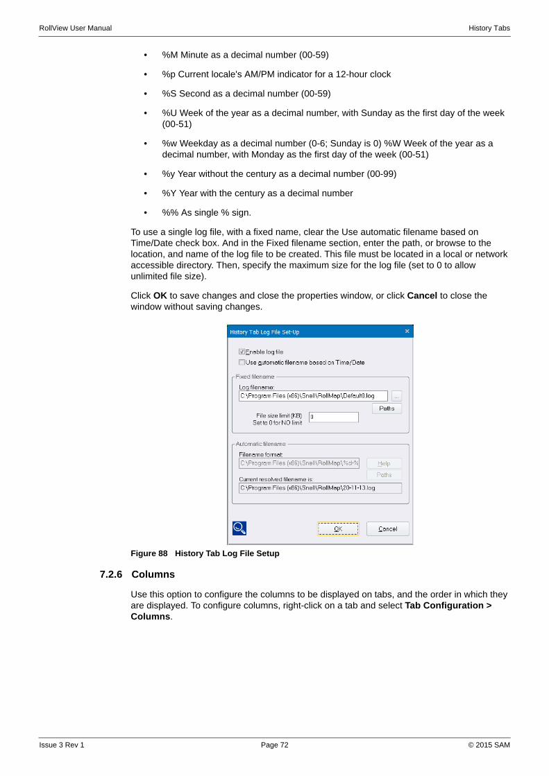
RollView User Manual History Tabs
• %M Minute as a decimal number (00-59)
• %p Current locale's AM/PM indicator for a 12-hour clock
• %S Second as a decimal number (00-59)
• %U Week of the year as a decimal number, with Sunday as the first day of the week (00-51)
• %w Weekday as a decimal number (0-6; Sunday is 0) %W Week of the year as a decimal number, with Monday as the first day of the week (00-51)
• %y Year without the century as a decimal number (00-99)
• %Y Year with the century as a decimal number
• %% As single % sign.
To use a single log file, with a fixed name, clear the Use automatic filename based on Time/Date check box. And in the Fixed filename section, enter the path, or browse to the location, and name of the log file to be created. This file must be located in a local or network accessible directory. Then, specify the maximum size for the log file (set to 0 to allow unlimited file size).
Click OK to save changes and close the properties window, or click Cancel to close the window without saving changes.
Figure 88 History Tab Log File Setup
7.2.6 Columns
Use this option to configure the columns to be displayed on tabs, and the order in which they are displayed. To configure columns, right-click on a tab and select Tab Configuration > Columns.
Issue 3 Rev 1 Page 72 © 2015 SAM
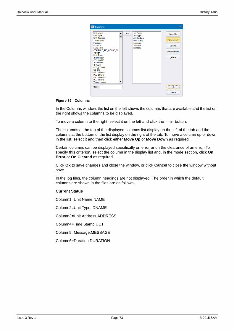
RollView User Manual History Tabs
Figure 89 Columns
In the Columns window, the list on the left shows the columns that are available and the list on the right shows the columns to be displayed.
To move a column to the right, select it on the left and click the button.
The columns at the top of the displayed columns list display on the left of the tab and the columns at the bottom of the list display on the right of the tab. To move a column up or down in the list, select it and then click either Move Up or Move Down as required.
Certain columns can be displayed specifically on error or on the clearance of an error. To specify this criterion, select the column in the display list and, in the mode section, click On Error or On Cleared as required.
Click Ok to save changes and close the window, or click Cancel to close the window without save.
In the log files, the column headings are not displayed. The order in which the default columns are shown in the files are as follows:
Current Status
Column1=Unit Name,NAME
Column2=Unit Type,IDNAME
Column3=Unit Address,ADDRESS
Column4=Time Stamp,UCT
Column5=Message,MESSAGE
Column6=Duration,DURATION
Issue 3 Rev 1 Page 73 © 2015 SAM
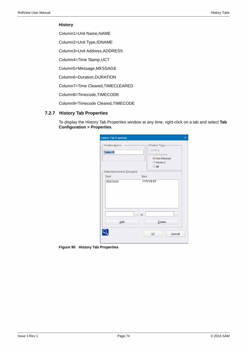
RollView User Manual History Tabs
History
Column1=Unit Name,NAME
Column2=Unit Type,IDNAME
Column3=Unit Address,ADDRESS
Column4=Time Stamp,UCT
Column5=Message,MESSAGE
Column6=Duration,DURATION
Column7=Time Cleared,TIMECLEARED
Column8=Timecode,TIMECODE
Column9=Timecode Cleared,TIMECODE
7.2.7 History Tab Properties
To display the History Tab Properties window at any time, right-click on a tab and select Tab Configuration > Properties.
Figure 90 History Tab Properties
Issue 3 Rev 1 Page 74 © 2015 SAM
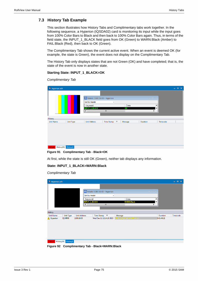
RollView User Manual History Tabs
7.3 History Tab Example
This section illustrates how History Tabs and Complimentary tabs work together. In the following sequence, a Hyperion (IQSDA02) card is monitoring its input while the input goes from 100% Color Bars to Black and then back to 100% Color Bars again. Thus, in terms of the field state, the INPUT_1_BLACK field goes from OK (Green) to WARN:Black (Amber) to FAIL:Black (Red), then back to OK (Green).
The Complimentary Tab shows the current active event. When an event is deemed OK (for example, the state is Green), the event does not display on the Complimentary Tab.
The History Tab only displays states that are not Green (OK) and have completed; that is, the state of the event is now in another state.
Starting State: INPUT_1_BLACK=OK
Complimentary Tab
Figure 91 Complimentary Tab - Black=OK
At first, while the state is still OK (Green), neither tab displays any information.
State: INPUT_1_BLACK=WARN:Black
Complimentary Tab
Figure 92 Complimentary Tab - Black=WARN:Black
Issue 3 Rev 1 Page 75 © 2015 SAM

RollView User Manual History Tabs
When the state changes to INPUT_1_BLACK=WARN:Black (Amber), because it is no longer Green and is an active event, the state is displayed on the Complimentary Tab. However, because it has not yet completed, nothing is displayed on the History Tab.
State: INPUT_1_BLACK=FAIL:Black
Complimentary Tab
Figure 93 Complimentary Tab - Black=FAIL:Black
History Tab
Figure 94 History Tab - Black=FAIL:Black
When the state changes from INPUT_1_BLACK=WARN:Black (Amber) to INPUT_1_BLACK=FAIL:Black (Red), the active event (INPUT_1_BLACK=FAIL:Black) is displayed on the Complimentary Tab. The event that has just completed (INPUT_1_BLACK=WARN:Black) is now displayed on the History Tab.
Issue 3 Rev 1 Page 76 © 2015 SAM

RollView User Manual History Tabs
State: INPUT_1_BLACK=OK
Complimentary Tab
Figure 95 Complimentary Tab - Black=OK
History Tab
Figure 96 History Tab - Black=OK
Finally, when the state returns to OK (Green), because there are no longer any active events, the Complimentary Tab displays nothing. The History Tab now displays both completed events, INPUT_1_BLACK=WARN:Black (Amber) and INPUT_1_BLACK=FAIL:Black (Red).
Table 2. summarizes the above example.
State Complimentary Tab displays... History tab displays...
OK (Green) Nothing Nothing
WARN (Amber) INPUT_1_BLACK=WARN:Black Nothing
FAIL (Red) INPUT_1_BLACK=FAIL:Black INPUT_1_BLACK=WARN:Black
OK (Green) NothingINPUT_1_BLACK=WARN:BlackINPUT_1_BLACK=FAIL:Black
Table 2. History Tab Displays
Issue 3 Rev 1 Page 77 © 2015 SAM
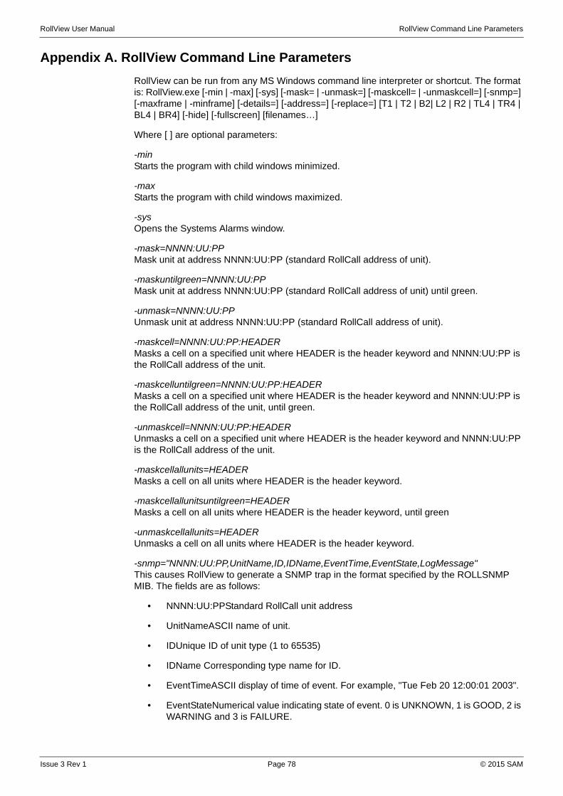
RollView User Manual RollView Command Line Parameters
Appendix A. RollView Command Line Parameters
RollView can be run from any MS Windows command line interpreter or shortcut. The format is: RollView.exe [-min | -max] [-sys] [-mask= | -unmask=] [-maskcell= | -unmaskcell=] [-snmp=] [-maxframe | -minframe] [-details=] [-address=] [-replace=] [T1 | T2 | B2| L2 | R2 | TL4 | TR4 | BL4 | BR4] [-hide] [-fullscreen] [filenames…]
Where [ ] are optional parameters:
-min Starts the program with child windows minimized.
-max Starts the program with child windows maximized.
-sysOpens the Systems Alarms window.
-mask=NNNN:UU:PPMask unit at address NNNN:UU:PP (standard RollCall address of unit).
-maskuntilgreen=NNNN:UU:PPMask unit at address NNNN:UU:PP (standard RollCall address of unit) until green.
-unmask=NNNN:UU:PPUnmask unit at address NNNN:UU:PP (standard RollCall address of unit).
-maskcell=NNNN:UU:PP:HEADERMasks a cell on a specified unit where HEADER is the header keyword and NNNN:UU:PP is the RollCall address of the unit.
-maskcelluntilgreen=NNNN:UU:PP:HEADERMasks a cell on a specified unit where HEADER is the header keyword and NNNN:UU:PP is the RollCall address of the unit, until green.
-unmaskcell=NNNN:UU:PP:HEADERUnmasks a cell on a specified unit where HEADER is the header keyword and NNNN:UU:PP is the RollCall address of the unit.
-maskcellallunits=HEADERMasks a cell on all units where HEADER is the header keyword.
-maskcellallunitsuntilgreen=HEADERMasks a cell on all units where HEADER is the header keyword, until green
-unmaskcellallunits=HEADERUnmasks a cell on all units where HEADER is the header keyword.
-snmp="NNNN:UU:PP,UnitName,ID,IDName,EventTime,EventState,LogMessage"This causes RollView to generate a SNMP trap in the format specified by the ROLLSNMP MIB. The fields are as follows:
• NNNN:UU:PPStandard RollCall unit address
• UnitNameASCII name of unit.
• IDUnique ID of unit type (1 to 65535)
• IDName Corresponding type name for ID.
• EventTimeASCII display of time of event. For example, "Tue Feb 20 12:00:01 2003".
• EventStateNumerical value indicating state of event. 0 is UNKNOWN, 1 is GOOD, 2 is WARNING and 3 is FAILURE.
Issue 3 Rev 1 Page 78 © 2015 SAM

RollView User Manual RollView Command Line Parameters
• LogMessageRollCall log message that generated this event. For example, "INPUT=LOST"
All fields must be comma separated and hence the fields themselves must not contain commas. Any field that contains a space must be enclosed by double quotes.
Example: -snmp="0000:50:05,DA5,56,IQDVDA,Wed Feb 21 12:00:00 2003,3,INPUT=LOST"
-maxframe This maximizes the whole RollView window.
-minframe This minimizes the whole RollView window.
-details=NNNN:UU:PPThis brings up the "Details" window for the unit at address NNNN:UU:PP.
filename -T1Open file and place new window as full screen of client area within RollView
filename -T2Open file and place new window at top half of the client area within RollView
filename -B2Open file and place new window at bottom half of the client area within RollView
filename -L2Open file and place new window at left half of the client area within RollView
filename -R2Open file and place new window at right half of the client area within RollView
filename -TL4Open file and place new window at top left quarter of the client area within RollView
filename -TR4Open file and place new window at top right quarter of the client area within RollView
filename -BL4Open file and place new window at bottom left quarter of the client area within RollView
filename -BR4Open file and place new window at bottom right quarter of the client area within RollView
-hide Hides the RollView window and places a small icon in the Taskbar icon area.
-fullscreen Starts the program in Fullscreen mode
filename is the paths of 1 or more Alarm files with the extensions ALM. Long file names with spaces in them must be enclosed with double quotes. If the file name has the extension .WAV, it is assumed to be a standard sound file and RollView plays the file through the standard sound device.
-logdata
Allows a RollCall message to be sent to the currently configured LogServer. The client logging must be enabled and the following text must be a valid RollView sentence to work correctly. Also, the source address may be embedded in the message in one of the following formats:
Issue 3 Rev 1 Page 79 © 2015 SAM
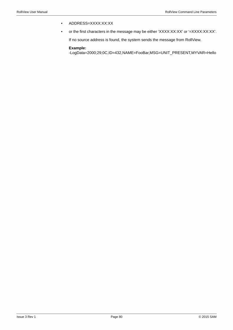
RollView User Manual RollView Command Line Parameters
• ADDRESS=XXXX:XX:XX
• or the first characters in the message may be either ‘XXXX:XX:XX’ or ‘=XXXX:XX:XX’.
If no source address is found, the system sends the message from RollView.
Example: -LogData=2000;29;0C,ID=432,NAME=FooBar,MSG=UNIT_PRESENT,MYVAR=Hello
Issue 3 Rev 1 Page 80 © 2015 SAM
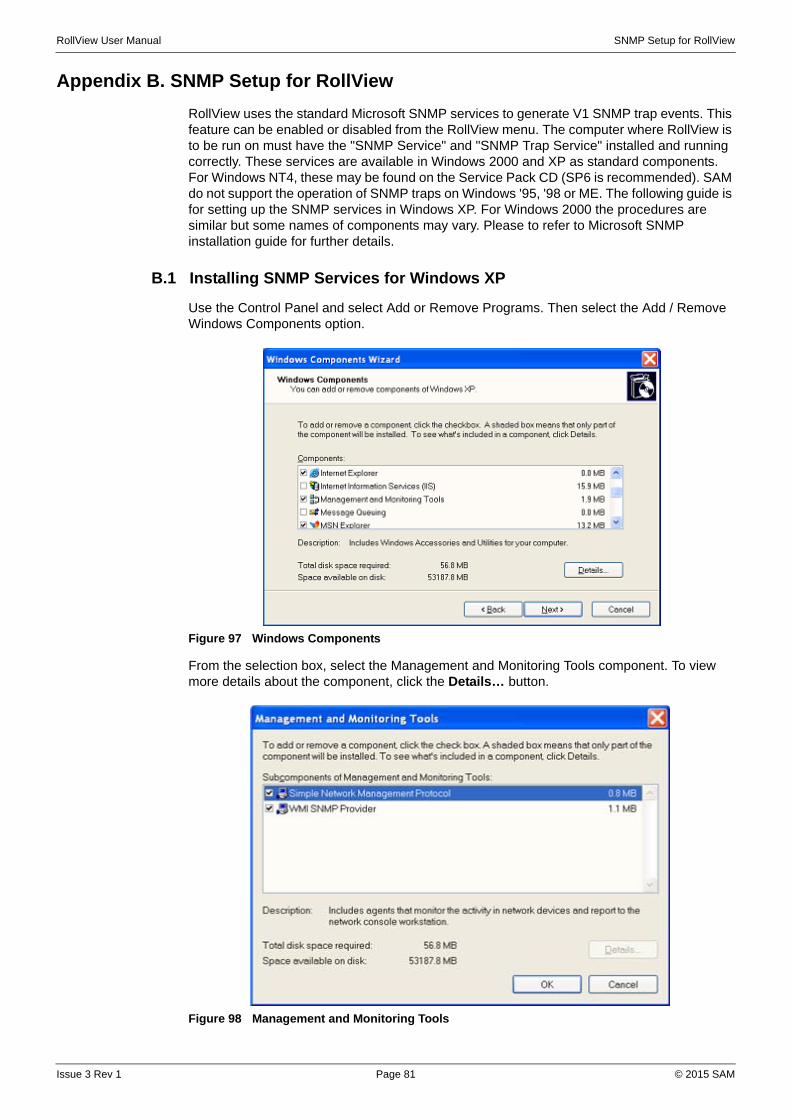
RollView User Manual SNMP Setup for RollView
Appendix B. SNMP Setup for RollView
RollView uses the standard Microsoft SNMP services to generate V1 SNMP trap events. This feature can be enabled or disabled from the RollView menu. The computer where RollView is to be run on must have the "SNMP Service" and "SNMP Trap Service" installed and running correctly. These services are available in Windows 2000 and XP as standard components. For Windows NT4, these may be found on the Service Pack CD (SP6 is recommended). SAM do not support the operation of SNMP traps on Windows '95, '98 or ME. The following guide is for setting up the SNMP services in Windows XP. For Windows 2000 the procedures are similar but some names of components may vary. Please to refer to Microsoft SNMP installation guide for further details.
B.1 Installing SNMP Services for Windows XP
Use the Control Panel and select Add or Remove Programs. Then select the Add / Remove Windows Components option.
Figure 97 Windows Components
From the selection box, select the Management and Monitoring Tools component. To view more details about the component, click the Details… button.
Figure 98 Management and Monitoring Tools
Issue 3 Rev 1 Page 81 © 2015 SAM
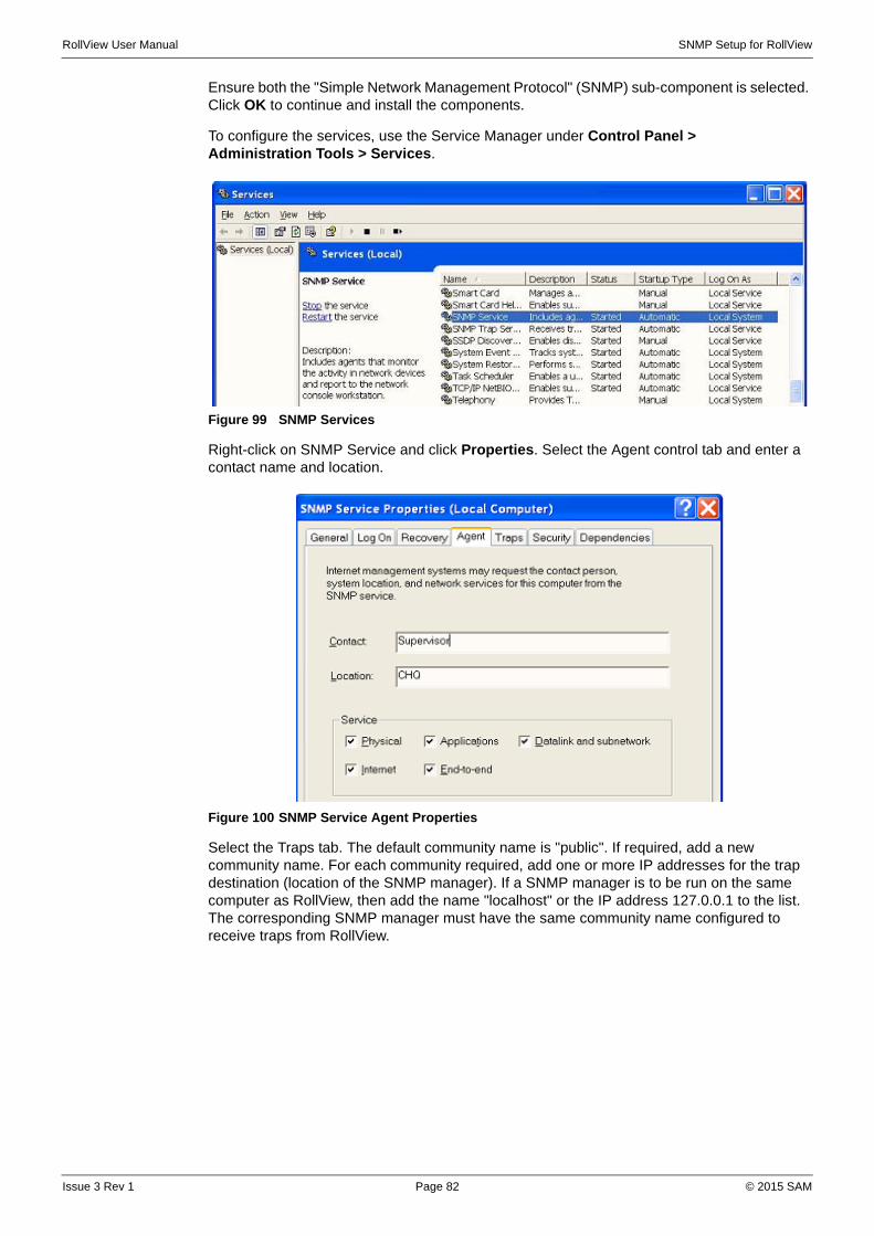
RollView User Manual SNMP Setup for RollView
Ensure both the "Simple Network Management Protocol" (SNMP) sub-component is selected. Click OK to continue and install the components.
To configure the services, use the Service Manager under Control Panel > Administration Tools > Services.
Figure 99 SNMP Services
Right-click on SNMP Service and click Properties. Select the Agent control tab and enter a contact name and location.
Figure 100 SNMP Service Agent Properties
Select the Traps tab. The default community name is "public". If required, add a new community name. For each community required, add one or more IP addresses for the trap destination (location of the SNMP manager). If a SNMP manager is to be run on the same computer as RollView, then add the name "localhost" or the IP address 127.0.0.1 to the list. The corresponding SNMP manager must have the same community name configured to receive traps from RollView.
Issue 3 Rev 1 Page 82 © 2015 SAM
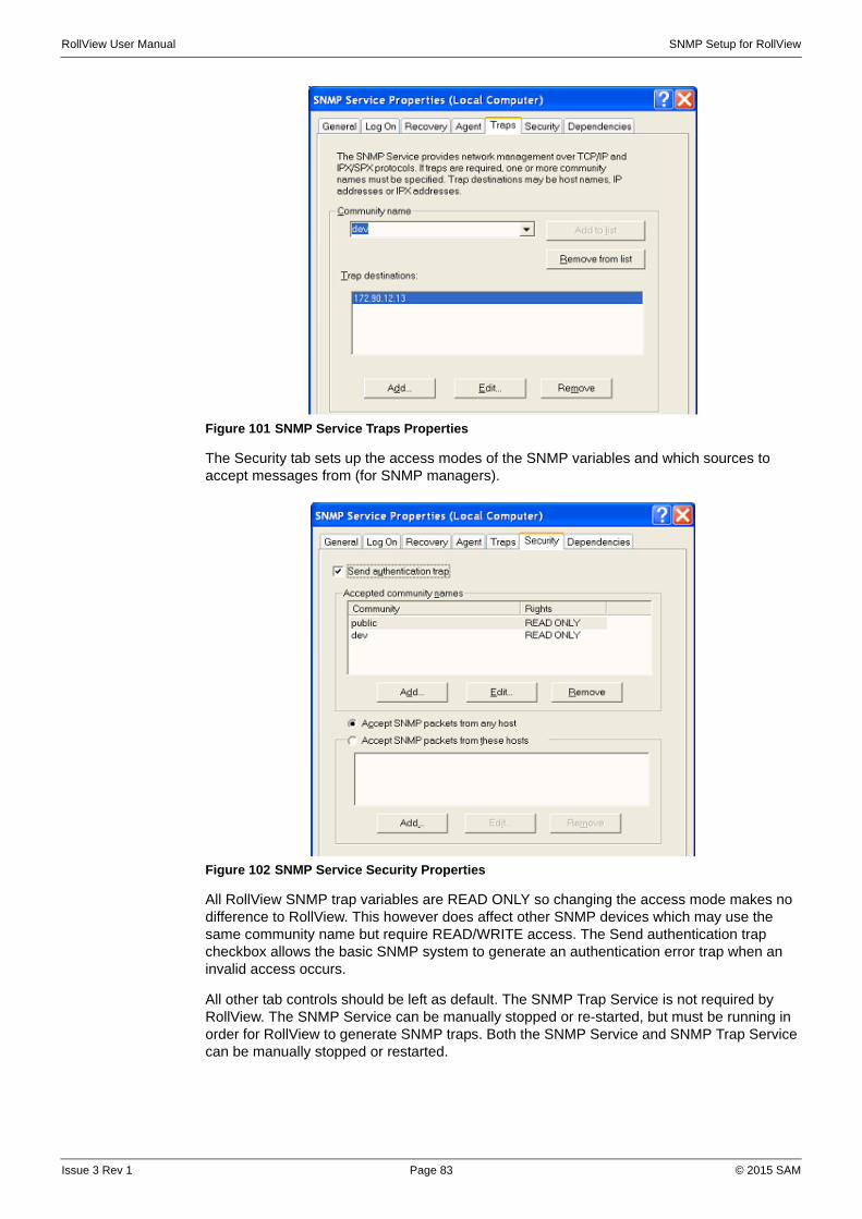
RollView User Manual SNMP Setup for RollView
Figure 101 SNMP Service Traps Properties
The Security tab sets up the access modes of the SNMP variables and which sources to accept messages from (for SNMP managers).
Figure 102 SNMP Service Security Properties
All RollView SNMP trap variables are READ ONLY so changing the access mode makes no difference to RollView. This however does affect other SNMP devices which may use the same community name but require READ/WRITE access. The Send authentication trap checkbox allows the basic SNMP system to generate an authentication error trap when an invalid access occurs.
All other tab controls should be left as default. The SNMP Trap Service is not required by RollView. The SNMP Service can be manually stopped or re-started, but must be running in order for RollView to generate SNMP traps. Both the SNMP Service and SNMP Trap Service can be manually stopped or restarted.
Issue 3 Rev 1 Page 83 © 2015 SAM
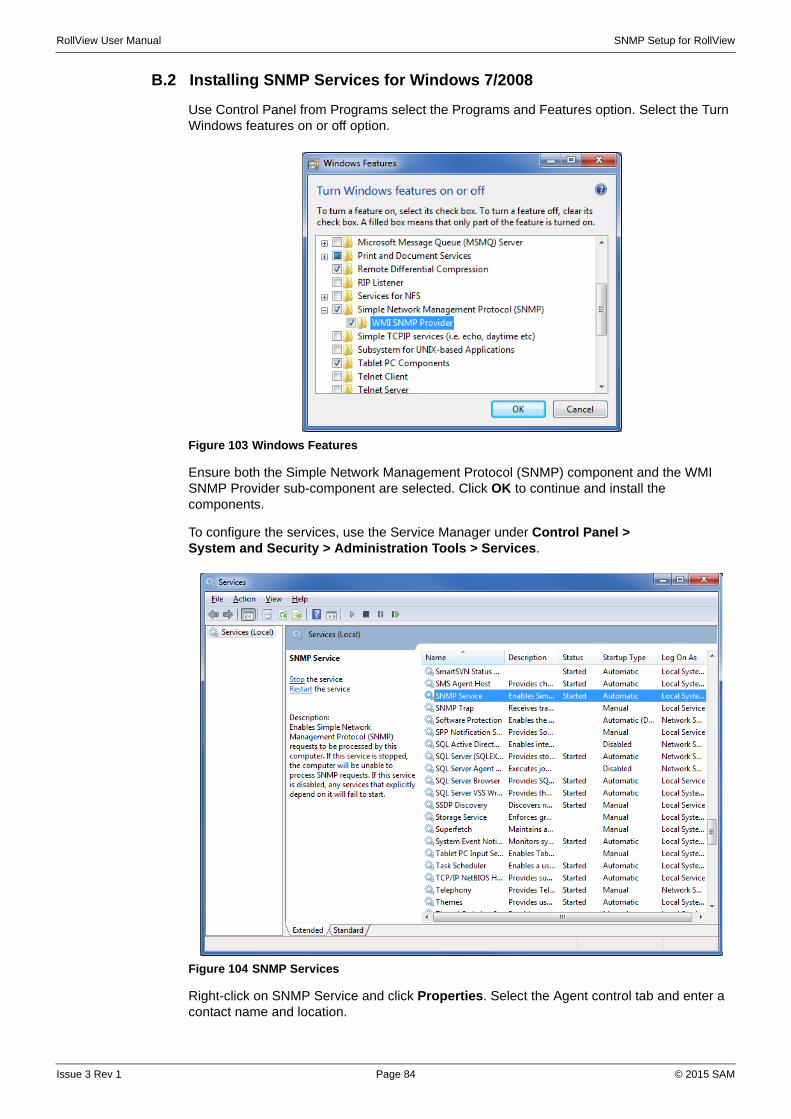
RollView User Manual SNMP Setup for RollView
B.2 Installing SNMP Services for Windows 7/2008
Use Control Panel from Programs select the Programs and Features option. Select the Turn Windows features on or off option.
Figure 103 Windows Features
Ensure both the Simple Network Management Protocol (SNMP) component and the WMI SNMP Provider sub-component are selected. Click OK to continue and install the components.
To configure the services, use the Service Manager under Control Panel > System and Security > Administration Tools > Services.
Figure 104 SNMP Services
Right-click on SNMP Service and click Properties. Select the Agent control tab and enter a contact name and location.
Issue 3 Rev 1 Page 84 © 2015 SAM

RollView User Manual SNMP Setup for RollView
Figure 105 SNMP Services Agent Properties
Select the Traps tab. The default community name is "public". If required, add a new community name. For each community required, add one or more IP addresses for the trap destination (location of the SNMP manager). If a SNMP manager is to be run on the same computer as RollView, then add the name "localhost" or the IP address 127.0.0.1 to the list. The corresponding SNMP manager must have the same community name configured to receive traps from RollView.
Figure 106 SNMP Services Traps Properties
Issue 3 Rev 1 Page 85 © 2015 SAM

RollView User Manual SNMP Setup for RollView
The Security tab sets up the access modes of the SNMP variables and which sources to accept messages from (for SNMP managers).
Figure 107 SNMP Services Security Properties
All RollView SNMP trap variables are READ ONLY so changing the access mode makes no difference to RollView. This however does affect other SNMP devices which may use the same community name but require READ/WRITE access. The Send authentication trap checkbox allows the basic SNMP system to generate an authentication error trap when an invalid access occurs.
All other tab controls should be left as default. The SNMP Trap Service is not required by RollView. The SNMP Service can be manually stopped or re-started, but must be running in order for RollView to generate SNMP traps. Both the SNMP Service and SNMP Trap Service can be manually stopped or re-started.
Issue 3 Rev 1 Page 86 © 2015 SAM
RollView User Manual Integrating RollView with Volicon Observer
Appendix C. Integrating RollView with Volicon Observer
C.1 Overview
RollView can be integrated fully with Volicon Observer monitoring and logging software.
To configure Volicon integration:
1. Install and configure Volicon Observer. This is not described in this manual; please refer to the Volicon documentation.
2. Set up the RollView Links menu in the Configuration.cfg file. See Configuring Shortcut Links below.
3. Edit the Gateway template pages to set the correct INFORMATION2 log field (for the IQHIP00). See Setting up the INFORMATION2 Log Field on page 88.
4. Create History Tabs and Complimentary Tabs monitoring each Hyperion (IQHIP00) card per Volicon channel. See Setting up the RollView History Tabs on page 89.
The system is now ready to use. See Working with Volicon Observer on page 89.
C.2 Configuring Shortcut Links
After Volicon Observer is set up and running, the RollCall Links menu must be set up to access Observer.
To configure the Links menu, edit the Configuration.cfg file, which is located in the installation directory. By default, the location of this file is:
C:\Program Files\SAM\RollView\Configuration\Configuration.cfg, orC:\Program Files (x86)\SAM\RollView\Configuration\Configuration.cfg
Open this file in a text editor such as Notepad, and in the [AlarmViewRightClickAllUnits] section, add an entry similar to this:
Item1=View video in Volicon Observer,"C:\Program Files\Internet Explorer\iexplore.exe"192.168.50.90/monitor.php?ch=#Information2#&time=#UCT#
Where:
View video in Volicon Observeris the name the that displays in the links menu.
"C:\Program Files\Internet Explorer\iexplore.exe"
is the link to the Internet Explorer Program. This can be set to another type of browser if required.
192.168.50.90is the IP address of the Volicon Server PC. This can also be a DNS recognizable name.
/monitor.php?ch=#Information2#&time=#UCT#is the text required by the Volicon Server. This text should always be exactly as displayed here.
Issue 3 Rev 1 Page 87 © 2015 SAM

RollView User Manual Integrating RollView with Volicon Observer
For example:
[AlarmViewRightClickAllUnits]
Item0=Launch RollCall Control,<CONTROL PANEL>
Item1=View video in Volicon Observer,"C:\Program Files\Internet Explorer\iexplore.exe"192.168.50.90/monitor.php?ch=#Information2#&time=#UCT#
After editing the Configuration.cfg file, save the changes and restart RollView. To check that the Links menu has been changed, highlight a unit in the System Alarms window, right-click on it and follow the Links entry. The Links menu displays as shown in Figure 108
Figure 108 Links Menu
C.3 Setting up the INFORMATION2 Log Field
A Volicon Observer system is normally set up to monitor four video feeds. A Hyperion-enabled card (IQSDA02 or IQHIP00) monitors the video, then the feed goes on to the Volicon Observer system. Volicon Observer can only integrate Hyperion cards that have a specific log field enabled, INFORMATION2. When integrating the systems, the standard convention is to edit the INFORMATION2 field on each IQSDA02 or IQHIP00 card and set to Channelxx, where xx identifies a number (i.e. Channel01, Channel02, Channel04 etc.).
To set up the INFORMATION2 log field, open the RollCall Control Panel of the Gateway card hosting the Hyperion card. Navigate to the relevant Slots dialog page and edit the 2nd Information Field. For more information, refer to the IQH3 chassis operator's manual.
Issue 3 Rev 1 Page 88 © 2015 SAM
RollView User Manual Integrating RollView with Volicon Observer
C.4 Setting up the RollView History Tabs
For each Hyperion card monitoring a Volicon channel, create a History Tab and a Complimentary Tab. It is important to set up both a History Tab and a Complimentary Tab. The Complimentary Tab will display the current alarm (any non-green event), while the History Tab records the last changed state and its duration.
To make using the tabs easier, mask any event that you are not interested in.
See Auto discovery mode is disabled if you change the unit list manually and on startup of RollView. on page 65.
C.5 Working with Volicon Observer
Volicon Observer records video and allows review of previous material using a TIMECODE key. To view an event with Volicon, select the event from either the History Tab or the Complimentary Tab. Right-click and navigate to View video in Volicon Observer. This opens the Volicon viewer at the specified TIMECODE event.
Issue 3 Rev 1 Page 89 © 2015 SAM

RollView User Manual Virtual Units
Issue 3 Rev 1 Page 90 © 2015 SAM
Appendix D. Virtual Units
D.1 Overview
Virtual units are used in number of different ways:
• Reporting of aggregate states from the User Network Tree
• Receiving data from the Get SNMP action
The virtual units and their virtual headers can be treated in exactly the same way is real units and headers. You can use them in Alarm Actions, History Tabs, etc.
D.2 Troubleshooting
D.2.1 Cannot see virtual unit in User Alarms View
Check that they have been added to the Unit List.
D.2.2 Cannot see the virtual header in User Alarms View
Ensure that you have either added the column manually to the User Alarms View or have run Create All Headers.

RollView User Manual Rules Engine
Appendix E. Rules Engine
E.1 Overview
The rule editor allows you to create complex expressions based upon data from units and their log fields. Rules that evaluate to True/False are typically used for filtering data (for example, when used in filtered groups and QC reports), however, rules may also be defined that evaluate to a string or decimal; which are often used in log field logic for the creation of new log fields, from existing ones.
E.2 Rule Editor
The Rule Editor is shown in Figure 109
Figure 109 Rule Editor
The Rule Editor provides the following features:
• Syntax checking of rules in each key press
• A rule builder for inserting queries into the rule
• Operators: Equal to, Not equal to, Less than, Less than or equal to, greater than, greater than or equal to, addition, subtraction, multiplication, and division
• Query on string, number (decimal, integer, RollView unit address), or date and time
E.2.1 Rule Editor Settings
Name The name of the filtered group. This name can be edited.For QC reports and Log Logic this field is unused.
Virtual Unit Address Used to define a new virtual unit that is used to store the aggregate result from the rule.
Show all contents of frames Frames displayed in the filtered group also display the cards within the frames.
Show cards in their frames Cards displayed in the filtered group display the frame they belong to.
Compiled RPN A read-only information field, that reads from right to left, and is used to help with debugging a rule. For example, it may help indicate if brackets are required around parts of the rule.
Issue 3 Rev 1 Page 91 © 2015 SAM

RollView User Manual Rules Engine
E.3 Example Rules
E.3.1 Example 1
The following example creates a rule that matches any unit that has the INFORMATION2 field as either Channel 01 or Channel 02.
Figure 110 New Rule Screen
1. Select INFORMATION1 from the header list, select the “Equal to” operator, and enter Channel 1 in the String/Number field.
Figure 111 New Rule Part
2. Click Insert.
The expression is added to the rule.
3. Select the “OR” join operator, select INFORMATION2 from the header list, and change the String/Number field to Channel 2.
Issue 3 Rev 1 Page 92 © 2015 SAM

RollView User Manual Rules Engine
4. Click Insert.
Figure 112 Rule Added
The editor automatically wraps the existing expression in brackets, and inserts the new expression.
5. Click OK.
The changes are saved.
E.3.2 Example 2
The following example creates a rule within Log Field logic to add two separate numeric log fields and display the result formatted as a string.
Figure 113 Log Field Logic Screen
1. Open the Log Field Logic screen (right click on a system alarm, and select Log Field Logic from the menu).
Note: The rule can be manually edited within the edit box, to remove brackets, or to change the rule. If the edit box displays red instead of green the rule is invalid and the syntax should be checked.
Issue 3 Rev 1 Page 93 © 2015 SAM
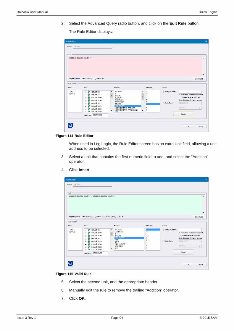
RollView User Manual Rules Engine
2. Select the Advanced Query radio button, and click on the Edit Rule button.
The Rule Editor displays.
Figure 114 Rule Editor
When used in Log Logic, the Rule Editor screen has an extra Unit field, allowing a unit address to be selected.
3. Select a unit that contains the first numeric field to add, and select the “Addition” operator.
4. Click Insert.
Figure 115 Valid Rule
5. Select the second unit, and the appropriate header.
6. Manually edit the rule to remove the trailing “Addition” operator.
7. Click OK.
Issue 3 Rev 1 Page 94 © 2015 SAM
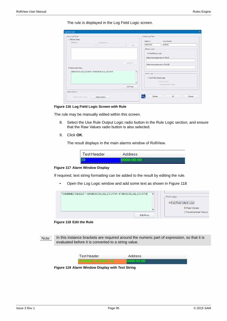
RollView User Manual Rules Engine
The rule is displayed in the Log Field Logic screen.
Figure 116 Log Field Logic Screen with Rule
The rule may be manually edited within this screen.
8. Select the Use Rule Output Logic radio button in the Rule Logic section, and ensure that the Raw Values radio button is also selected.
9. Click OK.
The result displays in the main alarms window of RollView.
Figure 117 Alarm Window Display
If required, text string formatting can be added to the result by editing the rule.
• Open the Log Logic window and add some text as shown in Figure 118
Figure 118 Edit the Rule
Figure 119 Alarm Window Display with Text String
Note: In this instance brackets are required around the numeric part of expression, so that it is evaluated before it is converted to a string value.
Issue 3 Rev 1 Page 95 © 2015 SAM
RollView User Manual Rules Engine
Note: The Create State Trigger and Alarm Actions buttons provide a convenient means of creating a global action on the logic driven field. Taking a different example, where two input fields (INPUT1=FAIL and INPUT2 = FAIL) are aggregated together by a Log Logic rule into a new field AGG_INPUT, the "Create State Trigger" button can be used to generate a state trigger on this field, and the "Alarms Actions" button provides a shortcut to the global alarm actions dialog where a standard action can be configured. Only when both fields go to FAIL will the trigger be fired.
Issue 3 Rev 1 Page 96 © 2015 SAM

RollView User Manual RollView Parameterization
Appendix F. RollView Parameterization
F.1 Relative Paths
Everywhere in RollView that a path is entered, (for example links to external commands to execute), you can enter a relative path, which is considered relative to the starting directory of the enclosing file.
RollView design mode automatically finds the best relative path when you browse for files. Alternatively search paths can be used. See “Search Paths” on page 97.
F.2 Search Paths
Everywhere in RollView that a path is entered, (for example links to external commands to execute), you can enter a combination of a base variable search path prefix, with a hard-coded suffix. The syntax is $varname$ where varname is the defined name of the search path variable. Search paths can be defined with absolute hard-coded values, or with nested values referencing other search paths. The key point is that you can edit the search path definitions in one central place, and have the changes ripple through to every use of that search path within the configured system.
This is an advanced feature and rarely used by SAM when we build RollView systems.
Search paths are intended to be case INsensitive, so $iq$ should work the same as $IQ$.
F.3 Macros
Everywhere in RollView that an executable command is specified, (for example an action triggered by pressing a configured button, or an action triggered from a customised right-click context menu, or an action triggered by a defined status from the live monitoring system), RollView allows you to reference command macros. The syntax is <macroname> to reference a defined macro, and the macros are defined centrally.
Q: What is the difference between macros and search paths?A: Search paths are intended to be used for paths, for example, directory names and/or file names. Macros can contain paths, but in addition they can contain other data, typically command line parameters being passed to the external program.
Worked example, as used in the SAM standard RollView library:
Macro definition:
<CONTROL_PANEL>=$CONTROL$ -runonce -u %a
Search path definitions:
$CONTROL$=$ROLLCALL$\Control Panel\Rollcall Control Panel.exe
$ROLLCALL$=C:\Program Files (x86)\SAM\RollCallSuite
Many places within the RollView library or a customer's configured system may call the macro <CONTROL_PANEL>. At run-time, this is expanded through the various nested macro and path definitions to resolve to an absolute external path reference:
C:\Program Files (x86)\SAM\RollCallSuite\Control Panel\Rollcall Control Panel.exe with various command line parameters appended: -runonce -u %a. (See below for explanation of %a.)
On a different PC, the RollCall Control Panel could be installed in a different location: C:\Program Files\... on a 32-bit PC, or C:\Programme\... on a French-language PC, or indeed any location chosen by the customer. By simply editing the one global search path definition for each PC, all of the buttons and other links to the Control Panel are automatically updated appropriate to each installed PC.
Issue 3 Rev 1 Page 97 © 2015 SAM
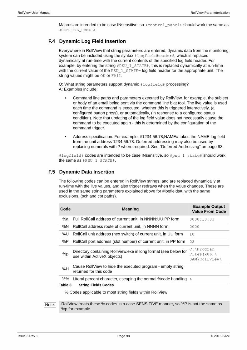
RollView User Manual RollView Parameterization
Macros are intended to be case INsensitive, so <control_panel> should work the same as <CONTROL_PANEL>.
F.4 Dynamic Log Field Insertion
Everywhere in RollView that string parameters are entered, dynamic data from the monitoring system can be included using the syntax #logfieldheader#, which is replaced dynamically at run-time with the current contents of the specified log field header. For example, by entering the string #PSU_1_STATE#, this is replaced dynamically at run-time with the current value of the PSU_1_STATE= log field header for the appropriate unit. The string values might be OK or FAIL.
Q: What string parameters support dynamic #logfield# processing?A: Examples include:
• Command line paths and parameters executed by RollView, for example, the subject or body of an email being sent via the command line blat tool. The live value is used each time the command is executed, whether this is triggered interactively, (a configured button press), or automatically, (in response to a configured status condition). Note that updating of the log field value does not necessarily cause the command to be executed again - this is determined by the configuration of the command trigger.
• Address specification. For example, #1234:56:78,NAME# takes the NAME log field from the unit address 1234.56.78. Deferred addressing may also be used by replacing numerals with ? where required. See “Deferred Addressing” on page 93.
#logfield# codes are intended to be case INsensitive, so #psu_1_state# should work the same as #PSU_1_STATE#.
F.5 Dynamic Data Insertion
The following codes can be entered in RollView strings, and are replaced dynamically at run-time with the live values, and also trigger redraws when the value changes. These are used in the same string parameters explained above for #logfields#, with the same exclusions, (sch and cpt paths).
% Codes applicable to most string fields within RollView
Code MeaningExample Output Value From Code
%a Full RollCall address of current unit, in NNNN:UU:PP form 0000:10:03
%N RollCall address route of current unit, in NNNN form 0000
%U RollCall unit address (hex switch) of current unit, in UU form 10
%P RollCall port address (slot number) of current unit, in PP form 03
%pDirectory containing RollView.exe in long format (see below for use within ActiveX objects)
C:\Program Files(x86)\SAM\RollView\
%HCause RollView to hide the executed program - empty string returned for this code
%% Literal percent character, escaping the normal %code handling %
Table 3. String Fields Codes
Note: RollView treats these % codes in a case SENSITIVE manner, so %P is not the same as %p for example.
Issue 3 Rev 1 Page 98 © 2015 SAM

RollView User Manual RollView Parameterization
Note: Different % fields are used within RollView time field definitions.
Issue 3 Rev 1 Page 99 © 2015 SAM