Rolling CuRtain dooR Manual - Trac Rite · Rolling CuRtain dooR Manual InstallatIon • MaIntenance...
12
ROLLING CURTAIN DOOR MANUAL INSTALLATION • MAINTENANCE • PARTS Model 944 PHONE 800 448 8979 FAX 800 236 8722 WEBSITE www.tracrite.com EMAIL [email protected] ADDRESS 314 Wilburn Road Sun Prairie, WI 53590 This manual MUST be left with the owner
Transcript of Rolling CuRtain dooR Manual - Trac Rite · Rolling CuRtain dooR Manual InstallatIon • MaIntenance...

Rolling CuRtain dooR Manual InstallatIon • MaIntenance • parts
Model 944
PHONE 800 448 8979FAX 800 236 8722wEbsitE www.tracrite.comEMAiL [email protected] ADDREss 314 wilburn Road sun Prairie, wi 53590
this manual MUst be left with the owner

ww
w.t
racr
ite.
com
T R A C - R I T E
Thank you for purchasing Trac-Rite’s model 944 door. The following is an instructional guide to take you through the steps of installing your new door. Be sure to read and understand this entire installation manual including the warnings, cautions, and notes before starting the installation of your new Trac-Rite door.
the following terms are defined as:wARNiNG - serious personal injury or death can result from failure to follow instructions.CAUtiON - minor injury or property damage can result from failure to follow instructions.NOtE - special attention should be given.
WARNING!Improper installation of anchoring devices or installation into unsound material may result in premature product wear, product failure, property damage or serious personal injury.
Rolling steel doors are large, heavy objects that move with the help of springs under extreme tension. Since moving objects and springs under tension can cause injuries, your safety and the safety of others depends on you reading and following the instructions in this manual. Check your work prior to operating door.
WARNING!
POTENTIAL HAZARD EFFECT PREVENTIONMOVING DOOR Can Cause Serious
Injury or DeathKeep people clear of opening while door is moving. Get help or use support when lifting new door into place.
EXTREME SPRINGTENSION
Can Cause Serious Injury or Death
Installation, repairs, and adjustments must be made by a qualified door mechanic using proper tools, methods, and instructions. Before winding torsion spring, make sure door is fully open and curtain is wrapped on barrel.
Components under extreme spring tension can cause SERIOUS INJURY or DEATH. Adjustments and repairs must be made by a qualified door mechanic using proper tools and instructions. Do NOT attempt to adjust door tension unless the door is in the “UP” position. Winding bar should be solid steel 1/2” diameter rod or 3/8” x 1/2” flat.
WARNING!
1
CAUTION!Spring Tension is Critical: Improper tensioning of the spring(s) can result in door damage and reduce the life of your door. The door should not slam up or down during operation. Please refer to Page 8; Fig. 12. No warranty claims will be honored due to damage caused by improperly tensioned spring(s).

800-448-8979
T R A C - R I T E
Proprietary Noticeinformation contained in this document is copyrighted by trac-Rite and may not be duplicated in full or part by any person without prior written approval of trac-Rite. its purpose is to provide the user with adequate detailed documentation to efficiently install a model 944 rolling curtain door.
For Customer Support regarding: Parts orders technical help Emergency support installation questions Damage shortages
Please Call: 1-800-448-8979
1. INSPeCtIoN:Door and Hardware: Upon receiving the door shipment, immediately inspect the door and hardware for damage. Verify the product received with the packing list. Damage and/or shortages should be reported immediately to trac-Rite customer service at 800-448-8979. Please have your bill of lading and packing list to reference when reporting shortages or damage. Do not install damaged material without authorization from trac-Rite.
2. PRePARAtIoN:Clean the work area. Remove all debris and sharp objects from the area where the door will be placed on the floor. sweep the area clean. it is also recommended that the door curtain assembly be placed on a piece of cloth or cardboard to help ensure that the finished door surfaces will not be damaged while the door is being prepared for installation.
Recommended tools for assembly:• Wrenches or sockets 7/16” and 1/2” sizes• Drill or screw gun• 3/8” and 7/16” hex drivers (wood mounting)• 5/16” hex driver and 3/8” drill bit (steel
mounting)• 5/16” and 7/16” hex drivers and 5/16”
masonry bit (concrete or masonry mounting)• C-clamps or vise grips• Safety glasses• Work gloves• Pliers
Door Opening inspection (See Figure 1):• Is the framed opening width and height the same
size as the door ordered? (A x B)• Are the door jambs plumb and square?• Is the floor level and square with the door jambs?• Is there adequate jamb side clearance? (E)• Is there adequate clearance above the door
curtain roll? (G)• is there adequate clearance in front of the roll? (F)• Are the jambs structurally and/or dimensionally
adequate to accept door brackets and guides?
2
SIDE VIEw FRONT VIEw
Figure 1
A - FRAMED OPENING wIDTH B - FRAMED OPENING HEIGHT C - MINIMUM BRACKET MOUNTING wIDTH:
4”[10cm] FOR METAL OR wOOD; 6”[15.2cm] FOR MASONRY
D - MINIMUM HEADER HEIGHT: 7-1/2”[19cm]
E - MINIMUM JAMB wIDTH: 2”[5cm] FOR METAL OR wOOD; 4”[10cm] FOR MASONRY
F - BACK ROOM: 18”[46cm]*
G - HEAD ROOM: 15”[38cm]* 16”[41cm]* DOORS 7’1” AND HIGHER
H - SIDE ROOM: 4”[10cm] FOR METAL OR wOOD; (9”[23cm] ON A SIDE wITH A CHAIN HOIST)
* ADD 1”[25mm] FOR INSULATED DOORS
DO NOT CUT BANDS which hold door in a roll until instructed to do so. Trac-Rite will not guarantee or accept responsibility if door is not installed as instructed.
NOTE!

ww
w.t
racr
ite.
com
T R A C - R I T E
3. BRACKet AND GUIDe ASSeMBLY3.1 Position the guides and brackets inside the building on the floor near their mounting location.
3.2 Place the guides on the ground with the mounting holes facing the ground and the bent curtain lead-in up and toward the door opening (See Figure 2 for example of right hand guide).
3.3 Now place each bracket with the correct guide. Each bracket is labeled left or right (See Figure 1A).
3.4 Attach a bracket to each guide with one (1) 5/16” flat head track bolt and one (1) whiz-nut as shown in Figure 2. Nuts go to outside of guide. MAkE sURE tHE bACk OF tHE bRACkEt AND GUiDE ARE FLUsH wHEN DONE MOUNtiNG bOtH bRACkEts (See Figure 4).
3.5 Place a protective material on the floor of the work area to protect door nest while on the floor.
3.6 with enough room between the guides for the door nest, bring the nest in and lay it between the guides on the floor. Orient the door nest in the opening as shown in Figure 3.
3.7 Slide the door bracket over the door axle, through the bearing. if needed, rotate the tension wheel to allow the adjustment wheel to slide past the tension adjustment pawl.
3.8 Install a steel washer onto the axle and secure with cotter pin through axle’s hole. If the washer blocks the cotter pin hole, don’t use the washer.
3.9 Using pliers, bend both ends of the cotter pin back to secure it.
Repeat steps 3.7 - 3.9 for other side of door.
LEFT
B
RA
CK
ET
DOOR OPENING
RIG
HT
BR
AC
KE
T
RIGHT GUIDELEFT GUIDE
GENERAl ASSEmBlY lAYOUT
wALLwALL
INSIDE
OUTSIDE
3
Figure 3
Figure 1A
DOOR NEST
wHIZ-NUT & 5/16” TRACK BOLT
RIGHT HAND DOOR BRACKET
DOOR GUIDE
BENT CURTAIN LEAD IN
Figure 2
INSIDE OPENING LOOKING OUT
NOTE DIRECTION AND POSITION OF BOTTOM SEAL
DOOR NEST
TENSION PAwL

800-448-8979
T R A C - R I T E
4. Door Mounting4.1 with one person on each end of the door nest, lift it and the attached brackets/guides into position.
4.2 temporarily secure door assembly to jamb with C-clamps, vise grips, or bar clamps.
4.3 Center the door in the opening with the door brackets perpendicular to the mounting surface.
NOTE!The door brackets will flare away from the opening to allow for the use of the tension system.
CAUTION!Use proper lifting equipment and correct lifting procedures to avoid injury.
Figure 4
NOTE!DO NOT lIFT BY THE GUIDES! They will bend and become unusable. For larger doors, a third person or lifting equipment may be required.
444
Steel jambs4.4s Position the door assembly in the opening as shown in Figure 4, and drill a 3/8” hole in the jamb to match up with the upper hole in the bracket if one is not there already.
4.5s Using the supplied rounded head 5/16” carriage bolts, attach both door brackets to jambs. Drive a tek screw into the lowest small hole through the bracket and into the jamb.
4.6 After both door brackets are secured to the jambs, remove temporary clamping devices.
Wood/masonry jambs4.4w Drill through both slots. Hole sizes for masonry or wood may vary, depending on the type of fastener required. Verify the fastener size before drilling (See Figure 4).
4.5w Using the supplied hardware, bolt both door brackets to jambs. Use two (2) fasteners appropriate for your jamb construction.
alternative fasteners2) wOOD FASTENERS PER BRACKET
5/16” X 1 5/8” LAG BOLT (P/N 502860)2) MASONRY ANCHORS PER BRACKET
5/16” X 1 1/2” ANCHOR (P/N 508330)
DOOR JAMB (STEEL OR wOOD)
DRILL HOLES INTO DOOR JAMB FOR wOOD AND MASONRY
DOOR NEST
5/16” CARRIAGE BOLT/NUT wITH TEK-SCREw FOR METAL JAMB
DOOR GUIDE
mETAl JAmBS5/16”-18 CARR. BOLT & NUT2 PER BRACKETWOOD JAmBSSCREw, HwH, 5/16” X 1 1/8”2 PER BRACKET
mETAl JAmBSSCREw, HwH SELF-DRILLING 1/4”-14 X 7/8”WOOD JAmBSSCREw, HwH, #14 X 1 1/2”
MOUNTING BRACKET
ww
w.t
racr
ite.
com
T R A C - R I T E
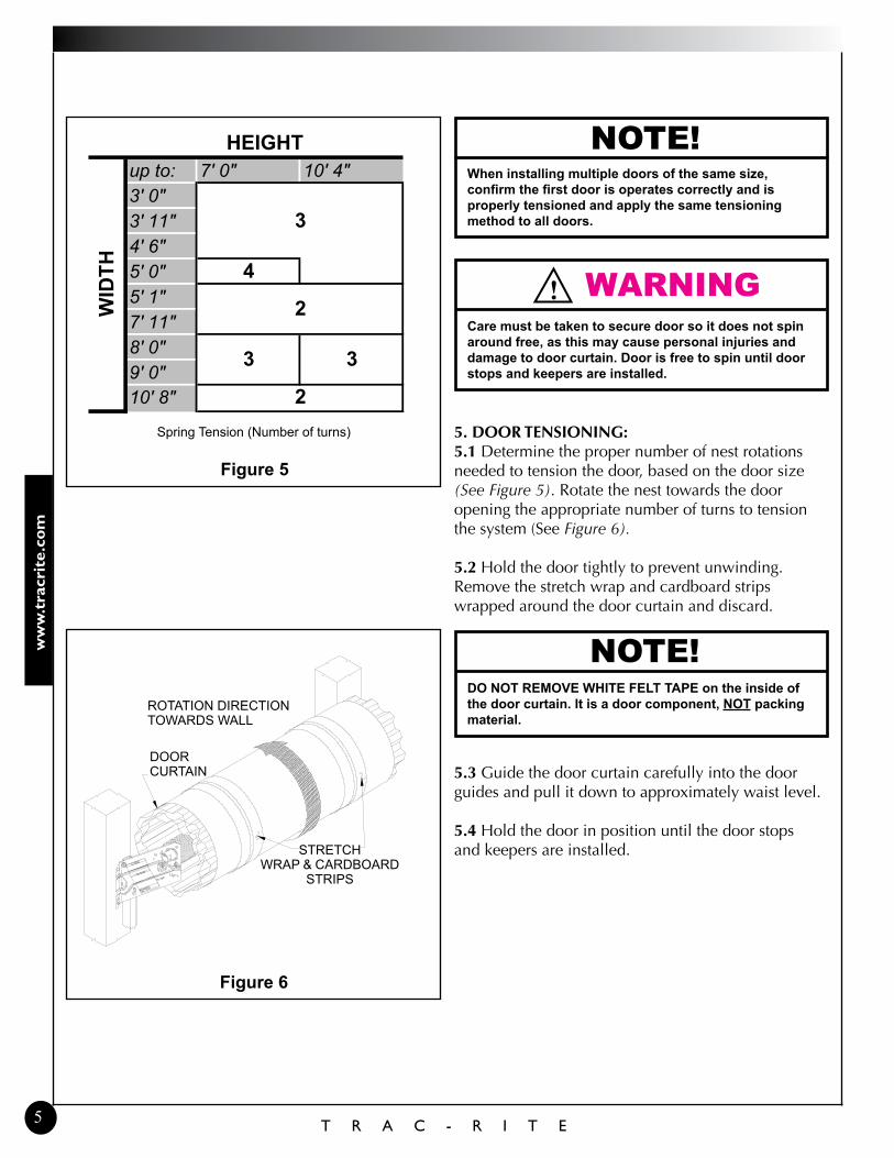
NOTE!When installing multiple doors of the same size, confirm the first door is operates correctly and is properly tensioned and apply the same tensioning method to all doors.
WARNING!Care must be taken to secure door so it does not spin around free, as this may cause personal injuries and damage to door curtain. Door is free to spin until door stops and keepers are installed.
5. DooR teNSIoNING:5.1 Determine the proper number of nest rotations needed to tension the door, based on the door size (See Figure 5). Rotate the nest towards the door opening the appropriate number of turns to tension the system (See Figure 6).
5.2 Hold the door tightly to prevent unwinding. Remove the stretch wrap and cardboard strips wrapped around the door curtain and discard.
NOTE!DO NOT REmOVE WHITE FElT TAPE on the inside of the door curtain. It is a door component, NOT packing material.
5.3 Guide the door curtain carefully into the door guides and pull it down to approximately waist level.
5.4 Hold the door in position until the door stops and keepers are installed.
Figure 6
5
up to: 7' 0" 10' 4"3' 0"3' 11"4' 6"5' 0" 45' 1"7' 11"8' 0"9' 0"10' 8" 2
WID
TH
HEIGHT
3
2
3 3
Spring Tension (Number of turns)
Figure 5
DOOR CURTAIN
STRETCH wRAP & CARDBOARD
STRIPS
ROTATION DIRECTION TOwARDS wALL

800-448-8979
T R A C - R I T E
7. SeCURING tHe GUIDeS7.1 Pull the door down to within 6” of the floor (See Figure 8). Adjust the door guides so there is 1/8” to 1/4” of play side to side. if the clearance is too small the door will be hard to operate. too much clearance will allow the door to move side to side excessively and may cause the door to bind.
7.2 Attach the guides to the jambs as follows:
7.2a For steel jambs, secure with supplied tek screws, using one fastener per mounting hole.
7.2b For wood jambs, secure with supplied lag bolts, using one fastener per mounting hole.
7.2c For masonry jambs, install masonry clips along the guide height, using one clip located next to each mounting hole on the guide. Make sure the clips are flush with the back of the guide. Attach each clip to the guide with two (2) small (#12-14 x 3/4”) supplied Tek screws (See Figure 8). Drill a hole in the masonry and fasten the clip in place using supplied anchors.
WARNING!Immediately install keepers and door stops. These devices will prevent the door from rolling up out of the guides and possibly causing injury.
! CAUTIONExcessive force in operation may cause damage to the door. If the door binds, adjust guides to allow appropriate movement.
Figure 7
6. KeePeR AND toP StoP ASSeMBLY6.1 Remove whiz nut from each side of door bottom bar (See Figure 7).
6.2 Attach one keeper to the bottom interior edge of each side of the door with one (1) 1/4” carriage bolt and whiz nut that was just removed. On doors with two handles, install one of the handles as you install the left side keeper (See Figure 10).
6.3 tighten whiz nuts to fasten keepers.
6.4 slide the stops up into position so that the hook tab mates with the upper hole on the stop (See Figure 7). Fasten each door stop to each bracket as shown using one (1) 5/16” track bolt and nut through the lower hole of the stop.
6
BENT CURTAIN LEAD IN
DOOR BRACKET
DOOR STOP 5/16” TRACK BOLT & NUT
DOOR GUIDE
KEEPER1/4” CARRIAGE BOLT & NUT
BOTTOM OF DOOR CURTAIN
DOOR AXLE ASSEMBLY NOT SHOWN FOR CLARITY
Figure 8
NON-MASONRY FASTENING HOLES
MASONRY ANCHORMASONRY CLIP
TEK SCREwS #12-14 x 3/4”
MAINTAIN 1/8 TO 1/4” GAP (3-6MM) BETwEEN GUIDE AND wEAR GUARD
DOOR CURTAIN
DOOR GUIDE
BLOCK JAMB

ww
w.t
racr
ite.
com
T R A C - R I T E
Figure 11
8.3 Attach the guide warning label (See Figure 11) to wall next to the guide at eye level. If mounting to an unfinished surface such as bare masonry or wood, attach the label to a nonporous surface and use mechanical fasteners to mount on wall.
8. FINAL ASSeMBLY8.1 Pull rope handle: tie a knot in one end of the rope. slide the plastic handle onto the rope and pull the knot up into the handle. Pass the other end of the rope through the hole in the center of the bottom edge of the door and tie another knot in the end to keep the rope from pulling through (See Figure 9).
Figure 10
8.2 Exterior handle: Attach the handle(s) to the bottom exterior edge of the door with two (2) 1/4” carriage bolts and whiz nuts provided (See Figure 10). Doors 8’ wide and larger will have two handles.
Figure 9
7
PULL ROPE HANDLE
EXTERIOR HANDLE
BOTTOM ASSEMBLY

800-448-8979
T R A C - R I T E
9. ADJUStING DooR SPRING teNSIoN9.1 A properly tensioned door should be balanced (does not fall closed or spring open) when opened to waist level. step on the handle to close door fully.
9.2 to add tension, insert winding bar in the rectangular hole in the tension wheel and pull down until ratchet clicks. Move up slightly until ratchet locks in place (See Figure 12). if more tension is needed, move winding bar to the next hole in the tension wheel and repeat as necessary.
9.3 to remove tension, insert winding bar into tension wheel and move down 1” to unlock ratchet. Push the tension lock pin toward wall and raise winding bar 2”. Release tension lock pin. Move up 1/8 turn until the ratchet locks in place.
9.4 if door has two tensioners be sure to equally add or remove tension to each side of door.
10. oPtIoNAL FIeLD INStALLeD DRAFt StoP oR BRUSH SeAL10.1 Close the door before installing the draft stop. Note that with the door down, the curtain may “bow” slightly near the top; this bowing is normal. For the draft stop to be effective, it should follow the “bow” in the door curtain so that it stays in contact across the entire width of the door curtain. starting at one end, attach to header every 9” with appropriate fasteners. If necessary, trim excess at other end.
10.2 Close the door before installing the brush seal. Position brush seal so it just touches the flat portion of the inside of the curtain (See Figure 13). Fasten brush seal to jamb every 12” with appropriate fasteners.
Figure 13
8
Components under extreme spring tension can cause SERIOUS INJURY or DEATH. Adjustments and repairs must be made by a qualified door mechanic using proper tools and instructions. Do NOT attempt to adjust door tension unless the door is in the “UP” position. Winding bar should be solid steel 1/2” diameter rod or 3/8” x 1/2” flat.
WARNING!
TENSION LOCK PIN
wINDING BAR
MORE TENSION
LESS TENSIONTENSION
wHEEL
DOOR JAMB
BRUSH SEAL
CURTAINDOOR GUIDE
Figure 12
CAUTION!Spring Tension is Critical: Improper tensioning of the spring(s) can result in door damage and reduce the life of your door. The door should not slam up or down during operation. No warranty claims will be honored due to damage caused by improperly tensioned spring(s).
ww
w.t
racr
ite.
com
T R A C - R I T E
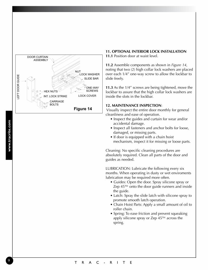
11. oPtIoNAL INteRIoR LoCK INStALLAtIoN11.1 Position door at waist level.
11.2 Assemble components as shown in Figure 14, noting that two (2) high collar lock washers are placed over each 1/4” one-way screw to allow the lockbar to slide freely.
11.3 As the 1/4” screws are being tightened, move the lockbar to assure that the high collar lock washers are inside the slots in the lockbar.
12. MAINteNANCe INSPeCtIoN: Visually inspect the entire door monthly for general cleanliness and ease of operation.
• Inspect the guides and curtain for wear and/or accidental damage.
• Inspect all fasteners and anchor bolts for loose, damaged, or missing parts.
• If door is equipped with a chain hoist mechanism, inspect it for missing or loose parts.
Cleaning: No specific cleaning procedures are absolutely required. Clean all parts of the door and guides as needed. LUBRICATION: Lubricate the following every six months. when operating in dusty or wet enviroments lubrication may be required more often.
• Guides: Open the door. Spray silicone spray or Zep 45™ onto the door guide runners and inside the guide.
• Latch: Spray the slide latch with silicone spray to promote smooth latch operation.
• Chain Hoist Parts: Apply a small amount of oil to roller chain.
• Spring: To ease friction and prevent squeaking apply silicone spray or Zep 45™ across the spring.
9
Figure 14
DOOR CURTAIN ASSEMBLY
LEFT
DO
OR
GU
IDE
CARRIAGE BOLTS
INT. LOCK STRIKE
HEX NUTS
NUTLOCK wASHER
SLIDE BAR
ONE-wAY SCREwS
LOCK COVER

800-448-8979
T R A C - R I T E
Doo
r Ass
embl
y - P
arts
lay
out
10

PHONE 800 448 8979FAX 800 236 8722wEbsitE www.tracrite.comEMAiL [email protected] ADDREss 314 wilburn Road sun Prairie, wi 53590
522000 rev H (04/12)© Trac-Rite
Proprietary Noticeinformation contained in this document is copyrighted by trac-Rite and may not be duplicated in full or part by any person without prior written approval of trac-Rite. its purpose is to provide the user with adequate detailed documentation to efficiently install a model 944 rolling curtain door.