Rolling Contact Fatigue - EPS Personal home...
16
Name /bam_asmint_104738/6072_006e1/Mp_1 07/12/2002 03:37PM Plate # 0 pg 1 # Rolling Contact Fatigue R. Ahmed, Heriot-Watt University (United Kingdom) Fig. 1 Typical morphology of fatigue spall in rolling- element bearings. (a) Fatigue spall centered on a ball bearing raceway. (b) Fatigue spall on 12.7 mm (0.5 in.) diameter steel ball obtained using rolling four-ball machine A MAJOR CAUSE of failure in components subjected to rolling or rolling/sliding contacts (e.g., rolling-contact bearings, gears, and cam/ tappet arrangements) is contact fatigue. Rolling- contact fatigue (RCF) can be defined as the mechanism of crack propagation caused by the near-surface alternating stress field within the rolling-contact bodies, which eventually leads to material removal. The mechanism of RCF thus differs from the delamination theory of wear (Ref 1, 2), which also relies on cyclic loading but in sliding conditions and at asperity level. The alternating stress field in RCF is either in pure rolling (e.g., rolling-element bearings), or in rolling/sliding conditions (e.g., gear-tooth loading), depending on the absence or presence of gross sliding within the rolling-contact region. Microslip (e.g., Heathcote or Reynolds slip [Ref 3]) within the contact region is, however, inevi- table in both pure rolling and rolling/sliding con- ditions. The term “RCF” in this article, however, refers to pure rolling configurations, except where specific references to rolling/sliding con- ditions are made. The material removal in a RCF failure varies from micropitting, macropitting and spalling (Ref 4–5) in conventional bearing steels (Fig. 1) to delamination in hybrid ceramics (Ref 6) and overlay coatings (Ref 7), as discussed later. Con- tact geometry of the bodies subjected to RCF can be conforming (e.g., contact between the outer race and roller in a rolling-element roller bear- ing) or nonconforming (e.g., contact between the inner race and roller in a rolling-element roller bearing). The alternating stress field responsible for RCF failure can generally be idealized from Hertzian contact conditions in conventional me- tallic and ceramic materials (e.g., bearing steel and, Si 3 N 4 ceramics), but the interpretation of stress fields needs to be cautiously approached when dealing with layered surfaces (e.g., overlay coatings). The preliminary focus in this article is on RCF of coated surfaces, although the stress field conditions are briefly reviewed for the RCF of a homogenous material surface. Prediction of statistical fatigue life (Ref 8–10) and failure modes (Ref 4, 11–17) during RCF in conventional bearing steels also has been the fo- cus of hundreds of papers and numerous books (Ref 18–20) in published literature. The scope of this article focuses principally on the RCF per- formance and failure modes of overlay coatings, such as those deposited by physical vapor de- position, chemical vapor deposition, and thermal spraying. Some background description of RCF in bearing steels is, however, useful and neces- sary, because RCF of steels is important. General background on RCF in bearing steels also helps develop an understanding of failure modes in overlay coatings discussed in this article. More detailed description of RCF in conventional bearing steels can be seen elsewhere (e.g., Ref 11–17), along with a general discussion of con- tact fatigue in the article “Fatigue Failures” in this Volume. General Principles of RCF General Background. The origin of RCF failure is understood to be stress concentrations, which initiate and propagate fatigue crack under cyclic loading. These stress concentrations occur due to surface or subsurface stress risers or to the geometry and kinematics of the contacting pair. Figure 2 summarizes a list of these stress risers, which have been the subject of numerous sci- entific investigations that have resulted in the improved life of rolling-element bearings (Ref 11). With the introduction of cleaner steels and greater precision in the manufacture of bearings, most of the surface and subsurface stress risers listed in Fig. 2 have been addressed. Neverthe- less, the demand to operate rolling-element bear- ings in harsh tribological environments of lubri- cation, load, contamination, and temperature push for higher fatigue limits, and thus call for improved understanding of the RCF failure modes. Four distinct failure modes have been estab- lished in rolling-contact bearings (Ref 5). These classifications include wear-type failures, plastic flow, contact fatigue, and bulk failures. Although the aim of this article is to comprehend RCF fail- ures, wear-type failures that include surface re- moval and material transfer do not form a part of this background; Blau (Ref 13) has given a detailed account of rolling-contact wear (RCW), and he differentiates between RCF and RCW in the sense that RCF is a damage accumulation process under cyclic loading, whereas, RCW can be thought of as nucleation sites for initiating fatigue damage. Rolling-contact wear is thus critical in components operating in rolling-slid- ing contact (e.g., gears where the lubrication re- gime is either boundary or mixed). However, the full film lubrication generally seen in rolling-ele- ment bearings should prevent such damage, ex- cept at the start/stop of rolling motion. Similarly, plastic flow and bulk failure depend on the bulk thermal and mechanical properties of the bearing materials and can lead to permanent dimensional changes. The most classical failure mode in rolling- contact components is RCF. Rolling-contact fa- tigue failure modes have previously been clas-
Transcript of Rolling Contact Fatigue - EPS Personal home...

Name /bam_asmint_104738/6072_006e1/Mp_1 07/12/2002 03:37PM Plate # 0 pg 1 #
Rolling Contact FatigueR. Ahmed, Heriot-Watt University (United Kingdom)
Fig. 1 Typical morphology of fatigue spall in rolling-element bearings. (a) Fatigue spall centered on a
ball bearing raceway. (b) Fatigue spall on 12.7 mm (0.5 in.)diameter steel ball obtained using rolling four-ballmachine
A MAJOR CAUSE of failure in componentssubjected to rolling or rolling/sliding contacts(e.g., rolling-contact bearings, gears, and cam/tappet arrangements) is contact fatigue. Rolling-contact fatigue (RCF) can be defined as themechanism of crack propagation caused by thenear-surface alternating stress field within therolling-contact bodies, which eventually leads tomaterial removal. The mechanism of RCF thusdiffers from the delamination theory of wear(Ref 1, 2), which also relies on cyclic loadingbut in sliding conditions and at asperity level.The alternating stress field in RCF is either inpure rolling (e.g., rolling-element bearings), orin rolling/sliding conditions (e.g., gear-toothloading), depending on the absence or presenceof gross sliding within the rolling-contact region.Microslip (e.g., Heathcote or Reynolds slip [Ref3]) within the contact region is, however, inevi-table in both pure rolling and rolling/sliding con-ditions. The term “RCF” in this article, however,refers to pure rolling configurations, exceptwhere specific references to rolling/sliding con-ditions are made.
The material removal in a RCF failure variesfrom micropitting, macropitting and spalling(Ref 4–5) in conventional bearing steels (Fig. 1)to delamination in hybrid ceramics (Ref 6) andoverlay coatings (Ref 7), as discussed later. Con-tact geometry of the bodies subjected to RCF canbe conforming (e.g., contact between the outerrace and roller in a rolling-element roller bear-ing) or nonconforming (e.g., contact between theinner race and roller in a rolling-element rollerbearing). The alternating stress field responsiblefor RCF failure can generally be idealized fromHertzian contact conditions in conventional me-tallic and ceramic materials (e.g., bearing steeland, Si3N4 ceramics), but the interpretation ofstress fields needs to be cautiously approachedwhen dealing with layered surfaces (e.g., overlaycoatings). The preliminary focus in this article ison RCF of coated surfaces, although the stressfield conditions are briefly reviewed for the RCFof a homogenous material surface.
Prediction of statistical fatigue life (Ref 8–10)and failure modes (Ref 4, 11–17) during RCF inconventional bearing steels also has been the fo-cus of hundreds of papers and numerous books(Ref 18–20) in published literature. The scope ofthis article focuses principally on the RCF per-
formance and failure modes of overlay coatings,such as those deposited by physical vapor de-position, chemical vapor deposition, and thermalspraying. Some background description of RCFin bearing steels is, however, useful and neces-sary, because RCF of steels is important. Generalbackground on RCF in bearing steels also helpsdevelop an understanding of failure modes inoverlay coatings discussed in this article. Moredetailed description of RCF in conventionalbearing steels can be seen elsewhere (e.g., Ref11–17), along with a general discussion of con-tact fatigue in the article “Fatigue Failures” inthis Volume.
General Principles of RCF
General Background. The origin of RCFfailure is understood to be stress concentrations,which initiate and propagate fatigue crack undercyclic loading. These stress concentrations occurdue to surface or subsurface stress risers or to thegeometry and kinematics of the contacting pair.Figure 2 summarizes a list of these stress risers,which have been the subject of numerous sci-entific investigations that have resulted in theimproved life of rolling-element bearings (Ref11). With the introduction of cleaner steels andgreater precision in the manufacture of bearings,most of the surface and subsurface stress riserslisted in Fig. 2 have been addressed. Neverthe-less, the demand to operate rolling-element bear-ings in harsh tribological environments of lubri-cation, load, contamination, and temperaturepush for higher fatigue limits, and thus call forimproved understanding of the RCF failuremodes.
Four distinct failure modes have been estab-lished in rolling-contact bearings (Ref 5). Theseclassifications include wear-type failures, plasticflow, contact fatigue, and bulk failures. Althoughthe aim of this article is to comprehend RCF fail-ures, wear-type failures that include surface re-moval and material transfer do not form a partof this background; Blau (Ref 13) has given adetailed account of rolling-contact wear (RCW),and he differentiates between RCF and RCW inthe sense that RCF is a damage accumulationprocess under cyclic loading, whereas, RCW canbe thought of as nucleation sites for initiating
fatigue damage. Rolling-contact wear is thuscritical in components operating in rolling-slid-ing contact (e.g., gears where the lubrication re-gime is either boundary or mixed). However, thefull film lubrication generally seen in rolling-ele-ment bearings should prevent such damage, ex-cept at the start/stop of rolling motion. Similarly,plastic flow and bulk failure depend on the bulkthermal and mechanical properties of the bearingmaterials and can lead to permanent dimensionalchanges.
The most classical failure mode in rolling-contact components is RCF. Rolling-contact fa-tigue failure modes have previously been clas-
Name /bam_asmint_104738/6072_006e1/Mp_2 07/12/2002 03:37PM Plate # 0 pg 2 #
2 / Wear Failures
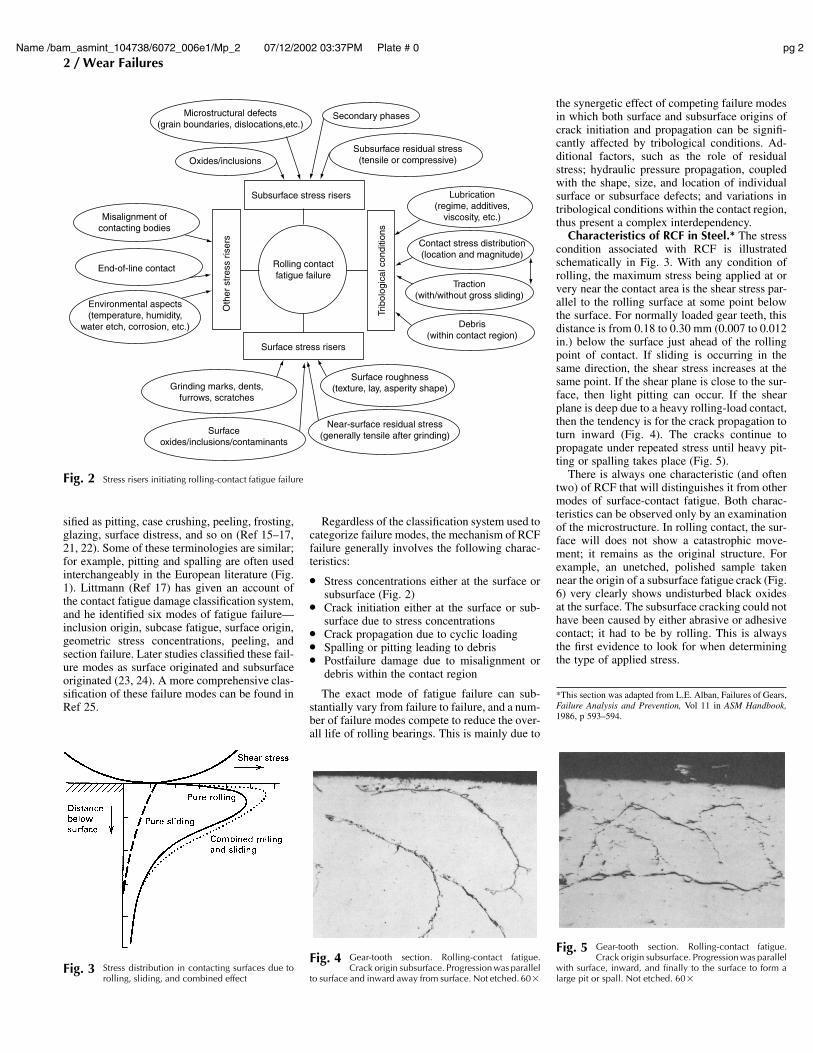
Fig. 3 Stress distribution in contacting surfaces due torolling, sliding, and combined effect
Microstructural defects(grain boundaries, dislocations,etc.)
Secondary phases
Oxides/inclusionsSubsurface residual stress
(tensile or compressive)
Misalignment ofcontacting bodies
End-of-line contact
Environmental aspects(temperature, humidity,
water etch, corrosion, etc.)
Lubrication(regime, additives,
viscosity, etc.)
Contact stress distribution(location and magnitude)
Traction(with/without gross sliding)
Debris(within contact region)
Surface roughness(texture, lay, asperity shape)
Near-surface residual stress(generally tensile after grinding)
Grinding marks, dents,furrows, scratches
Surfaceoxides/inclusions/contaminants
Subsurface stress risers
Surface stress risers
Oth
er s
tres
s ris
ers
Trib
olog
ical
con
ditio
ns
Rolling contactfatigue failure
Fig. 2 Stress risers initiating rolling-contact fatigue failure
Fig. 4 Gear-tooth section. Rolling-contact fatigue.Crack origin subsurface. Progression was parallel
to surface and inward away from surface. Not etched. 60�
Fig. 5 Gear-tooth section. Rolling-contact fatigue.Crack origin subsurface. Progression was parallel
with surface, inward, and finally to the surface to form alarge pit or spall. Not etched. 60�
sified as pitting, case crushing, peeling, frosting,glazing, surface distress, and so on (Ref 15–17,21, 22). Some of these terminologies are similar;for example, pitting and spalling are often usedinterchangeably in the European literature (Fig.1). Littmann (Ref 17) has given an account ofthe contact fatigue damage classification system,and he identified six modes of fatigue failure—inclusion origin, subcase fatigue, surface origin,geometric stress concentrations, peeling, andsection failure. Later studies classified these fail-ure modes as surface originated and subsurfaceoriginated (23, 24). A more comprehensive clas-sification of these failure modes can be found inRef 25.
Regardless of the classification system used tocategorize failure modes, the mechanism of RCFfailure generally involves the following charac-teristics:
● Stress concentrations either at the surface orsubsurface (Fig. 2)
● Crack initiation either at the surface or sub-surface due to stress concentrations
● Crack propagation due to cyclic loading● Spalling or pitting leading to debris● Postfailure damage due to misalignment or
debris within the contact region
The exact mode of fatigue failure can sub-stantially vary from failure to failure, and a num-ber of failure modes compete to reduce the over-all life of rolling bearings. This is mainly due to
the synergetic effect of competing failure modesin which both surface and subsurface origins ofcrack initiation and propagation can be signifi-cantly affected by tribological conditions. Ad-ditional factors, such as the role of residualstress; hydraulic pressure propagation, coupledwith the shape, size, and location of individualsurface or subsurface defects; and variations intribological conditions within the contact region,thus present a complex interdependency.
Characteristics of RCF in Steel.* The stresscondition associated with RCF is illustratedschematically in Fig. 3. With any condition ofrolling, the maximum stress being applied at orvery near the contact area is the shear stress par-allel to the rolling surface at some point belowthe surface. For normally loaded gear teeth, thisdistance is from 0.18 to 0.30 mm (0.007 to 0.012in.) below the surface just ahead of the rollingpoint of contact. If sliding is occurring in thesame direction, the shear stress increases at thesame point. If the shear plane is close to the sur-face, then light pitting can occur. If the shearplane is deep due to a heavy rolling-load contact,then the tendency is for the crack propagation toturn inward (Fig. 4). The cracks continue topropagate under repeated stress until heavy pit-ting or spalling takes place (Fig. 5).
There is always one characteristic (and oftentwo) of RCF that will distinguishes it from othermodes of surface-contact fatigue. Both charac-teristics can be observed only by an examinationof the microstructure. In rolling contact, the sur-face will does not show a catastrophic move-ment; it remains as the original structure. Forexample, an unetched, polished sample takennear the origin of a subsurface fatigue crack (Fig.6) very clearly shows undisturbed black oxidesat the surface. The subsurface cracking could nothave been caused by either abrasive or adhesivecontact; it had to be by rolling. This is alwaysthe first evidence to look for when determiningthe type of applied stress.
*This section was adapted from L.E. Alban, Failures of Gears,Failure Analysis and Prevention, Vol 11 in ASM Handbook,1986, p 593–594.

Name /bam_asmint_104738/6072_006e1/Mp_3 07/12/2002 03:37PM Plate # 0 pg 3 #
Rolling Contact Fatigue / 3
Fig. 7 Same sample as in Fig. 6, showing details of sub-microstructure called butterfly wings. 3% nital
etch. (a) 125�. (b) 310�
Fig. 6 Gear-tooth section. Rolling-contact fatigue dis-tinguished by subsurface shear parallel to sur-
face. Note the undisturbed black oxides at the surface, in-dicating no surface-material movement. Not etched. 125�
The second characteristic is common only ina martensitic steel that contains very little or noaustenite and is found only at, along, or in linewith the shear plane. This is a microstructuralfeature that has been termed “butterfly wings.”If the sample in Fig. 6 is etched properly with3% nital, the result is the microstructure shownin Fig. 7(a). Increasing the magnification to310� shows more detail (Fig. 7b). This type ofmicrostructural alteration is typically associatedwith an inclusion present, but not always. Exten-sive and very detailed studies of RCF refer to thegray substructure as white bands of altered mar-tensite. It is believed that these substructures arecaused when, under an extreme shearing stress,movement is called for but is restrained and con-tained to such an extent that the energy absorbedinstitutes a change in the microstructure aheadof a progressing crack. They are never observedwhen significant amounts of austenite are pres-ent; austenite quickly absorbs the energy and isconverted to untempered martensite. They arealso in an area that has not been deformed buthas definitely been transformed. Each area hasdistinct boundaries, and the oncoming cracks ap-pear to follow these boundaries. It has beennoted that some academic studies refer to thissame structure as being a transformed shear bandproduct formed by adiabatic shear. A more de-tailed review of microstructural change in con-tact fatigue of steel is provided in the article“Contact Fatigue of Hardened Steel” in ASMHandbook, Volume 19, Fatigue and Fracture(Ref 11).
Rolling-Contact Fatigue Testing. The afore-mentioned complexity in underpinning the exactfailure mechanism has led to simplified experi-mental contact model configurations (RCF tri-bometers), which have been extensively used toinvestigate the influence of changes in bearingmaterials, residual stress, and tribological con-ditions. Although the correlation between the fa-tigue life of these model contact configurationsand the actual life of bearings in service has notbeen satisfactorily achieved, these RCF tribom-eters serve three important functions:
● They provide a method to benchmark the per-formance of existing and new generation ofbearing materials prior to full-scale testing.
● They provide an insight to the mechanisms ofindividual failure modes by allowing the flex-ibility to vary individual parameters, such aslubrication, material cleanliness, contact load,surface roughness, and so on.
● Progressive tests allow the possibility to cat-alog the history of specific failures, therebyindicating the boundaries of failure initiationand propagation either in terms of progressivefailure morphology or vibration levels, whichcan be useful for condition monitoring andwear mapping.
Although the failure mode depends on the tri-bological conditions selected for individual in-vestigation, some test conditions adopted in RCFtribometers can accelerate the RCF failure, forexample, by either increased contact loading or
increased rolling velocity. This alters the elastic/plastic (shakedown) response, lubrication re-gime, and kinematics within the contact regionwhen compared with those in the actual rolling-contact bearings. These variations can thus influ-ence the mechanism of fatigue failure, and re-sults of such investigations need to be interpretedin accordance with the adapted test conditions.Various researchers have compared the under-pinning failure mechanisms observed during ac-celerated testing versus field performance. Theinfluence of higher contact pressure on the resid-ual stress profile and changes in white bands areconsidered in Ref 26. The elastic plastic shake-down can be thought responsible for changesthat influences both the microstructure and alsoresidual stress profile. Results have indicatedthat martensitic decay is possible for long dura-tion tests and high toughness of bearing materialof acceptable hardness leads to high RCF life inboth accelerated and field tests.
The correct choice of tribometer is also criticalfor a given application. For example, a four-ballmachine can simulate the kinematics of a deep-groove rolling-element ball bearing; however,the model contact in this tribometer considers anonconforming contact between the inner raceand rolling-element ball, which is not the case inan actual bearing. The capabilities of variousRCF testing methods have been tabulated (Table1) to compare the features of 13 different RCFtribometers (Ref 13). These tribometers (Ref 26,27) have the capability to vary tribological con-ditions, for example, lubrication regime, contactconfiguration, and roll-to-slip ratio to mimicpure rolling or rolling/sliding motion for variousrolling-contact applications. Even within a givencategory of RCF testers, there are generally nu-merous combinations of test configurations to al-low the flexibility in experimental design; for ex-ample, in a rolling four-ball tester, there arenumerous configurations (type I, II, III) possibleto vary ball kinematics (Ref 28). Another mod-ification to RCF testing has been the investiga-tions of artificially induced surface defects (Ref29, 30), which are thought to act as crack initi-ation sites during the RCF failure. Such inves-
tigations are useful in understanding the influ-ence of surface defects on RCF failure and mayalso reduce the RCF testing time; the relevanceof such investigations to the tribological condi-tions and failure modes in real bearing applica-tions, however, requires a careful considerationof the differences in tribological conditions be-tween them.
Theories of RCF Failure. The exact mecha-nism of RCF failure in engineering componentsneeds to be appreciated in view of tribologicalconditions and various crack initiation and prop-agation sites; nevertheless, various theories (dis-cussed subsequently) linking the location andmagnitude of cyclic tensile or shear stress com-ponents to RCF failure are useful in understand-ing the failure mechanism. Although such theo-ries based on cyclic stress components of theHertzian stress field can sometimes oversimplifythe RCF failure mechanism, the microscopic in-vestigations comparing the cyclic stress com-ponents to RCF failure are compelling. For ex-ample, the existence of subsurface etchings andbutterflies have been related to shear stress com-ponents under the contact surface (Ref 5, 11, 14,15, 17).
Figure 8 illustrates a two-dimensional sche-matic of the location and magnitude of maxi-mum shear (smax), orthogonal shear (qorth) andmaximum tensile (Tmax) stress for a circular, dry-rolling frictionless contact. The contact diameteris assumed to be 2a, and smax has a maximumvalue vertically below the center of contact re-gion in a plane inclined at 45� to the coordinateaxis (Ref 11). Its magnitude at any point can becalculated using the equation:
smax � (r1 � r3)/2 � 0.35Po (Eq 1)
where r1 and r3 are the values of maximum andminimum principal stress, respectively, and Po is

Name /bam_asmint_104738/6072_006e1/Mp_4 07/12/2002 03:37PM Plate # 0 pg 4 #
4 / Wear Failures
Table 1 Summary of RCF testing methods
Method Description Ref
NASA five-balltesting apparatus
Four lower balls, freely rotation 90� apart in a separator; simulates the kinematics of a thrust-loaded bearing; the contact angle can be varied; vibration sensor detects failure inunattended tests; low- (cryo) and high-temperature testing (to 1000 �C, or 1830 �F)
26 (a)
Flat-washer testingapparatus
16 retained balls rolling in a circle on a flat washer with a 75 mm (3 in.) outside diameter,50 mm (2 in.) bore, and 6.4 mm (1⁄4 in.) thickness; 4.17 GPa (605 ksi) contact stress; 1500rpm; filtered lubricant delivery system; piezo sensor detects vibration
26 (b)
Unisteel testingapparatus
Flat washer on retained balls; hanging dead-weight load; contact stress approximately 4.5GPa (650 ksi); 1500 rpm; drip feed of lubricant; vibration detection system; thermocouplesmonitor temperature (typically 50 to 60 �C, or 120 to 140 �F)
26 (c)
Rolling-contacttesting apparatus
Two hemispherically ground, toroidal rollers loaded against a round bar; 40:1 ratio of rollerdiameter to bar diameter; 2.7 to 5.5 GPa (390 to 800 ksi) contact stress; 12,500 rpm; drip-feed lubrication; velocity-vibration sensor
26 (d)
Ball-rod testingapparatus(Federal-Mogul)
Three 12.5 mm (1⁄2 in.) balls loaded against a rotating 9.5 mm (3⁄8 in.) outside diameter centerrod; 3600 rpm; spring load on opposing tapered retaining rings; accelerometer coupledwith a shutdown device; drip-feed lubrication; stress per ball typically 6 GPa (870 ksi)
26 (e)
Cylinder-to-balltesting apparatus
Symmetrical arrangement of two 19 mm (3⁄4 in.) balls rolling on a 12.5 mm (1⁄2 in.) outsidediameter captive cylinder; coiled-spring load through a multiplying lever; small cylinderrpm � 22,677; splash lubrication; maximum contact stress, 5.8 GPa (840 ksi)
26 (f)
Cylinder-to-cylindertesting apparatus
Symmetrical arrangement of two 12.5 mm (1⁄2 in.) cylinders on two 20 mm (0.8 in.) outsidediameter captive cylinders; coiled-spring load through a multiplying lever; small cylinder,cpm � 20,400; splash lubrication; maximum contact stress less than 4.4 GPa (640 ksi);vibration sensor terminates test
26 (g)
Ring-on-ring testingapparatus
Crowned rings rolling on their peripheries; ring diameters of 50 and 53 mm (2 and 2.1 in.)provide “no-slip” condition, but various degrees of slip are possible by changing ringdiameters; typically 2000 rpm; contact ratio measured by electrical resistance; contactstress range typically 0.98 to 3.9 GPa (140 to 570 ksi)
26 (h)
Various types Method of testing for rolling contact fatigue of bearing steels 26 (i)Multiple bearing
testing apparatusDeep-groove ball bearing design; typically 3000 rpm; four bearings on a single center shaft;
maximum contact stress, 2.9 GPa (420 ksi); accelerometers on the outer housing monitorfailure
26 (j)
Rolling four-balltesting apparatus
Top ball drives three lower balls in a tetragonal arrangement; lower balls free to rotate in thecup; all balls 12.5 (1⁄2 in.) diam; upper balls spindle speed, 1500 rpm; 5.9 kN (1325 lbf)load applied vertically
26 (k)
High-speed four-balltesting apparatus
Same arrangement as above, but speeds of 15,000 to 20,000 rpm; operating temperaturesoften exceed 100 �C (210 �F) (Plint machine)
26 (k)
“AOL” verticaltesting apparatus
11 retained balls clamped between two flat washers; thrust load; recirculating lubricantsystem
26 (k)
Inclined ball-on-disktesting apparatus
Spindle-held 20.5 mm (0.8 in.) ball rolling on a disk; up to 800 �C (1470 �F); ball speed upto 7200 rpm; disk speed up to 3600 rpm; variable slide/roll ratios; traction measurements;designed for ceramics
27
Further information can be found on the following pages of Ref 26: (a) p 5–45, (b) p 46–66, (c) p 67–84, (d) p 85–106, (e) p 107–124, (f) p 125–135, (g) p 136–149, (h) p 150–165, (i) p 169–189, (j) p 206–218, (k) p 219–236. Source Ref 13.
Note: NASA, National Aeronautics and Space Administration
2a
Po
Maximum shear stress (τ)(inclined at 45° plane)
Orthogonal shear stress (qorth)(acting on orthogonal plane)
qorth(min) τmax
qorth(max)
qorthqorth
Negative shear Positive shear
Y
Z
Zorth(max)
≅0.35a Zτ(max)
≅0.48a
Tmax = (1–2v)Po3
(acting on the surface)
Fig. 8 Two-dimensional schematic of variation in critical stress components with depth for a circular rolling contactof diameter 2a
the peak compressive stress (Hertzian stress).Similarly, the orthogonal shear stress (qorth) actson planes parallel and perpendicular to the sur-face and is the vector sum of qyz and qzy for acircular contact, that is:
q q q Pyz zxorth o= + =2 2 0 21( ) . (Eq 2)
where x and y are the two axes of the contactcircle. For elliptical contacts, x any y indicate themajor and minor axes of the contact ellipse. Al-though the magnitude of orthogonal shear stressis the same at the leading and trailing edge ofthe contact region for a dry, frictionless contact,the direction is reversed to give rise to maximumqorth(max) and minimum qorth(min) values of or-thogonal shear stress (Fig. 8). Hence, the maxi-mum amplitude of orthogonal shear stress re-versal, Dqorth, is given as:
Dqorth � (qorth(max) � qorth(min)) � 0.42Po (Eq 3)
Values relative to Po indicated in Eq 1–3 willbe different for elliptical contacts. Also, the lo-cation and magnitude of these stresses stronglydepend on the value of the friction coefficientwithin the contact region. As the friction coef-ficient increases, the tangential loading shifts thelocation of maximum shear stress toward the sur-face. Similarly, the lubrication regime, surfaceroughness, and residual stress all affect the stressfields. Engineering Science Data Units (Ref 31,32) tabulate the variation in these stress fieldswith friction coefficient and contact ellipse ratio.
Both maximum and orthogonal shear stresstheories have been proposed to act as the sub-surface failure modes during RCF. Fatigue lifeprediction theories, for example, the Lundberg-Palmgren theory (Ref 33), is also associated withthe location of orthogonal shear stress. More re-cently, equivalent or effective shear stress (qe)based upon the von Mises criteria (Ref 32–34)has been shown to support experimental inves-tigations, that is:
q q q qe xy yz zx
x y z x z x
= + +
+ − + − + −
2 2 2
16
2 2 21 2
( ) ( ) ( ){ }
σ σ σ σ σ σ
(Eq 4)
where rx, ry, and rz are the direct stress, and qxy,qyz, and qzx are the shear stress values, respec-tively. This failure criterion for homogenous,isotropic, and ductile materials can be related tothe critical value of effective shear stress (qe(crit))using the relation:
qe ycrit yield2
( ) = =σ τ3 2(Eq 5)
where ryield is the yield strength of material inuniaxial tension or compression, and sy is theyield stress in simple shear (Ref 32). Apart fromthe subsurface shear stress and von Mises criteriamentioned previously, maximum tensile (Tmax)
stress criteria is a useful indicator for appreciat-ing RCF failure mechanism in brittle materials.It is postulated that cracks initiate and propagate
from the tensile stress at the edge of the contactregion (Fig. 8). The magnitude of Tmax increaseswith the increase in friction coefficient; however,
Name /bam_asmint_104738/6072_006e1/Mp_5 07/12/2002 03:37PM Plate # 0 pg 5 #
Rolling Contact Fatigue / 5
its location remains very near the surface. For africtionless, dry contact, the value of Tmax can beapproximated using the relation:
Tmax � (1 � 2m)Po/3 (Eq 6)
where m is the Poisson’s ratio.Rolling Bearing Life. Life prediction of a
roller or ball bearing is based on the statisticaltreatment of full-scale bearing tests conductedunder controlled environments, for example,full-film lubrication regime, dust-free environ-ment, and so on. Although these controlled en-vironments are useful indicators of the RCF per-formance of rolling-element bearings, the actuallife of a given bearing can significantly varyfrom the predicted life. It was reported that only10% of all bearing replacements in the field canbe attributed to classic RCF failure (Ref 35),whereas the remaining 90% are made for reasonsand conditions not even closely related to RCF(Ref 26). Although this highlights the improve-ments achieved in designing and manufacturingbetter-quality bearings, it also indicates thatother factors in addition to RCF need to be con-sidered to predict the life of a bearing. Even un-der the controlled conditions of load, lubrication,and alignment in a dust-, corrosion-, and mois-ture-free environment, there is generally a largescatter in the RCF performance for a given bear-ing. Bearing manufacturers thus provide a statis-tical probability of the life of a bearing on thebasis of experimental results conducted at agiven load, speed, and lubrication regime. Wei-bull analysis (Ref 17) can then be used to esti-mate the life expectancy of the bearing. Bearinglife is generally referred to as L10, L50 or L90 andindicate the probability of failure (e.g., L10 in-dicates that 10% of the bearings in a given popu-lation will fail before a fixed number of stresscycles are reached). Lundberg and Palmgren de-veloped a theory that indicates the life of a rolleror ball bearing at a given load (P) can be ap-proximated using the relation:
L � (C/P)n (Eq 7)
where L is the fatigue life in a million revolu-tions, C is the load that gives an L10 life of 1million revolutions, and n is a constant for abearing type (e.g., n � 3 for ball bearings and10/3 for roller bearings). A detailed list of vari-ous values of n for different bearing types canbe seen elsewhere (Ref 36). The use of a specificvalue of n is critical for a given bearing type, andthe product law of probability is in effect (e.g.,as the design changes from single-row to double-row bearings). Hence, the life of a double-rowbearing under similar conditions to that of a sin-gle-row bearing of identical design will be lessthan that of a single-row bearing. A detailed ac-count of the statistical treatment of life predic-tions for a variety of bearing types can be foundin Ref 36, which also indicates the importanceof lubrication regime for such analysis. In addi-tion to lubrication regime, material shakedown
effects (e.g., Ref 37, 38) and the role of residualstress (e.g., Ref 39–42) on the RCF life can besignificant. Apart from Weibull analysis and theLundberg-Palmgren theory, other theories of fa-tigue-life prediction (Ref 18) can also be used.These theories were compared recently using amodel roller-race contact and the study indicatedthat the accuracy of individual theories dependsnot only on the life equation used but also on theassumed Weibull slope (Ref 8). The final choiceof these parameters should therefore be consis-tent with the experimental investigations.
Rolling-Contact Fatigueof Vapor-Deposited Coatings
Advancements in rolling-bearing technology,such as the introduction of hybrid ceramic bear-ings that use the superior mechanical and ther-mal properties of ceramic balls, indicated thattheir full potential could only be realized by im-proving the performance of bearing races. Con-ventional materials and manufacturing processesfor the fabrication of steel races were, however,at the limit of established technology, and therewas a technological gap demanding an innova-tive approach to further improve rolling-bearinglife in hostile environments. Overlay coatingssuch as those deposited by the physical vapordeposition (PVD) processes, which had alreadyshown remarkable improvements in the cutting-tool technology, provided this innovation andimproved the fatigue resistance of coated steelraces to match that of ceramic balls. This com-bination of coated races and ceramic balls re-sulted in rolling bearings of improved perfor-mance, for example, higher rotational speeds inroller bearings for machine tool spindles (Ref43) and pump bearings for the space shuttle mainengines (Ref 44). In addition to steel races, theuses of PVD coatings have now been commer-cially extended to coated rollers and also coatedrolling-element balls, thereby extending the per-formance of conventional steel bearings. Theversatility of materials available for PVD coatingprocesses provides an exotic combination of sin-gle- and multilayer functionally graded materi-als, for example, TiN, CrN, diamond-like carbon(DLC), and anti-friction layers of solid lubri-cants for space technology, for example, MoS2
coatings. The scope of this article is, however,limited to the RCF performance of hard overlaycoatings in general, with specific details of un-derpinning failure mechanisms of TiN and DLCcoatings.
Physical vapor deposition is a gaseous-stateprocess in which coating material is atomized orvaporized to deposit a coating. The success ofPVD coatings in rolling-bearing technology (Ref43–60) owes its existence to the advancementsin PVD coating processes and, in particular, theirability to deposit these overlay coatings at alower temperature, that is, with minimum resid-ual stress in the coating layer(s) to avoid pre-mature delamination. The commercialization of
competing overlay coating technologies for RCFapplications, for example, chemical vapor de-position (CVD) and thermal spraying (TS), is inits infancy in comparison to PVD. However, de-spite the enormous success of PVD coatings,these competing technologies offer additionaltechnological and economical incentives. Forexample, the coating thickness of CVD and TScoatings can be orders of magnitude greater thanthat of PVD deposits (which is seldom over 5lm). Rolling-contact fatigue properties of sub-strate become less important as the coating thick-ness increases beyond the depth of maximumshear stress, providing the ability to combat bothsurface- and subsurface-initiated RCF. In addi-tion, the high deposition rates and low cost ofTS in comparison to PVD/CVD coatings provideeconomical incentives. Because the nature of theTS process and the resulting coating microstruc-ture are very different from that of PVD/CVDcoatings, the investigations of TS coatings forRCF applications are covered in a separate sec-tion of this article. This section deals with theRCF investigations of PVD/CVD coatings. Forthe description of various PVD, CVD, and TScoating processes considered in this article, read-ers are referred to Ref 48 and 49.
Despite the enormous success of overlay coat-ings in improving the RCF performance of roll-ing bearings, theories relating to the life predic-tion of coated rolling bearings are in theirinfancy. Most recently, research attempts in thisfield were made for particular bearing types, forexample, NU1008 (Ref 44–46). The researchersconcluded that RCF life of TiAlN coatings, ingeneral, is consistent with the loading recom-mendations of bearing catalogs. Such investi-gations are crucial for generic solutions leadingto RCF life prediction in coated components. Fu-ture studies in this area to include the effects ofsurface roughness, lubrication regime, and resid-ual stress (Ref 61) are therefore inevitable beforesuch models can be generally applied to estimatethe RCF performance of coated rolling bearings.In one such attempt to include surface roughnesseffects (Ref 47), it was concluded that significantimprovements in the RCF life of coated bearingscan be made by applying relatively thicker (coat-ing thickness � 3 lm), well-adhered coatingswith fine microstructure to avoid cohesive failurein thick coatings. However, due to the inherentcomplexity of interaction of various tribologicalfactors that influence the RCF life prediction ofcoated surfaces, most of the investigations in thisfield are based on experimental evaluations un-der accelerated RCF test conditions using vari-ous RCF tribometers referred to in Table 1.
Rolling-Contact Fatigue Performance ofPVD Coatings. Table 2 catalogs the results ofvarious RCF investigations of PVD coatings(Ref 43, 50–60). It can be appreciated from Table2 that even at relatively high contact stress levels(in excess of 4.0 GPa, or 0.6 � 106 psi), the RCFperformance of PVD coatings can be well overseveral hundred-million cycles without failure.These investigations indicate that the RCF per-formance of nitride (especially TiN and HfN)

Name /bam_asmint_104738/6072_006e1/Mp_6 07/12/2002 03:37PM Plate # 0 pg 6 #
6 / Wear Failures
and DLC coatings can easily outperform con-ventional bearing materials, whereas other coat-ing materials such as CrN show a promise forthe future. Sputtering (either reactive, ionic, ormagnetron) and ionic beam deposition have beenthe preferred PVD coating process for nitrideand DLC coatings, respectively.
Although PVD coating deposition parametersused to deposit the coatings for these RCF in-vestigations have not been indicated in Table 2,they can have significant influence on coatingmicrostructure and thus its RCF performance;for example, for reactive sputtering of TiN coat-ings, intercolumnar porosity of TiN coatings canbe decreased by increasing the substrate tem-perature (Ref 62). However, the influence ofPVD deposition conditions (parameters) on the
RCF performance has not yet been clearly ad-dressed in published literature. For now, it canbe assumed that the coatings referred to in Table2 were deposited under the best-known deposi-tion conditions available for specific coating ma-terial and PVD process. Wherever possible, theRCF performance levels in Table 2 are quoted interms of L10, L50, or average life for statisticalcomparison. However, these results are generallyqualitative and should be used as the basis ofrating the RCF performance of various coatingsrather than to predict the statistical RCF life.
Table 2 also indicates that the RCF results aresensitive to parameters such as coating thick-ness, substrate hardness, and lubrication regime.Even for the best possible combination of coat-ing thickness, substrate hardness, and lubrication
(e.g., in TiN coatings of less than 1 lm coatingthickness), potential RCF improvements havebeen shown to vary, depending on the surfaceroughness of the contacting pair (Ref 51). Suchinvestigations indicate that for very smooth sur-faces of rolling-contact bodies, the improve-ments in RCF performance by the application ofPVD coatings can be marginal. However, rollingbearings generally operate under harsh tribolog-ical environments, and potential RCF improve-ments by surface coatings are generally realizedin most industrial applications. Table 2 also in-dicates the significant scatter in RCF perfor-mance while comparing the results from variousaccelerated RCF test methods. Even for a giventest method and coating, variations in stress lev-els have shown significant variations in potential
Table 2 Published findings for RCF performance of PVD coatings
Coating processCoatingmaterial Substrate RCF tester
Contact stress,GPa
Coatingthickness,
lm
Coatingroughness
Ra, lmCoatinghardness
Substratehardness
RCF life,�106 cycles Ref (year)
Ionic sputtering CrNMoTiAlNTiAlCNTiCNTiN � C
100Cr6 Ball on rod, fullscale bearingtests(lubricated)
Contact load of755 N for ballon rod
2.52.52.02.02.01.0
N/A 1300650290018002200900
N/A �100 (average)�100 (average)�250 (average)�250 (average)�250 (average)�1000 (average)
43 (1996)
Ion plating TiN Tool steel Ball on cylinder 3.5, 4.6, 5.1 2 r 5 0.03 � 0.010.15 � 0.01
50 r 60 HRC 2300 HV �1.3 (average) 50 (1998)
Reactivesputtering
TiN M50 bearingsteel
Three-ball onrod(lubricated)
5.5 0.25, 0.5, 0.75,1, 2, 3, 5
0.05 r 0.1 30 GPa 59–60 HRC �100 (for coatingthickness �1lm)(a)
51 (1998)
Ion plating,magnetronsputtering
TiNTi(CN)CrN
High speed steel Amsler weartester (dry)
50 N (load) 1.8–3.51.8–3.43.5
0.9 � 0.1 N/A N/A 115
52 (1998)
Reactivemagnetronsputtering
TiNZrNHfNCrNMoTiAlNTiZrN(TiAlV)N
440C stainlesssteel (RCFlife of 6.3 and1.7 � 106
cycles at 4.0and 5.4 GPa)
Three-ball onrod(lubricated)
4.0 and 5.4 0.25, 0.5, 0.75,1.00
N/A 55 r 59 HRC 59 HRC 36 and 8.7 (L10)(b)36 and 5.5 (L10)(b)81 and 9.7 (L10)(b)21.6 and 2.0 (L10)(b)39.9 and 5.0 (L10)(b)2.6 and 1.6 (L10)(b)21.5 and 10.8
(L10)(b)47.9 and 10.3
(L10)(b)
53 (1993)
Reactivesputtering
TiN AISI 4118 steel Two-disc(lubricated)
2.3 0.25–0.51.02.55.0
N/A N/A N/A �6010–371.0–4.1�0.1
54 (1990)
Reactivesputtering
TiN AISI 4118 steel Two-disc(lubricated)roll/slip �0.25
2.3 1.0 0.45 2300 kgf/mm2 62–64 HRC �33 (average) 55 (1991)
Reactivesputtering
TiNTiAlNCrN
Si3N4 and M50 Four-ball(lubricated)
5.8 and 6.8 0.3–1.0 N/A N/A N/A �100 for 0.75 lmTiN at 5.84GPa(c)
56 (1994)
Magnetronsputtering
TiN/NbN M50 Three-ball onrod(lubricated)
3.45.2
0.5 0.075–0.1 5200 kgf/mm2 561–63 HRC 191(d)15(d) (L10 in hours)
57 (1998)
Ion beam DLHC M50AISI 52100AISI 4118AISI 440C
Three-ball onrod(lubricated)
5.5 0.5 r 1 0.06 r 0.07 N/A N/A 76.4 (L50 life), 10(e)232 (L50 life), 14(e)327 (L50 life), 10(e)22.7 (L50 life), 3.7(e)
58 (1993)
Ion beam DLC M50 Three ball onrod(lubricated)
5.5 0.5 r 1 N/A 11.3 r 14.7GPa at 25 gload
10.8 GPa at 25g load
1 to 300(f) 59 (1992)
Ion beam DLC M50 Three ball onrod(lubricated)
4.8 0.33 N/A N/A N/A 91.5 at 23 �C (73 �F)(L50)(g)
45.9 at 177 �C (73�F) (L50)(g)
60 (1997)
Note: AISI, American Iron and Steel Institute; DLHC, diamond-like hydro-carbon. (a) Best performance at L50 of 25 � 106 and �100 � 106 with rough and smooth balls, respectively, for coating thickness �1 lm. (b) BestL10 values quoted, which relate to coating thickness range of 0.5–0.75 lm at two stress levels of 4.0 and 5.4 GPa, respectively. (c) All coatings in hybrid ceramic combinations showed improvement in average RCF life, withbest average improvement by a factor of 2.5 for 0.75 lm TiN coating over uncoated case. (d) L10 values quoted in hours for superlattice period of 3–6 nm at respective stress level. Uncoated M50 substrate had L10 of 39 and9 h at stress levels of 3.4 and 5.2 GPa, respectively. (e) L50 improvement factor over uncoated case. (f) L50 and L10 of 13 � 106 and 0.6 � 106, respectively, with no significant influence of coating thickness. (g) L10 of 36.7� 106 and 38.4 � 106 at 23 and 177 �C (73 and 351 �F), respectively.

Name /bam_asmint_104738/6072_006e1/Mp_7 07/12/2002 03:37PM Plate # 0 pg 7 #
Rolling Contact Fatigue / 7
RCF improvements. Nevertheless, the perfor-mance indicators referred to in Table 2 have alsobeen shown to match that of full-scale bearingtests (Ref 63). It is worth appreciating that thisdependency of RCF performance on various tri-bological design parameters and RCF test meth-ods is not unique to overlay coatings. Conven-tional steel bearings often display suchdependency, with the exception that this inter-dependency in the case of surface coatings ismuch more complex due to additional influentialfactors such as coating microstructure, thickness,and interfacial bond strength.
The dependence of RCF performance on thetribological design parameters, such as coatingthickness, substrate hardness, tribological con-dition of contact stress, lubrication regime, andsurface topography, can actually be understoodby a generic understanding of underlying failuremodes. What dictates the influence of the pre-viously mentioned design factors is their sensi-tivity to initiate and propagate various RCF fail-ure modes, the understanding of which cannotonly provide better life prediction models butalso improved RCF performance of coated roll-ing bearings. As indicated earlier, the lack ofdata on all coating materials has made it almostimpossible to ascertain their failure modes, al-though their RCF performance is represented inTable 2. The scope of the remaining section ishence focused to ascertain the underlying failuremechanisms of the two most widely used PVDcoating materials, that is, TiN and DLC coatings.Before embarking on the discussion of the fail-ure mechanism of these coating materials, it isimportant to appreciate the generics of the tri-bological design approach adapted to improveRCF performance by the application of PVDcoatings.
Tribological Concept of Depositing ThinCoatings to Improve RCF Performance.Physical vapor deposition coatings, which arestrongly adhered to the substrate, are very thinand seldom over a few microns in thickness.These thin coatings generally follow the topog-raphy of the substrate material, so that there isno appreciable improvement in the surfaceroughness of the coated substrate. So, how doessuch a thin coating improve the RCF perfor-mance? Figures 2 and 8 indicated various crackinitiation sites during a contact loading. Obvi-ously, such a thin coating in contact with asmooth counterbody marginally affects the depthof orthogonal, maximum shear or von Misesstress. Also, the influence of a thin coating onthe subsurface stress distribution is marginal forlow values of coating-to-substrate modulus ratio(Ref 64, 65). Hence, these thin coatings do notimprove the resistance to subsurface fatiguecrack initiation and propagation. However, thenear-surface stress field and near-surface crackinitiation and propagation can be seriously af-fected by the application of such hard coatings.This is achieved by the interaction of the hardcoating layer on the counterbody, which initiatesits micropolishing either in two-body abrasion(e.g., for TiN coatings) or in three-body abrasion
(e.g., for DLC coatings) to improve the overallRCF performance of the contacting pair by min-imizing the stress protrusions at individual as-perity contact. In essence, these coatings tend todelay near-surface crack initiation, which isthought to constitute 90% of the total life to RCFfailure (Ref 60). In addition, improvement infrictional properties of the contacting pair, forexample, by DLC and molybdenum coatings,provides additional improvements in RCF per-formance.
Rolling-Contact Fatigue Failure Modes ofPVD Coatings. Despite numerous studies tocomprehend the RCF performance of PVD coat-ings (Table 2), only a few have attempted to out-line a fundamental understanding of failuremechanisms. Some studies (Ref 51, 53–55, 58–60) only begin to understand the underpinningfailure mechanisms of PVD coatings, as dis-cussed subsequently for TiN and DLC coatings.
Failure Modes of PVD-TiN Coatings. Thestructure of TiN coating deposited by variousPVD processes is generally columnar with someevidence of equiaxial grains near the interface(Ref 50, 51). These coatings have shown goodbonding with various substrate steels, for ex-ample, M50, 440C, and so on, and also, TiNcoatings on Si3N4 ceramics (Ref 56) have beensuccessfully applied. Apart from good bondingof TiN coating either directly onto the substrateor by functional grading, the most important sub-strate property, which dictates the RCF perfor-mance of coated rolling elements, is substratehardness. The choice of substrate material andcoating deposition conditions are therefore criti-cal to allow the retention of substrate hardnessafter deposition. Failure to retain substrate hard-ness after deposition adversely affects the RCFperformance (Ref 50, 53). The underlying failuremechanism caused by a reduction in substratehardness is principally due not only to a com-promise in the ability of substrate to support thecoating, but also to microstructural changes as-sociated with substrate softening that can resultin stress concentrations and create fatigue initi-ation sites. Hence, tribological design of thesecoatings must not only aim for a well-bondedcoating but also for the retention of substratehardness.
In addition to substrate bonding and its hard-ness, the most critical parameter that has beenshown to significantly influence the RCF perfor-mance of TiN coatings is coating thickness. TiN-coated cutting tools are generally coated up to acoating thickness of 3 lm. However, investiga-tions have shown that such coating thickness canadversely affect the RCF performance. In fact,the optimal thickness for improved performanceis generally reported as approximately 0.5–0.75lm (Ref 51, 53, 54, 56). So, why does any in-crease in coating thickness beyond this level ad-versely affect the RCF performance? The answerto this question lies in the TiN coating micro-structure, and there are two schools of thoughtthat explain this dramatic influence of coatingthickness: adhesive failure of thicker coatings(Ref 50, 52, 54, 55) and cohesive failure (Ref51).
Polonsky et al. (Ref 51) argued that even in agood-quality PVD (TiN) coating with negligibleporosity, the columnar coating microstructurebecomes coarser away from the interface. Hence,an increase in coating thickness causes compet-itive growth during film deposition. (Although itwas assumed that the best available depositionconditions were used to deposit the PVD coat-ings listed in Table 2, it is worth appreciatingthat these are not entirely defect-free coatings,and further improvements in RCF performanceof PVD coatings can be realized by improvedcoating microstructure.) The interfaces betweenthese columns thus represent the crack initiationsites within the coating microstructure, the prob-ability of which (i.e., defects at column bound-aries) increases with the coating thickness.Hence, the coating fails cohesively with the in-crease in coating thickness—and the failed coat-ing area is very rough due to shear within thecolumnar coating microstructure—rather thanadhesively at the interface. Contrary to this,some studies (Ref 50, 52, 54, 55) suggest thatthe weakest section in the coated rolling elementis the coating-substrate interface, and hence, thefailure is adhesive. The substrate hardness canfurther influence the failure mechanism in TiNcoatings, (Ref 50) as shown in Fig. 9—that is,cracks propagate perpendicular to the coatingsubstrate interface for softer substrate coatings(Fig. 9a), and parallel to the coating-substrateinterface for harder substrates (Fig. 9b, c). FromFig. 9, it is striking to note that for the scanningelectron microscope representation of failed ar-eas for harder substrates (Fig. 9b, c), which aremore closely related to the tribological condi-tions reported in Ref 50, the failure is just abovethe coating-substrate interface (i.e., similar to acohesive failure) rather than at the coating-sub-strate interface. Hence, there seems to be consis-tent experimental evidence pointing to cohesive,rather than adhesive failure of thicker TiN coat-ings. The theory of adhesive failure presented inRef 50, 52, 54, and 55 thus relies on weaknessof the coating-substrate interface to explain theinfluence of increase in coating thickness on re-duced RCF performance. Reference 50 also sug-gests the theory put forward in Ref 66, whichrelates the cyclic shear stress to crack initiation;this seems unlikely, because the depth of maxi-mum and orthogonal shear stress for the smooth,lubricated contacts considered in the experimen-tal study can be an order of magnitude deeperthan the coating thickness.
Another reason for the adhesive failure ofthicker coatings can be understood by comparingthe Young’s modulus of the coating to that of thesubstrate material. It is postulated that as the dif-ference in Young’s modulus increases, thickercoatings resist to follow the elastically deformedprofile of the substrate (under the contact regionin response to cyclic loading), whereas thinnercoatings tend to follow a similar profile as theelastically deformed substrate. This could leadto premature failure in thicker TiN coatings.More recently, however, work reported on TiAlNcoatings (Ref 44) has indicated that as the dif-

Name /bam_asmint_104738/6072_006e1/Mp_8 07/12/2002 03:37PM Plate # 0 pg 8 #
8 / Wear Failures
ference in the modulus between the coating andsubstrate material increases, even for smoothcontact surfaces, the coating-substrate interfacecan be subjected to a high degree of shear stressin thin (2–3 lm thick) PVD coatings. Similarresults were reported in Ref 64. Functional grad-ing of the coating can thus be useful to improvethe RCF performance of thicker coatings.
Even if some of the reported failures (Ref50, 52, 54, 55) were considered truly adhesive,the test methodologies in these studies werevery much alike (i.e., two-disc machine or itsmodification) and very different to the ball-on-rod test method (Ref 51), which shows cohe-sive failure. Hence, the model contact geome-try can be responsible for the change in failuremode, which is also known to influence thefailure mode in conventional ceramics andsteels (Ref 67). Also, there were considerabledifferences in substrate shakedown behavior.Some studies (Ref 51) indicated substrateyielding in the first few cycles, due to highcontact stress that was above the yield strengthof the substrate M50 steel. This shakedown ef-fect (Ref 37, 38) cannot only improve the RCFperformance by substrate work hardening andimproved coating-substrate conformity neartheir interface, but also influence the RCF fail-ure mode. Contrary to this, studies reported inRef 50, 52, 54, and 55 did not indicate anysuch shakedown effects. Hence, the differencebetween the two test conditions can also bethought responsible for the reported differencesin cohesive and adhesive failures.
The tribological explanation of how thinner(0.25–0.75 lm) PVD coatings avoid cohesiveand adhesive failure and thus improve the RCFlife lies in the microcontacts within the Hertziancontact area. Thinner TiN coatings, which do notfail during the RCF tests, do not show anychange in their surface roughness, apart fromsurface glazing. The surface of the counterbody,generally steel, however, undergoes micropol-ishing during the RCF test. This micropolishingreduces the stress protrusions at the asperitylevel, which is generally thought to be respon-sible for near-surface initiation of RCF failure.Indeed, it has been confirmed that for verysmooth counterbodies—for example, grade 24steel balls in their study (Ra � 0.01 lm)—thecontacting surfaces did not have any furtherscope of micropolishing, and hence, no substan-tial increase in RCF performance was obtained(Ref 51). However, it is worth appreciating thatit is not only the surface roughness but also thehardness difference of the contacting pair andtheir friction properties, that also dictate the RCFperformance of coated rolling-element bearings.Rolling bearings generally operate in harsh tri-bological environments, and the scope of im-provement in RCF performance by coating ap-plication is always realized, for example forself-mated TiN couples in pure rolling or rolling/sliding contacts (Ref 52), and by Igartua et al.(Ref 43) for hybrid ceramic bearings where thecounterbody is a ceramic of similar hardness toa TiN coating.
The theory of interaction of surface asperitiesto provide micropolishing and subsequent im-provements in RCF life also provides some cluesas to why nitride coatings (Ref 53), thinner than0.25 lm provide only marginal RCF improve-ments. According to the aforementioned theoriesof cohesive and adhesive failure in TiN coatings,a thinner coating should theoretically provide abetter resistance to both failure mechanisms, thatis, thinner coatings have less probability of in-tercolumnar coarsening and hence low probabil-ity of cohesive failure. Also, thinner coatingsshould adequately follow the deformed substrateprofile, so low stress concentrations at the inter-face should resist adhesive failure. MarginalRCF improvements for coatings thinner than
0.25 lm can, however, be explained in terms ofthe influence of the substrate surface roughness.Even for a smooth substrate, the peak-to-valleyheight of the surface profile can be significantlygreater than the average (Ra) surface roughness.A thinner coating may, therefore, only providepartial protection to surface asperities, especiallyin the valleys of the surface profile, for example,due to shadowing effects. This can minimize therate of micropolishing of the counterbody, andhence, the delay in crack initiation is not maxi-mized, which is essential for optimizing the RCFperformance.
Failure Modes of PVD-Diamond-Like Hydro-carbon (DLHC)/DLC Coatings. Superior tribo-logical properties of DLC coatings (Ref 48) have
Fig. 9 Morphology of cracks leading to rolling-contact fatigue failure of PVD (TiN) coatings. (a) Crack parallel to theinterface leading to spalled area for hard substrate (60 HRC) TiN coating. (b) Cracks parallel to the coating-
substrate interface for hard substrate (60 HRC) TiN coating. (c) Cracks perpendicular to the coating-substrate interface forsoft substrate (50 HRC) TiN coating. Source: Ref 50

Name /bam_asmint_104738/6072_006e1/Mp_9 07/12/2002 03:37PM Plate # 0 pg 9 #
Rolling Contact Fatigue / 9
shown considerable promise in improving theRCF life of coated rolling elements. References58 and 59 and, more recently Ref 60, reportedmost of the work in this field. As with the TiNcoatings, these results relate to investigations inmixed lubrication regimes. Except for the room-temperature RCF studies reported in Ref 60 (Ta-ble 2), where coatings were much thinner (�33nm) than those considered in Ref 58 and 59 (0.5–1 lm), both DLC and DLHC coatings have beenshown to provide considerable improvements inthe RCF life of coated rolling elements. Thephysical mechanism underpinning such im-provement is although different from that of TiNcoatings (mentioned previously); however, theunderlying analogy to micropolishing is thesame.
In the studies reported in Ref 58 and 59, twotribological mechanisms are thought to be re-sponsible for the improvement of RCF life. Thefirst mechanism is three-body abrasion, leadingto the micropolishing of the counterbody andthus lowering stress protrusions within the con-tact region at the asperity level. This three-bodyabrasion is thought to be caused by the delami-nated DLC or DLHC coating particles duringRCF testing, which, when mixed with test lubri-cant, polish the softer surface within the contactregion. Wei et al. (Ref 58, 59) postulated thatthis mechanism was due to the absence of dia-mond film at the time of spall or at the end ofthe terminated tests. This essentially refers to thesame mechanism of micropolishing as was re-ported for TiN coatings, except for the fact thatthe micropolishing is in three-body abrasion.The second mechanism thought responsible forimproved RCF performance is the gradualgraphitization of the DLHC film during the RCFtest, leading to reduced friction at asperity level,and hence a delay in the surface-initiated RCF.This also explains the less dramatic influence ofthe DLC/DLHC coating thickness in the range0.5–1.0 lm, and further supports the theory thatcoating detachment is responsible for RCF im-provement, namely, three-body abrasion. Al-though for much thinner coatings (�33 nm), inwhich there was no RCF improvement seen at
Table 3 Published findings for RCF performance of CVD coatings
Coatingprocess Coating Substrate RCF tester
Contact stress,GPa
Coatingthickness,
lm
Surfaceroughness,
lmCoatinghardness
Substratehardness,
HRCFatigue life,�106 cycles Ref (year)
PACVD TiN (TiSi)N High-speed steel N/A Equivalent bondstress of 800MPa
3 r 4 0.6 2000 r 2500 HV 63–65 5 (suspended tests) 68 (1995)
PCVD TiNTiCN
High-speed steel Spherical 0.81.7(estimated)
2.7 0.04 N/A 6345–63
�5�50�0.1 at higher stress
for both coatings
69 (1997)
PECVD TiN High speed steel Cylindricalspherical
Critical stress of0.2–0.7
N/A 0.04 N/A 65 50 (at lower stresslevel)
70 (1998)
CVD CrC-TiC M50 bearingsteel
Ball on rod, disc 2.76 r 4.83 5.4 0.02 64 HRC 65 5–10 � 106 (L50
life)71 (1985)
CVD SiC SiC-TiCgraphite
Three ball onrod
5.5 192 0.08 N/A N/A �50 72 (1995)
CVD TiC 440C Full scale 40 N load 3 0.005 35,000 MPa N/A �900 � 106 at1400 rpm
73 (1993)
Note: PACVD, plasma-assisted chemical vapor deposition; PCVD, plasma chemical vapor deposition; PECVD, plasma-enhanced chemical vapor deposition
room-temperature tests (Ref 60), it is worth ap-preciating that there was no evidence of delam-ination, which is thought to be essential for mi-cropolishing of asperities and hence, RCFimprovement. Tests conducted at a higher tem-perature (175 �C, or 350 �F) with these thinner(�33 nm) coatings, however, showed some im-provement to the RCF life. The exact mechanismleading to this improvement is not clear at thisstage.
Rolling-Contact Fatigue of CVD Coatings.By using smoother contact bodies to suppressthe mechanism of micropolishing within thecoating region (Ref 51), very thin coatings couldnot provide significant improvement in RCF per-formance. In such cases, coating needs to be rela-tively thick (coating thickness �3 lm) andshould have very high cohesive strength to pro-vide RCF improvements. Chemical vapor de-position coatings, which have the versatility todeposit much thicker layers, can thus provideuseful improvements in RCF life. Coatings in thethickness range of 3–190 lm have therefore beenthe focus of some RCF studies. However, theestablishment of tribological data that could leadto generic design and understanding of failuremodes in CVD coatings is in its infancy. Rolling-contact fatigue performance data of specificcoating types is, however, available, as listed inTable 3 (Ref 68–73). Among these coatings, ti-tanium-base nitride coatings have shown RCFperformance up to a maximum of 50 millionstress cycles. This does not match the extraor-dinary performance indicated earlier for PVDcoatings; nevertheless, it is worth appreciatingthat some of these investigations (Ref 68, 69)were carried out to measure the bond strengthrather than the RCF performance of these coat-ings, and tests were suspended after a specificnumber of stress cycles. The best performancefor CVD coatings was reported in Ref 73 for TiCcoatings. They showed that for CVD-coated TiCrolling-element balls, bearings can last in excessof 900 million revolutions in full-scale testing,and also that CVD coatings delayed the onset oflubricant degradation by reducing the effect ofcold welding within the microcontact region.
The real advantage of CVD coatings is, how-ever, in their ability to deposit layers that are anorder of magnitude thicker than PVD coatings.Chao et al. (Ref 72) have recently reported thatnot only the coating thickness but also the ben-eficial compressive stress tailored in thesethicker CVD coatings can be used to combatRCF failure. Although the best performanceachieved in their setup was in excess of 50 mil-lion stress cycles for a 190 lm thick SiC coatingwith 680 MPa (100 ksi) compressive residualstress, these tests were suspended due to the fail-ure of the steel balls rather than the coating. Forthose coatings that failed, the failure was cohe-sive, and the authors argued that the failure wasdue to discontinuous growth of SiC film. Suchdiscontinuous growth may, however, be com-bated by appropriate selection of deposition con-ditions. In general, limited studies indicate thatCVD-coated bearings outperform conventionalbearing steels (Ref 72, 73), and future studies areinevitable to comprehend the underpinning fail-ure mechanisms of these coatings.
Rolling-Contact Fatigueof TS Coatings
Thermal spraying is a molten- or semimolten-state process in which coating material in theform of a wire, rod, or powder is heated by com-bustion, gas plasma, or electric arc and acceler-ated toward the substrate to deposit a coating.The most commonly used classification of TSprocesses is based on the method of heat gen-eration, and the most commonly used processesconsidered for RCF investigations are high-velocity oxyfuel (HVOF), detonation-gun (D-gun), and plasma spraying (PS). Within eachcategory of these processes, there are sub-clas-sifications, for example, HVOF can be liquid fu-eled or gas fueled, and PS can be air plasmasprayed (APS) or vacuum plasma sprayed(VPS). For details of various TS processes, read-ers are referred to Ref 49.
The coating materials available for TS pro-cesses range from high-abrasion-resistant ceram-

Name /bam_asmint_104738/6072_006e1/Mp_10 07/12/2002 03:37PM Plate # 0 pg 10 #
10 / Wear Failures
ics (e.g., Al2O3) and cermets (e.g., WC-Co) toabradabale coatings (e.g., polymer-based coat-ings for aeroengine applications). The coatingmicrostructure of TS coatings is lamellar, andtheir industrial applications are found in aero-space, biomedical, automotive, and manufactur-ing industries. The advancements in TS technol-ogy, for example, liquid-fuel HVOF systems andVPS, made it possible to attain TS coatings withnegligible porosity and minimum powder deg-radation, thereby improving the fracture tough-ness of TS coatings. Despite recent innovationsin TS technology and its ever-expanding marketshare, RCF investigations of these coatings arein their infancy (Ref 74–83). The aim of this sec-tion is to comprehend the RCF performance andfailure modes of TS coatings, with a view to de-fining the tribological design considerations. Therationale behind the RCF applications of TScoatings lies in their competitive advantages,which include:
● Very high deposition rates (typically 0.0025kg/s, or 20 lb/h, for HVOF coatings)
● Ability to deposit thick coatings (up to a fewmm) to resist both surface- and subsurface-initiated RCF
● Ability to produce coatings on large compo-nents
● Ability to restore worn or undersized com-ponents, making them environmentallyfriendly
● Wide range of coating and substrate materials● Low deposition cost
Rolling-Contact Fatigue Performance of TSCoatings. Table 4 summarizes the RCF perfor-mance results for various TS coatings (Ref 74–83). As with the RCF performance of vapor de-position coating processes (Tables 2 and 3),
Table 4 Published findings for RCF performance of thermally sprayed coatings
Coatingprocess
Coatingmaterial
Substratematerial RCF tester
Contact stress,MPa
Coatingthickness,
lm
Coatingroughness(Ra), lm
Averagecoating
hardnessSubstratehardness
RCF life,�106 cycles Ref (year)
APS, HVOF WC-12%CoWC-17%CoWC-10%Co-4%Cr
DIN 17200 steel Two-disc (dry) 420–600 100 0.12–0.51 758–1208 HV 32–37 HRC �10(a) 74 (1997)
HVOF WC-Cr-Ni JIS G4105 steel Two-disc(lubricated)
2400–3000 20–90 0.2 940 790 HV �20 (average)(b) 75 (1995)
D-gun WC-15%CoAl2O3
M50 steel Four-ball(lubricated)
3000–3400 70 0.04 12001050
658 HV 0.16–0.6�0.1
76 (1997)
D-gun WC-15%Co M50 steel Four-ball(lubricated)
34005200
50 0.02 1200 600 HV 2.90.4
77 (1996)
APS Ni-B-Si-Cr-Fe-C Steel Two-disc(lubricated)
822, 845, 960,1086
200450
0.24 N/A 60 HRC �5.5�3
78 (2000)
HVOF WC-Cr-Ni S45C steel Two-disc(lubricated)
1400 40–90 0.1 920 308–670 HV �20(c) 79 (2000)
HVOF, D-gun WC-12%Co Steel Three-discTwo-disc
410 100 0.35 1050, 1150 710 HV . . . 80 (1994)
HVOF WC-12%Co Mild steel Four-ball(lubricated)
1700–1900 2050150
0.05 1318 218 HV �70(d)2–2015–30
81 (1997)
HVOF WC-12%Co 440C steel Four-ball(lubricated)
2700–3100 50150250
0.06 1296 850 �1.5�70(d)�70(d)
82 (2001)
APS Al2O3-TiO2
Cr2O3-SiO2-TiO2
Mo
A2017aluminiumalloy
Two-disc(lubricated)
1500 300–350 N/A 805, 1089, 491 N/A �10(e) 83 (1990)
(a) Best performance for HVOF WC-Co coating. (b) For coatings thicker than 40 lm. (c) For positive (�12%) and zero slip ratio. (d) Test suspended after 70 � 106 stress cycles without failure. (e) Best performance formolybdenum coatings
these results are qualitative and should be con-sidered to rank the RCF performance rather thanfor statistical fatigue-life prediction. These re-sults indicate that the most commonly used TScoating material for RCF investigations is WC-Co cermet and Al2O3 ceramic. Among thesecoating materials, the RCF performance of cer-mets is superior to that of ceramics. The RCFperformance of these coatings is, however, notas high as that associated with PVD (Table 2)coatings at stress levels greater than 3 GPa (0.4� 106 psi) in point-contact loading. At moder-ate-to-low stress levels (up to 3 GPa, or 0.4 �106 psi), these coatings, however, exhibit a RCFlife in excess of 70 million stress cycles withoutfailure. The scatter in RCF performance datashown in Table 4 is due to the influence of var-iations in tribological conditions as well as de-sign parameters such as coating thickness, sub-strate hardness, and complexities in the coatingmicrostructure. These design parameters signifi-cantly influence the RCF failure modes, as dis-cussed subsequently.
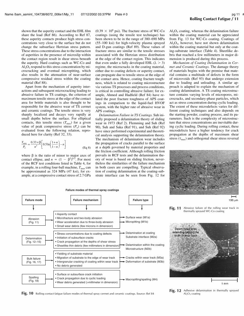
Rolling-Contact Fatigue Failure Modes inTS Cermet (WC-Co) and Ceramic (Al2O3)Coatings. Investigations relating to the RCFfailure modes of TS coatings are reported in Ref7, 74, 79, 84, and 85. These investigations haveclassified the fatigue failure modes on the basisof surface and subsurface observations in pre-and post-RCF conditions. Rolling-contact fa-tigue failure of TS coatings are generally cate-gorized in four main modes and named asabrasion, delamination, bulk failure, and spalling(M1–M4), as indicated in Fig. 10. A summaryof the underpinning failure mechanisms leadingto these failure modes is given subsequently, de-tails of which can be seen in the aforementionedreferences.
Abrasive Failure of Coated Rolling Elements.The combined effect of micropitting and surfacewear on the wear track of components in rollingcontact is collectively termed as abrasive failurein TS coatings. This failure mode is seen withboth ceramic (Al2O3) and cermet (WC-Co) coat-ings and with all TS coating techniques. A typ-ical example of this failure is shown in Fig. 11.Noncontacting three-dimensional interferometryof failed wear track indicates that the micropitsleading to abrasive failure are, on average, 50lm wide and a maximum of 5 lm deep. Abra-sive failure mode in TS coatings is thus not sig-nificantly different to those associated with roll-ing contact wear rolling contact wear (RCW) inconventional steel bearings; for example, Blau(Ref 13) has considered RCW as nucleation sitesfor initiating RCF. Similar failure was character-ized as “peeling” during a study of fatigue failuremodes of conventional steel ball bearings (Ref16), whereas in Ref 5, this type of failure wascharacterized as surface distress. In spite of thevarious terminologies used to distinguish similarfailure in steel bearings, the underpinning failuremechanism is associated with asperity contact inthe presence of microslip within the contact re-gion. Gross sliding, though not necessary for thistype of failure, is thought to promote micropit-ting.
Mechanism of Coating Abrasion in Rolling/Sliding Contacts. In the case of TS coatings, asimilar mechanism of asperity contact in thepresence of microslip and sliding is responsiblefor the micropitting and surface wear. Duringpartial elastohydrodynamic lubrication (EHL)conditions, that is, when lubrication regime is inthe mixed region (1 � k � 3, where k is non-dimensional film thickness), surface asperitiescome into contact. Under these conditions, it was
Name /bam_asmint_104738/6072_006e1/Mp_11 07/12/2002 03:37PM Plate # 0 pg 11 #
Rolling Contact Fatigue / 11
shown that the asperity contact and the EHL filmshare the load (Ref 86). According to Ref 87,these asperity contacts produce high stress con-centrations very close to the surface but do notchange the subsurface Hertzian stress pattern.These stress concentrations due to the interactionof asperities in the presence of microslip withinthe contact region result in shear stress beneaththe asperity. Hard coatings such as WC-Co andAl2O3 respond to this stress concentration by mi-crocracking and eventual micropitting, whichalso results in the attenuation of near-surfacecompressive residual stress within the coatingmaterial (Ref 88).
Apart from the mechanism of asperity inter-actions and subsequent microcracking leading toabrasive failure in TS coatings, the criterion ofmaximum tensile stress at the edge of the contactarea for brittle materials is also thought to beresponsible for the abrasive wear of TS cermetand ceramic coatings. The tensile stress is verysharply localized and decays very rapidly atsmall depths below the surface. For ellipticalcontacts, this tensile stress (Tmax) for a givenvalue of peak compressive stress (Po) can beevaluated from the following relation, repro-duced here for clarity (Ref 32, 33).
T
P n
n
nnmax .
. lno
= × +−
−0 330 5
113
β
(Eq 8)
where b is the ratio of minor to major axes ofcontact ellipse, and n � (1 � b2)0.5. For mostof the RCF test conditions listed in Table 4, forexample, in a rolling four-ball machine, Tmax canbe approximated as 324 MPa (47 ksi), for ex-ample, at a compressive contact stress of 2.7 GPa
Failure modes of thermal spray coatings
Failure mode Failure mechanism Failure type
• Asperity contact• Microfracture and two-body abrasion• Wear acceleration due to three-body abrasion• Small wear debris (few microns in dimension)
• Stress concentrations due to coating defects• Initiation of subsurface cracks• Crack propagation at the depths of shear stress• Sheetlike thin debris (few millimeters in dimension)
• Yielding of substrate material• Migration of substrate to the edge of wear track• Intergranular cracking of coating within wear track• No debris generated
• Surface or subsurface crack initiation• Crack propagation due to cyclic loading• Wear debris generated (>millimeter in dimension)
Surface wear (M1a)
Micropitting (M1b)
Delamination at coatingSubstrate interface (M2a)
Delamination within the coatingMicrostructure (M2b)
Cracks within wear track (M3a)Deformation of substrate (M3b)
Macropitting/spalling (M4)
Abrasion(Fig. 11)
Delamination(Fig. 12–15)
Bulk failure(Fig. 16, 17)
Spalling(Fig. 18)
Fig. 10 Rolling-contact fatigue failure modes of thermal spray cermet and ceramic coatings. Source: Ref 84
Fig. 11 Abrasive failure of the rolling wear track inthermally sprayed WC-Co coating
Fig. 12 Adhesive delamination in thermally sprayedAl2O3 coating
(0.39 � 106 psi). The fracture stress of WC-Cocoatings (using the tensile test technique) hasbeen shown to be in the range of 380–690 MPa(55–100 ksi) for high-velocity plasma sprayedand D-gun coatings (Ref 89). These values offracture stress are similar to the tensile stressesassociated with the Hertzian stress distributionat the edge of the contact region. This indicatesthat even under a fully developed EHL (k � 3)regime, the microcracks in the coating material,either due to coating defects or asperity contact,can propagate due to tensile stress at the edge ofthe contact area. Hence, coating fracture tough-ness, which is related to coating microstructurevia various TS processes and process conditions,is critical in controlling abrasive failure; for ex-ample, Ahmed and Hadfield (Ref 84) have re-lated the poor fracture toughness of APS coat-ings in comparison to the liquid-fuel HVOFsystem, with the higher rate of abrasive wear inAPS coatings.
Delamination Failure in TS Coatings. Suh ini-tially proposed a delamination theory of slidingwear in 1973 (Ref 2). Flemming and Suh (Ref90), Suh and Saka (Ref 91), and Suh (Ref 92)have since performed experimental and theoreti-cal analysis supporting the delamination theory.The mechanism of delamination wear includesthe propagation of cracks parallel to the surfaceat a depth governed by material properties andthe friction coefficient. Although rolling frictionprevails in RCF tests and the delamination the-ory of wear is based on sliding friction, never-theless the similarities of the failure mechanismin both cases are compelling. Typical observa-tion of coating delamination at the coating-sub-strate interface can be seen from Fig. 12 for
Al2O3 coating, whereas the delamination failurewithin the coating material can be appreciatedfrom Fig. 13 for WC-Co coating. Coatings ofAl2O3, however, have not shown delaminationwithin the coating material but only at the coat-ing-substrate interface (Table 4). Sheetlike de-bris that reached a few millimeters in major di-mension is produced during this process.
Mechanism of Coating Delamination in Cer-met and Ceramic Coatings. The damage theoryof materials begins with the premise that mate-rial contains a multitude of defects in the formof microvoids (Ref 93) that undergo extensiondue to loading and unloading. A similar ap-proach is adapted to explain the mechanism ofcoating delamination. A TS coating microstruc-ture contains varying levels of micropores, mi-crocracks, and secondary-phase particles, whichact as stress concentration during cyclic loading.The extent of these microdefects varies for dif-ferent coating techniques and also depends onthe starting powder, coating process, and its pa-rameters. Such is the complexity of microstruc-ture that stress concentrations are inevitable dur-ing cyclic loading. During rolling contact, thesemicrodefects have a higher tendency for crackpropagation at the depths of maximum shearstress (smax) and orthogonal shear stress reversal

Name /bam_asmint_104738/6072_006e1/Mp_12 07/12/2002 03:37PM Plate # 0 pg 12 #
12 / Wear Failures
Fig. 14 Subsurface crack observations during delami-nation failure of thermal spray coatings. (a)
Subsurface cracks in WC-Co-coated rolling cone at thedepths of maximum and orthogonal shear stress. (b) Prop-agated subsurface cracks leading to coating delaminationduring RCF failure of WC-Co coating
Fig. 13 Cohesive delamination in thermally sprayedWC-Co coating (backscattered electron image)
I
II
III
IV
I
II
III
IV
a Po
Driven rollingelement
WC-Co coating thickness >depth of max shear stress
Al2O3 or WC-Co coating thickness ≤depth of max shear stress
Driven rollingelement
Orthogonal shear stress = τorth = 0.21 × Po
Maximum shear stress = τmax = 0.35 × Po
Substrate
Coating
a = contact width; Po = peak compressive stress
Microstructural cracks (initiation)
Interfacial cracks (initiation)
Crack propagation
Joining of cracks
Delamination (adhesive or cohesive)
Depth of orthogonal shear stress = 0.35 × a
Depth of maximum shear stress = 0.5 × a
Fig. 15 Schematic of coating delamination process for cermet and ceramic coatings
(sorth) (Fig. 8). The location of these stresses inthe vicinity of the coating-substrate interface canthus significantly influence crack propagationdue to the mismatch of coating and substrateproperties and a high level of quenching stressat this interface (Ref 94). Circumferencial crackssimilar to those shown in Fig. 14 appear beneaththe surface at the depths of maximum shear andorthogonal shear stress for WC-Co coatings,whereas in the case of Al2O3 coatings, cracksgenerally appear at the coating-substrate inter-face. Hence, cohesive and adhesive delaminationis observed in cermets whereas adhesive delam-
ination is the preferred failure mode in ceramiccoatings.
Figure 15 gives a schematic of crack propa-gation behavior in ceramic and cermet coatings.The process can be summarized as follows:
● Crack initiation: For cermet (WC-Co) coat-ings, cracks initiate subsurface at differentdepths under the contact region but propagateat the depths of maximum shear stress andorthogonal shear stress (Fig. 14a). Thesecracks initiate due to stress concentrations inthe presence of microstructural defects. ForWC-Co coatings thinner than the depth ofmaximum shear stress, an additional factor ofstress concentrations is the mismatch of coat-ing-substrate properties at the interface. ForWC-Co coatings thicker than the depth ofmaximum shear stress, these cracks initiatewithin the coating microstructure; for coat-ings thinner than the depth of maximum shearstress, these cracks initiate within the coatingmicrostructure as well as at the coating-sub-
strate interface. For ceramic (Al2O3) coatings,cracks generally initiate at the coating-sub-strate interface.
● Crack propagation: For WC-Co coatingsthicker than the depth of maximum shearstress, initiated cracks propagate slowly in re-sponse to cyclic loading at their respectivedepths within the coating microstructure (Fig.14b). For WC-Co or ceramic (Al2O3) coat-ings thinner than the depth of maximum shearstress, the cracks at the coating-substrate in-terface propagate much faster than the cracksat the depth of orthogonal shear stress (i.e.,cracks within the coating microstructure) andresult in poor RCF performance of thinnercoatings.
● Crack extension: For WC-Co coatings thickerthan the depth of maximum shear stress, thecracks at maximum shear stress extend togreater lengths and ultimately join the cracksat the depth of orthogonal shear stress (Fig.14b). For coatings thinner than the depth ofmaximum shear stress or for ceramic (Al2O3)

Name /bam_asmint_104738/6072_006e1/Mp_13 07/12/2002 03:37PM Plate # 0 pg 13 #
Rolling Contact Fatigue / 13
Fig. 16 Bulk deformation failure of WC-Co coating, in-dicating cracks in the middle of the wear track
and substrate migration at the edge of the wear track
Po
Rolling direction
Width ofwear track
Coating
Coating
Crack in middle ofwear track—step III
Yielding of substrate—step I
Migration of substrate—step IV
Tensile stress within coating—step II
Substrate
Substrate
Fig. 17 Mechanism of bulk deformation Fig. 18 Spalling of thermally sprayed WC-Co coating
coatings, the cracks at interface had thegreater tendency of reaching the surface in-dependently, and, in some cases, they com-bine with the cracks at the depth of orthogo-nal shear stress and eventually reach thesurface.
● Delamination: For WC-Co coatings thickerthan the depth of maximum shear stress, thecracks from the depth of orthogonal shearstress reach the surface much more quicklythan the cracks at the depth of orthogonalshear stress, thereby leading to coating de-lamination at the depth of orthogonal shearstress. Contrary to this, for thinner WC-Co orceramic (Al2O3) coatings, interfacial delami-nation takes place.
Coating Failure Due to Bulk Deformation.Bulk deformation of substrate material is of pri-mary importance for the cases of hard coatings(WC-Co and Al2O3) on a soft substrate. This isbecause the contact stress can be in the elasticrange of the coating material and in the plasticrange of the substrate. The primary effect of thisis the plastic flow of substrate, leading to con-
formity of the contact region and a hump at theedge of the wear track. Figure 16 shows a typicalexample of such a failure in which the substratecould no longer support the coating, leading tobending and cracking of coating material in theinitial stages of RCF failure. As cyclic loadingcontinues, the coating cracks in the middle of thewear track due to its inability to plastically de-form under the tensile stress caused by the plas-tic flow of substrate material. During this failure,the plastic flow of the substrate continues, andthe substrate is pushed up at the edges of thewear track as it conforms to the geometry of thecounterbody, leading to subsequent cracking atthe edge of the wear track. Further cyclic loadingleads to crack propagation in tension, and thesubstrate finally emerges at the edge of weartrack. Because the crack propagation is progres-sive due to cyclic loading, this failure mode iscategorized as a RCF failure mode. Once theconformity of contact is such that the stresses inthe substrate are no longer in the plastic region,the substrate migration terminates, and a steadystate is reached. Figure 17 shows a schematic ofthis failure mode and indicates that substratehardness should be carefully selected (based oncontact loading) to combat this failure. Themechanism of bulk deformation is thus stronglydependent on the ability of the substrate materialto support the coating in relation to the contactstress and is marginally affected by the changesin either coating material or process.
Coating Failure Due to Spalling. Spalling isthe most commonly seen RCF failure in steelrolling-element bearings. Spalling fatigue is,however, the most rare mode of fatigue failurein TS coatings. Spall in TS coatings resemblesin appearance the spalls in conventional bear-ings, as shown in Fig. 18. It differs from delam-ination failure (discussed previously) in thesense that spall is contained within the weartrack and is circular or elliptical in appearance,with its surface area (or width-to-depth ratio)much smaller than that of delaminated coating.A comparison of Fig. 1,12 and 18 can distinguish
the appearance between the two failures. As withconventional steel bearings, spalls in TS coatingscan initiate from micropits, furrows, grindingmarks, or dents on the surface of a wear track.Also, subsurface inclusions and defects areknown to lead to spalling of rolling elements.Examination of the wear track of a spalled spec-imen in TS coatings indicates that substantialmicropitting of the wear track occurs before fa-tigue spall is produced. This highlights the pos-sibility that the fatigue spall in TS coatings ini-tiates from the micropits, and subsequent crackpropagation takes place due to cyclic loading. Itis also possible that once initiated, spalling canbe assisted by hydraulic pressure crack propa-gation (Ref 4). However, the exact mechanismof fatigue spall, that is, surface or subsurface ini-tiation and propagation, in TS coatings is notcompletely understood at this stage.
Design Considerations for RCF Applica-tions of TS Coatings. The design of surfaceoverlay coatings for tribological applications in-volving Hertzian contact loading not only re-quires a thorough understanding of the tribolog-ical conditions, for example, contact stress,lubrication, and friction, but also the influenceof coating processes, material, thickness, and therole of substrate material properties. Tribologistsoften have little choice about the former but caninfluence the coating performance by appropri-ate selection of the latter. The following thus pro-vides some insight into the design considerationsof coating-substrate material properties, coatingthickness, and coating processes to combat RCFfailure in TS coatings.
Substrate Material. The mechanism of bulkand interfacial delamination failure mode (dis-cussed above) indicated that the four most im-portant design considerations while selecting thesubstrate material are:
● Ability to support the coating● Higher coefficient of thermal expansion than
the coating material, to induce a certain de-gree of compressive residual stress within thecoating material
● Ability to withstand preheat temperature priorto thermal spraying
● Ability to plastically deform during shotpeening prior to the coating process, to pro-

Name /bam_asmint_104738/6072_006e1/Mp_14 07/12/2002 03:37PM Plate # 0 pg 14 #
14 / Wear Failures
mote mechanical interlock at the coating-sub-strate interface
The ratio (d � Po/r, where d is normalizedpressure) of the Hertzian contact stress (Po) tothe substrate yield strength (r) is thus a usefulindicator in determining the ability of the sub-strate to support the coating. Figure 19 showsthis effect and indicates that normalized contactstress (Po/r) can be used to benchmark candidatesubstrate materials.
Coating Thickness. Investigations of the de-lamination failure mode (both cohesive and ad-hesive) indicated that while selecting the coatingthickness for a given coating-substrate system, itis critical to shift the maximum and orthogonalshear stresses away from the coating substrateinterface. Using this technique can also simplifythe coating design by not having to functionallygrade the material to avoid the sharp stress gra-dient at the interface during the Hertzian loading.Hence, the ratio (D � n/W, where D is the nor-malized coating thickness, n is the average coat-ing thickness, and W is the depth of maximumshear stress) of the coating thickness to the depthof shear stress (W � 0.65b, where b is the lengthof the minor axis of the contact ellipse) is foundto be a good indicator of the coating substratesystem to combat adhesive delamination. Figure20 shows this effect and indicates that D valuecan have a significant influence on the fatigueperformance of coatings.
Coating Material. Investigation of failuremodes in TS coatings indicated that the selection
0 0.5 1 1.5 2 2.5 3
80
7060
5040
3020
100
Num
ber
of s
tres
s cy
cles
(◊1
06)
Normalized coating thickness (∆ = ξ/Ψ)
Normalized pressure(δ) = 1.7
Normalized pressure(δ) = 1.5
Suspended testsNo failure
Fig. 20 Influence of normalized coating thickness onthe performance of HVOF coating on 440C
steel substrate (r � 1840 MPa, or 267 ksi)
8
7
6
5
4
Log
(str
ess
cycl
es)
1 1.5 2 2.5 3Normalized pressure (δ = Po/σ)
Mild steelsubstrate
M50 or 440Csteel substrate
9Suspended testsNo failure
Fig. 19 Influence of normalized pressure on stress cy-cles (D � 1.5, Po � 2.7 GPa, or 0.39 � 106
psi)
of a hard, wear-resistant coating material re-quires a consideration of its coefficient of ther-mal expansion and the ability of the coating pro-cess to produce a dense coating microstructure.Within the boundaries of materials considered inpublished research (WC-Co and Al2O3), test re-sults indicate that the cermet coatings perfor-mance was superior to that of the ceramic coat-ings. This was mainly because of the followingthree reasons:
● The lower melting point of cermet materialthe allowed the melting of lamellas during theHVOF processes, whereas ceramic was par-tially melted, resulting in a lower cohesiveand adhesive strength.
● Although higher temperatures during the APSprocess melted the ceramic particles, the ve-locities achieved are generally much lowerthan the HVOF system, resulting in porousmicrostructure and thus lower strength.
● A higher lamella temperature during the APSprocess would have a high rate of cooling(quenching) on impact with the underlyingsurface, which can lead to internal cracking.
These factors contributed toward lower ad-hesive and cohesive strength of ceramic coatingsand indicate the need for an interfacial layer.With the advancements of high-velocity plasmasystems, however, it may be possible to improveRCF of TS ceramics in the future.
Coating Process(es). The most important con-sideration while selecting the coating process forRCF applications is its ability to produce a densecoating microstructure, resulting in a higher me-chanical strength. There are a number of waysto analyze this, for example, porosity measure-ments, x-ray diffraction pattern, microhardnessand bond strength. Experimental research has in-dicated that a useful measure for RCF applica-tions is to compare the indentation fracturetoughness (KIc) of the coating material. Sofar, HVOF-deposited WC-Co coatings with KIc
� 1.7 MPa m have shown a fatigue lifein excess of 70 million stress cycles for coatingdesign parameters of D � 1.5 and d � 1.5 (e.g.,Ref 84).
REFERENCES
1. N.P. Suh, An overview of the DelaminationTheory of Wear, Wear, Vol 44, 1977, p 1–16
2. N.P. Suh, The Delamination Theory ofWear, Wear, Vol 25, 1973, p 111–124
3. D. Tabor, The Mechanism of Rolling Fric-tion, Part II: The Elastic Range, Proc. R.Soc. A, Vol 229, 1955, p 198–220
4. S. Way, Pitting Due to Rolling Contact, J.Appl. Mech., 1935, p A49–A58
5. T.E. Tallian, On Competing Failure Modesin Rolling Contact, ASLE Trans., Vol 10,1967, p 418–439
6. M. Hadfield, T.A. Stolarski, and R.T. Cun-dill, Failure Modes of Ceramics in RollingContact, Proc. R. Soc. A, Vol 443, 1993, p607–621
7. R. Ahmed and M. Hadfield, Failure Modesof Plasma Sprayed WC-Co Coated RollingElements, Wear, Vol 230, 1999, p 39–55
8. J.V. Poplawski, S.M. Peters, and E.V. Zar-etsky, Effect of Roller Profile on CylindricalRoller Bearing Life, Part I: Comparison ofBearing Life Theories, Tribol. Trans., Vol 44(No. 3), 2001, p 339–350
9. T.E. Tallian, Data Fitted Bearing Life Pre-diction Model for Variable Operating Con-ditions, Tribol. Trans., Vol 42 (No. 1), 1999,p 241–249
10. Y. Li, T.R. Kurfess, and S.Y. Liang, Sto-chastic Prognostics for Rolling ElementBearings, Mech. Syst. Signal Process., Vol14 (No. 5), 2000, p 747–762
11. R.S. Hyde, Contact Fatigue of HardenedSteels, Fatigue and Fracture, Vol 19, ASMHandbook, 1996, p 680–690
12. W.A. Glaeser and S.J. Shaffer, Contact Fa-tigue, Fatigue and Fracture, Vol 19, ASMHandbook, 1996, p 331–336
13. P.J. Blau, Rolling Contact Wear, Friction,Lubrication, and Wear Technology, Vol 18,ASM Handbook, 1992, p 257–262
14. W.D. Syniuta and C.J. Corrow, A ScanningElectron Microscope Fractographic Study ofRolling Contact Fatigue, Wear, Vol 15,1970, p 187–199
15. J.A. Martin and A.D. Eberhardt, Identifica-tion of Potential Failure Nuclei in RollingContact Fatigue, J. Basic Eng. (Trans.ASME), 1967, p 932–942
16. W.E. Littmann and R.L. Widner, Propaga-tion of Contact Fatigue from Surface andSubsurface Origins, J. Basic Eng. (Trans.ASME), 1966, p 624–636
17. W.E. Littmann, The Mechanism of ContactFatigue, Conf. Proc. An InterdisciplinaryApproach to the Lubrication of Concen-trated Contacts, National Aeronautics andSpace Administration, 1969, p 309–377
18. E.V. Zaretsky, “Life Factors for RollingBearings,” Society of Tribology and Lubri-cation Engineers (STLE) publication, 1999
19. R.A. Guyer, Rolling Bearings Handbookand Trouble Shooting Guide, CRC Press,1996
20. T. Harris, Rolling Bearing Analysis, 3rd ed.,John Wiley & Sons, 1991
21. Anon, Friction, Wear, and LubricationTerms and Definitions, 1st revision, Orga-nization for Economic Co-Operation andDevelopment, Paris, 1968
22. F.J. Wren and C.A. Moyer, Modes of Fa-tigue Failures in Rolling Element Bearings,Proc. Inst. Mech. Eng., Vol 179 (Part 3D),1964-1965, p 236–247
23. Y.P. Chiu, T.E. Tallian, and J.I. McCool, AnEngineering Model of Spalling Fatigue inRolling Contact—The Subsurface Model,Wear, Vol 17, 1971, p 433–446
24. T.E. Tallian and J.I. McCool, An Engineer-ing Model of Spalling Fatigue in RollingContact—The Surface Model and Engineer-ing Discussion and Illustrative Examples,Wear, Vol 17, 1971, p 447–480
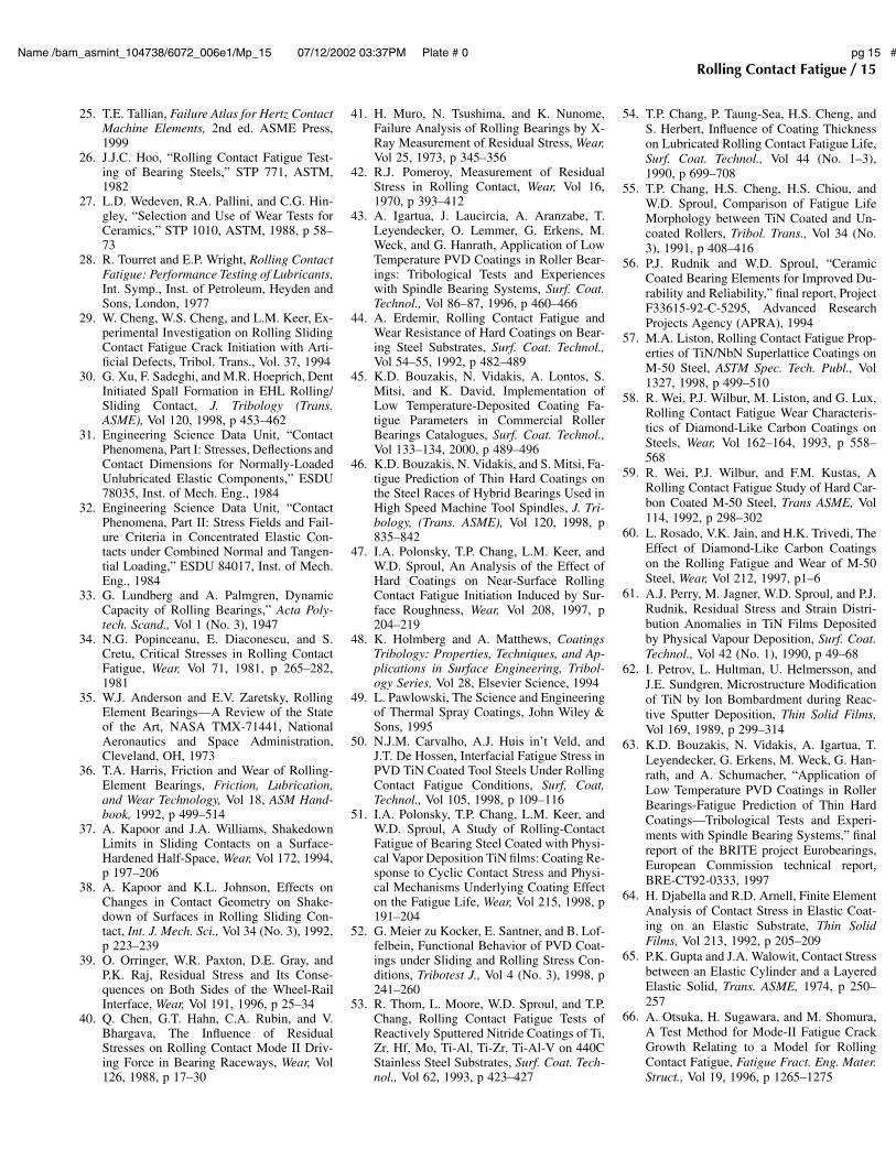
Name /bam_asmint_104738/6072_006e1/Mp_15 07/12/2002 03:37PM Plate # 0 pg 15 #
Rolling Contact Fatigue / 15
25. T.E. Tallian, Failure Atlas for Hertz ContactMachine Elements, 2nd ed. ASME Press,1999
26. J.J.C. Hoo, “Rolling Contact Fatigue Test-ing of Bearing Steels,” STP 771, ASTM,1982
27. L.D. Wedeven, R.A. Pallini, and C.G. Hin-gley, “Selection and Use of Wear Tests forCeramics,” STP 1010, ASTM, 1988, p 58–73
28. R. Tourret and E.P. Wright, Rolling ContactFatigue: Performance Testing of Lubricants,Int. Symp., Inst. of Petroleum, Heyden andSons, London, 1977
29. W. Cheng, W.S. Cheng, and L.M. Keer, Ex-perimental Investigation on Rolling SlidingContact Fatigue Crack Initiation with Arti-ficial Defects, Tribol. Trans., Vol. 37, 1994
30. G. Xu, F. Sadeghi, and M.R. Hoeprich, DentInitiated Spall Formation in EHL Rolling/Sliding Contact, J. Tribology (Trans.ASME), Vol 120, 1998, p 453–462
31. Engineering Science Data Unit, “ContactPhenomena, Part I: Stresses, Deflections andContact Dimensions for Normally-LoadedUnlubricated Elastic Components,” ESDU78035, Inst. of Mech. Eng., 1984
32. Engineering Science Data Unit, “ContactPhenomena, Part II: Stress Fields and Fail-ure Criteria in Concentrated Elastic Con-tacts under Combined Normal and Tangen-tial Loading,” ESDU 84017, Inst. of Mech.Eng., 1984
33. G. Lundberg and A. Palmgren, DynamicCapacity of Rolling Bearings,” Acta Poly-tech. Scand., Vol 1 (No. 3), 1947
34. N.G. Popinceanu, E. Diaconescu, and S.Cretu, Critical Stresses in Rolling ContactFatigue, Wear, Vol 71, 1981, p 265–282,1981
35. W.J. Anderson and E.V. Zaretsky, RollingElement Bearings—A Review of the Stateof the Art, NASA TMX-71441, NationalAeronautics and Space Administration,Cleveland, OH, 1973
36. T.A. Harris, Friction and Wear of Rolling-Element Bearings, Friction, Lubrication,and Wear Technology, Vol 18, ASM Hand-book, 1992, p 499–514
37. A. Kapoor and J.A. Williams, ShakedownLimits in Sliding Contacts on a Surface-Hardened Half-Space, Wear, Vol 172, 1994,p 197–206
38. A. Kapoor and K.L. Johnson, Effects onChanges in Contact Geometry on Shake-down of Surfaces in Rolling Sliding Con-tact, Int. J. Mech. Sci., Vol 34 (No. 3), 1992,p 223–239
39. O. Orringer, W.R. Paxton, D.E. Gray, andP.K. Raj, Residual Stress and Its Conse-quences on Both Sides of the Wheel-RailInterface, Wear, Vol 191, 1996, p 25–34
40. Q. Chen, G.T. Hahn, C.A. Rubin, and V.Bhargava, The Influence of ResidualStresses on Rolling Contact Mode II Driv-ing Force in Bearing Raceways, Wear, Vol126, 1988, p 17–30
41. H. Muro, N. Tsushima, and K. Nunome,Failure Analysis of Rolling Bearings by X-Ray Measurement of Residual Stress, Wear,Vol 25, 1973, p 345–356
42. R.J. Pomeroy, Measurement of ResidualStress in Rolling Contact, Wear, Vol 16,1970, p 393–412
43. A. Igartua, J. Laucircia, A. Aranzabe, T.Leyendecker, O. Lemmer, G. Erkens, M.Weck, and G. Hanrath, Application of LowTemperature PVD Coatings in Roller Bear-ings: Tribological Tests and Experienceswith Spindle Bearing Systems, Surf. Coat.Technol., Vol 86–87, 1996, p 460–466
44. A. Erdemir, Rolling Contact Fatigue andWear Resistance of Hard Coatings on Bear-ing Steel Substrates, Surf. Coat. Technol.,Vol 54–55, 1992, p 482–489
45. K.D. Bouzakis, N. Vidakis, A. Lontos, S.Mitsi, and K. David, Implementation ofLow Temperature-Deposited Coating Fa-tigue Parameters in Commercial RollerBearings Catalogues, Surf. Coat. Technol.,Vol 133–134, 2000, p 489–496
46. K.D. Bouzakis, N. Vidakis, and S. Mitsi, Fa-tigue Prediction of Thin Hard Coatings onthe Steel Races of Hybrid Bearings Used inHigh Speed Machine Tool Spindles, J. Tri-bology, (Trans. ASME), Vol 120, 1998, p835–842
47. I.A. Polonsky, T.P. Chang, L.M. Keer, andW.D. Sproul, An Analysis of the Effect ofHard Coatings on Near-Surface RollingContact Fatigue Initiation Induced by Sur-face Roughness, Wear, Vol 208, 1997, p204–219
48. K. Holmberg and A. Matthews, CoatingsTribology: Properties, Techniques, and Ap-plications in Surface Engineering, Tribol-ogy Series, Vol 28, Elsevier Science, 1994
49. L. Pawlowski, The Science and Engineeringof Thermal Spray Coatings, John Wiley &Sons, 1995
50. N.J.M. Carvalho, A.J. Huis in’t Veld, andJ.T. De Hossen, Interfacial Fatigue Stress inPVD TiN Coated Tool Steels Under RollingContact Fatigue Conditions, Surf, Coat,Technol., Vol 105, 1998, p 109–116
51. I.A. Polonsky, T.P. Chang, L.M. Keer, andW.D. Sproul, A Study of Rolling-ContactFatigue of Bearing Steel Coated with Physi-cal Vapor Deposition TiN films: Coating Re-sponse to Cyclic Contact Stress and Physi-cal Mechanisms Underlying Coating Effecton the Fatigue Life, Wear, Vol 215, 1998, p191–204
52. G. Meier zu Kocker, E. Santner, and B. Lof-felbein, Functional Behavior of PVD Coat-ings under Sliding and Rolling Stress Con-ditions, Tribotest J., Vol 4 (No. 3), 1998, p241–260
53. R. Thom, L. Moore, W.D. Sproul, and T.P.Chang, Rolling Contact Fatigue Tests ofReactively Sputtered Nitride Coatings of Ti,Zr, Hf, Mo, Ti-Al, Ti-Zr, Ti-Al-V on 440CStainless Steel Substrates, Surf. Coat. Tech-nol., Vol 62, 1993, p 423–427
54. T.P. Chang, P. Taung-Sea, H.S. Cheng, andS. Herbert, Influence of Coating Thicknesson Lubricated Rolling Contact Fatigue Life,Surf. Coat. Technol., Vol 44 (No. 1–3),1990, p 699–708
55. T.P. Chang, H.S. Cheng, H.S. Chiou, andW.D. Sproul, Comparison of Fatigue LifeMorphology between TiN Coated and Un-coated Rollers, Tribol. Trans., Vol 34 (No.3), 1991, p 408–416
56. P.J. Rudnik and W.D. Sproul, “CeramicCoated Bearing Elements for Improved Du-rability and Reliability,” final report, ProjectF33615-92-C-5295, Advanced ResearchProjects Agency (APRA), 1994
57. M.A. Liston, Rolling Contact Fatigue Prop-erties of TiN/NbN Superlattice Coatings onM-50 Steel, ASTM Spec. Tech. Publ., Vol1327, 1998, p 499–510
58. R. Wei, P.J. Wilbur, M. Liston, and G. Lux,Rolling Contact Fatigue Wear Characteris-tics of Diamond-Like Carbon Coatings onSteels, Wear, Vol 162–164, 1993, p 558–568
59. R. Wei, P.J. Wilbur, and F.M. Kustas, ARolling Contact Fatigue Study of Hard Car-bon Coated M-50 Steel, Trans ASME, Vol114, 1992, p 298–302
60. L. Rosado, V.K. Jain, and H.K. Trivedi, TheEffect of Diamond-Like Carbon Coatingson the Rolling Fatigue and Wear of M-50Steel, Wear, Vol 212, 1997, p1–6
61. A.J. Perry, M. Jagner, W.D. Sproul, and P.J.Rudnik, Residual Stress and Strain Distri-bution Anomalies in TiN Films Depositedby Physical Vapour Deposition, Surf. Coat.Technol., Vol 42 (No. 1), 1990, p 49–68
62. I. Petrov, L. Hultman, U. Helmersson, andJ.E. Sundgren, Microstructure Modificationof TiN by Ion Bombardment during Reac-tive Sputter Deposition, Thin Solid Films,Vol 169, 1989, p 299–314
63. K.D. Bouzakis, N. Vidakis, A. Igartua, T.Leyendecker, G. Erkens, M. Weck, G. Han-rath, and A. Schumacher, “Application ofLow Temperature PVD Coatings in RollerBearings-Fatigue Prediction of Thin HardCoatings—Tribological Tests and Experi-ments with Spindle Bearing Systems,” finalreport of the BRITE project Eurobearings,European Commission technical report,BRE-CT92-0333, 1997
64. H. Djabella and R.D. Arnell, Finite ElementAnalysis of Contact Stress in Elastic Coat-ing on an Elastic Substrate, Thin SolidFilms, Vol 213, 1992, p 205–209
65. P.K. Gupta and J.A. Walowit, Contact Stressbetween an Elastic Cylinder and a LayeredElastic Solid, Trans. ASME, 1974, p 250–257
66. A. Otsuka, H. Sugawara, and M. Shomura,A Test Method for Mode-II Fatigue CrackGrowth Relating to a Model for RollingContact Fatigue, Fatigue Fract. Eng. Mater.Struct., Vol 19, 1996, p 1265–1275
Name /bam_asmint_104738/6072_006e1/Mp_16 07/12/2002 03:37PM Plate # 0 pg 16 #
16 / Wear Failures
67. M. Hadfield and T.A. Stolarski, The Effectof the Test Machine on the Failure Mode inLubricated Rolling Contact of Silicon Ni-tride, Tribol. Int., Vol 28, 1995, p 377–382
68. J. He, C. Bai, K. Xu, and N. Hu, Improvingthe Anticorrosion and Mechanical Behav-iour of PACVD TiN, Surf. Coat. Technol.,Vol 74–75, 1995, p 387–393
69. J. He, K. Xu, and N. Hu, Evaluation ofBonding Strength of Thin Hard Films bySpherical Rolling Test, Surf. Coat. Technol.,Vol 97, 1997, p 295–298
70. K. Xu, N. Hu, and J. He, Evaluation of theBond Strength of Hard Coatings by the Con-tact Fatigue Test, J. Adhes. Sci. Technol., Vol12, 1998, p 1055–1069
71. J.F. Dill, M.N. Gardos, H.E. Hintermann,and H.J. Boving, Rolling Contact FatigueEvaluation of Hardcoated Bearing Steels,ASCE Publ., 1984, p 230–240
72. L. Chao, R. Lakshminarayanan, D.K.Shetty, and R. Cutler, Rolling Contact Fa-tigue and Wear of CVD SiC with ResidualSurface Compression, J. Am. Ceram. Soc.,Vol 78 (No. 9) 1995, p 2307–2313
73. A. Savan, H.J. Boving, F. Fluehmann, andH.E. Hintermann, Increased Performance ofBearings Using TiC-Coated Balls, J. Phys.(France) IV, Colloque C7, Supplement au J.Phys. (France) III, Vol 3, Nov 1993, p 943–947
74. R. Nieminen, P. Vouristo, K. Niemi, T. Man-tyla, and G. Barbezat, Rolling Contact Fa-tigue Failure Mechanisms in Plasma andHVOF Sprayed WC-Co Coatings, Wear, Vol212, 1997, p 66–77
75. M. Yoshida, K. Tani, A. Nakahira, A. Na-kajima, and T. Mawatari, Durability and Tri-bological Properties of Thermally Sprayed
WC Cermet Coatings in Rolling/SlidingContact, Proc. ITSC, May 1995 (Kobe), p663–668
76. R. Ahmed and M. Hadfield, Rolling ContactFatigue Performance of Detonation GunCoated Elements, Tribol. Int., Vol 30, 1997,p 129–137
77. R.Ahmed, M. Hadfield, Rolling Contact Fa-tigue Behaviour of Thermally Sprayed Roll-ing Elements, Surf. Coat. Technol., Vol 82,1996, p176–186
78. B.Y. Sarma and M.M. Mayuram, SomeStudies on Life Prediction of ThermalSprayed Coatings under Rolling ContactConditions, J. Tribology (Trans ASME), Vol122, 2000, p 503–510
79. A. Nakajima, T. Mawatari, M. Yoshida, K.Tani, and A. Nakahira, Effects of CoatingThickness and Slip Ratio on Durability ofThermally Sprayed WC Cermet Coatings inRolling/Sliding Contact, Wear, Vol 241,2000, p 166–173
80. A. Makela, P. Vouristo, M. Lahdensuo, K.Niemi, and T. Mantyla, Rolling Contact Fa-tigue Testing of Thermally Sprayed Coat-ings, Proc. Seventh Int. Thermal SprayConf., 20–24 June 1994 (Boston, MA),ASM International, 1994, p 759–763
81. R. Ahmed and M. Hadfield, Wear of High-Velocity Oxy-Fuel (HVOF)-Coated Conesin Rolling Contact, Wear, Vol 203–204,1997, p 98–106
82. R. Ahmed, M. Hadfield, Influence of Coat-ing Thickness and Contact Stress on the Fa-tigue Failure of HVOF Coatings, Int. Ther-mal Spray Conf., (Singapore), ASMInternational, 2001, p 1009–1015
83. S. Tobe, S. Kodama, and H. Misawa, Roll-ing Fatigue Behaviour of Plasma Sprayed
Coatings on Aluminum Alloy, Proc. Nat.Thermal Spray Conf. 1990 (Tokyo, Japan),ASM International, 1990, p 171–178
84. R. Ahmed and M. Hadfield, Mechanisms ofFatigue Failure in Thermal Spray Coatings,J. Therm. Spray Technol., in press 2002
85. R. Ahmed, Contact Fatigue Failure Modesof HVOF Coatings, Wear, submitted forpublication 2001
86. K.L. Johnson, J.A. Greenwood, and S.Y.Poon, A Simple Theory of Asperity Contactin Elastohydrodynamic Lubrication, Wear,Vol 19, 1972, p 91–108
87. D. Berthe, L. Flamand, and M. Godet, Mi-cropitting in Hertzian Contacts, J. Lubr.Technol., (Trans. ASME), Vol 102, 1980, p479–485
88. R. Ahmed and M. Hadfield, ExperimentalMeasurement of Residual Stress Fieldwithin Thermally Sprayed Rolling Ele-ments, Wear, Vol 209, 1997, p 84–95
89. R.C. Tucker, Jr., Structure Property Rela-tionship in Deposits Produced by PlasmaSpray and Detonation Gun Techniques, J.Vac. Sci. Technol., Vol 11, 1994, p 725–734
90. J.W. Flemming and N.P. Suh, Mechanics ofCrack Propagation in Delamination Wear,Wear, Vol 44, 1977, p 39–56
91. N.P. Suh and N. Saka, Fundamentals of Tri-bology, Int. Conf. Fundamentals of Tribol-ogy, Massachusetts Institute of TechnologyPress, 1980
92. N.P. Suh, Tribophysics, Prentice Hall, 198693. P.J. RabIer, Some Remarks on Damage The-
ory, Int. J. Eng. Sci., Vol 27, 1989, p 29–5494. S.C. Gill, “Residual Stress in Plasma
Sprayed Deposits,” Ph.D. dissertation, Gon-ville and Caius College, Cambridge, U.K.,1993