
Roller proile rail guides LLU - SKF. · PDF fileators and ball screws to profile rail guides...
64
Roller proile rail guides LLU
Transcript of Roller proile rail guides LLU - SKF. · PDF fileators and ball screws to profile rail guides...

Roller proile rail guidesLLU

2
skf.com | beyondzero.com
® SKF, BeyondZero, SKF Linear Guide Designer, SKF Linear Guide Simulator, SKF Linear Guides Calculator and SKF Linear Guides Select are registered trademarks of the SKF Group.
© SKF Group 2017The contents of this publication are the copyright of the publisher and may not be reproduced (even extracts) unless prior written permission is granted. Every care has been taken to ensure the accu-racy of the information contained in this publication but no liability can be accepted for any loss or damage whether direct, indirect or consequential arising out of the use of the information contained herein.
PUB MT/P1 16404/1 EN · May 2017
Certain image(s) used under license from Shutterstock.com.
3
ContentsSKF introduction . . . . . . . . . . . . . . . . . . . . . . . . . . . . . . 4
Advanced machine tool components and systems . . . . . . 6
A Foreword . . . . . . . . . . . . . . . . . . . . . . . . . . . . . . . . 8
Features and beneits . . . . . . . . . . . . . . . . . . . . . . . . . . . . . 9
Basic design . . . . . . . . . . . . . . . . . . . . . . . . . . . . . . . . . . . 10
Seals . . . . . . . . . . . . . . . . . . . . . . . . . . . . . . . . . . . . . . . . . 11
Load rating . . . . . . . . . . . . . . . . . . . . . . . . . . . . . . . . . . . . 11
Rigidity . . . . . . . . . . . . . . . . . . . . . . . . . . . . . . . . . . . . . . . . 12
Preload classes . . . . . . . . . . . . . . . . . . . . . . . . . . . . . . . . . 12
Accuracy . . . . . . . . . . . . . . . . . . . . . . . . . . . . . . . . . . . . . . 13
Permissible operating conditions . . . . . . . . . . . . . . . . . . . 14
Friction . . . . . . . . . . . . . . . . . . . . . . . . . . . . . . . . . . . . . . . 14
Lubrication . . . . . . . . . . . . . . . . . . . . . . . . . . . . . . . . . . . . 14
Calculation bases . . . . . . . . . . . . . . . . . . . . . . . . . . . . . . . 15
Factors of inluence . . . . . . . . . . . . . . . . . . . . . . . . . . . . . . 18
Modiied basic rating life . . . . . . . . . . . . . . . . . . . . . . . . . . 19
Legend . . . . . . . . . . . . . . . . . . . . . . . . . . . . . . . . . . . . . . . . 20
SKF calculation program . . . . . . . . . . . . . . . . . . . . . . . . . . 22
Product data overview . . . . . . . . . . . . . . . . . . . . . . . . . . . 23
B Product data . . . . . . . . . . . . . . . . . . . . . . . . . . . . .24
Carriages . . . . . . . . . . . . . . . . . . . . . . . . . . . . . . . . . . . . . . 24
Carriage LLUHC … A . . . . . . . . . . . . . . . . . . . . . . . . . . . 26
Carriage LLUHC … LA . . . . . . . . . . . . . . . . . . . . . . . . . 28
Carriage LLUHC … R . . . . . . . . . . . . . . . . . . . . . . . . . . 30
Carriage LLUHC … LR . . . . . . . . . . . . . . . . . . . . . . . . . 32
Rails . . . . . . . . . . . . . . . . . . . . . . . . . . . . . . . . . . . . . . . . . . 25
LLUHR rails . . . . . . . . . . . . . . . . . . . . . . . . . . . . . . . . . 34
LLUHR … D4 rails . . . . . . . . . . . . . . . . . . . . . . . . . . . . . 34
LLUHR … D6 rails . . . . . . . . . . . . . . . . . . . . . . . . . . . . . 34
LLUHR … D8 rails . . . . . . . . . . . . . . . . . . . . . . . . . . . . . 34
Joint rail tracks . . . . . . . . . . . . . . . . . . . . . . . . . . . . . . . 36
C Accessories . . . . . . . . . . . . . . . . . . . . . . . . . . . . . . . 37
Accessories overview . . . . . . . . . . . . . . . . . . . . . . . . . . . . 37
Scraper plate . . . . . . . . . . . . . . . . . . . . . . . . . . . . . . . . . . . 38
Additional front seal . . . . . . . . . . . . . . . . . . . . . . . . . . . . . 39
Seal kit . . . . . . . . . . . . . . . . . . . . . . . . . . . . . . . . . . . . . . . . 40
Lubrication adaptors . . . . . . . . . . . . . . . . . . . . . . . . . . . . . 41
D Mounting and maintenance . . . . . . . . . . . . . . . . . . .44
General instructions . . . . . . . . . . . . . . . . . . . . . . . . . . . . . 44
Typical mounting examples . . . . . . . . . . . . . . . . . . . . . . . 44
Lubrication . . . . . . . . . . . . . . . . . . . . . . . . . . . . . . . . . . . . 49
Grease lubrication . . . . . . . . . . . . . . . . . . . . . . . . . . . . . . . 50
Oil lubrication . . . . . . . . . . . . . . . . . . . . . . . . . . . . . . . . . . 52
E Ordering keys and speciication sheets . . . . . . . . . . . 54
Ordering key LLU system . . . . . . . . . . . . . . . . . . . . . . . . . 54
Ordering key LLU carriages. . . . . . . . . . . . . . . . . . . . . . . . 55
Ordering key LLU rails . . . . . . . . . . . . . . . . . . . . . . . . . . . . 56
Ordering key LLU accessories . . . . . . . . . . . . . . . . . . . . . . 57
Speciication sheets – Roller proile rail guide LLU . . . . . . 58

4
From one simple but
inspired solution to
a misalignment
problem in a textile
mill in Sweden, and
fifteen employees in
1907, SKF has
grown to become a
global industrial
knowledge leader.
Over the years, we have built on our exper-
tise in bearings, extending it to seals, mecha-
tronics, services and lubrication systems.
Our knowledge network includes 46 000
employees, 15 000 distributor partners,
offices in more than 130 countries, and a
growing number of SKF Solution Factory
sites around the world.
Research and development
We have hands-on experience in over forty
industries based on our employees’ know-
ledge of real life conditions. In addition, our
world-leading experts and university part-
ners pioneer advanced theoretical research
and development in areas including tribol-
ogy, condition monitoring, asset manage-
ment and bearing life theory. Our ongoing
commitment to research and devel opment
helps us keep our customers at the forefront
of their industries.
Meeting the toughest challenges
Our network of knowledge and experience,
along with our understanding of how our
core technologies can be combined, helps
us create innovative solutions that meet the
toughest of challenges. We work closely with
our customers throughout the asset life
cycle, helping them to profitably and
re spon sibly grow their businesses.
SKF Solution Factory makes SKF knowledge and manu facturing expertise available locally to provide unique solutions and services to our customers.
Working with SKF IT and logistics systems and application experts, SKF Authorized Distributors deliver a valuable mix of product and application knowledge to customers worldwide.
Working for a sustainable future
Since 2005, SKF has worked to reduce the
negative environmental impact from our
operations and those of our suppliers. Our
continuing technology development resulted
in the introduction of the SKF BeyondZero
portfolio of products and services which im-
prove efficiency and reduce energy losses,
as well as enable new technol ogies har-
nessing wind, solar and ocean power. This
combined approach helps reduce the en vir-
on mental impact both in our oper ations and
our customers’ oper ations.
SKF – the knowledge engineering company

5
BearingsSKF is the world leader in the design, development and manufacture of high performance rolling bearings, plain bearings, bearing units and housings.
Machinery maintenanceCondition monitoring technologies and main-tenance services from SKF can help minimize unplanned downtime, improve operational efficiency and reduce maintenance costs.
Sealing solutionsSKF offers standard seals and custom engineered sealing solutions to increase uptime, improve machine reliability, reduce friction and power losses, and extend lubricant life.
MechatronicsSKF fly-by-wire systems for aircraft and drive-by-wire systems for off-road, agricultural and forklift applications replace heavy, grease or oil consuming mechanical and hydraulic systems.
Lubrication solutionsFrom specialized lubricants to state-of-the-art lubrication systems and lubrication management ser vices, lubrication solutions from SKF can help to reduce lubrication related downtime and lubricant consumption.
Actuation and motion controlWith a wide assortment of products – from actu-ators and ball screws to profile rail guides – SKF can work with you to solve your most pressing linear system challenges.
Our knowledge – your successSKF Life Cycle Management is how we combine our technology
platforms and advanced ser vices, and apply them at each stage
of the asset life cycle, to help our customers to be more
success ful, sustainable and profitable.
Working closely with you
Our objective is to help our customers
improve productivity, minimize main ten-
ance, achieve higher energy and resource
efficiency, and optimize designs for long
service life and reliability.
Innovative solutions
Whether the application is linear or rotary
or a combination, SKF engineers can work
with you at each stage of the asset life cycle
to improve machine performance by looking
at the entire application. This approach
doesn’t just focus on individual components
like bearings or seals. It looks at the whole
application to see how each com po nent in-
teracts with each other.
Design optimization and verification
SKF can work with you to optimize current
or new designs with proprietary 3-D mod-
ell ing software that can also be used as a
virtual test rig to confirm the integrity of the
design.
SKF Life Cycle Management
Design and developManufacture and test
Spe
cific
ation
Install a
nd com
mis
sion
Operate and monitor
Maintain and repair
6
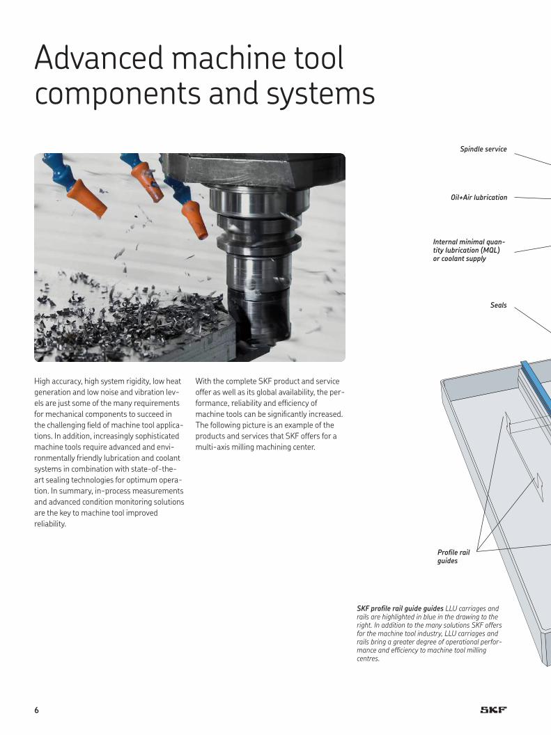
High accuracy, high system rigidity, low heat
generation and low noise and vibration lev-
els are just some of the many requirements
for mechanical components to succeed in
the challenging ield of machine tool applica-
tions. In addition, increasingly sophisticated
machine tools require advanced and envi-
ronmentally friendly lubrication and coolant
systems in combination with state-of-the-
art sealing technologies for optimum opera-
tion. In summary, in-process measurements
and advanced condition monitoring solutions
are the key to machine tool improved
reliability.
With the complete SKF product and service
offer as well as its global availability, the per-
formance, reliability and eficiency of
machine tools can be signiicantly increased.
The following picture is an example of the
products and services that SKF offers for a
multi-axis milling machining center.
Advanced machine tool components and systems
Proile rail guides
Seals
Spindle service
Internal minimal quan-tity lubrication (MQL) or coolant supply
Oil+Air lubrication
SKF proile rail guide guides LLU carriages and rails are highlighted in blue in the drawing to the right. In addition to the many solutions SKF offers for the machine tool industry, LLU carriages and rails bring a greater degree of operational perfor-mance and eficiency to machine tool milling centres.

7
Proile rail guides
Condition monitoring
Super-precision bearings
Ball screw support bearings
Seals
Axial-radial Cylindrical roller bearings
Ball and Roller screws
Precision lock nuts
Internal MQL unit for SKF LubriLean
External MQL unit for SKF LubriLean
Gear pump unit for SKF MonoFlex
Coolant pump for spindle
Coolant pump for tool and workpiece
External MQL or coolant supply
Precision lock nutsGear pump unit for SKF Oil+Air
8
Foreword
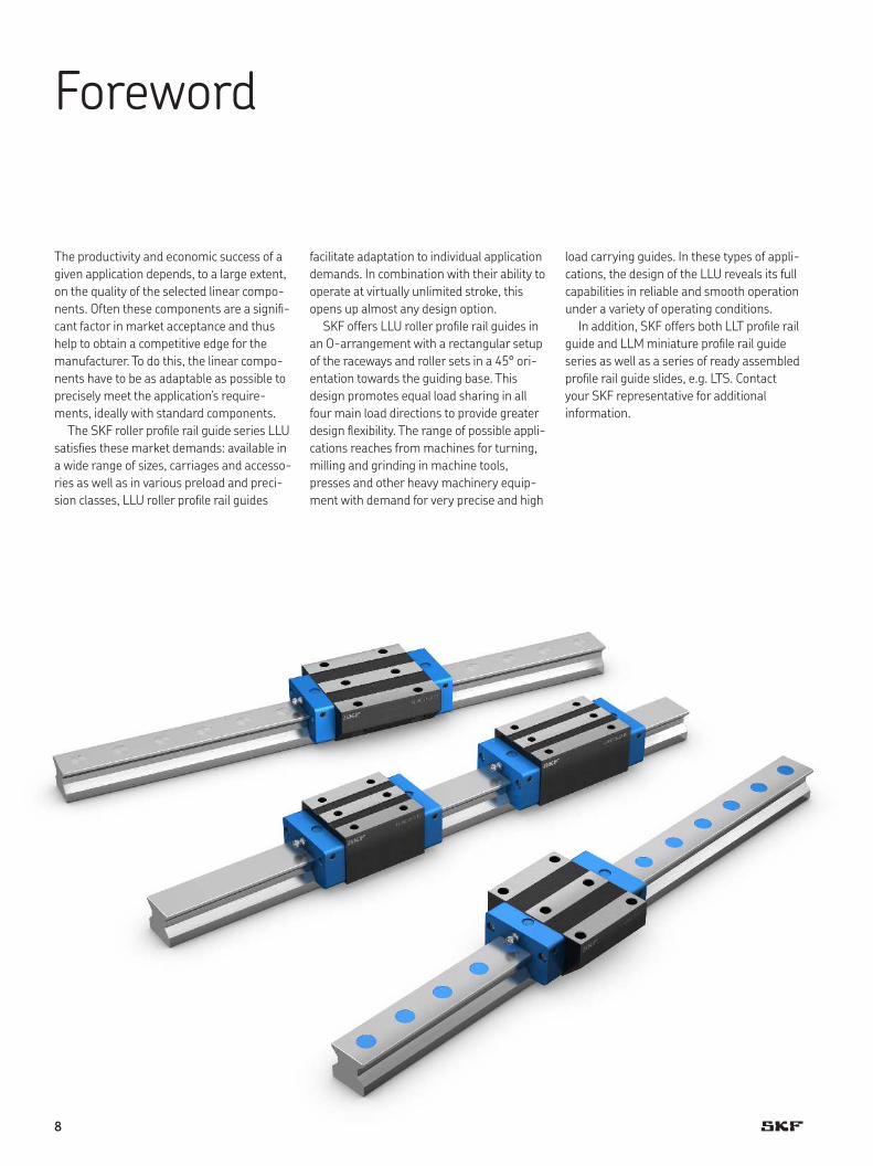
The productivity and economic success of a
given application depends, to a large extent,
on the quality of the selected linear compo-
nents. Often these components are a signii-
cant factor in market acceptance and thus
help to obtain a competitive edge for the
manufacturer. To do this, the linear compo-
nents have to be as adaptable as possible to
precisely meet the application’s require-
ments, ideally with standard components.
The SKF roller proile rail guide series LLU
satisies these market demands: available in
a wide range of sizes, carriages and accesso-
ries as well as in various preload and preci-
sion classes, LLU roller proile rail guides
facilitate adaptation to individual application
demands. In combination with their ability to
operate at virtually unlimited stroke, this
opens up almost any design option.
SKF offers LLU roller proile rail guides in
an O-arrangement with a rectangular setup
of the raceways and roller sets in a 45° ori-
entation towards the guiding base. This
design promotes equal load sharing in all
four main load directions to provide greater
design lexibility. The range of possible appli-
cations reaches from machines for turning,
milling and grinding in machine tools,
presses and other heavy machinery equip-
ment with demand for very precise and high
load carrying guides. In these types of appli-
cations, the design of the LLU reveals its full
capabilities in reliable and smooth operation
under a variety of operating conditions.
In addition, SKF offers both LLT proile rail
guide and LLM miniature proile rail guide
series as well as a series of ready assembled
proile rail guide slides, e.g. LTS. Contact
your SKF representative for additional
information.

9
AFeatures and benefits
Smooth running performanceOptimized recirculations, raceways and the O-arrangement of the cylindrical rollers enable reliable, stick-slip-free operation for the whole life of the rail guide.
Modular concept for customized solutionsApplications have different load, precision and environmental requirements. As a result, SKF roller proile rail guides LLU use modular components so that cost-effective solutions can be built based on the needs of the application. Various precision and preload classes are available to meet the different needs. Furthermore, a wide range of accessories support its adaptation to speciic environmental conditions.
x
Fz
Mz
Mx
Fy
yFy
My
zRigidity, strength and accuracy for improved production processesThe LLU roller proile rail guide has four rows of cylindrical rollers in O-ar-rangement with the four raceways in 45° orientation towards the guiding base. This arrangement optimizes the load sharing in all four main load directions and is in accordance with ISO 14728. This feature provides a high degree of design lexibility. The ability to accommodate high loads and moment loads makes these rail guides ideal even for very demanding applications.
Longer service life and reduced maintenanceSKF roller proile rail guide LLU carriages and rails are protected with anti-cor-rosion preservation for transport, storage and mounting.Both end plates of the carriage feature four (3+1) lube ports at different posi-tions for manual lubrication or connection to automatic lubrication systems. One straight grease nipple is provided as standard with each carriage.The carriages are fully sealed with double lip seals on both ends and longitudi-nal seals along the rail. The seals have been proven to be highly effective against the ingress of contaminants and have low friction.
Interchangeability and global availabilityThe main dimensions of all SKF proile rail guides are in accordance with ISO 12090-1. This enables dimensional interchangeability with all ISO-com-pliant brands. SKF’s global sales and distribution network results in availability of replacement parts and serviceability for all systems worldwide.

10
1 Rail
2 Carriage
3 Cylindrical rollers
8 Recirculation
4 Front seal
5 End plate
7 Screw
6 Grease nipple
Basic design
Material speciications
1 Steel, inductive hardened
2 Steel, hardened raceways,
outer surface phosphated
3 Bearing steel
4 Elastomer
5 GF reinforced polymer
6 Steel, coated
7 Stainless steel
8 Polymer
Just as with rotary bearings, the raceways of
proile rail guides can be arranged in an X-
or O-arrangement. The technical character-
istics of these two arrangements are essen-
tially the same. Therefore, there are no basic
differences in behavior in the vast majority of
load situations, except when they are sub-
jected to moment loads around the X-axis.
The LLU roller proile rail guides from SKF
feature an O-arrangement, based on the
contact angle of the rolling elements
(† ig. 1). The advantage of this arrange-
ment is that especially in one-axis systems,
the moment-related rigidity is higher than
comparable systems with an X-arrange-
ment. Due to the design-related bigger lever
arm, the O-arrangement provides better
rigidity and thus higher accuracy.
The line contact between cylindrical roll-
ers and raceways offers superior load carry-
ing capacities to comply with the highest
demands in particular applications.
A1
Fig 1
Schematic illustration of the roller arrangement
O-arrangement

11
ASeals
The ingress of dirt, swarf and liquids, as well
as lubricant leakage can signiicantly reduce
the service life of a proile rail guide system.
SKF roller proile rail guide LLU carriages are
therefore supplied with a front and side seal
as standard, which can signiicantly extend
service life.
Load rating
Deinition of the basic dynamic load rating C
The basic dynamic load rating C is the radial
load, constant in magnitude and direction,
which a linear rolling bearing can theoreti-
cally accommodate for a basic rating life rep-
resented by a travelled distance of 100 km
(according to ISO 14728 Part 1).
NOTE: As per ISO 14728 Part 1, it is also
permissible to reference a distance of 50 km
travelled. In this case, a conversion factor of
1,23 for linear guides with roller recirculation
should be applied in order to enable proper
comparison of the two load rating values
(† formula 1).
C50(1) C100 = —— 1,23
Deinition of the basic static load rating C0
The basic static load rating C0 is the static
load in the direction of loading, which corre-
sponds to a calculated stress at the center of
the most heavily loaded contact point
between the rolling element and each of the
raceways of carriage and rail.
NOTE: This stress produces a permanent
total deformation of the rolling element and
the raceway, which corresponds to about
0,0001 times the rolling element diameter
(according to ISO 14728 Part 2).
Veriication and validation
The load ratings stated in this catalogue
have been calculated for all product types
based on the standards cited. The calculation
model prescribed in the standards has been
complemented and veriied by SKF through
internal simulations.
SKF carries out standardized durability
examinations at regular intervals by means
of selected reference sizes. These tests pro-
vide statistical evidence and documentation
that the theoretically ascertained load rat-
ings are valid under standardized practical
test conditions.
In many cases, this SKF internal validation
process saves the customer intensive ield
tests and offers high reliability for LLU roller
proile rail guide designs.
Front sealFront seals are especially important since they offer protection for the carriage in the direction of move-ment. They are designed as double-lip seals in order to provide improved wiping properties.
Side sealSide seals made of elastomer effectively prevent contaminants from working their way into the system from below.
Only in cases where the operating conditions
are not known, as well as in cases where
these conditions are more demanding than
usual, are customers advised to conduct
further ield tests.
In practice, it is common to integrate
results and experiences of existing and
proven designs in new designs and apply
them to new applications. When using LLU
roller proile rail guides, it also makes sense
for customers to build on previous applica-
tion experience in the continuous develop-
ment of their applications.
12
Rigidity
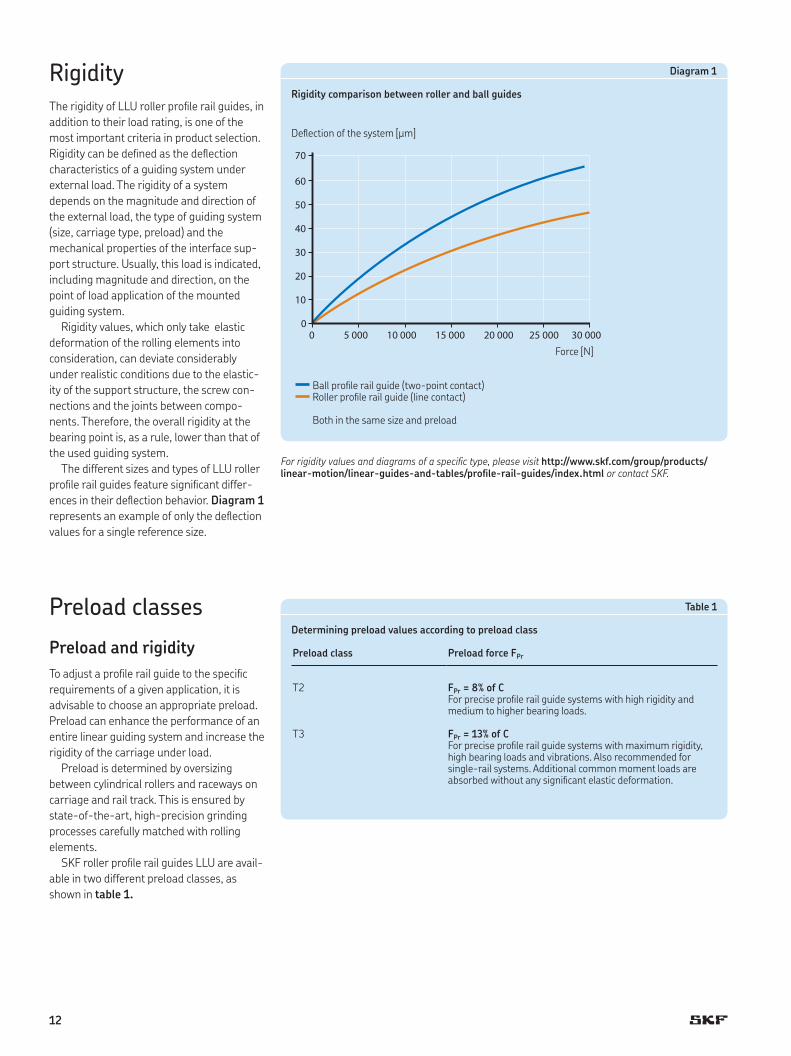
The rigidity of LLU roller proile rail guides, in
addition to their load rating, is one of the
most important criteria in product selection.
Rigidity can be deined as the delection
characteristics of a guiding system under
external load. The rigidity of a system
depends on the magnitude and direction of
the external load, the type of guiding system
(size, carriage type, preload) and the
mechanical properties of the interface sup-
port structure. Usually, this load is indicated,
including magnitude and direction, on the
point of load application of the mounted
guiding system.
Rigidity values, which only take elastic
deformation of the rolling elements into
consideration, can deviate considerably
under realistic conditions due to the elastic-
ity of the support structure, the screw con-
nections and the joints between compo-
nents. Therefore, the overall rigidity at the
bearing point is, as a rule, lower than that of
the used guiding system.
The different sizes and types of LLU roller
proile rail guides feature signiicant differ-
ences in their delection behavior. Diagram 1
represents an example of only the delection
values for a single reference size.
Preload classes
Preload and rigidity
To adjust a proile rail guide to the speciic
requirements of a given application, it is
advisable to choose an appropriate preload.
Preload can enhance the performance of an
entire linear guiding system and increase the
rigidity of the carriage under load.
Preload is determined by oversizing
between cylindrical rollers and raceways on
carriage and rail track. This is ensured by
state-of-the-art, high-precision grinding
processes carefully matched with rolling
elements.
SKF roller proile rail guides LLU are avail-
able in two different preload classes, as
shown in table 1.
60
70
50
40
30
20
10
0
0 5 000 10 000 15 000 20 000 25 000 30 000
Diagram 1
Rigidity comparison between roller and ball guides
Delection of the system [µm]
Force [N]
Ball proile rail guide (two-point contact)Roller proile rail guide (line contact)
Both in the same size and preload
Table 1
Determining preload values according to preload class
Preload class Preload force FPr
T2 FPr = 8% of CFor precise proile rail guide systems with high rigidity and medium to higher bearing loads.
T3 FPr = 13% of CFor precise proile rail guide systems with maximum rigidity, high bearing loads and vibrations. Also recommended for single-rail systems. Additional common moment loads are absorbed without any signiicant elastic deformation.
For rigidity values and diagrams of a speciic type, please visit http://www.skf.com/group/products/linear-motion/linear-guides-and-tables/proile-rail-guides/index.html or contact SKF.
13
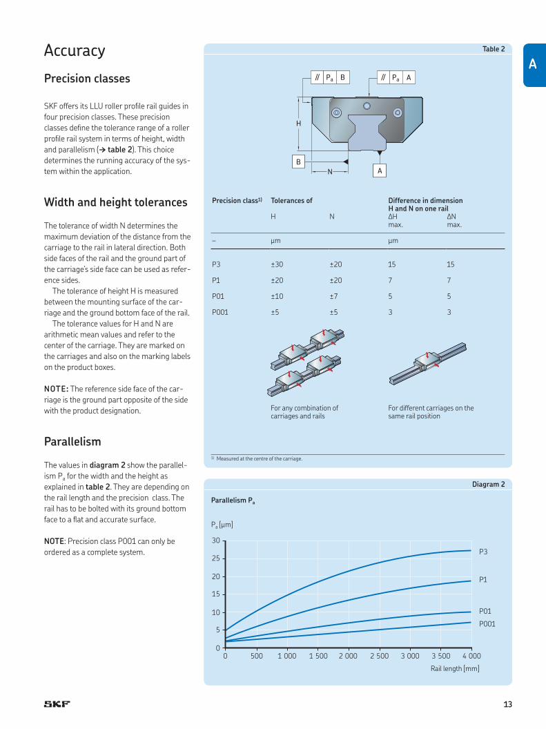
AAccuracy
Precision classes
SKF offers its LLU roller proile rail guides in
four precision classes. These precision
classes deine the tolerance range of a roller
proile rail system in terms of height, width
and parallelism († table 2). This choice
determines the running accuracy of the sys-
tem within the application.
Width and height tolerances
The tolerance of width N determines the
maximum deviation of the distance from the
carriage to the rail in lateral direction. Both
side faces of the rail and the ground part of
the carriage’s side face can be used as refer-
ence sides.
The tolerance of height H is measured
between the mounting surface of the car-
riage and the ground bottom face of the rail.
The tolerance values for H and N are
arithmetic mean values and refer to the
center of the carriage. They are marked on
the carriages and also on the marking labels
on the product boxes.
NOTE: The reference side face of the car-
riage is the ground part opposite of the side
with the product designation.
Parallelism
The values in diagram 2 show the parallel-
ism Pa for the width and the height as
explained in table 2. They are depending on
the rail length and the precision class. The
rail has to be bolted with its ground bottom
face to a lat and accurate surface.
NOTE: Precision class P001 can only be
ordered as a complete system.
Table 2
Precision class1) Tolerances of Difference in dimension H and N on one rail
H N ∆H ∆Nmax. max.
– μm μm
P3 ±30 ±20 15 15
P1 ±20 ±20 7 7
P01 ±10 ±7 5 5
P001 ±5 ±5 3 3
For any combination of carriages and rails
For different carriages on the same rail position
1) Measured at the centre of the carriage.
A
H
APa//BPa//
B
N
10
15
25
30
20
5
00
1 000500 1 500 2 000 2 500 3 5003 000 4 000
Diagram 2
Parallelism Pa
Pa [µm]
P3
P1
P01
P001
Rail length [mm]

14
Permissible operating conditions
The function of LLU roller proile rail guides
can be realized only if there are no deviations
from the speciied operating conditions. The
formulae and life values stated in the chap-
ter calculation bases († page 15) are valid
only if the operating conditions described in
the following are adhered to.
Dynamic values
LLU roller proile rail guides can reach a
maximum speed of vmax = 3 m/s.
The maximum acceleration is
amax = 50 m/s2.
Required minimum load
To prevent the rolling elements from sliding
in the load zone during operation, a linear
guide must be under a minimum load at all
times. Because the LLU carriage is always
preloaded, this minimum load is provided by
its design principle. Thus it does not specii-
cally have to be considered for the applica-
tion by the user.
Permissible maximum load
When selecting a LLU roller proile rail guide,
the dynamic and static load ratings are key
factors in this process.
For example, the equivalent dynamic
mean load Pm during operation must not
exceed 50% of the dynamic load rating. To
calculate the dynamic bearing load,
see page 17.
Exceeding the dynamic load ratings in
operation results in a deviation of the usual
load distribution and can signiicantly reduce
bearing service life. A statistical evaluation
according to the Weibull distribution (contin-
uous probability distribution) is not reliable
in these cases.
As stated in ISO 14728 Part 2, the maxi-
mum load should not exceed 50% of the
static load rating C0.
Standstill
When external forces create vibrations in a
stationary LLU roller proile rail guide, sur-
face damage due to micro-movements
between the cylindrical rollers and raceways
may occur. This can increase noise levels
during dynamic operation and reduce sys-
tem service life.
To avoid this type of damage, the guides
should be isolated from external vibration
and mechanically unloaded for transport
purposes.
Permissible operating temperatures
The permissible temperature range for LLU
roller proile rail guides is:
Continuous operation: –10 to +80 °C
This temperature range is determined by the
synthetic materials used for the end plates,
recirculations and seals.
The time limit for the permissible maxi-
mum temperature is dependent on the
actual operating conditions. Low speed
(< 0,2 m/s), slightly loaded (P < 15% C) or
stationary applications can be exposed to an
ambient temperature of < 100 °C for up to
one hour. Design measures, such as heat
shielding can extend this period.
Be sure to check prior to use that the tem-
perature limits of the lubricant can with-
stand elevated temperatures.
Friction
In addition to the external operating load,
the friction in a guiding system is determined
by a number of other factors: the preload
class, the speed of travel, the viscosity of the
lubricant, etc. should be taken into
consideration.
The displacement resistance is deter-
mined by the proportions of rolling and slid-
ing friction generated by the rolling elements
in the contact zone. Also, the recirculation
geometry as well as the lubricant has an
inluence.
The effect of the lubricant depends on its
characteristics, quantity and condition.
A running-in phase provides a better dis-
tribution of the lubricant in the carriage, and
therefore reduces friction.
The operating temperature of the guiding
system also inluences friction. Higher tem-
peratures reduce the viscosity of the
lubricant.
Another factor is the sliding friction of the
front and longitudinal seals in contact with
the proile rail guide. The friction generated
by the seals will, however, decrease after the
running-in phase.
Moreover, the mounting accuracy of the
rails relative to each other plays an impor-
tant part, just like the latness of both the
mounting and the base plate.
The coeficient of friction for lubricated
roller proile rail guides is typically between
µ = 0,004 and 0,006. Lower values should
be selected for higher loads, and higher val-
ues for lower loads. The friction values of the
seals must be added to these values and can
be made available upon request.
Lubrication
Two different lubrication methods are avail-
able for LLU: grease and oil lubrication.
In addition, LLU roller carriages and rails
are protected with high-quality anti-corro-
sion preservation oil for transport, storage
and mounting. This special oil supports ini-
tial installation of LLU and can remain in the
product if the SKF recommended lubricants
are used. For more information, see
page 49.

15
ACalculation bases
The calculation methods described in this
chapter must take into account all actual
loads and forces acting on the individual
carriages.
Static safety factor
The static safety factor is expressed as the
relationship between the static load rating
and the maximum static bearing load
including preload († page 16). The load
conditions († page 19) acting on the guiding
system during operation must also be taken
into account. The static safety factor indi-
cates the level of safety against permanent
plastic deformation of the rolling elements
and raceways and is calculated according
to formula 2.
C0 C0(2) s0 = — = ———— P0 fd Fres max
where
C0 = static load rating [N]
fd = factor for load conditions
Fres max = maximum resulting load [N]
P0 = maximum static load [N]
s0 = static safety factor
Based on practical experience, guideline
values have been speciied for the static
safety factor, which depend on the operating
mode and other external factors. See
table 3.
If, for example, the guiding system is
exposed to vibrations from the machining
process, higher safety factors should be
applied. Moreover, the load transfer paths
between a proile rail guide and its support
structure should be taken into account. In
particular, the bolted connections must be
examined for suficient safety. See also the
chapter Mounting and maintenance
(† page 44). For overhead installations of
LLU roller proile rail guides, higher safety
factors should be applied. In any case, all
provided attachment holes in carriage and
rail are to be used in the application to make
sure that loads applied on the linear guide
will safely be taken and transferred.
NOTE: The maximum resulting load Fres max
should be calculated based on the combined
static bearing load Fcomb stat determined
according to the chapter Combined static
bearing load, on page 16.
NOTE: The general technical rules and
standards in the respective industrial sector
must also be observed.
Basic rating life L10
Under controlled laboratory conditions,
seemingly identical bearings operating
under identical conditions have different
individual endurance lives. A clearer deini-
tion of the term “bearing life” is therefore
essential to calculate bearing size as outlined
in Basic rating life at constant speed..
IMPORTANT: All information presented by
SKF with regard to load ratings is based on
the life that 90% of a suficiently large group
of apparently identical bearings can be
expected to attain or exceed.
Basic rating life at constant speed
If the speed is constant, the basic rating life,
L10s or L10h, can be calculated
using formulae 3 and 5:
C 10
(3) L10s = (—) 3
100 P
(4)
5 × 10⁷ C 10
(5) L10h = ——— (—) 3
S n 60 P
where
C = dynamic load rating [N]
fd = factor for load conditions
fi = factor for number of carriages per rail
Fres = resulting load [N]
L10h = basic rating life [h]
L10s = basic rating life [km]
n = stroke frequency [double strokes/min]
P = equivalent dynamic load [N]
fs = factor for stroke length
S = single stroke length [mm]
Applying a preload
Depending on the combined bearing load
and preload class, the resulting load has to
be calculated according to the following
methodology to get the impact on the life of
LLU roller proile rail guides.
Load case 1
Fcomb ≤ 2,8 FPr (FPr † table 1)
Fcomb(6) Fres = (——— +1) 1,5
FPr 2,8 FPr
Load case 2
Fcomb > 2,8 FPr (FPr † table 1)
(7) Fres = Fcomb
where
Fcomb = combined, static or dynamic
bearing load [N]
FPr = preload force [N]
Fres = resulting load [N]
Table 3
Static safety factor depending on operating conditions
Operating conditions s0
Normal conditions min. 2Smooth, vibration-free operation >2–4Medium vibrations or impact loads 3–5High vibrations or impact loads >5Overhead installations The general technical rules and standards in the respective
industrial sector must be observed. And if the application poses a risk of serious injury, the user must take appropriate design and safety measures that will prevent the carriage from becoming detached from the rail (e.g. due to loss of roll-ing elements or failure of screw connections).
P= �res
———
fd
fi
fs
—3
10—
16
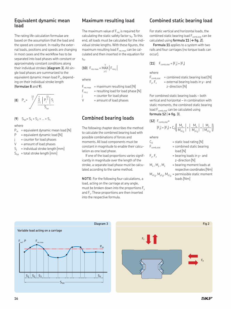
Equivalent dynamic mean load
The rating life calculation formulae are
based on the assumption that the load and
the speed are constant. In reality the exter-
nal loads, positions and speeds are changing
in most cases and the worklow has to be
separated into load phases with constant or
approximately constant conditions along
their individual strokes (diagram 3). All sin-
gle load phases are summarized to the
equivalent dynamic mean load Pm depend-
ing on their individual stroke length
(formulae 8 and 9).
(8)
(9) Stot = S1 + S2 + … + Sv
where
Pm = equivalent dynamic mean load [N]
P = equivalent dynamic load [N]
j = counter for load phases
V = amount of load phases
Sj = individual stroke length [mm]
Stot = total stroke length [mm]
Maximum resulting load
The maximum value of Fres is required for
calculating the static safety factor s0. To this
end, all loads must be calculated for the indi-
vidual stroke lengths. With these igures, the
maximum resulting load Fres max can be cal-
culated and then inserted in the equation for
s0.
V
(10) Fres max = MAX | Fres,j | j=1
where
Fres max = maximum resulting load [N]
Fres,j = resulting load for load phase [N]
j = counter for load phase
V = amount of load phases
Combined bearing loads
The following chapter describes the method
to calculate the combined bearing load with
possible combinations of forces and
moments. All load components must be
constant in magnitude to enable their calcu-
lation as one load phase.
If one of the load proportions varies signif-
icantly in magnitude over the length of the
stroke, a separate load phase must be calcu-
lated according to the same method.
NOTE: For the following four calculations, a
load, acting on the carriage at any angle,
must be broken down into the proportions Fy
and Fz. These proportions are then inserted
into the respective formula.
Combined static bearing load
For static vertical and horizontal loads, the
combined static bearing load Fcomb,stat can be
calculated using formula 11 († ig. 2).
Formula 11 applies to a system with two
rails and four carriages (no torque loads can
occur).
(11) Fcomb,stat = |Fy| + |Fz|
where
Fcomb,stat = combined static bearing load [N]
Fy, Fz = external bearing loads in y- and
z-direction [N]
For combined static bearing loads – both
vertical and horizontal – in combination with
static moments, the combined static bearing
load Fcomb,stat can be calculated using
formula 12 († ig. 3).
where
C0 = static load rating [N]
Fcomb,stat = combined static bearing
load [N]
Fy, Fz = bearing loads in y- and
z-direction [N]
Mx , My , Mz = bearing moment loads at
respective coordinates [Nm]
MxC0, MyC0
, MzC0 = permissible static moment
loads [Nm]
(12) F comb,stat= Mx My Mz |Fy| + |Fz| + C0 (| —— | + | —— | + | —— |) MxC0
MyC0 MzC0
Fres
, P Fres max
Pm
S1 S2 S3 SV
Stot
Fz
Fy
Diagram 3
Variable load acting on a carriage
Fig 2
Pj3
10—
3
10—
oj=1 aa aaSj
V
Pm=
Stot
—————
—————

17
AFormula 12 can be used for the following
systems:
• One rail with one carriage (all types of
moment loads can occur)
• Two rails with one carriage each (Mx can-
not occur)
• One rail with two carriages (My, Mz cannot
occur)
NOTE: The maximum value of Fcomb,stat is
required for calculating the static safety fac-
tor s0. To this end, all loads must be calcu-
lated for the individual stroke lengths. With
these igures, the maximum resulting load
Fres max can be calculated and then inserted in
the equation for s0.
Combined dynamic bearing load
For loads – both vertical and horizontal
(† ig. 2) – the combined dynamic bearing
load Fcomb,dyn is calculated by means
of formula 13. Formula 13 applies to a sys-
tem with two rails and four carriages.
(13) Fcomb,dyn = |Fy| + |Fz|
where
Fcomb,dyn = combined dynamic bearing
load [N]
Fy, Fz = bearing loads in y- and
z-direction [N]
NOTE: The design of the proile rail guide
permits this simpliied calculation. If different
load phases exist for Fy and Fz, then Fy and Fz
must be considered individually in
formula 8.
When combined dynamic bearing loads and
dynamic moments are present, the com-
bined dynamic bearing load Fcomb,dyn can be
calculated using formula 14 († ig. 3) .
where
C = dynamic load rating [N]
Fcomb,dyn = combined dynamic bearing
load [N]
Fy, Fz = bearing loads in y- and z-di-
rection [N]
Mx, My, Mz = bearing moment loads at
respective coordinates [Nm]
MxC, MyC, MzC = permissible dynamic
moment loads [Nm]
Formula 14 can be used for the following
systems:
• One rail with one carriage (all types of
moment loads can occur)
• Two rails with one carriage each (Mx can-
not occur)
• One rail with two carriages (My, Mz cannot
occur)
(14) F comb,dyn= Mx My Mz |Fy| + |Fz| + C (| —— | + | —— | + | —— |) MxC MyC MzC
x
Fz
Mz
Mx
Fy
yFy
My
z
Fig 3

18
Factors of influence
Requisite reliability
Factor c1 is used for lifetime calculations
where reliability higher than 90% is needed.
The corresponding values can be found in
(† table 4).
Operating conditions
The lubrication effectiveness is strongly
dependent on the degree of separation
between the rolling elements and raceway
surfaces in the contact zones. A speciic min-
imum viscosity is required for the formation
of an effectively separating lubricating ilm at
operating temperature, taking into account
the kinematic conditions. Assuming a normal
level of cleanliness of the proile rail guide as
well as effective sealing, factor c2 depends
on the viscosity ratio κ exclusively. κ desig-
nates the ratio between the actual kinematic
viscosity and the requisite minimum viscos-
ity († formula 15).
ν(15) κ = — ν1
where
κ = viscosity ratio
ν = actual kinematic viscosity [mm2/s]
ν1 = requisite minimum viscosity [mm2/s]
The requisite minimum viscosity ν1 for LLU
guides depends on the mean speed
(† diagram 4).
The value for ν1 can be related to the actual
viscosity ν according to formula 15 in order
to obtain κ. Now c2 can be taken from the
following diagram († diagram 5). If the vis-
cosity ratio κ is less than 1, a lubricant with
EP additives is recommended. If lubricant
with EP additives is used, the higher value
for c2 can be used for calculation.
10 000
1 000
100
10
1 10 100 1 000 10 000
v1 [mm2/s]
v [mm/s]
1,2
1,0
0,8
0,6
0,4
0,2
0 0,1 0,2 0,3 0,4 0,5 0,6 0,7 0,8 0,9 1,0 1,1
c2
k = n/n1
Diagram 4
Determining the requisite minimum viscosity ν1
Diagram 5
Determining factor c2 for operating conditions
Table 4
Factor c1 for reliability
Reliability % Lns C1
90 L10s 195 L5s 0,6296 L4s 0,5397 L3s 0,4498 L2s 0,3399 L1s 0,21
19
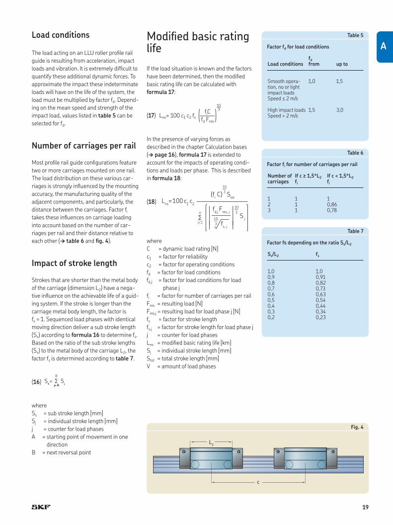
ALoad conditions
The load acting on an LLU roller proile rail
guide is resulting from acceleration, impact
loads and vibration. It is extremely dificult to
quantify these additional dynamic forces. To
approximate the impact these indeterminate
loads will have on the life of the system, the
load must be multiplied by factor fd. Depend-
ing on the mean speed and strength of the
impact load, values listed in table 5 can be
selected for fd.
Number of carriages per rail
Most proile rail guide conigurations feature
two or more carriages mounted on one rail.
The load distribution on these various car-
riages is strongly inluenced by the mounting
accuracy, the manufacturing quality of the
adjacent components, and particularly, the
distance between the carriages. Factor fi
takes these inluences on carriage loading
into account based on the number of car-
riages per rail and their distance relative to
each other († table 6 and ig. 4).
Impact of stroke length
Strokes that are shorter than the metal body
of the carriage (dimension L2) have a nega-
tive inluence on the achievable life of a guid-
ing system. If the stroke is longer than the
carriage metal body length, the factor is
fs = 1. Sequenced load phases with identical
moving direction deliver a sub stroke length
(Ss) according to formula 16 to determine fs.
Based on the ratio of the sub stroke lengths
(Ss) to the metal body of the carriage L2, the
factor fs is determined according to table 7.
(16)
where
Ss = sub stroke length [mm]
Sj = individual stroke length [mm]
j = counter for load phases
A = starting point of movement in one
direction
B = next reversal point
Modified basic rating life
If the load situation is known and the factors
have been determined, then the modiied
basic rating life can be calculated with
formula 17:
fiC 10
(17) Lns= 100 c1 c2 fs (——–) 3
fd Fres
In the presence of varying forces as
described in the chapter Calculation bases
(† page 16), formula 17 is extended to
account for the impacts of operating condi-
tions and loads per phase. This is described
in formula 18:
(18)
where
C = dynamic load rating [N]
c1 = factor for reliability
c2 = factor for operating conditions
fd = factor for load conditions
fd,j = factor for load conditions for load
phase j
fi = factor for number of carriages per rail
Fres = resulting load [N]
Fres,j = resulting load for load phase j [N]
fs = factor for stroke length
fs,j = factor for stroke length for load phase j
j = counter for load phases
Lns = modiied basic rating life [km]
Sj = individual stroke length [mm]
Stot = total stroke length [mm]
V = amount of load phases
Lns= 100 c
1 c2
oV
j=1 fs, j
S j
fd,j Fres, j
(fi C) S
tot
3
10—
3
3
10—
Table 7
Factor fs depending on the ratio Ss/L2
Ss/L2 fs
1,0 1,00,9 0,910,8 0,820,7 0,730,6 0,630,5 0,540,4 0,440,3 0,340,2 0,23
c
L2
Table 5
Factor fd for load conditions
fd
Load conditions from up to
Smooth opera-tion, no or light impact loads Speed ≤ 2 m/s
1,0 1,5
High impact loads Speed > 2 m/s
1,5 3,0
Table 6
Factor fi for number of carriages per rail
Number of carriages
If c ≥ 1,5*L2
fi
If c < 1,5*L2
fi
1 1 12 1 0,863 1 0,78
Fig. 4
oj��
S j
B
Ss=

20
Legend
A starting point of movement in one direction
B next reversal point
C dynamic load rating [N]
C0 static load rating [N]
c1 factor for reliability
c2 factor for operating conditions
fd factor for load conditions
fd,j factor for load conditions for load phase j
fi factor for number of carriages per rail
fs factor for stroke length
fs,j factor for stroke length for load phase j
Fy, Fz bearing loads in y- and z-direction [N]
Fcomb,stat combined static bearing load [N]
Fcomb,dyn combined dynamic bearing load [N]
Fcomb combined static or dynamic bearing load [N]
FPr preload force [N]
Fres resulting load [N]
Fres,j resulting load for load phase j [N]
Fres max maximum resulting load [N]
j counter for load phases [N]
κ viscosity ratio
L10h basic rating life [h]
L10s basic rating life [km]
Lns modiied basic rating life [km]
Mx, My, Mz bearing moment loads at respective coordinates [Nm]
MxC, MyC, MzC permissible dynamic moment loads [Nm]
MxC0, MyC0
, MzC0 permissible static moment loads [Nm]
n stroke frequency [double strokes/min]
ν actual kinematic viscosity [mm2/s]
ν1 requisite minimum viscosity [mm2/s]
P equivalent dynamic load [N]
Pm equivalent dynamic mean load [N]
P0 maximum static load [N]
s0 static safety factor
Sj individual stroke length [mm]
Ss sub stroke length [mm]
Stot total stroke length [mm]
t1, t2 … tn time proportions for v1, v2 … vn [%]
v1, v2 … vn speed [m/min]
vm mean speed [m/min]
V amount of load phases

21
A

22
SKF calculation program
Details pertaining to all the relevant load
situations and the speciication of the gen-
eral design conditions are crucial for pre-
cisely calculating the life expectancy and
static load safety of an LLU roller proile rail
guide system in a speciic application. Ulti-
mately, this information determines the size
and carriage type of the LLU roller proile rail
guide. This design process can be quite
extensive for complex applications. There-
fore, SKF offers the “linear guide calculator”
program, which is available at www.skf.com.
This calculation program supports the user
and is extremely effective in the design of
LLU roller proile rail guide systems.
The following information must be available
prior to starting a calculation:
• number of load phases
• moved masses as well as operating loads
including coordinates
• stroke length of single load phases
• reaction forces accommodated by the
drive system (in the direction of travel)
• selection of preload applied to the guide
• layout (number of rails and carriages)
• geometry of linear axis (distance between
rails relative to each other and carriages
relative to each other)
To supply the details needed to select your
proile rail guides, please complete the speci-
ication sheet found on pages 58–61 of this
publication.
NOTE: If the user is free to select the appli-
cation coordinate system, SKF recommends
using the coordinate system in the program.
This facilitates the analysis of all operating
loads and the resulting reaction forces in the
carriages and prevents transformation
errors.
Representation of results
When the calculation routine is complete,
the user will receive the following data in a
clearly structured form:
• all input data
• load values per carriage in the y- and
z-direction and moment loads for all con-
ceivable load phases
• calculation of maximum resulting load and
equivalent dynamic mean load per
carriage
• basic rating life of carriages
• static safety factor of carriages
Depending on the expected life or static
safety factor, various carriage sizes can be
selected for printout.
LLUHC 35 A T2
LLUHC 35 A T2
LLUHC 35 A T2
LLUHC 35 A T2
LLUHC 35 A T2
LLUHC 35 A T2
d
c
c
+Fz /+z
+Fy /+y +Fx /+x
+Fy /+y +Fx /+x
+Fz /+z

23
AProduct data
LLUHC … AFlanged carriageStandard length, standard heightFurther information on page 26
LLUHR...D8Proile rail with steel hole plugsFurther information on page 34
LLUHR...D6Proile rail with brass hole plugsFurther information on page 34
LLUHC … LAFlanged carriageExtended length, standard heightFurther information on page 28
LLUHR...D4Proile rail with blind holesFurther information on page 34
LLUHC … RSlim-line carriageStandard length, extended heightFurther information on page 30
LLUHC … LRSlim-line carriageExtended length, extended heightFurther information on page 32
LLUHR...Proile rail with standard hole capsFurther information on page 34

24
LLUHC … AFlanged carriage, standard length, standard height
Size Load ratingsC C0
– N
25 27 000 57 60035 53 300 99 00045 95 000 184 000
55 132 600 256 00065 212 000 414 000
LLUHC … RSlim-line carriage, standard length, extended height
Size Load ratingsC C0
– N
25 27 000 57 60035 53 300 99 00045 95 000 184 000
55 132 600 256 00065 212 000 414 000
LLUHC … LRSlim-line carriage, extended length, extended height
Size Load ratingsC C0
– N
25 36 500 76 80035 72 600 136 00045 119 500 242 200
55 176 000 351 00065 276 000 579 000
LLUHC … LAFlanged carriage, extended length, standard height
Size Load ratingsC C0
– N
25 36 500 76 80035 72 600 136 00045 119 500 242 200
55 176 000 351 00065 276 000 579 000
Product dataCarriages
Pages 26–33

25
B
Rails
Pages 34–35
LLUHR rails
Standard rail, always supplied with protec-
tive plastic caps for mounting from above.
LLUHR … D4 rails
With blind holes for mounting from below.
LLUHR … D6 rails
Standard rail supplied with protective brass
plugs for mounting from above.
LLUHR … D8 rails
Standard rail supplied with protective steel
plugs for mounting from above.

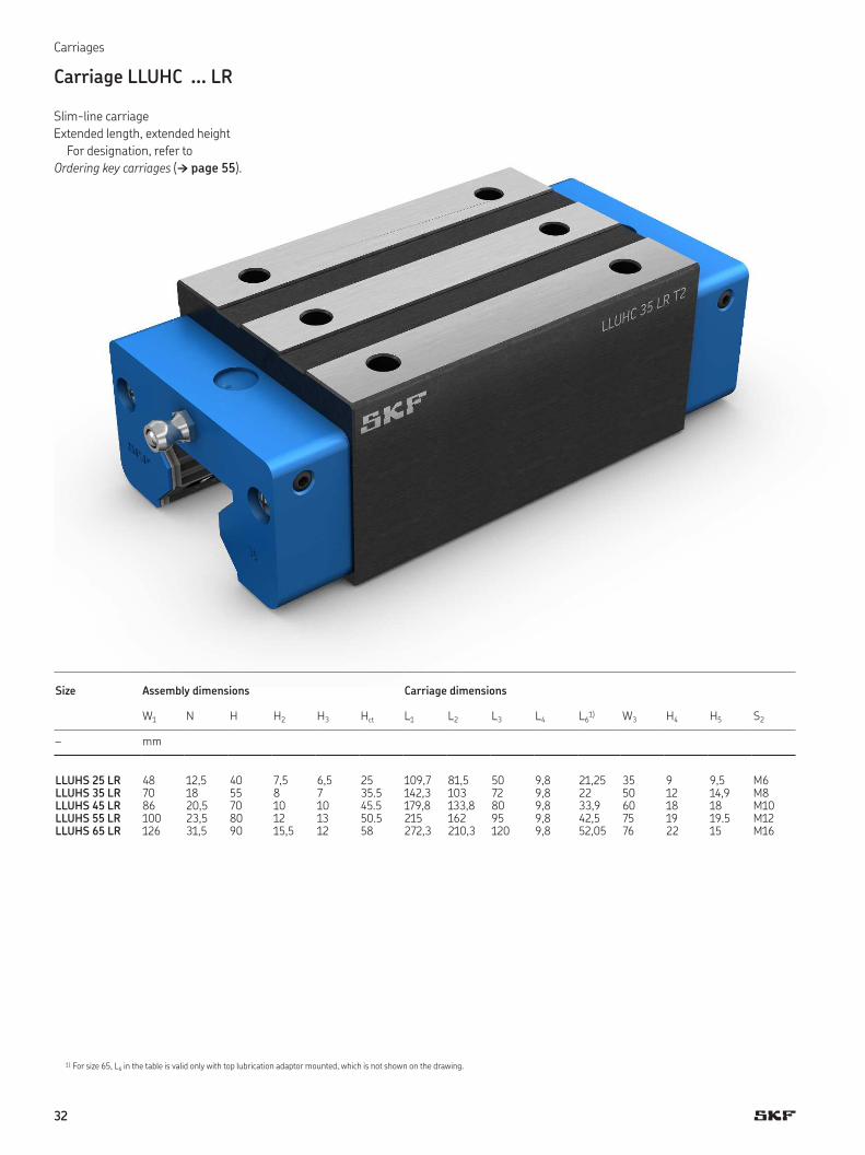
26
Carriage LLUHC … A
Flanged carriage
Standard length, standard height
For designation, refer to
Ordering key carriages († page 55).
Carriages
Size Assembly dimensions Carriage dimensions
W1 N H H2 H3 Hct L1 L2 L3 L4 L5 L61) W3 H4 H5 H7 D3 D4 S2
– mm
LLUHS 25 A 70 23,5 36 7,5 6,5 21 90,2 62 45 9,8 40 14 57 9 5,5 6,5 6,8 11 M8LLUHS 35 A 100 33 48 8 7 28.5 119,3 80 62 9,8 52 15,5 82 12 7,9 10 8,5 15 M10LLUHS 45 A 120 37,5 60 10 10 35.5 147,3 101,3 80 9,8 60 17,65 100 15 8 12 10,5 18 M12LLUHS 55 A 140 43,5 70 12 13 40.5 173 120 95 9,8 70 21,5 116 18 9,5 13,5 12,5 20 M14LLUHS 65 A 170 53,5 90 15,5 12 58 221,8 159,8 110 9,8 82 31,8 142 22 15 19,5 14,5 23 M16
1) For size 65, L6 in the table is valid only with top lubrication adaptor mounted, which is not shown on the drawing.

27
B
D2
L2
F
L5
EStd
L3L6
W3
D1
L
L4H5
H6H1
H
H2
Hct
Ref. sideH7 (2x)(2x) H4 (4x)
H3 N W
D4 (6x)
D3 (6x)
S2 (6x)W1
L1
Size Rail dimensions Weight Load ratings Momentscarriage rail dynamic static dynamic static dynamic static
W H1 H6 F D1 D2 EStd C C0 MxC MxC0MyC = MzC MyC0 = MzC0
– mm kg kg/m kN Nm
LLUHS 25 A 23 24,35 12,85 30 7 11 12,5 0,7 3,4 27,0 57,6 431 863 285 570LLUHS 35 A 34 32 15 40 9 15 17,5 1,7 6,5 53,3 99,0 1 179 2 192 674 1 253LLUHS 45 A 45 39,85 20,85 52,5 14 20 23,75 3,3 10,7 95,0 184,0 2 617 5 070 1 538 2 979LLUHS 55 A 53 47,8 25,8 60 16 24 27,5 5,1 15,2 132,6 256,0 4 503 8 707 2 576 4 981LLUHS 65 A 63 55 29 75 18 26 35 9,3 22,5 212,0 414,0 8 100 15 780 5 210 10 140

28
Carriage LLUHC … LA
Flanged carriage
Extended length, standard height
For designation, refer to
Ordering key carriages († page 55).
Carriages
Size Assembly dimensions Carriage dimensions
W1 N H H2 H3 Hct L1 L2 L3 L4 L5 L61) W3 H4 H5 H7 D3 D4 S2
– mm
LLUHS 25 LA 70 23,5 36 7,5 6,5 21 109,7 81,5 45 9,8 40 23,75 57 9 5,5 6,5 6,8 11 M8LLUHS 35 LA 100 33 48 8 7 28.5 142,3 103 62 9,8 52 27 82 12 7,9 10 8,5 15 M10LLUHS 45 LA 120 37,5 60 10 10 35.5 179,8 133,8 80 9,8 60 33,9 100 15 8 12 10,5 18 M12LLUHS 55 LA 140 43,5 70 12 13 40.5 215 162 95 9,8 70 42,5 116 18 9,5 13,5 12,5 20 M14LLUHS 65 LA 170 53,5 90 15,5 12 58 272,3 210,3 110 9,8 82 57,1 142 22 15 19,5 14,5 23 M16
1) For size 65, L6 in the table is valid only with top lubrication adaptor mounted, which is not shown on the drawing.

29
B
D2
D1
L
L4H5
H6
H1
L1
L2
F
L5
L3 L6
W3
EStd
H
H2
Hct
H7 (2x) H4 (4x)
H3 N W
D4 (6x)
W1S2 (6x)
D3 (6x)Ref. side
Size Rail dimensions Weight Load ratings Momentscarriage rail dynamic static dynamic static dynamic static
W H1 H6 F D1 D2 EStd C C0 MxC MxC0MyC = MzC MyC0 = MzC0
– mm kg kg/m kN Nm
LLUHS 25 LA 23 24,35 12,85 30 7 11 12,5 0,9 3,4 36,5 76,8 583 1 150 491 970LLUHS 35 LA 34 32 15 40 9 15 17,5 2,2 6,5 72,6 136,0 1 595 3 014 1 187 2 243LLUHS 45 LA 45 39,85 20,85 52,5 14 20 23,75 4,3 10,7 119,5 242,2 3 293 6 672 2 444 4 951LLUHS 55 LA 53 47,8 25,8 60 16 24 27,5 7,0 15,2 176,0 351,0 5 977 11 915 4 470 8 910LLUHS 65 LA 63 55 29 75 18 26 35 13,5 22,5 276,0 579,0 10 530 22 100 8 980 11 840

30
Carriage LLUHC … R
Slim-line carriage
Standard length, extended height
For designation, refer to
Ordering key carriages († page 55).
Carriages
Size Assembly dimensions Carriage dimensions
W1 N H H2 H3 Hct L1 L2 L3 L4 L61) W3 H4 H5 S2
– mm
LLUHS 25 R 48 12,5 40 7,5 6,5 25 90,2 62 35 9,8 19 35 9 9,5 M6LLUHS 35 R 70 18 55 8 7 35.5 119,3 80 50 9,8 21,5 50 12 14,9 M8LLUHS 45 R 86 20,5 70 10 10 45.5 147,3 101,3 60 9,8 27,65 60 18 18 M10LLUHS 55 R 100 23,5 80 12 13 50.5 173 120 75 9,8 31,5 75 19 19.5 M12LLUHS 65 R 126 31,5 90 15,5 12 58 221,8 159,8 70 9,8 51,8 76 22 15 M16
1) For size 65, L6 in the table is valid only with top lubrication adaptor mounted, which is not shown on the drawing.

31
B
H5 L4
L1
L
H6
D2
D1
L2
L3 L6
W3
H1
FEStd
H4
H2
Hct
S2 (6x)
N W
W1
H
H3
Ref. side
Size Rail dimensions Weight Load ratings Momentscarriage rail dynamic static dynamic static dynamic static
W H1 H6 F D1 D2 EStd C C0 MxC MxC0MyC = MzC MyC0 = MzC0
– mm kg kg/m kN Nm
LLUHS 25 R 23 24,35 12,85 30 7 11 12,5 0,6 3,4 27,0 57,6 431 863 285 570LLUHS 35 R 34 32 15 40 9 15 17,5 1,6 6,5 53,3 99,0 1 179 2 192 674 1 253LLUHS 45 R 45 39,85 20,85 52,5 14 20 23,75 3,1 10,7 95,0 184,0 2 617 5 070 1 538 2 979LLUHS 55 R 53 47,8 25,8 60 16 24 27,5 4,7 15,2 132,6 256,0 4 503 8 707 2 576 4 981LLUHS 65 R 63 55 29 75 18 26 35 8,5 22,5 212,0 414,0 8 100 15 780 5 210 10 140
32
Carriage LLUHC … LR
Slim-line carriage
Extended length, extended height
For designation, refer to
Ordering key carriages († page 55).
Carriages
Size Assembly dimensions Carriage dimensions
W1 N H H2 H3 Hct L1 L2 L3 L4 L61) W3 H4 H5 S2
– mm
LLUHS 25 LR 48 12,5 40 7,5 6,5 25 109,7 81,5 50 9,8 21,25 35 9 9,5 M6LLUHS 35 LR 70 18 55 8 7 35.5 142,3 103 72 9,8 22 50 12 14,9 M8LLUHS 45 LR 86 20,5 70 10 10 45.5 179,8 133,8 80 9,8 33,9 60 18 18 M10LLUHS 55 LR 100 23,5 80 12 13 50.5 215 162 95 9,8 42,5 75 19 19.5 M12LLUHS 65 LR 126 31,5 90 15,5 12 58 272,3 210,3 120 9,8 52,05 76 22 15 M16
1) For size 65, L6 in the table is valid only with top lubrication adaptor mounted, which is not shown on the drawing.

33
B
L2
L3 L6
W3
FEStd
H4
H2
Hct
H3
S2 (6x)
N W
W1
H
H5 L4L1
H6
D2
D1
L
H1
Ref. side
Size Rail dimensions Weight Load ratings Momentscarriage rail dynamic static dynamic static dynamic static
W H1 H6 F D1 D2 EStd C C0 MxC MxC0MyC = MzC MyC0 = MzC0
– mm kg kg/m kN Nm
LLUHS 25 LR 23 24,35 12,85 30 7 11 12,5 0,8 3,4 36,5 76,8 583 1 150 491 970LLUHS 35 LR 34 32 15 40 9 15 17,5 2,0 6,5 72,6 136,0 1 595 3 014 1 187 2 243LLUHS 45 LR 45 39,85 20,85 52,5 14 20 23,75 4,1 10,7 119,5 242,2 3 293 6 672 2 444 4 951LLUHS 55 LR 53 47,8 25,8 60 16 24 27,5 6,2 15,2 176,0 351,0 5 977 11 915 4 470 8 910LLUHS 65 LR 63 55 29 75 18 26 35 12,7 22,5 276,0 579,0 10 530 22 100 8 980 11 840
34
Rails
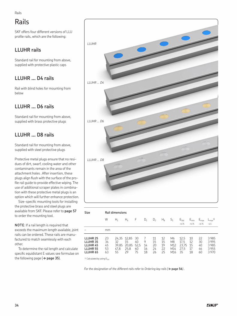
SKF offers four different versions of LLU
proile rails, which are the following:
LLUHR rails
Standard rail for mounting from above,
supplied with protective plastic caps
LLUHR … D4 rails
Rail with blind holes for mounting from
below
LLUHR … D6 rails
Standard rail for mounting from above,
supplied with brass protective plugs
LLUHR … D8 rails
Standard rail for mounting from above,
supplied with steel protective plugs
Protective metal plugs ensure that no resi-
dues of dirt, swarf, cooling water and other
contaminants remain in the area of the
attachment holes . After insertion, these
plugs align lush with the surface of the pro-
ile rail guide to provide effective wiping. The
use of additional scraper plates in combina-
tion with these protective metal plugs is an
option which will further enhance protection.
Size-speciic mounting tools for installing
the protective brass and steel plugs are
available from SKF. Please refer to page 57
to order the mounting tool.
NOTE: If a rail length is required that
exceeds the maximum length available, joint
rails can be ordered. These rails are manu-
factured to match seamlessly with each
other.
To determine the rail length and calculate
speciic equidistant E values see formulae on
the following page († page 35).
Rails
LLUHR
LLUHR ... D4
LLUHR ... D6
LLUHR ... D8
Size Rail dimensions
W H1 H6 F D1 D2 H8 S1 EStd Emin Emax Lmax1)
–0.75 –0.75 –0.75 –1.5
– mm
LLUHR 25 23 24,35 12,85 30 7 11 12 M6 12,5 10 22 3 985LLUHR 35 34 32 15 40 9 15 15 M8 17,5 12 30 3 995LLUHR 45 45 39,85 20,85 52,5 14 20 19 M12 23,75 15 40 3 985LLUHR 55 53 47,8 25,8 60 16 24 22 M14 27,5 17 46 3 955LLUHR 65 63 55 29 75 18 26 25 M16 35 18 60 3 970
1) Calculated by using EStd
For the designation of the different rails refer to Ordering key rails († page 56) .

35
B
FE
L
H6
D2
D1
H1
W
E
F
L
H8
S1
H1
W
E
F
Standard, D6 and D8 rails
D4 rail
Calculation of number of attachment
holes in rail guide
L(1) nreal = — F
(2) Round down of nreal to n
(3) n + 1 = z
F = Distance of attachment holes
L = Rail length
nreal = Real calculation value for number
of hole distances
z = Number of attachment holes in rail
The “E” dimension designates the distance between the end face and the center of the irst mounting hole of the rail.
With sufix “ES” in the ordering key, the holes at both rail ends will be positioned equidistantly from either end of the rail using the EStd dimension.
This results in predeined rail lengths that should be preferred when ordering:
L = nF + 2 EStd
With sufix “E0”, the rail is produced with the shortest possible symmetrical “E” dimension on both rail ends.
With sufix “Exx”, the “E” dimension has to be speciied.
To calculate speciic equidistant “E” dimensions, following formulae are used:
Determination of E dimension based on z
L – F (z – 1)(4) Ereal = ————— 2
Ereal = Real calculation value for
E-dimension
Emin = Minimum E-dimension according to
catalogue
EStd = Standard value for E-Dimension
Comparison with catalogue value of Emin
(4.1) If Ereal ≥ Emin
† Usage of Ereal from formula 4
(4.2) If Ereal < Emin
† Calculation of Ereal according to
formula 5
L – F (z – 2)(5) Ereal = ————— 2

36
Joint rail tracks
If the requested rail length exceeds the avail-
able delivery length of LLU rails, specially
paired and joint rails can be supplied as
ready-to-mount sets consisting of two or
more rails (per rail track). In this case, the
rails are marked on the bottom side
(† ig. 6) in order to avoid mix-up during
mounting († ig. 5). For speciic positions of
the joint(s), please add a drawing. If replace-
ment is required, the complete set should be
exchanged to provide full functionality.
For the proper designation, refer to Order-
ing key rails († page 56).
Fig. 7 shows a tool that simpliies the
mounting procedure of joint rails. It consists
of a c-clamp and two ground shafts.
1A1A
1B1B
2A2A
2B2B
2A2A
2B2B
1B1B
1A1A 1B
1B
2A2A
2B2B
1A1A
Rails
Fig. 7
Fig. 5
Top side of joint rail
Fig. 6
Bottom side of joint rail

37
B
Accessories
Accessories
Item name Illustration1) Purpose
Scraper plateLLUHZ ... S1
Scraper plates are spring-steel, non-contact components. They protect the front seal from coarse contaminants or hot metal chips. Lubrication adaptors can be used without modiications. Longer mounting screws are supplied with the scraper plate.
Additional front sealLLUHZ ... S7LLUHZ ... S4
Additional front seals are contact seals that can be attached to the carriage end faces. They are single-lip seals consisting of special heavy-duty material with rubber (NBR) seal lips (S7) or luoroelastomere (FKM) seal lips (S4). Both offer additional pro-tection against liquids and smaller contaminants. The FKM seal has a better chemical resistance, e.g. against agressive coolants. One lubrication connector and longer screws are supplied with the seal.
Seal kitLLUHZ ... S3LLUHZ ... S8
The seal kit consists of a metal scraper and an additional front seal. It is intended for applications involving exposure to coarse and ine dirt as well as liquids. One lubrication connector and longer screws are supplied with the seal kit.
Lubrication adaptorsLLUHZ VN ...
To connect different lubrication devices to the carriage, several lubrication adaptors are available.
Protective metal plugs from brass or steelLLUHZ ... TD6 / TD8
Metal plugs protect carriage and rail from damagescaused by high thermal and mechanical exposure, e.g. chip formation.
Assembly tool for metal plugsLLUHZ ... D6
Rail size speciic assembly tools are available for proper installa-tion of protective metal plugs. There are two sizes available, one covering the range of size 25-45 and one covering size 45-65.
1) Appearance can vary slightly depending on the size.

38
Scraper plate
LLUHZ ... S1
• Material: Spring steel according to
DIN EN 10088
• Appearance: Steel grey
• Designed with a speciied maximum gap
of ~ 50 µm
Mounting
The standard grease nipple still its. Longer
mounting screws are supplied with the
scraper plate. When mounting, be sure there
is an even space between the rail and
scraper plate.
NOTE: Can be ordered in combination
with an additional front seal as a kit,
designation S3 or S8.
Scraper plate
Appearance can vary slightly depending on the size.
Scraper plate
Carriage size T T2
– mm
25 1 2,635 1 3,345 1,5 455 1,5 4,865 2 8
T
T2
Accessories

39
B
Additional front seal
LLUHZ ... S7
• Material: Elastomer (NBR) on steel carrier
• Design: Single-lip seal
LLUHZ ... S4
• Material: Fluoroelastomer (FKM) on steel
carrier
• Good chemical resistance e.g. against
agressive coolants
• Design: Single-lip seal
Mounting
One lubrication connector and longer
mounting screws are supplied with the seal.
For dimensions of the lubrication connector
please refer to table 8 (→ page 42)
NOTE: Can be ordered in combination
with an additional scraper plate as a kit,
designation S3 or S8.
Additional front seal
Appearance can vary slightly depending on the size.
Additional front seal
Carriage size T T2
– mm
25 6 2,635 6 3,345 6 455 6 4,865 7 8
T2
T

40
Seal kit
LLUHZ ... S3
The seal kit consists of the following
components:
• Scraper plate
• Additional front seal S7 (NBR)
LLUHZ ... S8
The seal kit consists of the following
components:
• Scraper plate
• Additional front seal S4 (FKM)
Mounting
One lubrication connector and longer
mounting screws are supplied with the
seal kit. For dimensions of the lubrication
connector please refer to table 8
(→ page 42).
When mounting, be sure there is an even
space between the rail and scraper plate.
Seal kit
Appearance can vary slightly depending on the size.
Seal kit
Carriage size T T2
– mm
25 7 2,635 7 3,345 7,5 455 7,5 4,865 9 8
Accessories
T2
T

41
B
Lubrication adaptors
All lubrication adaptors are standardized
with a M6 thread for secure attachment to
the carriages of all sizes. For our range of
grease nipples, couplings and ittings, please
refer to table 8.
Grease nipples
Quick couplings
Adapters
Top lubrication
Lubrication adaptors

42
Lubrication adaptors
Accessories
Table 8
Range overview of lubrication adaptors
Dimensions Item name, ordering key Material Comment
Grease nipple straightLLUHZ VN-M6
Steel, coated Is supplied with the carriage as standard.
Grease nipple 45°LLUHZ VN-M6-45
Steel, coated
Grease nipple 90°LLUHZ VN-M6-90
Steel, coated
Quick coupling straightLLUHZ VN SC
Steel, coated To connect 4 mm outer diameter plastic pipe. Max. operating pressure: 30 bar
Quick coupling 90°, adjustableLLUHZ VN AC
Steel, coated Coupling can be rotated 360°. To connect 4 mm outer diameter plastic pipe.Max. operating pressure: 30 bar
Lubrication connectorLLUHZ VN UA
Stainless steel Needed when using seal kit S3, S8 and seal S7, S4.
Reduction ittingLLUHZ VN UB
Stainless steel Reduction from G1/8 to M6 when connec-tion to a pipe system is needed.
Reduction ittingLLUHZ VN UC
Stainless steel Reduction from M8x1 to M6.
Adaptor for top lubricationLLUHZ VN TL
Aluminium and O-rings Supplied with top lubrication option. Separately only if needed as a spare part.
9.8
M6x1
M6x1
16.3
15.3
9
9
9
919
12.5
M6x1
16
∅4 M6x1
10
∅4
23
18
10M6x1
18 12
12M6x1 G 1/8
M6x1
9
11
22
M6x1
18 12
12M6x1 M8x1

43
B
Adaptor for top lubrication
The lube port for top lubrication in the end
plate is usually closed. If needed, it is to be
ordered separately. In this case the carriage
will be delivered with an opened port and the
necessary top lubrication adaptor. Recondi-
tioning of delivered carriages to accommo-
date top lubrication is not possible.
When ordering a system or a single car-
riage with top lubrication, be sure to specify
on which side of the carriage the lubrication
port is needed.
When ordering an adaptor for top lubrication as a spare part, be sure to specify which
carriage type it is needed for.
TL1 for A, LA carriage O-ring (size 25-55), O-ring + adaptor (size 65)
TL2 for R, LR carriage O-ring + adaptor
TLL (on the left side) TLR (on the right side)
TLB (on both sides)

44
Mounting and maintenance
General instructions
The following mounting instructions are
applicable to all carriage types.
To maintain the high precision of SKF
roller proile rail guides LLU, the carriages
must be handled carefully during transport
and assembly.
To provide protection during transport,
storage and assembly, LLU rails and car-
riages are supplied with a corrosion preserv-
ative. This preservative does not need to be
removed if the recommended lubricants are
used.
NOTE: When carriages are shipped without
a rail, they are equipped with a transporta-
tion sleeve to keep the rollers in place. This
transportation sleeve should never be
removed without pushing the carriage onto
a rail.
Also, the carriages should never be
removed from a rail without using a trans-
portation sleeve to keep the rollers in place.
Failure to follow these directions may
result in the rollers falling out of place. If this
happens, the carriages cannot be used
anymore.
Typical mounting examples
Rails
Each rail has ground reference edges on
both sides.
Options for securing the rails laterally
(† igs. 8 and 9)
1 Stop edges
2 Retaining strips
3 Reference edges
NOTE: Rail ends must be chamfered to pre-
vent seal damage during installation. How-
ever, if two rails are to be joined, do not
chamfer either of the mating ends.
Rails that are not laterally ixed must be
installed straight and parallel. SKF recom-
mends using a support strip to maintain the
rail’s position during installation.
Guideline values for the permissible lat-
eral loads for guidings that are not laterally
supported are listed in table 11.
Carriage
Each carriage has one reference side (please
refer to dimension H2 in the drawings of the
carriages) († pages 26 and following).
Options for securing the carriages
laterally († ig. 9)
4 Stop edges
5 Retaining strips
NOTE: If mounted correctly, the carriage
should move easily on the rail when pushed
(moving force depending on preload). During
assembly, secure the carriage to prevent it
from falling.
1
2 2
Fig. 8
Mounting with laterally ixed rails
1
1
42
2 3
5
Fig. 9
Mounting with laterally ixed rail and carriages
1) For detailed information, please download “Mounting Instruction Proile rail guides LLU” at www.skf.com

45
C
Interface design, screw sizes and tightening torques
• The flange-type carriages can be fastened
from above († ig. 11) and below
(† ig. 12). For ixation from below, use
the attachment holes as pass-through
holes for a screw in the next smaller size.
For the two inner attachment holes (O3),
special screws with low head height
according to DIN 6912 must be used.
• The slim-type carriages can be fastened
only from above († ig. 13).
• Rails can be fastened from both above
(† ig. 12 and 13) or below († ig. 11).
All screw dimensions and recommended
lengths are shown in table 9. The correct
tightening torque is critical to the proper
function of the guide system. It is to be con-
sidered according to table 10. If no stop
edge is provided in the adjacent structure,
then the permissible maximum lateral load
per carriage should be considered. Values
can be found in table 11.
R2
R1
H1
H1
O3 O2
O5
H3
O1
O6
O5
O4
H3
Fig. 10
Fig. 12
Fig. 11
Fig. 13
Table 9
Stop edges, corner radii, screw types and sizes per carriage type and fastening direction
Size Dimensions ScrewH1 R1 max R2 max H3 O1
1) O22) O3
3) O44) O5 O6
5)
– mm ISO 4762 ISO 4762 DIN 6912 ISO 4762
25 5 0,8 0,8 10 M8x20 M6x20 M6x16 M6x18 M6x30 M6x2035 6 0,8 0,8 13 M10x25 M8x25 M8x20 M8x25 M8x35 M8x2545 8 0,8 0,8 14 M12x30 M10x30 M10x25 M10x30 M12x45 M12x3055 10 1,0 1,2 20 M14x40 M12x40 M12x30 M12x35 M14x50 M14x4065 10 1,5 1,5 25 M16x45 M14x45 M14x35 M16x40 M16x60 M16x45
Table 10
Recommended tightening torques of mounting screws
Screw strength class
ScrewM6 M8 M10 M12 M14 M16
– Nm
8.8 10 24 48 83 130 20012.9 15 40 81 135 215 265
1) A, LA type, bolted from above2) A, LA type, bolted from below 4 outer screws3) A, LA type bolted from below 2 inner screws
4) R, LR type bolted from above5) Please respect the general recommendations for minimum
thread engagement lengths
Table 11
Maximum lateral load per carriage
Screw strength class
Screws used for mounting in lineCarriage Rail
O1 O2+O3 O4 O5 O6
8.8 19% C 14% C 14% C 6% C 6% C12.9 29% C 22% C 22% C 10% C 10% C

46
Attachment structure for carriages
Attachment structure for rails
Position tolerances of attachment holes
To ensure the interchangeability between
the machine bed and the proile rail guides, it
is necessary to match the positions of the
corresponding attachment holes of all com-
ponents to be mounted. When observing the
tolerances given in the following drawings, it
is not necessary to remachine the machine
bed, in particular with long proile rail guides.
B
W3A
Stop edge
6×
∅ 0,2 A B∅ L3
A
Stop edge
B
W3
L3
L5
6×
∅ 0,2 A B∅
n x F
L
FA
B
∅ 0,2 A B∅
Stop edge
Ref. sideR / LR - carriage
Ref. sideA / LA - carriage

47
C
Permissible height deviation
The values for height deviation are applica-
ble for all carriage types. If the values for
height deviation S1 and S2 are within the
speciied range, the service life of the rail
guide system will not be inluenced.
Permissible height deviation in lateral
direction († table 12)
S1 = d Y
where
s1 = Permissible height deviation [mm]
d = Distance between the rails [mm]
Y = Calculation factor lateral direction
NOTE: The height tolerance H for the car-
riages has to be taken into account. Please
refer to table 2 on page 13. If the difference
S1–2 x tolerance H < 0, a new product selec-
tion is necessary (other preload, precision).
Permissible height deviation in
longitudinal direction († table 13)
S2 = c X
where
S2 = Permissible height deviation [mm]
c = Distance between the carriages [mm]
X = Calculation factor longitudinal direction
NOTE: The maximum difference ∆H for the
carriages has to be taken into account.
Please refer to table 2 on page 13. If the
difference S2 – ∆H < 0, a new product selec-
tion is necessary (other preload, precision).
Table 12
Permissible height deviation in lateral direction
Calculation factor Y for carriages
Calculation factor Preload T2 (8% C) T3 (13% C)
Y 1,7 × 10⁻⁴ 1,2 × 10⁻⁴
Table 13
Permissible height deviation in longitudinal direction on one rail
Calculation factor X for carriages
Calculation factor Standard length Extended length
X 4,5 × 10⁻⁵ 3,5 × 10⁻⁵
d
S1
c
S2

48
Parallelism
The parallelism of mounted rails is meas-
ured on the rails and the carriages.
The values for deviation in parallelism Pa
are applicable to all carriage types. Deviation
in parallelism Pa increases the internal load.
If the values are within the speciied range in
table 14, the service life of the proile rail
guide system will not be inluenced. With
standard mounting, the adjacent structure is
slightly resilient. However, a rigid, high-pre-
cision adjacent structure is required for pre-
cision mounting. In this case, the values in
table 14 must be halved.
Table 14
Deviation in parallelism Pa
Size Pa in relation to preload class [mm] T2 (8% C) T3 (13% C)
25 0,008 0,005
35 0,012 0,008
45 0,014 0,009
55 0,017 0,011
65 0,018 0,011
Pa//
Pa//

49
D
Lubrication
The appropriate type and amount of lubri-
cant is required for rolling bearings to func-
tion reliably. To reduce wear, the lubricant
prevents direct metal-to-metal contact
between the rolling elements and the race-
ways. In addition, the lubricant protects the
carriage from corrosion.
The guiding system can only realize its
optimum operating temperature when a
suitable amount of lubricant to reliably lubri-
cate the roller proile rail guide is applied.
Basically, two different lubrication meth-
ods are available for LLU: grease and oil
lubrication.
Delivery condition from factory
LLU roller carriages and rails are protected
with high-quality anti-corrosion preserva-
tion oil for transport, storage and mounting.
This special oil supports initial installation of
LLU and can remain in the product if the SKF
recommended lubricants are used.
Each carriage is delivered with one
straight grease nipple and has to be initially
lubricated before usage as described on the
next pages.
Lubrication ports
Both end plates of the carriage feature three
lube ports with M6 thread, one in longitudi-
nal and two in 90° orientation to moving
direction (†fig. 14). At delivery these ports
are closed by grub screws. As standard, one
straight grease nipple for manual lubrication
is supplied with the carriage. If needed, the
carriage can be adapted for top lubrication.
The lube port for top lubrication is usually
closed and has to be ordered separately if
required (see ordering key system). In this
case the carriage will be delivered with an
opened port and the necessary adaptor.
Reconditioning of delivered carriages to
accommodate top lubrication is not possible.
For additional lubrication adaptors please
refer to table 8 on page 42.
Fig. 14
Lubrication ports
lubrication port
lubrication port
lubrication port

50
Grease lubrication
Under normal operating conditions, LLU
roller proile rail guides should be lubricated
with grease. The advantage of grease is that
it is more easily retained in the bearing,
which is particularly important when the axis
of travel is inclined or vertical. Moreover, it
contributes to sealing the bearing against
the ingress of liquid contaminants or
humidity.
Base oil viscosity
The viscosity of the lubricating oil in grease
is key to the formation of the hydrodynamic
ilm that separates the rolling elements from
the raceways.
In general, the viscosity of lubricating oils
is based on the low rate at 40 °C. These val-
ues also apply to the mineral base oils con-
tained in lubricating greases.
The base oils of commercially available
rolling bearing greases have viscosity values
between 15 and 500 mm2/s (at 40 °C).
Greases with higher base oil viscosities often
release the oil too slowly to suficiently lubri-
cate bearings.
Consistency class
Lubricating greases are divided into various
consistency classes according to a scale by
the National Institute of Grease Lubrication
(NLGI). These are also relected in
DIN 51 818 and DIN 51 825.
Greases with a metallic soap thickener
with a consistency of 2 or 3 on the NLGI
scale are particularly suitable for use with
LLU roller proile rail guides. The grease con-
sistency should not vary too much with
changing operating temperatures or stress
levels. Greases that soften at higher temper-
atures can leak from the bearing position,
while greases that stiffen at lower tempera-
tures can impede the operation of the linear
guiding system.
Speciic requirements are placed on the
lubricating grease’s purity, composition and
compatibility if the grease is to be used in
special applications.
Temperature range
The temperature range over which a grease
can be used depends largely on the type of
base oil and thickener as well as the
additives.
The low temperature limit, the lowest
temperature at which the grease enables the
bearing to be started up without dificulty, is
largely determined by the type of base oil
and its viscosity. The high temperature limit
is determined by the type of thickener and its
dropping point. The dropping point is the
temperature at which grease changes its
consistency and becomes a luid.
Note that grease will age with increasing
rapidity at higher operating temperatures.
The resulting by-products have a detrimen-
tal effect on the grease’s lubrication proper-
ties and conditions in the rolling contact
zone.
Lubricating greases with synthetic base
oils can be used both at higher and lower
temperatures than lubricants with a mineral
oil base.
Corrosion-inhibiting additives in lubricants
Lubricants typically contain additives to
inhibit corrosion. In addition, the type of
thickener is crucially important in this
regard.
Lithium-base and calcium-soap greases
provide excellent corrosion protection prop-
erties. They are also resistant to water
wash-out.
SKF bearing greases
The assortment of SKF greases has been
developed based on the latest information
about rolling bearing lubrication and has
undergone extensive testing both in the lab-
oratory and under ield conditions. SKF con-
tinuously monitors the quality of its greases
prior to use or sale.
Table 15 lists those SKF greases that are
particularly well-suited for LLU roller proile
rail guides. Additional information and spe-
cial lubricant recommendations are available
from SKF upon request.
Table 15
A selection of SKF rolling bearing greases
Properties Lubricant (designation)
LGEP 2 LGMT 2 LGLT 2 LGFP 2
Thickener Li Li Li Al complex soapBase oil Mineral oil Mineral oil Di-ester oil Medical white oilOperating temperature,°C (steady state)
–20 up to +100 –30 up to +120 –55 up to +110 –20 up to +110
Kinematic viscosity of base oil
200 110 15 130
Consistency class(acc. to NLGI)
2 2 2 2
Temperature range /Application range
EP grease normal low food compatible

51
D
Table 16
Initial grease lubrication quantities
Quantity/carriage LLUHC 25 LLUHC 35 LLUHC 45 LLUHC 55 LLUHC 65
– cm3
A, R 1,9 2,9 5,3 8,4 15LA, LR 2,2 3,7 6,6 10,6 18,9
Table 18
Grease relubrication quantities
Quantity/carriage LLUHC 25 LLUHC 35 LLUHC 45 LLUHC 55 LLUHC 65
– cm3
A, R 0,5 1,2 2,2 3,2 5,9LA, LR 0,6 1,4 2,6 4 7,4
Table 17
Relubrication interval according to applied carriage load
Load ratio C/Fm LLUHC 25 LLUHC 35 LLUHC 45 LLUHC 55 LLUHC 65
≥ < travel interval in km
8 – 800 500 300 200 1005 8 500 300 150 100 503 5 200 150 80 50 252 3 120 80 40 25 15
Initial grease lubrication
LLU roller proile rail guides must be initially
lubricated immediately after installation with
lubricant quantities speciied in table 16.
During lubrication, the carriage should be
moved at least three times’ its length for
better lubricant distribution within the
carriage.
Grease relubrication
The lubrication intervals for LLU roller proile
rail guides depend primarily on the average
running speed, operating temperature and
grease quality. The intervals recommended
for ixed operating conditions are listed in
table 17. For appropriate grease quantity,
refer to table 18. Where contamination, use
of coolants, vibration, shock loads, etc. are
part of the environmental conditions, it is
advisable to reduce relubrication intervals
accordingly.

52
Oil lubrication
When a LLU roller proile rail guide is used
under particular operating conditions, such
as unfavorable load scenarios or limited
access for relubrication, oil lubrication is
advisable.
For small sizes of roller proile rail guides
under heavy load conditions oil lubrication
might be advantageous to extend the service
life in the application.
Oil lubrication can also be advantageous
when a centralized lubrication system is
installed or where there is a need to unify
the lubrication management with other
machine parts, e g drive train or secondary
lubrication points In this case, SKF recom-
mends oil types according to DIN 51517, type
CLP or DIN 51524, type HLP The viscosity
range should cover ISO VG 68 to ISO VG 220.
Initial oil lubrication
Immediately after installation, the carriages
should be lubricated with the oil quantities
speciied in table 19. The quantities are valid
for all carriage types and vary only with the
size. During the illing, the carriage should be
moved at least three times’ its length for
better oil distribution within the carriage.
Oil relubrication
The oil relubrication intervals for LLU roller
proile rail guides depend primarily on the
average running speed, operating tempera-
ture and oil quality. The intervals recom-
mended for ixed operating conditions are
the same as for grease lubrication and are
listed in table 17. The appropriate oil quan-
tity is the same as for initial lubrication
according to table 19. Where contamination,
use of coolants, vibration, shock loads, etc.
are part of the environmental conditions, it is
advisable to reduce relubrication intervals
accordingly.
In case of impulse oil lubrication, the min-
imum quantity per impulse should be 15% of
the values from table 19.
Temperature range
Note that oil will age with increasing
rapidity at higher operating temperatures.
The resulting by-products have a detrimen-
tal effect on the oil’s lubrication properties
and conditions in the rolling contact zone.
Short stroke applications
If the stroke is less than twice the carriage
length, lube ports on both carriage end
plates must be used, each illed equally with
the grease or oil quantity stated for initial
lubrication or relubrication.
Example
• Short stroke application
• Carriage type A
• Size LLUHC 25
• Grease lubrication
Apply 1,9 cm3 into the left and 1,9 cm3 into
the right grease nipple for initial lubrication.
IMPORTANT: To avoid serious damage to
the rail guides, it is important to consider the
miscibility of greases or oils when changing
from one lubricant to another.
Moreover, you must also consider the
possibility of reduced relubrication intervals
and reduced load ratings as well as the pos-
sibility of chemical interaction with synthetic
materials, lubricants and preservatives.
Please refer to the grease and oil manufac-
turer’s instructions. In case of incompatibility
between lubricants employed, the carriages
should be thoroughly cleaned before
regreasing.
Centralized lubrication systems
If the application features a centralized lubri-
cation system using greases with a consist-
ency of 2 or higher on the NLGI scale, con-
tact SKF.
For automatic relubrication systems from
SKF, please contact your local SKF
representative.
Table 19
Initial oil lubrication quantities
Quantity/carriage LLUHC 25 LLUHC 35 LLUHC 45 LLUHC 55 LLUHC 65
– cm3
0,8 1,0 1,4 1,8 3,6

53
D
Maintenance
To avoid dirt from adhering to and being
embedded into the rails, the rails should be
cleaned regularly with a “cleaning stroke”.
SKF recommends a cleaning stroke over the
entire length of the rails twice a day or at
least every eight hours.
Perform a cleaning stroke whenever
switching the machine on or off.
Repairs
If the LLU roller proile rail guide system has
reached the end of its service life and has to
be replaced, SKF recommends replacing the
whole system. Please locate the name of the
ordering key written on the carriage and
measure the rail length and the E-dimen-
sion (the distance from the rail end to the
irst hole) for re-ordering.
Stationary conditions, shipping and storage
If a LLU roller proile rail guide is stationary
for long periods and subjected to vibration
from external sources, micro movement in
the contact zone between rollers and race-
ways will lead to damage of those surfaces.
This damage can result in a signiicant
increase in running noise and premature
failure due to material fatigue. Damage of
this kind should be avoided at all costs, for
instance by isolating the bearings from
external vibration and by taking suitable
precautions during transport.
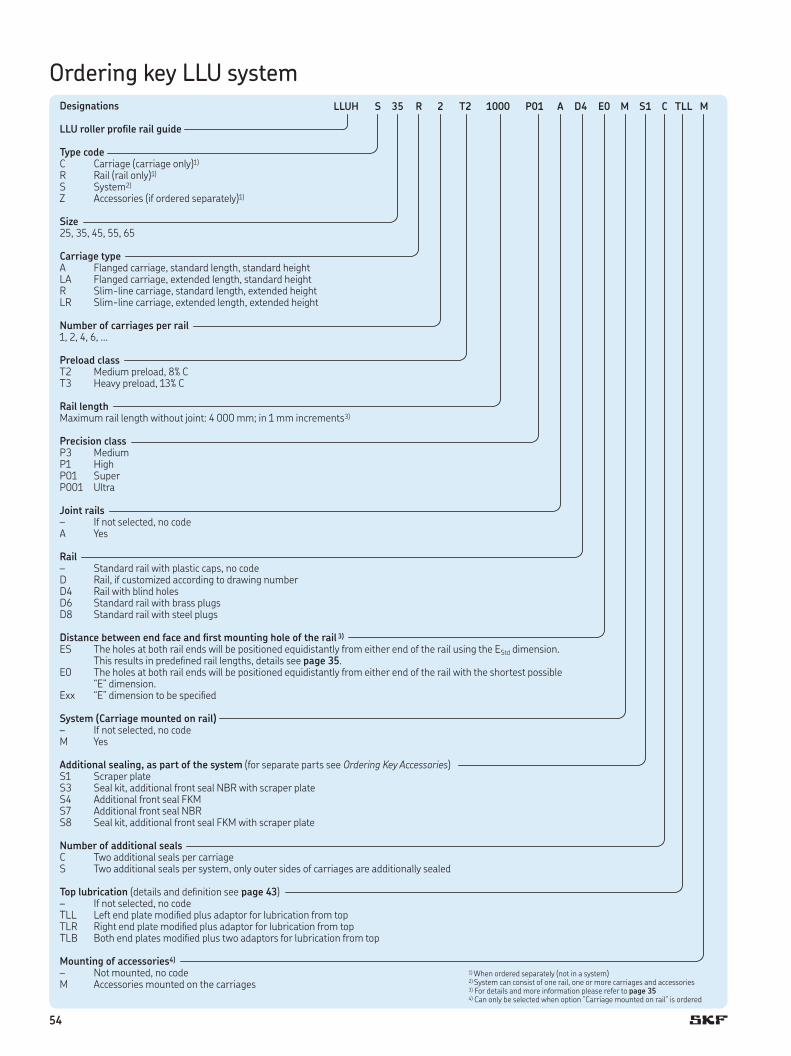
54
1) When ordered separately (not in a system)2) System can consist of one rail, one or more carriages and accessories3) For details and more information please refer to page 354) Can only be selected when option ”Carriage mounted on rail” is ordered
Designations
LLU roller proile rail guide
Type codeC Carriage (carriage only)1)
R Rail (rail only)1)
S System2)
Z Accessories (if ordered separately)1)
Size 25, 35, 45, 55, 65
Carriage typeA Flanged carriage, standard length, standard heightLA Flanged carriage, extended length, standard heightR Slim-line carriage, standard length, extended heightLR Slim-line carriage, extended length, extended height
Number of carriages per rail1, 2, 4, 6, …
Preload classT2 Medium preload, 8% CT3 Heavy preload, 13% C
Rail lengthMaximum rail length without joint: 4 000 mm; in 1 mm increments3)
Precision classP3 MediumP1 HighP01 SuperP001 Ultra
Joint rails– If not selected, no codeA Yes
Rail– Standard rail with plastic caps, no codeD Rail, if customized according to drawing numberD4 Rail with blind holesD6 Standard rail with brass plugsD8 Standard rail with steel plugs
Distance between end face and irst mounting hole of the rail 3)
ES The holes at both rail ends will be positioned equidistantly from either end of the rail using the EStd dimension. This results in predeined rail lengths, details see page 35.
E0 The holes at both rail ends will be positioned equidistantly from either end of the rail with the shortest possible “E” dimension.
Exx “E” dimension to be speciied
System (Carriage mounted on rail)– If not selected, no codeM Yes
Additional sealing, as part of the system (for separate parts see Ordering Key Accessories)S1 Scraper plateS3 Seal kit, additional front seal NBR with scraper plateS4 Additional front seal FKMS7 Additional front seal NBRS8 Seal kit, additional front seal FKM with scraper plate
Number of additional sealsC Two additional seals per carriageS Two additional seals per system, only outer sides of carriages are additionally sealed
Top lubrication (details and deinition see page 43)– If not selected, no codeTLL Left end plate modiied plus adaptor for lubrication from topTLR Right end plate modiied plus adaptor for lubrication from topTLB Both end plates modiied plus two adaptors for lubrication from top
Mounting of accessories4)
– Not mounted, no codeM Accessories mounted on the carriages
LLUH S 35 R 2 T2 1000 P01 A D4 E0 M S1 C TLL M
Ordering key LLU system

55
D
Designations
Carriage size 25, 35, 45, 55, 65
Carriage typeA Flanged carriage, standard length, standard heightLA Flanged carriage, extended length, standard heightR Slim-line carriage, standard length, extended heightLR Slim-line carriage, extended length, extended height
Preload classT2 Medium preload, 8% CT3 Heavy preload, 13% C
Precision classP3 MediumP1 HighP01 SuperP001 Ultra1)
Top lubrication (details and deinition see page 43)– If not selected, no codeTLL Left end plate modiied plus adaptor for lubrication from topTLR Right end plate modiied plus adaptor for lubrication from topTLB Both end plates modiied plus adaptor for lubrication from top
LLUH C 35 R T2 P01 TLL
Ordering key LLU carriages
1) Can only be ordered as a complete system
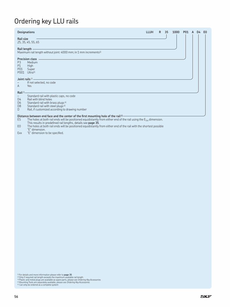
56
Designations
Rail size 25, 35, 45, 55, 65
Rail lengthMaximum rail length without joint: 4000 mm; in 1 mm increments1)
Precision classP3 MediumP1 HighP01 SuperP001 Ultra5)
Joint rails 2)
– If not selected, no codeA Yes
Rail 3)
– Standard rail with plastic caps, no codeD4 Rail with blind holesD6 Standard rail with brass plugs 4)
D8 Standard rail with steel plugs 4)
D Rail, if customized according to drawing number
Distance between end face and the center of the irst mounting hole of the rail 1)
ES The holes at both rail ends will be positioned equidistantly from either end of the rail using the EStd dimension. This results in predeined rail lengths, details see page 35.
E0 The holes at both rail ends will be positioned equidistantly from either end of the rail with the shortest possible “E” dimension.
Exx “E” dimension to be speciied.
1) For details and more information please refer to page 352) Only if required rail length exceeds the maximum available rail length3) Plastic and metal plugs are available as spare parts, please see Ordering Key Accessories4) Mounting Tools are separately available, please see Ordering Key Accessories5 ) Can only be ordered as a complete system
Ordering key LLU rails
LLUH R 35 1000 P01 A D4 E0

57
D
1) One size (M6) its for all carriage sizes and types, ordering designation LLUHZ VN.
Designations
Size 25, 35, 45, 55, 65
Additional sealing optionsS1 Scraper plateS3 Seal kit, additional front seal NBR with scraper plateS4 Additional front seal FKMS7 Additional front seal NBRS8 Seal kit, additional front seal FKM with scraper plate
Assembly tools for metal plugs25-45 D6 Assembly tool for sizes 25, 35 and 4545-65 D6 Assembly tool for sizes 45, 55 and 65
Caps and plugs as spare partsVP Set of 40 plastic capsTD6 Set of 40 brass plugsTD8 Set of 40 steel plugs
Grease nipples1)
25-65 VN-M6 Standard grease nipple, straight25-65 VN-M6-45 Grease nipple, 45 degrees25-65 VN-M6-90 Grease nipple, 90 degrees
Adaptors1)
25-65 VN UA Lubrication connector, extension M6 to M625-65 VN UB Reduction itting, from G1/8 to M625-65 VN UC Reduction itting, from M8x1 to M6
Quick lubrication couplings1)
25-65 VN SC Lubrication coupling, straight25-65 VN AC Adjustable coupling, 90 degrees
Adaptors for top lubrication (as spare part)VN TL1 for A, LA carriage, O-ring (size 25 - 55), O-ring + adaptor (size 65)VN TL2 for R, LR carriage, O-ring + adapter
LLUH Z 35 S1
Ordering key LLU accessories

58
® S
KF
is a
reg
iste
red tra
dem
ark
of t
he
SK
F G
rou
p |
© S
KF
Gro
up 2
017
| 1
5-0
68
0/1
LLU
Speciication sheet – Roller proile rail guide LLU
Please complete the form with all available information and send it to your SKF representative or authorized distributor for product selection.
SKF contact Date
General information
Customer ContactCompany Contact name
Address 1 Job title
Address 2 Department
Post code / Zip City State Phone (including country code) Mobile (including country code)
Country Mail
Project title
Reason for requestCurrent product / brand Description
○ Replacement ○ New design ○ Other
Application / Industry
○ Factory automation ○ Food and beverage ○ Machine tools Description
○ Medical ○ Semiconductor ○ Other
Export control and SKF policy (mandatory to mark)
○ The application is not subsidiary or part of industry of national defence and/or nuclear (also not with details of the function). The application is civil.
Commercial information
General
○ One shot business Quantity, pcs Batch size, pcs Start of supply, YYYY MM DD Target price / each Currency
○ Yearly repeating business
Application description

59
D
® S
KF is a registered
tradem
ark of the S
KF G
roup | ©
SK
F Grou
p 2
017 | 15
-06
80
/1 LLU
Stroke Rail length Center distance between or Short part dimensions Guiding systemcarriages, c rails, d Length Width Maximum height
mm mm mm mm mm mm mm
○ No constraints
Required service life distance or time (ill in all ields) Required static safety (in accordance to your business and application)Distance Total time Period of one cycle Stroke of one cycle
km h s mm
Maximum speed1) Maximum acceleration1) Rigidity of guiding system Running accuracy of guiding systemParallelism in height
m/s m/s2 N/µm µm
1) Here the maximum values. Enter load phase speciic values in table “External loads and load phases”
Parallelism in sideward direction
○ No speciic requirements µm
EnvironmentPresence of dust, dirt or luids Requirements on friction Preferred sealing version
○ Clean environment, e.g. laboratory ○ Lowest possible friction ○ Standard sealing
○ Standard industrial environment ○ Standard friction ○ Scraper plate (S1)
○ Dirty environment, e.g. milling machine ○ No requirement ○ Additional front seal NBR (S7)
○ Additional front seal FKM (S4)
○ Seal kit (S3)○ Seal kit (S8)
○ Humid or corrosive environmentIf yes, please describe:
Temperature [°C]Minimum Operating Maximum ○ Shock loads or vibrations
If yes, please describe:
Lubricant in use
Please specify (type, brand):
○ Grease (preferrably SKF LGEP2) ○ Oil lubrication
Sketch of the application (or attach a drawing)
Speciication sheet – Roller proile rail guide LLU

60
® S
KF
is a
reg
iste
red tra
dem
ark
of t
he
SK
F G
rou
p |
© S
KF
Gro
up 2
017
| 1
5-0
68
0/1
LLU
Product details
Product designation (if already known)
Carriage type
○ LLUHC-A ○ LLUHC-LA ○ LLUHC-R ○ LLUHC-LR
Rail type
○ LLUHR ○ LLUHR-D4 ○ LLUHR-D6 ○ LLUHC-D8
Preload class
○ T2 (8% C) ○ T3 (13% C)
Precision class
○ P3 (Medium) ○ P1 (High) ○ P01 (Super) ○ P001 (Ultra)
Needed accessories (for details see SKF publication 16404 Roller profile rail guide LLU)
○ Grease nipple straight (standard) (25-65 VN-M6)
○ Grease nipple 45° (25-65 VN-M6-45)
○ Grease nipple 90° (25-65 VN-M6-90)
○ Quick coupling straight (25-65 VN SC)
○ Quick coupling 90°, adjustable (25-65 VN AC)
○ Lubrication connector, extension M6 to M6 (25-65 VN UA)
○ Reduction itting, from G 1/8 to M6 (25-65 VN UB)
○ Reduction itting, from M8x1 to M6 (25-65 VN UC)
○ Assembly tools for metal plugs (LLUHZ … D6)
Speciication sheet – Roller proile rail guide LLU

61
D
® S
KF is a registered
tradem
ark of the S
KF G
roup | ©
SK
F Grou
p 2
017 | 15
-06
80
/1 LLU
Input for dimensioning calculation
○ No preference If yes, please describe:
○ Other
Moving direction (set coordinate system accordingly)Please specify:
○ Horizontal ○ Vertical ○ Other
External loads and load phases
Forces in N, Lever arms in mm measured from deined origin (see graphics above) If the application has more than 3 load phases, please copy this page.
Load phase 1 Load phase 2 Load phase 3
Stroke mm Stroke mm Stroke mm
Acceleration mm/s2 Acceleration mm/s2 Acceleration mm/s2
Speed m/s Speed m/s Speed m/s
Lever arms in Lever arms in Lever arms in
Force Fx x y z Force Fx x y z Force Fx x y z
Force Fy x y z Force Fy x y z Force Fy x y z
Force Fz x y z Force Fz x y z Force Fz x y z
Speciication sheet – Roller proile rail guide LLU
+Fy
+y
+Fz+z +F
x
+x
ORIGIN
+Fy
+y
+Fz+z
+Fx
+x
c
ORIGIN
1
2
+Fy
+y
d
+Fz+z
+Fx
+x
c
ORIGIN
1
4
3
2
+Fy
+y
d
+Fz+z
+Fx
+x
ORIGIN
1
2
○ Conig 24
○ Conig 12
○ Conig 22
○ Conig 11

62
Notes

63
Notes


