Amorphous alloys for brazing copper based alloys - IOPscience
Upload
trinhhuongCategory
view
213download
0
Paper No.
274
ROLES OF HzS IN THE BEHAVIOR OF ENGINEERING ALLOYS: A REVIEW OF LITERATURE AND EXPERIENCE
R.D. Kane and M.S. Cayard lnterCorr - CL1 International, Inc.
14503 Bammel-N. Houston, Suite 300 Houston, Texas 77014 USA
ABSTRACT
Hydrogen sulfide (H$) has long been associated with the cause of corrosion damage and sulfide stress cracking (SSC) in high strength steels and high hardness weldments used in oil and gas production, petroleum refining, and petrochemical/chemical processing. Other applications where sulfide species have produced environmental cracking include heavy water production, electric power, marine applications and many others where sulfate reducing bacteria can flourish and oftentimes produce substantial amounts of HZS. H$S has also been associated with internal blistering, hydrogen induced cracking (HIC) and stress oriented hydrogen induced cracking (SOHIC) of carbon steels used in refinery vessels in wet H2S service and pipelines containing sour (HzS-containing) fluids. In recent years, new stainless alloys have been implemented in lieu of conventional steels in many applications where H# corrosion is particularly severe. These materials have been used along with chemical inhibitors to mitigate corrosion. These alloys, however, may in some cases also be susceptible to SSC, localized corrosion and anodic stress corrosion cracking (SCC) in sour environments. In this review, the behavior of carbon and low-alloy steels, stainless steels, and nickel alloys in sour environments is discussed. Emphasis is placed on the identification of the various types of HzS-related corrosion and environmental cracking that can occur, the origin and mechanisms, and the methods of control.
Keywords: sulfide stress cracking, SSC, hydrogen induced cracking, HIC, stress oriented hydrogen induced cracking, SOHIC, steel, stainless steel, nickel base alloy
INTRODUCTION
For over five decades there has been a continual need to develop new materials technology for use in industrial applications involving exposure to H$S. Much of this effort has centered around the need for higher strength and more corrosion and/or embrittlement resistant materials that can withstand high temperature, high pressure, and increasing aggressive service environments. More recent research has
Copyright 01998 by NACE International. Requests for permission to publish this manuscript in any form, in part or I” whole must be made in wrItin to NACE International, Conferences Division, P.O. Box 218340, Houston, Texas 77218-8340. The mater@ presented and the VIEWS expressed in this paper are solely those of the author(s) and are not necessarily endorsed by the Association. Printed in the U.S.A.
been directed at identifying materials that can withstand service conditions where pressures and temperatures are in excess of 135 h4Pa and 200 C, in the presence of significant quantities of corrosive gases such as H$S and CO* and aggressive species such as chlorides and sult%r compoundst’l Of even greater importance is the need for more economic stainless steels with high strength and corrosion resistance to handle service applications involving exposure to high COr partial pressures in combination with low to moderate levels of HzS (1100 kPa). ~1
Additionally, downstream petroleum refining and petrochemical environments are subject to higher levels of corrosivity as a result of processing a greater variety of impure hydrocarbon feedstocks. Impurities such as H#, organic sulfide compounds, and nitrogen compounds, result in high levels of HzS, cyanide and ammonia which can also produce conditions for SSC and HIC of steels used in plant pressure vessels and piping. I31
Understanding of the role of H$S in the degradation of engineering has remained paramount over the past several decades in research. In addition to being extremely toxic, HrS is responsible for corrosion and environmental embrittlement in common materials of construction. Consequently, it has been necessary to develop special materials and processing methods that minimize the effects of corrosive degradation and maximize the integrity of these systems. Furthermore, through an understanding of H$- related cracking mechanisms, it has been possible to monitor and make adjustments to process environments to minimize H2S corrosion and embrittlement.
This paper reviews the roles of H# in the following corrosion phenomena:
1, Corrosion of steel 2. Sulfide stress cracking (SSC) 3. Hydrogen induced cracking (HIC) 4. Stress oriented hydrogen induced cracking (SOHIC) 5. Environmental cracking of stainless and Ni-base alloys
HYDROGEN SULFIDE CORROSION
Acidic Environments
HzS as well as CO2 can be dissolved in aqueous environments to form acidic, corrosive solutions (see Figure 1).t4’ From this behavior, these gases derive their commonly used name: acid gases. Depending on the temperature, pressure, and pH of the environment, aqueous environments containing H$ and/or COZ can be aggressive to carbon and low-alloy steels by causing severe weight-loss corrosion. Corrosion rates for low-alloy steels in acidic HrS-containing environments tend to increase with decreasing pH of the aqueous solutions. “1 Corrosion in these environments under anaerobic conditions commonly found in oilfield production typically occurs by the following processes: @’
anode: Fe+ Fe2’ +2e- (1)
cathode: H2S+HrO-+H++HS-+H20 (2) HS-+H20+H++SZ-+H20 (31
27412

net reaction:
Fe+H$ HzO+ FeS+2p (4)
Under acidic conditions, H$S is stable (See Figure 2) and can dissolve into the aqueous solution, t’] In practice 2 iron sulfide corrosion products are based on FeS as shown above but can take other molecular forms such as Fe&, Fe& or Fe& depending on the pH, H$ partial pressure and oxidizing potential of the environment.
Alkaline Environments
Many downstream hydrocarbon refining and petrochemical process environments operate at alkaline pH levels (>pH 7) by virtue of the chemical equilibrium established between dissolved H2S and ammonia in aqueous solutions. Corrosion processes tend to be different and more complex in these conditions versus those found in acidic environments. Typical corrosion reactions for iron in alkaline sour water environments are similar to those shown for acidic conditions in Equations 1-4.
For sulfide corrosion mechanisms which operate in the limited pH range common to many alkaline wet HzS processes (pH 7-lo), the active sulfide species are bisulfide (HS) and soluble sulfide (S’). As in acidic environments, sulfide corrosion products can be both stoichiometric and non-stoichiometric depending the conditions that prevail. In many cases, these sulfide films can impart protection from corrosion resulting in reduced corrosion rates. However, cyanide compounds can also be present in many cases and enter in the corrosion reaction according to the following equation:
FeS + 6CN + Fe(CN)e4- + S*- (5)
This reaction is significant because it results in a complex between iron and cyanide being formed and a destruction of the normally pseudo-passive sulfide films. It also results in the production of atomic hydrogen as shown below:
Fe + 2H’ + 6CNc4- -+ Fe(CN)e4* + 2I@ (6)
Production of Atomic Hydrogen
One of the natural byproducts of corrosion is the production of atomic hydrogen at local cathodic sites. Atomic hydrogen (tip) is readily adsorbed onto the metal surface. In most corrosive environments, the vast majority of this atomic hydrogen recombines on the metal surface to form hydrogen gas (Hz) which harmlessly bubbles off of the metal surface. However, in the presence of environments that contain sulfur species resulting from H2S (i.e. dissolved H$S, HS and S-*X the kinetics of recombination can be significantly retarded resulting in increased absorption of atomic hydrogen by the substrate material, This behavior results because sulfur is a highly effective hydrogen recombination “poison” which acts similarly to species such as Sn, Pb, Sb, P which increase the efficiency of hydrogen charging (a) defined by the following equation;
a. = H&IA (7)
where: HP = hydrogen produced by corrosion and HA = hydrogen absorbed into the material
27413

Under steady state conditions, in the absence of internal trapping of hydrogen, the efficiency of hydrogen charging can be represented as the simple ratio of the permeation current determined in a simple hydrogen permeation experiment’*’ and the corrosion current on the exposed surface. Additionally, the overall severity of hydrogen charging can usually be represented by the product of the corrosion current and the efkiency of hydrogen charging which is proportional to the hydrogen flux.
In most cases for sour environments, the hydrogen permeation flux versus time curve has the characteristic behavior shown in Figure 3. It increases and reaches a maximum value (.Jmax) and then the flux decreases to an intermediate steady state value (Jss) or slowly continues to decrease with time as semi-protective sulfide films form on the metal surface. However, if these films are disrupted due to chemical upsets in the service environment, flow induced shear stress or periodic surface inspection, another episode of high flux can ensue. From this figure, it can be seen that peak hydrogen flux may only be a passing situation. In some cases, chemical additions or inhibitors may be utilized to mitigate such transient situations; however, in others careful attention to metallurgical processing of the material must be utilized to prevent environmental cracking associated with these events,
As shown in the following sections, the absorbed hydrogen produced by exposure to H2S- containing environments can have a significant influence on the embrittlement and environmental cracking of materials, When evaluating the impact of hydrogen charging environments on materials, another meaningtid parameter is the subsurface hydrogen concentration (C,) on the surface exposed to an H2S environment. It is derived from the steady state hydrogen permeation current (JsB) and effective ditlksivity of hydrogen (Dee) in the material as shown below’*’
where L = metal thickness. This approach, shown schematically in Figure 4,tg1 allows for determination of critical values of hydrogen concentration (C*) for cracking of particular materials so that the role of metallurgical condition and processing can be understood and used to optimize service performance.
SULFIDE STRESS CRACKING OF STEELS
It is generally accepted that SSC is a form of hydrogen embrittlement cracking in most high strength steels. Admittedly, direct evidence to this effect is limited; but this is only due to the limited number of fimdamental mechanistic studies that have been conducted in sour environments. Sulfide stress cracking can be induced in susceptible materials by the simultaneous presence of tensile stresses and a corrosive environment containing a sufficient level of H$. The role of H2S in this phenomenon is generally considered to be two-fold: (1) it increases the rate of corrosion of steel in aqueous solutions, and (2) it poisons the hydrogen recombination/evolution reaction as discussed previously. Consequently, H$S results in increases in the severity of hydrogen charging versus similar environments without H2S.
Mechanisms of Sulfide Stress Cracking
From the above discussion, it would appear fortuitous that hydrogen is intimately connected with SSC failure. Most of the attributions of the role of hydrogen in SSC are based on similar cracking tendencies observed in SSC and hydrogen embrittlement tests on carbon and low-alloy steels in non-H2S containing environments. 11” However differences in SSC in Ni-containing, low-alloy steels have been observed which suggest that an anodic SCC mechanism is also possible in these materials.
27414
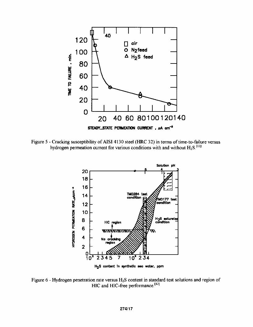
Hydrogen Embrittlement Cracking Mechanisms, A comprehensive mechanistic SSC study was conducted to identify specifically the mechanism of SSC in AISI 4130 steel which is the basis of most high strength steels used in oilfield service. tlil Tests were conducted both with and without H2S under conditions of applied potential to produce equivalent hydrogen permeation currents, As shown in Figure 5, susceptibility to SSC was found to be directly related to the amount of hydrogen available, not the presence or absence of H2S. In the case where the hydrogen-embrittlement mechanism prevails, hydrogen atoms f@) produced by corrosion or cathodic charging can recombine to form molecular hydrogen or can be adsorbed onto the metal surface and diffise into the metal. In an HZS-containing environment, the absorption of atomic hydrogen into the metal is enhanced by the poisoning effect of S-containing species indicated previously. This effect is shown in Figure 6, where the hydrogen charging characteristics of a low-ahoy steel in an aqueous medium are shown both as a timction of pH and HzS concentration, ‘l*] Once in the material, atomic hydrogen readily diffuses at ambient temperatures to sites of high internal stress (i.e. grain boundaries, inclusions, and regions of triaxial stress at notches). In the presence of tensile stresses, these locations become sites for embrittlement and the initiation of brittle cracking failure.
In recent years there have been substantial efforts for the transportation industry directed toward maximizing resistance to SSC in high strength steels used in oilfield casing and tubing and canisters used to contain pressurized natural gas. It appears that quenching and tempering (Q&T) is a preferred process for producing high strength steels with higher resistance to SSC than that obtained with other processing methods (e.g. annealing, normalizing and normalizing and tempering). Even more importantly, steels with a high percentage of transformation to martensite upon quenching exhibit maximum resistance to SSC following tempering (See Figure 7). ti3’ This effect has been associated with two major benefits of the Q&T process: (1) production of a martensitic structure in the material by balancing steel composition and the critical cooling rate to produce complete martensitic transformation, and (2) a fully martensitic, as- quenched structure allows tempering to be conducted at higher temperatures leading to production of a high SSC resistant spheroidized carbide structure while retaining high strength.
The use of AISI 4130 steels and its modifications with increased MO is particularly noteworthy since the C-Cr-Mo composition promotes both through-wall hardenability (i.e. martensitic transformation) and even higher tempering temperatures. This technology has been utilized to produce steels with up to 650 - 750 MPa yield strength with high resistance to SSC. Moreover, further innovations have been made to increase the SSC resistance of steels even farther. Studies show that grain refinement produced through a combination of thermo-mechanically controlled processing (TMCP), microalloying additions of Nb, Ti, V and B, and high tempering temperatures can increase the SSC resistance of steels in the range of 750 - 860 MPa yield strength. t14~151
Stress Corrosion Crackina Mechanisms. Ni-containing steels exhibit a different environmental cracking tendency to that of Ni-free steels as discussed previously. tL6’ Generally, steels with >l% Ni exhibit a greater susceptibility to environmental cracking in sour environments, (see Figure 8). However, some controversy still exists regarding this matter. More interesting still is the fact that these Ni- containing steels show a reduced tendency for environmental cracking with applied cathodic potentials. t”’ This is opposite to the effect expected if hydrogen embrittlement cracking mechanisms were operating, but indicative of the behavior that would persist if anodic SCC mechanisms were present.
SSC Fractography
In low-alloy steels, SSC appears as both transgranular and intergranular cracking. ‘is1 It is generally observed that SSC in high strength steels (>700 MPa yield strength) appears predominantly as
27415
intergranular cracking except where steels have been processed to maximize SSC resistance. Lower strength steels (~700 MPa yield strength) as well as high strength steels using enhanced processing to improve SSC resistance, have predominantly transgranular features. In low strength steels, the failure mode incorporates short blister cracks which are linked by transgranular cleavage cracks, This mechanism is more commonly described by the term stress oriented hydrogen induced cracking (SOHIC) and will be discussed in more detail in a later section of this paper. In the enhanced high strength steels, the transgranular mode is noted on the primary fracture surface with intergranular secondary cracks along prior austenite grain boundaries.
SSC - Environmental Variables
The three paramount environmental variables are solution pH, environment temperature, and H2S concentration.
pH and HIS Partial Pressure. In most environments, tendencies toward SSC of low-alloy steels generally decrease with increasing pH of the aqueous environment between pH 0 and 7. The reason for this behavior appears to be the decrease in availability of the hydrogen ion in aqueous media with increasing PH. It has also been commonly observed that SSC of low-alloy steels increases with increasing H2S concentration. Standard laboratory tests have been developed for SSC which evaluate materials in solutions adjusted to pH values in the range of 3 to 5 by varying H2S partial pressure and additions of acid and buffering agents such as bicarbonate or acetate. ‘lgZ *‘I Figure 9 shows the regimes of serviceability over this range for a typical API casing grade, low ahoy steel with a specified minimum yield strength of 760 MPa. It demonstrates the strong relationships among SSC, pH and HzS partial pressure. t”’
Temperature. Sulfide stress cracking is a highly temperature dependent phenomenon and has been used effectively in the design of some components that operate continuously at high temperatures in sour oil and gas applications (i.e. downhole tubing and casing). As shown in Figure 10, SSC susceptibility reaches a maximum at about room temperature and then decreases with increasing temperature over the range 25-200 C. t*”
HYDROGEN BLISTERING, HIC AND SOHIC
As previously discussed, one of the consequences of H2S corrosion is absorption of atomic hydrogen into the steel. Another manifestation of this behavior is the formation of internal blisters, HIC and SOHIC in susceptible steels. They are characterized by separations that generally run parallel to the surface of the material and are caused by the accumulation of molecular hydrogen. These separations may occur as large blisters or as a series of thin, blister cracks (referred to as hydrogen induced cracking - HIC) that step through the material. These parallel blister cracks may link up and propagate in a steplike manner until catastrophic failure occurs when the effective thickness of the material is sufficiently reduced.
One of the main distinctions between SSC discussed in the previous section and those cracking mechanisms involving hydrogen blistering indicated above is that SSC is a solid state embrittlement reaction resulting from the interaction between the metal lattice and the atomic hydrogen. On the contrary, blistering and HIC involves the recombination of atomic hydrogen to molecular hydrogen at weak internal interfaces (e.g. inclusions, and laminations) in the material. The blistering and HIC processes do not need the presence of externally applied tensile stress to occur. Under the influence of
27416

applied or residual tensile stress, however, the short blister cracks normally associated with HIC can form a stacked array in the through thickness direction. This phenomenon is referred to as stress oriented hydrogen induced cracking (SOHIC). When linked by short transgranular cleavage cracks, SOHIC can lead to failure by reducing the effective thickness. Blistering, HIC and SOHIC are generally observed in lower strength steels used in plate and pipe products with ~700 MPa yield strength.
Examples of SSC, HIC and SOHIC are shown in Figures 11 through 13, respectively.
Environmental Factors
The three paramount environmental factors in determining susceptibility of steels to blistering, HIC and SOHIC, are generally the same as those involved with SSC discussed previously in this paper - pH, H2S concentration and service temperature. This is not surprising since both types of phenomena are based on the materials response to absorbed hydrogen produced by the sulfide corrosion reaction, Susceptibility to cracking increases in acidic solutions with decreasing pH and increasing H2S concentration. However, the influence of service temperature differs between the hydrogen blistering- type cracking mechanism and SSC. Laboratory studies show that susceptibility to stepwise cracking increases with increasing temperature up to a maximum around 50 C and then decreases with tiuther increases in environment temperature (see Figure 14). (**I While the reasons for this behavior has not totally been confirmed, it is believed to be related to changes in hydrogen charging efficiency with temperature in aqueous, acidic solutions.
Since welded, low strength plate steels are more extensively utilized in downstream refinery applications, more extensive research has been conducted in alkaline (pH 7-10) sour water solutions found in these applications, As shown in Figures 15 through 17, t231 hydrogen flux increases with H2S, cyanide and chloride concentration and increasing service temperature. This is primarily due to the synergistic effects observed among these variables in increasing the hydrogen charging efficiencies to exceptionally high values when high levels of all variables are imposed, thus leading to severe conditions for HIC, SOHIC and SSC. In fact, one of the surprising aspects of these alkaline sour water environments is that, despite their high pH, hydrogen charging levels can be obtained that exceed those typically associated with severe acid solutions (i.e. TM0177 solution at pH 3).
Metallurgical Factors Influencing HIC and SOHIC
Susceptibility to HIC is highly dependent on the impurity content of the material, heat treatment and metallurgical processing. These variables influence the distribution of hydrogen in the material and the nature of the internal sites where hydrogen can recombine to form molecular hydrogen and accumulate. For example, susceptibility to HIC decreases with a reduction in the level of S in the steel (See Figure 18). 1241 A similar but lesser influence of P has also been identified. The predominance of the sulfur effect is related to the increase in number, size and aspect ratio of MnS inclusions with increasing S content. These inclusions act as primary sites for HIC at medium to high levels of sulfur in the steel. In some cases, Cu and Ca additions also appear to be beneficial in reducing HIC susceptibility. Cu additions greater than 0.2 wt percent reduce hydrogen absorption from sulfide corrosion in intermediate pH environments (4.8 - 5.2). t251 Ca additions help improve I-IIC resistance through sulfide inclusion shape control by breaking up the normally elongated inclusions to a more spherical shape (i.e. reduce the inclusion aspect ratio). This shape is less conducive to the initiation of the planar blisters typical of HIC. ‘261 However when S contents are very low, over-treatment by Ca can increase susceptibility to MC by the formation of Ca containing inclusions (See Figure 19).
27417
Resistance to HIC can also change with the metallurgical processing method used in steel production. Highest susceptibility is associated with hot rolled structures. Normalizing, quenching and tempering have been shown to increase HIC resistance (See Figure 18) particularly at lower S content. Thermo-mechanically controlled processing (TMCP) of pipe and plate steels, combined with lower S levels and carbon equivalents has resulted in a high resistance to HIC. This effect is considered to be the result of a reduction of the microstructural (ferrite/pearhte) banding in the material with normalizing and quenching and tempering processing methods. The carbide-rich bands are considered secondary sites that can predominate once sulfur levels are reduced.
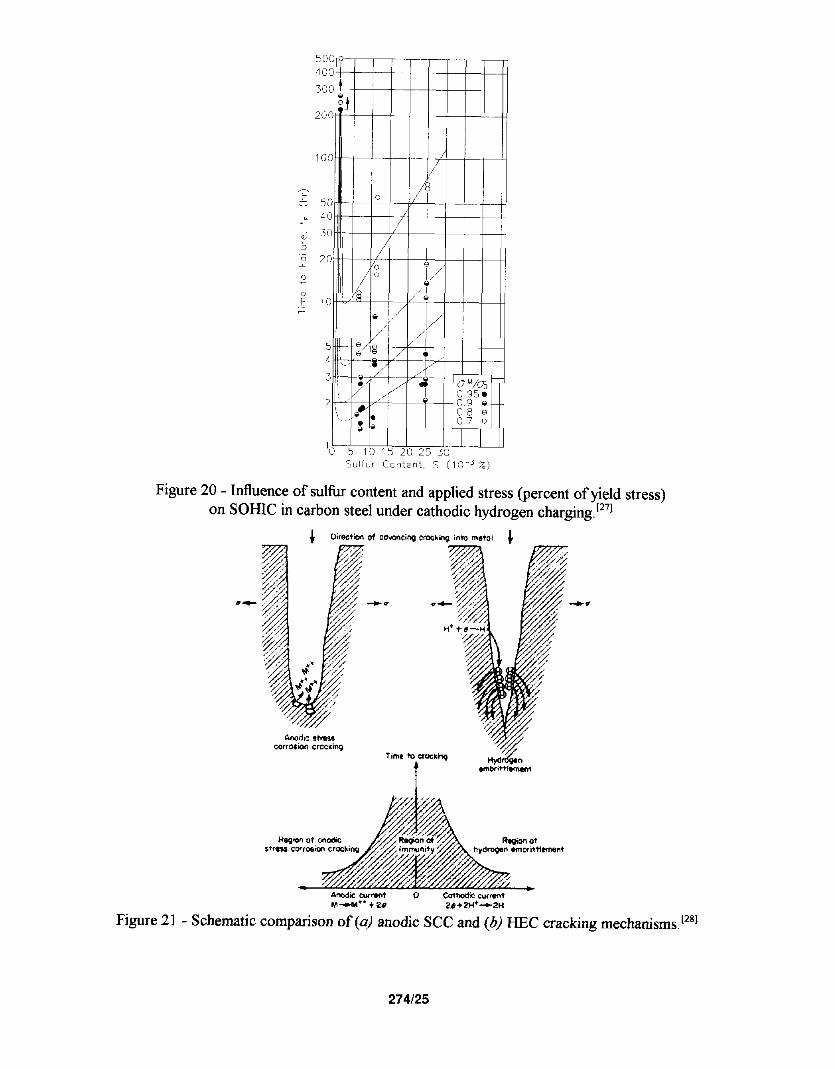
One very important aspect of susceptibility to SOHIC does not follow all of the same relationships commonly observed for I-IX. Maximum susceptibility to SOHIC is associated with low to intermediate sulfur levels (0.002 to 0.010 wt. percent S). As the susceptibility to HIC decreases with decreased S content of the steel, the tendency to form through thickness arrays of blister cracks (i.e. SOHIC) under applied tensile stress increases with reduced sulfur content until ultra-low sulfur levels (iO.001 wt. percent S) are reached (See Figure 20). t271 In most cases, attention to design and post weld heat treatment can be utilized to reduce operating stresses in welded equipment to levels below those required to produce SOHIC. However, in some cases, the combined effects of low to intermediate sultur levels and microstructural banding can combine to result in SOHIC at stress levels around ASME allowables. Therefore, caret%1 attention to metallurgical processing and materials qualification are required to assure resistance to SOI-IIC.
ENVIRONMENTAL CRACKING OF HIGH-ALLOY MATERIALS
Stainless steels and Ni-base alloys offer great potential in engineering design by eliminating the dependence on corrosion inhibitors. However, it must be realized that these materials can, in some cases, act very differently than steels and are subject to a different set of engineering limitations. In addition, in order to justify corrosion resistance alloys (CRAs) for many applications, they must also have high strength. In addition, these materials must be able to overcome the detrimental effects of H& CO2 gas, sulfur compounds, and concentrated brine solutions. To obtain high strength and corrosion resistance, there has been increased use of materials containing high levels of chromium, nickel, and molybdenum (Table 1).
Two important areas of concern for CRAs are that their corrosion and cracking behavior is generally more complex than that observed for conventional steels. For example, some stainless and nickel alloys may be susceptible to cracking by either a hydrogen-embrittlement-cracking (HEC) process or by anodic SCC in chloride-containing aqueous environments, or by both mechanisms. The mechanisms involved in hydrogen-related HEC and anodic SCC processes are contrasted in Figure 2 1. [*‘l
To understand the behavior of high-alloy materials in oilfield production environments, four classifications of materials need to be made. They are (1) martensitic stainless steels, (2) duplex stainless steels, (3) high-ahoy austenitic stainless steels, and (4) Ni-base alloys. Typically, conventional austenitic stainless (AISI 3XX series) steels do not have adequate strength or resistance from SCC for use in most H2S applications. Each classification has different ranges of composition, microstructure, strengthening mechanism, and performance in corrosive production environments. As a rule, CRAs do not behave as one class of materials.
27418

Martensitic Stainless Steels
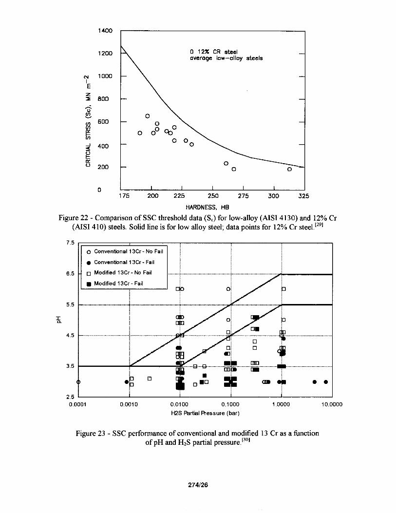
Martensitic stainless steels have been used in oilfield production for many years. These have been nominally 12%Cr stainless steels based on wrought AISI 4 10 or cast CA15 stainless steels. AISI 410 and similar alloys have been found to be more susceptible to SSC in severe H2S environments than low-ahoy steels .at corresponding strength levels (see Figure 22). t*‘l However when used within their limiting conditions of pH and H2S partial pressure, they can provide exceptioni serviceability.
Recently, new grades of martensitic stainless steels with improved mechanical properties have been introduced. For example, high-strength tubular grades of martensitic stainless steels with yield strengths up to 760 MPa have been developed for oilfield tubulars. They are nominally 13%Cr stainless steels and are used in the quenched and tempered condition. Newer materials also contain additions of 4 to 6 percent Ni and 1.5 to 2 percent MO for added resistance to localized corrosion superior to the straight 13Cr alloys. They also show better SSC resistance than the more commonly used AISI 410 steels and 13Cr steels (See Figure 23). 13” As indicated for SSC (and also true for high temperature corrosion resistance), performance is highly dependent on pH leading to a major increase in performance above pH4.
Maximum susceptibility to cracking in martensitic stainless steels typically occurs near room temperature with decreasing cracking susceptibility with increasing service temperature. This is consistent with the mechanisms of SSC in carbon and low ahoy steels. Resistance to environmental cracking is dependent on pH, H2S partial pressure and chloride concentration in the environment. Resistance to cracking is dependent on the material remaining essentially passive. Once the environmental severity increases beyond certain limits (which are characteristically different for each material composition and material condition), passivity is lost and sulfide corrosion commences. This corrosion is usually of a localized nature which can generate atomic hydrogen at sufficient levels to produce SSC.
Duplex Stainless Steels
Duplex stainless steels are a mixture of two microstructural constituents, ferrite and austenite. They can be produced in both cast and wrought conditions and typically have 22 to 25 percent Cr with yield strengths of 350-620 MPa when in the cast or annealed conditions. These steels derive their mechanical properties and microstructure from a balanced chemical composition which contains alloying additions of chromium, nickel, molybdenum and nitrogen. This results in a material with a corrosion resistance generally superior to those of the martensitic stainless steels in HzS, CO*, and brine environments together with a material strength, which is greater than conventional austenitic stainless steels.
Wrought duplex stainless steels have been introduced with strength capabilities between 400 and 900 MF’a yield strength. Unlike low-ahoy steels and martensitic stainless steels, duplex stainless steels can be strengthened by cold working during processing to reach maximum conditions. While this cold working has a generally negative effect on susceptibility to environmental cracking, the effect appears to be of secondary importance in most cases when it is limited to no more than about 30 percent cold reduction in tubular materials.
Laboratory tests indicate that these materials can be susceptible to cracking in environments containing HzS and brine. The studies also indicate that the cracking behavior of these materials is somewhat different from that observed for low-ahoy steels. Duplex stainless steels tend to be susceptible
27419

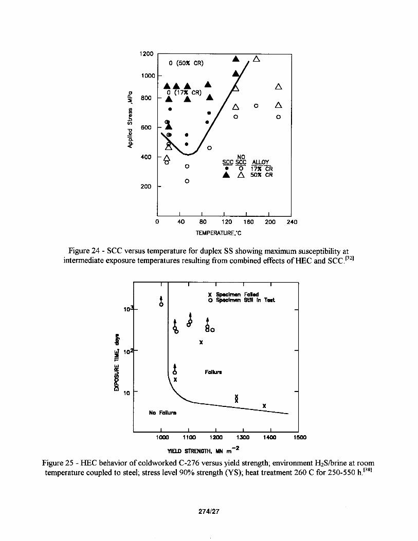
to environmental cracking at both low and high temperatures whereas SSC of high-strength steels and martensitic stainless steels tends to be a low-temperature, hydrogen-related phenomenon. The cracking of duplex stainless steels in brine solutions with H2S and CO2 results from environmental cracking of the ferrite phase by HEC at low temperatures, and by anodic SCC at high temperature. 13’] This results in a maximum susceptibility to environmental cracking at intermediate temperatures generally found in the range 60 to 120 C depending on the specific ahoy and test method utilized for evaluation (See Figure 24). [321 The maximum allowable H2S content for crack-free behavior with duplex stainless steels appears to be only slightly higher than that observed for more corrosion resistant martensitic stainless steels (e.g. 13Cr-5Ni-2Mo steels). However, as with the martensitic stainless steels, serviceability is still very dependent on pH with pH 4 being a major dividing line in performance. Research on the 22-25% Cr duplex stainless steels indicates that this limiting level of H2S is between 0.7 and 35 kPa partial pressure H2S. ‘331 Due to the increased cost of duplex stainless steels, their main advantage appears to be their higher strength capabilities when coldworked.
Austenitic Stainless Steels
High-ahoy austenitic stainless steels are being introduced into H2S service applications primarily for use as high-strength tubular materials. These materials have a fully austenitic microstructure with high levels of Ni, Cr, MO and N. This austenitic structure is stable even after high levels of cold working during processing. Highly alloyed austenitic stainless steels in tubular form can be cold worked in the range of 30 to 50 percent cold reduction to strength levels in tubular material between 750 and 1,000 MPa yield strength.
High-ahoy austenitic stainless steels have exceptionally good corrosion resistance. In an H2S and chloride containing environment, high levels of Cr and MO offer these materials resistance to both general and localized corrosive attack. Alloying additions of N also benefit by increasing pitting resistance. However, it appears that the benefit of N in high ahoy austenitic stainless steels exposed to H2S- containing environments is not as great as observed in non-sulfide containing, oxidizing, chloride- containing environments (e.g. aerated seawater).
There are many materials that fall into this ahoy classification which have varying concentrations of Cr, MO and N. Their corrosion behavior can vary substantially depending on actual composition. Generally, these are correlated based on pitting resistance equivalent number (PREN) given by the following equationt341:
PREN=Cr+3,3Mo+ llN+ 1.5(W+Cb) (9)
where the constant associated with N is 11 which is lower than 30 commonly utilized in non-sulfide containing oxidizing environments (recalling the above discussion). t351 Additionally, benefit is also assigned to alloying additions of W and Cb. Nickel also appears to have benefit in these materials even though it does not appear in the pitting resistance as indicated in Equation 9.t361 This most likely results from an increase in general corrosion resistance associated with the substitution of nickel for iron which delays the onset of localized corrosion and SCC to higher temperatures and more aggressive environments (See section on Ni-Base Alloys).
Laboratory tests on these materials indicate they are very resistant to HEC at low temperatures. However, they can be susceptible to cracking in severe, high-temperature brine environments by an anodic cracking mechanism similar to that of chloride SCC of AISI 304 and 316 stainless steels.
274/l 0
Hydrogen sulfide and other sulfur compounds appear to accelerate anodic SCC in much the same way that oxidizing agents increase the severity of SCC in non-sulfide containing environments. Susceptibility to SCC increases with the strength level and level of cold work of the material. Laboratory tests also indicate that the limiting conditions of H2S for these materials may be on the order of 70-700 kPa partial pressure H2S, at temperatures up to 220 C. t3”
Ni-Base Alloys
Two groups of Ni-base alloys are being employed in equipment primarily for use in service environments containing high H2.S partial pressures. Both offer extremely high resistance to SSC and corrosion by virtue of their ahoy composition that contains high levels of Ni, Cr and MO. These materials typically have between 5 and 20% iron. The distinction between the two groups of Ni-base alloys is made on the basis of how the high-strengthening is obtained. For tubular goods, Ni-base alloys can be cold worked to strength levels in excess of 1,000 MPa yield strength. For other components, such as valves and specialized equipment which often require more complex shapes or welding, precipitation hardened Ni-base alloys, which obtain their strength via aging heat treatments, are available with nearly the same strength levels.
High-strength Ni-base alloys exhibit environmental cracking in H2S and brine environments at temperatures ranging from 25 C to higher than 220 C. ‘37*3*1 At low temperatures, Ni-base alloys with less than 5 percent Fe can exhibit I-EC. Failures result from cathodic (hydrogen) charging of Ni-base alloys in environments containing aqueous HzS accelerated by galvanic contact with steel or other less noble alloys. The amount of hydrogen charging produced by the Ni alloy/steel galvanic couple in aqueous HZ!3 environments is sufficient, in many cases, to produce I-EC in a susceptible material. However, the material conditions where HEC is observed is limited to hardnesses in excess of HRC 40 produced by cold working and/or heat treatment and may vary with ahoy composition and microstructure. Maximum susceptibility to cracking occurs as a result of low temperature heat treatments or prolonged high temperature service exposures (between 250 and 550 C) in combination with transverse stresses relative to the cold working direction used in metallurgical processing. Similarly to SSC in steels, HEC in Ni-base alloys is less severe at elevated temperatures, see Figure 25. t3*] The current use of these materials is based on the control of strength and hardness levels, eliminating low-temperature heat treatment, and control of the environment by minimizing galvanic interactions,
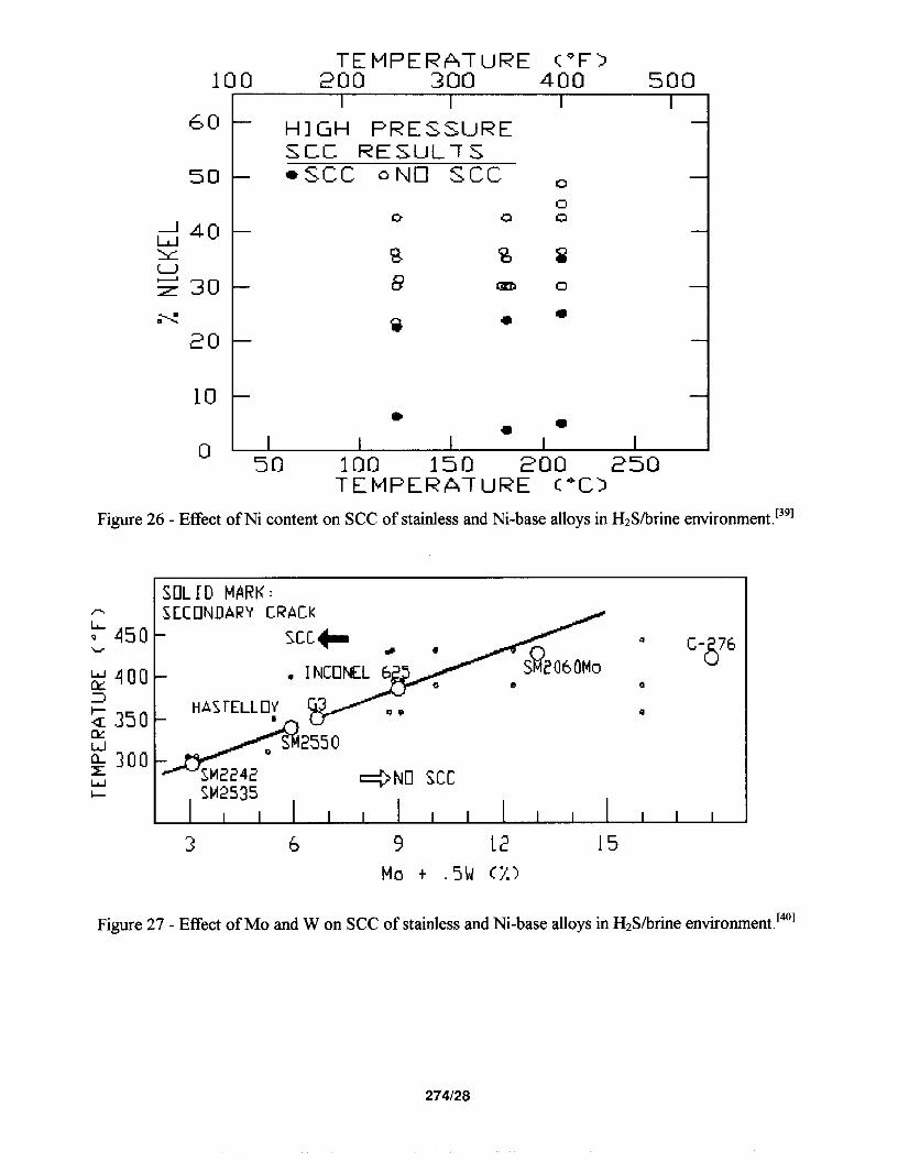
Nickel-base alloys can also exhibit SCC at temperatures greater than 150 C. [373381 This phenomenon is essentially the same as that observed for austenitic stainless steel in high-temperature chloride-containing environments (see Figure 21). But, it is generally limited to only very severe corrosive conditions for these alloys, often those that contain very high levels of H2S in combination with near saturated brine solutions and sometimes the presence of elemental sulfur. Resistance to cracking is related to ahoy composition based on the PRE values as indicated previously. Benefits in terms of SCC resistance are obtained with increased Ni, MO and W content as shown in Figures 26 and 27. t39, 401
SUMMARY
H2S is associated with corrosion damage and contributes to several forms of environmental embrittlement. These forms of embrittlement include internal hydrogen blistering, HIC and SOHIC of carbon steel plate and pipe material and SSC in high strength steels or hard weld zones. It can also contribute to SSC, I-EC, localized corrosion and anodic SCC stainless and N&base alloys. In many cases, these phenomena are controlled by similar environmental and metallurgical parameters (e.g. pH,
274111
temperature, H2S partial pressure, material composition, metallurgical processing and microstructure). However, the influence of these parameters may vary depending on the specific material and phenomenon in question. Consequently, they need to be considered separately for accurate prediction and assessment.
REFERENCES
1. R.N. Tuttle: Mater. Perform., Vol. 12, Feb. 1974, pp 42-45 2. M.B. Kermani, G. Weighill, T. Pendlingtom and G. Elliot, Corrosion/95, Paper No. 96, NACE
International, March 1995. 3. R.D. Merrick, Wet H&Y Cracking of Carbon Steels and Weldments, ed. R.D. Kane, R.J. Horvath,
M.C. Cayard, NACE International, 1996, p 145. 4. M. Bonis and J.L. Crolet, Corrosion Science, Vol. 27, No. 10/l 1, pp 1059-1070, 1987. 5. S. Srinivasan and R.D. Kane, Corrosion/96, Paper No. 11, NACE International, March 1996. 6. B.R. D. Gerus: Proc. Symp. On Sour gas and crude, Paper 5 188, SPE-AIME, Nov. 1974. 7. D. Abayarathna and R.D. Kane, Corrosion/96, Paper No. 606, NACE International, March 1996. 8. G148, Stanctard Practice for Evaluation of Hydrogen Uptake, Permeation and Transport in Metals
by an Electrochemical Technique, Annual Book of Standards, Vol. 3.02, ASTM, Wet Conshohoken, PA, to be published 1998.
9. M.S. Cayard, R.D. Kane, Corrosioti95, Paper No. 329,NACE International, March 1995. 10. D. Warren and G. W. Beckman: Corrosion, 1957, Vol 13, No. 10, pp 631-646. 11. B. J. Berkowitz and F. H. Henbaum: Corrosion, Vol. 40, No. 5, 1984, pp 240-245. 12. Y. Nakai, H. Ku&a&i, N. Totsuka, and Y. Wesuhg: Corrosion 82, Paper No. 132, NACE
International, March 1982. 13. M. Watkins and R. Ayer, Corrosion/95, Paper No. 50, NACE International, March 1995. 14. T. Kaneko, etal., Corrosion, Vol. 45, No. 1, 1989, pp 2-6. 15. Y. Ku&i, et. al., Corrosion/94, Paper No. 74, NACE International, March 1994. 16. R. S. Treseder and T.M. Swanson: Corrosion, Vol. 24, No. 2, 1968, pp 31-37. 17. A.K. Dunlop: Corrosion, Vol. 33, No. 3, 1978, pp 88-96. 18. M. Watkins, M. F. Bluem, and J. B. Greer: Corrosion, Vol. 32, No. 3, 1976, pp 102-109. 19. TM0 177, Laboratory Testing of Metals for Resistance to Specific Forms of Environmental Cracking
in HzS Environments, NACE International, 1996. 20. EFC Publication 16, Guidelines on Materials Requirements for Carbon and Low Alloy Steels for
HzS-containing Environments in Oil and Gas Production, The Inst. of Metals, ISSN 1354-5116, 1995.
2 1. H.E. Townsend, Jr: Corrosion, Vol. 28, No. 1, 1972, pp 39-45. 22. G.J. Biefer, Wet HZS Cracking of Carbon Steels and Weldments, ed. R.D. Kane, R.J. Horvath, M.C.
Cayard, NACE International, 1996, p 483. 23. R.D. Kane, D. Abayarathna, Proc. 2”d International Co@ On Interaction of Steels with Hydrogen in
Petroleum Industry Pressure Vessel and Pipeline Service, ed. M. Prager, The Materials Properties Council, Inc., New York, 1994, pp 195-206.
24. R.D. Kane and S. Srinivasan, Serviceability of Petroleum, Process and Power Equipment, Ed. D. Bagnoli, M. Prager and D.M. Schlader, ASME, PVP Vol. 239MPC Vol. 33, 1992, p 170.
25. H. Inagaki, et. al., Trans. ISIJ, Vol. 18, 1978, p. 149. 26. T. Taira, Wet HzS Cracking of Carbon Steels and Weldments, ed. R.D. Kane, R.J. Horvath, M.C.
Cayard, NACE International, 1996, p 5 12 27. M. Iino, Wet H2S Cracking of Carbon Steels and Weldments, ed. R.D. Kane, R.J. Horvath, M.C.
Cayard, NACE International, 1996, pp 47 l-478 28. M. Fontana, Corrosion Engineering, McGraw Hill, New York, 1986, 148.
274112

29. R.S. Treseder and T.M. Swanson, Corrosion, Vol. 24, No. 2, 1968, pp 31-27. 30. M.S. Cayard and R.D. Kane, Proc. Eurocorr’97, The European Corrosion Congress, EFC, Event
208, Trondheim Norway, Sept. 1997, pp 109-l 15. 3 1. S.M. Wilhelm and R.D. Kane, Corrosion Resistant Alloys in Oil and Gas Production, ed. J. Kolts
and S.W. Ciraldi, NACE International, 1996, pp 621-629. 32. P.R. Rhodes, G. Welch and L. Abrego, Corrosion Resistant Alloys in Oil and Gas Production, ed. J.
Kolts and SW. Ciraldi, NACE International, 1996, p 539. 33. Y. Ishizawa, et. al., Corrosion/83, Paper No. 167, NACE International, March 1983. 34. S. Srinivasan and R.D. Kane, Corrosion/92, Paper No. 56, NACE International, March 1992. 35. J. Oredsson and S. Brernhardsson: Corrosion 82, Paper No. 126, NACE International, March 1982. 36. E.L. Hibner, C.S. Tassen and J.W. Skogsberg, Proc. Eurocorr’97, The European Corrosion
Congress, EFC, Event 208, Trondheim Norway, Sept. 1997, pp 73-78. 37. R.D. Kane et al.: Corrosion/79, Paper No. 174, NACE International, March 1979. 38. G. A. Vaughn and J. B. Greer: SPE-AIME Annual Meeting, Sept. 1980, Dallas, Texas, Paper 9240. 39. S. Ciraldi, Corrosion/87, Paper No. 284, NACE International, March 1987. 40. Ikeda, et. al., Corrosion Resistant Alloys in Oil and Gas Production, ed. J. Kolts and S.W. Ciraldi,
NACE International, 1996, p 803.
274113

TABLE 1 STAINLESS STEELS AND NICKEL-BASE ALLOYS COMPARISON
Stainless Steels
Nominal compositions, wt%
Designation Fe Ni Cr MO N Other Comments
MarYensiffc SS 130 Bal - 13 - - - low cost/resists CO2 corrosion
Modified 13Cr* Bal 5.0 13 2.0 - - improved corrosion resistance (esp. in H$3) and strength over 13Cr
15Cr Bal 1.5 14.5 0.5 - - improved corrosion resistance over 13Cr
Duplex SS 18CF Bal 4.5 18.5 2.5 00.7 - lower cost than 22/25Cr alloy 22Cr Bal 5.5 22.0 3.0 0.10 - resists CO2 and low/mod HzS 25Cr Bal 8.0 25.0 3.5 0.20 w higher corrosion and SCC resistance
than 22Cr esp w/added MO and W High alloy austenitic SS
Alloy 28 Bal 31 .o 27.0 3.5 - - higher resistance to CO*, mod H2S and cl-
Alloy 254* Bal 18.0 20.0 6.0 0.20 - low Ni and Cr content but high MO and N for pitting resistance
Alloy 904* Bal 25.0 21.0 4.5 - - low Ni and Cr content but high MO and N for pitting resistance
Alloy 6XN* Bal 24.0 21.0 6.5 0.20 - low Ni and Cr content but high MO and N for pitting resistance
Nickel-Base Alloys
Nominal composition, wWo/o
Designation Fe Ni Cr M N Other Comments 0
Cold worked
2535* Bal 38.0 25.0 3.0 - - lower nickel content than 825, higher, higher pitting resistance
825 Sal 42.0 21.0 3.0 - - good resistance to COz/high H2S and Cl/moderate temperature
G-30* 20 Bal 22.0 7.0 - - good resistance to C02/high H2S and Cl-/high temperature
2550* 20 50.0 25.0 6.0 - 2.5W better resistance than G3 to COzlhigh HzS and Cl-
G-50 17 50.0 20.0 9.0 - - better resistance than G3 to COzlhigh H2S and Cl-
c-22* 4.0 Bal 21.0 13. - 3.OW alternative to C-276 in some environments 5
C-276 5.5 Bal 15.0 16. - 3.5W excellent resistance to COz/high HzS and Cl-/very high 0 temperature and sulfur
PrecipBatbn hardened 925* Bal 42.0 21.0 3.0 - 2.OTi lower Ni and cost option to alloy 718
718 Bal 52.0 19.0 3.0 - 1 .OTi/ good resistance to C021mod H2S and Cl- 5.OCb
725* 8.0 Bal 21.0 8.0 - 3.4 better pitting and SCC resistance than 718
625 plus* 5.0 Bal 21.0 8.0 - 1.5Til better pitting and SCC resistance than 718 3.5Cb
* New alternative alloys
274/l 4

Figure 1 - Relationship of pH to acid gas partial pressure in acidic systems.[4’
3 4 5 6 7 6 9 10 1112131415 PH
Figure 2 - Relative concentration of sulfide species versus PH.[~’
274115

Figure 3 - Typical hydrogen flux time curves for steels exposed to H$-containing environments
Test duration (h3
I.D. Through-wall crack penetration (X) o.
0 20 40 60 60 1 I
I Nd crpcking
CS - Conventional Steel HRS - ‘HIC Resistant” Steel
TMCP - Thermo-mechanicolly Contmlled Proceased Steel
c/ met;C , , ‘\
D 0.1 0.2 0.3 0.4 t Depth from I.D. (inches)
Figure 4 -Hydrogen concentration vs. thickness for one-side vessel exposure to TM0177 solution. Shows schematically critical hydrogen concentrations for HIC of various steels and SSC in weld metal.[”
274116
120
i 100
E.
i
80
60
i 4o
20
0 20 40 60 80100120140
Figure 5 - Cracking susceptibility of AISI 4130 steel (HRC 32) in terms of time-to-failure versus hydrogen permeation current for various conditions with and without HZS,t”l
18 -
T 16 -
4 14-
p 12-
f 'O-
il 8- b 6-
I 4 - - 2
45 7 1Oa 234
HlC mglon h
NC
H2S c~ntant In ythatlc wa water. ppm
Figure 6 - Hydrogen penetration rate versus HzS content in standard test solutions and region of HIC and HE-free performance.‘121
274117

i
40 60 80 100
Martensite at Center (% )
7 - Threshold stress for SSC versus percent as-quenched martensite for AISI 4130 Mod steels in the yield strength range 620 - 720 MPa.‘131
20 jb -
16
:
A 10 ~%NI A. / 0 0.8%Ni
A 0 >I O%Ni
A 1
0
I I I I I I I 180 220 260 300 340 380
HARDNESS, BHI\I
Figure 8 - Effect of Ni content on cracking susceptibility of a low-alloy (C-Cr-Mo) steel. Note reduced S, values for steels with more than 1 percent Ni at less than BHN 240.[16’
274118

7.5
6.5
5.5
I Q
4.5
3.5
2.5 I I r r
0.0001 0.0010 0.0100 0.1000 1 .oooo 10.0000
H,S Partial Pressure (bar)
Figure 9 - SSC serviceability regimes based on pH and H$ partial pressure.‘2”1
-c, I I
0 50 100
TEMPERATURE;C
Figure 10 - Effect of pH value on sulfide stress cracking resistance of an API casing steel (C-Mn composition).[211
274119
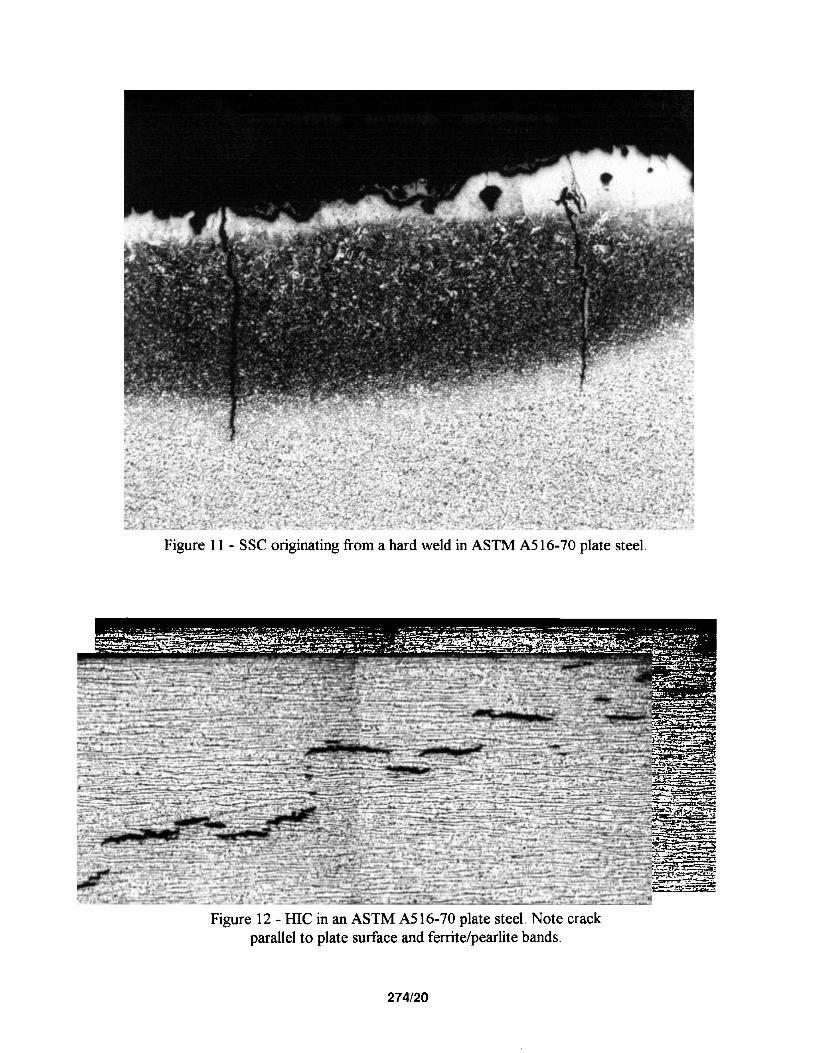
Figure 11 - SSC originating from a hard weld in ASTM A516-70 plate steel.
Figure 12 - HIC in an ASTM A516-70 plate steel. Note crack parallel to plate surface and ferritejpearlite bands.
274120

Figure 13 - SOHIC in the base metal adjacent to a weld heat 2 on an ASTM A5 16-70 plate steel.
lffected zone
274121
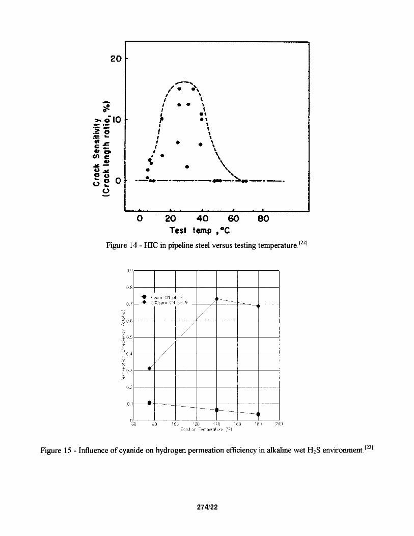
Figure 14 - HIC in pipeline steel versus testing temperature.‘221
0 20 40 60 80 Test temp .+YJ
100 100 120 120 140 140 160 160 180 230 230 Sal",lan Temperaf"re rij Sal",lan Temperaf"re rij
Figure 15 - Influence of cyanide on hydrogen permeation efficiency in alkaline wet Hz!3 environment .1231

Figure 16 - Influence of pH on hydrogen permeation efficiency in alkaline wet H$ environment.[231
01' d k/,
I I I
oc ~ -----/ 0 1000 2000 3000 41
Sulfide Cnncentr"+,on (ppm)
Figure 17 - Influence of chloride on hydrogen permeation efficiency in alkaline wet Hz.9 environment.1231
274123
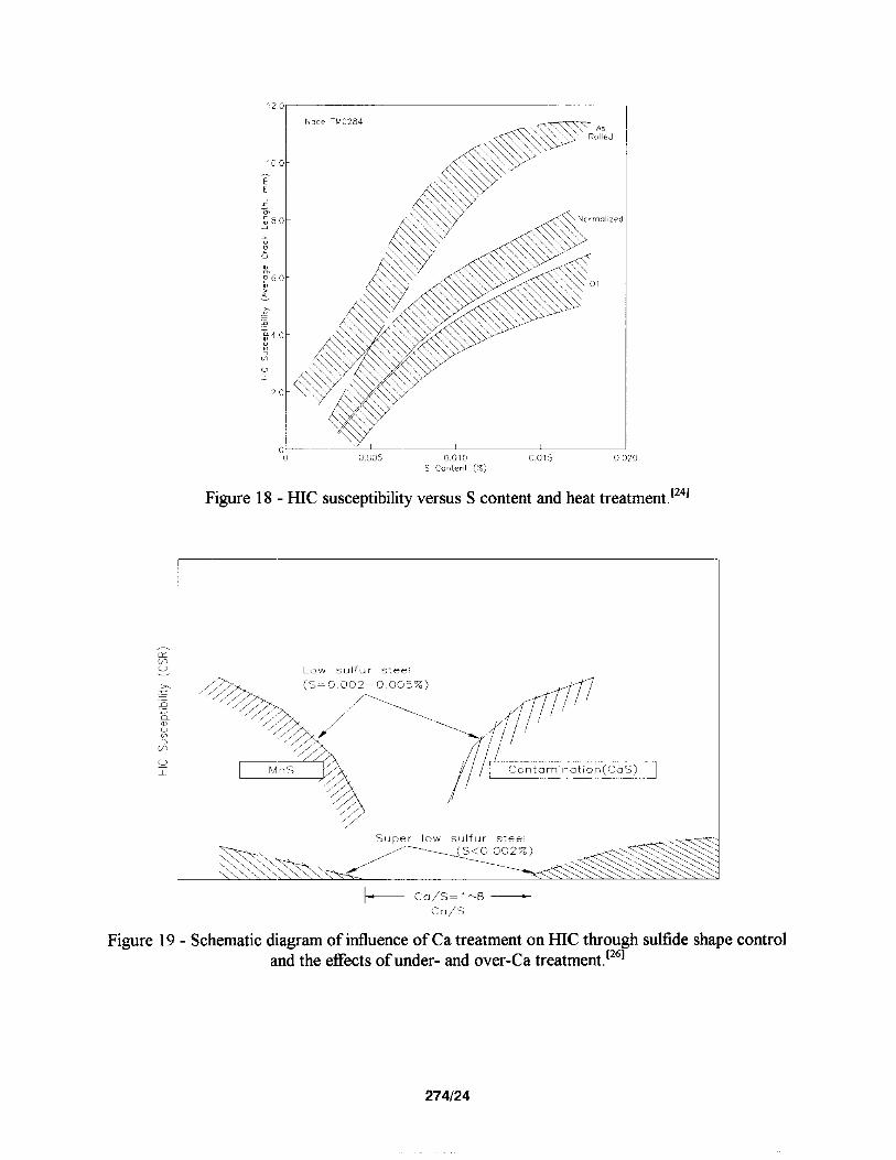
Figure 18 - HIC susceptibility versus S content and heat treatment.‘241
Figure 19 - Schematic diagram of influence of Ca treatment on HIC through sulfide shape control and the effects of under- and over-Ca treatment.r261
274124
,LJ_III 0 5 10 15 20 25 30
Sulfur ccntrnt. s (10-3 %)
Figure 20 - Influence of sulfix content and applied stress (percent of yield stress) on SOHC in carbon steel under cathodic hydrogen charging.[271
Figure 21 - Schematic comparison of (a) anodic SCC and (b) HEC cracking mechanisms.[2’
274125
1400
1200
T 1000
E
g 800
A ::
- fi 600
R
2 400
E 0 200
0
0 12% CR steel average low-alloy steels
175 200 225 250 275 300 325
HARDNESS, HB
Figure 22 - Comparison of SSC threshold data (S,) for low-alloy (AISI 4130) and 12% Cr (AISI 410) steels. Solid line is for low alloy steel; data points for 12% Cr steel.‘2g1
. Conventional 130 - Fail
q Modified 130 - No Fail
0.0100 0.1000
MS i+tiil Ressure (bar)
Figure 23 - SSC performance of conventional and modified 13 Cr as a function of pH and H2S partial pressure.‘301
274126
50% CR 0
200 -
I I I I I
0 40 80 120 160 200 240
TEMPERATURE,'C
Figure 24 - SCC versus temperature for duplex SS showing maximum susceptibility at intermediate exposure temperatures resulting from combined effects of HJZC and SCC.t3*’
No Failum
I I I I I
lam 1100 IZCUY 1300 1400
WELO STRENGTH, MN m-2
I I I I
X !Spaalmon Failed 0 Spaolman Still In Teat
151 Do
Figure 25 - HEC behavior of coldworked C-276 versus yield strength; environment H&brine at room temperature coupled to steel; stress level 90% strength (YS); heat treatment 260 C for 250-550 h.t3’]
274127
TEMPERATURE c-F> 100 200 3cm 400 500
I I I I 60 - HIGH PRESSURE
S-CL RESULTS 50 - -SCC oNEI SCC o
0
d 0 0 0
40 - Lxc 8 8 8 v 5 30 - 8 ml 0
c---F u + l
20 -
10 - e
m l
cl I I I I I
50 100 150 200 250 TEMPERATURE C”C3
Figure 26 - Effect of Ni content on SCC of stainless and Ni-base alloys in H&brine environment.[391
1 SOL ID MCIRK : SCCCNIARY CRACK c
3 6 9 12 15
MO t .5W C%,
LI c ,- 76 a
Figure 27 - Effect of Mo and W on SCC of stainless and Ni-base alloys in H2Sibrine environment.[401
274128


![CENTERITY SERVICE PACK FOR CLOUDERA€¦ · OOZIE [roles status] • CLOUDERA ROLES SOLR [roles status] • CLOUDERA ROLES SPARK [roles status] • CLOUDERA ROLES SQOOP [roles status]](https://static.fdocuments.in/doc/165x107/5fc0df6d43307a59a12ae0a7/centerity-service-pack-for-cloudera-oozie-roles-status-a-cloudera-roles-solr.jpg)