Roh’lix® Linear Actuators - Zero-Max, Inc. · 1 Phone 800.533.1731 763.546.4300 Fax 763.546.8260...
6
Roh’lix® Linear Actuators
Transcript of Roh’lix® Linear Actuators - Zero-Max, Inc. · 1 Phone 800.533.1731 763.546.4300 Fax 763.546.8260...
Roh’lix® Linear Actuators

1 www.zero-max.com Phone 800.533.1731 763.546.4300 Fax 763.546.8260
®
� �
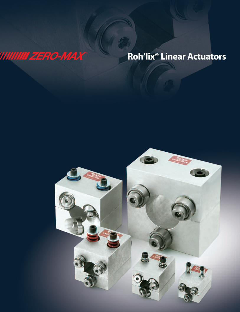
ROH’LIX® LINEAR ACTUATORS
The Roh’lix Linear Actuator is a device that convertsrotary motion into linear motion. The Roh’lix uses rollingelement ball bearings that trace a helix pattern along the shaft, which produces a Rolling Helix, or Roh’lix for short. Available sizes have thrust capacities rangingfrom 15 to 200 lbs (67 to 889 Newtons), shaftdiameters ranging from 3/8 to 2 inches (8 to 50 mm),and leads ranging from 0.025 to 6.00 inches (0.625 to 150 mm).
The Roh’lix Linear Actuator consists of six preloadedbearings that contact the shaft at an angle. When theshaft is rotated, the bearings trace out an imaginaryscrew thread, causing the Roh’lix to travel linearly along the shaft.
The thrust of the Roh ’lix is established by spring forcebetween the two block halves. The thrust force is
adjusted by the thrust adjustment screws on the top of the block, allowing the thrust setting to be fine-tuned to individual applications. When the thrust setting isexceeded, the Roh’lix slips on the shaft until the sourceof the overload is corrected. The ability to slip allows the Roh’lix to provide overload protection for theequipment on which it is used.
The amount of linear distance the Roh’lix travels per shaft revolution is called lead. The lead is determined bythe angle of the bearings in the Roh’lix block. The Roh’lixcan be manufactured with virtually any fixed lead up to3 times the shaft diameter. The lead, in combination withthe driveshaft speed, determines the linear travel rate. By changing either the lead or the driveshaft speed, you can change the rate of linear travel.

2www.zero-max.com Phone 800.533.1731 763.546.4300 Fax 763.546.8260
®
M � �
ROH’LIX® LINEAR ACTUATOR OPERATING CHARACTERISTICS
Roh’lix Life ExpectancyRoh’lix lifetime can range anywhere from 2 million to over 100 million inches of linear travel, depending on the applicationvariables. The following factors should be considered to maximizethe lifetime of Roh’lix: Thrust: Roh’lix lifetime is increased when the application thrust load is a smaller percentage of the unit's thrust rating.Selecting an oversized Roh’lix is advisable to achieve thegreatest lifetime of the unit.
Lead/Shaft Speed: Higher lead units will produce longerlifetime because fewer bearing revolutions will be required to move the same linear distance as a low lead unit. Also,reductions in the driveshaft RPM will increase lifetime. For a given linear speed, a higher lead will allow a lower shaftspeed, and the two factors in combination will work to yield a greater lifetime.
Overloading: Occasional slippage for short periods of time isacceptable. However, frequent or extended periods of slippagewill result in reduced lifetime of the bearings.
Other: Minimize sideloads and twisting loads to gain maximumlife from the Roh’lix.
LoadingThe Roh’lix is intended for axial loading. Sideloads and twistingloads (Figure 1) should be avoided whenever possible, as theycause uneven bearing loading and shorten lifetime.Whenever possible, the load weight on the Roh’lix should besupported by a separate linear bearing assembly. Wheresideloads cannot be avoided, the amount of the sideload shouldbe subtracted from the thrust capacity of the unit. The amount ofthe sideload should never exceed 50% of the actuator's thrustcapacity. If necessary, select an oversized Roh’lix to handle theseapplication conditions.
InstallationThe Roh’lix has a split-block for ease of installation. The twoblock halves can be assembled around the shaft, eliminatingthe need for removal of pillow-block bearings, coupling, etc.The split-block design is also a benefit for removal of theRoh’lix for service, such as bearing replacement.
Thrust AdjustmentThrust of the Roh’lix is set by one of three methods: 1) Adjust the thrust adjustment screws in increasing
amounts until thrust setting is enough to carry loadwithout slipping. This allows slippage before anoverload builds up an unnecessary thrust load causingreduced bearing life.
2) Use a spring scale to set the amount of thrust (Figure 1).This technique works where the thrust requirement isknown.
3) Use the thrust per turn rating (Figure 2) to determine the appropriate number of turns of the thrust adjustmentscrews. This technique also works where the thrustrequirement is known.
To set a given thrust on the Roh’lix, start with the thrustadjustment screws loose then tighten by hand until the screwhead lightly touches the top of the spring. Tighten bothadjusting screws one full turn.This will set the thrust as shownin the thrust column of Figure 2. Finish the thrust adjustment by rotating the additional turns as necessary.
Twisting Load
Axial loading
Side Loading
Figure 1
Figure 2
Model # Screw Length
Screw Size
Thrust per Turn
1 1.25 6-32 3 lbs.
2 1.50 10-32 17 lbs.
3 2.00 1/4-20 25 lbs.
4 2.25 1/4-20 25 lbs.
5 2.50 3/8-16 35 lbs.

3 www.zero-max.com Phone 800.533.1731 763.546.4300 Fax 763.546.8260
®
� �
Figure 2b
1. Determine Thrust Requirement.Horizontal Applications: F=µWVertical Applications: F=W+ µWF= thrust requirement (Lbs.)µ= Coefficient of friction W= weight of load being moved (Lbs.)
2. Determine Lead/ Driveshaft Speed/ Linear Speed.
Driveshaft RPM= 60 x Linear Speed Roh’lix Lead
Driveshaft RPM= speed of shaft driving the Roh’lix (RPM)
Linear Speed= travel rate of the Roh’lix (inches per sec.)
Roh’lix Lead= lead of the Roh’lix (inches per shaft revolution)
Leads are available from a minimum of 0.025 inch (.625mm) to maximum of3 times the shaft diameter. Drive shaft diameters may be as small as 3/8inch to as large as 2 inches. (8 to 50 mm)
Figure 2a
3. Select Roh’lix Model. Choose a Roh’lix Model from Figure 2a or 2b that has a thrust equal to or exceeding the thrust requirementdetermined in Step 1 and lead that fits the driveshaft RPM and linear speed needs from Step 2.
4. Verify Shaft Diameter. Driveshaft speed should be within the maximumrecommended driveshaft speed shown in Figure 3.
Inch Models Metric Models
Size Model Number
Shaft dia. (In)
Lead (In)
Thrust Rating(Lb)
1 1104 3/8 0.03 15
1111 3/8 0.10 15
2
2102 3/8 0.10 30
2114 3/8 0.20 30
2103 3/8 0.50 30
2101 1/2 0.10 30
2115 1/2 0.20 30
2104 1/2 0.50 30
2112 1/2 1.00 30
3
3123 1/2 0.20 60
3109 1/2 0.50 60
3128 1/2 1.00 60
3110 5/8 0.10 60
3145 5/8 0.50 60
3103 3/4 0.10 60
3107 3/4 0.75 60
3133 3/4 1.00 60
4
4118 1 0.20 100
4110 1 0.50 100
4111 1 1.00 100
4125 1 2.00 100
5
5106 1-1/2 1.00 200
5109 2 0.38 200
5112 2 3.00 200
Size Model Number
Shaft dia.
Lead (mm)
ThrustRating (newton)
11901 8 1.3 67
1902 8 2.5 67
2
2901 8 2.5 133
2902 8 15.0 133
2903 12 5.0 133
2904 12 15.0 133
2905 12 25.0 133
3
3901 12 2.5 266
3902 12 10.0 266
3913 16 2.5 266
3914 16 15.0 266
3915 16 25.0 266
4
4901 25 2.5 444
4902 25 5.0 444
4903 25 25.0 444
5
5901 40 10.0 889
5902 50 5.0 889
5903 50 50.0 889
HOW TO SELECT A ROH’LIX® LINEAR ACTUATOR
New Zero-Max Configurable 3D CAD Downloads.www.zero-max.com

4www.zero-max.com Phone 800.533.1731 763.546.4300 Fax 763.546.8260
®
M � �
C
AB*
D
GH
EF (MAX)
1600
800640480
320240
160
.375.500
.625 .750 1.000
1.500 2.0002.5003.000
ABC
101215
202530
303540
405060
506075
607090
7085105
80100120
90110135
100120150
110130165
120145180
130160195
140170210
150180225
160195240
170205255
180220270
190230285
Length (Inches)
Maximum Recommended Drive Shaft Speed
Figure 3
H
G
1.50(38.00 MM)
G
*Dimension at zero thrust setting.
Bearing Mounting Method
SpeedRPM
Roh’lix Sizes 1-5
Roh’lix Sizes 1-3
Roh’lix Sizes 4-5
ABoth ends supported
BOne end fixed other end supported
CBoth ends fixed
Length(Inches)
Length(Inches)
Length(Inches)
HOW TO SELECT A ROH’LIX® LINEAR ACTUATOR
SizeDimensions
units A B C D E F G H-TappedMounting Holes
1inch 1.14 1.66 1.12 0.57 1.62 2.25 0.75 #6-32 UNC x 1/4 DP
mm 29 42.2 28.6 14.5 41.3 57.2 19 M3 x 0.5 x 6.35 DP
2inch 1.52 1.91 1.5 0.76 2 2.81 1 #10-32 UNF x 3/8 DP
mm 38.6 48.5 38.1 19.3 50.8 71.4 25.4 M5 x 0.08 x 9.53 DP
3inch 2.02 2.69 2 1.01 2.5 3.42 1.25 1/4-20 UNC x 1/2 DP
mm 51.3 68.3 50.8 25.6 63.5 86.9 31.1 M6 x 1.0 x 12.7 DP
4inch 3 3.5 3 1.5 2.5 3.56 2.5 1/4-20 UNC x 1/2 DP
mm 76.2 88.9 76.2 38.1 63.5 90.4 63.5 M6 x 1.0 x 12.7 DP
5inch 4.5 4.68 4.5 2.25 2.75 4.68 4 1/4-20 UNC x 1/2 DP
mm 114.3 118.9 114.3 57.2 69.9 118.9 101.6 M6 x 1.0 x 12.7 DP
13200 Sixth Avenue North, Plymouth, Minnesota 55441-5509
Phone: 800-533-1731 (763) 546-4300 Fax (763) 546-8260 www.zero-max.com
ServoClass® CouplingsDesigned for demandingservomotor applications. Zerobacklash, high torsional stiffnesscoupling. Features flexible metaldiscs and keyless clamp-typemounting hubs. Couplings areRoHS compliant.
Schmidt® Offset CouplingsSchmidt® Offset Couplings aredesigned to handle high amountsof parallel offset up to 17.00".Standard models with torquecapacities up to 459,000 in-lbs.
Overload Safety CouplingsTorq-Tender® Couplings providereliable overload protection in anymechanical power transmissionsystem. Torque ranges from 2 to3000 in-lbs.
ETP® Shaft Locking ConnectionsDesigned for quick, easy andaccurate assembly of mounted shaft components. Both inch andmetric bore connections are available from stock.
Adjustable Speed DrivesEasy to install and maintenance free.Zero-Max Drives offer infinitelyvariable speeds from 0 rpm to 1/4 of input rpm. 5 models with torqueranges from 12 in-lbs to 200 in-lbs.
Crown® Gear DrivesCrown® Gear Drives are available with1:1 and 2:1 ratios. High quality AGMAclass 10 spiral bevel gears. Stainlesssteel shafts and aluminum housings arestandard on all Crown® Gear Drives.
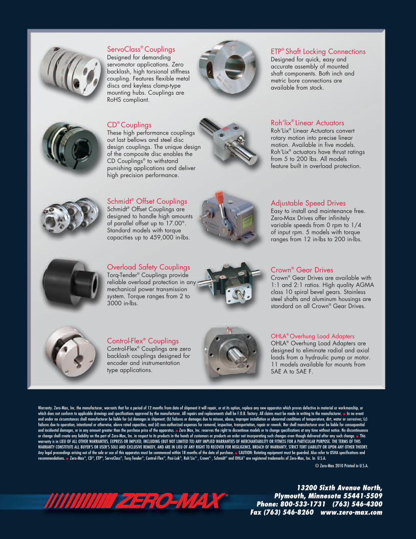
Roh’lix® Linear ActuatorsRoh’Lix® Linear Actuators convert rotary motion into precise linearmotion. Available in five models.Roh’Lix® actuators have thrust ratingsfrom 5 to 200 lbs. All models feature built in overload protection.
CD® CouplingsThese high performance couplingsout last bellows and steel discdesign couplings. The unique designof the composite disc enables theCD Couplings® to withstandpunishing applications and deliverhigh precision performance.
Control-Flex® CouplingsControl-Flex® Couplings are zerobacklash couplings designed forencoder and instrumentation type applications.
OHLA® Overhung Load AdaptersOHLA® Overhung Load Adapters aredesigned to eliminate radial and axialloads from a hydraulic pump or motor.11 models available for mounts fromSAE A to SAE F.
Warranty. Zero-Max, Inc. the manufacturer, warrants that for a period of 12 months from date of shipment it will repair, or at its option, replace any new apparatus which proves defective in material or workmanship, orwhich does not conform to applicable drawings and specifications approved by the manufacturer. All repairs and replacements shall be F.O.B. factory. All claims must be made in writing to the manufacturer. • In no eventand under no circumstances shall manufacturer be liable for (a) damages in shipment; (b) failures or damages due to misuse, abuse, improper installation or abnormal conditions of temperature, dirt, water or corrosives; (c)failures due to operation, intentional or otherwise, above rated capacities, and (d) non-authorized expenses for removal, inspection, transportation, repair or rework. Nor shall manufacturer ever be liable for consequentialand incidental damages, or in any amount greater than the purchase price of the apparatus. • Zero Max, Inc. reserves the right to discontinue models or to change specifications at any time without notice. No discontinuanceor change shall create any liability on the part of Zero-Max, Inc. in respect to its products in the hands of customers or products on order not incorporating such changes even though delivered after any such change. • Thiswarranty is in LIEU OF ALL OTHER WARRANTIES, EXPRESS OR IMPLIED, INCLUDING (BUT NOT LIMITED TO) ANY IMPLIED WARRANTIES OF MERCHANTABILITY OR FITNESS FOR A PARTICULAR PURPOSE. THE TERMS OF THISWARRANTY CONSTITUTE ALL BUYER’S OR USER’S SOLE AND EXCLUSIVE REMEDY, AND ARE IN LIEU OF ANY RIGHT TO RECOVER FOR NEGLIGENCE, BREACH OF WARRANTY, STRICT TORT LIABILITY OR UPON ANY OTHER THEORY.Any legal proceedings arising out of the sale or use of this apparatus must be commenced within 18 months of the date of purchase. • CAUTION: Rotating equipment must be guarded. Also refer to OSHA specifications andrecommendations. • Zero-Max®, CD®, ETP®, ServoClass®, Torq-Tender®, Control-Flex®, Posi-Lok®, Roh'Lix® , Crown® , Schmidt® and OHLA® are registered trademarks of Zero-Max, Inc. In U.S.A.
© Zero-Max 2010 Printed in U.S.A.