roedunet conference
292
ROEDUNET CONFERENCE NETWORKING IN EDUCATION AND RESEARCH SECOND EDITION IASI, ROMANIA, JUNE 5-6, 2003 Organizing Committee Traian IONESCU General Director, Ministry of Education and Research, Romania - president Dorin CARSTOIU - Director, Ministry of Education and Research, Romania Florin MANOLACHE- Carnegie Mellon University, Pittsburgh, PA, USA Eduard ANDREI - General Manager of RoEduNet, Romania Eugenie STAICUT - National Institute for R&D in Informatics Kalman PUSZTAI - Manager of RoEduNet Cluj Branch, Romania Octavian RUSU - Manager of RoEduNet Iasi Branch, Romania Scientific Committee Kalman PUSZTAI - RoEduNet Cluj - president Eduard ANDREI - RoEduNet Bucuresti, Romania Irina ATHANASIU - Politehnica University Bucuresti, Romania Oleg CERNIAN - RoEduNet Craiova, Romania Dan CRISTEA - Alexandru Ioan Cuza University, Iasi, Romania Valentin CRISTEA - Politehnica University, Bucuresti, Romania Calin ENACHESCU - RoEduNet Targu Mures, Romania Ionel JURCA - RoEduNet Timisoara, Romania Florin MANOLACHE - Carnegie Mellon University, Pittsburgh, PA, USA Octavian RUSU - RoEduNet Iasi Branch, Romania Alexandru STANCU - Alexandru Ioan Cuza University, Iasi, Romania Nicolae TAPUS - Politehnica University, Bucuresti, Romania Local Organizing Commitee Dumitru OPREA - Alexandru Ioan Cuza University, Iasi - president Toader JUCAN - Alexandru Ioan Cuza University, Iasi Octavian RUSU - RoEduNet Iasi Alexandru STANCU - Alexandru Ioan Cuza University, Iasi Dan CRISTEA - Alexandru Ioan Cuza University, Iasi Valeriu VRACIU - RoEduNet Iasi Manuel SUBREDU - RoEduNet Iasi Paul GASNER - Alexandru Ioan Cuza University, Iasi
Transcript of roedunet conference

ROEDUNET CONFERENCE NETWORKING IN EDUCATION AND RESEARCH
SECOND EDITION IASI, ROMANIA, JUNE 5-6, 2003
Organizing Committee Traian IONESCU General Director, Ministry of Education and Research, Romania - president Dorin CARSTOIU - Director, Ministry of Education and Research, Romania Florin MANOLACHE- Carnegie Mellon University, Pittsburgh, PA, USA Eduard ANDREI - General Manager of RoEduNet, Romania Eugenie STAICUT - National Institute for R&D in Informatics Kalman PUSZTAI - Manager of RoEduNet Cluj Branch, Romania Octavian RUSU - Manager of RoEduNet Iasi Branch, Romania
Scientific Committee Kalman PUSZTAI - RoEduNet Cluj - president Eduard ANDREI - RoEduNet Bucuresti, Romania Irina ATHANASIU - Politehnica University Bucuresti, Romania Oleg CERNIAN - RoEduNet Craiova, Romania Dan CRISTEA - Alexandru Ioan Cuza University, Iasi, Romania Valentin CRISTEA - Politehnica University, Bucuresti, Romania Calin ENACHESCU - RoEduNet Targu Mures, Romania Ionel JURCA - RoEduNet Timisoara, Romania Florin MANOLACHE - Carnegie Mellon University, Pittsburgh, PA, USA Octavian RUSU - RoEduNet Iasi Branch, Romania Alexandru STANCU - Alexandru Ioan Cuza University, Iasi, Romania Nicolae TAPUS - Politehnica University, Bucuresti, Romania
Local Organizing Commitee Dumitru OPREA - Alexandru Ioan Cuza University, Iasi - president Toader JUCAN - Alexandru Ioan Cuza University, Iasi Octavian RUSU - RoEduNet Iasi Alexandru STANCU - Alexandru Ioan Cuza University, Iasi Dan CRISTEA - Alexandru Ioan Cuza University, Iasi Valeriu VRACIU - RoEduNet Iasi Manuel SUBREDU - RoEduNet Iasi Paul GASNER - Alexandru Ioan Cuza University, Iasi

I
C O N T E N T S ALINA ANDREICA Internet Impact on Romanian Students............................................................................................... 1 DOINA BEIN, AJOY K. DATTA Anonymators: Privacy and Security on Internet................................................................................. 10 DOINA BEIN, AJOY K. DATTA, VINCENT VILLAIN Self-Stabilizing Routing Protocol for General Networks.................................................................... 15 WOLFGANG W. BEIN Malicious Internet Use and Homeland Security................................................................................. 23 TUDOR BLAGA, VIRGIL DOBROTA, DANIEL ZINCA, MIHAI VANCEA Mobile IPv6: Configuration and Trials............................................................................................... 27 MIHAELA BRUT An Open Source Proposal for Educational Web Site Development.................................................... 35 SABIN CORNELIU BURAGA An XML-based Semantic Description of Distributed File Systems..................................................... 41 EMIL CEBUC, KALMAN PUSZTAI, OTTO KREITER, FLORIN FLORIAN GigabitEthernet Testbed over Dark Fiber.......................................................................................... 49 CIPRIAN CIUBOTARIU Chaotic and Quantum Neural Networks............................................................................................. 54 CIPRIAN CIUBOTARIU Distribution of Quantum Information I. Quantum Entanglement....................................................... 59 ILINCA CIUPA Study on Whitebox Frameworks in Java............................................................................................. 66 CRISTIAN DUDA UBBInfo Search: A First Step towards the Paperless Office.............................................................. 71 CĂTĂLIN DANIEL GĂLĂŢANU, ELENA BĂRBIERU Docimological Principles Applied to the E-learning Tests................................................................. 77 CĂTĂLIN DANIEL GĂLĂŢANU, VERONICA GHICA, ELENA ERNU The Quality of Open Distance Learning- the Impact of the Constructivism Pedagogy...................... 82 PIROSKA HALLER Performance Study of Group Controllers Used in Collaborative Multimedia Applications.............. 86 MARIUS JOLDOS, KALMAN PUSZTAI Security Policies for RoEduNet........................................................................................................... 92 FLORIN B. MANOLACHE A Professional's Guide to an Economical, Secure, and Functional Computing Environment........... 100 ADRIAN PETRU MIERLUTIU A Rule Cache for iptables in Linux...................................................................................................... 108 IOAN MIHAILESCU, BOGDAN LOGOFATU, MICHAELA LOGOFATU, LUCA BOBOC-CORCOTOI, MARIUS MUNTEANU, ALINA MUNTEANU, MIRCEA FLORESCU, CRISTIAN LOGOFATU Virtual Campus and "eLearning" at University of Bucharest............................................................. 115 MADALINA MLAK From MBone to M6Bone..................................................................................................................... 119 BOGDAN MORARU, FLAVIUS COPACIU, GABRIEL LAZAR, VIRGIL DOBROTA Practical Analysis of TCP Implementations: Tahoe, Reno, NewReno................................................ 125 CRISTINA NICULESCU, RADU ION Pilot Cooperative System in Sustaining Project Management Activities............................................ 131 BOGDAN OANCEA, RAZVAN ZOTA The Design and Implementation of a Parallel Linear System Solver................................................. 136 IULIAN OPREA, DENISA NEAGU The Key Technologies behind the Business and Educational Presence on Web; an OS and Web Server Approach in SMEs and Romanian Educational Institutions................................................... 140 VICTOR-VALERIU PATRICIU, LIVIU RUSU, IUSTIN PRIESCU Data Mining Approaches for Intrusion Detection in Email System Internet-Based........................... 144 ERICH PEPLOW, PETER BOGATENCOV, TUDOR CIBOTARU, GRIGORY SECRIERU, VEACESLAV SIDORENCO, BORIS VARZARI Development of RENAM State and Infrastructure.............................................................................. 148

II
EUGEN PETAC, DRAGOS MUNTEANU A European Comparison of ICT Qualification Strategies in Training Institutions, Colleges, Universities and Vocational schools................................................................................................... 152 EUGEN PETAC, DOINA PETAC An Analysis of ICT Policy and Strategies in Romania in European Context...................................... 167 ION PIRSAN SS7 Overview....................................................................................................................................... 175 KALMAN PUSZTAI, OTTO KREITER, MARIUS JOLDOS, ZOLTAN SOMODI The IPv6 Pilot Project at the Technical University of Cluj-Napoca................................................... 185 KALMAN PUSZTAI, RAMONA MARFIEVICI Traffic Engineered Multicast in MPLS Domains................................................................................ 202 KALMAN PUSZTAI, LIVIU IUSAN, CRISTIAN MORARIU TROTICS - More than a Help-desk Tool for ROEDUNET................................................................. 206 SILVIU RIŞCO, ANTOANELA NAAJI IT Infrastructure Optimization Regarding the e-Learning Implementation........................................ 210 DANUT RUSU Protection Methods of Java Bytecode................................................................................................. 214 OCTAVIAN RUSU, FLORIN B. MANOLACHE Network Management Framework: A Distributed Virtual NOC Architecture................................... 221 GHEORGHE SEBESTYEN, KALMAN PUSZTAI New Networking Technologies in Control Applications..................................................................... 227 VEACESLAV SIDORENCO, VLADIMIR CICLICCI, SERGEI DOLENCO Heterogeneous Networks Management System having GIS and Web Based Interfaces..................... 232 SILVANA SOLOMON, CATALIN VARVARA Using XML-RPC in Secure Database Administration on the Web..................................................... 236 ALEXANDRU STANCU, LAURENTIU STOLERIU, MIHAI CERCHEZ The ODL Programs in the Moldova Region of Romania.................................................................... 242 EMIL STANESCU A Web Services Based Architecture for Improvement of the Transparency and Decision-making in Public Administration.......................................................................................................................... 245 ALIN SUCIU, KALMAN PUSZTAI, ANDREI DIACONU Enhanced Prolog Remote Predicate Call Protocol............................................................................. 252 ALIN SUCIU, KALMAN PUSZTAI, ANDREI VANCEA Prolog Server Pages............................................................................................................................ 257 MANUEL SUBREDU, OCTAVIAN RUSU, VALERIU VRACIU A Practical Solution to Detect DoS/DDoS Attacks............................................................................. 261 ION TUTĂNESCU, EMIL SOFRON Anatomy and Types of Attacks against Computer Networks............................................................... 265 MONICA VLADOIU, CATALINA NEGOITA Reflective Blended Methods for Teaching and Learning Operating Systems..................................... 271 DJORDJE VULOVIC, DEJAN BRKIC, ZORAN JOVANOVIC LDAP-based DNS Management System.............................................................................................. 278 RAZVAN DANIEL ZOTA, BOGDAN OANCEA E-learning in the Academic Context: Toward a New Economy of Education.................................... 282 CHRISTIAN CATALIN MITU Limitele dreptului de folosinţă asupra numelui de domeniu .ro. Reglementare şi aspecte de practică judiciară................................................................................................................................ 287

1
Internet Impact on Romanian Students
Alina Andreica “Babeş-Bolyai” University of Cluj-Napoca (BBU), Romania
Abstract
Nowadays, the electronic information and communication services offered by the Internet strongly influence our society by reducing time and space boundaries in obtaining and communicating information. The paper focuses on the impact of the Internet upon the young generation, our case studies being oriented towards Romanian students. We sustain our statements by administrating and anlyzing web questionnaires, which enabled us to perform a quantitative and qualitative research in the field we concentrated on.
The results show a considerably higher rate of Internet use in the academic medium (among students) than in the average Romanian population. An estimated percentage of around 90% Internet users in our student questionnaire sample gives a good indication on the extent of Internet use on Romanian youth (in particular, students), the most widely used Internet services being e-mail and WWW. The paper also proposes some sociological oriented interpretations on Internet use among Romanian students. 1. Introduction
In Romania, the average level of ICT (Information and Communication Technologies) implementation is quite low, because of the difficulties generated by the economic transition, the low average income of the population compared to other European countries and the communication infrastructure which was poorly managed during the '80s (we note that in this respect there had been significant improvements in the last years). On this general background, there had been estimated only
5-9% computer and Internet users from the whole Romanian population (GFK Marketing Research).
Neverthelss, the educational and academic medium and, more generally, the Romanian youth are characterized by much higher degree of Internet use, as we intend to prove in this paper. The Romanian Educational Network plays a significant role in improving and extending ICT implementation in the educational medium, which comprises a significant part of the Romanian youth. 2. Designing, Administrating and
Interpreting a Questionnaire for Internet Use among Romanian Students The aim of our study is to identify, quantify and
analize the impact of the Internet upon Romanian students by means of administrating a questionnaire and processing the results.
2.1. The Questionnaire
In order to evaluate the extent of Internet use
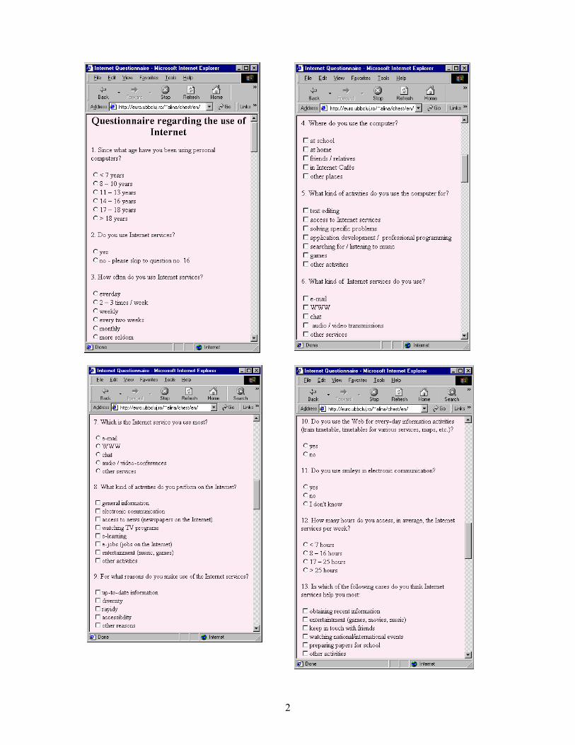
among Romanian youth and to reveal which are the most popular services and access reasons, we designed the questionnaire presented in the screen shots shown in Figure 1. We prepared it as a HTML web form in order to be administered efficiently and accessibly to a large number of subjects on a web interface. The questionnaire is publicly available at the following web addresses: • http://euro.ubbcluj.ro/~alina/chest - the
Romanian version • http://euro.ubbcluj.ro/~alina/chest/en - the
English version. Aiming at administrating the questionnaire
mainly among students in the Faculty of European Studies (BBU), and pupils from a neighbouring high-school, we proceeded by making some statistical considerations regarding the target population, in order so establish a representative sample.
2

3
Figure 1: The questionnaire

4
We performed a non-random sampling on our target population, comprising 3000 people, using the quotas method by the sex criterion. We intended to obtain a sample containing around 66 % female population and 34 % male population, as in the entire target group.
Along the period October 2002 - February 2003, we had 75 subjects - students and pupils - who filled in our questionnaire. Taking into account their gender distribution, as well as other characteristics which we present below, we can consider that our sample has a fairly good representativity for the target population of students. A possible drawback, which we intend to deal more thoroughly with in the future, relies in the fact that a group of Internet non-users could have eluded our research by simply
avoiding our web questionnaire. Along the administrating period, we periodically verified that the structure of our sample was being pursued. Nevertheless, we intend to continue our researches on the same target group, by finding new subjects, in order to obtain more positive results. 2.2. The Subjects
We had a total of 75 subjects, pupils and students
(over 16 years old). Our sample can be characterized by the following aspects, which we give in a suggestive graphical form:
1) Age distribution.
We encountered the following age categories: 23% between 16 and 17 years old, 24% between 18 and 19 years old, 24% between 20 and 21 years old, 20% between 21 and 22 years old and 12% - more than 22 years old. We note that we chose such refined age categories since we targeted mostly student population.
Age distribution
0% 23%
24%20%
21%
12% <16 years16-17 years18-19 years20-21 years21-22 years>22 years
2) Gender distribution. Our sample comprised 66.6% females and 33.3%
males; this proportion verifies the statistical trend for student population in our University (around 32% male – student population and 68% femal student population).
Gender distribution
33%
67%
MaleFemale
3) Professional background. Coincidentally, 33 % of our subjects declared
they have a human sciences background, while 67% stated an exact sciences one. This distribution is consistent with the target group.
Professional background
33%
67%
Exact sciences Human sciences
4) Attitude towards the questionnaire Attitude towards the questionnaire
42%
13%24%
6%15%
a pleasurean obligationamusingboring"inexpressible"
5) Mood (when filling in the questionnaire)
Moods
49%
24%
0%
15%
12%:);):(:|I don't know

5
2.3. Adminstrating the Questionnaire As mentioned above, we launched our
qustionnaire on the web. This contact method has considerable advantages, but also a few dissadvantages: good flexibility, good means for collecting a large amount of data, excellent speed for data collecting, good respond rate and minimum financial costs, fair control of interviewer responses, but poor control of the sample and possible representativity problems. We tried to underline its strengths and mend its weakness.
2.4. Data Processing
We gathered the response data from all our
subjects by means of a CGI program created for this purpose (each set of answers was retained in a file). We encoded each complete questionnaire and cancelled the incomplete ones. Afterwards, we imported the whole set of response data in Excel and processed it within specific worksheets.
2.5. Results and Interpretations
Atfer processing all the results, we can state that,
in spite of the drawbacks in Romanian societal management regarding the IT field (see [7]), Internet has a major impact upon the Romanian youth. Young Romanian people, as all young people around the world who can access Internet services, are extremely receptive to the novelty, the efficiency, the rapidity and the diversity of these electronic information and communication services. The results we obtained show an exponentially higher rate of Internet use than the average one in Romania (5-9% - see section 1), the reason relying in the high education target field.
The above statements are supported by the
following results:
1) 94.6% of our subjects use Internet services (question no. 5). This figure is extremely evocative for the degree of Internet use among Romanian students. Other activities they use computers for are: text editing (64% of our subjects), listening / searching for music (62.6%), electronic games (36%), solving various problems (25.3%);
2) Regarding the place from which students use the computer, 72% of our Internet user subjects access Internet cafés. This result suggests a high penetration of IT technologies in students’ every-day life and a fairly good offer on the I&CT market. The main reason in using paid Internet access is obviously the need for these services (they are willing to pay for I&CT servicse). 88% of our subjects access Internet services at
school, therefore we can state that the Romanian high education system makes available the new information and communication technologies on a large scale. 42.6% of our subjects use Internet services at home. This figure suggests a reasonable (for the central and east European region) and much higher rate than the average Romanian one ([7]) of Internet services penetration on the Romanian market. We deal again with paid services, which cover an information and communication need. The higher level than the average societal one is obviously generated by the high education system features.
3) Frequency of Internet accessing Regarding the frequency of Internet accessing,
more than half (56 %) of our subjects use these services on a daily basis (25.3 %) or several times a week (30.6 %). The total percentage of daily plus weekly basis – 90.6 % of the Internet user subjects – is quite impressive and indicates an extremely widespread use of Internet services among Romanian students. The complete chart of frequency distribution is given in figure 2.
Frequency of Internet access
25%
31%
34%
0% 7%3%daily %2-3 times / weekweekly %every 2 weeks %monthlymore seldom %
Figure 2: The frequency of Internet access
Neverthelss, these results are slightly counterbalanced by the average number of hours of Internet access – see figure 3: 72% of our subjects access Internet services less than 7 hours per week, in average (similar to the average in Romania – [7]). Therefore, we must conclude that the average duration for an access is quite small, which corresponds to the typical behaviour of a non-experienced consumer. On the other hand, we can happily say that our students are not Internet addicted yet ;-)
72.00
22.67
1.33 4.00
0
20
40
60
80
Perc
ent
<7 hours 8-16hours
17-25hours
>25hours
Number of hours / week
Average duration of Internet access
Figure 3: Average duration of Internet access

6
4) The most widely used Internet services are e-mail and WWW, with very close and impressive values: 94.6% - e-mail and 97.3% - WWW (from the subjects using Internet services). These striking figures underline the importance of the most popular Internet services; their similarity is also relevant for the comparable importance of the main information and communication services. Interesting is the fact that chat does not come in the top, but with a 32% percentage is well represented. Other Internet activities are quoted with 13.3%. We can notice that, as we expected, audio&video communcaitons are not well represented (10.6 %); the reason lies in the perfectible communication infrastructure [5], since multimedia sequences require large and high speed communication channels.
5) The most used Internet service For the most used Internet service, e-mail and
WWW are also "in competition". Nevertheless, it appeared that for our subjects e-mail was the most used (with 53.3%), whereas WWW was the most used service for 41.3% - see figure 4. We can interpret this distribution as a stronger need for communication, for contacting people or even
institutions, which is characteristic to teenager and early youth explorations. Satisfying the need of knowledge will closely follow.
The most used Internet service
54%41%
5%
e-mailWWWchat
Figure 4: The most widely used Internet servies
6) The latter conclusion is underlined by the distribution of activities that are performed by means of Internet services - see table 1; general information and electronic communication are again at the top (89.3%, respectively 69.3%). Keeping informed by accessing news on the Internet also has a significant value (52%). We consider the 24% percentage associated to e-jobs to be quite important and to suggest the e-way that society evolves on. E-learning is rated with 13.3%.
Activities Affirmative answers (%) Activities Affirmative answers (%)
General information 89.3% E-learning 13.3%
Electronic communication
69.3% E-jobs 24%
Access to news 52.% Entertainment 48%
Watching TV programs 6.6% Other activities 24%
Table 1: Distribution of activities 7) A possible quantifier for the importance of
Internet services for our subjects is their presence or absence in holiday destinations. For 45.3% of our subjects, holidays are old fashioned and the destination does not depend on the possibility of Internet access. But for 12%, the existance of Internet connection influences holiday decisions.
Influence of Internet access upon holiday destinations
12%
45%
43% yesnoit depends
Figure 5: The influence of Internet access upon choosing a holiday destination
One can notice a balance between the ones who do not choose holiday destinations taking into account the access to Internet services and those who make the choice based on Internet access or on a particular situation.
8) The utility of Internet services for our subjects is given in Table 2. The following motives are in top: obtaining recent information (78.6%), keeping in touch with friends (70.6%), preparing papers for school (68%). Since entertainment is quoted with (only) 26.6%, we can state that our students give mainly scientific, educational and social purposes to Internet services; the fact that Internet satisfies information and communication needs is again confirmed.

7
Aims Affirmative answers (%) Aims Affirmative answers (%) Obtaining recent
information 78.6% Watching national /
international events 26.6%
Entertainment 26.6% Preparing papers for school
68%
Keep in touch with friends 70.6% Other activities 14% Table 2: Utility of Internet services
9) The potential use of Internet services for
entertainment and spare time We prospected, with question 15, the potential
use of Internet services for entertainment and spare time, together with other favourite spare time activities of our subjects. They were required to rate various activities in respect with their preferences on a scale from 1 (do not like at all) to 7 (like very much). One can notice that all our subjects are interested in the entertaining aspect enclosed in Internet services. Moreover, the subjects who are reasonably interested (rate 5,6) in this aspect represent almost half of the sample (40%), while Internet "addicts" represent only 5.3%. We can conclude that Internet services are viewed as enjoyable activities.
Internet access as entertainment
3% 11%
16%
25%20%
20%5%
rate 1rate 2rate 3rate 4rate 5rate 6rate 7
Figure 6: Internet access as entertainment
10) Internet behaviour in respect with gender Regarding Internet behaviour in respect with
gender, we observe that the percentages we obtained are similar to the statistical gender distribution in our sample - see figure 7: male and female subjects use Internet services to the same extent.
Female subjects tend to use a little more often Internet services, as shown in figure 8. Here, percenteges are expressed in respect with the number of male / female subjects. One might also say that male subjects are more steady users - most of them access Internet at least once a week, while female subjects use Internet services either more often, or more seldom.
64.00 66.67
30.67 33.33
010203040506070
Perc
ent
Internetservices- females
%
Female%
Internetservices- males
%
Male %
Gender distribution for accessing Internet services
Figure 7: Gender distribution for accessing
Internet services
Figure 8: Gender distribution for accessing Internet services

8
Male subjects have a different behaviour and use much more information services (WWW is the most used service for 56 % of the male users), while female subjects are much more oriented towards communication (e-mail is the most used service for 58 % of the female users and chat is the most used service for 8% of the female subjects in the sample) - see figure 9. The fact that all chat users in our sample were female subjects is very relevant for their communicative nature .
58
34
8
4456
00102030405060
Perc
enta
ge
e-mail -female
WWW-
female
chat -female
e-mail -male
WWW- male
chat -male
Gender distribution for the most used Internet service
Figure 9: Gender distribution for the most used Internet service
Regarding the dependency of Internet services, both male and female subjects are influenced in similar manner by the presence or the absence of Internet services. Our question about how Internet access may influence a holiday choice is interpreted, from the gender point of view, in figure 10. We notice that the male -female proportion in our sample is respected by these distributions.
Concluding our gender interpretations, we must state that the above described gender distributions are also influenced by the specific male-female proportion in our sample - 33.3% male subjects and 66.6% female subjects.
In the future, we intend to enlarge our student sample in order to obtain more representative results and to extend our researches to other professional / age groups in order to have a more thorough image on the extent of Internet services penetration in the Romanian society. 3. Evolutions of Internet Impact. Conclusions of
the Study
Computer networks became genuine electronic information and communication media, which, sustained by an accessible software, tend to overpower classical means of communication. Internet services proved to be so useful on scientific, commercial and social fields, that people became more and more dependent of the new e-way. Moreover, not only classical means of information / communication started to be replaced by electronic ones, but more and more every-day activities became computer controlled: computer networks ensure remote access to various services,
consequently the person's physical presence becomes unnecessary. On this basis, many every-day activities received a new, electronic form: e-learning, e-commerce, e-banking, e-working, etc.; consequently, the information / knowledge based society evolved.
The new features of the information society were strongly promoted by computer networks and their applications. Taking into account the vivid rhythm that these transformation took place during the last decades and the continuous development of information technologies, which constantly emerge into our every-day life (in fact, computer history has less than 6 decades), we can imagine that the future of computers will also bring spectacular mutations into the human society.
In Romania, on the background of economic transition difficulties and of a perfectible societal management, investments in the IT field are insufficient, although the dynamic and growing software industry and especially the powerful force of IT specialists are definitely important prerogatives. Despite the transition difficulties, Internet impact among Romanian youth, and especially among student population, opened to innovation, is very powerful. The attractiveness of Internet information and communication services rely in their rapidity, flexibility, diversity, up-to-date and accessibility. This dynamic force will definitely impose future developments of information and communication technologies and infrastructure.
Our results show a considerably higher rate of Internet use in the academic medium (among students) than in the average Romanian population. An estimated 94% percentage of Internet users in our student questionnaire sample gives a good indication on the extent of Internet use on Romanian youth (in particular, students). The most widely used Internet services are e-mail and WWW; we noticed that male subjects are more likely to use information services, whereas female subjects' communicative nature is more oriented towards communication services, like e-mail and chat.
As a final remark, we state that Internet services have a major impact upon Romanian students. This statement is sustained both by our quantitative results (number of users, average time of use) and qualitative ones (types of services, satisfied needs). Our results are very different from the average ones in Romania since the high education medium, strongly relying on efficient information and communication means, is highly dependent on IT and, moreover, it even offers IT facilities. The main Internet service provider for the academic medium is RoEduNet; its recent and major improvements in band width and service quality have obviously had a strong and worthy impact upon Romanian students.
Taking into account the percentage of Internet users we obtained for our sample and the student and

9
high school pupil percentages in the Romanian population (2.46%, respectively 3.17% in 2001 [15]), we might approximate that up to 50% of the Romanian Internet users are young people. This estimation which emphasizes both the importance of the Romanian Educational Network and the openess of the Romanian young generation towards the flexibility and efficiency of modern I&CT. 4. References [1] Alina Andreica – Information and
Communication Facilities in Internet, "Babeş-Bolyai" Univ., Studia Europaea, XLIII, 1-2, 1998, p. 105-131.
[2] Alina Andreica, Cosmin Deac – E-commerce Security, paper presented at the VIth Congress “Cultura Europea”, Pamplona, Spain, 24-28 October 2000.
[3] Alina Andreica, Florin Bota, Horea Todoran – Alternative E-learning Model for Training European Union Experts in the Candidate Countries, Proceedings of the VIth Congress “Cultura Europea”, Pamplona, Spain.
[4] Alina Andreica, Horea Todoran – Societatea informaţională şi evoluţia informaticii. Prelucrări birotice, 338 p., Editura Fundaţiei pentru Studii Europene, Cluj-Napoca, 2001.
[5] Alina Andreica, Florin Bota – Informare şi comunicare în reţele de calculatoare, 244 p., Editura Fundaţiei pentru Studii Europene, Cluj-Napoca, 2001.
[6] Alina Andreica, Cristian Cucuruzan – E-commerce in Romania – Present Capabilities
and Problems, Studia Europaea, XLVI, 2, 2001, p. 3-30.
[7] Alina Andreica, Nicoleta Paina – Social Impact of the Internet upon Romanian Youth, paper presented at the VIIth Congress “Cultura Europea”, Pamplona, Spain, 23-26 October 2002.
[8] Anuţa Buiga - Metodologie de sondaj şi analiza datelor în studiile de piaţă, Editura Presa Universitară Clujeană, 2001
[9] Mihai Jalobeanu – Acces în Internet, Ed. Promedia Plus, 1996
[10] Philip Kotler - Marketing Management, The Millenium Edition, Prentice Hall, Upper Saddle River, New Jersey, 2000
[11] Philip Kotler, Gary Armstrong - Principles of Marketing, 9th Edition, Prentice Hall, Upper Saddle River, New Jersey, 2001
[12] Florin Vladimir Pilat, Sorin Popa, Sorin Deaconu, Florin Radu – Introducere în Internet, Ed. Teora, 1994.
[13] Traian Rotariu - Metode statistice aplicate în ştiinţele sociale, Editura Polirom, Iaşi, 1999
[14] Andrew S. Tanenbaum – Reţele de calculatoare, Ed. Computer Press Agora, 1997
[15] http://www.insse.ro/download/anuar_2001/zps/7_Education Research.zip (Institutul Naţional de Statistică din România / Romanian National Institute for Statistics)
10
Anonymators: Privacy and Security on Internet
Doina Bein Ajoy K. Datta [email protected] [email protected]
School of Computer Science, University of Nevada Las Vegas, USA
Abstract
In this paper we analyze different models of anonymators, systems that provide anonymous traffic on Internet. We start by presenting a simple model, which is one-node process and works at application layer of TCP/IP model architecture, and then we continue with distributed models such as Web Mixes and Tarzan, which work at a lower layer of TCP/IP (transport).
Keywords: Anonymity, chord ring, distributed system, chord ring, proxy server, relay.
1. Introduction
Internet is the largest distributed system in the
world. Processors communicate with each other through various communication lines, such as high-speed fiber optic cables, satellites, or telephone lines. The world has come to depend on the Internet at an increasing rate for e-commerce, communication, and many other essential services.
The model used for communication in Internet is mainly message passing. The data is exchanged through an interprocess-communication facility (IPC) provided by the operating system. It assumes the freedom of each processor to send whatever it wants, without forcing an authenticity at his part.
In the other model, shared memory, processes use map memory system calls to gain access to regions of memory owned by other processes. A process can access a region of memory owned by another pro-cess. Processes may exchange information by rea-ding and writing data in these shared areas. The form of the data and the location are determined by these processes and are not under the operating system's control. In this model, the authenticity can be easily implemented, but unfortunately, it is unfeasible for Internet. That is the reason why we will be using only message passing model in this paper.
Authentication refers to the ability to track the usage of the Internet to a given individual, on a spe-cific machine, during a specific time period, by the assignment of a unique username. It refers to the restriction of patron use of the Internet in an anonymous manner.
In this paper we analyze different models of anonymators, systems that provide anonymous tra-ffic on Internet. The TCP/IP model is the backbone
of Internet, so an anonymator can run at different layers. A simple model, one-process, which runs at application layer, is presented first. We continue with distributed models such as Web Mixes and Tarzan, which runs at transport layer. Advantages and disadvantages are presented for implementing anonymators at different layers of TCP/IP.
In section 2 we present definitions of privacy, anonymity, anonymator (subsections 2.1 and 2.2). In section 3 we present a one-process simple model (see subsection 3.1) and two distributed models, Web Mix and Tarzan (see subsection 3.2).
2. Definitions
Whenever one accesses a Web page, its operating
system gives information about his computer, more than he would like to provide. This data is included in the header of his request to access that particular web page. Some information is important in order to receive an answer back, but not all of them.
Based on the data received in his request packet, the destination processes it and extracts values for so called environmental variables. Table 1 presents the most sensitive and important environmental variables.
CLIENT_IP client IP revealed by proxy FORWARDED name of the proxy server
through which this document is being processed
REFERER URL of the HTML document which referred the remote client to this document
REMOTE_ADDR IP address of the remote client browser. If your are using an anonymous proxy, its IP will show here
REMOTE_HOST name of the remote client. If your are using an anonymous proxy, its IP will show here
Table 1. Sensitive environmental variables So, when one browses the web in search for
documents, news, he leaves a "fingerprint" which can be collected and used for later use (junk email, popup advertisement etc). Databases are created and exchanged without his knowledge (and permission!), by collecting every piece of electronic information

11
imaginable. As long there is a need for the services the Internet offers, this problem will persist.
Privacy refers to the ability of the individual to protect information about him. Definition 1 Anonymity is the privacy of identity.
In message-oriented services (such as email and newsgroup postings) two major problems to be solved are those of sender-anonymity, where the originator of a message wishes to keep his identity private, and of recipient-anonymity, where we wish to enable replies to a persistent persona. In contrast to message-oriented services, in online services, the World-Wide Web, online chat rooms, phones, videoconferences, and most instances of electronic commerce, we wish to enable two parties to communicate in real time, while allowing one or both of them to maintain their anonymity. The added challenges for online services stem from the increased difficulty involved in sending low-latency information without revealing identity via timing coincidences.
2.1 Surfing the Web Anonymously
In July 1993, when the Internet was booming, a
New Yorker cartoon presented a dog siting in front of his computer and saying: "On the Internet, nobody knows you are a dog". So why to reveal more than necessary when browsing the web?
In order to surf the Web anonymously, one needs the protection of an anonymator. (In the literature, you can find it also as anonymizer, but Lance Contrell, the owner of anonymator.com, has trademarked the word.) Definition 2 An anonymator is a third-party proxy server that acts as a middleman between the user and the site to be visited, ensuring privacy and security.
When the user wants to surf web pages at, say, the Yahoo site, its browser does not establish a direct Internet communication with http://www.yahoo.com, but instead asks his browser to communicate with http://anonymator_web_address:80/www.yahoo.comThe anonymator then makes the connection to www.yahoo.com without revealing any information about the user who requested the information, and finally forwards the information received from Yahoo to the user.
A proxy server, on receiving a request from an user, checks whether the requested page is in a list of previously downloaded pages (called cache). If it is, the answer comes back from the cache. If not, the request is forwarded to the server owning that web page. The browser does the dialog request-response and it is transparent for the user.
So an anonymator acts like a proxy server with additional features as: - it does not forward the user's email address to serve as a password for FTP transactions
- filters out application that can compromise anony-mity (cookies, Java applets, plug-ins, Active X etc). - does not forward any information which can identify the user or the user's machine (IP, port number, operating system etc) (see [1]):
- source IP address of the user - revealing information from the "User-Agent" MIME header - user's name from the "From" MIME header - previously-visited site from the "Referrer" MIME header
In this way, a user is protected as long it uses the anonymator services.
The basic principle of interposing a middleman server between user and web site is hardly novel. The Internet firewalls used by most companies rely on proxy servers, which use very similar technology to achieve their goal of eliminating direct connecti-ons between their employees and the outside network.
A perfect anonymous communication system is described theoretically in [2]. A perfect system must be able to protect from outside and inside attacks. By definition, it has to be fully distributed and not centralized.
An inside attack means that some nodes and/or links are under the control of the attacker (some components of the network can even act as oppo-nents). This is the worse case scenario, and it has to be taken in consideration. If the system were centra-lized, the center would have been the target of the attack and maybe could have been not only taken out of use, but become byzantine. An outside attack means that the endpoints communication links are under the control/observation of the attacker. This is the most common scenario.
A brief comparisons of the existing at that time anonymazing sites showed that the program called Web Mixes is better in terms of message coding, traffic analysis, flooding and collision attacks than the existing-then systems.
2.2 E-mailing Anonymously
Anonymous remailers and servers provide a
solution for those who wish to use e-mail or news services without revealing their identities. They can be used for one- or two- way anonymous communi-cation while keeping secret the identities of the participants.
Consider a user X who wants to send a message without revealing its identity. We consider the case in which the user wants also an answer to its message (and not an anonymous letter). X has to choose between using an anonymous server or an anonymous remailer.
An anonymous server provides anonymity, in the sense that:
1. the user has first to contact the server to establish an anonymous ID' that is unique to the person requesting it.

12
2. the server answers by creating the anonymous ID and linking the user's address to the ID.
From now, on every message coming from the user's e-mail address is automatically translated to the anonymous ID. User can also set up a password, which will protect the anonymous ID from anyone who is posing to send mail from the users address.
When the user wants to send anonymous mail through the anonymous server, he sends the message to the server and supplies the possible password and the address where the email should be sent in the beginning of the message. The server will strip the sender's address in the FROM -field of the message header and replace it by the anonymous ID so that the message seems to originate from the anonymous server.
If the recipient answers to the anonymized mail by replying to the anonymous address, the server will automatically translate the ID to the real e-mail address and forward the message there.
Anonymous servers can also be used to post articles in the newsgroups. The mechanism is otherwise the same as when sending mail, only the recipient's address is replaced by the name of the newsgroup. There may be differences between anonymous servers how they support posting anonymous messages to newsgroups. Some servers are specialized to send mail to only certain news-groups or newsgroups in a certain domain. Others may support posting any newsgroups that are not moderated or specifically haven't forbidden anonymized messages.
There are several weaknesses related to anony-mous servers. Several servers have been quite short-lived, because they have been forced to shut down by local administrators or pressure from network or government agencies. Some service providers are very strict not to hand over the identity of the anonymous users under any circumstances while others openly reveal the identities in the case of malpractice. Because of the nature of the service the server maintains a mapping between real addresses and anonymous IDs. This information can be confiscated by a court order. The traffic to these sites can be monitored to deduce the real identities. In all cases, the user places a high degree of trust in the anonymous server operator.
An anonymous remailer is a program that can be set up on a regular user account without the help or knowledge of the system administrator.
The remailer process reads the incoming mail, strips the address of the original sender and resends the message.
The problem with remailers is that the services seem to be somewhat unstable. They may be opera-ting without the system administrator's knowledge and therefore remailers come and go. Generally remailers don't support anonymous return addresses
either. There are also less formal ways of achieving anonymous mailing or posting to newsgroups.
Generally these involve connections to Unix communication ports using SMTP mail or NNTP news protocols to submit a message directly to a server with arbitrary field information. Most system administrators view these practices in a hostile way. The mechanism is quite rarely used and sometimes it is possible to track down the originating site.
3. Models of Anonymators
The backbone communication model for Internet
is TCP/IP. One can provide anonymity by working at different levels of this model. The application has to be correct, efficient in term of data and time, reliable, and adaptive.
When choosing the lower layers, one needs to have root or equivalent privileges, because he has to collect the packets using applications as Windump or Tcpdump (based on PCap library functions). This will ensure complete control over the traffic and what does go to the upper levels of the system. The advantage is that, most of the time, the application runs transparent and with a tolerable loss of effici-ency. So the effort to incorporate anonymators into existing designs and without changing applications is minimized. But one has to be careful about the changes he may make to the message packets (see the Tarzan model as example).
By choosing the application layer, he can enjoy little work in terms of the data that has to be parsed.
2.1 Simple Model
Here is an example of a simple anonymator that
works at application level. When one accesses a web page, his browser
sends a HTTP request. Take a look at the format of the request (Figure 1) and see what is necessary and what can be replace by some goofy values.
HTTP/1.0 request HTTP/1.0 reply
request-line headers (0 or more) <blank line> body (only for a POST request)
status-line headers (0 or more) <blank line> body
Figure 1. HTTP/1.0 message format One can either set up his browser to avoid some
unnecessary fields, or he can do it manually, by writing a program to do so. This program will be a service running at some port number in his machine, so it has to have a socket associated port number and type of service). One can choose either UDP or TCP.
Then when a packet is received, the sensitive and unnecessary fields will be replaced with some values and the updated packet will be forwarded to the Internet cloud. When the answer comes back, what one has to do is to just forward to his browser's port.

13
Putting all the pieces together, the traffic will look like in the Figure 2.
Figure 2. Traffic for a simple anonymator
One will have to launch the program running in
an infinite loop at some specific port number port_no. (Make sure you don't pick one that is already in use). The program will act as a proxy server. The best is if one can do it on a different machine whose IP is not closely related to his.
Then he specifies to his browser to use a proxy server running at some IP address and port_no. In case he has already a proxy server, he has to overwrite its information with the ones regarding the new program.
This won't work with URLs that use encryption. For example, an Apache server runs at port 443 and provides secure services. In order to work, it has to communicate directly to his browser. After the first contact is done and both sides exchange certificates, the communication moves to other ports. So, whenever one wants to access a web page which starts with https//..., he cannot use this method of anonymizing the traffic.
This is just a simple method, and it won't resist to any sniffing or centralized attacks by denial-of-service. The timings of receiving the original packet and the sending of the updated packet are about the same, so someone sniffing the traffic can observe these similarities.
A way to solve this issue is to use a set of mix relays, defined (but not implemented) by David Chaum (see [3]).
3.2 Distributed Models
Defined by David Chaum (see [3]), the mix
relay model is composed of a small number of relays (mix servers), each using a public key encryption. On receiving a request for an address A, a mix i encrypts it using public key KA, appends the address A, then encrypts everything with mix's public key Ki, and forwards to another mix. For decrypting, a mix uses its private key. Onion Routing (see [4,5] ), Freedom Network (see [6]) have implemented this model, using a fixed, small
number of mixes. But they were not fault tolerant and did not provide enough protection against attacking or blocking.
The Web Mixes (see [2]) and the recently Tarzan (see [8]) have outcome these issues.
To prevent timing attack, the dummy messages have to be created, and both the incoming and outgoing messages must have constant length (see adaptive chop-and-slice algorithm in [2]). To prevent flooding attacks that can happen quite often in Internet, a solution similar to round-robin algorithm is proposed (see ticket-based authentication system in [2]).
If the network has small number of nodes, then is more vulnerable to individual nodes/links failures/byzantine. A peer-to-peer approach called Tarzan (see [8]) overcomes this by providing nodes chosen from a large pool of volunteer participants. The graph model is a Chord ring: new participants join by contacting an existing relay and discovering its set of neighbors (see [7]). Each node publishes a public key, generated locally when it joins the network, and it is the only one knowing the corresponding private key. In a n node Chord ring, a node is connected with nodes situated at the distance 2m, m ∈ 0,1, ... log(n)-1. So it needs to maintain information only about O(log n) other nodes in the ring. Figure 3 shows as example the chord ring of dimension 8.
Figure 3. Chord ring of dimension 8 The packets are routed (using UDP) through a
randomly chosen sequence of peers using public-private key encryption. Each peer on the path picks a random peer, by generating a random lookup key and finding that key's successor (the successor of a key is the node with the smallest ID greater or equal to that key).
When entering the network, a forwarder hides the client IP and origin ports for TCP and UDP packets. The forwarder transforms the client IP into a random address taken from a reserved private address space (see Figure 4).
When leaving the relays network, this private address is translated by a server PNAT (pseudony-mous network address translator) to one of PNAT's real addresses. The answer packets enjoy the same treatment in reverse way.
client computer (browser)
simple anonymator (one-node process)
Internet cloud
Get <webpage> original packet
Get <webpage> original packet
Get <webpage> sanitized packet
receive <webpage> original packet
receive <webpage> original packet
receive <webpage> original packet
0
1
2
3
7
6
54

14
Figure 4. Overview of Tarzan architecture Application level protocols that leak
information (as HTTP) need an extra sanitizing before sending the packet outside.
4. Conclusion
By using a round robin algorithm, a distributed
system can protect against flooding, which is a denial of service attack (DoS), but it cannot protect against distributed denial of service (DDoS). In order to facilitate DDoS, an attacker uses several hundred to several thousand compromised hosts to orchestrate an attack.
Because the compromised hosts are different (they have different IP addresses), the round robin algorithm gives them different quanta of time, so a mix can get flooded in a situation of DDos attack. Even if one tries to maintain an access list, this list can get too large to be stored in that situation.
By exploring different network models, a solution for these needs should be found.
5. References [1] Justin Boyan, "The Anonymizer", CMC Magazine,1997, www.december.com/cmc/mag/ 1997/sep/boyan.html [2] Oliver Berthold, Hannes Federrath, Marit Kohntopp, "Anonymity and Unobservability in the Internet", Proceedings of the 10th Conference on Computers, Freedom and Privacy, 2000, pp. 57-68 [3] David Chaum, "Untraceable electronic mail, return addresses, and digital pseudonyms", Communications of the ACM, 1982(4) [4] Paul F. Syverson, David M. Goldschlag, Michael G. Reed, "Anonymous Connections and Onion Routing", Proceedings of the 18th Annual Symposium on Security and Privacy, IEEE CS Press, Oakland, CA, May 1997, pp. 44-54 [5] David M. Goldschlag, Michael G. Reed, Paul F. Syverson, "Privacy on the Internet", INET 1997, Kuala Lumpur, Malaysia, June 1997
[6] Ian Goldberg, Adam Shostack, "Freedom Network 1.0 architecture" Zero-Knowledge Systems, Inc., November 1999, http://www.homeport.org /~adam/zeroknowledgewhitepapers/archnotech.pdf [7] Ion Stoica, Robert Morris, David Karger, M. Frans Kaashoek, Balakrishnan, "Chord: A Scalable Peer-to-peer Lookup Service for Internet Applications", Proceedings of the ACM SIGCOMM '01 Conference, San Diego, California, August 2001, [8] Michael J. Freedman, Robert Morris, "Tarzan: A Peer-to-Peer Anonymizing Network Layer", Procee-dings of the 9th ACM Conference on Computer and Communications Security (CCS 2002), Washington, D.C., November 2002, pp. 44-54
client app
client router
relay
relay
relay relay
relay
relay
relay
PNAT
Internet

15
Self-Stabilizing Routing Protocol for General Networks
Doina Bein Ajoy K. Datta Vincent Villain School of Computer Science, University of Nevada Las Vegas, USA
School of Computer Science, University of Nevada Las Vegas, USA
LaRIA Universitè de Picardie Jules Verne, France
[email protected] [email protected] [email protected]
Abstract
Given an asynchronous network with at most nodes we present a self-stabilizing distributed algo-rithm for routing (nodes can be added or can crash at any time, so their number can vary up to the upper bound n). It starts in some arbitrary state, with no knowledge of the network architecture and eventually builds in each node a correct routing table regarding the t closest neighbors (t depends on the network needs: it can be n when each node needs to know shortest paths to all other nodes, or less when we need only partial knowledge). The size of the table in any node v is O((t + ∆v) log(n)) bits (∆v is the degree of node v), and a total of O(n t log(n)) bits per network. The stabilization time of the algorithm is O(d+c) time units (d is the maximum diameter of the network, and c is a large constant depending on the local computation time of a node).
Keywords: Asynchronous network, distributed algorithm, fault tolerance, routing, self-stabilization.
1. Introduction
`Routing schemes implemented in point-to-
point communication networks deliver messages between nodes ([1,2]). Each node maintains a routing table and it is important to update the routing scheme dynamically in case of network change (nodes can be added or conceivably crash.) When topology changes occur frequently in the network, a cold restart can become every expensive in terms of time and resources.
BGP (Border Gateway Protocol) provides the routing protocol that supports the Internet backbone. BGP servers must maintain routing tables that include all of the external addresses on the Internet! Routers use BGP to communicate with their intermediate neighbors to exchange their "routing tables" in order to inform each other about which IP ranges the router can forward.
The most general technique of designing a system to tolerate arbitrary transient faults is self-stabilization ([3]). A self-stabilizing system is guaranteed to converge to the intended behavior in finite time, regardless of the initial state of the nodes and initial messages on the links. In a distributed self-stabilizing routing algorithm, a node, with no
initialization code and having only local information, has to achieve a global objective, to build a correct routing table with limited information regarding routing toward its closest nodes.
1.1 Related Work
It is known ([4,5,6]) that the memory require-
ments of a routing scheme are related to the worst case stretch factor the routing scheme guarantees. Peleg ([6]) showed that any universal routing strategy that can achieve a stretch factor s≥1 must
use a total of Ω( 421
1+
+nn ) bits of routing information
in the network. Several routing strategies have been proposed
which achieve an almost optimal efficiency-space relation. Specifically, Peleg ([6]) proved that for every graph and every integer k ≥ 1 it is possible to construct a hierarchical routing scheme with stretch factor O(k) which uses a total of Ω( knk /113 + log n) bits and labels each node with O(log2 n) bits. The scheme has a few drawbacks: it is not name-independent (it relabels the nodes with new names), it does not bound the local memory requirement of a node, and finally, it assumes a unit cost on the links of the network. Other hierarchical routing methods ([4,5]) avoid these problems but at the price of non-optimal efficiency-space. But the major disadvantage of all proposed hierarchical routing strategies is a complex decision function at the nodes, which becomes a bottleneck in the case of high-speed networks.
In 1973, Dijkstra introduced the notion of self-stabilization in the context of distributed systems ([3,7]). He defined a system to be self-stabilizing when, “regardless of its initial state, it is guaranteed to arrive at a legitimate state in a finite number of steps”. A system, which is not self-stabilizing, may stay in an illegitimate state forever.
Fault-tolerance is an important issue in designing network routing protocols since the topology changes due to the link/node failure or recovery. Self-stabilizing topology-update problems are discussed in [8,9].

16
1.2 Contributions In this paper we propose a fault-tolerant
distributed algorithm that can work in a general asynchronous network. The algorithm starts with no knowledge of the network architecture and progressively builds a correct routing table with information regarding the closest nodes that can be used further for different types of routing (hierarchical, compact, interval etc).
It supports fault causing nodes and link failures and additions of nodes and/or links, and it is guaran-teed that it will reach a correct state in finite time (it is self-stabilizing). We assume that the maximum number of nodes in the network is n (nodes can be added or can crash at any time, so the number of nodes can vary but n is the upper bound).
The tasks are fairly distributed among the nodes and each node builds its own routing table based on the information gathered online up to the current moment. So for a node v, the routing table size is O((t + ∆v) log(n)) bits (∆v is the degree of node v). The value chosen for t depends on the network needs: it can be n when the node needs to know shortest paths to all other nodes, or less when we need only partial knowledge). The total amount of information stored in all the nodes in the graph is O(n t log(n)). The stabilization time of the algorithm is O(d+c) time units, where d is the maximum diameter of the network, and c is a large constant depending on the local computation time of a node.
1.3 Outline of the Paper
We start section 2 by giving general definitions
regarding distributed systems and self-stabilization, and continue with our main contribution, the self-stabilizing distributed routing algorithm. We then prove the correctness of the algorithm in Section 3 and we give some concluding remarks in section 4.
2. Self-Stabilizing Distributed Routing Algorithm (SRS)
In this section we define the self-stabilizing
routing algorithm. We present some general notions, and continue with the self-stabilizing algorithm.
2.1 Definitions
Distributed systems are a class of
multiprocessor systems, where the nodes have own memory. The nodes communicate by messages, with two actions: send(message) and receive(message). If nodes pi and pj need to communicate, they must send/receive messages from each other; a communication link (bi-directional channel) must exist between them. Messages sent by a node can be either fixed or variable size. Our algorithm is asynchronous, which means that is guaranteed to run
correctly in networks with arbitrary timing guarantees. A very common assumption is to bound the interval of time for transmitting a message, called timeout, after which the message is considered lost.
Each node starts with a unique ID and initially knows only its direct neighbors. Edges are labeled by distance values. Every node p can distinguish its entire links. The variable Np refers to the set of the direct neighbors of p, arranged in some arbitrary order pp. The number of neighbors of p, |Np|, is called the degree of p and is denoted by ∆p. We assume that Np is maintained by an underlying local topology maintenance protocol that it can alter its values in case of changes in the network (failures of nodes, or links, or both.)
We can order all the other nodes with respect to the distance relation and choose the set t-ball Bv(t) as the first t nodes according to the node ascending ordering ([10]). The t-ball defines the closer nodes, and does not always contain all the neighbors of the current node.
We cannot bound the moment of time when a message can be received (since the system is asynchronous), and we cannot wait forever to receive all the messages sent by other nodes in order to construct a correct t-ball. So we relax the definition of t-ball to fit to an asynchronous algorithm: Definition 1 A partial t-ball for a node v, Bv, is a set of t nodes, with the length of the path toward v within the t lowest values received by the node until a certain condition becomes true.
In the description of the algorithm, we use the word t-ball instead of partial t-ball, by a slight abuse in notation.
The program consists of a set of global variables and a finite set of actions. Each action is uniquely identified by a label and is part of a guarded command: <label> :: <guard> → <action>
The guard of an action is a Boolean expression involving the global variables and/or local variables. The action can be executed only if its guard evaluates to true. We assume that the actions are atomically executed: the evaluation of a guard and the execution of the corresponding action, if it is selected for execution, are done in one atomic step.
In the system, one or more nodes execute an action and a node may take at most one action. This execution model is known as the distributed daemon. We assume a weakly fair daemon, meaning that if node p is continuously enabled, p will be eventually chosen by the distributed daemon to execute an action. A network protocol is a set of node programs, one for each node.
Each component of a system (node or link) has a local state, which is the ID of the node and the values of the program variables. We define the global state of a system as the union of the local state of its components as well as the messages on links.
A self-stabilizing system S guarantees that, starting from an arbitrary global state, it reaches a legal global state within a finite number of state

17
transitions, and remains in a legal state unless a change occurs. In a non-self-stabilizing system, the system designer needs to enumerate the accepted kinds of faults, such as node/link failures, and he must add special mechanisms for recovery. Generally, not all types of faults are taken in consideration, and an obscure error such as a memory corruption can provoke a general reset of the entire system. Ideally, a system should continue its work by correctly restoring the state of the system whenever a fault occurs ([11,2]).
Let X be a set. x a Q means that an element x ∈ X satisfies the predicate Q defined on the set X. We define a special predicate true as follows:
for any x ∈ X, x a true. Let P be a distributed system and R and S
predicates on the states of P. R is closed if every state of the computation of P that starts in a state satisfying P also satisfies R. R converges to S in P if R is closed in P, S is closed in P, and any computation starting from a state satisfying R contains a state satisfying S.
Definition 2 P stabilizes to R iff true converges to R in P.
2.2 Routing Algorithm
The purpose of the algorithm is to construct a
correct routing table in each node with information regarding routing to the closest nodes in the network. For each node v it selects in the t-ball Bv the t closest nodes (t is decided in advance), and also it considers all the direct neighbors of v . The routing table called H will contain at most t + ∆v entries.
Each node v maintains several global variables of different types. The underlying layer of topological maintenance protocol computes the variable Nv, the set of the neighbors’ IDs of the node v (set of integers). The others are calculated and used by the layers of the algorithm: • B = the list of nodes IDs situated in the t-ball Bv of
the node v • updated = true when the t-ball is updated
(Boolean) • Rcvd_IDs = the set of IDs of other nodes known
by the current node • H = a linked list with information regarding the
nodes from B. An element has three fields: - dest = destination ID (integer) - neighbor = the neighbor which is the first node
on the path to dest (integer) - distance = the distance toward dest or 0 (int) - direct = true if dest is a direct neighbor and the
direct link is the shortest (Boolean) The list H is maintained in ascending order of
the distance value and has several functions that help us to retrieve information from it: • Give_IDs(H) = returns all the IDs (field id) in H,
or null if H is ∅ • G(H, id) = returns the element of H with the given
id if it exists, or null otherwise We consider the following notations: - v ∈ H means v ∈ Give_IDs(H) (e.g. H ⊆ B means Give_IDs(H) ⊆ B) - H[id] means G(H,u) (e.g. H[u].neighbor means (G(H,u)).neighbor).
There are other functions that we use: Remove_ID(id, H, B) = remove the element with given id from B and H Maximum_Distance( B, H) = selects the id of the node which is in B that has the maximum distance and also is not a direct neighbor NewCell( B, H, id, ...) = creates a new cell for id in H with the fields’s values specified, and adds id to B
The general algorithm has two layers:
Algorithm 2.1 SRS Self-Stabilizing Routing Scheme
A.01 Error_Correction A.02 Calculate_Ball
2.3 Error_Correction Error_Correction has the role to broadcast
periodically (a timeout is given) a message DIST with the node ID and the distance to that node, initially 0, to all its neighbors. These messages will be forwarded to other nodes, if they satisfy some distance criteria (such that the network doesn't get flooded) to help them calculate the distance to the current node. Eventually discrepancies in the global variables are detected and then the entire construction of the SRS scheme must start from scratch. In this case, all the global variables are reset to null or false, in order to start a fresh phase.
Algorithm 2.2 Error_Correction
Messages DIST sender: the ID of the sender
dist: the length of the path the message went through
LOST id1: the sender ID id2: the ID of the other node adjacent to the crashed link
Local variables id, nb, nbr: int Predicate ≠≡ HBerror \( ∅) Macro RESTART = reset Calculate_Ball and set
the global variables to their default values Actions: 1.01 timeout →
/* node v broadcasts the message DIST */ 1.02 SEND DIST(IDv,0) TO all nb ∈ Nv 1.03 error → RESTART 1.04 ∃ id ∈ H: H[id].direct = true ∧ id ∈ Nv ∧ length(link to id) ≠ H[id].distance → 1.05 RESTART

18
1.06 ∃ id ∈ H: H[id].direct = false ∧ id ∈ Nv ∨ H[id].neighbor = id → 1.07 H[id].distance := length(link to id) 1.08 H[id].direct := true
Macro RESTART R.01 B,H := ∅ R.02 Rcvd_IDs := IDv 2.4 Calculate_Ball
The algorithm Calculate_Ball gathers data
about the neighborhood. The DIST messages from the other nodes are processed and the first t lowest distances, breaking ties by increasing node ID, are stored in the data structure
H together with the node IDs (stored also in the set B.) So far, Bv is computed in the set B and the corresponding links are labeled dynamically with the IDs from the set B.
The set B should contain t nodes with the lowest t distances to v . Whatever is stored in B, is stored also in H, with additional data regarding the distance to those nodes and the neighbors of v toward them. So we make further tests on H instead of B . Besides the nodes in B, H contains also information regarding the direct neighbors of v.
In order to detect eventual discrepancies, each node sends its t-ball B to each neighbor. From [10], we know that: if u ∈ Bv then for every node x on the shortest path from v to u, u ∈ Bx.
The way a node v selects its nodes in B is by comparing different distances received from all the neighbors that also includes those nodes in their t-balls. Checking the other t-balls help us to eliminate wrong nodes and cycles in delivering messages.
On receiving a message DIST from a neighbor nbr, if the message contains its own ID (DIST.sender = IDv), discard it. Otherwise, process the message and eventually broadcast it to the other neighbors (if any). Message processing means: - add the length(link to nbr) to the field distance in the message - if the updated distance is within the top of the t lowest distances, breaking ties by increasing node ID, the ID is stored in B and H, and the message will be broadcast to all the other neighbors. - otherwise, discard the message.
Algorithm 2.3 Calculate_Ball
Messages BALL Sender: the ID of the sender B : the set B
dest : the ID of the destination CHECK sender: the sender ID, a
neighbor of the current node BN: the t-ball of the sender HN: the data structure H of the sender
DIST sender: the ID of the sender dist: the length of the path the message went through
LOST id1: the sender ID id2: the ID of the other node adjacent to the crashed link
Local variables id, u, nb, nbr : int /* elements in Nv*/
updated, to_send : Boolean Macros REMOVE = eliminate a wrong node
input id: int /* wrong node to be removed */ N: set of int /* the set of neighbors to
be warned about */ SEND_NBRS = send DIST messages to a set of neighbors and update some local variables UPDATE = update the data structure B and H
input id, dist ,nbr: int Actions 2.01 B ∪ IDv \ Rcvd_IDs ≠ ∅ → RESTART
2.02 ∃ id ∈ H:(id ∉ Nv ∧ H[id].direct = true) ∨ H[id].neighbor ∉ Nv →
/* id is a wrong node and remove it from B and H */
2.03 REMOVE (id, Nv)
2.04 B = ∅ → 2.05 Rcvd_IDs := IDv 2.06 H := ∅
2.07 Upon RECEIPT of DIST(s, dists) FROM neighbor nbr → 2.08 if (s ≠ IDv) 2.09 then 2.10 dists := dists + length(link to nbr)
/* update the information in B, H */
2.11 UPDATE (s, dists, nbr) 2.12 endif 2.13 Upon RECEIPT of LOST(id1,id2) FROM neighbor nbr → 2.14 if (id2 ∈ H ∧ H[id2].neighbor=id1) 2.15 then 2.16 REMOVE(id2,Nv \ nbr) 2.17 endif 2.18 Upon RECEIPT of CHECK(s, Bs, Hs) FROM neighbor nbr → 2.19 if (s = nbr) 2.20 then 2.21 for all (u ∈ B ∧ u ≠ s ∧ H[u].neighbor=s) 2.22 if (u ∉ Bs) ∧ (u ∈ Bs ∧ H[u].distance ≠ Hs[u].distance + length(link to nbr)) 2.23 then 2.24 REMOVE (u, Nv) 2.25 endif 2.26 endfor 2.27 endif

19
Macro REMOVE (id, N) R.01 Remove_ID (id,H,B) R.02 SEND LOST(IDv,id) TO all nb ∈ N R.03 Rcvd_IDs := Rcvd_IDs \ id Macro SEND_NBRS /* the message DIST is forwarded to the other neighbors */ S.01 SEND DIST(s, dists) TO all nb ∈ Nv \ nbr S.02 updated := true Macro UPDATE (id, dist, nbr) Local variable ID_max_dst : int U.01 Rcvd_IDs := Rcvd_IDs ∪ s U.02 if (id ∈ B) U.03 then U.04 if (id ∈ H ∧ (H[id].distance > dist ∨ (H[id].distance < dist ∧H[id].neighbor = nbr))) U.05 then U.06 H[id].distance := dist U.07 H[id].neighbor := nbr U.08 H[id].direct := false U.09 SEND_NBRS U.10 endif U.11 else U.12 if (|B| < t) U.13 then U.14 NewCell (H, B, id, dist, nbr, false) U.15 SEND_ NBRS U.16 else U.17 ID_max_dst := Maximum_Distance (B,H) U.18 if (H[ID_max_dst].distance > dist) ∨ H[ID_max_dst].distance = dist ∧ ID_max_dst > id)) U.19 then /* id is inserted and ID_max_dst is removed */ U.20 Remove_ID (ID_max_distance, H, B) U.21 NewCell (H, B, id, dist, nbr, false) U.22 SEND_NBRS U.23 endif U.24 endif U.25 endif
3. Correctness
All the proofs are made for a generic node v.
We show that the partial t-ball B will eventually contain only correct IDs.
For updating B, v receives only DIST messages with correct distances. Besides the removal of the wrong IDs from B (Properties 1 and 2), we have to show that B gets emptied at most once (by executing RESTART) in every execution of the algorithm (Lemma 1), such that the routing table H will eventually contain only correct information.
Using Theorem 1 and Lemma 2 we prove that the algorithm stabilizes in O(d + c) time units,
where d is the diameter of the network and c a large constant. Therefore SRS constructs a routing scheme in polynomial time and it is self-stabilizing also.
3.1 A Correct T-ball
To calculate the t-ball B for an arbitrary node v
in the network, we use guarded commands in the algorithm Calculate_Ball and some guards in Error_Correction.
Adding nodes to B is done automatically, and the macro UPDATE in Calculate_Ball takes care of it. The main concern is to remove the “bad” nodes, with invalid information in H and/or B. First, we show that the partial t-ball B will contain only correct IDs, and the wrong IDs from B are removed (Properties 1 and 2). Next, we prove that B can become ∅ at most once, so B converges to a correct t-ball (Lemma 1).
We have the following observations, most of them referring to macro UPDATE in Calculate_Ball. Observation 1 For ∀ u ∈ Bv, Hv[u].distance contains the lowest distance received toward u (lines U.10-13.) Starting from an arbitrary configuration, after a finite time Hv[u].distance is the lowest distance between v and u.
Consider m as the initial value of Hv[u].distance. If m ≥ some distance from u to v received in some message, m gets later overwritten by that distance and Hv[u].distance converges to the shortest distance (condition H[id].distance > dist in line U.04 where id = u and dist is the value of the distance received in that message).
If m is smaller than any possible path length from v toward u, we show next that m gets replaced with a correct value and later Hv[u].distance converges to the shortest distance.
The value m is stored as the distance from u to v through a neighbor Hv[u].neighbor. This neighbor keeps also u in its t-ball, otherwise it would not have forwarded the message. If that neighbor forwards to v another distance to u, this value replaces m. This action does not affect the process of selecting the shortest distance to u, because the overwrite is done only in case a new distance is received from the neighbor toward u on the shortest path known up to this point. Take a particular example in Figure 1:
Figure 1. A correct distance replaces the old one Assume now that v knows that u is at the
distance 10 and this is the shortest distance to u, so it is stored in Hv: Hv[u].distance=10. Node v receives the distance from u through its neighbor on the path stored as shortest up to this point to be 17. Then v
wk
uv
w1
w2
10
17
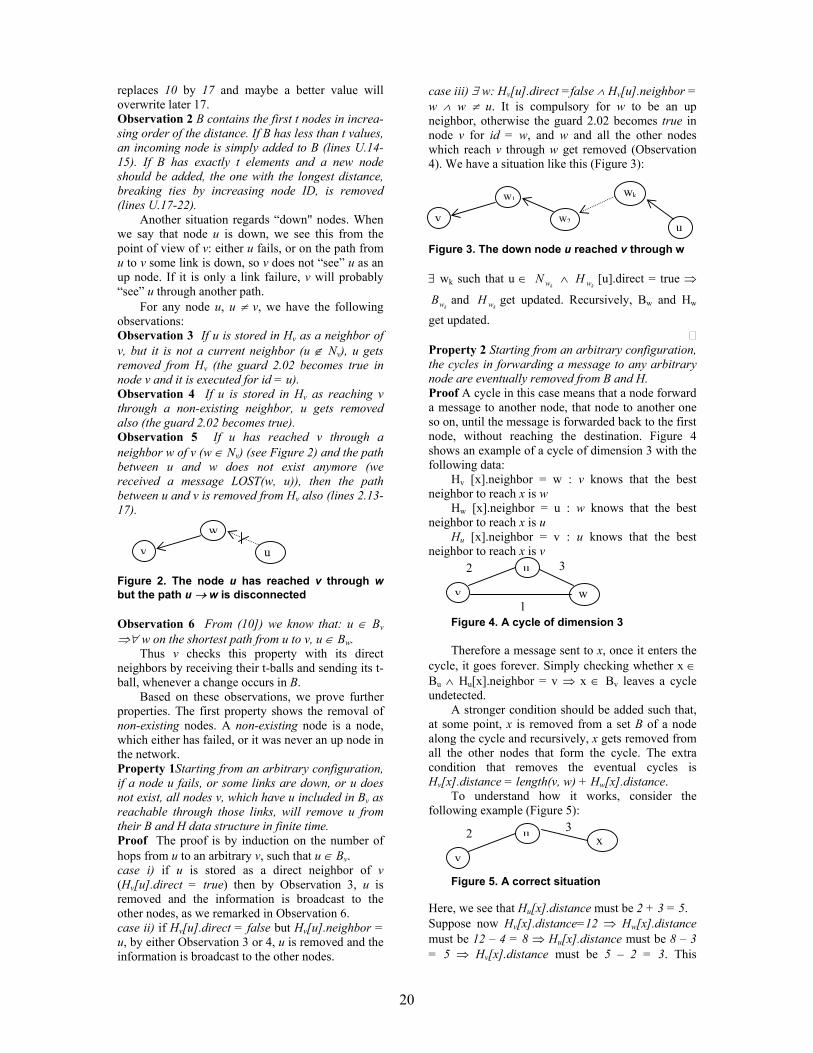
20
replaces 10 by 17 and maybe a better value will overwrite later 17. Observation 2 B contains the first t nodes in increa-sing order of the distance. If B has less than t values, an incoming node is simply added to B (lines U.14-15). If B has exactly t elements and a new node should be added, the one with the longest distance, breaking ties by increasing node ID, is removed (lines U.17-22).
Another situation regards “down" nodes. When we say that node u is down, we see this from the point of view of v: either u fails, or on the path from u to v some link is down, so v does not “see” u as an up node. If it is only a link failure, v will probably “see” u through another path.
For any node u, u ≠ v, we have the following observations: Observation 3 If u is stored in Hv as a neighbor of v, but it is not a current neighbor (u ∉ Nv), u gets removed from Hv (the guard 2.02 becomes true in node v and it is executed for id = u). Observation 4 If u is stored in Hv as reaching v through a non-existing neighbor, u gets removed also (the guard 2.02 becomes true). Observation 5 If u has reached v through a neighbor w of v (w ∈ Nv) (see Figure 2) and the path between u and w does not exist anymore (we received a message LOST(w, u)), then the path between u and v is removed from Hv also (lines 2.13-17).
Figure 2. The node u has reached v through w but the path u → w is disconnected
Observation 6 From (10]) we know that: u ∈ Bv ⇒∀ w on the shortest path from u to v, u ∈ Bw.
Thus v checks this property with its direct neighbors by receiving their t-balls and sending its t-ball, whenever a change occurs in B.
Based on these observations, we prove further properties. The first property shows the removal of non-existing nodes. A non-existing node is a node, which either has failed, or it was never an up node in the network. Property 1Starting from an arbitrary configuration, if a node u fails, or some links are down, or u does not exist, all nodes v, which have u included in Bv as reachable through those links, will remove u from their B and H data structure in finite time. Proof The proof is by induction on the number of hops from u to an arbitrary v, such that u ∈ Bv. case i) if u is stored as a direct neighbor of v (Hv[u].direct = true) then by Observation 3, u is removed and the information is broadcast to the other nodes, as we remarked in Observation 6. case ii) if Hv[u].direct = false but Hv[u].neighbor = u, by either Observation 3 or 4, u is removed and the information is broadcast to the other nodes.
case iii) ∃ w: Hv[u].direct =false ∧ Hv[u].neighbor = w ∧ w ≠ u. It is compulsory for w to be an up neighbor, otherwise the guard 2.02 becomes true in node v for id = w, and w and all the other nodes which reach v through w get removed (Observation 4). We have a situation like this (Figure 3):
Figure 3. The down node u reached v through w
∃ wk such that u ∈ kwN ∧
kwH [u].direct = true ⇒
kwB and kwH get updated. Recursively, Bw and Hw
get updated. Property 2 Starting from an arbitrary configuration, the cycles in forwarding a message to any arbitrary node are eventually removed from B and H. Proof A cycle in this case means that a node forward a message to another node, that node to another one so on, until the message is forwarded back to the first node, without reaching the destination. Figure 4 shows an example of a cycle of dimension 3 with the following data:
Hv [x].neighbor = w : v knows that the best neighbor to reach x is w
Hw [x].neighbor = u : w knows that the best neighbor to reach x is u
Hu [x].neighbor = v : u knows that the best neighbor to reach x is v
Figure 4. A cycle of dimension 3 Therefore a message sent to x, once it enters the
cycle, it goes forever. Simply checking whether x ∈ Bu ∧ Hu[x].neighbor = v ⇒ x ∈ Bv leaves a cycle undetected.
A stronger condition should be added such that, at some point, x is removed from a set B of a node along the cycle and recursively, x gets removed from all the other nodes that form the cycle. The extra condition that removes the eventual cycles is Hv[x].distance = length(v, w) + Hw[x].distance.
To understand how it works, consider the following example (Figure 5):
Figure 5. A correct situation
Here, we see that Hu[x].distance must be 2 + 3 = 5. Suppose now Hv[x].distance=12 ⇒ Hw[x].distance must be 12 – 4 = 8 ⇒ Hu[x].distance must be 8 – 3 = 5 ⇒ Hv[x].distance must be 5 – 2 = 3. This
v
w
u
wk
uv
w1
w2
v
u
w
2 3
1
v
u x 2 3

21
contradicts the initial value of Hv[x].distance=12.
Up to this point we have shown how to remove “bad” nodes from B. Another way to remove elements from B is to set it to ∅. We show that it is possible at most once in every execution of the algorithm SRS in node v. In this way, B will contain, in finite time, the t closest nodes to v, so gradually, the cover will be calculated based on these values, and finally the labeling functions. Lemma 1 Starting from an arbitrary configuration, in any execution, v executes RESTART at most once. Proof Suppose we have executed RESTART. We prove that further actions do not determine another RESTART, by looking at each guard from all the modules that have as action RESTART and we prove that they cannot become enabled again (see Properties 3, 4, and 5). Property 3 After RESTART is executed, in Error_Correction the predicate error remains false (so, its action RESTART is not executed anymore). Proof After RESTART is executed, the data structure B and H are ∅. In the algorithm Calculate_Ball, whenever B adds or removes an element, the same element is added/removed from H. Also, whenever a crash occurs in the network, the node v does not become disconnected, so it has at least one up neighbor. So B does not become ∅ because of Remove_ID executions. Therefore the condition B \ H ≠ ∅ is false from here on. Property 4 Once the macro RESTART is executed, the guard 1.04 of Error_Correction (keeping correct data about the neighbors) remains false. Proof The field direct specifies whether a direct neighbor of v has the shortest path to v through the link between them.
H starts as ∅. Whenever a node is added/updated in H, the value of the field direct of that element is set to false (lines U.08, U.14, U.21, of the macro UPDATE in the algorithm Calculate_Ball).
The only statement that sets the value of the field direct for a node u to true is in the lines 1.06-1.08 of the algorithm Error_Correction. But this is done only if u is neighbor of v and has the direct link as the shortest path (H[u].neighbor = u) and, in this case the field distance is set to the correct value (the value of the length of the link).
The field distance can change when a shorter distance is detected. But at that time, the field direct is set to false automatically (lines U.08 of the macro UPDATE in the algorithm Calculate_Ball).
Taking an example (Figure 6):
Figure 6. A shorter distance through another neighbor
Suppose that initially for the node w stored in
Hv, the values of the fields are: H[w].neighbor=w H[w].distance=5 H[w].direct=true If node v detects a shorter distance to node w through node u, the values are changed in the macros UPDATE (lines U.06-08) to: H[w].neighbor= u H[w].distance = 3 H[w].direct=false Property 5 The guard 2.01 in the algorithm Calculate_Ball (keeping data about unknown nodes, whose DIST messages have not been yet received) remains false. Proof The set Rcvd_IDs keeps all the nodes which have sent information regarding the distance toward the node v. These distances are valid data.
Obviously, we cannot trust the information regarding a node in B whose message has not been yet received. Because of that we execute RESTART when such a node is detected. After RESTART gets executed and B becomes ∅, Rcvd_IDs := ID_v . From here on, Rcvd_IDs will start storing only the IDs of the nodes that have sent messages and maybe have changed the set B. So, B ⊆ Rcvd_ID, so the guard 2.01 remains false. So we have at most one RESTART in every execution. Theorem 1 Starting from an arbitrary configuration, the partial t-ball Bv becomes in finite time the t-ball of node v, Bv(t), required by SRS scheme. The routing table H has the size O((t + ∆v) log(n)). Proof Using the Properties 1 and 2, Lemma 1, and Observation 1.
We know, by Property 1, that B will contain only the up nodes in the network, and with the cycles removed (Property 2). The guards of the algorithm Calculate_Ball updates B in case of new distances or topology changes (Observation 1).
By Lemma 1, once a node starts executing the distributed algorithm, we can have at most one RESTART, which means that B can be reset to ∅ at most once.
H will contain, besides the nodes in B, the direct neighbors of v, which makes a total of at most (t + ∆v) entries (some neighbors can be in B also, and we don't have redundant entries). Each entry has O(log(n)) data bits, so H will have O((t + ∆v)log(n)) bits.
3.2 Self-Stabilization and Time Complexity
We consider d to be the diameter of the network.
In case of network change, d can be modified, so, to be more precise, consider d to be the maximum diameter over all the diameters of the network in
v
u
w
2 1
5

22
different cases which have occurred (in the worst case d = n.)
Because the property of self-stabilization implies that the system will reach a correct state in finite time, we prove the self-stabilization together with an analysis of the time,
We define the state predicate R = Bv = Bv (t), ∀ v ∈ V
indicating that the set B calculated in each node is the defined t-ball Bv (t) (or, the partial t-ball is the t-ball for each node v in a legitimate state). Lemma 2 true converges to R in the network P. Proof By Theorem 1, starting from an arbitrary state, in finite time, for each node v the set Bv = Bv (t).
By Lemma 1, once a node starts executing the distributed algorithm, we can have at most one RESTART, which means that B can be reset to ∅ at most once. So, if we have a RESTART, consider tR the time elapsed until all RESTART gets executed. Time tR depends on the local computation, so we can bound all the tR by a sufficiently large constant c.
And consider t1 time units to received messages from all the other nodes. Time t1 depends on the diameter of the network, because a message can come from at most distance d, and on the time spent by the nodes on the path through which the message reaches v, to process and forwards the message to v. If no RESTART is executed in any node in the network, for each node v ∈ V, in O(d) time units, all the distances are received and the partial t-ball Bv becomes the t-ball Bv(t). So, the set B computed by Calculate_Ball contains the t nearest nodes to v.
Therefore it will take at most tR+t1 = O(c+d) time units for v to calculate its t-ball Bv (t) in the variable B. Theorem 2 The distributed algorithm constructs a SRS scheme in polynomial time. The routing table in node v is of size O((t + ∆v) log(n)) bits and with a total of O(n t log(n)) bits per network. The algorithm stabilizes in O(d+c) time units where c is a sufficiently large constant. Proof By transitivity, using Lemma 2 and Theorem 1. 4. Conclusions
In this paper, we have presented a self-stabilized
routing scheme SRS. As high-speed networks become larger and larger, it is essential to design direct routing schemes, which require a relatively small amount of memory in the nodes for routing purposes. The proposed algorithm is a self-stabilizing routing algorithm for an asynchronous, arbitrary weighted network, and can easily be extended to an unweighted network. It takes O(d+c)
time units to stabilize, where c is a large constant and d is the diameter of the network, and the routing functions use O((t + ∆v) log(n)) bits in each node. It can be used further for different types of routing (hierarchical, compact, interval etc).
Routing algorithms can be used to design efficient solutions to some fundamental problems in distributed computing, such as broadcasting, mutual exclusion, BFS, and DFS. There already exist self-stabilizing solutions to the above problems ([12]). One interesting topic of future research is to find efficient self-stabilizing solutions (more efficient than the existing ones) to the above problems.
5. References [1] Gerard Tel, "Introduction to Distributed Algorithms", 1994, Cambridge University Press [2] M. G. Gouda, "Elements of network protocol design", John Wiley & Sons, Inc , 1998. [3] E. W. Dijkstra, "Self stabilizing systems in spite of distributed control", Communications of the Association of the Computing Machinery, vol 17, 1974, pp. 643-644. [4] B. Awerbuch, A. Bar-Noy, N. Linial, and D. Peleg, "Compact distributed data structures for adaptive routing", Proceedings of the 21th Annual ACM Symposium on Theory of Computing, vol 2, 1989, pp. 230-240. [5] B. Awerbuch , and D. Peleg, "Sparse partition", Proceedings of the 30st Annual IEEE Symposium on Foundations of Computer Science, 1990, pp.503-513 [6] D. Peleg and E. Upfal, "A trade-off between space and efficiency for routing tables", Journal of the ACM, 1989, volume 36, pp. 510-530. [7] E. W. Dijkstra, "Self stabilizing systems in spite of distributed control", Selected Writings of Computing: A Personal Perspective, Springer-Verlag, 1982, pp. 41-46. [8] S. Dolev, "Self-stabilizing routing and related protocols", Journal of Parallel and Distributed Computing, 42(2), 1997, pp. 122-127. [9] T. Masuzawa, "A fault-tolerant and self-stabilizing protocol for the topology problem", Proceedings of the Second Workshop on Self-Stabilizing Systems , 1995, pp. 1.1-1.15. [10] T. Eilam, C. Gavoille, and D. Peleg, "Compact Routing Schemes with low stretch factor", Research Report RR-1195-98, 1998, LaBRI, Universite Bordeaux, Weizmann Institute of Science. [11] A. Arora, and M. G. Gouda, "Closure and convergence: a foundation of fault-tolerant computing", IEEE Transactions on Software Engineering, volume 19, 1993, pp. 1015-1027. [12] Shlomi Dolev, "Self-Stabilization", 2000, The MIT Press.

23
Malicious Internet Use and Homeland Security
Wolfgang W. Bein University of Nevada
Howard R. Hughes College of Engineering, School of Computer Science
Las Vegas, Nevada 89154, USA E-mail: [email protected]
Abstract
The advantages of speed, security and connectivity, which Information Technology brings to businesses and government, are increasingly empowering international terrorist groups. Tools previously only available to national security agencies are increasingly at the disposal of terrorist cells and rogue nations. Powerful encryption methods are now widely available. Anonymizers, which remove the computer's identifying information so that IP addresses are hidden and cookies and scripts are blocked, represent a new advance in Internet technology. These developments raise important questions about the risks of privacy. The Internet offers terrorists an intelligence and reconnaissance tool, giving wide access to logistical data, and - as part of the globalization aspect of the Internet - cultural resources can benefit terrorist activity, teaching customs and mannerisms of the target society.
1. Introduction
There is great enthusiasm about our new digital world; perhaps very much similar to the excitement experienced over nuclear energy throughout society during the middle part of the previous century. Much has been made of the possibility of terrorists using Information Technology for cyber attacks of various kinds, including malicious denial of service attacks through viruses and worms, which could indeed cause societal harm [1]. As much as such cyber warfare does indeed present a clear and present danger, a different dark aspect of cyberspace has received much less attention.
Traditionally, computer scientists have tended to view the quest for Internet privacy as an indisputable goal. Computer and network security tools in tandem with powerful encryption methods are now widely available to the public. Anonymizers represent a new advance in Internet
technology: Such anonymizers are used to remove the computer's identifying information so that IP addresses are hidden and cookies and scripts are blocked. As a result terrorist organizations can operate with the knowledge that their communications are entirely protected.
Many of the tools that were previously only available to legitimate governments are now accessible to terrorist cells and rouge nations. Certainly, since the events of September 11, it has become apparent that Information Technology has the potential to serve as a conduit for terrorist conspiracies.
But beyond the technical there is a profound societal and cultural aspect: The Internet has redefined the meaning of neighborhood, enabling terrorist cells to communicate over long distances, setting up communities of interest, and maintaining terrorist networks that function much like the Internet itself. The digital world gives a new sense of place, where borders play a lesser role; cultural context is weakened, making it easier for foreign terrorist groups to act in their targeted countries. 2. Anonymation and Encryption
Privacy refers to the ability of individuals to protect information about them. Anonymity is the privacy of identity and it can be:
Persistent anonymity (or pseudonymity),
where the user maintains a persistent online persona (“nym”') which is not connected with the user's physical identity (“true name”), or
One-time anonymity, where an online persona lasts for just one use.
The key concept here is that of linkability: With
a nym, one may send a number of messages that are all linked together but cannot be linked to the sender's true name. By using one-time anonymity for each message, none of the messages can be

24
linked to each other or to the user's physical identity.
Some of the more routine uses of persistent anonymity are in message-oriented services, such as email and newsgroup postings. Here, the two major categories are those of sender-anonymity, where the originator of a message wishes to keep his identity private, and of recipient-anonymity, where the recipient desires to enable replies to a persistent persona.
Anonymizers as third party proxies, usually remove identifying information, hide host names and IP addresses, and block cookies and scripts. Such anonymizers are made even more effective by the use of distributed networks of intermediate servers (named Mixes based on David Chaum's Mix-net concept [2]) on the way to the final destination on the Internet. Along these networks powerful encryption methods are employed including the Data Encryption Standard (56-bit key, or higher) or the more recent Advanced Encryption Standard. There is extensive software available using numerous servers all over the globe, suffice it to mention here the open source European JAP project [3]. Many other schemes and software packages are available, e.g., see [4], [5], as well as Figure 1.
Somewhat more exotic, but as readily available, are steganographic programs, which are used to hide data in picture files. Often messages are first encrypted before embedding. Such embedded and encrypted information is extremely hard to find and decrypt; it thus offers ample opportunity for mischievous use.
Figure 1. A Russian site displaying servers which can be used as proxies
3. Socio-Economic and Cultural Factors
Information Technology is most often associated with the vibrant economies of the first world, most notably the economies of North America and Western Europe, and perhaps Japan, and Hong Kong. It is indeed counterintuitive to acknowledge how much the World Wide Web has impacted the infrastructure of third world countries as well as countries with emerging economies.
This trend, however, is illustrated by how fast wireless technologies have leapfrogged outdated phone systems in Eastern Europe. India and Pakistan’s economic progress over the last decade was largely enabled through the emergence of software industries, which relied on fast Internet access. Recently, the country of Afghanistan joined cyberspace by gaining legal and technical control of the "dot-af" domain for Afghan web sites and e-mail addresses.
Thus it comes as no surprise that the Internet and its countless web sites provide a platform for communications and propaganda of radical movements throughout the third world. It well established [6] that Chechnyan radical groups have posted their propaganda on various sites in Russian and English. (See also Figure 2.) Throughout the third world so-called “Internet-cafés” are proliferating, thereby offering ready access that is hard to trace by legitimate intelligence services.
There is a surprising extra dimension in the issue of Information Technology and terror - the dimension of cultural side effects. As recently as twenty years ago, a foreign terrorist group would have found it substantially harder to carry out an operation such as the attacks of September 11. The 19 attackers were not residents of the United States; they were foreign intruders. And yet they were able to blend in with American society quite effectively, able to rent a car, able to lease an apartment, able to successfully get into flight school.
The Internet-generated information abundance of today was very much reserved to intelligence agencies of legitimate governments in pre-Internet times. From airline schedules to event schedules, from city maps to building floor plans, the Internet offers immediate access to detailed information. In fact, only very recently have government agencies and large corporations begun to sift through their web pages, and started the tedious process of deleting or editing sensitive information. Terrorists could take the use of Information Technology one step further, and use digital imaging to carry out surveillance of their targets well in advance and remotely.

25
Figure 2. A pre September 11 jihad propaganda site, cached by the Internet Archive on July 20,
2001
And yet it is not such technical capability alone
that makes the Internet an enabling technology. It is the power of the medium itself. Indeed, the abundance of web sites makes global culture ubiquitous. Foreign attackers can avoid cultural pitfalls of the targeted county, prepare themselves for mannerisms and local customs.
There is loss of a sense of place widely acknowledged in the literature, where the “persistence” and “gravity” of place [7] are replaced by mobility and ‘an unbearable lightness of being.’ Negroponte [8] foresaw this trend about a decade ago (albeit as a positive thing) when he proclaimed that the change from atoms to bits wold be irrevocable and unstoppable.
The kind of homogeneity that the Internet brings to many interactions de-emphasizes local context and culture, and thus rather benefits a foreign attacker. The Internet globalization has been beneficial in many ways, but has become discomforting when viewed in the context of terrorism. 4. Conclusions for Homeland Security
What, then, are the ramifications for Homeland Security? The answers can be categorized roughly as technical, legal, and attitudinal.
In the area of technology and research, the National Research Council [9] developed the following recommendations:
Develop more effective machine-learning
algorithms for data mining, especially
across the entire plane of multi-media file types.
Explore new methods to combine data from multiple sources.
Create better automated tools to handle natural languages.
Improve algorithms for image interpretation, speech recognition, and interpretation of other mixed media, including image and video processing.
Improve tools for reasoning under uncertainty.
Create better tools for data visualization. Project Echelon, which is operated by the
National Security Agency, is a classified reconnaissance project, designed to intercept electronic communications globally. In a recent State Department Report [10] it was pointed out that both the intelligence community leadership, as well as congressional committees have expressed determination to enhance analytical capabilities. Unfortunately, given the advances in cryptography and anonymization, a solution based entirely on technology might not be forthcoming, and in addition to signals intelligence and imagery intelligence, human intelligence will likely have to play a larger role.
In the legal arena, France, and more importantly the United States, have seen the need to regulate export of encryption software. In France, for example, the use of products with a key length of more than 128 bits requires registration with a trusted third party. In the United States export controls were put in place, which have been subsequently loosened to routinely allow export of 56-bit key DES encryption. As discussed in Section 2, some of the restrictions are merely academic by now, as encryption is widely available over the Internet.
Returning to the issue of intelligence, a number of legal obstacles to effective surveillance of terrorist groups were removed in the aftermath of September 11. The USA Patriot Act of 2001 gives law enforcement agencies greater flexibility in obtaining court orders for intercepts when foreign terrorist communication is suspected. It was also designed to facilitate greater sharing of information between law enforcement agencies and intelligence agencies. In fact, the Department of Homeland Security will soon have an Information Analysis and Infrastructure Protection division that will be responsible for analyzing information provided by law enforcement and intelligence agencies. In the future, legislation should accommodate workable solutions in a post cold war world. This might mean:
Public privacy concerns will have to be
balanced with public security concerns.

26
Legitimate Security and Intelligence Agencies have to be given the proper legal tools to use Information Technology effectively.
The real change, however, might be a shift in
societal attitudes towards issues of privacy. Recent events have shown that there is a distinctly dark side to encryption and anonymization. In the past, privacy has been considered a prime objective in Information Technology, and privacy pursuits have been especially strong among Information Technology professional, and most notably among computer scientists. Could it be that our concern might shift to acknowledge the risks of global privacy? 5. References [1] C.P Pfleeger, S.L Pfleeger, Security in Computing, 3rd Edition, Prentice Hall, Upper Saddle River, 2003. [2] D. Chaum. "Untraceable electronic mail return Addresses, and Digital Pseudonyms", Communications of the ACM, 24(2), 1981, pp. 84-88.
[3] JAP Anonymity and Privacy, http://anon.inf.tu-dresden.de/index.html. [4] O. Berthold, H. Federrath, and M Kohntopp, "Anonymity and Unobservability on the Internet". In Proceedings of the 10th Conference on Computers, Freedom and Privacy, ACM, 2000, pp. 57-68. [5] M.J. Freedman and R. Morris, "Tarzan: A Peer-to-Peer Anonymizing Network Layer". In Proceedings of the 9th ACM Conference on Computer and Communications Security, Washington, 2002, pp. 44-54. [6] R. Jacquard, In the Name of Osama Bin Laden, Duke University Press, Durham and London, 2002. [7] R. DeGrandpre, Digitopia, The Look of the New Digital You, AtRandom.com Books, New York, 2001. [8] N. Negroponte, Being Digital, Vintage Books, New York, 1995. [9] National Research Council, Making the Nation Safer: The Role of Science and Technology in Countering Terrorism, The National Academic Press, Washington, 2002. [10] R.A. Best, Jr., Intelligence Issues for Congress, Foreign Affairs, Defense, and Trade Division, Department of State, 2003.

27
Mobile IPv6: Configuration and Trials
Tudor Blaga Technical University
of Cluj-Napoca Tudor.Blaga@ com.utcluj.ro
Virgil Dobrota Technical University
of Cluj-Napoca Virgil.Dobrota@
com.utcluj.ro
Daniel Zinca Technical University
of Cluj-Napoca Daniel.Zinca @
com.utcluj.ro
Mihai Vancea Technical University
of Cluj-Napoca Mihai.Vancea@
com.utcluj.ro
Abstract The paper is focused on Mobile IPv6 recommendations, including draft-ietf-mobileip-ipv6-19 and mainly regarding to Linux Red Hat 8.0. Although Microsoft’s Windows 2000/XP/2003 currently uses the obsolete recommendation draft-ietf-mobileip-ipv6-13, we did select also these operating systems for our trial. The testing scenario did not include from the beginning any wireless equipment. The minimal mobility demonstrator was based on three workstations in a wired network. Note that as soon as the mobile node’s connection is changing, the Mobile IPv6 specific procedures are starting: care-of-address auto-configuration, home registration, and CN notification. We were focused on preliminary evaluation of the following parameters: RTT (Round Trip Time), inter-arrival jitter and cumulative number of packets lost.
1. Introduction
Nowadays mobility support for Internet devices becomes more important, since mobile devices are getting more widespread. Furthermore cellular devices of the 3rd generation will be packet switched devices instead of circuit switched, therefore the need for Mobile IP increases.
Several problems arise, that make roaming with mobile Internet devices difficult. When roaming from one location to another, communication is not possible until the system configures a new IP address, the correct netmask and a new default router. The problem is caused by the routing mechanisms, which are used by IP. IP addresses define a kind of topological relation between the linked computers. The node’s IP address identifies the link on which the node resides, as well as the node itself. If a node moves without changing its IP
address, existing routing protocols are not able to deliver the datagrams to the new location.
Mobility Support in IPv6, called Mobile IPv6 [1] is designed to allow an IPv6 host to leave its home network without changing its address while maintaining all of its present connections and remaining reachable to the rest of the Internet. The mechanism is completely transparent to transport and higher-layer protocols and applications. The aim of this article is to present the main features of Mobile IPv6 and the configuration and testing of the Mobile IPv6 Linux and Windows implementations.
2. Mobility Support in IPv6
When a Mobile Node (MN) changes its point of attachment from one network to another it needs to change its IP address to a topologically correct one, to allow routers to divert datagrams to the new network address. However, at the same time other hosts communicating with MNs, called Correspondent Nodes (CN), need to be able to send packets to the MNs. The aim of Mobile IP is to solve this problem in a way that scales to large numbers of fast moving MNs.
Mobile IPv6 solves the routing problem caused by mobile users. It uses Home Agent (HA), which keeps track of the current care-of address (CoA), of the MN. CoA is the topologically correct address of the MN in the visited network. With this address HA can deliver datagrams that originally were sent to the MN’s home address, by tunneling them to the CoA. When MN moves to another network, it informs the HA of its new CoA by sending a Binding Update (BU) message to the HA. The BU binds the new CoA to the home address of MN for a period of time. The information obtained from BUs is stored by the HA in a special data structure called binding cache.

28
Figure 1. Mobile IPv6 Operation
The Mobile IPv6 operations are the following: Step1: When the MN communicates with a CN,
the CN uses the home address of the MN and the CN’s packets are routed to the home network.
Step2: The packets are then tunneled to the MN
by the HA, while the MN sends datagrams directly to the CN.
Step3: Because the home network is
topologically far from the current location (visited network) of the MN, this is inefficient and this increases the load on the home network. The phenomenon is called Triangle Routing and Mobile IPv6 provides the solution to this, called route optimization. When a MN receives a packet tunneled by its HA it can determine that the original sender of the packet is not aware of the mobility of MN. To inform the CN, MN sends a BU to it.
Step4: This allows the CN to send datagrams
directly to the MN’s CoA, using a routing header. This procedure is illustrated by Figure 1.
If the delays between MN and its HA and CNs
are large, hand-offs may lead to significant packet loss, especially on higher bandwidth links, such as WLANs. To perform smoother hand-offs a MN can also send a BU to its previous router, which will then act as a temporary HA and tunnel datagrams originally sent to the previous CoA to the new CoA of MN.
The signaling in Mobile IPv6 uses destination option headers, which are one type of IPv6 extension headers. They allow piggybacking of signaling information in packets carrying application
data. There are four new types of destination options:
• Home Address option is used to carry the
home address of MN, when it is away from its home network. It is necessary for allowing CN to demultiplex the datagrams it receives.
• Binding Update (BU) option creates, updates and deletes entries in the binding caches of HA and CN. It is used for creating a binding between the source address of the datagram and the home address in the home address option.
• Binding Acknowledgment (BA) option is sent by HA and by CNs in response to a BU to inform MN of the status of the binding update.
• Binding Request (BR) option is sent by CN to request a MN to refresh the binding cache entry for it.
3. Mobility and IPsec
BU and BA change state in the receiving nodes and thus they need to be authenticated. Especially BUs need to be authenticated as they remotely redirect the routing of datagrams to the home address of MN. Mobile IPv6 uses AH (IPsec Authentication Header), for this purpose. IPSec is a protocol designed to secure the TCP/IP protocol suite and it should be a part of every IPv6 implementation. AH is an IPv6 extension header, which protects the integrity of the whole datagram. So it also verifies the identity of the datagram’s sender.

29
Although IPsec provides a means for authenticating the signaling it does not solve the problem of authorization. How can MN prove to a CN that it has the authority to change the routing of its datagrams? This is not a problem between MN and HA as they are likely to already have a Security Association. MN and CN may not have any knowledge of each other at the beginning of their communication and thus the setup of a SA is not trivial. The use of IKE (Internet Key Exchange) together with DNSsec provides a solution, with the assumption that both MN and CN use the same Public Key Infrastructure. 4. Mobile IPv6 for Linux
The package used for testing is MIPL (Mobile IPv6 for Linux). This is an implementation of Mobility Support in IPv6 developed by Helsinki University of Technology. The latest version, mipv6-0.9.5-v2.4.20 implements draft-ietf-mobileip-ipv6-19.txt, although the current draft version is 21, and it works with linux-2.4.20 kernel release.
The package consists of a kernel module, a kernel patch and userspace programs for configuration and installation of the kernel part. 4.1. Installation
The MIPL kernel patch for the 2.4.20 version
should only be applied against fresh kernel tree (or later, provided no changes have been made in the net/ipv6 directory). It is called mipv6-a.b-v2.4.x.patch (where a, respectively b are the major and minor version numbers of MIPL and x is the kernel version sub-level against which the patch was made). MIPL has only been tested on RedHat 8.0 system but should work on any Linux system assuming that you already have a working 2.4.20 kernel and an IPv6 environment.
The first step is to install the kernel patch. Assuming you have a fresh 2.4.20 kernel tree in /usr/src/linux do the following:
cd /usr/src/linux patch -p1 --dry-run < mipv6-a.b-v2.4.x.patch
This does not actually do anything but it displays
errors if any. In case of errors, you should cancel the installation, otherwise you can type:
patch -p1 < mipv6-a.b-v2.4.x.patch Now the kernel tree is ready for configuration.
Run your favorite make *config. Make sure you have at least the following options set:
CONFIG_EXPERIMENTAL=y
CONFIG_SYSCTL=y CONFIG_PROC_FS=y CONFIG_MODULES=y CONFIG_NET=y CONFIG_NETFILTER=y CONFIG_UNIX=y CONFIG_INET=y CONFIG_IPV6=m CONFIG_IPV6_SUBTREES=y CONFIG_IPV6_IPV6_TUNNEL=m CONFIG_IPV6_MOBILITY=m In the package you will find a script,
chkconf_kernel.sh that can be used to check if you have configured the right options.
You may choose 'y' instead of 'm' if you don't want to build Mobile IPv6 as a module. The last configuration option is the newly added Mobility Support. By selecting this it enables Mobile IPv6 Correspondent node operation. You may also select following options:
CONFIG_IPV6_MOBILITY_MN CONFIG_IPV6_MOBILITY_HA CONFIG_IPV6_MOBILITY_DEBUG The first two control whether you want to have
Mobile node or Home agent functionality enabled in addition to Correspondent node. MN and HA can't be enabled at the same time. The last option turns on debugging messages for MIPL. Since MIPL is still work-in-progress you should enable this. With debug messages it is easier to figure out what is happening when something goes wrong.
After you finished the configuration, save changes and exit. Run make dep and compile and install the new kernel and modules. The kernel part is now done.
After the kernel part of MIPL is successfully installed and configured, you still have to compile and install the userspace tools. Run configure to create Makefile and mobile-ip6 for your system. Run make and make install to compile and install userlevel tools, man pages, init scripts and example configuration files. These are mandatory for the module to work correctly. You also need to create the device file for MIPL with mknod /dev/mipv6_dev c 0xf9 0.
4.2. Configuration The Mobile IPv6 configuration file can be found
in /etc/sysconfig/network-mip6.conf. You can select from the following options for configuration:
• FUNCTIONALITY - Should this node act as a
home agent (ha), mobile node (mn) or correspondent node (cn). HA and MN both have CN functionality embedded. Default value: cn.

30
• DEBUGLEVEL - In error situations it may be desired to get more detailed information what is happening. Increase this value to get more messages from the module (default: 0).
• TUNNEL_SITELOCAL - Should unicasts to node's site-local address be tunneled when mobile node is not in its home network (default: yes).
• MIN_TUNNEL_NR - Minimum number of free tunnel devices kept in cache on MN or HA. Must be set to at least 1 for MN and HA. To ensure successful bindings even during high work loads it could be set to a bigger value on the HA.
• MAX_TUNNEL_NR - Maximum number of free tunnel devices kept in cache on MN or HA. Must be set to at least 1 for MN and HA. To improve performance set it higher than MIN_TUNNEL_NR.
• HOMEDEV - Device where home address should be assigned to.
• HOMEADDRESS - Home address for mobile node with prefix length.
HOMEAGENT Home agent's address for mobile node with prefix length.
For run-time configuration and diagnostics we
can use the mipdiag tool. An automatic startup script called mobile-ip6 is included into the package. You can use mobile-ip6 start to start the module by hand and mobile-ip6 stop to unload. This script reads the configuration files and configures module accordingly. Another possibility is to load the module by hand using insmod. You cannot set Home Address nor Home Agent Address with insmod so Mobile Node will be left in a state where it does not know these addresses until given with the mipdiag tool.
If you want to use automatic module startup in RedHat, you must do chkconfig mobile-ip6–level 345 on that will setup all the necessary links. mipdiag, the diagnostic and configuration tool, is used to get statistics and state information and set runtime parameters.
5. Mobile IPv6 for Windows
Currently there is no full support publicly available for Mobile IPv6 in Windows operating systems. Microsoft offers CN support in Windows 2000/XP/2003. Additionally there is a different IPv6 stack for Windows, implemented by I2R (Institute for Infocomm Research), that offers CN support too (based on the recommendations from draft-ietf-mobileip-ipv6-13.txt).
We encountered difficulties during the installation of I2R for Windows 2000/XP so the trials are under progress. We tested the CN support
from Windows 2003 (production release which integrates the Window 2000 IPv6 stack).
Whilst Windows 2000 IPv6 configuration is performed using ipv6 tool, Windows 2003 has integrated it into the network configuration tool, called netsh. This is a shell that offers a set of several commands that resemble the router’s configuration commands. The first step is to enter the network shell with the netsh command. Then you enter the interface ipv6 mode to configure any IPv6 setting:
C:\> netsh netsh> interface ipv6 The set mobility command permits us to
configure the following mobile ipv6 parameters: security, bindingcachelimit and correspondingnode. The first specifies whether the BUs must be authenticated or not (the default values is enabled). We can also specify the number of binding cache entries with the bindingcachelimit parameter and the default value for the number of entries is 32. The last parameter, correspondingnode, specifies if the node will have CN capabilities. The default value for it is disabled. The enabling of CN permits the node to accept binding updates so route optimization can be performed.
netsh interface ipv6> set mobility correspondingnode = enabled netsh interface ipv6> set mobility security = disabled netsh interface ipv6> set mobility bindingcachelimit = 1000
The netsh shell allows us to view the current
setting and status with the following commands:
netsh interface ipv6>show mobility netsh interface ipv6>show bindingcache entries
The first command displays the values of the
three parameters that we have configured and the second one displays the entries from the bindingcache, if there are any. We need to setup the default router for the CN to work properly.
netsh interface ipv6>set route <IPv6 address> /<integer> interface <IPv6 address>
where <IPv6 address> /<integer> is the route we want to set, interface is the name or index of the interface, <IPv6 address> is the gateway address. We can also display the routes that are already set up, with the following command:
netsh interface ipv6>show route

31
6. Trials
The trials performed focused on determining whether the Windows CN support will function with the Mobile IPv6 package from Linux and on a preliminary evaluation of the following parameters: RTT (Round Trip Time), inter-arrival jitter and cumulative number of packets lost. The trials were performed in our laboratory, which is part of CAMAN (Cluj-Napoca Academic Metropolitan Area Network). 6.1. Testbed Architecture
The trial architecture consisted of Fast Ethernet-based wired network with four workstations. The IPv6 router had three interfaces: one acted as Home Network (HN), whilst the others represented the Visited Networks (VN). On the VN interfaces we used radvd for stateless auto-configuration of the hosts connected to that network. You can see below the configuration for interface eth2:
interface eth2
AdvSendAdvert on; prefix 3ffe:a:a:c::/64
AdvOnLink on; AdvAutonomous on; AdvRouterAddr on; ; ;
Figure 2. Trial testbed
The HA has an aggregatable global unicast
address 2001:b30:5000:6::177/64. Below you will find the settings used in the mipl configuration file:
FUNCTIONALITY=ha DEBUGLEVEL=4 TUNNEL_SITELOCAL=yes MIN_TUNNEL_NR=1 MAX_TUNNEL_NR=3 The HA performs double tasks, acting also as
correspondent node within the experiment. CN functionality is implemented together with HA or MN functionalities. The configuration of the MN does not differ from that of the HA. We must specify the home address of the MN, and the address of the HA. For the exact settings used you can see the lines below:
FUNCTIONALITY=mn DEBUGLEVEL=1 HOMEADDRESS=2001:b30:5000:6::170/64 HOMEAGENT=2001:b30:5000:6::177/64 The movement of the MN from the home
network to one of the visited networks, was accomplished by manually unplugging the network connector from one interface to another.
The fourth workstation, which operated under Windows 2003, was used for compatibility testing between the Linux and Windows operating systems, and for evaluating the effects of triangular routing.
For the first trials, the machine was configured to function in the home network of the MN. On the home link, it had an IPv6 address, a default gateway, set up and the CN operation was enabled.

32
The machine was then placed in the third network, and configured as in the first trials, but for addresses used.
Figure 2 presents the entire topology, with the machines placed in all the networks they were tested, although they operated only in one of them at a time.
6.2. Interoperability Testing The testing of the Windows - Linux inter-
operation took place while the MN was at first on the home link an MN that was later moved in one of the visited networks. The Windows-based CN machine sent ICMPv6 echo request messages to the home address of the MN. The results showed that for a brief period of time the connection between the two machines was lost (the period of time that the MN was not connected to any network), but shortly after that the connection was reestablished.
To find out if the CN has received the binding update message, from the MN, we used the netsh mobility command show bindingcache. We noticed that there was no entry in the cache, so we repeated the test, but this time we disabled the security option. There were again no entries in the binding cache.
In order to find out what the problem was, we used the Ethereal tool to capture all the traffic from the home link. After analyzing the packets, we discovered that the problem is caused by the different specifications of the two IETF recommendations. The Windows 2003 CN support is based on the 13th version, while the Linux Mobile IPv6 implementation is designed on the 19th version specifications. Furthermore the 19th recommendation specifies that, Home Test Init, Home Test, Care-of Test Init and Care-of Test messages are used to initiate the return routing procedure from the mobile node to the correspondent node. This ensures authorization of subsequent Binding Updates. The results of the interoperability testing show that the two machines can communicate only with a packet tunneling performed by the HA, but this causes significant loss of performance.
6.3. Preliminary Evaluations
Our results focus mainly on RTT evaluation, while inter-arrival jitter and cumulative number of packets lost evaluations are in progress. The results in this paper were taken from the average RTT values, obtained by ping6 utility. Note that it displays the maximum, average and minimum RTT.
The influence of the packet size was studied too, varying from the default 56 bytes up to 50,000 bytes.
We conducted several trials and then we compared the results. The first thing we evaluated was the operation of the router from our laboratory compared to the one from the Communication Center. The following trial presents the differences between the MN operation on the home link and its operation in a visited network. To discover the delays cause by the Mobile IPv6 extensions we analyzed the times recorded when the MN operates in the visited network and when a computer is setup in one of the VN’s. Our last measurements try to evaluate the effects caused by the lack of route optimization, the packets from the CN are tunneled to the MN by the HA.
Figure 3 presents the results provided by the testing of Router 1 (used in all of our trials) and Router 2 (i.e. IPv6 router from the Communication Center). The packet sizes varied from 56 up to 2048 bytes. As we can observe, the Router 1’s performance is better than that of Router 2. The time it takes the router to forward a packet from one interface, is to be taken in consideration, in all of the following trials. Note that in the first scenario a Fast Ethernet hub connected all the hosts.
The following trial focuses on determining the differences between the RTT values for Mobile IPv6 and IPv6. This trial consisted of two parts. In the first part we determined the times between the HA and the MN, while the MN was in a visited network. The next step, was to configure in one of the visited networks a machine, that will act as an IPv6 node on that link. The RTT values were read once more. The two sets of values and their difference can be observed in figure 4. Although the time difference is fairly small, we must notice that RTT is bigger with 10% in average for Mobile IPv6 than for IPv6.
The time gap is caused by the IPv6 extensions used, by the time it takes the nodes to process the extra headers, like the routing header or the home address option.
The effects of packet tunneling are evaluated in the 4th series of trials. The RTT between the MN and the CN was determined in three situations. The first measurement was made when the CN was located in the 3rd test network. Then we configured the CN to function on the home link of the MN and we determined the RTT again. The final situation relied on the HA/CN embedded functionality offered by the MIPL implementation. While the last test used the Linux package the first two used the Windows 2003 support.

33
Figure 3. Router’s performance
Figure 4. Mobile IPv6 – IPv6 comparison

34
Figure 5. Packet tunneling effects
As we noticed when we tested the Linux-
Windows interoperability, it is not possible for the CN to use the route optimization mechanism, so the packets addressed to the MN will be tunneled by the HA.
Figure 5 presents the results we have obtained, and also the differences between the packet tunneling operation mode and the routing header mechanism.
The results show that for small packets, up to 2048 bytes, the RTT for the packet tunneling is about 20% bigger than for routing header use. For bigger datagrams the value decreases, for 50000 bytes it reaches 4%.
The great RTT values recorded, when the CN was in the third network, demonstrate the necessity of route optimization. The times are over 100% greater than when routing header is used.
In all our trials the cumulative number packets loss was zero. 7. Conclusions and further work
The MIPL implementation is fully functional, as our trials have showed, but it is designed based on draft-ietf-mobileip-ipv6-19.txt although the current recommendation is draft-ietf-mobileip-ipv6-21.txt.
The Windows 2003 CN support does not function with the Linux package, because of the major differences between draft-ietf-mobileip-ipv6-13.txt and draft-ietf-
mobileip-ipv6-19.txt. For a complete Windows-based Mobile IPv6 trial only, we have to wait until the proper recommendation will be released.
The preliminary RTT evaluation shows the importance of IPv6-enabled routers and the effects of route optimization. Several measurements related to the cumulative number of packet loss and inter-arrival jitter are under progress. Finally, the use of wireless devices is required for a complete evaluation of Mobile IPv6 operation.
8. References [1] Johnson, D. and C. Perkins, Mobility Support in IPv6. draft-ietf-mobileip-ipv6-21.txt. 26 February 2003. [2] Johnson, D. and C. Perkins, Mobility Support in IPv6. draft-ietf-mobileip-ipv6-19.txt. 29 Oct 2002. [3] Johnson, D. and C. Perkins, Mobility Support in IPv6. draft-ietf-mobileip-ipv6-13.txt. 17 Nov. 2000. [4] Johnson, D. and C. Perkins, Route Optimization in Mobile IP. draft-ietf-mobileip-optim-11.txt. 6 September 2001. [5] Dobrota, V., Digital Networks in Telecommunications. Vol. III: OSI and TCP/IP, Second Edition, Mediamira Science Publishers, Cluj-Napoca, 2003 (in Romanian) [6] Nikander, P. and C. Perkins, Binding Authentication Key Establishment Protocol for Mobile IPv6. Draft-perkins-bake-01.txt. 2 July 2001.
35
An Open-Source Proposal for Educational Web Site Developement
Mihaela Brut Faculty of Computer Science, “A.I.Cuza” University of Iaşi, Romania
[email protected] – http://www.infoiasi.ro/~mihaela
Abstract
In this paper, we propose an open-source and platform-independent solution based on XML (Extensible Markup Language) family for deployment activities of the pedagogical materials available on an educational Web site, giving to all members of the academic institution the possibility of co-operating for this purpose. This proposal refers to a centralized management of a flexible tool able to automatically generate complex and attractive Web presentations, either in SMIL (Synchronized Multimedia Integration Language) or HTML+TIME language, for using as course tutorials or in different student teaching and testing activities. For the design refinement of the Web site, we take into account a solution for building a meta-interface based on XUL (Extensible User-interface Language). As well, the security access system is discussed. By thus, the work of the site manager is easier, any member of the institution could valorize the personal work and ideas, having access to a friendly user-interface, and the aspect of the Web site, still remaining unitary, is permanently enhanced.
1. Introduction
The use of the World Wide Web modern technologies in the teaching process has increase enormous in the last years, becoming a current reality. In 2001, over 98 percents of American and Canadian schools were connected to Internet, and in Romania actually there are many educational programs regarding the Web connected computers endowment. In all kinds of schools, the Internet became an object to study and a bibliographical / imagistic source equally in teaching and in home works preparation. The actual society invests enormous in the IT training of all specialties and kinds of instructors and tutors [9].
Actually, there are many Web educational sites available, having different owners: virtual universities, academic institutions having a department of distance education, cultural or academic foundations, and different companies. The
structure of a Web educational site is very complex [17], involving a public section – with an informative character –, a section destined to students, one for instructors and the possibility of administrative overall control. It is very important the modality of e storing and managing the teaching materials, information about students, results of tests, etc. The teaching stuff suffers permanent changes, every instructor having his personal style in preparing materials and in exposing information. However, the general image of the site must remain unitary. An important particularity which must be considered by the manager of an educational site is the great mobility of the teaching stuff and of the students.
We propose an open-source and platform-independent solution based on XML (Extensible Markup Language) family for deployment activities of the pedagogical materials available on an educational Web site. The main goal of our proposal is to facilitate the involving in the site development of all persons who participate to educational process, for creating pedagogical materials, as well as for refining the site design. We also provide a solution for organizing the adjacent and the internal information of the site, taking into account the security access to the information.
Our proposal offers a solution for creating teaching materials conceived as Web presentations and facilitates the implementation of any site design idea, providing a friendly user-interface experience for all actors of the educational process who want to contribute at the site development, without the need of any knowledge of Web programming languages. By thus, it shall be obtained a unitary and attractive profile of the site, the work of the site manager shall be easier, and the communication between students, instructors and administrative stuff shall be notably improved. XHTML, SMIL, HTML+TIME, XUL, XML and free-available script languages (Perl, JavaScript, PHP) could be used for this implementation.

36
2.Creating Multimedia Web Presentations 2.1 Short presentation of SMIL
SMIL (Synchronized Multimedia Integration Language) is an XML-based language [12] developed since 1998 by the Web Consortium in order to facilitate the creation of interactive multimedia presentations. SMIL enables authors to describe the temporal behavior of a multimedia presentation, associate hyperlinks with media objects or describe the layout of the presentation on a screen. A presentation is composed from several components, each including different media types, such as audio, video, image or text, and could being executed sequential, parallel or in a combined manner. Control buttons such as stop, fast-forward and rewind allow the user to interrupt the presentation and to move forwards or backwards to another point in the presentation.
SMIL 2.0 – the actual version of the language – is defined as a set of reusable markup (annotation) modules. This allows reuse of SMIL syntax and semantics in other XML-based languages, in particular inside those that need to represent timing and synchronization [1]. For example, SMIL 2.0 components are used for integrating timing into XHTML [13] and into SVG [2]. There are special players for SMIL developed by different companies, such as the RealOne of RealNetworks or Oratrix’s GRiNS player and editor. The general trend is to incorporate support for SMIL even in the Web browsers: Internet Explorer 5.5 and up plays XHTML+SMIL [10], Apple’s QuickTime version 4.1 or later supports SMIL 1.0 and Adobe's SVG Viewer supports SMIL animation in SVG [20].
Example. The SMIL multimedia presentations are easy to be written and do not require sophisticated authoring tools, because there are simply text XML-based files. As an example, a short SMIL document is listed below. The presentation will split the computer screen into two regions, a movie (in the MPEG format) and a text file being displayed in parallel for 40 seconds, each in a specific region, while in the background a sound file is playing:
<!DOCTYPE smil PUBLIC
"-//W3C//DTD SMIL 2.0//EN" "http://www.w3.org/TR/REC-smil/SMIL20.dtd"> <smil xmlns= "http://www.w3.org/2001/SMIL20/Language"> <head> <layout type="smil-basic-layout"> <!-- a region that will display the video document --> <region id="VideoPlace" top="25" left="125" width="875" height="650" /> <!-- a region that will display the text content -->
<region id="TextPlace" top="555" left="225" width="875" height="200" /> </layout> </head> <body> <par> <!-- the multimedia content will be rendered in parallel --> <audio src="presentation1.rm" dur="20s" /> <video region="VideoPlace" src="videos/course1.mpg" dur="10s" /> <text region="TextPlace" src="docs/course.php" dur="40s" /> </par> </body> </smil> 2.2 The HTML+TIME alternative
HTML+TIME (Timed Interactive Multimedia Extensions for HTML) language was developed by the Microsoft, Compaq and Macromedia companies for facilitating to the authors to add time-based presentation effects to Web pages than using an external, XML-based document. Thus, HTML+TIME extend HTML by adding a set of time-based attributes to its entire existing tag set [15].
For example, an identical set of attributes could be applied to a paragraph, an unordered list and a table, which shall be displayed in parallel each for 5 seconds, but starting at different moments:
<!DOCTYPE HTML PUBLIC "-//W3C//DTD HTML 4.01 Transitional//EN"> <html> <head> <!-- using CSS mechanisms to include a temporal behavior --> <style type="text/css"> .time behavior: url(#default#time2); </style> </head> <body> <div class="time" repeatCount="5" dur="10" timeContainer="par"> <p class="time" begin="0" dur="5"> A line of text shall appear first.</p> <ul class="time" begin="2" dur="5"> <li>After 2 seconds, an unordered list</li> <li>…having 2 items</li> </ul> <table class="time" begin="4" dur="5" cols="2" rows="1" border="1"> <tr> <td>A table with 2 columns</td> <td>appears after 2 more seconds </td> </tr> </table> </div>
37
</body> </html>
Offering similar capabilities like SMIL, the HTML+TIME language could be used for creating on-line tutorials in the form of Web presentations, which could be linked subsequent to a namely page in the educational site. The XML parentage of SMIL language is an important prerogative which to be taken into account.
Moreover, a SMIL presentation can play only in a region of the site, having no interaction with the rest of the Web page. In contrast, using HTML+TIME, through the HTML DOM (Document Object Model), all the elements in the page can interact with each other, participating in the presentation. For our organizational model, is strongly recommended for the presentations to be independent with the rest of the educational site, so SMIL is the suited solution. Even Dave Raggett, one of the HTML developers, approve that SMIL is great for timing media clips, e.g. presenting an HTML document along with an audio commentary and accompanying images [14].
The main goal of our system’s structure is to offer to each member of educational stuff which contributes to the site development the possibility of being the only manager and responsible for all information and multimedia documents inside his/her presentations or other types of Web pages, making changes whenever wants. For this purpose, the materials of each author shall be placed in a special subdirectory in the location destined to a certain course, the author being the single person having modifying rights for that subdirectory.
3. Using XUL to Build a Web Meta-Interface
It is possible that many members of the academic institution to be familiarized or attracted by the facilities of a visual interface editor. Their abilities could be used in the context of our open-source and platform-independent proposal through the mediation of XUL (Extensible User-interface Language), an XML-based language defined as a part of the Mozilla project [11; 8].
XUL provides various types of widgets used to build complex graphical interfaces that can be a valuable advantage in designing and implementing an e-learning Web environment. These widgets are very similar with the current approaches used in graphical user interface development environments such as Borland Delphi or Kylix, Glade, Qt Designer or Microsoft Visual Studio .NET. Any member familiarized with such visual environment could use a XUL meta-interface both to provide certain functionality or a design extension for each multimedia presentation, and to create a new type of pedagogical material.
Because XUL is a platform-neutral language, the Web graphical user interfaces designed in XUL shall have the same look and behavior on different operating systems or graphical architectures (for example, standard Motif architecture from XWindow System).
A short example of an XUL interface follows [6]: <?xml version="1.0" ?> <!-- a window with a tabbed dialog --> <window title="XUL – Simple Example" xmlns= "http://www.mozilla.org/keymaster/ gatekeeper/there.is.only.xul"> <tabcontrol> <tabbox value="Documents" /> <tabbox value="Images" /> <tabbox value="Videos" /> </tabcontrol> </window>
The XUL documents have no reference or direction as to how it should be displayed. In Mozilla/Netscape browser, this is the task of the Gecko internal engine, which takes XUL constructs and adds a “skin” to the XUL skeleton to proper display the elements’ interface in a platform-independent way. By using XSL (Extensible Stylesheet Language) stylesheets [21; 8], it is straightforward to transform XUL elements into XHTML or SMIL pages, according to the Web designer needs. This property shall take into account by our proposal in order to adopt a flexible solution to easily build effective educational Web sites, using exclusively open-source technologies.
4. Developing The Educational Web Site
The process of developing and maintaining an educational Web site is a very complex one, not only requesting the appropriate hardware and software support, but implying a great number of specialists: project manager, system architect, creative lead, security architect, database developer, component developer, UI (user interface) developer, graphic artists, HCI (Human-Computer Interaction) engineer, and even others [7]. In a past article [3], we proposed a model for the management of the information resources inside an academic institution, especially a faculty of computer science, that use and develop in the same time different related educational projects, taking into account two aspects of the organization approach: the outlook of the data formalism for the information system and the pursuit of a set of directions for facilitating and stimulating the collaborative communication between all project teams members.

38
4.1. The Information Organization System
Inside the intranet of the academic institution, the person(s) who has/have an overall information control is the network administrator(s). His role is to manage distributed information about both users (accounts, rights etc.) and information resources of the institution’s computer systems – physical resources (e.g. storage systems, printers etc.) and logical resources (i.e. databases, processes of the operating systems, applications and others). These resources need to be allocated to different users by using various permissions policies: individual access, group access, access for the intranet’s domain, or public access.
The organization of all information regarding the Web site of the academic institution is the task of the site manager. Our suggestion made in another past article [4] is to organize on the site server different directories for each academic year, having corresponding subdirectories for every module, sub module, discipline, instructor etc., in these being stored all the materials about the courses and students. For each atomic organizational unit shall be create a group of users having different rights. Every student shall obtain from the network(s) administrator a user name and a password in the moment of admission, which shall be removed at the end of the studies. As well, the instructors and the administrative stuff of academic institution detain such accounts. In order to control the information access, the site manager could appeal to the modules described in the first mentioned article [3]. Hereby, a student shall be authenticated by the WebIdent module, while WebRights module shall assigned the rights for having access to all materials adjacent to the followed courses, by enrolling the respective student in the proper groups of users.
An instructor should access by a unique user name and the right password the materials from all modules he was involved in teaching activities, having modifying rights only at the materials managed by him. A person from administrative stuff shall access for modifying only the general information from the site. The casual visitors should access for reading only the public section of the site.
4.2. The Web Presentations Management System
The proper persons to create and manage the courses tutorials, tests and other teaching materials placed on the educational site are even the authors of their content. Because the diversity of this persons specialties, we exposed in [5] a solution to facilitate the automatically generation of the teaching materials as Web presentations.
The site manager could conceive – in XHTML [13], for example, – a Web form by which to ask for all information necessary to build a course tutorial in
the form of a SMIL presentation: text, audio, video, graphic streams of data, associating with the action of this form a CGI script which to generate the desired SMIL presentation file. For example, a course tutorial could be progressive presented in some slides by: its theme, summary, the principal goal, a general description of the each main subject, and a detailed presentation of each topic, an example in the closing section of every sub-chapter, some conclusions and bibliographical recommendations in the end. The CGI script have to take over the content of each field of the form in a variable, creating a file with each textual information, and then to generate the markups (tags) of the SMIL file, specifying the names of all existing files as values for animation and temporization attributes. Accessing such a form, any member of the educational stuff could easy build a SMIL presentation, storing it temporary on the computer from his/her office.
In order to integrate the presentation into the educational site, the respective member could use another Web form – provided by the site manager, too – where to fill in the complete information about the course: academic year, module, discipline, group of instructors etc. This information is transformed by the script into an XML document. This file is being automatically sent to the site manager, who could affiliate this file to the general site of the company, by associating a hyperlink in the site with the SMIL file. Also, the script has to realize the upload action for storing the SMIL presentation in the proper subdirectory, corresponding to the respective academic year, module, discipline, etc. We choose XML because this document type could be processed regarding formal rules defined by a Document Type Definition (DTD) or an XML schema [21]. By this way, on the server, in the special location of the general site files shall be stored only the corresponding XML document, not entire the presentation, which shall be definitively stored in its correspondent subdirectory. The structure of the XML document could be, for example: <presentation type=”tutorial”> <!-- tutorial stored in /test/exercise --> <item type=”text/smil”>
<name>JavaLesson1</name> <description>
Swing details … </description> <desc href=”demo1.smil”> ... </desc> <!-- the location shall be automatically completed by the script-->
</item> </presentation>
Because a SMIL presentation constitute an attractive manner for presenting a personal idea or the results of the work, a set of similar Web forms

39
could be put at the disposal of all academic institution members to facilitate the professional communication between them. By this way, SMIL presentations could become a familiar dialect for different specialty persons, without being necessary the knowledge of SMIL language or others programming matters.
Also, the site manager could conceive Web forms for generating other types of teaching material: tests, exercises, etc. For each type, the educational stuff could give ideas relative to different kinds of such material, to be taken into account by the site manager. For example, the generated tests could be one/multiple answer, with equal/different score assigned with each question, etc. The scripts which process the corresponding Web form shall manage the manner of storage the answers given by the students, etc.
We give below the image capture of one slide of a Web presentation built in HTML+TIME.
4.3. Refining the Design with XUL
For the institution members familiarized with the facilities of an visual interface editor, the site manager could conceive an XUL meta-interface: an Web interface built in XUL which put at the user disposal the entire set of widgets under a graphical form. Each widget could be included inside a XUL document by associating the proper action to the “drag and drop” or/and to the “double click” event(s). By this way, any user could easy build graphical interfaces for the teaching materials who want to include into the site. For the purpose of an unitary site style, each new XUL document create with this meta-interface could already contains some identification elements, such as the institution coat of arms, the current university year, etc.
Using this XUL meta-interface, the users could conceive themselves the structure of the teaching material, not having to follow the presentation route imposed by the Web form discussed in the previous section. Following the opportunities provided by a
PowerPoint-like application, the XUL meta-interface could give the possibility to insert a new “slide” in the XUL document, as well as the resulted XUL document being in fact a Web presentation.
Moreover, for each slide of the generated XUL presentation, the site manager could put at the user disposal – by the XUL meta-interface menu – a set of slide design layouts, similar to those from PowerPoint, containing text, bulleted lists, tables, images, graphics, etc. By thus, a Web presentation shall have a professional aspect, the variation of design eliminating the possibility of a boring or ineffective interface.
Because presently only a few clients (i.e. Mozilla or Netscape browsers) may directly support XUL, we do not intend to post on the site the XUL presentation. The site manager could conceive different “proxy” programs in order to automatically transform XUL documents into SMIL or XHTML+TIME multimedia presentations. In fact, XUL documents can act as containers [6] for multimedia-rich synchronized elements annotated in other XML dialects such as SMIL, XHTML+TIME or SVG languages.
By this way, the user can build a personalized Web presentation in XUL, using a XUL meta-interface, but he/she obtain as result the corresponding SMIL or XHTML+TIME multimedia presentations, which shall be managed as was mentioned above. If the structure and the design of new teaching material is new and could be helpful to the others members of the academic institution, its layout could be saved through the XUL Web meta-interface.
The XUL meta-interface could give to the user the possibility of “opening” a SMIL or XHTML+TIME document, that it means it shall be generated a new XUL document which to incorporate the native SMIL / XHTML+TIME tags. By this way, a user could modify the content or the design of an existing SMIL presentation through a friendlier graphical user interface. The bidirectional transformations in or from XUL documents could be processed inside the XUL meta-interface by the means of XSL (Extensible Stylesheet Language) stylesheets. 5. Conclusions and Further Work
Our proposal for developing the educational web
sites tries to cover many problems that we consider important: the platform-independence and the open-source character of the solution, the discharging the work of the site manager, the automatically updating of the site, and – not in the last – the participation of all members of the academic institution to the site development. Having complete rights to the personal created teaching materials, any member is the single responsible for these. A Web XUL meta-interface can give him/her the possibility
40
of modifying them from anywhere and anytime, as well as the opportunity of creating new materials and layouts, within a friendlier graphical user-interface experience. The teaching materials are created as XUL documents and generated as SMIL Web presentations.
We are considering SMIL as the appropriate language for the synchronization and integration of Web-based multimedia sources, making the development and management of multimedia Web pages a more streamlined, efficient process [14]. The XML-based property of SMIL language is one important prerogative, beyond its capacity of making the message in the transmission clearer or more attractive.
A future direction in our research shall regard the possibilities for the academic institution members to modify their presentations from any place on the globe including via WAP, and to store the educational resources files on multiple computers, in a complex distributed manner. Also, taking into account the great amplitude and the permanent development of the distance education phenomenon [19], we shall try to design a set of Web agents which to gather useful information from similar educational Web sites or from reference bibliographical resources.
References
[1] J. L. Beckham, G. Fabbrizio, N. Klarlund, Towards SMIL as a Foundation for Multimodal, Multimedia Applications, W3C’s Multimodal Interaction Activity Group, 2002: http://www.w3.org/2002/mmi/2002/smil-rexx.pdf [2] J. Bowler, Scalable Vector Graphics (SVG) 1.0 Specification, W3C Recommendation, Boston, Sept. 2001: http://www.w3.org/TR/SVG [3] M. Brut, S. Buraga, S. Tanasă, A High-Level Model for Management of the Information Resources of an Academic Organization, QTICT'02, CD-ROM Proceedings, Galati, Romania, Oct. 2002 [4] M. Brut, A Proposal For The Management Of Educational Web Sites, In: Scientific Annals of “Dunărea de Jos” University of Galaţi, 2003 (to appear) [5] M. Brut, Multimedia Human-Computer Interactions, in Digital Economy – the Proceedings of the Sixth International Conference on Economic Informatics, INFOREC Printing House, Bucharest, Romania, 2003; [6] Buraga, S., An XML-based Approach in Designing and Building of Web User-Interfaces, in Digital Economy – the Proceedings of the Sixth International Conference on Economic Informatics, INFOREC Printing House, Bucharest, Romania, 2003; [7] S. Buraga, Web Sites Design, Polirom, Iasi, 2002. In Romanian
[8] S. Buraga, Web Technologies, Matrix Rom. Bucharest, 2001. In Romanian [9] M. Jalobeanu, WWW in education, Casa Corpului Didactic, Cluj, 2001. In Romanian [10] D. Newman, A. Patterson, P. Schmitz, XHTML+SMIL Profile, W3C Notes, Boston, January 2002: http://www.w3.org/TR/XHTMLplusSMIL/ [11] Oeschger, I, XUL Programmer's Reference Manual, Mozilla.Org, 2000: http://www.mozilla.org/xpfe/Xulref.zip [12] J. van Ossenbruggen, L. Rutledge, et al., Synchronized Multimedia Integration Language (SMIL 2.0) Specification, Aug. 2001: http://www.w3.org/TR/smil20/ [13] S. Pemberton et al., XHTML 1.0 - The Extensible HyperText Markup Language, W3C Recommendation, Boston, Jan-Aug 2002: http://www.w3.org/TR/xhtml1/ [14] L. Rein, Is HTML+Time Out-of-Sync With SMIL?, O'Reilly & Associates, October, 1998: http://www.xml.com/pub/a/98/10/htmltime.html [15] P. Schmitz, Jin Yu, P. Santangeli et al., Timed Interactive Multimedia Extensions for HTML (HTML+TIME). Extending SMIL into the Web Browser, Sept., 1998: http://www.w3.org/TR/NOTE-HTMLplusTIME [16] A. Tanenbaum, Modern Operating Systems. Addison-Wesley, Reading MA, 2001 [17] * * *, Distance Education Clearinghouse: http://www.uwex.edu/disted/siteindex.html [18] * * *, Distance Education at a Glance: http://www.uidaho.edu/eo/distglan.html [19] * * *, Weblearning Resources: http://www.knowledgeability.biz/weblearning/ [20] * * *, W3C, Synchronized Multimedia: http://www.w3.org/AudioVideo/ [21] * * *, World Wide Consortium's Technical Reports, Boston, 2003: http://www.w3.org/TR/

41
An XML-based Semantic Description of Distributed File Systems
Sabin-Corneliu Buraga Faculty of Computer Science, “A.I.Cuza” University of Iaşi, Romania
[email protected] – http://www.infoiasi.ro/~busaco
Abstract
The actual modern operating systems must incorporate a variety of Internet services, especially World-Wide Web facilities to access distributed resources using file systems mechanisms. In this paper we present a high-level model describing a general distributed file system. The proposed description is based on Resource Description Framework (RDF) recommendation of the World-Wide Web Consortium – a general purpose XML-based technology that enables the semantic description of resources on the Web. To represent the RDF statements about various file characteristics, an XML-based language – Extensible File Properties Markup Language (XFiles) – is presented.
1. Introduction
A distributed system is a collection of loosely coupled computers interconnected by a communication network. From the point of view of a specific computer in a distributed system, the rest of the machines (also known as hosts) and their respective resources are remote, whereas its own resources are local [10, 12].
Important part of a distributed operating system, a file system provides file services to clients (other hosts of the network). A client interface for a file service is formed by a set of primitives, called file operations, such as open a file, remove a file, read from a file, write to a file, and so on.
A distributed file system [7] is a file system whose clients, servers, and storage devices are dispersed among the interconnected computers of a distributed system.
In practice, the concrete configuration and implementation of a distributed file system may vary and it is difficult to determine the best implementation. A distributed file system can be implemented as part of a distributed operating system or by a software layer whose primary function is to manage the communication between conventional operating systems and file systems. Some examples of distributed file systems are Sun's
Network File System (NFS) build on Remote Procedure Call mechanism [5, 12] – broadly used on Unix-like systems –, Prospero – an Internet-compatible virtual system model based on Uniform Resource Identifiers (URIs) –, or Coda – an experimental file system developed at Carnegie Mellon University [7, 12].
The paper proposes a high-level description of a virtual (distributed) file system using Resource Description Framework (RDF) [3, 8], a model for processing metadata. RDF provides interoperability between applications that exchange machine-understandable information on the World-Wide Web. The RDF is intended to be used to capture and express the conceptual structure of information offered in the Web, in order to build the infrastructure for Berners-Lee's Semantic Web [1].
One of the major goals of RDF is to make it possible to specify semantics for data based on Extensible Markup Language (XML) [2, 3, 15] in a standardized, platform-independent, and object-oriented manner. RDF can be used in resource discovery, in cataloging activities, by intelligent software agents, in content rating, in describing collections of data, etc.
The proposed RDF model can be applied for a particular distributed file system. To illustrate some specific issues we choose the Unix file system structure. For expressing various file properties, we present an XML-based language called Extensible File Properties Markup Language (XFiles language) [4]. The elements of XFiles language will be used to specify RDF statements about the components of a distributed file system or about the relationship between these components.
Also, the proposed RDF description can be used to formulate high-level assertions about main characteristics of a distributed file system or relations between Web resources, in a standardized and platform- and implementation-independent manner.
2. File Systems
Most visible aspect of an operating system, the file system consists of two distinct parts: the collection of the actual files, each containing related

42
information, and the directory structure, which provides information about all the files in the system. All modern operating systems have an acyclic graph directory scheme of logical file storage [10, 12].
We can view a file like an abstract data type. To manipulate this data type we can define a minimal set of file operations (primitives):
open() is used to open a file. This primitive returns a special value called handler to be used in other file operations. h = open (f), f ∈ FileNames, h ∈ Handlers
close() is used to close a file and to free the associated file handler. close (h), h ∈ Handlers
seek() is used to set the file pointer for the next input/output operation; this primitive gives the possibility to access the file in a sequential or direct manner. seek (h, p), h ∈ Handlers, p ∈ Z
read() is used to read from a file specific data into a memory buffer (variable). read (h, m), h ∈ Handlers, m ∈ Memory
write() is used to write to a file specific data stored into a memory buffer (variable). write (h, m), h ∈ Handlers, m ∈ Memory
Formally, the Handlers, FileNames, Memory sets
are abstract data types. In practice, Handlers ⊆ N, FilesNames ⊆ Chars+ and Memory ⊆ N, where Chars is a set of valid filename characters (subset of ASCII or Unicode character codes).
In reality, there are many other useful file primitives [5, 11]. These primitives are commonly implemented by the operating system kernel [9].
Each particular file system presents same interface with the programmer (or user). Each file is represented like an abstract data structure called vnode (virtual information node). The vnodes are data structures used by a virtual file system [9, 11]. For each particular file system – e.g. Linux ext2, ext3 and proc file systems, IBM's High Performance File System (HPFS), or Microsoft's Windows NT File System (NTFS) file systems – or file type, we can derive – in the object-oriented methodology sense – from the vnode class a specialized class to specify particular primitives (methods) for dealing with that file system. In the vnode class, each operation can be considered as pure virtual.
For uniformity, the vnode class will be used to represent pipes, devices, pseudo-devices, processes or sockets, in the same manner. Each special device or communication line is viewed like a file and same primitives can be used to access particular information on that file [9].
In Unix (particularly Linux), this model is implemented by means of a special data structure called inode-operations [11, 12]. Each system resource is considered to be a file and different
supported and mounted file systems will be managed by same primitives. For Linux ext2 file system and for other Unix file systems, the data structure used to manage file information is called i-node.
For distributed file systems, we must consider the naming and the transparency of files, apart of other characteristics [7, 12].
Naming is a mapping between logical and physical objects of the network. An important problem for naming is to find a proper naming scheme. A practical solution is to attach remote directories to local directories, thus going the appearance of a coherent directory tree structure (i.e. the mount protocol in Unix via NFS). Another approach is to use Uniform Resource Identifiers (URIs) [3, 15] to locate files.
If a distributed file system is transparent, the file location is not important for a user. This approach leads to the possibility of file replication, a useful redundancy for improving data availability. The main purpose of file replication is to provide information that has to be known throughout the network, to all hosts of that network.
In the present and the near future, the operating systems must integrate various Internet services, especially World-Wide Web facilities to remotely access Web files (resources) using file system mechanisms, especially in the case of mobile computing. The general requirements for such distributed and Internet-enabled file systems are [7]:
scalability, support for client/server architecture, location-transparent global organization of
files, on-line administration, log-based recovery/restart, safe replication, security.
One interesting solution is given by the Prospero
distributed file system. Another one is to propose a high-level RDF description of the file system resources using XML syntax [4].
3. Resource Description Framework 3.1 General Presentation
Resource Description Framework (RDF) is a standardized foundation for processing metadata [3, 8, 15].
RDF consists of a model for the representation of named properties and property values. RDF properties may be thought of as attributes of resources and in this sense correspond to traditional attribute-value pairs. RDF properties also represent relationships between resources and therefore a RDF model can resemble an entity-relationship diagram.

43
To facilitate the definition of metadata, RDF is based on classes. A collection of classes, typically designed for a specific purpose or domain, is called a schema. Through the sharability of schemas, RDF supports the reusability of metadata definitions. The RDF schemas may themselves be written in RDF.
The basic model of RDF consists of three object types [8]:
resources
All objects being described by RDF expressions are called resources and they are always named by Uniform Resource Identifiers plus optional anchor identifiers. Using URI schemas (i.e. http, ftp or file schemas), every kind of resource can be identified in a same uniform manner.
properties A property is a specific aspect, characteristic,
attribute, or relation used to describe a resource. Each property has a specific meaning, defines its permitted values, the type of resources it can specify, and its relationship with other properties (via RDF Schema).
statements A specific resource together with a named
property, plus the value of that property for that resource is an RDF statement. These three individual parts of a statement are called, respectively, the subject, the predicate, and the object. The object of a statement (e.g., the property value) can be another resource or a literal.
The RDF data model provides an abstract,
conceptual framework for defining and using metadata. The concrete RDF syntax is based on Extensible Markup Language (XML) [2, 3, 15] – a platform independent, World-Wide Web Consortium's standardized meta-language.
Using RDF, we can accomplish the primary goal of Tim Berners-Lee's vision of the Semantic Web [1] – to develop different mechanisms to automatically exchange, by the software entities, knowledge on the Web instead of the conventional manner used for accessing distributed resources.
Figure 1. RDF in the context of Semantic Web
3.2 RDF Syntax The Extended Backus-Naur Form (EBNF)
notation for RDF constructs takes the form (for more details, see [8] or [3]):
[1] RDF ::= ['<rdf:RDF>'] descript* ['</rdf:RDF>'] [2] descript ::= '<rdf:Description' idAboutAttr? '>' propElt* '</rdf:Description>' [3] idAboutAttr ::= idAttr | aboutAttr [4] idAttr ::= 'ID="' Idsymbol '"' [5] aboutAttr ::= 'about="' URI-ref '"' [6] propElt ::= '<' propName '>' value '</' propName '>' | '<' propName resAttr '/>' [7] propName ::= Qname [8] value ::= descript | string [9] resAttr ::= 'resource="' URI-ref '"' [10] Qname ::= [ NSprefix ':' ] name [11] URI-ref ::= string [12] IDsymbol ::= (any XML legal symbol) [13] name ::= (any XML legal symbol) [14] NSprefix ::= (any XML namespace prefix) [15] string ::= (any XML data) Using this syntax, we can represent in
RDF/XML the following assertion about the owner of a particular file:
<rdf:RDF> <rdf:Description rdf:about="file:///home/busaco/"> <f:Owner> Sabin-Corneliu Buraga </f:Owner> </rdf:Description> </rdf:RDF> In this example, the namespace prefix f refers to
a specific namespace prefix chosen by the author of the RDF expression and defined in an XML namespace declaration such as: xmlns:f="http://some.host/files-schema"
44
The rdf namespace is defined by World-Wide Web Consortium to be specified in every RDF statement.
The XML namespaces [3, 15] are used to avoid parsing conflicts for identical elements or attributes names included in the same XML document.
We can indicate different namespaces as follows: <rdf:RDF> <rdf:Description rdf:about="file:///home/busaco/" <f:Owner> <rdf:Description rdf:about= "http://www.infoiasi.ro/busaco"> <o:Login>busaco</o:Login> <o:Group>profs</o:Group> <o:Name> Sabin-Corneliu Buraga </o:Name> </rdf:Description> </f:Owner> </rdf:Description> </rdf:RDF> In this example, we express the following
assertion: “The individual referred by http://www.infoiasi.ro/busaco is named Sabin-Corneliu Buraga and he has login name busaco and his user group is profs. The resource (file) /home/busaco is owned by this individual”.
3.3. RDF Containers
The RDF model defines three types of container
objects:
Bag – an unordered list of resources or literals;
Sequence – an ordered list of resources of literals;
Alternative – a list of resources or literals that represent alternatives for the single value of a property.
The EBNF syntax for RDF containers is: [16] contain ::= seq | bag | alt [17] seq ::= '<rdf:Seq' idAttr? '>' member* '</rdf:Seq>' [18] bag ::= '<rdf:Bag' idAttr? '>' member* '</rdf:Bag>' [19] alt ::= '<rdf:Alt' idAttr? '>' member* '</rdf:Alt>'
[20] member ::= referItem | inlineItem [21] referItem ::= '<rdf:li resourceAttr '/>' [22] inlineItem::= '<rdf:li>' value '</rdf:li>' The collections can be used instead of
Description element, and the new syntactic rules will be:
[1a] RDF ::= '<rdf:RDF>' obj* '</rdf:RDF>' [8a] value ::= obj | string [23] obj ::= descript | contain The object being described (indicated by the
about attribute of Description element) is called the referent. The RDF model permits to define distributive referents expressed by statements about the members of a container. For example, to specify several configuration files stored on a Linux machine (thor.infoiasi.ro server), we can write:
<rdf:Bag id="ConfigFiles"> <rdf:li resource="file:///etc/passwd" /> <rdf:li resource="file:///etc/shadow" /> <rdf:li resource="file:///etc/group" /> <rdf:li resource="file:///etc/gshadow" /> </rdf:Bag> <rdf:Description rdf:aboutEach="#ConfigFiles"> <f:Location dns="thor.infoiasi.ro" alias="thor.info.uaic.ro"> 193.231.30.225 </f:Location> </rdf:Description> The containers may be defined by an URI
pattern. RDF can be used for making statements about other RDF statements (higher-order statements), too.
4. RDF Semantic Description of Distributed File Systems
In order to make different RDF statements about various characteristics of distributed file systems, we have to define first an XML-based language used to store file properties, called Extensible File Properties Markup Language (XFiles language).
4.1. XFiles Language
For validation and parsing purposes, an XML schema for this language is presented. We adopt the XML Schema specification [3, 15] instead of

45
Document Type Definition approach, because schemas are more flexible and powerful and they can be easily processed by XML parsers. An XML schema provides a formal specification of a grammar for an XML-based language by using XML syntax.
<?xml version="1.0" ?> <Schema name="FileSchema"> <!-- File type --> <ElementType name="Type"> <AttributeType name="mime" /> <attribute type="mime" /> </ElementType> <!-- File location --> <ElementType name="Location"> <AttributeType name="dns" /> <attribute type="dns" /> </ElementType> <!-- Authentification method --> <ElementType name="Auth" /> <!-- Login name of file owner --> <ElementType name="Login"> <AtrributeType name="uid" type="int" /> <attribute type="uid" /> </ElementType> <!-- Group of file owner --> <ElementType name="Group" /> <AtrributeType name="gid" /> <attribute type="gid" type="int" /> </ElementType> <!-- Password of file owner --> <ElementType name="Password" content="textOnly" /> <!-- Real name of file owner --> <ElementType name="Name" /> <!-- Owner information --> <ElementType name="Owner" order="many"> <element type="Login" maxOccurs="1" /> <element type="Group" maxOccurs="*" /> <element type="Password" maxOccurs="1" /> <element type="Name" maxOccurs="1" /> </ElementType> <!-- File size --> <ElementType name="Size" content="textOnly"> <AttributeType name="max" /> <attribute type="max" type="int" /> </ElementType> <!-- File permission --> <ElementType name="Permission"> <AttributeType name="preserved" type="enumeration" values="on off" default="on" /> <attribute type="preserved" /> <AttributeType name="inherited" type="enumeration" values="on off" default="on" />
<attribute type="inherited" /> </ElementType> <!-- File permissions set --> <ElementType name="Permissions" order="many" content="eltOnly"> <element type="Permission" maxOccurs="*" /> </ElementType> <!-- File timestamp --> <ElementType name="Timestamp"> <AttributeType name="type" required="yes" type="enumeration" values="access modification change" /> <attribute type="type" /> </ElementType> <!-- File version (used in CVS environments) --> <ElementType name="Version" content="mixed" /> <!-- File parser (associated application) --> <ElementType name="Parser"> <Attribute name="params" /> <attribute type="params" /> </ElementType> <!-- File properties (document root element) --> <ElementType name="Properties" order="many"> <element type="Type" minOccurs="0" maxOccurs="1" /> <element type="Location" minOccurs="0" maxOccurs="1" /> <element type="Auth" minOccurs="0" maxOccurs="*" /> <element type="Owner" minOccurs="0" maxOccurs="*" /> <element type="Size" minOccurs="0" maxOccurs="1" /> <element type="Permissions" minOccurs="0" maxOccurs="1" /> <element type="Timestamp" minOccurs="0" maxOccurs="*" /> <element type="Version" minOccurs="0" maxOccurs="*" /> <element type="Parser" minOccurs="0" maxOccurs="*" /> </ElementType> </Schema>
The root element of an XFiles document is the Properties element. This element may contain, in any order, the following sub-elements:
1. Type element reflects the file type: ordinary, directory, pipe, symbolic or hard link, character or block device, or socket, on Unix-like systems [11]; the mime attribute specifies the MIME (Multipurpose

46
Internet Mail Extensions) [3] type for a file (i.e. text/html or image/gif);
2. Location element denotes the IP address of the host on which file resides; the dns attribute is used to specify the Domain Name System (DNS) entry for the given IP address and alias attribute denotes the first alias for the given host;
3. Auth element specifies the authentication method for accessing a given file (e.g., basic or digest user authentication);
4. Owner element denotes the information about the owner of a file: login name, password, group, real name; it is possible to have multiple owners for a single given file;
5. Size element specifies the actual file size; max attribute denotes the maximum permitted size for a file;
6. Permissions element reflects the set of file permissions, e.g. read, write, and execute (on an Unix-like system);
7. Timestamp element gives the possibility to track the access, modification or status-change time of a specific file;
8. Version element could be used in a Concurrent Versions System (CVS) environment, for versioning purposes;
9. Parse element denotes the application(s) used to process a file (e.g., file editors, compilers, viewers etc.); the params attribute can be used to pass additional options (parameters) to a program.
We omit other low-level details (such as file
i-nodes or device numbers) [5, 11] in order to give a more general description of the file’s properties. Thus, the proposed specification can be applied for any (distributed) file system.
From this moment, the proposed XML-based language can be used in a RDF statement to express various properties about the resources of a common file system.
4.2. Examples
In this section, we will give three examples of RDF constructs about the resources of a distributed file system (for other details, see [4]).
i. To model the remote access mechanism for all Postscript files of a given user (in this case the user named busaco), we can compose the following RDF statement:
<rdf:RDF> <rdf:Description rdf:aboutEachPrefix= "http://www.infoiasi.ro/"> <f:Properties> <f:Type mime="application/postscript">
ordinary </f:Type> <f:Owner> <f:Login uid="714">busaco</f:Login> <f:Group gid="201">profs</f:Group> </f:Owner> </f:Properties> </rdf:Description> </rdf:RDF>
The f namespace corresponds to all elements and
attributes of our defined XFiles language (see section 4.1).
ii. To specify an ownership property and a password-based authorization method to access a set of files stored on the local machine, the following RDF assertions are defined:
<rdf:RDF> <rdf:Bag ID="myfiles"> <rdf:li resource="file:///tmp/book.tex" /> <rdf:li resource="file:///home/busaco/" /> </rdf:Bag> <rdf:Description rdf:about="#myfiles"> <f:Properties> <f:Auth>Basic</f:Auth> <f:Owner> <rdf:Description rdf:about= "http://www.infoiasi.ro/busaco"> <f:Login uid="714">busaco</f:Login> <f:Password>NU74b33cs</f:Password> </rdf:Description> </f:Owner> <f:Permissions> <f:Permission> User-Read </f:Permission> <f:Permission> User-Write </f:Permission> <f:Permission> Group-Read </f:Permission> </f:Permissions> </f:Properties> </rdf:Description> </rdf:RDF>
We express the fact: “For the given collection of files, the owner of
these files is the user busaco. The files will be accessed by providing a password and only the owner will be able to read and write them. The owner's group members will be able to read them, only.”

47
iii. The next RDF document specifies the alternatives for a remote execution of an application (a particular XML parser):
<rdf:RDF> <rdf:Description rdf:about= "ftp://localhost/pub/papers/article.xml"> <f:Properties> <f:Type mime="text/xml"> ordinary </f:Type> <f:Owner uid="714">busaco</f:Owner> <f:Version> <rdf:Description rdf:about= "http://www.infoiasi.ro/busaco"> <dc:Subject> <rdf:Bag> <rdf:li> Computer Science </rdf:li> <rdf:li> Resource Description Framework </rdf:li> <rdf:li> File Systems </rdf:li> </rdf:Bag> </dc:Subject> </rdf:Description> </f:Version> <f:Parser params="-q"> <rdf:Alt> <rdf:li> <rdf:Description rdf:about="file:///usr/sbin/expat"> <f:Type mime="application/executable"> ordinary </f:Type> <f:Location dns="localhost"> 127.0.0.1 </f:Location> </rdf:Description> </rdf:li> <rdf:li> <rdf:Description rdf:about= "nfs://host/My%20Progs/xmled.exe"> <f:Type mime="application/octet-stream"> ordinary </f:Type> <f:Location dns="it.infoiasi.ro"> 193.231.30.177 </f:Location> </rdf:Description> </rdf:li> </rdf:Alt>
</f:Parser> </f:Properties> </rdf:Description> </rdf:RDF>
The dc namespace is defined by Dublin Core
Metadata Initiative [13] which provides 15 types of elements used to describe the content of various World-Wide Web resources. In our case, the Subject element is only used.
In this example, we can remark the presence of Version element – to specify an alternative (or a kind of switch statement) – and the use of RDF statements to denote two applications (defined as RDF Alt elements), one on the local machine, the second on a different file system accessed via NFS. One of these applications will be executed to process the given file (in the given example, an XML source file).
5. Conclusion and Further Work
In this paper, a RDF description for distributed
file systems was proposed. The presented XML-based approach is platform and implementation neutral and can be used for any particular (distributed) file system.
The RDF constructs specify various relationships established between resources and components of a single file system or related file systems.
For validation and parsing purposes, an XML schema for the Extensible File Properties Markup Language (XFiles language) was given. The elements and the attributes of XFiles language can be associated to RDF statements and can be used in design and implementation stages of file naming and replication. Also, the XFiles Language can improve the file searching and discovering activities, by providing semantic descriptions about the actual content of that file.
Actually, the XFiles language is used as a container for different RDF assertions that describe diverse spatial and/or temporal relationships established between Web resources [6].
The given RDF model can be validated and processed by Simple RDF Parser and Compiler (SiRPAC) [15], a freely available Java servlet based on Megginson's SAX (Simple API for XML) processor. Another implementation of the proposed model can be based on Document Object Model (DOM) [3, 15].
The RDF description of distributed file systems needs to be enriched by a formal RDF schema and particular (low-level) specifications for various types of concrete distributed file systems.
Another anticipated direction of research is the study of resource discovery techniques by using RDF assertions about distributed file systems, in the context of the Grid and mobile computing.

48
References
[1] T. Berners-Lee, J. Hendler, O. Lassila, “The Semantic Web”, Scientific American, 5, 2001 [2] T. Bray et al. (eds.), Extensible Markup Language (XML) – version 1.0 (updated), W3C Recommendation, Boston, 2000: http://www.w3.org/TR/REC-xml [3] S.C. Buraga, Tehnologii Web (in Romanian), Matrix Rom, Bucharest, 2001 [4] S.C. Buraga, “A Model for Accessing Resources of the Distributed File Systems”, D. Grigoraş et al. (eds.), Lecture Notes in Computer Science – LNCS 2326, Springer Verlag, 2002 [5] S.C. Buraga, G. Ciobanu, Programming Workshop in Computer Networks (in Romanian), Polirom, Iaşi, 2001 [6] S.C. Buraga, G. Ciobanu, “A RDF-based Model for Expressing Spatio-Temporal Relations between Web Sites”, The 3rd International Conference on Web Information Systems Engineering – WISE 2002 Proceedings, Singapore, IEEE Press, 2002 [7] M. Kramer, Distributed File Systems, IBM White Paper, Boston, 1996 [8] O. Lassila, R. Swick (eds.), Resource Description Framework (RDF) Model and Syntax Specification, W3C Recommendation, Boston, 1999: http://www.w3.org/TR/REC-rdf-syntax [9] D. Rusling, The Linux Kernel Reference, 2000: http://metalab.unc.edu/pub/Linux/docs/LDP/linux-kernel [10] A. Silberschatz et al., Operating Systems Concepts (6th Edition), Addison-Wesley, Reading MA, 2001 [11] W. R. Stevens, Advanced Unix Programming in the Unix Environments, Addison-Wesley, Reading MA, 1992 [12] A. Tanenbaum, Modern Operating Systems, Prentice-Hall International, 2001 [13] * * *, Dublin Core Metadata Initiative: http://purl.org/metadata/dublin_core [14] * * *, The NFS Distributed File Service, Sun, White Paper, 1995: http://www.sun.com/software/white-papers/wp-nfs [15] * * *, World Wide Consortium's Technical Reports, Boston, 2003: http://www.w3.org/TR/

49
GigabitEthernet Testbed over Dark Fiber
sl. dr. ing. Emil CEBUC * prof. dr. ing. PUSZTAI Kalman
ing. Otto KREITER ing. Florin FLORIAN
RoEduNet Cluj [email protected]
[email protected] [email protected] [email protected]
Abstract
The paper will present the testing of a 120km fiber optic link between RoEduNet NOC Cluj and RoEduNet NOC Tg-Mures using long reach Gigabit Ethernet technology. 1. Introduction
First we will present the hardware environment used for the testing.
Second the software for traffic generation and monitoring the test.
Third design of the tests and preliminary results And last the conclusions drawn from the
performed tests.
2. Hardware Environment
The following test bed was used: Two Cisco Catalyst 3550-24 Layer 3 switches interconnected with a 120 km long dark fiber link. The interface module is a CWDM-GBIC-1550 on both sides.
For load generation and monitoring we used an other Gigabit interface. In some tests FastEthernet interfaces were also involved.
The switch is driven by a 8.8 Gbps backplane so it is almost impossible to insert a higher load to the switch to make it drop packets by overloading the switch fabric. Generating packets at a high rate with the available equipment was also challenging. Instead we introduced a routing loop and let packets to bounce forth and back until TTL = 0. By controlling the initial TTL of the IP packets the data rate could be controlled. The test setup is shown in figure 1.
.Figure 1

50
3. Monitoring Gigabit Interfaces Monitoring the Gigabit interface. To monitor with SNMP a highly loaded gigabit interface in a Cisco Catalyst 3550 it is necessary to take in consideration that they have just 32 Bit SNMP counters. If the interface is fully loaded with 1 Gigabit/s traffic the counter resets every 34 seconds. (2^32 * 8) / 109 = 34.35 second
In consequence it is necessary to poll the interface at least every 30 seconds. Taking in consideration that when the switch is heavily loaded the switch can't respond to the SNMP request in time we have decided to poll the interface every 20 seconds.
The monitoring machine was a RedHat Linux 2.4.19, using UCD-SNMP version 4.2.4 to fetch the data, and RRD-tool 1.0.40 to store and graph the bit rates and packet rates. Because in CRONTAB we can't setup to run the data fetching script every 20 seconds we used the following script:
#!/bin/bash while true; do /var/local/flows/giga-test/scripts/snmp-data-store sleep 20 done
The snmp-data-store script pools the gigabit interface and store the data in rrd's. IN=$(snmpget 217.73.171.3 public 2.2.1.10.26 | awk "print \$4 ;") OUT=$(snmpget 217.73.171.3 public 2.2.1.16.26 | awk "print \$4 ;") INpk=$(snmpget 217.73.171.3 public interfaces.ifTable.ifEntry.ifInUcastPkts.26 | awk "print \$4 ;") OUTpk=$(snmpget 217.73.171.3 public interfaces.ifTable.ifEntry.ifOutUcastPkts.26 | awk "print \$4 ;") DATA=`date +%s` rrdtool update /var/local/flows/giga-test/rrds/c3550.rrd $DATA:$IN:$OUT:$INpk:$OUTpk Every 5 minute one script create the graphic in the form of a GIF picture. To visualize the bit rates we use the following rrdtool command:
rrdtool graph gigabits20.gif \ --start -86400 -t "Giga 20 sec" \ -w 600 -h 400 --base 1000 \ DEF:i=c3550.rrd:in:AVERAGE \ CDEF:inb=i,8,* \ DEF:o=c3550.rrd:out:AVERAGE \ CDEF:outb=o,8,* \ CDEF:outbn=outb,-1,* \ AREA:inb#00ff88:"IN traf" \ COMMENT:Min \ GPRINT:inb:MIN:%lf%s COMMENT:bps \ COMMENT:Average \ GPRINT:inb:AVERAGE:%lf%S COMMENT:bps \ COMMENT:Max \ GPRINT:inb:MAX:%lf%s COMMENT:bps \ AREA:outbn#ff8800:"Out traff" \ COMMENT:Min \ GPRINT:outb:MIN:%lf%s COMMENT:bps \ COMMENT:Average \ GPRINT:outb:AVERAGE:%lf%S COMMENT:bps \ COMMENT:Max \ GPRINT:outb:MAX:%le%s COMMENT:bps \ HRULE:0#000000
4. Tests 4.1 Connectivity test
Before any exhaustive test could begin we had to test connectivity between the two switches.
The estimated distance of 110km is slightly over the 100km range of the product but fortunately after connecting the optical fiber the connected LED lit up. CDP also showed the other end switch.
4.2 Layer 3 connectivity test
After some basic configuration a IP connectivity test could be performed and ping reported 2 ms.
After configuring a routing loop and injecting
some traffic, interface utilization was brought up to over 95%. Ping reported an average 15 ms and still with no packet drops. The switch and interfaces are performing quit well. 4.3 Monitored Heavy load test
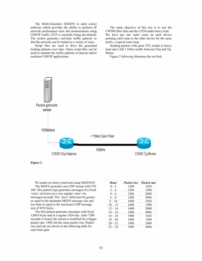
51
The Multi-Generator (MGEN) is open source software which provides the ability to perform IP network performance tests and measurements using UDP/IP traffic (TCP is currently being developed). The toolset generates real-time traffic patterns so that the network can be loaded in a variety of ways.
Script files are used to drive the generated loading patterns over time. These script files can be used to emulate the traffic patterns of unicast and/or multicast UDP/IP applications.
The main objective of this test is to test the
CWDM fiber link and the c3550 under heavy load. We have put one static route on each device pointing each route to the other device for the same prefix, a typical route loop.
Sending packets with great TTL results in heavy load and a full 1 Gbit/s traffic between Cluj and Tg-Mures.
Figure 2 following illustrates the test bed.
Figure 2
We made two heavy load tests using MGEN4.0: The MGEN generates one UDP stream with TTL
100. This pattern type generates messages of a fixed <size> (in bytes) at a very regular <rate> (in messages/second). The <size> field must be greater or equal to the minimum MGEN message size and less than or equal to the maximum UDP message size of 8192 bytes.
The first pattern generates messages with fixed 1200.0 bytes and at a regular 1024 rate. After 7200 seconds (2 hours) the stream is modified for a bigger packet rate, 1500, but the same packet size. Packet size and rate are shown in the following table for each time span:
Hour Packet size Packet rate 0 - 2 1200 1024 2 – 4 1200 1500 4 – 6 1200 2000 6 – 8 1200 4096
8 – 10 1600 1024 10 – 12 1600 1500 12 – 14 1600 2000 14 – 16 1600 4096 16 – 18 1900 1024 18 – 20 1900 1500 20 – 22 1900 2000 22 – 24 1900 4096

52
The following results were obtained for a test started at 20:00 hours: Bytes:
Packets:

53
A second test with an even stronger load was performed next day. The results were similar and brought nothing new. 5. Conclusion
The Catalyst 3550 Switch was tested over a dark fiber link exceeding with 10% the manufacturers specifications. Wire speed IP switching was obtained under any circumstances and we couldn’t detect any loss of performance neither in switching neither in transmitting the test packets.
6. References
http://www.cisco.com/en/US/customer/products/hw/switches/ps646/index.html http://manimac.itd.nrl.navy.mil/MGEN/ http://people.ee.ethz.ch/~oetiker/webtools/rrdtool/ http://www.netperf.org/netperf/NetperfPage.html http://www.cis.ohio-state.edu/~jain/cis788-97/gigabit_ethernet/

Chaotic and Quantum Neural Networks
Ciprian Ciubotariu Faculty of Computer Science, "Al. I. Cuza" University, General Berthelot Street 16, RO-700483 Iasi, Romania
E-mail: [email protected]
Abstract1
We present the main features of neural systems (self-learning, self-organization, parallelism) which are distinct from the properties of the classical (von Neumann) computers, in the context of an analogy between quantum and chaos based computation.The result is that even a simple (perceptron based) neural network model can generate chaos which (if the coupling coefficients between the neurons is strong enough) can be a source of entanglement in the corresponding quantum system.The entanglement (a nonlocal interaction) is important because in an entangled system the operations on one qubit can influence the probability amplitudes on all the qubits, without requiring wires (or other explicit physical connections) and the synchronization is instantaneous without any global clock. 1. Introduction
The explosion of interest in quantum computing is determined by its intrinsic quantum massive parallelism and entanglement, which lead to new possibilities of powerful computing and communication. In the present paper, we show (in a selfcontained way) that the ideas from standard classical neural network theory can be recasted in a quantum and chaos computational framework, using the language of ket state vectors, quantum operators and logistic maps.
It is interesting that a quantum neural computer (a type of artificial neural network) can be trained in order to be able to construct new quantum algorithms. We conclude the paper by the syntagma: chaos (or quantum chaos) generates entanglement and this can estimate its proper intensity. The paper is organized as follows. Section 2 summarizes the current interpretation of the measurement process in quantum computing readout. Usually, when one makes a measurement, the quantum computer makes a “random” (more
exactly, probabilistic) selection among the possible states (in the superposition) and chooses (collapses to) one. After the measurement, the system remains in that “collapsed state”, the possibility of other results being vanished. We also discuss the measurement in terms of the operator of projection and quantum algorithm (a measurement “searching” device) which can lead to a desired result. Then in section 3 we show that quantum entanglement can solve the two essential ingredients of a quantum computation: “quantum wire” without wire and global parallelism (instantaneous synchronization). Section 4 is dedicated to quantum neural networks (QNNs). First, we formulate in chaos and quantum terms the action of a standard perceptron. The highly nonlinear dynamics of single neurons can naturally explain the presence of chaos in neuronal networks (NNs). This is important for NN computing but also for controlling (and anticontrolling) chaos in the brain and heart. We parenthetically note that it has been suggested that the healthy state of the brain and heart is chaotic, and that more regular (e.g. periodic) behaviour may indicate the presence of some diseases. Finally, QNNs are defined on the basis of the qubit entanglement. It is shown that a nonlinear quantum computer, based on a nonlinear quantum (e.g. Schrödinger) equation, should be described, in order to obtain an exact definition of a quantum perceptron. 2. Quantum computing readout
A qubit (quantum bit) represents a quantum two-state (two-level) system (e.g. spin states, energy states, atomic states, photon polarizations), described by a 2D complex vector space (with Hermitean scalar product, i.e. a Hilbert space H ) [1]. The quantum state
2
ψ of a qubit can be
defined as a superposition, 0 0c cψ + 1 1 , of two logical states of usual bit (False, True or
0 0 0ψ ≡ , 1 1 1ψ ≡
0 1 c , c), where c and
are complex numbers ( ), and the two 0 1c
∈
1 Paper accepted to be presented at the RoEduNet International Conference on Networking in Education and Research (2nd edition) Iasi, June 5-8, 2003. Scientific Commitee-RoEduNet-Ed.
54

pairwise orthogonal unitary state vectors,
( )0 1 0 T and ( )1 0 1 T , represent a
standard computational basis in H . The state vectors
2
ψ and α ψ (where 0∈ −α ) represent the same physical state (the same point in complex projective space).
ψ
iψ
φ≡
φ
φ⇔
ψ
ψ
1 1
0 0
N N
i i
− −
= =∑ ∑
ar−
State vectors can be interpreted as rays in Hilbert space (or elements, points in complex projective space of rays). Due to projectivity (and liniarity of quantum mechanics) one can consider only states with unit norm.
The norm ψ of a normalized (unit) is given by the sesquilinear (due to the complex conjugation of the second vector) Hermitean scalar product,
( )1
2
0i i,ψ ψ ψ ψ ψ ψ∗
=
≡ ≡ = ∑ c c∗
2 20 1 1c c == + . (1)
A measurement process (a readout, an outcome) in quantum computing consists in determination of the probability of registration
( ) ( )2 , 2φ ψ ψ φ ψ→P , (2)
where the state vector ψ describes the qubit (or
generally, the quantum system) and represents the state of the measurement device. (The simplest examples are the Stern-Gerlach experiment for electrons and the polarizer for photons [1]. The measurement collapses qubits to single classical values.) Of course,
( ) 2 1φ ψ ψ φ α ψ→ = =P . (3)
In other words, the state φ of the measurement device acts as a filter (a two-answer “binary searching device”) for the state of the qubit.
(True) iff ( ) 1φ ψ→ =P φ and represent
the same physical state. If φ α ψ≠ ,
(False). In the particular case of an
orthogonal basis in the Hilbert space,
( ) 1φ ψ→ ≠P1φ = ,
i j ijψ ψ δ= , i ic i iφ ψ ψ≡ φ ,
i ic φ ψ=
2nN =
. Now we have an answer of the measurement device and we can obtain one of the alternatives of readout with the
probability
yN
( ) 2i icφ ψ→ =P .
ψ
We note that a measurement can be considered as a quantum transition from the state ψ of the
qubit to the state φ (of the measurement
“searching” device) with the probability ( )φ ψ→P [1].
φ φ φP
Also, we note that a simple measurement device can be implemented by the operator of projection
, defined by [2]
( )φ φψ ψ φ φ ψ≡ =P P . (4)
Thus, ( )φ ψP performs the readout (registration) of
a state ψ with the probability
( ) 2ψ φ φ ψ→P if 1φ ψ= = (5) or, generally,
( )2φ ψ
ψ φφ φ ψ ψ
→ =P . (6)
The expression ( ) 2ψ φ φ ψ→P characterizes also the fidelity of the quantum channel qubit-measurement device. 3. Entangled qubits
In a classical circuit, we can move wires from one place to another, but in a quantum circuit there are no quantum wires. It is very difficult to move a qubit from place to place or, more exactly, we cannot clone an unknown quantum state. In other words, no wires, no oscilloscope probes, and no debugging print statements can be generated by a quantum circuit.
If a superposition of states of two qubits is not entangled, i.e. is decomposable,
( ) ( )1 110 11 1 0 1 12 2
+ ≡ ⊗ + ⊗
(1 1 0 12
≡ ⊗ + ) , (7)
one can measure the first qubit without altering the state of the second. By contrast, the Bell (maximally entangled) basis vectors (Fig. 1),
(100 1 0 0 12
TENTUΦ+ = ) , (8)
( )110 1 0 0 12
TENTU− = −Φ , (9)
(101 0 1 1 02
TENTUΨ+ = ) , (10)
(11 1 1ENT ENTU UΨ− ≡ ⊗ ) , (11)
(where ( )2ENT XOR HU I⊗U U =entangling gate, TM is the transposed of matrix M ) are
indecomposable entangled states [3].
55

An entangled state, for example Ψ , is not even a superposition of states
+
0 and 1 because Ψ+ is not separable; the state of the first qubit is entangled with the state of the second. Only after a measurement (an interaction, a projection, an observation), if we find that the first qubit q is in
the state 0
0 , we can assert that the system is (not
“was”) in the state 01 0= ⊗ 1 . Furthermore, an unknown quantum state cannot be deleted without altering the rest of the system. The entanglement of quantum states can be estimated in terms of density matrices. For example, if a qubit starts out in a pure state 0 10c cψ + 1 , its equivalent density matrix description is given by
( )2
0 0 12
0 1 1
c c c,
c c cρ ψ ψ ψ ψ
∗
∗
=
. (12)
Finally this section, we note that entangled states exhibit nonlocal correlations in the sense that two entangled systems which have interacted in the past and are no longer (directly) interacting still display correlations.
4. Entanglement of quantum neural
networks
The idea of quantum computing led immediately to the quantum network concept (e.g., quantum cellular automata, quantum neural network -QNN, etc) [4]. The main features of a neural network (NN) which are distinct from the usual characteristics of a classical von Neumann computer are: (i) The algorithms and hardware are intrinsically parallel. NN processing is realized by a huge number of complex correlated processor units (neuron cells). All these processing elements realize a massivelly parallel computing. (ii) A NN can learn and self-organize from experience, i.e. a NN is trainable. Training correlates the input with the output of a NN by adjusting the synaptic weights (see below). At the beginning of a training process the input-output correlation is simply deterministic (or probabilistic) and then it evolves spontaneously to a self-
organized structure (unsupervised learning). If in a NN the weights are changed (tuned) in accordance with a desired output we deal with a supervised learning. ⊕
1q
0q
( )2ENT XOR HU I⊗
2I
Figure 1. U U
H
(iii) A NN can work even if the data are incomplete, inconsistent or noisy and thus, a NN is fault tolerant. (iv) A NN presents an associative recognition of complex structure [5]. All these features are also proper to a quantum computer. We will emphasize this idea in terms of a quantum neural network (QNN), which represents a type of artificial NN (ANN, also known as parallel distributed processing or connectionist architecture). First, we note that a neuron ( receives )in inN real
(input) signals ( )1 2 in j 3 x , j , , N= , , … (an input
vector x ) from many other neurons (and, generally, from the environment) by “network wires or interfaces, or yet junctions” or “network channels” or yet connection weights (synapses) which weight via (that can strongly influence, e.g. synaptic currents can cancel each other – “inhibitory interference” or synaptic currents can amplify each other – “excitatory interference”, in quantum optical terms) the signals. connectivity matrix can be interpreted as the weight of the connection from the output of neuron to neuron i .
ijw
ijw
j The connection weights (strengths) store the knowledge necessary to solve specific problems and, from this point of view, they represent a distributed memory which contain an essential part of the NN “computing algorithm”. Thus, the neuron is activated by a global input ( which represents a sum of the weighted signals.
)iz
If the global input exceeds an adjustable threshold (offset=set-off=a sum or value set off against another sum) value ( iτ ) (an external bias in an ANN), the neuron generates (via a transfer-gate function Θ , which generally is nonlinear and is also called the squashing function) a global (final) output synaptic current (output signal) (an
output vector ( )( )i iy zΘ
y ) which is sent to other neurons it is connected to. In other words, the output of a neuron can fan-out to several other neurons (A fan-out represents the number of inputs that can be driven by a single output, and this is not necessarily a well-defined number). The neural information processing is illustrated in Figure 2. The global input ( )iz (the activation function) can be modelled by a linear function of the inputs as follows:
1
inN
i ij jj
z w x iτ=
= −∑ . (13)
56

The transfer function can be approximated by the step function or by a differentiable, smoothed version, the S-shape asymmetric (unipolar) sigmoid-logistic function :
( )zΘ i
p
σ
0
1
FRACTAL
CHAOS
Oscillations Non-chaoticbehaviour
3.5 3.632.4 2.8
Inputs
3x
2x
1x 1iw
2iw
3iw
iz ⇒iyin
( ) ( )i iz zσΘ ≅
1
0 ( )iz xSeparation hyperplane
Sigmoid function
Output
Transfer gate
Activation
Weights
Neuron
Figure 3. Bifurcation diagram (a fractal). At p=3.57 is the onset of chaos. If one zooms in on the value p=3.82 (non-chaotic points) the
situation looks like the whole diagram (similarity property of fractals).
Figure 2. A standard perceptron in which the neuron is able to sum many inputs modified
by adjustable weights. For points appertaining to one half-space the result of “perceptron computation” is , and for points appertaining to the other it is 1 [6]. This (linear) separation can be formulated in terms of the Heaviside step function as follows:
0
( )( ) 11 exp( )
zz
σγ+ −
, (14)
( ) 10 ifif ii i
zz z≥= <H 0
0 . (17) where γ is a positive constant (or variable) which controls the steepness (slope) of the sigmoidal function [6].
If one consider the extended ( )1inN + -dimensional input vector, In order to formulate the role of the chaos theory
in the study of a NN, we recall that the logistic function satisfies the first-order nonlinear differential equation,
( )0 1 2 3in in jx x , j , , , , , N= …
( )0 1 21in
Nx , x , x , , x≡ = … , (18)
(1ddzσ )γσ σ= − , (15) and the extended weight matrix (vector) of the
perceptron , in ( )i iw≡ jw ( )0 1 2 3 in ijw , j , , , , , N= … which is the continuous version of the logistic map,
( )1 1k kp kσ σ σ+ = − , (16) ( )0 1 2 in
i i i i iNw , w , w , , wτ …≡ − , (19) where p represents a positive parameter. The bifurcation diagram summarizes the behaviour of the logistic map (Fig. 3).
the “extended neuron” represents a zero threshold perceptron. In an ANN, the individual perceptrons (i.e. neurons with their adjustable weights and thresholds
in iw
iτ ) are connected together into the network to process information from a set of input neurons (with the corresponding input vector) to a set of output neurons (with the corresponding output vector).
The sigmoid-logistic function can be also defined as a saturating function in the sense that it forces all negative values below –1 close to 0, positive values above 1 close to 1, and intermediate values between –1 and +1 to appertain to the domain from 0 to 1. We note that the fixed value of the global input determines (in the input space, Fig. 2) a
separation hyperplane,
0iz =
j i1
inN
ijj
w x τ=∑ =
N
, which
divides the input (Euclidean) space ℜ into hemispheres (generally, into two half-spaces) with negative and pozitive activations.
in
In quantum computing terms, a network processing can be implemented by an operator
(acting on the input vector), which depends on the neuron connectivity weight matrix and propagates the information forward in space (or time) to calculate an output vector.
ANNUw
57

58
( ) ( ) ( )1 ( )j j jˆ ˆU t U t d y t qη+ = + − , (25) The main difficulty in the definition of a
quantum neural network (QNN) consists in the fact that the essential “gate” of an ANN (the transfer-gate function ) is nonlinear. The nonlinearities are inevitable whenever there arise internal interactions (as in a perceptron) between various degrees of freedom. Thus, a NN computing can be formulated in terms of a deterministic (chaotic) computing rather than in relation with a quantum information processing, which is based on the linear (in the wave function) Schrödinger equation,
Θwhere d is the desired output. Even if it can be shown that this quantm rule drives the system into a desired quantum state d , the Altaisky algorithm
[4] does not represents a quantum one because U is not a unitary operation. Such an algorithm is merely a quantum inspired algorithm.
ˆ
( ) ( ) ( )2
2
02i x, t V x x, t
t mψ ψ
∂= − ∇ + ∂
Further developments of QNN include nonlinear effects in quantum computation and the definition of new dissipative irreversible gates (D-gate) [8], [9]. Acknowledgements
(a simple approximation of a more general nonlinear quantum equation). Elaboration of a nonlinear scalable quantum computer, based for example on a nonlinear Schrödinger (Landau-Ginzburg) equation,
I would like to express my gratitude to Prof. dr. Nadir Belkhiter (Département d'Informatique et de Génie Logiciel, Université Laval) for encouragements. Partially, this paper contains some results of the author’s bachelor thesis (June 2003) in computer science (supervisor Prof. dr. Victor Felea). I also included the precious knowledge I acquired from Prof. dr. Octavian Brudaru and Prof. dr. Octavian Rusu as I attended their courses of “Neural Networks” and, respectively, “Communication Networks”.
21 2C C
tψ ψ ψ∂= +
∂ψ , (20)
will pave the way to an exact definition of a QNN. However, for the time being, a QNN can be described in terms of linear optics (beam splitters, phase shifters, photon sources and photo detectors) in the same manner in which the quantum computation can work [7]. The idea is to consider that a perceptron is sensitive not only to the amplitude of a signal, but also to its phase.
References Taking into account all the above remarks, we
can define a quantum perceptron as a quantum system with an input register, n qubit−
[1] Alexander Vlasov, “Quantum Computation and Images Recognition.” quant-ph/9703010, 7 Mar 1997, pp. 1-7 (Talk given at QCM'96).
0 1 1 nq , q , , q −… , (21) [2] Alexander Vlasov, “Analogue Quantum Computers for Data Analysis.” quant-ph/9802028, 11 Feb 1998, pp. 1-7.
and an output derived by the NN perceptron rule, 1
0
n
j jj
ˆ ˆy f U q−
=∑ , (22) [3] W. –H. Steeb, “Quantum Computing and
SymbolicC++ Simulations”, Int. J. Mod. Phys. 11 (2) (2000) 323-334. where jU are the matrices acting on the
standard basis
2 2×
, and 0 1 , f represents an unknown (activation) transfer gate (operator) that can be induced by the network of quantum gates [4]. In order to maintain the linearity (but, generally, not unitarity) in quantum computing network, we consider the case , and thus the output of a quantum perceptron can be written as:
1=f
[4] M. V. Altaisky, “Quantum neural network” quant- ph/0107012, 5 Jul 2001, pp. 1-4 (Technical Report). [5] Hermann Kolanoski, “Application of Artificial Neural Networks in Particle Physics”, DESY 95-061, April 1995, pp. 1-11. (Invited talk given at the Vienna Wire Chamber Conference 1995). [6] Yorick Hardy and W. –H. Steeb, “Classical and Quantum Computing”, Birkhäuser Verlag, Basel, 2001.
( ) ( )1
0
n
j jj
ˆy t U t q−
=
= ∑ . (23) [7] E. Knill, R. Laflamme and G. J. Milburn. “A scheme for efficient quantum computation with linear optics”, Nature 409 (2001) pp. 46-57. In analogy with classical supervised learning rule
(i.e. updating the weights), [8] Gilson Giraldi, Technical Report, http://virtual01.lncc.br/~giraldi/qc/Quantum-Neural-Nets/Research.
( ) ( ) ( )1j j jw t w t d y xη+ = + − , (24) [9] S. Gupta and R. Zia, “Quantum neural
networks”. Technical report, http://www.arxiv.org/PS_cache/quant-ph/, 2002, pp. 1-30.
where is the discrete time, is the desired output, and
t d0 1η< < represents the step size [4], a
quantum learning rule can be written as:

Distribution of Quantum Information I. Quantum Entanglement
Ciprian Ciubotariu
Faculty of Computer Science, "Al. I. Cuza" University, General Berthelot Street 16, RO-700483 Iasi, Romania
E-mail: [email protected]
Abstract1
One of the important tasks in quantum-information processing and quantum computing is the distribution of quantum information encoded in the states of quantum registers. Quantum gates XOR and SWAP can be considered as simplest examples of (high fidelity) transfer of information inside a multipartite system. Because of the well known difficulties (e.g. the no-cloning theorem, decoherence, the superselection rules) in performing a pure exact quantum transfer of information, in the present paper we consider a simulation of the information distribution on the basis of some analogies between quantum and chaotic phenomena. We show that quantum information and deterministic (chaotic) information are two “state phases” of a general information process. 1. Introduction Quantum entanglement (QE) of states (as a resource similar to mass or energy) has a key role in quantum information processing (superdense coding, quantum teleportation = “one-to-one” quantum communication, teleclonning approximate “one-to-many” quantum communication), which can be considered as complementary to the role of classical information [1]. Entanglement generates nonlocal correlations of quantum states in the sense that two entangled qubits which have interacted in the past and are no longer interacting still display correlations. There are no “quantum wires” and, possibly, the single efficient mode to distribute quantum information is the quantum teleportation (QT) scheme based on QE (Classical correlations cannot have the efficiency of the quantum nonlocal correlations). In terms of a QT mechanism, quantum information of an unknown state of an input qubit can be faithfully distributed from a sender A (Alice) to a remote receiver B (Bob) by an initially pair of
≅
maximally entangled qubits (a real “quantum information channel”) [2, 3]. An “information-state-phase transition” appears if the knowledge of the initial data (i.e. the initial computational grid) reaches the size of a quantum
cell (a ‘lit volume pixel’ of size ). The role of the two basic approaches, quantum computing (part I) and chaos (part II), is analyzed in the context of a chaos based (continuous and discrete) cryptography. Quantum teleportation and covariant distribution of reasonably faithful copies of information-bearing states can be simulated by synchronized and controlled chaos in a qubit-like double scroll (e.g. Lorenz) circuit (part II).
3h
2. Bits, cbits, qubits, pure and mixed
states We recall that a (classical) bit (cbit) represents one of two states, and 1 (False and True, No and Yes, ...), implemented by e.g. the state of a switch or a voltage, or a charge state of a capacitor. This Boolean values can be extended into quantum mechanics, choosing two (orthgonal) states
0
0 and
1 (e.g. horizontal ↔ and vertivcal
polarizations of a photon), which also map to and . A quantum bit (qubit) is more, it is a level
particle, it can be not just
021 d =
0 and 1 , but any
(complex) linear superposition, 0 1c c+0 1ψ = , that satisfies the normalization condition,
2 20 1 1c c+ = . Thus, unlike classical bits, quantum
bits can be in a continuous range between 0 and 1 . For example, a qubit can be a horizontally plane polarized photon state ( 0↔ ), representing a (plane) light wave travelling in the direction, with the electric vector
z −
( ) (e e exp ix x x )E cos kz t kz tω ω= − ≡ − Re ,
a vertically polarized one ( )1 , 1 Paper accepted to be presented at the RoEduNet International Conference on Networking in Education and Research (2nd edition) Iasi, June 5-8, 2003. Scientific Commitee-RoEduNet-Ed. ( ) (e e exp iy y y )E cos kz t kz tω ω= − ≡ − Re ,
59

a right circularly polarized one 1 112 2
( 0 +i ) ( +i )rcp ≡ ≡ ↔
(a helicity eigenstate), a left circularly polarized one 1 12
( 0 i )lcp - ≡
(the second
helicity eigenstate), a light polarized at 4π
,
41 112 2
( 0 + ) ( + )πψ ≡ ↔
, or
any other linear combination. (The state vectors ψ
form a two-dimensional Hilbert space H .) We mention that although a photon is a spin-1 particle, it has only two spin (or more exactly, helicity, i.e. angular momentum along the axis of propagation) degrees of freedom because it is massless. Left- and right-hand circular polarization states are helicity eigenstates and, because helicity is defined with respect to the propagation direction of the photon, the two states of polarizations can be defined only locally (i.e. without a shared standard) [2].
2
Another well known implementation of a qubit is a spin-1 particle, such as an electron or a nucleus, which also has a
22 D− Hilbert space
associated with it. The states ( 2H ) 0 and can be defined as eigenstates of one (e.g. ) component of the (spin) angular momentum operator.
z
The relationship between plane and circular polarization is a relationship of linear superposition [3], in the sense that two plane-polarized photons can generate a circularly polarized photon, and vice-versa:
( )12rcp ix yE E E= + , (1
2 rcp )x lcpE E E= +
(12 rcpiy lE E E= − )cp . (1)
The (polarized) states presented above can be called “pure states” because they have a determined state of polarization. However, an unpolarized beam of photons does not correspond to any polarization state and thus it is not a superposition of two independent polarization states (“basis state vectors”) with definite amplitudes and phases. This beam represents a “mixed state” or a mixture of states. A mixed state can still be considered as a superposition of xE and yE with equal amplitudes but with randomly varying relative (time-dependent) phase (i.e. an incoherent mixture of pure states), that is the relative phases of the states in a mixture are not specified. In other words, a superposition of pure states is also a pure state but a mixture of states is not a state; it is merely a mixed state. If a quantum system is in a pure state ψ , the
expectation value of an observable O associated with the system is
ˆˆO Oψ ψ . In the case of a
mixed state it is not possible to specify completely a certain state but one can indicate a probability for
finding the system in the state
iP
iψ , and one can
define an average expectation value of O (a weighted sum),
ˆ
1
0 1 E ,
ψ
i i ii
ˆO Oψ ψ∑P . (2)
It is important to note that if we observe (i.e. measure) the state of a qubit, the result is invariably 0 or 1 , corresponding to Boolean , 0 and 1 .
However, until we measure [4], it can be an arbitrary superposition (“mixture”) of 0 or 1 . A (single-valued, finite, satisfying certain boundary conditions in the quantum processor) solution ψ of the time-independent Schrödinger
equation ( ( )2
2
00
2E V
mψ ψ∇ + − =
E( )E
, a Sturm-
Liouville type equation) exists only for certain values of the (energy) parameter called the (spectrum σ of) eigenvalues, which define the energy-level (or ’frequency’) discrete spectrum of the system (e.g. of a qbit): 2, EiE E ,
( )Eσ≡ . The corresponding solutions,
0 1 2 , , ,ψ ψ
H
iψ ψ , are called eigenstates or eigenfunctions (or eigenvectors, or wavelets in a Huygens' principle formulation). The Schrödinger equation Eψ ψ= can be interpreted as an ‘eigenvalue (or eigenstate) equation’, where represents an eigenvalue and Eψ is its eigenstate of the energy (Hamiltonian) operator. Sequential measurements are in agreement with the von Neumann’s projection postulate, which asserts that if a measurement has as outcome an eigenvalue ( )EE σ∈ , then the state of the
quantum system evolves from its initial state to
( )EP ψ . Thus, an immediate next measurement
generates again as output since represents itself an eigenstate with eigenvalue . In a way, ‘projectors encode true state transitions’. Between measurement, the state vector evolves in time according to the time-dependent Schrödinger equation.
EE
A ’pure’ (coherent) quantum processor represents a set (an ensemble) of identical (fermion
60

or boson) noninteracting particles (qbits) (e.g. electrons or photons). If a qubit has a finite probability of being in two states iψ and kψ , the total (time-dependent, ’superpositioned’) state vector is given by the ’sum of state vectors’ (superposition)
i i
e eiE t E tik i i k k
kα ψ α ψΨ− −
= + , (3) and the probability density of the spatial distribution of the states of the quantum ensemble is
ddik ik i i i i k k k k
pV
α αψ ψ α α ψ ψΨ Ψ∗ ∗ ∗ ∗= + ∗
( ) ( )i k i ki it E E t E E
k i k i i k i ke eα α ψ ψ α α ψ ψ− − −∗ ∗ ∗+ + ∗ .
Let us assume that a QR is in a state described by the state vector ψ . In order to find the probability that the (readout, outcome) measured value of the physical quantity (observable) operator is one of its possible eigenvalues , we expand
HiE ψ (as in
the case of the Fourier series) into a series of the eigenvectors iψ of , that is H i i
iψ α ψ= ∑ ,
where 2
iα are the probabilities ( )iEP2 2
iiψ ψ ψ≡
iE
ψ of obtaining the eigenvalues
as a result of quantum computing measurements. If the eigenvectors satisfy the orthonormalization
conditions i j i jdV ijψ ψ ψ ψ∗ δ≡ =∫ , we can
write 2 1idVψ ψ i i
i iψ ψ α α∗ ∗ α= = ≡∑ ∑ =∫ ,
and the mean (expectation) value becomes
We note that the presence of the mixed terms (proportonal to the products i kα α∗ , k iα α∗ ) in a pure quantum (fermion or boson) processor leads to the wave phenomena of interference (and diffraction) of the de Broglie (quantum) waves. By contrast, in the case of a mixed (incoherent, with rapid change of the phase difference between state vectors) ensemble, the mixed terms disapear, no wave phenomena (e.g. interference, diffraction) are present, and the probabilities and not the state vectors are added, i.e.
† dˆ ˆ ˆ ˆA A V A Aψ ψ ψ ψ ψ∗= ≡ =∫ ψ
( )i ii
E E= ∑ P =2
i ii
E α∑ . (5)
2 2i k
2ψ ψΨ = + . (4)
The behaviour of one qubit (microparticle) or several qubits (quantum register, QR) is described by the state vector ψ , which has a probabilistic nature. Thus, quantum mechanics gives only the mean (real) value of a physical quantity associated with a Hermitian operator . In other words, an observable physical quantity (i.e. a quantity that can be actually measured and computed in a quantum computer) can be characterized only by its mean value. If an operator has only one eigenvalue ( ) and one state eigenvector (
H
HE ψ ), the mean
value of this operator coincides with the eigenvalue. However, if an operator has several eigenvalues
corresponding to the
eigenvectors
H0 1 2 E E , E , E ,i
0 1 2 , , ,ψ ψ
HiE
iψ ψ , an exact ’in-situ’ measurement of the (observable) physical quantity (the output of a quantum computing) corresponding to the operator can lead only to one of eigenvalues , the state vector of the QR becoming the corresponding eigenvector
iψ . This reduction of the state vector from a complex superposition to a particular eigenvector (as a result of a measurement-projector action) is called the collapse of the state vector.
3. Entanglement and ebits Quantum computing needs a collection of qubits, that is a quantum register. Consider first a 2 qubit− register described by the orthonormal bases for qubits (I) and (II):
0 1( ) ( )I I, and 0 1( ) ( )II II, . (6)
If the 2 qubit− register is prepared in the entangled
(normalized) state (a Φ+ Bell-like state) 00 0 0( )( ) ( ) ( )I II I IIcψ ψ = ⊗
11 1 1( ) ( )I Ic+ ⊗ I , 2 200 11 1c c+ = , (7)
the two qubits are correlated in the following sense. If one measures qubit I by projecting the state onto
the 0 1( ) ( )I I, basis, the result 0 I is obtained
with the probability 200c , and the measurement
initializes the state 0 0 0( ) ( )I II⊗ 0 . We
emphasize that because we “observed” 0 I as a result of a measurement, the state of the system is now 00 , and therefore the second qubit is now
0 II . But it wasn’t 0 II before since it was entangled with the first qubit. Similarly, if after measurement, one gets 1 I (with probability
61

Tr ψ ψ= (9) 211c ), the state of the system is now 1 1( ) ( )I I⊗ I
and thus the second qubit is now (not before) 1 II
2(II)I⊗
. It results that (by the measurement of the qubit I) we have found the exact state (with probability one) of the qubit II even if this was somewhere else (possibly in a remote, hidden, inaccessible place) with respect to the qubit I. In other words, the state (2) of (interacting) qubits I and II is entangled and manifests nonlocal correlations.
IU
)I
( )1 1I I
)
represents the (unit trace, Hermitean, positive, i.e. its eigenvalues are nonnegative and ∈ ) density operator (or reduced density matrix, i.e. partial trace obtained by tracing the whole system’s pure state density matrix
[0 1 , ]
=ψ ψD over the first qubit’s degrees of freedom) for qubit I [4]. For example, if
00 11 1 2c c= = ,
( ) ( ) ( )II ITrρ ψ ψ Let us now formulate more generally the nonlocal correlations in terms of the density operator (or density matrix) for one of the two qubits. We consider an observable U U acting
on qubit I only, where U is a self-adjoint
(Hermitean, ) operator acting on I,
and is the identity operator acting on qubit II (Fig. 1).
(I)I H
(I)H†
(I)HU(I)HU =
2(II)I
( ) ( )2 20 0I Iψ ψ= ⊗ ⊗
( ) ( )2 211 12
I Iψ ψ+ ⊗ ⊗ = 2I . (10)
Generally, a quantum density matrix =ψ ψD (for an ensemble of particles prepared in a pure state ψ ) gives the distribution of quantum states ψ in
the ensemble of particles. It is Hermitean and all its eigenvalues are between and 1 . In a way, the density matrix is related to the quantum measurement process. Indeed, for a pure state
0
Iψ ,
the density matrix ( ) ( )I I Iρ ψ= ψ represents
the projection onto 1 D− space of ( )Iψ . The
probability that a qubit is found in an eigenstate φ
of the measurement is φ φD . A quantum measurement is formally implemented in a quantum circuit by an idempotent self-adjoint measurement (projection, dyad) operator Pψ ψ ψ (on a
given normalized vector ψ ), which projects any
vector φ into its component along ψ . Simple examples of measurement ope
The expectation value (a “mean value”, or a value of an observable in a given state associated with the scalar product involving just that state vector) of the observable IU with respect to the state (2) is, by definition,
(I)HU
IIq
Iq
2(I) (II)I HU U I⊗
Figure 1. The unitary transformation (gate)
( )( ) ( )( )II II I IIUψ ψ rators are:
2(I) (II)( )( ) ( )( )HI II I IIU Iψ ψ≡ ⊗ ( ) ( ) ( )0 001 1 00 0 1 00 0 0
† 2ˆ ˆP P≡ = ≡ ≡ P ,
( ) ( ) ( )1 110 0 01 1 0 11 0 1
† 2ˆ ˆP P≡ = ≡ P≡ , ( ( ) ( )00 0 0IIIc∗= ⊗ + ( ) ( ) )11 1 1IIIc∗ ⊗
with the completeness equation, ( ( ) ( )00 0 0I IIc ⊗ + ( ) ( )11 1 1I Ic ⊗ 20 10 1
† †ˆ ˆP P P P I+ = . (11)
( ) ( )2
00 0 0HI Ic U= ( ) ( )2
11 H Ic U+ If the state of the system is 1 (just before a
measurement 0P that project 1 onto the basis
vector 0 is performed), the probability that result
(measurement outcome, readout) 1 occurs is given by
( )( )(I) (I)TrH H IU U ρ=
( ) ( )( 200 0 0(I)Tr H I IU c≡
( ) ( ) )211 1 1I Ic +
, (8) ( ) 001 1 1†P P 0= =P , (12) where the operator
( ) ( )( ) ( )(2 2
00 110 0 1 1I I Ic cρ + and
( ) 000 0 0†P P 1= =P . (13)
62

Thus, outcome of a quantum measurement is not deterministic; for a qubit the probability that we
obtain the result 0 is 20c and the probability that
we obtain the result 1 is 21c .
The “pure” state (2) is entangled (or nonlocal) because there is no way to write it as a tensorial product state of the two qubits. As a measure for entanglement we can take the quantity (entropy of entanglement, a von Neumann entropy)
( )( ) ( )( ) ( ) ( )2Tr logI II I II I Iρ ρ ≡ − S E (ebit) (14)
in the “ebit” unity (1 bit of entropy, i.e. the amount of entanglement in a maximally entangled state of a pure bipartite state with 1=E ) [1]. For example, in the case of Bell states (eq. 5),
( )( ) ( ) ( )2Tr logI II I Iρ ρΦ+ − = E E
= =1 . (15) Φ Ψ Ψ− + −= =E E E ebit
( ) (1 110 11 1 0 12 2
ψ = + ≡ ⊗
( )1 1 0 1 12
≡ ⊗ + ⊗
( )( ) ( )( ) ( ) ( )2 0Tr logI II I II I Iρ ρ ≡ − = S E
( )Iρ ( )IIρ
( )( )I IIψ
n n qubit−
If a superposition of states is not entangled e.g.
+ )
, (16)
. (17)
Finally this section, we parenthetically note that the value of the Schmidt number (the number of nonzero eigenvalues of or ) can also be a
criterion for the identification of entangled states. A bipartite pure state is entangled (or
nonseparable) if its Schmidt number is greater than one [5]. 4. Quantum computing A quantum computer (QC) is represented by a finite number of input qubits (the input register), an equal number of output (superposed) quantum states generated by a “black box” global gate (the quantum processor) wherein some ‘simpler’ local quantum gate can operate. All these quantum elements are ‘wired’ up by a number of input and output lines equal to the number of qubits involved in the quantum register (QR) (Fig. 2). A quantum computation begins by assembling (through entanglement, a very hard practical task) the input qubits, and prepare them in a standard inital state, e.g.
n0q = , i.e. 0 0q = , 1 0q = ,
... , 1 0nq − =U
. Then, one applies a unitary transformation (the global gate) to the n input qubits. The global gate black box is implemented as a product of elementary standard quantum (local) gate
(the universality theorem of elementary quantum logic gates). After the application of U (quantum processing), one measures all of the qubit’s states (strings of and 1 ) by projecting onto the
2nN =0
0 1, (standard) basis. This measurement outcome represents just the output (a classical information that can be printed, the readout and further, fanout i.e. the result of a quantum computation is propagated over a number of data acquisition units) of the quantum computation [4]. Quantum parallelism (in physical terms, the superposition principle) means many states at a time, and quantum programming (or quantum algorithm) means constructive (maximum) interference of those probability amplitudes which Quantum
processor BLACK
BOX (Global gate)
Output register Many states at a time qbit 0
Input QR
Supe r pos i t i on
Paral le l i s m
Cons tructive
Interference
qbit
0
0
0
Initialization 0
¬
XOR
Localgates
XOR
1n−
Figure 2. A QC as a concurrent system (par excellence) and the universality
theorem of elementary quantum logic gates. The direction of the arrow
represents the flow of time. The dashed lines represents two positions of the
parallel processing quantum wave front (the Huygens’ envelope of wavelet
eigenvectors, a basis in Hilbert space).
Read-out Fan-out
correspond to the desired result. By contrast, classical parallelism (classical parallel computer) means many things at a time, and a classical programming means the synchronization of a multiprocessor system (communicating through shared memory) in order to operate coherently, without disruptive functioning.
In a quantum (probabilistic) computer device, because of the decoherence (i.e. interaction with the environment or leakage of quantum state information into the environment, or yet
63

entanglement with the environment), it is very difficult to do more than a limited number of computation reliably in a very short (e.g. 1 ns) [6], [7]. The solution is to use the massive parallelism of quantum computing.
In some quantum algorithm implementation the input register (n qubit− inp
nR ) is initialized (prepared) as a superposition of states, e.g. an equal amplitude superposition of all integers (or binary strings is ) from to 0 2N n= ,
( )1
0
1inp
Nn
ii
R sN
−
=
= ∑
0 1 00 0 11 1( )
i
ii i
m
n mm n mPermutation
N
=
− ×= ×
=
∑ , (18)
a global unitary quantum gate (a quantum operator), and the ouput register (n qubit− out
nR ) (Fig. 2). The quantum gate operates in parallel on all
strings simultaneously. A quantum algorithm is implemented in the global unitary gate so that it maximizes the probability that the (collapsing) output we observe (measure) coincides with the result we search.
2nN =
A quantum network or a quantum circuit (a quantum processor) contains a number of parallel tracks (no wire) on which qubits (more exactly, the states of qubits, the processing wave) sinchronously propagate as a global quantum wave in a tensorial product Hilbert space,
1 11
global n nn
i i i ii i
α ψ ψΨ = ⊗∑ ……
⊗ , (19)
where 1 ni iψ ψ correspond to local (individual
qubit) state vectors. We emphasize that, as in the case of any wave propagation process, the quantum processing wave is passive in the sense that qbits (as fixed points in space, or as quantum dots) remain fixed in the quantum processor but their states are travelling through quantum circuit until their read-(fan) out. The situation is similar to that of a ’passive coordinate transformation’ in spacetime. Now, the concepts of ’passive probabilistic quantum teleportation’ and ’passive probabilistic quantum clonning’ seem to be more intuitive. Generally, a quantum computing system (a quantum processor, or a quantum information processing) works on the basis of the following steps (or setup): I. Quantum kinematics (or “preparation of quantum registers”), which represents the description of the states of the system. II. Quantum computing (reversible) dynamics, which represents the description (e.g. by unitary logic quantum gates or operators) of evolution. Unitary transformations are isomorphisms of the Hilbert space projection lattice. III. Quantum measurements (or quantum state update due to measurements performed on the
quantum system, or projections, in mathematical terms), which has a non-classical irreversible content. The state update can be considered as a dynamical process which generates an uncertainty (and thus an unpredictability) on the result of a measurement. Projections are not isomorphisms of the Hilbert space projection lattice. We finally remark that, because of the randomness of the quantum measurement process, a quantum algorithm implemented in a QC is merely a (quantum) probabilistic algorithm in the sense that one can run exactly the same algorithm twice and the results can be different. In other words, a QC generates a probability distribution of possible outputs. 5. Depth of a quantum circuit and
ancillae
A one-layer quantum circuit contains the tensor product of one- and two-qubit gates, i.e. rank 2 and 4 tensors (in Hilbert spaces), or 2 ×2 and 4 ×4 unitary matrices. In other words, a one-layer quantum circuit represents a quantum operator that can be performed by a set of simultaneous one-qubit and two-qubit gates, where each qubit interacts with at most one gate [8], [9]. A quantum circuit of depth k represents a quantum operator written as the product of k one-layer circuits. Thus, the depth of a quantum operator is the depth of the shallowest circuit equivalent to it.
We consider an arbitrary two-qubit gate, the controlled-U gate (Figure 2),
22 23
32 33
1 0 0 00 1 0 00 00 0
UCu uu u
, (20)
which, particularly, can be a controlled-NOT gate,
or (21)
1 0 0 00 1 0 00 0 0 10 0 1 0
NC ↓
1 0 0 00 0 0 10 0 1 00 1 0 0
NC ↑
where the first qubit is called the control (input, • ) qubit, and the second is called the target qubit ⊕ . In quantum mechanical terms, this separation (control - target) is artificial because the CNOT gate does not leave the control qubit (which can be entangled with the target qubit) in an unaltered state.
Uθ
⊕NC ↑
⊕UC NC ↓
U
Figure 3. Controlled-U, CNOT(down), CNOT (up), and symmetric phase shift
64

It is well known that such gates as those represented in Figure 1 can be combined with one-qubit gates to implement any two-qubit operator [8]. The symmetric phase shift Uθ is given by
U
1 0 0 00 1 0 00 0 1 0
0 0 0 ie
θ
θ
(22)
Another ingredient necessary for intermediate steps in the quantum computation is represented by the use of auxillar (additional) qubits (“ancillae”), which are equivalent to additional processors in a parallel classical computer [8]. As a condition to avoid entanglement, the ancillae must be prepared such that they start and end in a pure state 0 . This condition can be satisfied if the quantum operator is represented as a diagonal block of the operator carried out by the circuit on the Hilbert subspace where the ancillae are in the state 0 . Generally,
for an quantum circuit, an operator
with ancillae is represented by a
n qubit− An a+ +a 2 2n a ×
matrix which preserves the Hilbert subspace where the ancillae are set to 0 . 6. Classical and quantum computers In classical (standard) computers, choosing (addressing) a bit for processing is performed by fixed wires distributed in space ( ) (Fig. 4a). z axis−
For quantum qubits (Fig. 4b) this procedure is not possible (“no quantum wires”). The qubits (and qubit gates) can be addressed selectively by resonant radio (Larmor) frequency pulses. In conventional processors, semiconductor etching localizes (in space) different bits whereas, for example, the 1 2 -spin qubits are localized in frequency space. Acknowledgements I would like to express my gratitude to Prof. dr. Nadir Belkhiter (Département d'Informatique et de Génie Logiciel, Université Laval) for encouragements. Partially, this paper contains some results of the author’s bachelor thesis (June 2003) in computer science (supervisor Prof. dr. Victor Felea). I also included the precious knowledge I acquired from Prof. dr. Octavian Rusu as I attended his course of “Communication Networks”. References [1] C.H. Bennett, D.P. DiVincenzo, J.A. Smolin, W.K. Wootters, “Mixed State Entanglement and Quantum Error Correction.” Phys. Rev. A 54 (1996) pp. 3824-3830. (xxx.lanl.gov/quant-ph/9604024, pp. 1-82). [2] Mio Murao, Martin B. Plenio, Vlatko Vedral, “Quantum information distribution via entanglement.” Phys. Rev. A 60, 032311 (2000). (quant-ph/9909031, pp. 1-15). [3] Mio Murao, Vlatko Vedral, “Remote information concentration using a bound entangled state.” Phys. Rev. Lett. 86, 352 (2001). (quant-ph/0008078, pp. 1-4). [4] S.J. van Enk, “The physical meaning of phase and its importance for quantum teleportation” arXiv: quant- ph/ 0102004 v2 25 Apr 2001 (J. Mod. Optics 48, (2001), pp. 2049-2050).
1 2 0
1 2− 1
1 2 0
1 2− 1
1 2 0
1 2− 1
z axis− axisν −
hν
hν
hν[5] Philip Stehle, “Quantum Mechanics,” Holden-Day, San Francisco, 1966. [6] J. Preskill, “Quantum Information and Computation.” http://www.theory.caltech.edu, ph 229. [7] Rob Pike, “An Introduction to Quantum Computation and Quantum Communication”, Technical Report, June 23, 2000, http://www.usenix.org/events/usenix2000/invitedtalks/pike. [8] C. Moore and M. Nilsson, “Some notes on parallel quantum computation.” quant-ph/9804034, 29 Apr 1998, pp. 1-13.
[9] C. Moore and M. Nilsson, “Parallel Quantum Computation and Quantum Codes” quant-ph/9808027, 17 Aug 1998, pp. 1-18.
space
(a) (frequency)
(b)
mon
ochr
omat
ic e
xcita
tion
sepa
rate
lead
s
bit 1 qubit 1
qubit 2 bit 2
bit 3 qubit 3 Figure 4. Classical (a) and quantum (b) processors
65

66
Study on Whitebox Frameworks in Java
Ilinca Ciupa Technical University of Cluj-Napoca
Faculty of Automatic Control and Computer Science E-mail: [email protected]
Abstract
In this paper, we look at some of the most important features of the Java1 programming language which make it a good choice for implementing whitebox frameworks. We first outline the main characteristics of frameworks and differentiate between the blackbox and whitebox types, then discuss several features of Java from which both framework developers and application programmers (who are clients of the framework) can greatly benefit. The aim of this work is to highlight those aspects of Java that we have found especially useful in our experience of developing and using whitebox frameworks in this language. 1. Introduction
During recent years, the development and use of frameworks has increased in the software industry. The reason resides in the great advantages that frameworks present, advantages which are growing in number and magnitude as the research in the field evolves.
As pointed out in [9], the main challenges involved in building and using frameworks are “development effort, learning curve, integratability, maintainability, validation and defect removal, efficiency, and lack of standards”. In this paper, we outline some of the features of Java which are highly useful when dealing with these challenges. We begin with a brief look at the definition and main characteristics of frameworks and at the differences between the whitebox and blackbox types. In the third paragraph, we explore some of the features of the language which are of interest to the intent of this paper. Next, we discuss a few of the main guidelines for developing frameworks and show how the language can aid in reaching these objectives. In the fifth paragraph, we focus on providing documentation for the framework, and finally we draw conclusions and present directions for future research.
1 Java is a trademark of Sun Microsystems.
2. Short discussion on frameworks 2.1. Definition and main purposes
As defined in [3], a framework is “a set of
cooperating classes that make up a reusable design for a specific class of software”. Further extending this definition, we deem the following characteristics to be intrinsic to the nature of frameworks:
• Reusability and extensibility; • Targeted at a specific (business) domain,
but application independent; • Applications can be created by customizing
the framework; • Object-oriented design (although the
implementation is not necessarily in an OO language);
• Modularity; • Inversion of control (the framework decides
when and which methods are called in response to events).
2.2. Whitebox vs. blackbox frameworks
The places in a framework where variations can
occur are called “hot spots”. They identify plug-in points, which are used by application developers to extend and customize the framework. According to the way in which this extension can be done, frameworks range from whitebox to blackbox.
A whitebox framework is extended mainly by subclassing and providing application-specific bodies to hook methods [7]. A blackbox framework, on the other hand, uses composition and delegation to allow applications to plug in their own functionality in certain predefined points (we use the term “predefined” here because, for this type of framework, hot spots are hard-coded into the framework source). Thus, the difference between these two types of frameworks stems mainly from that between inheritance and object composition, and the kind of control and freedom of choice that each gives to the client programmer.
The advantages and disadvantages of each type of framework refer to ease of creation versus ease of

67
use: blackbox frameworks are easier for the client programmer to use, because their use implies only knowing the points where objects can be plugged into the framework, but are harder to create, as the developer has to anticipate every plug in point that the client programmer might need [6]; whitebox frameworks allow for a wider range of extensibility options and are easier to construct, but the application developer has to have intimate knowledge of the structure of the framework, in order to be able to use it.
The discussion in this paper will focus on whitebox frameworks, although their creation is discouraged by specialists in favor of blackbox frameworks, because they are more widely spread and because, in some cases, their advantages (represented by the level of control and extensibility they provide to the application programmer) exceed the disadvantages involved in having to obtain detailed knowledge of their structure before being able to use them. We will attempt to show some techniques which can be used to make this learning process easier, and also to explore some of the language features of Java which can help both in the design and implementation stage of the framework, and in the learning process by the client programmer.
3. Features of Java which aid in the development and use of whitebox frameworks 3.1. Java is object-oriented
Various programming languages impose various
constraints on the programmer. Logic programming sees all problems in terms of conditions and consequences of these conditions being fulfilled or not; procedural programming emphasizes the algorithmic nature of all problems, while functional programming decomposes every problem in a series of cooperating functions. OOP brings in a different level of abstraction, by introducing the concepts of classes and objects with states and behavior, concepts which mirror the characteristics of the real-world notions with which the problem operates. The highest merits of OOP reside in reusability and modularity- features which we also included in the list of defining characteristics of a framework. (This brings us to an interesting point, also mentioned in [1]: programming languages are themselves frameworks: they provide a series of features which can be used – and sometimes even customized – to implement a solution to virtually any problem.)
Whitebox frameworks are, by their very nature, object-oriented. As stated in [9], they “rely heavily on OO language features like inheritance and dynamic binding to achieve extensibility.” Therefore, it is crucial that these features be
supported by the implementation language of the framework, and in Java this is the case.
Moreover, in Java, everything must be in a class. This seems like a constraint, but, in fact, it is welcome in the case of whitebox frameworks, because it imposes uniformity and consistency, both of which are crucial to a programmer trying to understand the inner workings of such a framework. It is a convention which will be undoubtedly respected by both the framework and the application developers.
3.2. Other language features of Java which are useful for framework developers and users
One of the key concepts that Java works with
and which is also at the core of whitebox frameworks is the interface. Whitebox frameworks rely heavily on the concept of separating the interface from the implementation and interfaces in Java provide a possibility of specifying supported services without making any commitment towards implementation-specific details. In whitebox frameworks especially, interfaces identify the points of possible variations (the hot spots), as application developers will be able to provide their own implementations of the services included in the interface, thus providing application-specific functionality, and this new code will be easily and naturally plugged into the framework. Another important point to make about interfaces in Java is that they are the only way that multiple inheritance is supported, which makes them even more important in the architecture of whitebox frameworks, because, if a client programmer wants to inherit from more than one class provided by the framework, he will only be able to do it if the framework is based on interfaces, not on abstract classes.
One of the main ways in which a whitebox framework can be extended is by deriving application-specific classes from existing ones, and passing their objects as arguments to existing methods, whose parameters are of the type at the root of the inheritance hierarchy, usually an interface. This describes a scenario undoubtedly familiar to most programmers, and the feature of Java that makes it possible is dynamic binding. This is one of the most important sources of flexibility in the language, and also a feature on which whitebox frameworks rely heavily, as shown above.
Up-casting is one side of the matter. Down-casting is the other. Through its mechanism of Run-Time Type Identification (RTTI), Java makes it possible to cast an object to a particular type, when the programmer is sure that the object is of that type. The check is only done at run-time. This feature permits the implementation of application specific details, their processing in the framework, and
68
finally their retrieval again in application-specific code.
One of the characteristics (and benefits) of frameworks that we mentioned in the beginning was their modularity. Java supports it at two different levels:
• an object itself encapsulates state-specific data and attached behavior;
• a package (in the Java sense) groups together a related set of classes, which are usually tightly coupled and have a common denominator, such as the concept they represent together or the group of related services they provide. Packages in Java serve two purposes: this grouping of related functionality, and the realization of a namespace domain (together with a consequence of this, i.e. a system of access rights to the information contained within, making it possible to hide pieces of information from the outside world).
Information hiding is a key issue in frameworks. Some details of the inner workings of the framework should remain unknown to the client programmer, while others should signal to him that they are especially designed for extension points. Access specifiers in Java are an efficient mechanism for accomplishing this: marking something “public” means freely available to anyone; “protected” is a sign that the application developer might expect this to be extended by a client implementation, whereas “private” means “you can’t touch this”; the default, package-level access, excludes everyone from outside this package, which usually means client implementations.
4. Guidelines for constructing frameworks
In this paragraph, we will discuss some techniques recommended as “best practices” for building frameworks. Some authors call these “patterns”, but the term “guidelines” seems more appropriate. All of these recommendations take into account the fact that the purpose of a framework is for it to be reused, extended and customized by application developers, whose understanding of the framework structure and functionality is crucial, most of all in the case of whitebox frameworks.
4.1. Consistency
Probably the best thing that a framework
developer can do for his client (the application programmer) is to be consistent, from many points of view: starting from using consistent method names (the Java convention for naming getter and setter methods is a very good example of this), consistent abbreviations, to using design patterns, which can themselves be a source of consistency
(design patterns can also use a conventional naming system for the classes and methods involved), when applied correctly and repeatedly in reoccurring situations.
At another level, we can say that consistency, to a certain degree, is imposed by any programming language, through its predefined keywords, architecture, naming conventions, API, etc. Also, the use of industry standards imposes consistency.
4.2. Modularity
This is another guideline for building high
quality OO frameworks, which has already been mentioned. Java supports it through its package mechanism (as discussed in Paragraph 2), but packages impose a constraint: they have to correspond to an existing directory structure. Whether this is an unnecessary restriction or not is debatable, but, from the point of view of frameworks, it is definitely beneficial for the framework user, who has the guarantee of where classes are located (which is not a trivial thing, when dealing with a yet unknown structure of hundreds of files).
Modularity can also be supported by the use of components for building frameworks. As defined in [11], “software components are binary units of independent production, acquisition, and deployment that interact to form a functional system”. According to [10], a component model specifies “the ways in which component instances can interact” and how to implement, in a particular programming language, the facilities offered by components, such as instantiation, removal of instances, parameterization, making or removing a connection to other component instances, etc. Java has two component models: JavaBeans and Enterprise JavaBeans. By using components, a framework can be divided into functional units, distinguished by their input and the services they provide as output. This grouping of related functionality into self contained units can be a great help for the application programmers using the framework, as the “divide and conquer” principle applies here (this is also the name of a pattern discussed in [1]).
4.3. Passing responsibility
Frameworks are by no means meant to be
complete, running applications. Although usually a default (or sample) implementation is provided, the primary target of frameworks is for them to be used as the starting point for building specific applications. As such, application-specific operations will have to be handled, and a framework will have to know when not to take matters into its own hands, but rather pass the responsibility for

69
fulfilling a particular task to the application-specific code.
Therefore, the following situations can occur: • the framework fully implements an
operation, as its functionality will not change in applications using it – this can be achieved by marking a method “final”, thus forbidding its overriding in subclasses;
• an operation is only partially implemented, and some of the details are left to the application programmer to implement;
• a decision is fully passed to the specific application – by making a method “abstract” in a class, all non-abstract subclasses will have to provide implementations for that method.
JavaBeans, for example, support customization only at the level of their properties, so this is the only decision that the programmer using the bean can make. Frameworks, however, will usually support extensibility and customization options to a greater level, as discussed in Paragraph 1.2.
4.4. Using design patterns
As many authors point out, frameworks are an
ideal place for using design patterns. Although some argue that design patterns complicate the code, make debugging a nightmare, and usually decrease speed of execution for applications, we think it safe to state that a framework can only benefit from wise and efficient use of patterns.
As stated in [8], “implementing patterns efficiently requires careful selection of language features”. We will briefly outline some of the features of Java that provide support for the use of patterns.
• Polymorphism and dynamic binding are essential to implementations of design patterns;
• An implementation for “Singleton” benefits greatly from having the keyword “static”;
• Grouping classes together in a package and using access specifiers to prohibit unwanted access constitutes a mechanism very similar to the intent of “Façade”, whose purpose is to provide an interface to only a group of features from several classes;
• Iterator in the Collections API is a direct implementation of the “Iterator” pattern;
• The use of the majority of patterns would be impossible without polymorphism and its support: a mechanism of dynamic binding, which was discussed in Paragraph 2.
It is also interesting to note that the Java API widely uses design patterns, such as: “Command” in the undo package; “Observer” in Observable, ActionListener, ActionEvent, etc; “Proxy” in stubs and skeletons generated for RMI applications;
“Decorator” in ScrollPane; “Template Method” in the paint() method of Component, etc. It is interesting to note how studying the Java API can actually help a developer learn how to use design patterns. Furthermore, there are several frameworks that Java provides ready-made, whose study can yield quite a few ideas about designing and implementing whitebox frameworks (examples are the Collections framework, RMI, etc.).
5. Documentation
As stated in [1], “one of the key differences when developing a framework versus any other software is the importance of documentation”. None of the techniques described so far for creating a framework that is easy to understand and use is so valuable as good documentation.
Java comes with a special tool for automatically generating documentation from comments in code, respecting certain conventions: JavaDoc. This is an invaluable tool for developers, as practice has proven, and its importance in frameworks is all the more obvious.
6. Conclusions
We have briefly presented some of the main features of the Java programming language which can aid greatly both in the process of developing whitebox frameworks, and in understanding the inner workings of an existing framework of this type.
The ideas presented here are the results of our experience in working with frameworks in Java and of discussions with other framework developers and users (client programmers). This work is meant to be only the introductory step in a research activity whose purpose is to propose extensions to the Java programming language, extensions which should provide the framework developer and client with further support in their work. Thus, future research will concentrate on finding the aspects of the language which prove unfavorable to the development and use of whitebox frameworks and on providing solutions for them, in the form of extensions to the language.
References: [1] – J. Carey, and B. Carlson, “Framework Process Patterns. Lessons Learned Developing Application Frameworks”, Addison-Wesley, 2002 [2] – B. Eckel, “Thinking in Java”, Prentice Hall, 1998 [3] - E. Gamma, R. Helm, R. Johnson, and J. Vlissides, “Design Patterns: Elements of Reusable Object-Oriented Software”, Addison-Wesley, 1995 [4] – The Java Language Specification, http://java.sun.com

70
[5] – The Java Tutorial, http://java.sun.com [6] – H. Hueni, R. Johnson, and R. Engel, “A Framework for Network Protocol Software,'' Proceedings of OOPSLA, Austin, Texas, October 1995 [7] – W. Pree, “Design Patterns for Object-Oriented Software Development”, Addison-Wesley, Reading, MA, 1994 [8] – D. C. Schmidt, “Experience Using Design Patterns to Develop Reusable Object-Oriented Communication Software”, Communications of the ACM, Special Issue on Object-Oriented Experiences, Vol. 38, No. 10, October 1995 [9] – D. C. Schmidt, and M. Fayad, “Object-Oriented Application Frameworks”, Communications of the ACM, Special Issue on Object-Oriented Application Frameworks, Vol. 40, No. 10, October 1997 [10] – O. Stiemerling, “Component-Based Tailorability”, Ph.D. thesis, Rheinische Friedrich-Wilhelms-Universitat Bonn, 2000 [11] – C. Szyperski, “Component Software – Beyond Object-Oriented Programming”, Addison-Wesley, Reading, MA, 1998

71
UBBInfo Search: A First Step towards the Paperless Office
Cristian Duda “Babes-Bolyai” University,
Communication Center Cluj-Napoca, Romania
Abstract
The informative bulletins of the “Babes-Bolyai” University are documents containing official information issued monthly by the several departments or by the head office of the University. Due to the increasing difficulty in maintaining and retrieving this large amount of printed information, we have developed the “UBBInfo Search” a Web-based application that combines the facilities of a content delivery system with those of a search engine and leverages technologies such as XML and open source software. This paper presents our specific context and problem, the technologies used to develop “UBBInfo Search” as a solution to the problem, and also the final application structure. In conclusion, our paper shows how the specific “informative bulletins” situation can be integrated into the more generic context of reducing paper work by automating and delegating tasks to an electronic system, as a step towards a paperless office . 1. Introduction
It is very common nowadays that enterprises,
institutions and companies have a large number of documents they wish to make available to their internal staff, customers, or the general public. Some of these documents may be electronic representations of official paper documents, and, are, therefore, static representations of physical documents. This scenario may be seen as a step towards a paperless organization (“paperless office”[1]), where, ideally, only electronic documents are used and exchanged in the company and have, therefore, legal value. The more traditional approach, though, may involve only some conversions from paper documents to an electronic form. This usually occurs for documents that provide informative data (such as official informative bulletins) or views of contracts (in a university – learning agreements), which may be
consulted on a secure basis by each person concerned. There is also another type of documents, made available only electronically – dynamically-generated documents, using data from various electronic data sources.
In this paper we will show how a specific problem similar to that described above has been solved by the “UBBInfo Search” application. We shall also show why this specific solution may also apply to other situations because of the generality and modularity of the solution. The technologies we have used, such as XML [2] and XSLT [3] (standards of the W3C) or open source software (Apache Cocoon [4] with the including Apache Lucene [5]) all contributed to the final success.
This paper is structured as follows: Section 2 defines the specific problem we solved in the broader “paperless office” context. Section 3 describes which are the requirements the final application must meet and section 4 describes the main technologies that we use for achieving our goal. Section 5 is dedicated to the architecture of application while the two final sections, section 6 and 7 clearly define the validity of our contribution.
2. The informative bulletins
Our real-life example in this article will be the
case of the Informative Bulletins of the “Babes-Bolyai” University, in Cluj-Napoca, Romania. The bulletins contain official information diffused monthly by the several departments of the university or by the head office of the university. The bulletins are printed and distributed in a dedicated internal publication. Each month, several bulletins are emitted and printed in an issue of the publication. There are, as an average, a number of 20 bulletins each month, which increases the difficulty to maintain them and that of the retrieving of information even if only for one month only.
It is, therefore, obvious that having the documents in electronic form would allow to categorize the information more easily and efficiently. It would also be easier to search in the electronic document store. This problem may be

72
included in the larger and older problem of the “paperless office” [1], where only electronic documents are used in everyday work, thus eliminating the need for paper documents in institutions. Although the objective is not entirely reachable, as it has been proved many times before in time, the case of the informative bulletins fits the pattern and the electronic form of the documents could be easily used instead of the printed one.
3. Requirements for the application
The problem of the informative bulletins leads to
the following basic requirement: a store of electronic documents is needed and each document must be displayable on a computer screen.
The other basic request of the problem is that a search engine should be implemented to include all information on the bulletins; even more, due to the frequency of the changes that are to be done in the document store (usually, adding documents), the engine should be able to include quickly newly added data.
Another issue is that Romanian specific characters should be handled properly for display, but search should be done on words with no diacritical characters.
Since at any point, it could be decided that specific keywords should be added for each document in order to support a more accurate indexing and search process (beside the “blind” indexing of text content), the indexing process should be very customizable.
Unfortunately, the bulletins do not conform to any particular editing standard, even font sizes and positioning differ. It is fortunate that a part of the documents are available in Microsoft Word format and it is easy to convert them into a format suitable for storing, transforming and indexing. In order to convert printed documents into electronic format, a scanner or other digitizer device, along with an OCR (Optical character recognition) application will be used and will usually produce a corresponding Microsoft Word document.
4. Technologies
4.1 XML
In these last years XML [2] has become the
“lingua franca” of data markup and that of data exchange between different applications and platforms, in a language-independent way. The possibility to structure the information in documents, based on application-specific requirements, has proven to be a preferred approach for storing content in a generic and universally understood way. The large number of tools which address XML manipulation, based on W3C standards and which are available practically for every programming
language, have contributed to the adoption of an XML approach to building web applications (the Java language has its share of tools, too, of course).
XML is an excellent way to structure documents. As a short example, a document representing a learning agreement (a common example in a university), which contains, on a per-student basis, the courses that a particular student wishes to enroll to, in the following semester), may be encoded as:
<?xml version="1.0"> <learning-agreement> <first-name>John</first-name> <last-name>Ross</last-name> <student-id>208290</student-id> <major>Computer Science</major> <year>4</year> <completion-date>10.10.2002 </completion-date> <courses>
<course id="MI352" finalisation="E"> <name>Internet Programming</name> <hours>2+2+0</hours> <credits>9</credits>
</course> <course id="…" finalisation="…"> … </course>
</courses> </learning-agreement> The mapping between this XML format and the
paper document counterpart is obvious. It is rather easy to obtain an XML representation of structured paper documents (learning agreements, for example) from the paper counterparts, or more easily, from an electronic version of the document. XML has also the advantage of being human-readable (it is a text format), so an eventual manual intervention would be fairly easy to accomplish. We would like, of course, that the management of documents be done completely automatically.
The main idea from this section is that XML is expressive enough as to represent a complex information bulletin (with the customized header, university logo, name, address as well as a uniform encoding of documents and other features). Unfortunately, because the encoding of the source bulletins (either electronic or obtained after digitizing and OCR) is hardly uniform, we only rely on XML structure and not on a self-describing schema for documents.
Another issue which will be heavily used in developing the application is that a “well-formed” HTML document is also a valid XML document – this means that an HTML document benefits from all the advantages of being machine-readable and easily transformable by using XML tools.
4.2. XSLT and content management

73
We have discussed the aspects of using XML as the data format in applications and specifically, Web applications. It was right from the beginning of XML that the possibility to dynamically manipulate and transform XML formats in another formats has been addressed. The result is another XML-application (XML-based language), called XSLT [3], which uses rules called “templates” for transforming data. The XSLT specification contains all necessary rules of the language; we will not go into other details here. However, please notice that an encoded well-formed HTML document (with properly nested tags) as being an XML document, as stated above, can also be subject to XSLT transformations.
For example, the content in the previous document can be extracted by using a simple XSLT transformation (not shown here for lack of space), and the resulting document could be:
<?xml version="1.0"> <body> John Ross 208290 Computer Science 4
10.10.2002 MI352 E Internet Programming 2+2+0 …
</body>
4.3. Apache Cocoon We have pointed out the XSLT language because
it offers a very common functionality in several applications nowadays: the possibility to automatically transform data from an XML format into another text format, usually another XML-based one.
By combining the facts that XML documents are self-describing and machine-readable as well as the fact that automatic conversion of an XML file into several other formats can be done automatically by using predefined templates in XSLT, content management applications that make use of the two features have emerged.
A content management application achieves just that: automatic management of XML-encoded content. If this means converting the XML content into HTML content meant for display as a web page, the application is called a “Web publishing framework” and the open source Apache Cocoon [4] is the most mature web publishing framework based on XML and XSLT. Figure 1 displays the basic functionality of Apache Cocoon.
One of the purposes of using a web publishing framework is for being able to automatically transform documents from the same XML data source, to several different presentation formats (the classic example is that of a web browser requesting HTML-formatted pages). Since this is the basic need for our application, we have adopted Apache Cocoon as the base of our application. Apache Cocoon allows both static and dynamic XML content (represented by XSP files in Cocoon) to be
used as the source for the content that is published on the Web as HTML.
Figure 1. Basic transformations in Apache
Cocoon
What will be evident from below is why specific features of Cocoon will be useful and will allow for great customization of the indexing process – this will be, therefore, a great advantage and will prove comparable to the use of a specialized search engine. What still need to be defined is the format used for storing the bulletins – Cocoon requires XML data and, for now, we only have Microsoft Word documents. It shall not be further discussed, but it was decided that the format in which we shall store the bulletins will be the HTML generated by the Microsoft Word editor based on the original Word content. The main reason for this is that no common XML format can be defined on the bulletins, because of the differences between them, even though they come from original Word documents, or if they are obtained after the OCR-processing of the printed publication.
5. UBBInfo Search: the application
5.1. Application architecture
The UBBInfo Search application is composed of
two main modules: the indexing module and the search engine. They are both based on the underlying Apache Lucene [5] engine: Apache Cocoon architects provide a framework for an index/search engine, which can be customized for the needs of each application.
Since Apache Cocoon is mainly based on XML documents (either static or dynamically generated) the modules of the application consist of several dynamic XML files (Cocoon uses the XSP extension); we have defined several XSP files and XSLT transformation files and glued them together with Cocoon’s provided “Apache Lucene” [5] indexing and searching modules. The following section illustrates how the indexing and searching capabilities of Cocoon have been adapted for our

74
specific purpose: indexing and searching the informative bulletins.
5.2. Indexing with Apache Lucene
The Apache Lucene API and implementation
define a generic object-oriented way to indexing XML content, by offering an analyzer, crawler and searcher. The API allows the developers to define application-specific rules for document and words correspondence. The Apache Cocoon creators have defined their way to index and search XML documents and have adopted the model in Figure 2 and Figure 3. However, the user must only know which components to customize for its own purpose (define or reuse XSP or XSLT files).
The indexer takes as a parameter a resource URL containing all the URLs of the files that are to be indexed. The predefined indexer only take into account new or updated files in order to re-build/update the previous index.
In order to dynamically include all the informative bulletins files, we have written a special XSP (dynamically generated XML file), in order to include links to all bulletins in a subdirectory (this is illustrated in Figure 2).
Figure 2. Indexing a collection of XML
documents
After adding the cocoon-view=links parameter on this index file, the Cocoon-provided filterlinks.xsl file is applied to the original document (containing a list of URLs to all informative bulletins), in order to retrieve all “href” attributes in the file). It is the time for the index to decide which of the provided URLs need to be index/updated.
The most important phase of the indexing process is that of retrieving the content from the indexed files. As illustrated in Figure 3, each information bulletin is filtered according to the file filtrucontent.xsl, which each application designer must modify based on his needs.
The functionality of “filtrucontent.xsl” is the following:
The filter eliminates all redundant tags, except for the <body> tag , eliminating HTML comments
and transforms all characters to lowercase, in order to avoid repeated indexing of the same word.
Figure 3. Filtering and indexing the content of
the bulletins
Special care is taken to eliminate all Romanian diacritics and to replace them with the neutral a, i, a, s, t, A, I, A, S, T. This will allow us to perform searches using the simple form of the words (without diacritics).
Another functionality is that of eliminating punctuation marks in order to allow separate indexing of words that would otherwise be connected by dashes, dots, etc.
In order to also allow for “manual” inclusion of specific keywords in the document, the filtered result will also include the value of “keywords” attributes in <meta> tags. This will allow for manuals interventions in documents, in order to contain user-defined keywords for a specific bulletin.
The transformations defined in the filtrucontent.xsl file and are centered on a template which eliminates the redundant parts between a leftmost string and a rightmost string, in a given text:
<xsl:template name="remove_substring"> <xsl:param name="text"/> <xsl:param name="left"/> <xsl:param name="right"/> <xsl:choose>
<xsl:when test="contains($text, $left) and contains($text, $right)">
<xsl:value-of select="substring-before($text,$left)"/>
<xsl:value-of select="substring-after($text, $right)"/>
</xsl:when> <xsl:otherwise>
<xsl:value-of select="$text"/> </xsl:otherwise>
</xsl:choose> </xsl:template> This transformation is applied to each of the files
that have been found (it is expected that the resources already define their specific content processing, such as we did before). Currently, only the contents of the <body> tag in each XML result after filtering is considered for indexing.
75
5.3. Searching the index As what concerns the searching facilities,
Cocoon offers a search component (called the search generator), which retrieves, from a Lucene index, all documents which contain a given keyword and generates, in XML format, the list of hits. Several XSLT transformations should then be applied to the XML result in order to obtain an alphabetically sorted, paginated HTML document. The details of the process are not illustrated here, but the main idea is that of the transformation pipeline in Figure 1. As for the final user, he or she only needs to point his browser to a fixed URL, such as:
http://host/cocoon/ubbinfo/search/findIt, and pass a lookup String. This will invoke the search generator, generate XML output in the previous format and transform the XML format by using the stylesheets in the pipeline. 5.3. Using and maintaining the application
Using the application actually means to be able
to dynamically add and index new bulletins in HTML format, as well as being able to search for information.
The first problem is easily solved, as shown in the previous sections, by the indexing principles of Cocoon. Since indexing takes into account all bulletins found in a directory (as we have defined a dynamically-generated list of links to the bulletins), it is not important how many new bulletins are added to the bulletins directory. The application administrator is able to update or rebuild the index with one click, form the web-based interface.
The problems related to content indexing (which is the part where most of the customization would be required) must be handled by the application developer who must define additional filtering XSLT transformation, in order to restrict the number of keywords being indexed.
Searching the index, which is the main operation required from the application, is done by using a web interface and, of course, does not require knowledge of the underlying application architecture – searching may be done by ordinary users. 6. Towards the paperless office
As mentioned before, an ideal paperless
office [1] would only make use of electronic documents (possibly authenticated and secured) instead of ordinary printed ones. The UBBInfo Search application should be considered a first step towards this goal because it deals with a situation where official documents, traditionally paper-based, can safely be transformed into electronic ones and used as such.
The next step towards the paperless office would be to define a common XML format for all bulletins
and to allow users to dynamically construct or change documents. This would also mean adding credential information to the documents (currently, because of their recognized authenticity, no other security measures is taken to fully ensure the electronic bulletins are, in fact, the official ones).
At this point, authenticity information would be added at the application level. However, the XML standard is at the base of the application and of the publishing framework we have used, future standards such as XML digital signature could stay at the base of this next phase of this application. 7. Conclusions and future work
This paper has presented the principles and main technologies at the base of the UBBInfo Search application. We have solved the problem of converting traditional, paper-based, documents (informative bulletins) into their electronic version, mainly for being able to search document content. It is now possible to use the electronic bulletins as such in the “Babes-Bolyai” university intranet.
Technologies such as the XML standard and the open-source Apache Cocoon have helped us to achieve this goal. Even more, they also promise to leverage future XML standards for enhancing application reliability and security.
Although previous sections have defined a more visionary statement, there are several enhancements which can be done in the near future: we have not taken into consideration the use of an XML format specifically tailored to informative bulletins and we have not defined a common XML format for the documents. Should this common format be defined, we would enable a more accurate indexing process (such as separately index content in the “rules” tag and in the announcement tag). This would allow for a finer granularity of the index to be achieved and, therefore, for a more accurate search process. However, this could mean that a more consistent manual intervention is needed for encoding the content and this could increase the time required to add and index the HTML formatted informative bulletins.
As it is now, the application is also adaptable to other similar situations and its modularity would allow for a quick customization of the indexing and searching processes. Although the paperless office is not yet here, our application has shown that it is easily possible to switch from traditional, paper-based systems to electronic ones, thus reducing paper-flow and increasing productivity and ease-of-use. This first step, is, therefore, a very encouraging one.
8. References
[1] Bloomfield, Coombs, Knights, Litter,
Information Technology and Organizations.

76
Strategies, Networks and Integration - Oxford University Press(2000), paperback, ISBN 0-19-829611-8
[2] W3C Extensible Markup Language (XML) Specification – http://www.w3c.org/XML
[3] W3C Extensible Stylesheet Language (XSL) Specification - http://www.w3c.org/Style/XSLT
[4] Apache Cocoon Official Site and Documentation – http://xml.apache.org/cocoon
[5] Apache Lucene Official Site – http://jakarta.apache.org/lucene

77
Docimological principles applied to the e-learning tests
Phd. Cătălin Daniel Gălăţanu Technical University ”Gh.Asachi” of Iassy,
E-mail:[email protected]
Elena Bărbieru “A.I.Cuza” University, Iassy,
E-mail: [email protected]
Abstract
The higher education represent a field of activity
in which it has been recorded a continuous evolution, in the latest years. The means used in e-learning provide possibilities of improvement also for the full time technical education, which are applicable for the self-learning sequence.
The part for testing and self-testing increases. Using the questionnaire-testing technique, the evaluations are accomplished on the bases of docimological principles and techniques.
The complexity of the tested knowledge is motivated in detail, the accent being on the minim compulsory area. The correcting and the quantification of the results are realized according to the original algorithms, based on the self-scaling and moderating of the good answers score. The ways of giving the highest marks are detailed, as well as the establishing of the promotion limit.
In this article it has been referring to the situation of the future specialists (from Buildings Installations Department, Faculty of Civil Engineering, Technical University “Gh.Asaci” Iaşi). 1. Introduction
Nowadays, a multitude of social (technical and scientific revolution, the passing of the knowledge, the changing in the economic life and age population structure) and individual factors (the feeling of human dignity, the integration in the society) have imposed a reconsideration of the education action, by their extension to the beyond the fences of the school, as a instruction institution and beyond the border of the childhood towards the ages of maturity. Even when feeling adult there is a need to learn, to acquire further knowledge and skills to keep up with the new technical and scientific discoveries. The permanent feature of the education has the role of allowing everyone to develop their own personality during their whole life, by learning effort and learning activities.
In this context, we can underline the importance of self-education, regarded both as a condition and the result of the life long learning. The individual
proposes him-/herself goals and objectives, self organizes his/her learning activity, self evaluates his-/her obtained results; therefore he must be sustained by the wish and capacity of self - perfection and – evaluation. A rather cheap and comfortable modality of permanent perfectioning is e-learning, which proposes a new vision over the education: it is not the students who go to school, but is the school who comes to the students' home.
E-learning reaches naturally even in the areas which are traditionally meant to the formal instruction (it is the case of the technical superior education, which is the subject of this article). Without being able to replace the classical methods to transmit the knowledge, the e-learning methods are encountered in the sequence of self-instruction and fixing of the knowledge. This vision of the authors admits in a less strict way the definition of the e-learning, which is not regarded only in the open learning distance. So, we will include all the methods and means which imply the use of the computer in the process of learning, either connected to the Internet or not.
A problematic aspect of the educational process either developed to the formal or nonformal level is represented by the evaluation of the students, a feature also highlighted in the case of e-learning. By evaluation one can obtain important information, concerning the learning results (stocked knowledge, abilities, skills, etc.). This information has a double role (Nicola, I., p. 395):
1. It confirms or infirms the expected results both by the ones who projected the learning sequence and by the pupil (child, teenager or adult);
2. It fixes the future development of the process (by an authentic feed-back effect).
Besides the evaluation, the permanent feature of the education also imposes the self-evaluation. Self-evaluation is defined by C. Stan as being "the pupil's capacity to emit and elaborate valuable appreciations concerning the own competences and performances, extended to the own person in general". To form this capacity it is necessary to elude the subjectivism in grading, a phenomenon with most negative consequences both on learning and on the involved actor's personalities.

78
2. One century of docimology
The beginning of the 20th century represent the
debut of the first scientific researches in the field of school evaluation, initiated by the H. Pieron, who names this preoccupation docimology. The term has Greek roots: "dokime" which means trial , test, and "logos" which means science, so docimology means the science of tests, exams.
Exam is a form of social evaluation, by which one realizes a brief evaluation, of the end of learning period (the bac marks the end of the high school, the university studies end with the university degree exam, the final exam after attending a course), and by graduating it one can obtain a diploma, which allows the possessor to occupy a "social role" (Strungă, C., p. 140).
The psychologist Vasile Pavelcu considered the entire period of our existence as a succession of exams, which marks the enduing of certain steps in the life of the individual. Due to their social importance, these exams are criticized severely, being reproached the absence of some proper evaluation instruments and the strong subjectivism in grading.
The researches which have been done have shown a multitude of factors that appear purposely or unpurposely in evaluation, generating a low objectivity in estimating the results. This factors can be grouped in several categories, being reported to (Stan, C., pp. 23-27):
1. Teacher: the "halo" effect, the "kind" effect, the generosity error, the Pygmalion effect, the "contamination" effect, the "contrast" effect, the examiner's personal equation, the error of central tendency, the logical error, the effect of Gauss curve, the teacher's personality factors;
2. The subject referred to: the papers in subject such as Physics, Maths, Chemistry can be evaluating more objectively than the papers in subjects such as Filosofy, Literature, etc.
3. Pupil: personality particularities – temperament, aptitudes
4. The social circumstances in which the evaluation is performed: the leaders, the mates, the parents' interventions on the examiner for a certain pupil, the tolerated deviation of cheating.
5. The authors experience allows us to stand that this negative factors are not enough known by the staff in general, but especially to ones in technical superior education. The phenomenon of the tolerate deviation of cheating, b the very mechanisms it manifests, is one of the most harmful and hard to analyze and to discourage.
6. In these conditions, the validity of the obtained information is doubtful. The quality of this information strictly depends on the objectivity of the evaluation process and on the quality of the used instruments. The testing process will be objective if:
7. The process of applying the test will be objective - the same task given to all the students under the same condition;
8. The results will be objectively amazed by imposing a straight criterion of evaluation or a sample correct answer, subjectivity being in this way reduced to minimum;
9. The results will be objectively interpreted, meaning that the same performances are evaluated and marked in the same way by different examiners.
One of the main directions the contemporary docimology sustains concerning the objectivity of the learning evaluation is using the Docimological tests, founded on the base of docimological principle. The docimological principles are "fundamental theses, general rules with descriptive and normative character, which base the evaluation project, organizing and development in order to ensure their scientific consistency and efficiency" (Stan, C., p.85).
The most relevant docimological principles, which lead evaluation activity, are:
1. The principle of evaluation objective character, refers to the structure and organization of evaluation, so that the pupils' performances to be reflected and evaluated in a real and relevant manner, limiting as much as possible the influence of external factors;
2. The principle of evaluation interactive character expresses the fact that learning evaluation are inherently connected to the and determined both by the evaluation made by the teacher and by the pupil's self-evaluation activity;
3. The principle of the pupil's performances contextualisation: regards the fact that during the evaluation there have to be considered the performances and there have to be used such tasks that could reflect the reality, meaning to attach the pupil's capacity to adapt the knowledge to various situations.
3. The docimological test
As principal methods of objective evaluation, the
docimological test is " a set of questions with whose help one an check and evaluate the knowledge and the capacities acquiring to operate with them, by reporting the answers to a sample appreciation scale, previously elaborated" (Nicola, I., p.401).

79
In specific literature we will also encountered other terms: pedagogical test, knowledge test, learning evaluation test, performance test or simple test to designate the instrument and method of evaluation which has a specific element the item, being characterized by a greater objectivity in evaluating the results. The quality of information offered by the testing depends on two sets of attributes the test have to posses:
1. Psycho - pedagogical: the test must be appropriate to its specific purposes and comprehensive
2. Statistical which guarantee the perfection of the test as a measurement instrument; the most important being the accuracy and validity.
The accuracy of the test, also called constancy or exactness designates the trust we can have in the respective instrument, the degree of exactness of measurement. The principal condition a test has to have in order to posses this quality refers to the stability of the results:
1. when one pupil is being examinated by different teachers, who do not known the previous results of the examinee;
2. when the conditions in which the testing is made are modified. Because of this a test applied in different objective and subjective conditions has to reaches almost identical results. The most important objective conditions are: the position of the desk in the classroom and the examinee in the desk, the lightning in the classroom, the weather, the atmospherical pressure, the degree of the classroom ventilation, the moment the exams is being taken, the influences coming from the mates, so on. We can also mention some of subjective conditions: degree of tiredness of the examinee, his/her previous experience, the social importance of the exam, the wish to pass the exam, the moral and the experience, the parents' pressure, the degree of nervousness;
3. even the appearance of the items is changed: the grammatical form, the addressing manner, the replacement of one word by its synonym, the changing in the items order;
4. in time: applied successively, the test must give the same results; if not, it is not a accurate one.
The accurate coeficent an be calculated as follows (Jinga, I., p. 78-80):
1. repetition the applying of the test at a certain period replicating the test must not record measurement deviation, or, at least, the error must be precisely anticipated and measured; the constancy coeficent of the results will shown the accurate degree of
the test, by the correlation between the values obtained at two distinct and outdistanced application in time.
2. comparing the results obtained by its application with the result obtained at other equivalent tests. The qualitative and quantitative correlation shows the equivalent coeficent. So, we will establish that tests are alike or are distinguished from each other;
3. by halving, considerating the even items score with odd items sore, the degree of correlation obtain represents the homogeneity coeficent
The fidelity of the test depends on the difficulty of the items. When the test contains items with high difficulty, the individual resort to a guessing the correct answer. The greater the number of guessed answers, the more the scores distribution takes a binomial form. Therefore, we could stand that between the difficulty of the items and the quality of the test there is a reversly proportional rapport. If the test contain items with low difficulty the individuals seldom resort to guessing, and the distribution of the results is uniform. Therefore, the test cannot be useful to evaluate all the individuals. From the theoretical point of view, the longer the test is (it contained a greater number of items), the more accuracy it is (Cabac, V., p. 205).
The validity represents the most important quality of the test; show whether the instrument measures what it proposes and how well makes that. In establishing the validity of a test there are asked two questions:
1. does the test measure what it is meant to? 2. can it be used in taken the right decisions? 3. Concerning the purpose, validity can be: 4. of content: the test must refer to those
contents referred to during the instruction 5. of criteria: involving the rapport to an
external criterion The first operation made after applying the test is
to correct and marking the answers. There are two point of view in marking the answers at the items of the brief tests (Cabac, V., p. 231):
1. The first point of view is founded on the concept of "errorless activity", used in preparing the specialists in different fields of techniques. According to this point of view, in the professional activity (programming, building plans, extraterrestrial flights) there are no options between minor and major errors. The computer program works or not. Therefore, in evaluating the specialist preparing, it is not considered the indices of difficulty of the items, but only the fact that they are solved right or wrong, omitted or partly solved is not considered.

80
2. The second point of view is founded on the thesis that that the marking of the item must reflect it index of difficulty (the relative frequency of the individuals who have answered correctly of the all examinees who answered to that item). Thus, when marking, the teacher distributes the pupils in class of results, each of them corresponding a marking coeficent (e.g. the mark "7" will be given both to the students who have acquired 37 points and to the ones who have acquired 40). So, when giving marks, the teacher levels the scores of the pupils pertaining to a class results.
4. Case study
After two years of application of these
docimological principles and tests to the university degree exam at U.T. „Gh.Asachi” of Iassy, Installations for the Construction Department, the authors had the opportunity to study all those element in practice.
It has been demonstrate that a correct application of docimological principles can bring innovations at the level of whole coaching and final evaluating process. Because the main pursued goal is to eliminate the cheating, for this we must try to change the mentality, both the professors and students
The contradiction consist in fact that nobody from the professors assumes the responsibility to improve his style of work, against the changing using the reason of previous successful generations of graduates. In this context, are accepted only the comparisons between the different generation of students.
Besides, it can be imposed them from the exterior what they have to do. The model of the perfect professor do not exist in the reality. The students benefit by the whole spectrum of the university values, both on the scientific plan and didactic, in the same degree like in the past. What is different and must be corrected is the inertness of the students. On the found of tolerate deviation and low socio-economic standard, the students' involvment must forced to rise to the level imposed by the his\her future profession. The instrument destined to realize this correction is just the subject of our discussion: the university degree exam.
The university degree exam is used both in the various goals and levels of engineering preparation. The justification of this kind of exams is important, but the fact that such a brief exam can be useful for the final correction in universitary preparation. The final correction means:
1. Covering the minimum knowledge required by the practicing of that profession, in the instruction process;
2. Assignment of a relevancy for this kind of exams by praising the deserving students and clear establishing the score of the promoting.
3. These two principles assure the individual's motivation. It is well known that motivation (positive or negative) is one of the aspects of the success. The docimological criteria of the university degree exam have the role of stimulating the motivation mechanisms.
The indicated way of work means the fixing of
the precise level in the area of the obligatory minimum engineering knowledge (physics phenomena, measures, calculus relations, so on).
The accomplishment of the students' evaluating can become efficiently if are charge the following aspects characteristic to the docimological tests:
The variable weight of the answers is necessary
because it is working both with very simple and very complicate knowledge.
The vague algorithm used in the analyzing of the results does not mean subjective ness and absence of precision. There is a possibility to not sanction a very good paper for few common faults generated by the tiredness, carelessness; but repeated wrong answer at common questions brings to the examinee a score unsatisfying.
To fight against cheating, the number of the items must be in excess. The number of the good answers being given, will be also a relative criterion.
In order to avoid the inherent suspicious about the secret of elaborating the questionnaires, these are
Way of work: - Translation of the individual responsibilities
towards the collective system of the university degree exam
- Principle for scaling results of the evaluation : Gauss distribution situated between n% repel and m% maximum rating
- Method of work: questionnaire focus on the engineering specialties, on extreme complexity : - INFERIOR Extreme - SUPERIOR Extreme
Specific aspects: Variable weight for each answer Vague algorithms for the results interpretation
- Answers with positive bonus - Answers with penalty bonus, for the fault case - Variable and particularized tolerance
Clear definition for the admissibility threshold Questionaire with a suplimentary number of
item (300 – 350) Informatic system for generating the
questionnaires Eluding the psychological obstacles:
- free access for the self-evaluation

81
Strategical results: - The graduation mark comes into
prominence - The graduation exam becomes an incentive
event
realized in the morning of the day exam, by random generating.
The eliminating of psychological obstacle can be realized by students' very well, knowing of the process of evaluation. In this way can be realized, also a self-instruction, this being the final goal of the whole learning process. 5. Conclusions:
The using of the performant system of final
evaluation can contribute to the the improuvement of the whole educational process.
The signify of the exams degree mark means not only a supplementary outdistanced between the examinee, but also the possibility to eliminate the candidate which risk to be in the situation of professional imposition, whether they will receive a diploma which they don't deserve.
Even the opinions about cheating are disputed, using of this testing system, which realized a real competitory frame, is the one that can change the mentalities.
6. Bibliography: [1] Cabac, V.,1999, Evaluarea prin teste în învaţământ, Ed. Universităţii "Al. Russo" Bălţi [2] Holban, I., 1995, Testele de cunoştinţe, EDP, Bucureşti [3] Ionescu, M., 2001, Didactica modernă, Ed. Dacia, Cluj Napoca [4] Jinga, I. (coord.), 1999, Evalurea performanţelor şcolare, Ed. Aldin, Bucureşti [5] Moise, C, Evaluarea şcolară, note de curs [6] Muster, D., 1970, Verificarea progresului şcolar prin teste docimologice, EDP, Bucureşti [7] Nicola, I., 2000, Tratat de pedagogie şcolară, Ed. Aramis, Bucureşti [8] Pavelcu, V, 1968, Principii de docimologie, EDP, Bucureşti [9] Stan, C., 2001, Autoevaluarea şi evaluarea didactică, Ed. Presa Universitară Clujeană, Cluj Napoca [10] Strugă, C., 1999, Evaluarea şcolară, Ed. de Vest, Timişoara [11] Bonciu, Stefan , 1997, Copiatul la examene ca devianţă tolerată, în vol. Câmpul universitar şi actorii săi, sub coord. Adrian Neculau, Editura POLIROM , Iaşi [12] Niculescu, Rodica Mariana, 2000, Formarea formatorilor, Editura ALL EDUCATIONAL, Bucureşti

82
The Quality of Open Distance Learning - the Impact of the Constructivism Pedagogy
PhD. Cătălin Daniel Gălăţanu U.T.”Gh.Asachi”of Iassy,
Veronica Ghica, “A.I.Cuza” University, Iassy
Elena Ernu “A.I.Cuza” University, Iassy
The constructivist hermeneutics :
“Tell me what you think and I will think what you want to say”
Theodor Bardmann
Abstract
The quality of educational systems is critical analyzed and the real "crises" are cyclical recorded at each decade.The traditional systems of education are complexes mechanisms, with the great inertness and resistance to the changing.
Against of the traditional systems of education, the open distance learning is more dynamic, with great resources for the increasing of the quality in the whole learning process. Being oriented to the individual, the open distance learning illustrates best the constructivist theories.
The highest individual's implication is the final objective. The learning motivation is the one that ensures the quality by the positive aspirations, and the competition and emulation spirit constitute an element of dynamics, by negative contrast.
The conclusions of the article are focused on the possibilities of the transferring the positive proprieties of the distance learning system to the traditional one, with an illustration of the superior technical education.
1. Introduction
The quality of education systems is analyzed critically and crisis are pointed out on every ten years. The crisis appear all over the world no matter of the politic system or state organization: communist, democratic, totalitarianism, because there are contradictions between the participation and distribution requests and the means of fulfilling them. There is a cyclically of the crisis which Juan Linz and Alfred Stepan have analyzed in “The breakdown of democratic regimes” and as we have just mentioned before, the entire social system, including the educational one, is affected by them.
When the dogmatic spirit and exaggerate conservatism are maintained for a certain kind of education the follow up couldn’t be but the unleashing of the crisis- the educational crisis.
2. The Quality in education
For preventing these crisis the educational
responsible should focus the attention and should concentrate their efforts to assure a total quality of the educational system in all its components: education, research and administration. The quality in education should suppose:
1. customer satisfaction 2. improved programs 3. improved responsiveness to changes in the
economic environment 4. cost reductions 5. improved student performance 6. increase teacher motivation 7. increased flexibility 8. improved co-operation between teachers and
administration 9. greater parental and public involvement in our
schools. There is a need of changing in our mentalities and
ways of action, this awareness being necessary especially at the education politics level, because the ones involved in this level’s activities have the power of decision. The reform in education should propose to have as a main purpose the opening of the school to the world and to its global problems. Like Cezar Birzea said „…the education which is practiced today presents more similitude with the one which used to be 100 years ago then with the one which is going to be necessary in the next 50-100 years . Of course, the educators are not the only responsible for the fact that the education has passed for a while through a crisis from which it couldn’t get probably not even through a revolutionary change which should modify not only

83
an element of the educational system but its general functioning framework.”
3. The role of the European Standards
Formal education should be designed for assuring
the labour market and social integration aims as well as an opening for the life long learning reporting to students skills, interests and possibilities, therefore it is underlined on every level of taking decisions the necessity of connecting the educational system to the knowledge- based economy. According to the Lisbon goal Europe should become “the most competitive and dynamic knowledge-based economy in the world, capable of sustainable economic growth with more and better jobs and greater social cohesion”.
In the framework of education quality all over the Europe the specialists are talking about the implementation in the educational systems of the quality standards (ISO 9001, ISO 9004, ISO 9000). These standards represents a system for the ongoing improvement whose objectives are: to stimulate efficiency, to stimulate the advantage of the competitiveness, to respond more adequately to the customer’s needs and expectations.
The reasons for a qualitative approach in the educational system are: living in an extremely dynamic world with decreasing resources therefore the educational institutions should be flexible and dynamic as well; the educational actors’ expectations to the designed programs, the available material resources and competent human resources make imperative the necessity of continuous evaluation and improvement; the discrepancy between the educational produce and the requests of the labour market.
4. Natural Bariers for Quality
One barrier that could determine the majority of
the educational responsible to look suspiciously to the advantages mentioned before is the financial aspect. The quality in education doesn’t cost much at all, on the contrary it means a better management of human and material resources which could meet also the needs of the target groups: students, teachers, the jobs’ offer makers.
Additionally to this there are still other several barriers in implementing the total quality in education: the conflict between the academic and administrative functions, whose roots are the preconception of an unshared vision or mission for the school; the division between the academic groups which don’t take into consideration the identity of the entire school; the resistance to change especially in the case of traditional educational institutions.
5. The Qualitative leap of Open Distance Learning
A way of outrunning these situations is the open
distance learning which is a more dynamic system with great resources of bringing the quality in the whole educational process. Being orientated to individual the open distance learning illustrates the best constructivism theories [1]. Open distance learning (ODL) offer to all the trainees different new ways of interacting with information and of identifying and using it, being the expression of the school awareness regarding the continuous updating and adapting to the informational society’ s requests. ODL appears with the force of a new way of studying and life, capable to modify skills and attitudes, promoting the self-instruction which means that the human being participates responsible from his own initiative organizing himself the time and the learning contents.
Distance education [7] comes out of the tradition of “independent learning,” in which learners who did not have ready geographical access to a physical campus, studied on their own using materials (e.g., texts, assignments, exams) mailed to them by universities. The norm in independent learning has been that learners do not follow the standard university terms (semesters, trimesters, or quarters) nor do they have a known cohort group with whom to interact. A considerable amount of print-based independent learning still occurs. Although eLearning may be offered in this non-term, non-cohort fashion, the quality standards considered in this article apply primarily to group-based, time-limited activities. In fact, most providers of standards still operate within a paradigm that mimics the “group of learners coming together to study with an expert” tradition. However, other standards of quality will be needed for the emerging eLearning forms of individual tutoring and non instructor-led, on-demand Web-based learning.
Certain attributes of the World Wide Web that have fueled the explosion of learning opportunities include:
1. capacity to enable sharing of rich media files (pictures, complex diagrams, video, audio)
2. interactivity of electronic communication in user-friendly modalities such as email, bulletin boards, and simultaneous chat rooms, as well as more bandwidth intensive forms of Web-enabled video and audio teleconferencing
3. the non-linearity of the platform-independent standards of hypertext markup language (HTML) and its successors
In fact, most of the “best designed” eLearning still follow the hierarchical, linear, sequential mode of presenting learning material, in that learners are “forced” to proceed through their learning experience in a chronological fashion. Many such examples of

84
eLearning garner the derogatory epithet “HTML page-turners.”
Why has eLearning gathered such momentum? With the increasing pace of change, most of us need to continue to acquire university-level understanding and knowledge throughout our working lives. This learning, combined with our involvement with family, community, and work, encompasses an ever-larger slice of our 24-hour pie. Secondly, because we continue to locate our places of residence further away from our places of employment and education, we also find ourselves increasingly caught in gridlock as we attempt to move from one location to the other. The question becomes: When can we access the thinking and new ideas we need to be successful in our profession, or the art we need to excite our soul? The emerging answer seems that we seek such learning as we commute in the car, train, or ferry, or after the evening news, during lunch hour, or on company time.
This picture (figure 1), developed in the horizontal plane, explane the lack of the progress, because all the links of the chain are very interconnected.
A chance to brake this chain is the constructivism
theory [1].
6. The Constructivism Pedagogy In the constructivism theory the emphasis is placed
on the learner or the student rather than the teacher or the instructor. It is the learner who interacts with objects and events and thereby gains an understanding of the features held by such objects or events. The learner, therefore, constructs his/her own conceptua-lisations and solutions to problems. Learner autonomy and initiative is accepted and encouraged. In this respect, the intervention in the academic education symbolises a learning society which wish to meet the need of self-transformation and self-improvement as to avoid the decline. The final objective is the involvement of the individual in his own formation and an important role for realising this purpose is the existence of the learning intrinsic motivation, the one which assures the quality through positive aspirations and competition- the dynamisation element through negative contrast.
Constructivists view learning as the result of mental construction. Students learn by fitting new information together with what they already know. People learn best when they actively construct their own understanding.
In constructivist thinking learning is also affected by the context and the beliefs and attitudes of the learner. Learners are encouraged to invent their own solutions and to try out ideas and hypotheses. They are given the opportunity to build on prior knowledge.
There have been a lot of people who criticised the constructivism for being too subjective, they are afraid that this could run to the devaluing and dismantling of the ideas of edification, ration and education. There are motives indeed for analysing critically the optimism of the constuctivism ideas, but “we have to consider the fact that this theory just describes the knowing ways, how the people learn and think during life and it is not a normative theory about social changes or human ennobling “( Constructivism Pedagogy, Horst Siebert, p. 54-55). The central thesis of the constuctivism is : “the education shows the interdependence between human being and the environment, namely the assimilation of the world by the human being and his responsibility to it.”(Horst Siebert, p. 57)
In constuctivism thinking the instruction didactic is changed with the construction didactic, the accent being on the learning themes- generative ones, which represent our own life themes. Therefore these ideas are strongly linked with the features of open distance learning identified by Roger Lewis: focusing on the learner instead on the institution, the using of a wider range of learning-teaching strategies and the elimination of the barriers in learning. In this respect ODL promotes: the adaptability of the learning for the one who learns as well as for the learning needs; the flexibility of rethinking the supporting services for this process; the creativity and co-operation.
There is a strongly interdependence between the three concepts mentioned in this article: ODL, constructivism and quality in education, which could be observed from what each of them promotes. The constructivism refers at self-instruction, self-responsibility and self-involvement in the individual formation; the ODL supposes the flexibility and adapting of the education system to the learners’ needs, time and possibilities and finally the quality of education comprises both of them stressing the necessity of creation of a process which should assure the correspondence between the graduates and the job market. The outcome of this correspondence is materialised in a key competencies assembly. Key competencies represent a transferable (applicable in many situations and contexts), multifunctional (they can be used to achieve several objectives, to solve different kinds of problems and to accomplish different kinds of tasks) package of knowledge, skills and attitudes which all individuals need for personal fulfilment development, inclusion and employment
School
Church
Policy
Family Society
Figure 1 – The vicious chain of the non progress

85
which should have been developed by the end of compulsory school or training, and act as a foundation for Lifelong Learning (The Lisbon Spring Summit of 2000). Whilst it can not be said that key competencies will always in all circumstances, allow the individual to succeed in his/her endeavours, it can , however, be said the absence of key competencies will eventually lead to personal failure: the person will not achieve the combination of the three objectives.
7. Conclusion
The impact of the constructivism pedagogy and the
total quality in education to the entire educational system could be discovered too in the conclusions of the Council (Education) from February, 12, 2001 on the future objectives of education and training systems: improving the quality and effectiveness of education and training system in the EU; facilitating the access of all to education and training systems and their opening up to the wider world.
8. Bibliography [1] Horst Siebert, 2001, Constructivist Pedagogy, European Institute Editorial House, Iasi; [2] Follow up of the Report of the concrete future objectives of education and training systems, European Commission, December 2002; [3] Laurentiu Soitu, coordinator, 2003, Adult Education Institutions- attributions and competencies, Spiru Haret Editorial House, Iasi; [4] http://husky1.stmarys.ca/~hmillar/tqmedu.htm [5] http://www.qaa.ac.uk/public/dlg/contents.htm [6] http://www.travelservice.gr/congress/6.%20 Quality%20System.htm [7] http://hagar.up.ac.za/catts/learner/lindavr/ lindapg1.htm [8] http://www.elearningage.co.uk/docs/ qualitysummary.pdf [9] http://www.irrodl.org/content/v3.2/ frydenberg.html

86
Performance Study of Group Controllers Used in Collaborative Multimedia Applications
Dr. Piroska Haller Petru Maior University Tirgu-Mures, Romania
Nicolae Iorga nr 1, 4300 Tirgu-Mures, Romania [email protected]
Abstract
To develop a collaborative multimedia application we should create a middleware platform, that assures the group communication in heterogeneous system where the member’s of the group have different quality requirements. The quality parameters management will control the distribution of the resources depending on the requirements, but based on globally optimal criteria, assuring in the same time the auto adaptation of the whole system at the modifications in a single node. The middleware platform handles the creation of the data connection through the corresponding communication objects and the negotiation, the controlling and the monitoring of the quality parameters for each communication media using hierarchical connected controller objects. They will implement different techniques in order to reduce the sending rate depending on the attributes of the media, such as: filtering, reducing the frames, mixing, differentiated compressions, temporary storage. Using stochastic process algebra we compare the different control strategies, and the effects of the temporal storage. The TIPP tools represent an approach to integrate qualitative analysis and performance evaluation for hierarchically connected distributed system.
1. Structure of the middleware platform
A multimedia application can be regarded as a set of distributed resources, interconnected with the middleware platform which will implement the distributed control of the data transfer, in order to obtain the optimal use of the system. The middleware platform has to face the requirements of the collaborative multimedia applications, thus assuring the support for the communication and synchronisation of different multimedia data, taking into account the temporal constraints, the monitoring of the transfer and the adaptation to the variable parameters of the system [Haller02].
All these relations have been defined from the point of view of the user. The role of the platform is both to decompose these constraints and to generate real time constrains which will be applied at
different levels. The middleware platform presents a set of services: the management of quality parameters, the optimising of data transfer, the authentication of users, the dynamic control of communication groups, but which may also have a hierarchical and distributed structure. In the data transfer an important role is played by the controller objects, which receive the optimal rate values prescribed from the quality parameters manager object and implement the control algorithm which is needed to assure data transferring from the source to the destination, to the prescribed parameters. It monitories local parameters and receives the values monitored by the terminal nodes thus creating a close control loop.
Figure 1. The stream manager
Stream managers [fig. 1] receive data from each of the terminal nodes and distribute them to the members of the group, respecting the prescribed quality parameters. The rate modification is realised by techniques of hierarchical coding, reducing data, filtering, redimensioning and temporal storage, but the aim of the present paper is not to study all these techniques (largely discussed in the specialist literature) [Chou98, Schmidt99, Zhang99], but to study both the effects of temporary storage and those of the algorithms upon the temporal properties of the system.
The internal and external events received from the monitoring and managing objects determine the

87
adaptation of the controlling and scheduling strategies. If problems persist and the controllers won’t solve them locally, a message is sent to the central quality parameters manager in order to initiate the re-negotiation of the parameters. As a result of the phase of re-negotiation, the controller will receive new prescribed values which will be used in the controlling algorithms.
2. Modelling of the stream controllers by stochastic processes
The operational laws which are to be applied to classical systems may model the general behaviour of systems without taking into account the state of variables which characterise the internal state [Hillston98]. This is a very efficient method to study the behaviour of a system which is hierarchically decomposed into subsystems. These laws are equally applied to both the composed system and the subsystems. They are based on observable variables, which can be determined by examining the system for a given period of time.
2.1 The general model
The examination consists of measuring the following quantities: the observation period (T), number of received messages (A), number of finishing messages (C), the total amount of time during which system is busy (B), average number of jobs in the system (N).
From among the observed values we can derive the following quantities: arrival rate TA=λ ,
throughput TCX = , the utilisation, TBU = ,
and the mean service time CBS = . The Little law – the average number of jobs in
the system equal to the product of throughput and the average time consumed by the job in that system
XWN = . The forced flows law – study the relation
between the different subsystems (resources) of the system. We introduce the notion of visit count the subsystem CiCiV = , thus there results the subsystem throughput, as the product between the throughput of the complex system and the given system’s visit count iXViX = .
The utilisation law – the utilisation of a resource is equal to the product of the throughput and the average service requirement at that resource (the whole amount of time requesting by the respective resource) iXDiSiXiU == , where iS represents the service time of the respective resource, which won’t be necessarily equal to the processing time of the respective resource, because this latter may have a waiting time before being processed. Here, the
total period of requesting the source is: iViSiD = . In most of the systems the requests in the system
will not arrive continuously, but in an interactive way, that is, there exists a pause between them, of a Z average duration. The interactive time of answer for these situations will be: ZXNR −= .
The resource with the highest total time ( maxD ) represents the bottleneck in the system, and it may
limit the performances ∑=
=≥M
i iDDDW1
, .
As a conclusion, we define the minimum value for the system’s answer time:
.max,max,max,max ZNDDRNDDW −≥≥ The operational laws can be used to study the
global temporal behaviour of a system composed from many other subsystems. They assure support for determining the load of components, of the answering times as well for the detection of the bottleneck in the system. Take in consideration these results, the components may be multiplied or re-organised. The advantage of the system consists in the simplicity of the calculation, which may be applicable both to the model and to the real system based on the dynamically observed data.
To examine the internal behaviour in time of the controllers we may use high level modelling languages, such as stochastic process algebra, timed automata or queuing networks, but which are also based on stochastic models [Hillston01].
2.2 Stochastic processes
From the formal point of view, stochastic processes represent a set of indexed variables named states ( ) TttX ∈, . For continuous models T=R, that is the set of real numbers, while the state space is the set of all possible values of the states.
To obtain analytical solutions of the systems the following properties of the processes will be checked [Harrison95, Bernardo99c]:
a. The process is of Marcov type, or memoryless, if the next state of the process at a given moment does not depend on previous states, only on the current state.
b. The process is irreducible, if all states can be reached from all other states following the transitions.
c. The process is stationary, if the probability of transition from state i to state j does not depend on time.
d. The process is homogenous , if the system does not depend on the moment when it is observed.
These systems will be described by the probability distribution of the states. The dynamic behaviour of the system may be represented by the transitions between the states and the period of time spent in each of the states.

88
The transient analysis will study the behaviour of the system until it attains the stationary state. We
mark by )(nijp the probability of transition from i
state to j state in n steps. They can be calculated by using the Chapman-Kolmogorov equation
[Hermanns98] njinkjp
M
k ikpnijp ,,)(
0)()( ∀−
∑=
= γγ
Hence we may deduce the transition possibilities
matrix after n steps nP1nPP(n)P =−= . The performance analysis will realise in
assumption that the observation period is much longer than the individual transition times. From the model point of view this is an important aspect, for we can choose an arbitrary initial state, and this will not influence the probability distribution for a long term.
For a marcov type, homogenous, finite and irreducible process there exists a steady state probability distribution, which represents the limit of probabilities ( ) ( ) kXktXP
tπ===
∞→00lim .
In the stationary state kπ is the time spent by the process in state k. As the system is in steady state the total probability flux out of a state is equal to the total probability flux into the state.
Using the transition matrix we are now able to write the global balance equations 0=πQ where
kπ , the unknown quantities satisfy the
normalisation condition 1=∑∈Si iπ .
Starting from the calculated stationary probabilities there can be generated parameters which will characterise the performance of the system. The resource usage, or the disponibility can be calculated as the sum of probabilities of states that satisfy certain conditions. Similarly, the average waiting time or the number of jobs waiting in the system is to be determined based on probabilities.
Finally, we will calculate the general parameters of the system based on the operational rules presented above.
2.3 Stochastic Process Algebra
TIPP [Klehmet98] is a formal language for the specifying of Markovian models based on process algebra, but every transition will have associated a probability distribution function. In the actual implementation only the exponential distributions are allowed.
The language will define actions, processes and a set of operators to compose process with each other and with actions. Each action will have a name and a rate attached; if the rate is not specified, it is considered an immediate action.
In order to simplify descriptions, the language assures the transfer of the parameters between the
processes. The specifying of a system consists in the description of processes, composition of simple processes and the definition of operations between compound processes. The semantic model can be taken as a transition graph where the nodes represent the processes, and the arches are the actions which have attached probability distribution functions with a given parameter called rate. Both the hierarchical decomposition of processes and the attachment of the appropriate transition graphs allow checking the performances of the system at different granularity. The analysis of the model will be implemented on the basis of the generated Markovian model.
3. Checking the temporal properties of stream controllers
The analysis of general performances and the study of the effects of control algorithms, and buffer dimensions in the controllers were made with the help of TIPP models.
Data transfer without losses and with a prescribed rate at the output will be realised through the control of input data. Supposing the frames will have the same dimension, the input rate may be controlled if frames will be sent at request; in this case the number of control messages will be very large. An other possibility would be to use an input buffer which would contain N frames, and blocking the channel , if the buffer is full. In accordance to the implementation of the source object the controller will either send a notifying message in the case of the full buffer, or will suspend reading operation in the case of synchron communication. As the delay of packages is not constant, the usage of the buffer will compensate the jitters effect, introducing a supplementary delay at the same time.
First we study a model with three sources, which can generate constant dimension packages periodically with a determined rate (rtr), which will be read by the controller object and stored temporarily in a common buffer. When the buffer is full, data won’t be read from any channel. The output rate will be determined either by the reading rate of destination; if this is lower than the prescribed rate (the source cannot read data at the prescribed value, the controller object will sent a notifying event to the monitor object in order to reduce the prescribed value), or by a timer (which will model the processing delay) if the reading rate is higher than the prescribed rate. It is extremely important that the output rate remain under the prescribed value.
Parameters of the system are checked (output rate and probability of full buffer) for input rates 15, 10, 20, prescribed output rate 30, and the dimension of buffer 10 for the different reading rates.
By modifying the prescribed rate in the case when reading rate is 100, one can observe that output rate will not exceed 41.613 (the total input

89
rate is 45) for the probability that the buffer be full is of 0.158136594. The modifying of the input rate does not modify the output rate if it is higher than the prescribed rate, because data will not be received if tha channel is full.
If the dimension of the buffer is 20 the total output rate will be 43.0728268, and the dimensions reduced to 5, the output rate would be 39.2636974.
Figure 2. The output rate and probability of buffer full
The introduced total delay has been calculated
according to the total input rate of 45, a prescribed rate of 30, and various dimensions of the buffer.
buffer delay 5 0.15103 10 0.32019 20 0.66124
Table 1. Variation of the delay with the buffer dimension
In the case of a synchron reading the slower channel will determine the input rate, and the number of frames received for a period of time will be equal for each channel.
If the reading operation is assynchron, the input channel will be checked in turn, and they will be read if data would be accessible. As a result the
times of waiting for the slower channels will be considerably reduced, but supplementary delays introduced for the polling.
A more convenient solution would be for each channel to have separate execution threads, separate buffer, and the reading operation is synchron.
Figure 3. The output rate and the input rates If the input rates are 15, 10, 20, the prescribed
output rate is 30, and the dimension of the buffer is 5 for each channel, the parameters of the system are checked (output rate, input rates, as well as the possibility for the buffers to be full) for reading rates with which the presentation object will receive the

90
data, as well as for the various prescribed data. As it has been presented at the description of the
model, the value of the output rate is 44.73322 (from 45 which is the input rate), a sum which is higher than in the preceding case, when the dimension of the buffer was 15.
The total sum of delays on the channels shows a much better balance of the system:
- channel 0: 0.365311, - channel 1: 0.329851, - channel 2: 0.272452. In the case the input rate on a channel varies too
much, the system will auto-adapt to the variations and delays of data in the buffer will not increase, so there won’t be any de-favoured channels.
If the input channels are strongly de-balanced (tested input rates: 50, 40, 1), the system continues to adapt and data will be sent also from the channel having a much lower transfer rate than the others, while delay on this channel is extremely low, data pass practically immediately after arriving, they do not cumulate delays if they were blocked due to certain high level reasons.
There are situations when the input rate cannot be reduced in order to obtain the prescribed rate of output, because the same frames will be transmitted to various output channels with various prescribed output values. In the case of multimedia data (sound and image) the maintaining of the delay between certain limits is the most important factor from the presentation point of view. Owing to the speed difference of the presentation objects each of them will read these data with a different rate. In these situations a controller modify the output rate at the prescribed value by reducing the number of frames that will be transferred from the input to the output. In case of the first variant, the model supposes the dimension of the frames is constant (2k). The model consists of a source object which will send frames with an input rate, an object of presentation which will read data with a fixed rate, and a controller with N positions buffer for the compensation of the input jitters. The controller continuously read input data without blocking and with the loss of data by overwriting, and has a decision object to determine the proportion of transmitted data and droop data into a control period implemented with the help of the timer.
We represent the modifying of the output rate when modify the reading rate or the prescribed rate, for the value of the input rate 60. In the same time there will be observed how do vary the probability of loosing a package because the buffer is full, or because decision block considers the package exceeded the allowed volume for a period of control.
The effects of reading rate modification and that of the input rate upon the delays are also compared:
output rate
delay input rate
delay
15 0.5976 10 0.001096
25 0.2425 25 0.00305 50 0.0489 50 0.006959 75 0.01747 75 0.0114 100 0.00869 100 0.01609 Table 2. Variation of the delay with the output
and input rate In what follows the effect of buffer dimensions
upon the output rates will be controlled, as well as their effect upon delays for an input rate of 60, reading rate 100 and prescribed rate 30.
buffer output rate delay 5 27.05329 0.00841 10 27.05378 0.00869 20 27.053789 0.008696
Table 3. Variation of the output rate and delay with the buffer dimension
The dimension of the buffer was not found to influence considerably the output rate supposing that the droop of the frames will realise instantaneously. If the system is overloaded (it implements much more controller objects with many input and output channels) there will exist a processing period, which can be model by introducing a delay.
Using the composition facilities of the language we construct a more complex model with N sources and M presentation objects, where the sources send variable dimension and priorities data. The following model represent a system with one source that send data with two priorities level, two presentation object with different prescribed rate, and the controller object, that have separate buffer for the priority level, but assure the synchronisation between them. The proportion between the different priorities (audio and image) is constant like in the video stream. specification System behaviour Source0 |[transmit]| Dim0 |[inc1,inc2]| (TR1(0) ||| TR2(0) ||| Timer(3)) |[reset,set]| Decide(0,3) |[write0, write1]| (Sink0 ||| Sink1) where process Source0 :=
(transmit, rtr0); Source0 endproc process Dim0 := [0.2] ((transmit,1); inc1; Dim0)
[0.8] ((transmit,1); inc2; Dim0) endproc process Sink0 :=
(write0, rwr0); Sink0 endproc process Sink1 :=
(write1, rwr0); Sink1 endproc process TR1(n) :=
[n < 5] -> inc1; TR1(n+1) [] [n > 0] -> set!1; TR1(n-1) []

91
[n = 5] -> loss0;TR1(n) endproc process TR2(n) :=
[n < 5] -> inc2; TR2(n+1) [] [n > 0] -> set!2; TR2(n-1) [] [n = 5] -> loss1; TR2(n)
endproc process Decide(n,NR) :=
set?x:int; Count(x,n,NR) [] reset; Decide(0,3) where process Count(x,n,NR) :=
[x = 1 and NR > 0] -> (write0,1); Decide(n,NR-1) [] [x = 2 and n+1 < NR] -> (write1,1); Decide(n+1,NR) [] [NR = 0 or (x = 2 and n+1 > NR-1)] -> loss; Decide(NR,NR)
endproc endproc process Timer(n):=
[n > 0] -> EXP(tick); Timer(n-1) [] [n = 0] -> reset; Timer(3)
endproc endspec
4. Conclusions
Operational laws presented above may be used to study the temporal global behaviour of a system made up by many subsystems. They assure support for determining the load of the components, the answer times, as well as the search of the bottleneck for various loads of the system. The result are used to re- organise or multiply the components.
To study the internal behaviour in time of a controller we may use high level modelling languages such as stochastic process algebra which will allow the stationary and transitory analysis of the controllers.
With the help of the TIPP medium the controller behaviour has been studied at the variation of buffer dimension, at the modifying of adopted strategies by filling the buffers, at the choosing of the synchron or assynchron processing mode of the frames. The results has been compared in different input rates, processing rates and reading rates, trying the possibility of parallel processing of data channels as well. It was found that that the system kept on adapting continuously, even in the case the input channels were strongly de-balanced.
From the comparative study of more models there arises the necessity of determining the algorithms and optimal parameters of controllers for each medium in accordance to the nature of temporal constraints. Each medium will have a different controller, which will choose the appropriate control algorithm, the strategy for the data delivery and the dimension of the buffers for the respective medium, while in the case when the
quality parameters needed by the terminal nodes differ strongly for the same medium, it is recommended the use of more controllers with different parameters, on the basis of the presented study.
5. References
M. Bernardo: Theory and Application of Extended Markovian Process Algebra, PhD thesis, Universit`a di Bologna, Padova, Venezia, 1999
Ch. Chou, L. Golubchik, J. C.S. Lui, A Performance Study of Dynamic Replication Techniques in Continuous Media Servers, Technical Report CS-TR 3948 Computing Laboratory University of Kent at Canterbury, 1998
P. Harrison and J. Hillston. Exploiting quasi-reversible structures in Markovian process algebra models. S. Gilmore and J. Hillston, editors. Proceedings of the Third International Workshop on Process Algebras and Performance Modelling. Special Issue of The Computer Journal, 38(7), December 1995, pages 510-520
P. Haller: Contributii la implementarea sistemelor multimedia distribuite, phD thesis, Universitatea Tehnica Cluj Napoca, 2002.
H. Hermanns: Interactive Markov Chains, phD thesis, Der Technischen Fakultat der Universitat Erlangen-Nurnberg, 1998.
J. Hillston, M. Ribaudo: Stochastic process algebras: a new approach to performance modeling. In K. Bagchi and G. Zobrist, editors, Modeling and Simulation of Advanced Computer Systems. Gordon Breach, 1998
J. Hillston: Lectures on Formal Methods and Performance Analysis, E. Brinksma, H. Hermanns and J-P. Katoen (editors), LNCS 2090, Springer-Verlag, 2001
U. Klehmet,V. Mertsiotakis: TIPPtool User's Guide, Technical Report, Universität Erlangen-Nürnberg, IMMD 7, 1998.
B. Schmidt: An Architecture for Distributed, Interactive, Multi-Stream, Multiparticipant Audio and Video, Technical Report No.: CSL-TR-99-781, Departments of Electrical Engineering and Computer Science Stanford University, 1999
Z. Zhang, S. Nelakuditi, R. Aggarwal, R. Tsang: Efficient Selective Frame Discard Algorithms for Stored Video Delivery across Resource Constrained Networks, Dept. of Computer Science & Engineering Sandia National Laboratories University of Minnesota, 1999

92
Security Policies for RoEduNet
Marius Joldoş Pusztai Kálmán T. U. Cluj-Napoca, C.S. Dept. T. U. Cluj-Napoca, C.S. Dept. [email protected] [email protected]
Abstract
The continuous growth of Internet, besides its in-herent benefits, has resulted in an increase in the risk of information sources alteration. Security has become a major concern on the road of building the information society. This paper emphasis the need for enforcement of security policies and procedures in the academic network and attempts to draw some guidelines for developing such policies and proced-ures for RoEduNet-connected institutions. A number of useful resources to help building policies are also presented. Keywords: network security, security policy.
1. Introduction
As an organization’s dependency on computers and network communications increases, so does its vulnerability to information security compromises. Almost every week the media reports on new com-puter crimes, system break-ins, malicious code at-tacks, and the ever-growing threat of cyber terrorism. Current research on network security shows three realities that organizations must consider: threats to computer systems and networks are increasing; damage caused by malicious attacks is rising, and systems without appropriate security are easy hits for hackers [1].
Developing a security policy for an organization may seem like a daunting task [2]. Developing such policies in an academic institution can add unique challenges. Every process will have its obstacles. Developing security policies can be very difficult but one has to keep trying. Knowing and understanding the challenges others have faced can be used as leverage when developing security policies in any organization.
1.1. Some terminology
A policy is typically a document that outlines specific requirements or rules that must be met. In the information/network security realm, policies are usually point-specific, covering a single area. For example, an “Acceptable Use” policy would cover the rules and regulations for appropriate use of the computing facilities. A guideline is typically a
collection of system specific or procedural specific “suggestions” for best practice. They are not requirements to be met, but are strongly recommended. Effective security policies make frequent references to standards and guidelines that exist within an organization [3]
"A security policy establishes what must be done to protect information stored on computers. It compels the safe guarding of information and re-duces personal liability for employees [4]." A network security policy defines the organiza-
tion's expectations of proper computer and network use and the procedures to prevent and respond to se-curity incidents. A network security policy is the foundation of security because it outlines what assets are worth protecting and what actions or inactions threaten the assets. The policy will weigh possible threats against the value of personal productivity and efficiency and identify the different corporate assets which need different levels of protection. Without a network security policy, a proper security framework cannot be established. Employees cannot refer to any established standards and security controls would be circumvented for the sake of increasing efficiency [5]. Table 1 shows how policies integrate into the larger picture of an organization's security [6].
Trust is a central theme in many policies. Some policies may not be written because there is trust that people will do the right thing. Then on the other hand, some policies are needed because we know people do not always do the right thing.
Ideally we would want to trust all resources, but that is unrealistic. Buggy hardware and software are commonplace. Thus we try to implement controls and procedures to minimize the impact when a fail-ure does occur. Trust of employees and users devel-ops over time. Different categories of employees should be trusted at different levels. Ensure level of access is commensurate with level of trust.
Policies only define "what" is to be protected. Procedures define "how" to protect resources and are the mechanisms to enforce policy. Procedures define detailed actions to take for specific incidents, and provide a quick reference in times of crisis. They also help eliminate the problem of a single point of failure (e.g., an employee suddenly leaves or is unavailable in a time of crisis). Procedures are

93
equally important as policies. Often the polices define what is to be protected and what are the ground rules. The procedures outline how to protect the resources or how to carry out the policies.
Policies must address the management, protec-tion, and resources associated to the information and the information systems. The strictness (or lack thereof) of the policies is usually established by the level of risk that the governing authority is willing to accept.
1.2. Types of security policies
There are many types of security policies and many interpretations to those types [7].
1. Program Policy: "Sets organizational strategic directions for security and assigns resources for its implementation." This is the overarching organizational policy that establishes your network/information security within your company. It should be very high level but detailed in the means of articulating the hierarchical structure and consequences. Program policies should be long lasting and the need for changes should be minimal over a long period of time.
2. Issue-Specific Policy: "Address specific is-sues of concern to the organization." This is the policy that seems to be created for issues not specifically covered within the Program Policy. It could also be to address a specific issue currently exposing your company. These policies are more direct and focused. Normally, they will need to be modified de-pending upon the change in the threat. For example, an issue-specific policy could be for password management, contingency planning, etc.
3. System-Specific Policy: "Focus on decisions taken by management to protect a particular system." This is the policy that pertains to a specific system. This is the "how to" guide for a system. The next set of policy types depicts the above
in different categories and adds three elements for policy implementation.
1. Senior Management Statement of Policy – This is the first policy that is a general, high-level statement that contains the following elements: a) An acknowledgment of the importance of
the computing resources to the business model
b) A statement of support for information se-curity throughout the enterprise
c) A commitment to authorize and manage the definition of the lower level standards, procedures and guidelines. The security program will fail if you do not have the senior management commitment.
2. Regulatory Policies – These are security policies that an organization is required to implement, due to compliance, regulation, or other legal requirements. Regulatory policies commonly have two main purposes:
3. To ensure that an organization is following the standard procedures or base practices of operation in its specific industry
4. To give an organization the confidence that they are following the standard and accepted industry policy.
5. Advisory Policies – These are security policies that are not mandated but are strongly suggested, perhaps with serious con-sequences defined for failure to follow them (termination, a job action warning, etc).
6. Informative Policies – Policies that exist to inform the reader.
There are three elements for policy implementa-tion 1. Standards – Standards specify the use of spe-
cific technologies in a uniform way. The ex-ample the book gives is the standardization of operating procedures.
2. Guidelines – Similar to standards but are re-commended actions.
3. Procedures – These are the detailed steps that must be performed for any tasks.
2. Components of a security policy
When producing the security policy for an organization, one must consider the potential sensitivity of all information. To be thorough, one must determine whether sensitive but unclassified information can be reasonably compartmentalized to reduce risk. Remember that the information may be considered sensitive even across internal divisions within the organization. The better compartmentalized the information is, the less likely the organization will be held liable for an improper release of information. A well-written policy, combined with well-trained staff, will help to ensure that such improper releases do not occur [8].
There are a number of capital questions to ask about an organizations security [9]: 1. Do they have a security policy? 2. Is it documented?
Security Architecture
Policy Security Domains Trust Levels Tiered Networks
Security Infrastructure
Documentation (Policies, Standards, and Guidelines) Services (User Awareness, Guidance, Administra-tion, Monitor, Respond, and Audit) Technology (Intrusion Detection Systems, Firewalls, and Host-based Protection)
Table 1. Elements of security for an organiza-tion.
94
3. When was this policy last updated? 4. How do they distribute the policy to the cur-
rent employees and new employees? 5. How are they guaranteed that the employees
will use this link and will actually read the policy, apply the standard and follow the pro-cedures? Do they sign a legal contract ensur-ing they are aware of their roles and respons-ibilities in terms of Information Security?
6. Do they have a security officer who ensures that the latest system vulnerabilities are re-searched, the latest patches installed that the system is systematically upgraded to the latest version, adequate access controls are in place and that password policies are implemented?
7. What auditing and logging rules are applied to your system?
8. What are the current backup procedures? Are those procedures tested?
9. What are their Disaster Recovery procedures? Where are they stored? If they are on an Intranet, what if the Intranet can not be accessed?
In a global organization, special difficulties arise in creating and maintaining effective information se-curity policies [10]. Difficulties include varying risk tolerance levels among business units, legal and business cultural differences and policy differences arising through merger or acquisition. In order to deal with these issues, it is probably necessary to create a tiered structure of information security policies with some policies applying globally throughout the organization, and other policies ap-plying to individual geographical, or regional entit-ies.
An important factor in deciding where to draw the line between global and regional information se-curity policies is the nature of the organization’s communication network. If the network is centrally managed or tightly coupled, global policies should be developed for some topics, since the attacks on information security could move along the network from region to region. Some issues may require re-gion-specific policies that may be more restrictive than global policies, but cannot invalidate the global policies.
The approval structure for tiered information se-curity policies should parallel the structure of the policies themselves, i.e. if the policies are tiered, then a tiered approval structure is necessary.
A well-written, thorough security policy should always be the first layer of defense in computer se-curity [11]. How can one build an intricate model car without precise instructions? Similarly, how can one effectively build a secure network without a complete and well-defined security policy? A security policy must state its purpose, identify its scope, define terms, declare the rights of users, delegate responsibility and action, reference related documents, and must always change to meet nearly all criteria. It must be easily understandable, well
structured, and recognized as an authoritative document (usually accomplished through acknowledgment by upper management).
A well-written, complete security policy is the foundation to building a secure computing environ-ment. It is the definitive guide on how to protect an institution’s information. A good security policy will not only protect computers, but it will do the same for system administrators and users. Without a security policy, many situations and aspects would be overlooked and discounted.
Though a security policy should always be the first line of defense, it cannot be the only line of de-fense. A security policy that is not implemented, or incorrectly implemented, offers no help with confid-entiality, integrity, and availability. A policy that is not implemented is just a piece of paper. Further-more, it is impossible for a security policy to address every situation.
A security policy will always be the first step in implementing information protection. It is the first layer in the concept of defense in depth.
The System Security Policy is the basis for the legitimate application of security measures designed to protect your network from both internal and ex-ternal threats. Without the definition provided by the policy document there is a very good chance that a security measure that should be implemented will be missed or you will implement measures that are not required, expensive and the cost can outweigh the benefit. Considering that for most companies Secur-ity is considered a bottom line cost, this is to be avoided.
There is a saying that the job isn’t finished till the paperwork is complete. With IT security it should be reversed to say "don’t start the job until the paperwork is to hand".
McGinn [12] has developed a number of meta-rules to help in the design of rules which are imple-mented as policies on network monitoring systems, Internet routers and firewalls in order to achieve the objectives. Some of them are:
1. There is an internal network, surrounded by a perimeter consisting of firewalls.
2. IP addresses internal to this perimeter are not outside.
3. Initiation of a well-defined connection from internal to external is permitted.
4. Initiation of any connection from external to internal is forbidden.
5. Internet services are provided on a network (called DMZ) which is, by definition, extern-al.
6. Hiding or masking internal configurations (including IP address) is part of securing the internal networks.
7. Each rule and each combination of rules must be simple and understandable.
8. Inbound connections are permitted only to employees, who must be authenticated and the traffic must be encrypted.
9. Traffic entering the INTERNAL network is

95
examined for suspicious activity. 10. Traffic leaving the INTERNAL network is
monitored. The policy design process involves the
following steps [13]: 1. Choose the policy development team. 2. Designate a person or body to serve as the of-
ficial policy interpreter. 3. Decide on the scope and goals of the policy. 4. Scope should be a statement about who is
covered by the policy. 5. Decide on how specific to make the policy:
not meant to be a detailed implementation plan; do not include facts which change fre-quently.
There are a number of basic policy requirements. Policies must:
1. Be implementable and enforceable 2. Be concise and easy to understand 3. Balance protection with productivity Policies should: 1. State reasons why policy is needed 2. Describe what is covered by the policies 3. Define contacts and responsibilities 4. Discuss how violations will be handled Kaleewoun [14] offers an outline for the security
document. According to him the documentation should be organized in 15 chapters: introduction (general information, objectives, responsible organ-izational structure, security standards), domain ser-vices (authentication, password standards), Email systems (authentication, intrusion protection, physical access, backups, retention policy, auditing), WEB servers, data center (authentication, intrusion protection, physical access, backups, retention policy, auditing, disaster recovery), LAN/WAN (authentication, intrusion protection, physical access, content filtering, backups, retention policy, auditing, disaster recovery ), desktop systems (authentication, intrusion protection, physical access, backups, auditing, disaster recovery ), telecommunication systems (authentication, intrusion protection, physical access, backups, retention policy, auditing, disaster recovery), strategic servers (authentication, intrusion pro-tection, physical access, backups, retention policy, auditing, disaster recovery), legacy systems (authentication, intrusion protection, physical access, backups, retention policy, auditing, disaster recovery), security services and procedures (auditing, monitoring, incident handling), contacts, mailing lists and other resources, and references.
3. An example policy
The Acceptable Use policy is probably one of the most important policies a site can have. For educational and government organizations, it is basically a must have. Without such a written policy, management and support staff have nothing they can reference when attempting to punish an employee/guest who has violated the acceptable,
safe computing practices. Acceptable Use Policy 1.0 Overview Effective security is a team effort involving the
participation and support of every RoEduNet em-ployee and affiliate who deals with information and/or information systems. It is the responsibility of every computer user to know these guidelines, and to conduct their activities accordingly.
2.0 Purpose The purpose of this policy is to outline the ac-
ceptable use of computer equipment at RoEduNet. These rules are in place to protect the employee and RoEduNet. Inappropriate use exposes RoEduNet to risks including virus attacks, compromise of network systems and services, and legal issues.
3.0 Scope This policy applies to employees, contractors,
consultants, temporaries, and other workers at RoEduNet, including all personnel affiliated with third parties. This policy applies to all equipment that is owned or leased by RoEduNet.
4.0 Policy 4.1 General Use and Ownership 1. While RoEduNet's network administration
desires to provide a reasonable level of privacy, users should be aware that the data they create on the corporate systems remains the property of RoEduNet. Because of the need to protect RoEduNet's network, management cannot guarantee the confidentiality of information stored on any network device belonging to RoEduNet.
2. Employees are responsible for exercising good judgment regarding the reasonableness of per-sonal use. Individual departments are responsible for creating guidelines concerning personal use of Inter-net/Intranet/Extranet systems. In the absence of such policies, employees should be guided by departmental policies on personal use, and if there is any uncertainty, employees should consult their supervisor or manager.
3. It is recommended that any information that users consider sensitive or vulnerable be encrypted. For guidelines on information classification, see [15].
4. For security and network maintenance pur-poses, authorized individuals within RoEduNet may monitor equipment, systems and network traffic at any time, according to the Audit Policy.
5. RoEduNet reserves the right to audit networks and systems on a periodic basis to ensure compliance with this policy.
4.2 Security and Proprietary Information 1. The user interface for information contained
on Internet/Intranet/Extranet-related systems should be classified as either confidential or not confiden-
96
tial, as defined by corporate confidentiality guidelines, details of which can be found in Human Resources policies. Examples of confidential information include but are not limited to: company private, corporate strategies, competitor sensitive, trade secrets, specifications, customer lists, and re-search data. Employees should take all necessary steps to prevent unauthorized access to this informa-tion.
2. Keep passwords secure and do not share ac-counts. Authorized users are responsible for the se-curity of their passwords and accounts. System level passwords should be changed quarterly, user level passwords should be changed every six months.
3. All PCs, laptops and workstations should be secured with a password-protected screen saver with the automatic activation feature set at 10 minutes or less, or by logging-off (control-alt-delete for Win2K users) when the host will be unattended.
4. Use encryption of information in compliance with Acceptable Encryption Use policy.
5. Because information contained on portable computers is especially vulnerable, special care should be exercised. Protect laptops in accordance with the Laptop Security Tips.
6. Postings by employees from a RoEduNet email address to newsgroups should contain a dis-claimer stating that the opinions expressed are strictly their own and not necessarily those of RoEduNet, unless posting is in the course of busi-ness duties.
7. All hosts used by the employee that are con-nected to the RoEduNet Internet/Intranet/Extranet, whether owned by the employee or RoEduNet, shall be continually executing approved virus-scanning software with a current virus database. Unless over-ridden by departmental or group policy.
8. Employees must use extreme caution when opening e-mail attachments received from unknown senders, which may contain viruses, e-mail bombs, or Trojan horse code.
4.3. Unacceptable Use The following activities are, in general, prohib-
ited. Employees may be exempted from these restrictions during the course of their legitimate job responsibilities (e.g., systems administration staff may have a need to disable the network access of a host if that host is disrupting production services).
Under no circumstances is an employee of RoEduNet authorized to engage in any activity that is illegal under local, national or international law while utilizing RoEduNet-owned resources.
The lists below are by no means exhaustive, but attempt to provide a framework for activities which fall into the category of unacceptable use.
System and Network Activities The following activities are strictly prohibited,
with no exceptions: 1. Violations of the rights of any person or com-
pany protected by copyright, trade secret, patent or other intellectual property, or similar laws or regula-tions, including, but not limited to, the installation or distribution of "pirated" or other software products that are not appropriately licensed for use by RoEduNet.
2. Unauthorized copying of copyrighted material including, but not limited to, digitization and distribution of photographs from magazines, books or other copyrighted sources, copyrighted music, and the installation of any copyrighted software for which RoEduNet or the end user does not have an active license is strictly prohibited.
3. Exporting software, technical information, encryption software or technology, in violation of international or regional export control laws, is illeg-al. The appropriate management should be consulted prior to export of any material that is in question.
4. Introduction of malicious programs into the network or server (e.g., viruses, worms, Trojan horses, e-mail bombs, etc.).
5. Revealing your account password to others or allowing use of your account by others. This in-cludes family and other household members when work is being done at home.
6. Using a RoEduNet computing asset to act-ively engage in procuring or transmitting material that is in violation of sexual harassment or hostile workplace laws in the user's local jurisdiction.
7. Making fraudulent offers of products, items, or services originating from any RoEduNet account.
8. Making statements about warranty, expressly or implied, unless it is a part of normal job duties.
9. Effecting security breaches or disruptions of network communication. Security breaches include, but are not limited to, accessing data of which the employee is not an intended recipient or logging in-to a server or account that the employee is not ex-pressly authorized to access, unless these duties are within the scope of regular duties. For purposes of this section, "disruption" includes, but is not limited to, network sniffing, pinged floods, packet spoofing, denial of service, and forged routing information for malicious purposes.
10. Port scanning or security scanning is ex-pressly prohibited unless prior notification to the se-curity administrator is made.
11. Executing any form of network monitoring which will intercept data not intended for the em-ployee's host, unless this activity is a part of the em-ployee's normal job/duty.
12. Circumventing user authentication or secur-ity of any host, network or account.
13. Interfering with or denying service to any user other than the employee's host (for example, denial of service attack).
14. Using any program/script/command, or sending messages of any kind, with the intent to interfere with, or disable, a user's terminal session, via any means, locally or via the Internet/Intranet/Extranet.
15. Providing information about, or lists of,

97
RoEduNet employees to parties outside RoEduNet. Email and Communications Activities 1. Sending unsolicited email messages,
including the sending of "junk mail" or other advertising material to individuals who did not specifically request such material (email spam).
2. Any form of harassment via email, telephone or paging, whether through language, frequency, or size of messages.
3. Unauthorized use, or forging, of email header information.
4. Solicitation of email for any other email ad-dress, other than that of the poster's account, with the intent to harass or to collect replies.
5. Creating or forwarding "chain letters", or oth-er "pyramid" schemes of any type.
6. Use of unsolicited email originating from within RoEduNet's networks of other Internet/Intranet/Extranet service providers on behalf of, or to advertise, any service hosted by RoEduNet or connected via RoEduNet's network.
7. Posting the same or similar non-business-re-lated messages to large numbers of Usenet news-groups (newsgroup spam).
5.0 Enforcement Any employee found to have violated this policy
may be subject to disciplinary action, up to and in-cluding termination of employment.
6.0 Definitions Term Definition Spam Unauthorized and/or unsolicited elec-
tronic mass mailings.
7.0 Revision History Version 1.0 released on May 1, 2003.
4. Useful resources
The hardest part about a System Security Policy (SSP) is getting started. Guel [13] offers a primer in developing security policies. Blake [16] and Farns-worth [17] explain how to start from scratch. Kee [18] gives a road map. McMillan[19], Lee [20]and Ruskwig [21] offer good quality information on the development of security policies. Milford [22] lists a number Internet sites provide excellent information about creating a policy document and what should go into it. Desilets [23] suggests how to avoid the traps of writing security policy and documentation. Elmore [24] describes a task-oriented approach for developing encryption policies. Greenham [25] dis-cusses the issues which arise in Internet use manage-ment. SurfControl [26] shows how to write an Email use policy. O'Neil [27] shows how to develop communications use policies. Strom [28] explains how to set good passwords. Oribello [29] presents a survey of policies from higher education institutions.
Policy guidelines developed by the University of California at Berkeley [30], Georgia Tech [31], University of Missouri [32], University of Arizona [33] and NCSA [34]are good examples. Windows security resources can be found in [35]. Cisco [1] discusses issues in disaster recovery. Incident handling policy is discussed in [36]User education is a crucial factor. Uhr [37] and Held [38] address this important matter. and Control Data Corp. shows in [39] why security policies fail. The top 10 security policy mistakes can be found in [16]. Naidu [40] describes how to check for compliance with your security policy.
A good tool to help in the development of IT/network and information security policies was developed by IT Security Policies and & Network Group and is available [41].
A prime quality resource on security policies is offered by Fraser in RFC -2196, Chapter 2 [42].
Still, the most comprehensive information source is the SANS Institute [3].
There are a number of Romanian legal docu-ments concerning information security. Greater rel-evance for security policies is featured by [43], [44], [15], and [45]. These documents must be considered when checking the legal aspects of the developed policies/procedures.
5. Conclusions
The ideal security policy should cover all computer-related activities and practices within an organization, and make room for other unforeseen circumstances such as incident handling and disaster recovery. Implementing the proper security policy today is as important as implementing a new security patch on your network. But these policies are not given as much weight in our daily operations as they should. In fact the most difficult part after creating the policy is to get it accepted by the em-ployees. Therefore, since most of the issues ad-dressed in a security policy fall within the job de-scription of the network or systems administrator he or she will need the full support of upper manage-ment in order to be successful [14]. RoEduNet and the institutions which use its
services must define compatible security policies and procedures. We tried here to draw attention on this important matter and also supply some guidelines and references for developing and enforcing such policies. We will continue our work in this field to help in the achievement of a more secure network.
If we are to survive, we must survive on the In-ternet. To survive on the Internet, we must be aware of how to safeguard our organization's assets. We must have a security awareness program and a se-curity policy [37]

98
1. References
[1] CiscoSystems, Disaster Recovery Planning, White paper from www.cisco.com [2] Rosemary Sumajit, Developing Security Policies: Charting an Obstacle Course, 2002, April, [3] SANS, SANS Security Project, 2002, Avail-ableas: http://www.sans.org/resources/polis/policies/ [4] GIAC, GIAC Security Essentials, Chapter 5, 2002, GIAC [5] Singapore_IT_ Security_Techno_ Portal, How to develop a Network Security Policy, 2002, Octo-ber, Available as: http://secinf.net/policy_and_stand_standards/ [6] Nick Arconati, One Approach to Enterprise Se-curity Architecture, 2002, March, Available as:http://www.sans.org/rr/policy/approacpproach.php [7] Kevin M. Dulany, Security, It, 2002, January, Available as: http://www.sans.org/rr/policy/teccy/tech.php [8] Andrew Helyer, Sensitive But Unclassified, 2002, April, Available as: http://www.sans.org/rr/policy/sensitivnsitive.php [9] Irene Walters, When a Security Policy Matures into a Security Solution, 2001, April, Available as:http://www.sans.org/rr/policy/maturematures.php [10] Gerald P. Long, Security Policies in a Global Organization, 2002, February, Available as:http://www.sans.org/rr/policy/global_oral_org.php [11] Brian Nelson, Defense-in-Depth: An Introduc-tion, 2001, June, Available as: http://www.sans.org/rr/policy/defensdefense.php [12] Dan McGinn-Combs, Defining Policies Using Meta Rules, 2002, March, Available as: http://www.sans.org/rr/policy/meta_rule_rules.php [13] Michele D. Guel, A short primer for Develop-ing Security Policies, 2001, Available as: http://www.sans.org/resources/policies/Policy_Prime_Primer.pdf [14] Philip J. Kaleewoun, II, An Overview of Cor-porate Computer User Policy, 2001, December, Available as: http://www.sans.org/rr/policy/corp_usep_user.php [15] The_Government_of_Romania, Decision No. 585 of June 13, 2002 for Approving the National Standards for Protecting Clasified Information in Romania, 2002 ,Official Monitor No. 485 [16] Scott Blake, Starting from Nothing Security Policies, 2000, October, Available as: http://razor.bindview.com/publish/presentations/InfoCarePart2ePart2.html [17] William Farnsworth, What do I put in a Secur-ity Policy, 2000, August, Available as: http://www.sans.org/infosecFAQ/policy/polic/policy.htm [18] Chaiw Kok Kee, Security Policy Roadmap , 2001, October, Available as: http://www.sans.org/rr/policy/roadmaroadmap.php [19] Rob McMillan, Site Security Policy Develop-
ment, 2002, April, Available as: http://secinf.net/uplarticle/12/ Site.Security.Policy.Developmenlopment.txt [20] R. Daniel Lee, Developing Effective Informa-tion Systems Security Policies, 2001, September, Available as: http://www.sans.org/rr/policy/effectivfective.php [21] RUSKWIG.COM, SECURITY POLICIES, 1999, , Available as: http://www.ruskwig.com/security_policieolicies.htm [22] David Milford, A System Security Policy for You, 2001, April, Available as: http://www.sans.org/rr/policy/sys_seys_sec.php [23] Gary Desilets, Shelfware: How to Avoid Writ-ing Security Policy and Documentation That Doesn't Work, 2001, April, Available as: http://www.sans.org/rr/policy/shelfwarelfware.php [24] Robert Elmore, Encryption Policies: A Task-Oriented Approach, 2001, January, Available as: ht-tp://www.sans.org/rr/policy/encryption_policieolicies.php [25] Steve Greenham, Managing Internet Use: Big Brother or Due Diligence, 2001, July, Available as: http://www.sans.org/rr/policy/internet_uset_use.php [26] SurfControl, How to write an Email Accept-able Use Policy. The Manager, 2002, February, Available as: http://www.surfcontrol.com/general/assets/whitepapers/how_to_write_an_email_aup_ukup_uk.pdf [27] Tim O, Development of an Effective Commu-nications Use Policy, 2001, July, Available as: http://www.sans.org/rr/policy/com_usom_use.php [28] David Strom, Let's talk about passwords, 2001 ,Web Informant, , 267, [29] Anne Oribello, A Survey of Selected Com-puter Policies from Institutions of Higher Education, 1996, , http://www.brown.edu/Research/Unix_Admin/cuisp/ [30] SNS, IT Security Policies and Guidelines, , , [31] GeorgiaTech, Georgia Tech Data Access Policy Guidelines, 2002, June, Available as: http://www.security.gatech.edu/policy/data_access/guidelineselines.html [32] University_of_Missouri, Security and Accept-able Use, 2003, March, Available as:http://iatservices.missouri.edu/secuu/security/ [33] University_of_Arizona, Information Security and Privacy, 2003, , Available as:http://w3.arizona.edu/ [34] NCSA, NCSA Security Policies and Proced-ures, 1998, March, Available as: http://archive.ncsa.uiuc.edu/people/ncsairst/Polic/Policy.htm [35] WindowsSecurity.com, Policy & Standards, 2003, , Available as: http://secinf.net/ipolicyeolicye.html [36] LURHQ, People, Process and Technology:

99
The Foundation for Effective Incident Handling, 2002, Available at:www.lurhw.lurhq.com [37] Howard Uhr, Leveraging a Securing Aware-ness Program from a Security Policy, 2001, July, Available as: http://www.sans.org/rr/policy/leveragineraging.php [38] Robert Held, Security Awareness , 2001, May, Available as: http://www.sans.org/rr/policy/sec_awar_aware.php [39] Control_Data_Corp., Why Security Policies Fail, 1999, Available from www.cdc.com [40] Krishni Naidu, How to Check Compliance with your Security Policy, 2001, January, Available as: http://www.sans.org/rr/policy/compliancpliance.php [41] IT_Security Policies_ &_Network_Group, IT/Network and Information Security Policies,
Available as: http://www.iso17799software.com/policies.exe [42] B. Fraser, RFC - 2196: Site Security Hand-book, 1997 [43] The_Parliament_of_Romania, Law No. 182 of April 12, 2002 Concerning the Protection of Classi-fied Information, 2002, Official Monitor no. 248. [44] The_Government_of_Romania, Decision No. 354 of April 15, 2002 Concerning the founding of the Security Accreditaing Agency of the Security Agency for Informatics and Communications and of the Cryptographic Material Distribution Agency, 2002, Official Monitor no. 315. [45] The_Government_of_Romania, Decision No. 781 of July 25, 2002 Concerning the Protection of Restricted Information, 2002, Official Monitor no 575.

100
A Professional's Guide to an Economical, Secure, and Functional Computing Environment
Florin B. Manolache Dept. of Mathematical Sciences
Carnegie Mellon University Pittsburgh, PA 15213, USA
E-mail: [email protected]
Abstract
The description and a practical guide for the implementation of the High Qualification (HiQ) Model of a computing environment are presented. The HiQ model is based on the idea of using a small number of (over)qualified professionals to take care of planning, design, and maintenance of a computing environment, including personalized user support and education. To get the most benefits, the HiQ model should be paired with migration to an Open Source Software (OSS) environment. The HiQ model, implemented successfully for more than 6 years in a medium sized Department, reduced overall expenses per computer by one order of magnitude, lifted the user service ratings from poor to excellent, and exhibited no security failure, downtime, or data loss for the last 5 years. The quality improvement of the computing environment appeared spectacular for users and management in less than one year. This paper reveals: a step-by-step migration scenario, transition and operating costs analysis, management targeted tactics that work. Successful application of the HiQ model should provide long awaited relief for both frustrated users and company budgets, transforming support into a pleasant and instructive experience. The enclosed data should offer a solid base for computer professionals to plead their case even to conservative management, for migration of corporate computers to a secure, functional, economical environment.
1. Introduction
Since the early 90's when computer technology became "consumer grade" both as user base and software quality, replacing most of the classic office and communication tools, companies struggled with an explosive growth in associated costs and with increasingly difficult user support.
There is little systematic or theoretical study regarding optimal structure, configuration, and
policies of a computing support division that will provide a secure, efficient, and economical environment to a medium or large group of users. Such divisions are usually driven by empirical inflexible rules and split in rigid substructures kept in place by often non-technical CIOs. These rules and substructures chaotically patch old obsolete elements inherited from the times computing was for very few skilled users, with survival-level "customer support" practices borrowed from the typical low-quality software and hardware vendors. The perspective view and coherent user guidance are absent from such environments, since everyone is much too busy to keep things afloat.
Thus, a layered model of a typical computing support division contains [1], [2]:
• a tier 0 layer consisting of superficial software documentation, policies, and description of hardware resources. This information is typically too diluted, superficial, obsolete, and/or not efficiently advertised, so it rarely has any practical immediate value (other than as legal disclaimers).
• a tier 1 layer consists of a group of under-qualified minimum-wagers that answer the phone, search keywords into an unstructured database, and provide simple answers such as "reboot" or "reinstall". Tier 1 personnel are supposed to pass more advanced problems to tier 2 specialists. However, lack of common understanding and administrative restrictions make this communication slow, unreliable, and again of no practical benefit to the user. Repeated appeals from frustrated users who are forced again and again through the "reboot" or "reinstall" sequences in a vicious circle picture tier 1 personnel as always overloaded, and the users as always unhappy.
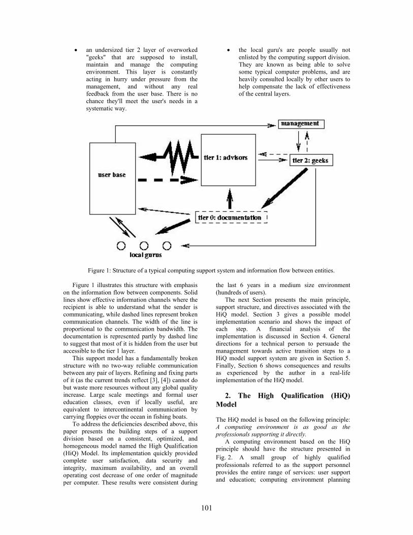
101
• an undersized tier 2 layer of overworked "geeks" that are supposed to install, maintain and manage the computing environment. This layer is constantly acting in hurry under pressure from the management, and without any real feedback from the user base. There is no chance they'll meet the user's needs in a systematic way.
• the local guru's are people usually not enlisted by the computing support division. They are known as being able to solve some typical computer problems, and are heavily consulted locally by other users to help compensate the lack of effectiveness of the central layers.
Figure 1: Structure of a typical computing support system and information flow between entities.
Figure 1 illustrates this structure with emphasis on the information flow between components. Solid lines show effective information channels where the recipient is able to understand what the sender is communicating, while dashed lines represent broken communication channels. The width of the line is proportional to the communication bandwidth. The documentation is represented partly by dashed line to suggest that most of it is hidden from the user but accessible to the tier 1 layer.
This support model has a fundamentally broken structure with no two-way reliable communication between any pair of layers. Refining and fixing parts of it (as the current trends reflect [3], [4]) cannot do but waste more resources without any global quality increase. Large scale meetings and formal user education classes, even if locally useful, are equivalent to intercontinental communication by carrying floppies over the ocean in fishing boats.
To address the deficiencies described above, this paper presents the building steps of a support division based on a consistent, optimized, and homogeneous model named the High Qualification (HiQ) Model. Its implementation quickly provided complete user satisfaction, data security and integrity, maximum availability, and an overall operating cost decrease of one order of magnitude per computer. These results were consistent during
the last 6 years in a medium size environment (hundreds of users).
The next Section presents the main principle, support structure, and directives associated with the HiQ model. Section 3 gives a possible model implementation scenario and shows the impact of each step. A financial analysis of the implementation is discussed in Section 4. General directions for a technical person to persuade the management towards active transition steps to a HiQ model support system are given in Section 5. Finally, Section 6 shows consequences and results as experienced by the author in a real-life implementation of the HiQ model.
2. The High Qualification (HiQ)
Model
The HiQ model is based on the following principle: A computing environment is as good as the professionals supporting it directly.
A computing environment based on the HiQ principle should have the structure presented in Fig. 2. A small group of highly qualified professionals referred to as the support personnel provides the entire range of services: user support and education; computing environment planning

102
and design; software administration; hardware maintenance. The documentation becomes structured and is available/advertised to the entire user community. Strong unrestricted communication
between support personnel and users is maintained for good personalized service and feedback. Fluent two-way communication with the management is established for flexibility and efficiency.
Figure 2: Structure of a computing environment based on the HiQ model.
Here are the main directives that will lead to the implementation of the HiQ principle:
1. The user support and advice should be provided directly by the most qualified support professional immediately available. Users should communicate with the same personnel that configure and maintain their computers, without intermediaries. This inspires trust to users and shortens the service time by fast diagnosis and sharp solutions.
2. The support professional should take the time to logically explain to the user all the steps needed to address the problem. The best time to do user education is during support calls. A completely explained solution to a problem avoids repeated calls for the same or slightly different issues, unclogging the support system. Other consequences are: the user develops a closer relation to the support personnel and the perception of satisfaction increases, users get efficiently educated and will shortly learn how to solve most of the problems by themselves, and the support team understands the particular needs and preferences of every user, so personalized service can be provided easily.
3. Rigid arbitrary rules, as what is "supported" and what is forbidden to the user should not be imposed by any means. No computer related problem with publicly documented solution is off limits to a qualified professional. This gives the shine to the support process. A solved exotic problem will always make the user tell others how happy he is and how good the support is. The overhead to the support system imposed by exotic problems is very small as they rarely appear, and can be solved by a fast documentation round that cannot hurt after all. Even more, today's exotic
problems are tomorrow's trends, so they contribute to keep the support personnel in top shape and current to the newest developments. The limitations and inconvenience produced by a "support" list is unacceptable for the user and shadows the image of the support system.
4. Every user's problem should be solved (or begin to be solved) as it is communicated (i.e. now). This cannot happen immediately in a system transitioning from the old fashioned overloaded support model, but will soon catch up as the frequency of complaints and problems will decrease.
5. The user should have access to a computer system installed and configured by professionals. The user should be encouraged to ask for qualified help when new software is needed. The software should be consistent, functional, fully-featured, customized for the user's needs, robust to user mistakes, and remotely upgradeable. This implies a large amount of polish, additions, security adjustments, reconfigurations, and consistency checks on the original vendor software. The goal can be achieved in a very productive manner using Open Source Software (OSS) that comes in fully featured packages that can be installed together with all the upgrades, changes, customization, in one step (including automatic drivers detection and configuration). OSS offers the same or better functionality than most low-to-midlevel commercial software (see also [5], [6]), without license fees and other restrictions.
6. The computers to be managed should be based on a minimum number of hardware platforms, with uniform software distribution. This imply frequent (at least once a month) software upgrades. A

103
consequence of this process is having the most up-to-date patches and the most recent software on all computers, i.e. no security concerns, no missing features. To implement such an upgrade program, the practical solution points again to OSS deployment that allows computers to be managed remotely and automatically without any interference with the user's work (no reboots, no strange behavior in most of the cases). However, we recommend against using the automatic upgrades over the network offered by software vendors. These upgrades work relatively well for standard (home) systems, but for our "consistent, functional, fully-featured, and customized" software, automatic upgrades may be destructive.
7. Do not let computers age on users’ desks. Users always need new(er), faster, nicer computers to keep them enthusiastic. Normal aging is determined by:
• software decay - the computer seems to become slower and slower, the same amount of information take more and more disk space (process specific to the Windows family of operating systems). Refresh by reinstalling - very expensive process because it cannot be made fully automatic.
• speed decrease - the computer seems to be slower and slower, applications quit working. Comes with software upgrades - newer software is slower (specific to the commercial software). Often purchase of new hardware is necessary.
• hardware decay - noise level increases, keyboards and mice become sticky, image fades away, files get corrupted. As any other machine, computers need periodic maintenance: fans, keyboards, mice should be changed, dust should be cleaned, disks should be refreshed. Doing hardware maintenance at least every other year and knowing that different components have different needs and lifetimes, can double the useful life of a computer.
Anti-aging fight is heavy on budgets, but not doing it is much more expensive. Here are tricks to economically keep systems young and users happy:
• each maintenance should bring a newer computer on the user's desk. This can be done knowing everybody’s computing needs and wisely rotating the computers.
• OSS should be used on most of the computers. The same computer will be perceived as unacceptable slow after an average lifetime of about 3-4 years if commercial software is used, or 6-7 years if OSS is used.
• brand-name desktops should be avoided. PC vendors do not manufacture the parts inside the box, but can tamper with them.
Big vendors slightly customize the hardware to make it incompatible with standard parts and to be able to charge more for most upgrades and replacements which can be bought only from them. Generic (but established) vendors usually sell standard hardware, offer larger configuration freedom, have no brand-name tax, and will even sell systems without the operating system installed (and of course no Microsoft tax).
• the hardware maintenance and the repairs of standard equipment should be done by the support personnel (unless there are warranty issues). No proprietary equipment (e.g. printers) should be considered unless a good local supplier of service and replacement parts is singled out.
• PC hardware components without OSS support are usually a signal of poor quality or inflated price. The purchase of such components is wasted money even if there is no intention to use them in OSS environments.
8. No downtime is acceptable. Computers shouldn't ever get stuck or need rebooting for unplanned reasons. Rebooting and reinstalling are unacceptable time and resource wasting practices that may work for the home user but should have no room in a business environment. Computers should be stopped only for regular planned maintenance (not more than 1-2 hours a year). Critical servers should have redundant configurations such that the uptime is practically 100% in most conditions. A key to achieve such results is OSS, which is stable, immune to viruses and worms, and hardware friendly [5]. 9. The support personnel should participate in R&D activities. These people should have a perspective academic view over their field. Funds should be available to them for experiments on hardware and software. Keeping the support professionals hands-on involved with new technologies should offer the useful knowledge otherwise un-achievable. Much more funds will be wasted on uninspired equipment or software purchase if this aspect is overlooked.
10. No more expensive consultants. The support professionals should be able to solve all the local computer problems if public documentation is available. A proprietary solution that is not properly serviced and maintained by the manufacturer and the costs are not entirely disclosed up-front, should be dumped. It is always possible to reformulate the problem in terms of open standards and OSS.
The next Section presents a possible model implementation scenario and shows the implications of each step.

104
3. HiQ Model Implementation
The implementation of the model depends a lot on the organization structure, on the number and geographic distribution of the users, and on the current environment. Following is a set of steps to build a computer environment based on the HiQ model by gradual transitioning from a classical structure. These steps were suggested by our hands-on experience. Remarkable is that the computing budget starts decreasing and the user satisfaction jumps up quite shortly after the beginning of the transition process.
First step: gradually start building the HiQ task force. Start replacing every three "tier 1" advisors with one qualified professional paid 2.5 times as much as an advisor. Look for people with a graduate degree and work experience. Advertise the new "task force" to users as a contact for special or urgent problems. Plan to end up with one qualified professional for every 200 computers running OSS or for every 50 computers running commercial software.
Second step: start building custom software distributions matching the local needs and activities. After 2-3 months, the HiQ people have already a perspective view about what's wrong and what's needed. Their activity already relieved much of the pressure on the old help system and increased users’ confidence. They should be able to start building an OSS distribution that will match the environment. This is an experimental job that will take several months and the participation of some of the most advanced users (the old local gurus) for feedback. Once an acceptable software distribution was created and the general interest features needed by most of the users are covered, it is time for the big deployment.
Third step: start encouraging users to migrate to a standard hardware platform running the newly developed software distribution. This is a delicate step that should be done with diplomacy. The user should invest time to learn the new system and should be convinced that it is worth the effort. From our experience, it should take about one year to have half of the users migrated. There are several friendly forces that can help even the most stubborn users join the new environment:
• features: the new software distribution being more polished should look better, should feel faster, should have more services, more features, and less bugs than what most people currently use. Everybody becomes sensitive if their neighbor has a better behaving computer.
• hardware: early adopters can be compensated with a new computer.
• funding: gently share with reluctant users higher costs of running a system that is not the recommended platform.
Fourth step: consolidate the environment. Once about 75% of the users are migrated to the new environment and are happy with their new computing experience, it is time to decommission the old structures (if not already done so) and to fully deploy the new HiQ environment. The time for details that matter arrived: good documentation of software and services, systematic user education, R&D programs. The focal points are:
• good communication between support personnel and users is fundamental. Since the help pressure from users is much lower now, new ways should be found to keep the communication alive. Users should be encouraged to discuss with the support personnel not only problems, but future plans, equipment issues, new developments, etc.
• invest in the support personnel, they're now great assets. The support personnel are professionals, so they need intellectual satisfaction. They should participate in research projects, conferences, and other activities where their work is recognized by peers.
Fifth step: plan for the future. At this point a nice base of satisfied users should be clustered around a small but efficient collective of professionals that maintain a fully-featured economical and secure computing environment. Plan for (even small) disasters and take the necessary steps: distributed backup systems, UPSes, redundant servers, spare parts for exotic or older computers. The objective is that if a small-to-moderate disaster happens, the recovery time to minimal levels of service should be of several hours in the worst case. A typical computer hardware crash (shouldn't be typical any more, since regular maintenance is done) can be completely recovered in less than one hour.
After all these steps and about 2 years of transition one can finally talk about a rounded computing environment, secure, economical to operate, and joyful to use.
What should happen to the old structures? The tier 1 advisors, as minimum wagers, are typically a volatile workforce that should fade away if no new hiring is made. Many of the tier 2 geeks may be used as new support professionals after they are re-qualified. Their hands-on experience is very useful, but an academic education which gives the perspective view of the field, the ability to effectively communicate, and the skills to educate the users is crucial. The "local gurus" loose their role as supplementary gray-zone support people, but become very valuable for educated feedback regarding hardware and software needs and quality of services.

105
The next Section makes a financial analysis of the implementation and discusses the transition costs.
4. Operating Costs and Transition
Cost Recovery
Operating costs of the new computing environment [7] may be up to one order of magnitude lower than the amount needed by the old structure, depending on particular requirements and compromises.
Here is an itemized analysis based on the HiQ model implementation directives:
1. The total salary fund for support personnel is expected to slightly decrease or remain constant, as higher wages per professional are compensated by a reduction of the structure size.
2. Software licensing costs that are typically 3-5 times the price of hardware during the life of a computer are reduced to nothing by using OSS.
3. Hardware costs can be reduced as follows: • about 30% off the general purpose
computer expenses by maintenance and by increasing the hardware's useful life using OSS (maintenance costs of 20% were subtracted);
• about 20% off the general purpose computer expenses by optimal purchasing policy (generic PCs with no pre-installed software);
• about 80% off the proprietary computer and specialized equipment expenses by mi-grating from proprietary hardware to open platforms (PC) and by in-house building of most of the advanced systems (dedicated servers, RAID arrays, low traffic routers);
• about 30% off the large scale computer (and eventual commercial software) expenses by avoiding uninspired purchases (testing and research funds of 20% were subtracted).
4. User education costs are expected to slightly decrease. Meetings and talks should be maintained for their social value. However, no paid external trainer is necessary any more. The bulk of the training is done during the support process.
5. Training of the support professionals is done automatically in the support process at no additional cost, and by R&D projects that had the expenses included above.
6. Repair expenses are reduced to the replacement parts, which is less than half from the total cost. Repair frequency is reduced by one order of magnitude through periodic maintenance. So the global cost of repairs is reduced by about 95%. Most of the original repair expenses were absorbed in the maintenance that is amortized by increasing the hardware's life.
7. Consulting expenses are completely eliminated if OSS is used. Software sources give the
support professionals the opportunity to solve any potential problems and to customize the software even for exotic user requirements.
8. Server downtime and crashes disappear completely. Together with them, gone is the main reason for loss of business and of sensitive data for most companies.
9. If OSS is used, computer downtime (rebooting, reinstalling, upgrading) is reduced by several orders of magnitude, greatly improving the overall productivity of the users. The frustration caused by computers not working properly is gone.
10. Security expenses as encryption and anti-virus software are not needed any more. Open source operating systems (e.g. Linux) come with good encryption software, no backdoors, and practically no virus sensitivity. The network and the computers become as safe as they can be, without spending an extra penny on it.
Some possible transition scenarios may imply a temporary bump in funding needs at the beginning of the process. This should happen especially when the new structure is built before the old one is faded out, as needed by a faster transition than described in Section 3. In environments where the wages are not important compared with the total computing expenses, the bump shouldn't be visible even if the transition is fast. Otherwise, it can be absorbed effectively by performing in-house repairs and dropping most of the external consulting. Such activities can be started immediately by the new support personnel without any transition period.
A serious cost analysis article with relevant numbers and in-depth understanding of the computing environment is offered by [8].
The next Section presents general directions for a technical person to persuade the management towards active transition steps to a HiQ model support system.
5. Work with the Management
Typically, the change of the computing support model is suggested to the management by a technical person or a small group of users having hard times doing their jobs because of the low quality of the existing computing environment. This section is written in support of such an initiative and should offer basic advice about how to persuade management to start working on a change that may look radical and risky from their point of view.
Management has their way of conducting business that is statistically correct and opposes radical changes over short periods of time. That's good policy. Fast action can miss critical details that make the difference between a good project and a failed implementation. Even technical management totally convinced that this is the right way to go, will be reluctant and will move slowly. So, as a general rule, do not push and do not antagonize. The
106
idea is new for them, they'll have to get used and sympathize with it.
The first step to convince management that the transition to a new computing support model is necessary is to present the new model and the advantages exposed in the Sections above. If these arguments don't trigger the expected amount of action, here are a few more tricks to help:
• start small: a pilot project may be a good starting point;
• pick the right person: talk to management that can understand technical arguments;
• be concrete: name names, come up with a plan suitable for the local environment;
• use the right arguments on the right people: most management is always happy to make employees happier and more productive without increasing spending;
• use opportunities: a casual conversation down the hall has much more chances to be considered than a formal request made during an official meeting.
The next Section shows results obtained by the author in a real-life implementation of the HiQ model.
6. Some Real-Life Results
The HiQ model was built extracting the essence of the author's more than 6 years experience in a medium sized Department. From an outside observer’s perspective, the transition time from a "desperate" to an "outstanding" state of the computing environment took more than 1 year. However, by contrast with the old service level, the quality improvement appeared spectacular to users and management almost immediately.
The budget for computing equipment and maintenance is still less than half the amount of the year before the transition was started, while the number of computers increased by more than 5 times.
The implementation of the HiQ model had the following consequences: no unscheduled server downtime, no data loss, no surprise security breaches (including viruses, worms, or human perpetrators), for the last 5 years. This happens as the full range of network services and a very large spectrum of applications are offered to the users. More than 95% of the serviced computers are running the Linux operating system at the present moment. The OSS character of Linux has a large merit in maintaining the high quality and the low cost of the computing environment. However, without a HiQ structure of support personnel, there is no way to take advantage of the OSS advantages.
7. Conclusions
A good computing support service, as the one based on the HiQ model, can substantially improve data security, server uptime, number of features and services, productivity and reliability of the computing environment, and user satisfaction. At the same time, the budget for computing can be substantially reduced.
The HiQ model implementation is systematically described. Implementation details and cost analysis that support the author’s claims are offered. Data and solutions were derived from years of hands-on experience. Computing environment support based on the HiO model can be gradually implemented without an important financial or administrative overhead on a time scale of 1-2 years.
The HiQ model for supporting a computing environment is based on a consistent set of ideas and principles, with emphasis on using the most qualified people for the job, optimizing communication between different components of the environment, and getting the best performance/price ratio out of the funds.
References [1] "A support model for the Information
Technology Department in the University of Canterbury", by Information Technology at University of Canterbury, http://www.it.canterbury.ac.nz/support/supportmodel.htm
[2] "The ITS Four Tiered Support Model", by Information Technology Services at University of Colorado, http://www.colorado.edu/its/about/tiermodel.html
[3] Polley A. McLure, John W. Smith, and Toby D. Sitko, "The Crisis in Information Technology Support: Has Our Cur-rent Model Reached Its Limit?", CAUSE Professional Paper Series, No 16, http://www.educause.edu/ir/library/html/pub3016/16index.html
[4] Richard M. Kesner, "Developing an Information Technology Support Model for Higher Education", CAUSE/EFFECT,Volume 20, Number 2, Summer 1997, pp. 24-30, http://www.educause.edu/ir/library/html/cem9725.html
[5] David A. Wheeler, "Why Open Source Software / Free Software (OSS/FS)? Look at the Numbers!”, http://www.dwheeler.com/oss_fs_why.html
[6] Erick Schonfeld, "Linux for the Rest of Us", Business 2.0 Magazine, Nov 2002, http://business2.com/articles/mag/0,1640,44531,FF.html

107
[7] "TCO models & approaches", COMPAQ Document, http://h18000.www1.hp.com/tco/models.html
[8] Paul Murphy, "A strategic comparison of Windows vs. Unix", LinuxWorld, Oct 18, 2001, http://www.linuxworld.com/sitestories/2001/1018.tco.html

108
A Rule Cache for iptables in Linux
Adrian Petru Mierlutiu “Politehnica” University, Timisoara
Abstract
iptables run on a low-end Linux box is a very
common solution to firewalling, especially for academic and educational environments because of it's low cost, either on workstations for local protection or for routers and bastion hosts. Complex rule-sets are common practice, which in combination with a relatively high-speed network connection might result in performance degradation. In this paper we propose a caching mechanism for the firewall rules, for improving performance as measured in latency, throughput and system load. We describe our implementation of the rule cache, and how firewall semantics is maintained unaltered. A preliminary performance evaluation is also presented. Finally, we show the benefits of employing such a rule caching, and discuss other possible usages. 1. Introduction
The need to connect computers together in networks needs not be discussed. Also, connecting such networks (or individual stations) to the Internet is now a must. Unfortunately, this comes with side effects: we expose our computers to a large set of attacks and attackers. We can classify these attacks in vulnerabilities of software that we run on the computer (attacks commonly known as exploits), and denial of service attacks (such as floods of different kinds). Software vulnerabilities can be addressed either by detecting and patching such problems, or by denying access (especially from the network) to the programs. While the first method should be desirable, it is not always possible to detect and correct bugs, or deploy and install patches or service packs in a timely manner (one step in front of the attacker). Therefore one should allow access to
programs running on a station only to trusted parties, i.e. hosts from the local network. Floods and other types of denial of service attacks have to be stopped generally by active components of the network, as close to the source of the attack as possible. This has two components: one that detects the attack and one that must stop it. To partially address these problems, often a firewall is employed. Firewall technology permits the enforcement of a security policy over the network traffic that crosses the boundary of a protected network, or domain [8]. Such a firewall may have different functions [8][5]: audit, authentication, integrity checking and access control. We will refer to this last function, as packet filtering, a name more commonly used. A packet filter has to permit or deny network traffic, according to the security policy. Packet filters are an effective way to protect hosts and networks and although they are not protecting against all attacks, a large part of them can be eliminated this way. Packet filters cannot by themselves detect floods, but they may stop them if the security policy is properly adapted. Also, packet filters cannot detect data-driven attacks like viruses downloaded in e-mails [8]. But they can screen applications on hosts and networks from outsiders, eliminate unwanted traffic, prohibit attacks sourcing from the local network or host, and so on. One other drawback of packet filters is obtrusiveness: generally the more we filter, the more we deny access to services from users [12]. One solution is stateful inspection (see for example [3], or HOWTOs on http://www.netfilter.org). Packet filtering can be done at different points in a network (see figure 1 a, b). A common topology is to filter at the entry point of the network we want to protect (typically a router), thus considering hosts on the same network as trusted. This may work well in many trusted environments, but may as well not be appropriate for others, as described below.
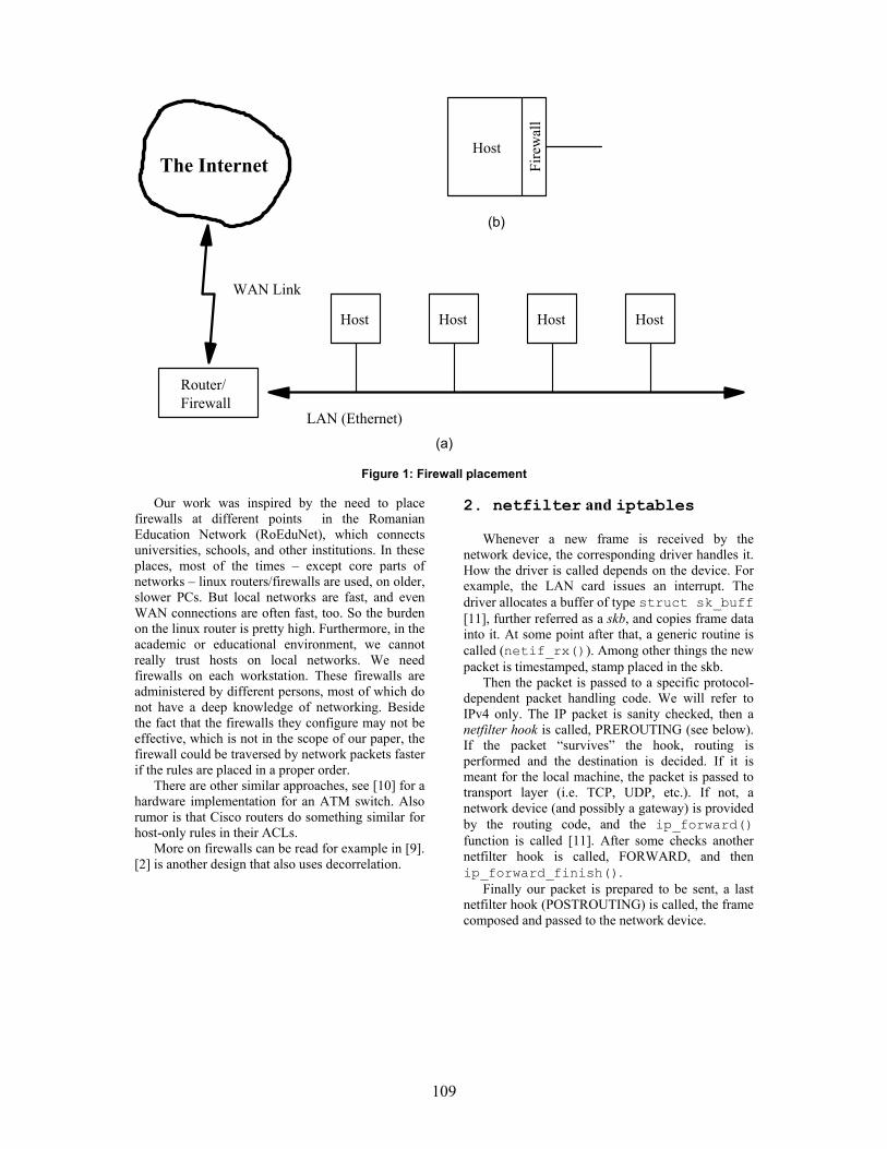
109
The Internet
FirewallRouter/
Host Host HostHost
Fire
wal
l
Host
(a)
WAN Link
LAN (Ethernet)
(b)
Figure 1: Firewall placement
Our work was inspired by the need to place
firewalls at different points in the Romanian Education Network (RoEduNet), which connects universities, schools, and other institutions. In these places, most of the times – except core parts of networks – linux routers/firewalls are used, on older, slower PCs. But local networks are fast, and even WAN connections are often fast, too. So the burden on the linux router is pretty high. Furthermore, in the academic or educational environment, we cannot really trust hosts on local networks. We need firewalls on each workstation. These firewalls are administered by different persons, most of which do not have a deep knowledge of networking. Beside the fact that the firewalls they configure may not be effective, which is not in the scope of our paper, the firewall could be traversed by network packets faster if the rules are placed in a proper order.
There are other similar approaches, see [10] for a hardware implementation for an ATM switch. Also rumor is that Cisco routers do something similar for host-only rules in their ACLs.
More on firewalls can be read for example in [9]. [2] is another design that also uses decorrelation.
2. netfilter and iptables
Whenever a new frame is received by the network device, the corresponding driver handles it. How the driver is called depends on the device. For example, the LAN card issues an interrupt. The driver allocates a buffer of type struct sk_buff [11], further referred as a skb, and copies frame data into it. At some point after that, a generic routine is called (netif_rx()). Among other things the new packet is timestamped, stamp placed in the skb.
Then the packet is passed to a specific protocol-dependent packet handling code. We will refer to IPv4 only. The IP packet is sanity checked, then a netfilter hook is called, PREROUTING (see below). If the packet “survives” the hook, routing is performed and the destination is decided. If it is meant for the local machine, the packet is passed to transport layer (i.e. TCP, UDP, etc.). If not, a network device (and possibly a gateway) is provided by the routing code, and the ip_forward() function is called [11]. After some checks another netfilter hook is called, FORWARD, and then ip_forward_finish().
Finally our packet is prepared to be sent, a last netfilter hook (POSTROUTING) is called, the frame composed and passed to the network device.

110
PRE ROUTING FWD POST
OUTIN
Local Processes Local Processes
Figure 2: The netfilter hooks
The netfilter is an infrastructure that consists of hooks in the path of packets going through the network stack (figure 2). Kernel parts or modules can register functions to be called at each such hook [6]. Iptables is built upon this framework, and permits registration of tables that contain rules, grouped in chains. Currently this is used for achieving three objectives, each with its own table: filter, nat and mangle, used for packet filtering, network address translation and general packet mangling, respectively.
The filter table contains three chains: INPUT, FORWARD and OUTPUT, hooked on the IN, FWD and OUT hooks. Packets locally created pass through the OUTPUT chain. Packets destined to the station are checked by rules in the INPUT chain. Traffic that enters one network interface and is routed to another has to pass through the FORWARD chain. Each rule in a chain consists of a number of matches1 and a target. The matches may check for values in the different protocol header fields such as source address, destination port, TTL,etc., stateful information, or other things. Targets decide the fate of the packet, and are typically ACCEPT or DROP, but not only. Iptables is very extensible, so new matches (like owner, ToS) or targets (like REJECT) can be and are easily written.
Without loss of generality, we will take into consideration only basic matches: the protocol that the IP packet carries (that we will again consider to be either tcp or udp), source and destination addresses (network address/mask style) and source and destination port; and only the two very common targets ACCEPT and DROP.
Rules are checked beginning with the first in a chain. If all the matches of a rule are true (the packet conforms to them) than the action dictated by the target is taken. Otherwise the next rule in the chain is tried. Finally, if no rule matches, the default 1 Which we assimilate with the selectors from [7].
policy of the chain will apply, which is a target. For simplicity this may be considered as a rule matching any packet and with the target set to the default policy. In this way, we may treat the default policy and rules uniformly.
Below is an example of a very simple (and silly) INPUT chain of the filter table: -p tcp --dport 1-1023 -j DROP -s 10.0.0.1/32 -p udp --sport 53 -j ACCEPT -p udp -j DROP -p tcp -j ACCEPT
In this syntax, wherever a match is omitted, it is assumed that it exists, matching the whole range. So the first rule really looks like: -p tcp -s 0.0.0.0/0 -d 0.0.0.0/0 --sport 1-65535 --dport 1-1023 -j DROP
The first rule tells the filter to drop all the packets which carry tcp traffic with destination ports ranging from 1 to 1023. The second allows incoming udp traffic from the name server 10.0.0.1. The third drops all other udp traffic. Finally the fourth accepts all tcp traffic.
The rules, chains and tables are maintained by the system administrator with the iptables command. This command in turn uses the libiptc library, which provides functions for manipulating the data structures corresponding to the tables from userspace. Rules may be created, added or deleted, counters may be read or zeroed. 3. Caching the Rules
As we saw in the previous sections, all incoming, outgoing or passing through packets are checked against the rules in a chain from the filter table. Several rules are checked before the appropriate one is met, when the packet is either allowed or discarded (other actions may be taken, but that is irrelevant for this paper). If the system administrator

111
is not careful, many packets may be matched by rules in the bottom of the chain. This could lead to performance degradation, when there are lots of rules, or when the traffic rate is high. Examining the packet counts, the system administrator could tell if it would be better to move one or more of the rules in the front of the chain. Unfortunately, it often happens that the traffic pattern changes rapidly in time, and this moving of rules becomes impractical.
For such a situation we propose a system that caches the most frequently used rules, so that the more likely to be matched rules are checked first. There are two important problems with this arrangement. First, rules in a chain may be correlated, so that their order is relevant. Second, we have to decide when is it worth to cache a rule. 3.1. Cache Implementation The cache is implemented as a new chain in the iptables filter table, for each built-in chain (INPUT, OUTPUT and FORWARD) named cache_input, cache_output and cache_forward2respectively. To define new chains is a normal facility of iptables. First rule in each of INPUT, OUTPUT and FORWARD chains will have an empty match and will jump to the corresponding cache chain, so all packets will first visit the cache, then, if they weren't matched by any rule in the cache, the rest of the chain.
The implementation we describe is not a full-blown one, it misses certain things. If there are also other chains defined by the system administrator, they are not cached.
The rules from the cache chains are updated, as those in the other chains, by a userspace program. The difference is that while ``normal'' chains are managed by the iptables command by a human, our cache rules are inserted and deleted automatically by a daemon3. This does not mean that they could not be manipulated as well with the iptables program.
The daemon program, which we call crud (cache rule update daemon), comes to life at configurable length intervals. It analyses the statistics of rules usage, and if notable differences from the previous interval are detected, computes the rules that should be placed in the cache, calculates the benefits the system would obtain from placing those rules in the cache and if it is worth it, updates the cache chains accordingly.
At load time, or when a SIGHUP signal is sent to it, crud loads in turn the rules in each chain from the filter table, and calls the decorrelation function (see section 3.2). We store the rules in a
2 We used the de-facto convention that user defined chains are named with lowercase characters. 3 A UNIX daemon is a process running in the background, without a controlling terminal.
linked list whose elements correspond to the original rules and have pointers to the set of decorrelated rules, like this: original rules: r1->r2->r3->... decorrelated rules: (r1->d1.1,d1.2)-> (r2->d2.1)->(r3->d3.1,d3.2,d3.3)->...
If, say, rule r2 is to be put in the cache, then, to keep the semantics of the firewall consistent, we will have to cache instead of r2 the decorrelated rules corresponding to r2. It might happen that not all the decorrelated rules will get frequent hits in the cache. But this is the same problem for any independent rule in our cache.
At a given point one rule in the cache might not be used often enough. To decide which rules to discard, we estimate the amount of time packets would spend going through the firewall with and without having that rule in the cache, in the same manner we do it for rules to be brought in the cache. Then we decide, based on an experimentally chosen value, if the rule should stay (or should be put) in the cache. See section 3.3 for details.
We need to discard unused rules from the cache, as the packets that will not be matched by cached rules still have to pass through the cache, being delayed. So we want to keep the cache small. 3.2. Decorrelation of Rules
We will use some of the terminology in [7] in this section, for clarity. We will call the matches of a rule selectors, to remove the ambiguity between matches of a rule and the fact that a rule matches. With this, a rule matches a packet when all the selectors are true.
There is a value stored with all the rules in the iptables, called nfcache, which is a summary of the selectors used by that rule. Each bit represents a selector type, like source address, destination port, and so on. If the bit is set, than the rule has a corresponding selector defined. If not, the rule will match any value corresponding to that selector. This results in a possible redundancy. It is the same thing if the bit corresponding to the source address selector is 0, or the source address selector is “0.0.0.0/0”, that is, matches the whole range of possible values. So when we decorrelate the rules, first we make sure that if we have selectors that match the whole range, the corresponding nfcache bit is null.
The algorithm we use to decorrelate the rules was described by Sanchez and Condell in [7]. We present it here shortly, with adaptation to our situation.
Two rules are correlated if there can be packets that would be matched by both rules. That is, the set of ranges defined by the selectors of the two rules overlap. We observe that although two rules may be correlated, if their target is the same, it does not

112
matter which is matched first. If two rules are correlated but their target is the same, we call them soft correlated, and state that we do not need to decorrelate two soft correlated rules, since the effect would be the same anyway. If the targets differ, and the rules are correlated (hard, or strong correlation), then we need to decorrelate them. This is a first difference from the original algorithm. The second is that we need to keep a list of decorrelated rules for each one of the rules, and these need to be decorrelated from all other rules, as we will actually not use them in the real firewall just when we bring the rule in the cache.
For each rule ri: 1. Check if ri is correlated with any rule rj, j ≠ i
a. calculate bitwise AND of the nfcache values of the two rules, vij. If the result is null, and at least one of the rules has a non-zero nfcache, then the rules are correlated b. for each selector corresponding to a 1 bit in vij, check if the ranges overlap; if at least one of them do not overlap, the rules are not correlated c. otherwise, the rules are correlated
If the rule is correlated with others, mark the rules which are correlated with it. If it is not, choose next rule and repeat this step. 2. Proceed with the algorithm from [7], with the difference that we use the marked rules in the previous step for the set U. This is because we need the decorrelated rules of one rule against the others, not a set of decorrelated rules to be used instead of the original ones. 3. Memorize the decorrelated rules as explained in the previous section.
3.3. Caching Decision
We have to decide when and what rule to cache. If we put a rule in the cache, we expect to have some benefits. These benefits we will measure as being the difference between of the time a set of packets would spend through the firewall without and with the cached rule or rules. That is, we bring a rule in the cache if we expect the latency will decrease.
Let there be an ordered set R of rules ri, where i is in an ordered set SR = 1, 2, 3, …,NR. For simplicity, we suppose the time to evaluate each rule in the set is approximately the same, t. Given a set of network packets P, the total time the system will use to pass P through the rules in R will depend on how many packets will be matched by each particular rule. We can measure this, so that each time a packet is matched by a rule ri, a counter ni is increased4. Now the time for the entire set of packets P will be
4 This is equivalent with knowing the relative frequencies for each rule
∑∈
=RSi
iR intT **'
(1) because if a packet is matched be the rule ri then it passed through i other rules. As t is a constant, we will ignore it for now on, keeping in mind that all the results will be proportional with t.
∑∈
=RSi
iR inT *
(2)
The cache is an ordered set of rules, C, initially empty. Suppose we add rules r2 and r6 to the cache, so C = c1, c2 , and c1 = r2, c2 = r6. We define ϕ(i) a mapping of i ∈ SR that gives the position in the cache of the rule ri or 0 if it is not in the cache. With this, ϕ(2) = 1, ϕ(6) = 2.
If we suppose no cache hit will occur (which is not the case, unless ni for rule ri in the cache is zero), then the latency will become
∑
∑∑∑
∈
∈∈∈
+=
+=+=
R
RRR
SiiCR
SiiC
Sii
SiCim
nNT
nNinNinT
*
**)(*
(3)
where NC is the number of cached rules. Of course, ni packets will match for rule ri in the cache. As in (2), the total time for the rules in the cache will be
∑∈
=CSi
iC inT )(*ϕ
(4)
where SC is the set indexes from SR that correspond to the rules in the cache (for our example, SC = 2, 6). The packets that where matched in the cache will not be matched in R, so we'll have to subtract the time these packets would have spent if not matched from Tm
∑∈
+=CSi
Cis NinT )(*
(5)
From (3), (4) and (5) results the total latency
∑∑∈∈
−(++
=−+=
CCR Sii
SSiiCR
sCm
iinnNTTTTT
))(**\
ϕ
(6)
What we gained is the difference between (2) and (6), which should be greater then a positive

113
value p (since if we gain 1 microsecond for a thousand packets, maybe it's not worth it).
Suppose again that the cache is empty, and then we put rj in the cache. The difference in the latency will be
))((**\
jjnjnNTjSi
iCD
R
−−−= ∑∈
ϕ
(7)
As this is the first rule in cache, ϕ(j) will be 1, so
)1(*\
jnjnTjSi
iDR
−−−= ∑∈
(8)
which should be greater than p:
∑∈
+>−\
)1(*jSi
ij
R
npjn
(9)
We always insert a rule as the first in cache, then sort them at each update interval in the inverse order of packet counts. This is possible due to the fact that the rules in the cache are decorrelated.
The discussion above is valid in the case the rules in R are not correlated. If they are, first we should decorrelate them. The problem is we know the frequencies ni for the rules effectively existing in the firewall, and not for the decorrelated rules. In this case the math is done so that NC will be the total number of rules in the cache after adding the decorrelated rules corresponding to ri, and TC will be calculated as if the last decorrelated rule would have the relative frequency ni and the previous ones would have zero, considering the worst case. 4. Performance Evaluation
We show in this section some experimental results. The evaluation is not thorough; its purpose is to give us an idea of the benefits of our caching mechanism.
To be able to measure latency so it is as little influenced by external factors, we arrange for an experimental network of three hosts, unconnected to any other host. One of them is just a target or destination (machine D), one will generate traffic (machine G) and the third (machine M), on which the measurement takes place, forwards traffic. Machine M has two FastEthernet network cards, one connected to G and one to station D. As we saw in section 2, each packet is timestamped at its arrival.
We have modified the IP stack so that immediately\footnotealmost immediately, actually after the FWD hook, the time elapsed since the packet was timestamped is summed to a total value FET (forward elapsed timer). This value is
accessible through a new system call that allows us to zero the FET or read it. Before a set of packets (a data set) is generated by G, FET is zeroed. After the destination D receives them, FET is read. No other traffic then that that is generated by G passes through M.
We used two different PC workstations for machine M. M1 is a Celeron at 600Mhz with 256MB RAM, and M2 is a Pentium at 100Mhz with 48MB RAM. We measure the FET for 10, 50 and 100 rules in the FORWARD chain (the only chain the packets will pass through) of the filter table. The data sets consist of UDP packets having the destination D, with random source and random ports. The load of the packet (data) is 16 bytes, thus resulting in 34 byte packets. The first data set has 10000 packets sent at 500pps (packets per second), and the second data set has 20000 packets sent at 1000pps. The numbers represent the total latency for all the packets in a data set, in milliseconds.
Rules in chain Data set
Test number 10 50 100
1 45.44 55.82 71.46 2 45.68 55.68 71.33
1
3 45.79 55.74 71.63 1 90.48 112.54 139.69 2 90.54 111.85 139.11
2
3 90.87 110.59 138.95 Table 1: Latencies for machine M1 without
caching
Rules in chain Data set
Test number 10 50 100
1 40.09 40.03 40.11 2 40.09 40.00 39.76
1
3 40.13 40.08 40.17 1 79.02 79.02 80.72 2 79.79 80.17 78.86
2
3 79.46 79.48 78.76 Table 1: Latencies for machine M1 with caching
Rules in chain Data
set Test
number 10 50 100 1 266.82 399.34 600.98 2 262.93 384.50 602.74
1
3 256.88 397.21 601.48 1 533.84 799.12 1021.12 2 537.12 797.36 1031.44
2
3 534.06 802.50 1025.39 Table 1: Latencies for machine M2 without
caching

114
Rules in chain Data
set Test
number 10 50 100 1 225.33 214.10 215.73 2 242.51 224.43 225.89
1
3 232.27 299.48 227.04 1 460.02 488.31 474.48 2 467.66 459.97 475.14
2
3 463.39 477.52 479.60 Table 1: Latencies for machine M2 with caching
As we may see, and as expected, the difference
between the latency without and with caching is linearly dependent with the number of rules and with the traffic rate, for both machines. What is significant to notice is that even for the smaller rates and number of rules, for the slower machine the difference is still large, about 250 ms. 5. Conclusions and Future Work
We have designed and implemented a mechanism to cache certain rules in a firewall chain. From the experimental results, it should be clear that this is worth using on slow machines and where there is a high network traffic rate, with fairly complex firewall rules. The advantages are insignificant for a fast or even normal workstation, with a simple firewall.
The cache we designed might be integrated with a flood detection system, which may throw blocking rules directly in the cache.
A better, faster way to decide when to cache a rule should be developed. It is not important to be very accurate, but much faster then what we described. Also correlation of rules might be based on algorithms described in [1]. The cache could be a special-case, faster matching mechanism then other chains, which could be done like in [1] or [4].
For a working, full implementation, all the possible matches of a rule should be taken into consideration, which is straightforward. Also part of the code could be brought into kernel space. References [1] David Eppstein, S. Muthukrishnan. Internet Packet Filter Management and Rectangle Geometry, Proceedings of the 12th Annual ACM-SIAM Symposium on Discrete Algorithms (SODA 2001), pp. 827-835, Washington D.C., January 2001 [2] Pasi Eronen, Jukka Zitting. An expert system for analyzing firewall rules, Proceedings of the 6th Nordic Workshop on Secure IT Systems, Technical report IMM-TR-2001-14, pp. 100-107, Technical University of Denmark, November 2001 [3] Scott Hazelhurst. A Proposal for Dynamic Access Lists for TCP/IP Packet Filtering,
Proceedings of the South African Institute of Computer Scientists and Information Technologists, September 2001 [4] T. V. Lakshman, D. Stiliadis. High-Speed Policy-based Packet Filtering Using Efficient Multi-dimensional Range Matching, Proceedings of ACM SIGCOMM'98, Vancouver CA, September 1998 [5] Indrek Peri. Firewalls. Security in Distributed Systems, University of Helsinky , November 2000 [6] Rusty Russell, Harald Welte. Linux netfilter Hacking HOWTO, Online at http://www.netfilter.org/documentation/HOWTO/ netfilter-hacking-HOWTO.a4.ps [7] Luis A. Sanchez, Matthew N. Condell. Security policy protocol, IETF Internet Draft draft-ietf-ipsp-spp-01, Online at http://www.ietf.org/proceedings/02mar/I-D/draft-ietf-ipsp-spp-01.txt, Appendix C, January 2002 [8] Christoph L. Schuba, Eugene H. Spafford. A Reference Model for Firewall Technology, Proceedings of the Thirteenth Annual Computer Security Applications Conference, December 1997 [9] Mukesh Singhal, Jun Xu. Logical Firewalls: A Mechanism for Security in Future Networking Environments, The Ohio State University, November 1996, Online at ftp://ftp.cis.ohio-state.edu/pub/tech-report/1996/TR62.ps.gz [10] Mukesh Singhal, Jun Xu. Design and Evaluation of a High-Performance ATM Firewall Switch and Its Applications, IEEE Journal on Selected Areas in Communications, Vol.17, No.6, June 1999 [11] Harald Welte. The journey of a packet through the linux 2.4 network stack, Online at http://gnumonks.org/ftp/pub/doc/packet-journey-2.4.html [12] James M. Westall. A Simple, Configurable, and Adaptive Network Firewall for Linux, Proceedings of 39th Annual ACM Southeast Conference, Athens, Ga., Mar. 2001, pp. 162-168

115
Virtual Campus and “eLearning” at University of Bucharest
Ioan Mihailescu, Bogdan Logofatu, Michaela Logofatu, Luca Boboc-Corcotoi, Marius Munteanu, Alina Munteanu, Mircea Florescu, Cristian Logofatu
University of Bucharest [email protected]
Abstract
This paper aims to present the Virtual Campus designed and implemented at the University of Bucharest as well as the present status of the “eLearning”. These two objectives are included in the general strategy approved by the Senate’s Decision of 11 April 2002, in order to promote the IT&C in education, within our University.
The Virtual Campus was open in July 2002 and was tested by the staff of the Department for Open Distance Learning, Continuing Education and Professional Conversion, CREDIS. Now, the Virtual Campus is currently used by our students, academic and administrative staff, and guests from other universities in Romania and abroad. Meanwhile, the eLearning system was taken into consideration and the first courses designed and produced at CREDIS were the course modules used as learning resources for the training activities focused on the ECDL Certificate.
1. Introduction
The University of Bucharest, one of the oldest in Romania, is confronted with the process of restructuring of the academic and the administrative activities in order to be able to survive in this very competitive and challenging market of education.
One of the most important aspect is the requirement to modernize the educational offer and to adapt this offer to the needs of the society. Romanian society has to be in line with the well known concepts of Information Society and Knowledge Society. That is why, the Senate Board has prepared a strategy that was approved by the University’s Senate. One crucial objective included in this strategy is to promote the IT&C in education. Recently, a survey published on the site of the World Education Market concluded that the most critical policy issues in education today are "the digital divide" (30%) and "the lifelong learning culture" (30%). How our University addresses this issues? This article will present our policy and the results obtained during the academic year 2002/2003 with focus on Virtual Campus and eLearning.
2. IT&C in education The IT&C (Information Technology and
Communication) policy was designed having in mind three objectives:
1. IT&C for All 2. to adapt the activity of the staff and the
institution to the digital requirements 3. to educate the future specialists for the IT jobs
and market. Having the objective to raise the level of
knowledge about Information Technology and increase the level of competence in using personal computers and common computer applications for all the students and staff of the University, we decided to apply and to become ECDL Test Centre (http://ecdl.credis.ro).
Endorsed by many Governments, learning
institutions and leading corporates in Europe and around the world, ECDL/ICDL has become the leading formal computer skills certification sought by students, workers, employers and the general public (http://www.icdl.org). In education, the ECDL programme in Europe in particular has been evaluated and approved by many Governments as a policy framework for the development of Information Technology in schools. The programme has been adopted to prepare school students for their participation in the Information Technology society.
The ECDL/ICDL consists of seven modules: 1. Basic Concepts of IT 2. Using a Computer and Managing Files 3. Word Processing 4. Spreadsheets 5. Databases 6. Presentation 7. Information and Communication During the academic year 2002/2003 different
target groups have started the training and have obtained the first ECDL Module Certificates: 100 persons working as secretaries within faculties/departments, students and teachers of the university, students and in-service teachers from the high schools.

116
Figure 1. Virtual Campus
Figure 2. “eLearning” course model
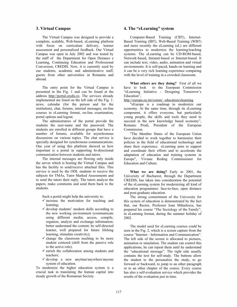
117
3. Virtual Campus
The Virtual Campus was designed to provide a complete, scalable, Web-based, eLearning platform with focus on curriculum delivery, learner assessment and personalized feedback. Our Virtual Campus was open in July 2002 and was tested by the staff of the Department for Open Distance e Learning, Continuing Education and Professional Conversion, CREDIS. Now, it is currently used by our students, academic and administrative staff, guests from other universities in Romania and abroad.
The entry point for the Virtual Campus is
presented in the Fig. 1 and can be found at the address http://portal.credis.ro. The services already implemented are listed on the left side of the Fig. 1: news, calendar (for the person and for the institution), chat, forums, internal messages, on-line courses in eLearning format, on-line examination, portal options and logout.
The administrators of the portal provide the students the user-name and the password. The students are enrolled in different groups that have a number of forums, available for asynchronous discussions on various topics. The chat service is specially designed for synchronous communications. One year of using this platform showed us how important is a portal in supporting bi-directional communication between students and tutors.
The internal messages are flowing only inside the server which is hosting the Virtual Campus and has the facility to send/receive attached files. This service is used by the ODL students to receive the subjects for TMAs, Tutor Marked Assessments and to send the tutors their reply. The tutors analyze the papers, make comments and send them back to the students.
Such a portal might help the university to:
increase the motivation for teaching and learning; develop students’ modern skills according to the new working environment (communicate using different media; access, compile, organize, analyze and exchange information; better understand the content; be self-directed learner, well prepared for future lifelong learning; stimulate creativity); change the classroom teaching to be more student centered (shift from the passive role to the active role); enrich the collaboration among students and teachers; develop a new anytime/anywhere/anyone system of education.
To modernize the higher education system is a crucial task in translating the human capital into steady growth of the Romanian Society.
4. The “eLearning” system
Computer-Based Training (CBT), Internet-Based Training (IBT), Web-Based Training (WBT) and more recently the eLearning (eL) are different opportunities to modernize the learning/teaching systems. The eLearning can be CD-ROM-based, Network-based, Intranet-based or Internet-based. It can include text, video, audio, animation and virtual environments. It is self-paced, hands-on learning and it can be a very rich learning experience comparing with the level of training in a crowded classroom.
What others are they doing? First of all we
have to look to the European Commission “eLearning Initiative - Designing Tomorrow’s Education”, http://europa.eu.int/comm/ education/elearning
"eEurope is a roadmap to modernize our economy. At the same time, through its eLearning component, it offers everyone, but particularly young people, the skills and tools they need to succeed in the new knowledge based economy”, Romano Prodi, President of the European Commission.
"The Member States of the European Union have decided to work together to harmonize their policies in the field of educational technology and share their experience. eLearning aims to support and coordinate their efforts and to accelerate the adaptation of education and training systems in Europe", Viviane Reding Commissioner for Education and Culture.
What we are doing? Early in 2001, the
University of Bucharest, through the Department CREDIS, has taken into consideration the potential of the eLearning system for modernizing all kind of education programmes: face-to-face, open distance and post-graduate education.
The strong commitment of the University for this system of education is demonstrated by the fact that, our Rector, Professor Ioan Mihailescu, has prepared his course “The Sociology of the Family”, in eLearning format, during the summer holiday of 2002.
The model used for eLearning courses could be
seen in the Fig. 2, which is a screen capture from the course “Internet - Information and Communication”. The left side of the screen is allocated to pictures, animation or simulation. The student can control this applications, he can repeat them until he understand the “educational message”. The right side usually contains the text for self-study. The buttons allow the student to the personalize the study, to go forward or backward, to jump to an other paragraph or to an other chapter of the course. Every course has also a self-evaluation service which provides the results of the evaluation just in time.

118
The staff of the Department CREDIS has designed and produced the first course modules in eLearning format for training courses targeted to the ECDL Certification. They were implemented on the portal in October 2002 and they were used by 100 administrative staff of the University, 140 students from the Faculty of Biology, 70 students from the Faculty of Pedagogy and Education Sciences etc. The access point for these courses is included in the portal, Fig.3.
Figure 3. Training courses for ECDL
Nowadays, the Department CREDIS has more
than 40 courses in eLearning format, most of them in the area of Information Technology. The keys to successful eLearning include:
1. Varying the types of content (images, animations, simulations, sounds, text) that will result in better retention of the material.
2. Creating interaction that engages the attention and creates more interest, which in turn builds better retention.
3. Providing immediate feedback. A good eLearning course has to produce an immediate feedback to the student in order to correct the misunderstanding. The more immediate the feedback the better, because each step of learning builds upon the previous step which has to be correct.
4. Encouraging interaction with other students and tutors through chat service, forums, instant messaging and e-mail.
5. Building an online community may significantly influences the online programs.
The eLearning has benefits over traditional classroom training like:
It's less expensive to produce. Synchronous programs will have costs associated with tutoring and management, but will still be lower than traditional courses.
It's self-paced. The eLearning courses have a modular structure that allow the student to go through smaller blocks of training that can be used and absorbed for a while before moving on.
It moves faster. The learners can skip the material they already know/understand and move onto the issues they need training on.
eLearning eliminates the problems associated with different instructors teaching slightly different material on the same subject.
It can work from any location and any time. The student can go through training sessions from anywhere, usually at anytime. This system can make learning possible for people who never would have been able to attend the academic courses.
It can be updated easily and quickly. It is cheaper to update the eLearning resources on the server than reprinting manuals.
It can lead to increased retention. There is also the ability to revisit or replay sections of the training that might not have been clear the first time around.
It can be easily managed for large groups of students, spread all over the country.
5. Public-Private Partnership
Some of the courses were obtained through the
public-private partnership that we have established with valuable international partners.
The Department CREDIS is Regional and Local Academy for the CNAP – CISCO Networking Academy Program (http://cisco.netacad.net).
The CNAP is a comprehensive e-learning program, which provides students with the Internet technology skills essential in a global economy. The Networking Academy program delivers Web-based content, online assessment, student performance tracking, hands-on-labs, instructor training and support, and preparation for industry standard certifications. There are more than 300,000 students enrolled in 140 countries, studying the same curriculum and passing the same examinations. The CISCO Certificates obtained in Romania are recognized all over the world.
The Department CREDIS is the first Romanian university included in the Microsoft IT Academy Program and have access to the MOC courses.
Those programs are very good examples of the potential of the eLearning systems for globalization.

119
From MBone to M6Bone
Assistant Lecturer Madalina Mlak Academy of Economic Studies – Bucharest, Faculty of Economic Cybernetics, Statistics, and
Abstract This paper present a parallel between networks MBone and M6Bone, the connection between those networks and hosts, the map of sites connected to M6Bone network. Keywords: MBone, M6Bone, IPv6, multicast, routing protocols. 1. Parallel MBone-M6Bone 1.1. MBone origin In 1992 was born MBone (Multicast Backbone). The MBone created from experiments during IETF (Internet Engineering Task Force) meeting in which live audio and video were transmitting around the world. 1.2. What is the MBone? The MBone network is a group of sites (a network of hosts) connected to the Internet which communicating using a technique called IP multicast and using to develop protocols and applications. MBone allows multicast packets to travel through routers that are set up to handle only unicast traffic. In order to participate in the MBone network it is necessary to have a workstation supporting IP multicast and to have a network connection with a reasonable bandwidth (typically around 1 Mbps). The necessary of IP multicast and software applications in freely is available. 1.3. How large is the MBone? The size of MBone compared to the Internet as a whole is relatively small (~ a few percent of the Internet).
1.4. MBone topology Within a continent, the MBone topology will be a combination of mesh and star: the backbone and regional network will be link by mesh of tunnels. Some redundant tunnels may be configuring with higher metrics for robustness. Then each regional network will have a star hierarchy hanging off are node of the mesh to fan out and connect too all the customer networks that want to participate. Between continents, there will probably be only one or two tunnels, preferably terminating at the closet point on the MBone mesh. 1.5. M6Bone origin This project which started in July 2001 and the scope is to offer an IPv6 multicast service for sites. This service is based on Renater3 (IPv6 enable network), on G6 group (French group of IPv6 testers) and benefits from the logistic support of the Aristote Association which is involved in the broadcasting of the modern technologies. 1.6. What is the M6Bone? M6Bone is an experimental IPv6 Multicast network. M6Bone allow people who are connect to learn about IPv6 multicast and M6Bone is a good place to test IPv6 multicast equipments, configurations, implementations or software and to develop new protocols and services. 1.7. M6Bone topology The M6Bone have to use a different topology for IPv6 multicast and IPv6 unicast traffic. If the IPv6 multicast and unicast topologies are not the same, the IPv6 multicast routing protocol performs the RPF check using the multicast routing table. In actual IPv6 native networks, multicast routing is not available on the routers. That is why this project

120
decided to develop the M6Bone with tunnel architecture with edge equipments supporting IPv6 multicast. Today, Renater provides a central router that is pleased to welcome sites willing to connect. The way to connect to the M6Bone is to create a tunnel between an existing M6Bone router (for example, Renater) and a site.
• for sites that already have an IPv6 connectivity, the tunnel will be an IPv6 (multicast) in IPv6 (unicast) tunnel;
• for sites that only have an IPv4 connectivity, the tunnel will be an IPv6 (multicast) in IPv4 tunnel.
IPv6 in IPv6 and IPv6 in IPv4 tunnels are deploy to connect M6Bone routers. 1.8. How large is the M6Bone? Today over 35 sites in Europe and beyond are connect to the M6Bone, as shown in word map. 1.9. The world and European map The world and European map of the M6Bone are present in the following pictures:

121
1.10. Sites connected to the M6Bone Examples of sites connected to the M6Bone. List of the connected sites is much more but in the following are present some of them: France: GIP Renater, Paris Aristote, Paris DESS ART, Paris IRISA/INRIA, Rennes Université de Bretagne sud, Vannes Université Louis Pasteur, Strasbourg Belgium: Université Libre de Bruxelles Luxembourg: RESTENA Nederland: Surfnet Finland: Oulu University Oulu Polytehnic Norway: Osfold College Germany: JOIN Poland: Poznan Supercomputing and Networking Austria: Vienna University Computer Center Spain: UPM, Madrid University of Murcia Italy: CNR-IIT UK: University College of London Dante, Cambridge University of Southampton SUA: Wichita State University, Wichita, Kansas Philippines:ASTO , Quezon Taiwan: ASCC Senegal: ESMT, Dakar Korea: ETRI Mexico: UdeG, Guadalajara Collaboration for M6Bone Connect to the M6Bone and join the mailing list: [email protected]. Send an e-mail to [email protected] with message "subscribe m6bone". 2. IP multicast 2.1. IP multicast addresses Every IP multicast group has a group address IP multicast provides only open groups. That is it is not necessary to be a member of a group in order to send datagrams to the group. Multicast address is like IP addresses used for single hosts and it is writing in the same way. Multicast addresses will never have conflict with host addresses because a part of the IP address space is specifically reserve for multicast. The multicast addresses are in the range from 224.0.0.0 to 239.255.255.255. However, the multicast addresses from 224.0.0.0 to 224.0.0.255 are reserve for multicast routing information. Applications
programs should use multicast addresses outside this range. Multicast address assignment is generally dynamic and under the control of collections of the users. 2.2. Class D address A multicast IP packet has a class D address used for multicast (from 224.0.0.0 to 239.255.255.255). Class D (Table 1.) has a first bit value of one and second bit value of 1, third bit value of 1 and fourth bit value of 0. The other 28 bits are using to identify the group of computers the multicast message is intending for these. Class D accounts for 1/16th (268,435,456 or 228) of the available IP addresses.
31 23 15 7 0 Net Host or Node 224. 24.53.107
Tabel 1. Class D address There is no restriction on the physical location or number of members in a multicast group and it possible that they may be members of more that one multicast group. IP multicast packets are encapsulating for sending through tunnels, so that they look like normal unicast datagrams to intervening routers and subnets. A multicast router, which wants to transmit a multicast packet across a tunnel, will prep ending another IP header. A multicast router set the destination address in the new header to be a unicast address of the multicast router at the other end of the tunnel and set the IP protocol field in the new header to be four, which means the next protocol is IP. 2.3. IPv6 addressing architecture IPv6 addresses are 128-bit identifiers for interfaces and sets of interfaces. There are three types of addresses:
• unicast: an identifier for a single interface. A packet sent to a unicast address is delivered to the interface identified by that address;
• anycast, multicast: identifiers for a set of interfaces (typically belonging to different nodes);
• broadcast: is replaced by multicast. Multicasting is a technical term, a network routing facility that means a method of sending packets to multiple sites at the same time. How big a packet is depends on the protocol involved. Multicasting is the ability of the network to efficiently delivering information to multiple recipients.

122
2.4. Unicast-prefix based IPv6 multicast address An extension to the multicast addressing architecture that allows for unicast-prefix-based allocation of multicast addresses. By using those types of addresses, network operators will be able to identify their multicast addresses without need to run an inter-domain allocation protocol. • flags is a set of 0|0|P|T: if P=0 indicates a
multicast address that is not assigned based on the network prefix. This indicates a multicast address as defined in RFC2273; if P=1 indicates a multicast address that is assigned based on the network prefix; if P=1, T must be set to 1, otherwise the setting of the T bit is defined in section 2.7 of RFC2273
• the reserved field must be zero. • plen indicates the actual number of bits in the
network prefix field that identify the subnet when P=1
• network prefix identifies the network prefix of the unicast subnet owning the multicast address. If IP=1, this field contains the unicast network prefix assigned to the domain owning, or allocating, the multicast address. All non-significant bits of the network prefix field should be zero
• group ID is set based on the guidelins outlined in RFC3307.
2.5. Ipv6 multicast address Structure of IPv6 multicast address is presents in the following table:
8 4 4 112 bits 11111111 flags scope group ID
Table 2. Structure of IPv6 multicast address
• 11111111=FF: at the start of the address identifies the address as being a multicast address
• flags (0|0|0|T): if T=0,indicates a permanently-assigned (“well-known”), and must be initialized to 0; if T=1,indicates a non-permanently assigned (“transient”) multicast address
• scope of the multicast group and the value are: 0,F reserved, 1 node-local scope, 2 link-local scope, 3,4,6,7,9,A,D unassigned, 5 site-local scope, 8 organization-local scope, E global scope.
• group IP identifies the multicast group, either permanent or transient, within the given scope.
IANA (Internet Assigned Numbers Authority) handles both fixed and variable scope for multicast address allocations. 2.6. IPv6 anycast address Structure of IPv6 anycast address is presents in the following table:
Table 3. Structure of IPv6 anycast address • an IPv6 anycast address is an address that is
assigned to more than one interface (typically belonging to different nodes);
• a packet sent to an anycast address is routed to the “nearest” interface having that address, according to the routing protocols measure of distance;
• anycast addresses are allocated from the unicast address space, using any of the defined unicast address formats;
• for any assigned anycast address there is a longest address prefix P that identifies the topological region in which all interfaces belonging to that anycast address reside.
3. IPv6 multicast hosts An IPv6 multicast host has: • to have an IPv6 stack that supports MLD
(Multicast Listener Discovery); • to be to run mbone tools.
Many tools are already available and can be install on almost all operating systems having IPv6 stack. Examples of available operating systems, which support IPv6: • FreeBSD • Linux or Red Hat Linux • Windows2000 or Windows XP
For example to install mbone tools on Windows XP. The operating systems configuration follows those steps:
1. first install the Service Pack1 2. second install the IPv6 stack 3. after that open a DOS command prompt and execute the command: ipv6 install
To install mbone tools on Windows XP download the software on http://www.kabassanov.com (Microsoft part). To run mbone tools on Windows XP your computer must be in the IPv6 DNS of your site.
8 4 4 8 8 64 32 11111111 flags scope reserved plen network
prefix group
ID

123
For Windows 2000 download and install the IPv6 stack from http://msdn.microsoft.com/downloads/ sdks/platform/tpipv6.asp. To run mbone tools on Windows 2000 your computer must be in the IPv6 DNS of your site. 4. IPv6 routing and tunnels The PIM (Protocol Independent Multicast) protocol uses unicast routing table for RPF (reverse-path-forwarding) check. It implies that unicast and multicast topologies must be the same. It is not the case since the M6Bone is an overlay network. A solution to this problem is to use a multicast routing table but it is not yet implement on IPv6 multicast routing equipment. The sites have to use separate routers for unicast and multicast. The IPv6 multicast tunnels are setup between IPv6 multicast routers. Those routers exchange their unicast routing table that will be use for RPF check using RIPng (Routing Information Protocol next generation) protocol. With RIPng, each site will advertise its prefix corresponding to the subnet where IPv6 multicast is enabling through the tunnel, but a problem occurs when you set up an IPv6 in IPv6 tunnel: in order to set up the tunnel, you need to reach the destination of the tunnel via the unicast network. You must to be sure that the address of the tunnel end point is not included in a prefix advertised on the M6Bone if this is the case (topology choice) you need to specify a static route to the tunnel end point through the unicast network. Note that it is not possible with this solution to run multicast applications on the multicast routers. 4.1. IPv6 multicast routing protocols In the real world, there are many different multicast routing protocols, each with its own advantages and disadvantages. Examples of protocols: Flood and Prune Protocols (DVMRP and DM-PIM), MOSPF, Center-Based Tree (CBT, SM-PIM and BGMP). DVMRP (Distance Vector Multicast Routing Protocol) computes its own routing table to determine the best path back to the source. DM-PIM (Dense-Mode Protocol Independent Multicast) uses RPF and looks a lot like DVMRP. The most significant difference between DVMRP and
DM-PIM is that PIM does not require any particular unicast protocol. For DVMRP and DM-PIM their flood-and-prune nature requires off-tree routers to keep per-source state. MOSPF is the multicast extension to OSPF (Open Shortest Path First) which is a unicast link-state routing protocol. CBT (Core-Based Trees) was the earliest center-based tree protocol and is the simplest. The important advance that SM-PIM (Sparse-Mode Protocol Independent Multicast) made over CBT was to realize that discovering who senders are could be separate from building efficient trees from those senders to receivers. The equivalent of CBT core is calling a Rendezvous Point (RP) in PIM. The BGMP (Border Gateway Multicast Protocol) protocol is an attempt to design a true inter-domain multicast routing protocol, one that can scale to operate in the global Internet. 5. IPv6 multicast connectivity 5.1. IPv6 multicast routers However, when an IPv6 multicast routers receives a packet, it performs an RPF check. The RPF check is performing using the IPv6 unicast routing table. For this reason, it was necessary to have the same topology for IPv6 multicast and IPv6 unicast. Each router's table is unique and contains information of how and where to transmit packets to other routers. The IPv6 multicast router has to be able to manage: • IPv6 in IPv6 tunnels if you have an IPv6
connectivity; • IPv6 in IPv4 tunnels if you have an IPv4
connectivity; • SM PIM for the construction of the shared tree; • RIPng for the unicast routing (it must be possible
to activate RIPng in the tunnels) 5.2. IPv6 multicast-IPv4 multicast gateway This gateway, developed by Luc Beurton from the University of South Britany, permit to have at the same and on the same session sites sending in multicast IPv4 and sites sending in multicast IPv6. In the transition between IPv6 and IPv4 it could be possible to have only one IPv6 transmission to transmit in the same time on the M6Bone (IPv6) and in the MBone (IPv4).
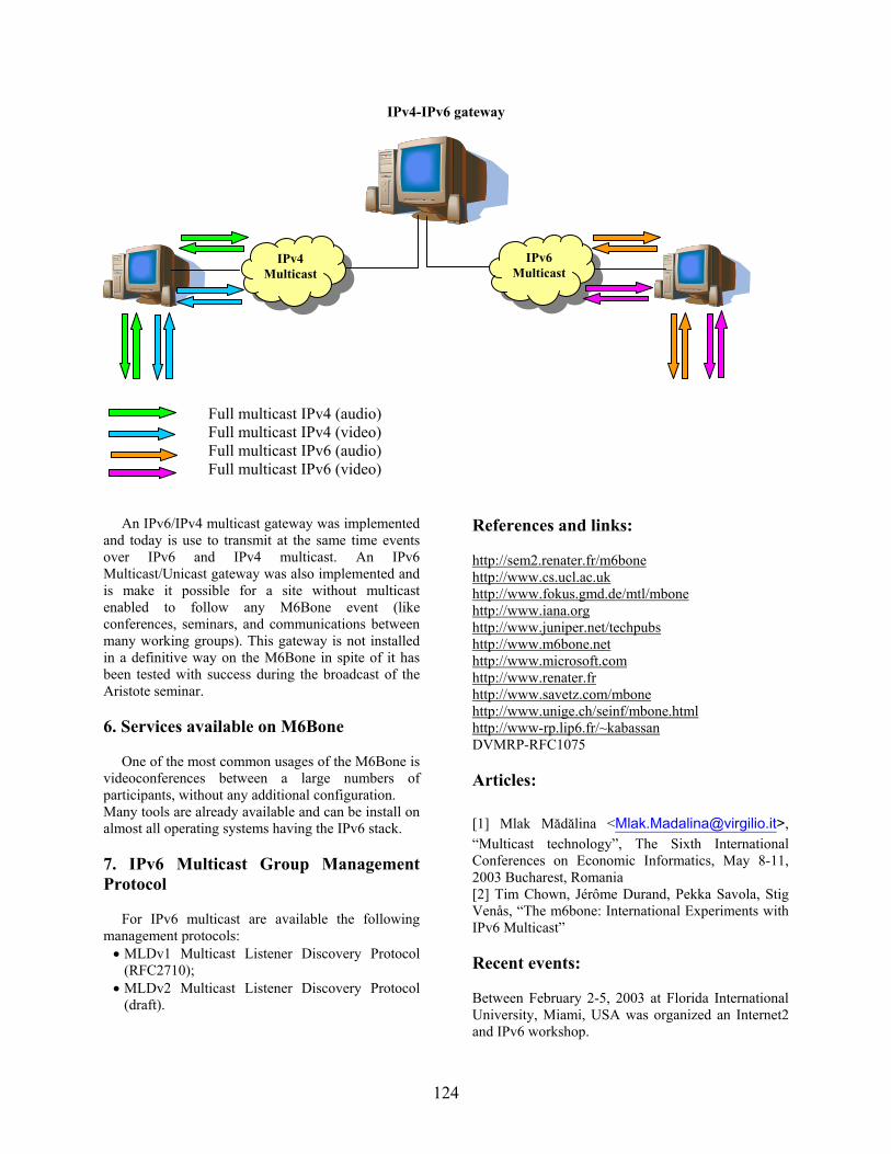
124
IPv4-IPv6 gateway
Full multicast IPv4 (audio) Full multicast IPv4 (video) Full multicast IPv6 (audio) Full multicast IPv6 (video) An IPv6/IPv4 multicast gateway was implemented and today is use to transmit at the same time events over IPv6 and IPv4 multicast. An IPv6 Multicast/Unicast gateway was also implemented and is make it possible for a site without multicast enabled to follow any M6Bone event (like conferences, seminars, and communications between many working groups). This gateway is not installed in a definitive way on the M6Bone in spite of it has been tested with success during the broadcast of the Aristote seminar. 6. Services available on M6Bone One of the most common usages of the M6Bone is videoconferences between a large numbers of participants, without any additional configuration. Many tools are already available and can be install on almost all operating systems having the IPv6 stack. 7. IPv6 Multicast Group Management Protocol For IPv6 multicast are available the following management protocols: • MLDv1 Multicast Listener Discovery Protocol
(RFC2710); • MLDv2 Multicast Listener Discovery Protocol
(draft).
References and links: http://sem2.renater.fr/m6bone http://www.cs.ucl.ac.uk http://www.fokus.gmd.de/mtl/mbone http://www.iana.org http://www.juniper.net/techpubs http://www.m6bone.net http://www.microsoft.com http://www.renater.fr http://www.savetz.com/mbone http://www.unige.ch/seinf/mbone.html http://www-rp.lip6.fr/~kabassan DVMRP-RFC1075 Articles: [1] Mlak Mădălina <[email protected]>, “Multicast technology”, The Sixth International Conferences on Economic Informatics, May 8-11, 2003 Bucharest, Romania [2] Tim Chown, Jérôme Durand, Pekka Savola, Stig Venås, “The m6bone: International Experiments with IPv6 Multicast” Recent events: Between February 2-5, 2003 at Florida International University, Miami, USA was organized an Internet2 and IPv6 workshop.
IPv4 Multicast
IPv6 Multicast

125
Practical Analysis of TCP Implementations: Tahoe, Reno, NewReno
Bogdan Moraru Technical University
of Cluj-Napoca Bogdan.Moraru@
com.utcluj.ro
Flavius Copaciu Technical University
of Cluj-Napoca Flavius.Copaciu@
com.utcluj.ro
Gabriel Lazar Technical University
of Cluj-Napoca Gabriel.Lazar@
com.utcluj.ro
Virgil Dobrota Technical University
of Cluj-Napoca Virgil.Dobrota@
com.utcluj.ro
Abstract
The paper presents the experimental evaluation of the existing TCP implementations: Tahoe without Fast Retransmit, Reno, New-Reno. The short time analysis involved a software tool called TBIT (TCP Behavior Inference Tool), which was designed by AT&T Center for Internet Research. It generates short TCP traffic (about 25 segments), with the 13th and the 16th segments intentionally dropped. Depending on the type of TCP implementation the behavior was different, due to the activation/missing of the following congestion control algorithms: "Slow-Start", "Congestion Avoidance", "Fast Recovery" and "Fast Retransmit". TCP segments were captured at both ends of the TCP connection using tcpdump tool and then the data was analyzed with several programs (tcptrace, xplot and proprietary programs developed for Linux Red Hat). 1. Introduction
During the last years, computer networks have experienced tremendous growth. More and more computers get connected to both private and public networks, the most common protocol stack used being TCP/IP.
Nowadays it is difficult to identify the congestion control algorithms that are currently implemented by various machines in Internet. The TCP header does not provide any information about them.
Another important issue is the way that these algorithms are implemented in different operating systems. By this time, the most frequent TCP implementation for clients is based on the Windows 2000 kernel. On the other hand, most Internet servers use various FreeBSD or Linux-based versions.
The related work on TCP congestion control covers at least two major issues. The first one
includes simulations based on theoretical analysis of TCP implementations, such as in [1]. Although new ideas could be tested, this kind of work is not always close to real implementations from the operating system’s kernel. For this reason, a second major issue is focused on real TCP implementations, such as in [2].
TCP is trying to provide reliable data transmission between two entities. It implies anyway to handle packet losses, that are due to transmission errors or traffic congestion.
2. TCP congestion control
Let us define the following parameters:
• sender maximum segment size (smss) represents the maximum amount of data that can be sent in a single TCP segment, without including the header.
• sender’s window (swnd) represents the maximum number of bytes that the can be sent. Its value is the lowest between receiver’s window and congestion window.
• receiver’s window (rwnd) is the latest window advertised by the receiver.
• congestion window (cwnd) is a TCP state variable, limiting the amount of data that can be sent.
• loss window (lw) is the value of the congestion window after a packet loss has been detected.
• slow-start threshold (ssthresh) is another TCP state variable that determines the congestion control algorithm to be employed: either slow-start (if cwnd ≤ ssthresh) , either congestion avoidance (if cwnd ≥ ssthresh).
Basic TCP congestion control is done using
Slow-Start and Congestion Avoidance algorithms, based on the work initiated by Van Jacobson.

126
According to [3] these algorithms are mandatory, but they could be accompanied by two new ones: Fast Retransmit and Fast Recovery.
2.1 Slow-Start and Congestion Avoidance
These two algorithms must be implemented by
TCP entities in order to control the amount of data sent over the network.
The Slow-Start, improperly called like this, actually increases exponentially the size of the congestion window. It is used by a TCP entity at the beginning of a transmission or after detecting a packet loss. The purpose of Slow-Start is to fill as soon as possible a transmission channel.
Figure 1. Slow-Start and Congestion Avoidance
After the congestion window has reached the
threshold value, the Congestion Avoidance algorithm is employed. It continues to increase linearly the congestion window, adding up to one SMSS but not less then one byte. In both cases a retransmission timer is used for every packet. The timeout signals the loss of the packet. This leads to the retransmission of that packet and halving of the Slow-Start threshold. The congestion window is also set to the value of the loss window. 2.2 Fast Recovery and Fast Retransmit
After implementing the previous two algorithms, new problems arise. The first one is related to the packet loss detection. Normally a packet loss is inferred based on the timeout of the retransmission timer. This, however, may lead to significant delays in data transmissions, so another way to determine packet loss has been added to TCP.
Under normal circumstances a TCP entity must send a duplicate ACK for every packet that arrives out of sequence. A packet may be received out of sequence due to packet duplication by the network, packet delays or loss.
The Fast Retransmission algorithm considers that a packet has been lost when it receives 3 duplicate ACKs, before the timeout of the retransmission timer. In this way valuable time is saved.
The second problem is related to the drastic decrease of the congestion window after a packet loss detection. If a packet is lost during Slow-Start or Congestion Avoidance the value of the congestion window is set to the value of the loss window (1 SMSS). The Fast Recovery algorithm tackles this problem. The new value of the congestion window after a packet loss is detected by the Fast Retransmission is set to ssthresh + 3 SMSS. This is called “artificial inflation” of the congestion window. Beside that, for every new duplicate ACK received the congestion window is further increased with 1 SMSS.
3. Tools and Environment
3.1 Tools
In order to identify the TCP implementation
within the operating system’s kernel, an apache web server should run on the tested host. This software is free and there are ports available for all the systems we tested.
The TCP packets exchanged between the testing and the tested system were captured using tcpdump and stored for analysis. On Windows systems ethereal was preferred. The most important tool we used was TBIT (TCP Behavior Inference Tool).
This tool was developed at AT&T Center for Internet Research and it can be used to characterize the behavior of a TCP implementation from a distant machine running a web server.
Generally speaking TBIT works like a regular web browser: it establishes a TCP connection to the web server and requires a web page. TBIT builds it’s own TCP packets and uses an IP socket to send them to the server. It also uses a Berkley Packet Filter to prevent the TCP packages received from the web server from reaching the operating systems kernel and to redirect them towards TBIT. Then TBIT creates controlled packet loss by confirming only certain received packets. The web server interprets those losses as a sign of congestion and reacts according to the congestion control algorithms it implements. This reaction can be analyzed, the algorithms used can be recognized and the TCP version estimated.
3.2 Network Configuration
In order to perform the experiments we used 2
machines: the testing system and the tested system. The testing machine was based on FreeBSD 4.5 with a recompiled kernel (according to TBIT specifications), TBIT and tcpdump. On the tested system we installed various versions of FreeBSD, Linux and Windows. A web server plus tcpdump or ethereal ran on the system. The testbed configuration is presented in Figure 2.
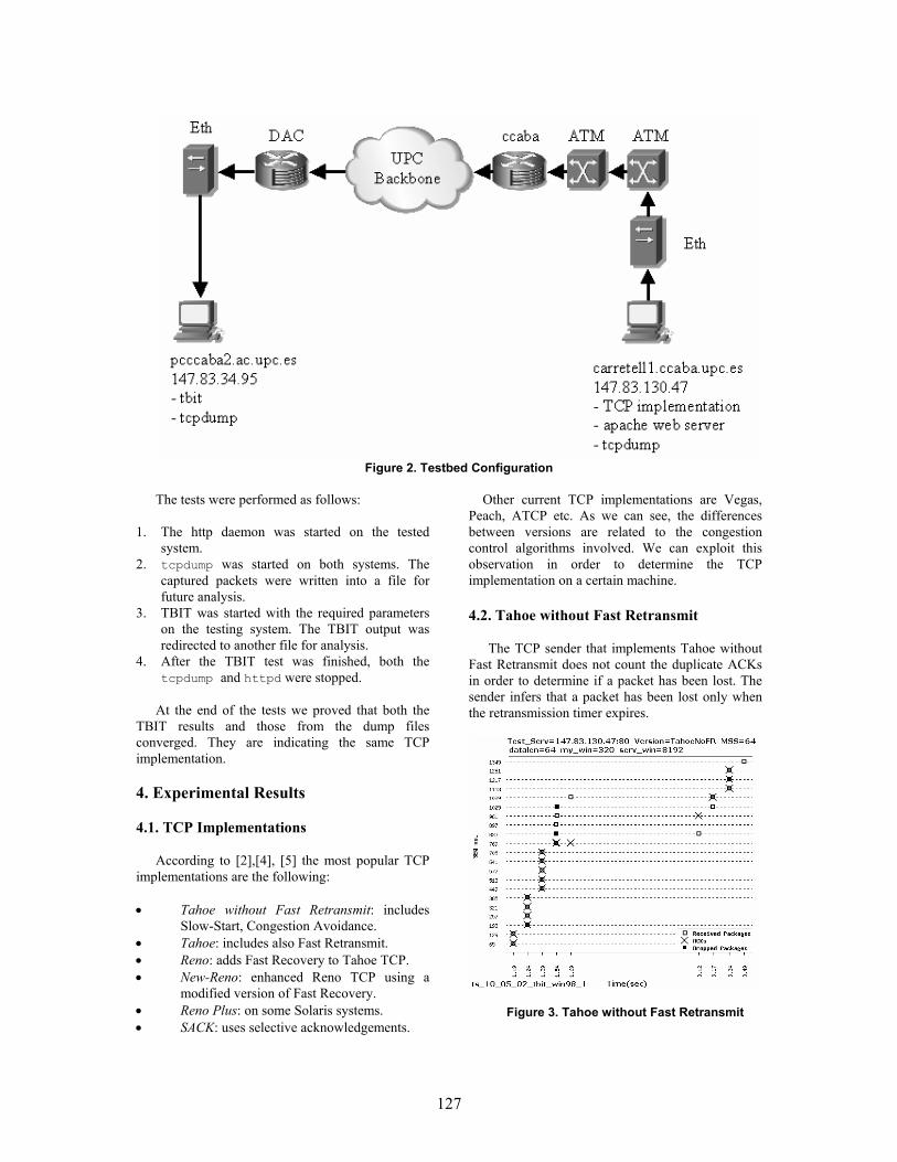
127
Figure 2. Testbed Configuration
The tests were performed as follows:
1. The http daemon was started on the tested system.
2. tcpdump was started on both systems. The captured packets were written into a file for future analysis.
3. TBIT was started with the required parameters on the testing system. The TBIT output was redirected to another file for analysis.
4. After the TBIT test was finished, both the tcpdump and httpd were stopped.
At the end of the tests we proved that both the
TBIT results and those from the dump files converged. They are indicating the same TCP implementation.
4. Experimental Results
4.1. TCP Implementations
According to [2],[4], [5] the most popular TCP implementations are the following:
• Tahoe without Fast Retransmit: includes
Slow-Start, Congestion Avoidance. • Tahoe: includes also Fast Retransmit. • Reno: adds Fast Recovery to Tahoe TCP. • New-Reno: enhanced Reno TCP using a
modified version of Fast Recovery. • Reno Plus: on some Solaris systems. • SACK: uses selective acknowledgements.
Other current TCP implementations are Vegas, Peach, ATCP etc. As we can see, the differences between versions are related to the congestion control algorithms involved. We can exploit this observation in order to determine the TCP implementation on a certain machine. 4.2. Tahoe without Fast Retransmit
The TCP sender that implements Tahoe without
Fast Retransmit does not count the duplicate ACKs in order to determine if a packet has been lost. The sender infers that a packet has been lost only when the retransmission timer expires.
Figure 3. Tahoe without Fast Retransmit

128
This implementation includes two algorithms only: Slow Start and Congestion Avoidance. Figure 3 describes the working mode of this implementation: 1. The first 12 packets are acknowledged
appropriately. 2. Packet 13 is dropped. 3. Packets 14 and 15 are acknowledged, but the
ACKs sent are duplicate ACKs for segment 12 4. Packet 16 is dropped 5. Packet 17 is acknowledged, but the ACK sent is
a duplicate ACK for segment 12 6. The last 5 segments were not acknowledged
properly so the sender cannot send anymore packets.
7. The transmission restarts (with Slow Start algorithm) when the retransmission timer for packet 13 expires (timeout). Segment 13 is retransmitted.
8. The ACK generated because of the correct reception of packet 13 is the ACK for packet 15, because packets 14 and 15 are already in the receiver’s buffer. This ACK segment acknowledges segments 13, 14 and 15.
9. Packet 16 is retransmitted, but there is also an useless retransmission of packet 17 because this packet is already in the receiver’s buffer
TCP TahoeNoFR is characterized by a
retransmission timeout for segment 13 and an useless retransmission of segment 17.
The situation when multiple packets are lost from one window is almost similar with the situation when there is only one packet lost from that window. The first lost packet will generate a retransmission timeout (a lot of time wasted), and all the lost packets will be retransmitted immediately afterwards.
This implementation performance is very poor especially when at least one packet per window is lost and packet loss happens very often. This would lead to many timeouts. 4.3. Tahoe TCP
Tahoe implementation added a number of new
algorithms and refinements to earlier implementations (including TCP without Fast Retransmit). The algorithms suite included Slow-Start, Congestion Avoidance and Fast Retransmit. With the latter one, after receiving a 3 duplicate acknowledgments for the same TCP segment, the data sender inferred that a packet has been lost and retransmitted the packet. Note that this happened before the retransmission timer generated timeout, leading to a higher channel utilization and connection throughput. Unfortunately, in practice
we were not able to find any workstations in the Internet currently using this TCP version. 4.4. Reno TCP
Figure 4. Reno TCP
Reno implements two new algorithms beside the
those ones implemented by TahoeNoFR: Fast Retransmit and Fast Recovery.
In Figure 4 the area for the first 18 segments is zoomed because the initial figure might create the idea that there is no Slow Start, which is not true. The implementation works as follows: 1. The first 12 packets are acknowledged
appropriately . 2. Packets 13 and 16 are dropped. 3. Segments 14, 15 and 17 generate duplicate
ACKs for segment 12. Because of the 3 consecutive duplicate ACKs, Fast Retransmit and Fast Recovery algorithms are started.
4. Packet 13 is fast retransmitted. 5. The received ACK confirms packets 13, 14, and
15, and asks for segment 16. This is a new and distinct ACK and because of it Fast Retransmit algorithm ends and a new packet is transmitted: 18.
6. Packet 18 generates a duplicate ACK for packet 15.
7. Since there are no new and distinct ACKs, no more data can be sent. Because there aren’t enough duplicate ACKs to start the Fast Retransmit algorithm for packet 16, transmission restarts only when the retransmission timer for packet 16 generates timeout.
8. When the timer expires, packet 16 is retransmitted, and because packets 17 and 18 are already in the receiver’s buffer, an ACK for packet 18 will be generated.
Fast Retransmission algorithm solves one
problem from TahoeNoFR: there is no timeout for the first packet lost for one window. But this

129
happens when we have a multiple packet loss from the same window. Reno TCP works best for only one lost packet per window. Another problem of TahoeNoFR that is solved by Reno is the useless retransmission of packet 17.
This was a problem because we were loading the network with unnecessary packets since they are already in the receiver’s buffer.
Reno TCP is characterized by a Fast Retransmit for packet 13, a Retransmit Timeout for packet 16, and no unnecessary retransmission of packet 17 (for the scenario described in Figure 5).
4.5. NewReno TCP
NewReno TCP is a variant of Reno with a little
modification within Fast Recovery algorithm. This was done in order to solve the timeout problem when multiple packets are lost form the same window.
Figure 5. NewReno TCP Figure 5 shows the way this implementation
works: 1. The first 12 packets are acknowledged
appropriately 2. Packets 13 and 16 are dropped 3. Segments 14, 15 and 17 generate duplicate
ACKs duplicate for segment 12. Because of the 3 duplicate ACK Fast Retransmit and Fast Recovery algorithms are started.
4. Packet 13 is fast retransmitted 5. The received ACK confirms packets 13, 14, and
15, and it asks for segment 16. This is a new and distinct ACK, but an intermediate one (it acknowledges only some of the segments not all the segments that need to be acknowledged). Because of it Fast Retransmit algorithm does not stop, and is applied for segment 16
6. Segment 16 is fast retransmitted and it generates an ACK for segment 17, because packet 17 already in the receiver’s buffer.
7. All the packets that needed to be acknowledged were acknowledged, so the Fast Retransmit algorithm stops.
Note that higher performances were obtained
due to the little modification of Reno TCP. Although NewReno solves the timeout problem when multiple packets are lost form the same window, it can retransmit only one packet per Round Trip Time.
4.6. RenoPlus TCP
This implementation was found on Solaris 2.51. In Figure 6 it can be observed the way this
implementation works, and also that this implementation does not perform a correct Slow Start.
Figure 6. RenoPlus TCP 1. The first 12 packets are acknowledged
appropriately. 2. Packets 13 and 16 are dropped. 3. Segments 14, 15 and 17 generate duplicate
ACKs duplicate for segment 12. Because of the 3 duplicate ACK Fast Retransmit and Fast Recovery algorithms are started.
4. Packet 13 is fast retransmitted. 5. The received ACK confirms packets 13, 14, and
15, and it asks for segment 16. This new and distinct ACK is not considered as an intermediate ACK (like NewReno). Because of this ACK segments 18, 19 and 20 are transmitted.
6. These 3 segments will generate duplicate ACKs for segment 15. Fast Retransmit and Fast Recovery algorithms are started.
7. Packet 16 is fast retransmitted.
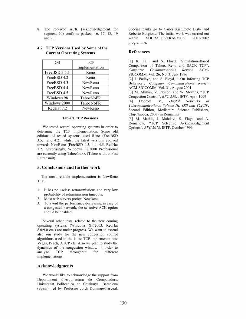
130
8. The received ACK (acknowledgement for segment 20) confirms packets 16, 17, 18, 19 and 20.
4.7. TCP Versions Used by Some of the Current Operating Systems
OS TCP Implementation
FreeBSD 3.5.1 Reno FreeBSD 4.2 Reno FreeBSD 4.3 NewReno FreeBSD 4.4 NewReno FreeBSD 4.5 NewReno Windows 98 TahoeNoFR
Windows 2000 TahoeNoFR RedHat 7.2 NewReno
Table 1. TCP Versions
We tested several operating systems in order to
determine the TCP implementation. Some old editions of tested systems used Reno (FreeBSD 3.5.1 and 4.2), whilst the latest versions evolved towards NewReno (FreeBSD 4.3, 4.4, 4.5, RedHat 7.2). Surprisingly, Windows 98/2000 Professional are currently using TahoeNoFR (Tahoe without Fast Retransmit). 5. Conclusions and further work The most reliable implementation is NewReno TCP. 1. It has no useless retransmissions and very low
probability of retransmission timeouts. 2. Most web servers prefers NewReno. 3. To avoid the performance decreasing in case of
a congested network, the selective ACK option should be enabled.
Several other tests, related to the new coming
operating systems (Windows XP/2003, RedHat 8.0/9.0 etc.) are under progress. We want to extend also our study for the new congestion control algorithms used in the latest TCP implementations: Vegas, Peach, ATCP etc. Also we plan to study the dynamics of the congestion window in order to analyze TCP throughput for different implementations. Acknowledgments
We would like to acknowledge the support from
Departament d’Arquitectura de Computadors, Universitat Politecnica de Catalunya, Barcelona (Spain), led by Professor Jordi Domingo-Pascual.
Special thanks go to Carles Kishimoto Bisbe and Roberto Borgione. The initial work was carried out within SOCRATES/ERASMUS 2001-2002 programme.
References [1] K. Fall, and S. Floyd, “Simulation–Based Comparison of Tahoe, Reno and SACK TCP”, Computer Communications Review ACM-SIGCOMM, Vol. 26, No. 3, July 1996 [2] J. Padhye, and S. Floyd, “ On Inferring TCP Behavior”, Computer Communications Review ACM-SIGCOMM, Vol. 31, August 2001 [3] M. Allman, V. Paxson, and W. Stevens, “TCP Congestion Control”, RFC 2581, IETF, April 1999 [4] Dobrota, V., Digital Networks in Telecommunications. Volume III: OSI and TCP/IP, Second Edition, Mediamira Science Publishers, Cluj-Napoca, 2003 (in Romanian) [5] M. Mathis, J. Mahdavi, S. Floyd, and A. Romanow, “TCP Selective Acknowledgement Options”, RFC 2018, IETF, October 1996

131
Pilot Cooperative System in Sustaining Project Management Activities
Cristina NICULESCU* Radu ION**
Research Institute for Artificial Intelligence, Calea 13 Septembrie 13, Bucharest 74311, ROMANIA
Tel.: +(40 21) 410-2953, Fax: +(40 21) 411-3916 *E-mail: [email protected] **E-mail: [email protected]
Abstract
The convergence of the tendencies evolving on the technology and education realm is representing by the fusion of the activities implied in knowledge management, learning and performance. The subject of our work is to design a system that allows groups to collaborate over computer networks. Our implemented pilot system is an e-learning collaborative tool for assisting stakeholders in project management activities. Diverse usage scenarios of the system are also depicted. The functional software modules are: virtual meeting forum, classifier and organizer texts module, social proxy module, retrieving information service module, user profile module and sharing files module. The social proxy module has the role of mutual awareness and responsibility. Software modules integration in the collaborative learning system is facilitated by the XML technology. Designing our pilot cooperative e-learning system takes into account the flexibility and scalability features of the knowledge management system architecture, allowing integrating new elements later. KM is seen as a cyclic process of the three correlated activities: creating, integrating and dissemination of knowledge.
1. Introduction
The conditions under which knowledge based work is done are clearly different from those of the traditional industrial and/or service work and therefore the established criteria of work design cannot be simply copied. New approaches, concepts and methods are necessary to create optimum conditions for productive, healthy and attractive knowledge work at the organizational, team and individual level.
In the actual knowledge-based society, the activities in domains of all kind (productive, of design, economic, research, and of other nature) are interconnected with training activity. Therefore, the
necessity of continuous education at working places arose. That is why one has to find efficient training methods, to solve problems, as the persons have to be able:
to learn without leaving work places; to learn about subjects related to their
instant work; to learn cooperatively with other persons,
interested in the same domains, but located in other places;
to share information resources with their co-learners.
Computer Supported Collaborative Learning (CSCL) environments answer to these requests.
At the present time we are facing a paradigmatic change in developing learning assisted systems: in the last years their development was technology centered, but nowadays their development centers on the application of specific human behavior concepts in using the new learning, communications and business technologies.
2. Social infrastructure for cooperative e-learning
In the physical world, unlike the virtual one, people are remarkably skilled to use subtle cues about the presence and activities of others to govern their interactions. One example should be mere presence of a person or facial expressions of other persons. We are also aware that our own activities provide information to others.
The informatics system has to make perceptible the social cues of the stakeholders in a virtual learning group. Actually, we are not speaking about a “total social transparence”, but a “social translucence” [2]. In fact, even in the physical environments a total social transparence is not possible: sometimes, only our awareness about the interaction of other persons of the group, without knowledge of what they have discussed, may change our attitude.
The system has to support mutual awareness and accountability to the group members. Therefore, it is easier to discuss coherently, to watch and imitate other persons’ actions, to conform to social

132
conventions and to engage in other collective interactions forms.
Figure 1. Social Proxy - visualization of the collective interactions
Without using the technological possibilities of
the videoconference systems, we can design a “social proxy”, as the social infrastructure in a collaborative e-learning application. This is a minimalist visualization of people and their activities [2], a graphical representation in every participant’s software interface (Fig.1.).
Each participant is marked in the graphical representation by a small colored circle that is approaching the middle of the ring, as soon as the person joins the discussion forum. On one hand, this social proxy is to be used on-line, in the virtual discussion forum; on the other hand, it can store statistical evidences on the participations in the conversation of the group members. The talks are also stored and they can be characterized by subject, keywords and date.
For an efficient practice, the social proxy application is to be integrated with other specific software modules: on-line and off-line discussion forums, annotation engine for discussion texts (using XML), retrieving information service module, ftp service module (upload/download files) etc. In this way, the designed system will be proper for knowledge management (KM) of the respective virtual organization, the participants being able to access the discussion bases (knowledge base – KB) with solutions for similar problems.
3. Designing chart – a pilot cooperative system for PMIS
3.1. Architecture of CHART, as part of the socio-technological model of PMIS
Our pilot system (named CHART) is thought to be a collaborative software tool for assisting stakeholders of a virtual community in project management activities.
The model of the entire socio-technological system was depicted by Niculescu and Ionescu [4] (Fig.2.).
The question we have to answer is: „Which is the best modality for people to benefit of others’ expertise”? One of the answers should be actually the people’s discussion. As a consequence, it is necessary to find a manner to characterize each person by his/her skills, expertise or experience; hence one can find the right person to solve a certain problem.
In the activity of running a project, the virtual meetings are scheduled by the Group Calendaring /Scheduling Systems (Fig. 2), facilitating group discussion on a specified subject. In our CHART system, this discussion forum for project decision taken is a chat application. The texts of the discussion are exported in a XML database (by annotation), their history being accessible to the users, through diverse retrieving keys.
The information which regard decisions for running the project, after the receiving of the project manager’s approval, are then imported by a Workflow System tool (Fig. 2), that analyzes the workflow, by simulating diverse decisions, scheduling tasks at certain hours and days. Such a system gives the assurance that the right decisions will be integrated in the project plan and in the resources management, too. The project will advance and the project control cycle will be reiterated. The project control may be represented by a feedback loop. While running the project, some uncalculated risks may occur, too optimistic estimations or incomplete plans. Therefore, re-plannings are absolutely unavoidable: the taken corrective actions are to keep the project in the time limits and panned resources.
Our system (CHART) includes a social proxy, as the social infrastructure for cooperation. The CHART architecture comprises software modules, written in C or Java languages, with client and server components.
3.2. Functional modules of CHART
The functional modules of the CHART system are:
1. Chat Module: on-line discussion forum (Groupware applications 2, Electronic Meeting Systems, in Fig.2.); client and server components.
2. Social Proxy Module: its function was described in the previous chapter of the article; client and server components.
Retrieving Information Service Module: in XML database, using diverse criteria (subject, keywords, collocations, participant’s name, etc.); searches may be executed in the discussion bases of the work group, the user belongs to, or in other discussion bases, hosted on the same server (the function of this module is represented in Fig.2. by the bi-directed

133
Figure 2. The socio-technological model of PMIS [4]
arrow between stakeholder and organizational memory, located in WKS); client and server components.
3. User Profile Module: with the function for a project stakeholders’ possibility of subscribing to the e-learning group and to log to the discussion forum; it allows the participant to fulfill a form, with specific fields; some data may be modified, later, if necessary; the same module has the unsubscribe function, too; client and server components.
4. Sharing Documents Module: with the function of ftp local service; the users can upload/download files, to/from the shared memory of WKS; the documents (files), which have to be easy retrievable, are recorded by users, fulfilling a form (description header) to characterize the content of files (title, author, keywords, abstract).
5. Annotation Engine Module: classifies and organizes dispatched texts, using XML (one of the applications of the Web Knowledge Server - WKS, in Fig.2.); server component.
Annotation Engine Module has an important role in the CHART system: without a good design of this software module, the user could be “lost” in the information of the previous text discussions. Diversity and the great volume of information of the discussion bases for project management claim a
good classification for relevant content filtering. The filter is built on a number (greater then 50) of discussion data bases, already classified by a human expert. The filtering algorithm computes the similarity of a new text with the texts in the knowledge base.
Here are the processing steps: 1. Identification of the users’ language. For
each language “known” by the filter (e.g. English and Romanian) dictionaries with more than 500 frequent words (conjunctions, prepositions, articles, adverbs, auxiliary verbs, etc.) are stored. The segmented text is compared with each word in these dictionaries and the best score identifies the language; if there are identical scores for different languages may be used the Cavner and Trenkle’s method [2].
2. Text segmentation in lexical units. The new text is “cleaned” by driving out the functional words (those more than 500 frequent words in the dictionary). A parser was written to identify types of tokens of the text: natural language words, URL-s, calendar dates, e-mails, IP addresses, DNS names. Segmentation means parsing the cleaned text. The initial text will be annotated by these tags.
3. Comparison between the new segmented text and the knowledge base texts. The order of
MANAGER STAKEHOLDERS
Generic Process Model
Project
Management Planning
Tools
1. Group Calendaring/ Scheduling
Systems
2. Electronic Meeting Systems Group Document Handling
Electronic Messaging =VIRTUAL COLLABORATION=
3. Workflow
Systems
GROUPWARE (1, 2, 3)
New Data
ORGANIZING DATA Corporate Memory
(MetaData)
Project Specific Process Model
WEB KNOWLEDGE SERVER
Tasks/ Assignments
Dynamic Process
Data
Project Initial Data
Security Personalize

134
Figure 3. Integration of CHART software components
the words of the text is not maintained; a profile is computed by sorting the words according to their frequency of appearance. These profiles are computed for the new segmented text and for the texts from KB, too. The “distances” between the profile of the new text (N) and the profile of each KB texts (Ki) are computed. This “distance” is computed as the sum of the differences of the ranks (positions) of the same word of the two profiles. It is chosen the text of KB with the littlest of the “distances”, as the best match of the profiles. Therefore an automated classification of the texts can be processed.
Example: N Profile = w1, w2, w3, w4; N-Rank=p => pw1=1, pw2=2, pw3=3, pw4=4
//* The new text contains the words: w1, w2, w3, w4, with this frequency order
K1Profile = w4, w7, w9, w1, w10 K1-Rank =p’ => p’w4=1, p’w7=2, p’w9=3, p’w1=4, p’w10=5 K2Profile = w3, w1, w5, w7, w2 K2-Rank =p” => p”w3=1, p”w1=2, p”w5=3, p”w7=4, p”w2=5
Distance (N, K1) =Σ (pwi-p’wi)= =pw1-p’w1+pw2-p’w2+pw3-p’w3+pw4-p’w4=1-4+2-0+3-0+4-1=5 Distance (N, K2) =Σ (pwi-p”wi)= =pw1- p”w1+pw2-p”w2+pw3-p”w3+pw4-p”w4=1-2+2-5+3-1+4-0=2 =>N-Profile matches to K2-Profile and the text N will be in the same category as the text K2 is.
3.3. Integration of CHART modules
An integration modality of the software modules of CHART collaborative e-learning system is described in Fig.3. It is based on the XML technology.
The user interface is represented at the bottom window of the picture in Fig.3. It has distinct areas for displaying client interfaces applications: window for the user’s composed text, which is to be dispatched to the chat application, discussion window (chat interface), social proxy interface, and user specific interface. This last one allows the user’s subscribtion/unsubscribtion to/from a discussion group of one of his projects; the user can also consult the discussion base of the system and the electronic shared documents, applying specific retrieving criteria.
CHART User
Account
CHART Social Proxy
CHART Classifier
and Organizer
XMLDATABASE
Stores objects which represent
former discussions, account information, user profile and
so forth.
CHART Chat DispatchXML Data
XML Data
XML Data
XML Objects
ClientUser Account Display Area
C lient Social Proxy DisplayArea

135
4. Usage scenarios of CHART system
CHART is proposed to be an assistance system for the stakeholders carrying out the tasks of a project: it is a virtual discussion forum, with a social infrastructure; it allows the users to retrieve information from the on-going and the finished projects of their organization. CHART implements a part of the socio-technological model of PMIS (Fig.2.) and at the same time it is a virtual support for team members’ collaboration in accomplishing a task of a project.
Here are some usage scenarios: 1. Information exchanging by chat application or
by uploading/downloading specific documents for the on-going project or for the domain of the project.
2. Consulting the knowledge base (KB) regarding information about similar present or past projects, at different levels (Project Manager, Team Leader, Team Member) and with the possibility of sub-classing information to the task level.
3. CHART is a platform for scheduled virtual meetings:
Meetings scheduled by the system: the users will be automated notified by the system at a certain date; the subject of the discussion is delivered by the project plan;
Meetings scheduled by the project manager or by other team member for finding solutions to the emerging problems.
The conclusions of these two kinds of meetings are to be seen by the hierarchical superior, who can modify the project plan accordingly.
5. Final remarks
The implementation of the pilot system CHART takes into account the flexibility and scalability features of the knowledge management (KM) system architecture, allowing integrating new elements later.
At a first glance, KM is seen to be a problem of acquisition, organizing and retrieving information, invoking notions of databases, documents, interrogation languages, and data mining. From this point of view, the pieces of knowledge are to be seen as passive, analytic and atomic elements, composed by facts, that can be stored, retrieved and disseminated, with minimal link to their context or to other using contexts. In this vision, KM is only getting the proper piece of information to the right person, at the suitable time. But, using CHART gives the possibility of new knowledge – innovative solutions in unpredictable situations, provided by the human and social factors. Therefore, KM is seen as a cyclic process of the three correlated activities: creating, integrating and dissemination of knowledge, as Fischer and Ostwald underlined [3].
Hence, the convergence of the tendencies evolving on the technology and education realm is represented by the fusion of the activities implied in knowledge management, learning and performance. These three elements stand for the link between the learner and technology, in supporting life-long-learning in knowledge based society and economy. For the time being, the virtual cooperative learning systems are a great help at the disposal of people and communities in reorganization of their work and avoiding information overloading.
References
[1] Cavner, W. B. and J. M. Trenkle, “N-gram based text categorization”. Proceedings of the Third Annual Symposium on Document Analysis and Information Retrieval, Las Vegas, 1994, pp.261-269. [2] Erickson, T., C. Halverson, W. A. Kellogg, M. Laff and T. Wolf . “Social translucence: designing social infrastructures that make collective activity visible”, Communications of the ACM, Vol. 45, No. 4., 2002. [3] Fischer, G. and G. Ostwald, “Knowledge Management: Problems, Promises, Realities, and Challenges”,IEEE Intelligent Systems Journal, Vol. 5, No. 1, 2001, pp. 60-72. [4] Niculescu, C. and T. Ionescu, “Framework for Distributed Real-Time Project Management Information Systems”, CD Proceedings of the International Federation of Automatic Control, © IFAC 2002, 15th Triennial World Congress of the International Federation of Automatic Control Barcelona, 21–26 July 2002, 6p.
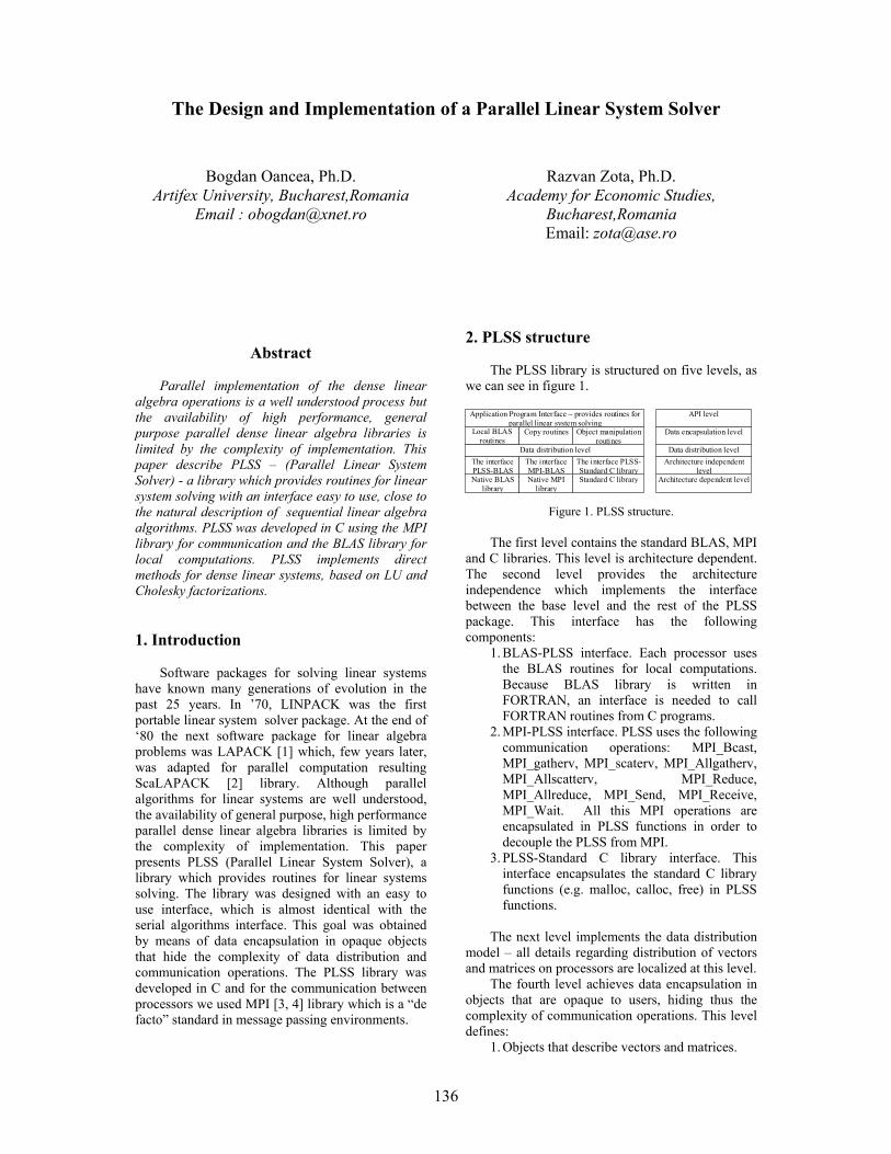
136
The Design and Implementation of a Parallel Linear System Solver
Bogdan Oancea, Ph.D. Artifex University, Bucharest,Romania
Email : [email protected]
Razvan Zota, Ph.D. Academy for Economic Studies,
Bucharest,Romania Email: [email protected]
Abstract
Parallel implementation of the dense linear algebra operations is a well understood process but the availability of high performance, general purpose parallel dense linear algebra libraries is limited by the complexity of implementation. This paper describe PLSS – (Parallel Linear System Solver) - a library which provides routines for linear system solving with an interface easy to use, close to the natural description of sequential linear algebra algorithms. PLSS was developed in C using the MPI library for communication and the BLAS library for local computations. PLSS implements direct methods for dense linear systems, based on LU and Cholesky factorizations. 1. Introduction
Software packages for solving linear systems have known many generations of evolution in the past 25 years. In ’70, LINPACK was the first portable linear system solver package. At the end of ‘80 the next software package for linear algebra problems was LAPACK [1] which, few years later, was adapted for parallel computation resulting ScaLAPACK [2] library. Although parallel algorithms for linear systems are well understood, the availability of general purpose, high performance parallel dense linear algebra libraries is limited by the complexity of implementation. This paper presents PLSS (Parallel Linear System Solver), a library which provides routines for linear systems solving. The library was designed with an easy to use interface, which is almost identical with the serial algorithms interface. This goal was obtained by means of data encapsulation in opaque objects that hide the complexity of data distribution and communication operations. The PLSS library was developed in C and for the communication between processors we used MPI [3, 4] library which is a “de facto” standard in message passing environments.
2. PLSS structure
The PLSS library is structured on five levels, as we can see in figure 1.
Native BLAS library
Native MPI library
Standard C library
The interface PLSS-BLAS
The interface MPI-BLAS
The interface PLSS-Standard C library
Data distribution level
Copy routines Object manipulation routines
Application Program Interface – provides routines for parallel linear system solving
Architecture dependent level
Architecture independent level
Data distribution level
Data encapsulation level
API level
Local BLAS routines
Figure 1. PLSS structure.
The first level contains the standard BLAS, MPI
and C libraries. This level is architecture dependent. The second level provides the architecture independence which implements the interface between the base level and the rest of the PLSS package. This interface has the following components:
1. BLAS-PLSS interface. Each processor uses the BLAS routines for local computations. Because BLAS library is written in FORTRAN, an interface is needed to call FORTRAN routines from C programs.
2. MPI-PLSS interface. PLSS uses the following communication operations: MPI_Bcast, MPI_gatherv, MPI_scaterv, MPI_Allgatherv, MPI_Allscatterv, MPI_Reduce, MPI_Allreduce, MPI_Send, MPI_Receive, MPI_Wait. All this MPI operations are encapsulated in PLSS functions in order to decouple the PLSS from MPI.
3. PLSS-Standard C library interface. This interface encapsulates the standard C library functions (e.g. malloc, calloc, free) in PLSS functions.
The next level implements the data distribution
model – all details regarding distribution of vectors and matrices on processors are localized at this level.
The fourth level achieves data encapsulation in objects that are opaque to users, hiding thus the complexity of communication operations. This level defines:
1. Objects that describe vectors and matrices.
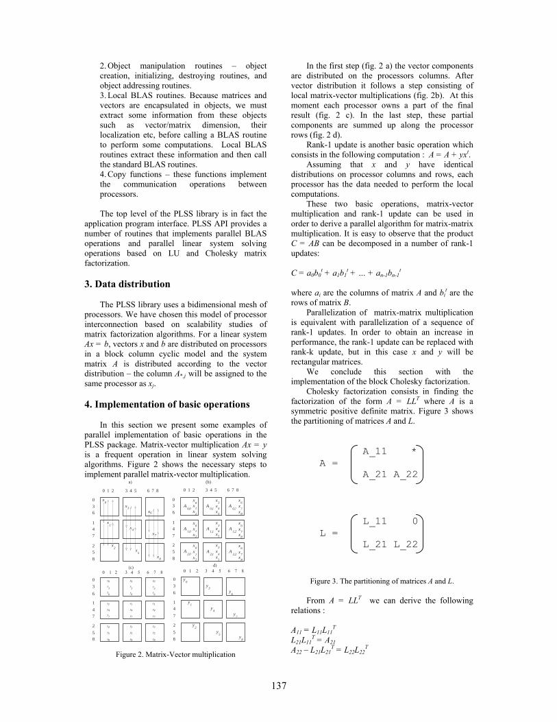
137
2. Object manipulation routines – object creation, initializing, destroying routines, and object addressing routines. 3. Local BLAS routines. Because matrices and vectors are encapsulated in objects, we must extract some information from these objects such as vector/matrix dimension, their localization etc, before calling a BLAS routine to perform some computations. Local BLAS routines extract these information and then call the standard BLAS routines. 4. Copy functions – these functions implement the communication operations between processors. The top level of the PLSS library is in fact the
application program interface. PLSS API provides a number of routines that implements parallel BLAS operations and parallel linear system solving operations based on LU and Cholesky matrix factorization. 3. Data distribution
The PLSS library uses a bidimensional mesh of
processors. We have chosen this model of processor interconnection based on scalability studies of matrix factorization algorithms. For a linear system Ax = b, vectors x and b are distributed on processors in a block column cyclic model and the system matrix A is distributed according to the vector distribution – the column A*,j will be assigned to the same processor as xj.
4. Implementation of basic operations
In this section we present some examples of parallel implementation of basic operations in the PLSS package. Matrix-vector multiplication Ax = y is a frequent operation in linear system solving algorithms. Figure 2 shows the necessary steps to implement parallel matrix-vector multiplication.
3 4 5 6 7 80 1 2
x
x
x
x
x
x
x
x
x
0
1
2
3
4
5
6
7
8
0
36
14
7
25
8
a)
0 1 2 3 4 5 6 7 8
x0
xx
xxx
xxx
1
2
3
4
5
6
7
8
x0
xx
xxx
x
xx
1
2
3
4
5
6
7
8
x0
xx
1
2
03
6
14
7
2
5
8
(b)
A A A0,0
A1,0
A A
A2,0
A A
1,1
2,1
1,2
0,1 0,2
2,2
xxx
xxx
3
4
5
6
7
8
y
y
y0
3
6y
y
y0
3
6y
y
y0
3
6
y
y
y
4
7
1
y
y
y2
5
8 y
y
y2
5
8
y
y
y
4
7
1
y
y
y2
5
8
y
y
y
4
7
1
0
3
6
1
4
7
2
58
(c)0 1 2 3 4 5 6 7 8
0
3
6
1
4
7
2
5
8
y
yy
yy
y
y
yy
0
3
6
14
7
2
5
8
d)
0 1 2 3 4 5 6 7 8
Figure 2. Matrix-Vector multiplication
In the first step (fig. 2 a) the vector components are distributed on the processors columns. After vector distribution it follows a step consisting of local matrix-vector multiplications (fig. 2b). At this moment each processor owns a part of the final result (fig. 2 c). In the last step, these partial components are summed up along the processor rows (fig. 2 d).
Rank-1 update is another basic operation which consists in the following computation : A = A + yxt.
Assuming that x and y have identical distributions on processor columns and rows, each processor has the data needed to perform the local computations.
These two basic operations, matrix-vector multiplication and rank-1 update can be used in order to derive a parallel algorithm for matrix-matrix multiplication. It is easy to observe that the product C = AB can be decomposed in a number of rank-1 updates: C = a0b0
t + a1b1t + … + an-1bn-1
t where ai are the columns of matrix A and bi
t are the rows of matrix B.
Parallelization of matrix-matrix multiplication is equivalent with parallelization of a sequence of rank-1 updates. In order to obtain an increase in performance, the rank-1 update can be replaced with rank-k update, but in this case x and y will be rectangular matrices.
We conclude this section with the implementation of the block Cholesky factorization.
Cholesky factorization consists in finding the factorization of the form A = LLT where A is a symmetric positive definite matrix. Figure 3 shows the partitioning of matrices A and L.
A_11 * A = A_21 A_22 L_11 0 L = L_21 L_22
Figure 3. The partitioning of matrices A and L.
From A = LLT we can derive the following
relations : A11 = L11L11
T L21L11
T = A21 A22 – L21L21
T = L22L22T

138
If matrix L will overwrite the inferior triangle of
A, then the Cholesky factorization consists in the following three computations: A11 ← L11 = Cholesky(A11) (1) A21 ← L21 = A21L21
-T (2) A22 ← A22 –L21L21
T (3)
The dimension of matrix block A11 is computed such that A11 will be stored on only one processor and the factorization from relation (1) will be a local operation. Under these conditions A21 is stored on the same column of processors and L11 will be distributed to these processors in order to solve equation (2). The parallel Cholesky factorization can be described as follows:
1. Determine the block size such that A_11 is stored on a single processor. 2. Split matrix A into blocks A_11, A_21, A_22 according to the block size computed in step 1. 3. Compute the Cholesky factorization of submatrix A_11 – this is a local operation. 4. Distribute A_11 on the column of processors. 5. Solve the triangular system given by equation 2 – this is a local operation because A_11 was distributed in the pervious step to all processors that participate in this computation. 6. Compute the symmetric rank-k update given by equation (3). 7. Recursive apply the same steps to matrix A_22.
The current version of the PLSS package
implements the following parallel BLAS operations: int Axpy( Object alpha, Object x, Object y)
computes yxxy += α
int Dot(Object x, Object y, Object alpha)
computes the dot product yxT=α
int Nrm2( Object x, Object alpha)
computes the euclidian norm of vector x.
int Scal(Object x, Object alpha)
- scales vector x : xxx α=
int Iamax(Object x, Object k, Object xmax)
- computes the maximum value (xmax) and the global offset (k) from object x.
Tabel 1. Level 1 BLAS operations
int Ger ( Object alpha, Object x, Object A)
-computes AxyA T += α
int Gemv (int transa, Object alpha, Object A, Object x, Object beta, Object y)
-computes the matrix-vector multiplication :
yAxy βα +=
int Symv (int uplo, Object alpha, Object A, Object x, Object beta, Object y)
-computes the matrix-vector multiplication for symmetric matrices : yAxy βα +=
int Trmv (int uplo, int trans, int diag, Object A, Object x)
-computes the matrix-vector multiplication for triangular matrices
int Trsv (int uplo, int trans, int diag, Object A, object x)
-solves the linear system Ax=b where A is a triangular matrix
Table 2. Level 2 BLAS operations
int Syrk (int uplo, int trans, Object alpha, Object A, Object beta, Object C)
-symmetric rank-k update :
CAAC T βα +=
int Trsm (int side, int uplo, int trans, int diag, Object alpha, Object A, Object C)
-solves the multiple right hand linear system AX = B
Tabel 3. Level 3 BLAS operations
The name of routines and the significance of
parameters trans, side, uplo, diag, are the same as in the original BLAS library.
For matrix factorization PLSS library has two routines: Cholesky(Object A) – computes the Cholesky factorization of a SPD matrix A. LU(Object A, Object pivots) – computes the LU factorization with partial pivoting. 5. Conclusions
We have developed a library (PLSS - Parallel Linear System Solver) that implements parallel algorithms for linear system solving. Because of the complexity of parallel algorithms it is difficult to design an easy to use parallel linear system solver. The PLSS infrastructure was designed to provide users a simple interface, close to the description of the serial algorithms. This goal was achieved through data encapsulation, hiding the complexity of data distribution and communication operations from users. PLSS was developed in C using MPI and can be run on many different kinds of parallel computers – it can be run on real parallel computers as well as on simple cluster of workstations 6. References

139
1. E. Anderson, Z. Bai, J. Demmel, J. Dongarra, J. Du Croz, A. Greenbaum, S. Hammarling, A. McKenney, S. Ostrouchov, D. Sorensen. LAPACK Users’s Guide. SIAM, Philadelphia, 1992. 2. J. Choi, J. Dongarra, R. Pozo, D.W. Walker. ScaLAPACK : a scalable linear algebra library for distributed memory concurrent computers. Proceedings of the fourth Symposium on the Frontiers of Massively Parallel Computers, IEEE Comput. Soc. Press, (120-127), 1992. 3. W. Gropp, E. Lusk, A. Skjellum. Using MPI : Portable Parallel Programming with the Message-Passing Interface. The MIT Press, Cambridge, Massachusets, 1994 4. M. Snir, S.W. Otto, S. Huss-Lederman, D.W. Walker, J. Dongarra. MPI: the Complete Reference. The MIT Press, 1996. 5. G.H. Golub, Ch. Van Loan. Matrix Computations. Johns Hopkins University Press, 1996. 6. J. Dongarra, J. Du Croz, S. Hammarling and I. Duff, A set of level 3 basic linear algebra subprograms, ACM Trans. Math. Soft., 16(1):1-17, 1990. 7. J. Dongarra, J. Du Croz, S. Hammarling and R. Hanson, An extended set of FORTRAN basic linear algebra subprograms. ACM Trans. Math. Soft., 14(1) 1-17, March, 1988. 8. C.L. Lawson, R.J. Hanson, D.R. Kincaid and F.T. Krogh. Basic linear algebra subprograms for FORTRAN usage. ACM Trans. Math. Soft., 5(3) 308-323, 1979.

140
The Key Technologies behind the Business and Educational Presence on Web;
an OS and Web Server Approach in SMEs and Romanian Educational Institutions
Iulian Oprea Alexandru Ioan Cuza University of Iaşi,
Faculty of Economics and Business Administration, Department of Business
Information Systems [email protected]
Denisa Neagu Alexandru Ioan Cuza University of Iaşi,
Faculty of Economics and Business Administration, Department of Business
Information Systems [email protected]
Abstract
Every race, no matters where is happened to be, depend today on technology. Either we speak about business, education or health care, the Internet has become part of our life in every aspects. Today, to be means not to be outside the Net. This paper tries to see behind scene and to identify the pillars of the web presence in SMEs and in private and public Romanian universities.
1. Introduction
The analysis of presence on the Internet is focus on Romanian public universities, private universities but accredited by the Romanian Minister of Education and Research meaning academic domain, global IT businesses with the best economic results at the end of 2002, top 50 American SMEs and top 50 Romanian SMEs∗, meaning economic environment. Samples use in this case study is, in our opinion, representative: all public and private Romanian universities, best 50s global companies, best 50s Romanian SMEs.
We have study these organizations from many points of view organized in the next categories:
1. organizations with no presence on web; 2. entities who are on web by:
a. web page hosted on somebody else's web site;
b. web site hosted by other; c. in-house hosting;
∗ top 50 Romanian SMEs was based on economic results on year 2001 – www.ccir.ro
d. mixed hosting. In view of down time of web server, organizations
have found a way to manage this problem. The solution is represented by mixed hosting, exactly, if personal web server is down, the web site availability is ensured by the joint web server, and this can be realize in the shortest time so organization web presence is continue.
Joint web server can be met in universities case. The economic organizations or IT business try to avoid this solution because it involves higher level of security.
The web presence is analyzed from multiple points:
1. presence type on the web (external hosting, in-house hosting or mixed hosting);
2. web server type ; 3. operating system. The tools used for this research was search
engines, such as: Google and Netcraft (specialized on site examination).
Data sets for our analyses come from Romanian economic sites (Chamber of Commerce and Industry of Romania) and global sites (Fortune – specialized in economic tops based on various criteria). 2. Romanian academic area
Academic life in Romania is divided in three parts:
1. public universities; 2. accredited private universities; 3. non - accredited private universities. We have included in our study only first two
cases.

141
2.1. Romanian public universities
Romanian public universities as web presence criteria are presented in figure number 1:
Romanian public universities - Web presence
64%
9%
7%
11%
9%
No w eb presence
No active
In-house hosting
Mixed hosting
External hosting Figure 1. Romanian public universities – Web presence
As can see, personal web server represented the greatest weight (37 universities from 50 - 64%). In the second place is joint web server (6 cases – 9%). The figure presents in the same time universities witch don’t have a web address or are not responding.
By applying the OS criteria on universities analysis we found out that Linux as OS it is used in 29 universities (78%). Other academic entities use more Windows in place of Solaris or others operating systems (such as: NetBSD/OpenBSD, Compaq Tru64, FreeBSD). This situation is presented in figure number 2:
Romanian public universities - OS criteria
78%
8%
3%
11%
LinuxWindowsSolarisOther Unix Flavor
Figure 2. Romanian public universities – Os criteria
The results of server criteria are presented in figure number 3, which reflect the greatest weight of
Apache Server (in 33 universities – 89%) against Microsoft or Netscape-Communications servers.
Romanian public universities - Web server
89% 8%
3%
ApacheMicrosoftNetscape-Communications
Figure 3. Romanian public universities – Web server
2.2. Romanian private universities
We have analyzed the case of private universities
by web existence based on web presence criteria and the result is represented in figure number 4.
Romanian private universities - Web presence
28%72%
No web presenceExternal hosting
Figure 4. Romanian private universities – Web presence
From 18 private universities, external web server hosts are 13 (72%) and 5 universities don’t have web presence. External web server is, in most cases, Apache Linux.

142
3. Economic area 3.1. Best global IT businesses
We study these businesses based on two criteria,
such as: Web server presented in figure number 5 and OS presented in figure 6.
Best E - players - Web server
30%
30% 10%
30%
ApacheMicrosoftNetscapeOthers
Figure 5. Best E-players –Web server
Web servers used by business IT are, in the same proportion: Apache, Microsoft and Netscape. Category “others” includes: Roxen, 1.2alpha12, WebLogic, AOLserver.
IT businesses used mostly as OS for web presence Solaris (62% from cases). OS used are also Windows (26%), Linux (6%) or others OS such as: AIX, IRIX, FreeBSD.
Best E - players - OS criteria
62%
6%
26%
6%SolarisLinuxWindowsOther Unix flavour
Figure 6 Best E-players –OS criteria
3.2.Best 50 American SMEs
Based on web presence criteria we find out that American SMEs are in the next situation (figure number 7)
American businesses - Web presence
2%
14%
8%
76%
No web presenceIn-house hostingMixted hostingExternal hosting
Figure 7. Web presence for best 50s American SMEs
From all the 50s American businesses that was represented the sample for study case only one doesn’t have web presence. American business use external hosting in the most of the cases (38 – 76%), but exist businesses that appeal at in-house hosting (7-14%) or mixed hosting (4-8%).
American businesses - Web server
45%
51%
4%
Apache MicrosoftOthers
Figure 8. American Businesses – Web server
The most used web server is Microsoft IIS (25 cases – 51%). In American businesses are used: Apache server in 26 cases - 45%, others such as: Zeus or RapidSite.

143
American businesses - OS criteria
31%
51%
6%
10%
2%
Linux WindowsSolaris FreeBSDIrix
Figure 9. Top 50s American SMEs – OS criteria
As OS for web presence, the greatest proportion is represented by Windows in 25 cases – 51%. Others OS for the same use are: Linux (15 cases- 31%), FreeBSA (5 – 10%), Solaris (3 cases – 6%) or Irix (1- 2%). 3.3. Best 50s Romanian SMEs
In view of web presence criteria, Romanian SMEs case is presented in figure number 10.
Top 50s Romanian SMEs - Web presence
20%
42%
38%
Web page
Web site
No presence on Web Figure 10. Web presence for Top 50s Romanian SMEs
As can see, Romanian SMEs know three situations: they have or web site (42%) or web page (20%) and the third situations, not pleased, no web presence (38%). For the SMEs that has web site, we must say that this is hosted by others. 4. Conclusions
Form all of the cases analyzed result the next conclusions based on each criteria:
1. web presence: a. Romanian Public universities use most
of all in-house hosting; b. Romanian private universities use
external hosting: c. Romanian SMEs are in most cases on
the web by web sites external hosted or presentation page;
d. American SMEs use external hosting in most cases;
2. web server: a. global IT businesses use in the same
proportion Apache, Microsoft and Netscape server;
b. Romanian Public universities and American SMEs use specially Apache server;
3. operating systems: a. global IT businesses use Solaris; b. Romanian Public universities use Linux; c. American SMEs use Windows.
For public universities, Linux, Solaris and other based-UNIX operating systems are still the favorite OS in the academic environment at least at the “presentation” level. High stability and free of charge criteria imposed Linux for this job.
For desktops the situation is quite different. For example in our faculty network with more then 300 personal computers more then 99% use Windows OS. We suspect that behind that all inclusive presence of Linux as a support for web presence, in other universities too, there is a huge disproportion between free operating systems and fee-based operating systems. We think that an honest distribution between these two could save important founds for many universities. The small number of private universities and their poor presence on web reflect that they have a lot to catch up in order to compete on equal basis with public universities.
In business area, particularly SMEs, we found an atypical situation. Even if they have very good financial results, Romanian SMEs, are too few interested in opportunities offered by global market. Both American and Romanian SMEs think in most of the cases that outsourcing the services concerning Web presence are a good idea. 5. References: [1] http://www.ccir.ro [2] http://www.edu.ro/ - public and private
universities list on MEC web site [3] http://www.fortune.com/fortune/Fsb100/0,15254,
,00.html [4] www.netcraft.com
144
Data Mining Approaches for Intrusion Detection in
Email System Internet-Based
Victor-Valeriu Patriciu, Liviu Rusu, Iustin Priescu Military Technical Academy vip, liviur, [email protected]
Abstract
As the Internet grows at a phenomenal rate email systems has become a widely used electronic form of communication. Everyday, a large number of people exchange messages in this fast and inexpensive way. With the excitement on electronic commerce growing, the usage of email will increase more exponential.
In this paper we present our research in developing general method for intrusion detection in email system Internet-based. The main ideas are to use data mining techniques to discover consistent and useful patterns of email system that can recognize anomalies and known intrusions. Key words: security, data mining, intrusion detection, email system 1 Introduction
As the Internet grows at a phenomenal rate email
systems has become a widely used electronic form of communication. Everyday, a large number of people exchange messages in this fast and inexpensive way. With the excitement on electronic commerce growing, the usage of email will increase more exponential.
As network-based computer systems play increasingly vital roles in modern society, they have become the target of our enemies and criminals. Therefore, we need to find the best ways possible to protect our systems. Intrusion prevention techniques, such as user authentication (e.g. using passwords or biometrics) are not sufficient because as systems become ever more complex, there are always system design flaws and programming errors that can lead to security holes [2,4].
One useful method of classification for intrusion detection systems is according to general strategy for detection. There are two categories under this classification [2]: - misuse detection - finds intrusions by looking for activity corresponding to known techniques for intrusion. This generally involves the monitoring of network traffic in search of direct matches to known patterns of attack (called signatures). This is essentially a rule-based approach. A disadvantage of
this approach is that it can only detect intrusions that follow predefined patterns; - anomaly detection - the system defines the expected behavior of the network (or profile) in advance. Any significant deviations from this expected behavior are then reported as possible attacks. Such deviations are not necessarily actual attacks. The primary advantage of anomaly-based detection is the ability to detect novel attacks for which signatures have not been defined.
Another useful method of classification for intrusion detection systems is according to data source. There are two general categories under this classification: - host-based intrusion detection - the data source is collected from an individual host on the network. Host-based detection systems directly monitor the host data files and operating system processes that will potentially be targets of attack. They can, therefore, determine exactly which host resources are the targets of a particular attack; - network-based intrusion detection - the data source is traffic across the network. This involves placing a set of traffic sensors within the network. The sensors typically perform local analysis and detection and report suspicious events to a central location. Since such monitors perform only the intrusion detection function, they are usually much easier to harden against attack and to hide from the attackers. Today’s Internet security systems are specialized to apply a large range of techniques, usually knowledge-based (data mining), to an individual misuse detection problem, such as intrusion, virus or spam detection. Moreover, theses systems are designed for one particular network environment, such as medium-sized network enclaves, and only tap into an individual cross-section of network activity such as email system activity [1].
Table 1 enumerates a range of Internet-based applications for enhancing security. Theses applications cover a set of detection, security and marketing programs that exists within the government, commercial and private sectors. Each of theses applications are within the security capabilities techniques by applying data mining algorithms over appropriate audit data sources.
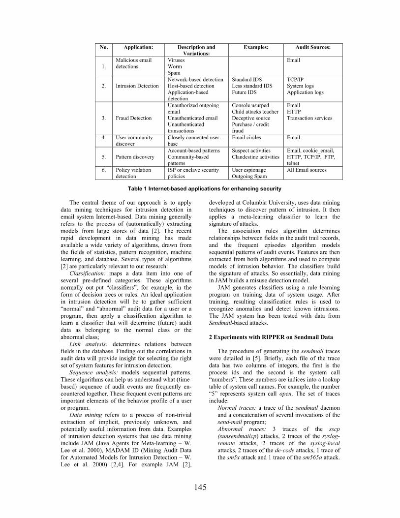
145
No. Application: Description and Variations:
Examples: Audit Sources:
1.
Malicious email detections
Viruses Worm Spam
2.
Intrusion Detection
Network-based detection Host-based detection Application-based detection
Standard IDS Less standard IDS Future IDS
TCP/IP System logs Application logs
3.
Fraud Detection
Unauthorized outgoing email Unauthenticated email Unauthenticated transactions
Console usurped Child attacks teacher Deceptive source Purchase / credit fraud
Email HTTP Transaction services
4. User community discover
Closely connected user-base
Email circles Email
5.
Pattern discovery
Account-based patterns Community-based patterns
Suspect activities Clandestine activities
Email, cookie_email, HTTP, TCP/IP, FTP, telnet
6. Policy violation detection
ISP or enclave security policies
User espionage Outgoing Spam
All Email sources
Table 1 Internet-based applications for enhancing security
The central theme of our approach is to apply
data mining techniques for intrusion detection in email system Internet-based. Data mining generally refers to the process of (automatically) extracting models from large stores of data [2]. The recent rapid development in data mining has made available a wide variety of algorithms, drawn from the fields of statistics, pattern recognition, machine learning, and database. Several types of algorithms [2] are particularly relevant to our research:
Classification: maps a data item into one of several pre-defined categories. These algorithms normally out-put “classifiers”, for example, in the form of decision trees or rules. An ideal application in intrusion detection will be to gather sufficient “normal” and “abnormal” audit data for a user or a program, then apply a classification algorithm to learn a classifier that will determine (future) audit data as belonging to the normal class or the abnormal class;
Link analysis: determines relations between fields in the database. Finding out the correlations in audit data will provide insight for selecting the right set of system features for intrusion detection;
Sequence analysis: models sequential patterns. These algorithms can help us understand what (time-based) sequence of audit events are frequently en-countered together. These frequent event patterns are important elements of the behavior profile of a user or program.
Data mining refers to a process of non-trivial extraction of implicit, previously unknown, and potentially useful information from data. Examples of intrusion detection systems that use data mining include JAM (Java Agents for Meta-learning – W. Lee et al. 2000), MADAM ID (Mining Audit Data for Automated Models for Intrusion Detection – W. Lee et al. 2000) [2,4]. For example JAM [2],
developed at Columbia University, uses data mining techniques to discover pattern of intrusion. It then applies a meta-learning classifier to learn the signature of attacks.
The association rules algorithm determines relationships between fields in the audit trail records, and the frequent episodes algorithm models sequential patterns of audit events. Features are then extracted from both algorithms and used to compute models of intrusion behavior. The classifiers build the signature of attacks. So essentially, data mining in JAM builds a misuse detection model.
JAM generates classifiers using a rule learning program on training data of system usage. After training, resulting classification rules is used to recognize anomalies and detect known intrusions. The JAM system has been tested with data from Sendmail-based attacks. 2 Experiments with RIPPER on Sendmail Data
The procedure of generating the sendmail traces
were detailed in [5]. Briefly, each file of the trace data has two columns of integers, the first is the process ids and the second is the system call “numbers”. These numbers are indices into a lookup table of system call names. For example, the number “5” represents system call open. The set of traces include:
Normal traces: a trace of the sendmail daemon and a concatenation of several invocations of the send-mail program; Abnormal traces: 3 traces of the sscp (sunsendmailcp) attacks, 2 traces of the syslog-remote attacks, 2 traces of the syslog-local attacks, 2 traces of the de-code attacks, 1 trace of the sm5x attack and 1 trace of the sm565a attack.

146
These are the traces of (various kinds of) abnormal runs of the sendmail program [4].
System Call Sequences (length 7) Class Labels 4 2 66 66 4 138 66 “normal” … … 5 5 5 4 59 105 104 “abnormal” … … Table 2. Pre-labeled System Call Sequences of Length 7
In order for a machine learning program to learn the classification models of the “normal” and “abnormal” system call sequences, we need to supply it with a set of training data containing pre-labeled “normal” and “abnormal” sequences. We use a sliding window to scan the normal traces and create a list of unique sequences of system calls. We call this list the “normal” list. Next, we scan each of the intrusion traces. For each sequence of system calls, we first look it up in the normal list. If an exact match can be found then the sequence is labeled as “normal”. Otherwise it is labeled as “abnormal” (note that the data gathering process described in [5] ensured that the normal traces include nearly all possible “normal” short sequences of system calls, as new runs of failed to generate new sequences). Needless to say all sequences in the normal traces are labeled as “normal”. See Table 2 for an example of the labeled sequences. It should be noted that an intrusion trace contains many normal sequences in addition to the abnormal sequences since the illegal activities only occur in some places within a trace.
We applied RIPPER [3,4], a rule learning program, to our training data. The following learning tasks were formulated to induce the rule sets for normal and abnormal system call sequences:
- Each record has positional attributes p1, p2, …, pn one for each of the system calls in a sequence of length n; plus a class label, “normal” or “abnormal; - The training data is composed of normal sequences taken from 80% of the normal traces, plus the abnormal sequences from 2 traces of the attacks, 1 trace of the syslog-local attack, and 1 trace of the syslog-remote attack; - The testing data includes both normal and
abnormal traces not used in the training data. RIPPER outputs a set of if-then rules for the
“minority” classes, and a default “true” rule for the remaining class. The following exemplar RIPPER rules were generated from the system call data:
- normal: p2=104, p7=112; meaning: if p2 is 104 (vtimes) and p7 is 112 (vtrace), then the sequence is “normal”;
- normal: p6=19, p7=102; meaning: if p6 is 19 (lseek) and p7 is 102 (sigvek), then the sequence is “normal”;
- …;
- abnormal – true – meaning: if none of the above, the sequence is abnormal.
These RIPPER rules can be used to predict
whether a sequence is “abnormal” or “normal”. But what the intrusion detection system needs to know is whether the trace being analyzed is an intrusion or not. We use the following post-processing scheme to detect whether a given trace is an intrusion based on the RIPPER predictions of its constituent sequences [4]: 1. Use a sliding window of length (2l+1), 7, 9, 11, 13, etc., and a sliding (shift) step of l, to scan the predictions made by the RIPPER rules on system call sequences. 2. For each of the (length 2l+1) regions of RIPPER predictions generated in Step 1, if more than l predictions are “abnormal” then the current region of predictions is an “abnormal” region. (Note that l is an input parameter) 3. If the percentage of abnormal regions is above a threshold value, say 2% then the trace is an intrusion.
% abn. % abn. in experiments
Traces [5] Frost A B C D sscp-1 5.2 41.9 32.2 40.0 33.1 sscp-2 5.2 40.4 30.4 37.6 33.3 sscp-3 5.2 40.4 30.4 37.6 33.3 syslog-r-1 5.1 30.8 21.2 30.3 21.9 syslog-r-2 1.7 27.1 15.6 26.8 16.5 syslog-l-1 4.0 16.7 11.1 17.01 13.0 syslog-l-2 5.3 19.9 15.9 19.8 15.9 decode-1 0.3 4.7 2.1 3.1 2.1 decode-2 0.3 4.4 2.0 2.5 2..2 sm565a 0.6 11.7 8.0 1.1 1.0 sm5x 2.7 17.7 6.5 5.0 3.0 sendmail 0 1.0 0.1 0.2 0.3
Table 3 Comparing Detection of Anomalies
RIPPER only outputs rules for the “minority” class. For example, in our experiments, if the training data has fewer abnormal sequences than the normal ones, the output RIPPER rules can be used to identify abnormal sequences, and the default (everything else) prediction is normal. We conjectured that a set of specific rules for normal sequences can be used as the “identity” of a program, and thus can be used to detect any known and unknown intrusions (anomaly intrusion detection). Whereas having only the rules for abnormal sequences only gives us the capability to identify known intrusions (misuse intrusion detection).
We compare the results of the following experiments that have different distributions of abnormal versus normal sequences in the training data: Experiment A: 46% normal and 54% abnormal, sequence length is 11;

147
Experiment B: 46% normal and 54% abnormal, sequence length is 7; Experiment C: 46% abnormal and 54% normal, sequence length is 7; Experiment D: 46% abnormal and 54% normal, sequence length is 7; Table 3 shows the results of using the classifiers from these experiments to analyze the traces. We report here the percentage of abnormal regions (as measured by our post-processing scheme) of each trace, and compare our results with Forrest et al., as reported in [5].
From Table 3, we can see that in general, intrusion traces generate much larger percentages of abnormal regions than the normal traces. We call these measured percentages the “scores” of the traces. In order to establish a threshold score for identifying intrusion traces, it is desirable that there is a sufficiently large gap between the scores of the normal sendmail traces and the low-end scores of the intrusion traces. Comparing experiments that used the same sequence length, we observe that such a gap in A 3.4, is larger than the gap in C, 0.9 and 1.19 in B is larger than 0.7 in D.
The RIPPER rules from experiments A and B describe the patterns of the normal sequences. Here the results show that these rules can be used to identify the intrusion traces, including those not seen in the training data, namely, the decode traces, the sm565a and sm5x traces. This confirms our conjecture that rules for normal patterns can be used for anomaly detection.
The RIPPER rules from experiments C and D specify the patterns of abnormal sequences in the intrusion traces included in the training data. The results indicate that these rules are very capable of detecting the intrusion traces of the “known” types (those seen in the training data), namely, the sscp-3 trace, the syslog-remote-2 trace and the syslog-local-2 trace. But comparing with the rules from A and B, the rules in C and D perform poorly on intrusion traces of “unknown” types. This confirms our
conjecture that rules for abnormal patterns are good for misuse intrusion detection, but may not be as effective in detecting future (“unknown”) intrusions.
3 Conclusions
In this paper we present our research in
developing general method for intrusion detection in email system Internet-based. The main ideas are to use data mining techniques to discover consistent and useful patterns of email system that can recognize anomalies and known intrusions. This framework consists of classification, association rules, and frequencies episodes programs that can be used to (automatically) construct detection models.
The experiments on sendmail system call data demonstrated the effectiveness of classification models in detecting anomalies. The accuracy of the detection models depends on sufficient training data and the right feature set. We suggested that the association rules and frequent episodes algorithms can be used to compute the consistent patterns from audit data. 4 References [1] S.J. Stolfo, S. Hershkop, K. Wang, O. Nimeskern, and C.W. Hu, Behavior Profiling of Email, First NSF/NIJ, ISI, 2003; [2] W. Lee, S.J. Stolfo, K.W. Mok, Algorithms for Mining System Audit Data, in Proc. KDD, 1999; [3] W.W. Cohen, Fast Effective Rule Induction, in 12th Conference on Machine Learning, CA, 1995; [4] W. Lee, S. Stolfo, Data Mining Approaches for Intrusion Detection, in 7th Usenix Security, 1998; [5] S. Forrest, S. A. Hofmeyr, A. Somayaji, and T. A. Longstaff, A sense of self for unix processes, in Proc. of the 1996 IEEE SSP, p. 120–128, CA, 1996; [6] V.V. Patriciu, I. Priescu, Using Data Mining Techniques for increasing Security in E-mail System Internet-based, in 11th Conference CAIM, Oradea, 2003.

148
Development of RENAM State and Infrastructure
Erich Peplow Fachhochschule Stralsund
Peter Bogatencov, Tudor Cibotaru, Grigory Secrieru, Veaceslav Sidorenco,
Boris Varzari RENAM
Abstract
The importance of National Research and Educational Networking organizations in building of Information Society increases. Current state and development plans of Research and Educational Networked Association of Moldova (RENAM) are briefly presented. 1. Introduction
Scientific-educational Internet segments are actively developing in all countries and the same situation is the reality for Moldova too. The support of the international organizations and foundations – European Commission, UNESCO, NATO Scientific Committee, Soros Foundation, Eurasia Foundation favors the practical realization of the united initiatives in this sphere in Moldova. As a result of this activity national scale NREN (National Research and Educational Network) RENAM (Research and Educational Networking Association of Moldova) infrastructure continue its development.
The basic propositions of the designed RENAM network creation program assumed implementation of communication highways and access nodes in Chisinau and on the territory of the country, developing of external links to provide reliable connection to Internet.
Networking infrastructure now offers communication capabilities for basic scientific and educational establishments in Moldova and joins main State Universities, more than 20 institutions of ASM, many private higher educational institutions and colleges [1,2].
The Intranet structure of RENAM is intended to solve the following tasks: • creation and distribution of electronic distance
learning and training courses for students from Universities and colleges, for postgraduate students, pupils;
• creation bibliography information exchange, electronic publication availability for all members of scientific-educational community of Moldova;
• distributed information systems implementation for scientific and educational institutions management;
• distributed applied scientific databases creation and exploitation;
• joint projects realization, information project support, establishing necessary contacts with industry and governmental organizations.
2. Development of RENAM
The analysis of the accumulated experience allowed to specialists of RENAM together with the representatives of other research institutions and universities, participating in creation and development of the network, to launch the project of the further improvement of the networking infrastructure and its transition to the new technological basis.
The grounds for RENAM network development are the following: • The growing number of the network
recourses users and their new demands. In 1999, when the initial networking structure was designed it had been estimated that the number of the connected workstations and hosts wouldn’t exceed 700-1000 units. At present total quantity of included in the campuses subnets computers, which utilize RENAM communication highways facilities is over 1800. The dynamics of this growth isn’t decrease, but on the contrary became more intensive at last time.
• The necessity to introduce new perspective networking technologies and services. Modern educational systems deployment requires handle the multimedia applications, on-line interactions with remote tutoring systems and on-line monitoring of student’s knowledge. The new

149
distance learning technologies and applications based on moving objects and voice transmission. All these demands require the increment of a capacity of internal and external communication links, communication equipment possibilities and introducing new communication technologies ensuring utilization Quality of Service regimes within the framework of RENAM network. As the result it will allow applying new popular methods of representation of information, interaction with information resources and also many other modern networking technologies will become available;
• Including into the RENAM networking infrastructure additional state and private universities and principal colleges. Creation of presence nodes in new peripheral points on Moldova territory, where research and educational centers and organizations located (fig.1.);
Figure 1. Planned RENAM main connectivity structure and capacities
• Improvement of Internet connectivity on the
base of the capacity increasing of the existing channels and creation new external links. In particular, providing access into Trans-European network GEANT [3] by realizing the project of direct connection with the scientific and educational network of Romania RoEduNet [4,5].
The existing experience of the analogical academic networking structures implementation shows the perspective of two basic approaches for future RENAM network development. For providing the most effective support of QoS it’s suggested transition to ATM technology within Chisinau RENAM backbone and utilization of new fiber optic communication media for data transfer.
General scheme of ATM fiber optic backbone of the second stage the network developing program is
represented on fig. 2. The kernel of this infrastructure is based on high throughput backbone ATM switch ASX-200BX (Marconi), which offer possibilities to organize up to 32 connections including OC3 155 Mbps capacity links.
Figure 2. General scheme of ATM fiber optic backbone
Dark fiber highways will cover the most
intensive traffic points and this fiber channels structure allows to establish 100-155 Mbps interconnections among all principal nodes of the network. The creation of the own fiber optic communication medium is economically and technically grounded, that could be explained by the following causes. At present the state telecommunication company has no free fiber optic channels to ensure the connection of all new creating nodes of RENAM network. At the same time the leased fiber optic channels annual rent is commensurable with the cost of the own independent fiber optic mains construction, so the investments into creation of new fiber optic mains for RENAM networking infrastructure are economically expedient.
The successful realization of the new program of development of a network RENAM will allow to expand essentially the area of scientific - educational establishments, that will use modern communication opportunities of a network, will promote development and wide penetration of new educational technologies. As a result it will become possible to decrease the specific charges on operation of a network, will enable to establish a parity information exchange with the colleagues from other countries.
Improvements of external Internet connectivity are made now on the base of the capacity increasing of the existing channels, creation of new VSAT and other external links and, in particular, providing access to GEANT Trans-European network by realizing the project of direct connection with the scientific and educational network of Romania RoEduNet. Connecting RENAM with URAN: the NREN of Ukraine – were focal negotiation subjects of NATO and CEENET joint International seminar

150
held in Kiev City (Ukraine) at the beginning of April 2003 [6]. 3. RENAM obtained the NREN status
The Ministry of Education of Republic of Moldova, the Department of Informational Technologies of Moldova, the Academy of Sciences of Republic of Moldova, State Superior Council of Science and Technology Development, State University of Moldova, Technical University of Moldova (Sides) had accepted in year 2002 the agreement about following: • Sides realize the importance of promoting of the
research and educational institution’s collaboration with the aim of coordination and consolidation of joint efforts in foundation of developed informational media of the science-educational community of Moldova. It is an essential element of the social progress and the development of the Informational Society in Moldova.
• Taking in consideration the positive practice of the European countries, Sides promote and distinguish as the main subject of this agreement the creation of the necessary premises for continued and efficient development of the existent academic scientific-educational data network - the joint strategic platform for building of informational system for the whole area of the science and education community of Moldova, integrated into European and world informational system. Having this aim the Sides accept following:
o To consider the opportune creation of the NREN (National Research and Education Network) of Moldova as a joint structural base in the creation and development of the infrastructure of the specialized informational network for the branch of the science and education.
o To assign the functions of NREN of Moldova to existent network named RENAM (Research and Educational Networking Association of Moldova), represented by the RENAM Association and created on the NATO Scientific Council’s base of grants and other international organisms with the aim of providing the scientific-educational societies of Moldova with a developed infrastructure of data communications network.
o To create the Coordination Council of the NREN, which consists of the representatives of the Sides with the functions of generation of joint initiatives of planning, coordination and appreciation of the realizes, accenting the importance of
the agreed elaboration of the national and international projects wit the aim of the efficient utilization of the human, material and financial resources, orientated to the development of the informational corporate branch of the science and education of Moldova.
• Sides supports the activities of the cooperation in the field of the information technologies having the aim to provide the help of the international organisms in active integration of Moldova in the scientific-educational and world international area with the access to GEANT and other transeuropean networks. The NREN status of RENAM was recognized by
TERENA (see TERENA Compendium published on [7]).
RENAM also becomes member of CEENet: Central and Eastern European Networking Association [8].
4. RENAM and preparation of WSIS
It is broadly recognized that information is a powerful tool for economic and social development. Information revolution affects the way people live, learn and work and how governments interact with civil society. A crucial change from an industrial to information-based society is observed now.
The accelerating convergence between telecommunications, broadcasting multimedia and information and communication technologies (ICTs) is driving new products and services, as well as ways of conducting business and commerce.
The World Summit on Information Society (WSIS: http://www.itu.int/wsis) will provide a unique opportunity for all key players to contribute actively to bridge the digital and knowledge divides. The Summit has been endorsed by the UN General Assembly as an effective means to assist the United Nations in fulfilling the goals of the Millennium declaration. The Millennium Summit recognized the key role of partnerships involving governments, bilateral and multilateral development agencies, the private sector, civil society and other stakeholders in making ICTs an important component for sustainable development.
ITU is the leading UN agency with the scientific, technical, economic and policy expertise capable of helping world leaders, the private sector, and the NGO community formulate and implement a shared vision for utilizing ICTs for connecting marginalized communities to the Information Age. In 2001, the ITU Council decided to hold a Summit in two phases with the first phase to be held from 10 to 12 December 2003, in Geneva, Switzerland and the second in 2005 in Tunis, Tunisia. The UN General Assembly Resolution 56/183 endorsed the framework for the Summit adopted by the ITU

151
Council. The first phase of the Summit in Geneva in 2003 will create a common vision and action plan on how to deal with the new challenges of the ever-evolving information society, specifically identifying ways to help close the gap between the "haves" and "have nots" of access to the global information and communication network (fig3.).
Figure 3. WSIS preparatory process The second phase in Tunisia in 2005 will
reassess that plan and generate additional action if necessary. A High-Level Summit Organizing Committee (HLSOC) has been established under the patronage of Kofi Annan, UN Secretary-General.
Its purpose is to coordinate the efforts of the international United Nations family in the preparation, organization and holding of WSIS. The Executive Secretariat WSIS/ES was established under the authority of the HLSOC to assist in the preparation of the Summit. It is based at the ITU headquarters in Geneva. Regional Conferences had produced very important set of draft documents: • Africa: Bamako Declaration WSIS/PC-
2/DOC/4, 28-30 May 2002 • Europe: Bucharest Declaration WSIS/PC-
2/DOC/5, 7-9 November 2002 • Asia-Pacific: Tokyo Declaration WSIS/PC-
2/DOC/6, • Latin America & Caribbean: Bávaro
Declaration WSIS/PC-2/DOC/7, 29-31 January 2003
• Beirut Declaration WSIS/PC-2/DOC/8 During preparatory meetings PrepCom 1
(Geneva 1-5 July 2002) and PrepCom 2 (Geneva 17-28 February 2002) had been produced draft Declaration and Action Plan and had been consolidated Civil Society around CS Bureau, formed of delegates from different “families”.
RENAM was accredited by Civil Society Secretariat for WSIS preparatory process [9]. Delegates from RENAM had participated at the work of Pan European WSIS preparatory
Conference (Bucharest, 2002) and PrepCom2 Conference (Geneva, 2003). 5. References [1] Peplow E., Secrieru G., Bogatencov P., Varzari B., Sidorenco V, Fedeashin I. RENAM: National Research and Educational Networking Association of Moldova. Acta Academica 2001. International Informatization Academy, Branch of R. Moldova, Chisinau, "Evrica", 2001, pp. 57-65. [2] Andries A., Bostan I., Bogatencov P., Cibotaru T., Secrieru G., Sidorenco V., Varzari B. Academic Network Development Projects Realization in Moldova. In: Abstracts of the International Conference “Information Technologies-2002 (Bit+2002)”, Chisinau, 2002. [3] GEANT - The pan-European Gigabit Research Network http://www.dante.net/geant/geant-brochure.html [4] Romanian Education Network (RoEduNet). http://www.roedu.net [5] Peplow E, Rusu O., Secrieru G., Bogatencov P., Sidorenco V., Varzari B., Pascal V. RoEduNet-RENAM: a Project of fast Backbone Link between National Academic Networks of Romania and Moldova. Proceedings of First RoEduNet Conference. Cluj. 2002. [6] Ukrainian Research and Academic Network. http://www.uran.net.ua [7] Compendium 2003 - RENAM - Basic Information. http://www.terena.nl/compendium /2003/basicinfo.php?nrenID=30 [8] CEENet. Central and Eastern European Networking Association. List of the CEENet member countries. Moldova. http://www.ceenet.org/ Moldova.html [9] Accreditation of NGOs, Civil Society and Business Sector Entities to the WSIS. WSIS/PC-2/DOC/0009. http://www.itu.int/dms_pub/itu-s/md/03/wsispc2/doc/S03-WSISPC2-DOC-0009!!MSW-E.doc

152
A European Comparison of ICT Qualification Strategies in Training Institutions, Colleges, Universities and Vocational schools
Dr. Eugen Petac Foundation for Promoting ICT
Munteanu Dragos Foundation for Promoting ICT
Abstract
This paper describes and analyses practical implementation of ICT (Information and Communications Technology) training profiles and ICT qualification strategies in training institutions, colleges and vocational schools for some European countries: Czech Republic, Germany, Netherlands, Portugal and Romania. This work is part of EUQuaSIT (www.euquqsit.net) - a European project that aims at contributing to the transparency of ICT work and qualification, funded by the European Commission, Leonardo da Vinci II project, 2001-2004. The project also intends to analyze the specific demands of companies within their ICT workforce and to what extend different vocational training strategies in partner countries fulfill their needs.
Fields of study: VET and CVT training institutions, colleges, universities and vocational schools that plan and undergo ICT qualifications. Objectives: Systematic processing of vocational education and training profiles in ICT. European comparison of the practical implementation of training profiles and ICT qualification strategies in VET and CVT training institutions, colleges and universities.
1. EUQuaSIT – a European Project in ICT field with Romania as partner
EUQuaSIT – European Qualification Strategies
in Information and Communications Technology (www.euquasit.net) is a transnational project being carried out since 2001 involving partners of five European countries: The National Institute of Technical and Vocational Education, Weilova, Praha, Czech Republic, http://www.nuov.cz; Berufsbildungsinstitut Arbeit und Technik, University Flensburg, Germany (project coordinator), http://www.biat.uni-flensburg.de; Bundesinstitut für Berufsbildung, Bonn,Germany http://www.bibb.de; VEV International -Nijkerk, Netherlands, http://www.vev.nl; Tecnoforma, S.A. Almada, Portugal, [email protected]; Central Systems, Foundation for Promoting ICT,
Constantza, Romania, http://www.central-systems.ro, http://fict.ro; Danubius University, Galati, Romania, http://www.uni-danubius.galati.ro. EUQuaSIT is funded by the European Commission, Leonardo da Vinci II project, 2001-2004.
The project is aiming at systematic collections of structural material, statistical data and empirical analysis of various national ICT qualification strategies within the system of initial and continuing vocational education and training (VET, CVT) taking into account possibilities in higher education (HE). Major objective is finally an international comparison of national qualification strategies within the systems of initial and continuing vocational education and training aiming at the identification of synergies and alternatives from a European point of view.
Correspondingly there is a need for investigations, evaluation and international comparison on ICT working areas and its interaction with the practical organization and implementation of qualification strategies and training in companies and training institutions in the field of ICT. The objective of the project is to focus on this interaction in order to allow comparable research outcomes in a European context that sufficiently consider companies’ demand of ICT specialists and professionals and acceptance of corresponding ICT qualification profiles. Although, however, used ICT technologies are supposed to be similar in most of the European countries it can be presumed that work processes are organised in more or less different ways, depending on the country, the region, the size of companies etc., probably especially in the field of ICT. Furthermore various results of studies carried out in the past indicated that the systems and therefore qualification strategies in European countries differ considerably.
Based on the objectives and the partnership of EUQuaSIT the following target and beneficiary groups are addressed: companies of various sectors and size, especially small and medium sized enterprises (SMEs) vocational schools, colleges and other training institutions committed in ICT qualification and training, ICT professionals and specialists as well as students, trainees and apprentices, institutions and individuals committed

153
in ICT training for disadvantaged groups, European, national and regional policy makers in vocational education and training in the field of ICT, social partners and other organisations related to vocational education and training in the field of ICT, e.g. Chambers of Commerce.
2. Education and vocational training in Romania 2.1. Basic principles concerning education
According to Education Act 84/1995, education is a national priority and should contribute to a free and harmonious development of the individual and
of students’ autonomous and creative personality development. In 1995 Romanian Parliament adopted a new education law, designed to offer the legislative framework necessary for an overall reform of the education system in Romania. The reform aims at two components of the system: primary and secondary education - on one side, higher education - on the other side. The Teaching Staff Regulation, promulgated in June 1997 by Romanian Parliament regulate the appointment, transfer, dismissal and retirement of teaching and non-teaching staff, completing the reform in this respect. The basic structure of the Romanian education system is presented in Figure 1.
Figure 1. Education System in Romania

154
2.2. Vocational Education and Training
VET in Romania is developed according with the requirements of a democratic society, of the market economy, based on regional and local labour market needs and a purpose to facilitate the economic restructuring process. The strategy for VET development takes into account the best practices and the tradition in Romania, as well as the achievements and the development tendencies of these forms of education in the European Union countries and in the word.
According with the Law of Education, the VET takes place in: vocational school, apprentice school, technological high school, post high-school and foreman school.
The vocational and post-high schools have been reformed within the Phare VET RO 9405 Program developed in 25 pilot schools and 50 demonstration schools for 20 occupational families that cover all the economic sectors. Starting with the 1999-2000 school year, the achievements of this program were generalised in the whole national system of education. At beginning of 1998, it was for the first time that the reform of the technical vocational education was systemically approached. Therefore, the high school and the apprentice school were adjusted, according with the overall educational system aims, based on the VET reform program principles. Consequently, 1999-2000 school year represented a milestone in the implementation of the reformed VET system, with the related institutional arrangement.
The involvement of social partners in the development of training standards, local developed curriculum, information and career counsel, certification and educational planning are major achievements in the field of social dialog in VET. For the social partnership in VET were set up National Council for Vocational Education and Lifelong learning and Local Development Committees of the Social Partnership in VET, the latter being organised at the county level, as consultative managerial structures of the School Inspector Body. The sustain ability of above mentioned decisions is ensured by the revised Law of Education No.84/1995, adopted by the Parliament in 1999. 2.2.1. Bodies for standardised qualification. The standardised qualification levels are the first step of the curriculum reform. The standardisation of the qualifications actually represents the occupational analyse of the trades and professions followed by a description on discrete competency units. Responsible for the achievement of occupational analyse is Council for the Occupational Standards and Evaluation (CSOE/COSA) – which has worked at a series of qualifications and professional specialisation, on the basis of the Romanian
Occupations Classification (COR) and sector investigations on recent specialisation, ignored by COR (in the revised work). The Occupational Standards (OS) are the configurations of occupational tasks that are to be evaluated at the work place, and are mainly addressed to the employers (evaluators). The OS represent, at the same time, the valuable structure of contents and capacities that can be used as basis of a continuing education curriculum. The Vocational Training Standards (VTS) adopted in Romania have a mixing formula of the modular occupational model. The construction of the learning process is achieved through the description of the discrete units of each global competencies’ unit, taken from the occupational standard.
The VTS describe the fundamental competencies which are essential (core competencies) for gaining the vocational qualification. These competencies are actualized during the school vocational training and are expressed in three categories of integrated capacities (theoretical and practical):
a. Of knowledge; b. Of practice; c. Social (individual and team). d. Creativity and entrepreneurship abilities, critical thinking, the consciously assumed responsibilities, the civic and community sense, the communication abilities, the team work abilities, the skills needed when solving the problems/conflicts, the ability to develop self and professional capacities which are specific for trades/specialisation represent the key capacities achieved through the VET. The capacities described in the VTS are the subject of the final evaluation and examination. Development of VET is ensured by the setting
up, starting with January 1st, 1999, the National Centre for the Development of Vocational and Technical Education. The Administrative Board of this public institution is formed of representatives from governmental institutions at national level. The consultative managerial structure at national level is formed of the representatives of the social partners. 2.2.2. Places of the VET
1. Vocational School Starting with the school year 1999-2000 there has been generalized the training model developed within the Phare VET reform program, financed by the European Union; vocational school provides VET for future qualified workers in relevant trades on the labor market. Former narrow trade qualification is counteracted through education, by the tree-like structure of the training and the modules like organization of the specialized training, namely:
a. Certifies qualification level 2 admitted in the European labor market;

155
b. The first year: the basic education provides knowledge and functional knowledge and social capacities, as well as general operating capacities, unspecialized; c. The second year: the general education provides knowledge and integrated capacities of scientific, social and technical culture, as well as half-specialized operating abilities (for the profiles where the specialization begins in the second school year); d. The third year: the specialized education provides knowledge and specialized abilities, as well as the particular behavior of social integration and career purchase, for the relevant trades form the national and internal European points of view and for other prior occupations, from the local perspective. The occupational mobility is assisted by the curriculum at the level of the optional training areas; the cross- curriculum areas, which provide the overall vocational behavior (communication, marketing, legislation, European markets, technology's dynamics) and the optional technical areas or for the specialization of the abilities for the basic trade; e. The fourth year (rare cases): the specialized education provides knowledge and specialized technical abilities for the basic trade (this is only the case of specific trades). f. Its training structure and content provides flexibility and mobility on the labor market; g. It ends up with the graduation diploma and the vocational competencies certificate; h. Graduates of vocational school could continue their studies through high school based on a credit scheme.
2. Apprentice School a. Is a pre-qualification level 1 admitted in the European labor market for the students who do not pass the capacity exam or drop the compulsory elementary school and take part in remedial or compensatory educational programmers; b. Is a vocational education system with a status of community administration and development which educates workers-apprentices in the traditional occupations, groups of occupations or trades which are prior to the social and economical development of the local and regional markets; c. Provides mainly occupational practical education; d. The apprentices classes are organized in the schools that, by law, have the recommendation to have contracts of co-operation with the economic agents or at the working place;
e. It lasts 1-2 years, or a non-modular structure, the duration and the school year organization being established together with the economic agents; f. It ends up with a certificate issued after evaluation based on specific occupational standard competencies.
3. Technological High-School a. Is a scientific-type educational system that follows a tree-like structure, focused on prior technological fields, providing a general specialization corresponding to a pre-qualification for level 3, as admitted in the European labor market; b. The frame-curriculum of this branch respects the elaboration principles of the frame-curriculum of the overall high school: cultural hierarchy and selection, functionality, coherency, equal chances, flexibility and curriculum decentralization, social reliability, and decongestion; c. The school-based curriculum becomes in the framework of this branch a local developed curriculum, being elaborated with the participation of the social partners. Based on the local and regional labor market needs; d. Enrolment in this type of education is possible for those having capacity certificate or for the graduates of vocational schools, according with a methodology approved by the Ministry of Education and Research. e. The 9-th year completes the guiding cycle of this stage's career development; f. The 10-th year provides general training for one of the following profiles: services, resources and techniques as general culture knowledge and includes a core-curriculum for the technical knowledge, which should reflect the contemporary orientation of the high technologies; g. The 11-th, 12-th and 13-th (rare cases for daily courses and always for evening classes) years provide knowledge and specific abilities, as well as the particular behavior of social integration and career purchase; h. It ends up with a baccalaureate diploma and a certificate of competences; the baccalaureate diploma gives the chance of continuing the studies in higher education without any access constraints that regard the field of studies.
4. Post High-School a. Develops, by in-depth study and specialization, the training fields of the technological high-school: techniques, services, natural resources and environment, or other non technological fields; b. It certifies qualification level 3 (technicians) admitted in the European labor market;

156
c. The course of this type of school are financed by the beneficiaries, either juridical or physical entities, by contract with the school provider; d. It ends up with a certificate of vocational competencies.
5. Foreman School a. It is organized observing the legal framework in force that specifically regulates the foreman profession as a profession; b. This type of schools is financed by beneficiary, either company or individual, through a contract with the course provider; it ends up with a certificate of vocational competencies.
2.3. Continuing vocational training
As the purpose of continuing vocational training is to harmonize labor market needs with those of the social partners (employers, employees, and job seekers), in the dynamic field of IT&C it is most encountered form of education. There are two major categories of providers of such programs in Romania. 2.3.1 Public sector providers. These include centers subordinate to the Ministry of Education and Research (concerning postgraduate training and master degree in ICT field), and training, retraining and continuing training of unemployed people organized by Ministry of Labor and Social Welfare or by certain institutions of different other ministries in Romania.
ITC courses organized by such institutions regard qualifications that in Romania are not yet standardized by COR, most of them for applications in the economic field, various assisted design fields, also in networking, software applications’ maintenance and development, data communication and Internet.
In this respect, post-graduate training in ITC is opened for those coming from no matter what high education field attended: mechanical, electric, economic, and so on. Near most of important universities in Romania appeared centers for “continuing long life training” which one of education direction is ITC.
The courses provided last three semesters and finish with diploma exams and projects. The diploma granted are issued by Romanian Ministry of Education and Research and they are recognized by the Ministry of Labor and Social Welfare (e.g. for those willing to teach IT in theoretical or technological high schools).
Such universities are those from Bucharest (Polytechnic University, Bucharest State University and the Academy of Economical Sciences), Iasi, Galati, Timisoara, Cluj, Craiova and Constanta. For example, the number of those attending IT
postgraduate courses at “Dunarea de Jos” University from Galati grows from 50 per semester to 250 per semester between 1999 and 2001, in 1 to 4 lines of study (each line comprising around 65 trainee). The courses are not only held locally but also in other major towns of the South-Eastern region of Romania (6 counties). 2.3.2 Private sector providers. These include trade unions, foundations, non-profit NGO’s, enterprises and chambers of trade and industry. Romanian legislation does not require that companies allot funds for their employees’ continuing training, nor are there any financial or managerial incentives to encourage companies in this direction. There are, however, numerous forms of co-operation between training program providers and companies. These relate, on the one hand to components of company development strategies and on the other hand, may sometimes be generated by unforeseen requirements due to market developments.
In broad terms, the following scenarios may be identified: a. Some ministries or institutions may set up or finance their own continuing vocational training structures (specialized services, centers, programs). Participation in such continuing vocational training may be conditions for professional promotion, a requirement for confirmation in a managerial position or a prerequisite for adapting to new social and economic conditions. b. Foreign companies, which have bought state enterprises, establish their own continuing vocational training structures. Almost without exception, after downsizing and restructuring, foreign companies own immediately invest in training and retraining their workforce. In some cases these companies sent their staff to training courses in the country of origin. c. In general, state or private enterprises facing financial difficulties or bankruptcy are not interested in continuing vocational training. Instead, employees with workplaces in threat try to enrich their qualification attending courses organized by local training program providers.
In many cases continuing training courses provide ITC components in their curriculum, focusing on applications specific to the given domain. 2.4. Vocational school certification
The Romanian Government initiated in 1999 the Council for Occupational Standards and Attestation (COSA), to organize CVT in Romania (to serve first of all unemployed people) observing European

157
Occupational Standard
CVT programmes Evaluation and certification
Accreditation bodies for training providers (MEC, MMPS)
Training providers – based on competence
Accreditation bodies for organizations fulfilling
evaluation and certification
Centers for professional evaluation and accreditation
Organizations issuing occupational standards and
evaluating tests
Schools, Universities (public/ private) Commerce Chambers (private)
Employers associations, Union trades (private) Professional associations (private)
Companies (private)
Figure 2. Occupational accreditation and certification.
occupational standards and certification under those standards. The continuous training system, observing occupational standards, is presented below, where MEC is Ministry of Education and Research, MMPS is Ministry of Labor and Social Welfare.
Training providers from public sector are: National Agency for Occupation and Training (ANOFP) – which has subsidiaries in all counties, Centers for Continuous Training near public Universities or Group of schools. Training providers from private sector are: private Universities, Chambers of Industry and Commerce, employers and professional associations, companies and NGOs. Standard courses duration is up to 9 months, in IT and related fields they are shorter (20 days to 6 months). 3. Overview on ICT Education in Romania
ICT courses are delivered beginning with gymnasium, according with the future specialization provided by the schools. 3.1. Gymnasium Level
Teaching Computer Science in gymnasium began in 1993. It was agreed that studying Computer Science in gymnasium must have a prevalent practical character, ensuring the pupils with the minimum computer knowledge and skills. For each
form (year of study) there are 68 classes allotted, that means 2 classes per week (60 classes for teaching/ learning and 8 classes for revision). The main topics are:
a. Basic knowledge about computers, including general description of the hardware device, operating systems (e.g. Windows) and small applications (e.g. Paint, Word, Excel), communications (e.g. Internet); b. A programming language, including graphic facilities. There is allowed to choose between the Basic, Logo and Turbo Pascal programming languages, depending on the teacher's training and on the equipment and software available in school; c. Basic algorithms (numerical and graphical). ICT disciplines are studied as optional in
gymnasium beginning with the 3rd grade and as obligatory, starting from the 6th grade, in the “Technologies” curricular area. 3.2. High school Level
In high schools there are two ways for studying ICT disciplines:
a. in ordinary high schools, as an optional discipline; b. in Computer Science high schools (or Computer Science classroom). For teaching Computer Science in ordinary high
schools 2 hours per week are allotted for each form (9th -to 12th). The schedule ensures on one side the development of an algorithmic thinking and on the

158
other side it endows the pupils with useful knowledge about computers, no matter what direction they will take afterwards. There are two main directions.
The theoretical one includes: The Pascal and C++ programming languages; Fundamental algorithms, including numerical and combinatorial algorithms; General methods for developing algorithms (Greedy, Backtracking, Divide et Impera).
The practical one includes the study of an operating system, a text editor, a spreadsheet and a database (for example by using Works 2000 for Windows).
In Computer Science high schools, 8 classes are allotted weekly for studying Computer Science disciplines, among which 4 for practical training. The basic objectives, which this educational system should achieve, are the following: forming an algorithmic thinking; developing logic modeling abilities; getting familiar with simulation problems; forming the habits of independent work with computers; forming the necessary skill in solving the Computer Science problems; making openings to interdisciplinary; integrating the computers in current activities.
After a basic training of 2 years, the present syllabus offers the possibility of choosing the instruction level for the next 2 years: professional (A level) or non-professional (B level) computer user.
For the 9th and 10th forms a unitary curriculum is suggested, containing basic notions, but at the same time preparing the two directions for the upper form.
The schedule for the 9th form includes: computing systems, PC architecture and Windows operating system; (1 class/week); programming: algorithms, Turbo Pascal and C++ - first part) (3 classes/week); while the schedule for the 10th form includes: programming: Turbo Pascal and C++ - second part (2 classes/week); methods and techniques in programming (1 class/week).
For the professional level the schedule is as follows: A level:
For the 11th form: object oriented programming: the C++ language; (3 classes/week); applied Computer Science: Windows; (1 class/week); assembly language for IBM-compatible PC; (1 class/week).
For the 12th form: databases (FoxPro ); (2 classes/week); applied Computer Science: spreadsheets, editors, networks (1 class/week); numerical analysis; (1 class/week).
Unfortunately for the moment there are no teachers for disciplines (physics, chemistry etc.) able to use computers, so it is not possible to integrate now Computer Science in other disciplines, only one exception: mathematics.
The interest in ICT increased during the last years. More and more children are willing to study
ICT disciplines in school and the their level of teaching is increasing too. 3.3. University Level
ICT courses are given now in all Faculties in Romania. They can be separated in 2 groups:
a. courses for students being not specialists in Computer Science b. courses for specialists in computer data processing and control.
We present below separately these situations. 3.3.1. University program for the students being not specialists in Computer Science. Students in medicine, humanistic sciences (literature, languages, sociology, psychology, or law have courses in order to make students familiar with ICT and with the use of some of the existent software products in their particular area of interest.
More developed programs have the faculties where the mathematical ground permits the introduction of a wide range of notions: all kind of engineers (except electronic and automatic who have a special program provided), economists and mathematicians.
For the engineers a course on Algorithms and Programming is provided in the first year of studies. Techniques in programming with Pascal programming language are studied. Depending on their specialization, students have than courses being connected with professional usage of the computer (CAD/CAM, numerical methods, optimization, circuits designing etc.).
For students in faculties in which economic courses are taught, special programs are provided, the main topics including Databases principles and programming languages (SQL, FoxPro), spreadsheets, and other specific software tools. 3.3.2. University program for the students being specialists in Computer Science. Computer Science specialists are prepared in three kinds of Universities:
a. The Technical Universities (Faculty of Automatics, Computer Science and some sections inside Faculty of Electronics and (Tele)Communications. The program is structured on 5 years of study and finishes by the license exam. The mathematical background is assured by the courses delivered in the first two years (Algebra, Mathematical Analysis, Numerical Analysis and Differential Equations). During the first two years courses as "Programming languages" (C++ and Pascal) and "Techniques in Programming" are provided. Beginning with the 3rd year there are 2 sections: Artificial Intelligence and Computing Systems. Courses of the Artificial Intelligence section include: Optical Processing of the Information;

159
Pattern Recognition and Artificial Intelligence; VLSI designing; Speech processing; Image processing; Wavelet analysis and mathematical modeling; Fault Tolerant Systems ; Networks and Open Systems; Software Engineering. The Computing Systems section includes courses as: Networks; Neural Networks and Fuzzy Systems; Parallel and Distributed Architectures; System Engineering; Specialized Processors; Cryptography. About 30 hours of training/week are provided in both sections. The aim of these programs is to prepare specialists in hardware and software, able to use and develop new technologies. b. The Universities, which generally have Departments of Computer Science inside the Faculties of Mathematics or in the Computer Science Faculties. With one exception, (Iasi, where an independent Faculty of Computer Science developed), inside the Faculties of Mathematics (which belong to the Universities) there are Departments of Computer Science. The studies in these departments continue 4 years and finishes by license exam. A solid base of mathematics is assured by a lot of courses included in the first 2 years: Algebra; Mathematical analysis; Geometry; Complex Analysis; Differential Equations; Numerical Analysis; Probability theory and Statistics; Operation research and Optimization. The first year being common with the students in Computer Science course is provided: Bases of Programming. Elementary techniques of programming, C and Java programming language are studied. Beginning with the second year more specialized courses are included. They can be split in 2 classes: Mathematical foundations of Computer Science; Programming and practical aspects of Computer Science. In the first class (Mathematical foundations of Computer Science) we can include: Algebraic bases of Computer Science; Theory of programming languages; Theory of algorithms, calculability and recursivity ; Calculus complexity; Combinatorics and Graph theory. The second class (Programming and practical aspects of Computer Science) contains courses, which usually have provided practical hours (2 hours/week for each course): Operating Systems (Unix, Windows); Windows Programming; Data Structures; Databases; Artificial Intelligence; Graphics; Networks; Parallel and Concurrent Programming; Neural Networks; Simulation models; Compilers; Cryptography.
Students graduating these sections can be teachers in gymnasium and high schools with the condition of following some courses as: Psychology, Pedagogy, Methods in teaching Computing, a month of practical in a Computer Science high school which finishes with a lesson
that the student has to prepare and teach. Some University has also short-term programs (3 years) in Computer Science (e.g. College of Informatics). The students graduating these studies are better users of different software tools than programmers, the number of practical hours being considerable increased. c. Computer Science Programs for Economists. The program in the so-called Academies of Economic Studies is structured on 4 1/2 years of study and finishes by the license exam. There are two cycles: the first cycle includes the first two years of study, while the second one includes the last 2 1/2 years of study.
a. In the first cycle, the courses in Computer Science are: Bases of Computer Programming; Introduction in Operating Systems; Programming Languages; Introduction in Databases. b. In the second cycle, a more wide range of courses in Computer Science are available, the students being allowed to chose a part of them: Operating Systems; Data Structures; Procedural and Functional Programming Languages; Analysis and Design of Economic Information Systems; Logic and Algorithms; Assembly Languages Software Engineering; Artificial Intelligence and Expert Systems; Multimedia Systems; Networks and Distributed Systems. The graduates of the Academy of Economic Studies are supposed to be able to work as economists in Industry and Companies. Some of them become teachers in High schools, were Databases are studied.
3.3.3. Computer Science program for the holders of Masters Degree. A number of students can continue their studies, after graduating their faculty. The master has a program of one and a half year and finishes with a dissertation. The admission is made on the results of an exam. The courses delivered are strongly dependent on the kind of the University are organizing them. Usually, this kind of studies is choose by students intending to get a Ph. D, degree and/or becoming learning staff in the Universities. 3.3.4. Post Graduate Courses. The new law of education kinds stipulates the possibility of organizing 2 kinds of postgraduate studies:
a. post-graduate courses for improvement of basic knowledge in Computer Science, lasting at most one year. The law stipulates that undergraduate staff should periodically attend such courses. An important role in organizing this activity is the one played by the specialized inspectorates, which monitor all activities related to the improvement of undergraduate staff; b. post-graduate studies for specialization in fields like Computer Science, lasting at least one
160
and a half year. Graduates who benefit from this form of training receive a specialization in a new field. Organizing such Courses would allow people who have graduated faculties of mathematics, but not the Department of Computer Science within those faculties, to receive a specialization in Computer Science, as well as the possibility Computer Science in high schools.
4. Some of EUQuaSIT project results 4.1. Summary and comparison
In Romania, Portugal and Czech Republic compulsory full-time education starts at 6 or 7 years of age and ends at 14 or 16 years. In Germany from the age of 6 till 15 years old (10 years) full-time education, followed by a minimum of three years part-time or full-time education is compulsory. In the Netherlands full-time education is compulsory from the age of 5 till 16 years old (12 years) followed by a minimum of two years part-time or full-time education.
ICT-courses in Germany, Portugal and the Netherlands start from the age when learning (whether on a part-time or full-time basis) is compulsory.
Since vocational ICT-training in Romania and Czech Republic generally starts from the age of 14 till 16 years, the courses there are not compulsory.
The educational systems of the project partner countries have many similarities. One exception being Germany for which various school types already exist from the age of 10. In the Netherlands different school types are available only from the age of 12, (limited to 3 types). In Romania, Portugal and Czech Republic, students have, up till the age of 15, no choice of school type (not taking into account special programs for dropout students).
When comparing the teaching method for vocational education and training, differences become clear. In Romania, Portugal and Czech Republic the main method of teaching is according to a scholastic route, which does not always include a (short) vocational practice period within a company.
In the Netherlands and Germany a scholastic route, as well as a dual route, is available. In Germany however the largest group of youngsters follow a dual route, based on theoretical training of between 8 and 12 hours per week at a vocational school, together with practical training within a company for the remainder of the week. Training programs for a scholastic vocational training of 2 years are available in Germany, but have up till now, not attracted many students.
Students following the dual route in the Netherlands and Germany, have a working
agreement. In the Netherlands they also have a learning agreement.
Within the initial education system of all partner-countries, Germany being partly the exception, the possibility exists for continuation of training in higher education once graduation from one of the vocational school types has been obtained. In order to enter higher (vocational) education in Germany (University of Applied Science), students must either possess a higher education entrance certificate (Hochschulreife) or have to go to a specialized upper secondary school for at least one year which is based on a certain type of vocational training as well.
Portugal, the Netherlands and Czech Republic have a wide offer of initial vocational training possibilities for students who wish to become an ICT-professional:
1. Portugal has three types of ICT-training, all giving a student the opportunity to enter higher education afterwards. The technical school spends only 20% of the three-year training on vocational subjects. Therefore it does not solely aim at providing ICT-professionals for the labor market, but more to give them a basis in which to continue their training at a higher level. The vocational school (Ensino Profissional) - a scholastic route of three years - also leads to ICT-professionals. There is a possibility to follow an apprenticeship (Aprendizagem) for three, sometimes four years, leading to a professional ICT qualification. All training types include vocational practice within a company. 2. The Netherlands has a very flexible system with four end levels and two teaching routes. As the system is quite complex actions are being undertaken to enlarge the transparency. All training types provide a vocational practice period within a company (at least 20%) and are available in scholastic (Beroepsopleidende leerweg) or dual routes (Beroepsbegeleidende leerweg). Starting from the age of 16, students can follow a two, three or four-year training to become an ICT-professional. A four year of training provides qualifications, allowing a student to enter into the labour market or continue on to a higher education level (Hoger beroepsonderwijs). Two and three-year training aims at providing ICT-professionals entry into the labor market. After a two or three-year training, follow-up training possibilities are available in order to reach the same level as the four-year training. With a certificate equaling the level of a four-year training, students can enter the labor market as well as enter into higher education. 3. Czech Republic has several training types in secondary vocational education offering training leading to ICT-professionals. Training to a level 2 or level 3 qualification starts after compulsory education. Level 4 training can be started once

161
level 3 training has been successfully completed. Vocational training at SEDOC level 2 (SOU) and level 4 (VOS) provides vocational practice within a company together with training. The possibility to continue training for higher education exist after graduation of training at level 3 or level 4. Fewer possibilities in training types are offered
by the educational systems of Romania and Germany. Nonetheless, this does not necessarily say anything about the offer of different profiles within this training types:
a. Romania offers only one - scholastic – vocational training type. This training does not however offer vocational practice within a company. After completing vocational training, continuation of study at a higher level is possible. b. Germany has training types for both dual (Berufsausbildung) as well as scholastic teaching route (Berufsfachschule); however the latter lasts only two years and does provide only short vocational practice within a company, making it
not as popular as the dual training path. The dual training method takes three to three-and-a-half years, leading to trained ICT professionals entering the labor market straight away. Also the two-year training aims at providing ICT professionals for entrance into the labor market, but with a lower level of qualification. Often trainees of the type do dual training afterwards which is also the precondition to enter further possibilities of training as a master craftsman or technician.
4.2. The on-line investigation
An important step of EUQuaSIT project was the investigation of available ICT profiles and the further training requirement in ICT. Some of the results offered by the analysis done on ICT training institutions are presented below. The graphs indicate the final results corresponding to the questions asked.
a. Do the training institutions plan to offer other new ICT vocational education and training profiles?
b. Which thematic fields are part and content of your further and continuing vocational training for ICT professionals and the ICT professional groups?

162
c. How does your institution keep the goals and content of ICT education and training up to date (thematic adaptation to the ICT development)?

163
d. When you determine and update the content of ICT education and training, in which areas do you see the biggest problems and challenges concerning level, extension and delimitation?
e. What is the structure and how is your ICT education and training organized? (more than one answer applicable)

164
f. Which are the didactic concepts and methodologies your ICT education and training is based on and taught with?
g. Learning and training equipment especially in the ICT field requires high relevance to the current situation. In which areas of media and requisites do you see the biggest problems and challenges concerning costs, procuring, running, administration and maintenance etc.?

165
h. How do the teachers, trainers and lecturers in the ICT field keep their subject orientated and didactic qualification up to date? (more than one answer applicable)
i. What is the actual female rate of ICT trainees, students and participants in your institution?
j. What do training institutions think about a European standardization of ICT education and training on the different qualification levels?

166
5. Acknowledgements The authors are grateful to the EUQuaSIT project partners; without them the results achieved so far couldn’t have been possible. Prof. Dr. A. Willi Petersen and Mr. Carsten Wehmeyer from the University of Flensburg, Germany, have coordinated with success the development in good terms of the project. 6. References [1] EUQuaSIT (Leonardo da Vinci II project – D/00/C/P/RF/91309), Interim Report, Flensburg University, July, 2002. [2] EUQuaSIT, www.euquasit.net. [3] H. Georgescu, Overview on Computer Science in Romania, Tempus S_JEP 11168-96 (Restructuring of the (re)training of school teachers in Computer Science), Computer Libris Agora, Cluj-Napoca, Romania, 1997. [4] IDC, www.idc.com. [5] Ministry of National Education, The New National Curriculum, Bucharest, 2000. [6] Romanian Ministry of Education and Research, www.edu.ro.

167
An Analysis of ICT Policy and Strategies in Romania in European Context
Dr. Eugen Petac Foundation for Promoting ICT
Dorina Petac Foundation for Promoting ICT
Abstract
This paper describes and analyses the Romanian
Qualifications and Strategies in ICT field in European context. This work is part of EUQuaSIT (www.euquqsit.net) - a European project that aims at contributing to the transparency of ICT work and qualification. It also intends to analyze the specific demands of companies within their ICT workforce and to what extend different vocational training strategies in partner countries fulfill their needs. Objectives: Identifying, structure and classification of ICT working areas in companies; Outcomes of current and future demand of ICT work and qualification and the related ICT professions, occupations and qualification profiles; Identifying companies' ICT business and working processes and the corresponding participation of ICT specialists, focusing on the delimitation and collaboration of academic and non-academic ICT fields of activity; Investigation of the main qualification strategies in companies and ICT training institutions considering the relation to enterprises' ICT work and qualification areas; Detailed analysis on special aspects of the demand of ICT occupations and qualification strategies. Fields of study: Big, medium and small sized companies in various areas of business and trade and various regions.
1. The role of ICT in developing the Informational Society
The term Informational Society describes an economy and a society in which the access, acquisition, storage, processing, transmission, spreading and using knowledge and information plays a decisive role.
The advance towards the Informational Society, based on knowledge, is worldwide considered, as a necessary evolution to ensure the durable development in the context of “new economy”, mainly based on products and intellectual-intensive activities, as well as for achieving an advanced socio-human civilization.
The Informational Society based on knowledge is the progress of technology and of communication and computer applications, but also the integration
of the economic, cultural, ambient and social dimensions.
A structure of the Informational Society is shown in Figure 11. The Informational Society is made of five layers: the users layer, the applications layer, the informational infrastructure layer, the institutional layer and the legislative layer. The applications layer also accentuate groups of distinctive applications: e-Business, e-Learning şi e-Governance, including enterprise services and integrated systems. They have in common platforms based on advanced databases and Internet. The informational infrastructure layer constitutes the support on which the informational society is build: Internet, the core of informational coherence (lists of general interest, base registers *), specific databases of general interest and the ITC industry.
In developing the Informational Society the state has a triple role:
a. Acting as a catalyst, he must be aware of the business environment and the citizens regarding the importance and opportunities offered by the Informational Society; b. As settlement organism, the State must ensure the obedience of the rules and the economic growth; c. As major element on the market, the State
must modernize and update its own operations and improve the interaction between the public and the private sector.
On an international level, the benefits of implementing the informational society forces the governments to pursue with priority the following fields:
a. Developing the informatics culture, training all citizens to ensure their access to the new technology; b. Democratizing the use of information, for the purpose of enforcing and ensuring the right of the citizen to have direct access to information; c. Developing the informational systems of the Public Administration with the main goal to improve the services for the citizens; d. Developing the communication infrastructure, by reaching standards of quality, response time, coverage and availability, cost reduction (minimizing);
1 source: http://www.academiaromana.ro

168
Figure 1. A structure of the Informational Society
d. Developing the trust in the informatics systems, ensuring their security and protection of personal data; e. Developing the electronic commerce for the purpose of profitable participation in the global economy; f. Creating a transparent economic environment for the development and sustenance of businesses, as well as ensuring the administration of public funds and the transparence of their use; g. Developing of a stable and safe society by using ICT in the management of crises, environment protection, and last but not least, by ensuring the social security of the citizens. The politic will for promoting the Informational
Society in Romania is dignified by the specific ICT legislation in force:
a. HG 271/2001 – establishing GPTI with the role of integrator and coordinator of trans-zonal solutions from the IT field; b. Law 332/2001 regarding the promotion of direct investments with significant impact in economy; c. Law 133/1999 concerning the stimulation of private entrepreneurs for establishing and development of Small and Medium Enterprises; d. OUG 65/2001 regarding the constitute and functioning of the industrial parks; e. OUG 94/2001, OG 7/2001 and the orders of application – concerning the tax exemption of programmers; f. Packet of laws for creating the frame that ensures the functioning and the development on good terms of the IT sector: the Law of the electronic signature (Law 455/ 2001); The Law of personal (private) data protection (Law
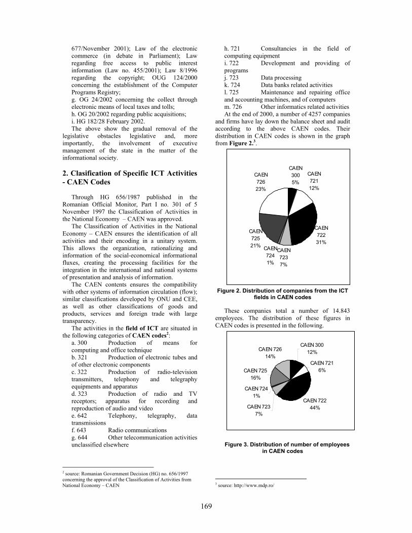
169
677/November 2001); Law of the electronic commerce (in debate in Parliament); Law regarding free access to public interest information (Law no. 455/2001); Law 8/1996 regarding the copyright; OUG 124/2000 concerning the establishment of the Computer Programs Registry; g. OG 24/2002 concerning the collect through electronic means of local taxes and tolls; h. OG 20/2002 regarding public acquisitions; i. HG 182/28 February 2002. The above show the gradual removal of the
legislative obstacles legislative and, more importantly, the involvement of executive management of the state in the matter of the informational society.
2. Clasification of Specific ICT Activities - CAEN Codes
Through HG 656/1987 published in the
Romanian Official Monitor, Part I no. 301 of 5 November 1997 the Classification of Activities in the National Economy – CAEN was approved.
The Classification of Activities in the National Economy – CAEN ensures the identification of all activities and their encoding in a unitary system. This allows the organization, rationalizing and information of the social-economical informational fluxes, creating the processing facilities for the integration in the international and national systems of presentation and analysis of information.
The CAEN contents ensures the compatibility with other systems of information circulation (flow); similar classifications developed by ONU and CEE, as well as other classifications of goods and products, services and foreign trade with large transparency.
The activities in the field of ICT are situated in the following categories of CAEN codes2:
a. 300 Production of means for computing and office technique b. 321 Production of electronic tubes and of other electronic components c. 322 Production of radio-television transmitters, telephony and telegraphy equipments and apparatus d. 323 Production of radio and TV receptors; apparatus for recording and reproduction of audio and video e. 642 Telephony, telegraphy, data transmissions f. 643 Radio communications g. 644 Other telecommunication activities unclassified elsewhere
2 source: Romanian Government Decision (HG) no. 656/1997 concerning the approval of the Classification of Activities from National Economy – CAEN
h. 721 Consultancies in the field of computing equipment i. 722 Development and providing of programs j. 723 Data processing k. 724 Data banks related activities l. 725 Maintenance and repairing office and accounting machines, and of computers m. 726 Other informatics related activities At the end of 2000, a number of 4257 companies
and firms have lay down the balance sheet and audit according to the above CAEN codes. Their distribution in CAEN codes is shown in the graph from Figure 2.3.
CAEN 3005%
CAEN 72112%
CAEN 72231%
CAEN 7237%
CAEN 7241%
CAEN 72521%
CAEN 72623%
Figure 2. Distribution of companies from the ICT fields in CAEN codes
These companies total a number of 14.843
employees. The distribution of these figures in CAEN codes is presented in the following.
CAEN 30012%
CAEN 7216%
CAEN 72244%CAEN 723
7%
CAEN 7241%
CAEN 72516%
CAEN 72614%
Figure 3. Distribution of number of employees
in CAEN codes
3 source: http://www.mdp.ro/

170
The above highlighted companies are those companies that have as main object of activity one of the previous enumerated CAEN categories. Activities in the field of Information Technology are also se deploying in companies that don’t have as main area development of activities according to the previous mentioned CAEN codes.
Of the companies with the above mentioned CAEN codes, 38% are situated in Bucharest, 7,4% in Cluj county, 4,5% in Braşov county, 4,1% in Timiş county, 2,9% in Iaşi county, 2,9% in Sibiu county, 2,6% in Constantza county, 2,6% in Bihor county, 2,3% in Dolj county, the rest of the counties having a percentage below 2%.
According to data provided by the National Institute of Statistics 77% of the total companies presented above are companies with mostly private capital (fund), these making 97% of total exports in this field. 57% of the total number of employees of these companies work in the private sector, those having a 23% greater average rate of salary expenses for an employee then the companies in the field that have mostly state capital.
3. Clasification of specific ICT Occupations in Romania - COR Codes
In commercialism standard classification
systems are used, which constitute the base components of the economic informational system. These constitute themselves in indispensable instruments for ensuring in a unitary manner the gathering, storing, processing and data analysis.
Their ensemble represents the unitary system of classifications and lists, which functions at macroeconomic level.
The elaboration of the new classifications of occupations in Romania (COR) had as a main goal the alignment with the international standards developed by the European Community (ISCO-88-COM) and UN (ISCO-88), thus ensuring the transparence of the social-economic information in the field of resources and using the labor force.
The Classification of occupations is the operation of systematization of occupations (and jobs) of active population, in which an occupation is classified one time only.
Based on HG no. 575 bis/1992, regarding the “Implementing unitary lists of general interest provisioned in the general conception of information in Romania”, the Ministry of Work and Social Solidarity – together with the National Commission for Statistics, the Ministry of Research and Education and the Ministry of Resources and Industries – has the responsibility of developing and “up to date” maintenance of classification of occupations and jobs from Romania.
In Romania, the ICT training is done on different grades of preparation, for the formation of
personnel in occupations with the following in COR codes:
Long-term university studies, with or without a master’s degree:
a. Computers 213101, 213102, 213103, 213104 b. Automatics and industrial informatics 214402 c. Applied Informatics 213101, 213102, 213103, 213104 d. Mecatronics 214406 e. Industrial robots 214402 f. Applied electronics and communications 214406 g. Economical informatics 213101, 213102, 213103, 213104 h. Bookkeeping (Accountancy) and business (commercial) data processing 244109 i. Mathematics + Informatics 232101, 213101, 213102, 213103, 213104 j. Audio-Visual Communications 214406
Short-term university studies: a. Information Technology 213101, 213102, 213103, 213104 b. Computer assisted technologies 213101, 213102, 213103, 213104 c. Office computing 343101 d. Electronic processing of economical data 213101, 213102, 213103, 213104 e. Audio-video, multimedia 214406 f. Technical Informatics 213101, 213102, 213103, 213104
Continuous forming / schools of masters (foreman) – with/without higher (superior) studies in other domains:
a. Computer Consultant 213104 b. System Engineer 213901 c. Databases Administrator 213903 d. Network Administrator 213902 e. Chief-operator in industrial robots 312301 f. Shift leader in computing centers or offices 312202
Post-high school course, refresher course: a. Computing equipments and networks technician 312203 b. Computing systems maintenance technician 312203 c. Technician-operator in industrial robots 312302 d. Analyst-programmer assistant 312102 e. Electronic computer and networks operator 312201
High school – technological or informatics course, vocational school:
a. Programmer assistant 312101 b. Computing equipments electrician-serviceman 724201 c. Electro mechanic networks cables 724404 d. Telecommunications electrician 724407 e. Telecommunications fitter, adjustor; signaling, centralization and blocking installations 724410

171
4. ICT Preparation
As the real evolution of national economy, on a
long, medium and short term evaluation, is clenched in the ties of a „vicious circle” of perpetuation and even deepen the gaps (postponements) of productivity and life standard compared to the European Union, „The medium term National Strategy for economic development of Romania”, proposes itself to ensure the attenuation and the gradual removal of the gaps towards the advanced countries, the modernization of our country keeping pace to the exigencies of transition towards an international-cultural economy where the educational chapter represents the keystone of our social and economic development.
The main purpose in this domain is promoting the educational reform, both at the base level, as well as to the superior level, through modernization of the education system placing the stress on:
a. Decentralization of the national education system; b. Promoting the contractual relationship between the education units and local communities; c. Organization of the national system of forming the managers from the education system; d. Developing and encouraging the use of information technology and communication in the educational process; e. Expanding of the national system of distance education; f. Applying the national program of adult education and the „second chance in education” program; g. Continuous professional forming, in respect with similar policies from EU, creating equal chances of access to information, research, technological-development, education and continuous forming; h. Restructuring of financing in education. Starting from the fact that there is no domain or
field of activity where no processing and no information transmitting is done both inside and outside that particular field, education must be concerned with the gaining of knowledge and skills in using Information Technology and Communications (ICT) by scholars and students. Introduction of ICT in education leads to the development of abilities of using ICT resources, to using these resources in learning other disciplines, to the development of skills related to accessing, interpreting and presenting information, to modeling and event control, to understanding the implications of ITC in society.
In Romania, the ITC training is done in state and private institutions.
Institutions accredited by the Ministry of Research and Education to achieve training in ITC
field are part of the Pre-University and University Education System.
There are private institutions, accredited by the Ministry of Research and Education, by the Center for Training in Informatics or unaccredited, which have in their object of activity ITC training and preparation.
Regardless of the type of institution, state or private, accredited or not, in the perspective of standardization at European level, the ITC training (preparation) is done according to the following levels:
a. Long term university studies, with or without a master degree b. Short term university studies c. Continuous forming / schools of foremen (masters) – with/without higher (superior) studies in other fields d. Post-high school course, refresher course e. High-school – technological or informatics course, vocational school The professional forming programs ensures
the gaining of professional qualifications according to the nation-wide acknowledged occupational standards approved by the Council for Occupational Standards and Certification (COSA), HG 779/1999, act of establishment. COSA, national organism for certification of professional qualifications ensures the quality of the system by authorizing the evaluation centers, by monitoring their activity, by evaluating and certification of evaluators.
According to the proceedings of the Law 151/1999, qualification certificates come as complement of the graduation degrees, which certify the fact that one person followed a training (forming) course and confirms the qualifications gained (obtained).
Professional qualifications are gained through initiation, qualification, specialization, re-qualifications (art. 5), and after sustaining and promoting the evaluation tests (set of practical and/or theoretical tasks) for professional qualifications, certificates are issued as follows: (art.30, 31)
a. certificates of professional qualification for initiation strategies and courses; b. certificates of professional qualification for qualification or re-qualification courses; c. certificates of professional qualification for perfection or specialization strategies and courses; d. certificates of professional qualification for apprenticeship courses at place of employment; The Decree provides (art.31, pct.3), that in case
of professional forming programs structured on modules, at the completeness of each module, after sustaining the evaluation test, a certificate of professional qualification is issued.

172
The occupations of the – high school course – technological or informatics, vocational school level and of the – post-high school course, refresher course level are found in the educational offerings of the Pre-academic Education theoretical and technological ways.
The Level – Continuous Forming/ foremen (masters) school – with/without higher studies in other fields is accomplished mainly in private education institutions.
The above-mentioned levels are mainly achieved from institutions from the pre-academic education: high schools, vocational schools and foreman schools. It is observed that the most seek schools are those that have in their educational offer occupations din ITC field and are followed by the best students.
Creation of a policy and of a legislative frame for technical and professional forming and education face great hardness’s in this moment in Romania. MEC is facing with an extremely changeable market from the viewpoint of the skills necessary to graduates in the regard of hiring; în parallel great pressures are made at political and economical level for the resolving of the problems generated by unemployment and the current recession. For example, in this moment, there are no policies or legal provisions that allow the continuous development (in next place) of the professional forming and education in Romania. The offering is spontaneous, coming as a response to the immediate needs and to the available resources in that particular moment, especially financier resources provided by external sponsors and donors. Following the adoption of Law no. 76/2002 - Law regarding the insurance system for unemployment and the stimulation of labor force occupation”, published in The Official Monitor, Part I, no. 103, the Ministry of Work and Social Solidarity through County Agencies of Labor Force Occupations took the responsibility for the organization of the training courses for unemployed or other courses solicited on the labor force market. Training courses are organized by:
a. Centers of the Ministry of Work and Social Solidarity (MWSS). b. Training centers established with foreign financial aid and now partially in responsibility of MWSS. c. Education institutions (vocational schools, universities etc.). d. State centers, private training institutions, consulting and training companies and NGOs. MWSS holds a list with institutions “able” to
organize training courses and, when are solicited, courses in a field for which its centers do not offer training, a local auction is held. The courses may last up to nine months and are organized by local employment of labor force offices at the express solicitation of companies. Long or short-term university studies ensure high
qualification in the ITC field. These studies are provided by: Universities, Technical Universities, Institutes, University Colleges and Post-University schools. In addition, individual and private institutions offer permanent education courses (up to a year long and focused on certain qualifications required by the labor force market), advanced studies for university graduates (master’s programs up to two years long), post-university studies (up to two or three years log for offering a higher professional specialization) and doctorate studies (from four to six years, for those institutions authorized by the National Council for Certification of the Academic Tittles, Diplomas and University Certificates.
High qualifies human resources are worldwide acknowledged – 116 universities with 36 faculties of Computers; in 1999 – 300.000 IT specialists (according to RACTDG).
Referring to the field of Information Technology and Communication, the “Porter’s diamond” model, is presented in Figure 4.
5. EUQuaSIT – a European Project
in ICT field EUQuaSIT – European Qualification Strategies
in Information and Communications Technology (www.euquasit.net) is a transnational project being carried out since 2001 involving partners of five European countries: The National Institute of Technical and Vocational Education, Weilova, Praha, Czech Republic, http://www.nuov.cz; Berufsbildungsinstitut Arbeit und Technik, University Flensburg, Germany (project coordinator), http://www.biat.uni-flensburg.de; Bundesinstitut für Berufsbildung, Bonn,Germany http://www.bibb.de; VEV International -Nijkerk, Netherlands, http://www.vev.nl; Tecnoforma, S.A. Almada, Portugal, [email protected]; Central Systems, Foundation for Promoting ICT, Constantza, Romania, http://www.central-systems.ro, http://fict.ro; Danubius University, Galati, Romania, http://www.uni-danubius.galati.ro.
EUQuaSIT is funded by the European Commission, Leonardo da Vinci II project, 2001-2004. The project is aiming at systematic collections of structural material, statistical data and empirical analysis of various national ICT qualification strategies within the system of initial and continuing vocational education and training (VET, CVT) taking into account possibilities in higher education (HE). Considering the equal opportunity theme as well as special programmes and individual initiatives in ICT for disadvantaged groups. Major objective is finally an international comparison of national qualification strategies within the systems of initial and continuing vocational education and training aiming at the identification of synergies and alternatives from a European point of view.

173
Figure 4. Porter’s Diamond for the ICT industry
Correspondingly there is a need for
investigations, evaluation and international comparison on ICT working areas and its interaction with the practical organisation and implementation of qualification strategies and training in companies and training institutions in the field of ICT. The objective of the project is to focus on this interaction in order to allow comparable research outcomes in a European context that sufficiently consider companies’ demand of ICT specialists and professionals and acceptance of corresponding ICT qualification profiles. Although, however, used ICT technologies are supposed to be similar in most of the European countries it can be presumed that work processes are organised in more or less different ways, depending on the country, the region, the size of companies etc., probably especially in the field of ICT. Furthermore various results of studies carried out in the past indicated that the systems and therefore qualification strategies in European countries differ considerably. The Work packages of the project are:
a. National analysis of the development of technological development and the qualification possibilities and strategies within the national framework of initial and further vocational education and training in the field of information and communications technology considering special initiatives and programmes for less favoured groups and females. Furthermore taking into account other ICT professional groups (e.g. Higher Education). b. Empirical analysis of the practical implementation and acceptance of ICT qualification and training based on a written and
online examination of companies and training institutions of different size and business also focusing on the demand of skilled workers and considering the great variety ICT professionals. c. International (European) comparison of collected national material on ICT qualification strategies and training statistics of the VET and CVT system as well as the implementation of training strategies and profiles in companies and training institutions. Transfer of the outcomes including recommendations with regard to common and innovative strategies in order to better meet the demand of ICT professionals in Europe. d. Case studies on ICT working areas and processes as well as the implementation of vocational training strategies in the field of information and communications technology undergoing expert interviews with ICT professionals, skilled workers, VET professionals (teachers, trainers) in companies of different size and sectors as well as training institutions. e. International and comparative analysis and evaluation of the case studies with ICT managers, ICT and VET professionals and personnel staff in companies considering the demand of ICT professionals of different qualification levels. Considering aspects like special initiatives for disadvantaged groups and females. f. Final international co-ordination, dissemination and possible transfer of the project results. Organization of a European workshop and final recommendations on feasible common

174
international strategies and initiatives as well as the international acknowledgement of degrees and certificates in the field of ICT. Based on the objectives and the partnership of
EUQuaSIT the following target and beneficiary groups are addressed: companies of various sectors and size, especially small and medium sized enterprises (SMEs) vocational schools, colleges and other training institutions committed in ICT qualification and training, ICT professionals and specialists as well as students, trainees and apprentices, institutions and individuals committed in ICT training for disadvantaged groups, European, national and regional policy makers in vocational education and training in the field of ICT, social partners and other organisations related to vocational education and training in the field of ICT, e.g. Chambers of Commerce. 6. Results
Based on companies’ demand within the expanding and more international labour market the project wants to work out and offer recommendations and sustainable strategies for tailored employment, occupations and qualifications in the field of ICT.
As a result of the survey in each country during last year the employment and training situation as well as the penetration of applications and the use of ICT was analyzed systematically. Certainly a highly
interesting result is the presentation of all current ICT profiles on four qualification levels (European: Level 2 to level 5B/5M). These outcomes for all partner countries are available in the internet database of the project (http://www.euquasit.net) and can be selected by different criteria like initial and further ICT training, level and/or country.
The second step was the investigation of the existence and demand for ICT professionals and the companies’ evaluation of available ICT profiles and the further training requirement in ICT. We worked with a questionnaire of two separate parts (first for the companies and the second for the ICT training institutions) that was sent to app. 6.000 entities in whole.
The final results and conclusions, so far, of these project is available on the Internet at http://www.euquasit.net.
7. References [1] EUQuaSIT, www.euquasit.net. [2] ESIS II Report: Information Society Indicators in the CEEC countries, www.eu-esis.org/esis2proj/ esis2index.htm [3] IDC, www.idc.com. [4] Romanian Ministry of Communications and Information Technology, Bucharest, Romania, www.mcti.ro.

175
SS7 Overview
Common Channel Signaling System No. 7 (i.e., SS7 or C7) is a global standard for telecommunications defined by the International Telecommunication Union (ITU) Telecommunication Standardization Sector (ITU-T). The standard defines the procedures and protocol by which network elements in the public switched telephone network (PSTN) exchange information over a digital signaling network to effect wireless (cellular) and wireline call setup, routing and control. The ITU definition of SS7 allows for national variants such as the American National Standards Institute (ANSI) and Bell Communications Research (Telcordia Technologies) standards used in North America and the European Telecommunications Standards Institute (ETSI) standard used in Europe. The SS7 network and protocol are used for:
• Basic call setup, management, and tear down • Wireless services such as personal
communications services (PCS), wireless roaming, and mobile subscriber authentication
• Local number portability (LNP) • Toll-free and toll wireline services • Enhanced call features such as call
forwarding, calling party name/number display, and three-way calling
• Efficient and secure worldwide telecommunications
Signaling Links SS7 messages are exchanged between network elements over 56 or 64 kilobit per second (kbps) bidirectional channels called signaling links. Signaling occurs out-of-band on dedicated channels rather than in-band on voice channels. Compared to in-band signaling, out-of-band signaling provides:
• Faster call setup times (compared to in-band signaling using multi-frequency (MF) signaling tones)
• More efficient use of voice circuits • Support for Intelligent Network (IN) services
which require signaling to network elements without voice trunks (e.g., database systems)
• Improved control over fraudulent network usage
Signaling Points Each signaling point in the SS7 network is uniquely identified by a numeric point code. Point codes are carried in signaling messages exchanged between signaling points to identify the source and destination of each message. Each signaling point uses a routing table to select the appropriate signaling path for each message.
There are three kinds of signaling points in the SS7 network (Fig. 1):
• SSP (Service Switching Point) • STP (Signal Transfer Point) • SCP (Service Control Point)
Figure 1. SS7 Signaling Points
SSPs are switches that originate, terminate, or tandem calls. An SSP sends signaling messages to other SSPs to setup, manage, and release voice circuits required to complete a call. An SSP may also send a query message to a centralized database (an SCP) to determine how to route a call (e.g., a toll-free 1-800/888 call in North America). An SCP sends a response to the originating SSP containing the routing number(s) associated with the dialed number. An alternate routing number may be used by the SSP if the primary number is busy or the call is unanswered within a specified time. Actual call features vary from network to network and from service to service.
Network traffic between signaling points may be routed via a packet switch called an STP. An STP routes each incoming message to an outgoing signaling link based on routing information contained in the SS7 message. Because it acts as a network hub, an STP provides improved utilization of the SS7 network by eliminating the need for direct links between signaling points. An STP may perform global title translation, a procedure by which the destination signaling point is determined from digits present in the signaling message (e.g., the dialed a toll-free number, calling card number, or mobile subscriber identification number). An STP can also act as a "firewall" to screen SS7 messages exchanged with other networks.
Because the SS7 network is critical to call processing, SCPs and STPs are usually deployed in mated pair configurations in separate physical locations to ensure network-wide service in the event of an isolated failure. Links between signaling points are also provisioned in
Ion Pirsan Industrial Computer Group

176
pairs. Traffic is shared across all links in the linkset. If one of the links fails, the signaling traffic is rerouted over another link in the linkset. The SS7 protocol provides both error correction and retransmission capabilities to allow continued service in the event of signaling point or link failures.
SS7 Signaling Link Types
Signaling links are logically organized by link type ("A" through "F") according to their use in the SS7 signaling network.
Figure 2. SS7 Signaling Link Types
A Link: An "A" (access) link connects a signaling end point (e.g., an SCP or SSP) to an STP. Only messages originating from or destined to the signaling end point are transmitted on an "A" link.
B Link: A "B" (bridge) link connects an STP to another STP. Typically, a quad of "B" links interconnect peer (or primary) STPs (e.g., the STPs from one network to the STPs of another network). The distinction between a "B" link and a "D" link is rather arbitrary. For this reason, such links may be referred to as "B/D" links.
C Link: A "C" (cross) link connects STPs performing identical functions into a mated pair. A "C" link is used only when an STP has no other route available to a destination signaling point due to link failure(s). Note that SCPs may also be deployed in pairs to improve reliability; unlike STPs, however, mated SCPs are not interconnected by signaling links.
D Link: A "D" (diagonal) link connects a secondary (e.g., local or regional) STP pair to a primary (e.g., inter-network gateway) STP pair in a quad-link configuration. Secondary STPs within the same network are connected via a quad of "D" links. The distinction between a "B" link and a "D" link is rather arbitrary. For
this reason, such links may be referred to as "B/D" links.
E Link: An "E" (extended) link connects an SSP to an alternate STP. "E" links provide an alternate signaling path if an SSP's "home" STP cannot be reached via an "A" link. "E" links are not usually provisioned unless the benefit of a marginally higher degree of reliability justifies the added expense.
F Link: An "F" (fully associated) link connects two signaling end points (i.e., SSPs and SCPs). "F" links are not usually used in networks with STPs. In networks without STPs, "F" links directly connect signaling points.
SS7 Protocol Stack
The hardware and software functions of the SS7 protocol are divided into functional abstractions called "levels". These levels map loosely to the Open Systems Interconnect (OSI) 7-layer model defined by the International Standards Organization (ISO).
Figure 3. The OSI Reference Model and the SS7 Protocol Stack
Message Transfer Part
The Message Transfer Part (MTP) is divided into three levels. The lowest level, MTP Level 1, is equivalent to the OSI Physical Layer. MTP Level 1 defines the physical, electrical, and functional characteristics of the digital signaling link. Physical interfaces defined include E-1 (2048 kb/s; 32 64 kb/s channels), DS-1 (1544 kb/s;
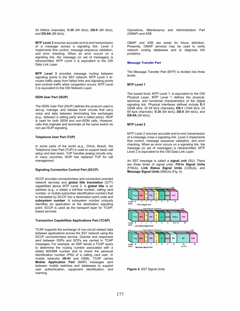
177
24 64kb/s channels), V.35 (64 kb/s), DS-0 (64 kb/s), and DS-0A (56 kb/s).
MTP Level 2 ensures accurate end-to-end transmission of a message across a signaling link. Level 2 implements flow control, message sequence validation, and error checking. When an error occurs on a signaling link, the message (or set of messages) is retransmitted. MTP Level 2 is equivalent to the OSI Data Link Layer.
MTP Level 3 provides message routing between signaling points in the SS7 network. MTP Level 3 re-routes traffic away from failed links and signaling points and controls traffic when congestion occurs. MTP Level 3 is equivalent to the OSI Network Layer.
ISDN User Part (ISUP)
The ISDN User Part (ISUP) defines the protocol used to set-up, manage, and release trunk circuits that carry voice and data between terminating line exchanges (e.g., between a calling party and a called party). ISUP is used for both ISDN and non-ISDN calls. However, calls that originate and terminate at the same switch do not use ISUP signaling.
Telephone User Part (TUP)
In some parts of the world (e.g., China, Brazil), the Telephone User Part (TUP) is used to support basic call setup and tear-down. TUP handles analog circuits only. In many countries, ISUP has replaced TUP for call management.
Signaling Connection Control Part (SCCP)
SCCP provides connectionless and connection-oriented network services and global title translation (GTT) capabilities above MTP Level 3. A global title is an address (e.g., a dialed a toll-free number, calling card number, or mobile subscriber identification number) that is translated by SCCP into a destination point code and subsystem number. A subsystem number uniquely identifies an application at the destination signaling point. SCCP is used as the transport layer for TCAP-based services.
Transaction Capabilities Applications Part (TCAP)
TCAP supports the exchange of non-circuit related data between applications across the SS7 network using the SCCP connectionless service. Queries and responses sent between SSPs and SCPs are carried in TCAP messages. For example, an SSP sends a TCAP query to determine the routing number associated with a dialed 800/888 number and to check the personal identification number (PIN) of a calling card user. In mobile networks (IS-41 and GSM), TCAP carries Mobile Application Part (MAP) messages sent between mobile switches and databases to support user authentication, equipment identification, and roaming.
Operations, Maintenance and Administration Part (OMAP) and ASE
OMAP and ASE are areas for future definition. Presently, OMAP services may be used to verify network routing databases and to diagnose link problems.
Message Transfer Part
The Message Transfer Part (MTP) is divided into three levels:
MTP Level 1
The lowest level, MTP Level 1, is equivalent to the OSI Physical Layer. MTP Level 1 defines the physical, electrical, and functional characteristics of the digital signaling link. Physical interfaces defined include E-1 (2048 kb/s; 32 64 kb/s channels), DS-1 (1544 kb/s; 24 64 kp/s channels), V.35 (64 kb/s), DS-0 (64 kb/s), and DS-0A (56 kb/s).
MTP Level 2
MTP Level 2 ensures accurate end-to-end transmission of a message cross a signaling link. Level 2 implements flow control, message sequence validation, and error checking. When an error occurs on a signaling link, the message (or set of messages) is retransmitted. MTP Level 2 is equivalent to the OSI Data Link Layer.
An SS7 message is called a signal unit (SU). There are three kinds of signal units: Fill-In Signal Units (FISUs), Link Status Signal Units (LSSUs), and Message Signal Units (MSUs) (Fig. 4).
Figure 4. SS7 Signal Units

178
Fill-In Signal Units (FISUs) are transmitted continuously on a signaling link in both directions unless other signal units (MSUs or LSSUs) are present. FISUs carry basic level 2 information only (e.g., acknowledgment of signal unit receipt by a remote signaling point). Because a CRC checksum is calculated for each FISU, both signaling points at either end of the link check signaling link quality continuously. (Note: In the ITU-T Japan variant, signaling link quality is checked by the continuous transmission of flag octets (8-bit bytes) rather than FISUs; FISUs are sent only at predefined timer intervals (e.g., once every 150 milliseconds).
Link Status Signal Units (LSSUs) carry one or two octets (8-bit bytes) of link status information between signaling points at either end of a link. The link status is used to control link alignment and to indicate the status of a signaling point (e.g., local processor outage) to the remote signaling point.
Message Signal Units (MSUs) carry all call control, database query and response, network management, and network maintenance data in the signaling information field (SIF). MSUs have a routing label which allows an originating signaling point to send information to a destination signaling point across the network.
The value of the LI (Length Indicator) field determines the signal unit type:
LI Value Signal Unit Type
0 Fill-In Signal Unit (FISU)
1..2 Link Status Signal Unit (LSSU)
3..63 Message Signal Unit (MSU)
Figure 5. Message Type Length Indicator Value(s)
The 6-bit LI can store values between zero and 63. If the number of octets which follow the LI and precede the CRC is less than 63, the LI contains this number. Otherwise, the LI is set to 63. An LI of 63 indicates that the message length is equal to or greater than 63 octets (up to a maximum of 273 octets). The maximum length of a signal unit is 279 octets: 273 octets (data) + 1 octet (flag) + 1 octet (BSN + BIB) + 1 octet (FSN + FIB) + 1 octet (LI + 2 bits spare) + 2 octets (CRC).
Flag The flag indicates the beginning of a new signal unit and implies the end of the previous signal unit (if any). The binary value of the flag is 0111 1110. Before transmitting a signal unit, MTP Level 2 removes "false flags" by adding a zero-bit after any sequence of five one-bits. Upon receiving a signal unit and stripping the flag, MTP Level 2 removes any zero-bit following a sequence of five one-bits to restore the original contents of the message. Duplicate flags are removed between signal units.
BSN (Backward Sequence Number) The BSN is used to acknowledge the receipt of signal units by the remote signaling point. The BSN contains the sequence number of the signal unit being acknowledged. (See description under FIB below.)
BIB (Backward Indicator Bit) The BIB indicates a negative acknowledgment by the remote signaling point when toggled. (See description under FIB below.)
FSN (Forward Sequence Number) The FSN contains the sequence number of the signal unit. (See description under FIB below.)
FIB (Forward Indicator Bit) The FIB is used in error recovery like the BIB. When a signal unit is ready for transmission, the signaling point increments the FSN (forward sequence number) by 1 (FSN = 0..127). The CRC (cyclic redundancy check) checksum value is calculated and appended to the forward message. Upon receiving the message, the remote signaling point checks the CRC and copies the value of the FSN into the BSN of the next available message scheduled for transmission back to the initiating signaling point. If the CRC is correct, the backward message is transmitted. If the CRC is incorrect, the remote signaling point indicates negative acknowledgment by toggling the BIB prior to sending the backward message. When the originating signaling point receives a negative acknowledgment, it retransmits all forward messages, beginning with the corrupted message, with the FIB toggled.
Because the 7-bit FSN can store values between zero and 127, a signaling point can send up to 128 signal units before requiring acknowledgment from the remote signaling point. The BSN indicates the last in-sequence signal unit received correctly by the remote signaling point. The BSN acknowledges all previously received signal units as well. For example, if a signaling point receives a signal unit with BSN = 5 followed by another with BSN = 10 (and the BIB is not toggled), the latter BSN implies successful receipt of signal units 6 through 9 as well.
SIO (Service Information Octet) The SIO field in an MSU contains the 4-bit subservice field followed by the 4-bit service indicator. FISUs and LSSUs do not contain an SIO.
The subservice field contains the network indicator (e.g., national or international) and the message priority (0..3 with 3 being the highest priority). Message priority is considered only under congestion conditions, not to control the order in which messages are transmitted. Low priority messages may be discarded during periods of congestion. Signaling link test messages receive a higher priority than call setup messages.
The service indicator specifies the MTP user (Fig. 6), thereby allowing the decoding of the information contained in the SIF.

179
Service Indicator MTP User
0 Signaling Network Management Message (SNM)
1 Maintenance Regular Message (MTN)
2 Maintenance Special Message (MTNS)
3 Signaling Connection Control Part (SCCP)
4 Telephone User Part (TUP)
5 ISDN User Part (ISUP)
6 Data User Part (call and circuit-related messages)
7 Data User Part (facility registration/cancellation messages)
Figure 6. Service Indicator Values
SIF (Signaling Information Field) The SIF in an MSU contains the routing label and signaling information (e.g., SCCP, TCAP, and ISUP message data). LSSUs and FISUs contain neither a routing label nor an SIO as they are sent between two directly connected signaling points. For more information about routing labels, refer to the description of MTP Level 3 below.
CRC (Cyclic Redundancy Check) The CRC value is used to detect and correct data transmission errors. For more information, see the description for BIB above.
MTP Level 3
MTP Level 3 provides message routing between signaling points in the SS7 network. MTP Level 3 is equivalent in function to the OSI Network Layer.
MTP Level 3 routes messages based on the routing label in the signaling information field (SIF) of message signal units. The routing label is comprised of the destination point code (DPC), originating point code (OPC), and signaling link selection (SLS) field. Points codes are numeric addresses which uniquely identify each signaling point in the SS7 network. When the destination point code in a message indicates the receiving signaling point, the message is distributed to the appropriate user part (e.g., ISUP or SCCP) indicated by the service indicator in the SIO. Messages destined for other signaling points are transferred provided that the receiving signaling point has message transfer capabilities (like an STP). The selection of outgoing link is based on information in the DPC and SLS.
An ANSI routing label uses 7 octets; an ITU-T routing label uses 4 octets (Fig. 7).
Figure 7. ANSI vs. ITU-T SIO and SIF
ANSI point codes use 24-bits (three octets); ITU-T point codes typically use 14-bits. For this reason, signaling information exchanged between ANSI and ITU-T networks must be routed through a gateway STP, protocol converter, or other signaling point that has both an ANSI and an ITU-T point code. (Note: China uses 24-bit ITU-T point codes that are incompatible with both ANSI and other ITU-T networks). Interaction between ANSI and ITU-T networks is further complicated by different implementations of higher level protocols and procedures.
An ANSI point code consists of network, cluster, and member octets (e.g., 245-16-0). An octet is an 8-bit byte that can contain any value between zero and 255. Telcos with large networks have unique network identifiers while smaller operators are assigned a unique cluster number within networks 1 through 4 (e.g., 1-123-9). Network number 0 is not used; network number 255 is reserved for future use.
ITU-T point codes are pure binary numbers that may be stated in terms of zone, area/network, and signaling point identification numbers. For example, the point code 5557 (decimal) may be stated as 2-182-5 (binary 010 10110110 101).
Signaling Link Selection (SLS) The selection of outgoing link is based on information in the DPC and Signaling Link Selection field. The SLS is used to:
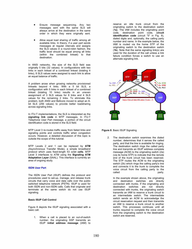
180
• Ensure message sequencing. Any two messages sent with the same SLS will always arrive at the destination in the same order in which they were originally sent.
• Allow equal load sharing of traffic among all available links. In theory, if a user part sends messages at regular intervals and assigns the SLS values in a round-robin fashion, the traffic level should be equal among all links (within the combined linkset) to that destination.
In ANSI networks, the size of the SLS field was originally 5 bits (32 values). In configurations with two links in each linkset of a combined linkset (totaling 4 links), 8 SLS values were assigned to each link to allow an equal balance of traffic.
A problem arose when growing networks provisioned linksets beyond 4 links. With a 5 bit SLS, a configuration with 5 links in each linkset of a combined linkset (totaling 10 links) results in an uneven assignment of 3 SLS values for 8 links and 4 SLS values for the remaining 2 links. To eliminate this problem, both ANSI and Bellcore moved to adopt an 8-bit SLS (256 values) to provide better loadsharing across signaling links.
In ITU-T implementations, the SLS is interpreted as the signaling link code in MTP messages. In ITU-T Telephone User Part message, a portion of the circuit identification code is stored in the SLS field.
MTP Level 3 re-routes traffic away from failed links and signaling points and controls traffic when congestion occurs. However, a detailed discussion of this topic is outside the scope of this tutorial.
MTP Levels 2 and 1 can be replaced by ATM (Asynchronous Transfer Mode), a simple broadband protocol which uses fixed-length 53 octet cells. MTP Level 3 interfaces to ATM using the Signaling ATM Adaptation Layer (SAAL). This interface is currently an area of ongoing study.
ISDN User Part
The ISDN User Part (ISUP) defines the protocol and procedures used to set-up, manage, and release trunk circuits that carry voice and data calls over the public switched telephone network (PSTN). ISUP is used for both ISDN and non-ISDN calls. Calls that originate and terminate at the same switch do not use ISUP signaling.
Basic ISUP Call Control
Figure 8 depicts the ISUP signaling associated with a basic call.
1. When a call is placed to an out-of-switch number, the originating SSP transmits an ISUP initial address message (IAM) to
reserve an idle trunk circuit from the originating switch to the destination switch (1a). The IAM includes the originating point code, destination point code, circuit identification code (circuit "5" in Fig. 8), dialed digits and, optionally, the calling party number and name. In the example below, the IAM is routed via the home STP of the originating switch to the destination switch (1b). Note that the same signaling link(s) are used for the duration of the call unless a link failure condition forces a switch to use an alternate signaling link.
Figure 8. Basic ISUP Signaling
2. The destination switch examines the dialed number, determines that it serves the called party, and that the line is available for ringing. The destination switch rings the called party line and transmits an ISUP address complete message (ACM) to the originating switch (2a) (via its home STP) to indicate that the remote end of the trunk circuit has been reserved. The STP routes the ACM to the originating switch (2b) which rings the calling party's line and connects it to the trunk to complete the voice circuit from the calling party to the called party. In the example shown above, the originating and destination switches are directly connected with trunks. If the originating and destination switches are not directly connected with trunks, the originating switch transmits an IAM to reserve a trunk circuit to an intermediate switch. The intermediate switch sends an ACM to acknowledge the circuit reservation request and then transmits an IAM to reserve a trunk circuit to another switch. This processes continues until all trunks required to complete the voice circuit from the originating switch to the destination switch are reserved.
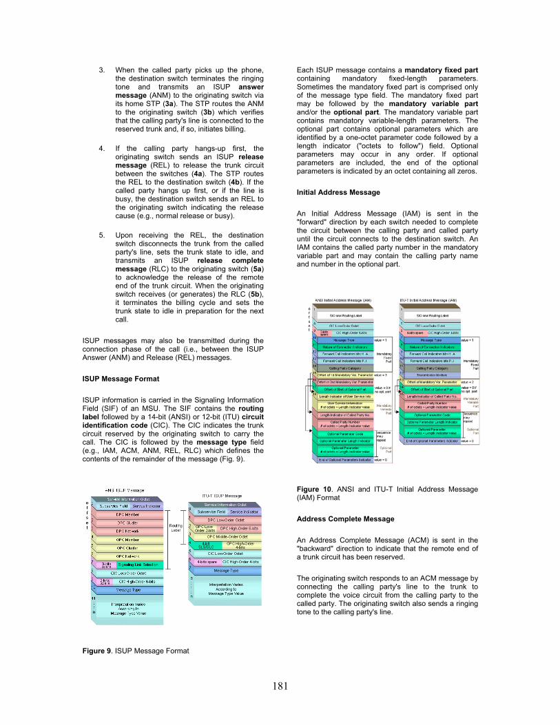
181
3. When the called party picks up the phone, the destination switch terminates the ringing tone and transmits an ISUP answer message (ANM) to the originating switch via its home STP (3a). The STP routes the ANM to the originating switch (3b) which verifies that the calling party's line is connected to the reserved trunk and, if so, initiates billing.
4. If the calling party hangs-up first, the originating switch sends an ISUP release message (REL) to release the trunk circuit between the switches (4a). The STP routes the REL to the destination switch (4b). If the called party hangs up first, or if the line is busy, the destination switch sends an REL to the originating switch indicating the release cause (e.g., normal release or busy).
5. Upon receiving the REL, the destination switch disconnects the trunk from the called party's line, sets the trunk state to idle, and transmits an ISUP release complete message (RLC) to the originating switch (5a) to acknowledge the release of the remote end of the trunk circuit. When the originating switch receives (or generates) the RLC (5b), it terminates the billing cycle and sets the trunk state to idle in preparation for the next call.
ISUP messages may also be transmitted during the connection phase of the call (i.e., between the ISUP Answer (ANM) and Release (REL) messages.
ISUP Message Format
ISUP information is carried in the Signaling Information Field (SIF) of an MSU. The SIF contains the routing label followed by a 14-bit (ANSI) or 12-bit (ITU) circuit identification code (CIC). The CIC indicates the trunk circuit reserved by the originating switch to carry the call. The CIC is followed by the message type field (e.g., IAM, ACM, ANM, REL, RLC) which defines the contents of the remainder of the message (Fig. 9).
Figure 9. ISUP Message Format
Each ISUP message contains a mandatory fixed part containing mandatory fixed-length parameters. Sometimes the mandatory fixed part is comprised only of the message type field. The mandatory fixed part may be followed by the mandatory variable part and/or the optional part. The mandatory variable part contains mandatory variable-length parameters. The optional part contains optional parameters which are identified by a one-octet parameter code followed by a length indicator ("octets to follow") field. Optional parameters may occur in any order. If optional parameters are included, the end of the optional parameters is indicated by an octet containing all zeros.
Initial Address Message
An Initial Address Message (IAM) is sent in the "forward" direction by each switch needed to complete the circuit between the calling party and called party until the circuit connects to the destination switch. An IAM contains the called party number in the mandatory variable part and may contain the calling party name and number in the optional part.
Figure 10. ANSI and ITU-T Initial Address Message (IAM) Format
Address Complete Message
An Address Complete Message (ACM) is sent in the "backward" direction to indicate that the remote end of a trunk circuit has been reserved.
The originating switch responds to an ACM message by connecting the calling party's line to the trunk to complete the voice circuit from the calling party to the called party. The originating switch also sends a ringing tone to the calling party's line.

182
Figure 11. ANSI and ITU-T Address Complete Message (ACM) Format
When the called party answers, the destination switch terminates the ringing tone and sends an Answer Message (ANM) to the originating switch. The originating switch initiates billing after verifying that the calling party's line is connected to the reserved trunk.
Figure 12. ANSI and ITU-T Answer Message (ANM) Format
Release Message
A Release Message (REL) is sent in either direction indicating that the circuit is being released due to the cause indicator specified. An REL is sent when either the calling or called party "hangs up" the call (cause = 16). An REL is also sent in the backward direction if the called party line is busy (cause = 17).
Figure 13. ANSI and ITU-T Release (REL) Message Format.
Release Complete Message
A Release Complete Message (RLC) is sent in the opposite direction of the REL to acknowledge the release of the remote end of a trunk circuit and end the billing cycle as appropriate.
Figure 14. ANSI and ITU-T Release Complete (RLC) Message Format
Telephone User Part
In some parts of the world (e.g., China), the Telephone User Part (TUP) supports basic call processing. TUP handles analog circuits only; the Data User Part provides digital circuits and data transmission capabilities.

183
Signaling Connection Control Part
SCCP provides connectionless and connection-oriented network services above MTP Level 3. While MTP Level 3 provides point codes to allow messages to be addressed to specific signaling points, SCCP provides subsystem numbers to allow messages to be addressed to specific applications (called subsystems) at these signaling points. SCCP is used as the transport layer for TCAP-based services such as freephone (800/888), calling card, local number portability, wireless roaming, and personal communications services (PCS). Global Title Translation
SCCP also provides the means by which an STP can perform global title translation (GTT), a procedure by which the destination signaling point and subsystem number (SSN) is determined from digits (i.e., the global title) present in the signaling message.
The global title digits may be any sequence of digits (e.g., the dialed 800/888 number, calling card number, or mobile subscriber identification number) pertinent to the service requested. Because an STP provides global title translation, originating signaling points do not need to know the destination point code or subsystem number of the associated service. Only the STPs need to maintain a database of destination point codes and subsystem numbers associated with specific services and possible destinations.
SCCP Message Format
The Service Indicator of the Service Information Octet (SIO) is coded 3 (binary 0011) for SCCP. SCCP messages are contained within the Signaling Information Field (SIF) of an MSU. The SIF contains the routing label followed by the SCCP message contents. The SCCP message is comprised of a one-octet message type field that defines the contents of the remainder of the message (Fig. 15).
Each SCCP message contains a mandatory fixed part (mandatory fixed-length parameters), mandatory variable part (mandatory variable-length parameters), and an optional part that may contain fixed-length and variable-length fields. Each optional part parameter is identified by a one-octet parameter code followed by a length indicator ("octets to follow") field. Optional parameters may occur in any order. If optional parameters are included, the end of the optional parameters is indicated by an octet containing all zeros.
Transaction Capabilities Application Part
TCAP enables the deployment of advanced intelligent network services by supporting non-circuit related information exchange between signaling points using the SCCP connectionless service. An SSP uses TCAP to query an SCP to determine the routing number(s) associated with a dialed 800, 888, or 900 number. The SCP uses TCAP to return a response containing the routing number(s) (or an error or reject component) back to the SSP. Calling card calls are also validated using TCAP query and response messages. When a mobile subscriber roams into a new mobile switching center (MSC) area, the integrated visitor location register requests service profile information from the subscriber's home location register (HLR) using mobile application part (MAP) information carried within TCAP messages.
TCAP messages are contained within the SCCP portion of an MSU. A TCAP message is comprised of a transaction portion and a component portion.
Transaction Portion
The transaction portion contains the package type identifier. There are seven package types:
• Unidirectional: Transfers component(s) in one direction only (no reply expected).
• Query with Permission: Initiates a TCAP transaction (e.g., a 1-800 query). The destination node may end the transaction.
• Query without Permission: Initiates a TCAP transaction. The destination node may not end the transaction.
• Response: Ends the TCAP transaction. A response to an 1-800 query with permission may contain the routing number(s) associated with the 800 number.
• Conversation with Permission: Continues a TCAP transaction. The destination node may end the transaction.
• Conversation without Permission: Continues a TCAP transaction. The destination node may not end the transaction.
• Abort: Terminates a transaction due to an abnormal situation.
The transaction portion also contains the Originating Transaction ID and Responding Transaction ID

184
fields that associate the TCAP transaction with a specific application at the originating and destination signaling points respectively.
Component Portion
The component portion contains components. There are six kinds of components:
• Invoke (Last): Invokes an operation. For example, a Query with Permission transaction may include an Invoke (Last) component to request SCP translation of a dialed 800 number. The component is the "last" component in the query.
• Invoke (Not Last): Similar to the Invoke (Last) component except that the component is followed by one or more components.
• Return Result (Last): Returns the result of an invoked operation. The component is the "last" component in the response.
• Return Result (Not Last): Similar to the Return Result (Last) component except that the component is followed by one or more components.
• Return Error: Reports the unsuccessful completion of an invoked operation.
• Reject: Indicates that an incorrect package type or component was received.
Components include parameters, which contain application-specific data carried unexamined by TCAP.
SS7 over IP
Telephone companies offload voice calls from public switched telephone networks (PSTNs) to voice-over-Internet Protocol (VoIP) networks because it is cheaper to carry voice traffic over Internet Protocol (IP) networks than over switched circuit networks. In the future, IP telephony networks are expected to enable innovative new multimedia services while working seamlessly with legacy telephone networks.
A VoIP network carries voice traffic cheaper than a switched circuit telephone network because IP telephony networks make better use of available bandwidth. In a public switched telephone network, for example, a dedicated 64 kilobits per second (kbps) end-to-end circuit is allocated for each call. In a VoIP network, digitized voice data is highly compressed and carried in packets over IP networks. Using the same bandwidth, a VoIP network can carry many times the number of voice calls as a switched circuit network with better voice quality. The savings realized in using VoIP networks are often passed onto users in the form of lower costs.
About the Company
Industrial Computer Group, Ltd. is a provider of networking solutions and equipment for seamlessly integrated data, voice and video communication services.
With a unified customer experience that goes beyond products and services, Industrial Computer Group provide customers with “end-to-end access solutions” by delivering world’s best innovative communications systems, products, technologies, and customer support.

185
The IPv6 Pilot Project at the Technical University of Cluj-Napoca
Kálmán Pusztai Otto Kreiter T. U. Cluj-Napoca, C.S. Dept. RoEduNet Cluj-Napoca [email protected] [email protected]
Marius Joldoş Zoltán Somodi T. U. Cluj-Napoca, C.S. Dept. T. U. Cluj-Napoca, C.S. Dept. [email protected] [email protected]
Abstract
This paper presents our pilot project for deploying native IPv6 in the MAN of the Technical University of Cluj-Napoca. It describes the problems and the solutions we have devised and implemented in this pilot project. The objectives of our project are to develop an understanding of the IPv6 networks and to gain experience in developing a dual-stack backbone, to operate a production IPv6 network and to encourage users to use IPv6. The pilot project uses Linux and BSD based routers, implementing stateless-autoconfiguration. We have also experienced DHCP6 for a more accurate address distribution and security in the network. This pilot project is the first phase in implementing and transition to native IPv6 in the Cluj-Napoca Academic MAN. Keywords: IPv6 protocol, network architecture, network security, network transition, Linux, BSD, MAN,DHCP6.
1. Introduction
Until recently, the Internet and most other TCP/IP networks have primarily provided support for rather simple distributed applications, such as file transfer, electronic mail, and remote access using TELNET; but today, the Internet is increasingly becoming a multimedia, application-rich environment, led by the huge popularity of the World Wide Web. At the same time, corporate networks have branched out from simple e-mail and file transfer applications to complex client/server environments and, most recently, intranets that mimic the applications available on the Internet. All of these developments have outstripped the capability of IP-based networks to supply needed functions and services. An internetworked environment needs to support real-time traffic,
flexible congestion control schemes, and security features. None of these requirements is easily met with the existing IP. With the changing nature of the Internet and business networks, the current Internet Protocol (IP), which is the backbone of Transmission Control Protocol (TCP)/IP networking, is rapidly becoming obsolete[1][2].
However, the driving force behind the development of a new IP is the stark fact that the world is running out of IP addresses for networked devices. The fixed 32-bit address length of IP is inadequate for the explosive growth of networks.
With the shortcomings of the existing IP becoming increasingly evident, a new protocol, known as IPv6 (IP version 6), has been defined to ultimately replace IP[3].
In response to these needs, the Internet Engineering Task Force (IETF) issued a call for proposals for a next-generation IP (IPng) in July of 1992. A number of proposals were received, and by 1994 the final design for IPng emerged. A major milestone was reached with the publication of RFC 1752, "The Recommendation for the IP Next Generation Protocol," issued in January 1995. RFC 1752 outlines the requirements for IPng, specifies the PDU formats, and highlights the IPng approach in the areas of addressing, routing, and security.
IPv6 has a number of new features designed to address the shortcomings of IPv4, including a new IP header format, a larger address space, a more efficient routing infrastructure, stateless and stateful address configurations, enhanced security, and standardized QoS support[4][5]. These features will be presented compared to IPv4.
The new header format. The first notable feature of the IPv6 protocol is a newly designed IP header. It's designed to make the protocol more efficient by keeping overhead to a minimum. An IP packet header is made up of required components and optional components; in IPv6, the required

186
components are moved to the front of the header. Optional components are moved to an extension header. This means that if optional components aren't used, the extension headers aren't necessary, reducing the packet size. The simplified header reduce the processing time that makes routing process faster.
The downside to the new header is that it isn’t compatible with IPv4. If a router is to handle both IPv4 and IPv6, it must be configured to recognize both protocols. You can’t just set up a router to recognize IPv6 and expect it to be backward-compatible with IPv4.
Larger address space. Perhaps the most compelling reason for moving to IPv6 is the current shortage of IP addresses. IPv6 uses 128-bit source and destination addresses. There are theoretically over 3.4x10^38 possible addresses that can be addressed by the IPv6 protocol. Furthermore, this new structure allows for more levels of subnetting than are available with IPv4. Some people speculate that because of the large number of addresses that IPv6 allows, NAT technology may soon become a thing of the past.
More efficient routing. The Internet is hierarchical in nature, and the IPv6 protocol is designed with this in mind. Internet backbone routers will have much smaller routing tables than they have now. Instead of knowing every possible route, the routing tables will include routes to only those routers connected directly to them. The IPv6 protocol will contain the rest of the information necessary for a packet to reach its destination. By this means the number of entries in backbone routers will be reduced from more then 50.000 to 8192.
New configuration options. One of the most important advantage of IPv6 is the way it's configured. While you can still manually configure IPv6, or lease an address from a DHCP server, there is a new automatic configuration option available. If an unconfigured PC tries to connect to a network that doesn’t offer a DHCP server, the PC can look at either the network’s router or the other PCs on the network and determine an address that would be appropriate for it to use. This technique is referred to as link local addressing.
Integrated security. IPSec is available in some implementations of IPv4, but it’s completely integrated into IPv6. Any computer that’s running IPv6 will support IPSec encryption, regardless of the computer’s operating system.
Standardized QoS support. IPv6 also includes standardized support for QoS. The QoS implementation is set up so that routers can identify packets belonging to an individual QoS flow. This allows those routers to allocate the necessary amount of bandwidth to those packets. Furthermore, QoS instructions are included in the IPv6 packet header. This means that the packet body can be encrypted, but QoS will still function because the header portion containing the QoS instructions is not
encrypted. This will make it possible to send streaming audio and video over the Internet with IPSec encryption, but in a manner that guarantees adequate bandwidth for real-time playback.
In addition to solving the addressing problem there are several reason for going forward with IPv6: Quality of Service features, larger MTU, routing improvements, security features, support for mobility, autoconfiguration enhancements, and much more.
2. IPv4 to IPv6 transition
IPv6 and IPv4 are two different protocols that need to co-exist for an unknown amount of time[6]. This is due to the need to give time to the entire Internet's population to make the switch from the older IPv4 to the new IPv6. The protocols are so different that some techniques must be used to allow them to work together while the various networks on the Internet are in flux between the two. There is expected to be a long transition period during which it will be necessary for IPv4 and IPv6 nodes to coexist and communicate. A strong, flexible set of IPv4-IPv6 transition and coexistence mechanisms will be required during this transition period.
The IPv6 protocol is designed for a long coexistence with the old protocol without any problem. There is no fixed day when all networks from the Internet have to finished the transition process. Due to transition mechanisms no network stand-down required during the transition.
So we have enough time and we need as much time as possible for transition. But delaying start of transition compresses the transition period, i.e. for the same amount of work we will have less time to do it. Accordingly the transition has to be started as early as possible.
There are two more aspects related to time: 1. Transition must be mostly complete before
runout 2. All nodes requiring global connectivity should
be converted to IPv6 before run-out to avoid discontinuity
From the users' point of view, who come in contact with the Internet through their web browser or email client, the transition has to be transparent and unobservable. The users do not meet with the 128 bit addresses because the applications (www, smtp, imap, pop3, telnet, ftp) use symbolic names rather then IP addresses. A 128 bit address should appear in the header of the email, but a normal user has no concern to it. The port number for some URL may differ from the port used in IPv4, but usually the port is included in the hypertext link.
From the network administrators point of view, the transition requires the following tasks:
1. Elaborating the transition strategy 2. Choosing a transition method 3. Elaborating the transition mechanism 4. Implementing the transition mechanism 5. Evaluating the transition

187
These steps should be executed several times depending on the change of requirements. The appropriate transition mechanism depends on the environment in which the network operates.
2.1. Transition mechanisms
IPv6 and IPv4 will coexist for many years. A wide range of techniques has therefore been defined that make the coexistence possible and provide an easy transition. There are three main categories[7]:
1. Dual-stack techniques allow IPv4 and IPv6 to coexist in the same devices and networks.
2. Tunneling techniques allow the transport of IPv6 traffic over the existing IPv4 infrastructure.
3. Translation techniques allow IPv6-only nodes to communicate with IPv4-only nodes.
These techniques can and likely will be used in combination with one another. The migration to IPv6 can be done step by step, starting with a single host or subnet. One can migrate its corporate network, or parts of it, while its ISP still runs only IPv4. Or the IPS can upgrade to IPv6 while the corporate network still runs IPv4. This chapter describes the techniques available today for each category mentioned above. RFC 2893, “Transition Mechanisms for IPv6 Hosts and Routers”, describes the initial set of transition mechanisms. As IPv6 grows into our networks, new tools and mechanisms will be defined to further ease the transition.
Dual-Stack Techniques. Dual stack backbone is a basic strategy for routing both IPv4 and IPv6 and requires network devices such as routers and end systems running both IPv4 and IPv6 protocol stacks. Dual stack end systems allow applications to migrate one at a time from an IPv4 to an IPv6 transport. Applications that are not upgraded to support IPv6 stack can coexist with upgraded applications on the same end system.
Figure 2. Dual stack hierarchy
As shown in Figure 2, new and upgraded applications simply make use of both the IPv4 and IPv6 protocol stacks. A new application-
programming interface (API) has been defined to support both IPv4 and IPv6 addresses and DNS requests. An application can be upgraded to the new API and still use only the IPv4 protocol stack.
Applications choose between using IPv4 or IPv6 protocol based on name lookup; both the IPv4 and IPv6 addresses may be returned from the DNS, with the application (or the system according to the rules defined in the IETF document Default Address Selection for IPv6) selecting the correct address based on the type of IP traffic and particular requirements of the communication.
An application that supports dual IPv4 and IPv6 protocol stacks requests all available addresses for the destination host name (for example, www.a.com) from a DNS server. The DNS server replies with all available addresses (both IPv4 and IPv6 addresses) for www.a.com. The application chooses an address – in most cases, IPv6 addresses are the default choice – and connects the source node to the destination using the IPv6 protocol stack.
Today, dual-stack routing is a valid deployment strategy for specific network infrastructures with a mixture of IPv4 and IPv6 applications (such as on a campus or an aggregation point of presence), requiring both protocols to be configured. However, apart from the obvious need to upgrade all routers in the network, limitations to this approach are that the routers require a dual addressing scheme to be defined, require dual management of the IPv4 and IPv6 routing protocols, and must be configured with enough memory for both the IPv4 and IPv6 routing tables.
Tunneling Techniques. Tunneling encapsulates IPv6 traffic within IPv4 packets so they can be sent over an IPv4 backbone, allowing isolated IPv6 end systems and routers to communicate without the need to upgrade the IPv4 infrastructure that exists between them. Tunneling is one of the key deployment strategies for both service providers and enterprises during the period of IPv4 and IPv6 coexistence.
Tunneling allows service providers to offer an end-to-end IPv6 service without major upgrades to the infrastructure and without impacting current IPv4 services and allows enterprises to interconnect isolated IPv6 domains over their existing IPv4 infrastructures, or to connect to remote IPv6 networks such as the 6bone.
The tunneling techniques and the encapsulation of IPv6 packets in IPv4 packets are defined in several RFCs, which differentiate two types of tunneling:
1. Manually configured tunneling of IPv6 over IPv4: IPv6 packets are encapsulated in IPv4 packets to be carried over IPv4 routing infrastructures. These are point-to-point tunnels that need to be configured manually.
2. Automatic tunneling of IPv6 over IPv4: IPv6 nodes can use different types of addresses, such as IPv4-compatible IPv6 addresses or

188
6to4 or ISATAP addresses, to dynamically tunnel IPv6 packets over an IPv4 routing infrastructure. These special IPv6 unicast addresses carry an IPv4 address in some of the IPv6 address fields.
All tunneling mechanisms require that the endpoints of the tunnel run both IPv4 and IPv6 protocol stacks, that is, endpoints must run in dual-stack mode. The dual-stack routers run both IPv4 and IPv6 protocols simultaneously and thus can interoperate directly with both IPv4 and IPv6 end systems and routers.
Configured tunneling [8] is a manually configured tunnel.. The primary use of a configured tunnel is to provide stable and secure connections for regular communication between two edge routers, or between an end system and an edge router, or for connection to remote IPv6 networks such as the 6bone. The edge routers and end systems used as tunnel endpoints must be dual-stack devices. Manual tunnels are used between two points and require configuration of both the source and destination addresses of the tunnel, whereas automatic tunnel mechanisms need to be only enabled and are more transient.
Because each tunnel is independently managed, the more tunnel endpoints you have, the more tunnels you need, and the greater is the management overhead. As with other tunnel mechanisms, network address translation (NAT) is not allowed along the path of the tunnel.
IPv6 over IPv4 GRE Tunnel is an automatic tunneling technique. The IPv6 over IPv4 GRE tunnel uses the standard GRE tunneling technique that is designed to provide the services necessary to implement any standard point-to-point encapsulation scheme. As in manually configured tunnels, these tunnels are links between two points, with a separate tunnel for each link. The GRE tunnels are not tied to a specific passenger or transport protocol, but in this case carry IPv6 traffic as the passenger protocol over GRE as the carrier protocol.
Similar to the manual tunnels, the GRE tunnels are used between two points and require configuration of both the source and destination addresses of the tunnel. The edge routers and end systems used as tunnel end points must be dual stack devices.
Because the integrated IS-IS routing protocol runs over a Layer 2 data link, tunneling techniques other than GRE cannot be used. The IPv6 over IPv4 GRE tunnel uses the standard GRE tunneling technique that is designed to provide the services necessary to implement any standard point-to-point encapsulation scheme.
As with manually configured tunnels, you configure the IPv4 and IPv6 addresses of the dual-stack router on the GRE tunnel interface, and identify the entry and exit (or source and destination) points of the tunnel, using IPv4 addresses.
Because each GRE tunnel is independently
managed, the more tunnel endpoints you have, the more tunnels you need, and the greater is the management overhead. As with other tunnel mechanisms, network address translation (NAT) is not allowed along the path of the tunnel.
Automatic IPv4-Compatible Tunnel. The automatic IPv4-compatible tunnel is an IPv6 over IPv4 tunnel mechanism, which uses an IPv4-compatible IPv6 address. An IPv4-compatible IPv6 address is the concatenation of zeros in the left-most 96 bits and an IPv4 address embedded in the last 32 bits. For example, ::192.168.99.1 is an IPv4-compatible IPv6 address.
Although an automatic tunnel can be configured between end systems, edge routers, or an edge router and an end system, the automatic IPv4-compatible tunnel has mainly been used to establish connection between routers.
Unlike a manually configured tunnel, the automatic IPv4-compatible tunnel technique constructs tunnels with remote nodes on the fly. Manual configuration of the endpoints of the tunnel is not required because the tunnel source and the tunnel destination are automatically determined by the IPv4 address. The automatic tunnels are set up and taken down as required, and last only as long as the communication.
Although an easy way to create tunnels, the IPv4-compatible tunnel mechanism does not scale well for IPv6 networks deployment, because each host requires an IPv4 address removing the benefit of the large IPv6 addressing space. The IPv4-compatible tunnel is largely replaced by the 6to4 automatic tunnel mechanism. Hence, the use of IPv4-compatible tunnel as a transition mechanism is nearly deprecated.
Automatic 6to4 Tunnel [9]. An automatic 6to4 tunnel allows isolated IPv6 domains to be connected over an IPv4 network and allows connections to remote IPv6 networks, such as the 6bone.
The simplest deployment scenario for 6to4 tunnels is to interconnect multiple IPv6 sites, each of which has at least one connection to a shared IPv4 network. This IPv4 network could be the global Internet or could be a corporate backbone. The 6to4 tunnel treats the IPv4 infrastructure as a virtual nonbroadcast link using an IPv4 address embedded in the IPv6 address to find the other end of the tunnel. Each IPv6 domain requires a dual-stack router that automatically builds the IPv4 tunnel using a unique routing prefix 2002::/16 in the IPv6 address with the IPv4 address of the tunnel destination concatenated to the unique routing prefix. The key requirement is that each site has a 6to4 IPv6 address. Each site, even if it has just one public IPv4 address, has a unique routing prefix in IPv6.
All sites need to run an IPv6 interior routing protocol, such as routing information protocol next generation (RIPng) for routing IPv6 within the site; exterior routing is handled by the relevant IPv4 exterior routing protocol.
189
ISATAP Tunnel is another automatic tunneling technique . ISATAP is an IPv6 transition mechanism similar to 6to4 tunnels that enables incremental deployment of IPv6 by treating the site IPv4 infrastructure as a nonbroadcast multiaccess (NBMA) link layer.
The ISATAP transition mechanism enables a simple and scalable large-scale incremental deployment of IPv6 for nodes within the existing IPv4 network of a site without incurring aggregation-scaling issues and without the requirement for site-wide deployment of special IPv4 services such as multicast.
ISATAP tunnels are available for use over campus networks or for the transition of local sites. ISATAP supports IPv6 routing within both the site-local and global IPv6 routing domains and automatic IPv6 tunneling across portions of an IPv4 network of a site without any native IPv6 support. ISATAP also supports automatic tunneling within sites that use nonglobally unique IPv4 address assignments combined with network address translation (NAT). All ISATAP nodes are dual stacked.
ISATAP uses a 64-bit network prefix from which the ISATAP addresses are formed. The 64-bit interface identifier is formed by concatenating 0000:5EFE and the IPv4 address of the dual-stack node (192.168.99.1). For example, 3FFE:0B00:0C18:0001:0:5EFE.192.168.99.1 is an ISATAP address. Because ISATAP tunneling typically occurs only within the boundaries of a site, the embedded IPv4 address need not be globally unique.
Teredo Tunnel is an automatic tunnel. The Teredo (also known as Shipworm) service is a tunnel mechanism that provides IPv6 connectivity to nodes located behind one or more IPv4 NATs by tunneling IPv6 packets over the User Datagram Protocol (UDP) through NAT devices. The Teredo service is defined for the case where the NAT device cannot be upgraded to offer native IPv6 routing or act as a 6to4 router.
Teredo tunnels use Teredo servers and Teredo relays. The Teredo servers are stateless, and manage a small fraction of the traffic between Teredo clients, while the Teredo relays act as IPv6 routers between the Teredo service and the native IPv6 Internet. The Teredo network consists of a set of Teredo clients, servers, and relays. The Teredo network does not require configuration for the Teredo clients. The clients are assigned specially formed IPv6 address prefix, and Teredo servers and relays use globally unique IPv4 addresses.
Translation Techniques. All of these integration strategies provide IPv6 end to end. However, some organizations or individuals might not want to implement any of these IPv6 transition strategies. And some organizations or individuals might install only IPv6 in their nodes or networks, but might not implement dual stack. Even if some nodes or networks do install dual stack, these nodes might not have IPv4 addresses to be used with the
dual-stack nodes. Under these circumstances, intercommunication
between IPv6-only hosts and IPv4-only hosts requires some level of translation between the IPv6 and IPv4 protocols on the host or router, or dual-stack hosts, with an application-level understanding of which protocol to use. For example, an IPv6-only network might still want to be able to access IPv4-only resources, such as IPv4-only web servers.
A variety of IPv6-to-IPv4 translation mechanisms are under consideration by the IETF NGTrans Working Group, as follows:
1. Network Address Translation (NAT): Translates IP address, IP, TCP, UDP and ICMP header checksums.
2. Network Address Port Translation (NAPT): In addition to the fields translated by NAT transport, identifiers such as TCP and UPD port numbers and ICMP message types are translated.
3. Network Address Translation and Protocol Translation (NAT-PT): Translates an IPv6 packet into an equivalent IPv4 packet and vice versa.
4. Network Address Port Translation and Protocol Translation (NAPT-PT): Allows IPv6 hosts to communicate with IPv4 hosts using a single IPv4 address.
The disadvantages of this techniques are that it does not support the advanced features of IPv6, such as end-to-end security. It poses limitations on the design topology because replies have to come through the same NAT router from which they were sent. The NAT router is a single point of failure, and flexible routing mechanisms cannot be used. All applications that have IP addresses in the payload of the packets will stumble.
Vendor Support. The number of vendors who support IPv6 is growing daily. Since in our institution Microsoft Windows and Linux operating systems and Cisco routers are used, these vendors' products will be presented shortly in the next sections.
IPv6 Support from Cisco. Cisco Systems is one of the founding members of the IPv6 Forum[10]. Cisco has taken a leading role in the definition and implementation of the IPv6 architecture within the IETF and continues to lead the industry efforts for standardization.
IPv6 for Cisco IOS Software is available for all Cisco router platforms, from the low-end Cisco 800 series routers to high-end platforms that include the Cisco 12000 Internet routers. Since Cisco IOS Software Release 12.2(2)T, Cisco officially provides worldwide technical support.
IPv6 in Microsoft Windows. Microsoft Research (MSR) has been contributing to the standardization effort since 1996. To further networking research on the Windows NT/2000 platform, Microsoft elected to write an IPv6 implementation and make it available to the public in both source and binary forms. Today every copy of Windows XP contains

190
an IPv6 stack thanks to this research. MSR continues to be active in IPv6-related research, particularly in the mobile arena.
MSRIPv6 was the first version of Microsoft's IPv6 implementation, released in 1998. Early in 2000, Microsoft began helping the Windows Networking product group in their effort to produce a production version of IPv6 for future versions of Microsoft Windows. The preliminary results of this project became available as a Technology Preview for Windows 2000 SP1[11]. It is also suitable for Windows 2000 SP2 and SP3. In October 2001, the Windows XP was released, every copy of which has a built-in IPv6 stack.
Windows .NET Server include the first fully-supported release of the Microsoft IPv6 stack. This stack has been designed for full production use, suitable for live commercial deployments.
An ever-increasing number of Windows applications have been ported to run over IPv6: ping6, tracert6, and ttcp, Internet Explorer, Telnet and FTP clients, Applications that communicate via RPC and a large number of third-party applications. 6To4 and ISATAP is also supported by Windows XP[12].
Linux and Ipv6. The first IPv6 related network code was added to the Linux kernel 2.1.8 in November 1996 by Pedro Roque[13]. In October 2000, a project was started in Japan, called USAGI, whose aim was to implement all missing, or outdated IPv6 support in Linux. It tracks the current IPv6 implementation in FreeBSD made by the KAME project. From time to time they create snapshots against current vanilla Linux kernel sources.
Unfortunately, the USAGI patch is so big, that current Linux networking maintainers are unable to include it in the production source of the Linux kernel 2.4.x series. Therefore the 2.4.x series is missing some (many) extensions and also does not confirm to all current drafts and RFCs. This can cause some interoperability problems with other operating systems. USAGI is now making use of the new Linux kernel development series 2.5.x to insert all of their current extensions into this development release. Hopefully the 2.6.x kernel series will contain a true and up-to-date IPv6 implementation.
In the 2.4 kernel the IPv6 protocol stack is automatically enabled in addition to the IPv4 stack. The current inet daemon supports IPv6 and is responsible for all networking tasks, such as FTP, telnet or finger. The configuration file /etc/inted.conf must be changed for IPv6 support.
There are two packages that include utilities for IPv6. One of them is net-tools. This package contains the source code for utilities such as ifconfig, netstat, route and hostname. The another package is iputils which contains ping6, tracepath6 and traceroute6.
Linux supports almost all upper-layer protocols, such as DNS (IPv6 address records and IPv6 transport), HTTP, SMTP, DHCP, SLP, IMAP,
POP3 etc. Using a special application (e.g zebra) a Linux-based machine can be transformed into an IPv6 router. There exists also IPv6 based web servers.
Currently, Linux offers a much larger support for IPv6 then Microsoft Windows operating system.
2.2. The costs of transition
The transition will be relatively easy and its cost will be low due to the high level of development of transition mechanisms. The transition properties of IPv6 considering the network management aspects are listed below:
1. A conceptually new system, which conserve the good concepts from Ipv4.
2. The Internet moves in this direction. How does not apply, will not be able to communicate.
3. The users will not experience too many things from transition, if it was made correctly.
4. The transition do not have a fixed day and do not imply the stand-down of the entire network.
5. There is an immediate advantage that the efficiency will increase due to the new features of IPv6 (autoconfiguration, more efficient routing, security, etc).
6. The transition to IPv6 is not avoidable. The main question is when to start the transition? The cost of transition has different
components: acquisition, education, management, translation of locally implemented applications.
The acquisition plan has to determine the new devices, softwares and updates required. These new devices can be bought when a general upgrade is made in the system. Thus the transition does not imply high additional costs. Today, the most important hardware and software manufacturers offer IPv6 compatible products (Compaq, IBM, Microsoft, Sun, FreeBSD, OpenBSD, Linux, Cisco,Nortel, Ericsson, Hitachi).
The estimation of the costs of network administration is not easy. The cost will depend on the following aspects: management of addressing and routing, management of transition mechanisms, security management, network supervising.
The cost of the education depends on the available source of information. Different seminars and conferences are organized world-wide. The manufactures are also interested in presentation of their IPv6 compatible products. An important role in fall on the universities to introduce students in the newest technology.
The problem of translation of locally implemented applications resembles the 2000 year problem. There are two main possible approaches:
1. Implementation of a translation method which does not make necessary the modification of the applications.
2. Automatic and semiautomatic translators and

191
tools for modifying the applications.
3. Worldwide initiatives
Almost all operating system and router manufacturers have been developed their IPv6 implementations. There are around 50 different implementations including the implementations for FreeBSD, NetBSD, Linux, Solaris, AIX, Tru64 Unix, HP-UX, SCO, IRIX, Windows 9X, Windows NT, Windows 2000, Windows XP, Open VMS, UnixWare, OS/390, MacOS operating systems and the implementations for the most important router manufacturers' devices: Cisco, Nortel, Juniper, 3Com, Hitachi, Ericsson, Nokia, Telebit, etc. The 3rd generation mobile devices also support the new IP protocol. Thus more and more system operates word-wide which could transit in any moment to IPv6.
The allocation of the 128 bit addresses is in progress and the number of applications that are able to communicate over IPv6 increase.
The most important international testbed of IPv6 is the 6bone network. This is an experimental IPv6 network which has both native and tunneled IPv6 links. There are a number of national experimental IPv6 networks. The most important are the American, Canadian and Japanese networks. There are many international research projects in this domain: 6ren, 6tap, freenet6, Quantum IPv6.
There are already a surprising number of global test networks and even commercial networks running over IPv6. In April 2003 over 125 production networks have been allocated IPv6 address prefixes[14]. In the next sections some interesting examples will be discussed.
3.1. The 6bone network
The 6bone is an experimental IPv6 network
layered on top of portions of the physical IPv4-based Internet to support routing of IPv6 packets within an environment where this function is not yet integrated into the production routers. The network is made up of islands that can directly support IPv6 packets, linked mainly by virtual point-to-point links called "tunnels"[15].
The idea to set up an experimental IPv6 backbone over the Internet was the result of a spontaneous initiative of several research institutes involved in the experimentation of the first implementations of the IPv6 protocol. The network became a reality in march 1996 with the establishment of the first tunnels between the IPv6 laboratories of G6 (France), UNI-C (Denmark) and WIDE (Japan).
The 6bone is the place where the most interesting geographical experimentation on the IPv6 protocol is currently taking place. The experimental activities carried out inside the 6bone are co-ordinated by the IETF in order to provide feedback to various IETF IPv6-related activities and to IPv6 product developers based on testbed experience.
The 6bone is structured as a three levels hierarchical network with backbone nodes, transit nodes and leaf nodes. The 6bone backbone is made of a mesh of IPv6 over IPv4 tunnels (and some direct links) interconnecting backbone nodes only. IPv6 routing inside the backbone is based on the BGP4+ protocol. Transit nodes connect to one or more backbone nodes and provide transit service for leaf sites. Routing outside the backbone is mainly static but the number of non-backbone sites making use of IPv6 routing protocols such as RIPng and BGP4+ is rapidly growing.
IPv6 addressing inside the 6bone is based on the new IPv6 Aggregatable Global Unicast Address Format and it matches the hierarchical topology
1. Figure 1. 6bone sites by country (Source: 6bone Registry).
192
described above. Backbone nodes play the role of experimental Top Level Aggregators (pTLAs, pseudo Top Level Aggregators) and they are responsible for assigning IPv6 addresses to non-backbone sites in such a way to establish an addressing hierarchy capable to enforce aggregation of routing information.
The whole 6bone is identified by the IPv6 prefix 3ffe::/16 and every backbone node is assigned a 24 or 28 bit long prefix (pTLA prefix) identifying an IPv6 addressing space which must be administered following all the rules defined for the TLAs. According to this model every pTLA plays the role of experimental top level ISP and has to assign chunks of its addressing space to directly connected transit and leaf sites without breaking aggregation inside the 6bone backbone.
Since its creation in 1996 the 6bone has been steadily growing in the number of connected sites. In July 1997 the network encompassed about 150 sites; in January 2000 more than 500 sites distributed in 42 countries all over the world were officially registered in the 6bone registry database. Over the same period of time the number of 6bone backbone sites (i.e. assigned pTLAs) has increased from 36 to 67. Nowdays, the number of nodes is over 1000 nodes and grows daily. At end of April, 2003 the total number of connected 6bone sites was 1329 distributed in 60 countries [16].
3.2. National IPv6 networks
Internet2 (USA). Internet2 is a consortium being led by 202 universities working in partnership with industry and government to develop and deploy advanced network applications and technologies, accelerating the creation of tomorrow's Internet. Internet2 is recreating the partnership among academia, industry and government that fostered today's Internet in its infancy. The primary goals of Internet2 are to create a leading edge network capability for the national research community, to enable revolutionary Internet applications and to ensure the rapid transfer of new network services and applications to the broader Internet community.
Development activities of Internet2 are performed in committees known as Working Groups (WG). The IPv6 WG is focused both on understanding how IPv6 will enable Internet2 to achieve its goals and on promoting and coordinating the deployment of IPv6 throughout the Internet2 infrastructure [17].
Abilene is an advanced backbone network that connects regional network aggregation points, to support the work of Internet2 universities as they develop advanced Internet applications. The Abilene Network is partnership of Internet2, Qwest Communications, Cisco Systems, Nortel Networks, Juniper Networks, and Indiana University. The network is undergoing an upgrade from 2.5 Gigabits/sec to 10 Gigabits/sec expected to be completed by the end of 2003. The Abilene IPv6
backbone currently consists of four Cisco 7200 routers connected by a full mesh of IPv6-in-IPv4 tunnels. The underlying Abilene IPv4 network is used for transport. The four routers are co-located at GigaPoPs.
There are 4 IPv6 POP nodes at San Diego, San Francisco, Chicago and Perryman and the backbone is connected to vBNS, 6TAP, StarTAP, NGSIX and APAN over IPv6.
CA*net2 and CA*net3 projects (Canada). The main objective of CA*net 2, an initiative of the CANARIE (Canadian Network for the Advancement of Research, Industry and Education), was the replacement Research and Development national backbone network[18]. It was based on the ATM (Asynchronous Transfer Mode) and SONET facilities operated by Canada's Telecommunications carriers. Average speeds were to be 155 Mbps, the fastest and largest national network in the world (at start-up time). CA*net 2 is connected in each province to Regional Advanced Networks (some provinces have more than one connection to their RAN), via GigaPoPs (Gigabit Point of Presence).
6POP.CA. The 6POP.CA project was designed to ease the transition to IPv6 for the Canadian R&E community and, by extension, the commercial networking community. It was planned to do this by implementing IPv6 across CA*net2, by participating in international development and deployment efforts, and by making our experience available to the commercial backbone networks.
The main goals of the 6POP.CA project was: 1. To develop plans for a transition of CA*net2
from a pure IPv4 network to a hybrid - and eventually a native - IPv6 network.
2. To establish an IPv6 backbone (6bone) tunnel across the CA*net2 backbone connected to similar backbones in other countries. This tunnel would form the basis of an eventual migration to IPv6, and would provide training and experience in the meantime.
3. To contribute to the development of IPv6 network tools for the community.
4. As part of the development effort, to participate in the IPNG IETF working group and to contribute to the appropriate RFCs and Internet Drafts as necessary.
5. To establish and maintain a web site and an e-mail list for use by Canadians and others interested in this project. The web site will be used, for example, to distribute information about 6bone connections, recommended configurations, and project highlights.
6. To develop the outline for an address registry for Canada.
IPv6 is moving from an experimental to a production protocol. As part of this transition the worldwide topology is changing from arbitrary v6-over-v4 tunnels to production quality native v6 links. A major exchange point for these links in North America, called the 6TAP, is at the StarTap in

193
Chicago. CANARIE and ESnet are jointly sponsoring networking equipment and configurations that serve as the hub of all IPv6 exchange traffic for the world's advanced networks.
In collaboration with CANARIE Viagénie has been working on different IPv6-related projects. They contribute to set up IPv6-supported services and applications to be widely used by people, modified the Quake game code to be used on IPv6. The Viagénie team developed the Freenet6 software package, to get free IPv6 connectivity and a link toward the 6bone, conceived a system that facilitates IPv6 address assignment and connectivity via IPv4 for any Internet connected system. Also they deployed the IPv6 Canadian network on Canarie's, the 6bone. A testbed was also set up on the IP network. This would allow an evaluation of IPv6 implementation under routers and platform. environment.
WIDE backbone project (Japan). The aim of the WIDE Project, launched in 1988, is to establish a Widely Integrated Distributed Environment: a new computer environment based on operating systems and communications technology, designed to benefit the human race on a broad scale[19].
Fifteen years after the born of WIDE, IPv6, the next-generation Internet protocol, is in actual use, and automobiles, household appliances and all sorts of other products are becoming available in Internet-capable form. The experimental environment created by the WIDE Project is the WIDE Internet, which was also the first incarnation of the Internet in Japan.
A WIDE started the Wide v6 Working Group in 1995 for the purpose of the deployment of the IPv6 environment [20]. In the late of 1995, v6 WG had several independent implementations and held interoperability test events. Although WIDE v6 WG started later than other research institutes, some activities were the first of the world. An example is carrying IPv6 packets on leased lines.
WIDE started three important subproject for different IPv6 developments: KAME Project, TAHI project and USAGI project. As the specification was verified and interoperability became common, it appeared ineffective for IPv6 WG to implement IPv6 stacks independently. So, the WIDE started KAME project as a subproject for the purpose of combining the power of implementation. Although the members of IPv6 WG and KAME overlap, while IPv6 WG does technical and innovative researches mainly, KAME is in charge of implementation.
The KAME Project is a joint effort of six companies in Japan (Fujitsu, Hitachi, Internet Initiative Japan, NEC, Toshiba, Yokogawa Electric Corporation) to provide a free IPv6 and IPsec (for both IPv4 and IPv6) stack for BSD variants to the world[21]. KAME project was started as a 2-year project (April 1998 - March 2000). It has got extension for 2 years TWICE, so will be until March 2004 at this moment.
The TAHI Project is the joint effort formed
with the objective of developing and providing the verification technology for IPv6[22].
The growth process of IPv4 was the history of encountering various kinds of obstacles and conquering such obstacles. However, once the position as infrastructure was established, it is not allowed to repeat the same history. This is a reason why the verification technology is essential for IPv6 deployment.
The project started at October 1, 1998, and formed by The University of Tokyo and the Yokogawa Electric Corp., has the followings main targets:
1. Research and develop conformance tests and interoperability tests for IPv6.
2. Closely collaborate with KAME Project and USAGI Project; help activities of the them in the quality side by offering the verification technology developed in the TAHI project and improve the development efficiency.
3. Open the results and fruits of the project to the public for FREE. Any developer concerned with IPv6 can utilize the results and fruits of TAHI project freely. Besides the programs, the specifications and criteria of verification will be included in the Package.
The USAGI (UniverSAl playGround for IPv6) Project is a aggressive IPv6 development project, mainly for Linux systems. It works to deliver the production quality IPv6 and IPsec(for both IPv4 and IPv6) protocol stack for the Linux system, tightly collaborating with WIDE Project, KAME Project and TAHI Project[23]. USAGI Project is run by volunteers from various organizations, at this moment only from Japan. The project aims to improve IPv6 environment on Linux and deploy the IPv6 Internet on the world. It was started with modifying the kernel, libraries and applications aggressively and it provides the product freely for Linux and IPv6 community. In the near future it would contribute and merge their code into the main trunks of Linux kernel and glibc.
G6 bone project. G6 is a French project [24] which constituted an association that has the main objective to support the development and the deployment of the Internet protocol's new version: IPv6. It tries to group together the experimenters of IPv6 in France to help them to share their experiences and begin coordinating common actions. The first partners of the group belong both academic and industrial world. The first meeting of the group takes place in January 1996. It grouped together persons of the IMAG, INRIA, UREC, and of BULL and DASSAULT Electronique.
In December 1995, the first specifications of IPv6 have been just published. A few persons in France were interested then to this new version of the IP protocol. Thanks to these people the G6, the French IPv6 testing group was born.
The association G6 was born of this informal group in January 2000 having the following aims:
1. Experiences exchange about IPv6

194
2. Establish experimental platforms 3. Construction and administration of a French
IPv6 infrastructure 4. Providing information about IPv6 5. Keep contact with different IPv6 working
groups (RIPE, IETF, IOL ...) 6. Operate a native IPv6 national network. SWITCH IPv6 Pilot. SWITCH, the Swiss
National Research and Education Network, has been providing IPv6 connectivity since November 1996 [25], initially via the 6bone experimental overlay network. It is a partner in the 6NET, an IST project started in January 2002. As part of this project, native IPv6 connectivity has been established between the participating National Research and Education Networks (NRENs).
SWITCH's goal in participating in the 6bone is to learn how a network such as ours will be operated when IPv6 is introduced. SWITCH operates a regional backbone connecting research institutions to the Internet using multiple international providers, as well as value added services such as information repositories, directories, message transport etc. Another important motivation for its activities is to provide member organizations and other interested parties in the region with a convenient possibility to connect to the 6bone for their own experiments.
SWITCH currently uses Cisco routers running IOS releases with IPv6 support. IPv6-in-IPv4 tunnels connect swi6T1.switch.ch to several other sites on the "backbone" part of the 6bone. BGP-4+ sessions over these tunnels provide for the dynamic exchange of routing information:
1. SURFNET ( in Amsterdam, the Netherlands ) 2. RENATER ( in Paris, France ) 3. BME-FSZ ( in Budapest, Hungary ) 4. GRNET ( in Athens, Greece ) 5. RCCN ( in Lisbon, Portugal ) 6. RESTENA-LU ( in Luxembourg) The attachments have been chosen to match the
IPv4 topology as closely as possible. All sites are reachable with relatively few IPv4 hops over the GÉANT European backbone network. Where possible, the BGP-4 was used with multiprotocol extensions (BGP-4+) to exchange routes with peers. Peerings were maintained with a variety of different BGP-4+ implementations to help ensure interoperability.
There gateways to other IPv6 clouds using the ``6to4'' mechanism. BIND 9 is used on all production name servers, which provides support for IPv6 transport, i.e. BIND 9 is able to perform and respond to queries using IPv6 .
TIPSTER6 Project. The Hungarian consortium centers its activities to transition, to build and to maintain the next generation Internet built with IPv6 [26]. Transfer to IPv6 has began to resolve the limitation of the current Internet. To relieve these transition it is providing informations and consultancy in the topic of new generation Internet. The consortium is financially supported by the OMKFHAT the Hungarian Ministry of Education.
The group holds its activity goals in merging new technologies (IPv6, High Speed Internet, Next generation Internet management, New IPv6 applications) to create the next generation Internet in Hungary. This consortium "TIPSTER6" is a research group which want to collect IPv6 management experience and share with the Hungarnet community. The main research topics are:
1. Transition mechanisms to the IPv6 Internet 2. Evaluation of IPv6 protocol stacks 3. IPv6 Multicast 4. Porting existing applications to IPv6 5. New applications for IPv6 Internet (Network
Games using Multicast) 6. Operation technologies and tools for
constructing next generation Internet.
3.3. IPv6 commercial networks
There are many production networks worldwide that have already been assigned IPv6 address prefixes. Four examples of companies are presented that made their steps into the future by offering IPv6 services.
vBNS+. vBNS+ is a specialized US IP network that supports high-performance, high-bandwidth applications. The vBNS+ network supports both native IPv6-over-ATM connections and tunneled IPv6-in-IPv4 connections. The vBNS+ service has been assigned its own sTLA from ARIN, as well as a pTLA for the 6bone, and is delegating address space under these assignments to vBNS-attached sites.
Telia Sweden. In summer 2001, Telia, in Sweden, announced its intention to build a new generation Internet based on IPv6. By the end of 2001, connection points were installed in Stockholm, Farsta, Malmoe, Gothenburg, Vasa (Finland), Oslo, Copenhagen and London. Telia's intent was to break through the lethargy of the chicken and the egg problem: vendors do not develop because the market is not asking for it, and the market doesn't ask for it because vendors don't develop. So Telia made the decision to create a market by building an IPv6 network and opening it to the public. Telia's hope is that, through the publicity of its endeavor, other companies will follow suit, and the acceptance and development of IPv6 will increase.
At the current stage of its rollout, Telia is keeping the IPv6 network separate from the existing IPv4 infrastructure. There were different reasons for this decision:
1. It was easier to start by keeping the networks separate. Telia does not have to educate all of its IPv4 engineers to use IPv6 overnight.
2. If there are problems with the IPv6 network, the IPv4 network is not affected in any way.
3. It is less complex to configure if the networks are separate.
The new network is primarily built as a native

195
IPv6 network. In some instances, tunnels over IPv4 are used. Currently, Telia is offering an IPv6 transport service to a limited number of customers. It will add features and gradually ope the IPv6 network as a general service for everyone. Telia uses Hitachi routers that support IPv6 in hardware (versus software implementations).
Internet Initiative Japan. Another company that offers IPv6 transport services is Internet Initiative Japan (IIJ), Japan's leading Internet access and solutions provider, which targets high-end corporate customers. IIJ offers a trial IPv6 service (tunneling through IPv4) and a native IPv6 service that is independent from existing IPv4 networks. In December 2001, IIJ extended its IPv6 services to individual users connecting through IIJmio DSL/SF, an ADSL Internet service[27].
NTT Communications Corporation. NTT Laboratories started one of the largest global IPv6 research networks in 1996. Trials of their global IPv6 network, using official IPv6 addresses, began in December 1999. Since spring 2001, NTT Communications has offered commercial IPv6 services.
In April 2001 the company started their commercial IPv6 Gateway Service. This native IPv6 backbone service connects sites in Japan to the NTT/VERIO Global Tier1 IPv6 backbone deployed over Asia, the US, and Europe. The IPv6 Gateway Service offers native IPv6 transport. Since June 2001 NTT has offered IPv6 Tunneling Service. It uses the existing IPv4 network to enable NTT's partners to access the IPv6 network, using IPv6-over-IPv4 tunneling techniques via dedicated lines. The newest addition is the IPv6/IPv4 Dual Access point with plug-and-play functionality, which became available in the first quarter of 2002.
The routing protocols used are BGP4+ and RIPng, IS-IS and OSPFv3. What NTT lacked was ICMPv6 polling in commercial operational tools. They utilize their own custom-developed router configuration tools and network management tools that support IPv6.
NTT offers POPs all over the world, currently in London, Dusseldorf, Palo Alto, San Jose, Seattle, New Jersey, Cupertino and Tokyo. The next POPs will be in Hong Kong and Australia. NTT's services include official IPv6 addresses from their sTLA block, IPv6 Internet connectivity, and DNS reverse zone delegation for the subscribers' IPv6 address space.
3.4. Other IPv6 related organizations
IPv6 Forum. IPv6 Forum[28] is a non-profit industry forum established in March 14th, 1999, at IETF in Minneapolis. The mission of the Forum is to promote IPv6 by dramatically improving the market and user awareness of IPv6, creating a quality and secure Next Generation Internet and allowing world-wide equitable access to knowledge and technology, embracing a moral responsibility to
the world. The IPv6 Forum will not develop protocol standards. The Internet Engineering Task Force (IETF) has sole authority for IPv6 protocol standards.
1. The main objectives of the Forum are the followings:
2. Establish an open, international Forum of IPv6 expertise
3. Share IPv6 knowledge and experience among members
4. Promote new IPv6-based applications and global solutions
5. Promote interoperable implementations of IPv6 standards
6. Cooperate to achieve an end-to-end quality of service
7. Resolve issues that create barriers to IPv6 deployment
In order to achieve these objectives IPv6 Forum will manage a set of projects that will contribute to the mission of the Forum. The benefits of the Forum will be shared on a fair, equitable and non-profit basis.
Presently there are about 100 IPv6 Forum members from which we should mention: AT&T, MCI, Sprint, Sun, Cisco, IBM, Microsoft, 3Com,Compaq, Canarie, NTT, Nortel, Teleglobe, Thomson-CSFetc.
6REN. The 6ren is a voluntary coordination initiative of Research and Education Networks that provide production IPv6 transit service to facilitate high quality, high performance, and operationally robust IPv6 networks. Participation is free and open to all Research and Education Networks that provide IPv6 service. Other for-profit and not-for-profit IPv6 networks are also encouraged to participate. The primary goals of the 6REN are:
1. Provide production quality IPv6 packet delivery services
2. Developing operational procedures for IPv6 networks
3. Promoting the deployment of IPv6 networks 4. Enabling early IPv6-ready application testing
and deployment In order to facilitate the easy interconnection of
6REN participants in the US, Canarie and ESnet are jointly sponsoring an IPv6 Exchange "6TAP" project to provide routing and route serving services at the StarTAP in Chicago. The 6TAP will provide an IPv6 capable router and route server collocated at StarTAP to experiment with early route administration and peering services to assist in the development of IPv6 operational procedures.
6INIT. The IPv6 INternet IniTiative (6INIT) project is an EU Fifth Framework funded project under the Information Society Technologies (IST) program. It began on January 1st 2000 and runs for 16 months. 6INIT is a co-ordinated initiative of the major European telecommunications companies, equipment manufacturers, solutions / software providers and research labs. The project will lead to and provide a production IPv6 transit service to

196
facilitate high quality, high performance, operationally robust and secure IPv6 networks with a view to both wider deployment of European E-commerce and the convergence of IP-based services. The objective of the 6INIT project is to promote the introduction of IPv6 multimedia and security services in Europe. The 6INIT project will provide guidelines on how to set up an operational platform providing end-users with native IPv6 access points and native IPv6 services. This European platform will be composed of IPv6/IPv4 national clouds distributed in four different European countries. The primary services addressed within the project will be:
1. Interconnection of IPv6 native applications, 2. Interconnection of IPv6 native networks, 3. Setting up of telephony and multimedia
services, 4. Building IPv6 applications ( Stock Exchange,
Remote Newspaper printing ), 5. Interconnection of IPv6/IPv4 networks. Quantum IPv6 (QTP6) - GÉANT IPv6 pilot
service. The GÉANT core backbone is now ready to fulfill the commitment to deliver IPv6 service during the lifetime of the GN1 contract. This is a great opportunity for the Research Community to have access to a variety of production services, including the next generation of Internet Protocol, at very high speeds.
The group is currently working on the addressing scheme of DANTE's address space 2001:0798::/32 allocated by RIPE.
In March 2003, they start the connections of European and US Research Networks.
DANTE and the IPv6 GÉANT task force will define procedures for operating this pilot service. This work has begun with the questionnaire that has been sent out to the NRENs. We expect to define the type of access that NRENs will be able to use, the IPv6 routing policy, and delegation schemes for address space and reverse DNS if required. Based on the experience gained on the pilot service, GÉANT production service will begin in January 2004. The production IPv6 service will be identical to the current Ipv4 service and will receive the same level of monitoring and troubleshooting.
The main goals of QTP6 project is to gather information needed for an IPv6 production service, organize forums for NRNs, enable cooperation between existing IPv6 initiatives, share IPv6 experiences, evaluate the IPv6 products.
RIPE IP Version 6 Working Group. The IPv6 working group follows the progress of specification and implementation of the new IP version. It coordinates implementations in Europe and is going to create testbeds.
M6bone is a test service: the aim of this project is to offer an IPv6 multicast service to interested sites. This service is based on Renater3 (IPv6 enable network), and benefits from the logistic support of the Aristote association which is involved in the broadcasting of the ultra-modern technologies and
of the G6 , French group of IPv6 testers. The first objective is to develop an advanced service on IPv6, in order to participate in the promotion of the protocol. It enables to use multicast videoconference tools on the network in order to broadcast events.
Moreover, the M6bone allows people who are connected to learn a lot about IPv6 multicast. IPv6 Multicast is still an advanced function, and it is interesting that people could learn about it on a test network before using it on a production network.
M6bone is also a very good place for testing lots of equipments, implementations or configurations. M6bone is connecting lots of sites from all over the world, and it should be interesting for people who want to test some features about multicast, to test it with other connected sites. Moreover, as multicast is most of the time still in development in lots of implementations, it is really interesting for manufacturers to have our feedback about their implementations or about their equipment. That's why we are trying to use a maximum of different equipments in order to test each of them.
3.5. Romanian initiatives
At the moment, there are a few test networks in Romania, operated by some enthusiastic persons who are interested in new network technologies. There are no production networks and there are no ISP that offers IPv6 transport services. Figure 1 shows the number of 6bone sites by country.
The United States dominates over the other countries in this list. In the second place is Germany with almost 150 sites. They are followed with a big distance by the other countries. Romania has 6 sites connected to the 6bone. It is a small number compared to the number of sites connected from the neighbor countries: Hungary 34, Poland 58, Austria 36.
The 6 Romanian connected sites are the following:
1. CANAD: Canad Systems IPv6 Researching Network
2. CDSNET-IPv6: Ciorapia Data Systems 3. CVA-GALATI-RO: Vasile Alecsandri
College Site 4. P16-PUB-RO: P16 experimental students
network 5. ROEDUNET: Romanian Education Network 6. UAIC-IP6: Al.I.Cuza University of Iasi These are all leaf nodes in the 6bone hierarchy.
There are no transit nodes in Romania. RoEduNet, the Romanian Education Network, offers a bunch of IPv4 services, such as domain name service, mail relay, web hosting, ftp and webcache servers, and network time protocol service. IPv6 services are in testing phase, already the level 0 part of RoEduNet backbone is connected to 6bone with several IPv6-in-IPv4 tunnels and runs internally native IPv6 connections with high-end routers; also part of NOC to POPs links (level 1 of RoEduNet backbone) are IPv6-enabled. There are 5 tunnels configured to

197
different IPv6 networks: UUNET (UK), Cisco (US), SICS (Sweden), BME-FSZ (Hungary) and the Romanian UAIC-IP6 network from the University of Iasi. Routing to BME-FSZ is static (connection over GEANT), in the other cases the BGP4+ protocol is used.
RoEduNet has 4 address prefixes allocated. The 2001:600:1014::/48 prefix is allocated by RIPE NCC. There are two prefixes get from 6bone connections: 3FFE:200:6B::/48 through SICS and 3FFE:2F01:8000::/36 through BME-FSZ. The fourth prefix is 2001:B30::/32. This address space is further distributed to the level 1 POPs. The RoEduNet Cluj-Napoca Branch has allocated the prefix of 2001:B30:5000::/36, from which the Technical University uses the 2001:B30:5000::/48 address space.
The Technical University of Cluj-Napoca is the only university connected to the local RoEduNet POP that has enabled IPv6. All the VLANs from the university have assigned an IPv6 address prefix and all stations – if they are configured - are able to communicate through native IPv6.
The main deficiency of the Romanian IPv6 initiatives is the absence of a national IPv6 pilot project inside the RoEduNet and an IPv6 test network.
4. Project requirements
The number of IPv6 networks grows daily, more and more computer become able to communicate via native IPv6 using the new features of the protocol. Today it is clear that transition to IPv6 cannot be avoided. The question is only when to make the transition. There is no a fixed day for the upgrade, this could be made gradually. But the sooner the transition is started the better the results and the lower the costs will be. Therefore we decided to builds the base of an IPv6 pilot project.
The primary objectives of this project are to develop an understanding of the IPv6 operation, to accumulate experience in deploying a dual-stack backbone, to operate a production IPv6 network, to encourage people to use IPv6, and also to take part in international initiatives, such as 6bone.
In order to achieve these objectives we first
need IPv6 connectivity. At the beginning, this connectivity was established through a tunnel to the RoEduNet center in Bucharest over the IPv4 infrastructure. Thus a native IPv6 connection becomes available between POPs, such as RoEduNet Cluj, and Bucharest.
Having a IPv6 connection we can go forward to the next steps. The main focus now is to integrate the current operating systems in IPv6 networking. First the operating systems and the hardware have to be chosen, configured and set up for working in the IPv6 environment. Next, the address distribution is the issue. For each institution connected to the local POP an address space has to be allocated. Further, the address space allocated for our university has to be redistributed to the existing VLANs in the site. By solving the problem of address distribution another goal of the project will be achieved: establish native IPv6 connectivity between the participating universities members of RoEduNet Cluj.
The project has the following goals: 1. Research on the practical aspects of the IPv6
deployment 2. Producing documentations and teaching
materials 3. Testing and evaluating 4. Studying the transition to IPv6 with main
focus on the educational networks environment
The main activities will be to evaluate different transition mechanisms, to evaluate implementations of the IPv6 protocol stacks and test the IPv6 multicast features. Tests include evaluating the completeness, the collaboration capabilities and the usability of the implementations and test of applications for IPv6 availability. Thus the advantages and shortcomings of the new protocol will be investigated.
5. Project achievements
The switched architecture of the Technical University of Cluj-Napoca (UTCN, for short) network imposed some specific requirements for the IPv6 router setup. The UTCN network is segmented using VLANs. Due to the relatively large number of
Platform IPv6 ready
VLAN support / Sub-interfaces
IPv6 Multi-cast
IPv6 Multi-cast
router
Price
Cisco Yes Yes Yes- partially Yes- not in production High
Linux Yes Yes Yes No Low
FreeBSD Yes Yes Yes Yes Low
Solaris Yes No Yes No Moderate
Microsoft Yes No Yes Yes Low
Table 1. Operating system comparison.

198
VLANs, a single PC-based router with one network interface card for each VLAN is not a feasible solution. The use of the UTCN IPv4 Cisco router is also limited because the actual platform does not include software support for IPv6.
5.1. Router operating system choice
In selecting a suitable router platform there are a number a choices, as shown in Table 1. The candidates considered in the operating system selection process were Cisco, Linux[29] and FreeBSD. Due to the very high price of the Cisco platform we have decided to start with one PC x86 router.
5.2. Setup for unicast routing
The Linux powered system was designed for unicast routing, and it uses RedHat Linux version 7.3. The configuration file was changed to match all linux-based systems, not only RedHat's. Here are the main features of the configured machine (following has to be formatted as a list of items):
1. OS: RedHat Linux 7.3, kernel 2.4.20. 2. Hardware: AMD K6-300, 64M RAM,
Realtek NIC. 3. Additional software: vconfig - for virtual
interfaces configuration and radvd version 0.7.2 or higher for stateless-autoconfiguration.
Kernel configuration includes the following: CONFIG_EXPERIMENTAL=y CONFIG_PACKET=y CONFIG_UNIX=y CONFIG_INET=y CONFIG_IPv6=y CONFIG_VLAN_8021Q=y In case that the router must supply for for some more sophisticated routing it is recommended to reply with y to: CONFIG_IP_ADVANCED_ROUTER=y IPv6 basic setup comes next. IPv6 must be enabled by default in /etc/sysconfig/network by specifying: NETWORKING_IPv6=yes IPv6INIT=yes The basic function of a router is to forward packets between interfaces. This is must be manually enabled globally or per interface: IPv6FORWARDING=yes The machine must respond to router requests, and otherwise acts as a router, on an interface. IPv6_ROUTER=yes In the special case of a stub network, this has to be provided: IPv6_DEFAULTGW=”2001:b30:5000::1” It is important to remember that in the case of one router this command doesn't install one default route to ::/0. This command install one route to 2000::/3 via 2001:b30:5000::1. It is important because if we have setup the default router manually to ::/0 the router cannot respond to
router solicitation. If you choose to setup manually the default route it's preferably to use the iproute utility. The command for iproute is: ip route add 2000::/3 via 2001:b30:5000::1 dev ethX.X Other features are not explicitly enabled or disabled because they depend on other configuration items, such as the ones which are auto-configured. If forwarding is enabled then auto-configuration is disabled. Router setup for other Linux implementations can be achieved by setting some proc parameters: echo "1" > /proc/sys/net/IPv6/conf/ all/forwarding echo "0" > /proc/sys/net/IPv6/conf/ all/accept_ra echo "0" > /proc/sys/net/IPv6/conf/ all/accept_redirects Virtual interface configuration. Because the router is equipped with just one network interface card connected to the UTCN central switch this card has the job to assure both the uplink and the downlink. This can be done using virtual interface. The link between the switch and the router is in dot1.q trunk mode with one uplink VLAN and several downlink VLAN. The uplink VLAN has made the connection to the RoEduNet router. Figure 3 shows the architecture of the Technical University of Cluj-Napoca IPv6 network. In order to give a clearer view, the uplink and the downlink are depicted separately, although they are carried by the same physical layer. This is true for the uplink and downlink switch as well. The only separate devices are the three routers.
Figure 3. Network Sketch

199
The virtual interface config can be done using the vconfig utility. For the first the physical interface it is recommended to set the IP address 0.0.0.0. This can be achieved by using the ifconfig utility: /sbin/ifconfig eth0 0.0.0.0 up A virtual interface is created using the vconfig utility as follows: /bin/vconfig add eth0 2 The line above attempts to create a VLAN device with a VLAN-ID of 2 on the device eth0. Then, the state of the new interface must be changed to up by: /sbin/ifconfig eth0.2 up and, finally an IPv6 address must be assigned to it: ip addr add 2001:b30:5000:2::1/64 dev eth0.2 For the UTCN network we have setup more than 20 VLAN's. As we have pointed out it is important to setup the default route: We have choose the manually mode: ip route add 2000::/3 via 2001:b30:5000::1 dev eth0.20 The address distribution. Hosts can now construct their own addresses by using subnet prefix(es) learned from periodic multicasts advertisements from neighboring router(s). Interface ID's are generated locally, normally by using the MAC address. Other IP-layer parameters can also be learned from router advertisements such as router addresses, recommended hop limits, etc. The address space allocated to the UTCN is 2001:b30:5000::/48. For each VLAN we have allocated one /64 space. Using radvd, our router can distribute IPv6 addresses in the UTCN network. The configuration file of the radvd has the following form: interface eth0.2 AdvSendAdvert on; MinRtrAdvInterval 3; MaxRtrAdvInterval 10; AdvHomeAgentFlag off; prefix 2001:b30:5000:2::/64 AdvOnLink on; AdvAutonomous on; AdvRouterAddr off; ; ; It' important to remember that only radvd 0.7.2 or higher support virtual interfaces.
5.3. Setup for multicast routing
We will first discuss about hardware and software support. The availability of pim6sd, used by M6bone, is limited just to *BSD system. The machine used in our tests was a PC with an AMD Athlon processor and 128M SDRAM. The OS was FreeBSD 5.0 with basic kernel, but without the latest KAME snapshot.
Basic IPv6 setup. The connection to the M6bone, can be done using ipv4 or IPv6 tunnels. Our choice was of one IPv6 tunnel, because, as we have already presented, the UTCN network is IPv6 ready.
The following configuration items must be set in rc.conf configuration file: Ipv6_enable="YES" Ipv6_gateway_enable="YES" IPv6_ifconfig_rl0="2001:b30:5000:2::2 prefixlen 64" Ipv6_defaultrouter="2001:b30:5000:2::1" ratdvd_enable="NO"
This is actually a usual setup for one IPv6 host/router in FreeBSD.
Additional setup. The closest M6bone site is located in the Computer Center of the Vienna University. Our tunnel endpoint is located there. The configuration of the tunnel is:
/sbin/ifconfig gif0 create /sbin/ifconfig gif0 inet6 2001:628:402:0:b000::B 2001:628:402:0:b000::A prefixlen 128 /bin/gifconfig gif0 inet6 2001:b30:5000:2::2 2001:628:402:1:2a0:24ff:fe9d:5094 /sbin/ifconfig gif0 up /sbin/route add -inet6 -host 2001:628:402:1:2a0:24ff:fe9d:5094 2001:b30:5000:2::1
The routing daemon in the M6bone is RIP over IPv6. This is needed for distributing the local unicast addresses in the M6bone. For IPv6 multicast routing daemon, pim6sd is used. This daemon supports the PIMv2 (Protocol Independent Multicast Version 2) in sparse mode and SSM (Source-Specific-Multicast) for IPv6. pim6sd automatically configures itself to forward on all multicast-capable interfaces. If the multicast group address is within the SSM-range (ff20::/12 and ff30::/12), pim6sd behaves as an SSM routing daemon, i.e., it speaks MLDv2 to hosts and uses only Shortest Path Tree for these multicast addresses. The following commands enable route6d and pim6sd on the FreeBSD box: /usr/sbin/route6d -N rl0 /usr/local/sbin/pim6sd
The primary objectives of this project is to develop an understanding of the IPv6 networks and to gain experience in developing a dual-stack backbone, to operate a production IPv6 network and to encourage users to use IPv6.The main focus in IPv6 is to integrate the current operating systems in IPv6 networking.
The first issue was the address distribution. The stateless address autoconfiguration work well for all tested operating system. Problems can arrive when the Ipv4 is not configured on the host. The major problem of the current stateless address autoconfiguration, is that it does not supply a DNS server address. The solution can be using DHCPv6 together with stateless address autoconfiguration.
DHCPv6 is used for DNS distribution. Unfortunately, there are very few DHCPv6

200
implementations. Additionally, Microsoft products do not support the static IPv6 DNS setup, and cannot be a member of a IPv6 network without Ipv4[12]. On Linux/BSD/Sun environment the IPv6 DNS can be setup adding the following line in the resolv.conf file: nameserver 2001:b30:5000:2::1
All tested platforms carry out the function of multicast. The multicast was tested using the following IPv6-capable M6Bone tools:
1. sdr for session announcement 2. vic for video transmission and reception 3. rat for audio transmission and reception For the moment, only the FreeBSD box is
capable to become a multicast router. Table 2 summarizes the experimental results.
6. Conclusions and future work
The Internet Protocol (IP) has been the foundation of the Internet and virtually all multivendor private internetworks. This protocol is reaching the end of its useful life and a new protocol, known as IPv6 (IP version 6), has been defined to ultimately replace IP.
Migration to IPv6 involves an upgrading of applications, hosts, routers, and DNS to support IPv6, and then converting IPv6/IPv4 nodes to IPv6-only nodes. Because this migration might take years, IPv4/IPv6 nodes must be able to coexist.
In order to make this transition easier and less costly we decided to start an IPv6 pilot project at the Technical University of Cluj-Napoca (UTCN) and RoEduNet Cluj.
Some important goals were achieved in the first phase of the project. The most important achievement is the establishment of the native IPv6 connection between Cluj and Bucharest and the possibility of native IPv6 communication inside the UTCN network. Another important result is the choice and configuration of the appropriate hardware and software. Further, the address allocation made possible to the connected universities to deploy IPv6 in their own networks.
A number of conclusions may be drawn from this project:
1. IPv6 is a viable successor of IPv4. 2. IPv6 is already “cleverer” then IPv4 in this
stage.
3. There are no problems at the IP level (as demonstrated by 6bone)
4. IPv6 is supported by the most significant vendors
5. There are some small deficiencies 6. There are a lot of IPv6 based applications 7. The development stage for applications
ranges from “pre-alpha” to perfect 8. There is a continuous and quick evolution The main goal of the next phase is to implement
an IPv6 test network inside the UTCN. This would give the possibility for further experiments. The experiments will be effectuated together with students contributing in this way to the teaching of the new technology.
Another goal is related to the applications. Surveys have to be performed in order to evaluate the applications' IPv6 availability and portability. Some applications have to be slightly modified, others have to be rewritten in order to make them IPv6 compatible. New applications will be implemented which will use the new features provided by IPv6. An important issue for this stage is to write demo applications which will present the most significant features of the IPv6 (i.e.: autoconfiguration, security, mobility, multicast, QoS).
A well-known problem related with IPv6 is that people will not be interested in its deployment until they did not see the strong advantages of the new technology. The larger address space is not enough conclusive. Therefore an important goal of our project is the production of documentations, sharing information and experiments, publishing articles and manuals. These goals are going to be achieved by participating at conferences, publishing articles in important professional periodicals, editing guides and handbooks. We will create web-pages containing, besides basic information about IPv6, the results of our tests, IPv6 statistics, IPv6-ready applications and a link-collection to other IPv6 forums and networks.
Another important goal for our activities is to provide our member organizations and other interested parties in the region with a convenient possibility to connect to the 6bone for their own experiments. We are willing to provide IPv6 connectivity to more sites by serving as transit node for them to the IPv6 backbone. Last, but not the
Operating System
Stateless-autoconf
IPv6 DNS support (static) DHCPv6 Multicast
Routing Without
IPv4
Linux Yes Yes Yes, limited No Yes
Solaris Yes Yes No No Yes
FreeBSD Yes Yes Yes, limited Yes Yes
Windows XP/2000 Yes No No No No
Table 2. IPv6 related OS capabilities

201
least, we want to join the GEANT IPv6 project and test network.
7. References
[1] William Stallings, IPv6: The New Internet Protocol, 1996,Available as:http://www.cs-ipv6.lancs.ac.uk/ipv6/documents/papers/stall/stallings/ [2] Robert M. Hinden, IP Next Generation Overview, 1995, May, Available as:http://playground.sun.com/ipv6/INET-IPng-Paper-Paper.html [3] Sathya Rao, IPv6: The Solution for Future Universal Networks, 2000,Proceedings of NET2000 [4] Brien M. Posey, Inform your clients about the virtues of moving from IPv4 to IPv6, 2003,April,Available as:http://www.techrepublic.com/printerfriendly.jhtml [5] Thomas Lee and Joseph Davies, Internet Protocol Version 6 (Ipv6), 2000,Microsoft Windows 2000 TCP/IP Protocols and Services Technical Reference,Chapter 9,Microsoft Press [6] Bob Gilligan, IPv6 Transition - Update for Providers and Operators, 1996,February,Available as:http://playground.sun.com/ipv6/presentations/gilligan-nanan-nanog.ps [7] Silvia Hagen, IPv6 Essentials, 2002,O'Reilly, [8] R. Gilligan and E. Nordmark, RFC2893. Transition Mechanisms for IPv6 Hosts and Routers, 2000, August, Available as: http://www.ietf.org/rfc/rfc2893.txt [9] B. Carpenter and K. Moore, Connection of IPv6 Domains via IPv4 Clouds, 2001,February,Available as:ftp://ftp.ref-editor.org/in-notes/rfc305rfc3056.txt [10] Cisco Systems, The ABCs of IP Version 6, 2002,Cisco Systems, [11] Microsoft, IPv6 Technology Preview for Windows 2000, 2003,Microsoft Corp., [12] Microsoft, Using IPv6 today, 2001 [13] Peter Bieringer, IPv6 , 2003,March,Available as:http://www.bieringer.de/linux/IPv6/status/IPv6 [14] Deutsches Forschungsnetz, Registered IPv6 address space, 2003, April, Available as: http://www.dfn.de/service/ipv6/ipv6aggis6aggis.html [15] Ivano Guardini, IPv6 operational experience within the 6bone, 2000, Available as: http://carmen.cselt.it/papers/inet2000/inde0/index.ht
m [16] UK IPv6 Resource Centre, Full list of registered 6Bone sites, 2003,April,Available as:http://www.cs-ipv6.lancs.ac.uk/ipv6/6Bone/WBone/Whois/ [17] Internet2, IPv6 Working Group, 2003,Available as:http://ipv6.internetternet2.edu [18] 6POP.CA, Implementation of IPv6 across CA, 1999,Available as:http://www.6pop.canet2.net/final-6POP-reportreport.html [19] Jun Murai and Hiroshi Esaki, IPv6 Deployment Activities and Products in Japan, 2002,July,Available as:http://hiroshi1.hongo.wide.ad.jp/hiroshi/files/hiroshi/July18_2002_Slide_Slides.zip [20] WIDE, WIDE v6 working group, 2003,Available as:http://www.wide.ad.jp/wg/finish/014_ipv64_ipv6.html [21] KAME, Overview of KAME Project, 2003,Available as:http://www.kame.net/project-overviewerview.html [22] TAHI, About TAHI Project, 2003,Available as:http://www.tahi.org/whoamiwhoami.html [23] USAGI, USAGI Project - Linux IPv6 Development Project, 2003,March,Available as:http://www.linux-ipv6x-ipv6.org/ [24] Association G6, Association G6, 2003,Available as:http://www.g6.assg6.asso.fr/ [25] SWITCH, SWITCH IPv6 Pilot, 2003,Available as:http://www.switch.ch/network/ipv6/partners/swers/switch/ [26] TIPSTER6, Testing Experimental IPv6 Technology and Services in Hungary, 2001, Available as: http://tipster6.ik.bme.hu/ tipster6_ener6_en.html [27] Internet Initiative Japan, IIJ - IPv6, 2003,Available as:http://www.iij.ad.jp/IPv6/index-endex-e.html [28] IPv6 Forum, The New Internet. Internet for Everyone: Quality, Mobility, Security, 2003, Available as: http://www.ipv6forum6forum.com/ [29] Ibrahim Haddad, Linux IPv6: Which One to Deploy, 2002

202
Traffic Engineered Multicast in MPLS Domains
Kalman Pusztai, Ramona Marfievici Computer Science Department, Technical University of Cluj-Napoca
Kalman.Pusztai, [email protected]
Abstract
This paper is an overview of our work to design a high performance network architecture which supports Traffic Engineering and QoS on a variety of resources and to implement a source-based, uni-directional multicast application for MPLS. The first part introduces our new architecture for the specifics of MPLS describing the components and their functionality and the extensions of the label distribution protocol in order to facilitate the signaling requirements for multicasting. Traffic engineering needs the definitions of attributes and characteristics of traffic trunks (traffic parameters attributes, generic path selection attribute, priority and preemption attribute) and network resources (maximum allocation multiplier, resource class attribute). The following part focuses on the simulator that we have implemented for our architecture and application monitoring the traffic and the resource allocation. The paper concludes with highlighting some possible future extensions. 1. Introduction
The traffic engineering problem in the Internet is how to set up paths between edge routers in a network to meet the traffic demand of a request while achieving low congestion and optimizing the utilization of the network resources. In practice, the key objective of traffic engineering is usually to minimize the utilization of the most heavily used links in the network, or to maximum of link utilization. Since the queuing delay increases rapidly as link utilization becomes high, it is important to minimize the link utilization throughout the network so that no bottleneck link exists. It has been known that this problem of minimizing the maximum link utilization could be solved by the multi-commodity network flow formulation.
However, the present traffic engineering technique assumes that the traffic routing is done in unicast. We extend the scope of traffic engineering to multicast environment. Therefore, the problem is to set up bandwidth guaranteed multicast tree in a network for minimizing the maximum link utilization. This problem is motivated by the need of service providers to quickly set up constrained paths for multicast routing in their network. An important context in which these problems arise is that of dynamic label switched path (LSP) setup in Multi-Protocol Label Switched (MPLS) networks. 2. Multi-Protocol Label Switching
MPLS is a layer 3 switching technology aimed at greatly improving the packet forwarding performance of the backbone routers in the Internet. The basic idea is to forward the packets based on a short, fixed length identifier termed as a “label”, instead of the network-layer address with variable length match. The labels are assigned to the packets at the ingress node of an MPLS domain. Inside the MPLS domain, the labels attached to packets are used to make forwarding decisions. The labels are popped out from the packets when they leave the MPLS domain at the egress node.
Figure1. MPLS domain
The IP packets are switched through pre-established Label Switched Path (LSP) by signaling protocols; packets with the same label follow the same LSP. Packets following the same

203
LSP form a traffic trunk. A traffic trunk can be characterized by its ingress and egress LSRs, the forwarding equivalence class and a set of attributes. The MPLS architecture defines a Label Distribution Protocol (LDP) as a set of procedures by which one LSR informs another of the meaning of labels used to forward traffic between them. LDP is the set of procedures and messages by which LSRs establish LSPs through a network by mapping network-layer routing information directly to data-link layer information. All LDP messages have a common structure that uses a Type-Length-Value (TLV) encoding scheme [].
Figure2. Relationship link, LSP, trunk, flow
3. MPLS and Traffic Engineering
The goal of Traffic Engineering is to facilitate efficient and reliable network operations, and optimize the utilization of the network. There are basically three fundamental problems that relate to Traffic Engineering over MPLS: 1. how to map packets onto forwarding
equivalence classes 2. how to map forwarding equivalence classes
onto traffic trunks 3. how to map traffic trunks onto the physical
network topology through label switched paths.
We need a set of attributes associated with traffic trunks which collectively specify their behavioral characteristics and a set of attributes associated with resources which constrain the placement of traffic trunks through them. The basic attributes of traffic trunks significant for traffic engineering are: the traffic parameter attributes (e.g. peak rates, average rates, permissible burst rate size), the generic path selection (provides means to enable policy control) and maintenance attributes, the priority attribute (allows high priority traffic to be routed along pre-determined path even under high load conditions), the preemption attribute, the policing attribute. Resources attributes are part of the topology state parameters, which are used to
constrain the routing of traffic trunks through specific resources. The basic attributes are: maximum allocation multiplier (the proportion of the resource that is available for allocation to MPLS traffic), resource class attribute (used to apply uniform policies to a set of resources that do not need to be in the same topological region, specify the relative preference of sets of resources). With MPLS, traffic engineering capabilities are integrated into Layer 3, which optimizes the routing of IP traffic, given the constraints imposed by backbone capacity and topology; routes traffic flow across a network based on the resources the traffic flow require and the resources available in the network; employs “constraint-based routing” in which the path for a traffic flow is the shortest path that meets the resource requirements (constraints) of the traffic flow; recovers to link or to node failures that change the topology of the backbone by adapting to a new set of constraints. 4. Difficulties in supporting IP
multicast in an MPLS domain
While MPLS offers grate flexibility in packet forwarding, it does not enrich the functionality of native IP multicast routing. On the contrary, problems arise while mapping layer 3 multicast trees onto layer 2 LSPs. Thus a number of issues need to be addressed, such as flood and prune, source/shared trees, uni/bi-directional trees, and encapsulated multicast. Specifically, while leveraging the power of MPLS traffic engineering to support QoS-aware multicasting, several difficulties arise, some which are itemized as follows. LSP design: the multicast tree structure requires establishing point-to-multipoint LSPs or even multipoint-to-multipoint LSPs. In current MPLS architecture, only point-to-point LSP has been addressed. MPLS does not exclude other type of LSPs, but no mechanism has been standardized for this purpose. Moreover, dynamic multicast group membership indicates that multicast associated LSPs are volatile. The consequences are tremendous signaling overhead and over-consumed labels. Traffic aggregation: in the context of MPLS, as mentioned in 1, traffic is aggregated and mapped to LSPs at the entrance of the domain to achieve Scalability. This feature will not be suitable for multicast traffic. To handle this situation, one needs to devise algorithms that can aggregate unicast flows with multicast flows as well as aggregate multiple multicast flows. Unfortunately, current studies on the aggregation of multicast are limited to the forwarding state of

204
each router rather an LSP consisting of a group of routers/switches in sequence. Coexistence of Layer 2 and Layer 3 forwarding in core LSPs. There are two cases where layer 2 incoming labels alone cannot determine the outgoing labels. The first case is due to the switch –over from a hared tree to a source based tree. In this situation, it might happen that certain on-tree routers are on both trees, and have different forwarding state for the same destination address. The other case occurs if labels are assigned inappropriately. Suppose a multicast flow is mapped to the same label as some unicast flows. Then at the branching node of the multicast tree, the label will be split. In both of the cases, it mandates such LSRs examine the layer 3 header as well as the layer 2 label. This requirement is at odds with the current MPLS standard, where it only demands edge LSRs be capable of layer 3 forwarding. 5. System architecture and features
We assume that in our MPLS domain an ingress router is the source of the multicast traffic and the multicast group consists only of egress routers which are the destinations. Each traffic demand is given for a node pair between an ingress router and an egress router. A traffic demand represents the average traffic volume between edge routers, in bps. Our objective was to minimize the maximum link utilization. If there are solutions with same maximum of link utilization, the optimal is to find one with minimum resource utilization among them. We proposed to find hop-count constrained multicast tree for each demand request between an ingress router and multiple egress routers which consists of two parts: modifying the original graph to the hop-count constrained one, finding a multicast tree to minimize the maximum link utilization. An example of graph conversion is given in Fig3. Fig.3 (a) represents the original domain topology. When a traffic demand request from node 1 to node 4 which requires bandwidth of 3 Mbps with the hop-count constraint of one additional hop and the path-count constraint of two arises, the graph is Fig.3 (b) is derived after adding redundant nodes and links. On the modified graph, we proposed a way of choosing multicast tree: for each destination we calculate the widest path from the source by using Dijkstra’s algorithm (the widest path is selected in order to minimize the usage of the bottleneck link, the link with the maximum utility. Then we setup paths from source to intermediate nodes and reserve the bandwidth at each link along this path. In multicast algorithms, it is important to
minimize the cost of the tree especially network resources (like bandwidth). After finding this path, we set the cost of all edges along with the path to zero. Setting these edge costs to zero encourages future runs of Dijkstra’s algorithm to use them. Until when all destinations are reachable from the source, we repeat this process with the nodes from the destination group except the intermediate nodes.
Figure3. (a) Resource allocation graph
Figure3. (b) Hop-count constraint graph
6. Simulation environment
The network topology represents an abstract MPLS domain. In this network condition we generate ten random requests of traffic demand from one source. For each traffic request, the set of destinations was randomly selected by two cases. In the first case, the multicast session consists of small number of receivers (3 receivers per source), in the second case, it consists of many receivers (7 receivers per source). So, we treat both sparse mode and dense mode. In sparse mode, the proposed solution constrained on zero, one or three additional hop performs better than the shortest path case. In dense mode, each traffic request has a number of receivers relative to sparse mode; so total resource utility is increased but the proposed solution also performs better than the shortest path case.

205
7. Conclusions
This paper proposed architecture for source-based, uni-directional multicasting in MPLS domains and a dynamic traffic engineering scheme for multicast routing that minimize the maximum of link utilization finding multicast tree with the ho-count constraint. The simulation results show that the proposed traffic engineering scheme is practical and will be useful for reducing the probability of congestion by minimizing the utilization heavily used link in the MPLS domain.
But each architecture must include a possibility for management. This can be achieved by using a general network management superstructure, such as the Simple Network Management Protocol (SNMP). First, there should be a general management of QoS routing to achieve efficient traffic engineering. The second step is to include the possibility to manage the multicast traffic through SNMP. This involves the definition and implementation of a Management Information Base (MIB).
8. References
[1] Y.Rekhter, B.Davie, „MPLS: Technology and Applications”, Morgan Kaufmann Publishers, 2000 [2] Zheng Wang, „Internet QoS – Architectures and Mechanisms for Quality of Service”, Morgan Kaufmann Publishers, 2001 [3] G.R. Ash, „Traffic Engineering and QoS methods for IP, ATM networks”, IETF Draft draft-ash-te-qos-routing-01.txt, july 2000 [4] Aaron Fabbri, Dirk Singles, „Traffic concentration in shared multicast trees”, http://www.cs.uoregon.edu/~fabbri/papers/ 632 [5] Victor Firoiu, Ikjun Yeom, Xiaohui Zhang, „Performance evaluation and Traffic Engineering in IP Networks Resource Reservation for multicast Sessions”, IEEE Communication, 2001 [6] Ramona Marfievici, „Traffic Engineering in MPLS Networks”, Diploma Thesis, UTC-N 2002

206
TROTICS - more than a help-desk tool for ROEDUNET
Kalman Pusztai, Technical University of Cluj-Napoca, Computer
Science Department, [email protected]
Liviu Iusan, Technical University of Cluj-Napoca, Network Management Center,
Cristian Morariu, Technical University of Cluj-
Napoca, Network Management Center,
Abstract This paper provides information on the trouble ticketing system built at RoEduNet (Cluj branch). The system consists in a framework intended to fulfill some of the requirements a CRM application should provide. On top of the framework is the trouble ticketing system (TROTICS), but may be as well a bug tracking system or a workflow management system. 1. Introduction 1.1. CRM overview
Customer Relationship Management, or CRM, is an information technology industry term for methodologies, strategies, software, and other web-based capabilities that help an enterprise organize and manage customer relationships.
Several companies are turning to customer-relationship management systems and strategies to gain a better understanding of their customer's wants and needs. Used in association with data warehousing, data mining, call centers and other intelligence-based applications, CRM allows companies to gather and access information about customers' buying histories, preferences, complaints, and other data so they can better anticipate what customers will want. The goal is to instill greater customer loyalty.
Other benefits include:
• Faster response to customer inquiries
• Increased efficiency through automation
• Deeper understanding of customers
• Increased marketing and selling opportunities
• Identifying the most profitable customers
• Receiving customer feedback that leads to new and improved products or services
• Obtaining information that can be shared with business partners
CRM implies that everyone in the enterprise is focused on the customer. 1.2. Fault management
A company oriented on customer service, deals quite often with faults and their management. The following figure presents the life cycle of a fault:
Figure 1. Fault management cycle
Workflow management is the process of
delegating to the right person to fix the right problem in a timely fashion.
Workflow management provides:
• tools to track the state of the fault services
• used for escalation, division of labor, provisioning and planning
Since each fault has a different severity impact on the service provider, it is normal to prioritize the tasks, thus obtaining a mapping like below:

207
Figure 2. Priority mapping
1.3. CRM & fault management combined in TROTICS
TROTICS (TROuble TICketing System) is a
system that stands for 2 reasons: The first reason is to build an interface with the
client. In order to approach a client-oriented profile, RoEduNet is responsible for supporting the clients in a timely fashion. But still time is not always the most important attribute of a good customer service application. The transparency is a key task in this approach, too. To be fully transparent is an objective, which many companies are trying to achieve, but still it is hard to accomplish. Through a well design interface with the client, a large part of the task is going to be fulfilled.
On the other hand, TROTICS deals with the workflow management of the people involved. It is a good approach, to know your exactly tasks, and to be responsible for supplying the customers with the right services.
Almost everywhere, where these systems were implemented they raised the profitability of the institution in a dramatic fashion. It was a quick and abrupt raise, that's why it is recommended everywhere. It is part of the "infrastructure" of an institution and we hope it will become an indispensable tool for network managers in RoEduNet, too. 2. Analysis of the project 2.1. Usefulness for RoEduNet
As we already stated, such projects were implemented in many institutions all over the world, and they had a very strong impact on the profitability of the respective businesses.
Trouble-ticketing systems (also known as incident reporting or issue-tracking systems) usually confine themselves the fairly simple domain of tracking independent work items and possibly assigning them to one or several people. Tasks are treated independently of each other and usually have a limited set of states: new, open, update, and close. We will describe the operation of such a system. In case of a fault occurring, a ticket is issued in our system. The methods of detecting and issuing a
ticket may be various: through helpdesk, email, web, etc. Such a ticket is in the “New” state. When a person is assigned to solve the problem, the ticket’s state changes into “Open”. Every task fulfilled by the solver should be stored in the system, too like “Updates”. Once the problem is solved, the ticket is “Closed”.
RoEduNet needs both a workflow management, like any other company where teams and individuals work together and a customer interface application. It is fairly simple to develop such an application, and to keep your work transparent and managed. Since the client may see the status of his ticket, and he may even interact with the service provider, the client should understand that the service provider is doing his best to satisfy his needs.
Anyway the system should enable the use of different users with different privileges in order to manage and use the application. It should even include some public functions, i.e. some of the tickets and their updates should be available for the public. 2.2. Framework reasons
We first considered building a framework for applications in the field of CRM and fault detection. TROTICS is just a trouble ticketing system built on top of the framework. It may be as well any other application, which may use the concepts and interfaces presented by this framework. Hopefully we will be able to develop fairly easy a bug tracking system for example. 3. Design Principles
At the start of this project the aim was to develop a framework for a large variety of CRM fields. In addition we wanted to build an application that uses this framework. 3.1 Top Modules At the top view there are two main bodies of this application. There is the “Ticket Engine” - which basically is the framework we started to develop – and the “Ticket Client” - which uses this framework for our TROuble TICketing System.
Figure 3. Top Modules
3.2 Ticket Engine The Ticket Engine consists in 4 main modules:

208
• data management module • authentication and authorization module • messaging module • logging module
Figure 4. Ticket Engine Modules
The reason why there are no arrows in this picture is very simple: the information travels both ways. 3.2.1. Data Management Module. The Data Management Module is responsible for data storage and data retrieval. The Data Management Module provides an interface which is implemented by its own sub-modules for different types of data storage:
• Database (MySQL, PostgreSQL, Microsoft SQL Server 2000, etc.)
• Comma Separate Files • XML • Excel tables • Etc.
3.2.2.Authentication and Authorization Module The Authentication and Authorization Module is responsible for the login of the users into the system, and then providing certain services to different groups of users. In our application the default number of user groups is five:
• Administrator – is permitted to do anything • Staff - is permitted to add new tickets and
to “solve” (which means to post updates) any ticket unsolved yet
• Solver – is permitted to add new tickets and to “solve” (which means to post updates) the tickets addressed to him
• Client – is permitted to add new tickets, view the ticket posted by him, post any comments for the Staff member that solves his ticket
• Guest – by default, any user that doesn’t want to login into the system is treated as a
guest user and has access for all the public areas
3.2.2. Messaging Module. The Messaging Module is responsible for delivering event messages to users who are responsible for certain tasks. For example, this module delivers a message to the Ticket Creator each time a member of the solving team posts an update for that ticket. The Messaging Module also has several sub-modules that deliver different types of messages (eg: email, SMS, instant messaging – Yahoo Messenger, MSN -, etc...) 3.2.3. Logging Module. The Logging Module stores all the operations in this system. This information is available later for administration purposes. 3.3. Ticket Client The client should provide a very simple interface that helps any user to find the information he seeks in few steps. It should also provide an interface for a system administrator to configure the system: add/delete/edit users, groups, permissions, define public areas, etc. 3.4. Scalability One of our main concerns for the framework design was SCABILITY. The framework provides an easy way to add new sub-modules (or plug-ins) for any of the four main modules of the Ticket Engine. 4. Implementation 4.1. An Open Source Project TROTICS is an open source project. What is different about it is that besides the sources of the project, all the UML designs will also be public, so that any programmer could customize the framework for his own needs. 4.2. Technologies used Due to the importance of availability of any CRM application, we focused towards a web application written in PHP with MySQL support. In the following figure you will see the main technologies involved in every module:

209
Figure 5. Technologies Used
4.3. Development Tools The entire project was designed, implemented and tested under Linux. For the design part we used Umbrello, which is a free UML design tool and forward engineering tool for Linux. For the PHP implementation we used several tools, among them Zend Studio 2.5.2 and KDeveloper.
5. Conclusion & future improvements
So far, TROTICS is a trouble ticketing system built on top of a framework which is scalable enough to support some various technologies and modules. It is helpful in the workflow management of the system administrators in our team. But of course we are thinking at the future of our work. We are still using some concepts in TROTICS that
deserve implementation. Any module built, supports improvements and new features. A reporting engine should be used in order to track the behavior of the institution. We may develop various storage systems, logging mechanisms, IM implementations, but since we are publishing the software as an open-source project we expect community’s help.
We intend to build a bug tracking system (on top of the same framework) in order to help the software engineers build better applications.
A pure workflow management system may be built also, since our framework basically supports these kinds of applications. 7. References [1] Josh Mills, “CRM overview”, http://www.crmassist.com/documents/document.asp?i=343 [2] Linas Vepstas, “Call Center, Bug Tracking and Project Management Tools for Linux”, http://linas.org/linux/pm.html [3] Ralf Wolter, “Principles of Fault Management”, Cisco Expo 2003, Bucharest 7-8 May 2003 [4] Adrian Payne, “Customer Relationship Management” , http://www.ittoolbox.com/peer/AP_website.htm [5] Kevin Yank, “Managing users with PHP and MySQL”, http://www.sitepoint.com/article/319 [6] Duane Dunston, “Remote syslog with MySQL and PHP”, http://www.linuxsecurity.com/features_stories/feature_story-138.html

210
IT Infrastructure Optimization Regarding the e-Learning Implementation
Silviu Rişco Universitatea de Vest“Vasile Goldiş” Arad
Antoanela Naaji Universitatea de Vest“Vasile Goldiş” Arad
[email protected] Abstract
In the last years, the developing of Information Technologies and Communications has known a great improvement. Nowadays, the most important means of communication is the Internet network. Internet use has spread out in all domains of science. It offers all persons connected to this international network, which started out as a facility for the academic and research community, to come into contact with each other. Meanwhile new learning methods were developed, especially e-learning.
The resources involved in the development of a system like e-learning require both hardware and software infrastructure as well. The transition from a "classical" network used in a university to an e-learning oriented network needs some basic transformation. In this paper we present the steps made by our university to accomplish this process of transformation.
The first step was to develop the hardware support to offer an Intranet connection between all the university locations (several possibilities were considered) and the second was to choose a software platform, based on the implementation difficulties for the software itself and for the users (students and teachers) as well. 1. Introduction
The developing of e-learning system introduced a global view of learning as a social, economic and cultural tool, to allow individual access to learning without technical limitations and to make every citizen actively involved in the knowledge economy.
Flexible and individualized learning grants individual users the possibility to express and represent individual attitudes, values, expectations, preferences and needs in relation to other subjects. In this system, students are able to choose what, when and where to study.
An e-learning system presume development and integration of new technologies in educational environments, allowing individual students to access different higher education institutions. Using e-
learning systems means that more citizens will be able to use information and communication technologies, even those that require special accessibility conditions or assisted use, which implies that these systems also addresses societal challenges.
In this paper we present the development of the hardware support to offer an Intranet connection between all the university locations, with its technical and organizational requirements and the steps we made in implementing the e-learning platform. 2. Premises
The development of IT infrastructure was always a major concern in our University. All the offices, laboratories and seminars classrooms were equipped with top quality equipments and software as well. The real issue was to change the concept orientation, which was focused on office development to a network oriented policy. This was a real challenge considering the fact that the University has many location spread out in entire city, majority of them having already their own local networks.
In addition, an important step was to choose a software platform for the e-learning system that we intended to implement.
Considering all these, the problems to be solved were those shown bellow:
Setting up an Intranet: • Physical connections between locations, • Network hardware for computers and local
networks, • Software for network connections and
application. Choosing an e-learning platform: • Decision to use an existent software or to
create a brand new system, • Requirements that the system must provide. Implementing the chosen platform: • Technical issues (such as hardware and
Operating Systems to be run on the server(s) used for the e-learning system),
• Teaching stuff training and motivating as well.

211
Creating a new department to run the Intranet and e-learning system, too:
• Technical team for upgrading and maintaining the hardware/software infrastructure,
• System managers to develop particularized applications for specific needs and keep the Intranet up and running,
• Security management. 3. Setting up the Intranet
First decision that had to be taken was to choose the physical connection between University locations, considering the distances between them (from 500 meters to more than 5 kilometers).
First option took into discussions was to continue to use the fiber optical cable from a local ISP (cable TV company) which supplied the Internet connection for the IT department till then. As a disadvantage of this possibility, we discovered the insufficient develop of their cable infrastructure. The result of this could caused a serious problem regarding the future grow of the numbers of locations connected to the Intranet. The first step was to link together only five locations: the IT Department and Faculty of Informatics, Faculty of
Marketing Management and Informatics, University Campus (Faculty of General Medicine, Faculty of Dentistry, Postgraduate Secondary School), Faculty of Political Sciences and Faculty of Physical Education and Sport, the University Headquarters.
Second option was to implement a wireless infrastructure using an access point to connect of from every of this important locations. This solution offers several advantages:
• An easy way to make future development; all the necessary actions to be made are the installation of an antenna oriented to the access point at each new location that must be added,
• Independence of the ISP, • Total control of the traffic (Intranet and
Internet as well). Considering these two options, we adopted the
last one. Most of the locations already had local networks,
so cabling the offices and the laboratories did not required too much effort; however, each of these locations (the first five) had to include an Intranet server (router). The University Intranet that we decided to implement is represented in Figure 1.
Figure 1. The University Intranet

212
At the IT department the things were more sophisticated to be made. We had to provide/implement several services for the Intranet and Internet also:
• Web servers, • E-mail sever, • File server, • Gateway, • Firewall. These servers are represented in Figure 2.
Figure 2. Servers
4. Choosing and implementing the e-learning platform
Several aspects were taken into consideration in the purpose of selecting the e-learning software platform.
In the first place, the decision that we had to take was either to develop a custom, particularized platform by our own IT specialists or to acquire an functional, well tested system made by a trademark company with support and assistance for all possible problems that could appear.
In the second place, if we decided to acquire such a platform, we had to look for a developed, well organized one, with enhanced option and possibilities to update future features.
Considering the amount of time, the waste of energy and human resources and the urgent need to implement (not to test) a fully functional e-learning system in our University, the decision was an easy one: at first, we had to implement a functional system, so the only thing we had to made was to search the market and compare similar products and only at last, after some experience of using such a system, to proceed in developing a new one.
After searching and comparing some known e-learning platforms like Blackboard, WebCT and Netschool, our opinion was to use the Blackboard system made by Blackboard Inc. We agree to use this platform because of evident advantages:
• Comprehensive and flexible, • Complex course management, • Customizable institution-wide portals, • Online community, • Advanced architecture, Web-based
integration with administrative systems. The Operating System we choused was Linux,
for its well known characteristics, installed on a dual P III processor, two Hard Drives of 100 Gb capacity using RAID technology, 2 Gb of RAM memory. The Blackboard system for Linux is based on Apache Web server using Perl and MySQL.
Another problem (generated by the complexity of the system) was the training needed by the system administrator, courses administrators and courses creators. The Administrator Control Panel is represented in Figure 3, showing all the options and facilities that the administrator has.
Blackboard offers administrators a robust set of tools to customize the appearance, functions and features of the Blackboard e-learning platform.
Blackboard is a comprehensive and flexible e-learning platform that delivers course management system, and a customizable institution-wide portal and online communities.
The Blackboard learning environment includes a header frame with images and buttons customized by the institution and tabs that navigate to different areas within the Blackboard. The Tabs areas contain content specific to the institution and users. The administrator customizes the appearance and features to each area to present a robust, individualized learning environment to each user. The tabs are: My Institution, Courses, Community, Services, Academic Web Resources and System Admin.
The Administrator Control Panel contains all the tools necessary to customize and manage Blackboard. The panel is only accessible to users with an assigned administrative role. In addition, certain functions may not be available to a user depending on the assigned role.
Panel Areas are: • Portal Areas: customize the appearance and
functions of the Blackboard 5 Tabs and Tabs Area
• System Tools: post announcements, add events to the calendar, and send e-mail to users
• System Options: set system overrides and manage system-wide features
• Course Management: manage courses • User Management: create, edit and
removes users

213
• E-commerce: customize and manage partnership, sponsors and course marketing
• Assistance: find answers to questions with Blackboard 5.
Even the process of setting up the courses on the e-learning system by the teacher represents an issue. For better results we decided to organize some training sessions with the teachers and teaching assistants involved in distance learning and for the enthusiasts who want to use these technologies in daily teaching activities.
The enthusiasts represented an easy to solve problem by organizing those training sessions, but a serious one was to motivate teachers who are not so familiar with the use of computers. A simple solution for this matter was to involve the young, computers fan assistants from each department in the courses implementation process on the e-learning system.
Figure 3. Blackboard Administrator Control Panel
5. Create a new department to run the Intranet and e-learning system
The whole process of transformation appear to be enough complex to require specialized teams. For the new Intranet development and especially for future maintenance we needed a technical team (of course our new ISP was involved in the first part).
Regarding the administration task, were separated two directions: the network administration (including the local servers administration, the Internet connection, users and e-mail accounts administration, security) made one side one and the e-learning system (which refers to course management, users management, and also to preserve the relation with teacher on the one hand
and students on the other hand) the other side of the administration role. 6. References [1] O. Kirch and T. Dawson, Linux Network Administrator's Guide, 3nd Edition, O’Reilly, U.K., 2000 [2 E. Frisch, Essential System Administration, 3rd Edition, O’Reilly, U.K., 2002 [3] C. Hunt, Linux - Administrarea programului sendmail, Editura Teora, Bucureşti, 2003 [4] Blackboard Inc., Blackboard 5 manual, USA, 2002

214
Protection Methods of Java Bytecode
Dănuţ Rusu Mathematical Analysis Department
"Al. I. Cuza" University, Iaşi, Romania e-mail: [email protected]
Abstract
The paper presents some practical techniques of Java bytecode’s protection by means of an “aggressive” mode of obfuscation. These methods have been successfully tested against the best existent decompilers. 1. Introduction
Since its official introduction in 1995, Java has been widely adopted more quickly than any other programming language and it has become one of the most popular development platforms. Because of its very wide utilization in Internet, Java security is more important than ever. It is important for the web users, developers, system administrators, e-commerce makers, etc.
One of the attack’s forms is the decompiling. For example, by means of decompiling, illegal code can be placed in legitimate applets, which are subsequently recompiled and passed off as the original. Unfortunately, dependable methods of protection against decompiling do not exist. One mode of partial securing against decompiling is the obfuscation. That is to say, transforming the Java bytecode by renaming the identifiers of the classes, fields and methods, removing the debugging information, encrypting the string literals, rearrangements, etc, aiming at making the resultant source code much more difficult to read. The class file is passed through the obfuscator and out comes a modified version whose useful information have been removed and any useful names changed to something syntactically correct but hopefully confusing to the programmer looking at the decompiled code.
In this paper we give some practical methods of “aggressive” obfuscation, successfully tested against the best existent decompilers. Thus, by means of replacing of control structures’ JVM instructions with other instructions, the decompilers are not able to recognize them, and consequently, they will generate incomprehensible code. We have mainly
used JCD (Java Class Decompiler - Disassembler, Decompiler, Obfuscator and Simulator), a program written by the author of this article and JAD, by Pavel Kouznetsov. The latter is the fastest existent decompiler. For a unitary presentation, we will include these methods into an obfuscating algorithm. 2. Low-mode obfuscation
By low-mode obfuscation we understand the modifying of the class files by renaming the identifiers, removing the debugging information and encrypting the String literals. 2.1. Removing the debugging information
The class files have a big amount of information, which are useful for debugging but unnecessary in the execution time. This information is contained in LineNumberTable and LocalVariableTable attributes, both being attributes of Code attribute. LocalVariableTable attribute supplies the name, type and domain of each local variable and all these are helpful in the decompiling process. Removing of these attributes does not affect the bytecode validity and can be made with the algorithm:
for(int k = methods_count; k >= 1; k--)
goto method[k].Code_ Attribute; int length = Code_Attribute.Bytes_Count; length - = 8 + Code_Count + 2; length - = Exception_Table_Length*8 + 2; goto Code's_Attributes; delete length bytes; Code's_Attributes_Count = 0; Code_Attribute.Bytes_Count - = length;
2.2. Renaming the identifiers
Constant_Pool is scanned and entries of the type CONSTANT_Fieldref and CONSTANT_Methodref are identified. The algorithm renames their names according to the rule: a, b,…, aa, ab, …, ba, bb,… These combinations can be also used: aA, aB, etc 2.3. Encrypting the String literals

215
By means of a hex editor anyone can read and
modify the String literals of Java class files. If for the appropriate CONSTANT_Utf8 entry, the fields “length” is modified, the length of these literals can be also changed. A solution against this type of attack is the encrypting. Algorithm of insertion and encrypting must execute the following steps:
1. Makes a random string with a specified minimum length (special characters and Unicode characters can be used). This string is the key used by the encrypting and decrypting functions.
2. Gives a name to decrypting function, according to the algorithm of methods’ rename. We suppose that the decrypting function is named dd.
3. Searches CONSTANT_String entries into Constant_Pool and encrypts the CONSTANT_Utf8 entries’ content addressed by these.
4. Makes the following transforms in the bytecode: • increments suiting Constant_Pool_Count, • writes in Constant_Pool all encrypted
message and increments/decrements, if is necessary, CONSTANT_Utf8.length,
• appends to Constant_Pool supplementary entries with the name and signature of decrypting method, names and signatures of invoked methods by that, used literals,
• Code attribute of each method which contains an encrypted message, must support the following modifying: Bytes_Count and Code_Count are incremented with 3*N (where N is the encrypted messages’ number of the method), Max_Stack is incremented with 1 and, for each encrypted message, an invokestatic instruction (which invokes the dd method and its parameter is an index at CONSTANT_Methodref entry appended to Constant_Pool), is inserted after the ldc instruction’s code which loads the encrypted message,
• appends to bytecode the dd’s code, after the last method,
• increments Methods_Count with 1. Now, we suppose that the random string is:
String key = ".\rT\3752>l:h\u1212"; and, we also suppose that the encrypting method is:
String encrypt (String s) char[] ac = s.toCharArray(); char[] ac1 =key.toCharArray(); for(int k = 0; k < ac.length; k++)
ac[k] ^= ac1[k % ac1.length]; return new String(ac);
If we apply encrypt to the string “Java is a portable language”, we obtain the following encoded string: dl\"\234\022W\037\032\t\u1232^b&\211S\\\000_H\u127eOc3\210SY\t. If we apply encrypt to the encoded string, we obtain the initial string. encrypt’s inverse function is also encrypt. If the decrypting method’s name is dd, we must insert the code of the following method into the obfuscated bytecode:
static String dd (String s) char[] ac = s.toCharArray(); char[] ac1 = null; ac1 =".\rT\3752>l:h\u1212".toCharArray(); for(int k = 0; k < ac.length; k++)
ac[k] ^= ac1[k % ac1.length]; return new String(ac);
Let be n = Constant_Pool_Count and u, v, w, x, y are indexes at Constant_Pool such that: CONSTANT_Class Entry (u) (..) (reference at this class) CONSTANT_Utf8 Entry (v) <init> CONSTANT_Utf8 Entry (w) Code CONSTANT_Class Entry (x) (y) CONSTANT_Utf8 Entry (y) java/lang/String We look for u, v, w, x into Constant_Pool.
if (x == 0) x = n; y = x + 1; n++; flag = true; Add at Constant_Pool the following entries: if(flag) Constant_Pool_Count += 15; CONSTANT_Class Entry (x) (x+1) bytes: 07 (short)(x+1) (reference at String Class) CONSTANT_Utf8 Entry (x+1) java/lang/String bytes: 01 0010 6A61 7661 2F6C 616E 672F 5374 7269 6E67 (fully qualified form of String Class) else Constant_Pool_Count += 13; CONSTANT_Methodref Entry (n) Class (u) Name/Type (n+1) bytes: 0A (short)u (short)(n+1) (reference at dd method from this Class) CONSTANT_NameAndType Entry (n+1) Name (n+2) Type (n+3) bytes: 0C (short)(n+2) (short)(n+3) (name and type of dd method) CONSTANT_Utf8 Entry (n+2) dd bytes: 0100 0264 64 (decrypting method’s name) CONSTANT_Utf8 Entry (n+3) (Ljava/lang/String;)Ljava/lang/String;

216
bytes: 01 0026 284C 6A61 7661 2F6C 616E 672F 5374 7269 6E67 3B29 4C6A 6176 612F 6C61 6E67 2F53 7472 696E 673B 0100 0A53 6F75 7263 6546 696C 65 (decrypting method’s descriptor) CONSTANT_Methodref Entry (n+4) Class (x) Name/Type (n+5) bytes: 0A (short)x (short)(n+5) (reference at toCharArray from String Class) CONSTANT_NameAndType Entry (n+5) Name (n+6) Type (n+7) bytes: 0C (short)(n+6) (short)(n+7) (name and type of toCharArray method) CONSTANT_Utf8 Entry (n+6) toCharArray bytes: 01 000B 746F 4368 6172 4172 7261 79 (toCharArray name) CONSTANT_Utf8 Entry (n+7) ()[C bytes: 01 0004 2829 5B43 (toCharArray descriptor) CONSTANT_String Entry (n+8) (n+9) bytes: 08 (short)(n+9) (reference at the encrypting key) CONSTANT_Utf8 Entry (n+9) .\rT\3752>l:h\u1212 bytes: 01 000D 2E0D 54C3 BD32 3E6C 3A68 E188 92 (encrypting key) CONSTANT_Methodref Entry (n+10) Class (x) Name/Type (n+11) bytes: 0A (short)x (short)(n+11) (reference at the String(char[]) constructor) CONSTANT_NameAndType Entry (n+11) Name (b) Type (n+12) bytes: 0C (short)v (short)(n+12) (name and type of String(char[]) constructor) CONSTANT_Utf8 Entry (n+12) ([C)V bytes: 0100 0528 5B43 2956 (descriptor of String(char[]) constructor)
for(int k = 1; k <= methods_count; k++) goto method[k].Code_ Attribute; for each ldc instruction which refers a CONSTANT_String Entry do
Write after ldc code: B8 (short)n;
Inserts dd’s code after the last method. Its code is: 0008 (short)(n+2) (short)(n+3) 0001 (short)w 0000 003D 0006 0004 0000 0031 2AB6 (short)(n+4) 4C01 4D12 (byte)(n+8) B6 (short)(n+4) 4D03 3EA7
0013 2B1D 5C34 2C1D 2CBE 7034 8292 5584 0301 1D2B BEA1 FFED BB (short)x 59 2BB7 (short)(n+10) B000 0000 00
Though the String literals encrypting is a protection measure versus the hex editors, it doesn’t carry any protection against the decompilers. Because the decrypting function must be in the obfuscated code, anyone could use it to decrypt the encoded strings. More, unfortunately there are decompilers (of example JCD or SourceAgain) which can substitute encoded strings automatically. Exposed methods do not offer any real impediment to someone decompiling the Java bytecode. Sure, the resultant source will be harder to understand but nothing would stop a determined programmer. In the next we present some techniques more efficient. 3. High-mode Obfuscation
By high-mode obfuscation. we understand the modifying of the methods’ code by inserting the code of confusion or by replacing the instructions with another ones, syntactically correct but which confuse the decompilers. 3.1. Algorithm of control flow’s Obfuscation
Because of the algorithm’s dimension, we present only some methods of obfuscation.
for(int k = 1; k <= methods_count; k++) int i = 0, j = 0, tag = 0; int maxs = method[k].Max_Stack; int maxl = method[k].Max_Locals; boolean flag, flag1, flag2; int count = method[k].Code_Count; int[] lengths = new int[count]; int offset; while(i < count)
tag = Byte[i]; lengths[j] = getInstructionLength(tag); i += lengths[j]; j++;
while(i >= 0)
i - = lengths[j]; j--; tag = Byte[i]; if instruction[j] is a control flow's instruction and branchoffset > 0, increments this branchoffset with the count of the inserted bytes between i and i+branchoffset; // goto instruction if(tag == 167 && branchoffset > 0)
//this block replaces goto instruction //with a sequence of the type: // iload_(maxl-1) // ifeq (branchoffset+..)

217
if(!flag1)flag1 = true; maxs++; maxl++; branchoffset += the count of the inserted bytes between i+3 and i+3+branchoffset; int n = flag2?maxl-2:maxl-1, h = 1; if(n > 4)
inserts two bytes at i+3; count+=2; Byte[i] = 21; // iload n Byte[i+1] = n; h = 2;
else inserts one byte at i+3; count++; Byte[i] = 26+n; // iload_n
Byte[i+h] = 153; // ifeq branchoffset write branchoffset into Byte[i+h+1] and Byte[i+h+2]; continue;
// if instructions if(tag is between 153 and 166 || tag == 198 || tag == 199)
if(branchoffset > 0) //this block inserts a sequence of the //following type before the current //instruction: // iload_(maxl-1) // ifne (with a branchoffset > 0) if(!flag)flag = true; offset = i; continue; if(!flag1)flag1 = true; maxs++; maxl++; int n = flag2?maxl-2:maxl-1, h = 1; branchoffset = offset - i; if(n > 4)
inserts 5 bytes at i; count += 5; Byte[i] = 21; // iload n Byte[i+1] = n; h = 2; offset = i-5;
else inserts 4 bytes at i; count += 4; Byte[i] = 26+n; // iload_n offset = i-4;
Byte[i+h] = 154; // ifne branchoffset write branchoffset into Byte[i+h+1] and Byte[i+h+2]; continue; else //this block is similar with above //blocks and inserts a sequence of the //following type after the current //instruction: // iload_(maxl-1) // ifne offset //where branchoffset < offset < -8
// tableswitch and lookupswitch if(tag == 170 || tag == 171)
if(!flag1)flag1 = true; maxs++; maxl++; if(!flag2)flag2 = true; maxs++; maxl++; //this block is similar with the above //blocks //it inserts before the current //instruction, between istore and iload, //a sequence of the type: // iload_(maxl-2) // iload_(maxl-1) // ifne (branchoffset=7) // ifne (branchoffset at an instruction //placed after lookupswitch) //inserts between iload and //lookupswitch a sequence of the type: // iload_(maxl-1) // ifne (branchoffset at an instruction //placed after lookupswitch)
for each instruction with a negative branchoffset, writes the actual branchoffse; Max_Stack = maxs; Max_Locals = maxl; Bytes_Count += count - Code_Count Code_Count = count;
3.2. Some tests
All the following codes have been obfuscated and disassembled by means of JCD and decompiled by means of JAD. 3.2.1. for/while Obfuscation We consider the method:
static void a() for(int i=0; i< 100;i++) System.out.println(i);
By obfuscating we obtain the following JVM code: 0 iconst_0 3 istore_1 4 iconst_0 5 istore_0 6 iload_1 // goto substitute 7 ifeq 20 10 getstatic java/lang/System/out Ljava/io/PrintStream; 13 iload_0 14 invokevirtual java/io/PrintStream/println (I)V 17 iinc 0 1 20 iload_0 21 bipush 100 23 if_icmplt 10 26 iload_1 // code of confusion 27 ifne 17 30 return Inserted and replaced instructions are in bold-italics.

218
This code has been decompiled by means of JAD thus resulting: static void a() int i; int j; j = a; i = 0; if(j == 0) goto _L2; else goto _L1 _L1: System.out.println(i); _L4: i++; _L2: if(i < 100) continue; /* Loop/switch isn't completed */ if(j == 0) return; if(true) goto _L4; else goto _L3 _L3: if(true) goto _L1; else goto _L5 _L5: 3.2.2. if Obfuscation If we obfuscate the method:
static void a() int i = (int)(Math.random()*100); if(i<50) i++; else if(55<i && i<60) i+=2; else if(61<i && i<80) i--; else i+=10;
we obtain the JVM code: 0000011c Access Flags ACC_STATIC 0000011e Name a 00000120 Type ()V 00000122 Attributes Count 1 00000124 Attribute Name Code 00000126 Bytes Count 73+23 0000012a Max Stack 4+1 0000012c Max Locals 1+1 0000012e Code Count 61+23 0 iconst_0 3 istore_1 4 invokestatic java/lang/Math/random ()D 7 ldc2_w 100.0D 10 dmul 11 d2i 12 istore_0 13 iload_0 14 bipush 50 16 iload_1 // code of confusion 17 ifne 33 20 if_icmpge 30 23 iinc 0 1 26 iload_1 // goto substitute 27 ifeq 83 30 bipush 55 32 iload_0
33 iload_1 // code of confusion 34 ifne 60 37 if_icmpge 57 40 iload_0 41 bipush 60 43 iload_1 // code of confusion 44 ifne 60 47 if_icmpge 57 50 iinc 0 2 53 iload_1 // goto substitute 54 ifeq 83 57 bipush 61 59 iload_0 60 iload_1 // code of confusion 61 ifne 70 64 if_icmpge 80 67 iload_0 68 bipush 80 70 if_icmpge 80 73 iinc 0 -1 76 iload_1 // goto substitute 77 ifeq 83 80 iinc 0 10 83 return 00000186 Exception Table Count 0 00000188 Code's Attributes Count 0 JAD decompilaton result is: static void a() int i; int j; j = a; i = (int)(Math.random() * 100D); i; 50; if(j != 0) goto _L2; else goto _L1 _L1: JVM INSTR icmpge 30; goto _L3 _L4 _L3: break MISSING_BLOCK_LABEL_23; _L4: break MISSING_BLOCK_LABEL_30; i++; if(j == 0) break MISSING_BLOCK_LABEL_83; 55; i; _L2: if(j != 0) goto _L6; else goto _L5 _L5: JVM INSTR icmpge 57; goto _L7 _L8 _L7: i; 60; if(j != 0) goto _L6; else goto _L9 _L9: JVM INSTR icmpge 57; goto _L10 _L8 _L10: i += 2; if(j == 0) break MISSING_BLOCK_LABEL_83; _L8: 61; i; _L6: if(j != 0) goto _L12; else goto _L11 _L11: JVM INSTR icmpge 80; goto _L13 _L14

219
_L13: break MISSING_BLOCK_LABEL_67; _L14: break MISSING_BLOCK_LABEL_80; i; 80; _L12: JVM INSTR icmpge 80; goto _L15 _L16 _L15: break MISSING_BLOCK_LABEL_73; _L16: break MISSING_BLOCK_LABEL_80; i--; if(j == 0) break MISSING_BLOCK_LABEL_83; i += 10; 3.2.3. switch Obfuscation We consider the method:
static void b() int i = (int)(Math.random()*100); switch(i)
case 1: i += 2; break; case 3: i--; break; default: i += 10;
By obfuscating we obtain the following JVM code: 00000132 Access Flags ACC_STATIC 00000134 Name a 00000136 Type ()V 00000138 Attributes Count 1 0000013a Attribute Name Code 0000013c Bytes Count 90 00000140 Max Stack 6 00000142 Max Locals 3 00000144 Code Count 78 0 iconst_0 3 istore_2 4 iconst_0 7 istore_1 8 invokestatic java/lang/Math/random ()D 11 ldc2_w 100.0D 14 dmul 15 d2i 16 istore_0 17 iload_1 // code of confusion 18 iload_2 19 ifne 26 22 ifne 63 25 iload_0 26 iload_2 27 ifne 60 30 lookupswitch 32 Default = 74 36 Pairs Count = 2 40 Key = 1, Offset = 56 48 Key = 3, Offset = 67 56 iinc 0 2 59 iload_1 // goto substitute 60 ifeq 77 63 iload_2 // code of confusion 64 ifeq 77 67 iinc 0 -1 70 iload_1 // goto substitute
71 ifeq 77 74 iinc 0 10 77 return 00000196 Exception Table Count 0 00000198 Code's Attributes Count 0 JAD decompilaton result is: static void a() int i; int j; int k; k = b; j = a; i = (int)(Math.random() * 100D); j; if(k != 0) goto _L2; else goto _L1 _L1: if(j != 0) goto _L4; else goto _L3 _L3: i; _L2: if(k != 0) goto _L6; else goto _L5 _L5: JVM INSTR lookupswitch 2: default 74 // 1: 56 // 3: 67; goto _L7 _L8 _L9 _L8: i += 2; j; _L6: JVM INSTR ifeq 77; goto _L4 _L10 _L10: break MISSING_BLOCK_LABEL_77; _L4: if(k == 0) break MISSING_BLOCK_LABEL_77; _L9: i--; if(j == 0) break MISSING_BLOCK_LABEL_77; _L7: i += 10; 4. Conclusions
In all these tests the decompilation result is strongly different from the original and it is hard to understand it.
The fact that Java programs are portable and are verified before execution, makes obfuscating transformations more difficult to apply. There are many practical aspects to be considered when applying obfuscating transformations to Java programs. We need to implement more control obfuscations and more categories of transformations need to be investigated. In the above algorithm, goto instructions have been replaced by if instructions. More complicated combinations can be constructed if we use tableswitch and lookupswitch for the jumps. These constructions are harder to decompile. Also, additional obfuscations will require more data flow analyses to be performed.

220
5. References [1] James Gosling, Bill Joy, and Guy Steele, The JavaTM Language Specification, Addison Wesley Longman, Inc. 1996 [2] Pavel Kouznetsov, JAD, http://www.geocities.com/kpdus/jad.html [3] Tim Lindholm, and Frank Yellin, The JavaTM Virtual Machine Specification, Second Edition, Sun Microsystems, Inc. 1999 [4] Godfrey Nolan, Decompiling Java, The McGraw - Hill Companies, Inc. 1998 [5] Gregory Wroblewski, “General Method of Program Code Obfuscation”, Proceedings of the International Conference on Software Engineering Research and Practice (SERP) 2002, Las Vegas, USA, June 2002, pp. 153-159
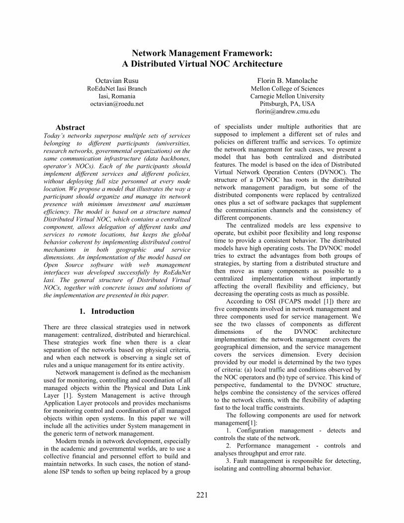
221
Network Management Framework: A Distributed Virtual NOC Architecture
Octavian Rusu
RoEduNet Iasi Branch Iasi, Romania
Florin B. Manolache Mellon College of Sciences Carnegie Mellon University
Pittsburgh, PA, USA [email protected]
Abstract
Today’s networks superpose multiple sets of services belonging to different participants (universities, research networks, governmental organizations) on the same communication infrastructure (data backbones, operator’s NOCs). Each of the participants should implement different services and different policies, without deploying full size personnel at every node location. We propose a model that illustrates the way a participant should organize and manage its network presence with minimum investment and maximum efficiency. The model is based on a structure named Distributed Virtual NOC, which contains a centralized component, allows delegation of different tasks and services to remote locations, but keeps the global behavior coherent by implementing distributed control mechanisms in both geographic and service dimensions. An implementation of the model based on Open Source software with web management interfaces was developed successfully by RoEduNet Iasi. The general structure of Distributed Virtual NOCs, together with concrete issues and solutions of the implementation are presented in this paper.
1. Introduction
There are three classical strategies used in network management: centralized, distributed and hierarchical. These strategies work fine when there is a clear separation of the networks based on physical criteria, and when each network is observing a single set of rules and a unique management for its entire activity.
Network management is defined as the mechanism used for monitoring, controlling and coordination of all managed objects within the Physical and Data Link Layer [1]. System Management is active through Application Layer protocols and provides mechanisms for monitoring control and coordination of all managed objects within open systems. In this paper we will include all the activities under System management in the generic term of network management.
Modern trends in network development, especially in the academic and governmental worlds, are to use a collective financial and personnel effort to build and maintain networks. In such cases, the notion of stand-alone ISP tends to soften up being replaced by a group
of specialists under multiple authorities that are supposed to implement a different set of rules and policies on different traffic and services. To optimize the network management for such cases, we present a model that has both centralized and distributed features. The model is based on the idea of Distributed Virtual Network Operation Centers (DVNOC). The structure of a DVNOC has roots in the distributed network management paradigm, but some of the distributed components were replaced by centralized ones plus a set of software packages that supplement the communication channels and the consistency of different components.
The centralized models are less expensive to operate, but exhibit poor flexibility and long response time to provide a consistent behavior. The distributed models have high operating costs. The DVNOC model tries to extract the advantages from both groups of strategies, by starting from a distributed structure and then move as many components as possible to a centralized implementation without importantly affecting the overall flexibility and efficiency, but decreasing the operating costs as much as possible.
According to OSI (FCAPS model [1]) there are five components involved in network management and three components used for service management. We see the two classes of components as different dimensions of the DVNOC architecture implementation: the network management covers the geographical dimension, and the service management covers the services dimension. Every decision provided by our model is determined by the two types of criteria: (a) local traffic and conditions observed by the NOC operators and (b) type of service. This kind of perspective, fundamental to the DVNOC structure, helps combine the consistency of the services offered to the network clients, with the flexibility of adapting fast to the local traffic constraints.
The following components are used for network management[1]:
1. Configuration management - detects and controls the state of the network.
2. Performance management - controls and analyses throughput and error rate.
3. Fault management is responsible for detecting, isolating and controlling abnormal behavior.

222
4. Accounting management collects and processes data about resource consumption in the network.
5. Security management deals with access control. The components of the service management are: 1. Monitoring - involves gathering data about the
network 2. Control - manipulation of devices 3. Reporting - abnormal events are reported Modern network management solutions must deal
with all components described above. The challenge consists in balancing the network management components between centralized and distributed approaches. As the DVNOC architecture and implementation will be described in the next sections, we’ll keep track of these components and of their possible distributed/centralized character or even the redundancy of some components, to balance between a clear view of the network status and the elements involved in network operation.
Section 2 describes the structure of the DVNOC architecture and information flow within management structure and Section 3 proposes Open Source software that fits into the DVNOC framework.
2. The Distributed Virtual NOC
Architecture
This Section studies the optimal architecture of a DVNOC, including the structural units, their responsibilities, and the relations between them.
Figure 1. The structural entities of a DVNOC. As shown in Figure 1, the DVNOC model implies
a series of entities that work on top of the physical network infrastructure offered by the operators. These entities take care of the implementation of the network
management components described in the previous Section.
The Network Management Coordinating Unit (NMCU) is the administrative management body that proposes and supervises the network policy, network development, and service implementation at the highest level. Some of its main functions are:
• sets up the main network policies, including the network evolution and upgrades of the equipments and services;
• establishes relations and appoints services with External Service Providers (ESPs);
• performs the high level design of all services; • decides about special solutions and services
by appropriate Special Solutions Units (SSU); • coordinates the Network Management
Executive Unit (NMEU) activities; The Network Management Executive Unit
(NMEU) is the supervising technical unit that implements the decisions and policies of NMCU. It has write access to the networking equipment and performs the following functions:
• is responsible for the technical integrity of the services provided on the network;
• implements new services using configuration solutions provided by SSUs;
• technically defines and modifies network policies;
• plans network development; • operates a Help Desk which interacts with:
o APMs; o ESP, to provide fault isolation and
management of the lines and/or services supervised by a different authority;
o SSUs during testing period for new services.
The Special Solutions Units (SSUs) are specialized task teams distributed in the service dimension, i.e. one per service or class of related services (e.g. IPv6, VoIP, etc.). One advantage of this approach is that different solutions, plans, or service implementations can be outsourced. These teams have limited access to the networking equipment and have the following main functions:
provide studies for proposed services by NMCU, specifying issues of interest for the network objectives and policies;
provide configuration files for network equipment to implement the proposed services;
interact with NMEU during service activation;
report through the Help Desk problems related to a service;
NMCU
NMEU
Help Desk
ESP # SSU #
APMs NOCs

223
monitor service operation using network management tools during the implementation period.
The Access Port Managers (APMs) are geographically distributed teams (one for each NOC) responsible for the local NOC activities. Their main functions are to:
monitor the network operation in their area of authority;
configure the local communication equipment;
monitor the implementation of the services within their NOCs;
interact with NMEU to maintain the centralized management system;
interact with the users at the NOC level. Figure 1. shows the communication channels
between different Units. The Network Management Coordinating Unit regularly communicates with the Network Management Executive Unit and the Special Solutions Units, to guarantee efficient problem solving and network operation. NMCU is also responsible for a high level interaction with the External Service Providers, dealing with issues such as ordering of new communication capacities, etc.
Network Management Executive Unit is the technical core of the management team for the entire network. NMEU is the main node of communication between management entities, interacting directly with the APMs that support the network. NMEU operates the Help Desk and a Trouble Ticket System witch is the main communication channel to NMEU. If user level support must be offered, Help Desk representatives can be distributed to the NOCs and coordinated by APMs.
Help Desk, with centralized or distributed components, must be operated by qualified personnel that should provide first level support, and should channel advanced requests to the appropriate authority via a trouble ticketing system. The NMEU, through the Help Desk group, communicates with External Service Units for fault management purposes and installation issues. Trouble Ticket System (TTS) must be unique in the entire management structure to provide a unitary consistent image of faults and events. At the same time tickets related to different types of events should go to different queues, to separate activities and to filter the right information to the right people.
The main advantage of the proposed framework is that all information flows through the NMEU to provide a centralized character to the network operation. In the same time a distributed character is achieved through APMs and SSUs: APMs provide network management and user support within a geographical area of authority, SSUs are responsible for particular services implementation on the entire
network. It should be noticed that SSUs do not interact directly with APMs. Their interaction is handled by NMCU which assures the consistency of all operations.
The next Section analyzes several implementation components of the DVNOC model.
3. Implementation. Open Source
Software
The DVONC model can be implemented for a wide range of cases where cvasi-independent networks offering different services and observing different local policies, must coexist and share hardware and human resources. Typical cases are: a national resource (e.g. a connection to an international research network) shared by joint regional networks, a campus network composed of departmental networks. The general approach does not depend on the network topology and management structure, even the implementation is mostly independent on the concrete conditions. In this Section we extracted some common tasks, features, and tools that can provide opportunities of centralized implementation for some network management components.
We considered as an important issue when distributed versus centralized strategies are weighted, the amount and the type of the traffic overhead produced by centralizing a management component. Experimental determination of an upper limit for the ICMP traffic and of the implications of large amount of UDP traffic associated with SNMP should be very useful for networks that are expected to operate most of the time close to the maximum capacity. Other related issues are the operating environment of the network management software and the amount of alarms generated when a section of the network is unreachable. Also, the security of the transactions involved by the management of distributed network devices is important: all traffic generated by management activities should be secured such that sensitive information cannot be spoofed or intercepted.
The first component of the network management, configuration management, should be implemented in a manner that allows SSUs read-only access to the configuration files of the network equipment, and write access for NMCU and APMs. NMCU and SSUs should have access to all the equipment, and APMs should have access only to devices within their area of responsibility. To provide secure access to network devices, each NOC has to provide a secure channel for each of the managed device. This is done either using an encrypted connection (SSH access) directly to the device or through a management UNIX workstation on the same secured LAN with the device. Access to the

224
management workstation is allowed only for NMEU staff and the local APM.
Read-only access is used by SSUs and can provide a fast way to directly access devices for monitoring purpose. Good tools for fast web based (read-only) access to the routers are fundamental for the efficiency of the SSUs. Such software should have the following features:
• user level access authorization; • configuration file viewer; • interfaces status and parameter viewer; • IP routing table and/or single IP route viewer; • routing protocols status viewer; • simple debugging tools (ping and traceroute); • router command line interface. A good tool for this purpose is Looking Glass [4].
Looking Glass can be installed distributed on the network, the centralized element being the web server that provides the unique interface for all managed devices. The transactions can be encrypted using https protocol. Figure 2 shows an example of Looking Glass usage though web interface.
Figure 2. Looking Glass.
The performance management component must be implemented hierarchical. This is necessary because, usually, necessary data to build reports for traffic values, error rates, CPU load device temperature. etc., are obtained using SNMP form different devices. Under a loaded network, a centralized implementation for the software used for performance management can lead to false alarms. In this respect, a distributed approach provides good results. The centralized component is achieved by using a single web based interface for the entire network. Following the Open Source approach, there are many software tools that are used for traffic and error rates reporting. In this respect, useful software is Cricket based on MRTG/RRD [6], [7] and Weathermap [5]. Both this solutions can be implemented centralized or
distributed. By using a web interface, public and private access can be offered. Figure 3 shows an example for output of Cricket.
Figure 3. Traffic monitoring with Cricket.
Reports are available based on SNMP access to devices on the network. Transaction security for this component can be achieved using SNMPv3, a new SNMP protocol framework which is already available. The security component for SNMPv3 was proposed in RFC 2274 and described by the User-based Security Model (USB). The USB model defines elements of procedures for providing SNMP message-level security, and is supposed to protect against modification of information, masquerade, and disclosure. The USB uses MD5 (Message Digest Algorithm) and the Secure Hash Algorithm to provide data integrity, to directly protect against data modification attacks, to indirectly provide data origin authentication, and to defend against masquerade attacks. Data Encryption Standard (DES) is used to protect against disclosure.
One of the most important components to be analyzed is the fault management. It consists in 3 steps: identify the problem, isolation, and correction. The first step is achieved by monitoring the network and looking for signatures of typical problems. If a signature is detected, a fault is reported (automatically or by the support personnel) to the Help Desk, issuing a trouble ticket. Depending on the importance of the problem, different entities could be required to take the appropriate decision and perform the isolation. Correction can be done either centralized or distributed

225
considering the nature of the fault and area of authority.
An important component that can be centralized is monitoring. Good monitoring is essential for fast fault isolation. Specialized tools are needed for: monitoring of host, routers, resources, and environment (SNMP); monitoring of network services (HTTP, SMTP, FTP). Serious monitoring software should have as many as possible of the following features:
• contact notifications - email, pager, phone.; • ability to define event handlers for service and
host events; • capability to scheduled downtime for
suppressing host and service; • web interface for viewing current network
status, notification and problem history, log file, etc.;
• support for user defined plug-ins to perform service checks;
• hierarchical user authorization for access to the web interface;
A good quality Open Source package that was tested by us and offers the above features is Nagios® [8]. An output of Nagios is shown in Figure 4.
Figure 3. Tactical Overview screen of Nagios.
Accounting management is a component that, in the most cases, uses important network resources. A distributed approach is the best solution to use to fulfill this task. There are few options for accounting management solutions using Open Source software, due to strong relation between different types of equipment involved in the final accounting scheme. A reliable package, IPaccounting, is available from Istituto Nazionale di Fisica Nucleare, Italy. Other approaches based on traffic flow are available.
Network security management implementation depends on the network structure and on the
responsibility of each NOC to the local users for the offered services. There are two aspects involved in network security management: security of the network devices and security of the network services. In consequence, network security management involves:
• a set of permissions that limits access to networking equipment by username/IP address;
• notification policies and action plans to annihilate security-related violations as e.g. DoS attacks.
There is no generally valid solution. Network security management cannot be classified as centralized or distributed. A centralized view of the entire component can lead to better network policy enforcement, but a distributed implementation of the software that is actually used for detecting and blocking network attacks is more efficient. Both, accounting management and network security management, typically use the same distributed/centralized scheme, and a common reliable solution is based on traffic flow analysis.
A very good tool for network security management is Snort, an Open Source network intrusion detection system. Snort is capable of real-time traffic analysis and packet logging on IP networks (www.snort.org). A web interface for Snort is available and permits to centralize the results at the top level of the network management still using a distributed scheme. Snort uses a flexible rule-based language to describe traffic that should be collected or passed, as well as a detection engine based on modular plug-in architecture. A real-time alerting capability is available.
Other tools that deal directly with the network equipment (usually Cisco routers) are available. Such a tool, available as Open Source, is under development by a RoEduNet team (http://zazu.iasi.roedu.net).
Finally, no centralized/distributed hybrid network management system can be implemented efficiently without a good trouble ticket system as the core of the Help Desk. The Help Desk is the main mechanism to efficiently centralize parts of the network management components.
All the problems appearing on the network are gathered by the Help Desk, and trouble tickets are issued. A trouble ticked should include the following information:
• the APM that reported the problem; • the entity that should consider solving the
problem (CNMSE and possibly some SIEs); • description of the problem. The management entity charged with a trouble
ticket will report to the Help Desk on the status of the ticket. A trouble ticket will be considered having an OPEN status as long as the problem was not solved.

226
When the problem is solved the trouble ticket will become CLOSED. For all trouble tickets that are OPEN, the Help Desk will send regular updates describing the actions that have been performed, as well as what is to be done. For obtaining this information, the Help Desk will regularly communicate with all involved parties (NMEU, SSU and APMs).
The most useful features of a good ticket system are:
• web-based interface with user level authentication;
• support of multiple queues (administrative, technical, etc.);
• interface for ticket submitting and operation via e-mail;
• granular user access control (requestor, watcher, admin, owner, etc.);
• SQL database storage system; • hierarchical ticket linking system (parent-
child relationships); • customizable templates for system messages. We had a good experience with Request Tracker
(http://www.bestpractical.com/rt/) that provides all the above features.
4. Conclusions DVNOC framework, based on a centralized/distributed approach of functions to be fulfilled by a network management infrastructure, is proposed. This framework establishes the responsibilities of each unit involved in the management of a network structure with branches spread over a large geographical area and offering services to a number of different institutions.
The DVNOC model for network management offers good opportunities to optimize both the
performance and the operating costs of multiple networks using the same communication infrastructure. Due to the precise split of functions to different groups, and to the optimization of communication channels, a DVNOC architecture can be implemented using a mix of distributed and centralized strategies. To help realize such a mix, several free software packages were tested by the authors and are recommended. An important advantage of this approach to be emphasized: operation of NOCs and even the service implementation procedures are distributed and can be outsourced.
We recommend the implementation of such a model for the management of fluid network structures, such as research and governmental networks, which have fluctuating operating budget provided by different sources and are offering an ever changing set of services to communities with heterogeneous resources.
References
[1] Udupa, Divakara K., Network Management System Essentials, McGraw-Hill, U.S.A., 1996.
[2] Udupa, Divakara K., TMN-Telecommunications Management Network, McGraw-Hill, U.S.A., 1999.
[3] Stallings W., SNMP and SNMPv2: The Infrastructure for Network Management, IEEE Communications Magazine, March 1998.
[4] http://www.version6.net/ [5] http://www.indiana.edu/ [6] http://cricket.sourceforge.net [7] http://people.ee.ethz.ch/~oetiker/webtools [8] http://www.nagios.org

227
New Networking Technologies in Control Applications
Gheorghe Sebestyen Technical University of Cluj
dr. Kalman Pusztai Technical University of Cluj [email protected]
Abstract
Today, communication aspects play a significant role in the implementation of distributed control applications. New networking technologies are needed to fulfill the specific communication requirements of control systems. The present article analyzes different issues and possible solutions concerning the communication in an industrial environment. A set of requirements, specific for control applications, such as reliability control, real-time message transmission and transparent access to distributed resources, are studied from the communication point of view. The next part is an overview on the networking technologies used today in industrial applications underscoring the differences between these technologies and the technologies used on the Internet. The next chapter argues about the possibility to use Internet specific technologies for control application purposes.
1. Introduction
As control applications become more and more complex, a communication infrastructure is needed, to assure data exchange and synchronization between physically distributed control devices. Some important features of control applications, such as reliability, fault tolerance and real-time behavior, must also be imposed to the communication tools [1].
For this reason new communication tools and technologies are required for the control and industrial domain. Some technologies used in general-purpose applications, in an internet/intranet environment may be also adapted for this purpose.
The present article analyze the specific requirement of generic control applications and based on the conclusions of this analysis propose some new communication solutions.
1. Communication requirements in control applications
Modern, computer-based control systems involve a great number of devices distributed on a significant area. These devices must exchange information in order to fulfill the specific control functionality of the system.
In early computer-based control systems, field devices (sensors, actuators, PLCs, etc.) were connected to a central computer through a set of dedicated links. Hierarchical control architectures were also using dedicated connections. Such a solution has low reliability and fault-tolerant architectures are difficult to build. Cabling costs are big and system reconfigurations are limited.
Computer networks seamed to offer the solution for these issues. A single bus or ring network may connect all the elements of a control system. The system is scalable, new devices can be connected in the system without any change in the existing structure. But the communication protocols developed for general-purpose computer applications don’t fulfill a number of requirements that are critical for a control system. These protocols are design to assure high bandwidth and maximum average throughput, with limited or no control on reliability, and time constraints.
For this reason general-purpose networks and communication protocols were considered not adequate for critical control applications.
The following features are considered important for a control system’s communication infrastructure:
a. Reliability is a critical aspect in any autonomous system. It is not only a quality feature; the designer must guarantee a certain level of reliability for the control system to be accepted. An important part of the equation is the reliability of the data transmission. The communication protocol must include advanced error detection and correction mechanisms for all the defect scenarios (except for those considered catastrophic [2]). Any protocol based on non-deterministic

228
mechanisms (e.g. collision-based media access) are not accepted. The protocol must offer the means for an analytical evaluation of the reliability level [9] It must also offer redundant solutions in case of defects.
b. Real-time behavior is another important aspect in any control application. The correctness of a control algorithm depends equally on the correctness of the calculus and on the fulfillment of time restrictions. Control tasks have more or less critical deadlines (hard and soft deadlines), which must be met. In a distributed system tasks communicate with each other and the response time on the system depends also on the data transmission time. The communication protocol must assure transmission of critical data, in a predefined time interval. For this reason a message scheduling policy must be used. There are a number of industrial protocols (fieldbuses) that offer the support for a scheduling algorithm implementation. A number of studies were made to determine the timely behavior of different fieldbus protocol standards (e.g. for CAN [2,9], for TDMA [7] or for token-buses [7])
c. Deterministic behavior is required as a precondition for any reliability or real-time analysis. Protocols used for control purposes must have a well-defined functionality for any possible situation; no random or concurrency-base solutions are acceptable. For instance any collision-based protocols should be avoided. Strictly deterministic behavior may be considered rigid and less efficient for general-purpose networks, but is preferred in control applications. Master-slave or token-based network access control mechanisms are preferred.
d. Specific data structures and data flows must be transmitted through a distributed control system. Usually, simple data structures, such as process parameters (digital and analog variables), events or configuration data represent the content of messages transmitted between control devices. The length of the useful data in a message may be from a few bits (see ASi or CAN protocols) to hundreds of bytes. For this reason the protocol should be optimized for short or very short messages, by reducing the length of the message overheads. Another aspect is the frequency pattern of different message types. In a control applications data transfer is highly periodical. For this reason protocols must have support for periodical message transfer specification and timely delivery.
e. Interoperability between different automation devices, very different in type, functionality, capabilities and computing resources is another issue. The communication protocol must allow the integration of simple control devices with limited resources (e.g. intelligent sensors and actuators). The protocol stack should be simple enough to fit into a limited memory space of only a few kbytes. In the same time the protocol should be open for intranet/internet access requests.
f. Other special requirements may be imposed for specific industrial environments, such as: good immunity to higher electro-magnetic noises, intrinsic protection against explosion, networking in hazardous areas, data transmission on power supply lines, etc. The networks used in an industrial environment must assure the security requirements of the specific area and should be robust to changes of environmental changes.
All these requirements show that general-purpose networks and communication protocols cannot be used directly in control applications. Special protocols are needed for industrial environments that fulfill the above conditions.
In the same time control applications must be integrated into the information system of a company and process information must be accessed remotely using Internet technologies. So further efforts are needed to merge the field of industrial communication into the more general Internet environment. In the next chapters some of the issues concerning this “merge” are discussed.
2. Networking in control applications
The use of networks as support for data transfer in control systems is rather new. In the last 10-15 years a great number of communication protocols and standards were proposed. The lack of a generally accepted framework (such as the OSI for the computer networks) and the wide range of control applications, very different in their requirements, lead to a wide range of protocols, which are not compatible with each other. Every significant producer in the automation devices’ market tries to impose their own protocol.
The need for a common framework was accepted both by the producers and by the system integrators and control system developers [3]. But the theoretical and practical efforts made in the last 5 years in this direction have not been successful yet. One objective reason is the very wide variety of control applications with very different communication requirements. Probably a single protocol stack cannot solve all the particular cases. A better approach is to divide applications into 3

229
main classes, according to their communication requirements:
- instrumentation or local loop level control - process level control - global optimization level control According to this classification three main
control network classes may be defined: - actuator and sensor networks - fieldbuses, and - cell networks The first class contains protocols used for data
exchange between simple automation devices like sensors or actuators and medium complexity devices like regulators or PLCs (Programmable Logic Controllers). These protocols are simple enough to fit into the limited resources of a simple device. The message transfer is optimized for very short telegrams of only a few bits. Examples of such protocols are: ASi, CAN, Interbus-S, etc.
Fieldbuses are medium complexity networks used to control an industrial process or a complex equipment (e.g. a robot). The protocols assure good reliability and short reaction time. The most used protocols from this category are: Profibus, WorldFIP, Fieldbus-Fondation, P-Net, DeviceNet, etc.
The last class contains networks meant to connect flexible production cell, for global optimization purposes. These networks are similar with LANs, they have a higher degree of determinism and reliability. These networks can be integrated into an intranet/internet architecture.
3. Internet technologies in control applications
Even if industrial protocols offer good solutions for a wide class of control application, the need for remote control, for globalization and for uniform access to process data urge the use of Internet technologies also in the control field.
This problem has a number of aspects and involves solutions at different levels. The first approach is to use LAN protocols for control purposes. A number of articles argue upon the possibility to use Ethernet in an industrial environment. The problem is that Ethernet has a collision-based multiple access protocol (CSMA/CD), which make it very unpredictable and its behavior non-deterministic. Some articles showed that in high speed Ethernet networks (<=100 MHz) the probability of multiple collisions may be kept extremely low if the traffic pattern is known [5,11].
Another proposed solution is to implement a deterministic media access control above the Ethernet layer [11]. For this purpose the Mod-Bus protocol was proposed. In this way a widely used technology, the Ethernet, can be adopted also for the control field.
Another important issue is the lack of support for time control in the Internet protocol stack. There are some so-called real-time protocols, but these are meant only for multimedia transmissions. In multimedia transmissions, as in the case of control applications, periodic data flow plays an important role. A good multimedia transmission must preserve the frequency of the transmitted data. But small deviations from this request are not critical, they contribute to the degradation of the transmission’s quality. In contrast, for control applications any deadline-lose may be critical.
There is no global solution to this problem. For some restricted areas (intranets), the traffic can be strictly controlled and in such conditions time restrictions may be solved. There is also a possibility to reserve enough bandwidth on a dedicated communication channel, which can assure a timely transmission in the worst possible case. But usually control functions with small reaction times are not implemented through long distances on an Internet environment; these functions are implemented in local devices connected on an industrial network. These devices may be accessed from a remote place, using the Internet, but these accesses are usually not time-critical. On long term probably the automation community has to be more involved in the process of protocol standardization on the Internet. The introduction of the new IP6 protocol is a first step in this direction. This protocol contains more possibilities to control the quality of the services supported by the Internet.
Another important issue concerning the integration of the control applications into an Internet environment is the remote access to process data. Most access methods used today on the Internet consider remote resources as static data. Most information on the Internet is preserved in files, stored in static storage devices (web pages, ftp formats, asp or cgi files, etc.). Process information is more dynamic; it is preserved usually in the internal memory of a control device, and its value is permanently changed according to the changes in the controlled process. For this reason new access mechanisms are needed, which are using a uniform naming system.
The naming system must follow the structure and the organization of typical process data in devices, equipment, and flexible process cells. An object-oriented approach is recommended. The naming system must assure transparent access to a wide variety of control devices, without type or producer restrictions. The next paragraph presents a feasible solution to this problem.
Another approach to the remote control problem is the implementation of a minimal TCP/IP protocol stack and Web server on systems with very limited computing resources (10-20MHz, 32kbyets program memory, 1024 bytes data memory). In this way any control device can be connected directly on the

230
Internet. The access to its resources is made through HTTP protocol, using web pages. For instance a microcontroller (e.g. PIC 16C877) and an Ethernet controller may be the hardware support for any embedded system, connected on the Internet. The TCP/IP protocol stack’s higher levels are implemented in the internal memory of the controller and the low-level protocols in the Ethernet controller. Only a limited version of the TCP/IP protocols are implemented and a number of restrictions has to be imposed.(e.g the maximum length on an IP message is just 1kbyte), due to the small available internal memory.
Mobile communication technologies such as Bluetooth (radio transmissions), mobile phones, or IrDA (Infrared Data Adapter) may be used to connect control devices to computer systems or directly to the Internet. Such technologies may be a solution for hazardous areas, for isolated measuring stations or for ad-hoc control systems.
4. Communication models
For general-purpose applications (e.g. distributed databases, banking, interpersonal communication, etc.) a number of communication models and programming tools were developed and successfully used. The most used models are: the client/server model, the remote process calls (RPC), the object-based transparent access model (CORBA, COM and DCOM), web-based access (HTTP, CGI, XML, etc.), mobile agents, and others. The question is if these new models and tools can be used also for control applications. The answer to this question is neither simple nor unique.
Communication models used in control applications must offer better support for periodic data transfer (e.g. for data acquisition and control generation), for priority specification and for delay measurement and control. Typically used communication models are:
- the consumer/producer model - the master/slave model - the time scheduled communication – a time
slice is allocated for every network node - the virtual manufacturing device model In the producer/consumer model “producer”
nodes transmit periodical information concerning the process variables managed by them and one or more “consumer” nodes may receive the information; a given network node may be in the same time a producer for some variables and a consumer of others. This model assures a periodic data flow, location transparency and a certain level of fault tolerance.
In the master/slave model, master nodes have the ability to initiate data transfers, sending or requesting data to or from slave nodes; the complexity of the communication protocol is concentrated in the master nodes, requiring small
resources for slave nodes. This model is recommended in industrial networks, where a wide range of automation devices is involved, with different processing capabilities.
The time-scheduled model is preferred in time critical applications, where a certain periodic data flow must be assured. An off-line transmission schedule is defined, that can guarantee the fulfillment of message transfer deadlines.
The virtual device model offers a class of virtual objects adapted to the needs of a control application (e.g. input/output signals, event objects, program and context objects) and a standard data/service access interface. This model solves the compatibility, interoperability and interchangeability issues between different types of automation devices.
These communication models are easy to implement on a local network, but there are much harder to use on an intra- or inter-net environment. In the latest networks there is a pour control on the quality of services and the communication load patterns are unpredictable. This is caused by the fact that the process control data must be mixed with an unknown data flow.
But on the other hand, there is a significant demand for Internet-based distributed applications. End-users want to visualize and control their production facilities through the Internet. Therefore new models are needed, models that are common for the Internet environment.
5. A service-based solution for distributed control
To solve the issues concerning the communication and synchronization in complex control systems, a distributed service-based framework is proposed. In this approach a number of generic control functions are implemented as distributed services:
- the resource management service - the global time service - the event management service - the data acquisition service - the process supervision service One of these services is concerned with process
data access management. This service is responsible for identifying and managing all the resources of a given distributed control system. Any access request (read/write, set/reset, etc.) to a process variable, named with a symbolic name is translated into an access to a physical device.
The actual address or position of the physical device remains transparent to the requester. In this way the system may be dynamically reconfigured without any change in the upper application levels. The access service is implemented as a server, which can accept requests through an Internet connection.

231
In our implementation the service is implemented as a set of local servers, which cooperate through a specific protocol. Every local server is responsible for those resources (process variables) which are directly connected to the device where the server is executed.
The time service is responsible for maintaining a global time reference for the whole system. This service is needed to establish correct causal relationships between events. It is also used to register events with time stamps, for later analysis. The local timers’ synchronization algorithm takes into account the maximum time deviations allowed by the control procedure.
Another important service is responsible for events’ detection, registration and notification. Many control systems are designed as reactive systems, which means that it reacts to any changes detected in the controlled process. For this reason the existence of an event management service is essential for an efficient design of a control application. The service was implemented as a set of local event detectors. Every detector is responsible for all the events concerning the device to which is attached. The occurrence of a given event is notified to a predefined list of distributed tasks.
The data acquisition service determines and preserves the image of the actual state of the controlled process. Every process variable is periodically tested. There are different data acquisition procedures depending on the variable’s nature and frequency. The gathered information is available for any application developed upon this service.
All these services are accessible through Internet. A number of applications may use the same service set. These services represent the middle tire in a three-tire architecture: application – services – control devices.
This approach offer a number of advantages: - all the implementation details concerning
process interfaces, devices, access methods, etc. are embedded in the services;
- separation of control functions makes the implementation of distributed control applications an easier task
- changes at the process level have a minimal impact at the application level
- redundant and fault-tolerant structures may be built
5. Conclusions
Modern design of distributed control application requires an adequate communication infrastructure. Specially designed industrial networks may be used for this purpose. These networks have features adapted to the requirements of control applications. But the integration of such networks into an Internet environment is a difficult task.
Internet technologies may also be adapted for control purposes. The proposed service-based approach is a feasible solution to this problem. But the use of Internet protocols in process control is still in an incipient stage. New protocols and standards are needed to cover the issues concerning the implementation of distributed control systems.
6. References
[1] C. Cardeira. , F Simonot-Lion, M.Bayard, “ Intelligent Field Devices and Field Buses: Impact on Applications Design Methodology”, Studies in Informatics and Control Vol 4 No. 3, pp 255-262 [2] L.B.Fredriksson , “Controller Area Networks and the Protocol CAN for Machine Control Systems”, Mechatronics , Vol. 4 No.2 pp 159-192, [3] S. Koubias, G. Papadopoulos, “Modern Fieldbus Communication Architectures for Real-Time Industrial Applications”, Computers in Industry journal (ELSEVIER) Vol. 26 pp. 243-252 [4] F. Momal, R. Saban, P. Sollander, “ Integrating a Commercial Industrial Control System to the Accelerator Control System", Proc. ICALEPCS 1993, Berlin, p 464, [5] R. Mackiewicz, R. Daniel, “Ethernet TCP/IP: An effective real-time agent with a track record” Control Software Forum, I&CS Magazine, 1999 [6] R. Pasadas , L. Almeida. Fonseca J. [1997], “ A Proposal to Improve Flexibility in Real-Time Fieldbus Networks “ IFAC SICICA ‘97 , 3rd IFAC Symposium on Intelligent Components and Instruments for Control Application , Annesy, Franta [7] Ghe. Sebestyen , A Real-Time Communication Protocol for Distributed Control Systems, Proc. SINTES’98, Craiova,1998 [8] Ghe. Sebestyen, G. Buzas “Internet Technologies for Remote Process Control and Supervision” OSPMA-FieldComms99 Conference, Open Solutions for Process and Manufacturing Automation, London, UK, 2000 [9] Tindell, J. Clark, Holistic Schedulability Analysis for Distributed Hard Real-Time Systems, Microprocessors and Microprogramming 40, 1994 [10] Q. Zheng, K.G. Shin, “On the Ability of Establishing Real-Time Channels in Point-to-point Packet-Switched Networks”, IEEE Trans. on Communications, 42(2/3/4). 1994 [11] **** Industrial Ethernet, A White paper, Synsrgetic Communication Technology, 1999, http://www.industrialethernet.com

232
Heterogeneous Networks Management System having GIS and Web Based Interfaces
Veaceslav Sidorenco Technical University of Moldova
Vladimir Ciclicci, Sergei Dolenco Systemcomputer Ltd.
Abstract
Paper describes particularities of architecture of wide area telecommunications management network (TMN) and system (TMS) RomTMN HD that are developed by specialists from Technical University of Moldova and Systemcomputer Ltd. for Direction of Telecommunications of Romtelecom (Hunedoara County, Romania). Core modules of RomTMN HD are implemented on the base of original geoinformation model of telecommunications systems. The architecture of TMN and TMS is based on M series of ITU-T Recommendations and uses modern concepts of implementation of distributed objects management like DCOM - Distributed Component Object Model, WBEM - Web Based Enterprise Management and GIS - Geoinformation Systems. RomTMN HD being automated and integrated management system is capable to improve all complex set of processes of coordination of resources necessary for supervision, monitor, projection, simulation, generation, implementation, analysis, measurement and test of telecommunications networks in order to warranty to end users high level of services, at adequate price and optimal distribution of capacities. 1. Management of telecommunications objects
Main trends of modern information systems progress can be denoted as having well-defined orientation toward stable increasing of the degree of system's complexity, of the intensity of systems interaction and co-operation using information exchange channels and telecommunications interfaces, and of degree of human-machine interface naturalization (visualization). Modern TMN and TMS must be based on visual management technologies: they must be able to deal visually with a wide range of telecommunication systems beginning from simple local area networks
and ending with global Intellectual Networks, Internet and wide area virtual private corporate networks. One of possible way to implement visualization paradigm consists in integration of TMN with geoinformation systems.
Telecommunications system of Romania consists of a set of distributed equipment, interconnected by cable links that provides solutions for reliable transportation of information between customers of telecommunications services. Telecommunications networks of Romania represent typical examples of heterogeneous structures, having a mixture of different switching, multiplexing and concentration techniques. It is very important to create an integral management system capable to deal with information technologies objects distributed over large geographic areas. National and regional telecommunications operators must manage available resources using standard procedures. This will results in increasing of the potential and quality of telecommunications services, and in decreasing of non-justified payments. Consequently the perspective to shift toward using new generation of intelligent networks will be open. The hierarchy of management systems can be divided into a sequence of 4 layers in correspondence with goals of services (fig. 1).
First layer L1 is oriented for implementation of network elements (NE) management functions using own internal agents or external agents built as Q-Adaptors (QA). Second layer L2 is used for management of networks resources as a result of controls gotten from layer L3 from services management or from fault messages analysis gotten from agents of layer L1. The activity from layer L2 results in modifications of performance, capacity and topology and other parameters of networks under management. Third layer L3 disposes to users all the spectrum of own and external telecommunications services. Fourth layer L4 deal with strategic plans in development and using of telecommunication resources and services.

233
Business
Servicii
Network
Network element
$L4:
L2:
L1:
L3:
Services
Figure 1. Hierarchy of layers of
telecommunications management 2. Objects under management in Hunedoara county (Romania)
Hunedoara County owns a complex set of telecommunications resources of national and regional level. Geographic position of County in Romania is shown on fig.2.
Figure 2. Position of Hunedoara County in
National Telecommunications system of Romania On the surface of 7,025 square km there are
about 0.55 millions inhabitants distributed in next proportion: 71 % lives in urban regions and the rest of 29% - in rural one. All managed objects from Hunedoara County can be divided in next categories (fig. 3): • Transmission system (TS), having transport
channels and channel-level operation equipment: - fiber optics national backbones BB1, BB3 :
288 km; - regional rings of fiber optics TIM1,TIM2 :
157 km;
- Local fiber optics lines: 197 km.
- STM16 (Philips), STM4 (Philips, Fujitsu), STM1 (Alcatel),
- PDH (Alcatel, Ericsson); - Symmetric cables: 680 km; - Analog circuits: 1066 (33%); - Fiber optics cable: 360 km; - Digital circuits: 2170 (66%).
• Switching systems (SS), formed from Exchanges, satellites, hand switched operator assisted nodes, local distribution systems having integral capacity of 89900 units and 71500 connected lines: - 9 digital exchanges ("Alcatel" - 3 with 13
satellites, "Ericsson" - 2, "Topex" - 3, "Goldstar" - 1), 62400 served units;
- 30 analog exchanges ("Pentaconta" - 9, "Topex" - 3, "Pentomat" - 18), 25800 served units;
- 8 hand switched exchanges, 1700 served units.
Figure 3 Telecommunications objects in
Hunedoara County, Romania
3. RomTMN HD system architecture The management system for such complex set of
telecommunications objects is hierarchical having four level of management. Automated and integrated management system is capable to improve all ensemble of processes of coordination of resources necessary for supervision, monitor, projection, simulation, generation, implementation, analysis, measurement and test telecommunications networks in order to warranty to end users high level of services, at adequate price and optimal distribution of capacities. The structure of RomTMN HD, a new Regional TMS for Hunedoara County, developed
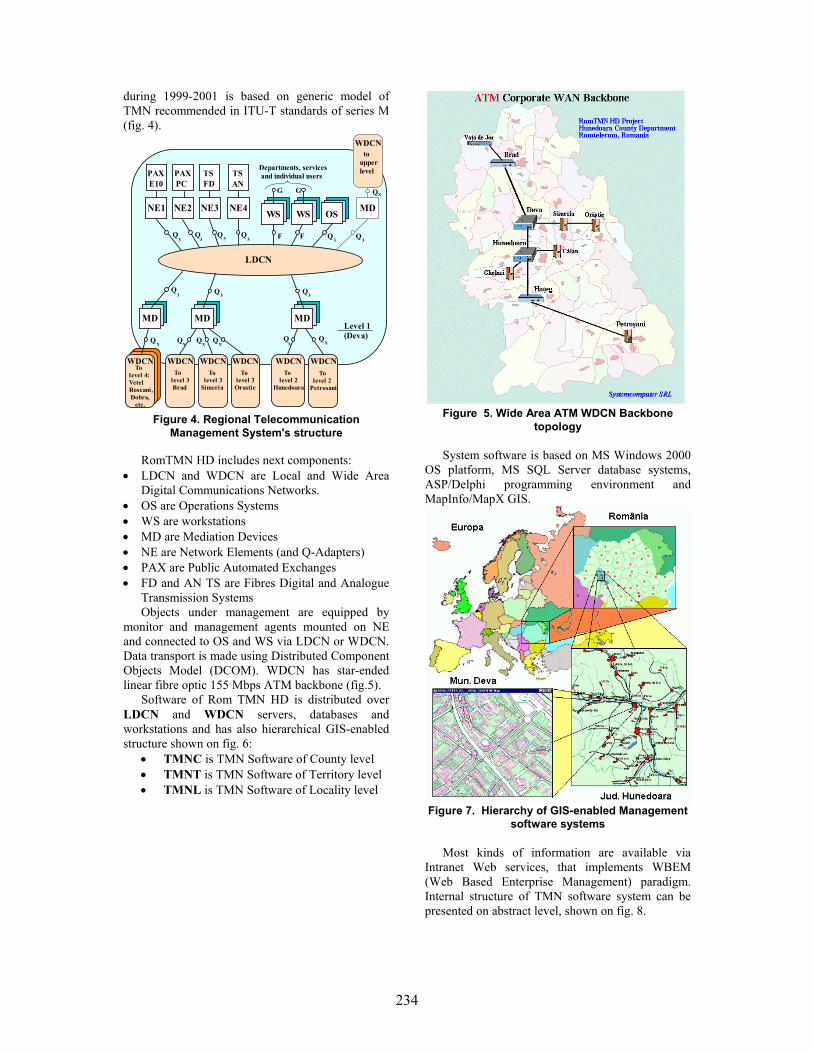
234
during 1999-2001 is based on generic model of TMN recommended in ITU-T standards of series M (fig. 4).
NE1 NE2 NE3 NE4 WS WS OS MD
LDCN
MD MD MD
PAXE10
PAXPC
TSFD
TSAN
WDCN
WDCNWDCNWDCNWDCN WDCNWDCN
Level 1 (Deva)
Departments, services and individual users
toupperlevel
Q
QQFFQQQQ
Q Q Q
Q Q Q Q Q Q
G GX
X X X X X X
3 3 3 3 3 3
333
Tolevel 4:VetelRoscani, Dobra, etc.
To level 3 Brad
To level 3Simeria
To level 3 Orastie
To level 2Hunedoara
To level 2Petrosani
Figure 4. Regional Telecommunication
Management System's structure
RomTMN HD includes next components: • LDCN and WDCN are Local and Wide Area
Digital Communications Networks. • OS are Operations Systems • WS are workstations • MD are Mediation Devices • NE are Network Elements (and Q-Adapters) • PAX are Public Automated Exchanges • FD and AN TS are Fibres Digital and Analogue
Transmission Systems Objects under management are equipped by
monitor and management agents mounted on NE and connected to OS and WS via LDCN or WDCN. Data transport is made using Distributed Component Objects Model (DCOM). WDCN has star-ended linear fibre optic 155 Mbps ATM backbone (fig.5).
Software of Rom TMN HD is distributed over LDCN and WDCN servers, databases and workstations and has also hierarchical GIS-enabled structure shown on fig. 6:
• TMNC is TMN Software of County level • TMNT is TMN Software of Territory level • TMNL is TMN Software of Locality level
Figure 5. Wide Area ATM WDCN Backbone
topology System software is based on MS Windows 2000
OS platform, MS SQL Server database systems, ASP/Delphi programming environment and MapInfo/MapX GIS.
Figure 7. Hierarchy of GIS-enabled Management
software systems Most kinds of information are available via
Intranet Web services, that implements WBEM (Web Based Enterprise Management) paradigm. Internal structure of TMN software system can be presented on abstract level, shown on fig. 8.

235
Figure 8. The structure of Regional TMN Software
System Figures 9 to 12 illustrates samples gotten as
screenshots from main management services, that are implemented as ASP and ActiveX components, used inside of Intranet Server web-pages and containing next generic management services: • Configuration management; • Performance management; • Fault management; • Account management and • Security management.
Figure 9. Configuration management system
Figure 10. Performance management system
Figure 11. Fault management system
Figure 12. Account management system
The interaction of thin (IE-based) clients with
web server uses SOAP technology that gives the possibility to introduce MS dotNET solutions into project future development.
4. Conclusion DCOM and WBEM based Telecommunications
Management system with Interactive Geoinformation sub-systems incorporated into TMN architecture gives the possibility to significantly increase integral efficiency and spatial accuracy of management procedures. Networks under management configuration and current state monitoring become spatially "natural" for managers. They can easily browse inside managed object space. GIS also provides good possibilities for networks topology optimisation and future planning
5. References [1] TMN Today. The Telecommunications Management Solutions Newsletter. Fall 1998. Vertel. 8 p. [2] ITU-T M-Series Recommendation M.3010 Principles for a Telecommunications Management Network. COM 4-49-E. Revised 1996. 97 p. [3] Ciclicci V., Dolenco S., Sidorenco V., The Architecture of National Integrated Telecommuni- cations Management System. Acta Academia, 1998, Chisinau: Evrica, 1998. P. 100-107.

236
Using XML-RPC in Secure Database Administration on the Web
Silvana Solomon Department of Digital Communications University “Al.I.Cuza” of Iasi, Romania
Catalin Varvara RoEduNet Iasi Branch
Abstract
XML-RPC is a Remote Procedure Calling protocol that works over the Internet. An XML-RPC message is an HTTP-POST request. The body of the request is in XML. A procedure executes on the server and the value it returns is also formatted in XML. Procedure parameters can be scalars, numbers, strings, dates, etc.; and can also be complex record and list structures. The goal of this protocol is to lay a compatible foundation across different environments, no new power is provided beyond the capabilities of the CGI interface. Firewall software can watch for POSTs whose Content-Type is text/xml. We use the XML-RPC technology in order to securely transfer database contents on the Web.
1. Introduction
The world gets more and more interconnected nowadays. People communicate by means of computers and there is a strong need for easy, reliable means to control and use the facilities offered by a remote machine.
In a stand-alone computer, applications use procedure calls in order to realize their tasks. The same type of service is needed to make use of the capabilities that are accessible from other computers. For example, a computer can provide a service whereby it receives a number representing the year and after some calculations it returns the date of Easter for that year. Both the server machine and the client machine have to agree on the types and number of parameters to be passed and returned as well as on other details. For this, Remote Procedure Call or RPC was created.
2. RPC and XML-RPC 2.1. Overview
RPC is a very simple extension to the procedure
call idea. It creates connections between procedures
that are running in different applications, or on different machines [3].
Conceptually, there's no difference between a local procedure call and a remote one, but they are implemented differently, perform differently and therefore are used for different tasks. RPC is much slower than a local procedure call because of the time required to establish the connection and for communication.
Remote calls can be understood on both sides of the connection because the two machines implement the same protocol. The value in a standardized cross-platform approach for RPC is that it allows Unix machines to talk to Windows machines and vice versa.
There are numerous possible formats for RPC. XML is a language that had a tremendous development and it has a lot of applications in almost every aspect of computer science. RPC made no exception and the two technologies combined to yield a powerful instrument that can be used on the Web. This is how XML-RPC appeared. XML-RPC is a specification and a set of implementations that allow software running on disparate operating systems, running in different environments to make procedure calls over the Internet. It is remote procedure calling using HTTP as the transport and XML as the encoding. It is designed to be as simple as possible, while still allowing complex data structures to be transmitted, processed and returned.
In XML-RPC, it is easy to pass and return complex data types: arrays or structs can be employed as simple as primitive data types. This way, one can call procedures with very complicated and elaborated returned values or parameters. To what concerns the latter, they can be strongly typed. It is worth mentioning that the use of XML makes it easy to learn and implement.
Up to now, there are known implementations in several programming languages. Servers are available for PHP, Frontier, Java, Perl, Tcl and Zope. Client implementations are available for PHP, Frontier, COM, Perl, TCL and Python. There is support for XML-RPC in web browsers such as Netscape.

237
2.2. XML-RPC vs. SOAP
SOAP (Simple Object Access Protocol) is a protocol for exchange of information in a decentralized, distributed environment. It is an XML based protocol that consists of three parts: an envelope that defines a framework for describing what is in a message and how to process it, a set of encoding rules for expressing instances of application-defined datatypes, and a convention for representing remote procedure calls and responses. SOAP makes extensive use of namespacing and attribute specification tags in almost every element of a message. It implements user defined data types, the ability to specify the recipient, message specific processing control, and other features.
While XML-RPC wants only to perform remote procedure call at a simple level, still remaining not complicated in format, SOAP reaches for more complex features and has more capabilities. For example, it has named structs and arrays, polymorphic ancestors and enumerations. In XML-RPC, an <array> contains a single <data> element, which can contain any number of <value>s.
The most important feature of XML-RPC is its simplicity. As the authors themselves state, it should be an easy to implement protocol that could be quickly adapted to run in different conditions. On the other hand, SOAP goes further and addresses detailed questions and therefore it has more features. Naturally, there is a trade-off for all these. XML-RPC is easy to use but has fewer capabilities, while SOAP provides more utilities and it is less natural to use [2].
SOAP involves significantly more overhead but adds much more information about what is being sent. If complex user defined data types and the ability to have each message define how it should be processed is needed, then SOAP is a better solution. Yet if standard data types and simple method calls are enough then XML-RPC makes applications faster and easier to debug and maintain.
2.3. Current Implementations
XML-RPC is currently implemented and used in numerous applications that need to call applications from machines in a network.
Web Crossing is well-known collaboration server platform [6], offering complete solutions and many features. It uses XML-RPC to share resources from a Web Crossing server, and to let a server access shared resources from other servers. It has the built-in ability to act as both an XML-RPC server and client. Through XML-RPC, a server can act as a client for another server. Also it allows to create new clients separate from a browser, to share information among servers and to make search requests on multiple co-operating servers.
VisualOffice is a web-based groupware solution [5] that enables a company’s staff to access their e-mails and collaborate on many tasks from one central location accessible anywhere in the world at anytime. VisualOffice uses XML-RPC internally to exchange information between the different modules, and externally to retrieve information such as news, weather, stocks, etc. For instance, it can get information from each one of them and display a summary of the events, tasks and folders that the user has. Using XML-RPC, VisualOffice can also retrieve external information from news feeds such as television channels and display it to the user. 3. XML-RPC for PHP
We use a collection of PHP classes that provides a framework for writing XML-RPC clients and servers in PHP.
Files in the distribution are: xmlrpc.inc - the XML-RPC classes. We must
include this in our PHP files to use the classes. xmlrpcs.inc - the XML-RPC server class. We
must include this too in addition to xmlrpc.inc to get server functionality
The two above classes are used as libraries, and are not to be modified. The other next two classes are used in order to create XML-RPC client and server, using the two libraries.
server.php - a sample server hosting six functions: 5 functions in order to decode the struct and to create the mySQL command, and one to execute and to return the result of one query.
client.php - client code to exercise the various functions in server.php
Xmlrpc_client - the basic class used to represent a client of an XML-RPC server.
Creation The constructor has the following syntax: $client=new xmlrpc_client($server_path, $server_hostname, $server_port); In our example client set up to query the server
with the IP address 192.168.3.188: $client=new xmlrpc_client("RPC/server.php", "192.168.3.188", 80); The server_port parameter is optional, and if
omitted will default to 80 when using HTTP and 443 when using HTTPS.
The methods of this class used in the project are : send This method takes the form: $response=$client->send($xmlrpc_message, $timeout, $server_method); where $xmlrpc_message is an instance of
xmlrpcmsg, and $response is an instance of xmlrpcresp.
The $timeout is optional, and will be set to 0 (wait forever) if omitted.

238
The server_method parameter is optional, and if omitted will default to 'http'. The only other valid value is 'https', which will use an SSL HTTP connection to connect to the remote server.
setDebug $client->setDebug($debugOn); $debugOn is either 0 or 1 depending on whether
you require the client to print debugging information to the browser. The default is not to output this information.
The debugging information includes the raw data returned from the XML-RPC server it was querying, and the PHP value the client attempts to create to represent the value returned by the server. This option can be very useful when debugging servers because it allows you to see exactly what the server returns.
xmlrpc_server The current implementation of this class has
been kept as simple as possible. The constructor for the server basically does all the work. Here's a minimal example:
function my_select ($params) ... $s=new xmlrpc_server (array("DB_select" => array("function" => "my_select", "signature" => $my_select_sig, "docstring" => $my_select_doc) ) ); This performs everything you need to do with a
server. The single argument is an associative array from method names to function names. The request is parsed and despatched to the relevant function, which is reponsible for returning a xmlrpcresp object, which gets serialized back to the caller.
The first argument to the xmlrpc_server constructor is an array, called the dispatch map. In this array is the information the server needs to service the XML-RPC methods you define.
The dispatch map takes the form of an associative array of associative arrays: the outer array has one entry for each method, the key being the method name. The corresponding value is another associative array, which can have the following members:
• function - this entry is mandatory. It must be a name of a function in the global scope which services the XML-RPC method.
• signature - this entry is an array containg the possible signatures for the method. If this entry is present then the server will check that the correct number and type of parameters have been sent for this method before dispatching it.
• docstring - this entry is a string containing documentation for the method. The
documentation may contain HTML markup. Method signatures. A signature is a description
of a method's return type and its parameter types. A method may have more than one signature.
Within a server's dispatch map, each method has an array of possible signatures. Each signature is an array of types. The first entry is the return type. For instance, the method
my_select(struct) has the signature array($xmlrpcString, $xmlrpcStruct); and, assuming that it the only possible signature
for the method, it might be used like this in server creation:
$my_select_sig=array(array($xmlrpcString, $xmlrpcStruct)); $my_select_doc='When passed a struct containing the parameters of an SQL command, it constructs the query, interrogates the BD and returns the query's result, where the tbl_id is actually the corresponding index of the interrogated table, in an array.'; For convenience the strings representing the
XML-RPC types have been encoded as global variables:
$xmlrpcI4="i4"; $xmlrpcInt="int"; $xmlrpcBoolean="boolean"; $xmlrpcDouble="double"; $xmlrpcString="string"; $xmlrpcDateTime="dateTime.iso8601"; $xmlrpcBase64="base64"; $xmlrpcArray="array"; $xmlrpcStruct="struct"; Fault reporting. Fault codes for your servers
should start at the value indicated by the global $xmlrpcerruser + 1.
The general idea of the project's functionality is
represented in the scheme below: A.The WebClientX will make a request to the
WebClient1 WebClient2
XML-RPC client
XML-RPC server
DB server

239
XML-RPC client through a method called show_products_ofMyCompany() for example. The XML-RPC client’s functionality is to define the request to an XML-RPC server.The WebClient does not know anything about the database location and type.
B. Next, the function which is called show_products_ofMyCompany() in XML-RPC client calls a generic function to fill the fields of a struct object, that will look like:
$select_param=new xmlrpcval (array( “field_list" => new xmlrpcval (""), "tbl_id"=> new xmlrpcval("6"), "where" => new xmlrpcval(""), "group by" => new xmlrpcval(""), "order by" => new xmlrpcval(""), "having" =>new xmlrpcval("") ), "struct"
); In our case the field_list is empty and the XML-
RPC server will take it as “*” argument of the SQL command option. Value 6 for tbl_id is the numeric correspondent of the table to be interrogated.
The next steps in the XML-RPC client are : 1. represents a request to an XML-RPC server: $f = new xmlrpcmsg('DB_select', array($select_param)); 2. creates an XML string representing the
XML-RPC message: htmlentities($f->serialize()); In the XML-RPC request, its header has the
form: POST /RPC HTTP/1.0 User-Agent: PHP/4.0.5 Host: 192.168.3.188 Content-Type: text/xml Content-length: 558 The format of the URI in the first line of the
header is not specified. For example, empty, a single slash, if the server is only handling XML-RPC calls. However, if the server is handling a mix of incoming HTTP requests, we allow the URI to help route the request to the code that handles XML-RPC requests. (In the example, the URI is RPC, telling to route the request to RPC responder.)
A User-Agent and Host must be specified. The Content-type is text/xml. The Content-Length must be specified and must
be correct. The payload is in XML, a single <methodCall>
structure. The <methodCall> must contain a
<methodName> sub-item, a string, containing the name of the method to be called. The string may only contain identifier characters, upper and lower-case A-Z, the numeric characters, 0-9, underscore, dot, colon and slash. It's entirely up to the server to
decide how to interpret the characters in a methodName.
For example, the methodName could be the name of a file containing a script that executes on an incoming request. It could be the name of a cell in a database table. Or it could be a path to a file contained within a hierarchy of folders and files.
If the procedure call has parameters, the <methodCall> must contain a <params> sub-item. The <params> sub-item can contain any number of <param>s, each of which has a <value>.
The encapsulated request for the server looks like:
<?xml version="1.0"?> <methodCall> <methodName>DB_select</methodName> <params> <param> <value><struct> <member><name>field_list</name> <value><string></string></value> </member> <member><name>tbl_id</name> <value><string>6</string></value> </member> <member><name>where </name> <value><string></string></value> </member> <member><name>group by</name> <value><string></string></value> </member> <member><name>order by</name> <value><string></string></value> </member> <member><name>having</name> <value><string></string></value> </member> </struct></value> </param> </params> </methodCall> 3. creates the client instance: $client=new xmlrpc_client ("RPC/server.php", "192.168.3.188", 80); 4. sends the encapsulated request to the server.
The result is kept in $r variable. $r=$c->send($f); C. Now, the DB_select function will be called in
the server. This is the name known by the client, but the server associates to this name a different internal name, my_select. Here we unpack the struct, create the SQL query, executes it and sends back the answer to the client:
$sno=$m->getParam(0); // if it's there and the correct type if (isset($sno) && ($sno->scalartyp()=="struct"))

240
//create the SQL query regarding to the SQL //Server- here MySQL //calls a function that will execute effectively the //MySQL command: //query_result($query,$func_name) //returns to the XML-RPC client the result of the //query : new xmlrpcresp($q_result); //where $q_result is the XML-encapsulated //record set; this is done using a function called //rst2xml(&$rst); D. Here is the response header format for our
example: HTTP/1.1 200 OK Date: Mon, 28 Apr 2003 05:28:53 GMT Server: Apache/1.3.14 (Win32) X-Powered-By: PHP/4.0.5 Content-length: 148 Connection: close Content-Type: text/xml Unless there’s a lower-level error, always return
200OK. The Content-Type is text/xml. Content-Length
must be present and correct. The body of the response is a single XML
structure, a <methodResponse>, which can contain a single <params> which contains a single <record> which contains the fields of a recordset and their associated values..
The <methodResponse> could also contain a <fault> which contains a <value> which is a <struct> containing two elements, one named <faultCode>, an <int> and one named <faultString>, a <string>.
A <methodResponse> can not contain both a <fault> and a <params>.
The XML-RPC client will get an answer that looks like:
<?xml version="1.0" encoding="UTF-8"?> <methodResponse> <params> <record1> <pr_id> <value> <int> 1 <int> </value> <pr_id> <prod_code> <value> <string> 0031 <string>
</value> </prod_code> <prod_name> <value> <string> Painting cans <string> </value> </prod_name> <prod_measure_unit> <value> <string> liter <string> </value> </prod_measure_unit> <prod_price> <value> <double> 105.5 <double> </value> </prod_price> </record1> <record2> ... </record2> </params> </methodResponse> A secure way to work with a database through
XML-RPC. Working with databases in a secure way, through XML-RPC.
4. Conclusion
We used the XML-RPC technology in order to make the transfer of a database data on the Web.
The approach: The XML-RPC client processes the request data received from the Web client and fills in the fields of a struct object. This one contains the elements of a standard SQL query.
Once the Web client’s request defined in this way, the struct object is packed in the XML format and sent to the XML-RPC server. Only here the SQL standard query is created in accordance with the database server’s type, we make the connection, we obtain the result data. The result data is packed in the XML format and sent via HTTP to the XML-RPC client. This one generates the web page containing the SQL query result and it sends it to the Web-client. The goal of the XML-RPC client here is of a proxy between the Web-client and the XML-RPC server.

241
References [1] S. Buraga, “Different XML-based Search Techniques on Web", Transactions on Automatic Control and Computer Science, vol.47 (61), No.2, Politehnica Press, Timisoara, 2002 [2] K. Rhodes, “XML-RPC vs. SOAP”, weblog.masukomi.org/writings/xml-rpc_vs_soap.htm [3] D. Winer, “XML-RPC for Newbies”, davenet.userland.com/1998/07/14/xmlRpcForNewbies, 1998 [4] SOAP specification http://www.w3.org/TR/SOAP/ [5] VisualOffice webpage, www.mintercorp.com [6] WebCrossing webpage, www.webcrossing.com [7] XML-RPC Specification http://www.xmlrpc.com/spec [8] Apple Computer, Making XML-RPC and SOAP Requests With AppleScript, 2001 [9] * * * - XML-RPC Tutorial, www.wsjug.org/archives/11_06_01/

242
The ODL programs in the Moldova region of ROMANIA Alexandru Stancu, Laurentiu Stoleriu and Mihai Cerchez
Iasi Distance Education Study Centre, “Alexandru Ioan Cuza” University
Abstract The most significant factor in the
development of he ODL technologies in Romania was, in our opinion, the PHARE Multi-country Programme for Distance Education. With the financial support of this program, a network of seven ODL Study Centres (DESC = Distance Education Study Centres) was established and a National Contact Point (NCP) at the Ministry of National Education, as well. The centres were founded in the main Romanian cities: Bucharest (2 centres), Cluj-Napoca, Iasi, Timişoara, Sibiu, Braşov. The persons involved in the development and organization of these centres were trained in ODL technologies, the centres received financial support for equipment and funding to develop original ODL courses
1. Organization
In 1998, the Ministry of National Education has accredited the NCP, the seven Phare DESCs and the DESC established later at the Babeş-Bolyai University and started to elaborate decisions to implement the new educational system in Romania. The Ministry allowed the ODL educational programmes for initial formation (faculty level), for Continuing Education, and for any kind of short term training, establishing a number of quality rules. Many ODL programmes have been started since 1998, but, due to the relaxed system of certification of these programmes their quality was quite controversial. Partially, the problem was solved at the end of year 2000 by a decision of the Romanian Government concerned with the quality of the ODL programmes in the universities. A new Commission was created within the National Commission for Academic Evaluation and Accreditation: the Distance Education Commission. The commission has elaborated the Quality Standards for the Distance Education Programmes offered by the Romanian Universities in March 2001 and since then all the ODL programmes dedicated to the initial formation at the
university level were authorized only by this Commission.
2. ODL programmes in Romania
Since 2001, the ODL Commission has authorized 133 ODL programmes. All the authorizations were given only with an annual monitoring procedure. We estimate that in Romania, at the beginning of the year 2003, there were about 50,000 students enrolled in the ODL programmes organized by 26 Universities. Most of the students are enrolled in programmes in Economy, Law, Foreign Languages, Social Sciences, Sciences, Agriculture, Public administration (see Fig. 1). In Figure 1 we have shown the number of ODL programmes on eight categories. The average number of students per program is about 400 students, but one can observe that this number is significantly larger for the programs in economy, public administration, social sciences and law. Taking that into account we can estimate that the percentage for these program-types is going to about 90% from the total number of ODL students. The National Commission did not approve yet any ODL programmes in Technical Sciences. The ODL programmes are in an inequitable competition with a new educational system which is allowed by the Romanian Law of Education, named Reduced Frequency System (RFS). Even if this system is defined as a system derived from the ODL technology, it allows an organization of the studies much more alike with the traditional ones than the ODL system. The National Commission for Accreditation and Academic Evaluation and the Ministry of Education and Scientific Research (new name of the Ministry since 2001) have decided that the ODL Commission should evaluate the RFS programmes, as well.

243
5038%
11%
1511%
2720%
108%
1612%
75%
75%
Economics (50) Law (1)
Foreign Languages (15) Social Sciences (27)
Sciences (10) Agriculture (16)
Public administration (7) Other (7)
Figure 1 Structure of ODL programs
Bucuresti, 30, 23%
Muntenia, 27, 20%Transilvania,
43, 32%
Moldova, 33, 25%
Figure 2 Structure of ODL programs in Romania
3. Permanent and Continuous Education using ODL technology ODL programs are organized by Universities at the post-university level, as well. Recently the Teacher Training National Programme was re-organized and is also allowing the use of ODL technology. However, although the ODL technology is best suited at this level, the number of students is significantly smaller than those mentioned in the
previous section. This is mainly due to the financial aspect. At the post graduate level, the number of students is much smaller and consequently these programmes are not financially efficient. Since all programmes are financed by student taxes, the small scale ODL programmes are not favoured. This should not be the case with the new teacher training programmes which are financed by the state and promise an excellent future. One should also mention that many ODL centres developed within the TEMPUS and PHARE programmes have organized an association (ASTEC) that planned to be involved in the development of high-quality ODL programmes, mainly at the post-university level and continuous training.
4. From dLearning to eLearning A substantial debate within the Romanian ODL community is focused now on the subject of the use of new IT technologies in the existing and new ODL programmes. This could be formulated as the evolution of the ODL programmes from the traditional distance education system (that could be named dLearning) to ODL programmes that are extensively using the new educational technologies based on computers linked to the Internet, known as eLearning. The ODL commission has recently elaborated the minimal rules for the use of eLearning in ODL programmes. The standards and recommendations of the Commission are concentrated on the use of electronic Learning Management Systems (LMS) but references are also made to the Content Creation Tools (CCT), Student Management Systems (SMS) and Accounting Systems (AS). When using the eLearning technology the organizers of the ODL programmes are asked to assure a number of minimal conditions, such as, equal access for all the students to the technology in the study centres, training in the new technologies for both students and staff, proper guidance when using the facilities of a LMS. The web-based courses should be, from the pedagogical point of view, at least of the same quality as the printed study material but it should include as much as possible the facilities offered by the technology, as the hypertext and multimedia. The student who is a beneficiary of the eLearning environment should clearly see a quality improvement of the services offered by the organizing institution. However, even there is a strong will to implement at least LMS platforms, there is not yet a clear strategy at the national level on that subject. Some universities are developing their own LMS platforms and other are willing to use commercial LMSs, like the well known WebCT and BlackBoard. As we see it now, the future of ODL in Romania, as in all the other countries, will be more and more based on eLearning technology.

244
The accessibility to computers and Internet is rapidly improving which makes this prevision more likely. The most important obstacle will be with most probability the limited capacity to produce high-quality eLearning materials.
5. ODL programmes in Moldova Region Iasi Distance Education Study Centre (IDESC)
was established in 1996 within “Alexandru Ioan Cuza” University, Iasi, Romania, with the financial support of the PHARE Multi-country Programme for Distance Education as an ODL centre for the Moldova Region of Romania. Economically, this region, with about 7 million inhabitants, is less developed than the other regions of Romania. However, Iasi, the old capital of Moldova, with its five state universities with about 60,000 students is one of the most prestigious cultural centres of the country. The host institution is the first modern Romanian university (founded in 1860) and has now more that 30,000 students (more than 5,000 ODL students). IDESC is one of the Romanian regional ODL centres, authorized by the Romanian Ministry of National Education in 1998 for activities in this new field of educational technologies. IDESC was an important factor in the implementation of the educational programs based on ODL technologies in the Moldavian Region even since 1996. The first project of IDESC, financed by the mentioned PHARE program, was the elaboration of an ODL course dedicated to the training in this technology (the course “Modern Educational Technologies”). This course, which was used for training the trainers, was an important tool in the start of the ODL programs. The number of ODL students in the “Alexandru Ioan Cuza” University has increased continuously to about 5,000 in this year. Seven from the 15 faculties of the “Alexandru Ioan Cuza” University have ODL programmes at the undergraduate or master degree level. Each faculty has an ODL department to adequately manage these programmes. The ODL programs organized by the University with the authorization of the Romanian Ministry of Education and Scientific Research and of the National Commission for Academic Evaluation and Accreditation are in:
• Economics (Management, Financing and banking, Accounting, Public Administration)
• Philosophy • Political sciences • Public communication • Social assistance • History • Geography
The programs are planned for five years and are equivalent with the similar four-year programs organized in the traditional face-to-face manner. One important objective of the ODL centres organized within the Phare Multi-country programme for Distance Education was to promote the ODL technology in their regions. IDESC was involved in many ODL programs in the region. The first priority was to establish ODL centres within the other universities in Iasi. In two universities, “Ion Ionescu de la Brad” University for Agricultural Sciences and Veterinary Medicine and “Gheorghe Asachi” Technical University, IDESC offered assistance in the establishment of ODL centres. IDESC experience was used by many other institutions, which are now involved in ODL programs. In Moldova there are 33 ODL programmes at the faculty level, organized by universities from Iaşi (12), Suceava (11), Galaţi (7) and Bacău (3). We estimate the number of ODL students in the Moldova region to about 12,000 with about 40% concentrated in Iaşi. We expect that this number will increase further and shall saturate to about 15,000.
6. Perspectives Our analysis show that the development
level of the ODL programmes in the Moldavian region is not significantly different from the other regions of Romania. However, one can observe a higher “ODL student density” in Transilvania (organized in 9 cities) and in Bucharest, as expected.
We can also observe that the less developed regions of the country have a smaller “ODL student density” and less resources to develop these programs and to implement new technologies. In the same regions the Internet users are less numerous and this is a further difficulty in the implementation of modern ODL technologies. Our centre concentrated its activity in the domain of these technologies and is trying to improve the regional awareness in these problems. However, without financial support specially dedicated for the less developed regions, like Moldova, the implementation rate of the eLearning technologies will be smaller in comparison with the other regions of Romania.
7. References [1] M. Paulsen et al., ZIFF Papiere 118, FernUniversitat – Hagen, 2002. [2] D. Keegan, ZIFF Papiere 119, FernUniversitat – Hagen, 2002. [3] Romanian legislation on ODL (www.edu.ro - web site of the Romanian Ministry of Education and Research, www.cneaa.ro )

245
Figure 1. Interactive factors in Public Administration
A Web Services Based Architecture for Improvement of the Transparency and Decision-making in Public Administration
Emil Stănescu National Institute for R&D in Informatics - ICI, Bucharest
Abstract
This paper presents principles of an open architecture for improvement of the transparency and decision making within Central and Local Public Administration. Starting from political and technological requirements for e-Government, web-services based architecture is a natural choice for the integration of administration services and improvement of the decisional transparency. In this framework we consider that moving to an open Service Oriented Architecture (SOA) is a necessary, but not an easy task. Web services, which use some XML based technologies, such as SOAP, WSDL, UDDI, represent an important approach to information technology and systems architecture. In the paper is stated that a web services-based architecture improves not only the access to information but it facilitates establishing of the feedback that help the responsible persons in taking better decisions. 1. Introduction
We consider principles of transparency and decision making in Public Administration as milestones in defining a good practice and the architecture satisfying a more efficient e-Government.
The first step to integration of services in Public Administration consists in using XML language.
Web-services, based on XML language, are an emerging and important approach to information systems architecture, which enable a greater cooperation among the agents of public services.
In this paper, we describe the benefits of using Web-services in public administration, the ways how these can be used in an integrated architecture, we explore some of those areas in more depth, and present some examples and problems related to these emergent technologies.
In the design of information systems for e-Government must be considered the requirements for integration of public services, the adequately
access to information and the communication and information technologies development. In this context we note that the original information system might not have implemented a certain subsystem, but it should be straightforward to add it if the original architecture and design were done with that idea in mind.
2. Transparency and Public Administration information systems 2.1. E-Government characteristics
The e-Government consists in the utilization of information and communication technologies (ICT) in order to improve the communication and the efficiency of public services. So, the e-Government objectives are achieved, in principle, by integrated Public Administration Information Systems.
We can say e-Government is to public administration what e-Business is to private firms.
Application domains of e-Government are: • on-line information • on-line access to information bases
• workflow and document management • on-line services • e-procurement.
E-Government application levels are:

246
• central government • local government • regional government.
Public administration is formed by central administration and a decentralized administration (local authorities). Central administration performs predominantly back office functions, while the local authorities are front office, because they have a greater contact with the citizens. As we can see in Fig.1, on the different levels of the government there are important pressures. 2.2. Goals in designing a transparent system for e-Government
In order to achieve an efficient e-Government system many objectives must be considered. Some of them, regarding the interactions with citizens are following:
• Identification of potential users motivation and needs • Organizing communication with citizens in order to develop their motivation • Organizing motivation and training of state employees • The necessity of a comprehensive information system for public administration, which to provide efficiently useful information to citizens and firms • The possibility of a citizen to have access to verify that the information referring to him is accurate • Free access of citizens to any information produced by public administration unless some objective rules state otherwise • Keeping the coherence of information, by organizing contents upgrading • Keeping of an accurate information, and suitable for the persons who will use it • Establishing of categories of users and adequately user rights • Government services relevant to a given citizen activity must be available from a single point because the citizen don’t know to what service to request an information • The administrative procedures must be transparent. • Development of an information coherence kernel in public administration which must content an intersectorial group of services and data (general interest nomenclatures, basic registers – population, enterprises and institutions, streets and roads, ground parcels, buildings, juridical data bank, administrative dictionary), economic information systems (taxes and customs, social security, statistics, financial intermediation), and social information systems (education, instruction, libraries, culture).
• Development, on the bottom level, of a reliable communications infrastructure, including the development of medium and high speed digital communications, wireless communications etc.
3. European and global tendencies in e-Government
Some tendencies around the e-Government in Europe can be characterized by:
• Improvement of processes, simplification of policies, and elimination of policies and procedures that do not add value • Necessity of systems designing around processes not restricted by organizational boundaries • Achievement of the relationship of the citizens with Public Administration, across many administrative units, at local or central level, as more and more citizens enrolls in multiple activities. The eEurope 2005 Action Plan identifies the
availability of modern public services as a key target. By the end of 2004, Member States should have ensured the basic public services are interactive, are accessible to all, exploiting the potential of broadband networks and of cross-platform compatibility.
Interchange of Data between Administrations (IDA) Program aims the EU administration to support interoperability of back office processes, standardization and the provision of pan-European services. For achieving interoperability, IDA and the European Commission will issue, by end 2003, an agreed interoperability framework to support delivery of pan-European e-government services to citizens and enterprises.
Today the public sector is the single biggest holder and producer of content in Europe, so there is huge potential for re-using public sector information for added value services (http://europa.eu.int/ISPO/promotion/i_programm.html). 4. Web-services and legacy applications 4.1. What the Web-services are?
According to Webopedia (http://www.webopedia.com), the term Web-services describes a standardized way of integrating Web-based applications using the XML, SOAP, WSDL and UDDI open standards over an Internet protocol backbone. XML is used to tag the data, SOAP is used to transfer the data, WSDL is used for describing the services available and UDDI is used for listing what services are available. Used primarily as a means for businesses to communicate with each other and with clients, Web services allow organizations to

247
communicate data without intimate knowledge of each other's IT systems behind the firewall.
Unlike traditional client/server models, such as a Web server/Web page system, Web-services do not provide the user with a GUI. Web-services instead share business logic, data and processes through a interface used by applications across a network. Developers can use Web-services in creating a GUI (such as a Web page or an executable program) to offer specific functionality to users.
Web-services allow different applications from different sources to communicate with each other without time-consuming custom coding, and because all communication is in XML, Web-services are not tied to any one operating system or programming language. For example, Java can talk with Perl, Windows applications can talk with UNIX applications.
Web-services do not require the use of browsers or HTML.
A more accurate and complete definition of some XML-based technologies used for Web-services tools can be found in [18]:
XML (Extensible Markup Language), the basic foundation on which Web-services are built provides a base language for defining data and how to process it. XML represents a family of related specifications published and maintained by the World Wide Web Consortium (W3C) and others.
WSDL (Web Services Description Language), an XML-based technology, defines Web-services interfaces, data and message types, interaction patterns, and protocol mappings.
SOAP (Simple Object Access Protocol), a collection of XML-based technologies, defines an envelope for Web services communication—mappable to HTTP and other transports—and provides a serialization format for transmitting XML documents over a network and a convention for representing RPC interactions.
UDDI (Universal Description, Discovery, and Integration), a Web services registry and discovery mechanism, is used for storing and categorizing business information and for retrieving pointers to Web-services interfaces.
Another important and specific Web-services
technology is ebXML. According to [16], “ebXML is a set of specifications that together enable a modular electronic business framework. The vision of ebXML is to enable a global electronic marketplace where enterprises of any size and in any geographical location can meet and conduct business with each other through exchange of XML based messages”. The ebXML messaging specification is based on SOAP with Attachments and does not use WSDL but adds several qualities of service, such as security, guaranteed messaging, and
compliance with business process interaction patterns. 4.2. Integration of Web-services and legacy applications
The problems of the integration of software products from public administration are similar to those that are met on enterprises. There is a general tendency of integration of software products such as to satisfy the requirements of the customers in a more measure.
In [14], are rendered some reasons of the appeal of web services above the actual Enterprise Application Integration (EAI) systems:
• EAI solutions link existing, monolithic applications into a common infrastructure, while Web-services are designed to allow a smaller, modular functionality that can be assembled and reassembled into dynamic processes. • Most EAI technologies are designed to form discrete, pre-specified connections, while Web- services enable open-ended, one-to-many connections. • Web-services can be deployed with incremental cost and effort. • Through the widespread adoption of Web- services, applications at various Internet locations can be directly integrated and interconnected as if they were part of a single, large IT (information technology) system. The Web started out supporting human
interactions with textual data and graphics. A more efficient method is needed that allows applications to interact directly with one another, automatically executing instructions that would otherwise have to be entered manually through a browser. This method consists in using Web-services.
Web-services improve Internet use by enabling program-to-program communication. Through the widespread adoption of Web-services, applications at various Internet locations can be directly integrated and interconnected as if they were part of a single, large IT (information technology) system.[18].
Web-services standards and technologies generally encompass two major types of application interaction patterns:
• Remote procedure call (online). The RPC-oriented interaction sends a document formatted specifically to be mapped to a single logical program or database • Document oriented (batch). A program can communicate with a Web-service sending an XML document created in the form of a message, and it, eventually receives a reply across the network, also in the form of an XML document. From the mentioned characteristics, it means that
Web-services can be used for governmental

248
integration, connecting applications run by various departments and public organizations, which cooperate in achievement of some business processes. Web- services can also solve the problem of enterprise application integration (EAI), connecting multiple applications from a single organization to multiple other applications both inside and outside the firewall.
In Fig.2 is given an example of application using XML as a support of communication and a broker for establishing the parts involved in communication. Web-services present to the networks a standard way of interfacing with back-end software systems, such as database management systems, .NET, J2EE (Java2 Platform, Enterprise Edition), or CORBA (common object request broker architecture), objects, adapters to enterprise resource planning (ERP) packages, integration brokers, and others. Web-services interfaces receive a standard XML message from the programs, transform the XML data into a format understood by a particular back-end software system, and, optionally, return a reply message. The software implementations of Web services can be created using any programming language, operating system, or middleware system. In Fig. 3 is depicted the evolution of information systems from proprietary, separated systems to more standardized, integrated, based on Web-services systems. There are emergent Web-services technologies based on XML, which are specialized on certain activity fields such as ebXML-Electronic Business using eXtensible Markup Language, (a standard method to exchange business messages, conduct trading relationships, communicate data in common terms and define and register business processes), XBRL-eXtensible Business Reporting Language (for financial information), SAML-Security Assertion Markup Language (for encoding the authentication and authorization information in XML format), RSS-Really Simple Syndication (used to list articles on news websites or weblogs, allowing lists of recent articles to be ‘aggregated’ automatically), OPML-Outline Processor Markup Language (XML-based format that allows exchange
of
outline-structured information) and BPML-Business Process Management Language. See http://xmlsucks.org/xml_technologies/ address for a list of XML acronyms and technologies. 5. Service Oriented Architecture and the dynamic e-government system
An e-Government architecture must depicts how a department’s various IT and management elements works together as a whole. Starting from the current environment we must design a targeted environment with different views of a department’s architecture: business process, data/information, applications, and technology infrastructure. The relationships among those elements must be highlighted.
Web-services are seen as the next wave of web-based integration technology. Service Oriented Architecture (SOA) based on open standards can be the basis for the enterprise architecture.
SOA will have some requirements on the Hardware and Communications Architecture. It must include legacy applications, XML Architecture and WS architecture, and needs to assure a reliable, secure and managed integration..
Some important elements that contribute to the successful adoption of Web-services and SOA are: transactions, registry solutions, Web-services orchestration and workflow solutions.
SOA enables implementing a dynamic e-business, based on following principles [3]:
Figure 2. Integrating Web-services with legacy applications using XML
Figure 3. Evolution to an Integrated Web Services based Architecture

249
• Integration between software resources should be loosely coupled • Service interfaces for software resources should be universally published and accessible • Program-to-program messaging must be complaint with open Internet standards • Applications can be constructed by stitching together core business processes with outsourced software components/resources • An increase in the availability of granular software resources should improve the flexibility and personalization of business processes • Reusable outsourced software should provide cost and/or productivity efficiencies to service consumers.
5.1. Initiatives that can be used in the development of a Web-services based architecture
The Business Process Management Initiative (BPMI) promotes and develops the use of Business Process Management (BPM) through the establishment of standards for process design, deployment, execution, control and optimization. Business Process Management Notation (BPMN) is a standard visualization notation designed for use by the business analyst in designing and managing an organization’s business processes. BPMN provides a formal mapping to execution language of BPN systems, such as BPEL4WS and BPML.
Open Services Gateway Initiative –OSGI – has
as its mission to create open specifications for network delivery of Internet managed services to local networks and devices (homes, cars, small offices). 6. An example of Web-services based Architecture for e-government
In defining the architecture of a system we must
understand various roles and kinds of users.
For example in Fig.4 we depict some roles and relationships that are met in e-Government: citizens, businesses, employees and governmental agencies.
There are 5 possible business roles in an e-Government agency [3]:
• Service Requester that has two activities: Content Aggregation is an activity when
a business entity interacts with a variety of content (for ex. to process the personal data);
Service Aggregation is an activity where a business entity interacts with a variety of service providers to host or offer a composite of services to its customers. For example S12 and S22 Web-services from Fig. 5 can be of this type.
• Service provider of business processes • Registry collects data such as business name, description, and contact information. • Broker extends a registry by offering intelligent search capability and business classification or taxonomy data. • Agregator/Gateway is any business entity that provides Broker capabilities plus the ability to describe actual policy and business processes The second part of the architecture is the
decomposition of the system in functional units. The specification of these functional units and the interfaces between them are important components in defining the architecture of the system.
A third part of the system architecture is the way that content of information system, is linked to the transaction processing.
Another important aspect of the system architecture is the set of components (applications) that comprise the system. The general-purpose applications can be used, or we need not build them again.
In creating the architecture of a system must be considered N-tier application architecture that provides a model for developers to create a flexible and reusable application. By breaking up an application into tiers, developers only have to modify or add a specific layer, rather than have to rewrite the entire application over, if they decide to change technologies or scale up.
In Fig.5 we can see some functionality of an integrated architecture. Citizens have access to information or services using a portal or an access point from a governmental agency being connected to Web-services. Executives interact with Web- services and can get an aggregate or detailed information. S14 and S24 Web-services communicate between them although they belong to different administrative agencies. The exchange of information and searching of the adequate Web-service can be made using brokers. The integrated information and services can be used by citizens and by the persons who decide on certain activity fields.
Figure 4. Roles in a Web services based architecture

250
6.1. Web-services implementation and management
According to [13], a plan for adopting Web services must contain the following steps:
• Identify the goals • Select the Pilot Project • Learn the standards • Address Gaps in the standards • Re-evaluation of development process • Organize the workflow • Use existing infrastructure • Publish the Web Services • Manage Web Services • Pick the Tools and Vendor • Build the budget and schedule A well management for web services
architecture must contain: • System management • Lifecycle management • Business management • Security management
7. Web Services security
Organization for the Advancement of Structured Information Standards - OASIS hosts a number of activities that address Web services and security including WS-Security, the Security Assertion Markup Language (SAML), the XML Access Control Markup Language (XACML), the Rights Language, the Service Provisioning Markup Language (SPML), XML Common Biometric Format (XCBF), and the Digital Signature Services (DSS) protocol.
According to [17], there are two basic ways to implement Web-services security, first is to manage security at the channel level. The second is to modify the package to support security.
Managing the security at channel level, it means that the developer uses a standard implementation and it is used a standard mechanism for a secure communication between two systems, regardless of the type of operating systems. There are three implementations of the channel support security:
• Using SSL (Secure Sockets Layer) credentials and SSL certificates. In these conditions it is possible only particular user IDs and passwords to execute the Web services methods. • Configuring a local certificate server and then sending out certificates to the companies that need to access your Web services. This is based on PKI (public key infrastructure), a vital system for ensuring secure transactions on the Internet, which contain a system of digital certificates, certificate authorities, and other registration authorities that verify and authenticate the validity of each party involved in a Web transaction. They query a user about his or her identity, and serve as gatekeepers that monitor e-business exchange. E-authentication using a PKI bridge minimizes the burden on firms, citizens and government when using online services by providing a secure infrastructure for online transactions, eliminating the need for separate processes for the verification of identity and electronic signatures. • Configuring the system to only allow Web services calls over a secure PPTP (Point-to-Point Tunneling Protocol) or IPSec (a protocol for negotiating encryption and authentication at the IP level) connection. On using more methods to increase security, it must to take in considerations that the performance will suffer by adding more layers on the security channel.
The second method of Web-services security is to implement package security that involves making changes to the SOAP package itself in code. Whilst channel security involves configuration rather than coding, package security focuses on coding instead of configuration. There are three methods for implementing packages security:
• Implementing custom SOAP headers that allow embedding of security information into the header, and then rejecting the SOAP package if the information isn’t found. • Configuring encryption at the package level that requires the server and client have access to the public and private keys necessary to encrypt and decrypt the secured packages and that they use standard encryption algorithms. • Using Microsoft’s Internet Security and Acceleration Server (ISA), that has the ability to implement custom filters that can validate SOAP requests, perform method level authentication, and even cancel method invocation in cases where the filter detects an anomaly.
8. Conclusions
The paper outlines the utility of using standardized services, the similarity of problems put
Figure 5. Functions in a Web-services based architecture

251
on by business services for the enterprises and for governmental agencies, and the fact that transparency can be a measure of efficiency of an integrated information system for public administration and of the government itself.
Standardized XML and Web-services based technologies permit an integration of existing applications and a development step-by-step of new services in a public administration agency. Web- services and open standard XML technologies permit a cross departments integration of services. In this way, the citizens can access the governmental information easier and can use a single point of access for achieving certain official task that implies cooperation of two or more governmental agencies. For example, for a land selling-buying deed are implied more agencies, and, using Web-services, it isn’t necessary that the citizen to go to each agency to get a necessary document for this business process. Using the Web-services based applications the connection and information exchange between agencies is made using adequately Web-services that accomplish the requested transaction. 9. References [1] Peter A. Bromberg, Ph.D., “Global XML Web services Architecture: Origin of Species”, http://www.eggheadcafe.com/articles/ [2] Westbridge, “Securing and Managing XML Web Service Networks” [3] Gisolfi, Dan, “Web Services Architect”, IBM [4] Chetwynd, Eric, “A Practical Guide to Citizen Participation in Local Government in Romania”, 128 pg.,Developed by Eric Chetwynd, Jr and Frances J. Chetwynd for Research Triangle Institute under the Local Government Assistance Program – Romania, USAID Contract EEU-I-00-99-00014-00, http://www.lga.ro/lga/en/
[5] Box, Don, “Understanding GXA”, Microsoft Corporation, July 2002 [6] Chartier, Robert, “Profit from Web Services” [7] Heeks, Richard, “Avoiding eGov Failure: Design-Reality Gap Techniques”, IDPM, University of Manchaster, UK, 2003 [8] Withrow, Scott, “E-authentication supports security and privacy requirements”, http://www.egov.gov [9] “eGovernment for Development Information Exchange”, coordinated by University of Manchester, March 2003, http://www.egov4dev.org/topics.htm [10] “Dealing with complaints”, by Centre for Management and Policy Studies (CMPS), http://www.cabinet-office.gov.uk/servicefirst/1998/complaint/b5summ.htm [11] Festa, Paul, “Bush signs e-government bill”, CNET News.com, dec. 2002 [12] “E-Government Handbook”, CDT&infoDev, http://www.cdt.org/egov/handbook/ [13] Nghiem, Alex, “A Roadmap for the Enterprise”, Prentice Hall PTR, 2002, 336 pg. [14] Blakely, Beth, “Selling Web services: Proceed with caution”, http://www.techrepublic.com [15] http://www.xmlwebservices.co.uk [16] “ebXML Documentation Roadmap v0.93 – Quality Review Team”, UN/CEFACT and OASIS, 2001, http://www.ebxml.org/specs/qrRoad.pdf [17] Landgrave, Tim, “Planning Web services security”, 2002, http://www.builder.com [18] Newcomer, Eric, “Understanding Web services”, Ed. Addison Wesley, 2002 [19] Hawkins, Andrew, “E-Government vision”, Reach, autumn 2002, pp. 40-47

252
Enhanced Prolog Remote Predicate Call Protocol
Alin Suciu, Kalman Pusztai, Andrei Diaconu Technical University of Cluj-Napoca
Department of Computer Science Alin.Suciu, [email protected], [email protected]
Abstract
Following the ideas of the Remote Procedure Call model, we have developed a logic programming counterpart, naturally called Prolog Remote Predicate Call (Prolog RPC) [1]. The Prolog RPC protocol facilitates the integration of Prolog code in multi-language applications as well as the development of distributed intelligent applications. One use of the protocol’s most important uses could be the development of distributed applications that use Prolog at least partially to achieve their goals. Most notably the Distributed Artificial Intelligence (DAI) applications that are suitable for logic programming can profit from the use of the protocol. After proving its usefulness, we went further, developing a new version of the protocol, making it more reliable and extending its functionality. Because it has a new syntax and the new set of commands, we call this version Enhanced Prolog Remote Procedure Call. This paper describes the new features and modifications this second version introduced. One difference is that a connection comprises two modes, clients being able to switch between them by logging on, respectively logging off. New features include capturing of Prolog program output, and modifying Prolog machine flags. The operation of executing predicates has also been redesigned.
1. Introduction
Logic Programming, and the language Prolog in particular, has been proven to be very useful for implementing applications from various fields of Artificial Intelligence (e.g. Expert Systems, Machine Learning, Search, Reasoning, Planning, Natural Language Processing, Deductive Databases, Data Mining, etc) [3], [8]. Its declarative nature and high level programming features makes it also very suitable for Software Engineering, e.g. for rapid prototyping and programming-in-the-large.
Following the success of Sun's Remote Procedure Call (RPC) model [10], [2], various attempts were made do adapt the ideas of RPC to the logic programming paradigm [4], [9], and Prolog in particular [5], [7], [13]. The logic programming counterpart of the Remote Procedure Call must naturally be the Remote Predicate Call [1]. Based on the past version, we developed a new version, called Enhanced Prolog RPC making it more reliable and extending its functionality.
The paper presents the new features and main modification this new version has brought, with its new syntax, and extended set of commands.
After presenting the fundamentals of the Enhanced Prolog RPC protocol in Section 2, a detailed description of the Enhanced Prolog RPC follows in Section 3. In Section 4 we present some possible applications and Section 5 deals with some implementation issues. Finally in Section 6 some conclusions are drawn and some further developments are mentioned.
2. Fundamentals of the Enhanced Prolog RPC protocol
The main objective of the Prolog RPC protocol is similar to the classical RPC objective: to be able to call Prolog predicates (i.e. ask queries) remotely. We can say that the Prolog RPC protocol is a:
1. connection-oriented protocol 2. client-server protocol 3. request-response protocol 4. platform independent protocol 5. language independent protocol It is a client-server protocol which operates
based on the following assumptions: 1. the server must contain a Prolog engine that
enables it to execute Prolog queries; the server can be written entirely in Prolog
2. the client can call Prolog predicates (ask Prolog queries) that are stored on the server, or may be uploaded by the client, and receives the answers in a standard manner; the client can be written in any programming

253
language but it must correctly implement the Prolog RPC protocol
RPC Serverwritten in Prolog
RPC Clientwritten in Java
RPC Clientwritten in Prolog
RPC protocol
RPC protocol
Figure 1. The Prolog RPC protocol The following generic algorithm describes the
operation of the protocol, under the ideal assumption of the absence of any connectivity errors:
Step 1. The client establishes a connection with
the Prolog RPC server Step 2. The client authenticates Step 2. Bidirectional data transfer takes place Step 3. The client closes the connection The actual remote predicate call takes place in
the third step of the algorithm which consists of a series of request-response messages between the client and the server. What is particularly interesting here is that not only predicates that are already loaded in the server may be called. The client can send Prolog code to the server which is automatically loaded into the server's database and therefore can be subsequently called by the client(s).
There are a number of security issues that must be addressed, the most important one being related to allowing the execution of potentially dangerous code sequences (e.g. operating system calls). Security policies can be designed for the server so that the security risks are minimized or even eliminated.
The protocol ensures the lose coupling between Prolog and any other programming language. Basically any computer program, written in any language, under any platform can execute Prolog code by connecting to a Prolog RPC server. Whenever a part of a problem can be solved more suitable in Prolog (e.g. Symbolic Processing, Expert Systems, Machine Learning, Search, Reasoning, Planning, Natural Language Processing, Deductive Databases, Data Mining, etc) one can just connect to a Prolog RPC server, load the code there, ask the queries, get the results needed, return and continue the execution in the original program. 3. The Enhanced Prolog RPC protocol
The major differences between the first version
and the enhanced one are the existence of two modes a connection may have, and the simplification of the messages passed between clients and server.
An Enhanced Prolog RPC connection comprises two modes, corresponding to two states. In the first state, client opened a connection, but has not identified himself. In the second state, client has identified, supplying a username and a password. Clients may switch between these two states using the commands “login”, and respectively “logout”. After login, a session will be established between the client and the server, and security policies are applied. Each user has special rights according to the user rights policy adopted on the server (e.g. some of them can only list the predicates; others may execute them, etc). At any moment, either the client or the server can terminate this session, by simply closing the connection.
Before login, any client may send the following commands: “ping”, “ver”, “status”, and “login”. After login, the available commands are: “ping”, “ver”, “status”, “list”, “capture_output”, “release_output”, “execute”, “add_file”, “comment”, “uncomment”, “detail”, “set_flag”, “delete”, “delete_all”, and “logout”.
The server will usually respond to each request with one the following keywords:
“yes” if everything was ok “no” if the execution of the command failed “error” if an error occurred
All the messages passed between the client and the server are Prolog terms, ending with a period and a new-line character (\n). Each message comprises only one term, unlike the first version of the protocol. This approach simplifies a lot the Prolog implementation of the RPC server. The detailed description of each message type is given below.
3.1. Commands available in both modes 3.1.1. Version. Request:
ver.\n Response:
yes(‘version number’).\n The version command always succeeds, and it
returns the version of the protocol. This command is available in both modes.
3.1.2. Ping. Request:
ping.\n Response:
yes(‘pong’).\n The ping command is used to test connection or
server.
254
3.1.3. Status. Request:
status.\n Response:
yes([sesionID/username, ListOfAllowedCommands]).\n no.
The version command returns the ID, username and the list of permitted commands, if user is logged on, or “no” otherwise.
3.2. Commands available before login 3.2.1. Login. Request:
login(id, login, password).\n Response:
yes.\n error(‘access denied’).\n
The client requests to open a connection “id” using the specified login and password. The existence of a connection identifier allows the creation of multiple connections and ensures the persistence of the connection.
If the response is “yes.\n” the connection’s state changes, and client may send the commands available after login.
3.3. Commands available after login
3.3.1. Execute (first solution). Request:
execute(query).\n Response:
yes([inst var list]).\n no.\n error(error message).\n
If the query succeeded, the first solution was computed and the response token “yes” is returned together with the values of each variable in the query; if the query failed, the “no” reply is returned. The error signals the fact that the user doesn't have the right to execute queries, the predicate does not exist, or if any error occurs. If succeeded, the execute command must be followed either by the “next” command. Or by the “eop” command, which signals that no more solutions are needed.
3.3.2. Next (solution). Request:
next.\n Response:
yes([inst var list]).\n no.\n error(error message).\n
In case additional solutions must be computed, the client can do so by issuing a “next” request until
the “no” reply is returned, which means that there are no more solutions. The meanings of “yes” and “error” are the same as above.
3.3.3. End of predicate (Eop). Request:
eop.\n Response:
yes.\n error(error message).\n
Informs the server that no more solutions are needed for the current predicate.
3.3.4. Capture output. Request:
capture_output.\n Response:
yes.\n error(error message).\n
Requests for output generated by the Prolog engine to be redirected on the connection stream. Calls of predicate “write” will send the data on the connection stream.
3.3.5. Release output. Request:
release_output.\n Response:
yes.\n error(error message).\n
It is the opposite command for capture output. It disables the output capturing. Nothing happens if output has not been captured before.
3.3.6. Add file. Request:
add_file.\n Predicate List “end_of_file” Response:
yes.\n error(error message).\n
This message allows the client to upload an assert a list of predicates, usually the list being the content of a file. Once the predicates were uploaded on the server they can be executed using an “execute” message.
3.3.7. Comment. Request:
$comment(comment_text).\n Response:
yes.\n error(error message).\n
Every Prolog predicate from the server has an associated comment which usually should hold useful information about the predicate. This command assigns a comment to a predicate.
3.3.8.Uncomment. Request:
$uncomment(predicate).\n

255
Response: yes.\n error(error message).\n
This message removes the comment for the given predicate.
3.3.9. Detail. Request:
detail(predicate).\n Response:
yes.\n error(error message).\n
The message is used for retrieving the comment, added with the “comment” command, of the specified predicate.
3.3.10. Set flag. Request:
set_flag(flag, old_value, new_value).\n Response:
yes.\n error(error message).\n
This message is used to update the Prolog machine flag. For this command to be successfully executed, the client needs to have special permissions.
3.3.12. Delete. Request:
delete(predicate_list).\n Response:
yes.\n error(error message).\n
Deletes the specified clauses from the database. 3.3.13. Delete all. Request:
deleteall.\n Response:
yes.\n error(error message).\n
Clears all the inserted predicates from the database.
3.3.14. Log out. Request:
logout.\n Response:
yes.\n error(error message).\n
This command is used to change the connection state. After successful logout, clients may re-login, or close the connection.
Do not use colors in your paper. 4. Applications
The Prolog RPC protocol presented here opens a wide range of opportunities for distributed, cross
platform, cross language applications. It offers a way to loosely coupling the Prolog language with any other language, thus opening a new door for inter-language communication. Since it is commonly accepted the fact that there is no “best” programming language, one can always embed Prolog into his program for the parts that are really suitable for programming in Prolog. This eliminates the potential troubles that may occur when trying to bond Prolog more tightly with other programming languages.
Another important use of the protocol could be for the development of distributed applications that use Prolog at least partially to achieve their goals. Most notably the Distributed Artificial Intelligence applications that are suitable for logic programming can profit from the use of the protocol. I would be very easy for a client to divide the amount of work to be done into many pieces, then upload them on different RPC servers (perhaps using a planner for this) and then launching a distributed execution.
Writing distributed (even mobile) agent systems also seems an appealing opportunity which can be at least partially supported by the Prolog RPC protocol introduced here. 5. Implementation
For the implementation of the Prolog RPC protocol a reliable connection-oriented transport protocol must be used. Our current implementation uses sockets with the TCP/IP protocol.
The current implementation is written entirely in Sicstus Prolog [6]. It supports multiple clients simultaneously, although the Prolog engine is not a multithreaded one. It implements a fairly simple security policy, displays and logs all accesses and messages.
Client implementations consist of class libraries for the Java and C++ languages, and a client program written in Prolog. 6. Conclusions
Following the ideas from the Remote Procedure Call execution model we developed a logic programming counterpart, naturally called Prolog Remote Predicate Call (Prolog RPC), and extended it to create the Enhanced Prolog RPC. After presenting the fundamentals of this model, the Enhanced Prolog RPC protocol was described in detail in Section 3. The Enhanced Prolog RPC protocol facilitates the integration of Prolog code in multi-language applications as well as the development of distributed intelligent applications.
It offers a way to loosely coupling the Prolog language with any other language, thus opening a new door for inter-language communication and eliminates the potential troubles that may occur

256
when trying to bond Prolog more tightly with other programming languages.
Another important use of the protocol could be for the development of distributed applications that use Prolog at least partially to achieve their goals. Most notably the Distributed Artificial Intelligence applications that are suitable for logic programming can profit from the use of the protocol.
Writing distributed (even mobile) agent systems also seems an appealing opportunity which can be at least partially supported by the Prolog RPC protocol introduced here.
The development of a concurrent server is under development. There are two implementations, both being a mixture of Java and Prolog.
The integration of the Prolog RPC protocol in the logic and object-oriented language LOOP [11], [12] as the LOOP RMI protocol is also considered for the next version. 7. References [1] A. Suciu, K. Pusztai, T. Muresan: A Prolog Remote Predicate Call Protocol, Proc. of ECIT 2002, Second European Conference on Intelligent Systems and Technologies, Iasi, Romania, July 17-20, 2002. [2] J. Bloomer: Power Programming with RPC, O'Reilly, 1992. [3] I. Bratko: Prolog Programming for Artificial Intelligence, Addison-Wesley, 2001. [4] M. Calejo: Remote predicate calls, Technical Note DI/UNL, October 1989.
[5] S. Ferenczi: Concepts for a Modular and Distributed Prolog Language, in J. Maluszynski and M. Wirsing (Eds.) Programming Language Implementation and Logic Programming, Proceedings of the 3rd International Symposium, PLILP'91, Passau, Germany, 26-28 August 1991, Lecture Notes in Computer Science 528, pp. 158-170. [6] Intelligent Systems Lab: Sicstus Prolog User's Manual, SICS, Kista, Sweden, 2002. [7] Intelligent Systems Lab: Quintus Prolog User's Manual - Remote Predicate Call, SICS, Kista, Sweden, 2002. [8] S. Russell, P. Norvig: Artificial Intelligence – A Modern Approach, Prentice Hall, 1995. [9] M. Seiya, Y. Michirou, K. Hiroshi: RpC (Remote predicate Call), IPSJ SIGNotes Artificial Intelligence No.095 – 003, 1994. [10] R. Srinivasan: RFC1831, RPC: Remote Procedure Call Protocol Specification Version 2, Sun Microsystems, August 1995. [11] A. Suciu, T. Muresan: From Prolog to LOOP, Proc. of LPSE 2000, International Workshop on Logic Programming and Software Engineering, London, UK, July 25, 2000. [12] A. Suciu, K. Pusztai, T. Muresan, Z. Simon: LOOP - A Language for LP-based AI Applications, Proc. of Thirteenth International Conference on Tools with Artificial Intelligence ICTAI 01, Dallas, Texas, USA, November 7-9, 2001, pp 299-305. [13] P. Tarau, V. Dahl, K. De Bosschere: Remote Execution, Mobile Code and Agents in BinProlog, WWW6 -- Logic Programming Workshop, Santa Clara, April 7, 1997.

257
Prolog Server Pages
Alin Suciu, Kalman Pusztai, Andrei Vancea Technical University of Cluj-Napoca
Department of Computer Science Alin.Suciu, [email protected], [email protected]
Abstract
Prolog Server Pages (PSP) is a scripting language, based on Prolog, than can be embedded in HTML documents. To run PSP applications one needs a web server, a web browser and a PSP interpreter. The code is executed, by the interpreter, on the server-side (web server) and the output (together with the html code in witch the PSP code is embedded) is sent to the client-side (browser). The current implementation supports Apache Web Server. We implemented an Apache web server module that handles PSP files, and sends the result (an html document) to the client. PSP supports both GET and POST http requests. It also provides methods for working with http cookies. In the spirit of Open Source movement we chose not to implement from ground a Prolog compiler, but rather to use an existing product. We chose SWI-Prolog as the Prolog backend of our application. PSP is open source software, distributed under the LGPL license. 1. Introduction
PSP is a scripting language, based on Prolog that can be embedded in HTML documents. Using PSP one can develop web-based applications having Prolog as the scripting language. The name itself (PSP) is inspired from similar technologies like ASP (Active Server Pages) with Visual Basic as scripting language and JSP (Java Server Pages) with Java as the scripting language.
Prolog is a logical programming language that is particularly suited for to programs that involve symbolic computations. For this reason it is a frequently used language in Artificial Intelligence [1, 5] where manipulation of symbols and inference about them is a common task. A Prolog program consists of a series of rules and facts. A program is run by presenting some query and seeing if this can be proved against the known rules and facts, using a sound and complete inference rule.
The PSP interpreter consists of an Apache Web Server module that handles PSP requests and
communicates with SWI-Prolog, the Prolog backend of PSP.
2. Prolog Server Pages (PSP) 2.1. PSP scripts
A PSP script is usually located in one or more files having the “.psp” extension. A PSP file is basically an html document containing a series of pieces of PSP code embedded in the document. The PSP code is bracketed between “<?psp” and “?>”. Such piece of code is called a chunk. Each chunk is passed individually to the PSP interpreter. The interpreter replaces each chunk with the output of its interpretation, provided by the Prolog system. The following example shows how the (in)famous "hello world" page can be generated using PSP in a simple and straightforward way.
<html> <head> <title>Hello World example</title> </head> <body> <?psp msg('Hello, World!'). ?-msg(X), write(X). ?> </body> </html>
Example 1. Hello World (hello.psp)
After interpretation the following text is sent to
the browser:
<html> <head> <title> PSP example </title> </head> <body> Hello, World! </body> </html>

258
Example 2. Result of the "hello.psp" script A chunk consists of a series of Prolog predicate
definitions and one or more Prolog queries. They both end with a dot ("."). A query starts with a question mark and a dash ("?-"), the standard convention used in Prolog systems.
After reading the declaration of a predicate the interpreter immediately asserts it to the Prolog database.
A query is the action of asking the program of some information about the Prolog data base. When reading a query the interpreter tries to find one solution and stop after finding it or a after a failure.
Output Prolog predicates can be used to generate the HTML code. The alternative would be to use a dedicated package for generation of HTML code such as the one included in Pillow [2]. PSP redirects SWI-Prolog’s standard stream to the HTTP client, so that the generation of dynamic HTML pages is very similar to the other technologies (ASP, JSP), by simply writing to the standard output stream.
2.2. HTML Forms
A HTML form is a section of a document containing normal content, markup, special elements called controls (checkboxes, radio buttons, menus, etc.), and labels on those controls. Users generally "complete" a form by modifying its controls (entering text, selecting menu items, etc.), before submitting the form to the Web Server. Each control is referred by its name. The information send by the user to the server using a certain control is called the value of the control. PSP provides methods for accessing the data received from the client. For each pair (control_name, control_value) the PSP interpreter asserts the fact:
arg('control_name', 'control_value').
The following example shows a simple form that requests for the name and email of a user and calls the form handler "form_handler.psp".
<html> <head> <title> Form test </title> </head> <body> <form action="form_handler.psp" method="get"> <p> <label for="firstname">First name: </label> <input type="text" name="firstname"> <br> <label for="lastname">Last name: </label> <input type="text" name="lastname">
<br> <label for="email">Email: </label> <input type="text" name="email"> <br> <input type="submit" value="Send"> <input type="reset"> </p> </form> </body> </html> Example 3. Simple form (form.html)
Figure 1. "form.html" screenshot The form handler shown below executes a
simple action, just printing the name and the email received from the form.
<html> <head> <title> Form handler </title> </head> <body> <?psp ?-arg('firstname', FIRSTNAME), write('First name : '), write(FIRSTNAME), write('<br>'). ?-arg('lastname', LASTNAME), write('Last name : '), write(LASTNAME), write('<br>'). ?-arg('email', EMAIL), write('Email :'), write(EMAIL), write('<br>'). ?> </body> </html>
Example 4. The form handler
The result of the form handler is shown in the
Figure 2 below.
Figure 2. "form_handler.psp" screenshot
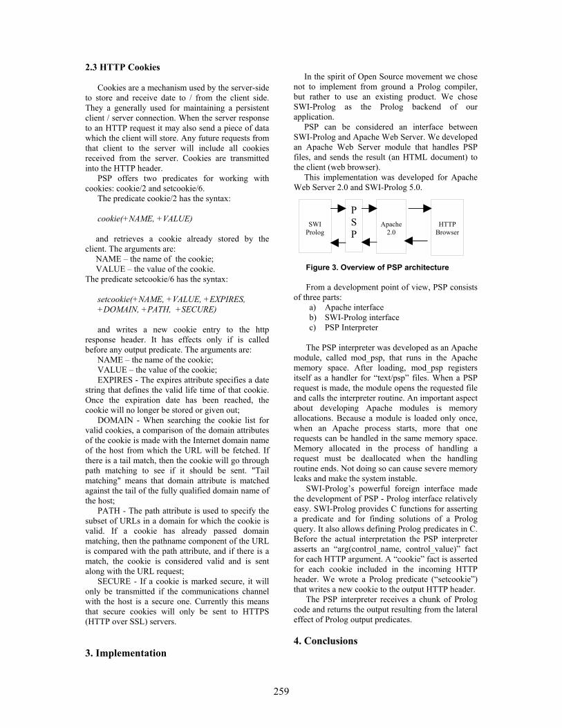
259
2.3 HTTP Cookies
Cookies are a mechanism used by the server-side to store and receive date to / from the client side. They a generally used for maintaining a persistent client / server connection. When the server response to an HTTP request it may also send a piece of data which the client will store. Any future requests from that client to the server will include all cookies received from the server. Cookies are transmitted into the HTTP header.
PSP offers two predicates for working with cookies: cookie/2 and setcookie/6.
The predicate cookie/2 has the syntax: cookie(+NAME, +VALUE) and retrieves a cookie already stored by the
client. The arguments are: NAME – the name of the cookie; VALUE – the value of the cookie.
The predicate setcookie/6 has the syntax:
setcookie(+NAME, +VALUE, +EXPIRES, +DOMAIN, +PATH, +SECURE) and writes a new cookie entry to the http
response header. It has effects only if is called before any output predicate. The arguments are:
NAME – the name of the cookie; VALUE – the value of the cookie; EXPIRES - The expires attribute specifies a date
string that defines the valid life time of that cookie. Once the expiration date has been reached, the cookie will no longer be stored or given out;
DOMAIN - When searching the cookie list for valid cookies, a comparison of the domain attributes of the cookie is made with the Internet domain name of the host from which the URL will be fetched. If there is a tail match, then the cookie will go through path matching to see if it should be sent. "Tail matching" means that domain attribute is matched against the tail of the fully qualified domain name of the host;
PATH - The path attribute is used to specify the subset of URLs in a domain for which the cookie is valid. If a cookie has already passed domain matching, then the pathname component of the URL is compared with the path attribute, and if there is a match, the cookie is considered valid and is sent along with the URL request;
SECURE - If a cookie is marked secure, it will only be transmitted if the communications channel with the host is a secure one. Currently this means that secure cookies will only be sent to HTTPS (HTTP over SSL) servers.
3. Implementation
In the spirit of Open Source movement we chose
not to implement from ground a Prolog compiler, but rather to use an existing product. We chose SWI-Prolog as the Prolog backend of our application.
PSP can be considered an interface between SWI-Prolog and Apache Web Server. We developed an Apache Web Server module that handles PSP files, and sends the result (an HTML document) to the client (web browser).
This implementation was developed for Apache Web Server 2.0 and SWI-Prolog 5.0.
Figure 3. Overview of PSP architecture
From a development point of view, PSP consists of three parts:
a) Apache interface b) SWI-Prolog interface c) PSP Interpreter
The PSP interpreter was developed as an Apache
module, called mod_psp, that runs in the Apache memory space. After loading, mod_psp registers itself as a handler for “text/psp” files. When a PSP request is made, the module opens the requested file and calls the interpreter routine. An important aspect about developing Apache modules is memory allocations. Because a module is loaded only once, when an Apache process starts, more that one requests can be handled in the same memory space. Memory allocated in the process of handling a request must be deallocated when the handling routine ends. Not doing so can cause severe memory leaks and make the system instable.
SWI-Prolog’s powerful foreign interface made the development of PSP - Prolog interface relatively easy. SWI-Prolog provides C functions for asserting a predicate and for finding solutions of a Prolog query. It also allows defining Prolog predicates in C. Before the actual interpretation the PSP interpreter asserts an “arg(control_name, control_value)” fact for each HTTP argument. A “cookie” fact is asserted for each cookie included in the incoming HTTP header. We wrote a Prolog predicate (“setcookie”) that writes a new cookie to the output HTTP header.
The PSP interpreter receives a chunk of Prolog code and returns the output resulting from the lateral effect of Prolog output predicates.
4. Conclusions
SWI Prolog
Apache 2.0
PSP
HTTP Browser

260
We developed an interface between SWI-Prolog, a robust Prolog implementation, and Apache HTTP Server, the most popular web server on the Internet.
PSP allows Prolog programmers to develop powerful web applications taking advantage of the advanced reasoning capabilities of Prolog.
PSP is intended to be an alternative to ASP and JSP for Prolog programmers as well as a complement to these technologies.
Thus, wherever Prolog seems more suitable for solving a specific task, PSP can be used together with other technologies (e.g. ASP, JSP). References [1] Bratko I., Prolog Programming for Artificial Intelligence, Addison-Wesley, 2001.
[2] Cabeza D., Hermenegildo M., Varma S., "The PiLLoW/CIAO Library for INTERNET/WWW Programming using Computational Logic Systems", In Proceedings of the 1st Workshop on Logic Programming Tools for INTERNET Applications, JICSLP'96, Bonn, September 1996, pp 72--90. [3] Developer Documentation for Apache 2.0 http://httpd.apache.org/docs-2.0/developer/ [4] Kristol D., Montulli L., HTTP State Management Mechanism, http://www.ietf.org/rfc/rfc2109.txt [5] Russell S., Norvig P., Artificial Intelligence – A Modern Approach, Prentice Hall, 1995. [6] SWI-Prolog Reference Manual, http://www.swi-prolog.org/

261
A Practical Solution to Detect DoS/DDoS Attacks
Manuel SUBREDU
Romanian Education Network
Iasi Branch [email protected]
Octavian RUSU
Romanian Education Network Iasi Branch
Valeriu VRACIU
Romanian Education Network Iasi Branch
Abstract In today’s networks one major problem, especially for Service Providers, is related to various attacks either active or passive. Denial of Services (DoS) is one of the most difficult to detect and stop. On the Internet DoS attack is an incident in which a user or an organization is deprivate of the services of a resource they would normally expect to have. DoS can be caused by a series of malicious activities. In this paper we will discuss a practical solution implemented by RoEduNet Iasi Branch, to detect and somehow stop the attacks from their beginning, using information provided by Cisco Netflow. This solution is implemented using C language, GNU/Linux [6], [7] as operating system and MySQL or PostgreSQL as database back-end.
1. Background
Denial of Service (DoS) and its derivative,
Distributed Denial of Service (DDoS) are some of the most common attacks. There are many types of DoS: Buffer Overflow, SYN attacks, teardrop attack, smurf attack, viruses or even physical infrastructure attacks [4]. Their intended goal is to disrupt the normal operation of networks and their main components: network equipment and computers connected to them. One of the most common kinds of DoS attack is to send on a network more traffic than in normal operation of that network is expected.
DoS/DDoS attacks are different and relative to the destination. For example, if we have a 128 kbps leased line, ICMP traffic of 128 kbps could be a DoS attack or the beginning of a DoS attack, but for an E1 connection, ICMP traffic of 128 kbps might not be an attack.
For Internet Service Providers (ISP) only massive DoS/DDoS attacks are easily detectable, because these slow down the network and even can lead to major network outages, mainly caused by disruption of normal operation of routers.
Usually, the source of DoS/DDoS attacks is unknown to the target, since most of these attacks are using random source IP addresses (spoofed IP addresses). To detect the real source of these attacks is a real challenge. In order to find the real source of attack, all the entities placed along the path from source to the target must cooperate in real time.
When an attack is detected (using custom methods) there are several practical options to consider:
• Filter the source IP address; • Filter the destination IP address; • Traffic shaping.
Filter the source address should be the best option, source being filtered; all packets received from the possibly attacking source IP address are discarded by the router. Unfortunately, this measure can be overtaken by the attacker using fake source IP addresses in constructing IP packets. As a result, filtering mechanism becomes useless. There is another even worse scenario: the attacker use multiple random source IP addresses. If filtering the source address is the method, then filtering engine must stop traffic from a lot of addresses. Shortly, the border router will filter more and more addresses leading to a series of consequences like: CPU load will increase and network performances will decrease and many IP addresses become unavailable.
This method can be used and it is the best option only if the source of the attack is well known and the attacker does not use IP address spoofing.
The second method, filtering the destination address, is a better option when attacker uses IP address spoofing but the destination will be filtered and, of course, the network services will be unavailable for the target of the attack. This solves the problem of the network service provider, but somehow the attacker’s objective is also accomplished.
In certain conditions this method is the only one to be considered. Access to the network

262
services for filtered destination IP can be offered using traffic rerouting, proxies, NAT, etc. After a time period the filters may be removed and normal services resumed. During this period it is likely that the offending source will cease the attack, because from its point of view the goal was accomplished.
The last option can be used in special circumstances, considering that traffic shaping procedures are CPU intensive processes, and do not give to the attacker the impression that his goal was achieved.
In this paper we discuss a practical solution implemented using a set of software tools at RoEduNet Iasi Branch, to detect and somehow stop the DoS/DDoS attacks from/to our network. The solution has been named zazu after a cartoon character and is available under the terms of GPL ([7]).
DoS/DDOS attack detection is based on information about the traffic through the routers. In network operations centers (NOCs) with high speed backbones, real time traffic dumps and traffic analysis is prohibitive because of huge amounts of data which passes through them. A solution for traffic analysis is provided for routers and some other networking equipment by traffic flow. On Cisco routers NetFlow provides such information. NetFlow data can be used for a variety of purposes, including network management and planning, enterprise accounting and departmental charge backs, ISP billing, data warehousing, and data mining for marketing purposes.
NetFlow technology provides IP flow information e.g. details about IP source and destination addresses, packet and byte counts, timestamps, Type of Service (ToS), application ports, next-hop address, input and output interface, etc. [2].
This information can be used to implement traffic accounting, detect patterns in Internet traffic, etc.
A flow is identified as a unidirectional stream of packets between a given source and destination - both defined by a network-layer IP address and transport-layer source and destination port numbers. Multiple flows are contained in a NetFlow exported UDP datagram. [2]
A flow is identified as the combination of the following seven key fields: [2]
• Source IP address • Destination IP address • Source port number • Destination port number • Layer 3 protocol type
• ToS byte •Input logical interface (ifIndex) NetFlow data is exported in UDP datagrams
in different formats identified by a version number [2].
In all versions, the datagram consists of a header and one or more records. NetFlow version is inserted in the first field of exported datagram. 2. Practical solution – Zazu software
In this paper a software platform used to analyze exported traffic flow from Cisco routers, detect various DoS/DDoS attacks and, eventually, take some action to stop the attack is presented.
The program is written in C, and has been tested on Linux. It has a modular design to accommodate multiple attack detection engines, uses a database to store all events and corresponding action and has a web interface for fast access to reports.
2.1. Zazu architecture
The architecture of zazu, presented in Figure 1, is based on the following components:
• FlowCapture Engine ; • Plugin manager; • Detection plugins; • Filtering Engine; • Alert and Report Engine; Flow capture Engine is implemented as a
daemon, listening on port UDP 2055. Flows are exported by FlowExport Entity which, in our particular case is a Cisco router. Other routers can export flows as well.
FlowCapture Engine receive multiple datagrams, convert information to a convenient format. To reduce the risk of receiving flows and/or information from routers which are not monitorized, before decoding the IP address of the exporting entity is checked against a list of known NetFlow export entities.
Due to the fact that multiple flows are contained within each NetFlow datagram, the FlowCapture Engine is decoding each flow from the datagram. The decoded flow is then converted to local format, and passed to Plugin Manager.
The Plugin manager analyze the flow received from the FlowCapture Engine, and passes the flows, in local format, to all installed plugins running at the time of detection.
A plugin is a separate module that is able to communicate with plugin manager, analyze the flow and return a standard response to Filtering Engine.
The plugin output is interpreted by the
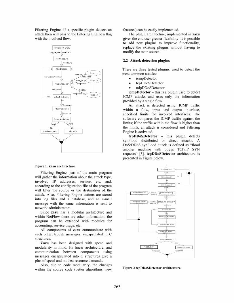
263
Filtering Engine. If a specific plugin detects an attack then will pass to the Filtering Engine a flag with the involved flow.
Figure 1. Zazu architecture.
Filtering Engine, part of the main program will gather the information about the attack type, involved IP addresses, service, etc. and, according to the configuration file of the program will filter the source or the destination of the attack. Also, Filtering Engine actions are stored into log files and a database, and an e-mail message with the same information is sent to network administrators.
Since zazu has a modular architecture and within NetFlow there are other information, the program can be extended with modules for accounting, service usage, etc.
All components of zazu communicate with each other, trough messages, encapsulated in C structures.
Zazu has been designed with speed and modularity in mind. Its linear architecture, and communication between components using messages encapsulated into C structures give a plus of speed and modest resource demands.
Also, due to code modularity, the changes within the source code (better algorithms, new
features) can be easily implemented. The plugin architecture, implemented in zazu
gives the end user greater flexibility. It is possible to add new plugins to improve functionality, replace the existing plugins without having to modify the main source.
2.2 Attack detection plugins
There are three tested plugins, used to detect the most common attacks:
• icmpDetector • tcpDDoSDetector • udpDDoSDetector icmpDetector – this is a plugin used to detect
ICMP attacks and uses only the information provided by a single flow.
An attack is detected using: ICMP traffic within a flow, input and output interface, specified limits for involved interfaces. The software compares the ICMP traffic against the limits; if the traffic within the flow is higher than the limits, an attack is considered and Filtering Engine is activated.
tcpDDoSDetector – this plugin detects synFlood distributed or direct attacks. A DoS/DDoS synFlood attack is defined as “flood another machine with bogus TCP/IP SYN requests” [3]. tcpDDoSDetector architecture is presented in Figure below.
Figure 2 tcpDDoSDetector architecture.

264
The target of a synFlood attack is quickly exhausting its computing resources trying to handle all the incoming connections, leading to unpredictable consequences.
For synFlood attacks detection, multiple flows must be checked. The tcpDDoSDetector plugin maintains a cache of those flows that have the SYN flag set. Before a new entry in the cache is created, a previous flow entry with the same characteristics is searched. If a match is found, a counter is incremented by 1. If no match is found a new entry is created. Since the cache size is limited, the entries are discarded using FILO (First In Last Out) method with timestamps. With each new flow added into cache, an analysis of the cache is performed in order to find synFlood attack signatures.
udpDDoSDetector – this plugin detects the
udpFlood distributed or direct attacks; it uses 2 methods: a. the one implemented in icmpDetector plugin
(instead of ICMP protocol related flows, the UDP protocol related flows are checked);
b. the one implemented in tcpDDoSDetector plugin, with some modifications:
• the size of cache is greater; • only the flows related to UDP
protocol are cached;
2.3. Other plugins Since information provided by NetFlow is
valuable, purposes other than attack detection can be achieved using NetFlow information.
dccSpy – this plugin is used to detect
connections to Direct Connect servers [5]. The algorithm used by this plugin checks every TCP flow with the SYN flag set. If the destination IP address and destination port are found in the list of known Direct Connect servers, the event is logged into a log file;
flowPrint – this plugin is used to print those
flows that match a given source and/or destination IP address. When a flow matches some or all of the given conditions, it is stored into a log file. This plugin is for testing purposes only.
fileFlowPrint – used to dump all the received
flows into plain text files for further analysis; it has the ability to create a new flow dump file at a given (configurable) period of time.
3. Conclusions and Future plans
This paper presents a practical software
solution to counteract against several types of network attacks, such as DoS and DDoS. The software (named zazu, after a cartoon character) is available under the terms of GPL and is successfully used at RoEduNet Iasi to defend various types of attacks against academic networks connected to our NOC.
Zazu's characteristics are: • performance:
o quick response to attacks using filtering methods;
o the resources required are modest (can run on a modest server: Intel CPU at least at 500Mhz, and 128MB RAM);
• features: o almost every parameter used
can be specified in the configuration file;
o MySQL and PostgreSQL support;
o E-mail alerts support; o log files support; o modular architecture; o reports via web interface;
• security: o configurable list of skipped IP
addresses for filtering; In the future, algorithms used in zazu will be
improved, and new attack detection plugins will be implemented. Some of the new planned features are:
• scripting support on the filtering engine; • better plugins integration; • support for more types of SQL servers; • improved web interface;
References: [1] An Adaptable Inter-Domain
Infrastructure Against DoS Attacks (http://www.netmode.ntua.gr/~gkoutep/docs/SSGRR03w_Koutepas.pdf)
[2] http://www.cisco.com [3] http://www.dict.org [4] http://www.webopedia.com [5] http://www.neo-modus.com [6] http://www.linux.org [7] http://www.gnu.org

265
Anatomy and Types of Attacks against
Computer Networks
Ass. Prof. Ion Tutănescu, Ph.D. Prof. Emil Sofron, Ph.D. Department of Electronics and Computers, University of Piteşti, ROMANIA
Abstract
The computer networks are based on free circulation of the information; they are built so to facilitate the users' access and to be very wide open to the information process. These facts make them vulnerable to the intruders' attacks. Once the local area networks get connected to Internet, the attack number and strength grows very much. All the attacks exploit the network security breaches.
In this paper we intend to present some of the passive and active attacks against the computer networks. Also we present the attack's anatomy, meaning the phases of the attacks and the techniques that are used in order to penetrate a network. Our purpose is to stress the several dangers the network administrators face and the necessity of setting a proper network security policy. The problem of attack detection is difficult because the detection technology is at beginning. Many times, when the attack is detected, the hacker remains unknown. After detection, the analyst needs some time to establish the attack nature.
1. Introduction
The needs of communication among the computers of different institutions, firms and organizations are in a continuous growth. The computer networks' number grows day by day and they interconnect among them or to Internet, resulting complex, wide area networks. More and more important sectors (energetic system, gas distribution system, transports, financial institutions, national security institutions and others) are based on computer networks' interconnection.
Once with the networks' connection to Internet or to other external computer networks, the aggression risks grow very much. The Internet evolution is and is estimated to be very fast. The Internet exposes the connected computers to attacks and the subsequent losses are in rise. Each network has its own risks, but the Internet-connected networks are more exposed in comparison with the networks without exterior access.
The ideal solution would be the network's physical separation by other extern networks, but the
interconnection needs make this unsuitable. The different compartments need to communicate one with the other and there is a real necessity of information, therefore to be connected to Internet. For this reason, new protection solutions are searched for assuring the security of the own computer networks, keeping in the same time the interconnection with the extern networks (Internet).
In this paper we approach a part of the aspects of this very complex problem. We refer to the aggressions against the computer and computer networks connected to the Internet or to other extern computer networks. We refer these aggressions as attacks. Also, we present some symptoms of the attacked networks and some measures one can take in order to protect the computer networks and the transmitted data.
2. Types of attacks
The computer networks are based on free
circulation of the information. They are built so to facilitate the users' access and to be very wide open to the information process. These facts make them vulnerable to the intruders' attacks. In future the networks should be accessible, too, but in the acceptable range of security assurance.
The potential threats to network security are: disasters, hardware faults, human errors and frauds. The first three are accidental threats while the last is a deliberate one. The computer security studies estimate that 50 % of total costs are determined by frauds and 25 % by human errors. These could be avoided through a better use of security procedures (periodical data backups, mirroring disks, limitation of access rights).
Once the local area networks get connected to Internet, the attack number and strength grows a lot. The connection to Internet is a necessity and opens wide windows for information and communication. But, the Internet is populated with individuals, groups, even powerful organizations which, for pleasure or with aggressive goals and intentions, exploit the breaches in the network security. The persons, who deliberately (having the aggressive goals to destroy, mislead, spy, etc.) or wishing to display their skills, transfer private information or steal/destroy the computer network data are named

266
hackers. The hackers are in several cases good programmers, who know and exploit the security breaches.
The singular attempt to get the unauthorised access in a computer or in a computer network is named attack.
The incident consists of a group of attacks, which are characterised by other attacks through the
existence of specific aggressors and attacked locations, the used techniques and the aggressions' synchronisation.
There are two main categories of attacks: passive attacks (data interception) and active attacks (data flow interruption, data modification and disinformation) as shown in Fig. 1.
Source
Destination
(a) Normal flow
(c) Interception (b) Interruption
(e) Disinformation (d) Modification
Fig. 1: Passive (c) and active attacks (b, d, e).
a. The passive attacks are characterised by: • they violate the confidentiality rules; • they do not generate damages (do not delete
or modify the data); • transmitted data are intercepted using
tapping wires, electromagnetic radiation interception, etc.
b. The active attacks are more dangerous,
because they modify the status of data, computers or communication systems. There are the following main types of active attacks:
• Interruption – uses the replay of a message or of a part of a message in order to produce an unauthorised access. For example, the authentication information of a previously sent Interruption often means the denial of service, when a system can not do its function because of the attacks (flooding with data packets).
• Modification - represents an attack that modifies (through insertion and/or deletion of characters) a part or all transmitted data.
• Disinformation – represents a type of attack where an unauthorised user pretends that is
an authorised user. For example, an user tries to substitute another user with the intention to get secret data. A disinformation is accompanied, as a rule, by another active attack as modification or interruption.
The most frequent attacks from Internet against
the networks are: 1) Password attacks. The password attacks are
used by hackers for the on-line networks. They use programs that automatically test the password, trying step by step each word from dictionary, until they find the used password. For this reason, this attack is named "dictionary-based attack".
2) IP sniffing. The hackers use a packet sniffer
which records the Internet data packets. Among these packets there are those with logging messages, e-mail, etc. So, the hackers could determine the accessed computer name, the user name, his password, the content of e-mail messages.
3) Trusted access attacks. These attacks
frequently act in Unix and Windows NT networks,
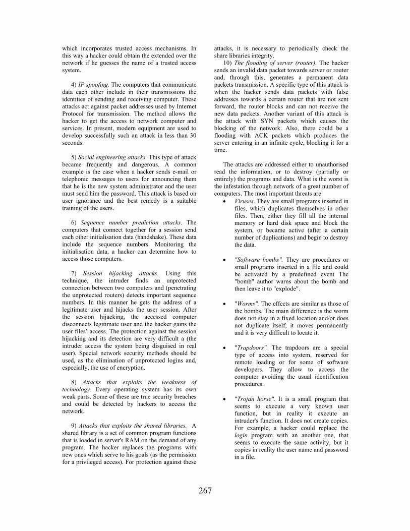
267
which incorporates trusted access mechanisms. In this way a hacker could obtain the extended over the network if he guesses the name of a trusted access system.
4) IP spoofing. The computers that communicate
data each other include in their transmissions the identities of sending and receiving computer. These attacks act against packet addresses used by Internet Protocol for transmission. The method allows the hacker to get the access to network computer and services. In present, modern equipment are used to develop successfully such an attack in less than 30 seconds.
5) Social engineering attacks. This type of attack
became frequently and dangerous. A common example is the case when a hacker sends e-mail or telephonic messages to users for announcing them that he is the new system administrator and the user must send him the password. This attack is based on user ignorance and the best remedy is a suitable training of the users.
6) Sequence number prediction attacks. The
computers that connect together for a session send each other initialisation data (handshake). These data include the sequence numbers. Monitoring the initialisation data, a hacker can determine how to access those computers.
7) Session hijacking attacks. Using this
technique, the intruder finds an unprotected connection between two computers and (penetrating the unprotected routers) detects important sequence numbers. In this manner he gets the address of a legitimate user and hijacks the user session. After the session hijacking, the accessed computer disconnects legitimate user and the hacker gains the user files’ access. The protection against the session hijacking and its detection are very difficult a (the intruder access the system being disguised in real user). Special network security methods should be used, as the elimination of unprotected logins and, especially, the use of encryption.
8) Attacks that exploits the weakness of
technology. Every operating system has its own weak parts. Some of these are true security breaches and could be detected by hackers to access the network.
9) Attacks that exploits the shared libraries. A
shared library is a set of common program functions that is loaded in server's RAM on the demand of any program. The hacker replaces the programs with new ones which serve to his goals (as the permission for a privileged access). For protection against these
attacks, it is necessary to periodically check the share libraries integrity.
10) The flooding of server (router). The hacker sends an invalid data packet towards server or router and, through this, generates a permanent data packets transmission. A specific type of this attack is when the hacker sends data packets with false addresses towards a certain router that are not sent forward, the router blocks and can not receive the new data packets. Another variant of this attack is the attack with SYN packets which causes the blocking of the network. Also, there could be a flooding with ACK packets which produces the server entering in an infinite cycle, blocking it for a time.
The attacks are addressed either to unauthorised
read the information, or to destroy (partially or entirely) the programs and data. What is the worst is the infestation through network of a great number of computers. The most important threats are:
• Viruses. They are small programs inserted in files, which duplicates themselves in other files. Then, either they fill all the internal memory or hard disk space and block the system, or became active (after a certain number of duplications) and begin to destroy the data.
• "Software bombs". They are procedures or
small programs inserted in a file and could be activated by a predefined event The "bomb" author warns about the bomb and then leave it to "explode".
• "Worms". The effects are similar as those of
the bombs. The main difference is the worm does not stay in a fixed location and/or does not duplicate itself; it moves permanently and it is very difficult to locate it.
• "Trapdoors". The trapdoors are a special
type of access into system, reserved for remote loading or for some of software developers. They allow to access the computer avoiding the usual identification procedures.
• "Trojan horse". It is a small program that
seems to execute a very known user function, but in reality it execute an intruder's function. It does not create copies. For example, a hacker could replace the login program with an another one, that seems to execute the same activity, but it copies in reality the user name and password in a file.

268
3. Anatomy of an Attack In Table 1 we present in a synthetic manner the
anatomy of an attack (phases of attack, targeted objectives and used techniques).
The attack techniques are in a continuous
development and refinement.
Table 1: Anatomy of an Attack
Phase of attack
Objective Technique
Footprint Target address range and naming
acquisition and information gathering are essential to a "surgical" attack; the key here is not to miss any details.
Search engines, WHOIS database, Web interface to WHOIS, DNS zone transfer.
Scanning Target address range, naming acquisition and information gathering are essential to a surgical attack. It is very important not to miss any details.
Ping sweep, Port scan.
Enumeration Bulk target assessment and identification of listening services focusing on the most promising avenues of entry.
List user accounts, List file shares, Identify applications.
Gaining Access
Enough data has been gathered at this point to make an informed attempt to access the target
Password eavesdropping, File share brute forcing, Password file grabbing, Buffer overflows.
Escalating Privilege
If only user level access was gained in the last step, the attacker will now seek to gain complete control of the system.
Password cracking, Known exploits.
Acquisition The information-gathering process begins again to identify mechanisms to gain access to trusted systems.
Evaluate trusts, Search for passwords.
Cover Tracks
Once total ownership of the target is secured, hiding this fact from the system administrators becomes paramount.
Clearing log files, Hiding tools.
Back Doors Trapdoors will be laid in various parts of the system to ensure that privileged access is easily regained at the whim of the intruder.
Create rogue user accounts, Schedule batch jobs, Infect startup files, Plant remote control services, Install monitoring mechanisms, Replace apps with trojans.
4. Detection of attacks
4.1. Symptoms of network's aggressions
The problem of attack detection is difficult. The detection technology is at beginning. Many times, when the attack is detected, the hacker remains unknown. After detection, the analyst needs some time to establish the attack nature.

269
Some of the following actions could be considered as symptoms of network's aggression:
• unexplained poor system performance or system crashes.
• new user accounts or high activity on a previously low usage account.
• new files (usually with novel or strange file names, such as data.xx or k or .xx).
• accounting discrepancies. • changes in file lengths or dates (especially
the grown of executable files). • attempts to write to system. • data modification or deletion (files start to
disappear). • denial of service and anomalies (frequent
unexplained "beeps"). • suspicious probes (there are numerous
unsuccessful login attempts from another node) or suspicious browsing.
4.2. Detection methods
If we previously mentioned the most frequent
attacks against the computer networks, we try now to give some detection methods for some of these attacks. Some methods for detecting the hacker attacks are:
a) IP sniffing. For detection are used identification schemes with one-time passwords or token authentication systems, simultaneously with the opening of a logfile.
b) IP spoofing. For its detection is necessary to check the network input traffic which pass the router. It is used for this a system log that records all the source and destination addresses. The messages with internal source and destination addresses must not enter in the network. The presence of such messages is a clear indication about an IP spoofing.
c) Sequence number prediction attacks. They could be detected through the implementation on server (router, firewall if the case) of audit trails. Audit trails determine the displaying of warning messages when the hacker tries to find the sequence numbers. Using the operation system event logger, could be realized an automated alarm after a certain number of successive denials of access.
d) Session hijacking attacks. In this case, it could be noticed an unusual activity (the displaying of the hacker keystrokes on the screen, the connection loosing). The user must report immediately these suspect activities.
e) Attacks that exploits the shared libraries. For detecting these attacks it is necessary to periodically check the shared libraries integrity.
f) The flooding of server (router).This type of attack can be detected through the countering of ACK/SYN packet numbers and their relating to the total data packet number. Normally, this ratio is 1/3 ÷ 1/2. If the ratio grows very much (during an attack this ratio could reach 300/1) the aggression is detected and protection methods are necessary. 4.3. Digital signatures
A very good solution for detecting the attacks is
the use of digital signatures, too. The digital signatures confirm the user identity and, moreover, the fact that the files were not altered during the transmission.
The DSA (Digital Signature Algorithm)
algorithm for digitally signing a message uses the following global parameters:
p - a prime number (512 bits), q - a prime divisor of p-1 (160 bits), g - an integer with the property: g = h(p-1)/q mod(p), where h is an integer, so as h(p-1)/q mod(p) > 1 and H - a hash function. The user parameters are: x - an integer (the secret key) and y=gx mod (p) - an integer. a. To digitally sign with the signature (r,s) a
message M: • An integer k, prime with q, is chosen in the
range (0, q). • Then r and s are calculated: r = (gk mod(p)) mod(q); s = ((k-1)(H(M)+xr)) mod(q). b. To check the digital signature of a message is
calculated w: w = s - 1 mod(q), where s should be reversible. The digital signature is valid if:
r = (gH(M)w yrw mod(p)) mod(q) .
5. Conclusions
In this paper we want to refer to hacker attacks against computer networks. Once the local area networks get connected to Internet, the attack

270
number and strength grows very much. All the attacks exploit the network security breaches. For this reason is necessary a network security policy.
The network security is very complex, difficult to be designed and - more then all - difficult to be assured. It is easier to prove that a network can be
penetrated, than to prove that it is completely sure. Security system is expensive and introduces unpleasant user limitations. The security system does not grow the network performance, but the threats are real and the risk is too big without a proper security policy.
6. References:
[1.] CERT - "Annual Report", 1996, 1997, 1998, 1999, 2000, 2001; [2.] Cronin D.J- “Microcomputer Data Security”, Prentice Hall Press, New York; [3.] Klander L. - “Anti Hacker”, Jamsa Press, 1997; [4.] Fraser B. - “Site Security Handbook”, 1997; [5.] Libicki M. - “What is Information Warfare?”, National Defense University Press, 1995;
[6.] Sullivan G.R– “War in the Information Age”, Military Review, April 1994, pp. 46-62; [7.] White G.B., Fish E.A., Pooch E.W.- “Computers System and Network Security”, 1996; [8.] Patriciu V.V., Pietroşanu-Ene M., Bica I., Cristea C. - “Securitatea informatică în UNIX şi INTERNET” (“Information Security in UNIX and INTERNET”), Editura Tehnică, Bucureşti, 1998.

271
Reflective Blended Methods for Teaching and Learning Operating Systems
Monica Vladoiu Catalina Negoita Petroleum-Gas University of Ploiesti, Romania Petroleum-Gas University of Ploiesti, Romania
[email protected] [email protected]
Abstract
Traditional university world with both faculty and students enjoying the intellectual challenge of knowledge mastering is not a reality anymore. Nowadays students juggle their university studies together with parallel studies of other subject, paid employment or other activities. In order to keep them close to the knowledge world, educators have to devise new attractive ways for reflective learning. Blended learning seems to be a natural evolution for our instruction agenda. It represents an opportunity to integrate the best traditional instruction with e-learning. We present here our current solution, constructivist and collaborative, for a reflective blended teaching and learning environment around Operating Systems subject, that is a combination of an open engagement for lectures with working action project-based groups for laboratories, and an integrated e-learning hypermedia application. 1. Introduction
Traditional university world with both faculty and students enjoying the intellectual challenge of knowledge mastering is not a reality anymore. The pressure of the quickly changing reality has strongly affected this model. Nowadays students juggle their university studies together with parallel studies of other subject, paid employment or other activities [4, 11]. In order to keep them close to the knowledge world, the only known way to a sound personal evolution, educators have to devise new attractive ways for reflective teaching and learning (TL). Reflection can be seen both as a process by which an experience (thought, feeling, action) is brought into consideration (in- and following-action) and as a way to create meaning and conceptualization from that experience and to look back at it from another perspective (critical reflection), independently or in a social context.
Blended learning seems to be a natural evolution for our instructional agenda. It represents an opportunity to integrate the innovative pedagogical
and technological advances with vibrant interaction and collaboration offered by the best traditional instruction. Blended learning needs enthusiasm, energy and commitment to make a difference towards reflection in an instructional environment.
E-learning has had an interesting impact on the learning environment. Although it has a huge potential for revolutionizing teaching and learning, it has rapidly attached to the concept of blended learning, which mix online learning with traditional methods for instruction [7, 13].
At the core of the e-learning context is a collaborative constructive transaction. E-learning is exciting from this perspective, because it enhances and enriches both the content and the context. The challenge is to design and create a context around it, with appropriate level of social presence, which provide for congruency with the instructional goals and for enhancement of learning outcomes [4].
Teaching Operating Systems, with the complex world of data structures and algorithms inside it, is not a straightforward process, as students do not usually have a natural perception of a computer essentially extended with the operating system, as an ontological accessible reality. Few years before when we started to lecture this subject for the students from two specializations in our university (Automatics, Mathematics-Informatics) we have realized that the traditional way of teaching and learning will just do not work. As hybrid (blended) models, including both online and face-to-face teaching and learning were becoming a de facto solution [4, 6, 7, 12, 13] we have thought to start developing such a teaching and learning experience.
We present here our current solution, constructivist and collaborative, for a reflective blended TL environment around Operating Systems subject, that is a combination of an open engagement for lectures with working action and project-based groups for laboratories (small 2-3 student groups), and an integrated e-learning hypermedia application.
The paper is organized as follows: Section 2 is a brief motivation for the need for reflection in TL process, Section 3 presents the open engagement model for lecture that we have been using, Section 4 introduces the reflective laboratory work that we

272
have developed, Section 5 describes the modality in which we have been doing assessment of learning and of the TL process, and, finally, the last section presents some results, conclusions and future work.
2. Need for reflection The dominant issue in education today is not
access to more information. In fact, making sense of the amount of material they are exposed to is a serious challenge for students. It is impossible to meaningfully assimilate all the relevant information in even narrowest of subject areas.
Because of this informational explosion and the amazing advances in ICT, new approaches are required and become possible. In order to have our students managing this overwhelming mass of information the only long-term solution seems to be the construction of an educational environment in which students will not only learn, but they will learn to learn and to reflect in their learning process into a social context [3, 4, 7, 11].
Upon reflection, it should be no surprise that most research into using technology for educational purposes has shown no significant differences in learning outcomes between traditional and technically advanced media [4, 7, 11]. This is true because we do essentially the same thing as always with respect to teaching and learning, except that the medium of communication has changed.
An educational experience has a dual purpose. The first one is to construct meaning (reconstruction of experience) from a personal perspective. The second is to refine and confirm this understanding collaboratively within a community of learners. These aims are interleaving each other within teaching and learning situations resulting in an educational process which is a unified transaction.
Educators must create cognitive and social conditions that will allow and encourage students to approach learning in a meaningful way. Of course this demands content expertise, but it is what the teacher does pedagogically that determines the degree to which students assume responsibility for their learning. Having the learner accepting this responsibility is a crucial step in realizing successful educational outcomes – both in term of specific functional knowledge structures and in terms of developing the higher-order cognitive abilities that are necessary for continuous learning [3, 4, 7, 11].
Reflection of a learner’s practice may take place within actions and following actions. The reflection-in-action can be a conversation with oneself during action and/or with others engaged in it through, but not necessarily via dialogue. It is possible to communicate also by non-verbal means. The opportunity and ability to reflect after an action is critical to the potentiality of future actions and events. The reflection-on-action which take place after the action is important with other(s) in dialogue
because the actor may not be able to see herself/himself but limitedly.
Under reflection perspective, the desired outcome of education becomes the construction of coherent functional knowledge structures adaptable to further lifelong learning.
3. Open-engagement model for lectures The key requirements for reflective practice are
dialogue, intention, process, modeling, and personal stance. Underlying the capacity for educators to engage in reflection with learners is the explicit recognition of the interaction as a relationship with learners. As a consequence, knowledge will come through mutual communication. Prior conditions for reflection require the educator to be aware of process, intentionality about it and the fact that s/he is modeling the process, as well as the appropriate form of dialogue. Personal stance is an important part of the process by which we all learn. How we place ourselves, within any instructional context, whether formal or informal, is fundamental [3, 10].
For acquiring reflective instruction educators and learners must engage and work together so that they jointly construct meaning and knowledge from the course material. The educator becomes a facilitator of learning and the focus is on students’ learning and how they may come to understand, appropriate, modify and transcend meanings with the content.
Traditional transmissional lectures are a good way to deliver content to a large number of learners cheaply, but they do not provide for reflective learning [2, 7, 11]. If lecturing is to be justified educationally, it must be done in terms of the one major advantage it has over all other methods of teaching: the unique experience of live, face-to-face contact with a large number of learners.
Being “live” provides a great opportunity for engagement and dialogue. Being “large” gives to the dialogue the potential for a tremendous sharing. These should not be underestimated or devalued. They create the premises for a broad mutual intellectual experience of “being where the action is”. A possible way to benefit from this view implies that traditional lectures need to be re-envisaged as a large-scale dialogue in which both lecturer and learners are being truly engaged [7].
The two models of lecturing can be summarized as in Table 1 [7]. The first model focuses on the content of the lecture almost exclusively, the lecturer being viewed as an instrument for transmitting information, while the second one focuses on the lecturer as a person committed to engaging with learners in a dialogue concerning particular material.
We have started by introducing an engaging lecture that has had its focus on the process by which the lecturer engaged learners in a reflective dialogue for communicating the knowledge. The main characteristics of this kind of lecture have been openness and friendliness to learners.

273
Transmission Engagement
Structure
information monologue linear transmit
understanding dialogue non-linear appropriate
Method
lecturer agenda transferring info surface lecturing lecture as truth get content “out”
learner agenda engaging minds deep lecturing lecture as narration get content “in”
Lecturer
head and body sober persona cognitive focus objective/subjective
head, body, self engaged persona interpersonal focus inter-subjective
Table 1. Two models of lecture
The content has been constructed together with the learners in a snowball fashion. We have been trying to help students make connections, challenge preconceptions, relate the content with concrete problems/real cases, and to critically analyze hypotheses and interpretations. Instead of being worried about passing to the learners huge amounts of information within the given syllabus, we have been concerned with helping the students to appropriate the content and to co-relate it with their previous similar practices and to their general real-world experience. Periodical few minutes periods out of the lecture flow have been used for reflection by means of:
• providing time for students to “digest” the content and to construct their own personal knowledge from it. This have been achieved usually by focusing around a specific question at a time (like ‘what real-world situation is synonym with this from the operating systems’);
• sharing ideas and difficult issues with their neighbors, which have resulted in inquiries for the lecturer and opportunities to re-iterate from another point of view those issues;
• working on some specific task (e.g. quick design sketch of an algorithm for best-fit partitioning, after they have been presented with the first-fit partitioning one).
Student interaction with the content takes usually place in an iterative process that includes the following steps: statement of objectives, exploration, experimentation, simulation and knowledge testing [6, 7]. We have been trying to shift the manner of approaching this, from the objectivist paradigm of teaching and learning (introduction, concept, example, practice, reflection) to the constructivist one (problem, background, concept, analysis, solution, reflection) by facilitating, rather then teaching the content.
What the facilitator does that is different from lecturing, supervising or leading seminar discussions? In fact the activities that s/he performs are mainly the same. What is different is her/his attitude towards them and to the learners. We can all remember at least one bored or haughty educator
who have replied in an un-facilitating manner to one of our questions (if we have dared to ask it, of course), while we have been students ourselves. A facilitator is supposed to be the total opposite of that. The personal presence and conduct, the working and interaction (e-)framework s/he provide, her/his non-verbal and verbal communications, the way s/he listens and responds empathically as well as accurately to the students are some of the means to be used to improve educator’s facilitative abilities, while performing usual TL transactions. 4. Reflective laboratory work
Research on teaching and learning generally shows that in order to have students understanding and applying what they learn, the learning experience should be collaborative, facilitate applying the new knowledge to various real-life scenarios, and deal with content applicable to students’ life and work situation. This can be accomplished with well-designed and constructed online material and collaboration tools for integrated learning experiences [6, 7, 11].
At the beginning, laboratory sessions were supported by a written material, which has been supposed to follow the student natural approach for learning a new operating system, Unix in this case. The material was designed to be easy to understand (with many examples intuitively explained), self-contained, supportive, and fun. Instructor role was only to assist the learners, to stimulate them to work together on common small-size projects, but also to compete with other teams, and to animate a reflective dialogue around the working issues and about their work as individuals and as teams.
S/he also have had to provide for openness and empathy between team members, for awareness and acceptance of diversity, for equal expression opportunities tailored to personal needs, both observed and explicitly expressed, and finally for constructive criticism.
During semester, the small teams have been kept in many cases the same, giving the possibility for the groups to act as action learning sets. According to our personal experience too, working together with your fellow students at common or similar projects can provide a not replaceable support [3, 4, 7, 11]. If the learner feels comfortably enough with her/his peers to share and reflect upon their existing knowledge, their relationship to particular situations that may be familiar or novel, and to context in which they are happening, the conditions for reflective dialogue and critically reflective learning are created. Thus a cycle of action, learning and reflection is built into the process, for every group member.
We have not neglected the fact that there are some students who prefer to work alone without being involved in group activities. Our strategy has

274
been to offer the best learning experience for every student. However, generally, our students have preferred to work in groups rather than alone, in spite of the fact that there were enough computers to have each student working by oneself. We think that has been happening because the action group learning is both supporting and challenging and we have been witnessing this ourselves and during the last years, as educators.
We can say that provided there are many well-articulated opportunities for interaction both between learners and with the instructor, it becomes possible to create vibrant interaction among the participants, at least from time to time.
Lately, with the amazing advancement of ICT, the next natural step was the use of computer-based learning in order to increase the opportunities for reflective learning. We have developed an integrated e-learning package that uses Macromedia and Java technologies. It incorporates operating systems’ knowledge with our ideas about reflective learning means and with the well-known advantages offered by well-done e-learning applications to students (anytime/anywhere/anyone access, pace/path/depth of learning suitable to learner needs, abilities and schedule, possibility of repeated e-experimentation and self-testing etc.). We present a sample screen of this application in Figure 1. It offers to students various possibilities from accessing the content of course and laboratory sessions, to various tests, interactive exercises, simulations, useful links, exam requirements or contact information.
A great advantage of using e-mediated content has been that it provides for having students’ practicing the concepts and techniques repeatedly, with instant visual or text-based computer generated feedback. The value of well-designed e-learning is also in its capacity to support reflective interaction, independent of the time pressure and of the distance constraints, and to facilitate communication and thinking and thereby to construct meaning and knowledge [4, 11]. Online content can go beyond what can be presented in a textbook or in the classroom: interactive exercises with computer-generated responses, graphical representations of various scenarios that immediately respond to student manipulation, threaded discussions where the conversations can be continued beyond class time etc. [6, 11, 13] 5. Evaluation
Assessing students is probably one of the most emotionally sensitive part of our instruction, being in the same time intellectually demanding. It can be also emotionally and socially disturbing and divisive for learners. Students need to feel that they have been given the best opportunity to express their ability in the discipline, but also to convey something of themselves on what the subject means
to them [3, 7]. Without this, evaluation is associated with a system of control and this can be disturbing for students and for the learning process.
In academic settings, assessment is often associated with grades, which offer very limited possibility for what students have learned. This form of assessment if often referred to as “norm-referenced” evaluation. The result here is not so much about what students achieve, but more about their position in relation to other students [4, 7]. Assessment that evaluate against sets of predetermined criteria (criterion-referenced) helps students to understand how their performance has progressed and educators to check the achievements of the instructional process.
The two main types of evaluation are formative and summative. Formative evaluation is an ongoing process that takes place throughout the whole course delivery, in order to fill gaps and to clarify and adjust the content and the delivery mechanisms. This kind of evaluation is crucial for exclusive e-learning transactions, since the non-verbal feedback easily picked up in a face-to-face setting is not available.
Summative evaluation, in form of a grade, takes place after the course. In order to assure the best possible assessment, multiple sources of information should be used [6, 7]: self-evaluations, quizzes, quality of projects, interaction and collaboration within lectures and practical work sessions, and, finally exam results.
Whether criterion or norm-based methods are used, the assessment of reflection, either formative or summative, will include a judgment about the outcome, namely the quality of learning which emerges. For instance, for our course, evidence of critically reflective learning will require students to have not only understood and appropriated the key aspects of Operating Systems, but also will reveal that they have begun to question the paradigmatic basis of the discipline itself, as well as some record of their reflective journey to that point. Thus, the grade indicates both the acquiring of knowledge and the reflection involved in the process. What cannot be recorded in such an assignment is the relationship which evolves between course material, learners, and educators.
If critically reflective learning has occurred then the first person to know about it is the learner. When one’s learning is communicated to others in writing or verbally, this is known as “self-report”. When others, possibly fellow students or tutor, report on their observations or experience of the learner, this is known as “other-report”. If one “other” is the tutor, then the well-known reliability of triangulation is achieved: self, other-student and other-tutor [3, 4].
To provide evidence of the learning relationship and the learning journey, “other-reports” are essential, therefore evidence from fellow-students is needed. This is not peer-assessment, because students do not evaluate each other, but they are a
275
source of information about the learning process revealed in reflective dialogue [3, 4].
To assess both the evidence of critically reflective learning, in terms of outcome within the subject discipline, as well as the process of the student’s reflection can be used the following strategy [3]:
• a way to identify critically reflective learning in terms of outcome within the subject discipline;
• a way to ascertain that reflective dialogue has taken place (at least personally, but ideally with others);
• a way to establish that there is evidence of the learner participation in that dialogue;
• a way to identify evidence of a developmental process over time;
• a way to make certain that there is evidence that a process review has taken place, enabling the student to take away some understanding of the learning process.
For the first step of the strategy we have been
using a combination of small size projects during laboratory work, timed quizzes, and special tasks to be solved during exam (involving critical thinking – as developing of algorithms for particular problems, other than the ones presented in the course, analyzing various strategies and choosing the best one for a specific situation etc.). In order to make students feel confident about their approach to the assessment we have been giving them the possibility to consult every material at their choice. We have eliminated this way the need for memorization as a goal in itself and have been trying to lead them to deeper forms of understanding and learning.
In approaching the other four steps, until now, we have been trying not to burden more our students with recording in writing their learning logs (which contain the description of their learning experience) or portfolios (that are compilations of learning intentions, accounts of learning activities, learning outcomes, and records of reflective dialogue). For the time being, all these are still at an informal level. Even so, we have got valuable feedback from our students and colleagues, and we have been improving our general strategy on-the-fly. Taking some time off from the course flow, regularly, to reflect together on the instruction process in which we have been equally engaged and responsible have proved to be very useful and valuable. 7. Results, conclusions and future work
The myth that higher education nowadays comprises a community of learners dedicated to achieving high-level learning outcomes is no more a reality. The assertion that communities of inquiry in higher education encourage students to approach
learning in a reflective, critical manner and process knowledge in a deep and meaningful way is rhetorical. Therefore educators have to devise appealing and efficient ways to instruct and educate their students. Integration of meaningful educational approaches with innovative technological enablers can be suitable for solving this problem. Blended learning solutions tailored to the specific communities of students can provide for this goal.
Students will not learn if educators fail to convince them that learning is important and related with their day-to-day life, to guide them according with their need and learning styles through the knowledge content, to relate the topic to be taught to their experiences and to motivate them by constructing the learning experiences around their natural motivations.
A blended learning experience demands the insight and agility of a reflective and knowledgeable teacher who can translate principles and guidelines to the contingencies and exigencies of their unique contexts [4, 7, 13]. The new e-learning paradigm move some of the power over content and delivery from the educator (who becomes a facilitator) to the learner and makes it possible to develop a sustainable and close-knit community of peer learners without ongoing face-to-face interaction [6]. Well-designed e-learning within blended learning solutions represents a unique opportunity to change the way we teach and learn [6, 11]. It makes possible to collaborate across time and space, giving educators a good chance to explore sound pedagogical principles (e.g. constructivism).
Results that we have obtained by now are encouraging and we are trying to enhance our courseware with other reflective opportunities as prior-notice exams, larger size/time projects to be tackled by 6-8 student groups during the whole semester and involvement of learners in marking process against a set of well-defined criteria.
We recognize that the move from teaching subject content or demonstrating an experiment to facilitating reflective dialogue with students is not straightforward. But we cannot simply recommend critically reflective and transformational learning to our students without aiming to be such learners ourselves, despite the fact that teaching is seen as a Cinderella in higher education nowadays, when research is taking all the credit.
The transition from transmitting content to attending to the learners’ needs is unfamiliar and can be difficult for both educators and learners. We have started with us engaging with each other in reflective dialogue by recourse to the course content and to our practice: teaching, scholarship, course leadership, instructional design and implementation, and research. This experience acted as a precursor to working as facilitators of reflective dialogue to student learners.

276
In the facilitator’s role is embodied knowledge, self and world, the three domains of expression, whereas, in traditional teaching, the practice emphasizes primarily one domain, that of knowledge. The three domains of knowledge, self (emotion) and world (inter-action) have been identified as necessary for the survival of higher level learning and the emancipatory endeavor of a university education [2, 3].
By focusing on the idea of reflective dialogue between educator, as facilitator and learners, we have been aiming to a basic form of an emerging relationship that can evolve to a framework for transformational learning. Critically transformative learning involves not only deconstructing meanings and the taken-for-granted attitudes, ways of seeing things, and myths, but also reconstructing by re-conceptualizing and rebuilding. This continuous process becomes the subject of further transformative learning. It is a restless, ever-changing process of evolution for the learner where the basis is laid in the experience of higher education for life [3].
As future work, we intend to develop a more structured and flexible e-communication framework including both synchronous (chat) and asynchronous possibilities (threaded discussions, collaborative e-exercises). A common misconception is that interaction in e-instruction is of lower quality that the one from regular classroom. Research shows that, due to various flexible (time/place independent) modes of interaction, this can be more rewarding, provided that it is properly handled [1, 4, 11, 13]. These enhancements depend on availability of resources being well known the fact that developing complex immersive e-learning applications is very costly both as time and of other resources.
We are also working to a more formal implementation of the assessment strategy for the reflective instruction cycle. Finally, we would like to analyze properly the outcomes of this blended learning solution and to prepare a methodology for reflective learning in science, having aid from specialists in education field. Of course, we do not forget that “nothing has brought pedagogical theory into greater disrepute than the belief that it is identified with handing out to teachers recipes and models to be followed in teaching” [5]. Effective teaching requires more than a repertoire of techniques. To make real a coherent interplay between the collaborative (social) and constructivist (cognitive) nature of proper teaching and learning it takes more than a methodology. It takes personal engagement from all the actors involved in instructional transaction.
Increasingly, higher education is returning to its roots by focusing on the values and practices associated with collaborative approaches to learning, and we include here the educator also. Along with this is the realization that constructing personal
meaning is enabled by opportunities to test one’s understanding in a social context and to apply new ideas and solutions in relevant contexts.
Blended learning represents an important opportunity for building a community of lifelong learners that keep them motivated and close to the knowledge world. Education is but an illusion if it simply disseminates information without actively supporting a critical assessment and the opportunity to provide meaningful knowledge functional structures that will serve for future learning challenges. As Dewey has said: “the result of the educative process is capacity for further education”. Acknowledgments I would like to thank to ERCIM (European Research Consortium for Informatics and Mathematics) for awarding me this post-doc fellowship and for the constant support I have got from the people there, especially Ms. Emma Liere. It is my biggest pleasure to thank to Prof. Ingeborg Sølvberg, my supervisor here at Dept. of Computer and Information Science, Norwegian University of Science and Technology (NTNU), for her kind support every step of the way, and to all the people from the department for hosting me and making me feeling home here.
8. References and bibliography [1] Allesi, S. M., Trollip, S.R., Multimedia for Learning. Methods and Development, Allyn and Bacon, Boston, 2001 [2] Barnett, R., Higher Education: A Critical Business, SRHE/Open University Press, Buckingham, 1997 [3] Brockbank, A., McGill, I., Facilitating Reflective Learning in Higher Education, SRHE/Open University Press Imprint, 1998 [4] Garisson, D. R., Anderson, T., E-Learning in the 21st Century, RoutledgeFalmer, London, 2003 [5] Dewey, J., Experience and education, Collier Macmillan, New York, 1938 [6] Engvig, M., ELearning in Academic Settings: A Short Introduction, Themo Publishing, Rissa, 2002 [7] Light G., Cox R., Learning and Teaching in Higher Education. The reflective professional, Paul Chapman Publishing, London, 2001 [8] Loughran, J.J., Developing reflective practice. Learning about Teaching and Learning through Modelling, Falmer Press, London, 1996 [9] Prensky, M., Digital Game-Based Learning, McGraw-Hill, New York, 2001 [10] Salmon, P., Personal stances in learning, in S. W. Weil and I.J. McGill (eds), Making Sense of Experiential Learning, SRHE/Open University Press Imprint, 1989 [11] Schank, R., Designing world-class e-learning. How IBM, GE, Harvard Business School and Columbia University are Succeeding at e-Learning, McGraw-Hill, New York, 2002 [12] Schunk, D.H., Zimmerman B.J., Self-regulated learning – from teaching to self-reflective practice, Guilford Press, New York, 1998 [13] Thorne, K., Blended learning – how to integrate online & traditional learning, Kogan Page Ltd, London, 2003
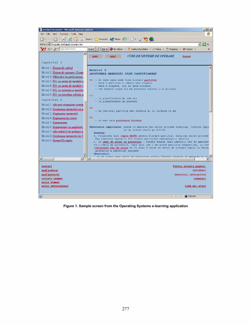
277
Figure 1. Sample screen from the Operating Systems e-learning application
278
LDAP-based DNS Management System
Djordje Vulovic, Dejan Brkic, Zoran Jovanovic University of Belgrade
Abstract
This paper addresses the problem of DNS server management process. Managing DNS data on Unix-based system using a BIND software package is most often done by editing ASCII files containing DNS zones, and then signaling the server process to reload them. This kind of management is error-prone, it requires accessing the server over the actual or virtual console, and it is not suitable for complex operations which require related changes in the several records or zones. The authors propose the distributed system for DNS zone management. DNS server data (primary zones and their resource records) are being stored in the LDAP-based directory. The DNS server uses LDAP protocol to access its primary zones data. DNS zones are managed by the Web-based application. The system has been implemented using BIND DNS server, openldap LDAP server and tomcat application server on the Linux operating system.
1 Background technology
In this chapter we will briefly describe two most important background technologies used in this management system: DNS and LDAP.
1.1 Domain Name System (DNS)
DNS system has been introduced to solve the problem of scalable and distributed name-to-address conversion. However, it has been designed as distributed Internet database, which can be used to store multiple types of data.
DNS uses a hierarchical namespace, as opposed to a flat namespace, used by previous technologies. The whole DNS namespace is divided into domains. Complete DNS name contains the local domain part and the name of the domain, and it is called fully qualified domain name (FQDN). Each name can have multiple associated data (i.e. IP address). This data is stored in the form of resource records. Collection of resource records for a domain is called zone of authority, or simply zone.
DNS service is client-server type of application. Server side comes in the form of DNS server
software. It has two main tasks: keeping the delegated zones, and resolving clients’ requests. Usually, a DNS server accomplishes both of these tasks, although there are applications in which DNS server does not store any zone (caching-only name server). Client side consists of the name resolver application, which queries the specified server for resource records. Usually, a server is responsible for contacting all the required DNS servers for obtaining the answer.
Every zone has to be stored in, at least, two DNS servers, called authoritative servers. One of these servers is denoted as the primary server and the others are considered as the secondary servers. Every zone change is applied on the primary server, and the secondary servers are responsible for periodically downloading zone data from the primary server.
DNS server has to be able to find specified resource record for any name in the DNS namespace. In order to fulfill this task, DNS server has to know the addresses of the servers keeping zone for the topmost domain (“.”).
There are many types of resource records. Each zone has only one SOA (Start of Authority) record, which defines various zones parameters as the name of the primary server, and the zone counter. Some of the most used resource records are:
NS record specifies all the authoritative name servers for the zone, and also name servers for the subdomain zone;
A record specifies IP address for the corresponding name;
CNAME record represents symbolic link to some other name;
PTR record specifies name that some IP address should convert to. This PTR records can be found only in the special zones called inverse-mapping zones. Names that can have PTR record have to be in the form of D.C.B.A.in-addr.arpa and it specifies the name that IP address A.B.C.D should convert to.
The DNS standard [1] describes the standard text representation of the zones and associated resource records. The most popular DNS software (e.g. BIND) keeps the zones as text files.

279
1.2 Lightweight Directory Access Protocol (LDAP)
LDAP is the Internet standard protocol for directory access. It is the successor of the DAP protocol.
Directory is hierarchical database with several distinguishing features:
read and search directory access is much more frequent than write access;
there is the standard LDAP protocol for directory access;
there are standard directory schemes describing format of the directory data.
Directory stores data in the forms of entries. Each entry has its own identification, called a distinguished name (DN). The distinguished name has a hierarchical form. Hierarchical tree of entries is called directory information tree (DIT).
An entry consists of attributes. Each attribute may have several values. Entry classes define attributes that must and may appear in the entry as well as formats of attribute values. The collection of related entry classes is called a directory scheme.
2 DNS server management
Management of the DNS server consists of several tasks:
adding a new zone (with the special case of adding a subdomain zone);
removing an existing zone; adding, changing and removing resource
records from a zone; changing server parameters.
Various DNS server implementations address these issues in a different manner. From now on, we will concentrate on the BIND 9.x server software package, which is, defacto, the standard on the various Unix-based systems, and, arguably, the most widespread DNS server software. BIND server keeps the configuration settings in one or more text files. These settings are grouped in the numerous categories [2]. The most important category is the zone category, which defines the primary and the secondary zones, as well as their parameters such as the name of the file storing the zone. After each configuration change, the server process has to be restarted.
Zone data are stored in the text files, referenced from the configuration settings. The zone management is most often accomplished by a simple text editor, although there are applications that provide some kind of user interface. After each zone change, server process has to be notified to reload the zone.
This kind of management has several drawbacks: Administrator has to have access to the
server, either by console, or with Telnet/SSH/X server.
Editing text files is error-prone Often, a complete action requires related
changes in two or more files. For example, adding new A record usually requires adding new PTR record in the inverse zone. Adding new zone requires o adding new zone information in
the configuration settings file; o creating new zone file with initial
SOA record; o adding NS records into parent
zone; o adding ‘glue’ A records in the
parent zone (optional). The whole management process is hard
to implement and, especially, maintain when a server keeps zones managed by different administrators. It is often unfeasible to create user accounts, and it is undesirable to let every administrator contact the server process.
3 Distributed management concept
In this paper we will present new DNS management concept. Its basic idea is to distribute responsibilities across several servers:
LDAP server keeps the primary zones data;
DNS server contacts the LDAP server for retrieval of the primary zones resource records;
Application server runs the Web-based management application, which directly edits zone data in the LDAP server;
Management console is the administrator’s computer which uses the management application through the WWW browser
Figure 1 Distributed DNS management system

280
This system has several benefits: The need for accessing server via
console/Telnet/SSH is greatly reduced; DNS server does not need to be notified
about change in the primary zone; The management application presents
user interface for editing zone records; The management application can
implement semantic-rich actions, which require changes in several zones;
Security can be implemented in the management application access as well as LDAP server access and LDAP authentication schemes.
4 Implementation
The system described in the previous chapter has been fully implemented. Here we will present some details on the LDAP and DNS servers’ configuration and the management application.
4.1 LDAP and DNS server
For the LDAP server software openldap 2.x package has been used. Openldap 2.x provides all the necessary LDAP features, such as LDAPv3 support, SASL authentication support etc.
The DNS server software is the BIND package. From version 9.1, BIND has the ability to store the zone data in different places like databases and directories, through the use of back-end modules. A back-end module implements standard back-end interface functions so as to support zone storage on a specific database. The back-end modules come in the source-code, and the BIND has to be recompiled to support this back-end.
The back-end module used in this application is the LDAP backend [3]. This back-end module stores the zone records in the LDAP directory using dNSZone scheme. In this scheme, each DNS name is represented by the single LDAP entry, and various resource records are represented by the entry attributes [4]. For example, simple zone as
@ 3600 IN SOA ns.my-domain.com. hostmaster.my-domain.com. (2003030101 3600 1800 604800 86400) NS ns.my-domain.com. NS ns2.my-domain.com. MX 10 mail.my-domain.com. my-host A 10.10.10.10 www CNAME my-host is represented as three directory entries (entries
given in the LDIF format): dn: relativeDomainName=@,dc=my-domain, dc=com objectClass: dNSZone
relativeDomainName: @ zoneName: my-domain.com dNSTTL: 3600 dNSClass: IN sOARecord: ns.my-domain.com. hostmaster.my-domain.com. 2003030101 3600 1800 604800 86400 nSRecord: ns.my-domain.com. nSRecord: ns2.my-domain.com. mXRecord: 10 mail.my-domain.com. dn: relativeDomainName=my-host, dc=my-domain, dc=com objectClass: dNSZone relativeDomainName: my-host zoneName: my-domain.com dNSTTL: 86400 dNSClass: IN aRecord: 10.10.10.10 dn: relativeDomainName=www, dc=my-domain, dc=com objectClass: dNSZone relativeDomainName: www zoneName: my-domain.com dNSTTL: 86400 dNSClass: IN cNAMERecord: my-host It should be noted that all resource records for a
single name would have the same TTL parameter. Each primary zone that is stored in the LDAP
server has to be defined in the server configuration file. For example:
zone " my-domain.com" type master; database "ldap ldap://<LDAP server>/<base DN> <default TTL>"; ;
4.2 Management application
The management application is Web-based application, developed with JBuilder5 development system. It is optimized for the Internet Explorer WWW browser.
The first page of the application is the Login page. Through the Login page, user supplies the following parameters:
LDAP server URL, Base DN, Directory bind name and password.
After the Login page, user proceeds to the Main page. The largest part of the Main page contains two DNS domain trees: both standard and inverse domain tree. The zones that are manageable by this application are displayed in the tree as the hyperlinks, which opens the Zone page for that zone.

281
Figure 2 The Main page
Zone page contains the table of all the resource records for that domain. The first record of the zone is SOA record, which cannot be removed. A name can have multiple resource records. At the moment, the following record types are supported:
A CNAME HINFO MX NS TXT WKS
Figure 3 The Zone page
The top of the Main page contains links to the following tools:
“Add new domain” tool enables administrator to add zone for new domain;
“Add new subdomain” tool creates new zone for the subdomain of some already-stored domain; related NS records will be added into the parent zone;
“Add new host in the domain” tool adds new A record in the domain and corresponding PTR record in the inverse zone.
5 Conclusion
Described LDAP-based DNS management system represents the solution for multi-server multi-administrator environment.
Ideas for future development for this system include:
Web-based management of the BIND configuration settings file;
Web-based management of the BIND server process;
Stronger LDAP authentication schemes (SASL);
IPv6 support; DNSSEC support.
It is expected that this system will be introduced in the daily AMREJ (Serbia&Montenegro NREN) operation during 2003.
6 References
[1] P.V Mockapetris, RFC 1034 Domain Names - Concepts and Facilities, 1987
[2] BIND 9 Administrator Reference Manual, Internet Software Consortium, 2001
[3] LDAP sdb back-end for BIND 9.1/9.2, http://www.venaas.no/ldap/bind-sdb/
[4] How to use dnsZone with the BIND 9 sdb back-end, http://www.venaas.no/ldap/bind-sdb/dnszonehowto.html

282
E-learning in the Academic Context: Toward a New Economy of Education
Răzvan Daniel ZOTA, Ph.D. Academy of Economic Studies
Bucharest, Romania [email protected]
Bogdan OANCEA, Ph.D. Artifex University
Bucharest, Romania [email protected]
Abstract
Nowadays, information and communication technologies are incorporating extremely rapidly to the individual’s education and training. This trend lead the European academic research to focus on key terms like open distance learning or lifelong learning. In this context, there are a large number of past and actual projects and researches concerning the content, methodologies, technologies and new pedagogical challenges – all parts of so-called e-learning environments. There are a lot of achievements from this work but there is still a significant work left for the process of building a reliable and efficient learning process capable of satisfying the end user needs and meet the necessary requirements imposed by the educational organizations (content, standardization, measurement tools, ratings, etc.). This article reveals the components of an e-learning environment, the present trends in this research field and some conclusions.
1. Introduction In the past twenty years the Internet has grown
from a small network linking scientists to the world’s largest forum for the exchange of ideas and information. The explosion of information the Internet has provided has changed the life of the people all over the world, the way people work and learn. In the Internet era, people need to quickly learn new skills and assimilate new information, but traditional training methods are not flexible enough to address the growing gaps in skills and knowledge. E-learning is the solution to the training and communication challenges the new Internet economy has created. E-learning refers to education that is enhanced by or delivered via the Internet.
The concept began in corporate training departments, schools, and universities as a supplement to standard teaching methods. Today, e-learning includes a rich set of solutions that can be used throughout an organization from corporate communications and marketing to technical
documentation, manufacturing, engineering, public relations, customer support, quality control and analyst relations to share information, experience, and ideas.
An important focus today in e-learning for the education domain is about the use of the metadata descriptions [7] of e-learning resources that enable computer systems to identify instances relevant to a user’s needs. Such implementations can only work effectively if metadata is associated consistently and accurately with instances of the resources and if the search facilities provided to users enable them to exploit the metadata. In this context there are design principles intended to govern the development of an architecture for a distributed learning object repository network (DLORN)[4]. The purpose of the principles is to guide the description of the components employed, the standards followed and the principles governing the operation of the network. The principles are both descriptive (they attempt to capture the essential elements of what is likely to be the most successful system for the distribution and use of learning materials on the Internet) and prescriptive (intended to inform the development of such a network).
An important fact about the protocols used by the components of DLORN to communicate with each other is that they are described, documented, and freely available to the public at large. Thus, they are based on the idea of open standards in the new economy of education. Considering the great success of Richard Stallman’s GNU free software concept and FSF (Free Software Foundation) it seems that the new arise concept of the open source content in education will have big success, too. The concept of open source in education has an essential concept: in order to achieve the new e-learning ideas, “we need open access and sharing of educational materials to provide an alternative to increasing pressures of proprietary content providers”[15].
2. E-learning environments’ components
The three major components of an e-learning
environment are: Learning content, Learning technologies and Learning techniques. There are a

283
lot of studies and research on this theme and there are still some opposite opinions: some studies sustain the idea of separating instructional context, learning objectives and content in learning object metadata [9] while others try to bring together the parts by exploiting the integrated potentials of Content, Technologies and Learning techniques over time.
2.1 Learning Content
The lack of standards supporting interoperability
and reusability of learning content is a major concern in educational technology. Several academic and business initiatives have started to promote the use of reusable learning objects technology in providing strong connections between learners, learning content, content developers and training managers. However, interoperability between different tools is difficult to achieve.
Learning objects represents a promising way to create modules of reusable learning content tagged with meta-data. These support effective search mechanisms, providing advantages for students and teacher-developers alike. Certain initiatives are trying to resolve practical difficulties related to the use of learning object technology. These arise in the indexation and retrieval of material (ARIADNE [6], creation of new learning content based on individual learning requirements (LALO [17]), or development of standards, specifications and tools such as IMS, LTSC and ADL-SCORM.
Stimulated by these initiatives, several computer-based training vendors have implemented their own tools, which have begun to provide us with wide range of learning objects to choose from. However, interoperability between different learning objects is not always supported. There is a framework for creation, reuse and integration of the learning objects called ELO (Electronic Learning Object).
ELO aims to be a framework for the generation, integration and reuse of different kinds of learning objects. The ELO-Tool development environment supports it. ELO objects include in their structure a software mechanism, which provides content and facilitates access, encouraging the incorporation of heterogeneous objects types. For more information about the ELO framework, see [16].
2.2 Learning Technologies
The e-learning standards nowadays deal with
interoperability among different Learning Management Systems (LMS), interoperability between different types of content and any kind of LMS. These standards will enable pedagogical content to be shared and re-used by all sorts of e-learning system. They will be LMS independent. Currently there are three significant standards groups for learning technologies:
1. ISO/IEC JTC1 SC36 / it is an international committee with representatives from 18 countries’national bodies.
2. IEEE LTSC, Learning Technology Standards Committee – it is the group that developed the LOM (Learning Object Metadata) standard. LOM has had input from many nationalities and though it may appear to have a slight US bias, there has been strong international involvement (ARIADNE in Europe).
3. CEN/ISSS Learning Technology Workshop (WS-LT) cooperates with international groups but is a focus for a European perspective. It has produced several workshop agreements and has a influence on international standards development. Nowadays, probably the most popular “e-
learning standard” is SCORM (Sharable Content Object Reference Model) evolved mainly from the ADL-CORM committee. In its simplest terms, SCORM is a specification published by ADL as a standard means of constructing and packaging distributed learning courses. SCORM is made of a set of standards that, if applied to course content, produces small and reusable learning objects. Thus, SCORM-compliant courseware elements can be easily merged with another SCORM-compliant elements to produce a highly modular repository of training materials.
2.2.1 About SCORM. In November 1997, the
Department of Defense and the White House Office of Science and Technology Policy organized the Advanced Distributed Learning initiative. The initiative recognized the need for improving the education and training of the 21st century workforce and the military, and proposed several ADL goals including:
providing access to high-quality, tailored education and training materials,
making these materials widely available whenever and wherever they are required,
accelerating large-scale development of learning software, and
creating a vigorous market for these products. The ADL vision is a learning economy based
upon learning networks, communications networks providing personal delivery of learning products when and where they are needed. In time, this network and services will be transparent to the users and easy to use. The foundation for developing this learning economy is networked, searchable and accessible repositories containing high quality learning materials.
A co-laboratory member of the ADL (from the total of three co-laboratories), the Joint ADL Co-Lab is recognized as a leader in content development research. This includes:
the development of ADL prototypes,

284
ADL systems acquisitions, design of course content, the instructional design process, and tools for evaluating online courses.
2.2.2 SCORM’s success. It is usual for people
involved in authoring and developing online courses to question the need and rationale for building SCORM-compliant courses. The rationale for SCORM is summarized in the "RAID" acronym. That means, the intent is that SCORM-compliant courses would be:
Reusable - easily modified and used by different development tools,
Accessible - can be searched and made available as needed by both learners and content developers,
Interoperable - operates across a wide variety of hardware, operating systems and web browsers, and
Durable - does not require significant modifications with new versions of system software.
SCORM’s big advantage is that it is based upon a widely spread standard as XML. On the other hand, it is still new and it evolves regularly, partially implemented by content providers and LMS editors.
2.3 Learning techniques
There are different pedagogical methodologies
nowadays. Main strategies employed in most of the current ICT-based learning projects are focusing on:
On-line learning – this methodology take advantage of the possibilities of online communication and sharing, while integrating information seeking staregies for problem solving.
Collaborative learning – this method emphasize the importance of collaboration among the learning process participants, using this learning strategy as a social process.
Projects based on on-line learning are TELENET and UPLOADED IT:
TELENET has been developed to build and validate “a modular and inter-operable tele-training platform that addresses the needs of training centers, of users and of instigators (e.g. local, regional authorities) of training programmes”[18].
TELENET provides a solution enabling training service providers to create training offers (or to adapt existing one) to the changing environment created by the information society, which means in particular to take into account the potential of the Internet and related standards, and to implement electronic commerce concepts in training service market sectors. TELENET has developed a tele-training platform creating a trusted environment meeting these needs. Two market segments were investigated: Vocational Education and Training oriented to the public and the corporate training focused on company internal needs for staff training.
The main objectives and goals of TELENET are very ambitious:
To identify the requirements of training centers, users (trainees, trainers, administrators) and instigators in a secure, user-friendly and inter-operable teletraining platform.
To develop a distributed infrastructure based on a local modular platform in each training center (consisted of three desktops: for the trainee, the trainer and the administrator - the integration of these desktops enables the teacher to personalize the learning path for the trainees depending on the training objectives, pace and results of each person).
To develop a trusted environment based on Smart cards and a central services platform to provide in particular management of user authentication, of e-payment, of IPR of course material, of privacy and users rights. A certification feature is provided to certify that exchanges between teachers and learners really take place. This allows the Training Centers to validate their training programmes for their instigators.
To build the platform by integration of existing technology, by taking into account established and emerging standards.
To validate the Specific Services for Training Centers and the Common Network Services in field tests carried out by professional users in Italy and Poland, representing the two most promising market segments for TELENET: Vocational Education and Training and corporate training.
To prepare a Technical Implementation Plan in order to start the economic expansion of the platform and achieve the critical mass needed for a wide deployment.
UPLOADED IT’s goals are: To create a fully functioning distance
learning system using the ARIADNE platform for knowledge administration and DVB-T/phone for communication;
To shape a clearer picture of what kind of knowledge and in which learning situations this kind of distance learning technology is best suited.
To provide a technology for distance learning, including DVB-T, developed to be a commercially useful product.
From the set of the projects based on collaborative learning, we selected the projects CANDLE, EDCOMNET and METACAMPUS, where web technology is seen in a social environment instead of an individualist setting.
CANDLE. CANDLE’s main objective is to use the Internet to improve the quality and reduce the cost of ICT teaching in Europe by using web and multimedia technology, and to enable co-operation between universities and industry in creating and reusing learning material and improving the quality of delivery.
The proposed system is not designed to constrain the freedom of academics and trainers to develop

285
their own courseware. This flexibility is ensured through the use of component architectures, toolkits and pedagogical frameworks that allow individual teacher to combine course objects to create their own courses designed to meet their learners particular needs. The results of the project will also be made available under the "open courseware" license. The project also addresses the question of usability and acceptability of its proposed solution. A further key objective is therefore to evaluate the impact of the system on individual learners, their organization (both Corporate and SMEs) and on more general socio-economic factors (e.g. improved competitiveness). For more information about CANDLE project, see [19].
EDCOMNET. Lifelong learning is increasingly important nowadays in enhancing the integration of citizens into society. EDCOMNET is an educational communal net, a virtual learning community platform for adult citizens. The primary objective of the project is the development and implementation of the virtual platform for communal learning and communication, which is based on guidelines stemming from the integration of two categories of theories:
Autonomy oriented education and the methodology of autonomy oriented tutoring stemming from it;
Theories about self-organising social groups. The net acts as a portal stimulating the active
learning of social skills, thus enhancing the social integration of individuals within urban communities. This will empower the individual citizens to be a self-reliant part of society, fostering creativity and autonomous opinion forming, as well as decision making.
EDCOMNET implementation. The EDCOMNET system is a network-based
information system implemented on a number of local servers throughout EU Member States. The different servers communicate through the Internet but operate in the local language and are embedded in the regional cultural context. The novel multi-agent infrastructure developed enables users to retrieve relevant information to the needs of the average citizen. The EDCOMNET activities are spread throughout Europe and in time will be set up in associated countries.
Therefore, focusing on three aspects of lifelong learning, EDCOMNET contributes to the Community's social objectives on three levels:
Dissemination of humanistic, democratic values in Europe;
Assisting the integration of the European citizen into society;
Enabling pan-European and intercultural exchanges.
The project develops an active virtual platform, using humanistic and democratic values, for education of citizens in urban communities, enabling
them to take part in lifelong learning activities that enhance their autonomous functioning and integration into a European society.
METACAMPUS. The METACAMPUS project aims to reconcile the increasing learning needs of society with the emergence of new eLearning services. It aims to fulfill the lifelong learning needs of European citizens and provide them with flexible access to services for their own personal development. This will involve designing and testing a digital marketplace for the selection, purchase and delivery of those resources best fitting the customers’ lifelong learning needs, preferences and profile.
The METACAMPUS software platform represents the tool for managing e-learning marketplaces as the means for storing and delivering digital resources for learning. It is based on four basic components:
The User Catalogue: the end-user relationship management tool that will help track personal interests, history and profile.
The Learning Resources Catalogue: the store tool of learning resources.
The Training Consultant: the intelligent agent that helps match the learning interests of individuals with learning resources.
The E-payment module: the module that will compute the cost of the service for end-users and the revenues for the learning resource providers based on clearing IPR based on their content.
For more information on METACAMPUS project, visit the website: http://www.metacampus-project.com/.
3. Conclusions
Nowadays, the way students learn is continously
changing; the impact of information and communication technologies are incorporating rapidly to the individual’s education and training. The new terms like online education, e-learning, online education systems, integrated online education systems are buzz words in the new world of academic education.
The main components of an e-learning environment are: learning content, learning technologies and learning techniques. To facilitate the increasingly need for the integration and exchange of the data, a number of initiatives have been born to develop standards specifications. The main two initiatives in this way are the IMS project (www.imsproject.org) and SCORM (www.adlnet.org/scorm/downloads.cfm). Much focus has been given to the specifications’ attempts to facilitate exchange of learning content, but the attempts to standardize integration between the various online education systems could actually be more important.

286
Most of the research projects concerning the e-learning academic environment tried to focus separately on the learning content or the learning technologies, or the learning techniques. This approach seems realistic as an e-learning environment is very complex and should be divided in modules for a better study (we presented such approaches in the article).
On the other hand, there are some researches that try to develop a more holistic approach of the problem, trying to put together the learning content with the learning technologies and learning techniques. This would more difficult to achieve but still would offer a better global integration of the parts.
No matter which approach would be more successful in the end, there are still a multitude of different opinions in this research area and the standards in the e-learning area are continuously evolving and maturing.
4. References
[1] Brasher, A. and McAndrew, P. Metadata vocabularies for describing learning objects: implementation and exploitation issues. Learning Technology, publication of IEEE Computer Society, Learning Technology Task Force (LTTF), http://lttf.ieee.org/learn_tech/, January 2003 [2] Cisco Systems, Inc. Reusable Object Learning Strategy. White Paper. Ver.4.0. November 2001 [3] Cisco Systems, Inc. Model of an E-Learning Solution Architecture. http://www.cisco.com/warp /public/10/wwtraining/elearning/implement/ guides.html [4] Downes, S. 2003. UDSLA Journal. January 2003 [5] Ellis, Ryann K. 2001. LCMS Roundup. Learning circuits. http://www.learningcircuits.org/2001/ aug2001/ttools.html [6] Heery, R. and Patel, M. 2000. Application profiles: mixing and matching metadata schemas. Ariadne. http://www.ariadne.ac.uk/issue25 /app-profiles [7] IMS Global Learning Consortium, Inc., http://www.imsproject.org [8] Institute of Electrical and Electronics Engineers, Inc. 2002. Draft Standard for Learning Object Metadata (IEEE P1484.12/D6.1). http://ltsc.ieee.org /doc/wg12/LOM_WD6-1_without_tracking.htm [9] Murray, Tom. Toward decoupling instructional context, learning objectives, and content in learning object metadata – article in Learning Technology, publication of IEEE Computer Society , Learning Technology Task Force (LTTF), http://lttf.ieee.org /learn_tech/, January 2003 [10] http://www.internettime.com/itimegroup/lcms/ IDCLCMSWhitePaper.pdf [11] http://www.internettime.com/ittimegroup/lcms
[12] Rehak, Dan. 2002. SCORM is not for everyone. CETIS. http://www.cetis.ac.uk/content /20021002000737/index.html [13] Friesen, Norm. 2002. Survey of Learning Object Metadata Implementations. CanCore. http://www.cancore.ca/lomsurvey.html [14] You, Jee Young 2001. Click and learn: Fathom. Sillicon Alley Daily. http://www.silliconalleydaily.com/issues/sar08132001.html [15] Siemens, George 2003. Open Source Content in Education: Part 2 – Developing, sharing, expanding resources [16] Santacruz-Valencia, Liliana Patricia. Aedo, Ignacio. Breuer, Peter. Kloos, Carlos Delgado. A Framework for Creation, Integration and Reuse of Learning Objects - article in Learning Technology, publication of IEEE Computer Society, Learning Technology Task Force (LTTF), http://lttf.ieee.org/learn_tech/, January 2003 [17] LALO Learning Architectures and Learning Objects, 2000. http://www.learnitivity.com/ [18] http://www.telenet-platform.com/telenet1.html [19] http://candle.eu.org

287
Limitele dreptului de folosinţă asupra numelui de domeniu .ro. Reglementare şi aspecte de practică judiciară
Christian – Cătălin Mitu Legal Adviser .ro ccTLD
Institutul Naţional de Cercetare-Dezvoltare în Informatică ICI-Bucureşti Reţeaua Naţională ce Calculatoare pentru Cercetare-Dezvoltare - RNC R&D
Odată cu această creştere explozivă a numărului de domenii au apărut şi „profitorii”. Am auzit şi am văzut fiecare din noi o serie de poveşti cu tot felul de nume de domenii care nu aveau nici o legătură cu proprietarul de drept. Aici putem menţiona airfrance.ro, coca-cola.ro, philips.ro , swissair.ro, billa.ro , pizzahut.ro, kfc.ro. În cazul acestor nume de domenii, instanţele române sau instituţiile de arbitraj acreditate de ICANN (Internet Corporation for Assigned Names and Numbers), s-au pronunţat şi au dispus transferul acestora către proprietarii marcilor înregistrate, sau către mandatarii acestora.
.ro ccTLD (Registrul român de domenii internet) a stipulat clar în Regulile pentru inregistrarea numelor de domenii si subdomenii din zona .ro la art. 19 următoarele: “Responsabilitatile pentru domeniu. Cel care inregistreaza domeniul isi asuma intreaga responsabilitate privind datele completate in formularul online. Trimiterea formularului online constituie o garanţie pentru ROTLD că solicitantul are dreptul sa foloseasca numele de domeniu trimis. De aici rezultă cerinţa ca informaţiile furnizate în formularul de înregistrare nume de domenii să fie corecte şi exacte, iar solicitantul să fie îndreptăţit să folosească numele de domeniu cerut. Cel ce inregistreaza domeniul nu va implica ROTLD in litigii sau alte daune produse in urma utilizarii numelui de domeniu respectiv. ROTLD nu isi asuma responsabilitatea verificarii corectitudinii datelor din formularul online. Acceptarea unei aplicatii si inregistrarea unui nume de domeniu nu inseamna ca ROTLD recunoaste ca cel ce a inregistrat numele de domeniu respectiv are dreptul legal de a folosi acel domeniu, de exemplu cazul numelor de domenii ce se refera la marci inregistrate, nume de firmă sau de personalităţi bine cunoscute.”
Iar la art. 20:” Inregistrarea unui nume de domeniu nu confera decat dreptul de folosinta asupra sa si orice dispute (litigii) intre persoane fizice sau juridice privind dreptul de a folosi un anumit nume vor fi rezolvate de preferinţă mai întâi prin mediere, arbitrare şi apoi prin alte metode legale, inclusiv acţiune judecătorească. “
.ro ccTLD (Registrul român de domenii internet), a aderat în anul 1999 la UDRP (Uniform Domain Name Dispute Resolution Policy) - Politica unitară de soluţionare a litigiilor privind nume de domenii , act normativ adoptat de ICANN (Internet Corporation for Assigned Names and Numbers) la data de 26 august 1999, şi a fost adoptată de toate registrele acreditate pentru numele de domenii generice ex. .com, .net, .org. şi de unele ccTLD (Country-code top-level domains – registre de domenii naţionale).
1. UDRP este politica unitară de soluţionare a disputelor ce au ca obiect numele de domeniu fiind încorporată prin referinţă în contractul de înregistrare, şi stabileşte termenii şi condiţiile în cazul unei dispute ce are ca obiect înregistrarea şi utilizarea numelui de domeniu de Internet.
2. Potrivit art. 3 al UDRP:” Declaraţii şi Garanţii. În momentul în care solicitaţi înregistrarea unui nume de domeniu sau menţinerea sau reînnoirea înregistrării unui nume de domeniu, declaraţi şi ne garantaţi prin acesta că:

288
a) Declaraţiile pe care le-aţi făcut în Contractul de înregistrare sunt complete şi corecte; b) că, din câte ştiţi dv., înregistrarea numelui de domeniu nu va încălca sau viola în nici un fel drepturile unei terţe părţi; c) nu înregistraţi numele de domeniu în scopuri ilegale; şi
d) nu veţi folosi cu bună ştiinţă numele de domeniu pentru încălcarea vreunei reglementări legale în vigoare. Este sarcina dumneavoastră să verificaţi dacă înregistrarea numelui de domeniu încalcă drepturile altcuiva.”
Procedurile arbitrare vor fi iniţiate la unul dintre furnizorii de servicii pentru soluţionarea litigiilor administrative de la www.icann.org/udrp/approved-providers.htm (art.4 al UDRP):
a. Tipuri de litigii. Sunteţi obligat să participaţi la o procedură arbitrală obligatorie în cazul în care o terţă parte (un „reclamant”) comunică furnizorului de servicii pentru soluţionarea litigiilor administrative competent, în conformitate cu regulile de procedură, că:
(i) numele dv. de domeniu este identic sau foarte asemănător cu un nume sau serviciu de marcă asupra căruia are drepturi reclamantul; şi
(ii) nu aveţi nici un drept sau interes legitim asupra numelui de domeniu; şi
(iii) numele dv. de domeniu a fost înregistrat şi este folosit cu rea-credinţă.
În procedurile arbitrale, reclamantul trebuie să demonstreze că toate aceste trei elemente sunt prezente. ICANN a acreditat până în acest moment ca instituţii de arbitraj pe Asian Domain Name Dispute Resolution Centre, CPR Institute for Dispute Resolution, eResolution, The National Arbitration Forum, şi World Intellectual Property Organization (WIPO). La ultimile două The National Arbitration Forum, şi World Intellectual Property Organization (WIPO) au fost date decizii şi pentru domenii .ro. Astfel, La WIPO philips.ro , swissair.ro(în 2001) şi billa.ro , att.ro, pizzahut.ro, kfc.ro, paradox.ro(în 2002) şi la The National Arbitration Forum europcar.ro (în 2002). .ro ccTLD (Registrul român de domenii internet) organizează, gratuit, procedura de conciliere, care are ca scop stingerea litigiului pe cale amiabilă. În instanţele române până în prezent au fost următoarele litigii: în 2000 - airfrance.ro (Tribunalul Bucureşti. Secţia a III –a Civilă), în 2001 coca-cola.ro (Tribunalul Bucureşti. Secţia a III –a Civilă), iar în 2002 - 2003 asirom.ro Curtea de Apel Bucureşti. Secţia Comercială), topghid.ro (Tribunalul Bucureşti. Secţia a IV –a Civilă), billa.roTribunalul Bucureşti. Secţia a VI –a Comercială)