Confidential | Planar Systems 1 Planar RA-Series April 2015.

RocPlane (2.0)
A White Paper featuring RocPlane, our new
interactive software tool for performing planar rock slope
stability analysis and design
Geomechanics
software solutions
used worldwide in
the geotechnical and
mining industries

RocPlane for planar rock slope stability
Rocscience is very pleased to announce the release of RocPlane 2.0, a new interactive software tool
for performing planar rock slopes stability analysis and design. RocPlane makes it very easy to quickly
create planar models, visualize them in both 2D and 3D, and evaluate analysis results. This document
devotes particular attention to RocPlane’s ability to facilitate good engineering modelling practices.
Introduction to RocPlane
This white paper lays out the intended
role of RocPlane in modelling planar rock
slope stability problems. It will provide a
synopsis of planar slope stability analysis
and outline the different features in Roc-
Plane that facilitate the work of engineers
at different stages of design. The docu-
ment devotes particular attention to Roc-
Plane’s ability to facilitate good modelling
practices, as advocated by leading rock
mechanics authorities. These general prin-
ciples guide Rocscience’s development of
engineering software tools.
RocPlane is designed to assist engineers
in evaluating the stability of planar rock
slopes, and in formulating effective strate-
gies for improving stability.
For many rock slope problems, engineers
are required to assess the stability of slid-
ing masses in very short time. Often
such analyses are based on incomplete
data on conditions in the slopes. Such
circumstances require the prediction of
slope responses to variations in the values
of parameters that infl uence stability. As
well, engineers have to generate reports
that display model information and anal-
ysis results in a lucid and convenient
manner for the benefi t of managers, cli-
ents and colleagues.
RocPlane was designed to make it easy for
slope designers to achieve all their design
and report generation goals. The program
allows users to readily create, compute
and modify models. Its features give
users the opportunity to compare alter-
native remedial measures, allowing them
to opt for the most effective courses of
action. Used in conjectural ways, Roc-
Plane models give engineers a chance to
get the most out of their data.
2
Slope Engineering Design Process
Generally, engineering rock slope design
involves the following aspects:
Collection and analysis of data
Modelling of slopes
Remediation measures, if required,
for increasing stability of sliding
blocks
Writing of reports detailing analysis
results, input data, underlying
assumptions, and recommended
forms of action
For engineers to fully leverage their tech-
nical expertise during the design process,
they require tools that are easy to use and
have the required functionalities. In the
absence of such tools, they are compelled
to devote unwarranted amounts of time
and effort just trying to adapt their tools
to the tasks at hand. This detracts from
the principal design focus - the solution
of a slope stability problem - and reduces
overall productivity. As well, it takes away
time that could be otherwise devoted to
engineering creativity.
Role of RocPlane in DataCollection and Analysis
Rock engineering experts advocate the
use of models at the earliest stages of
a design project. Since there is often
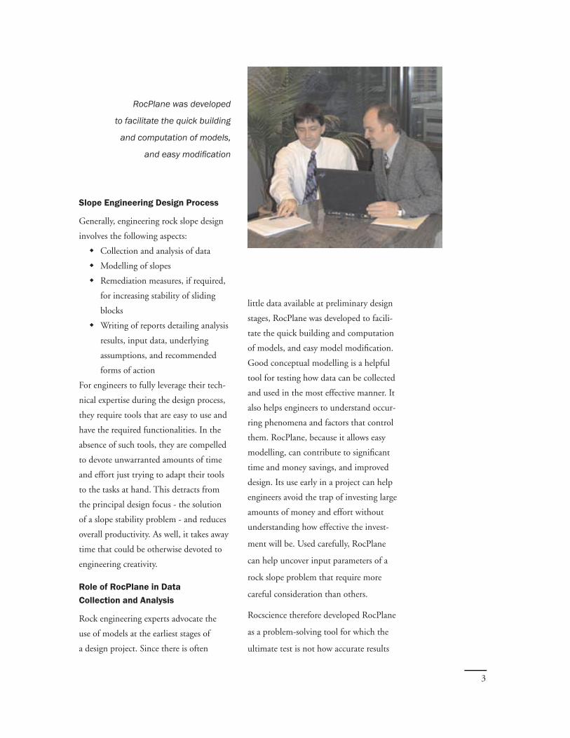
little data available at preliminary design
stages, RocPlane was developed to facili-
tate the quick building and computation
of models, and easy model modifi cation.
Good conceptual modelling is a helpful
tool for testing how data can be collected
and used in the most effective manner. It
also helps engineers to understand occur-
ring phenomena and factors that control
them. RocPlane, because it allows easy
modelling, can contribute to signifi cant
time and money savings, and improved
design. Its use early in a project can help
engineers avoid the trap of investing large
amounts of money and effort without
understanding how effective the invest-
ment will be. Used carefully, RocPlane
can help uncover input parameters of a
rock slope problem that require more
careful consideration than others.
Rocscience therefore developed RocPlane
as a problem-solving tool for which the
ultimate test is not how accurate results
RocPlane was developed
to facilitate the quick building
and computation of models,
and easy modifi cation
3

are, but whether engineers are more
likely to make better decisions with them
than without them. It is designed to facil-
itate the testing of plausible alternative
assumptions and to help assess the conse-
quences of each assumption.
Modelling Methodology
The modelling of rock engineering prob-
lems is generally complex; the interpreta-
tion of data for use in models, the facets
of a problem that must be included in
a model, and the assumptions that are
most appropriate all demand considerable
amounts of professional judgement. This
is why geomechanics modelling is at times
compared to an ‘art’.
For slope design in such an environment,
RocPlane modelling can aid engineers to
gain understanding, and to investigate
potential trade-offs and alternatives.
Although based on a straightforward algo-
rithm, the program’s simplicity ensures
that users have complete intellectual con-
trol of the models they build. Models
are readily understood, and interactions
between important problem parameters
easily evident.
Other Benefi ts of using RocPlane
Combined with the good modelling
methodology that it facilitates, RocPlane
can help slope engineers increase con-
fi dence in their modelling results. The
program’s models, used innovatively, can
forewarn engineers to scenarios or out-
comes not considered beforehand.
RocPlane provides different shear
strength models, groundwater pressure
regimes, and other parameter models that
allow engineers to evaluate the impli-
cations of assumptions they use in anal-
yses. Even when a slope situation is
clearly three-dimensional, RocPlane can
help engineers create models that bracket
the true behaviour of the slope. In many
instances the bounds established in this
fashion are suffi ciently narrow and thus
provide useful information on the actual
real-life situation being modelled.
The program’s simplicity
ensures that users have
complete intellectual control
of the models they build
4
Overview of Planar Slope Stability Analysis
Planar failure is a relatively rare failure mode in rock slopes. This is because the specifi c geometrical
conditions required to produce such a failure are seldom encountered in real slopes. This not withstand-
ing, the study of planar failure mechanisms offers many benefi cial rock slope design insights. This
failure mode is particularly valuable for investigating the sensitivity of slopes to variations in parameters
such as the shear strength of failure surfaces and groundwater conditions.
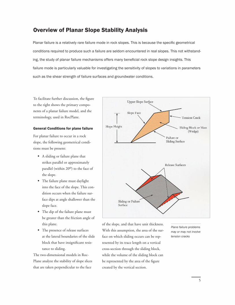
To facilitate further discussion, the fi gure
to the right shows the primary compo-
nents of a planar failure model, and the
terminology, used in RocPlane.
General Conditions for plane failure
For planar failure to occur in a rock
slope, the following geometrical condi-
tions must be present:
A sliding or failure plane that
strikes parallel or approximately
parallel (within 20o) to the face of
the slope.
The failure plane must daylight
into the face of the slope. This con-
dition occurs when the failure sur-
face dips at angle shallower than the
slope face.
The dip of the failure plane must
be greater than the friction angle of
this plane.
The presence of release surfaces
at the lateral boundaries of the slide
block that have insignifi cant resis-
tance to sliding.
The two-dimensional models in Roc-
Plane analyze the stability of slope slices
that are taken perpendicular to the face
Plane failure problems may or may not involve tension cracks
of the slope, and that have unit thickness.
With this assumption, the area of the sur-
face on which sliding occurs can be rep-
resented by its trace length on a vertical
cross-section through the sliding block,
while the volume of the sliding block can
be represented by the area of the fi gure
created by the vertical section.
5

Assumptions in RocPlane
The models in RocPlane are based on
limit equilibrium analysis of a sliding
block. The factor of safety of the slope
or sliding mass is defi ned as the ratio of
the total forces resisting down-slope slid-
ing to the total forces inducing sliding.
The resisting forces comprise the shear
strength of the sliding surface, artifi cial
reinforcement of the slope or other sta-
bilizing external forces, if present. The
driving forces consist of the down-slope
component of the weight of the sliding
block, forces generated by seismic acceler-
ation, forces due to water pressures acting
on various faces of the block, and external
forces on the upper slope surface.
The limit equilibrium models in Roc-
Plane assume that all forces operating
on a sliding block act through the cen-
troid of the block; they ignore overturn-
ing moments. When an analysis involves
a tension crack, it is assumed that the
tension crack, just as the failure plane,
strikes parallel to the slope face.
Whereas many planar wedge analysis
programs consider only vertical tension
cracks, RocPlane allows for non-vertical
tension cracks as well. Non-vertical ten-
sion cracks in RocPlane can have angles of
inclination from the horizontal that can
exceed 90o.
RocPlane also has the following
capabilites:
A variety of water pressure distribu-
tions including user-defi ned distri-
butions. A simple example of
assumed pressure distributions
available in RocPlane is the case
where water enters a sliding plane
from the bottom of a tension
crack and seeps along the sliding
surface, escaping at atmospheric
pressure where the sliding plane
daylights in the slope face.
Five different shear strength models
for sliding planes, namely the
Mohr-Coulomb, Barton-Bandis,
Hoek-Brown, Generalized
Hoek-Brown and Power Curve
models.
A horizontal or non-horizontal
upper slope surface.
A bench analysis mode for design
ing and analyzing the stability of
individual benches in a benched
slope (e.g. open pit mine slope).
6

RocPlane Features
RocPlane is endowed with many features that provide users with the ability to rapidly build and modify
models, and run them. It also includes functionalities for easily analyzing results, generating fi gures and
charts, and producing convenient summaries of models and results.
The report generation features of Roc-
Plane are especially useful to engineers
when writing reports with high-quality,
and professional-looking drawings and
diagrams. They help slope designers to
readily communicate fi ndings to people
with varying slope engineering knowl-
edge. Major features in RocPlane are des-
ribed next.
Creation and Modifi cation of Models
For beginners, or infrequent users of a
software program, it is very necessary to
use an intuitive tool that allows them
to fi nd the features they need to accom-
plish their task with minimum effort. As
a result, a key development goal of Roc-
Plane was to provide an interface that
users can use without extensive experi-
ence with the software.
Easy discovery of model creating tools in
RocPlane is made possible through the
use of:
User friendly dialogs for defi ning
and modifying slope geometry, and
Easy-to-use dialog for entering
other input data
Functionalities that empower users to
rapidly explore a wide variety of situa-
tions include:
An option in the Input Data dialog
for including or excluding a tension
crack
Deterministic analysis for calculat-
ing the factor of safety of a slope or
sliding mass
Sensitivity analysis for evaluating
the infl uence of individual param-
eters upon the factor of safety
Probabilistic analysis for evaluating
the probability or risk of failure of
a slope
Application of multiple external
forces such as reinforcement loads,
or loads from buildings
Different water pressure distribu-
tions for a failure plane and tension
crack (users also have opportunity
to defi ne custom water pressure
distributions)
Application of seismic accelerations
that can destabilize a slope
An intuitive program, RocPlane gives theuser more confi dencein modelling bymaking functionalityeasy to discover.It focuses on making common tasks easyto preform.
7

Input Data Dialog
Data, including geometrical parameters,
for RocPlane models is entered through
an Input Data dialog. This dialog has
unique properties that make it easy to per-
form parametric analysis, or work simul-
taneously with multiple fi les. It can be
minimized or maximized with simple
mouse clicks. Whenever multiple fi les are
open, it automatically displays input data
for the active fi le.
In the Input Data dialog users can enter
deterministic or probabilistic input, based
on the selected analysis mode.
Wedge View
A sliding block or wedge in a model is dis-
played in a four-view, split screen format
showing TOP, FRONT, SIDE and PER-
SPECTIVE views. This feature enhances
perception of the model.
In the Wedge View, users can,
Rotate a model (in the Perspective
View only)
Move the sliding block out of the
slope (in all views)
Resize or maximize the different
views, and
Zoom in or out of the model
Info Viewer
RocPlane has an Info Viewer option that
displays a convenient summary of model
parameters and analysis results. The infor-
mation listed in the Info Viewer is very
useful for inclusion in a report or for
printing.
2D View of Models
In RocPlane users have the option of
viewing a cross-section, taken through a
model, which displays the geometry of
the model (including dimensions), and
the magnitudes of the force, normal to
the failure plane, and driving force. The
2D View also displays a table that sum-
marizes the values of important quantities
such as the factor of safety, wedge weight,
shear force, etc., computed in an analysis.
The Input Data Dialog in RocPlane in the example shown, the dialog isconfi gured for entering data for a deterministic analysis.
8
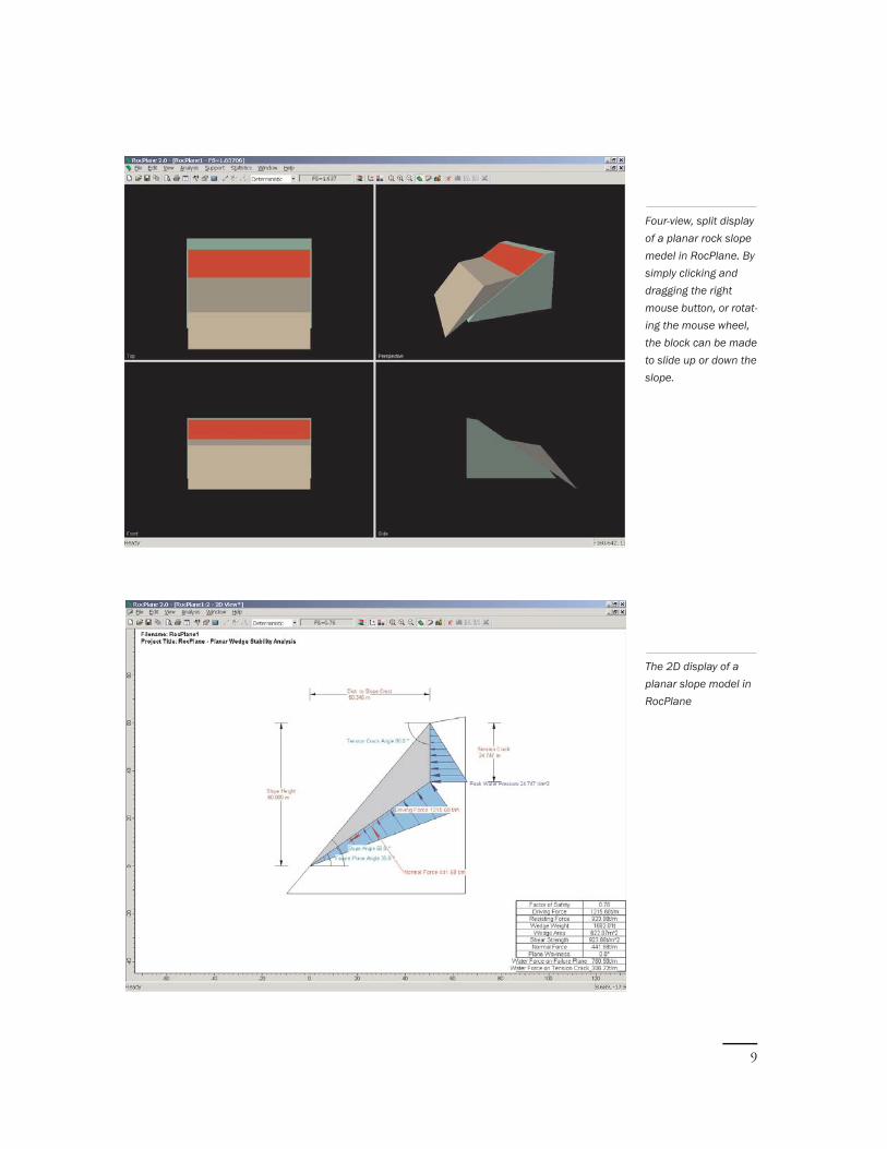
Four-view, split display of a planar rock slope medel in RocPlane. By simply clicking and dragging the right mouse button, or rotat-ing the mouse wheel, the block can be made to slide up or down the slope.
The 2D display of a planar slope model in RocPlane
9

Bench Anlaysis
Normally, RocPlane determines a sliding
block size as defi ned by a failure surface
extending from the toe of a slope to
the upper surface of the slope or to a
tension crack. By selecting the bench
analysis option in the Input Data dialog,
however, a user can defi ne an alternative
(smaller) wedge, scaled to the width of a
bench. This option is very useful for the
design of benches in an open-pit.
One of the most critical components of
any slope stability analysis is the deter-
mination of the water pressure distri-
bution within the slope. Current site
investigation methods are unable to pre-
cisely defi ne groundwater fl ow regimes
in a slope or rock mass. As a result a
slope designer must consider a number
of realistic extremes in order to bracket
the range of possible factors of safety,
and to gauge the sensitivity of a slope to
variations in groundwater conditions.
Some of the plausible groundwater pres-
sure distributions that can be modelled
in RocPlane are described next.
Dry slopes: This is the simplest case that
can be found in rock slopes. When using
this case it is assumed that a slope is com-
pletely drained.
Water in slope with no tension crack:
When no tension crack exists at the top
of the slope a reasonable water pressure
distribution has water intersecting the
failure surface at a specifi ed elevation
above the toe of the slope. It is then
assumed that pressures increase linearly
with depth to a maximum value at
half the specifi ed elevation and thereafter
decreases linearly to zero at the toe of
the slope.
Sliding block in the analysis of a slope bench. The block is scaled to the width of the bench. As such the failure plane does not exit at the slope toe.
Sliding block in the analysis of a complete slope. The block is scaled to the height of the slope by assum-ing that the failure plane paases through the slope toe.
Groundwater Pressure Distribution in RocPlane
10

Water pressure distri-bution ina slope with no tension crack. In this particular case it is assured that the pressure disribution on the failure varies linearly with height, reaching a maximum at the mid-height of the slope.
Simplest assumption of water pressure dis-tribution on sliding surface and tension crack. Here the pres-sure distribution in the tension crack increases linearly from the upper level of the column of water to a maximum value at the base. On the fail-ure plane it decreases linearly from the base of the tension crack to a zero value at the slope face.
11

Water in tension crack and on
sliding surface:
There is a range of plausible water pres-
sure distributions, which are likely for
such conditions. In all of the cases
the water pressure in the tension crack
increases linearly from the upper level of
the water column to the base of the ten-
sion crack.
In the simplest assumption, the pressure
distribution along the sliding surface
decreases linearly from the base of the
tension crack to a zero pressure condition
at the point where water exits from the
slope (the intersection of the failure sur-
face and the slope face). Since the actual
pressure distribution in a slope is often
not known, this assumed distribution is as
reasonable as any other made.
RocPlane considers an alternative water
pressure distribution in which pressures
along the failure plane increase linearly
from the tension crack base, reaches a
maximum value at the mid-height point
of the slope, and then decreases linearly
to the intersection of the failure plane and
the slope face.
More extreme case of water in tension crack
and on sliding surface:
If the exit point of water in a slope
became blocked or clogged for some
reason such as freezing of the slope face
in the winter, water pressure at the face
could be due to the full head of water in
slope instead of a zero pressure condition
at face. Such a water pressure distribution
is more dangerous to the stability of a
sliding block.
Custom Pressure:
The Custom Water Pressure option allows
users to independently specify the average
water pressure on a sliding plane, and on
a tension crack if present. This option
allows the greatest fl exibility in specifying
water pressure distributions, and is very
useful if actual water pressure data for
slopes is available.
Critical Tension Crack Location
When it is not possible to determine the
trace of a tension crack on the upper sur-
face or face of a slope (for example when
a tension crack is obscured by an over-
lying structure) it becomes necessary to
consider the worst-case slope stability sce-
nario. In such situations, RocPlane can
be used to search for the location of
the critical tension crack. The critical ten-
sion crack is the tension crack that, for
a particular slope condition, produces the
lowest factor of safety.
Reinforcement of a Slope/Slope
Stabilization Options
If it is established that a particular slope is
unstable, it becomes expedient to stabilize
the sliding mass. Slopes can be stabilized
through drainage, application of external
loads, fl attening or reduction of slope face
angle, reduction of slope height, or a
combination of measures.
12

External forces or loads that can be
applied to stabilize a sliding block
include measures such as rockbolts, cables
anchored into the rock mass behind fail-
ure surface, or the construction of a waste
rock berm to support the toe of slope.
The effect of a waste rock berm can be
accounted for in RocPlane as external
force specifi ed through a magnitude and
direction.
In the case of reinforcement, RocPlane
allows users to evaluate the number,
length and capacity of bolts needed to
stabilize a sliding block. For deterministic
analysis the program immediately calcu-
lates and displays the factor of safety as
users change various bolt parameters. This
makes it possible for users to interactively
modify bolt properties and see the effect
on stability.
Optimization of bolt orientation: Through
the selection of a simple option in Roc-
Plane, users can optimize individual bolts.
This option automatically determines the
bolt orientation that maximizes the factor
of safety.
Bolt load required to attain specifi ed
factor of safety: RocPlane supplies users
with an option that can calculate the bolt
load required to achieve a specifi ed factor
of safety for a sliding block.
Shear Strength Models
A critical assumption in planar slope
stability analysis involves the shear
strength of the sliding surface. There
are several models in rock engineering
that establish the relationship between
the shear strength of a sliding surface
and the effective normal stress acting on
the plane. RocPlane offers the following
widely accepted shear strength models:
Mohr-Coulomb
Barton-Bandis
Hoek-Brown
Generalized Hoek-Brown, and
Power Curve
Miscellaneous Features
Multiple Document Interface: In RocPlane
users can have several fi les open at the
same time. This feature facilitates the
simultaneous, quick and convenient anal-
ysis and comparison of multiple slope
models. It is very useful for evaluating the
merits of various remedial measures.
Internet Auto-Update Feature: Whenever a
user starts RocPlane, the program checks
for a new update at the Rocscience web-
site. If one is available, RocPlane prompts
the user to download the new version
immediately or asks if the user is to be
notifi ed again after a user-specifi ed period.
Interactive dialogfor specifying and modifying theparameters of a bolt. As soon as any bolt parameters are changed, RocPlane immediately recalcu-lates the factor of safety of the sliding block and displays it in the dialog.
13

Sensitivity Analysis and Sensitivity Plots
The effect of uncertainty in the values of a model’s parameters on results can be explored using a
sensitivity analysis. In sensitivity analysis, values of model parameters are varied across a range of likely
values and the effect on computed factors of safety observed.
This exercise helps identify the parameters
that have the most effect on the stability
of a sliding block, and can be used to
compare the effectiveness of various reme-
dial measures.
RocPlane can generate sensitivity plots,
which are plots of factor of safety results
on the basis of percentage changes in
model parameters specifi ed by users. On
sensitivity plots, the gradient of a curve
for a parameter indicates the effect that
parameter has on the factor of safety of
a sliding mass. Steeper rising or falling
curves indicate greater infl uence on the
factor of safety.
Sensitivity plotsshowing the infl uence of changes in slope angle, slope height, cohesion and the depth of tension crack fi lled with water. From the plots it is evident that changes in slope angle exert the strongest infl u-ence on the stability of the sliding block.
14

Uncertainty and Probabilistic/Stochastic Analysis
Probabilistic or stochastic analysis is used whenever it is important to consider the uncertainty in a
slope’s factor of safety. Estimation of this uncertainty helps to assess the probability or risk of failure
of the slope. Stochastic modelling enables engineers to go beyond the mere assessment of best- or
worst-case scenarios; it also makes it possible for them to evaluate outcomes most likely to occur.
RocPlane supplies the tools needed to per-
form true probabilistic analysis. It allows
users to specify statistical distributions
and ranges for input variables, and auto-
matically run hundreds or even thousands
of possible combinations of the variables
in a model.
Since every remedial measure for stabi-
lizing a sliding mass has a price tag,
RocPlane stochastic modelling can help
engineers and managers to weigh costs
against probability of success.
The histogram plot of the factor of safety results for a proba-bilistic analysis. The best-fi t distribution - a lognormal distribu-tion - for this histo-gram is also shown on the plot.
15

Some of the probabilistic analysis capabili-
ties in RocPlane include:
Statistical distributions (normal,
uniform, triangular, beta, exponen-
tial and lognormal probability
distribution functions) for input
data
Goodness-of-fi t tests for output data
distributions, and
Monte Carlo and Latin Hypercube
probabilistic simulation techniques
An option in RocPlane allows engineers
to include the correlation between the
cohesion and friction angle of sliding sur-
faces modelled with the Mohr-Coulomb
strength relationship, since this correlation
can infl uence expected outcomes.
Data and Results Interpretation Tools
for Probabilistic Analysis
RocPlane users have at their disposal
extensive and fl exible graphical capabil-
ities for interpreting and understanding
the behaviour of a planar failure model.
The program offers the following data
interpretation features:
Graphical output such as histograms
and cumulative (S-curve) distribu-
tions for all statistical input data
and quantities, such as wedge
weight and factor of safety, com-
puted in a model
Scatter plots of variables accompa-
nied by the calculation of correla-
tion coeffi cients and parameters of
best fi t lines for plotted data
Viewing of wedges corresponding
to points on histograms
Export of data from a probabilistic
simulation directly to Microsoft
Excel, the clipboard or a text fi le
Users can generate histograms and cumu-
lative plots for data that they select. On
the histogram plot for a selected variable,
RocPlane lists the mean, standard devia-
tion, minimum and maximum values of
the variable.
RocPlane lets users view sliding block
confi gurations that correspond to points
selected on a histogram or scatter plot.
When a user clicks on a part of a histo-
gram or scatter plot, the program updates
all views such as the Wedge View, 2D
View and Info Viewer so that they display
information for the nearest sliding block
model corresponding to the selected point
on the plot. This feature is useful, for
example, for determining the typical slope
conditions that generate sliding blocks of
a specifi ed factor of safety.
The results of a probabilistic simulation
in RocPlane can be displayed in graphs
and charts within the program, or can
be exported to the familiar interface of
Microsoft Excel with the simple click of
a button. They can also be copied to the
clipboard or to a text fi le. This feature
allows users to further process simulation
results using software with more sophisti-
cated statistical functionalities.
The results of aprobabilisticsimulation in RocPlane can bedisplayed in graphs and charts withinthe program, or can be exported to the familiar interface of Microsoft Excel.
16

Reporting Models and Analysis Results
The communication of model results to managers, colleagues, clients, or the public forms an
important part of the work of engineers. In addition to previously described features, the following
are some of the helpful tools RocPlane supplies, which make the communication of model
information and results easy to perform.
Grayscale option
The Grayscale option in RocPlane is a
toggle that automatically converts all the
views of a current document from colour
to grayscale, or vice versa. Toggled on,
the Grayscale option is useful for sending
images to a monochrome printer, or for
capturing monochrome image fi les.
The histogram plot of the factor of safety results for a probabi-listic analysis shown in grayscale.
Printing
The contents of an active view or window
in RocPlane can be readily printed. Print
output is confi gured to have a profes-
sional look and high quality. Users can
preview the look of the page to be
printed, and can customize the print out-
look by changing parameters such as ori-
entation of the page and margins.
17

Clipboard support
An active view can be captured to the
clipboard with a single command. From
the clipboard, images can be pasted
directly into word or image processing
applications.
Screen Capture to Image File
RocPlane has an Export Image File
option that allows users to save an
active view directly to a JPEG (*.jpg) or
Windows Bitmap (*.bmp) graphics fi le
format.
Concluding Statements
The software allows rock slope engineers
to focus on providing creative and innova-
tive solutions to problems by equipping
them with considerable functionality, and
freeing them from laborious and mun-
dane aspects of their design work. Using
RocPlane, slope designers can gain very
good understanding of planar failure slope
behaviour, and examine many plausible
possibilities with minimal effort.
RocPlane is a problem-solving tool created for engineers by engineers. It lays
out its tools in a well-designed and intuitive manner, and allows speedy building,
modifi cation and computation of models. Combined, these attributes facilitate
good modelling and engineering design practices.
RocPlane helps engineers to achieve the
important maxim that rock mechanics
models should never be run only once,
as the sensitivity of the results to changes
in model parameters and assumptions are
most informing.
18