ROCKY FLATS SITE REGULATORY CONTACT RECORD 2019-02 · Related Contact Records: CR 2013-02, CR...
13
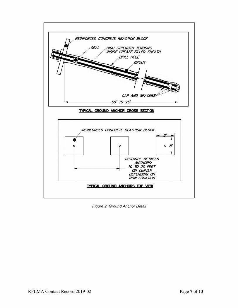
RFLMA Contact Record 2019-02 Page 1 of 13 ROCKY FLATS SITE REGULATORY CONTACT RECORD 2019-02 Purpose: Original Landfill (OLF) Stabilization Project with Soil Disturbance Review Plan Contact Record Approval Date: July 12, 2019 Site Contact(s)/Affiliation(s): Scott Surovchak and Andy Keim, U.S. Department of Energy (DOE); Linda Kaiser, David Ward, and Patty Gallo, Navarro Research and Engineering, Inc. (Navarro) Regulatory Contact(s)/Affiliation(s): Lindsay Masters, Colorado Department of Public Health and Environment (CDPHE); Vera Moritz, U.S. Environmental Protection Agency (EPA) Date of Consultation Meetings: October 16, 2018; April 4, 2019 Consultation Meeting Participants: Lindsay Masters, CDHPE; Scott Surovchak, Andy Keim, DOE; Vera Moritz, EPA; Linda Kaiser, David Ward, Patty Gallo, Jeremy Wehner, John Boylan, George Squibb, Jody Nelson, Michelle Hanson, Navarro Related Contact Records: CR 2013-02, CR 2013-03, CR 2014-09, CR 2015-03, CR 2015-06, CR 2016-03, CR 2016-04, CR 2017-01, CR 2017-04, CR 2018-01 Introduction: The Original Landfill (OLF) Stabilization Project is a maintenance action intended to stabilize the east and west portions of the landfill that were prone to movement since 2007. Geotechnical and civil engineering design firms were contracted in 2017 to investigate and evaluate this movement, propose alternatives to stabilize the areas prone to movement, and design a long-term solution to minimize hillside instability at the OLF. The U.S. Department of Energy (DOE) reviewed the alternatives evaluated by the design subcontractors and selected an alternative that employs ground anchors and subsurface trench drains. This design addresses the two primary contributors to hillside instability identified by the design subcontractors: (1) a weak subsurface soil layer further weakened by movement and (2) groundwater. Discussion: The OLF Stabilization Project design includes the installation of approximately 263 ground anchors with reaction blocks installed in rows on the east and west portions of the OLF (see Approximate Stabilization Area Limits in Figure 1). These ground anchors (Figure 2) will be drilled at an angle into the OLF hillside. Each anchor will be embedded a minimum of 39 feet (ft) into competent bedrock to restrain slide-prone materials. The total lengths for the ground anchors range from approximately 53 to 95 ft. The reaction block at the top of each ground anchor will be an approximately 8 ft × 8 ft × 16-inch reinforced concrete pad that spreads out the restraining load of the ground anchor. When complete, the ground anchors and reaction blocks will be fully buried (i.e., they will not be visible on the ground surface). There will be seven rows of ground anchors on the east end and six rows on the west end of the OLF. Each row of ground anchors will have a subsurface drain (ground anchor drain) installed approximately 8.5 ft below the ground surface that runs the entire length of the row, to drain groundwater away from the concrete reaction blocks. The ground anchor drains will consist of a
Transcript of ROCKY FLATS SITE REGULATORY CONTACT RECORD 2019-02 · Related Contact Records: CR 2013-02, CR...
RFLMA Contact Record 2019-02 Page 1 of 13
ROCKY FLATS SITE REGULATORY CONTACT RECORD 2019-02
Purpose: Original Landfill (OLF) Stabilization Project with Soil Disturbance Review Plan Contact Record Approval Date: July 12, 2019 Site Contact(s)/Affiliation(s): Scott Surovchak and Andy Keim, U.S. Department of Energy (DOE); Linda Kaiser, David Ward, and Patty Gallo, Navarro Research and Engineering, Inc. (Navarro) Regulatory Contact(s)/Affiliation(s): Lindsay Masters, Colorado Department of Public Health and Environment (CDPHE); Vera Moritz, U.S. Environmental Protection Agency (EPA) Date of Consultation Meetings: October 16, 2018; April 4, 2019 Consultation Meeting Participants: Lindsay Masters, CDHPE; Scott Surovchak, Andy Keim, DOE; Vera Moritz, EPA; Linda Kaiser, David Ward, Patty Gallo, Jeremy Wehner, John Boylan, George Squibb, Jody Nelson, Michelle Hanson, Navarro Related Contact Records: CR 2013-02, CR 2013-03, CR 2014-09, CR 2015-03, CR 2015-06, CR 2016-03, CR 2016-04, CR 2017-01, CR 2017-04, CR 2018-01 Introduction: The Original Landfill (OLF) Stabilization Project is a maintenance action intended to stabilize the east and west portions of the landfill that were prone to movement since 2007. Geotechnical and civil engineering design firms were contracted in 2017 to investigate and evaluate this movement, propose alternatives to stabilize the areas prone to movement, and design a long-term solution to minimize hillside instability at the OLF. The U.S. Department of Energy (DOE) reviewed the alternatives evaluated by the design subcontractors and selected an alternative that employs ground anchors and subsurface trench drains. This design addresses the two primary contributors to hillside instability identified by the design subcontractors: (1) a weak subsurface soil layer further weakened by movement and (2) groundwater. Discussion: The OLF Stabilization Project design includes the installation of approximately 263 ground anchors with reaction blocks installed in rows on the east and west portions of the OLF (see Approximate Stabilization Area Limits in Figure 1). These ground anchors (Figure 2) will be drilled at an angle into the OLF hillside. Each anchor will be embedded a minimum of 39 feet (ft) into competent bedrock to restrain slide-prone materials. The total lengths for the ground anchors range from approximately 53 to 95 ft. The reaction block at the top of each ground anchor will be an approximately 8 ft × 8 ft × 16-inch reinforced concrete pad that spreads out the restraining load of the ground anchor. When complete, the ground anchors and reaction blocks will be fully buried (i.e., they will not be visible on the ground surface). There will be seven rows of ground anchors on the east end and six rows on the west end of the OLF. Each row of ground anchors will have a subsurface drain (ground anchor drain) installed approximately 8.5 ft below the ground surface that runs the entire length of the row, to drain groundwater away from the concrete reaction blocks. The ground anchor drains will consist of a
RFLMA Contact Record 2019-02 Page 2 of 13
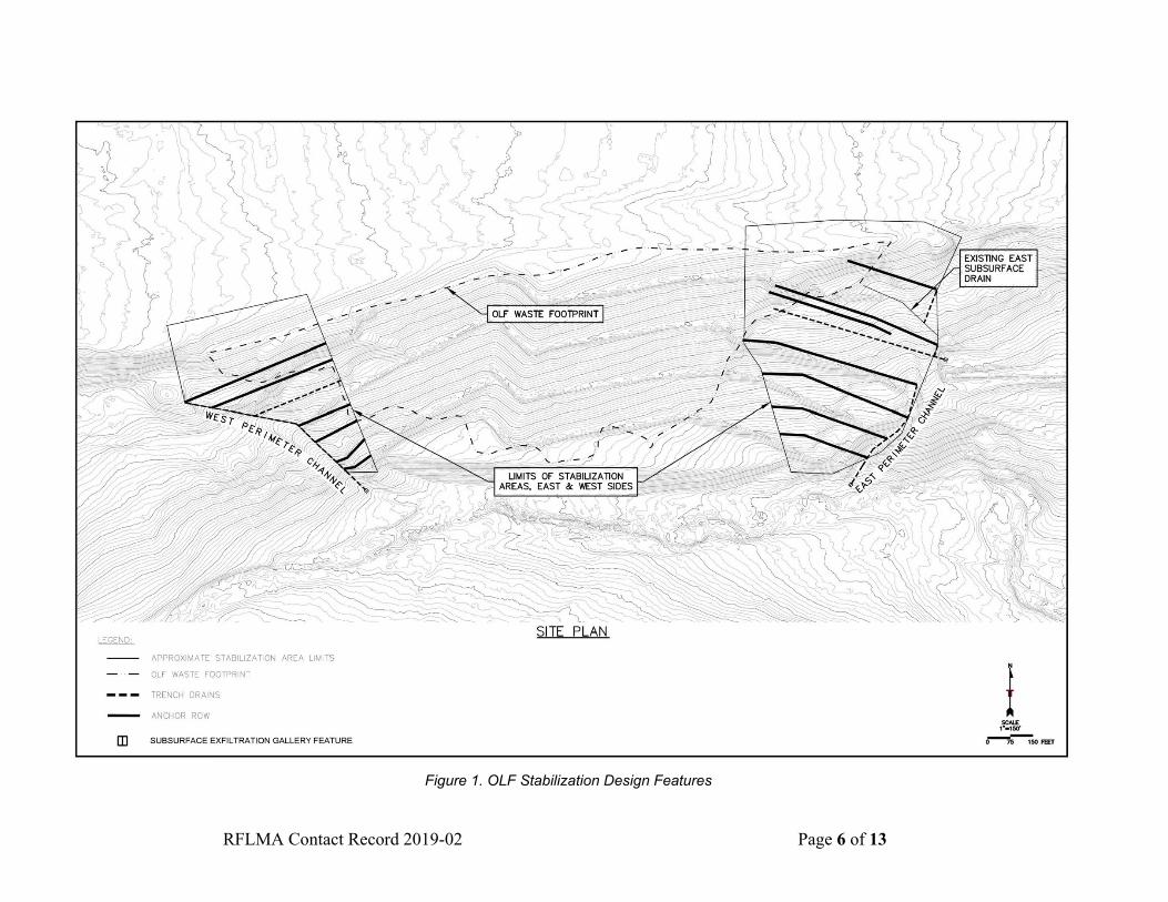
perforated or slotted high-density polyethylene drain pipe surrounded by drain rock and wrapped in geotextile fabric. Figure 3 shows a profile of the anchors and associated ground anchor drains. These drains will flow to subsurface exfiltration gallery features (Figure 4). The groundwater will be diverted to the west in the direction of the existing West Perimeter Channel (WPC) and to the east in the direction of the South Interceptor Ditch (SID) and the East Perimeter Channel (EPC) (Figure 1). The design also includes the installation of one trench drain each on the west and east sides of the landfill (Figure 1). These trench drains are designed to control groundwater elevations on the east and west sides of the landfill area. The trench drain on the east side will be approximately 440 ft long and up to 20 ft deep; the trench drain on the west side will be approximately 300 ft long and up to 20 ft deep. Upon completion of the OLF Stabilization Project, the groundwater collected by the trench drains will be diverted via subsurface drains to the same subsurface exfiltration gallery features connected to the ground anchor drains described above. An additional 900 ft of trench drains will be excavated to complete the subsurface drainage system (e.g., connect the ground anchor and trench drains to the subsurface exfiltration gallery features). Figure 3 shows a profile of the trench drains in relation to the anchors and anchor bench drains. In addition to these major design features, the OLF Stabilization Project will include (1) reinstallation of 2 ft of soil cover within the waste footprint at the east and west edges where movement has occurred in the past (see Approximate Soil Cover Reinstallation Areas in Figure 5), and (2) optimization of the storm-water management system within the Approximate Stabilization Area Limits in Figure 1. Soil Cover. To the extent possible, soil that is excavated from installation of the anchor boreholes and trench drains outside the waste footprint that is not returned to the borehole or trench will be stockpiled for reuse as soil cover. However, additional soil cover material is required for the 2 ft cover over the waste footprint within the two Approximate Soil Cover Reinstallation Areas (Figure 5), as required by the Original Landfill Monitoring and Maintenance Plan (LMS/RFS/S05516) (OLF M&M Plan). This soil cover material will be imported from an off-site source approved by DOE.
The OLF M&M Plan requires that Rocky Flats Alluvium (RFA) be used as soil cover for the OLF. Because the availability of RFA from onsite or off-site sources is limited, the Rocky Flats Legacy Management Agreement (RFLMA) Parties authorize the use of RFA-equivalent material for the soil cover at the OLF. Some of the ground anchors and a portion of the trench drains will be installed within the waste footprint. Consistent with past practices, soil and debris excavated from within the waste footprint will be returned to the excavation within the waste footprint where it originated, in accordance with applicable laws and regulations. This will be achieved through soil compaction and surface contouring, as necessary, to maintain cover drainage. If there is a surplus of landfill material excavated from within the waste footprint that cannot be returned to the excavation from where it came, this material will be buried within the waste footprint at one of the Approximate Soil Cover Reinstallation Areas (Figure 5) on the east or west side, prior to addition of the 2 ft soil cover. Topographic surveys will be completed in these two areas before and after the placement of the waste material, and after the reinstallation of the 2 ft cover to document the cover thickness and ensure that the minimum 2 ft cover requirement was achieved.

RFLMA Contact Record 2019-02 Page 3 of 13
Optimization of Storm-Water Management System. The goal for the optimization of the storm-water management system is to create and maintain positive drainage off the landfill cover while simultaneously minimizing disturbance to the existing cover and established vegetation. Reconfiguration of the existing berms and channels in the central portion of the landfill is not necessary because this area has remained stable since closure. However, installation of the anchor blocks and trenches will require removal of some existing berms and channels within the Approximate Stabilization Area Limits (Figure 1). The berms and channels in these areas will be rebuilt in a slightly different orientation than the original design, to improve storm-water movement off the landfill soil cover. The rebuilt berms and channels will connect to the existing berms and channels to allow for the uninterrupted flow of water off the landfill cover. The reconfigured berms are designed to carry the 100-year, 24-hour design storm. Common borrow, as defined in this contact record (CR), will be used in the reconfiguration of the berms and channels and in the final regrading of the OLF at the end of the project. Maintenance of storm-water structures (e.g., EPC, berms) will be conducted as authorized by the OLF M&M Plan. Operation of the groundwater intercept system and siphon will continue until maintenance construction takes them out of service permanently. DOE plans to start the OLF Stabilization Project field work in August 2019 and complete the work in the spring and summer of 2020. Monthly inspections of the OLF will continue, as required by the OLF M&M Plan, for the duration of the OLF Stabilization Project. Most of the stabilization work will occur on the east and west portions of the landfill, outside the waste footprint. Thus, routine monthly inspection of the soil cover and storm-water features in the central portion of the landfill will continue uninterrupted. However, the RFLMA Parties recognize that inspection of areas where active construction is taking place (generally within the Approximate Stabilization Area Limits in Figure 1) will not be feasible for some periods during the project. For example, the berms and channels within the Approximate Stabilization Area Limits (Figure 1) will be removed to allow construction of the stabilization features (e.g., anchors, trench drains). These berms will ultimately be rebuilt, as described in the paragraph above, but routine inspection of these features will not resume until the OLF Stabilization Project is completed. In addition, some of the seeps are located with the Approximate Stabilization Area Limits (Figure 1), as is the EPC. These features may also not be available for routine inspection for some periods during the Project. Areas and features that cannot be inspected during the OLF Stabilization Project will be noted on the inspection form. Routine inspections of these areas and features in accordance with the OLF M&M Plan will resume as soon as practicable. The RFLMA Parties acknowledge that certain features of the OLF will not be routinely inspected during the OLF Stabilization Project and agree that this does not constitute noncompliance with the inspection requirements of the OLF M&M Plan. Construction of the OLF stabilization features (anchors and trench drains) will occur in the vicinity of two existing settlement monuments installed during OLF closure: settlement monument F on the east side and settlement monument E on the west side of the landfill. Every effort will be made to protect these monuments during construction. Monuments will be replaced if damaged or otherwise rendered unusable. Approval of this CR does not formally modify the OLF M&M Plan; however, the RFLMA Parties agree that the M&M Plan shall be modified to incorporate changes to the landfill features resulting from implementation of the OLF Stabilization Project.
RFLMA Contact Record 2019-02 Page 4 of 13
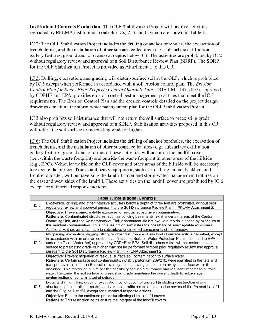
Institutional Controls Evaluation: The OLF Stabilization Project will involve activities restricted by RFLMA institutional controls (ICs) 2, 3 and 6, which are shown in Table 1. IC 2: The OLF Stabilization Project includes the drilling of anchor boreholes, the excavation of trench drains, and the installation of other subsurface features (e.g., subsurface exfiltration gallery features, ground anchor drains) at depths below 3 ft. The activities are prohibited by IC 2 without regulatory review and approval of a Soil Disturbance Review Plan (SDRP). The SDRP for the OLF Stabilization Project is provided as Attachment 1 to this CR. IC 3: Drilling, excavation, and grading will disturb surface soil at the OLF, which is prohibited by IC 3 except when performed in accordance with a soil erosion control plan. The Erosion Control Plan for Rocky Flats Property Central Operable Unit (DOE-LM/1497-2007), approved by CDPHE and EPA, provides erosion control best management practices that meet the IC 3 requirements. The Erosion Control Plan and the erosion controls detailed on the project design drawings constitute the storm-water management plan for the OLF Stabilization Project. IC 3 also prohibits soil disturbance that will not return the soil surface to preexisting grade without regulatory review and approval of a SDRP. Stabilization activities proposed in this CR will return the soil surface to preexisting grade or higher. IC 6: The OLF Stabilization Project includes the drilling of anchor boreholes, the excavation of trench drains, and the installation of other subsurface features (e.g., subsurface exfiltration gallery features, ground anchor drains). These activities will occur on the landfill cover (i.e., within the waste footprint) and outside the waste footprint in other areas of the hillside (e.g., EPC). Vehicular traffic on the OLF cover and other areas of the hillside will be necessary to execute the project. Trucks and heavy equipment, such as a drill rig, crane, backhoe, and front-end loader, will be traversing the landfill cover and storm-water management features on the east and west sides of the landfill. These activities on the landfill cover are prohibited by IC 6 except for authorized response actions.
Table 1. Institutional Controls IC 2 Excavation, drilling, and other intrusive activities below a depth of three feet are prohibited, without prior
regulatory review and approval pursuant to the Soil Disturbance Review Plan in RFLMA Attachment 2.
Objective: Prevent unacceptable exposure to residual subsurface contamination. Rationale: Contaminated structures, such as building basements, exist in certain areas of the Central Operating Unit, and the Comprehensive Risk Assessment did not evaluate the risks posed by exposure to this residual contamination. Thus, this restriction eliminates the possibility of unacceptable exposures. Additionally, it prevents damage to subsurface engineered components of the remedy.
IC 3
No grading, excavation, digging, tilling, or other disturbance of any kind of surface soils is permitted, except in accordance with an erosion control plan (including Surface Water Protection Plans submitted to EPA under the Clean Water Act) approved by CDPHE or EPA. Soil disturbance that will not restore the soil surface to preexisting grade or higher may not be performed without prior regulatory review and approval pursuant to the Soil Disturbance Review Plan in RFLMA Attachment 2.
Objective: Prevent migration of residual surface soil contamination to surface water. Rationale: Certain surface soil contaminants, notably plutonium-239/240, were identified in the fate and transport evaluation in the Remedial Investigation as having complete pathways to surface water if disturbed. This restriction minimizes the possibility of such disturbance and resultant impacts to surface water. Restoring the soil surface to preexisting grade maintains the current depth to subsurface contamination or contaminated structures.
IC 6 Digging, drilling, tilling, grading, excavation, construction of any sort (including construction of any structures, paths, trails, or roads), and vehicular traffic are prohibited on the covers of the Present Landfill and the Original Landfill, except for authorized response actions.
Objective: Ensure the continued proper functioning of the landfill covers. Rationale: This restriction helps ensure the integrity of the landfill covers.

RFLMA Contact Record 2019-02 Page 5 of 13
The lower half of the OLF is within critical habitat for the Preble’s meadow jumping mouse (Zapus hudsonius preblei). Work that occurs within the original OLF construction boundary is still covered by the 2004 Programmatic Biological Assessment and Biological Opinion. However, because part of this project will occur outside the original construction boundary, a separate consultation document will be submitted to the U.S. Fish and Wildlife Service to address the additional area needed for the project. Resolution: CDPHE, after reviewing information regarding the proposed soil disturbance and excavation and after consultation with EPA, has approved the OLF Stabilization Project activities described in this CR. CDPHE has determined that the proposed activities are not expected to: (1) compromise or impair the function of the remedy, or (2) result in an unacceptable release or exposure to residual subsurface contamination. CDPHE has also determined that the proposed activities meet the rationale and objectives of IC 2, 3 and 6. Therefore, certain activities normally prohibited by these institutional controls are authorized by this CR solely for the purpose of implementing the OLF Stabilization Project. Approval of this CR constitutes authorization to implement the actions described herein. The work will be conducted after approval of this CR, but DOE will not conduct the approved soil disturbance until 10 calendar days after this CR is posted on the Rocky Flats website and stakeholders are notified of the posting in accordance with the RFLMA Public Involvement Plan. Progress and the completion of the work will be reported by DOE in RFLMA quarterly and annual reports of surveillance and maintenance activities for the period(s) in which these activities occur. Actions Complete: The actions approved by this CR will be considered complete when the OLF Stabilization Project actions approved by this CR are completed, post-construction reseeding has been performed, and post-construction erosion controls are in place. At that time, the reportable condition at the OLF described by CR 2013-02 will be resolved. Contact Record Prepared by: Patty Gallo, David Ward, and Jeremy Wehner, Navarro Distribution: Lindsay Masters, CDPHE Vera Moritz, EPA
Scott Surovchak, DOE Andy Keim, DOE
Linda Kaiser, Navarro Rocky Flats Contact Record File
RFLMA Contact Record 2019-02 Page 6 of 13
Figure 1. OLF Stabilization Design Features
RFLMA Contact Record 2019-02 Page 7 of 13
Figure 2. Ground Anchor Detail

RFLMA Contact Record 2019-02 Page 8 of 13
Figure 3. Ground Anchor and Trench Profile

RFLMA Contact Record 2019-02 Page 9 of 13
Figure 4. Subsurface Exfiltration Gallery Feature

RFLMA Contact Record 2019-02 Page 10 of 13
Figure 5. Soil Cover Reinstallation Areas

RFLMA Contact Record 2019-02 Page 11 of 13
Attachment 1
Rocky Flats Legacy Management Agreement Soil Disturbance Review Plan
Proposed Project: Soil Disturbance Review Plan (SDRP) for the Original Landfill (OLF) Stabilization Project This SDRP provides information required by the Rocky Flats Legacy Management Agreement (RFLMA) Attachment 2, “Legacy Management Requirements,” Section 4.1, “Soil Disturbance Review Plan,” regarding the work proposed by DOE. Description of the proposed project, including the purpose, the location, and the lateral and vertical extent of excavation. The Original Landfill (OLF) Stabilization Project is a maintenance action intended to stabilize the east and west portions of the landfill. The project will involve implementation of an engineered design that includes installation of ground anchor blocks and trench drains. This design addresses the two primary contributors to hillside instability: (1) a weak subsurface soil layer further weakened by movement and (2) groundwater. This project is intended to address the long-term stabilization of the OLF hillside. Approximately 263 ground anchors with reaction blocks will be installed in rows on the east and west portions of the OLF where past movement and slumping have occurred (see Approximate Stabilization Area Limits in Figure 1 to CR 2019-02). These ground anchors will be drilled at an angle into the OLF hillside. Each anchor will be embedded a minimum of 39 feet (ft) into competent bedrock to restrain slide-prone materials. The total lengths for the ground anchors range from approximately 53 ft to 95 ft. The reaction block at the top of each ground anchor will be an approximately 8 ft × 8 ft × 16-inch reinforced concrete pad that spreads out the restraining load of the ground anchor. When complete, the ground anchors and reaction blocks will be fully buried (i.e., they will not be visible on the ground surface). There will be seven rows of ground anchors on the east end and six rows on the west end of the OLF. Each row of ground anchors will have a subsurface drain installed approximately 8.5 ft below the ground surface that runs the entire length of the row, to drain groundwater away from the landfill. These drains will flow to subsurface exfiltration gallery features that will allow groundwater to express at the ground surface in a manner similar to that of a seep (see Figure 4 to CR 2019-02). The groundwater collected by the ground anchor drains, and the trench drains described in the following paragraph, will be diverted to the west in the direction of the existing West Perimeter Channel and to the east in the direction of the South Interceptor Ditch (SID) and the East Perimeter Channel (EPC) (Figure 1 to CR 2019-02). The design also includes the installation of one trench drain each on the west and east sides of the landfill (see Figure 1 to CR 2019-02). These trench drains are designed to control groundwater elevations within the landfill area. The trench drain on the east side will be approximately 440 ft long and up to 20 ft deep; the trench on the west side will be approximately 300 ft long and up to 20 ft deep. Upon completion of the OLF stabilization project, the groundwater collected by the trench drains will be diverted via subsurface drains to the same subsurface exfiltration gallery features connected to the ground anchor drains described above. An additional 900 ft of trench drains will be installed to complete the subsurface drainage system (e.g., connect the ground anchor and trench drains to the subsurface exfiltration gallery features).

RFLMA Contact Record 2019-02 Page 12 of 13
DOE has conducted intrusive activities at the OLF, some of which occurred at locations within the waste footprint, several times since closure in 2005. Activities that involved soil disturbance (e.g., drilling, excavation) are listed below, along with the associated CRs:
• Investigation, repairs, and maintenance, including WPC regrade in 2008 (CR 2008-07)
• Soil sampling in 2010 (CR 2010-01)
• Regrading the EPC in 2013 (CR 2013-03 and CR 2014-09)
• Response to precipitation in 2015 (CR 2015-03 and CR 2015-06)
• Upgrade of East Subsurface Drain in 2016 (CR 2016-04)
• Interim maintenance work in 2017 (CR 2017-04)
• Geotechnical investigation in 2018 (CR 2018-01) Additional information on these activities may be found in the Annual Report of Site Surveillance and Maintenance Activities at the Rocky Flats Site, Colorado for the calendar year in which the activity took place. Information about any remaining subsurface structures in the vicinity of the proposed project (or state that there are none if that is the case). There are no remaining subsurface structures (e.g., buried buildings, foundations) in the vicinity of the proposed project. An abandoned buried natural gas line operated by Xcel Energy is in the utility easement corridor north of the OLF. The location and alignment of this abandoned line is well known and marked with signs. It is well outside of the soil disturbance areas. Prior to OLF closure, a subsurface storm-water drain was present that cut across the northeast portion of the landfill and ended at the SID. This drain was abandoned during closure; part of the drain was removed and part of it was closed in place. The remnants of this drain have been shown to be a preferential pathway for groundwater originating on the pediment north of the landfill. During the 2018 geotechnical investigation at the OLF, the terminus of this storm-water drain was located. As part of the OLF Stabilization Project, the terminus will be connected to the trench drain that will be constructed on the east side of the landfill. Information about any former Individual Hazardous Substance Sites (IHSSs), Potential Areas of Concern, or other known or potential soil or groundwater contamination in the vicinity of the proposed project. The OLF is located on a south-facing hill slope north of Woman Creek. The landfill covers approximately 20 acres that encompasses two IHSSs: IHSS 115 (OLF), and IHSS 196 (Water Treatment Plant Backwash Pond). IHSS 196 was in the approximate center of the OLF. From the early 1950s until the 1970s, filter backwash wastewater generated by the nearby water treatment plant was discharged to a settling and evaporation pond (IHSS 196). The effluent from the water treatment plant was discontinuous and was made up of filter backwash, filter prewash, sludge blowdown, and other wastewater from the treatment of raw water. It contained all the silt, mud, and filterable solids removed from the raw water.

RFLMA Contact Record 2019-02 Page 13 of 13
The OLF (IHSS 115) was not designed or operated as an engineered landfill. The OLF is not a hazardous waste unit because wastes were not disposed of in the landfill after the effective dates of the various hazardous waste regulations. However, the OLF’s historical use is typical of solid waste dumps of the time, and the wastes disposed of were plant trash and construction debris that, based on sampling, likely contained some chemicals that subsequently were regulated as Comprehensive Environmental Response, Compensation, and Liability Act hazardous substances. The Final Interim Measure/Interim Remedial Action for the Original Landfill (IM/IRA) describes the history of the OLF and the types of wastes disposed of in the landfill (DOE 2005). Use of the OLF for dumping trash and debris ended in 1968, and an unknown amount of soil was used to cover the waste. The OLF IM/IRA states that soil was used to cover the waste dumped in the OLF area during its use, and that the waste and soil are fairly well commingled. The OLF was not a radioactive contaminated waste disposal area. However, there is a documented instance of placing a smoldering depleted uranium (DU) slab in the OLF to allow it to “burn out.” When the burned slab was recovered, not all of the DU mass was recovered. Surface soil monitoring at the OLF also located several hot spots. Before the soil cover was placed on the OLF, the hot spots were removed (see OLF IM/IRA, Appendix E). The OLF IM/IRA contains environmental media analytical results, including results from 57 surface soil locations and 22 subsurface soil (to bedrock) borehole locations. A review of the OLF IM/IRA residual soil contamination data shows that concentrations of all analytes are below the Wildlife Refuge Worker (WRW) subsurface soil Preliminary Remediation Goals, which are based on 1 × 10⁻⁶ risk from activities involving occasional exposure to subsurface soils, such as drilling. The OLF is within the Upper Woman Drainage Exposure Unit (EU) evaluated in the Comprehensive Risk Assessment, Appendix A, of the Remedial Investigation/Feasibility Study. The only contaminants of concern (COCs) identified for this EU are benzo[a]pyrene and dioxins/furans for surface soil/surface sediment. Dioxin/furan concentrations were converted to 2,3,7,8-tetrachlorodibenzo-p-dioxin (TCDD) toxicity equivalents (TEQs) for COC screening and risk characterization. Noncancer risks for benzo[a]pyrene and 2,3,7,8-TCDD TEQ were not evaluated because those COCs do not have noncancer toxicity values. Risks were calculated for benzo[a]pyrene and 2,3,7,8 TCDD TEQ. The estimated Tier 1 total excess lifetime cancer risk to the WRW at the EU is 8 × 10⁻⁶, and the Tier 2 risk is 4 × 10⁻⁶. A portion of the “Industrial Area Plume,” which contains groundwater contaminated with volatile organic compounds (VOCs), has been mapped as extending beneath the northern part of the OLF. Based on pre-closure data, this area of the plume is characterized by low (part-per-billion) concentrations of VOCs. There are three Resource Conservation and Recovery Act wells positioned at the bottom of the OLF to monitor the groundwater that has passed through the landfill. In addition, surface water monitoring location GS59 monitors surface water downstream of the OLF in Woman Creek and the WOMPOC monitoring location ensures that surface water leaving the Central Operable Unit meets applicable RFLMA standards. The OLF closure design had a 2-foot-thick soil cover over the location of the disposed of waste materials and clean RFA fill surrounding the waste materials for the placement and configuration of storm-water and seep water management features. The limits of the waste area (i.e., waste footprint) are shown in Figure 1 of CR 2019-02. Because some drilling and excavation will take place within the OLF waste footprint, it is possible that workers will be exposed to contaminated soils, buried wastes, or contaminated groundwater. Contamination control, worker protection, and identification and characterization processes are addressed in the project planning documents for the OLF Stabilization Project.