
Rockwell PLC with EtherNet IP - Aimco Global · Under the Communications tab at the top of the...
11
10000 SE Pine Street Portland, OR 97216 TEL: 800.852.1368 FAX: 503.262.3410 www.aimco-global.com Using an AIMCO Gen 4 Controller on a Rockwell PLC with EtherNet IP Authors: Kade Olson and Sam Stewart Date: June 18, 2015 Introduction Many AIMCO torque controllers come standard with EtherNet IP. A common use is interfacing them to an Allen-Bradley PLC for error proofing and data collection. This document is intended to show the steps required to setup the PLC and AIMCO controller for EtherNet IP communication. Equipment/Software • EtherNet IP capable controller from AIMCO. o Generation 4 controller (iEC4EGVP). • 1769-L32E CompactLogix5332E Controller Rev 16.20. • RSLogix 5000 Rev v16.3. • 3 – Ethernet cables. Hardware Setup • Connect an Ethernet cable from the CompactLogix L32E to an Ethernet switch. • Connect an Ethernet cable from the PC to an Ethernet switch. • Connect an Ethernet cable from the AIMCO controller to an Ethernet switch.
Transcript of Rockwell PLC with EtherNet IP - Aimco Global · Under the Communications tab at the top of the...
10000 SE Pine Street
Portland, OR 97216
TEL: 800.852.1368
FAX: 503.262.3410
www.aimco-global.com
Using an AIMCO Gen 4 Controller on a
Rockwell PLC with EtherNet IP Authors: Kade Olson and Sam Stewart
Date: June 18, 2015
Introduction Many AIMCO torque controllers come standard with EtherNet IP. A common use is interfacing
them to an Allen-Bradley PLC for error proofing and data collection. This document is intended to
show the steps required to setup the PLC and AIMCO controller for EtherNet IP communication.
Equipment/Software • EtherNet IP capable controller from AIMCO.
o Generation 4 controller (iEC4EGVP).
• 1769-L32E CompactLogix5332E Controller Rev 16.20.
• RSLogix 5000 Rev v16.3.
• 3 – Ethernet cables.
Hardware Setup • Connect an Ethernet cable from the CompactLogix L32E to an Ethernet switch.
• Connect an Ethernet cable from the PC to an Ethernet switch.
• Connect an Ethernet cable from the AIMCO controller to an Ethernet switch.

10000 SE Pine Street
Portland, OR 97216
TEL: 800.852.1368
FAX: 503.262.3410
www.aimco-global.com
Initial Setup
Configuring the AIMCO Controller
Go to any web browser and navigate to the IP address of the Gen 4 controller (AIMCO Controllers
come default with IP Address 10.10.30.150). This step can also be done from the AIMCO
controller itself. Click on the ‘Controller’ option and select ‘Communication Interfaces’ to bring up
the Communication settings of the controller. This setup has the following values:
Figure 1 Gen 4 Controller Communication Settings
Return to the ‘Controller’ menu and select ‘I/O’ to bring up the Inputs and Outputs of various modes of communication. Since we are using EtherNet IP, we will need to create input and output variables since no defaults exist. To create a variable, click the ‘plus’ symbol on the left of the screen. Select which bit/bits you would like to enable and click the green check mark. For simplicity, choose only one bit with element type ‘Int16’ for the input (stop bit) and output (OK). These steps are shown in Figure 2. Be sure that the controller is configured as shown.

10000 SE Pine Street
Portland, OR 97216
TEL: 800.852.1368
FAX: 503.262.3410
www.aimco-global.com

10000 SE Pine Street
Portland, OR 97216
TEL: 800.852.1368
FAX: 503.262.3410
www.aimco-global.com
Figure 2 Controller EtherNet IP Settings
Pay no attention to any activated bits. These will be resolved once you download the EtherNet IP
configuration onto the PLC.
Defining the CompactLogix L32E Module for the PLC
Initialize the RSLogix5000 software. Create a new project and make sure that the ‘Type’ and
‘Revision’ fields match the PLC controller being used. After a ‘Name’ and ‘Description' are created,
select a destination where you will save the project (see Figure 3). Click OK.
10000 SE Pine Street
Portland, OR 97216
TEL: 800.852.1368
FAX: 503.262.3410
www.aimco-global.com
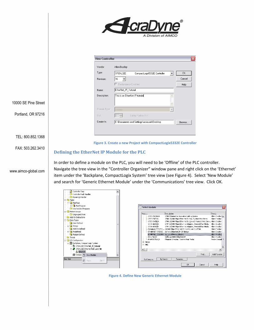
Figure 3. Create a new Project with CompactLogix5332E Controller
Defining the EtherNet IP Module for the PLC
In order to define a module on the PLC, you will need to be ‘Offline’ of the PLC controller.
Navigate the tree view in the “Controller Organizer” window pane and right click on the ‘Ethernet’
item under the ‘Backplane, CompactLogix System’ tree view (see Figure 4). Select ‘New Module’
and search for ‘Generic Ethernet Module’ under the ‘Communications’ tree view. Click OK.
Figure 4. Define New Generic Ethernet Module

10000 SE Pine Street
Portland, OR 97216
TEL: 800.852.1368
FAX: 503.262.3410
www.aimco-global.com
Setting up the Connection
The AIMCO controller has two connection assemblies, Input and Output. The AIMCO controller’s
produced output image (Assembly Instance 112) has a default size of 0 x (16 bit) INTS. The AIMCO
controller’s consumed input image (Assembly Instance 100) is also a default size of 0 x (16 bit)
INTS. In order to communicate over EtherNet IP, RSLogix and the AIMCO controller bit sizes must
match. More examples are shown at the end of this document.
Configuring the Connection
Configuring the connection will require you to define several pieces of information. See Figure 5
• Name of the Module – This will be used as an RSLogix references for Tags.
• Description of the Module.
• Comm Format – Change from default to “Data – INT”.
• IP Address of the targeted controller (in our example we have set it to 10.10.13.117)
• Connection Parameters
o PLC Input Assembly 101 set to 1 x (16 bit) INTS.
o PLC Output Assembly 100 set to 1 x (16 bit) INTS.
o PLC Configuration set to 150 size of 0 bytes.
Figure 5 Defining the EtherNet IP Module

10000 SE Pine Street
Portland, OR 97216
TEL: 800.852.1368
FAX: 503.262.3410
www.aimco-global.com
Click ‘OK’ button when you have defined the module. RSLogix will then ask you to set module
properties. The only property that you need to change from default is the Request Packet Interval
(RPI).
• Request Packet Interval (RPI) set to 100ms. See Figure 6.
Figure 6 Defining the EtherNet IP Module
The Ethernet module should be defined in the RSLogix ‘Controller Organized’ tree view pane with
the <ETHERNET-MODULE Name_of_Module> given in the above section.
Downloading the configuration
Under the Communications tab at the top of the RSLogix 5000 screen, select ‘Who Active’. In this
example a gateway has already been established therefore we can expand ‘AB_ETHIP-1, Ethernet’
tab and click ‘Refresh’ (If this has not been configured, it must be done in RSLinx. Refer to
document ‘Configuring Communication between the PC and the Rockwell PLC’ for further
assistance with this). All the active addresses on the network created will remain without a red
‘X’ (see Figure 7). Expand the tree on the IP address that corresponds to the PLC controller you
are using. Click on ’00, CompactLogix Processor’ under the ‘Backplane, CompactLogix System’ and
select ‘Download’ to the right of the menu.

10000 SE Pine Street
Portland, OR 97216
TEL: 800.852.1368
FAX: 503.262.3410
www.aimco-global.com
Figure 7 Defining the EtherNet IP Module
Follow the prompts. The program will ask if you would like to ‘Change the controller mode back
to remote run’. Click Yes.
Adding the Logic
Tags
RSLogix will automatically define ‘Controller Tags’ in the project file that reference module name
as configured in Figure 5.
Figure 8 EtherNet IP PLC Controller Tags
It is important to note that RSLogix defines its PLC Controller tags as ‘INT’ type. This means that
every memory index will actually hold two bytes of data.
Read/Write to the AIMCO Controller
Now that EtherNet IP is configured, we need to establish some logic variables to confirm proper
functionality. Under the menu ‘MainProgram’, double click on ‘Program Tags’. At the bottom of
the screen, select ‘Edit Tags’ and click on the blank cell under the ‘Name’ column to create a
variable. In this example, we will create two variables that will output to the AIMCO controller
and tell the tool to stop (see Figure 9). Make sure that the ‘Stop_Button’ variable has a ‘BOOL’

10000 SE Pine Street
Portland, OR 97216
TEL: 800.852.1368
FAX: 503.262.3410
www.aimco-global.com
data type and that the second variable, ‘Stop’, is aliased to output over the EtherNet IP Ethernet
port (The data type should automatically change to ‘BOOL’).
Figure 9 EtherNet IP PLC Program Tags
Before you download any of the configuration to the PLC, you need to create the ladder logic.
Navigate back to ‘MainRoutine’ and create the setup shown in Figure 10.
Figure 10 EtherNet IP PLC Ladder Logic
Download the new settings to the PLC controller. The ‘Stop_Button’ variable can now be toggled
by selecting the ladder element and pressing ctrl+T on the keyboard.
Additional Examples
It is important that the Gen 4 controller and RSLogix configuration match. For example, if the
AIMCO controller has 3-16 bit input and output integers, RSLogix must have a value of 3 in both
the ‘Input’ and ‘Output’ field in the ‘Module Properties’. It must also have the ‘Comm Format’ set
to ‘Data-INT’. See below.
10000 SE Pine Street
Portland, OR 97216
TEL: 800.852.1368
FAX: 503.262.3410
www.aimco-global.com
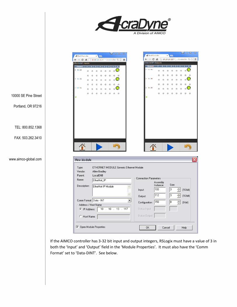
If the AIMCO controller has 3-32 bit input and output integers, RSLogix must have a value of 3 in
both the ‘Input’ and ‘Output’ field in the ‘Module Properties’. It must also have the ‘Comm
Format’ set to ‘Data-DINT’. See below.

10000 SE Pine Street
Portland, OR 97216
TEL: 800.852.1368
FAX: 503.262.3410
www.aimco-global.com