
Nose Cone & Fin Optimization Tripoli Minnesota Gary Stroick January 2011.

Rocket Design
Tripoli Minnesota
Gary Stroick
February 2010

Copyright © 2010 by Gary Stroick 2
Purpose
Focus is on designing
aerodynamically stable rockets
not drag optimization nor
construction techniques!
Copyright © 2010 by Gary Stroick 3
Agenda
• Overview
• Airframes
• Fins
• Nose Cones
• Altimeter Bays
• Design Rules of Thumb
• Summary

Copyright © 2010 by Gary Stroick 4
Overview
• Mission
• Design Considerations
• Design Implications

Copyright © 2010 by Gary Stroick 5
Mission
• Certification (Level 1, 2, or 3)
• Altitude
• Velocity/Acceleration
• Payload (Liftoff Weight)
• Design Experiments
• Recovery
• Motors
• Structural: Nose Cone, Fins, Transitions
• Staging
• Electronics: Cameras, Sensors, …
Copyright © 2010 by Gary Stroick 6
Design Considerations
• Aerodynamic Stability
• Static
• Dynamic
• Optimization
• Drag: Pressure, Viscous (Surface
Roughness, Interference, Base, Parasite)
Angle of Attack, Rotation
• Mass
• Flexibility
• Motor Sizes
• Airframe Configurations

Copyright © 2010 by Gary Stroick 7
Design Considerations
• Key Concepts
• Center of Gravity
• Center of Pressure
• Damping Ratio
• Corrective Moment
• Damping Moment
• Longitudinal Moment
• Roll Stabilization

Copyright © 2010 by Gary Stroick 8
Design Considerations:
Center of Gravity (CG)
• CG ia a single point through which all
rotation occurs
• Sum of the product of weights and
distance from a reference point
CG=(dnw
n+d
rw
r+d
aw
a+d
ew
e+d
fw
f)/W
Refere
nce P
oint
dn
wn
wr
wa
wf
we
dr
da
de
df
Roll Axis
Yaw Axis
Pitch Axis
Wind
Thrust

Copyright © 2010 by Gary Stroick 9
Design Considerations:
Center of Pressure (CP)
• CP is a single point through which all aerodynamic forces
act
• Barrowman’s Method (Subsonic only)
• Sum of the product of projected area, angle of attack, normal
force, air density, airspeed, and distance from a reference
point (simplification - requires integration)
CP=(cnn
n+c
fn
f)/N
• Calibers = (CP-CG)/dmax
Refere
nce P
oint
cn
nn
nf
cf
Symmetry Axis
Lift
Flight Direction
α
Drag

Copyright © 2010 by Gary Stroick 10
Design Considerations:
Damping Ratio (DR)
• Applicable to both impulsive (wind
gusts, thrust anomalies) and
continuous (rail guides, fins) forces
• Over damping and significant under
damping results in large flight
deflections
• Optimum damping ratio is .7071
• Under damping is preferred to over
damping

Copyright © 2010 by Gary Stroick 11
Design Considerations:
Damping Ratio (cont)
Critically Damped (ζ=1)
t
α
Amax
Overdamped Response
t
α
Amax
Underdamped Response
t
α
Amax
Zero Damping (Natural Frequency @ Airspeed)
t
α
Amax

Copyright © 2010 by Gary Stroick 12
Design Considerations:
Corrective Moment (CM)
• An angular velocity which redirects nose
to flight path in response to an angle of
attack.
• C1=
ρ/2v
2A
rN
α(CP-CG) – subsonic only
• Variables:
• Air Density (ρ) – decreasing
• Velocity (v) – increases then decreases
• Reference Area (Ar) – usually constant
• Normal Force Coefficient (Nα) – increasing
• CP – constant (unless supersonic)
• CG – changes (usually forward)
gpr CCNAvC
2
12
gpr CCNAvC
2
12

Copyright © 2010 by Gary Stroick 13
Design Considerations:
Damping Moment (DM)
• Response to corrective moment
(minimizes overcorrection by
slowing angular velocity).
• Comprised of two components:
• Aerodynamic
• Varies based on air density, velocity,
reference area, and CG
• Propulsive
• Applicable only during motor thrust
• Varies based on mass flux

Copyright © 2010 by Gary Stroick 14
Design Considerations:
Longitudinal Moment (LM)
• Mass distribution along longitudinal
axis
• Point mass assumptions appropriate
for components distant from CG
(underestimate)
• Large values of LM reduce
sensitivity to impulsive forces and
protect against over damping
Copyright © 2010 by Gary Stroick 15
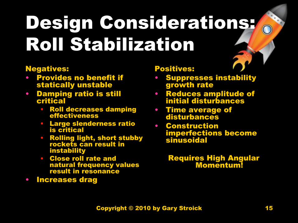
Design Considerations:
Roll Stabilization
Negatives:
• Provides no benefit if
statically unstable
• Damping ratio is still
critical
• Roll decreases damping
effectiveness
• Large slenderness ratio
is critical
• Rolling light, short stubby
rockets can result in
instability
• Close roll rate and
natural frequency values
result in resonance
• Increases drag
Positives:
• Suppresses instability
growth rate
• Reduces amplitude of
initial disturbances
• Time average of
disturbances
• Construction
imperfections become
sinusoidal
Requires High Angular
Momentum!

Copyright © 2010 by Gary Stroick 16
Design Implications:
Stability Margin
• Stable when CG in front of CP
• CG in front of CP by 1 or more calibers but less than
5 calibers
• Increasing calibers increases CM and decreases DR
• CG can be moved by changing static weight
distributions
• CP can be moved by
• Alternative nose cone designs
• Elliptical > Ogive > Parabola/Power Series/Von Karman >
LV Haack > Conical
• Fin size and placement
• Move CP Back - Increase size and/or move back
• Move CP Forward – Decrease size and/or move forward
• Boat tail and transition length, radius differential, and
placement
Copyright © 2010 by Gary Stroick 17
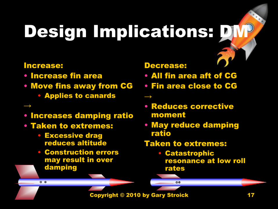
Design Implications: DM
Increase:
• Increase fin area
• Move fins away from CG
• Applies to canards
→
• Increases damping ratio
• Taken to extremes:
• Excessive drag
reduces altitude
• Construction errors
may result in over
damping
Decrease:
• All fin area aft of CG
• Fin area close to CG
→
• Reduces corrective
moment
• May reduce damping
ratio
Taken to extremes:
• Catastrophic
resonance at low roll
rates

Copyright © 2010 by Gary Stroick 18
Design Implications: CM
Increase:
• Increase fin area
• Move fins aft
• Increase Airspeed
→
• Increases oscillation
frequency
• May increase damping ratio
• Decreases disturbance
recovery time
• Taken to extremes:
• Step disturbances will cause
severe weather cocking
(turning into the wind)
• Excessive speeds cause
excessive aerodynamic drag
Decrease:
• Reduce CG/CP
separation
→
• Decreases oscillation
frequency
• Decreases natural
frequency
• Increases damping ratio
Taken to extremes:
• Catastrophic over
damping

Copyright © 2010 by Gary Stroick 19
Design Implications: LM
Increase:
• Add weight fore and aft of CG
• Increase length
→
• Decreases damping ratio &
natural frequency
• More difficult to deflect from
flight path
• Taken to extremes:
• Weight reduces altitude
• Catastrophic resonance at
low roll rates
Decrease:
• Reduce weight fore and aft
• Reduce length
→
• Increases damping ratio &
natural frequency
• Frequent disturbances and
resulting angles of attack will
increase drag & lower altitude
• More easily deflected from
flight path
Taken to extremes:
• Weight reduces altitude
(ballistically below optimum)
• Catastrophic over damping

Copyright © 2010 by Gary Stroick 20
Airframes
Type Strength Weight RF Aging
Effects
Carbon
Fiber
1 4 Opaque Minimal
Aluminum 2 6 Opaque None
Fiberglass 3 5 Transparent
Minimal
Blue Tube 4 3 Transparent
Unknown
Phenolic 5 1 Transparent
Brittle
Quantum
Tube
6 2 Transparent
None
Copyright © 2010 by Gary Stroick 21
Fins
• Parallelograms are effective and easily
produced shapes
• Roll stabilization
• Canted
• Airfoil
• Spinnerons
• Location and size affect DM, CM, and
stability margin
• Fin flutter and divergence undesirable
• Avoid by using stiff materials, thicker fins,
wider fillets, and/or thru the wall designs

Copyright © 2010 by Gary Stroick 22
Nose Cones
• Design Considerations:
• CG adjustments by changing weight
• Recovery harness assembly
− Never use open ended eye bolts!
− Never use plastic attachment points!
• May include electronics or payload
• Seriously consider shear pin retention
• Types: Conical, Ogive, Parabolic,
Elliptical, Power Series, & Sears-Haack
(varying CP, CG, and drag coefficients)

Copyright © 2010 by Gary Stroick 23
Altimeter Bays
• Design Considerations
• Space Availability
• Survivability and Placement of Electronics
• MAD use non-magnetic materials
• Redundancy
• Reusability
• Ease of Use (Accessibility, Assembly, Disassembly)
• Arming and Disarming
• Switches in reachable location (avoid rod/rail)
• Port Placement
• Ports should be away from barometric sensors
• Recovery System
• Dual or single deployment
• Split, aft, or forward deployment
• Ejection method (BP, CO2, Spring) and placement
• Harness attachment points and assembly
− Never use open ended eye bolts! Forged eyes or U bolts.
− Sew together harness or use figure eight/bowline knots (weakest point)

Copyright © 2010 by Gary Stroick 24
Summary:
Design Rules of Thumb
• Motor:
• Thrust to weight ratio - 5:1
• Minimum stable flight speed: 44 feet/sec
• Calm – add 6 ft/sec for every 1 mph
• Airframe:
• Length to diameter ratio – 10-20:1
• Consider anti-zipper designs
• Airframe reinforcement (AL bands, etc)
• Recovery connections points (couplers in airframe, not
altimeter bay, and extended outside airframe)
• Fins:
• Number: ≥ 3
• Fin Root to diameter – 2:1
• Fin Span/Cord to diameter – 1:1

Copyright © 2010 by Gary Stroick 25
Summary:
Design Rules of Thumb
• Recovery
• Recovery Harness to length: 3+:1
• Recovery Harness to weight: 50:1
• Decent Rate: 15-20 feet/sec
• Shear pin number: ≥ 3
• Ejection Charge:
• LBS*Length*.000516=BP grams
− I use 100 lbs but can vary based on diameter
• Don’t use black powder over 20,000 ft unless
enclosed in airtight container
• If using shear pins account for required shear
pin shearing force

Copyright © 2010 by Gary Stroick 26
Summary:
Design Rules of Thumb
• Launch Guides
• Rail Buttons
• Number: ≥ 2
• Location: CG (required) and Aft
• Launch Lugs
• Number: ≥ 1
• Location: CG (required) and Aft

Copyright © 2010 by Gary Stroick 27
Summary:
Design Rules of Thumb
• Altimeter Bay
• Port Number (Pn): ≥ 3
• Port Diameter: πr2l/(400*P
n)
• Vent Holes
• Needed when friction retention is used
• Unnecessary with shear pins (my
opinion)
• Nose Cones
• Optimum Fineness ratio: 5:1
• Shoulder ratio to diameter: 1:1

Copyright © 2010 by Gary Stroick 28
What can happen?

Copyright © 2010 by Gary Stroick 29
References
• Topics in Advanced Model
Rocketry; Mandell, Gordon K.,
Caporaso, George J., Bengen,
William P.; The MIT Press; 1973
• Modern High Power Rocketry 2;
Canepa, Mark; Trafford
Publishing, 2005

Copyright © 2010 by Gary Stroick 30
Selected Websites
• http://exploration.grc.nasa.gov/education/ro
cket/guided.htm
• http://www.apogeerockets.com/Peak-of-
Flight_index.asp
• http://www.info-central.org/
• http://www.rocketmaterials.org/
• http://www.thefintels.com/protected.htm
• http://www.nakka-rocketry.net/
• http://www.arocketry.net/
• http://my.execpc.com/~culp/rockets/Barrow
man.html