ROCK CUT SLOPE STABILITY EVALUATION OF THE...
8
BORNEO SCIENCE 30: MARCH 2012 32 ROCK CUT SLOPE STABILITY EVALUATION OF THE CROCKER FORMATION ALONG JALAN UMS, KOTA KINABALU, SABAH 1* Mohd Muzhafar Mohd Zaki, 1 Sanudin Hj. Tahir, 1 Ismail Abd Rahim, & 2 Ahmad Norazhar Mohd Yatim 1 Geology Programme & 2 Enviromental Science Programme, School of Sciences and Technology, Universiti Malaysia Sabah, Jalan UMS, 88400 Kota Kinabalu, Sabah, Malaysia. ABSTRACT. The aim of this paper is to present the result of an evaluation of the cut rock slope stability of the Crocker Formation along Jalan UMS, Kota Kinabalu, Sabah. Geological mapping, discontinuity survey, and kinematic analysis have been conducted on ten (10) selected cut rock slopes in the study area. Result of kinematic analysis shows that wedge, toppling and planar failures are potential in five cut rock slopes. However, no potential modes of failure are identified in cut rock slopes numbers 2, 7, 8, 9 and 10. Flatten slope range from 30 o to 55 o , wire mesh and drainage ditches are proposed as mitigation measures for the cut rock slopes in the study area. KEYWORDS. Slope stability, crocker formation, Kota Kinabalu, mode of failure, optimum slope angle. INTRODUCTION Slope stability is often the most critical safety issue or feasibility component for quarries, residential developments and road construction in hill slope environments. Slope stability depends largely upon the geologic and geotechnical characteristics of the rock and soil that form the slopes. Not surprisingly, the strength of these materials also plays an important role in slope stability. In rock slopes, often the most important factor of stability is the geologic structure of the rock. Geologic structure refers to the type, condition, orientation, and spacing of discontinuities within the rock mass. Failure usually initiates at and follows pre-existing discontinuities rather than breaking through intact rock. Thus it is the nature of discontinuities and not of the intact rock that governs the mechanical and hydrological behavior of the rock mass (Maerz, 2000).Unforeseen occurrences and damage also depend on the slope morphology and linear infrastructural features. A combination of these factors contribute to the large number of accidents during and after construction work, as well as loss of both material resources and lives (Uribe-Etxebarria et al., 2005). The occurrence of the more than a cubic meter (m 3 ) fallen rock block at the bottom of the cut rock slope at Jalan UMS (Photo1) has become an issue for this study. To ensure the stability of cut rock slope in this area, an evaluation had to be undertaken. To evaluate the rock slope stability, 10 cut rock slopes along Jalan UMS have been selected and identified as Slope 1, 2, 3, 4, 5, 6, 7, 8, 9 and 10. The locations of cut rock slopes in the study area are shown in Figure 1. Generally, the study area is underlain by the Late Eocene to Early Miocene Crocker Formation which is a highly fractured and jointed rock mass. Intense jointing and shearing characterizes the rock mass into polygonal block shapes of various sizes from as small as several cm 3 to up to 10 m 3 (Ismail Abd. Rahim et al., 2009). The rock block type can be classified as tabular rock block and intersection of the major joints gives rise to irregular block type (Ismail Abd. Rahim et al., 2006).
-
Upload
nguyencong -
Category
Documents
-
view
226 -
download
0
Transcript of ROCK CUT SLOPE STABILITY EVALUATION OF THE...
BORNEO SCIENCE 30: MARCH 2012
32
ROCK CUT SLOPE STABILITY EVALUATION OF THE CROCKER FORMATION
ALONG JALAN UMS, KOTA KINABALU, SABAH
1*Mohd Muzhafar Mohd Zaki,
1Sanudin Hj. Tahir,
1Ismail Abd Rahim, &
2Ahmad Norazhar Mohd Yatim
1Geology Programme &
2Enviromental Science Programme,
School of Sciences and Technology,
Universiti Malaysia Sabah, Jalan UMS, 88400 Kota Kinabalu, Sabah, Malaysia.
ABSTRACT. The aim of this paper is to present the result of an evaluation of the cut rock slope
stability of the Crocker Formation along Jalan UMS, Kota Kinabalu, Sabah. Geological mapping,
discontinuity survey, and kinematic analysis have been conducted on ten (10) selected cut rock slopes
in the study area. Result of kinematic analysis shows that wedge, toppling and planar failures are
potential in five cut rock slopes. However, no potential modes of failure are identified in cut rock
slopes numbers 2, 7, 8, 9 and 10. Flatten slope range from 30o to 55
o, wire mesh and drainage ditches
are proposed as mitigation measures for the cut rock slopes in the study area.
KEYWORDS. Slope stability, crocker formation, Kota Kinabalu, mode of failure, optimum slope
angle.
INTRODUCTION
Slope stability is often the most critical safety issue or feasibility component for quarries, residential
developments and road construction in hill slope environments. Slope stability depends largely upon
the geologic and geotechnical characteristics of the rock and soil that form the slopes. Not
surprisingly, the strength of these materials also plays an important role in slope stability.
In rock slopes, often the most important factor of stability is the geologic structure of the rock.
Geologic structure refers to the type, condition, orientation, and spacing of discontinuities within the
rock mass. Failure usually initiates at and follows pre-existing discontinuities rather than breaking
through intact rock. Thus it is the nature of discontinuities and not of the intact rock that governs the
mechanical and hydrological behavior of the rock mass (Maerz, 2000).Unforeseen occurrences and
damage also depend on the slope morphology and linear infrastructural features. A combination of
these factors contribute to the large number of accidents during and after construction work, as well as
loss of both material resources and lives (Uribe-Etxebarria et al., 2005).
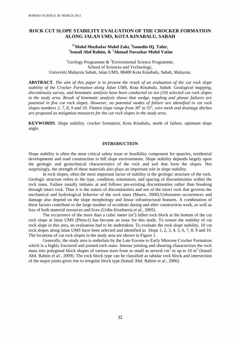
The occurrence of the more than a cubic meter (m3) fallen rock block at the bottom of the cut
rock slope at Jalan UMS (Photo1) has become an issue for this study. To ensure the stability of cut
rock slope in this area, an evaluation had to be undertaken. To evaluate the rock slope stability, 10 cut
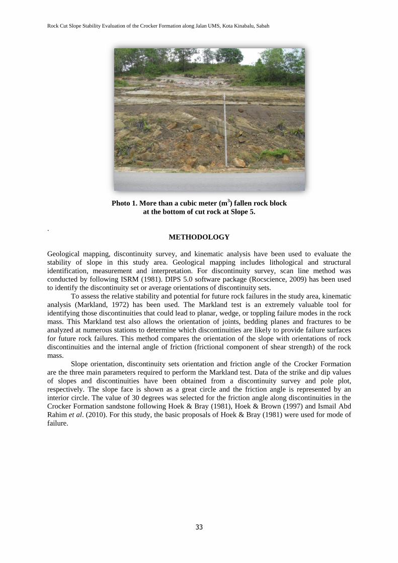
rock slopes along Jalan UMS have been selected and identified as Slope 1, 2, 3, 4, 5, 6, 7, 8, 9 and 10.
The locations of cut rock slopes in the study area are shown in Figure 1.
Generally, the study area is underlain by the Late Eocene to Early Miocene Crocker Formation
which is a highly fractured and jointed rock mass. Intense jointing and shearing characterizes the rock
mass into polygonal block shapes of various sizes from as small as several cm3 to up to 10 m
3 (Ismail
Abd. Rahim et al., 2009). The rock block type can be classified as tabular rock block and intersection
of the major joints gives rise to irregular block type (Ismail Abd. Rahim et al., 2006).
Rock Cut Slope Stability Evaluation of the Crocker Formation along Jalan UMS, Kota Kinabalu, Sabah
33
Photo 1. More than a cubic meter (m3) fallen rock block
at the bottom of cut rock at Slope 5.
.
METHODOLOGY
Geological mapping, discontinuity survey, and kinematic analysis have been used to evaluate the
stability of slope in this study area. Geological mapping includes lithological and structural
identification, measurement and interpretation. For discontinuity survey, scan line method was
conducted by following ISRM (1981). DIPS 5.0 software package (Rocscience, 2009) has been used
to identify the discontinuity set or average orientations of discontinuity sets.
To assess the relative stability and potential for future rock failures in the study area, kinematic
analysis (Markland, 1972) has been used. The Markland test is an extremely valuable tool for
identifying those discontinuities that could lead to planar, wedge, or toppling failure modes in the rock
mass. This Markland test also allows the orientation of joints, bedding planes and fractures to be
analyzed at numerous stations to determine which discontinuities are likely to provide failure surfaces
for future rock failures. This method compares the orientation of the slope with orientations of rock
discontinuities and the internal angle of friction (frictional component of shear strength) of the rock
mass.
Slope orientation, discontinuity sets orientation and friction angle of the Crocker Formation
are the three main parameters required to perform the Markland test. Data of the strike and dip values
of slopes and discontinuities have been obtained from a discontinuity survey and pole plot,
respectively. The slope face is shown as a great circle and the friction angle is represented by an
interior circle. The value of 30 degrees was selected for the friction angle along discontinuities in the
Crocker Formation sandstone following Hoek & Bray (1981), Hoek & Brown (1997) and Ismail Abd
Rahim et al. (2010). For this study, the basic proposals of Hoek & Bray (1981) were used for mode of
failure.
Mohd Muzhafar Mohd Zaki, SanudinHj. Tahir, Ismail Abd Rahim, & Ahmad Norazhar Mohd Yatim
34
Figure 1. Location of cut rock slopes and geological map of the study area.
Rock Cut Slope Stability Evaluation of the Crocker Formation along Jalan UMS, Kota Kinabalu, Sabah
35
RESULTS
Evaluation of rock slope stability was performed by kinematic analyses. Kinematic refers to the
motion of bodies without reference to the forces that cause them to move (Goodman, 1989). A
kinematic analysis is very useful to investigate possible failure modes of rock masses which contain
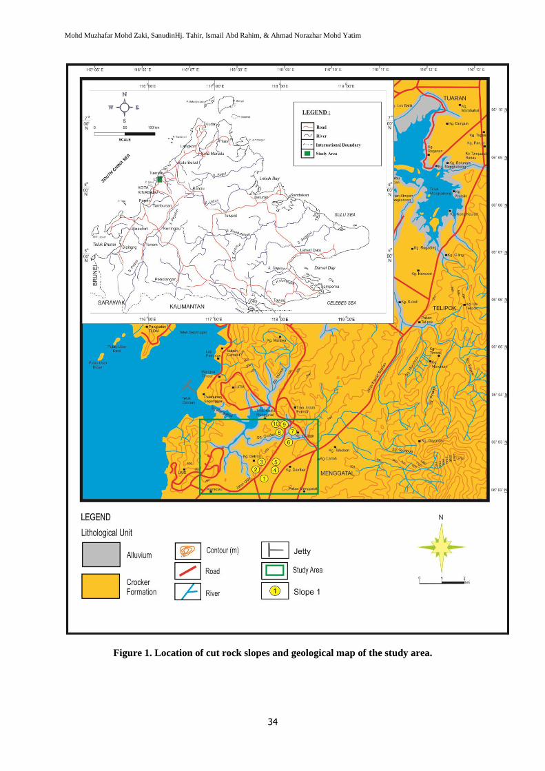
discontinuities (Jeongi-gi Um & Kulatilake, 2001).The results of kinematic analyses of each cut slope
are shown in Figure 2 and Table 1.
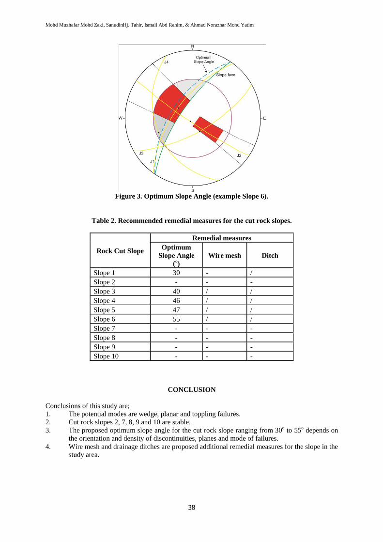
From the kinematic analyses, the optimum slope angle for each cut slope was determined by
considering the safest slope angle for any type of failure. The basic concepts related to estimation of
optimum safe slope angles for the three basic modes of failure are discussed by Goodman (1989) and
Ismail Abd Rahim et al., (2006, 2010). Example of the identification of optimum slope angle for Slope
6 is shown in Figure 3. Other remedial measures for each cut slope were considered during the
kinematic check and are shown in summary are in Table 2.
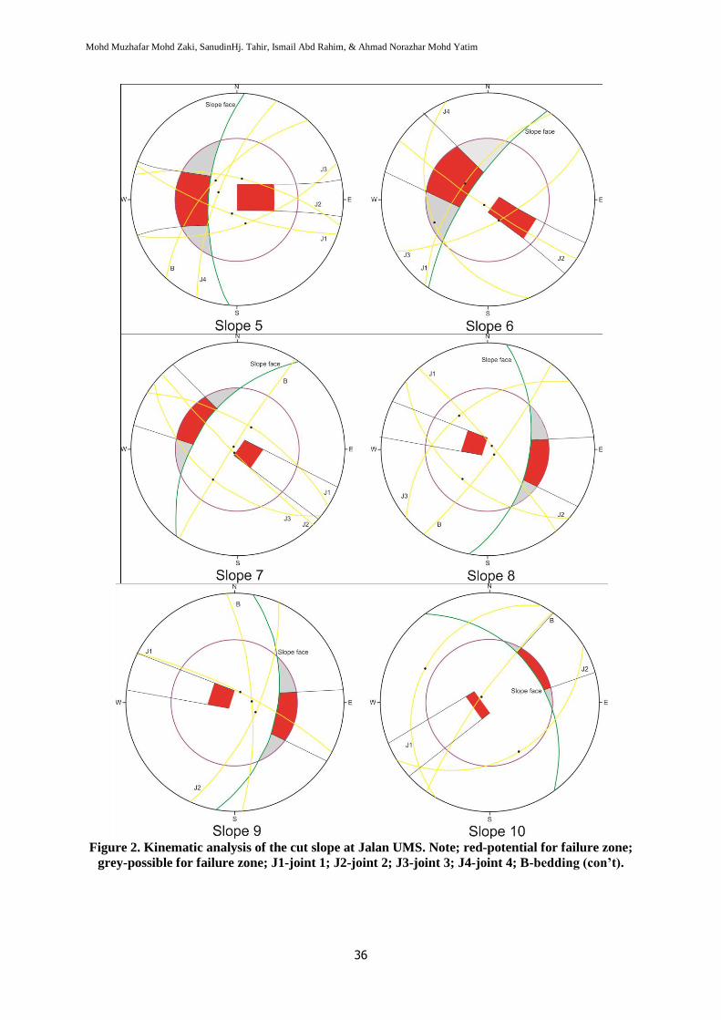
Figure 2. Kinematic analysis of the cut slope at Jalan UMS. Notes: red-potential failure zone;
grey-possible failure zone; J1-joint 1; J2-joint 2; J3-joint 3; J4-joint 4; B-bedding.
Mohd Muzhafar Mohd Zaki, SanudinHj. Tahir, Ismail Abd Rahim, & Ahmad Norazhar Mohd Yatim
36
Figure 2. Kinematic analysis of the cut slope at Jalan UMS. Note; red-potential for failure zone;
grey-possible for failure zone; J1-joint 1; J2-joint 2; J3-joint 3; J4-joint 4; B-bedding (con’t).
Rock Cut Slope Stability Evaluation of the Crocker Formation along Jalan UMS, Kota Kinabalu, Sabah
37
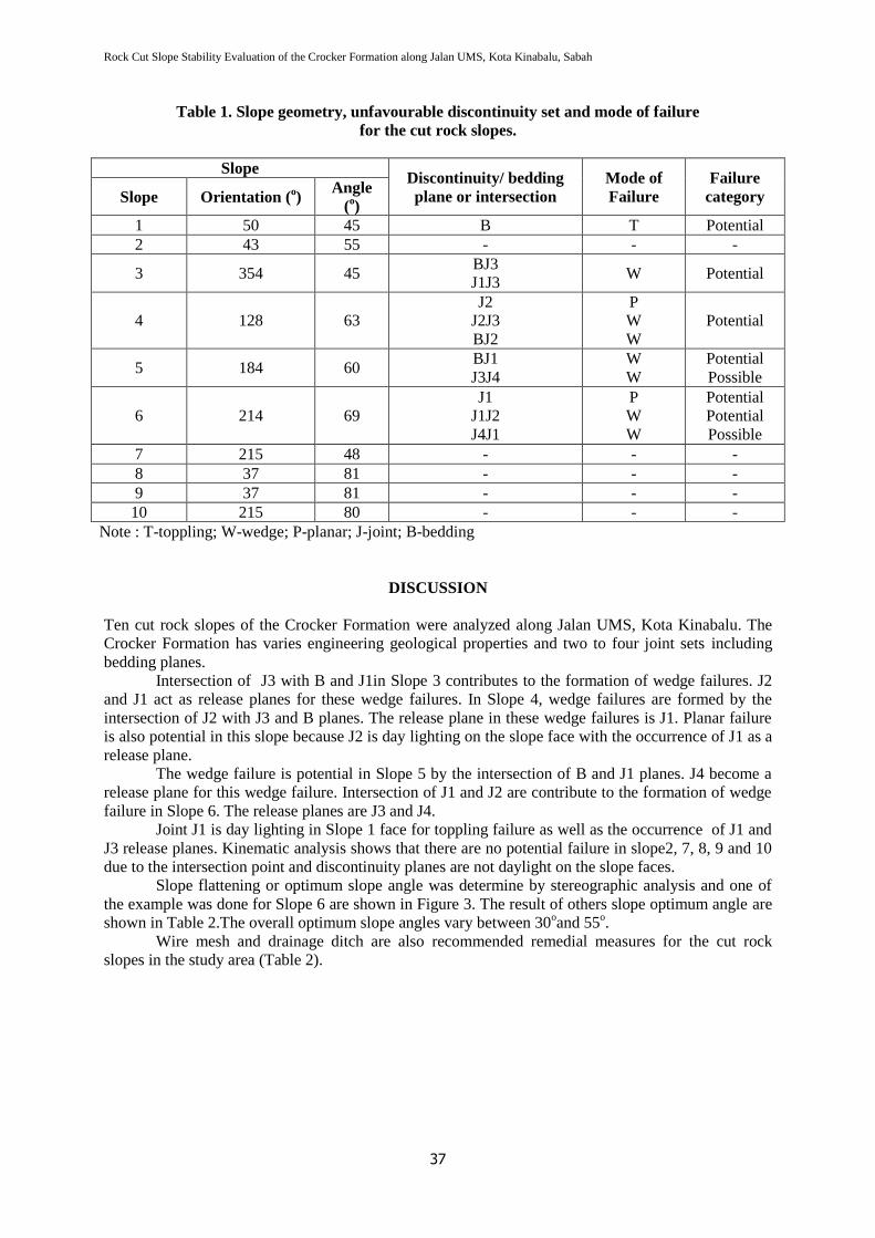
Table 1. Slope geometry, unfavourable discontinuity set and mode of failure
for the cut rock slopes.
Slope Discontinuity/ bedding
plane or intersection
Mode of
Failure
Failure
category Slope Orientation (o)
Angle
(o)
1 50 45 B T Potential
2 43 55 - - -
3 354 45 BJ3
J1J3 W Potential
4 128 63
J2
J2J3
BJ2
P
W
W
Potential
5 184 60 BJ1
J3J4
W
W
Potential
Possible
6 214 69
J1
J1J2
J4J1
P
W
W
Potential
Potential
Possible
7 215 48 - - -
8 37 81 - - -
9 37 81 - - -
10 215 80 - - -
Note : T-toppling; W-wedge; P-planar; J-joint; B-bedding
DISCUSSION
Ten cut rock slopes of the Crocker Formation were analyzed along Jalan UMS, Kota Kinabalu. The
Crocker Formation has varies engineering geological properties and two to four joint sets including
bedding planes.
Intersection of J3 with B and J1in Slope 3 contributes to the formation of wedge failures. J2
and J1 act as release planes for these wedge failures. In Slope 4, wedge failures are formed by the
intersection of J2 with J3 and B planes. The release plane in these wedge failures is J1. Planar failure
is also potential in this slope because J2 is day lighting on the slope face with the occurrence of J1 as a
release plane.
The wedge failure is potential in Slope 5 by the intersection of B and J1 planes. J4 become a
release plane for this wedge failure. Intersection of J1 and J2 are contribute to the formation of wedge
failure in Slope 6. The release planes are J3 and J4.
Joint J1 is day lighting in Slope 1 face for toppling failure as well as the occurrence of J1 and
J3 release planes. Kinematic analysis shows that there are no potential failure in slope2, 7, 8, 9 and 10
due to the intersection point and discontinuity planes are not daylight on the slope faces.
Slope flattening or optimum slope angle was determine by stereographic analysis and one of
the example was done for Slope 6 are shown in Figure 3. The result of others slope optimum angle are
shown in Table 2.The overall optimum slope angles vary between 30oand 55
o.
Wire mesh and drainage ditch are also recommended remedial measures for the cut rock
slopes in the study area (Table 2).
Mohd Muzhafar Mohd Zaki, SanudinHj. Tahir, Ismail Abd Rahim, & Ahmad Norazhar Mohd Yatim
38
Figure 3. Optimum Slope Angle (example Slope 6).
Table 2. Recommended remedial measures for the cut rock slopes.
Rock Cut Slope
Remedial measures
Optimum
Slope Angle
(o)
Wire mesh Ditch
Slope 1 30 - /
Slope 2 - - -
Slope 3 40 / /
Slope 4 46 / /
Slope 5 47 / /
Slope 6 55 / /
Slope 7 - - -
Slope 8 - - -
Slope 9 - - -
Slope 10 - - -
CONCLUSION
Conclusions of this study are;
1. The potential modes are wedge, planar and toppling failures.
2. Cut rock slopes 2, 7, 8, 9 and 10 are stable.
3. The proposed optimum slope angle for the cut rock slope ranging from 30o to 55
o depends on
the orientation and density of discontinuities, planes and mode of failures.
4. Wire mesh and drainage ditches are proposed additional remedial measures for the slope in the
study area.
Rock Cut Slope Stability Evaluation of the Crocker Formation along Jalan UMS, Kota Kinabalu, Sabah
39
REFERENCES
Goodman, R. E. 1989. Introduction to Rock Mechanics. 2nd
ed. John Wiley & Son, New York.
Hoek, E. & Bray, J. W. 1981. Rock Slope Engineering. 3rd
ed. Institution of Mining and Metallurgy,
London, 359pp.
Hoek, E. & Brown, E. T. 1997. Practical Estimate of Rock Mass Strength. International Journal of
rock Mechanics & Mining Sciences Geomechanics Abstract, 34 (8): 1165-1186.
ISRM, 1981. Rock Characterization, Testing and Monitoring. In: Brown, E.T. (Ed.). International
Society for Rock Mechanics (ISRM) Suggested Methods. Pergamon, Oxford. 211 pp.
Ismail Abd. Rahim, Sanudin Haji Tahir, Baba Musta, & Rodeano Roslee. 2006. Slope Stability
Assessment of the Crocker Formation in the Telipok, Sabah. Proceeding of the Southeast
Asian Natural Resources and Environmental Management Conference (SANREM 2006).21-22
November 2006, Le Meridian Hotel, Kota Kinabalu.
Ismail Abd Rahim, Sanudin Tahir, & Baba Musta. 2009. Modified Slope Mass Rating (M-SMR)
System: A Classification Scheme of Interbedded Crocker Formation in Kota Kinabalu, Sabah,
Malaysia. Proceeding of the 8th Seminar on Science and Technology 2009 (S&T2009), 18-19
December 2009, Shangri-La’s Rasa Ria Resort, Pantai Dalit, Tuaran.
Ismail Abd Rahim, Sanudin Tahir, Baba Musta, & Shariff A. K. Omang. 2010. Slope Stability
Evaluation of Selected Rock Cut Slope of Crocker Formation in Kota Kinabalu, Sabah.
Proceeding of the 3rd Southeast Asian Natural Resources and Environmental Management
(SANREM 2010), 3-5 August 2010, Promenade Hotel, Kota Kinabalu, Sabah.
Jeongi-gi Um & Kulatilake, P. H. S. W. 2001. Kinematic and Block Theory Analysis for Shiplock
Slope of the Three Gorges Dam Site in China. Geotechnical and Geological Engineering, 19:
21-42.
Maerz, N. H. 2000. Highway Rock Cut Stability Assessment in Rock Masses not Conducive to
Stability Calculations. Proceeding of the 51st Annual Highway Symposium, Seattle,
Washington, 29 August-1 September 2000: 249-259.
Markland, J. T. 1972. A Useful Technique for Estimating the Stability of Rock Slopes when the Rigid
Wedge Slide Type of Failure is Expected. Imperial College Rock Mechanics Research reprint,
n. 19.
Uribe-Etxebarria G, Morales T, Uriarte JA, Ibarra V. 2005. Rock Cut Stability Assessment in
Mountainous Regions. Environmental Geology, 48 (8): 1002–1013.
Rocscience. 2009. Dips 5.0 Graphical & Statistical Analysis of Orientation Data©2009. Rocscience
Inc. http://www.rocscience.com.