Rocie Benavent Chelseyann Bipat Brandon Gilyard...
22
AENG 360 – Aerodynamics Investigation and Comparison of Airfoils Rocie Benavent Chelseyann Bipat Brandon Gilyard Julian Marcon New York Institute of Technology Fall 2013
Transcript of Rocie Benavent Chelseyann Bipat Brandon Gilyard...
AENG 360 – Aerodynamics
Investigation and Comparison of Airfoils
Rocie Benavent
Chelseyann Bipat
Brandon Gilyard
Julian Marcon
New York Institute of Technology
Fall 2013
2
Executive Summary Airfoil design has gone through a major progression within the history of flight, and it
has been with that progression that advances have been able to contribute to improved stability,
reduction in undesirable parameters, and ability to trade-off between previous and current
designs. This project dealt with taking an original airfoil−that of the Piper Warrior II PA-28-
161−and comparing it to the NACA 2412 airfoil. Originally, the assigned case was a Piper
Archer II that utilized the same airfoil (NACA 652-615) so therefore, another airfoil that was
used with the Cessna 172K was chosen (NACA 2412). This was because of the fact that the
Cessna 172K has a similar horsepower and passenger capacity and weight, and therefore, is a
suitable choice for analyzing the effect of swapping airfoils. Within the scope of Theory of Wing
Sections by Abbott and Von Doenhoff, Jane’s All the World’s Aircraft, and other scholastic
journals, the wing comparisons focused on the following: operating range parameters, wing
loading requirements, airfoil profiles, lift coefficients and angles of attack, drag polars, design
lift coefficients, maximum L/D, and the respective NACA designations. The entire comparison
and trade-off analyses processes consisted of calculating both airfoil lift coefficients for the plane
speeds obtained from their respective references; determining the range in angle of attack for
those speeds; discussing trading off the original airfoil with the alternate; analyzing the changing
of angle of incidence, dihedral, and angle of twist; addressing how 3D flow relates to the
aforementioned topics; and utilizing Design Foil (an aerodynamics software package) to show
effects of increased thickness and camber on the original wing.
Ultimately, it is seen that the comparison yields an unfavorable result. It is not wise to
replace the original NACA 65-415 airfoil with the NACA 2412 as a decrease in lift and increase
and drag were obtained. Even though the designs are valid for aircraft of a similar variety, the
numbers for the sections chosen are not valid.
3
Table of Contents Executive Summary ...............................................................................................................2
Part 1 ......................................................................................................................................4
Introduction/Problem Statement .......................................................................................4
Description of Selected Wings..........................................................................................5
Describe NACA information and all available data for both wings .................................12
Part 2 ......................................................................................................................................13
1. Airfoil Lift Coefficients ................................................................................................13
2. Range in Angles of Attack ............................................................................................13
3. Replacing the original airfoil with the alternate ...........................................................14
4. Change in the Angle of Incidence Effects ....................................................................16
5. Change in the Dihedral or Angle of Twist Benefits .....................................................16
6. For 3, show how 3D flow (airfoil vs wing) changes the above results .........................17
7. DesignFoil simulation of increased camber and thickness ...........................................19
References ..............................................................................................................................22
4
Part 1
Introduction/Problem Statement
Since the advent of the first plane successfully flown by the Wright brothers, all aviation
aircraft have continued to advance in areas such as performance, efficiency, range, and material
constituents−just to name a few. Airplane design has been a process that examines several
parameters, characteristics, and adherence to stringent requirements. These categories have
focused on, but have not been limited to: cruise speed, take-off speed, landing speed, stall speed,
glide speed; aerodynamic efficiency and altitude limitations, take-off and landing distances,
power and wing loading, airfoil profiles, lift coefficients and associate angles of attack, drag
polars, Lift to Drag (L/D) maximums, and NACA profile designations. The aforementioned
factors, and their relations to all types of aircraft, have had a high influence on the improvements
on future designs as a result of comparisons.
Wing selection is one of the most important steps in the design of an airplane. After
deciding the basic design configurations such as overall weight, size, capacity, flying range
comes the choice of an effective airfoil profile for the airplane in process of design. There are
now a vast amount of different profiles - NACA series being among the most famous and widely
used ones - that differ in many parameters. The first aspect that should be considered when
selecting a wing profile is the type of airplane that is being designed. Indeed, different airplane
types such as commercial transport jets, fighter jets, propeller-driven airplanes or even gliders
will have wings with significant differences in their aerodynamic properties. These properties are
affected by basic airfoil parameters such as chord length, thickness, and camber. Following basic
airfoil parameters, other factors affect the aerodynamic forces applied to the tridimensional wing.
These include angle of attack, angle of incidence, taper ratio, and dihedral angle among others.
This project aims to compare two different airfoils in terms of aerodynamic properties.
These properties will first be identified from official references and compared for an accurate
overview of the problem. Then, analyses will be made and pros and cons discussed about the
possibility of replacing the original airfoil with the newer one. Main improvements are sought in
increase of lift coefficient and decrease of drag coefficient for better overall aerodynamic
efficiency. Further implications of this change of wing profile will also be discussed as well as
5
other possibility modifications such as a change in angles of incidence and of twist and dihedral
angle. Finally, educational airfoil simulation software such as DesignFoil will be used to identify
the results of additional modifications to the wing profile such as increased camber and
thickness.
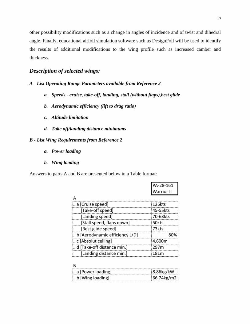
Description of selected wings:
A - List Operating Range Parameters available from Reference 2
a. Speeds - cruise, take-off, landing, stall (without flaps),best glide
b. Aerodynamic efficiency (lift to drag ratio)
c. Altitude limitation
d. Take off/landing distance minimums
B - List Wing Requirements from Reference 2
a. Power loading
b. Wing loading
Answers to parts A and B are presented below in a Table format:
2
6
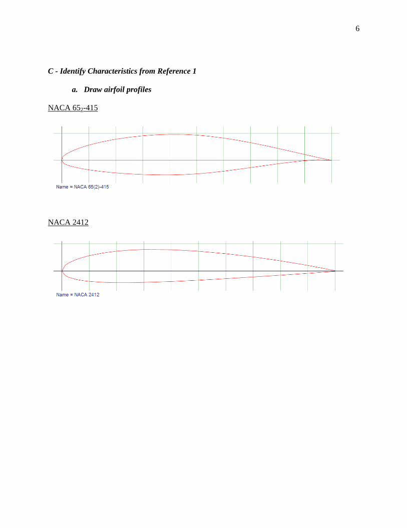
C - Identify Characteristics from Reference 1
a. Draw airfoil profiles
NACA 652-415
NACA 2412
7
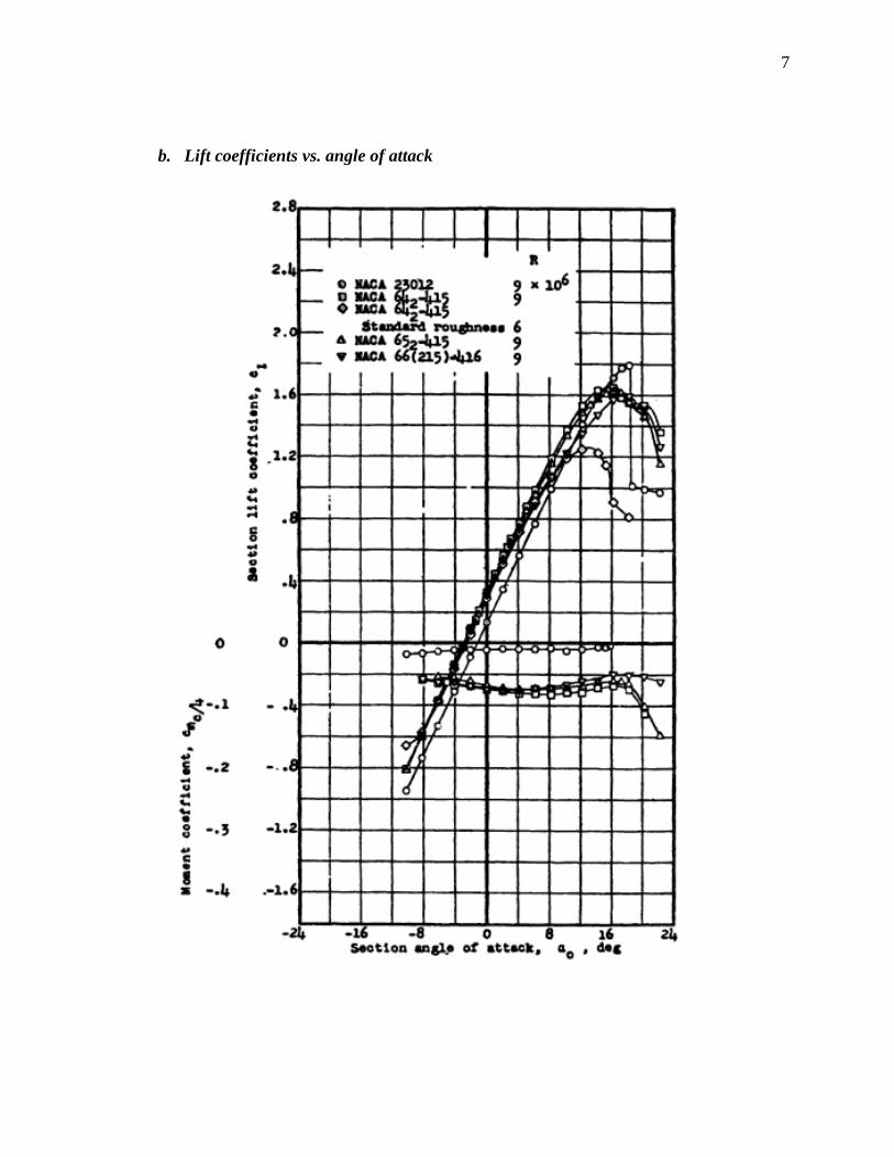
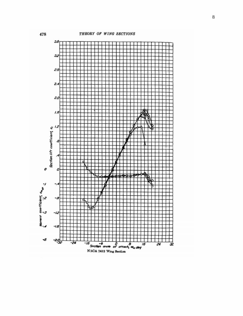
b. Lift coefficients vs. angle of attack
8
9
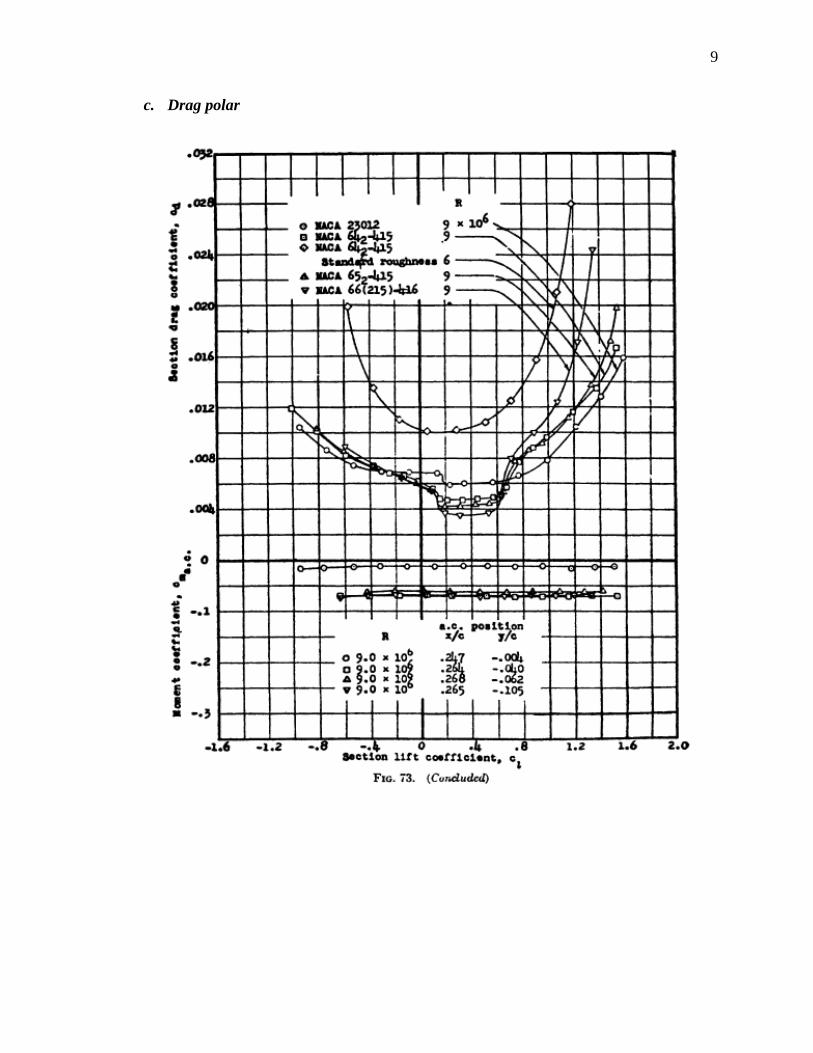
c. Drag polar
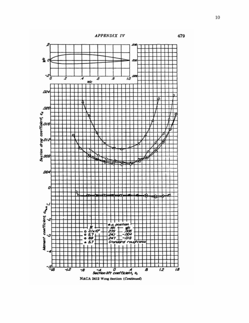
10
11
d. Design lift coefficient
From the NACA 6-series notation described below, the design lift coefficient is indicated by the
first digit after the hyphen, in tenths. The wing used is NACA 652-415, therefore 4/10 = 0.4.
Design lift coefficient = 0.4
e. Maximum L/D
From the drag polar graph for NACA 65-415, this occurs at the point Cl=0.6, and
Cd=0.0042. The max L/D at this point is 142.5.
From the drag polar graph for NACA 2412, this occurs at the point Cl=1.1, and Cd=0.009.
The max L/D at this point is 122.2.
This is one of the most important aspect of considering whether or not the airfoil is
suitable because this is the lift coefficient at the best glide speed, which is when it is most
important to evaluate whether or not the airfoil will be effective at all. It is also important to note
that the best glide speed for both aircrafts are taken from the pilot’s operating handbook. It
should also be noted that because of this, this includes the lift and drag included with the
empennage and fuselage of the airplane.
f. NACA or other profile designation - explain
NACA 652-415. This new series shows an improvement over 1-series airfoils with
emphasis on maximizing laminar flow. The airfoil is described using six digits in the following
sequence:
1. The number "6" indicating the series.
2. One digit describing the distance of the minimum pressure area in tens of percent of chord.
3. The subscript digit gives the range of lift coefficient in tenths above and below the design lift
coefficient in which favorable pressure gradients exist on both surfaces
4. A hyphen.
5. One digit describing the design lift coefficient in tenths.
6. Two digits describing the maximum thickness as percent of chord.
12
NACA 2412. The NACA four-digit wing sections define the profile by:
1. First digit describing maximum camber as percentage of the chord.
2. Second digit describing the distance of maximum camber from the airfoil leading edge in tens
of percent of the chord.
3. Last two digits describing maximum thickness of the airfoil as percent of the chord.
Describe NACA information and all available data for both wings
Piper Warrior II PA-28-161
Wing and Power Loading
The Piper Warrior II, which features tapered wings, is quite the capable aircraft. The
wing requirements, as stated in Reference 2, for both maximum wing and maximum power
loading are 66.74 kg/m2 or 13.67 lb/sq∙ft, and 8.86 kg/kW or 14.53 lb/hp, respectively.
Other Wing Data
The associated areas for wings, ailerons, trailing-edge flaps, fin, rudder, and tailplane, of
the Warrior II are: 15.8 m2, 1.23 m2, 1.36 m2, 0.69 m2, 0.38 m2, and 2.46 m2, respectively. The
wing span, as stated in Reference 2, is 10.67 m (35 ft); the wing chord at the root and tip are 1.60
and 1.07 m respectively; the aspect ratio is 7.24; the overall length and height are 7.25 m and
2.22 m respectively; the tailplane span is 3.96; the wheel track and wheelbase are 3.05 m and
2.03 m respectively; the propeller diameter and ground clearance are 1.88 m and 0.21 m
respectively; and the cabin door height and width are 0.89 and 0.91 m respectively.
Maximum Speeds
The maximum take-off speed and optimum power cruising speed at 2,745 rpms of the
Warrior is 127 knots; the best power cruising speeds at 65 percent and 55 percent, are 118 knots
and 107 knots at 12,500 ft, respectively.
Length Attributes/Capabilities
In reference to Abbott and Von Doenhoff, the absolute ceiling and landing run for the
Warrior II is 4,600m and 181m respectively.
13
Part 2
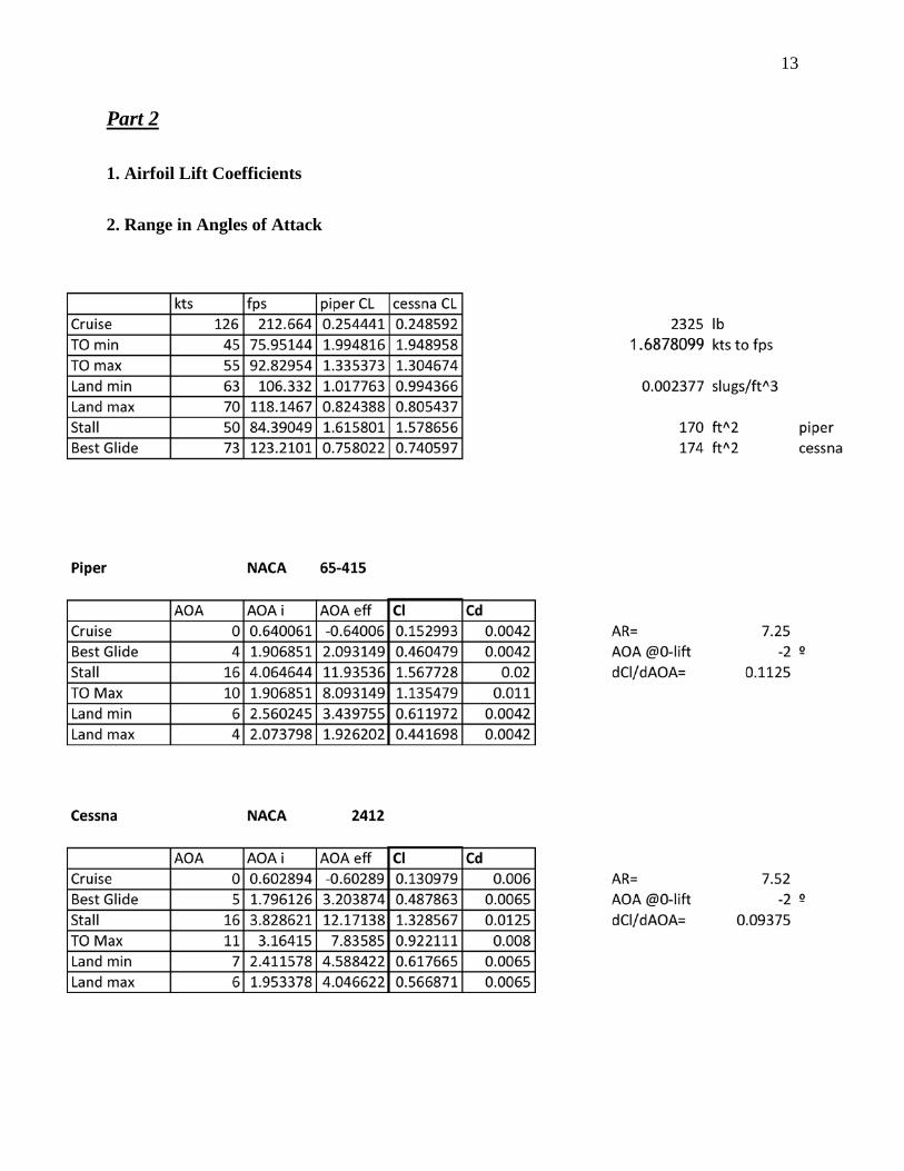
1. Airfoil Lift Coefficients
2. Range in Angles of Attack
14
Piper wing – NACA 652-415
From the drag polar graph for NACA 652-415, this occurs at the point Cl=0.6, and Cd=0.0042.
The max L/D at this point is 142.5. For NACA 652-415 airfoil, angle of attack = 2 degrees.
CL @ TO min will be achievable by using less than max take off weight.
Highest angle of attack @ stall – 16 degrees
Angle of attack @ cruise – 0 degrees
Range – min Cl (cruise) = 0.0045, stall cd =0.02
Best glide – for Cl = 0.75, Cd =0.008, AOA = 4 deg
Cessna wing – NACA 2412
At least roughness – CL = 1.7 at stall at 16 degrees AOA
Cruise – AOA 0 degrees, min Cl = 0.006
Stall Cd = 0.019
Best glide - for Cl = 0.75, Cd=0.0075, AOA= 5 deg
Comparison
At stall, there is less drag associated with the NACA 2412, but at cruise speed, there is
more drag with NACA 2412 than with NACA 652-415. The angles of attack are at the same
range (0-16 degrees), and the drag coefficients at stall are approximately equal (0.02).
3. Replacing the original airfoil with the alternate
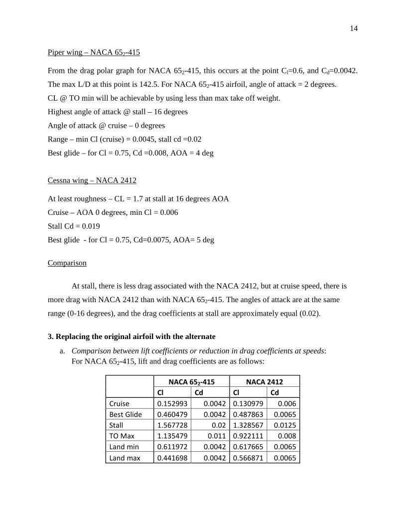
a. Comparison between lift coefficients or reduction in drag coefficients at speeds: For NACA 652-415, lift and drag coefficients are as follows:
NACA 652-415 NACA 2412
Cl Cd Cl Cd Cruise 0.152993 0.0042 0.130979 0.006 Best Glide 0.460479 0.0042 0.487863 0.0065 Stall 1.567728 0.02 1.328567 0.0125 TO Max 1.135479 0.011 0.922111 0.008 Land min 0.611972 0.0042 0.617665 0.0065 Land max 0.441698 0.0042 0.566871 0.0065
15
It can be seen that replacing the NACA 652-415 airfoil with the NACA 2412 airfoil
results in a decrease in lift, and an increase in drag. This shows that the NACA 2412
airfoil is not an ideal replacement for the NACA 652-415, even though that both wings
are ideally designed for similar aircraft type.
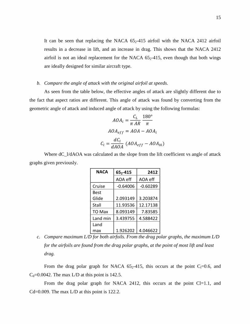
b. Compare the angle of attack with the original airfoil at speeds.
As seen from the table below, the effective angles of attack are slightly different due to
the fact that aspect ratios are different. This angle of attack was found by converting from the
geometric angle of attack and induced angle of attack by using the following formulas:
𝐴𝑂𝐴𝑖 =𝐶𝐿𝜋 𝐴𝑅
180°𝜋
𝐴𝑂𝐴𝑒𝑓𝑓 = 𝐴𝑂𝐴 − 𝐴𝑂𝐴𝑖
𝐶𝑙 =𝑑𝐶𝑙𝑑𝐴𝑂𝐴
(𝐴𝑂𝐴𝑒𝑓𝑓 − 𝐴𝑂𝐴0𝑙)
Where dC_l/dAOA was calculated as the slope from the lift coefficient vs angle of attack
graphs given previously.
NACA 652-415 2412 AOA eff AOA eff
Cruise -0.64006 -0.60289 Best Glide 2.093149 3.203874 Stall 11.93536 12.17138 TO Max 8.093149 7.83585 Land min 3.439755 4.588422 Land max 1.926202 4.046622
c. Compare maximum L/D for both airfoils. From the drag polar graphs, the maximum L/D
for the airfoils are found from the drag polar graphs, at the point of most lift and least
drag.
From the drag polar graph for NACA 652-415, this occurs at the point Cl=0.6, and
Cd=0.0042. The max L/D at this point is 142.5.
From the drag polar graph for NACA 2412, this occurs at the point Cl=1.1, and
Cd=0.009. The max L/D at this point is 122.2.

16
d. Discuss implications of airfoil cross sectional area change.
The most important effect that increased camber has on the original airfoil is increased
lift at almost all angles of attack. The only exception is the NACA 7412, which features a
maximum camber of 7% the chord length. The reason might be that transition between laminar
and turbulent flow over the airfoil occurs so early that, although not at stall yet, it is not able to
produce more lift at high angles of attack.
Another effect, which is negligible at small camber but becomes important at large
camber, is an increased drag at low lift coefficient and therefore low angles of attack. This means
that, if only little is required, the drag will be more important because of the increased camber. In
other words, increased camber should be used on airfoils only when high lift is required.
A last effect is the increased moment coefficient, which is to be taken in account when designing
the wing internal structure.
4. Change in the Angle of Incidence Effects
The angle of incidence, unlike its close relative−the angle of attack− is the angle that is
formed between the wing’s chord line and the lengthwise axis of the aircraft plane or that of the
fuselage. Suffice it to say, that the angle of attack is representative of the angle between the
chord of the airfoil/wing and that of the airflow direction. A change in the angle of incidence
(which is usually a fixed parameter) would most certainly change the angle of attack. This
would resultantly adjust the lift that is generated by the airfoil as well as the coefficient of lift.
5. Change in the Dihedral or Angle of Twist Benefits
On the other hand, the involvement of the dihedral or angle of twist consists of a bit more
analysis in relation to the benefits therein. It is to be duly noted that there is a distinctive
difference between a dihedral and angle of twist. But, it is also appropriate to know that there
exists both aerodynamic and geometric twist. Geometric twist relates to the physical change in
the airfoil’s angle of incident from the root, and the notion of the airfoil washing out as one
would move away from the fuselage. Similarly, the aerodynamic twist represents the angle
amongst the angle of zero lift for an airfoil section as well as the angle of zero lift at the
17
respective root. Thus, changing the angle of twist allows for the outer section of the wing avoid
imminent stall. This is simply due to the reduction in angle of attack in the respective outboard
region. Whereas the twist is in and of itself a beneficial parameter, the dihedral purports a
similar tactic. This tactic, however, is quite dependent on center of gravity, wing sweep, and any
other component that affects the roll stability. If an aircraft is pictured from its front or nose, the
dihedral would be, “the upward angle of the wing from the vertical. For instance, as Jackson’s
Wing Twist and Dihedral, “If each wing is angled 5° up from the horizontal, then the wind is
said to have 5° of dihedral” (Jackson 3). The dihedral simply provides stability and an increase
in lift for an airfoil/aircraft that may be experiencing yawing or rolling moments.
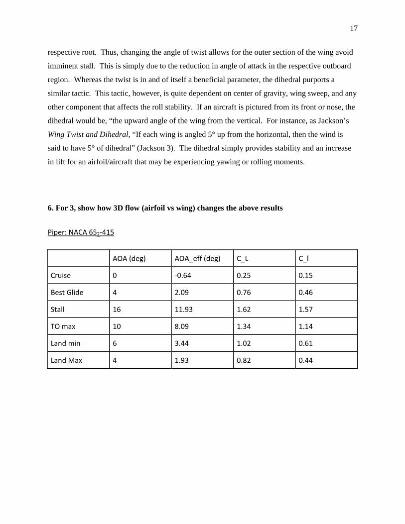
6. For 3, show how 3D flow (airfoil vs wing) changes the above results
Piper: NACA 652-415
AOA (deg) AOA_eff (deg) C_L C_l
Cruise 0 -0.64 0.25 0.15
Best Glide 4 2.09 0.76 0.46
Stall 16 11.93 1.62 1.57
TO max 10 8.09 1.34 1.14
Land min 6 3.44 1.02 0.61
Land Max 4 1.93 0.82 0.44
18
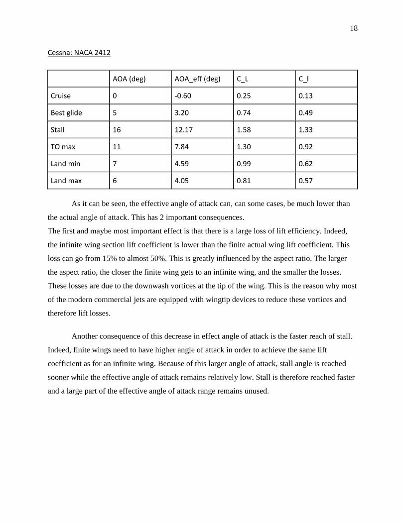
Cessna: NACA 2412
AOA (deg) AOA_eff (deg) C_L C_l
Cruise 0 -0.60 0.25 0.13
Best glide 5 3.20 0.74 0.49
Stall 16 12.17 1.58 1.33
TO max 11 7.84 1.30 0.92
Land min 7 4.59 0.99 0.62
Land max 6 4.05 0.81 0.57
As it can be seen, the effective angle of attack can, can some cases, be much lower than
the actual angle of attack. This has 2 important consequences.
The first and maybe most important effect is that there is a large loss of lift efficiency. Indeed,
the infinite wing section lift coefficient is lower than the finite actual wing lift coefficient. This
loss can go from 15% to almost 50%. This is greatly influenced by the aspect ratio. The larger
the aspect ratio, the closer the finite wing gets to an infinite wing, and the smaller the losses.
These losses are due to the downwash vortices at the tip of the wing. This is the reason why most
of the modern commercial jets are equipped with wingtip devices to reduce these vortices and
therefore lift losses.
Another consequence of this decrease in effect angle of attack is the faster reach of stall.
Indeed, finite wings need to have higher angle of attack in order to achieve the same lift
coefficient as for an infinite wing. Because of this larger angle of attack, stall angle is reached
sooner while the effective angle of attack remains relatively low. Stall is therefore reached faster
and a large part of the effective angle of attack range remains unused.
19
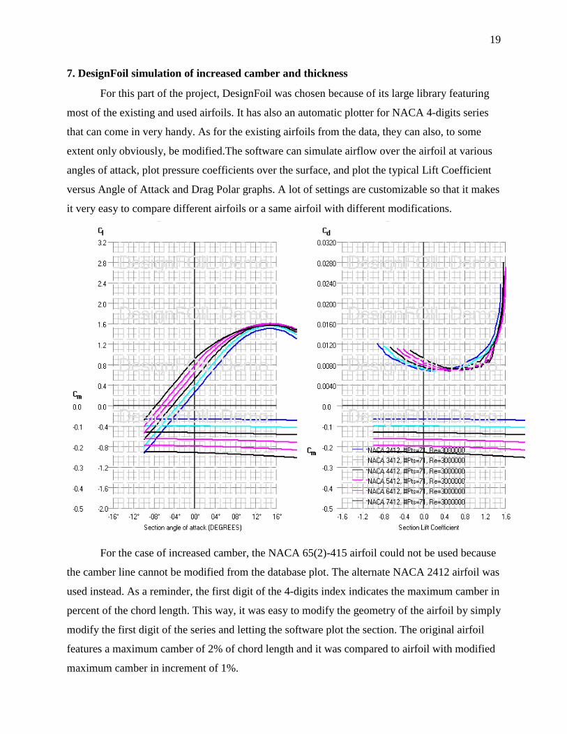
7. DesignFoil simulation of increased camber and thickness
For this part of the project, DesignFoil was chosen because of its large library featuring
most of the existing and used airfoils. It has also an automatic plotter for NACA 4-digits series
that can come in very handy. As for the existing airfoils from the data, they can also, to some
extent only obviously, be modified.The software can simulate airflow over the airfoil at various
angles of attack, plot pressure coefficients over the surface, and plot the typical Lift Coefficient
versus Angle of Attack and Drag Polar graphs. A lot of settings are customizable so that it makes
it very easy to compare different airfoils or a same airfoil with different modifications.
For the case of increased camber, the NACA 65(2)-415 airfoil could not be used because
the camber line cannot be modified from the database plot. The alternate NACA 2412 airfoil was
used instead. As a reminder, the first digit of the 4-digits index indicates the maximum camber in
percent of the chord length. This way, it was easy to modify the geometry of the airfoil by simply
modify the first digit of the series and letting the software plot the section. The original airfoil
features a maximum camber of 2% of chord length and it was compared to airfoil with modified
maximum camber in increment of 1%.
20
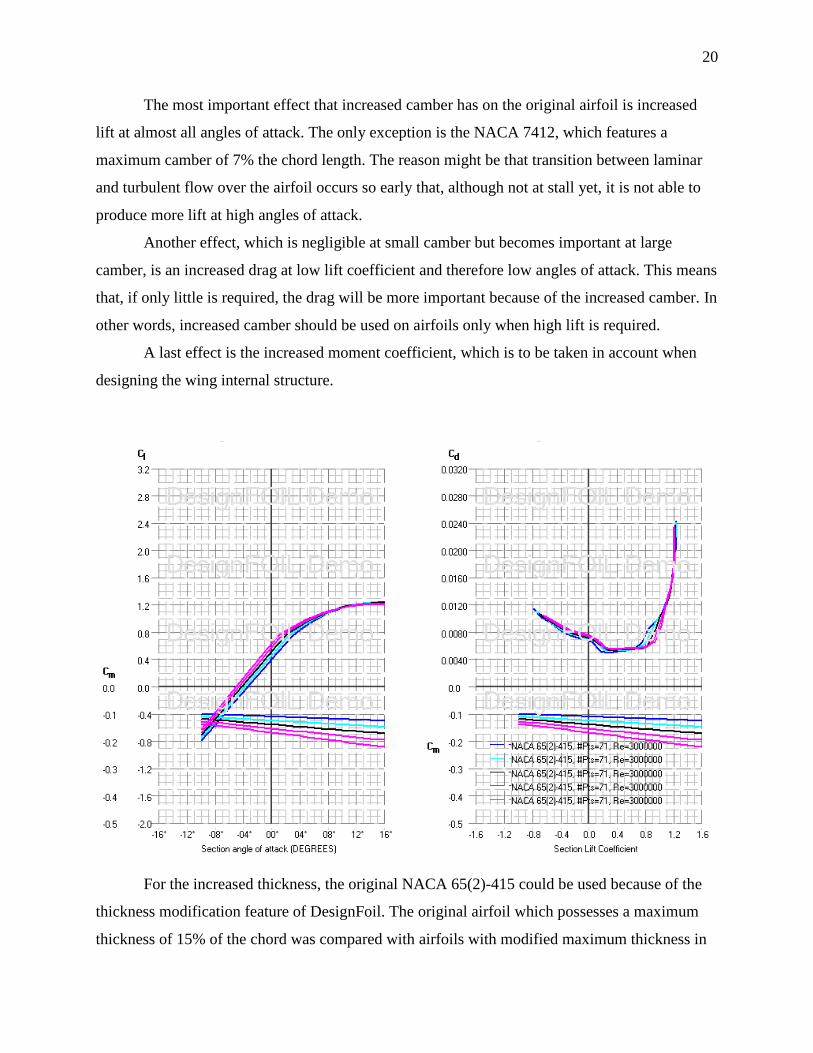
The most important effect that increased camber has on the original airfoil is increased
lift at almost all angles of attack. The only exception is the NACA 7412, which features a
maximum camber of 7% the chord length. The reason might be that transition between laminar
and turbulent flow over the airfoil occurs so early that, although not at stall yet, it is not able to
produce more lift at high angles of attack.
Another effect, which is negligible at small camber but becomes important at large
camber, is an increased drag at low lift coefficient and therefore low angles of attack. This means
that, if only little is required, the drag will be more important because of the increased camber. In
other words, increased camber should be used on airfoils only when high lift is required.
A last effect is the increased moment coefficient, which is to be taken in account when
designing the wing internal structure.
For the increased thickness, the original NACA 65(2)-415 could be used because of the
thickness modification feature of DesignFoil. The original airfoil which possesses a maximum
thickness of 15% of the chord was compared with airfoils with modified maximum thickness in
21
increments of 2%, i.e. the first airfoil of the chart has 15% of the chord maximum thickness, the
second has 17%, the third has 19%, and so on.
The most important consequence of increasing maximum thickness is an important
increase in moment coefficient. This can lead to important changes in the wing internal
structures. Also, at low angles of attack, which represent mainly the region that is not close to
stall angle, lift coefficient is slightly increased by the increased thickness. Drag does not get
modified except that it gets shifted toward higher lift coefficients.
22
References Avallone, Eugene A., Theodore Baumeister III, Ali Sadegh. Marks’ Standard Handbook for
Mechanical Engineers, Eleventh Edition. NY: McGraw-Hill Professional Publishing, 2006. Book.
Camtrell, Paul. Angle of Attack-Helicopter Aviation. Web. 10 December 2013. Jackson, Doug. Wing Twist and Dihedral. 2 December 2001. Web. 10 December 2013.